THEORY AND APPLICATION OF RF/MICROWAVE ABSORBERS Microwave Absorbers-Laird...ABS-CS-RF Microwave...
24
ABS-CS-RF Microwave Absorbers_081214 1 TECH NOTES THEORY AND APPLICATION OF RF/MICROWAVE ABSORBERS Absorbers in the RF/microwave realm are materials that attenuate the energy in an electromagnetic wave. Absorbers are used in a wide range of applications to eliminate stray or unwanted radiation that could interfere with a system’s operation. Absorbers can be used externally to reduce the reflection from or transmission to particular objects and can also be used internally to reduce oscillations caused by cavity resonance. They can also be used to recreate a free space environment by eliminating reflections in an anechoic chamber. Absorbers can take many different physical forms including flexible elastomers or foam or rigid epoxy or plastics. They can be made to withstand weather and temperature extremes. Absorbers have become a critical element in some systems to reduce interference between circuit components. This paper will attempt to cover all aspects of absorbers from basic theory through absorber applications and types plus testing methods. RF/Microwave absorbers come in a vast range of different types TECH NOTES THEORY AND APPLICATION OF RF/MICROWAVE ABSORBERS
Transcript of THEORY AND APPLICATION OF RF/MICROWAVE ABSORBERS Microwave Absorbers-Laird...ABS-CS-RF Microwave...

ABS-CS-RF Microwave Absorbers_081214 1
TECH NOTES THEORY AND APPLICATION OF RF/MICROWAVE ABSORBERS
Absorbers in the RF/microwave realm
are materials that attenuate the
energy in an electromagnetic wave.
Absorbers are used in a wide range
of applications to eliminate stray or
unwanted radiation that could
interfere with a system’s operation.
Absorbers can be used externally to
reduce the reflection from or
transmission to particular objects and
can also be used internally to reduce
oscillations caused by cavity resonance.
They can also be used to recreate a free space
environment by eliminating reflections in an anechoic chamber.
Absorbers can take many different physical forms including flexible elastomers or
foam or rigid epoxy or plastics. They can be made to withstand weather and
temperature extremes. Absorbers have become a critical element in some
systems to reduce interference between circuit components. This paper will
attempt to cover all aspects of absorbers from basic theory through absorber
applications and types plus testing methods.
RF/Microwave absorbers come
in a vast range of different types
TECH NOTES THEORY AND APPLICATION OF RF/MICROWAVE ABSORBERS

ABS-CS-RF Microwave Absorbers_081214 2
TECH NOTES THEORY AND APPLICATION OF RF/MICROWAVE ABSORBERS
TABLE OF CONTENTS
TABLE OF CONTENTS ..........................................................................................................................2
ABSORBER THEORY ............................................................................................................................3
ABSORBER TYPES ...............................................................................................................................5
ABSORBER APPLICATIONS ..................................................................................................................8
PARAMETER TEST METHODS ............................................................................................................ 12
ABSORBER TEST METHODS ............................................................................................................... 14
ABSORBER THEORY .......................................................................................................................... 17
Reflection and Transmission at a Material Boundary ............................................................................... 16
Wave Propagation in Absorbers............................................................................................................... 19
GLOSSARY ....................................................................................................................................... 21
ACKNOWLEDGEMENTS .................................................................................................................... 24

ABS-CS-RF Microwave Absorbers_081214 3
TECH NOTES THEORY AND APPLICATION OF RF/MICROWAVE ABSORBERS
ABSORBER THEORY
Absorbers generally consist of a filler material inside a material matrix. The filler consists of one or
more constituents that do most of the absorbing. The matrix material is chosen for its physical
properties (temperature resistance, weatherability, etc.).
Absorbers are characterized by their electric permittivity and magnetic permeability. The permittivity is
a measure of the material’s effect on the electric field in the electromagnetic wave and the
permeability is a measure of the material’s effect on the magnetic component of the wave. The
permittivity is complex and is generally written as
ε* = ε '− jε"
The permittivity arises from the dielectric polarization of the material.
The quantity ε’ is sometimes called the dielectric constant which is
something of a misnomer when applied to absorbers as ε’ can vary
significantly with frequency. The quantity ε” is a measure of the
attenuation of the electric field caused by the material. The electric loss
tangent of a material is defined as
The greater the loss tangent of the material, the greater the attenuation as the wave travels
through the material. Analogous to the electric permittivity is the magnetic permeability which is
written as
µ* = µ'− jµ"
With magnetic loss tangent defined as
The permeability is a measure of the material’s effect on the magnetic field. Both components
contribute to wavelength compression inside the material. Additionally, due to the coupled EM
wave, loss in either the magnetic or electric field will attenuate the energy in the wave.
In most absorbers, both permittivity and permeability are functions of frequency and can vary
significantly over even a small frequency range. If the complex permittivity and permeability are
known over a frequency range then the material’s effect on the wave is completely known.
Knowledge of the
permittivity and
permeability of materials
is essential to modeling
absorber performance.
If those values are
known then material
performance is
completely determined.

ABS-CS-RF Microwave Absorbers_081214 4
TECH NOTES THEORY AND APPLICATION OF RF/MICROWAVE ABSORBERS
The units of permittivity are farads/meter and the permeability units are henrys/meter. The actual
values for most materials can be cumbersome in calculation. For this reason they are usually
compared to the permittivity and permeability of a vacuum. These values are
ε0 = 8.854x10
−12 farads / mete and µ
0 = 4πx10
−7 henrys / meter
The values ε* and µ* then become dimensionless. Since ε is dependent on the dielectric
polarization which always opposes the electric field, ε for all materials is greater than that of free space
and hence is always greater than 1.
Typical parameters for a magnetic
microwave absorbent material
Anisotropic Parameters
Most absorber filler materials are spherical in shape leading
to isotropic electromagnetic parameters i.e. propagation
and attenuation in the material is independent of
direction. For nonspherical fillers the parameters may by
anisotropic in which case the single values permittivity and
permeability must be replaced by a 3x3 tensor
Generally the coordinate system can be rotated to make all
but the diagonal components equal to zero.

ABS-CS-RF Microwave Absorbers_081214 5
TECH NOTES THEORY AND APPLICATION OF RF/MICROWAVE ABSORBERS
ABSORBER TYPES
Free Space
Free space absorbers come in two broad types, reflectivity absorbers and insertion loss absorbers.
Reflectivity absorbers reduce the reflection level compared to a perfect reflector (metal plate). Insertion
loss absorbers reduce the signal travelling from point A to point B
Reflectivity-Narrowband
Any single layer homogeneous material will resonate when its
thickness is equal to ¼ wavelength. A useful visualization is that
the incoming wave will be partially reflected by the front surface
of the material while part is transmitted. This transmitted wave
then propagates through to the back of the absorber where it
undergoes total reflection and propagates back through the front
face of the absorber. If the wave reflected off the front face is
equal in magnitude and 180o out of phase with the wave
reflected off the back face then the waves will cancel and there
will be no total reflection. This phenomenon will occur when the
transit distance for the wave through the material is 180o. Since the wave transits the material twice, it
will occur when the material has a thick- ness of ¼ wavelength. While this is a useful visualization it is
not entirely accurate.
There are no separate reflections off the front and back surface. Like virtually everything else in the
microwave engineering world, absorber design is an impedance matching problem, in this case matching
the impedance of a metal surface (Z=0) to the impedance of free space (Z=377 ohms). If the impedance
seen by the wave at the surface of the material is equal to 377 ohms, the wave will be completely
absorbed by the material.
One of the earliest absorber types which is inherently narrowband is known as the Salisbury screen. The
impedance at a metal surface is equal to zero. At one quarter wavelength in front of the surface the
impedance will be infinite and the admittance will be zero. If a resistive sheet with surface resistivity
equal to 377 ohms is placed here, the impedance will be equal to 377 ohms.
Since this only works when the substrate material is ¼ wavelength a Salisbury screen is inherently
narrowband.
Reflectivity-Broadband
Multilayer
Several absorber types exhibit broadband reflectivity
performance. Multiple discrete layers can be stacked which

ABS-CS-RF Microwave Absorbers_081214 6
TECH NOTES THEORY AND APPLICATION OF RF/MICROWAVE ABSORBERS
will enable the 377 ohm input impedance condition over a broader range of frequencies. The design of
this class of material is similar to de- sign for a quarter wave transformer.
Impedance gradient
A second class of broadband absorbers uses an impedance gradient. The
impedance at the front face is very close to 377 ohms but gradually reduces to
zero ohms at the back face. Since there is no abrupt transition layer, there is
no point which will cause a large reflection. This impedance gradient can take
either of two forms. The first is a physical gradient where the material is
homogeneous but is formed in a shape such that the wave ‘sees’ a small portion of the material at the
front face and a gradually increasing portion as it travels into the material. The most common shape for
this type of material is a pyramid. These are the highest performing absorbers with outstanding
reflectivity (better than –50dB) and are usually used in anechoic chambers.
The second type of impedance gradient absorber uses a parameter gradient. In these absorbers, the
material is a flat sheet but the electrical parameters within the sheet will vary continuously with depth
into the absorber. This class of absorbers is capable of better than –20 dB reflectivity performance over
wide bands.
Jaumann absorber
A Jaumann absorber extends the Salisbury screen concept to multiple layers. Resistive sheets separated
by low loss dielectrics enable broadband performance to be achieved. In general, the resistivity of the
sheets decreases from front to back in a Jaumann absorber. Since the low loss spacer material is usually
a closed cell foam, a Jaumann exhibits inherent water resistance and light weight.
Enclosed Space (Cavity Resonance)
The physics governing absorber performance in an enclosed space is
different than that governing performance in a free space
volume. In an enclosed space, there are no propagating waves,
only standing waves. In standing waves the E field and H field
are 90o out of phase with each other. Material thickness is not as
crucial as it is with free space absorbers since material resonance is
not the goal. In cavity resonance damping the absorber is a high permittivity/permeability material
that will attract the energy and absorb it. Since the tangential magnetic field is at a maximum
(MISSING COPY HERE?)
Absorber Forms
Magnetic-Magnetic absorbers utilize a filler with ferromagnetic
properties. This gives the absorber a high permeability and high
Pyramidal absorber
A cavity resonance absorber molded in
place inside a circuit board
A magnetic elastomer absorber

ABS-CS-RF Microwave Absorbers_081214 7
TECH NOTES THEORY AND APPLICATION OF RF/MICROWAVE ABSORBERS
magnetic loss. Advantages include the ability to greatly compress the wavelength due to the high
permeability enabling quarter wavelength resonant absorbers at a thickness that are a fraction of the
free space wavelength. Also, magnetic absorbers are best for cavity resonance damping since the
magnetic field is a maximum on the conductive surface where the absorber is placed. Disadvantages of
magnetic
absorber include weight and cost.
Magnetic absorbers come in several elastomer forms including silicone, urethane, nitrile and neoprene.
The matrix material is generally chosen for its physical properties. Magnetic absorbers are also available
in a rigid epoxy form. These absorbers are easy to machine and are generally used in load applications.
Dielectric
Dielectric absorbers have no magnetic properties (i.e. µ=1). The loss mechanism is
purely dielectric. The loss can arise from a variety of sources within the dielectric.
Dielectric absorbers are usually made in a low cost foam form but can also be
used with elastomers. Advantages are low cost and weight. Disadvantages are
higher conductivity preventing usage in contact with electronic equipment and
their lack of performance in most cavity resonance applications due to their lack
of magnetic absorption.
Moldable
Both magnetic and dielectric absorbers are available in moldable forms. This
could be a two part liquid which cures at room or elevated temperatures or could
be in the form of injection moldable pellets.
A range of dielectric
foam absorbers

ABS-CS-RF Microwave Absorbers_081214 8
TECH NOTES THEORY AND APPLICATION OF RF/MICROWAVE ABSORBERS
ABSORBER APPLICATIONS
Cavity Resonance Reduction
Often after a circuit is designed and tested it must be properly shielded and physically protected before
it can be put into use. This usually involves covering the entire circuit with a metallic cover. While
providing adequate shielding and protection the cover can introduce problems of its own. It can create
conductive cavities that will resonate if stimulated at one of its resonant frequencies. This cavity
resonance introduces E and H fields across the cavity that can seriously impact the circuit performance.
The correct absorber material when introduced to the cavity can
damp the resonance, enabling proper operation of the circuit.
In a rectangular cavity the resonant frequencies are given by
Where m, n, and p are indices indicating the number of half
wavelengths across the x, y, and z dimensions of the cavity
respectively. The cavity will resonate at frequencies determined
by the cavity dimensions. The dominant resonant mode is similar
to the TE01 waveguide mode but chosen with the first zero of sin(βz).
This mode is designated the TE011 mode. The TE011 mode is the lowest
frequency at which the cavity can support a cavity resonance.
Below this frequency, a cavity resonance will not exist. For an empty cavity,
the cutoff frequency corresponds to where the longest dimension of the
cavity is equal to 1/2 free space wavelength.
The equations governing the field distribution of the TE011 mode are
as follows
Virtually every
component of a
microwave system
uses absorbers.
Proper choice of
absorber materials is
a cost effective way
to enhance design.

ABS-CS-RF Microwave Absorbers_081214 9
TECH NOTES THEORY AND APPLICATION OF RF/MICROWAVE ABSORBERS
Note the j in front of the equations for the H fields.
This indicates that the magnetic field is 90o out of phase
with the electric field. This means that when the
electric field is at its maximum, the magnetic field is
zero and vice versa. Since the impedance at a given
point is proportional to the E field divided by the H
field, the cavity resonance can cause wild swings in
impedance across a cavity.
The illustrations at left show the electric and
magnetic field norms for two different cavity modes.
Note that where the electric field is strong, the
magnetic field is weak.
When an absorber is inserted into the cavity, the high
permittivity/permeability of the absorber causes the
energy to move into the absorber. The field equations
are too complex to solve directly for a partially filled
cavity but using Finite Element Method (FEM) software
solutions for the fields can be found. Note in the third
illustration how virtually all of the magnetic energy
resides in the absorber. The higher the permittivity
and permeability the more the energy ‘wants’ to go
into the material. Recall from basic electromagnetic
theory that the tangential electric field is zero on a
conducting wall while the magnetic field is maximum.
For this reason, magnetically loaded absorbers are the
most effective in damping cavity resonances.
A range Field distribution of TE011 mode inside an
empty cavity
Field distribution of TE032 mode inside an empty
cavity dielectric foam absorbers
Field distribution in cavity with magnetic absorber at
1mm thickness fr=2.36 GHz

ABS-CS-RF Microwave Absorbers_081214 10
TECH NOTES THEORY AND APPLICATION OF RF/MICROWAVE ABSORBERS
Near Field Absorbers
Near field absorbers are a class of absorbers that are placed near or directly upon a radiating element.
Since the energy in the near field is predominantly magnetic, near field absorbers have high magnetic
permeability and high magnetic loss. Also, since they are often in direct contact with circuit elements,
they must have very low conductivity.
Even the best designed circuit will contain elements that will resonate and radiate at particular
frequencies. These radiators could be inductors or capacitors or connecting wires that will behave
differently at certain frequencies. In the near field most of the radiated energy is magnetic so radiators
are modeled as a loop antenna. Magnetic energy dies off very quickly with distance but can still
interfere with nearby circuit components.
Near field modeling consists of exciting a loop antenna and determining the coupling to the test antenna
(also a loop). Coupling is compared after placing an absorber material nearly in contact with the loop.
Absorber molded in place in a circuit board cover to
damp cavity resonances
Near field model with coupling loop
antennas with and without absorber
FEM model of coupling loop antennas illustrating electromagnetic
power loss in absorber material

ABS-CS-RF Microwave Absorbers_081214 11
TECH NOTES THEORY AND APPLICATION OF RF/MICROWAVE ABSORBERS
Loads
Microwave terminations are waveguide or coax sections that present low reflections to the incoming
wave. Terminations are used in many microwave systems such as
circulators or couplers to eliminate unwanted signals. A
termination must be able to absorb the incident energy, hence
the use of absorber load material.
A load must absorb over the entire waveguide band and is
therefore shaped to present an impedance taper to the
incoming wave. Load materials are generally magnetic
absorbers which are easily machined or molded.
Millimeter Wave Absorbers
Different modes of analysis and absorber types are
needed in the RF/microwave band depending upon
whether the absorber is used in free space or inside an
enclosed cavity. Absorbers for free space reflectivity or
insertion loss use a different design philosophy than for
cavity resonance reduction. Most applications in the
RF/microwave realm are clearly one or the other. The
physics will change somewhat as we move into
millimeter waves. Even a physically small cavity or
enclosure could encompass several wavelengths at
millimeter wave frequencies. Where is the line dividing
a free space application from a cavity application?
Load absorbers
The image on the left is the electric field distribution inside a
cavity approximately 2 wavelengths in dimension. Note the
clearly delineated resonance peaks indicating cavity
resonance. The image on the right is the electric field
distribution inside a cavity >10 wavelengths. While there
appears to be some resonant behavior there are clearly some
propagating elements as well.

ABS-CS-RF Microwave Absorbers_081214 12
TECH NOTES THEORY AND APPLICATION OF RF/MICROWAVE ABSORBERS
Since there is no hard boundary separating free space from cavity resonance, electromagnetic modeling
must be used. Modeling of the field distribution inside cavities of different dimensions compared to a
wavelength indicate a breakdown of cavity resonance behavior at a cavity size around 5 wavelengths.
At millimeter wave frequencies this could be smaller than 1”. This quasi- free space region requires
different absorber solutions, requiring different absorber types than those used at lower frequencies.
Reflection Reduction
Any system that transmits energy can experience interference from reflections back to the transmitter.
Also, unwanted reflections can interfere with other systems. Often the reflection source cannot be
moved as with a building or a ship’s mast. Absorbers can then be used to reduce the reflection level.
Typical reflectivity reduction for weather resistant outdoor absorber material is –20dB which will
eliminate 99% of the reflection. Care must be taken that the chosen absorber is designed to absorb
at the transmit frequency.
Radar Cross Section Reduction (RCSR)
Absorbers can also be used to reduce the radar cross section of a target object. By reducing the
reflection level the object will present a smaller cross section. However, due to the narrowbanded
performance of thin radar absorbent material (RAM) and the thickness and weight of broadband RAM,
it is difficult to achieve effective radar cross section reduction using absorber alone.
Anechoic Chambers
Anechoic chambers are used to create a free space condition in an enclosed room. Very high performance
absorber material is used on the walls, ceiling and floor to eliminate reflections. Reflectivity of absorbers
used in anechoic chambers can be –50dB or better. That level of performance is critical to guaranteeing a
successful antenna or radar cross section test in a weatherproof secure environment.
PARAMETER TEST METHODS
Accurate measurement of electromagnetic parameters is critical to
modeling the performance of microwave absorbers. The electric
permittivity ε*=ε’-jε” and magnetic permeability µ*=µ’-jµ” are, in general
functions of the frequency so swept frequency
methods are desired.
At low frequencies (<1 GHz) parameters can be
measured using an impedance analyzer with
custom test fixtures. The permittivity test fixture
measures the capacitance of two parallel test
heads both with and without the material under
test. The permittivity is then derived from the

ABS-CS-RF Microwave Absorbers_081214 13
TECH NOTES THEORY AND APPLICATION OF RF/MICROWAVE ABSORBERS
capacitance. The permeability is determined from the change in inductance of a cylindrical cavity by
insertion of a donut shaped MUT. Very good results can be found down to 1 MHz.
At higher frequencies measuring the capacitance or inductance no longer yields satisfactory results and
field theory must be used. Parameter measurement testing at these frequencies entail sending a wave
into the material and measuring the material response. Since 4 results are needed (real and imaginary ε,
µ), 4 measurements need to be taken on a sample which are usually the magnitude and phase of S11
(reflection) and S21 (transmission) through the sample. If it is known that the material has no magnetic
components (µ=1) then the electric permittivity can be determined with 2 measurements, S11
magnitude and phase or S21 magnitude and phase.
While free space measurements of reflection/transmission
amplitude and phase have yielded good results the best results are
seen in closed systems using coaxial lines or waveguides. In these
cases the calibration of the
network
analyzer is
critical. Full 2 port calibration or TRL
calibration is needed for accurate phase measurements, particularly of reflection.
Sample fit inside the coax or waveguide is very important as a poorly fit sample
will not yield good results. As frequencies extend into millimeter waves,
calibration and sample fit become even more critical due to the short wavelength.
For non-magnetic material, free space techniques can yield excellent results all the way up through
millimeter waves. It is much more straightforward to measure transmission phase plus good
measurements can be made in free space eliminating the sample fit problem.
Insertion loss/phase test fixture for
broadband parameter measurement
of non-magnetic material
Waveguide and coaxial test fixtures

ABS-CS-RF Microwave Absorbers_081214 14
TECH NOTES THEORY AND APPLICATION OF RF/MICROWAVE ABSORBERS
ABSORBER TEST METHODS
Attenuation
Attenuation is a measure of how much a wave propagating through a material is attenuated. It is not a
direct measurement but is calculated from the material’s complex permittivity and permeability. The
definition is that if all space is filled with the material, a wave will attenuate at this rate per unit
distance. Attenuation is usually expressed in dB/cm. Attenuation values do not relate directly to any
particular measurement and the reader should be cautioned about using the numbers to predict
reflectivity. It is used to compare the relative absorption of different materials. In any real world
situation, the material impedance must also be taken into account. Attenuation in dB/cm is given by
Near Field Test
Near field interference takes several forms so there is no
single test that suffice to fully characterize the performance of
near field absorbers. The IEC has designated four tests to
measure noise suppression of near field absorbers.
• Intradecoupling ratio – This test is designed to
measure the effective- ness of the absorber in
reducing the coupling between elements on the same
side of the absorber sheet. Two loop antennas are
deployed as illustrated on the right. The coupling
between the antennas is measured and the absorber is
placed above the loops and the coupling compared to
the case with not absorber
• Interdecoupling ratio – This test measures the absorber effectiveness when the source and
receiver are on opposite sides of the absorber. The setup is the same as for intradecoupling ratio
but in this case the absorber sheet is placed between the antenna loops
• Transmission Attenuation Power Ratio – This test measures the effectiveness of the absorber in
suppressing current noise along a printed circuit board. A microstrip line is used and
transmission and reflection characteristics measured. The material is then place on top of the
conductor and transmission and reflection remeasured.
• Radiation suppression ratio – This rest requires an anechoic chamber. The microstrip line is used
as the source and the radiated emissions at a fixed distance away is measured.
Microstrip Line test fixture
Coupled loops for inter and intra decoupling test

ABS-CS-RF Microwave Absorbers_081214 15
TECH NOTES THEORY AND APPLICATION OF RF/MICROWAVE ABSORBERS
NRL Arch
The NRL Arch is the industry standard for testing the reflectivity of materials. Originally designed at the
Naval Research Laboratory, the NRL Arch allows for quick, repeatable non-destructive testing of
microwave absorbent materials over a wide frequency range.
Reflectivity is defined as the reduction in reflected power caused by the introduction of an absorbent
material. This reduction in power is compared to a ‘perfect’ reflection which is approximated very well
by the reflection off a flat metallic plate.
As seen in the diagram below, an NRL arch consists of a transmit and receive antenna which are
oriented towards a metal plate. To measure normal incidence reflectivity the antennas are located as
close to each other as physically possible. Absorbent material is often used to minimize antenna cross
talk. The antennas can be located anywhere on the arch to allow measurements of performance at off
normal angles of incidence with the practical limitation of the ability to separate the signal from the
material under test from the direct antenna to antenna cross talk.
In general a network analyzer is used for measurements on an NRL Arch to provide both the stimulus
and the measurement. A calibration is performed by measuring the resultant power reflecting off the
metal plate over a broad frequency range. This is established as the ‘perfect’ reflection or 0 dB level. The
material under test is then placed on the plate and the reflected signal measured in dB. Time domain
gating may be used to eliminate antenna cross talk and reduce the error introduced by room reflections.
The size of the material under test and the antenna to plate distance are determined by the desired
frequency range of test. A standard setup tests from 2-18 GHz using a material size of 12”x12” or
24”x24” and an antenna to plate distance of 30”-36”. Lower frequency (longer wavelength) testing
would require a larger sample size and longer antenna-plate distance. Higher frequencies could use a
smaller arch and sample size.
An NRL Arch for millimeter wave measurements
ABS-CS-RF Microwave Absorbers_081214 16
TECH NOTES THEORY AND APPLICATION OF RF/MICROWAVE ABSORBERS
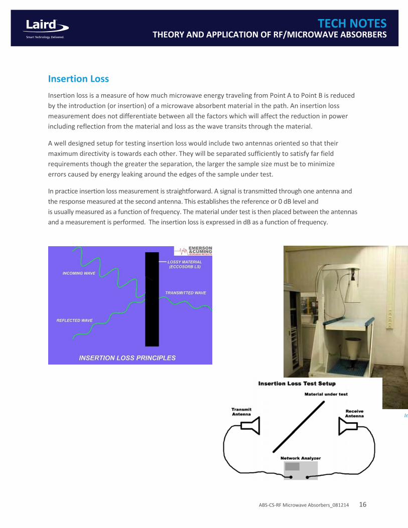
Insertion Loss
Insertion loss is a measure of how much microwave energy traveling from Point A to Point B is reduced
by the introduction (or insertion) of a microwave absorbent material in the path. An insertion loss
measurement does not differentiate between all the factors which will affect the reduction in power
including reflection from the material and loss as the wave transits through the material.
A well designed setup for testing insertion loss would include two antennas oriented so that their
maximum directivity is towards each other. They will be separated sufficiently to satisfy far field
requirements though the greater the separation, the larger the sample size must be to minimize
errors caused by energy leaking around the edges of the sample under test.
In practice insertion loss measurement is straightforward. A signal is transmitted through one antenna and
the response measured at the second antenna. This establishes the reference or 0 dB level and
is usually measured as a function of frequency. The material under test is then placed between the antennas
and a measurement is performed. The insertion loss is expressed in dB as a function of frequency.
Insertion Loss test fixture

ABS-CS-RF Microwave Absorbers_081214 17
TECH NOTES THEORY AND APPLICATION OF RF/MICROWAVE ABSORBERS
ABSORBER THEORY
Reflection and transmission of waves at a material boundary
Absorbers are used to eliminate unwanted electromagnetic energy. In free space they do so by
presenting an impedance to an incoming wave equal to the impedance of free space (377 Ω). At a
material interface, the incident, reflected and refracted waves must obey the boundary condition that
the sum of E and H fields of the waves must be continuous. Requiring continuity of the amplitudes leads
to Fresnel’s equations. Continuity of phase leads to Snell’s Law. Reflection from a dielectric interface
depends on the polarization. There are two polarization states defined. Parallel polarization occurs
when the electric field vector is parallel to the plane of incidence. The plane of incidence is defined by
the vector normal to the material and the propagation direction of the incident wave. Perpendicular
polarization occurs when the electric field vector is perpendicular to the plane of incidence.
The phase delay experienced by the wave in propagating a distance d is given by
Where λ is the free space wavelength. Note that for a non-magnetic material these equations are
simplified by µ*=1
The interface reflection coefficients are only half the story though. Eventually the wave will reach the other
side of the absorber and reflect. The total reflection is then derived from the sum of the reflected waves.
The voltage reflection coefficient for a thickness d of a material is
where r is the appropriate interface reflection coefficient.
Reflection coefficients are usually expressed in dB
The voltage transmission coefficient is given by
Transmission coefficient in dB is given by

ABS-CS-RF Microwave Absorbers_081214 18
TECH NOTES THEORY AND APPLICATION OF RF/MICROWAVE ABSORBERS
In most cases with absorbers the material is backed by metal. The total reflection coefficient (now called
the reflectivity) becomes
And the reflectivity in dB is given by
An alternative method of prediction is to treat the problem as a transmission line containing an
absorber with a thickness d . The input impedance at the front of the absorber is then
Where
ZL = the load impedance seen at the back of the absorber
ZC = characteristic impedance of absorber material =
α and β are the attenuation and propagation coefficients respectively and are derived from
Where
For a single layer metal backed absorber the equation is simplified because ZL=0 giving
The reflection coefficient is then found by comparing to the impedance of free space (377 Ω)
And

ABS-CS-RF Microwave Absorbers_081214 19
TECH NOTES THEORY AND APPLICATION OF RF/MICROWAVE ABSORBERS
The input impedance method is easier computationally than the reflection-transmission method but it
cannot predict performance at off normal angles. The input impedance method can model multiple
layer absorbers by replacing the load impedance ZL by the input impedance of the preceding layer. The
reflection-transmission method cannot. A third method must be used to predict off-normal performance
of multiple layer absorbers.
The problem of modeling multiple layer absorbers at off normal incidence angles is solved by using the
wave amplitude transmission matrix method. The voltages on either side of a junction are related by
Where S11 and S22 are the reflection coefficients of each layer looking towards side 1 and side 2 of the
absorber respectively and S12 and S21 are the transmission coefficients of each layer from side 2 towards
side 1 and side 1 towards side 2 respectively. For a homogeneous layer the equation is simplified since
S11=S22 and S12=S21. This simplifies the matrix to
Where R and T are calculated using the reflection-transmission equations. To model multiple layers the
matrices for each layer are multiplied. The result is a 2x2 matrix from which the multilayer reflection
and transmission coefficients can be derived.
The metal backed reflection coefficient is given by

ABS-CS-RF Microwave Absorbers_081214 20
TECH NOTES THEORY AND APPLICATION OF RF/MICROWAVE ABSORBERS
Wave Propagation in Absorbers
For waves in a material two of Maxwell’s equations can be written as
Differentiating each equation by t and substituting yields
If it is assumed that E and H are functions of x and t only the solution is a plane wave
and
Expanding gives
A nonzero α leads directly to an exponential attenuation of the wave. The complex exponential leads to
a time period of
and a space period (wavelength)
For all materials with β>1 the wavelength will be compressed inside the dielectric compared to free
space by a factor of β. For a low loss material, a very good approximation to β is

ABS-CS-RF Microwave Absorbers_081214 21
TECH NOTES THEORY AND APPLICATION OF RF/MICROWAVE ABSORBERS
GLOSSARY
Anechoic – An environment with no reflections. Generally used with anechoic chamber as in a room
with no reflections off the walls
Angle of incidence – The angle measured from a perpendicular axis to the plane of a surface which
energy arrives at. "Normal incidence" refers to the perpendicular direction of propagation to the
surface. "Grazing Incidence" refers to energy arriving from the direction almost parallel to the surface
(high incident angle"). Important in the performance of specular absorbers.
Antenna – A device which increases the efficiency of transmission or reception of radio or radar signals
into or from a medium. For instance, transmitting and receiving antennas are the same device.
Attenuation – Loss of energy (i.e. conversion to heat) as radiation passes through a lossy (absorptive)
medium (expressed in dB). Function of the properties of the medium. In contrast to insertion loss or
reflectivity.
Capacitance – The ability of a capacitor to store electric energy
Cavity Resonance – An enclosed space will resonate at certain frequencies which could interfere with
the performance of a circuit inside. Resonant frequency depends on the dimensions of the cavity and
can be reduced by using absorbers
Coaxial line – A pipe (so called outer conductor) with a concentric wire (inner conductor) that is used
to carry microwave energy with little loss of power
Decibel (dB) – A logarithmic ratio (base 10) between two quantities denoted as ""dB."" In terms of
energy reflection: dB = 10 x LOG (power reflected/power reflected by metal plate) e.g. dB = 10 x
LOG(1/2) = -3 (50% reflected power)
Dielectric – A medium through which electric attraction or repulsion may be sustained - an insulator.
Dielectric Constant – The power loss in a dielectric due to heating as a wave passes through it. It can
be expressed as "dielectric loss tangent" (power factor) or "loss factor". Low loss makes a good
dielectric (ECCOSTOCK dielectric materials). High loss is an absorber (ECCOSORB), poor dielectric.
Electromagnetic field – A vector field of Electromagnetic energy. The Magnetic (H) and Electric (E) fields
generated by any system of electric charges. A low current, high voltage, source will generate mainly
an ELECTRIC FIELD. A high current, low voltage, source will generate mainly a MAGNETIC FIELD
Far Field – The region where Antenna patterns and RCS patterns need to be measured with adequate
transmission distance (in terms of wavelength) or they will not be typical of the patterns expected in
typical use over long distances. Measurements made over short distances (near field) contain errors
because the fields are curved rather than planar.
FEM – Finite Element Method-a type of electromagnetic modeling software
Free space – Refers to the medium of air (or vacuum) in which radio waves may travel. This is in
contrast to waves traveling on transmission lines such as coax or waveguide, or through a medium,
such as an Free Space Absorber (Specular Absorber)
Frequency – The number of cycles per second of an electromagnetic wave. Units: Hertz (Hz) 1-cycle.
KiloHertz (1000 cycles), Meg- aHertz (106 cycles), GigaHertz (109 cycles)
H field – the magnetic field

ABS-CS-RF Microwave Absorbers_081214 22
TECH NOTES THEORY AND APPLICATION OF RF/MICROWAVE ABSORBERS
Impedance – The ratio of electric to magnetic field (E/H)
Inductance – The ability of an inductor to store magnetic energy
Insertion Loss – The reduction in energy emitted from point A to reach point B caused by the
introduction (insertion) of an absorber material between the 2 points
Interface reflection coefficient – Reflection coefficient calculated from a single material interface
Isotropic/anisotropic – Isotropic materials have uniform electromagnetic properties independent of the
electric and magnetic field direction. Anisotropic materials have electromagnetic properties dependent
on the field direction
j=the square root of –1. Often used in exponential to exploit the fact that
Layer reflection coefficient – Reflection coefficient of a single layer of material
Loads/Terminations – Lossy slug of material which is used to terminate energy propagation in a
waveguide or coxial line with mini- mum impedance discontinuity
Loss tangent – The loss tangent is a parameter of a dielectric material that quantifies its inherent
dissipation of electromagnetic energy. The term refers to the angle in a complex plane between the
resistive (lossy) component of an electromagnetic field and its reactive (lossless) component
Lossy – The ability of a material to attenuate or absorb energy. Based on either the dielectric or
magnetic properties of the material.
Maxwell’s equations – A set of partial differential equations first published by James Clerk Maxwell in
1862 which form the foundation of classical electromagnetics
Microwave – Common usage of electromagnetic waves that refers to the frequency range of 700 MHz
to 40 GHz in the electromagnetic spectrum.
Millimeter wave – A portion of the electromagnetic spectrum with varying definitions but generally
covering the frequency band from 18-100 GHz (wavelengths~3-17 mm)
Near field – The near field is defined as the region very close to a radiating element (commonly < 1
wavelength) where the relation- ship between the electric and magnetic fields are complex with strong
inductive and capacitive effects from the antenna elements
Network analyzer – Device used for measuring the reflection and transmission frequency response of
microwave networks
NRL Arch – Is the standard system for measurement of reflection properties of absorber at high
frequencies. It involves bouncing microwaves from a metal plate and determining reflection properties
by alternately covering and uncovering the metal plate with the absorber piece under test. The
difference in signal level between these two conditions indicates the absorption capability of that
absorber.
Parameters – The permittivity and permeability of a material as a function of frequency
Permeability – measure of material’s effect on the magnetic field. Related to inductance. Generally written as
Permittivity – measure of material’s effect on the electric field. Related to capacitance. Generally written as

ABS-CS-RF Microwave Absorbers_081214 23
TECH NOTES THEORY AND APPLICATION OF RF/MICROWAVE ABSORBERS
Plane Wave – Propagating electromagnetic waves that are equal in magnetic and electric energy. In the
far field, all waves propagate as plane waves
Polarization – The orientation of the electric field of the radiation. Radiation transmitted from a dipole
antenna has its electric field parallel to the antenna. The wave travels in a direction perpendicular to the
antenna. The electric field of the radiation being transferred is perpendicular to the widest dimension of
the rectangle.
Radar Cross Section – Refers to the level of signal reflected from the radar target. The term RCS pattern
refers to the manner in which a specific target at a specific frequency varies in reflective signal level as
the target is rotated.
Reflection Coefficient – The ratio of reflected to incident energy
Reflectivity – The portion of incident energy which is reflected from a surface. A flat metal surface
reflects all incident radiation. Measured in dB which is a logarithmic measure of the portion of energy
reflected as compared to that reflected from a flat metal plate of the same area. A metal plate has a
reflectivity of 0 dB down. A material which reflects half of the incident energy is 3 dB down or has a
reflectivity of -3 dB. A material which reflects one tenth of the incident energy has a reflectivity of -10
dB. For flat sheet absorbers, 20 dB down is generally the best possible and desired performance
RF – Radio Frequency – frequency of radio waves, commonly 3 kHz-300 GHz
Salisbury Screen – Maybe the first ever anti-reflective concept RAM (radar absorbent material). The
most easy to understand salisbury screen design consists of a ground plane which is the metallic surface
that needs to be concealled, a lossless dielectric of a given thickness (a quarter of the wavelength that
will be absorbed) and a thin lossy screen
Sidelobes – side lobes are the lobes of the far field radiation pattern of an antenna that are not the main
beam
Standing Wave – If a wave continuously impinges on a surface (CW or continuous wave) a situation
often occurs where the voltage at any given point between the transmitter and receiver is constant. This
phenomenon is used to determine dielectric and magnetic properties of materials at radar frequencies.
Surface Currents – Traveling and creeping waves which contribute to RCS of an object. Also can
contribute to RFI in a micro- wave module.
VSWR – Voltage Standing Wave Ratio – The ratio of maximum to minimum of voltage over a single cycle
of field variation. Refers to the fact that, with reflections present, fields are periodic, i.e. they vary as a
sine wave in intensity. The greater the level of reflection, the greater the so called VSWR (the greater
the ratio of maximum to minimum over a single cycle of field variation).
Waveguide – Is a rectangular metal tube used to carry microwave energy with little loss of power. The
electric field of the radiation being transferred is perpendicular to the widest dimension of the
rectangle. A wave guide is useful over a narrow frequency range.

ABS-CS-RF Microwave Absorbers_081214 24
TECH NOTES THEORY AND APPLICATION OF RF/MICROWAVE ABSORBERS
ACKNOWLEDGEMENTS
Dielectric Materials and Applications
Arthur von Hippel, Editor
Paul Dixon Staff Scientist
Laird Technologies
28 York Avenue
Randolph, MA 02368
www.lairdtech.com
Any information furnished by Laird and its agents is believed to be accurate and reliable. All specifications are subject to change without notice. Responsibility for the use and application of Laird materials rests with the end user, since Laird and its agents cannot be aware of all potential uses. Laird makes no warranties as to the fitness, merchantability or suitability of any Laird materials or products for any specific or general uses. Laird, Laird Technologies, Inc or any of its affiliates or agents shall not be liable for incidental or consequential damages of any kind. All Laird products are sold pursuant to the Laird Technologies’ Terms and Conditions of sale in effect from time to time, a copy of which will be furnished upon request. © Copyright 2014 Laird Technologies, Inc. All Rights Reserved. Laird, Laird Technologies, the Laird Logo, and other marks are trademarks or registered trademarks of Laird Technologies, Inc. or an affiliate company thereof. Other product or service names may be the property of third parties. Nothing herein provides a license under any Laird or any third party intellectual property rights.