Theoretical Study Of Beam Transformations By Volume ...
136
University of Central Florida University of Central Florida STARS STARS Electronic Theses and Dissertations, 2004-2019 2011 Theoretical Study Of Beam Transformations By Volume Theoretical Study Of Beam Transformations By Volume Diffraction Diffraction Sergiy V. Mokhov University of Central Florida Part of the Electromagnetics and Photonics Commons, and the Optics Commons Find similar works at: https://stars.library.ucf.edu/etd University of Central Florida Libraries http://library.ucf.edu This Doctoral Dissertation (Open Access) is brought to you for free and open access by STARS. It has been accepted for inclusion in Electronic Theses and Dissertations, 2004-2019 by an authorized administrator of STARS. For more information, please contact [email protected]. STARS Citation STARS Citation Mokhov, Sergiy V., "Theoretical Study Of Beam Transformations By Volume Diffraction" (2011). Electronic Theses and Dissertations, 2004-2019. 1872. https://stars.library.ucf.edu/etd/1872
Transcript of Theoretical Study Of Beam Transformations By Volume ...

University of Central Florida University of Central Florida
STARS STARS
Electronic Theses and Dissertations 2004-2019
2011
Theoretical Study Of Beam Transformations By Volume Theoretical Study Of Beam Transformations By Volume
Diffraction Diffraction
Sergiy V Mokhov University of Central Florida
Part of the Electromagnetics and Photonics Commons and the Optics Commons
Find similar works at httpsstarslibraryucfeduetd
University of Central Florida Libraries httplibraryucfedu
This Doctoral Dissertation (Open Access) is brought to you for free and open access by STARS It has been accepted
for inclusion in Electronic Theses and Dissertations 2004-2019 by an authorized administrator of STARS For more
information please contact STARSucfedu
STARS Citation STARS Citation Mokhov Sergiy V Theoretical Study Of Beam Transformations By Volume Diffraction (2011) Electronic Theses and Dissertations 2004-2019 1872 httpsstarslibraryucfeduetd1872
THEORETICAL STUDY OF BEAM TRANSFORMATIONS
BY VOLUME DIFFRACTION
by
SERGIY V MOKHOV MS Taras Shevchenko National University of Kyiv 1996
MS University of Central Florida 2008
A dissertation submitted in partial fulfillment of the requirements for the degree of Doctor of Philosophy
in CREOL the College of Optics and Photonics at the University of Central Florida
Orlando Florida
Summer Term 2011
Major Professor Boris Ya Zeldovich
ii
copy 2011 Sergiy V Mokhov
iii
ABSTRACT
Laser beams can be manipulated by volume diffractive elements in addition to
conventional optical elements like mirrors lenses and beam splitters Conventional optical
elements can be described by applying the basic laws of reflection and refraction at the surfaces
of the elements Even diffraction by surface gratings utilizes relatively simple mathematics This
is to be contrasted with the volume diffraction which requires coupled wave theory in the slowly
varying envelope approximation (SVEA) to obtain accurate results Efficient spatially distributed
diffraction of laser beams is possible due to the high coherence of laser light and it occurs at
specific resonant Bragg conditions
This research work is inspired and driven by the successful development of recording
technology for robust high-efficiency volume Bragg gratings (VBGs) in photo-thermo-refractive
(PTR) glass Mostly VBGs of the reflective type are discussed in this dissertation Starting with
an analysis of electro-magnetic wave propagation in layered media we have reformulated
Fresnel and volume reflection phenomena in terms of a convenient parameter ndash strength of
reflection The influence that the different non-uniformities inside a VBG have on its spectral
properties has been examined One important result of this work is the proposal of moireacute VBG
and the derivation of an analytical expression for its bandwidth A multiplexed VBG used as a
coherent combiner is discussed as well Beam distortion via transmission through andor
reflection by a heated VBG due to residual absorption is analyzed
iv
To my mother Valentyna my father Valeriy and my sister Ludmyla
v
TABLE OF CONTENTS
LIST OF FIGURES vii
CHAPTER ONE INTRODUCTION 1
CHAPTER TWO STRENGTH OF REFLECTION 11
Parameterization of the transfer matrix by strength of reflection 11
Decomposition of Fresnel reflection in terms of strength of reflection 15
Propagation of electro-magnetic waves in layered media 16
Formalism of strength of reflection in other branches of physics 20
CHAPTER THREE PROPERTIES OF UNIFORM VBG AND FRESNEL CORRECTIONS 25
SVEA equations for reflection by VBG 25
Kogelnikrsquos analytical solution for a uniform VBG 27
Influence of Fresnel reflections 30
CHAPTER FOUR NON-UNIFORM VBGS 35
Propagation of EM waves in a non-uniform VBG 35
Theory of light reflection from a chirped VBG 37
CHAPTER FIVE RESONANT CAVITIES IN VBGS 40
Fabry-Perot resonator based on uniform VBGs 40
Resonant cavity in moireacute VBG 44
Bandwidth of resonant cavities in terms of strength of reflection 49
Bandwidth of a tunable moireacute filter 57
CHAPTER SIX MULTIPLEXED VBGS IN PTR GLASS 65
Properties of PTR glass 65
vi
Probabilistic amplitude masks for phase plates in PTR glass 67
Slanted reflective and transmissive VBGs 70
Multiplexed reflective VBG for coherent beam combining 78
CHAPTER SEVEN HIGH-POWER SPECTRAL BEAM COMBINING WITH VBGS UNDER
THERMAL DISTORTIONS 82
Beam quality parameter based on second moments 82
Hermite-Gaussian and Laguerre-Gaussian modes 86
Variation of losses with detuning in reflective VBG 89
Heat transfer in a VBG plate under laser beam exposure 94
Non-uniform heat transfer problem for a VBG plate with thermally stabilized edges 99
Deterioration of beam quality under operation by heated VBG 102
Spectral beam combining with thermally distorted VBGs 105
Higher tolerance of Super-Gaussian beams to thermal distortions 109
CHAPTER EIGHT CONCLUSION AND SUMMARY OF CONTRIBUTIONS 112
LIST OF REFERENCES 114
vii
LIST OF FIGURES
Figure 1 Notations for the incident A(z) and reflected B(z) waves in the approximation of infinitely wide plane
beams with account of the reflections from both boundaries z = 0 and z = L as well as the reflection
by the VBG 18
Figure 2 Solid lines potential well k02ndashk2(z) = ndash2cosh2z yielding non-reflection and incident beam energy
k02 = 009 Dashed lines fluxes |A(z)|2 and |B(z)|2 of counter-propagating wave function components 24
Figure 3 Reflectivity R of a VBG with account of the interference of reflection from the VBG alone with two
extra contributions from the two boundaries of the specimen for all possible phase combinations
Values of R are between the dashed curves for Fresnel 4 reflections from bare boundaries and are
between dotted curves for anti-reflection coatings (ARC) at 03 each 33
Figure 4 Asymmetry in transmission spectra Solid line our experiment dotted line our model 36
Figure 5 Reflection spectra of a uniformly chirped Bragg grating 38
Figure 6 Intensity profiles |A|2 and |B|2 inside a chirped VBG for the central resonant wavelength 39
Figure 7 Experimental setup for the coherent combination of two VBGs in PTR glass 41
Figure 8 Experimental transmission of two π-shifted VBGs 42
Figure 9 Spectral shift of resonant transmission due to phase shift Δγ between two grating modulations 43
Figure 10 Sketch of the envelope and simulated transmittance of a moireacute filter 46
Figure 11 Experimental spectral selectivity of a moireacute VBG filter 47
Figure 12 Transmission spectra of a tunable moireacute VBG filter at different illumination points 48
Figure 13 Photosensitivity curve of PTR glass depending on the exposure dosage 66
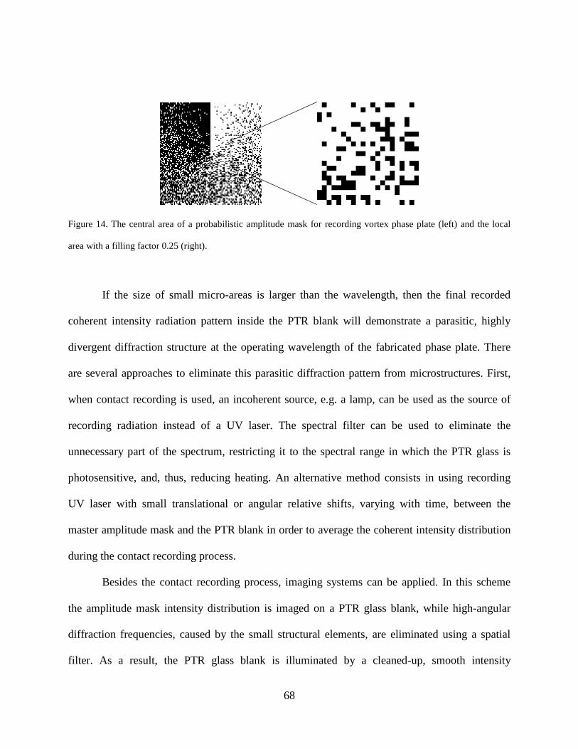
Figure 14 The central area of a probabilistic amplitude mask for recording vortex phase plate (left) and the
local area with a filling factor 025 (right) 68
Figure 15 4f optical system for spatial filtering 69
Figure 16 Beam geometries of slanted reflective and transmissive VBGs 72
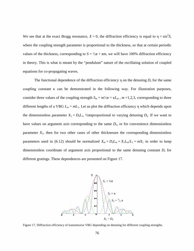
Figure 17 Diffraction efficiency of transmissive VBG depending on detuning for different coupling strengths 76
viii
Figure 18 Spectral properties of a double MVBG with three-wave coherent coupling a) notation of waves b)
incident wave F c) incident wave A 81
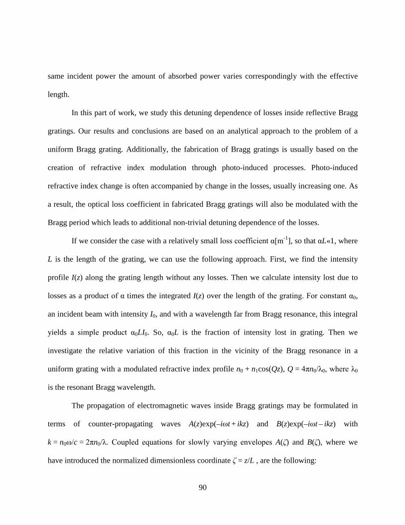
Figure 19 Experimental spectral reflection profile of a VBG compared with simulation (thin line) 92
Figure 20 Experimental variation of the absorption ratio versus the detuning and the analytical expression (thin
line) 93
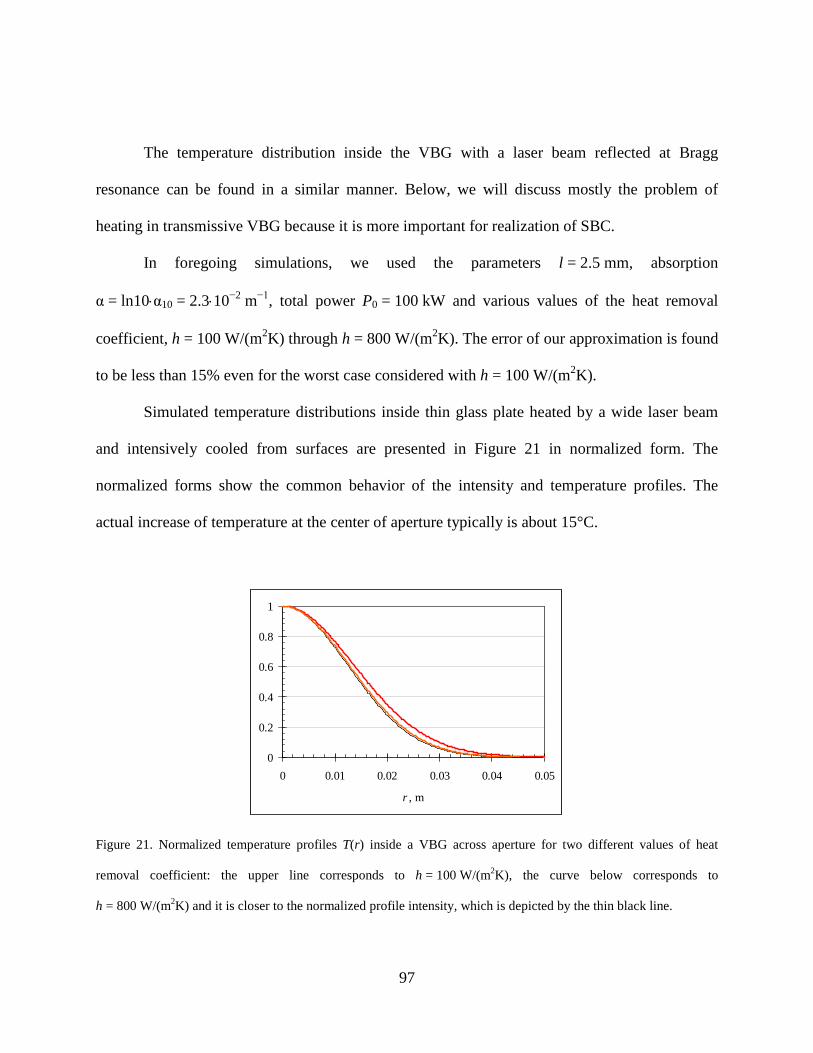
Figure 21 Normalized temperature profiles T(r) inside a VBG across aperture for two different values of heat
removal coefficient the upper line corresponds to h = 100 W(m2K) the curve below corresponds to
h = 800 W(m2K) and it is closer to the normalized profile intensity which is depicted by the thin
black line 97
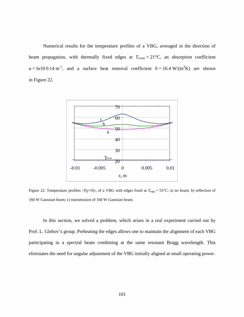
Figure 22 Temperature profiles lsaquoT(y=0)rsaquoz of a VBG with edges fixed at Tedge = 55degC a) no beam b) reflection
of 160 W Gaussian beam c) transmission of 160 W Gaussian beam 101
Figure 23 Scheme for spectral combining of N beams with the use of Nminus1 VBGs 106
Figure 24 Intensity profiles of Gaussian and super-Gaussian beams with the same power and widths
corresponding to the criterion of 001 of the residual power outside the circle with the same radius 110
Figure 25 Mx2 of Gaussian and super-Gaussian beams propagated through a heated glass plate as a function of
the absorbed power Csdotα10sdotPtot 110
1
CHAPTER ONE INTRODUCTION
Optics is one of the oldest parts of physics and its establishment was strongly connected
with the development of methods of transformation of light beams and the theoretical analysis of
these methods Starting from the basic reflection and refraction laws of geometrical optics
people came to create lenses first and then to create telescopes which has lead to the creation of
modern physics The methods of geometrical optics faithfully described the propagation of light
at that time and the usefulness of these methods only grew with time now they are fundamental
tools for any optical engineer around the world
Recognition of the wave nature of light has lead to the analysis of interference and
diffraction phenomena in optics Scalar wave theory is usually sufficient for the description of
such phenomena However in some cases like refraction of light at relatively large incidence
angles the methods of full-vectorial electromagnetic theory are required The spectral properties
of light waves usually become apparent through the material dispersion of optical elements or the
angular dispersion of surface diffractive gratings Modern branches of optics such as quantum
information require new quantum theoretical methods which will not be discussed in this
dissertation
During the last fifty years new light sources and lasers of different types were proposed
and built Light beams produced by lasers are characterized by high coherence and directionality
and thanks to these properties lasers find many applications in science and industry These
properties of laser beams allow one to manipulate them by a new method ndash volume diffraction
One of the most impressive realizations of volume diffraction is volume holography
2
This dissertation is devoted mostly to the general theoretical problems of the coherent
propagation and interaction of light with optical media and analytical and numerical calculations
of some particular applications with strong emphasis on the calculation of diffraction efficiencies
of different VBGs by coupled wave theory methods The recording material used for VBGs in
this dissertation is photo-thermo-refractive (PTR) glass It has advantages in comparison with
other materials those advantages being high uniformity low losses and high thermal stability
The topics covered in this dissertation are actually wider than just the calculation of the
reflection properties of particular holograms made in PTR glass The dissertation is based on up-
to-date published papers [1-5] and conference presentation abstracts [6-27] done by author in co-
authorship with his advisor Prof B Zeldovich and members of Prof L Glebovrsquos research group
Before starting an overview of the approaches and results in volume diffraction theory
we consider first a broader class of problems One of the most fundamental topics in
electrodynamics is the propagation of electromagnetic (EM) waves in layered media The term
ldquolayeredrdquo means that all properties of the media depend on one Cartesian coordinate only for
definiteness on z Almost any textbook on electrodynamics devotes considerable space to this
problem see eg [28-Born 99 29-Landau 84 30-Haus 84] The natural starting point in the
study of this subject is the consideration of reflection and refraction of an EM wave (of TE or
TM polarization) at a sharp plane boundary between two homogeneous media These phenomena
are quantitatively described by well-known Fresnel formulae The phenomena of propagation in
layered media are discussed in specialized books [31-Brekhovskikh 80 32-Yeh 88] The matrix
approach was used for example in [28-Born 99 30-Haus 84 32-Yeh 88] Detailed
consideration of boundary refraction and reflection of EM wave suffers from the absence of
3
generalization and often leads to recursive computational schemes for even simple layered
systems For example the reflectance of a plate is calculated in [31-Brekhovskikh 80 33-
Hecht 01] through the summation of a geometrical progression of powers of the reflection
coefficient with a phase factor accounting for the thickness of the plate
The importance of fundamental research in EM wave propagation has increased in recent
years due to active research in fabrication and analysis of metamaterials which have a negative
refractive index [34-Veselago 68 35-Pendry 03] There are no known natural materials with
such an unusual property However negative refraction was observed in a special artificially
created materials in the radio frequency range first [36-Shelby 01 37-Parazzoli 03 38-
Houck 03] and then in the optical spectrum [39-Shalaev 05 40-Sarychev 07 41-Dolling 07]
Another wide class of layered media with propagation parameters dependent upon one
coordinate consists of distributed feedback systems Kogelnik and Shank first proposed them for
integrated optics applications [42-Kogelnik 72] Distributed feedback structures couple counter-
propagating waves with opposite phase velocities in the body of the medium This is to be
contrasted with the feedback due to reflection at the boundaries Modulation of distributed
parameters leads to specific transmission and reflection properties of such systems As a result
they can be used as mirrors and filters and the most important of their characteristics is the
narrow spectral band width of their action [43-Schmidt 74] One fundamental realization of a
system with distributed parameters is a Bragg mirror which has a small sinusoidal modulation of
the material parameters usually this is a sinusoidal modulation of the real dielectric permittivity
When the propagation wavelength of incident wave in this media is equal to the round-trip
distance along one period of modulation the weak reflected waves from all periods interfere
4
constructively and strong reflection occurs at that wavelength If the input wavelength is tuned
away from this resonant Bragg condition the reflection rapidly drops The reflection coefficient
of more than 99 at the resonance frequency can be (and actually has been) achieved for a large
enough thickness of such a filter The functional dependence of this resonance reflection in the
reflection band is mostly flat The full spectral width of reflection of such a strong filter may be
kept to less than 200 picometers for optical wavelengths For example such filters being
recorded in fibers [44-Othonos 97] may be used for the separation of wavelength channels in
communications In practice the signal filtering is usually realized with the use of thin multilayer
dielectric films [45-Kazovsky 96 46-Madsen 99] similar to antireflection coatings The
properties of such a commonly used periodic multilayer stack may be obtained from the
consideration of this stack as a consecutive set of uniform layers Such a stack is equivalent also
to a Bragg grating with the relevant Fourier component of the refractive index modulation
corresponding to the actual step-index modulation of the multilayer filter
In the case of two combined distributed feedback systems the interference of their
reflection processes may be constructive or destructive depending on the relative phase factor
between their complex reflection coefficients If two identical successive reflective VBGs are
separated by small distance which corresponds to a π-shift between their sinusoidal modulations
of refractive index then the narrow transmission peak will be observed at the mutual resonance
frequency This fundamental fact was experimentally observed for different types of distributed
feedback systems In particular early experiments were done for planar slab dielectric gratings
[47-Norton 97] a few years ago this transmission peak was observed for coupled chiral fibers
[48-Kopp 03] Finally a Fabry-Perot spectral filter was implemented with use of two compound
5
VBG mirrors The author of this dissertation participated in the theoretical study of this
implementation of a VBG filter [2-Glebov 08] The narrow transmission peak of such a filter can
be linearly tunable if a mechanism for the linear change of the phase gap in the vicinity of π is
implemented
Recent achievements in the fabrication of high quality VBGs in PTR glass [49-
Efimov 04] promise to make a strong influence on laser design Their stability with respect to
high power radiation makes VBG-PTR devices especially attractive The high spectral selectivity
of these gratings was mentioned above They also have strong angular selectivity as a result they
can select one of several transversal modes in cavity so that their natural application is for
narrowing emission spectra of different types of semiconductor [50-Volodin 04] and solid-state
[51-Chung 06] lasers If a VBG is longitudinally chirped or in other words if it has a gradually
changing period then this grating will reflect different wavelengths from different parts inside its
volume It was shown [52-Liao 07] that femtosecond pulses can be stretched and then
compressed by such a grating with an efficiency of about 95 VBG has very good tolerance to
high power laser beams Real fabricated surface diffractive gratings may contain small defects
which are sources of potential damage Due to its narrow reflection bandwidth a given VBG
may serve as an almost totally reflective mirror for a laser beam with the resonant wavelength
and at the same time may serve as a transparent element for another beam the resonant
wavelength must be separated from second by a mere few hundred picometers [53-
Andrusyak 07] As a result these two high power beams can be combined while preserving the
diffraction divergence The power of a combined beam is increased without an increase in the
product of (Area)times(Solid Angle) Remarkably this fact does not contradict the theorem of
6
brightness conservation compare to [54-Leger 93] because the final beam consists of two of
several close but different wavelengths Other schemes for beam combining are discussed in
[55-Fan 05]
Historically the optical coupled-wave theory of volume gratings had its predecessors in
the research on the diffraction of X-rays in crystals The theoretical approach of the so-called
ldquokinematic theoryrdquo was equivalent to the 1st-order Born approximation in scattering theory
which can be applied for relatively weak scattering processes Subsequent theoretical
formulation included the interaction between propagating waves it was called the ldquodynamical
theoryrdquo [56-Pinsker 78 57-Cowley 95] and it gives correct the ldquopendulum solutionrdquo for the
transmission problem Namely energy is first transferred from incident wave A into scattered
wave B however the wave B may in its turn transfer its energy back into the wave A Finally
Kogelnik formulated a general coupled-wave theory for a thick volume hologram with sinusoidal
modulation of the refractive index [42-Kogelnik 69] The consideration by Kogelnik allowed for
accounting for the so-called ldquoslantedrdquo gratings ie those in which the Bragg planes were neither
parallel nor perpendicular to the input plane of the specimen
Rigorous vectorial computational algorithms for the investigation of light propagation in
arbitrary layered media were developed with good success many years ago see eg the work of
Prof Moharam [58-Moharam 82] and also [59-Sharlandjiev 85] Prohibitively long
computational time and potentially poor convergence may be considered as disadvantages of
these methods Usually people work with homogeneous distributed feedback systems and the
analytical results are known for them The numerical approach is sometimes necessary for the
analysis of chirped systems for example such chirping may arise due to temperature [60-
7
Lauzon 94] or strain [61-Hill 94EL] gradients The properties of the system can also be changed
by external high power laser illumination through nonlinear processes As a result a guided-
mode resonance filter was demonstrated to be optically tunable in [62-Dobbs 06] Artificially
implemented controlled chirp in particular in fibers can be used for the compensation of
dispersion [63-Komukai 98 64-Hill 94OL] Usually the chirp of the grating is considered to be
in the form of a quadratic spatial dependence of phase Then the spectral behavior of the
reflectance is still symmetric around the resonant frequency however zeros of the reflectance
between the lobes are ldquowashed outrdquo In some cases it is also important to consider another type
of the chirp the cubic term in spatial dependence of the phase That leads to an asymmetry in the
sizes of the secondary lobes of the reflectance this asymmetry was observed in fibers [65-
Mizrahi 93] The simplest way of numerically analyzing an arbitrary nonuniform distributed
feedback system is the so-called ldquostaircaserdquo approximation the validity of such a numerical
approach is discussed in [66-Popov 02]
The media for the propagation of light discussed above were characterized by a scalar
permittivity ε and a scalar permeability μ with a dependence on one spatial coordinate z In the
case of uniaxial or biaxial media the electric permittivity ε is a tensor The propagation of light in
anisotropic crystals and in complex-structured periodic media is discussed in [67-Belyakov 92]
Many optical applications are based on liquid crystals which also exhibit optical anisotropy
Reflection of light by cholesteric liquid crystals is very strong and spectrally selective This
quality may be used in the liquid-crystal display industry see the monographs [68-Khoo 93 69-
de Gennes 93] The planar nematic liquid-crystal structure with the director twisted in the light
8
propagation direction was studied in the research group of Prof Zeldovich [70-Sarkissian 06] In
the present work we will consider beam propagation only in isotropic media
The classical phenomena of light propagation are formulated mathematically by the
equations of mathematical physics Generally these equations are partial differential equations
of the second order [71-Morse 53] In the monochromatic case the problems for layered media
are described in a one-dimensional way with boundary conditions at the planes z = z1 and z = z2
defined for values of one spatial variable z only Many fundamental analytical results and
conclusions based on numerical calculations are obtained for one-dimensional problems that is
why we paid so much attention to them Generalization of layered media problems is necessary
in order to investigate a slab of media with varying parameters along one direction when that
direction is not normal to the boundary planes Another important type of such objects are
slanted VBGs which have fringes that are not parallel to boundary planes Widely used
examples of such gratings are transmission holograms with fringes perpendicular to the
boundaries The diffraction of light by a slanted VBG is formulated as a one-dimensional
problem and it has been solved analytically [42-Kogelnik 69] using the correct phase-matching
of two propagating wave vectors with the grating wave vector at the boundaries If the thickness
is small enough then the slanted grating becomes a planar grating so that the inclusion of higher
orders of diffraction becomes necessary for accurate results [72-Moharam 81]
Beside the ordinary practical purposes of manipulating light propagation in applied optics
like steering or reflecting of beams by VBGs some new specific applications could be found by
recording more than one grating in the sample The early work [73-Alferness 75] explored the
angular selectivity of a transmission hologram made with two crossed holographic gratings
9
recorded in one volume specimen If the coupling strength of the two gratings is not uniform but
adiabatically changed between two gratings from one side to other then this grating coupling
three waves demonstrates large efficiency What is remarkable is that this high efficiency of
transmission VBG may be achieved with almost no dependence on the grating strength and on
the polarization [74-Tsai 06OL] A reflecting hologram with two recorded gratings crossed at a
right angle offers high angular and spectral selectivity [75-Tsai 06OE] Some results for beam
propagation inside the transmission hologram of a doubly recorded grating are presented in [76-
Zhao 00] that work has also a good list of references
Despite the continuous growth of the storage capacity of standard electronic memory
there is still a strong interest in realizing holographic optical storage which promises fast data
access [77-Hong 96] Unfortunately no materials for fast writing and reading have been found at
the present Almost all volume holographic elements are operated in a scheme in which the
incident and diffracted waves contact the specimen through parallel boundary planes in
transmission or reflection Analytical solutions are significantly more difficult for holograms
with a 90-degree geometry where two coupled waves enter and exit the specimen on crossed
boundary planes This corner geometry allows one to potentially design compact architectures
for holographic memory modules [78-Psaltis 97] A comparison of transmission and the 90-
degree holographic recording geometry is performed in [79-Psaltis 03] The importance of
mathematical methods for the analysis of holographic data was shown in experiments with
holographic recording of ultrafast fs-laser pulses [80-Centurion 06] Standard system of coupled
equations for propagating waves in volume diffractive element was first formulated in X-ray
crystallography [81-Takagi 69]
10
The present research work is devoted mostly to volume diffraction theory but PTR glass
technology used in related experiments is applicable also for fabricating ordinary phase plates by
creating of permanent refractive index change across the aperture of a PTR glass plate The
author has participated in this research connected to phase plates Several optical applications are
to be mentioned based on phase plates and done by different groups around the world A non-
exhaustive list is the correction of the wave front distortions of propagating optical beams [82-
Baker 09] shaping the wavefront for laser material processing [83-Sueda 04] creating optical
vortices for enhanced astronomical observations [84-Swartzlander 08] for optical testing of
random media [85-Popoff 10] dynamic optical trapping [86-Curtis 02] quantum cryptography
[87-Merolla 99] quantum entanglement [88-Oemrawsingh 06] generation of Airy beams [89-
Siviloglou 0790-Polynkin 09] focusing of light for nonlinear optics applications [91-Sola 08]
and pulse shaping by phase modulation of spatially resolved spectral components [92-
Meshulach 98]
11
CHAPTER TWO STRENGTH OF REFLECTION
Parameterization of the transfer matrix by strength of reflection
Reflection of light by a layered media is the subject of an enormous number of works
including numerous monographs [28-Born 99 29-Landau 84 30-Haus 84 31-Brekhovskikh 80
32-Yeh 88 93-Azzam 87] In particular the reflection of light by Volume Bragg Gratings
(VBGs) is usually studied in the Slowly Varying Envelope Approximation (SVEA) [42-
Kogelnik 69 93-Collier 71 94-Zeldovich 92] This chapter is devoted to the theoretical study of
the general properties of reflecting elements We allow for the modulation of both the dielectric
permittivity ε(z) and the magnetic permeability μ(z) The latter is especially important in
connection with the new types of materials including the ones with ε lt 0 μ lt 0 see the review
[35-Pendry 03]
For a better perspective let us first consider the transmission VBG which couples two
plane waves A and B both having positive z-components of the Poynting vector Pz = |A|2 + |B|2
Here the z-axis is normal to the boundaries of the VBG The absence of absorption results in the
conservation law Pz =const Writing the matrix relationship for wave coupling in linear media
A(z) = NAAsdotA(0) + NABsdotB(0) B(z) = NBAsdotA(0) + NBBsdotB(0) one comes to the conclusion that the
matrix )(ˆ zN must be unitary ie it belongs to the elements of the unitary group U(2)
Consider now a reflecting device where the waves A and B propagate in opposite
directions with respect to z-axis so that Pz = |A|2 minus |B|2 The absence of absorption results in the
conservation law |A|2 minus |B|2 = const Writing the matrix relationship for wave coupling in linear
media
12
)0()0()()0()0()( BMAMzBBMAMzA BBBAABAA sdot+sdot=sdot+sdot= (21)
one can deduce from the assumption of energy conservation that the matrix )(ˆ zM satisfies the
conditions
11ˆ 2222 γδαββδγαδγβα
==minus=minus
=M (22)
The most general form of such a matrix M depends on four real parameters the strength S an
inessential phase ψ and two phases ζ and η
=
minus
minus η
η
ς
ςψ
i
i
i
ii
ee
SSSS
eeeM
00
coshsinhsinhcosh
00ˆ (23)
The determinant of such a matrix equals exp(2iψ) so the modulus of that determinant is equal to
one Such matrices constitute a U(11) group their multiplication and inversion leaves them
within the same set One can see an analogy between our transformation of the wave amplitudes
(21)minus(23) and the Lorentz transformation if |A|2 plays the role of c2t2 |B|2 the role of x2 and the
quantity tanh S corresponds to the velocity parameter β = Vc where V is the relative velocity of
the two coordinate frames
The physical addition of two sequential elements with the parameters S1 ψ1 ζ1 η1 and
S2 ψ2 ζ2 η2 respectively yields the element described by the matrix 123 ˆˆˆ MMM = ie the
matrix of the same type (23) Here is the expression for the resultant strength parameter S3
212
2122
212
3 sin)(sinhcos)(sinharcsinh ηςτττ minus=minus++= SSSSS (24)
13
which can vary due to mutual phase difference between the reflective elements Equation (24) is
probably known to mathematicians who have worked with the group U(11) However in the
physical context of reflection it was first derived in our work [1-Mokhov 08]
Knowing of the matrix )(ˆ zM allows one to find the amplitudes of the reflection and
transmission coefficients For example to solve the problem with the wave A incident on the
layer at the front surface z = 0 and with no wave B incident on the back surface z = L one
substitutes the boundary conditions A(0) = 1 B(L) = 0 into (21) to get
tanh)(
tanh)()()()()(0
22
2
SABrR
SeLMLMABrrrLMLM i
BB
BABBBA
=larr=
minus=minus=larr=rArrsdot+= minus η
(25)
With the same boundary conditions we can also calculate the amplitude transmission
coefficient and the intensity transmittance
1cosh
1)(
1)(
)(
11ˆdet)()(
222 R
SLMAAtT
LMM
MMMMMrMMLAAAt
BB
BBBB
BAABBBAAABAA
minus===larr=
===minus
=sdot+==larr
(26)
We have used the property that 1ˆdet =M for lossless media
The presence of the hyperbolic tangent function in the reflection coefficient is very
satisfying when the strength S goes to infinity the reflection goes to 1 asymptotically
Kogelnikrsquos theory of reflection by VBGs predicts the following value of the resultant strength
[42-Kogelnik 69]
LQcnXLS
XS
XSSSSR
minus==
minus
minus==
2cos
sinharcsinhtanh inside022
0
220
02
VBG θωκ (27)
14
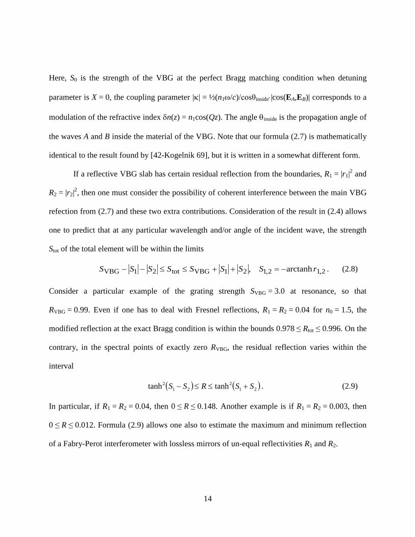
Here S0 is the strength of the VBG at the perfect Bragg matching condition when detuning
parameter is X = 0 the coupling parameter |κ| = frac12(n1ωc)cosθinsidesdot|cos(EAEB)| corresponds to a
modulation of the refractive index δn(z) = n1cos(Qz) The angle θinside is the propagation angle of
the waves A and B inside the material of the VBG Note that our formula (27) is mathematically
identical to the result found by [42-Kogelnik 69] but it is written in a somewhat different form
If a reflective VBG slab has certain residual reflection from the boundaries R1 = |r1|2 and
R2 = |r2|2 then one must consider the possibility of coherent interference between the main VBG
refection from (27) and these two extra contributions Consideration of the result in (24) allows
one to predict that at any particular wavelength andor angle of the incident wave the strength
Stot of the total element will be within the limits
212121VBGtot21VBG arctanh rSSSSSSSS minus=++leleminusminus (28)
Consider a particular example of the grating strength SVBG = 30 at resonance so that
RVBG = 099 Even if one has to deal with Fresnel reflections R1 = R2 = 004 for n0 = 15 the
modified reflection at the exact Bragg condition is within the bounds 0978 le Rtot le 0996 On the
contrary in the spectral points of exactly zero RVBG the residual reflection varies within the
interval
( ) ( )212
212 tanhtanh SSRSS +leleminus (29)
In particular if R1 = R2 = 004 then 0 le R le 0148 Another example is if R1 = R2 = 0003 then
0 le R le 0012 Formula (29) allows one also to estimate the maximum and minimum reflection
of a Fabry-Perot interferometer with lossless mirrors of un-equal reflectivities R1 and R2
15
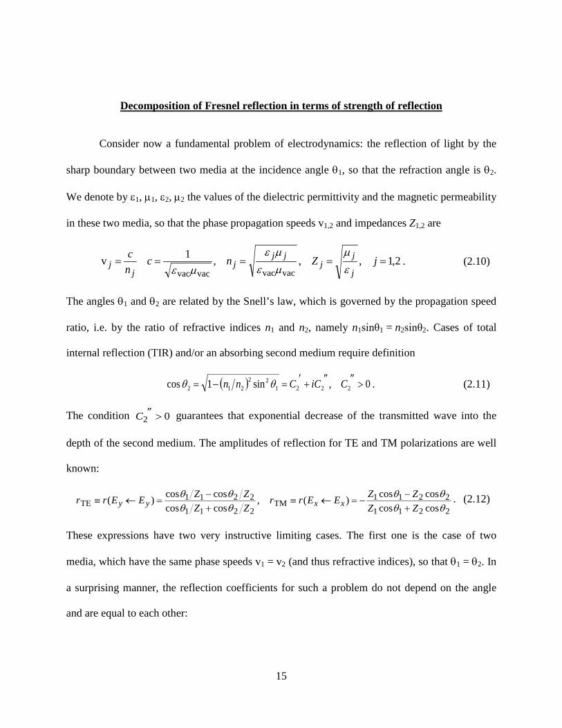
Decomposition of Fresnel reflection in terms of strength of reflection
Consider now a fundamental problem of electrodynamics the reflection of light by the
sharp boundary between two media at the incidence angle θ1 so that the refraction angle is θ2
We denote by ε1 micro1 ε2 micro2 the values of the dielectric permittivity and the magnetic permeability
in these two media so that the phase propagation speeds v12 and impedances Z12 are
211vvacvacvacvac
===== jZncnc
j
jj
jjj
jj ε
micromicroεmicroε
microε (210)
The angles θ1 and θ2 are related by the Snellrsquos law which is governed by the propagation speed
ratio ie by the ratio of refractive indices n1 and n2 namely n1sinθ1 = n2sinθ2 Cases of total
internal reflection (TIR) andor an absorbing second medium require definition
( ) 0sin1cos 222122
212 gtPrimePrime+prime=minus= CiCCnn θθ (211)
The condition 02 gtPrimeC guarantees that exponential decrease of the transmitted wave into the
depth of the second medium The amplitudes of reflection for TE and TM polarizations are well
known
2211
2211TM
2211
2211TE coscos
coscos)(coscoscoscos)(
θθθθ
θθθθ
ZZZZEErr
ZZZZEErr xxyy +
minusminus=larrequiv
+minus
=larrequiv (212)
These expressions have two very instructive limiting cases The first one is the case of two
media which have the same phase speeds v1 = v2 (and thus refractive indices) so that θ1 = θ2 In
a surprising manner the reflection coefficients for such a problem do not depend on the angle
and are equal to each other
16
12
12TMTE ZZ
ZZrrr Z +minus
=equiv= ∆ (213)
The other case corresponds to media 1 and 2 having exactly the same impedances Z1 = Z2 but
different propagation speeds n1 ne n2 In that case the reflection coefficients are equal (up to the
sign)
21
211vTMTE coscos
coscos)(θθθθθ
+minus
=equivminus= ∆rrr (214)
In particular there is no reflection at normal incidence for the pair of impedance-matched media
(stealth technology) Reflection strength values S = ndasharctanh r for these two limiting cases are
=
= ∆∆
1
21v
2
1coscosln
21)(ln
21
θθθS
ZZS Z (215)
Here is truly remarkable relationship which we have found One can produce the reflection
strengths STE(θ1) and STM(θ1) by simple addition (for TE) or subtraction (for TM) of the speed-
governed and impedance-governed contributions from (215)
)()()()( 1v1TM1v1TE θθθθ ∆∆∆∆ minus=+= SSSSSS ZZ (216)
and according to (26) r = ndashtanh S One can easily verify that the expressions (215) and (216)
reproduce the standard formulae (212) identically
Propagation of electro-magnetic waves in layered media
We have actually found (216) for ourselves not empirically but have derived the result of
additivity for reflection strength S directly from Maxwellrsquos equations Starting from here we
proceed with the tedious work of deriving the relevant formulae The idea is to formulate the
17
exact Maxwell equations for the layered medium in terms of two coupled amplitudes A and B
propagating with Pz gt 0 and Pz lt 0 respectively We consider the incidence plane to be the xz
plane for a monochromatic wave prop exp(minusiωt) incident upon a layered medium with the
properties being z-dependent only By θair we denote the incidence angle of the wave in air so
that
airairairairairairair cossinˆˆ θωθω nc
knc
kkk zxzx ==+= zxk (217)
The waves in a layered medium are naturally separated into transverse electric (TE) and
transverse magnetic (TM) parts We will write the electric and magnetic vectors of the two
polarizations using the appropriately normalized components ux uy uz and wx wy wz
respectively
[ ] )()(ˆ)(ˆ)()()(ˆ)(TE zZezwzwtzZezut tixikzx
tixiky
xx ωω minusminus +=minus= zxrHyrE (218)
[ ] )()(ˆ)()()(ˆ)(ˆ)(TM zZezwtzZezuzut tixiky
tixikzx
xx ωω minusminus =+= yrHzxrE (219)
Here and below we use the quantities k(z) p(z) g(z) f(z) defined by
)(cos)()()()()( 22 zzkkzkzpc
znzk x θω=minus== (220)
)(cosln21
)()(ln
21)(
)(1ln
21)( z
dzd
zkzp
dzdzf
zZdzdzg θequiv== (221)
Maxwellrsquos equations for the amplitudes of the TE polarization are
yxzyyzxxzxxzy uikikwguuikwgwwikwiku =minus+minuspart=minus+minuspart= (222)
they may be rewritten as
xyxzxyyz gwukpiwikwguu minus=part+=part 2 (223)
18
It is convenient to introduce the amplitudes A(z) and B(z) for TE polarization by the
definitions see Figure 1
)()(8
1)(
)()(8
1)(
air
air
TE
TE
minus=
+=
minus zwpkzu
kpezB
zwpkzu
kpezA
xyzik
xyzik
z
z
(224)
Figure 1 Notations for the incident A(z) and reflected B(z) waves in the approximation of infinitely wide plane
beams with account of the reflections from both boundaries z = 0 and z = L as well as the reflection by the VBG
The value of the z-component of the Poynting vector for any incidence angle at any point
z is
( ) 22 )()(41)( zBzAccHEHEzP xyyxz minus=+minus= (225)
θair
A(z)exp(ikairzz)
B(z)exp(ndashikairzz)
z = L z = 0
z
x
19
It should be emphasized that we have deliberately chosen to normalize the amplitudes A(z) and
B(z) such that the relationship (225) is valid at any point z One may further consider the
transformation (224) as a transition to ldquoSlowly Varying Envelopesrdquo (SVE) A(z) and B(z) It is
important to emphasize however that no approximations were made up to this point Indeed the
exact Maxwell equations for TE polarization are reduced by the coupled pair
( ) ( )( ) ( )
minusminus+
+minus=
=
minus
zzik
zikz
kzpiezfzg
ezfzgkzpiV
zBzA
VzBzA
dzd
z
z
air2
2air
TETE
TETE
TE
TE
)()()(
)()()(ˆ)()(ˆ
)()(
air
air (226)
A similar set of transformations may be done for TM polarization
2
yxyzxxz
xxzzxyyxzyyzx
gwikuwkpiguu
guuuikikwwikikugwwiku
minus=part+=parthArr
hArr+partminus=minus=minusminusminuspart=minus (227)
with the same parameters k(z) g(z) p(z) The amplitudes of coupled TM waves are
)()(8
1)(
)()(8
1)(
air
air
TM
TM
minus=
+=
minus zwkpzu
pkezB
zwkpzu
pkezA
yxzik
yxzik
z
z
(228)
Finally the exact Maxwell equations for TM polarization are
( ) ( )( ) ( )
minusminusminus
minusminus=
=
minus
zair2
2air
TMTM
TMTM
TM
TM
)()()(
)()()(ˆ)()(ˆ
)()(
air
air
kzpiezfzg
ezfzgkzpiV
zBzA
VzBzA
dzd
zik
zikz
z
z (229)
with the same parameters f(z) g(z) as in (221) The gradient functions f(z) (related to
propagation speed) and g(z) (related to impedance) enter as a sum (for TE polarization) or as a
difference (for TM one) into our coupled equations Sharp steps of n(z) and Z(z) yield our result
equations (216)
20
The notion of reflection strength was originally introduced by us for non-absorbing
media It is remarkable that the reflection by a sharp step with an absorbing second medium or
in the case of TIR are both described by S = ndasharctanh(r) and equations (215) and (216) are still
valid In particular the TIR regime corresponds to
( )
minus+=
= ∆∆ 11
22211v
2
1 cos1sinln21
4)(ln
21 θθπθ nniS
ZZS Z (230)
As expected |r| = |tanh(iπ4 + Re S)| = 1 for the case of TIR
Formalism of strength of reflection in other branches of physics
It is interesting to consider the reflection of longitudinal acoustic waves from the
boundary between two liquids which have densities ρ1 and ρ2 propagation speeds c1 and c2 and
therefore acoustic impedances Z1 = ρ1c1 and Z2 = ρ2c2 respectively A well-known expression
for the reflection coefficient for the waversquos pressure [31-Brekhovskikh 80 96-Landau 87] is
2211
2211longitud coscos
coscos)(ZZZZpprr
θθθθ
+minus
=larrequiv (231)
For this acoustic case we see again that the reflection strength is given by the sum of two
contributions
)()()](tanh[ 111longitud θθθ cZpp SSSSr ∆∆ +=minus= (232)
The Schroumldinger equation for the motion of an electron in a given Bloch band should
generally account for two kinds of spatial inhomogeneity see eg [97-Nelin 07] One of them is
U(r) [Joule] ie the spatial profile of the bottom of the Brillouin zone The other one must
describe m(r) [kg] ie the inhomogeneity of the coefficient 1(2m) in the parabolic
21
approximation E(p) = p2(2m) of the dependence of electron energy in the vicinity of the bottom
of Brillouin zone on the momentum p The corresponding hermitian Hamiltonian is
)(ˆ)(2
1ˆˆ rpr
p Um
H += (233)
which acts upon the wavefunction ψ Consider now the motion of the electron with fixed energy
E ie ψ(rt) = ψ(r)exp(ndashiEtħ) Then the stationary Schroumldinger equation takes the form
[ ] 0)()(2)(
1)( 2 =minus+
nablanabla ψψ rr
rr UEm
mm
(234)
If m(r) = const then equation (234) is reduced to the conventional Schroumldinger equation It is
convenient to introduce two quantities a ldquokinematic parameterrdquo k(r) in m ie the wavenumber
and a ldquodynamical parameterrdquo Z(r) in sm the analog of impedance by definitions
[ ] [ ])(2)(
)()()()()(21)(
rr
rrrrrr
UEm
kmZUEmk
minus==minus=
(235)
Numerically the parameter Z(r) coincides with the local value of the inverse group velocity
With these notations equation (234) takes the form
0)()()(
1)()( 2 =+
nablanabla ψψ r
rrrr k
kZkZ (236)
Equation (236) has two interesting limiting cases One of them is (236) with
Z = Z0 = const
0)()(
1)( 2 =+
nablanabla ψψ r
rr k
kk (237)
22
and we may call it the Z-Helmholtz equation to emphasize the condition Z = Z0 = const This Z-
Helmholtz equation was first introduced in the talk by Prof Zeldovich and Dr Tsai [98-Tsai 06]
in 2006
The other limiting case is when k = k0 = const but the impedance is coordinate-
dependent
0)(
1)( 20 =+
nablanabla ψψ k
ZZ
rr (238)
and for similar reasons (238) may be labeled as the k-Helmholtz equation Finally when both
Z = Z0 = const and k = k0 = const we come to standard Helmholtz equation 020
2 =+nabla ψψ k The
usual stationary Schroumldinger equation 0)(22 =+nabla ψψ rk (ie with ħkZ = m0 = const) is a certain
intermediate case between the Z-Helmholtz and the k-Helmholtz equations
The flux J [particles(m2s)] for a plane mono-energetic wave ψ = exp(ndashikr) in a
homogeneous part of the medium equals Zkk 22 )(v)( ψψ kkJ == The conservation law
which is valid as a consequence of the mono-energetic Schroumldinger equation (236) is
( )ψψψψ nablaminusnabla==
)(2)(0)(div
rrJrJ
mitt (239)
The problem of reflection for a one-dimensional stationary Schroumldinger equation
( ))(2)(0)()( 222
2
2zVEmzkzzk
dzd
minus==+
ψψ (240)
may also be solved by the coupled wave approach Namely we will assume for definiteness that
k2(z) gt 0 and introduce local amplitudes A(z) and B(z) by
23
mEkdzd
zkizkezB
dzd
zkizkezA zikzik 2
)()()(
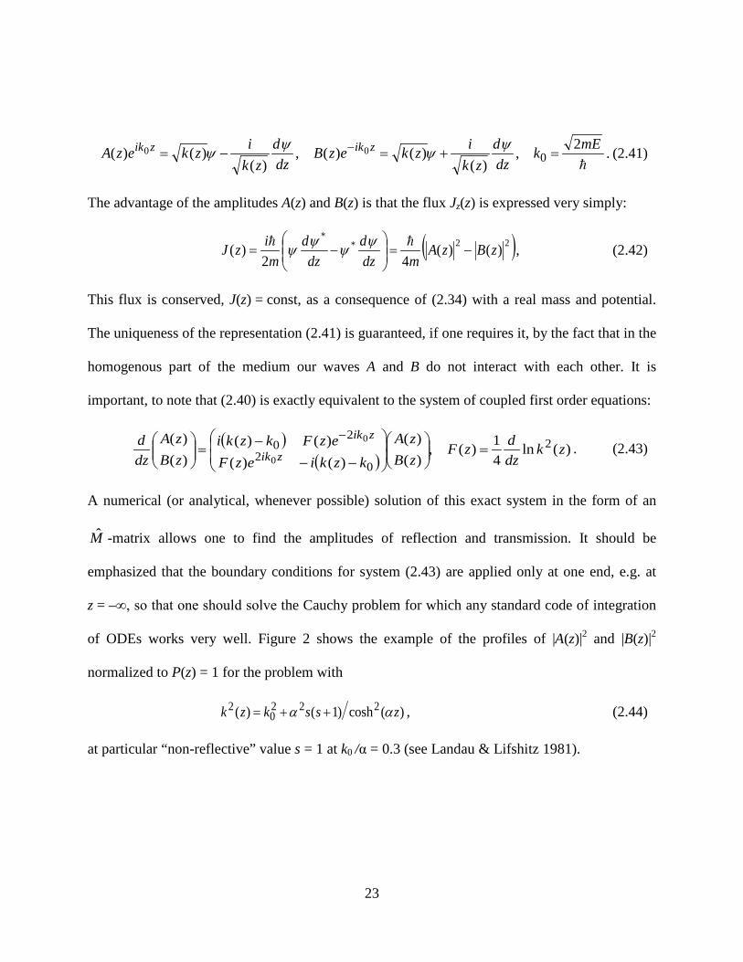
)()()( 000 =+=minus= minus ψψψψ (241)
The advantage of the amplitudes A(z) and B(z) is that the flux Jz(z) is expressed very simply
( )22
)()(42
)( zBzAmdz
ddz
dm
izJ minus=
minus=
ψψψψ (242)
This flux is conserved J(z) = const as a consequence of (234) with a real mass and potential
The uniqueness of the representation (241) is guaranteed if one requires it by the fact that in the
homogenous part of the medium our waves A and B do not interact with each other It is
important to note that (240) is exactly equivalent to the system of coupled first order equations
( )( )
)(ln41)(
)()(
)()()()(
)()( 2
02
200
0zk
dzdzF
zBzA
kzkiezFezFkzki
zBzA
dzd
zik
zik=
minusminusminus=
minus (243)
A numerical (or analytical whenever possible) solution of this exact system in the form of an
M -matrix allows one to find the amplitudes of reflection and transmission It should be
emphasized that the boundary conditions for system (243) are applied only at one end eg at
z = ndashinfin so that one should solve the Cauchy problem for which any standard code of integration
of ODEs works very well Figure 2 shows the example of the profiles of |A(z)|2 and |B(z)|2
normalized to P(z) = 1 for the problem with
)(cosh)1()( 2220
2 zsskzk αα ++= (244)
at particular ldquonon-reflectiverdquo value s = 1 at k0 α = 03 (see Landau amp Lifshitz 1981)
24
Figure 2 Solid lines potential well k02ndashk2(z) = ndash2cosh2z yielding non-reflection and incident beam energy
k02 = 009 Dashed lines fluxes |A(z)|2 and |B(z)|2 of counter-propagating wave function components
Solving for the reflection of waves for tilted incidence by a sharp boundary between two
media with different values (k1 Z1) and (k2 Z2) requires the analog of Snellrsquos law
2211 sinsin θθ kk = Here θ1 and θ2 are the angles of the momentum normal to the boundary in
the respective media The boundary conditions of continuity of wave-function ψ and of the
)()( Zkzpartpartψ yield the following expression for the reflection coefficient
=
=+=minus= ∆∆∆∆
2
1
1
2 ln21
coscosln
21tanh
ZZSSSSSSr ZkZk θ
θ (245)
similar to expression (216) which we have for TE electromagnetic wave
25
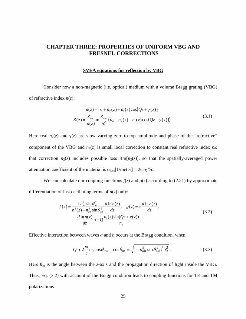
CHAPTER THREE PROPERTIES OF UNIFORM VBG AND FRESNEL CORRECTIONS
SVEA equations for reflection by VBG
Consider now a non-magnetic (ie optical) medium with a volume Bragg grating (VBG)
of refractive index n(z)
( )
( )( ))(cos)()()(
)(
)(cos)()()(
12020
vacvac
120
zQzznznnn
Zzn
ZzZ
zQzznznnzn
γ
γ
+primeminusminusasymp=
+++= (31)
Here real n1(z) and γ(z) are slow varying zero-to-top amplitude and phase of the ldquorefractiverdquo
component of the VBG and n2(z) is small local correction to constant real refractive index n0
that correction n2(z) includes possible loss iIm[n2(z)] so that the spatially-averaged power
attenuation coefficient of the material is αloss[1meter] = 2ωn2c
We can calculate our coupling functions f(z) and g(z) according to (221) by approximate
differentiation of fast oscillating terms of n(z) only
))(sin()()(ln
)(ln)()(lnsin)(
sin)(
0
1
21
2air
2air
2
2air
2air2
1
nzQzznQ
dzznd
dzzndzg
dzznd
nznn
zf
γθ
θ
+minusasymp
=minus
= (32)
Effective interaction between waves a and b occurs at the Bragg condition when
20
2air
2airinin0 sin1coscos2 nnn
cQ θθθω
minus=asymp (33)
Here θin is the angle between the z-axis and the propagation direction of light inside the VBG
Thus Eq (32) with account of the Bragg condition leads to coupling functions for TE and TM
polarizations
26
( ) 2cos)()()()(
cos
))(sin()()()(
in
in
1
θθ
γω
zfzgzfzg
zQzznc
zfzg
+asympminus
+minusasymp+
(34)
We see a natural result the coupling coefficient (which in optics is due to modulation of ε(z)
only) is smaller by factor ρ = (pamiddotpb) = cos2θin for TM polarization in comparison with the
coupling for TE polarization where that factor equals 1 Here pa and pb are unit polarization
vectors of the electric field for waves a and b The function sin(Qz+γ(z)) is equal to
( ) ( ))()(21)(sin ziiQzziiQzi eezQz γγγ minusminus+ minus=+ (35)
and a similar expression for the function sin(Qz+δ(z)) The slowly varying envelope
approximation which we will use later corresponds to keeping only one of the two exponential
terms from (35) in the coupling terms from Eqs (226) and (229) namely the terms which will
effect z-accumulated coupling As a result we get the equation for matrix )(ˆ zM expressing
values a(z) and b(z) through a(0) and b(0)
( )
( )
)()(
)()()(ˆ)(ˆ)(ˆ)(ˆ
air2
2air
TMTE air
air
minusminusminus
minus== +minus
minus
minus+
zzikiQz
zikiQzz
kzpiezi
ezikzpizVzMzVzM
dzd
z
z
κ
κ (36)
cos2)()(
cos2)()(TE
in
)(1
in
)(1
θωκ
θωκ
γγ zizi eznc
zeznc
zminus
minus+ == (37)
The interaction coefficients +κ and minusκ have indexes (+) or (minus) denoting the plusmn z-direction in
which the result of the corresponding scattering propagates These coefficients for TM
polarization are smaller by the polarization factor in2cos θρ = As written in Eq (36) the
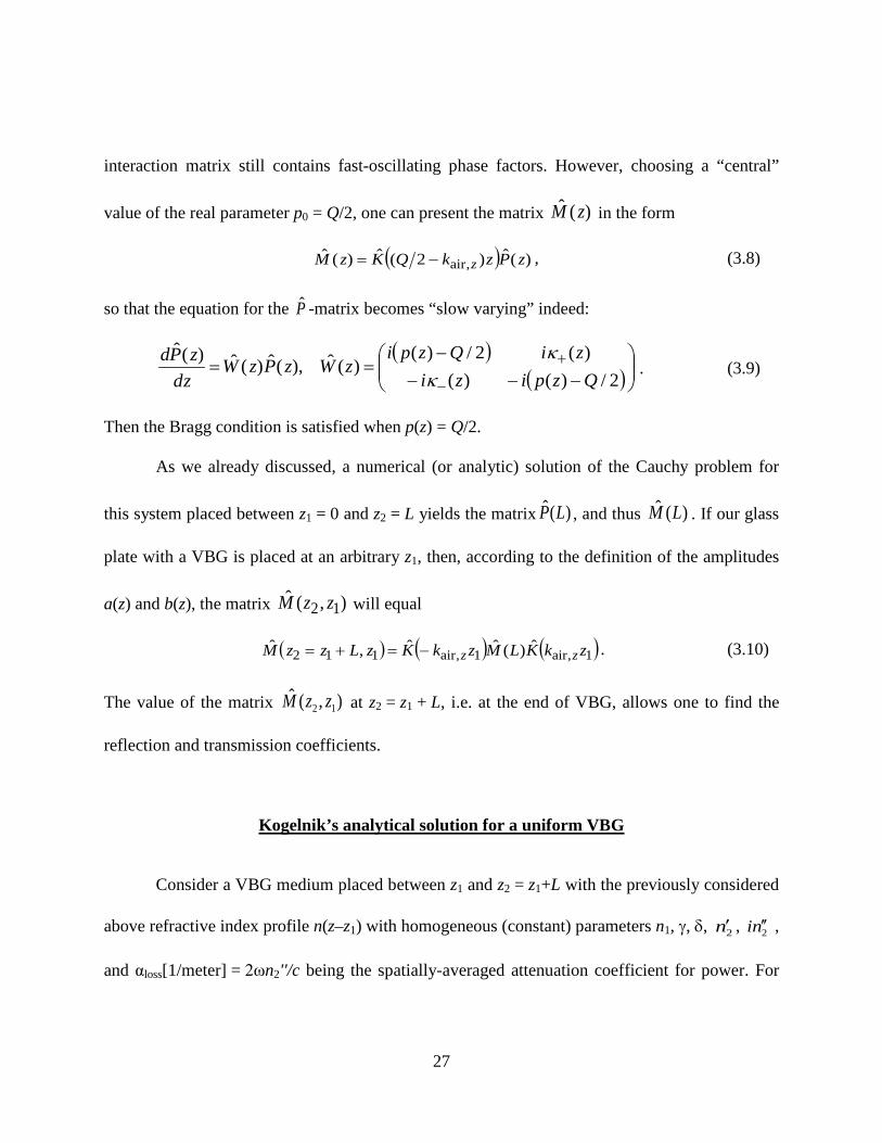
27
interaction matrix still contains fast-oscillating phase factors However choosing a ldquocentralrdquo
value of the real parameter p0 = Q2 one can present the matrix )(ˆ zM in the form
( ) )(ˆ)2(ˆ)(ˆ air zPzkQKzM zminus= (38)
so that the equation for the P -matrix becomes ldquoslow varyingrdquo indeed
( )( )
minusminusminus
minus==
minus
+2)()(
)(2)()(ˆ)(ˆ)(ˆ)(ˆ
QzpiziziQzpi
zWzPzWzdzPd
κκ
(39)
Then the Bragg condition is satisfied when p(z) = Q2
As we already discussed a numerical (or analytic) solution of the Cauchy problem for
this system placed between z1 = 0 and z2 = L yields the matrix )(ˆ LP and thus )(ˆ LM If our glass
plate with a VBG is placed at an arbitrary z1 then according to the definition of the amplitudes
a(z) and b(z) the matrix )(ˆ 12 zzM will equal
( ) ( ) ( )1air1air112 ˆ)(ˆˆˆ zkKLMzkKzLzzM zzminus=+= (310)
The value of the matrix )(ˆ12 zzM at z2 = z1 + L ie at the end of VBG allows one to find the
reflection and transmission coefficients
Kogelnikrsquos analytical solution for a uniform VBG
Consider a VBG medium placed between z1 and z2 = z1+L with the previously considered
above refractive index profile n(zndashz1) with homogeneous (constant) parameters n1 γ δ 2nprime 2ni primeprime
and αloss[1meter] = 2ωn2c being the spatially-averaged attenuation coefficient for power For
28
definiteness we consider here only the TE polarization The function p(z) from (221) in this case
will be assumed constant with a small positive imaginary part
( )
in
loss
in
2in0
2air
2air
220 cos2
cos
cossinθ
αθ
θωθω=primeprimeprimeprime+prime=
+asympminus+= ppipnn
cnnn
cp (311)
After that the W -matrix from (39) becomes z-independent and Eq (39) has the explicit
solution
sinhˆcosh1)(ˆˆ)(ˆˆ)(ˆ ˆ
GGLWGeLP
iiii
WzPWdz
zPd LW +==rArr
∆minusminus
∆==
minus
+κ
κ (312)
Prime+prime=sdot∆=primeprime+prime==minus=minusprimeprime+prime=∆ plusmnplusmnplusmnplusmnminus+ iXXLXLiLLSXSSGQpip 221 κκκ (313)
The dimension of ∆ is [1meter] In this manner the matrix )(ˆ LP becomes
minusminus
+=
minus
+
GGiXG
GGiS
GGiS
GGiXG
LP sinhcoshsinh
sinhsinhcosh)(ˆ (314)
Going back to Eqs (310) and (38) we obtain the expression for the matrix )(ˆ12 zzM
( )1airair1air12VBG ˆ)(ˆ2
ˆ)(ˆ zkKLPLQkzkKzzM zzz
minusminusminus= (315)
As a result the reflection coefficient for a VBG becomes
GGiXGGGiSe
PPe
MMrabr zik
bb
bazik
bb
ba zz
sinhcoshsinh)( 1air1air 22minus
=minus=minus==larr minusminus (316)
Formulae (31)-(36) of this Section 3 allow one to find the reflection coefficient even in the
presence of loss or gain Equivalent results in different notation were first derived in the
29
fundamental work of H Kogelnik [42-Kogelnik 69] We have re-derived them in our notation
which facilitate the subsequent account of Fresnel reflections
Imaginary detuning may be expressed via intensity an attenuation coefficient αloss
in
losscos2 θα LYX =equivprimeprime (317)
The relatively difficult part is to express the dimensionless quantity Re(X) via observables this
parameter signifies the detuning from the Bragg condition Suppose that the Bragg condition is
satisfied exactly at certain values of the incident angle θair0 at the wavelength λvac0 for definite
values of Q and n2 Then in the case of relatively small (but homogeneous) deviations from the
Bragg condition one gets
( )
minusminus++
minus=
0
2air0
2air
220
2air
inside2vac
vac
vac0
inside0 sinsin2cos
12
cos2)Re(nn
nn
QQLnX δθθ
θδ
λδλ
λθπδ (318)
While the appearance of expressions (311)-(318) is rather heavy their calculation by any
computer is quite straightforward Moreover accuracy of modern computers allows one to use
the procedure which is morally reprehensible but numerically admissible calculate
p(detuned) ndash p(Bc) as a small difference of two large quantities Such a procedure reduces the
risk of making a typo in Eq (318)
In the absence of loss or gain and with the modulation of real Re(n1) one gets
S+=(Sndash)=S0eiγ and Im(X) = 0 so that one can use the notion of reflection strength S and then the
reflection coefficient RVBG = R+ = Rminus = R becomes
30
sinharcsinh
cosh
sinhtanh)(
22000
20
22
222
XSGSSSSG
GSS
SXGGSabrR
minus===
=
minus==larr=
+minus+
(319)
Finally at the exact Bragg condition X = 0 and without loss the reflection strength S in (319) is
invac
10 cosθλ
π LnSS == (320)
which constitutes the most important and most simple formula of Kogelnikrsquos VBG theory
Influence of Fresnel reflections
For a sharp boundary positioned at zb the process of Fresnel reflection of the waves with
TE and TM polarizations is described according to (212) and (310) by the matrix M
)(ˆ)(ˆ)(ˆ)00(ˆ bairbairbb zkKSzkKzzM zz Σminus=minus+ (321)
1
2
1
2
1
2
2
1TMTE cos
coslnlncoscoslnln
coshsinhsinhcosh
)(ˆθθ
θθ
plusmnequivplusmn=
=Σ
nn
ZZS
SSSS
S (322)
At normal incidence to the boundary between two optical media with n1 and n2 the reflection
strength is the same for both polarizations S = frac12ln(n2n1) since Z = Zvacn For the particular
case n2n1 = 15 one gets S = 02027
Now consider the case of a VBG positioned between z1 and z2 = z1+L with a background
refractive index n0 this VBG is surrounded by air and nair = 1 For a VBG with boundaries the
transformation matrix M given by Eq (315) will be surrounded by two boundary matrices of
the type (321)
31
)(ˆ)(ˆ)(ˆ)(ˆ)(ˆ)(ˆ)(ˆ)00(ˆ 1air11air12VBG2air22air12 zkKSzkKzzMzkKSzkKzzM zzzz ΣminusΣminus=minus+ (323)
Here S1 and S2 are the strengths of reflections at the corresponding boundaries and the matrix
)(ˆ12VBG zzM is given by Eq (315) While the analytical expressions look quite heavy one has to
multiply the matrices given by explicit expressions only such a procedure is very simple for a
computer
In case of a perfectly lossless VBG one has to take into account the phase relationships
between contributions of the first boundary the VBG and the second boundary After a
summation of the arguments in the corresponding K -matrices the total matrix of VBG with
boundaries given by (323) will be
)(ˆ)(ˆ)2(ˆˆ)2)((ˆ)(ˆ)(ˆˆ 1air122air 0zkKSKPQLKSzkKM zXSz Σminus+Σminus= γγ (324)
220
0
0 sinhcoshsinh
sinhsinhcoshˆ
0XSG
GGiXG
GGiS
GGiS
GGiXG
P XS minus=
minusminus
+= (325)
with S0 and X defined in (313) and (319) We see that the character of the curve of reflectance
versus detuning depends on two phases γ and QL both related to the properties of the specimen
which contains the grating Their values fluctuate from one specimen to the other as a result of
manufacturing of VBG Quite often the specimens are coated with antireflection layers
Far from resonance when XgtgtS0 the matrix XSP 0ˆ will transform into a diagonal phase
matrix )(ˆ XK Then after summation of the phases between the boundaries we simplify the
matrix (324) to
in01air122air cos)(ˆ)(ˆ)(ˆ)(ˆ)(ˆˆ θωϕϕ Lnc
pLzkKSKSzkKM zz ==ΣΣminus= (326)
32
which describes an ordinary glass plate with interferometric properties defined by the phase
difference pL When this relative boundary phase is equal to an integer number m of π typically
large then the matrix )(ˆ ϕK is proportional to the unit matrix and the total reflection strength is
S = S1+S2 = 0 This corresponds to perfectly resonant transmission in a Fabry-Perot
interferometer based on reflections by the two boundaries If at some particular frequency or
angle point our VBG has zero strength eg if G = imπ with m being integer non-zero number
then XSP 0ˆ is proportional to the unit matrix and the boundary strength matrices Σ are separated
by the phase matrix so that the total reflectance will be defined only by the boundaries
Let us return to the VBG without background loss or gain and with boundaries of
different reflectances R1 and R2 in general case so that their reflection strengths are
2121 arctanh RS = respectively Multiplication of the corresponding matrices of the first and
of second boundaries of the VBG yielded the resulting matrix (324) The maximum and
minimum values of the total resultant strength are realized when the boundary terms are added or
subtracted from the VBG term
( )21VBGmin21VBGmax2tanh SSSSSSSSSR +minus=++== (327)
due to appropriate intermediate phases We consider formula (327) to be one of the important
results of the present work
Figure 3 was obtained by direct multiplication of the relevant matrices and then by
depicting all possible values of |Rtotal|2 at various combinations of the phases
33
-12 -10 -8 -6 -4 -2 0 2 4 6 8 10 1200
01
02
03
04
05
06
07
08
09
10
R
X
perfect ARC 03 ARC without ARC
Figure 3 Reflectivity R of a VBG with account of the interference of reflection from the VBG alone with two extra
contributions from the two boundaries of the specimen for all possible phase combinations Values of R are
between the dashed curves for Fresnel 4 reflections from bare boundaries and are between dotted curves for anti-
reflection coatings (ARC) at 03 each
We see that in the region of perfect Bragg condition X = 0 the reflectivity is not affected
strongly by the boundaries Even if one has to deal with Fresnel reflections R1 = R2 = 004 (for
n0 = 15) the modified reflection at the exact Bragg condition is within the boundaries
09779 le Rtotal le 09956 for RVBG = 09900 (S = 2993) On the contrary in the spectral points of
exactly zero RVBG where in (319) X2 = S02+m2π2 with integer nonzero m the residual reflection
varies within the interval
( ) ( ) ii RSSSRSS arctantanhtanh 212
212 =+leleminus (328)
34
In particular if R1 = R2 = 00400 then there is a 0 le R le 01479 Another example is if
R1 = R2 = 00030 then 0 le R le 00119 It means that there is a considerable advantage of the
coating the VBG with an anti-reflection coating
35
CHAPTER FOUR NON-UNIFORM VBGS
Propagation of EM waves in a non-uniform VBG
The requirements for angular and spectral selectivities of VBGs define their necessary
physical parameters such as thickness depth of modulation of refractive index etc The
properties uniformly modulated VBGs are well known from Kogelnikrsquos theory Standard
deliberately introduced non-uniformities are the apodization of refractive index modulation for
reducing secondary lobes in the reflectance spectrum and chirping the grating period to compress
short pulses Parameters of real fabricated gratings can vary from the required ones and can
significantly affect final properties The influence of undesirable non-uniformities was studied
for fiber gratings the presence of a spatial quadratic term in the background refractive index and
the observed asymmetries transmission spectrum of a fiber grating [65-Mizrahi 93] were
discussed An analysis of VBGs is more complicated because of the additional parameter the
angle of incidence
The propagation of electromagnetic waves in layered media can be formulated in terms
of counter-propagating waves A(z)exp(ndashiωt +ikz z) and B(z)exp(ndashiωt ndashikz z) with a convenient
normalization of Poynting vector Pz = |A|2 ndash |B|2 (225) The matrix relationship for wave
coupling in linear media is A(z) = MAAmiddotA(0) + MABmiddotB(0) B(z) = MBAmiddotA(0) + MBBmiddotB(0) In the
absence of losses the matrix M belongs to the group SL(11) and the amplitude reflection
coefficient for an element of length L is equal to r = r(AlarrB) = ndashMBA(L)MBB(L) = ndashendash2iηtanhS
where η is a phase parameter and S is the strength of reflection Matrix )(ˆ zM can be found from
equation
36
)(ˆ)(ˆˆ zMzVdzMd = (41)
and the Maxwell equations for a TE wave inside a reflective VBG with
n(z) = n0 + n1(z)cos[Qz+γ(z)] + n2(z) which lead to matrix V
sin1cossin)(
)2)(exp(cos2
)(0
20
2air
2airin
2air
2air
2
in
121122211
nnnznc
k
zikziiQzc
zniVVVV
z
z
θθθω
γθ
ω
minus=minus=
minus+==== (42)
And after certain phase transformations V goes to W
21
in
112
22
in
2in011 cos2
)(21
cos)(cos W
czniWW
dzdQznn
ciW ===
+minus
+=
θωγ
θθω (43)
The Bragg condition 02cos in0 =minusQcn θω is affected by the term dzdczn γθω 21
in2 )cos()( minus
which is angular-dependent for VBGs
Figure 4 represents an experimental transmission spectra from a fabricated narrow-band
reflective VBG fitted with a theoretical curve of a uniform grating with only a small additional
quadratic term in n2(z) of the refractive index n(z)
15524 15526 15528 15530 15532 1553400
02
04
06
08
10
Tran
smiss
ion
λ nm
Figure 4 Asymmetry in transmission spectra Solid line our experiment dotted line our model
37
The properties of a non-uniform VBG can be successfully simulated with a
corresponding step-matrix algorithm
Theory of light reflection from a chirped VBG
A chirped Bragg grating (CBG) allows for the stretching and subsequent compression of
a short laser pulse see experiments in [52-Liao 07] Such a grating may be characterized by two
parameters z-dependence of resonant vacuum wavelength of reflection dλresdz and coupling
coefficient κ of dimension mndash1 The profile of refractive index in such a CBG may be taken in
the form n(z) = n0 + n1(z)cos[Qz+γ(z)] At a given point z of the CBG the local Bragg condition
corresponds to a certain vacuum wavelength λres(z) which may be found from the equation
dzdQzn γλπ +=)(4 res0 (44)
In the approximation of relatively small deviations of λres(z) from some central reflection
wavelength λ0 = 4πn0Q the parameter dλresdz is related to the phase profile γ(z) according to
(44) by
2
2
0
20res
4 dzd
ndzd γ
πλλ
minus= (45)
Coupled equations in slowly varying envelope approximation (SVEA) for a
monochromatic wave [ ])exp()()exp()()exp()( ikzzBikzzAtitzE minus+minus= ω with wavelength λ0 have
the form
cnkcznzAei
dzdBBei
dzdA zizi ω
λπω
λπκκκ γγ
000
1)()( 2)()( ===minus== minus (46)
38
Is it possible to find an analytic solution of these equations in the approximation that
κ(z) = const and γ(z) = β(zndashz0)2 which corresponds to a homogeneously strong grating with
constant chirp )2( 020res ndzd πβλλ minus=
The reflection coefficient r for a monochromatic wave may be found by analytical
continuation of the coupled wave equations (46) into the complex plane of coordinate z The
result for reflectance is as follows
( )βπκ 22 exp1 minusminus== rR (47)
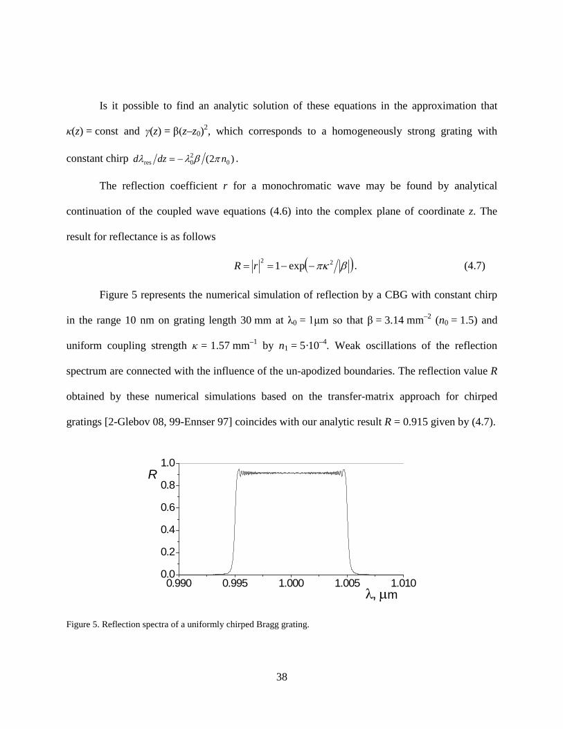
Figure 5 represents the numerical simulation of reflection by a CBG with constant chirp
in the range 10 nm on grating length 30 mm at λ0 = 1μm so that β = 314 mmndash2 (n0 = 15) and
uniform coupling strength κ = 157 mmndash1 by n1 = 5middot10ndash4 Weak oscillations of the reflection
spectrum are connected with the influence of the un-apodized boundaries The reflection value R
obtained by these numerical simulations based on the transfer-matrix approach for chirped
gratings [2-Glebov 08 99-Ennser 97] coincides with our analytic result R = 0915 given by (47)
0990 0995 1000 1005 101000
02
04
06
08
10
mλ micro
R
Figure 5 Reflection spectra of a uniformly chirped Bragg grating
39
Figure 6 shows the intensity distributions inside the CBG
0 5 10 15 20 25 30000025050075100125150
|B|2
|A|2
z mm
Figure 6 Intensity profiles |A|2 and |B|2 inside a chirped VBG for the central resonant wavelength
Thus the main result Eq (4) which was actually obtained in [100-Belai 06] allows one
to predict the parameters of CBG design for pulse stretching and pulse compression
40
CHAPTER FIVE RESONANT CAVITIES IN VBGS
Fabry-Perot resonator based on uniform VBGs
Consider a VBG made of two equally strong parts with each of them having the same
values SVBG Then the reflection action of the compound VBG depends on the mutual phases of
these two gratings If there is no phase shift Δγ between cosinusoidal modulations of refractive
index inside these two gratings then the combined VBG just acquires double the strength of each
grating Stot = 2SVBG However any intermediate shift 0ltΔγlt2π yields a narrow spectral
transmission peak (or reflection dip) to T = 1 (R = 0) The physical sense of this 100
transmission peak is similar to the 100 transmission peak of a Fabry-Perot resonator with flat
mirrors when the resonant condition is satisfied
In order to describe such a configuration of two VBGs we have to multiply consequently
matrices of elements with corresponding phases The experimental study was actually performed
with two uncoated identical reflective VBGs placed very close to each other with a small gap l
between them filled by an immersion liquid with the same background refractive index n0 as the
VBG The coordinates of first gratingrsquos boundaries are z0 = 0 and z1 = L and second grating is
positioned between z2 = L+l and z3 = 2L+l Spectral parameters X and strengths S0 are the same
for both gratings but the initial phases γ1 and γ2 are different The boundary reflection strength
from air to glass is Sb and the one from glass to air is ndashSb The transformation matrix determining
waves a and b after this compound system z gt z3 through values of a and b before it z lt 0 is a
product of matrices of two types (321) and (315) with )2(ˆˆ)2(ˆ)(ˆ 0γγ minus= KPKLP XS see also
(325) After simplifying the phase arguments it becomes
41
( )
22
2
)(ˆˆˆ2
ˆˆ)(ˆ)(ˆ)(ˆˆ)0()0(ˆ
)0()0(
213air32
21
1
b12b33
300
plQLzkQL
SKPKPKSKMba
Mzbza
z
XSXS
+minus+=∆minus=+
=minus=
Σ
∆minusΣ=
minusminus
=
++
γγγβγβγβ
βγββ (51)
For small size l of the gap the phase pl (or kl at normal incidence) is approximately the same for
all wavelengths in question We see that the reflection characteristics of this compound system
depend on three intermediate phases the phase shift Δγ between two cosinusoidal modulations in
VBGs contacted via immersion layer and two outside boundary phases β1 and β2
Our experimental collaborators from Prof L Glebovrsquos group have presented an
experimental demonstration of the coherent combination of two π-shifted VBGs in air The VBG
used for this demonstration were recorded inside PTR glass [2-Glebov 08] They have their
central wavelengths at 10634 nm thicknesses of 276 mm and refractive index modulation of
154 ppm middle-to-top They were recorded inside PTR glass without slant and the diffraction
efficiency was equal to 72 so S0 = 125 The two VBGs were fixed on mirror holders and one
holder was motorized with a piezo-electric transducer that allowed fine translation and fine angle
tuning The setup is shown in Figure 7 for the measurement of the spectral response using a
tunable laser having a 1 pm spectral resolution
VBG1
1050ndash1070nm
VBG2TunableLaser
Photo-diode
Photo-diode
VBG1
1050ndash1070nm
VBG2TunableLaser
Photo-diodePhoto-diode
Photo-diodePhoto-diode
Figure 7 Experimental setup for the coherent combination of two VBGs in PTR glass
42
Details of the experiment are described in our paper [2-Glebov 08]
The typical spectral dependence of the transmission filter is shown in Figure 8
Oscillations in transmission outside the resonance are due to the phase interplay between
uncovered Fresnel reflections and the secondary evanescent lobes of gratings This filter presents
a transmission higher than 90 with a bandwidth approximately equal to 25 pm (FWHM) and a
rejection width equal to 200 pm Rejection outside the resonance was better than 10 dB and can
be improved by combining it with an additional VBG or using VBGs with higher diffraction
efficiencies [101-Lumeau 06]
10630 10632 10634 10636 1063800
02
04
06
08
10
T
λ nm
Figure 8 Experimental transmission of two π-shifted VBGs
To illustrate the principle of phase matching between the two VBG the distance between
them was changed and the transmission for each distance was recorded in Figure 9abc One can
see that depending on the distance between the two VBG the resonance moved inside the main
43
lobe of the diffraction efficiency of the VBG When distance was optimized and the phase shift
Δγ set equal to π the resonance was centered in the middle of this lobe When this phase was
different from π resonance was shifted to the edge of the lobe
The solid curves at Figure 9 correspond to experimental data while dashed curves are
theoretical fits with optimized Δγ for these actual gratings
106330 106335 106340 106345 10635000
02
04
06
08
10106330 106335 106340 106345 106350
00
02
04
06
08
10106330 106335 106340 106345 106350
00
02
04
06
08
10
c
b
a
∆γ =410
∆γ =215
∆γ =π
T
T
T
λ nm
λ nm
λ nm
Figure 9 Spectral shift of resonant transmission due to phase shift Δγ between two grating modulations
We see reasonable agreement of the theory with experiment
44
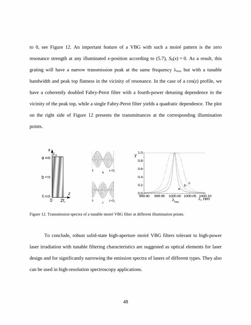
Resonant cavity in moireacute VBG
The spectral profile of a reflective VBG strongly depends on the actual profile of its
refractive index modulation By reducing the modulation amplitude at the ends of the grating the
secondary lobes of the reflection spectra are suppressed This apodization can be realized in
different ways One of them is based on the moireacute effect which occurs at imposing two periodic
oscillations with slightly different periods in media As a result the total recorded pattern has
carrier average spatial frequency while amplitude envelope varies slowly with spatial frequency
equal to half of the difference of the two partial frequencies namely
2)(2)()cos()cos(2)cos()cos( 212121 QQqQQQqzQzzQzQ minus=+==+ (52)
Such slow periodic variation of refractive index modulation has been implemented for fiber
Bragg gratings [102-Legoubin 91] The properties of moireacute fiber Bragg gratings were studied
before [103-Campbell 91 104-Everall 97]
Here we discuss moireacute structure recorded in bulk material Consider two uniform
gratings with equal amplitude slightly different vacuum resonant frequencies λ1 and λ2 and
wave vectors along z-axis recorded in the same medium Then total modulation of refractive
index is
2
sin)(
2
4)cos()()(
120
20
11
210
0
010
λλλλ
λπ
λλλλπ
ππ
minus=∆∆
==
+==+=
nt
tzNzn
nQQzznnzn (53)
45
here n0 is the background refractive index of material λ0 is the vacuum Bragg resonant
wavelength of the moireacute grating and n1(z) is the slowly varying envelope of modulation
amplitude with constant N1 and spatial semi-period tπ
Propagation of electromagnetic waves inside VBG may be formulated in terms of
counter-propagating waves A(z)exp(ndashiωt+ikzz) and B(z)exp(ndashiωtndashikzz) with kz = n0cosθinωc
where θin is the angle of propagation inside a VBG in the case of tilted incidence Coupled
equations for slowly varying envelopes A(z) and B(z) are the following
2cos
cos2)()()()( in
0
in
122 QcnD
cznzAezi
dzdBBezi
dzdA iDziDz minus==minus== minus θω
θωκκκ
(54)
where κ(z) is the coupling parameter and D is a z-independent parameter of detuning from the
Bragg condition D = 0 This condition is angular dependent so at skew propagation the resonant
wavelength is shifted to λres = λ0cosθin
The solution of the system (54) for linear media can be represented in matrix form by
)0()()0()()()0()()0()()( BzMAzMzBBzMAzMzA BBBAABAA +=+= (55)
In the absence of loss the matrix M belongs to the group SL(11) and with account of
boundary condition B(L) = 0 the amplitude reflection coefficient for an element of length L
equals
SRSeLMLMBArr iBBBA
22 tanhtanh)()()( =minus=minus=larr= minus η (56)
where η is a phase parameter S is the strength of reflection and R is the reflectance
The solution of (54) for a uniform grating is given by the well-known result of Kogelnik
Propagation of electromagnetic waves in non-uniform VBG in the general case with z-dependent
n0(z) n1(z) and Q(z) may be studied numerically only
46
If the coupling κ(z)endash2iDz is a real function eg at κ = κ D = 0 then the matrix M(z) for
system (54) can be found in simple way and we get the reflection coefficient r
intint ===
minus
==
LL
Ddzzn
cdzzSSir
SSiSiS
M0 10000
00
00
0)(
2)(tanh
coshsinhsinhcoshˆ ωκ (57)
We see that gratings with slow varying envelopes n1(z) with zero integral values S0 = 0
(57) demonstrate 100 theoretical transmittance at Bragg resonance Tres = 1 ndash R0 = 1 We have
such a situation for n1(z) from (53) with L = 2tπ This result can be interpreted as perfect
transmission through a Fabry-Perot filter of two identical reflective elements Figure 10
illustrates a moireacute filter with one sinusoidal period of n1(z) and its spectral transmittance
00 05 10 15 20 25 30-600
-400
-200
0
200
400
600
tπ 2tπ
n1(z)ppm
z mm
9996 9998 10000 10002 1000400
02
04
06
08
10
λres λ nm
T
Figure 10 Sketch of the envelope and simulated transmittance of a moireacute filter
The first moireacute VBG filter was fabricated in photo-thermo-refractive (PTR) glass by
sequentially recording two gratings with close resonance wavelengths near 1550 nm in the same
wafer Figure 11 presents experimental transmission spectrum of this coated sample with two
semi-periods of the moireacute pattern The bandwidth was 50 pm with 95 maximum transmittance
47
The estimated modulation of the recorded gratings is 120 ppm which is not high for PTR glass
Our simulations show that with higher modulation amplitudes it is possible to obtain bandwidths
of less than 10 pm
15465 15470 15475 1548000
02
04
06
08
10
Tran
smiss
ion
Wavelength nm
Figure 11 Experimental spectral selectivity of a moireacute VBG filter
The presence of transverse degrees of freedom in a VBG gives new possibilities for
operations with laser beams First of all a small rotation of the grating at an angle θair shifts the
spectral profile to a new Bragg wavelength according to
])(1[cos 2air
20air2
10in0res θλθλλ nnminusasymp= (58)
Even more attractive is the possibility to create VBG filters with non-trivial transverse profiles
when the vectors of the moireacute pattern q and the Bragg reflection Q are not co-linear Shifting the
grating perpendicularly within a laser beam or cavity will provide different filtering spectral
properties of such VBGs Consider a one-full-period moireacute VBG L = 2tπ with an envelope
n1(zx) that changes linearly from sin(z) to cos(z) when the VBG shifts in the x-direction from Lx
48
to 0 see Figure 12 An important feature of a VBG with such a moireacute pattern is the zero
resonance strength at any illuminated x-position according to (57) S0(x) = 0 As a result this
grating will have a narrow transmission peak at the same frequency λres but with a tunable
bandwidth and peak top flatness in the vicinity of resonance In the case of a cos(z) profile we
have a coherently doubled Fabry-Perot filter with a fourth-power detuning dependence in the
vicinity of the peak top while a single Fabry-Perot filter yields a quadratic dependence The plot
on the right side of Figure 12 presents the transmittances at the corresponding illumination
points
99990 99995 100000 100005 10001000
02
04
06
08
10
cb
a
λres
T
λ nm
Figure 12 Transmission spectra of a tunable moireacute VBG filter at different illumination points
To conclude robust solid-state high-aperture moireacute VBG filters tolerant to high-power
laser irradiation with tunable filtering characteristics are suggested as optical elements for laser
design and for significantly narrowing the emission spectra of lasers of different types They also
can be used in high-resolution spectroscopy applications
49
Bandwidth of resonant cavities in terms of strength of reflection
The most important characteristic of any spectral filter is its transmission spectral
bandwidth In the case of a symmetric cavity formed by two identical elements the transmission
peak profile has a Lorentzian form [105-Lipson 95]
LnLc
nXXF
T 20
00
002 2
11
λλλπωω minus
minus=minus
=sdot+
= (59)
where X is the dimensionless detuning (313) from resonant wavelength λ0 at which transmission
is 100 and F is a dimensionless parameter called ldquofinesserdquo characterizing the narrowness of
the transmission peak
Let us first re-derive an expression for the finesse of an ordinary Fabry-Perot filter in
terms of the reflection strength concept which we introduced earlier Suppose that we have two
surfaces with sharp reflection strengths plusmnSh (subscript ldquohrdquo stands for ldquohalfrdquo) placed at z = 0 and
z = L we have chosen strengths with opposite signs in order the reflection goes to zero when
these surfaces coincide that is when the separation L goes to zero A typical example of such a
filter is a glass plate with surface Fresnel reflection strength Sh = frac12lnn0 (215) for propagation
from air to glass with refractive index n0 If a transverse electric field propagating normally to
the reflective surface is represented in terms of counter-propagating waves
int+
int=
primeprimeminusprimeprimezz
zdznc
izdznc
i
ezBezAE 00
)()(
)()(ωω
(510)
then the wave amplitudes just after this surface at z = 0 will be expressed through a simple
propagation matrix
50
=Ξ
Ξ=
minus=+=SSSS
SBA
SBA
zz coshsinhsinhcosh
)(ˆ)(ˆ0
h0
(511)
An identical expression for another wave representation of the same electric field can be written
for the second reflective surface at z = L with strength minusSh in a coordinate system shifted along
the z-axis
LzzBAS
BAezBezAE
zz
zdznc
izdznc
izz
minus=
minusΞ=
int+
int=
minus=+=
primeprimeminusprimeprime~~
~)(ˆ~
~)~(~)~(~
0~h
0~
~)~(~)~(~
0
~
0
ωω
(512)
Comparing of the two different representations of the same electric field (510) and (512) we
can find a relation between two sets of counter-propagating waves
L
cin
Lc
inzLzz
L
z
ezBzB
ezAzALnzdznzdznzdznzdznzdzn ω
ω
0
0
)()~(~)()~(~
)()()()(~)~( 0000
~
0minus
+
=
=rarrminusprimeprime=primeprimeminusprimeprime=primeprime=primeprime intintintintint (513)
And finally we can write the propagation matrix for the total process of coherent reflection
from two surfaces of dielectric plate (dp)
( ) ( )
=
=ΞminusΞminus=
=
minus
minus=+=α
αωααα i
i
zLz ee
cLnKSKSKM
BA
MBA
00ˆ)(ˆˆ)(ˆˆˆˆ 0
hhdp0
dp0
(514)
Suppose at wavelength λ = 2πcω equal to some particular resonant value λ0 there is no reflection
at all which means that the total propagation matrix is a trivial unity-matrix 1 This is possible
when the K-matrix is proportional to the unity-matrix itself
0
0
0
0
0
0
210212ˆ
nmLmmLnLnK λπ
λπ
λπ
=rarr==rarrplusmn=
(515)
We have got a well-known result that 100 transmission of transparent dielectric plate occurs
when its thickness equals to an integer number of light half-waves in this medium
51
The reflective surfaces of a dielectric plate have strengths of opposite signs If we have
resonant cavity formed by identical non-absorbing reflective surfaces (rs) with the same
strengths Sh of the same sign separated by distance d then the total propagation matrix
( ) ( )c
dnSKSKMBA
MBA
zLz
ωβββ 0hhrs
0rs
0
)(ˆˆ)(ˆˆˆˆ =ΞΞminus=
=
minus=+=
(516)
will be a unity matrix when
0
021
21
0
0
0
0
2)(10)(2
10012ˆ
nmdmmdndnK z
λπλπσ
λπ +
=rarr=+=rarr
minus
plusmn=plusmn=
(517)
Therefore in the case of two identical reflectors the resonant transmission condition occurs when
the separation between them equals an integer number plus one half wavelength
Let us consider the propagation of a wave with a wavelength slightly different from the
resonant transmission wavelength λ = λ0 + ∆λ Then the propagation phase between the two
surfaces of a dielectric plate will be equal to α = πm + X where X is the detuning defined before
(59) and the total propagation matrix will be equal to
( ) ( ) ( ) ( )
( )
minusminus
+minus=
=ΞminusΞminus=ΞminusΞminus=
XSiXXSiXSiXSiX
XK
SXKSXKSKSKM
sin)2cosh(cossin)2sinh(sin)2sinh(sin)2cosh(cosˆ
)(ˆˆ)(ˆˆ)(ˆˆ)(ˆˆˆ
hh
hh
hhhhdp αα
(518)
It is easy to check that the expression for the propagation matrix for two identical reflective
surfaces will be the same )(ˆ)(ˆhdphrs XSMXSM = in the vicinity of resonant transmission with
the corresponding propagation phase β = π(m + frac12) + X with the same X but with separation d
(517) instead of thickness L (515)
52
Knowing the propagation matrix we can find amplitude transmission coefficient as the
ratio of the transmitted amplitude Az = L+0 to the incident amplitude Az = 0minus with the condition that
there is no incident of B-wave Bz = L+0 = 0 from (514)
BBBB
LAB
BB
BAAB
BBBAL
ABAAL
MMM
AAt
MM
ABr
BMAMBBMAMA 1ˆdet
0 0
0
0
0
000
000 ===minus==rarr
=+=+=
minus
+larr
minus
minuslarr
minusminus+
minusminus+ (519)
Finally the intensity transmission coefficient will equal
)2(sinhsin11
sin)2cosh(cos11
h2
22h
22 SF
XFXSiXMtT
BBABAB =
sdot+=
minus=== larrlarr (520)
In the literature [33-Hecht 01] we can find following expression for the finesse based on
the reflectivity R of one reflective surface element with an additional expression for the
maximum reflectivity of two coherently combined elements
2max2 )1(4
)1(4
RRR
RRF
+=
minus= (521)
It is easy to check that we got the same expression (516) if we take into account that the
reflectivity of one reflective element is equal to R = tanh2Sh Also when we substitute this
expression into the expression for Rmax we get natural result that the maximum reflectivity
corresponds to 2Sh double the strength of one element as it has to be according to the addition
law for reflection strength (24) which states that the maximum strength is equal to the sum of
moduli of two particular strengths
)2(tanh)1(
4)2(sinh)1(
4tanh h2
2maxh2
2h2 S
RRRS
RRFSR =
+==
minus=rarr= (522)
53
Thus we have presented expressions for the finesse F and the maximum reflectivity Rmax of a
Fabry-Perot filter formed by two thin reflective elements in new way through reflection strength
of each element Sh
In case of large finesse F gtgt1 in the vicinity of a transmission peak where the
transmission T is not much smaller than 1 in expression (520) we can substitute X for sinX
Finally from the value of dimensionless detuning at which transmission intensity equals its half
maximum (HM)
FX
XFT 1
21
11
HM2HM
=rarr=sdot+
= (523)
we will find the full width at half maximum (FWHM) of the transmission peak intensity in terms
of wavelength units
LnFFLnX
0
20
HMFWHM20
HM0HM
1212πλλλ
λλπ =∆=∆rarr=
∆minus= (524)
In the case of resonant cavity (C) formed by two surfaces with the same reflective strength Sh
the finesse is defined by (520) and therefore the width of the transmission peak is equal to
)2sinh(1
h0
20
0
20
FWHMC SLnLnF πλ
πλλ ==∆ (525)
Now let us calculate the bandwidth based on the corresponding finesse of a resonant
cavity based on two identical uniform VBGs with a mutual π-shift between their refractive index
modulations The results of experiments performed in Prof Glebovrsquos group for this compound
VBG system were discussed in the beginning of this chapter We presented the propagation
matrix for this cavity in (51) If we consider two strong VBGs with antireflection coating then
we do not need to complicate our consideration by additional boundary Fresnel reflections
54
Sb = 0 And then according to (51) the propagation matrix for two VBGs of thickness L each
with particular reflective strength Sh and with phase modulation separation between them γ
(γ1 = 0 γ2 = γ) will equal
sinhcoshsinh
sinhsinhcoshˆ
ˆ)2(ˆˆ)2(ˆ)2(ˆˆˆ
22
02
hh
XSGGGiXGGGiS
GGiSGGiXGP
PKPKXKMBA
MBA
XS
XSXSL
minus=
minusminus
+=
minusminus=
=
γγ
(526)
If the phase mismatch between the modulations of the two gratings is equal to γ = 2πm then the
phase matrix between the two gratings will be equal to the unity matrix multiplied by a factor plusmn1
namely 1)1()2(ˆ mK minus=γ and we will obtain the expected propagation matrix of a uniform VBG
of thickness 2L with total strength 2Sh On the contrary with phase mismatch equal
γ = 2π(m + frac12) we will get 100 transmission at the exact Bragg condition X = 0 and the
corresponding propagation matrix with omitting trivial first phase matrix factor )2(ˆ XK minus will
have the form
minusminus
+
minus
minus+=
GGiXG
GGiS
GGiS
GGiXG
GGiXG
GGiS
GGiS
GGiXG
m sinhcoshsinh
sinhsinhcosh
sinhcoshsinh
sinhsinhcoshˆ (527)
As we mentioned before the transmission of a lossless optical system is defined by its
propagation matrix element as 1|m22|2 see for example (520) In our case the matrix element
of interest is equal to
)(sinh2)2sinh(1sinhsinhcosh 322
2
2
22
2
22 XOXS
SXS
SiG
GSG
GiXGm +minusminus=minus
minus= (528)
55
Here we keep terms up to the second order of detuning in order to be able reproduce the
Lorentzian shape of transmission peak
2h
h4
U42U
222
sinh4)(1
11S
SFXOXFm
T =+sdot+
== (529)
According to (524) the bandwidth of a resonant cavity formed by two uniform VBGs with
mutual modulation π-shift will equal
h2
0
h20
0
20
UFWHMU sinh2
1SLn
SLnF π
λπλλ ==∆ (530)
In the experiment discussed before see Figure 8 the measured bandwidth was
∆λ = 25pm Let us compare this value with the theoretical one using the following data
mentioned before resonant wavelength λ0 = 10634 nm corresponding refractive index of PTR
glass n0 = 1485 thickness of each VBG L = 276 mm and strength Sh = 125 according to the
reflectivity R = tanh2Sh = 72 of each VBG Substitution of this data into (530) gives theoretical
value ∆λ = 21pm A small experimental widening of the bandwidth and a reduction of the peak
from 100 transparency can be naturally explained by small inhomogeneities inside the VBG
which results some blurring of transmission peak with corresponding spreading out of its width
and washing out perfect 100 resonant transmission in measured transmittance across aperture
The experimental results presented in Figure 9 show the wavelength shift of the
transmission peak with change of shift γ between the refractive index modulations of two
gratings in the vicinity of π-value For considered symmetric case γ = π the transmission peak
occurs at exact Bragg resonance with zero detuning X = 0 Now with arbitrary modulation
mismatch γ = π + δ we determine the wavelength detuning Xδ at which 100 transmission will
56
occur For these purposes let us expand matrix coupling waves inside VBG XSP hˆ (526) up to
the first order of detuning X
2
tanhˆˆ2
tanhˆ
)(tanh1coshsinh
sinhtanh1coshˆ
0
2
asymp
asymp+
minusminus
+
=
SSXKP
SSXK
XO
SSiXSSi
SiS
SiXSP
S
XS
(531)
As a result using the definition γ = π + δ and the additivity of arguments of phase matrices the
propagation matrix (526) will equal
+
+minus
+
+minusminusasymp
h
h0
h
h0
h
h
2tanhˆˆtanh
2ˆˆ
2tanh
2ˆ)2(ˆˆ
hh SSXKP
SSXKP
SSXKXKM SS
δπδπ (532)
As we saw before in (526) 100 transmission occurred when the argument of the phase matrix
)2(ˆ γminusK between matrices 0hSP with zero detuning was equal to minusπ2 which leads to the 100
transmission condition in the case of Equation (532) with γ shifted from π
πγδδδδδ minus==rarr=+minus
tanh20tanh
2 h
h
h
h
SSX
SSX (533)
So we get a first order dependence of the dimensionless detuning shift of the transmission peak
when γ varies from π by δ And according to the conversion factor from (524) the wavelength
shift of the transmission peak will equal
δπλ
πλλ δδ
h
h
SS
LnX
Ln tanh222 0
20
0
20 minus=minus=∆ (534)
57
Substitution of the parameters of the VBGs specified after Equation (530) into (534) gives the
same value of the peak position shift with mutual grating modulation mismatch
∆λδδ = 32 pmrad which was experimentally observed and presented in Figure 9
Bandwidth of a tunable moireacute filter
The main feature of a VBG is its high spectral selectivity or in other words small
rejection bandwidth This property together with its large operation aperture makes a VBG
recorded in PTR glass a unique robust spectral selective element for high power laser
applications As we discussed before spectral selectivity of a VBG-based element can be
improved by more than an order of magnitude by creating a resonant cavity with two uniform
VBGs with a mutual π-shift between their modulations Unfortunately this compound structure
is very sensitive to alignment which makes its implementation problematic for many practical
applications On the other hand the proposed moireacute filter is characterized by similarly improved
spectral selectivity but it is mechanically as robust as one uniform VBG because it is recorded
in one piece of glass As a result there are no problems with mutual alignment of both cavity
reflectors But in the case of the moireacute filter the precision required to record holographic
gratings is quite high because both gratings recorded in the same glass sample with a precise
small difference between their periods have to be uniform enough to produce a high quality
resonator Any non-uniformity like a small drift of the grating periods across the aperture which
is an undesirable small chirp will lead to washing out of the narrow transmission peak
58
Now let us derive an expression for the transmission peak bandwidth of a tunable moireacute
Bragg filter with a full envelope period of length 2Lπ The corresponding coupled wave
equations are
2)sin()sin()(20
2
2)()(0)()(0ˆˆ
M0hM1
012
2
λπϕπ
λπ
λπκ
κκ
πππππ LndzLzSLznznLz
Qnznzezi
eziV
BA
VBA
dzd
L
zi
zi
==+=lele
minus=∆=
minus=
=
int
sdot∆
sdot∆minus
(535)
For convenience we will adjust the wave amplitudes with appropriate detuning phase
dependence in order to have differential equations which are linear in terms of the detuning ∆
∆minus
∆=
rarr
+sdot∆minus=
BA
izzi
BA
dzd
BAzK
BA
~~
)()(
~~
~~
)4(ˆκ
κπ (536)
We will also rewrite the coupled equations in terms of a dimensionless variable ζ instead of the
z-coordinate
10
011~0110
)sin()()(ˆ
20~)(ˆ)(ˆ~~
)(ˆ~~
h21
0
0
ππ
π
πσϕςςκ
πς
ππςσςςςς
LXSLw
zL
iXwwBAw
BA
dd
sdot∆=
minus
=
+==
le=le+=
=
(537)
In order to determine the width of the Lorentzian peak we have to solve equation (537)
by sequential approximations up to the second order of detuning X in other words we have to
find the elements of the propagation matrix m at ς = 2π in quadratic form of X
)2(ˆ1)0(ˆ)(ˆ)(ˆ)(ˆ)0(~)0(~
)(ˆ)(~)(~
===
=
πςςς
ςς
ςς mmmwm
dd
BAm
BA
(538)
For this purpose we represent the propagation matrix power series with respect to the detuning X
59
[ ] 0)0(ˆ1)0(ˆ)(ˆ)()(ˆ1)(ˆ)(ˆ )21(0
)2(2)1(0 ==++= umuiXuiXmm ςςςς (539)
After substitution of this expansion into the matrix differential equation (538) we will get series
of matrix differential equations for each power of the detuning X
[ ] [ ]
ˆˆˆˆ~ˆˆˆˆ~ˆˆˆˆˆˆˆ
ˆ~ˆˆˆ~ˆˆˆˆˆˆˆˆˆˆ
ˆˆ1ˆ)~ˆ(ˆˆˆˆˆ1
ˆ
)1()1(
)1(0
10
)2()1(
0)2(
00
)2(
0)2(0
01
0
)1(
0)1(
00
)1(
0)1(0
000
)2(2)1(00
)2(2
)1(
0)2(2)1(0
ududumm
dudumumw
dudmu
dmd
mmdudmumw
dudmu
dmdmw
dmd
uXuiXmiXwdudX
dudiXmuXuiX
dmd
ςσ
ςσ
ςς
σς
σςςς
σςςς
==rarr+=+
=rarr+=+=
minus++=
minus+minus+
minus
minus (540)
The solution of the differential equation for the propagation matrix at zero detuning is the
result already discussed it has the form equivalent to (57)
( ) 1)2(ˆ)cos(cos2
)()(
)(cosh)(sinh)(sinh)(cosh
)(ˆˆˆˆ
0h
0
0000
=+minus=primeprime=
=rarr=
int πϕςϕςςκπ
ς
ςςςς
ςς
ςπ mSdLS
SSSS
mmwdmd
(541)
We see that the propagation matrix for a full 2π moireacute period length is a unity matrix as it should
be for 100 resonant transmission But we also will need its ς-dependent expression in order to
calculate the higher order terms on detuning which will then be used to calculate the matrix
element m22(2π) which defines transmission as T = 1|m22|2 according to (26)
[ ] )2()2(1)2()2(ˆ)2(ˆ11)2(ˆ )2(22
2)1(2222
)2(2)1( ππππππ uXiXumuXuiXm minus+=minus+= (542)
For the next first order term we will have
60
( ) ( )
21)(
)coscosh()cossinh()cossinh()coscosh(
)(2)2(ˆ
)()(
)()(1)(ˆ)(2sinh)()(2cosh)(
)()(
)()(1ˆ~ˆˆ
2
0
)cos(h0
hh
hhh0
)1(
00
00)1(0
10
)1(
hint
intintintint
prime=
minusminus
=
primeprimeminusprimeprimeminus
primeprimeprimeprime=
==
minusminus
==
+primeplusmn
minus
πϕς
ςς
ςς
ςπϕϕ
ϕϕπ
ςςςς
ςςςς
πς
ςςςς
ςςςς
πσ
ς
deSISS
SSSIu
dcds
dsdcu
SsSc
cssc
mmdud
S
(543)
where I0(Sh) is a zero-order modified Bessel function
Moreover for the approximation term proportional to X2 we have
( )
( ) )(2)2(ˆ)2(ˆ)2(ˆ
)()()()(01102ˆˆˆˆ
ˆˆˆˆ
21ˆˆ
21ˆˆˆˆ~ˆˆ
h2022
)1()1(21)2(
22
002
)1()1()1(
)1(
)1()1()1(
)1()1()1()1(
)1()1(
01
0
)2(
SIuuu
dcsdscduduu
dud
duduu
dud
duudu
dudumm
dud
=sdot=rarr
primeprimeminusprimeprime
=minus
minus+===
intint
minus
πππ
ςςςςςςπςς
ςςςςσ
ςςς
(544)
As a result we get the matrix element of interest from (543-44)
)()(2)coscosh()(21)2( 32h
20hh022 XOiXSIXSSiIm sdot+minusminus= ϕπ (545)
which defines Lorentzian shape of the moireacute filter transmission peak with a finesse parameter FM
)cos(sinh)(4)(1
1)2(
1h
2h
20M42
M2
22
ϕπ
SSIFXOXFm
T =++
== (546)
According to (524) the bandwidth of the moireacute filter is equal to
)cossinh()(21
hh00
20
0
20
MFWHMM ϕπ
λπλλ
SSLInLnF==∆ (547)
The phase shift ϕ = π2 in the moireacute 2π-period corresponds to the cosine-profile of the
moireacute modulation envelope as opposed to the initial sine-profile with ϕ = 0 And in this case of
a cosine-profile the parameter FM is going to zero (546) with ϕ = 0 which leads to an infinite
61
bandwidth according to (547) In order to have a physically reasonable value of the bandwidth
we have to take into account next non-zero power term on detuning X4 in (546)
Let us calculate the approximation up to fourth power for a particular cosine profile
( )
432ˆˆ~ˆˆˆ~ˆˆ
sin)()(cosh)(sinh)(sinh)(cosh
)(ˆˆˆˆ
0)0(ˆ1)0(ˆ)(ˆ)(1)(ˆ)(ˆ
0110
cos)(ˆ)(ˆ~)(ˆ)(ˆ
)1(0
10
)(
01
0
)1(
h21
0000
)(0
4
1
)(0
h21
00
===
=
=rarr=
==
+=
=+=
minusminusminus
=sum
jummdudmm
dud
SSSSSS
mmwdmd
umuiXmm
SwmiXwmdd
jj
c
j
j
jj
cc
σς
σς
ςςςςςς
ςς
ςςς
ςςςσςςς
(548)
Similar to (543) in the first order we have the following
( ) ( )( ) ( )
10
01)(2)2(ˆ)()2()()(
)(ˆ)(ˆ)(ˆ1111
ˆ11
11ˆ)(
)(ˆ)(ˆ)(2cosh)(2sinh))(2sinh)(2cosh1ˆ~ˆˆ
h0)1(
h00
)1(sin21
01
0
)1(
h
minus
==primeprime=
+=rarr
minusminus
=
minusminus
==
+=
minusminus
==
plusmnplusmnplusmn
minus+plusmnplusmn
minus+minus
int SIuSIIdI
IcIrucre
crSS
SSmm
dud
S
ππςςες
ςςςςε
ςεςεςς
ςςπ
σς
ς
ςπ (549)
Expressions for second order are
( )( )
)()()()(ˆ2)(ˆ2)(ˆ
1111
ˆˆˆ1111
ˆˆˆ0ˆˆ
)()(ˆ2)()(ˆ2ˆˆˆˆˆˆˆ
0 0
)2(
21
2122
)1()1()2(
int int primeprimeprimeprimeprimeprime=+=
rarr
==
minus
minus====
+=++==
prime plusmnplusmnminus++minus
+minusminus+minus+minus+
ς ςςςςεςεςςςς
ςςεςςεεεςς
ddIIdIpu
rcpcrdcr
IpIdIcIrcrudud
dud
(550)
The diagonal matrix elements of the second order matrix term are easy to calculate
)(2)2()()(2)(2)(2 h20
)2(221100
)2(22
)2(11 SIuddIIuu =primeprimeprimeprimesdotprimeprime=+== intint +minus+minus+minus πςςεςςεςς
ςς (551)
62
but calculation of the off-diagonal matrix elements is much more challenging We present here
final the result from the detailed derivation which can be done by the approach based on
differentiation parameter under the integral sign
suminfin
=
++minus+minus
+=minus==
02
12hh0)2(
2112)2(
21)2(
12 ])12[()(4)2()(2)(2
k
k
kSSIuIIuu
ππςς (552)
The third and fourth order approximation terms are expressed as
( ) ( )
( ) ( )
)()()()(ˆ8)(ˆ8)(ˆ
ˆ8ˆ8ˆˆ4ˆˆˆˆˆ
)2()2()()()()(ˆ4)(ˆ4)(ˆ
ˆ4ˆ40ˆˆˆˆ
ˆ2ˆˆˆ2ˆˆˆˆ2ˆˆˆˆˆ
0
)4(
)3()1()4(
0
)3(
)2()1()3(
int
int
primeprimeprime=+=
+=++==
=primeprimeprime=+=
+=====
=++==
plusmnplusmnplusmnplusmnminus+minus++minus+minus
minus+minus++minus+minusminus+minus+minus+minus+
minus+minus+minus+plusmnplusmnplusmnplusmnminus+minus+minus+
minus+minus+minus+minus++minusminus+
ς
ς
ςςςεςςςς
εεεεςς
ππςςςεςςςς
εεεεςς
dIIIdIpu
IdIpIcIrcrudud
dud
IIdIIIcIru
IcIrpcdr
cdcrprIdIpcrudud
dud
(553)
Now we can write the total expression for the propagation matrix of a moireacute filter with a
cosine profile up to the fourth power of detuning
1111
)2(81111
)2(8
1001
)2(8)(2)2()2()(2
1001
)(21ˆˆˆˆ1)2(ˆ
44
3
h20
)2(12
)2(12h
202
h0)4(4)3(3)2(2)1(
minus
minus+
+
+
minus
minus
minus
minus
minus
+=+minusminus+=
minus+minus++minus+minus
+minus+
ππ
ππ
π
π
IXIX
IiXSIu
uSIX
SiXIuXuiXuXuiXm
(554)
The square of the diagonal matrix element |m22(2π)|2 which defines the transmission peak
shape up to the fourth power of detuning is equal to
( ) 4h0h
40
222 )]2()2([16)2()(32)(41)2( XIIISISIm ππππ minus+minus++minus+minus+minus+ ++minus+= (555)
63
On the other hand the determinant of the propagation matrix for an arbitrary lossless
element has to be equal unity according to (23) with ψ = 0 So the calculation of the determinant
of the current propagation matrix (554) up to fourth power of detuning X4 gives an expression
which has to be equal one without any functional dependence on the parameters such as
detuning which means that the coefficients at detuning powers have to be identically zero
( ))]2([][16)(32)(4
1)]2([][16)(32)(41)2(ˆ2)2(
12)2()2()2(h0h40
42)2(12)2()2()2(h0h
40
2
π
ππ
πππ
πππ
uIIISISI
XuIIISISIm
=++minusrarr
=minus++minus+=minus+minus++minus+minus+minus+
minus+minus++minus+minus+minus+
(556)
The last relation in (556) significantly simplifies expression (555) As a result with account of
the value of the off-diagonal elements (552) we get an analytical expression for the
transmission peak profile of a cosine moireacute filter
1
1)2(
1
])12[(
)(4)2()]2([1)2(
4222
02
12hh0)2(
122)2(
1242
22
XHmT
kSSIuuHXHm
k
k
sdot+==
+==sdot+= sum
infin
=
+
π
ππππ
(557)
Such detuning dependence of the transmission peak profile has a much more flat-topped peak
shape than a regular Lorentzian peak profile It can be explained as the equivalence of a cosine
moireacute filter to a new physical transmission element ndash the double coherent cavity
Finally the wavelength full width at half maximum (FWHM) of this doubly coherent
moireacute (DCM) cavity transmission peak can expressed using the half width (HW) detuning
parameter according to (557)
64
])12[(
)(22
2])12[(
)(2121)(
1
02
12hh0
0
20
HWHM0
20
HWFWHMDCM
020
HW
1
02
12hh0
4HWHMHW
minusinfin
=
+
minusinfin
=
+
+sdot==∆=∆
∆minus=
+==rarr=
sum
sum
k
k
k
k
kSSI
LnX
Ln
Lnk
SSIH
XXT
ππλ
πλλλ
πλλ
π
ππ
π
(558)
To the best of my knowledge the theory of doubly coherent cavities is not well-
researched We think such cavities could be useful for some quantum optics or quantum
information applications While regular Fabry-Perot cavities are widely available the fabrication
of double cavity looks to be challenging The realization of such cavities based on a particular
moireacute cosine profile in principle can be a realistic way to implement a doubly coherent cavity
65
CHAPTER SIX MULTIPLEXED VBGS IN PTR GLASS
Properties of PTR glass
Photo-thermo-refractive glass is a photosensitive material developed [106-Glebov 02] for
the recording of volume holographic elements such as high-efficiency volume Bragg gratings
[49-Efimov 04] UV laser radiation causes a chemical recombination processes in the
compounds of this glass after subsequent thermal developing the permanent change of refractive
index of the glass matrix can be achieved up to δn asymp 10ndash3 equiv 103ppm Robust optical elements
made of this glass are characterized by low absorption and scattering in the visible and IR
spectral ranges and a high tolerance to operating laser irradiation VBGs recorded in PTR glass
are widely used for spectral narrowing of radiation from laser cavities they are promising
candidates for the implementation of spectral beam combining (SBC) In particular we discuss
in this chapter PTR glass for recording transmitting non-diffractive phase elements
PTR glass is a unique photosensitive material for recording optical phase plates
Homogeneous optical flats with apertures as large as 100times100 mm2 and fluctuation of the
refractive index of a few ppm across the aperture can be fabricated in PTR glasses The change
of the average refractive index across the PTR glass aperture (xy) allows one to change the
optical path length along z-coordinate As a result different phase shifts φ(xy) can be achieved
and the phase of the transmitted beam can be modulated across its aperture In addition PTR
glass has a broad transmission spectral range high mechanical chemical and thermal stability
and good tolerance to high power radiation
66
Let us consider a PTR glass window of constant thickness L This plate will be used for
recording a phase plate operating at wavelength λ Suppose that we want a relative phase shift of
Δφ = 2π between the different aperture points It can be achieved with relative variation Δn(xy)
of the refractive index of the glass in these aperture points If the refractive index depends also
on coordinate z then Δn(xy) is the average value along the thickness so
22 22 LnnLkL λ
λππϕ ππ =∆rarr∆=∆==∆ (61)
Thus the variation of the recorded refractive index change across the aperture for a plate
of thickness L = 3mm and operating wavelength λ = 106μm has to be Δn2π = λL = 355ppm
This value is within the range of the linear photosensitivity of PTR glass see Figure 13
Researchers in the glass fabrication laboratory of Prof L Glebovrsquos group have measured this
experimental curve
0
100
200
300
400
500
600
700
0 02 04 06 08 1
Dosage Jcm2
RIC
ppm
Figure 13 Photosensitivity curve of PTR glass depending on the exposure dosage
67
The process of creating local refractive index change in PTR glass is described in detail
in [107-Efimov 03] It consists of two major steps first a PTR glass sample is exposed to
radiation using for example a He-Cd laser and then the sample is thermally developed at a
temperature above the glass transition temperature for several hours
The change of the local refractive index of the recorded phase plate is determined by the
UV dosage at this aperture point Therefore in order to create a desirable distribution of the
phase variation φ(xy) across aperture it is necessary to control the spatial distribution of the
UV dosage according to the curve of Figure 13
Probabilistic amplitude masks for phase plates in PTR glass
In general an amplitude mask with a gradually varying transmittance is required for
recording an arbitrary phase plate During the digital generation and printing process amplitude
masks often have small regular structural elements ldquodotsrdquo with sizes larger than the wavelength
of UV exposure In this case laser radiation transmitted through such an amplitude mask has an
additional undesirable diffraction pattern from those structural elements For example ordinary
lithographic methods allow one to create amplitude masks with only binary
transparentnontransparent areas Gradual variation of the transmittance across the mask aperture
can be achieved by creating small areas with a corresponding probabilistic distribution of their
binary transmittance Figure 14 demonstrates an amplitude mask of such a probabilistic type
68
Figure 14 The central area of a probabilistic amplitude mask for recording vortex phase plate (left) and the local
area with a filling factor 025 (right)
If the size of small micro-areas is larger than the wavelength then the final recorded
coherent intensity radiation pattern inside the PTR blank will demonstrate a parasitic highly
divergent diffraction structure at the operating wavelength of the fabricated phase plate There
are several approaches to eliminate this parasitic diffraction pattern from microstructures First
when contact recording is used an incoherent source eg a lamp can be used as the source of
recording radiation instead of a UV laser The spectral filter can be used to eliminate the
unnecessary part of the spectrum restricting it to the spectral range in which the PTR glass is
photosensitive and thus reducing heating An alternative method consists in using recording
UV laser with small translational or angular relative shifts varying with time between the
master amplitude mask and the PTR blank in order to average the coherent intensity distribution
during the contact recording process
Besides the contact recording process imaging systems can be applied In this scheme
the amplitude mask intensity distribution is imaged on a PTR glass blank while high-angular
diffraction frequencies caused by the small structural elements are eliminated using a spatial
filter As a result the PTR glass blank is illuminated by a cleaned-up smooth intensity
69
distribution One optical setup of such type is a classical 4f-system This system consists of two
lenses separated by a distance equal to the sum of the two focal lengths different in general case
A pinhole is added in the beam path between the two lenses (ie at the image focal plane of the
first lens or the object focal plane of the second lens which overlap) The amplitude mask is
located in the object focal plane of the 1st lens while the recording material is placed in the image
focal plane of the 2nd lens see Figure 15 Finally this optical system is illuminated by a
collimated uniform beam In this setup the mask is imaged using the two lenses in the PTR glass
window and the aperture ldquofilters outrdquo the high angular diffraction frequencies from small
printing ldquodotsrdquo on the amplitude mask
Figure 15 4f optical system for spatial filtering
The method of spatial filtering was applied to record a phase mask with an azimuthally
increasing phase shift The experimental part of this work was done in the holography laboratory
of Prof L Glebovrsquos group and it is not discussed in this dissertation
To conclude the refractive index change across the aperture can be controlled using two
parameters the dosage of UV exposure and the thermal treatment durationtemperature Thus
after recording the phase plate the only controlling parameter is the thermal duration It is
f f f f
Amplitude mask Lens1 Stop
aperture Lens2 PTR glass plate
70
possible to develop the sample at a given temperature and for a given time and to control this
phase plate after such a heat-treatment If the local refractive index change of the exposed area is
less than the required change and the phase change is also less than the required change then the
phase plate can be additionally thermally developed in order to make the local phase shift larger
To the contrary if the refractive index change that was achieved is larger than the required one
and therefore the phase change is larger than the required one it is possible to decrease the phase
change to the required one by finely polishing the phase plate Finally for phase plates that are
developed for specific operational wavelengths after fabrication their surfaces can be anti-
reflection coated to reduce Fresnel reflection losses
Slanted reflective and transmissive VBGs
We have previously discussed VBGs of the reflective type which can be described by
one-dimensional coupled equations for counter-propagating waves The same theoretical results
are applicable for fiber Bragg gratings (FBGs) The main advantage of reflective VBGs in
comparison with FBG used for high-power lasers is that their large aperture and as a result the
couplers are unnecessary that reducing coupling losses Another additional important feature of
VBGs is the possibility of tuning the Bragg condition by changing the angle of incidence upon
the grating Another possibility for tuning is the moireacute filter in VBG with the recorded pattern
shown in Figure 12 which conserves the resonant wavelength of the transmission peak with a
transverse shift of the illumination point along the aperture while still allowing for a change in
the shape and width of the transmission peak
71
The next step is to consider volume Bragg grating geometries which cannot be realized
in the case of FBG They are transmissive gratings characterized by high angular selectivity and
volume elements with multiple gratings recorded simultaneously mostly reflective VBGs with
different slanted angles between Bragg wave vectors and normals to grating surfaces The Bragg
diffraction processes again can be efficiently described by coupled wave theory ndash actually with
equations of the same type and with slightly different more generalized boundary conditions
Previously we used coupled wave equations derived for layered media with only z-
dependent properties Now consider a VBG with its refractive index uniformly modulated along
the grating vector Q for an arbitrary orientation
)cos(2)()cos()( 1020
20110 QrrQrr nnnnnnnnn +asympltlt+= (62)
We can rederive the coupled equations from the Helmholtz wave equation for the electric
field presented as a superposition of two waves A(r) and B(r) with different polarizations and
wave vectors approximately satisfying the Bragg condition
QkkkeeEErE rkrk minus===+==+nablasdotnabla ABBA
iB
iA kBeAenk BA 20)()( 0
220 λ
π (63)
With the standard assumption of slow variance for A and B the second derivatives can be
neglected so
0))(()(2)(2 10
20 =+++nabla+nabla minus rkrkQrQrrkrk eekeke BABA i
Bi
Aii
Bi
BAi
A BeAeeennkBeiAei (64)
According to the Bragg condition from (62) we keep only two corresponding terms after
expanding the brackets in (64) and finally we will get two separate coupled equations with
slow spatially oscillating factors
72
2)(
)()( 1
2
2 Qkkeemm
Dr
Dr minusminus===
=nabla=nabla minus
BABAi
B
iA Dpn
AeipBBeipA
λπκ
κκ
(65)
The polarization factor p is equal to one for TE polarization and for TM polarization coupling is
reduced by the cosine of the mutual angle between the wave vectors In particular for TM waves
propagating in orthogonal directions there will be no coupling
Now consider a reflective VBG of thickness L with vector Q in xz-plane with an angle γ
relative to the normal of the front face of the VBG plate see Figure 16 For definiteness
consider only TE incident and reflected plane waves which in particular means that the
amplitudes A and B are constant outside the VBG and at the boundaries of the VBG
Figure 16 Beam geometries of slanted reflective and transmissive VBGs
If the boundary conditions for the amplitudes do not depend on coordinate x then it is
natural to look for only z-dependent solutions A(z) and B(z) of the coupled equations (65)
After that the only explicit functional dependence on the x-coordinate will remain in the
oscillating factor and in order to eliminate it the phase-matching condition Dx = 0 must be
satisfied It means that for a certain incident angle θA the direction of the reflected wave will be
73
determined from this phase-matching boundary condition Finally we come to the following
system of equations for the amplitudes of the incident and reflected waves
( ) 0coscos
)coscoscos(
cos
cos
)sinarcsin(sin0)sinsinsin(
)cos0(sin2
)cos0(sin)cos0(sin
22
211
2
2
21
=minusrarr
minus+==
=minus
=
minus=rarr=minusminus=
=ltminus==
minus
BAdzd
QkkDn
AeidzdB
BeidzdA
kQQkkD
BA
BAz
ziDB
ziDA
ABBAx
BABBBAAA
z
z
θθ
γθθλπκ
κθ
κθ
γθθγθθ
γγπθθθθθ Qkk
(66)
All of the angles θA θB γ are defined inside the VBG glass plate while outside the VBG
the propagation angles of the waves in air can be recalculated according to Snellrsquos law In order
to avoid consideration of this trivial extra step we can assume that the grating is surrounded by a
refractive-index-matched liquid for example
The coupled wave equations (66) can be easily transformed to linear equations with
constant coefficients by the following substitution for wave amplitudes After that we can write
a solution very similar to the already discussed one and with the boundary condition of
no-incoming wave B into the VBG we can get expression for the diffraction efficiency
cosh
sinhcos
cos0
~
sinhcosh1
coscos~~
~
coscos
22222
222
20
20
20
20
022
2222
SXXSXS
a
b
A
BRb
LDXLS
ba
XSXS
iXiSiSiX
XSba
iDiiiD
ba
dzd
beBaeA
A
BLz
zzLz
BAz
z
BziD
AziD
z
z
minusminus
minus===rarr=
==
minus
minus
minusminus
+minus=
rarr=
minusminus
=
rarr
==
=
==
minus
θ
θ
κ
θθκκ
κκ
θθ
(67)
Such a reflection spectrum was discussed before see the solid line (no additional Fresnel
corrections from boundaries) in Figure 3
74
A typical value of the reflective strength of a VBG is S = 3 which corresponds to a
reflectivity of R = 099 at the exact Bragg resonance The numerical value of detuning
corresponding to half of this maximal reflectivity is
773)3(33cosh
3sinh2990
HWHM22222
222
==rarrminusminus
minus= SX
XXX
(68)
Then the spectral bandwidth of a non-slanted reflective VBG γ = 0 can be estimated as
22 0
20HWHM
FWHM20
0 LnXLnLQkLDX z π
λλλλπ =∆rarr
∆minusasymp
minus== (69)
For example for numerical values λ0 = 106 μm n0 = 15 L = 3 mm and S = 3 the
spectral bandwidth is equal to ΔλFWHM = 300 pm
Now let us discuss a transmissive grating in similar way The main difference between a
transmissive VBG and a reflective one is that the wave B generated by volume diffraction is not
reflected back in the negative z-direction opposite to the incident wave A but in this case the
wave B leaves VBG in the same direction as wave A see Figure 16 Such a diffraction process
can be realized when the Bragg wave vector Q is directed mostly along the surface of the
grating so that it changes the transverse x-component of incident wave vector kA while the
z-components of both waves have the same sign The power of incident wave A will be
redistributed between two coupled co-propagating waves A and B along the thickness of the
grating Because this redistribution process is oscillating we obtain a so-called ldquopendulumrdquo
solution
With the following notation for the (x y z)-components of the wave vectors we will
derive a system of coupled equations Again if we assume that the wave amplitudes are constant
75
outside of the VBG and at its boundaries then the phase-matching boundary condition Dx = 0
must be satisfied and the angle of diffraction θB will be determined from it
( ) 0coscos
)sincoscos(
cos
cos
)sincosarcsin(0)cossinsin(
)sin0(cos2
)cos0sin()cos0(sin
22
211
2
2
21
=+rarr
minusminus==
=
=
minus=rarr=minus+=
=ltminus==
minus
BAdzd
QkkDn
AeidzdB
BeidzdA
kQQkkD
BA
BAz
ziDB
ziDA
ABBAx
BABBBAAA
z
z
θθ
γθθλπκ
κθ
κθ
θγθγθθ
γγπθθθθθ Qkk
(610)
A transmissive VBG will be called non-slanted if γ = 0
The system of differential equations from (610) also can be transformed to a linear
systemwith constant coefficients by the same substitutions as in (67) and after that the solution
can be written down analytically
~sincos1ˆˆ
coscos~~
~
coscos
22
2222
0 LDXLS
XSXS
iXiSiSiX
XSMba
Mba
iDiiiD
ba
dzd
beBaeA
zzLz
BAz
z
BziD
AziD
z
z
==
+
+
minus
++=
=
rarr=
minus
=
==
==
minus
κ
θθκκ
κκ
θθ
(611)
Power flows in the positive z-direction for both waves A and B This is manifested in the
trigonometric functions in matrix M instead of the hyperbolic functions seen in the case of a
reflective grating (67)
In order to find the diffraction efficiency η we have to apply the boundary condition of
zero amplitude to the incoming wave B which in the case of a transmissive grating is defined at
the same grating surface z = 0 for incoming wave A
sin0 22222
22
2120
2
0210 XSXS
SMab
aMbb LL +
+====rarr= η (612)
76
We see that at the exact Bragg resonance X = 0 the diffraction efficiency is equal to η = sin2S
where the coupling strength parameter is proportional to the thickness so that at certain periodic
values of the thickness corresponding to S = frac12π + πm we will have 100 diffraction efficiency
in theory This is what is meant by the ldquopendulumrdquo nature of the oscillating solution of coupled
equations for co-propagating waves
The functional dependence of the diffraction efficiency η on the detuning Dz for the same
coupling constant κ can be demonstrated in the following way For illustration purposes
consider three values of the coupling strength Sm = mfrac12π = κLm m =123 corresponding to three
different lengths of a VBG Lm = mL1 Let us plot the diffraction efficiency η which depends upon
the dimensionless parameter X1 = DzL1 frac12ππproportional to varying detuning Dz If we want to
have values on argument axis corresponding to the same Dz or for convenience dimensionless
parameter X1 then for two other cases of other thicknesses the corresponding dimensionless
parameters used in (612) should be normalized Xm = DzLm = X1LmL1 = mX1 in order to keep
dimensionless coordinate of argument axis proportional to the same detuning constant Dz for
different gratings These dependences are presented on Figure 17
Figure 17 Diffraction efficiency of transmissive VBG depending on detuning for different coupling strengths
S1 = frac12π
S2 = π
S3 = 32 π
η
X1 ~ Dz
77
The detuning half width at half maximum of the diffraction efficiency of a transmissive
grating with coupling strength frac12π can be found numerically in terms of the dimensionless
detuning parameter
2551)(sin)(
)(50 πHWHM22
22
222
22
21 =rarr+
+= XX
Xπ
π
π
(613)
This detuning value can be converted to a spectral width or an angular width for some
particular grating For clarity consider a non-slanted transmissive VBG γ = 0 with its
corresponding approximate Bragg condition 2ksinθA asymp Q The boundary phase-matching
condition (610) defines the angle of the diffracted wave
ABBAx kQQkkD θθθθ sinsin0)sinsin(21 minus=rarr=minus+= (614)
After that the small detuning parameter X can be calculated as
( )
)sin2(tan)sin2(cos
sin2)sin2(cos
11cos
)sin(1cos)cos(cos
21
21
21
2221
221
21
AAAA
AAA
A
AABAz
kQLkQk
QL
QkQkk
QLk
kQLkLkLDX
θθθθ
θθθ
θ
θθθθ
minusasympminusasymp
asympasympasymp
minus+minus=
=minusminusminus=minus==
(615)
Suppose that the exact Bragg condition occurs at a certain wavelength λ0 and angle θA0 of
wave A so that Q = 2k0sinθA0 and k0 = 2πn0λ0 then with angular orand spectral deviation we
get an expression for detuning
∆minus
∆asymp
∆+
∆minusminusasymp AAAAAA
A nLkQLX θθλλθ
λπθθθ
λλθ tansin2)cos(sin12
2tan
00
0
00 (616)
Then the full width at half maximum in terms of wavelength detuning or in terms of angle
deviation in air θair asymp n0θA is equal to
78
sin
tansin air
00πHWHMFWHM
airair
020πHWHM
FWHM21
21
θπ
λθ
θθπ
λλ
L
nX
L
nX=∆=∆ (617)
For example the corresponding full widths for a transmissive grating with coupling
strength frac12π and parameters λ0 = 106 μm n0 = 15 θair = 5deg and L = 3 mm will be equal to
Δλ asymp 29 nm and Δθair asymp 014deg We see that the spectral width of a transmissive grating is much
higher than the width of a reflective grating because of the inverse square dependence on the
incident angle
The foregoing mathematical approach to the problems of coupled waves in VBG of
reflective or transmissive type is a basic tool in theory of volume refraction Now consider one
possible application of a highly multiplexed efficient holographic element
Multiplexed reflective VBG for coherent beam combining
The need for compact high-power laser sources stimulates active research in fiber lasers
because these lasers can produce high-power beams due to their effective thermal management
However the ultimate output power is restrained by thermal and nonlinear optical effects in
fibers Therefore coherent beam combining (CBC) of the radiation from separate lasers is of
strong interest the output power can be scaled up by subsequent SBC [108-Andrusyak 09]
Several approaches for passively coherent-locking fiber lasers have been proposed and
realized with some success One of the common approaches to CBC is based on using fiber
couplers but in such schemes the power limit of a single fiber remains and the number of lasers
is limited because of the large super-mode spacing [109-Chang 10] Fiber laser arrays placed in a
self-Fourier cavity can also be coherently combined but the far-field pattern side lobes will carry
79
out significant power due to the limited fill-factor [110-Corcoran 08] One of the most powerful
realizations is a two-dimensional array of lasers coupled in a ring with small spatially
cleaned-up power feedback reflected by a tilted aperture [111-Rothenberg 08] but one of the
limitations of this approach again is the actual fill factor of the fiber array
Prof L Glebov has proposed a Multiplexed Volume Bragg Grating (MVBG) for
coherent combining because laser beams can be reflected in the same aperture spot and direction
simultaneously by partial volume gratings As a result one can avoid intrinsic problems
connected with the limited aperture fill factor of fiber arrays The background of this approach
consists of a well-developed technology for recording volume Bragg gratings in photo-thermo-
refractive glass for different high power laser applications
The problem of reflection of a beam by N gratings recorded in the same volume when all
of them satisfy the exact Bragg resonance condition simultaneously was discussed before [112-
Solymar 77] Here we reformulate this problem in terms of a convenient parameter for reflection
problems ndash S the strength of reflection which for a single reflective VBG of thickness L with
refractive index profile n(z) = n0 + n1cos(4πn0λ0sdotz) equals
011 λπκκ nLS =sdot= (618)
Suppose that each of N waves A B hellip D is coupled with just one common wave F in the
case of MVBG so for their slowly varying envelopes we have coupled equations at the exact
Bragg resonance
)]()()([)()()( zDzBzAizFdzdzFi
dzdBzFi
dzdA
+++minus=== κκκ (619)
80
To simplify the notation we have assumed all coupling coefficients κ to be real positive
numbers Then an explicit solution of this equation at z = L can be represented in the form of a
transfer matrix
cosh1
11
M
)0()0(
)0()0(
M
)()(
)()(
sinhsinhsinh
sinhcosh1cosh1cosh1
sinhcosh1cosh1cosh1
sinhcosh1cosh1cosh1
LNS
SFD
BA
LFLD
LBLA
NSi
NSi
NSi
NSi
NS
NS
NS
NSi
NS
NS
NS
NSi
NS
NS
NS
κ=
minusminusminus+
++
=
=
+minus+minus+minus
+minus+minus+minus
+minus+minus+minus
(620)
Here 1SNS = is the effective strength of a MVBG with N gratings of identical strengths S1
Appropriate boundary conditions allow one to find all the necessary reflection and
transmission coefficients For example if only the F-wave is incident so that the corresponding
boundary conditions are F(0) = 1 A B hellip D(L) = 0 then the power PF is diffracted in equal
portions into reflected powers PA PB hellip PD
1tanh)()(2
NNSFAPFAPPP FDBA asymp=larrlarr==== ηη (621)
If only the A-wave is incident upon the MVBG with interaction of all N + 1 waves then
the boundary conditions are A(L) = 1 BhellipD(L) = 0 F(0) = 0 and the efficiencies of diffraction
and transmission are
11cosh
111))0()((
11cosh
11)(1tanh)(
22
2
2
2
2
minus
asymp
minus+=larr
asymp
minus=larrasymp=larr
NN
SNALA
NSNADB
NNSAF
τ
ηη (622)
The sum of all of those η and transmission τ is equal to 1 for both the exact expressions and for
the approximate ones if S ge 3
81
MVBG which was experimentally studied by Dr O Andrusyak consists of two gratings
symmetrically recorded at plusmn33o inside PTR glass each with a separate diffraction efficiency of
99 at resonance with FWHM spectral bandwidth about 210 pm see Figure 18a The
corresponding three-wave (A B F) coherent spectral profiles are present on Figure 18bc which
are in good agreement with theoretical predictions for N + 1 = 2 + 1 b) for incident wave F we
have η(ABlarrF) = frac12 c) for incident one-channel wave A we have η(FlarrA) = frac12 η(BlarrA) = frac14
τ(AlarrA) = frac14
a) b) 0
20
40
60
80
100
10635 106375 1064 106425 10645
|F (0)| 2
|A (L )|
|B (L )|
2
2
c) 0
20
40
60
80
100
10635 106375 1064 106425 10645
|F (0)|2
2
2|A (L )|
|B (L )|
Figure 18 Spectral properties of a double MVBG with three-wave coherent coupling a) notation of waves b)
incident wave F c) incident wave A
The diffraction efficiencies of several waves incident upon a MVBG simultaneously can
be calculated as well using the transfer matrix M and the results will strongly depend on their
mutual phases at the boundaries
In conclusion we would like to emphasize that the coherent operation of a MVBG cannot
be represented by a sequence of regular beam splitters therefore this optical element offers new
possibilities for laser system design
F
B
A
82
CHAPTER SEVEN HIGH-POWER SPECTRAL BEAM COMBINING WITH VBGS UNDER THERMAL DISTORTIONS
Beam quality parameter based on second moments
Due to the wave nature of light optical beams diverge with propagation in free space In
the far-field zone the angular amplitude profile of a particular beam can be calculated by the
Huygens integral which is actually the Fourier transform of the amplitude profile at a certain
initial propagation plane With free space propagation the angular content of beam is conserved
and as result the beam size grows linearly in the far-field zone For example the linear
divergence of a beam diffracted by an aperture is determined by the angle which is proportional
to the ratio of the wavelength to the aperture size Analogously one can characterize the process
of free propagation of a beam by the product of the minimal observed beam size multiplied by
the divergence angle and divided by the wavelength [113-Siegman 93] By eliminating the scale
factors of the governing linear diffraction equation this dimensionless propagation parameter
should depend only on the inner structure of the beam profile
To derive a rigorous expression for such a propagation invariant people usually start
their consideration with the parabolic wave equation (PWE) for a slowly z-varying amplitude
)( zrA of the electric field amplitude )( zrE
( ) )(0)(2
)()()( yxrzrAki
zzrAezrAzrE rr
ikz ==nablasdotnablaminuspart
partsdot=
(71)
Here r denotes the two transverse coordinates x and y and k is the wave vector in a linear
lossless medium If the transverse profile of the complex amplitude A is known at some
propagation point z = z1 then this boundary condition determines solution of (71) at any z As a
83
result the final expression for propagation invariant discussed above can be expressed only
through known )( 1zrA
For further analysis of how the coordinate and angular content of a beam are redistributed
with free propagation it is convenient to introduce the Wigner function see eg [114-
Zeldovich 85]
( ) 0)()()()( 21
12221
121 =nablasdotnablaminus
partpart
=minus=+= zrWki
zWzrAzrAzrrrrrW r ρρ ρ
(72)
which satisfies the propagation equation (72) derived from PWEs for amplitudes )( 1 zrA and
)( 2 zrA
The Fourier transform of a Wigner function performed with respect to the relative
transverse coordinates is
)(~)()()(4
)(~2
2
intint sdotsdotminus === θθρθρρπ
θ θρθρ
dezrWzrWvudezrWkzrW ikik (73)
The Wigner function also satisfies the first-order propagation equation given by (72) with a
corresponding solution
( ) ))((~)(~0)(~)(~11 zzzrWzrWzrWzrW
z r θθθθθθ
minusminus=rarr=nablasdot+partpart (74)
The moments of the spatial and angular coordinates can be calculated as
const)()(~
)(~1
2 ===
=
intintint
intintrdzrArddzrWP
rddvuyxzrWP
vuyx qpmnqpmn
θθ
θθ (75)
84
Here the normalization value P is proportional to the total beam power Spatial moments have
simple expressions with clear physical interpretation and pure moments of the angle variables
can be derived from (75 73) as
)(2
)()(1
)(1
2
2
intint
intsdotminus==
=
rdezrAkzCdvuzCP
vu
rdyxzrAP
yx
rikmnmn
mnmn
θ
πθθθ
(76)
where 2
)( zC θ
is the intensity distribution in angular space The interpretation of arbitrary
moments of both coordinates and angles is less obvious but some of them are important for the
calculation of others because due to (74) there is a propagation equation for moments
)(~)(1
11 qpmnqpmn
rqpmnqpmn
vuyxmvuyxn
rddzrWvuyxP
vuyxz
minusminus +=
=nablasdotminus=partpart
intint
θθθ (77)
For the x-related second moments the positive dimensionless propagation invariant can
be obtained which is usually noted as Mx2 and it was proposed as parameter characterizing
beam duality some time ago [113-Siegman 93]
20
0
22222
222
xuuxkMMz
uz
uxuz
xuxz
xx minus==partpart
rarr
=partpart
=partpart
=partpart
(78)
In the last formula and below we will assume that first order moments are equal to zero
0==== vyux these conditions can be easily realized by an appropriate linear
transformation of the coordinate frame
85
It can be shown that the minimal value Mx2 = 1 and therefore the smallest divergence
and best beam quality is achieved only by Gaussian beams [115-Bastiaans 79] Any phase
distortion of a Gaussian beam leads to increasing Mx2 This parameter has well-studied analytical
properties It is widely used for characterizing beam quality in experiments and corresponding
measurement devices are commercially available
The work [116-Serna 91] has introduced a parameter based on both the coordinates x and
y which is invariant to transverse rotation It has following explicit form
yuxvuvxyyvvyxuux 22222222 minus+minus+minus (79)
The main advantage of this generalized propagation invariant introduced for two-dimensional
transverse space is that it is conserved after any astigmatic quadratic phase distortion
)( 22 xyyxie γβα ++ but notion of this parameter is less established In practice astigmatic beams are
usually characterized just by two separate values Mx2 and My
2
All information about beam propagation is defined by a particular profile cross-section
)( 1zrA as we mentioned before An arbitrary moment (75) at this particular z1 can be
calculated through corresponding amplitude profile in explicit form
( ) ( )[ ] )()()(1212212
221211
2121
1intint ++
+
partpart
partpart
minus
minus= rdrdzrA
yxrrzrA
ki
Pvuyx
myynxxq
q
p
pqp
z
qpmn δ (710)
The formula (710) with propagation equation (77) allows one to find the value of an
arbitrary moment at any propagation coordinate z
86
Hermite-Gaussian and Laguerre-Gaussian modes
An important example of self-similar solutions of the parabolic wave equation are
orthogonal Gaussian mode sets with two indices corresponding to mode excitations in the
transverse plane Depending on which coordinate system is used Cartesian or cylindrical these
mode sets are Hermite-Gaussian ψnxny(xy) or Laguerre-Gaussian ψnm(rφ) These basic functions
are used in different areas of physics In optics they have following definitions with
corresponding normalization [117-Siegman 86]
)()(
222)(
)1()(
)()(
2
2
1)()()()(
0
2
0
020
2
0
00
21
20
2
20
2
mmnnmnnm
imwr
mn
m
nnm
nnnn
nwx
nnnnnn
rrdrdr
wee
wrL
wr
mnnr
dxxx
wxHe
wn
xyxyxyxyx
primeprime
infin
primeprime
minus
prime
infin
infinminusprime
minus
minus
=
+minus=
=
==
int int
int
δδϕψϕϕψ
πϕψ
δψψ
π
ψψψψ
π
ϕ
(711)
These notations do not contain phase factors corresponding to wave front curvature in the z-
direction so these formulae describe mode profiles at the beam waist
With propagation along the z-direction the mutual orthogonality of these modes will be
preserved because the conservation of the scalar product of two different solutions of the PWE
for slowly varying amplitudes (71) is an intrinsic property of the PWE
87
( )
( ) 021
21
)()()(
PWE
partsby n -Integr
PWE
=
partpart
+nablasdotnabla=
=
partpart
+sdotnablasdotnabla=
partpart
+partpart
=partpart
==
int
intint
int
rdzBAB
ikA
rdzBABA
ikrd
zBAB
zABA
z
yxrrdzrBzrABA
rr
rr
(712)
Explicit expressions of Gaussian modes for arbitrary propagation distance z from the
beam waist are presented in a very limited number of textbooks [30-Haus 84] and we would like
to present rigorous derivation of them here
The solution of the PWE for a slowly varying amplitude A(xyz) with the boundary
condition A(xy0) is actually the Huygens integral [117-Siegman 86]
( ) 02
)0()( 2)( 2
=nablasdotnablaminuspartpartprimeprimeminus
= intprimeminus
Aki
zArderA
zizrA rr
zrrik
λ (713)
For simplicity let us use the generating function of the Hermite-Gaussian basis [118-
Bateman 1953]
)()(
)()(2
2exp12)0(0
2
020
2
0
yx
nn
nn
nnnnnn
nnYXRYXR
RrRwRr
wr
wRzr
yx
yx
yx
yxyx
=Ψ=
Ψ=
minus+minus==Φ sum
infin
=
ψ
π (714)
This function Φ consists whole set of orthonormal functions ψnxny(xy) which are linearly
independent coefficients at corresponding powers of the generating parameters X and Y The
normalization of these mode functions can be checked through the calculation of overlap
integrals of two generating functions with different generating parameters
)()()0()0(0
sumintinfin
=
ΨΨ==ΦΦyx
yxyxnn
nnnnUR URerdUrRr
(715)
88
Now in order to find each Hermite-Gaussian mode expression at z ne 0 the Huygens
integral (713) should be applied to the generating function
)()(2)(
2)1(
exp)(
2
1)(11
11
11
2)1(2
)1(exp
)1(12
2)0()(
0
22
020
2
20
202
02
0
0
0
0
02
00020
2
00
20
02
)( 2
sum
int
infin
=
primeminus
Ψ=
minus+
+minus=
=+=+
minus=
+minus
==
=
+minus
minus+
++
minus+
=
===primeprimeΦminus
=Φ
yx
yxyxnn
nnnn
zrrik
RzrGRzwRr
zziwr
zw
zzwzwzz
zzizzizzi
zzizziR
zziwRr
zziwr
zziw
kwzrdeRrziRzr
γγγπ
γ
π
λ
(716)
Each separate function )( zrGyxnn satisfies the PWE separately due to the linear
independence of the powers of generating parameters and according to (714) we see that
functions )( zrGyxnn are propagating Hermite-Gaussian modes which we were looking for By
comparing (716) with (714) we can write down explicit expression for Hermite-Gaussian mode
at arbitrary z
( ) )()(0)(2
1)(1)1(
)(
2)(
2
)(2)(
20
20
202
10
20
20
1
)1(1 020
2
yyxxyxyxyx
yxyx
yx
yx
nnnnnnnnnnrr
nn
yxnn
zziwr
nn
nn
rdzrGzrGzrGki
z
zzwzwkwzzzzzi
zwyH
zwxH
zwnn
ezrG
primeprime
minus+
+minus
++
==
nablasdotnablaminuspartpart
+==+minus=
=
int δδ
γ
π
γ
(717)
In a similar manner we can rederive expressions for orthonormal Laguerre-Gaussian
modes in a cylindrical coordinate system
89
( ) )()(0)(
2
)(
2)(
2)(
2)(
)1()(
0
2
0
)1(2
212 0
20
2
mmnnmnnmmnrr
imzziwr
mn
mmnn
nm
zrFzrFdrdrzrFki
z
rwee
rwrL
zwr
mnnrF
primeprime
infin
primeprimeprimeprime
+minus
++
==
nablasdotnablaminuspartpart
+minus=
int int δδϕϕϕϕ
γπ
ϕ
π
ϕ
(718)
Sometimes explicit expressions of propagating Gaussian modes at an arbitrary z can be
useful in propagation problems For example if the initial wave amplitude A can be represented
as a sum of several transverse Gaussian modes then it can be easily found at an arbitrary
propagation distance z as a sum of propagating Gaussian modes with the corresponding complex
weight coefficients found at initial plane
Variation of losses with detuning in reflective VBG
Bragg gratings are used in many applications The key characteristics of these optical
elements are the absorption coefficient and the scattering coefficient which together define the
total optical losses In high-power laser applications such as spectral beam combining realized
with volume Bragg gratings (VBGs) the heating due to absorption is the main limiting factor of
the whole systemrsquos performance The amount of power lost per unit length is proportional to the
loss coefficient and the local intensity Depending on the resonant conditions the intensity
profile along distributed feedback systems such as Bragg gratings changes dramatically
Therefore the absorption heating of a grating operated at some power level will be different
depending on the wavelength detuning from Bragg resonance In other words the effective
absorption length for a Bragg grating depends on wavelength detuning and therefore at the
90
same incident power the amount of absorbed power varies correspondingly with the effective
length
In this part of work we study this detuning dependence of losses inside reflective Bragg
gratings Our results and conclusions are based on an analytical approach to the problem of a
uniform Bragg grating Additionally the fabrication of Bragg gratings is usually based on the
creation of refractive index modulation through photo-induced processes Photo-induced
refractive index change is often accompanied by change in the losses usually increasing one As
a result the optical loss coefficient in fabricated Bragg gratings will also be modulated with the
Bragg period which leads to additional non-trivial detuning dependence of the losses
If we consider the case with a relatively small loss coefficient α[m-1] so that αLlaquo1 where
L is the length of the grating we can use the following approach First we find the intensity
profile I(z) along the grating length without any losses Then we calculate intensity lost due to
losses as a product of α times the integrated I(z) over the length of the grating For constant α0
an incident beam with intensity I0 and with a wavelength far from Bragg resonance this integral
yields a simple product α0LI0 So α0L is the fraction of intensity lost in grating Then we
investigate the relative variation of this fraction in the vicinity of the Bragg resonance in a
uniform grating with a modulated refractive index profile n0 + n1cos(Qz) Q = 4πn0λ0 where λ0
is the resonant Bragg wavelength
The propagation of electromagnetic waves inside Bragg gratings may be formulated in
terms of counter-propagating waves A(z)exp(ndashiωt + ikz) and B(z)exp(ndashiωt ndash ikz) with
k = n0ωc = 2πn0λ Coupled equations for slowly varying envelopes A(ζ) and B(ζ) where we
have introduced the normalized dimensionless coordinate ζ = zL are the following
91
LnLQkXLnSeAiSddBeBiS
ddA iXiX
20
021
0
122 2)()()(λλπ
λπς
ςς
ςςς ∆
minusasympminus==sdotminus=sdot= minus (719)
Here the dimensionless S is the called strength of reflection and X is the dimensionless
wavelength detuning these both parameters were used before Because we are interested in the
detuning dependence of relative values assume for convenience that the amplitude of the
incident beam A(0) = 1 Another standard boundary condition for the reflection problem
B(ζ=1) = 0
According to the above mentioned boundary conditions and based on the well-known
analytical solution of the system (719) for uniform Bragg gratings we can write down
expressions for the wave amplitudes along the ζ-coordinate inside the grating in the following
form
sinhcosh
)]1(sinh[)(
sinhcosh
)]1(sinh[)]1(cosh[)(
22 XSGGGXiG
GGSieB
GGXiGGGXiGeA
iX
iX
minus=sdotminusminussdot
=
sdotminusminussdotminusminus
= minus
ζζ
ζζζ
ζ
ζ
(720)
It is easy to check that the second expression in (720) agrees with the well-known
formula for spectral reflectivity of a uniform Bragg grating
R = |B(0)|2 = sinh2G(cosh2G minus X2S2) which gives R0 = tanh2S at the exact Bragg resonance
This theoretical spectral behavior of reflectivity is shown on Figure 19 together with an
experimental spectrum of an actual VBG recorded for 99 resonant reflectivity in photo-thermo-
refractive glass with the following parameters L = 36 mm λ0 = 106614 nm n0 = 149
n1 = 265sdot10minus6 The corresponding reflection strength is S = 281 The asymmetry of the
92
experimental reflection profile and the washing out of its zeros can be explained by longitudinal
non-uniformities within the fabricated VBG
10656 10658 10660 10662 10664 10666 1066800
02
04
06
08
10η
λ nm
Figure 19 Experimental spectral reflection profile of a VBG compared with simulation (thin line)
The next step is the calculation of the intensity profile I(ζ) inside the Bragg grating with
the use of (720) and integrating this profile along whole length of the grating
2
22
2
2
1
02
22
2
2
22
cosh
2)2sinh(
)()(cosh
)]1(2cosh[)(
SXG
SX
GG
dIXSf
SXG
SXG
BAIminus
minus==
minus
minusminus=+= int ζζ
ζζ (721)
Since we are using normalized incident intensity |A(0)|2 = 1 the last integral gives us the
necessary relative function f (SX) of the fraction of total losses in the Bragg grating with
wavelength detuning Far from resonance f |Xrarrinfin = 1
The lowest value of this function is fmin = f (S0) = sinh(2S)[2Ssdotcosh2S] asymp 1S asymp 035 at
the exact Bragg resonance for the parameters of grating mentioned before The lower losses in
this case can be explained by the exponential decrease of the reflected and transmitted power
inside the grating The highest value fmax asymp 191 occurs near the first zero of the reflection
spectrum due to the increased resonant capacity of the grating similar to a Fabry-Perot resonator
93
We see that relative variation of loses can differ up to a factor of 6 for the same grating with
resonant reflectivity about 99
Figure 20 illustrates the experimental relative variation of losses versus wavelength
detuning from Bragg resonance and the corresponding numerical simulation of this loss ratio
variation (721) Despite some systematic errors of measurement and previously mentioned in-
homogeneities inside the VBG both curves from Figure 20 clearly demonstrate similar spectral
behavior This variation of losses was measured in a VBG at a small incidence angle and in this
case can resolve the incident and reflected beams while precisely measuring the power balance in
the experimental setup using beam sampler to calibrate the incident power The absolute value of
losses was less than 10minus2
10656 10658 10660 10662 10664 10666 1066800
05
10
15
20F(λ) Fplate
λ nm
Figure 20 Experimental variation of the absorption ratio versus the detuning and the analytical expression (thin
line)
Experimental measurements presented on both pictures were done in laser laboratory of
Prof L Glebovrsquos group
94
Now letrsquos consider the modulation of the loss coefficient with Bragg period
α(z) = α0[1minus εsdotcos(Qz)] where α0 is the average loss coefficient and 0 le ε le 1 is the depth of
modulation We have chosen a minus sign because our recording material has negative
photosensitivity and with increase of the absolute value of the refractive index change the losses
are increasing so the minima of the refractive index modulation correspond to the maxima of
losses
In order to get the correct value of losses we have to calculate the corresponding integral
along the grating length intα(z)α0sdot|A(z)eikz + B(z)endashikz|2dz which will give us an additional odd-
functional term εsdotg(SX) for the relative variation of losses with detuning
222
1
0
22
cosh1)2()2sinh(
2)(
21)(
SXGGG
SXdBeAeABXSggff iXiX
minusminus
=+minus=sdot+= int minus ζε ζζε (722)
The odd function g(SX) is positive for positive X and goes to zero at large detuning This
means that for Bragg gratings recorded in our material the losses for wavelengths smaller than
λ0 X gt 0 (719) are higher than the losses for correspondingly longer wavelengths At the
maximum modulation depth of ε = 1 the maxima of the relative losses fmax is increased up to
261
Heat transfer in a VBG plate under laser beam exposure
The problem under consideration was as follows to calculate the heating of a volume
Bragg grating (VBG) by the transmitted or reflected beam of a given power Ptot [Watt] given the
transverse radius w0 of Gaussian profile of intensity w0 [meter] = ∆x[HWeminus2IM] =∆y[HWeminus2IM]
and given the heat removal coefficient h [Watt(m2K)] from the surface
95
In the case of CW laser operation the process of heating is described by the stationary
thermal conductivity equation
)()( zyxQT =nablasdotnablaΛminus (723)
Here T denotes the local increase of temperature in comparison with the temperature of the
surrounding air Troom or the temperature of a cooling gas and Λ = 105 Joule(mK) is thermal
conductivity coefficient of glass
The power deposited Q(r) [Wm3] in the VBG by the beam being transmitted through the
VBG at a wavelength out of resonance equals
2exp)(2)()()(32)( 2
0
2
tot20
0010
minus==sdot=sdotsdot=
wrrP
wIrIrIrIrQ ρ
πρα (724)
Here I(r) [Wm2] is the transverse distribution of intensity with maximum value I0 at the center
and relative transverse profile ρ(r)
The VBG plate has the following physical dimensions aperture d by d and thickness l
and we use the coordinate system with its center in the center of this rectangular plate The
boundary conditions are assumed for convectional heat removal from surfaces in the form [119-
Lienhard 08]
22
22
22
lzlz
dxdx
dxdx
ThzTTh
xTTh
xT
plusmn=plusmn=
plusmn=plusmn=
plusmn=plusmn=
sdotplusmn=partpart
Λminussdotplusmn=partpart
Λminussdotplusmn=partpart
Λminus (725)
We establish that for typical values of the heat removal coefficient h = 100 W(m2K) through
h = 800 W(m2K) the value of h = 250 W(m2K) corresponds to the cooling gas velocity
v = 80 ms
96
For a laser beam with Ptot and w0 and reflected by the VBG at exact Bragg resonance the
corresponding power deposition will be additionally z-dependent
cosh
)](2[cosh)()()(32)( 2212
010 SlzSzzrIrQ minus
=sdotsdotsdotsdot= σσρα (726)
According to transverse symmetry of problem the even eigenfunctions depending on x
and y and satisfying (725) will be used
0)2(2)cot()cos()( gerarrΛ=Θ=ΘΘ== npdplpxpxg nnnnnnnn θθ (727)
Meanwhile the z-dependent even eigenfunctions of the Laplace operator and the
additional odd eigenfunctions necessary for reflective beam problem are
1~
2~)tan()~sin()(~
0)2(2)cot()cos()(
gerarr=Φminus==
gerarrΛ=Φ=Φ==
mqlqzqzf
mqlqlqzqzf
mmmmmmm
mmmmmmmm
φφφ
ϕϕϕ (728)
Here pn qm and mq~ are the solutions of the corresponding transcendental equations
With the definition of the basis of functions satisfying the boundary conditions the
solution of second-order PDE (723) can be represented as a sum of the basis functions For the
problem with the transmitted beam out of resonance the representation of solution is
)()()()(
sum=mnn
mmnnnnmnnyx
yyxxyxzqfypgxpgCzyxT (729)
After substituting (729) into (723) we will get the coefficients
)()()()exp()(
32)(
2
0
22
0
22
0
2
02
01002220
20
2
intintintint ===minus=
=++Λ
=
l
nm
d
nn
l
mm
d
wx
nn
mnnmnn
mnnmnn
dzzfMdxxgNdzzffdxxfG
IQqppMNN
fGGQC
yxyy
yx
yxα
(730)
So we have presented a solution of (723) for a transmitted beam in analytical form
97
The temperature distribution inside the VBG with a laser beam reflected at Bragg
resonance can be found in a similar manner Below we will discuss mostly the problem of
heating in transmissive VBG because it is more important for realization of SBC
In foregoing simulations we used the parameters l = 25 mm absorption
α = ln10sdotα10 = 23sdot10minus2 mminus1 total power P0 = 100 kW and various values of the heat removal
coefficient h = 100 W(m2K) through h = 800 W(m2K) The error of our approximation is found
to be less than 15 even for the worst case considered with h = 100 W(m2K)
Simulated temperature distributions inside thin glass plate heated by a wide laser beam
and intensively cooled from surfaces are presented in Figure 21 in normalized form The
normalized forms show the common behavior of the intensity and temperature profiles The
actual increase of temperature at the center of aperture typically is about 15degC
0
02
04
06
08
1
0 001 002 003 004 005
r m
Figure 21 Normalized temperature profiles T(r) inside a VBG across aperture for two different values of heat
removal coefficient the upper line corresponds to h = 100 W(m2K) the curve below corresponds to
h = 800 W(m2K) and it is closer to the normalized profile intensity which is depicted by the thin black line
98
These results show that the heat transfer problem can be efficiently reduced to a one-
dimensional approximation along the z-direction of the grating thickness because of the
relatively small heat flow in the radial direction The input data for new ordinary differential
equation is the heat deposition rate which varies across the aperture according to a Gaussian
intensity distribution proportional to ρ(r)
This one-dimensional approximation for the problem (723) means that transverse
coordinate r may be considered as external parameter without differentiation with it Thus we
came to ODE with corresponding boundary condition which describes z-dependence of the
temperature profile in the center of the aperture at x = y = 0 and Tc(z)
2c
2
c02
c2
c )()()( lzlz
Thdz
dTQ
dzTd
rzTzrTplusmn=
plusmn=
sdotplusmn=Λminus=Λminus= ρ (731)
The solution of (730) is easy to find The average temperature T0 in the center of VBG
aperture is the following
( ) 6
12
)(4182
)( 02
2 c022
200
c
Λ+==rarrminus
Λ+= intminus
hlhlQ
dzzTTlzlQ
hlQ
zTl
l (732)
As we have mentioned before the radial coordinate r is an external parameter which is
only presented as a factor ρ(r) in the power deposition and temperature distributions has the
same parametric dependence on r so the z-averaged temperature profile across aperture is equal
to lsaquoT(r)rsaquoz = T0ρ(r)
To summarize problem of heating of a VBG glass plate by a transmitted andor reflected
laser beam can be efficiently treated by the classical methods of mathematical physics without
involving resource-consuming numerical simulations due to the simple geometry of the
99
boundary conditions First the temperature distribution inside grating can be found Then for
VBG thickness l much less than the laser beam width w0 the temperature distribution across
aperture can be converted into a corresponding thickness expansion so-called ldquosagrdquo across the
aperture
Non-uniform heat transfer problem for a VBG plate with thermally stabilized edges
In this section analytical and numerical solutions are presented for the problem of the
temperature profile in VBG used in the experimental implementation of SBC up to kilo-Watt
level New conditions considered were as follows The coefficient h [W(m2K)] of heat removal
from the faces z = plusmnl2 of a VBG is assumed to be moderate h ~ 15 W(m2K) in contrast with
the previously considered high h for forced cooling of a VBG operating at the hundred kilo-Watt
level As a result the parameter of depth of the heat profile along z denoted as δ [m] = Λh turns
out to be much larger than the thickness ∆z = l of the VBG For the thermal conductivity
coefficient of PTR glass Λ asymp 105 W(msdotK) there is δ asymp 70 mm while l asymp 47mm for the actual
VBG used in current experiments As a result the heat flow to the edges at x = plusmnd2 and y = plusmnd2
may be important for the temperature profile formation We consider the beams with relatively
large diameter 2w0 = 6 mm (FWe-2IM) so that the transverse size d = 21 mm of the square VBG
is about a factor of 35 larger than the beam diameter
The stationary equation of thermal conductivity is the same (723) The non-trivial part of
the problem is due to the boundary conditions they are radically different at the input and output
faces of the VBG and at the edges of the VBG We assume that the temperature at the edges is
sustained at a fixed level of Tedge = 55degC at x = plusmnd2 or y = plusmnd2 On the other hand heat transfer
100
from faces of the VBG moves the temperature towards Troom = 21degC but only to the extent to
which the transfer coefficient allows this
2at )(
2at )( roomroom
lzTThdzdTlzTTh
dzdT
minus=minusΛ
+==minusΛ
minus= (733)
The main technical difficulty of solving the problem is in the different values of Tedge and Troom
for the given of heat deposition Q(r) = α[m-1]sdotP[Wm2] To overcome this difficulty we search
for the solution in the form
)()()( 21 rrr TTT += (734)
Here function T1(r) satisfies
2room121
room211 )()()()( lzlzdyx TThdzdTTTQT plusmn=plusmn=plusmn= minusplusmn=Λminus==nablasdotnablaΛminus rr (735)
and
2room222
edge222 )(0)()( lzlzdyx TThdzdTTTT plusmn=plusmn=plusmn= minusplusmn=Λminus==nablasdotnablaΛminus r (736)
Eigenfunctions depending on the x and y coordinates for the problem with fixed value
boundary conditions are
0)2()12()cos()()()( =plusmn=+== dxgdnpxpxgygxg nnnnnn yxπ (737)
And the even z-dependent functions fm(z) are the same as used before
We have found a solution of problem (736) in the following form
[ ]
( )( ))(cosh
)(cosh)(
])()12(1)[12()1(2
)sin()sin(4
)()()()()2cosh(2
)cosh()cosh()()()(
2221
22
22221
0 0roomedgeroom2
dpq
ypqyu
dqnnlqlqlq
xuygyuxgdq
yqxqzfTTTT
nm
nmmn
m
n
mnmm
mm
M
m
N
nmnnmnnmn
m
mmmm
+
+=
+++minus
=+
=
++
+minus+= sum sum
= =
ππγη
γηr
(738)
101
Numerical results for the temperature profiles of a VBG averaged in the direction of
beam propagation with thermally fixed edges at Troom = 21degC an absorption coefficient
α = ln10sdot014 m-1 and a surface heat removal coefficient h = 164 W(m2K) are shown
in Figure 22
Figure 22 Temperature profiles lsaquoT(y=0)rsaquoz of a VBG with edges fixed at Tedge = 55degC a) no beam b) reflection of
160 W Gaussian beam c) transmission of 160 W Gaussian beam
In this section we solved a problem which arises in a real experiment carried out by
Prof L Glebovrsquos group Preheating the edges allows one to maintain the alignment of each VBG
participating in a spectral beam combining at the same resonant Bragg wavelength This
eliminates the need for angular adjustment of the VBG initially aligned at small operating power
20
30
40
50
60
70
-001 -0005 0 0005 001 x m
a b
c
T room
102
Deterioration of beam quality under operation by heated VBG
Let us continue the study of a possible realization of a hundred-kilowatt level SBC with
the use of large-aperture thin reflective VBGs
In order to remove deposited heat from a VBG plate we assume the forced air flow or
flow of He gas along its surfaces which leads to increase of surface heat removal coefficient to
reasonably large values h ge 200 W(m2sdotK)
The foregoing numerical solution of the thermal conductivity equation with a high rate of
h for a glass plate which has a thickness l much smaller than the radius of the heating beam w0
allowed us to come to following statement The resulting profile of a temperature change δT(r)
across the aperture follows the profile of the incident intensity distribution p(r) In this case the
one-dimensional approximation of heat transport problem in the z-direction is valid it gives a
simple analytical estimate for δT(r) = T0p(r) This temperature change profile for a thin glass
plate leads to a linear expansion of the thickness across aperture sag(r) = b[m]p(r) which
causes a corresponding phase distortion with the profile φ(r) = φ0p(r)
6
12
)1(20000
00 Qhl
hlTTlbbn T
Λ+=sdotsdot=sdotminus= β
λπϕ (739)
Here βT = 08510minus6 Kminus1 is thermal expansion coefficient of glass and n0 = 149 is the refractive
index of glass
As an example for the numerical values α10 = 001 mminus1 w0 = 3 cm h = 280 W(m2sdotK)
l = 3 mm and Ptot = 100 kW we get the following values in the center of a Gaussian profile
T0 = 148 K b = 0378 μm φ0 = 109 radian
103
Free space propagation of a beam is characterized by the quality parameter Mx2 which
describes the divergence of the beam in one transverse direction In the plane of the beam waist
the quality parameter is defined as 222 2 xx xkM θ= where k = 2πλ is the wave vector in free
space
The second moments necessary for calculating Mx2 for a radial beam amplitude profile
can be expressed in a cylindrical coordinate system by
21)()(1)()(1
2
2
22
+
partpart
minus=partpart
minus= intint rdzrAx
xzrAPk
ixurdzrAx
zrAPk
u (740)
Now let us consider the propagation of a Gaussian beam of an initial profile
20
2
0in )( wreArA minussdot= in a medium with an intensity dependent self-modulation for example
through the change of refractive index 220 Annn += We are interested in calculating the small
increasing parasitic deterioration of Mx2 from unity If the propagation path inside the medium ∆z
is much smaller than the beam divergence Rayleigh length 202
10 kwz = then the effect of the
mediumrsquos nonlinearity is expressed as the phase distortion with a profile proportional to intensity
profile
( ) 2exp)(exp)()( 2020
2
002
02
in0in
20
2
20
2
zAneieAArAirArA wr
wr
∆=
=sdotsdot=
minusminus
λπϕϕϕ (741)
where φ0 is the maximum phase distortion value at the center of the beam This phase distortion
φ0 is the main parameter in our problem
104
Due to circular symmetry each of the second moments 22 uxux will be equal to
half of the corresponding moment calculated along the radial coordinate 22 yxr += this is
the same situation found in classical mechanics with the calculation of the moment of inertia of a
thin body of rotation (for example a disc or circle) along the axis perpendicular to the axis of
rotation
36712
9411)(
42
1)(
)(24
)(
20
2222
202
020
2
2
00
0
220
0
222
ϕ
ϕπ
ϕπ
ππ
+=minus=rarr
+=
minus=
minus=
+minus=
===
int
int
intint
infin
infin
infininfin
xuuxkM
wkdr
drdAr
drdrA
Pku
krdr
drdArrA
Pkixu
rdrrAPwrdrrArP
x
x
(742)
As we should expect the obtained result does not depend on beam size w0
In the case of thermal distortion of a VBG glass plate with decimal absorption coefficient
α10 by a transmitted Gaussian beam of power Ptot the central phase of the distortion profile
according to (724) and (739) will be equal to
2326
12
)1(2 20
00
tot100 wKhl
hllnCPC T π
βλπαϕ sdotsdot
+sdotsdotsdotminus=sdotsdot= (743)
This simple analytical expression allows us to analyze the complex problem of beam
distortions in a high-power SBC scheme in closed analytical form
105
Spectral beam combining with thermally distorted VBGs
High aperture VBGs in PTR glass are promising candidates for future spectral beam
combining systems up to hundreds of kilowatts At 100kW laser power operation each grating
must be actively cooled by gas flow in order to manage the heat load As a result the radial
profile of the VBG heating follows the profile of the beam intensity which is usually Gaussian
The thermal expansion of the gratingrsquos thickness plate leads to a corresponding Gaussian phase
distortion in the transmitted or reflected beam that affects the beam quality
The analysis of beam distortions by individual VBG under high-power heating has been
performed analytically earlier in this chapter We came to the following qualitative conclusion
The crucial source of the deterioration in performance of the whole system is due to the phase
distortion of transmitted beams Meanwhile the distortions and diminished diffraction efficiency
of reflected beams may be neglected if the conditions for moderate distortions in the transmitted
beams are imposed
Unfortunately individual fiber laser cannot deliver all the power in one beam needed for
certain applications eg Ptot = 100 kW and SBC is motivated by this problem Denoting the
power of an individual fiber laser as P one comes to the necessity to combine N = PtotP
individual beams via N minus 1 elementary VBGs In process of spectral combining of N laser beams
by sequential Nminus1 VBGs N gtgt 1 the main distortions of combined beams arise due to
transmission through thermally distorted VBGs The latter elements are considered as glass
plates with inhomogeneous thickness due to heating caused by material absorption Before
calculating the distortions of serially-combined mutually incoherent beams due to transmission
106
through different numbers of VBGs one must make the following observation The change of
the thickness l of a VBG by sag(r) due to thermal expansion results in slight change of
1) the diffraction efficiency η and 2) the transverse-dependent change of the phase φ of reflected
beam ie the distortion
Taking typical value η = 99 so S asymp 3 and sag at the center b = 0378 μm we see that
the decrease of η is 08 but the deterioration of Mx2 is considerable about 10 to
Mx2 = 1115 Moreover distortions from reflection affect each individual beam only once
(reflection from only one particular VBG) while the distortions from transmission through about
N2 individual VBGs are accumulated We can ignore the thermal deterioration of diffraction
efficiency and thermally-induced distortions of the beam in the reflection process but we must
take into account the phase distortions due to transmission of the N minus 1 beams through the
sequence of VBGs
Now we consider spectral beam combining of N gtgt 1 beams of equal power PtotN via
Nminus1 VBGs with the scheme depicted on Figure 23
VBG 1
P
P
VBG 2
P
VBG Nminus1
P
Ptot=NsdotP
Figure 23 Scheme for spectral combining of N beams with the use of Nminus1 VBGs
Here Ptot is the total power to be produced in the form of combined beam
107
We have established that the distortions due to the process of VBG reflection are much
smaller than the distortions due to multiple transmissions of a beam through the remaining
VBGs We will characterize the distorted VBG by the distorting phase φVBG induced at the center
of the aperture We will assume that this phase is proportional to the total power PVBG by which
each given individual VBG is illuminated In this assumption we can write that
tot
VBG0VBG P
Pϕϕ = (744)
were φ0 is the phase distortion calculated for the illumination of a VBG by the total power Ptot
which is to be produced at the combining output see the expression for φ0 in (743)
The grating number j transmits the power NjPP j sdot= totVBG accumulated from all the
previous j beams Then the VBG number j introduces a phase distortion into each of previous
beams
Njj
NP
Pj
NP
PP
j 0tot
tot0
tot
tot
VBG0VBG
1 ϕϕϕϕ === (745)
The next important assumption in our calculations is based on the numerical values of the
beam radii in question We assume that the radius w0[HWeminus2IM] of the beam is
w0 = 30 mm equiv 003 m Then the Rayleigh parameter z0 beam waist length z0 = ∆z(HWHIM) of
the Gaussian beam is z0 = πw02λ asymp 2700 m at λ = 1064 μm The large value of z0 relative to
the size of the apparatus means that one can completely ignore diffraction of the beams within
the combiner For these conditions the output phase distortion of beam number m is just the sum
of phase distortions of identical shape accumulated from VBG number m to VBG number Nminus1
minus
minusminus
=== sumsumminus
=
minus
= 2)1(
2)1()0(1)0(1
VBG output
beammmNN
Nj
N
N
mj
N
mjjm
ϕϕϕϕ (746)
108
The next step is the calculation of the M 2-parameter for the total (combined) beam Since
those N beams are assumed to be incoherent and of equal power PtotN
+= sum
minus
=
11 1
1
2 beam
2tot
N
mmxx M
NM (747)
Here we assumed that the last beam number N is subject to reflection only but not to
transmission and hence may be considered as undistorted so that for the last beam Mx2 = 1
For small values of φ which are required for creating a total beam with Mx2 le 15 one
can approximate
22distortion 1 βϕ+=xM (748)
We have calculated analytically that β = 772 for a Gaussian beam from (742) We also make a
very important assumption that the spherical part of distortion has been pre-compensated by an
appropriate spherical lens Then we come to the expression for
[ ] [ ]summinus
=
minusminusminus+=1
1
22)0(2
2total )1()1(
)2(1
N
mx mmNN
NNM ϕβ (749)
It is not difficult to calculate the sum in the equation (749) analytically without approximations
We will present here the result for important case in which N gtgt 1
[ ] 22)0(2total 15
21 NM x ϕβ+asymp (750)
Let us remind that φ0 is thermal distortion of one beam transmitted through the VBG which has
been (in theory) exposed by the total transmitted power Ptot of the combined radiation see (743)
To conclude the results of those analytic calculations allow for instant re-scaling of all
parameters of the system Ptot necessary number of channels N = PtotPone laser absorption
109
coefficient α10 thickness l of individual VBG beam radius w0 heat removal coefficient h due to
air flow etc
Higher tolerance of Super-Gaussian beams to thermal distortions
Previously the beam quality parameter Mx2 has been calculated for a self-phase
modulated Gaussian beam analytically We can repeat the same calculation procedure for a
super-Gaussian beam profile distorted after propagation through a self-phase modulated medium
)exp()(4
04
0 )(20
)(0
srsr eieArA minusminus sdot= φ with maximal phase shift φ 0 at the center of beam
89
412
941
24
22
22
20
2
202
02
20202
φππ
φπ
φπ
minus+=rarr
+=minus==
xM
sku
kxusx
(751)
The resulting values of Mx2 for both Gaussian and super-Gaussian beam profiles depend
on the central phases being proportional to the central intensities which depend on the
corresponding beam sizes w0 and s0 So in order to compare sensitivities to self-phase
modulation we have to use certain criterion for the beam size ratio For the 1-residual power
criterion which means that both beams outside the same radius rc have the same amount of
power 001sdotP the beam size ratio is equal to s0w0 = 1337 which defines the phase ratio
4460)(2 20000 == swπϕφ In this case according to (742 751) a super-Gaussian beam
demonstrates considerably smaller beam quality deterioration than a Gaussian one despite
slightly higher initial 128122 == πxM
Corresponding beam profiles of the same power are presented on Figure 24
110
0
02
04
06
08
1
-2 -1 0 1 2
x
I Gaussian
I super-Gaussian
Figure 24 Intensity profiles of Gaussian and super-Gaussian beams with the same power and widths corresponding
to the criterion of 001 of the residual power outside the circle with the same radius
Dependences of beam qualities on phase distortion expressed in terms of central phase
for a Gaussian beam are presented in Figure 25
Figure 25 Mx2 of Gaussian and super-Gaussian beams propagated through a heated glass plate as a function of the
absorbed power Csdotα10sdotPtot
111
For example for the limitation Mx2 = 15 a super-Gaussian beam provides more than
three times better tolerance to the product of power times the absorption coefficient Higher-
order super-Gaussian beams with significantly higher initial Mx2 eg ])(exp[ 6
0qrminusprop do not give
such an advantage
We have also calculated analytically the deterioration of Mx2 of Gaussian and super-
Gaussian profiles by higher-order localized radial phase distortion modes It is important that
obtained results cannot be efficiently reproduced by the traditional approach based on
polynomial representation of aberrations This failure is due to the poor convergence of power
series representations for Gaussian profiles These results can be applied to a wide range of
problems from nonlinear optics to the analysis of beam propagation through optical elements that
are thermally distorted because of material absorption
112
CHAPTER EIGHT CONCLUSION AND SUMMARY OF CONTRIBUTIONS
The present work is devoted to the theoretical study of beam diffraction by high-
efficiency volume Bragg gratings (VBGs) Calculations of diffracted and transmitted beam
profiles are based on solving coupled wave equations in the slowly varying envelope
approximation
Several original results were obtained The parameter called strength of reflection was
proposed for parameterization of the propagation matrix for layered media It obeys a simple
addition law In the case of the phenomenon of general physical importance namely of Fresnel
reflection the strength of reflection consists of two separate contributions One is due to the step
of impedance and another is due to the step of the propagation speed The influence of surface
Fresnel reflection on the spectral reflectivity of VBG was also analyzed
The properties of non-uniform reflective VBGs were numerically modeled The
similarities and differences between variations of the background refractive index and the Bragg
period were studied
A Moireacute resonant transmission filter was proposed Its bandwidth has been found
analytically and compared with bandwidths of a regular Fabry-Perot filter and a filter based on
uniform VBGs
Probabilistic amplitude masks were proposed and generated for recording phase plates in
photo-thermo refractive glass with additional spatial filtering
The spectral properties of coherent reflection by multiplexed VBGs were simulated and
an analytical expression for propagation matrix was found for the exact Bragg condition
113
The solution of the thermal distribution problem for a VBG heated by transmitted beams
reflected beams or both was solved analytically Formulas for the variation of relative losses
inside a Bragg grating with spectral detuning was found analytically For thin gratings with
enforced surface cooling the approximation that the temperature distribution profile is
coincident with the intensity profile of incident beam was formulated By this approximation the
central distortion phase of the transmitted beam was obtained in terms of beam and grating
parameters The use of super-Gaussian beams for combining was proposed The deterioration of
the beam quality parameters of Gaussian and super-Gaussian beams due to self-phase distortion
and higher-order radial-mode phase distortions was found analytically Approximate analytical
formulas for the estimation of the beam quality of a beam combining scheme was derived
114
LIST OF REFERENCES
1 S Mokhov and B Ya Zeldovich Strength of electromagnetic acoustic and Schroumldinger
reflections Proc R Soc A 464 3071minus3080 (2008)
2 L B Glebov J Lumeau S Mokhov V Smirnov and B Ya Zeldovich Reflection of
light by composite volume holograms Fresnel corrections and Fabry-Perot spectral
filtering J Opt Soc Am A 25 751minus764 (2008)
3 S Mokhov and B Ya Zeldovich Reflection of various types of waves by layered media
Comm App Math and Comp Sci 3 61minus75 (2008)
4 H Shu S Mokhov B Ya Zeldovich and M Bass The reflection of a laser beam by a
deformed highly reflective volume Bragg grating using iteration of the beam propagation
method Appl Opt 48 22minus27 (2009)
5 V Smirnov J Lumeau S Mokhov B Ya Zeldovich and L B Glebov Ultra-narrow
bandwidth Moireacute reflecting Bragg gratings recorded in photo-thermo-refractive glass Opt
Lett 35 592minus594 (2010)
6 L Glebov J Lumeau S Mokhov and B Ya Zeldovich Spectral Transmission of
Volume Bragg Gratings Influence of Uncompensated Fresnel Reflections in Frontiers in
Optics OSA Technical Digest (2006) paper JWD58
7 S Mokhov L B Glebov V I Smirnov and B Ya Zeldovich Theory of Reflection by
Volume Gratings and Boundaries Polarization and Interference Properties in Frontiers in
Optics OSA Technical Digest (2007) paper FTuS4
115
8 S Mokhov L B Glebov and B Ya Zeldovich Porro-Prism Retroreflector Based on
Corner Geometry of Volume Bragg Gratings in Frontiers in Optics OSA Technical
Digest (2007) paper FTuV7
9 S Mokhov and B Ya Zeldovich Strength of Electromagnetic Reflection in Progress in
Electromagnetics Research Symposium Cambridge USA July 2-6 (2008) paper 3P5
10 S V Mokhov L B Glebov V I Smirnov and B Y Zeldovich Propagation of
Electromagnetic Waves in Non-Uniform Volume Bragg Gratings in Frontiers in Optics
OSA Technical Digest (2008) paper FMK6
11 M Rever S Huang C Yahus V Smirnov E Rotari I Cohanoshi S Mokhov L
Glebov and A Galvanauskas Power-Scalable 200 fs Chirped-Volume-Bragg-Grating
Based Fiber-CPA System in Advanced Solid-State Photonics OSA Technical Digest
Series (2009) Denver CO February 1-4 paper MF5
12 S Mokhov and B Ya Zeldovich Reflection of Various Types of Waves by Layered
Media talk L4100012 in APS March Meeting Pittsburgh PA March 16-20 2009
13 S Mokhov and B Ya Zeldovich Strength of electromagnetic acoustic and Schrodinger
reflections poster T1 77 in 40th Annual Meeting of the APS Division of Atomic
Molecular and Optical Physics Charlottesville VA May 19-23 2009
14 M Rever S Huang C Yahus V Smirnov E Rotari I Cohanoshi S Mokhov L
Glebov and A Galvanauskas 200 fs 50 W Fiber-CPA System Based on Chirped-
Volume-Bragg-Gratings in Conference on Lasers and Electro-OpticsInternational
Quantum Electronics Conference OSA Technical Digest (CD) (Optical Society of
America 2009) paper CMBB2
116
15 L B Glebov J Lumeau S Mokhov V Smirnov and B Y Zeldovich Moireacute reflecting
Bragg gratings recorded in photo-thermo-refractive glass in CLEOEurope and EQEC
2009 Conference Digest (Optical Society of America 2009) paper CE4_5
16 M Rever X Ma S Huang C Yahus V Smirnov E Rotari I Cohanoshi S Mokhov L
Glebov and A Galvanauskas Compact High-Power FCPA Enabled by Chirped Volume
Bragg Grating and Chirally-Coupled-Core Fiber Technologies in CLEOEurope and
EQEC 2009 Conference Digest (Optical Society of America 2009) paper CD7_1
17 L B Glebov S V Mokhov V I Smirnov and B Y Zeldovich Analytic Theory of
Light Reflection from a Chirped Volume Bragg Grating in Frontiers in Optics OSA
Technical Digest (CD) (Optical Society of America 2009) paper FWX5
18 S Mokhov L Glebov J Lumeau V Smirnov and B Zeldovich Moireacute Filter in Volume
Bragg Grating in Frontiers in Optics OSA Technical Digest (CD) (Optical Society of
America 2009) paper FMF2
19 M Rever S Huang C Yahus V Smirnov E Rotari I Cohanoshi S Mokhov L
Glebov and A Galvanauskas 200W 350fs fiber CPA system enabled by chirped-
volume-Bragg-gratings and chirally-coupled-core fiber technology paper 7580-33 in
Photonics West San Francisco CA January 23-28 2010
20 S Mokhov J Lumeau V Smirnov B Zeldovich and L Glebov High-aperture
narrowband filter based on Moireacute Principle paper 7598-28 in Photonics West San
Francisco CA January 23-28 2010
117
21 S Mokhov L Glebov J Lumeau V Smirnov and B Zeldovich Optical Resonant
Cavities in Volume Bragg Gratings talk X2900006 in APS March Meeting Portland
OR March 15-19 2010
22 S Mokhov M SeGall D Ott V Rotar J Lumeau B Zeldovich L Glebov Direct
Recording of Phase Plates in Holographic Material with Using Probabilistic Amplitude
Masks poster JMA11 in Digital Holography and Three-Dimensional Imaging Miami
Beach FL April 12-14 2010
23 M Rever G Chang V Smirnov E Rotari I Cohanoshi S Mokhov L Glebov and A
Galvanauskas Temporal Reciprocity of Chirped Volume Bragg Grating Pulse
Compressors in Conference on Lasers and Electro-OpticsInternational Quantum
Electronics Conference OSA Technical Digest (CD) (Optical Society of America 2010)
San Jose CA May 16-21 talk CThA3
24 S Mokhov J Lumeau V Smirnov B Zeldovich and L Glebov High-Aperture Narrow-
Band Moireacute Filter in Volume Bragg Grating poster E1 160 in 41st Annual Meeting of the
APS Division of Atomic Molecular and Optical Physics Houston TX May 25-29 2010
25 S Mokhov A Jain C Spiegelberg V Smirnov O Andrusyak G Venus B Zeldovich
and L Glebov Multiplexed Reflective Volume Bragg Grating for Passive Coherent Beam
Combining in Laser Science OSA Technical Digest (CD) (Optical Society of America
2010) paper LWG2
26 S Mokhov D Drachenberg I Divliansky G Venus B Zeldovich and L Glebov
Modeling of High-Power Spectral Beam Combining with Thermally Distorted Volume
118
Bragg Gratings paper 7915-17 in Photonics West San Francisco CA January 22minus27
2011
27 S Mokhov D Drachenberg G Venus B Zeldovich and L Glebov Variation of Losses
with Detuning in Bragg Gratings talk J2000008 in APS March Meeting Dallas TX
March 21minus25 2011
28 M Born and E Wolf Principles of Optics 7th ed (Cambridge University Press
Cambridge 1999) pp 38minus49
29 L D Landau and E M Lifshitz Electrodynamics of continuous media (Pergamon Oxford
1984)
30 H A Haus Waves and fields in optoelectronics (Englewood Cliffs NJ Prentice-Hall
1984)
31 L M Brekhovskikh Waves in layered media (Academic Press New York 1980)
32 P Yeh Optical waves in layered media (Wiley New York 1988)
33 E Hecht Optics 4th ed (Addison Wesley 2001)
34 V G Veselago The electrodynamics of substances with simultaneously negative value of
ε and μ Sov Phys Usp 10 509ndash514 (1968)
35 J B Pendry Positively negative Nature 423 22minus23 (2003)
36 R A Shelby D R Smith and S Schultz Experimental verification of a negative index of
refraction Science 292 77ndash79 (2001)
37 C G Parazzoli R B Greegor K Li B E C Koltenbah and M Tanielian Experimental
Verification and Simulation of Negative Index of Refraction Using Snellrsquos Law Phys
Rev Lett 90 107401 (2003)
119
38 A A Houck J B Brock and I L Chuang Experimental Observations of a Left-Handed
Material That Obeys Snellrsquos Law Phys Rev Lett 90 137401 (2003)
39 V M Shalaev W Cai U K Chettiar H -K Yuan A K Sarychev V P Drachev and A
V Kildishev Negative index of refraction in optical metamaterials Opt Lett 30
3356minus3358 (2005)
40 A K Sarychev and V M Shalaev Electrodynamics of Metamaterials (World Scientific
2007)
41 G Dolling M Wegener C M Soukoulis and S Linden Negative-index metamaterial at
780 nm wavelength Opt Lett 32 53minus55 (2007)
42 H Kogelnik Coupled wave theory for thick hologram gratings Bell Syst Tech J 48
2909minus2945 (1969)
43 R V Schmidt D C Flanders C V Shank and R D Standley Narrow-band grating
filters for thin-film optical waveguides Appl Phys Lett 25 651minus652 (1974)
44 A Othonos Fiber Bragg gratings Rev Sci Instrum 68 4309minus4341 (1997)
45 L Kazovsky S Benedetto A Willner Optical Fiber Communication Systems (Artech
House 1996)
46 C K Madsen J H Zhao Optical Filter Design and Analysis (Wiley-Interscience 1999)
47 S M Norton T Erdogan and G M Morris Coupled-mode theory of resonant-grating
filters J Opt Soc Am A 14 629minus639 (1997)
48 V I Kopp R Bose and A Z Genack Transmission through chiral twist defects in
anisotropic periodic structures Opt Lett 28 349minus351 (2003)
120
49 O M Efimov L B Glebov and V I Smirnov High efficiency volume diffractive
elements in photo-thermo-refractive glass Patent No US 6673497 B2 (6 January
2004)
50 B L Volodin S V Dolgy E D Melnik E Downs J Shaw and V S Ban Wavelength
stabilization and spectrum narrowing of high-power multimode laser diodes and arrays by
use of volume Bragg gratings Opt Lett 29 1891minus1893 (2004)
51 T Chung A Rapaport V Smirnov L B Glebov M C Richardson and M Bass Solid-
state laser spectral narrowing using a volumetric photothermal refractive Bragg grating
cavity mirror Opt Lett 31 229minus231 (2006)
52 K -H Liao M -Y Cheng E Flecher V I Smirnov L B Glebov and A Galvanauskas
Large-aperture chirped volume Bragg grating based fiber CPA system Opt Express 15
4876minus4882 (2007)
53 O Andrusyak I Ciapurin V Smirnov G Venus and L Glebov Spectral beam
combining of fiber lasers with increased channel density Proc SPIE Int Soc Opt Eng
6453 64531L (2007)
54 J R Leger External methods of phase locking and coherent beam addition of diode
lasers in Surface Emitting Semiconductor Lasers and Arrays G A Evans and J M
Hammer (Academic 1993) pp 379ndash433
55 T Y Fan Laser beam combining for high-power high-radiance sources IEEE J Sel
Topics Quantum Electron 11 567minus577 (2005)
56 Z G Pinsker Dynamical Scattering of X-Rays in Ideal Crystals (Springer 1978)
57 J Cowley Diffraction Physics 3rd ed (North Holland 1995)
121
58 M G Moharam and T K Gaylord Chain-matrix analysis of arbitrary-thickness dielectric
reflection gratings J Opt Soc Am 72 187minus190 (1982)
59 P Sharlandjiev and Ts Mateeva Normal incidence holographic mirrors by the
characteristic matrix method Numerical examples J Opt 16 185minus189 (1985)
60 J Lauzon S Thibault J Martin and F Ouellette Implementation and characterization of
fiber Bragg gratings linearly chirped by a temperature gradient Opt Lett 19 2027minus2029
(1994)
61 P C Hill and B J Eggletton Strain gradient chirp of fiber Bragg gratings Electron
Lett 30 1172minus1174 (1994)
62 D W Dobbs and B T Cunningham Optically tunable guided-mode resonance filter
Appl Opt 45 7286minus7293 (2006)
63 T Komukai and M Nakazawa Fabrication of non-linearly chirped fiber Bragg gratings
for higher-order dispersion compensation Opt Commun 154 5minus8 (1998)
64 K O Hill F Bilodeau B Malo T Kitagawa S Theriault D C Johnson J Albert and
K Takiguchi Chirped in-fiber Bragg gratings for compensation of optical-fiber
dispersion Opt Lett 19 1314minus1316 (1994)
65 V Mizrahi and J E Sipe ldquoOptical properties of photosensitive fiber phase gratingsrdquo J
Lightwave Technol 11 1513ndash1517 (1993)
66 E Popov M Neviegravere B Gralak and G Tayeb Staircase approximation validity for
arbitrary-shaped gratings J Opt Soc Am A 19 33minus42 (2002)
67 V A Belyakov Diffraction Optics of Complex-Structured Periodic Media (Springer-
Verlag 1992)
122
68 C Khoo and S T Wu Optics and Nonlinear Optics of Liquid Crystals (World Scientific
1993)
69 P G de Gennes and J Prost The Physics of Liquid Crystals 2nd ed (Clarendon Oxford
1993)
70 H Sarkissian B Ya Zeldovich and N Tabiryan Longitudinally modulated nematic
bandgap structure J Opt Soc Am B 23 1712minus1717 (2006)
71 P M Morse and H Feshbach Methods of Theoretical Physics (McGraw-Hill 1953)
72 M G Moharam and T K Gaylord Rigorous coupled-wave analysis of planar-grating
diffraction J Opt Soc Am 71 811minus818 (1981)
73 R Alferness and S K Case Coupling in doubly exposed thick holographic gratings J
Opt Soc Am 65 730minus739 (1975)
74 C C Tsai L B Glebov and B Ya Zeldovich Adiabatic three-wave volume hologram
large efficiency independent of grating strength and polarization Opt Lett 31 718minus720
(2006)
75 C C Tsai B Ya Zeldovich L B Glebov and S Frederick Crossed-gratings volume
hologram backward reflection with high angular and spectral selectivity Opt Express 14
9558minus9563 (2006)
76 J Zhao P Yeh M Khoshnevisan and I McMichael Diffraction properties of vector
synthetic volume index gratings J Opt Soc Am B 17 898minus903 (2000)
77 J H Hong and D Psaltis Dense holographic storage promises fast access Laser Focus
World 32 119 (1996)
123
78 D Psaltis J -J P Drolet E Chuang and G Barbastathis Compact integrated dynamic
holographic memory with refreshed holograms Opt Lett 22 552minus554 (1997)
79 D Psaltis Y Yang and A Adibi Comparison of Transmission and the 90-Degree
Holographic Recording Geometry Appl Opt 42 3418minus3427 (2003)
80 M Centurion Y Pu and D Psaltis Holographic capture of femtosecond pulse
propagation J Appl Phys 100 063104 (2006)
81 S Takagi A dynamical theory of diffraction for a distorted crystal J Phys Soc Jpn 26
1239 (1969)
82 K L Baker D Homoelle E Utternback E A Stappaerts C W Siders and C P J
Barty Interferometric adaptive optics testbed for laser pointing wave-front control and
phasing Opt Express 17 16696ndash16709 (2009)
83 K Sueda G Miyaji N Miyanaga and M Nakatsuka Laguerre-Gaussian beam generated
with a multilevel spiral phase plate for high intensity laser pulses Opt Express 12 3548ndash
3553 (2004)
84 G A Swartzlander Jr E L Ford R S Abdul-Malik L M Close M A Peters D M
Palacios and D W Wilson Astronomical demonstration of an optical vortex
coronagraph Opt Express 16 10200ndash10207 (2008)
85 S M Popoff G Lerosey R Carminati M Fink A C Boccara and S Gigan Measuring
the Transmission Matrix in Optics An Approach to the Study and Control of Light
Propagation in Disordered Media PRL 104 100601-4 (2010)
86 J E Curtis B A Koss D G Grier Dynamic holographic optical tweezers Opt
Commun 207 169ndash175 (2002)
124
87 J-M Merolla Y Mazurenko J-P Goedgebuer H Porte and W T Rhodes Phase-
modulation transmission system for quantum cryptography Opt Lett 24 104ndash106
(1999)
88 S S R Oemrawsingh J A de Jong X Ma A Aiello E R Eliel G W rsquot Hooft and J
P Woerdman High-dimensional mode analyzers for spatial quantum entanglement
Phys Rev A 73 032339ndash7 (2006)
89 G A Siviloglou J Broky A Dogariu and D N Christodoulides Observation of
Accelerating Airy Beams Phys Rev Lett 99 213901-4 (2007)
90 P Polynkin M Kolesik J V Moloney G A Siviloglou D N Christodoulides Curved
Plasma Channel Generation Using Ultraintense Airy Beams Science 324 229ndash232
(2009)
91 I J Sola V Collados L Plaja C Mendez J San Roman C Ruiz I Arias A Villamarin
J Atencia M Quintanilla and L Roso High power vortex generation with volume phase
holograms and non-linear experiments in gases Applied Physics B 91 115ndash118 (2008)
92 D Meshulach D Yelin and Y Silberberg Adaptive real-time femtosecond pulse
shaping J Opt Soc Am B 15 1615ndash1619 (1998)
93 R M A Azzam and N M Bashara Ellipsometry and Polarized Light (North-Holland
1987)
94 R J Collier Ch B Burckhardt and L H Lin Optical Holography (Academic 1971)
95 B Ya Zeldovich A V Mamaev and V V Shkunov Speckle-Wave Interactions in
Application to Holography and Nonlinear Optics (CRC Press 1992)
96 L D Landau and E M Lifshitz Fluid Mechanics (Pergamon 1987)
125
97 E A Nelin Impedance model for quantum-mechanical barrier problems Phys Usp 50
293minus300 2007
98 C C Tsai and B Ya Zeldovich Scalar Approximation to Describe Depolarized Light
Equation for Refraction when Impedance is Constant in Frontiers in Optics OSA
Technical Digest (CD) (Optical Society of America 2006) paper FThQ3
99 K Ennser M N Zervas and R I Laming Optimization of linearly chirped grating
dispersion compensated system Opt Fiber Technol 3 120minus122 (1997)
100 OV Belai EV Podivilov DA Shapiro Group delay in Bragg grating with linear
chirp Opt Commun 266 512minus520 (2006)
101 J Lumeau L B Glebov and V Smirnov Tunable narrowband filter based on a
combination of FabryndashPerot etalon and volume Bragg grating Opt Lett 31 2417ndash2419
(2006)
102 S Legoubin E Fertein M Douay P Bernage P Niay F Bayon and T Georges
Formation of moireacute grating in core of germanosilicate fibre by transverse holographic
double exposure method Electron Lett 27 1945ndash1947 (1991)
103 R J Campbell and R Kashyap Spectral profile and multiplexing of Bragg gratings in
photosensitive fiber Opt Lett 16 898ndash900 (1991)
104 L A Everall K Sugden J A R Williams I Bennion X Liu J S Aitchison S Thoms
and R M De La Rue Fabrication of multipassband moireacute resonators in fibers by the dual-
phase-mask exposure method Opt Lett 22 1473ndash1475 (1997)
105 S G Lipson H Lipson and D S Tannhauser Optical Physics 3rd ed (London
Cambridge UP London 1995)
126
106 L B Glebov Volume hologram recording in inorganic glasses Glass Science and
Technology 75 C1 73-90 (2002)
107 O M Efimov L B Glebov L N Glebova V I Smirnov Process for production of high
efficiency volume diffractive elements in photo-thermo-refractive glass Patent No US
6586141 B1 July 1 2003
108 O Andrusyak V Smirnov G Venus V Rotar and L Glebov Spectral Combining and
Coherent Coupling of Lasers by Volume Bragg Gratings IEEE J Sel Top Quantum
Electron 15 344ndash353 (2009)
109 W Chang T Wu H G Winful and A Galvanauskas Array size scalability of passively
coherently phased fiber laser arrays Opt Express 18 9634-9642 (2010)
110 C J Corcoran and F Durville Passive Phasing in a Coherent Laser Array IEEE J Sel
Top Quantum Electron 15 294-300 (2009)
111 J E Rothenberg Passive coherent phasing of fiber laser arrays Proc of SPIE 6873
687315-9 (2008)
112 L Solymar Two-dimensional N-coupled-wave theory for volume holograms Opt
Comm 23 199minus202 (1977)
113 A E Siegman Defining measuring and optimizing laser beam quality Proc SPIE
1868 2 (1993)
114 B Ya Zeldovich N F Pilipetsky V V Shkunov Principles of Phase Conjugation
(Springer 1985) Chap 3
115 M J Bastiaans Wigner distribution function and its application to first-order optics J
Opt Soc Am 69 1710-1716 (1979)
127
116 J Serna R Martiacutenez-Herrero and P M Mejiacuteas Parametric characterization of general
partially coherent beams propagating through ABCD optical systems J Opt Soc Am A
8 1094-1098 (1991)
117 A E Siegman Lasers (University Science Books 1986)
118 H Bateman Higher Transcendental Functions vol II (McGraw-Hill Book Company
1953)
119 J H Lienhard IV and J H Lienhard V A Heat Transfer Textbook 3rd ed (Phlogiston
Press Cambridge 2008)
- Theoretical Study Of Beam Transformations By Volume Diffraction
-
- STARS Citation
-
- ABSTRACT
- TABLE OF CONTENTS
- LIST OF FIGURES
- CHAPTER ONE INTRODUCTION
- CHAPTER TWO STRENGTH OF REFLECTION
-
- Parameterization of the transfer matrix by strength of reflection
- Decomposition of Fresnel reflection in terms of strength of reflection
- Propagation of electro-magnetic waves in layered media
- Formalism of strength of reflection in other branches of physics
-
- CHAPTER THREE PROPERTIES OF UNIFORM VBG AND FRESNEL CORRECTIONS
-
- SVEA equations for reflection by VBG
- Kogelnikrsquos analytical solution for a uniform VBG
- Influence of Fresnel reflections
-
- CHAPTER FOUR NON-UNIFORM VBGS
-
- Propagation of EM waves in a non-uniform VBG
- Theory of light reflection from a chirped VBG
-
- CHAPTER FIVE RESONANT CAVITIES IN VBGS
-
- Fabry-Perot resonator based on uniform VBGs
- Resonant cavity in moireacute VBG
- Bandwidth of resonant cavities in terms of strength of reflection
- Bandwidth of a tunable moireacute filter
-
- CHAPTER SIX MULTIPLEXED VBGS IN PTR GLASS
-
- Properties of PTR glass
- Probabilistic amplitude masks for phase plates in PTR glass
- Slanted reflective and transmissive VBGs
- Multiplexed reflective VBG for coherent beam combining
-
- CHAPTER SEVEN HIGH-POWER SPECTRAL BEAM COMBINING WITH VBGS UNDER THERMAL DISTORTIONS
-
- Beam quality parameter based on second moments
- Hermite-Gaussian and Laguerre-Gaussian modes
- Variation of losses with detuning in reflective VBG
- Heat transfer in a VBG plate under laser beam exposure
- Non-uniform heat transfer problem for a VBG plate with thermally stabilized edges
- Deterioration of beam quality under operation by heated VBG
- Spectral beam combining with thermally distorted VBGs
- Higher tolerance of Super-Gaussian beams to thermal distortions
-
- CHAPTER EIGHT CONCLUSION AND SUMMARY OF CONTRIBUTIONS
- LIST OF REFERENCES
-

THEORETICAL STUDY OF BEAM TRANSFORMATIONS
BY VOLUME DIFFRACTION
by
SERGIY V MOKHOV MS Taras Shevchenko National University of Kyiv 1996
MS University of Central Florida 2008
A dissertation submitted in partial fulfillment of the requirements for the degree of Doctor of Philosophy
in CREOL the College of Optics and Photonics at the University of Central Florida
Orlando Florida
Summer Term 2011
Major Professor Boris Ya Zeldovich
ii
copy 2011 Sergiy V Mokhov
iii
ABSTRACT
Laser beams can be manipulated by volume diffractive elements in addition to
conventional optical elements like mirrors lenses and beam splitters Conventional optical
elements can be described by applying the basic laws of reflection and refraction at the surfaces
of the elements Even diffraction by surface gratings utilizes relatively simple mathematics This
is to be contrasted with the volume diffraction which requires coupled wave theory in the slowly
varying envelope approximation (SVEA) to obtain accurate results Efficient spatially distributed
diffraction of laser beams is possible due to the high coherence of laser light and it occurs at
specific resonant Bragg conditions
This research work is inspired and driven by the successful development of recording
technology for robust high-efficiency volume Bragg gratings (VBGs) in photo-thermo-refractive
(PTR) glass Mostly VBGs of the reflective type are discussed in this dissertation Starting with
an analysis of electro-magnetic wave propagation in layered media we have reformulated
Fresnel and volume reflection phenomena in terms of a convenient parameter ndash strength of
reflection The influence that the different non-uniformities inside a VBG have on its spectral
properties has been examined One important result of this work is the proposal of moireacute VBG
and the derivation of an analytical expression for its bandwidth A multiplexed VBG used as a
coherent combiner is discussed as well Beam distortion via transmission through andor
reflection by a heated VBG due to residual absorption is analyzed
iv
To my mother Valentyna my father Valeriy and my sister Ludmyla
v
TABLE OF CONTENTS
LIST OF FIGURES vii
CHAPTER ONE INTRODUCTION 1
CHAPTER TWO STRENGTH OF REFLECTION 11
Parameterization of the transfer matrix by strength of reflection 11
Decomposition of Fresnel reflection in terms of strength of reflection 15
Propagation of electro-magnetic waves in layered media 16
Formalism of strength of reflection in other branches of physics 20
CHAPTER THREE PROPERTIES OF UNIFORM VBG AND FRESNEL CORRECTIONS 25
SVEA equations for reflection by VBG 25
Kogelnikrsquos analytical solution for a uniform VBG 27
Influence of Fresnel reflections 30
CHAPTER FOUR NON-UNIFORM VBGS 35
Propagation of EM waves in a non-uniform VBG 35
Theory of light reflection from a chirped VBG 37
CHAPTER FIVE RESONANT CAVITIES IN VBGS 40
Fabry-Perot resonator based on uniform VBGs 40
Resonant cavity in moireacute VBG 44
Bandwidth of resonant cavities in terms of strength of reflection 49
Bandwidth of a tunable moireacute filter 57
CHAPTER SIX MULTIPLEXED VBGS IN PTR GLASS 65
Properties of PTR glass 65
vi
Probabilistic amplitude masks for phase plates in PTR glass 67
Slanted reflective and transmissive VBGs 70
Multiplexed reflective VBG for coherent beam combining 78
CHAPTER SEVEN HIGH-POWER SPECTRAL BEAM COMBINING WITH VBGS UNDER
THERMAL DISTORTIONS 82
Beam quality parameter based on second moments 82
Hermite-Gaussian and Laguerre-Gaussian modes 86
Variation of losses with detuning in reflective VBG 89
Heat transfer in a VBG plate under laser beam exposure 94
Non-uniform heat transfer problem for a VBG plate with thermally stabilized edges 99
Deterioration of beam quality under operation by heated VBG 102
Spectral beam combining with thermally distorted VBGs 105
Higher tolerance of Super-Gaussian beams to thermal distortions 109
CHAPTER EIGHT CONCLUSION AND SUMMARY OF CONTRIBUTIONS 112
LIST OF REFERENCES 114
vii
LIST OF FIGURES
Figure 1 Notations for the incident A(z) and reflected B(z) waves in the approximation of infinitely wide plane
beams with account of the reflections from both boundaries z = 0 and z = L as well as the reflection
by the VBG 18
Figure 2 Solid lines potential well k02ndashk2(z) = ndash2cosh2z yielding non-reflection and incident beam energy
k02 = 009 Dashed lines fluxes |A(z)|2 and |B(z)|2 of counter-propagating wave function components 24
Figure 3 Reflectivity R of a VBG with account of the interference of reflection from the VBG alone with two
extra contributions from the two boundaries of the specimen for all possible phase combinations
Values of R are between the dashed curves for Fresnel 4 reflections from bare boundaries and are
between dotted curves for anti-reflection coatings (ARC) at 03 each 33
Figure 4 Asymmetry in transmission spectra Solid line our experiment dotted line our model 36
Figure 5 Reflection spectra of a uniformly chirped Bragg grating 38
Figure 6 Intensity profiles |A|2 and |B|2 inside a chirped VBG for the central resonant wavelength 39
Figure 7 Experimental setup for the coherent combination of two VBGs in PTR glass 41
Figure 8 Experimental transmission of two π-shifted VBGs 42
Figure 9 Spectral shift of resonant transmission due to phase shift Δγ between two grating modulations 43
Figure 10 Sketch of the envelope and simulated transmittance of a moireacute filter 46
Figure 11 Experimental spectral selectivity of a moireacute VBG filter 47
Figure 12 Transmission spectra of a tunable moireacute VBG filter at different illumination points 48
Figure 13 Photosensitivity curve of PTR glass depending on the exposure dosage 66
Figure 14 The central area of a probabilistic amplitude mask for recording vortex phase plate (left) and the
local area with a filling factor 025 (right) 68
Figure 15 4f optical system for spatial filtering 69
Figure 16 Beam geometries of slanted reflective and transmissive VBGs 72
Figure 17 Diffraction efficiency of transmissive VBG depending on detuning for different coupling strengths 76
viii
Figure 18 Spectral properties of a double MVBG with three-wave coherent coupling a) notation of waves b)
incident wave F c) incident wave A 81
Figure 19 Experimental spectral reflection profile of a VBG compared with simulation (thin line) 92
Figure 20 Experimental variation of the absorption ratio versus the detuning and the analytical expression (thin
line) 93
Figure 21 Normalized temperature profiles T(r) inside a VBG across aperture for two different values of heat
removal coefficient the upper line corresponds to h = 100 W(m2K) the curve below corresponds to
h = 800 W(m2K) and it is closer to the normalized profile intensity which is depicted by the thin
black line 97
Figure 22 Temperature profiles lsaquoT(y=0)rsaquoz of a VBG with edges fixed at Tedge = 55degC a) no beam b) reflection
of 160 W Gaussian beam c) transmission of 160 W Gaussian beam 101
Figure 23 Scheme for spectral combining of N beams with the use of Nminus1 VBGs 106
Figure 24 Intensity profiles of Gaussian and super-Gaussian beams with the same power and widths
corresponding to the criterion of 001 of the residual power outside the circle with the same radius 110
Figure 25 Mx2 of Gaussian and super-Gaussian beams propagated through a heated glass plate as a function of
the absorbed power Csdotα10sdotPtot 110
1
CHAPTER ONE INTRODUCTION
Optics is one of the oldest parts of physics and its establishment was strongly connected
with the development of methods of transformation of light beams and the theoretical analysis of
these methods Starting from the basic reflection and refraction laws of geometrical optics
people came to create lenses first and then to create telescopes which has lead to the creation of
modern physics The methods of geometrical optics faithfully described the propagation of light
at that time and the usefulness of these methods only grew with time now they are fundamental
tools for any optical engineer around the world
Recognition of the wave nature of light has lead to the analysis of interference and
diffraction phenomena in optics Scalar wave theory is usually sufficient for the description of
such phenomena However in some cases like refraction of light at relatively large incidence
angles the methods of full-vectorial electromagnetic theory are required The spectral properties
of light waves usually become apparent through the material dispersion of optical elements or the
angular dispersion of surface diffractive gratings Modern branches of optics such as quantum
information require new quantum theoretical methods which will not be discussed in this
dissertation
During the last fifty years new light sources and lasers of different types were proposed
and built Light beams produced by lasers are characterized by high coherence and directionality
and thanks to these properties lasers find many applications in science and industry These
properties of laser beams allow one to manipulate them by a new method ndash volume diffraction
One of the most impressive realizations of volume diffraction is volume holography
2
This dissertation is devoted mostly to the general theoretical problems of the coherent
propagation and interaction of light with optical media and analytical and numerical calculations
of some particular applications with strong emphasis on the calculation of diffraction efficiencies
of different VBGs by coupled wave theory methods The recording material used for VBGs in
this dissertation is photo-thermo-refractive (PTR) glass It has advantages in comparison with
other materials those advantages being high uniformity low losses and high thermal stability
The topics covered in this dissertation are actually wider than just the calculation of the
reflection properties of particular holograms made in PTR glass The dissertation is based on up-
to-date published papers [1-5] and conference presentation abstracts [6-27] done by author in co-
authorship with his advisor Prof B Zeldovich and members of Prof L Glebovrsquos research group
Before starting an overview of the approaches and results in volume diffraction theory
we consider first a broader class of problems One of the most fundamental topics in
electrodynamics is the propagation of electromagnetic (EM) waves in layered media The term
ldquolayeredrdquo means that all properties of the media depend on one Cartesian coordinate only for
definiteness on z Almost any textbook on electrodynamics devotes considerable space to this
problem see eg [28-Born 99 29-Landau 84 30-Haus 84] The natural starting point in the
study of this subject is the consideration of reflection and refraction of an EM wave (of TE or
TM polarization) at a sharp plane boundary between two homogeneous media These phenomena
are quantitatively described by well-known Fresnel formulae The phenomena of propagation in
layered media are discussed in specialized books [31-Brekhovskikh 80 32-Yeh 88] The matrix
approach was used for example in [28-Born 99 30-Haus 84 32-Yeh 88] Detailed
consideration of boundary refraction and reflection of EM wave suffers from the absence of
3
generalization and often leads to recursive computational schemes for even simple layered
systems For example the reflectance of a plate is calculated in [31-Brekhovskikh 80 33-
Hecht 01] through the summation of a geometrical progression of powers of the reflection
coefficient with a phase factor accounting for the thickness of the plate
The importance of fundamental research in EM wave propagation has increased in recent
years due to active research in fabrication and analysis of metamaterials which have a negative
refractive index [34-Veselago 68 35-Pendry 03] There are no known natural materials with
such an unusual property However negative refraction was observed in a special artificially
created materials in the radio frequency range first [36-Shelby 01 37-Parazzoli 03 38-
Houck 03] and then in the optical spectrum [39-Shalaev 05 40-Sarychev 07 41-Dolling 07]
Another wide class of layered media with propagation parameters dependent upon one
coordinate consists of distributed feedback systems Kogelnik and Shank first proposed them for
integrated optics applications [42-Kogelnik 72] Distributed feedback structures couple counter-
propagating waves with opposite phase velocities in the body of the medium This is to be
contrasted with the feedback due to reflection at the boundaries Modulation of distributed
parameters leads to specific transmission and reflection properties of such systems As a result
they can be used as mirrors and filters and the most important of their characteristics is the
narrow spectral band width of their action [43-Schmidt 74] One fundamental realization of a
system with distributed parameters is a Bragg mirror which has a small sinusoidal modulation of
the material parameters usually this is a sinusoidal modulation of the real dielectric permittivity
When the propagation wavelength of incident wave in this media is equal to the round-trip
distance along one period of modulation the weak reflected waves from all periods interfere
4
constructively and strong reflection occurs at that wavelength If the input wavelength is tuned
away from this resonant Bragg condition the reflection rapidly drops The reflection coefficient
of more than 99 at the resonance frequency can be (and actually has been) achieved for a large
enough thickness of such a filter The functional dependence of this resonance reflection in the
reflection band is mostly flat The full spectral width of reflection of such a strong filter may be
kept to less than 200 picometers for optical wavelengths For example such filters being
recorded in fibers [44-Othonos 97] may be used for the separation of wavelength channels in
communications In practice the signal filtering is usually realized with the use of thin multilayer
dielectric films [45-Kazovsky 96 46-Madsen 99] similar to antireflection coatings The
properties of such a commonly used periodic multilayer stack may be obtained from the
consideration of this stack as a consecutive set of uniform layers Such a stack is equivalent also
to a Bragg grating with the relevant Fourier component of the refractive index modulation
corresponding to the actual step-index modulation of the multilayer filter
In the case of two combined distributed feedback systems the interference of their
reflection processes may be constructive or destructive depending on the relative phase factor
between their complex reflection coefficients If two identical successive reflective VBGs are
separated by small distance which corresponds to a π-shift between their sinusoidal modulations
of refractive index then the narrow transmission peak will be observed at the mutual resonance
frequency This fundamental fact was experimentally observed for different types of distributed
feedback systems In particular early experiments were done for planar slab dielectric gratings
[47-Norton 97] a few years ago this transmission peak was observed for coupled chiral fibers
[48-Kopp 03] Finally a Fabry-Perot spectral filter was implemented with use of two compound
5
VBG mirrors The author of this dissertation participated in the theoretical study of this
implementation of a VBG filter [2-Glebov 08] The narrow transmission peak of such a filter can
be linearly tunable if a mechanism for the linear change of the phase gap in the vicinity of π is
implemented
Recent achievements in the fabrication of high quality VBGs in PTR glass [49-
Efimov 04] promise to make a strong influence on laser design Their stability with respect to
high power radiation makes VBG-PTR devices especially attractive The high spectral selectivity
of these gratings was mentioned above They also have strong angular selectivity as a result they
can select one of several transversal modes in cavity so that their natural application is for
narrowing emission spectra of different types of semiconductor [50-Volodin 04] and solid-state
[51-Chung 06] lasers If a VBG is longitudinally chirped or in other words if it has a gradually
changing period then this grating will reflect different wavelengths from different parts inside its
volume It was shown [52-Liao 07] that femtosecond pulses can be stretched and then
compressed by such a grating with an efficiency of about 95 VBG has very good tolerance to
high power laser beams Real fabricated surface diffractive gratings may contain small defects
which are sources of potential damage Due to its narrow reflection bandwidth a given VBG
may serve as an almost totally reflective mirror for a laser beam with the resonant wavelength
and at the same time may serve as a transparent element for another beam the resonant
wavelength must be separated from second by a mere few hundred picometers [53-
Andrusyak 07] As a result these two high power beams can be combined while preserving the
diffraction divergence The power of a combined beam is increased without an increase in the
product of (Area)times(Solid Angle) Remarkably this fact does not contradict the theorem of
6
brightness conservation compare to [54-Leger 93] because the final beam consists of two of
several close but different wavelengths Other schemes for beam combining are discussed in
[55-Fan 05]
Historically the optical coupled-wave theory of volume gratings had its predecessors in
the research on the diffraction of X-rays in crystals The theoretical approach of the so-called
ldquokinematic theoryrdquo was equivalent to the 1st-order Born approximation in scattering theory
which can be applied for relatively weak scattering processes Subsequent theoretical
formulation included the interaction between propagating waves it was called the ldquodynamical
theoryrdquo [56-Pinsker 78 57-Cowley 95] and it gives correct the ldquopendulum solutionrdquo for the
transmission problem Namely energy is first transferred from incident wave A into scattered
wave B however the wave B may in its turn transfer its energy back into the wave A Finally
Kogelnik formulated a general coupled-wave theory for a thick volume hologram with sinusoidal
modulation of the refractive index [42-Kogelnik 69] The consideration by Kogelnik allowed for
accounting for the so-called ldquoslantedrdquo gratings ie those in which the Bragg planes were neither
parallel nor perpendicular to the input plane of the specimen
Rigorous vectorial computational algorithms for the investigation of light propagation in
arbitrary layered media were developed with good success many years ago see eg the work of
Prof Moharam [58-Moharam 82] and also [59-Sharlandjiev 85] Prohibitively long
computational time and potentially poor convergence may be considered as disadvantages of
these methods Usually people work with homogeneous distributed feedback systems and the
analytical results are known for them The numerical approach is sometimes necessary for the
analysis of chirped systems for example such chirping may arise due to temperature [60-
7
Lauzon 94] or strain [61-Hill 94EL] gradients The properties of the system can also be changed
by external high power laser illumination through nonlinear processes As a result a guided-
mode resonance filter was demonstrated to be optically tunable in [62-Dobbs 06] Artificially
implemented controlled chirp in particular in fibers can be used for the compensation of
dispersion [63-Komukai 98 64-Hill 94OL] Usually the chirp of the grating is considered to be
in the form of a quadratic spatial dependence of phase Then the spectral behavior of the
reflectance is still symmetric around the resonant frequency however zeros of the reflectance
between the lobes are ldquowashed outrdquo In some cases it is also important to consider another type
of the chirp the cubic term in spatial dependence of the phase That leads to an asymmetry in the
sizes of the secondary lobes of the reflectance this asymmetry was observed in fibers [65-
Mizrahi 93] The simplest way of numerically analyzing an arbitrary nonuniform distributed
feedback system is the so-called ldquostaircaserdquo approximation the validity of such a numerical
approach is discussed in [66-Popov 02]
The media for the propagation of light discussed above were characterized by a scalar
permittivity ε and a scalar permeability μ with a dependence on one spatial coordinate z In the
case of uniaxial or biaxial media the electric permittivity ε is a tensor The propagation of light in
anisotropic crystals and in complex-structured periodic media is discussed in [67-Belyakov 92]
Many optical applications are based on liquid crystals which also exhibit optical anisotropy
Reflection of light by cholesteric liquid crystals is very strong and spectrally selective This
quality may be used in the liquid-crystal display industry see the monographs [68-Khoo 93 69-
de Gennes 93] The planar nematic liquid-crystal structure with the director twisted in the light
8
propagation direction was studied in the research group of Prof Zeldovich [70-Sarkissian 06] In
the present work we will consider beam propagation only in isotropic media
The classical phenomena of light propagation are formulated mathematically by the
equations of mathematical physics Generally these equations are partial differential equations
of the second order [71-Morse 53] In the monochromatic case the problems for layered media
are described in a one-dimensional way with boundary conditions at the planes z = z1 and z = z2
defined for values of one spatial variable z only Many fundamental analytical results and
conclusions based on numerical calculations are obtained for one-dimensional problems that is
why we paid so much attention to them Generalization of layered media problems is necessary
in order to investigate a slab of media with varying parameters along one direction when that
direction is not normal to the boundary planes Another important type of such objects are
slanted VBGs which have fringes that are not parallel to boundary planes Widely used
examples of such gratings are transmission holograms with fringes perpendicular to the
boundaries The diffraction of light by a slanted VBG is formulated as a one-dimensional
problem and it has been solved analytically [42-Kogelnik 69] using the correct phase-matching
of two propagating wave vectors with the grating wave vector at the boundaries If the thickness
is small enough then the slanted grating becomes a planar grating so that the inclusion of higher
orders of diffraction becomes necessary for accurate results [72-Moharam 81]
Beside the ordinary practical purposes of manipulating light propagation in applied optics
like steering or reflecting of beams by VBGs some new specific applications could be found by
recording more than one grating in the sample The early work [73-Alferness 75] explored the
angular selectivity of a transmission hologram made with two crossed holographic gratings
9
recorded in one volume specimen If the coupling strength of the two gratings is not uniform but
adiabatically changed between two gratings from one side to other then this grating coupling
three waves demonstrates large efficiency What is remarkable is that this high efficiency of
transmission VBG may be achieved with almost no dependence on the grating strength and on
the polarization [74-Tsai 06OL] A reflecting hologram with two recorded gratings crossed at a
right angle offers high angular and spectral selectivity [75-Tsai 06OE] Some results for beam
propagation inside the transmission hologram of a doubly recorded grating are presented in [76-
Zhao 00] that work has also a good list of references
Despite the continuous growth of the storage capacity of standard electronic memory
there is still a strong interest in realizing holographic optical storage which promises fast data
access [77-Hong 96] Unfortunately no materials for fast writing and reading have been found at
the present Almost all volume holographic elements are operated in a scheme in which the
incident and diffracted waves contact the specimen through parallel boundary planes in
transmission or reflection Analytical solutions are significantly more difficult for holograms
with a 90-degree geometry where two coupled waves enter and exit the specimen on crossed
boundary planes This corner geometry allows one to potentially design compact architectures
for holographic memory modules [78-Psaltis 97] A comparison of transmission and the 90-
degree holographic recording geometry is performed in [79-Psaltis 03] The importance of
mathematical methods for the analysis of holographic data was shown in experiments with
holographic recording of ultrafast fs-laser pulses [80-Centurion 06] Standard system of coupled
equations for propagating waves in volume diffractive element was first formulated in X-ray
crystallography [81-Takagi 69]
10
The present research work is devoted mostly to volume diffraction theory but PTR glass
technology used in related experiments is applicable also for fabricating ordinary phase plates by
creating of permanent refractive index change across the aperture of a PTR glass plate The
author has participated in this research connected to phase plates Several optical applications are
to be mentioned based on phase plates and done by different groups around the world A non-
exhaustive list is the correction of the wave front distortions of propagating optical beams [82-
Baker 09] shaping the wavefront for laser material processing [83-Sueda 04] creating optical
vortices for enhanced astronomical observations [84-Swartzlander 08] for optical testing of
random media [85-Popoff 10] dynamic optical trapping [86-Curtis 02] quantum cryptography
[87-Merolla 99] quantum entanglement [88-Oemrawsingh 06] generation of Airy beams [89-
Siviloglou 0790-Polynkin 09] focusing of light for nonlinear optics applications [91-Sola 08]
and pulse shaping by phase modulation of spatially resolved spectral components [92-
Meshulach 98]
11
CHAPTER TWO STRENGTH OF REFLECTION
Parameterization of the transfer matrix by strength of reflection
Reflection of light by a layered media is the subject of an enormous number of works
including numerous monographs [28-Born 99 29-Landau 84 30-Haus 84 31-Brekhovskikh 80
32-Yeh 88 93-Azzam 87] In particular the reflection of light by Volume Bragg Gratings
(VBGs) is usually studied in the Slowly Varying Envelope Approximation (SVEA) [42-
Kogelnik 69 93-Collier 71 94-Zeldovich 92] This chapter is devoted to the theoretical study of
the general properties of reflecting elements We allow for the modulation of both the dielectric
permittivity ε(z) and the magnetic permeability μ(z) The latter is especially important in
connection with the new types of materials including the ones with ε lt 0 μ lt 0 see the review
[35-Pendry 03]
For a better perspective let us first consider the transmission VBG which couples two
plane waves A and B both having positive z-components of the Poynting vector Pz = |A|2 + |B|2
Here the z-axis is normal to the boundaries of the VBG The absence of absorption results in the
conservation law Pz =const Writing the matrix relationship for wave coupling in linear media
A(z) = NAAsdotA(0) + NABsdotB(0) B(z) = NBAsdotA(0) + NBBsdotB(0) one comes to the conclusion that the
matrix )(ˆ zN must be unitary ie it belongs to the elements of the unitary group U(2)
Consider now a reflecting device where the waves A and B propagate in opposite
directions with respect to z-axis so that Pz = |A|2 minus |B|2 The absence of absorption results in the
conservation law |A|2 minus |B|2 = const Writing the matrix relationship for wave coupling in linear
media
12
)0()0()()0()0()( BMAMzBBMAMzA BBBAABAA sdot+sdot=sdot+sdot= (21)
one can deduce from the assumption of energy conservation that the matrix )(ˆ zM satisfies the
conditions
11ˆ 2222 γδαββδγαδγβα
==minus=minus
=M (22)
The most general form of such a matrix M depends on four real parameters the strength S an
inessential phase ψ and two phases ζ and η
=
minus
minus η
η
ς
ςψ
i
i
i
ii
ee
SSSS
eeeM
00
coshsinhsinhcosh
00ˆ (23)
The determinant of such a matrix equals exp(2iψ) so the modulus of that determinant is equal to
one Such matrices constitute a U(11) group their multiplication and inversion leaves them
within the same set One can see an analogy between our transformation of the wave amplitudes
(21)minus(23) and the Lorentz transformation if |A|2 plays the role of c2t2 |B|2 the role of x2 and the
quantity tanh S corresponds to the velocity parameter β = Vc where V is the relative velocity of
the two coordinate frames
The physical addition of two sequential elements with the parameters S1 ψ1 ζ1 η1 and
S2 ψ2 ζ2 η2 respectively yields the element described by the matrix 123 ˆˆˆ MMM = ie the
matrix of the same type (23) Here is the expression for the resultant strength parameter S3
212
2122
212
3 sin)(sinhcos)(sinharcsinh ηςτττ minus=minus++= SSSSS (24)
13
which can vary due to mutual phase difference between the reflective elements Equation (24) is
probably known to mathematicians who have worked with the group U(11) However in the
physical context of reflection it was first derived in our work [1-Mokhov 08]
Knowing of the matrix )(ˆ zM allows one to find the amplitudes of the reflection and
transmission coefficients For example to solve the problem with the wave A incident on the
layer at the front surface z = 0 and with no wave B incident on the back surface z = L one
substitutes the boundary conditions A(0) = 1 B(L) = 0 into (21) to get
tanh)(
tanh)()()()()(0
22
2
SABrR
SeLMLMABrrrLMLM i
BB
BABBBA
=larr=
minus=minus=larr=rArrsdot+= minus η
(25)
With the same boundary conditions we can also calculate the amplitude transmission
coefficient and the intensity transmittance
1cosh
1)(
1)(
)(
11ˆdet)()(
222 R
SLMAAtT
LMM
MMMMMrMMLAAAt
BB
BBBB
BAABBBAAABAA
minus===larr=
===minus
=sdot+==larr
(26)
We have used the property that 1ˆdet =M for lossless media
The presence of the hyperbolic tangent function in the reflection coefficient is very
satisfying when the strength S goes to infinity the reflection goes to 1 asymptotically
Kogelnikrsquos theory of reflection by VBGs predicts the following value of the resultant strength
[42-Kogelnik 69]
LQcnXLS
XS
XSSSSR
minus==
minus
minus==
2cos
sinharcsinhtanh inside022
0
220
02
VBG θωκ (27)
14
Here S0 is the strength of the VBG at the perfect Bragg matching condition when detuning
parameter is X = 0 the coupling parameter |κ| = frac12(n1ωc)cosθinsidesdot|cos(EAEB)| corresponds to a
modulation of the refractive index δn(z) = n1cos(Qz) The angle θinside is the propagation angle of
the waves A and B inside the material of the VBG Note that our formula (27) is mathematically
identical to the result found by [42-Kogelnik 69] but it is written in a somewhat different form
If a reflective VBG slab has certain residual reflection from the boundaries R1 = |r1|2 and
R2 = |r2|2 then one must consider the possibility of coherent interference between the main VBG
refection from (27) and these two extra contributions Consideration of the result in (24) allows
one to predict that at any particular wavelength andor angle of the incident wave the strength
Stot of the total element will be within the limits
212121VBGtot21VBG arctanh rSSSSSSSS minus=++leleminusminus (28)
Consider a particular example of the grating strength SVBG = 30 at resonance so that
RVBG = 099 Even if one has to deal with Fresnel reflections R1 = R2 = 004 for n0 = 15 the
modified reflection at the exact Bragg condition is within the bounds 0978 le Rtot le 0996 On the
contrary in the spectral points of exactly zero RVBG the residual reflection varies within the
interval
( ) ( )212
212 tanhtanh SSRSS +leleminus (29)
In particular if R1 = R2 = 004 then 0 le R le 0148 Another example is if R1 = R2 = 0003 then
0 le R le 0012 Formula (29) allows one also to estimate the maximum and minimum reflection
of a Fabry-Perot interferometer with lossless mirrors of un-equal reflectivities R1 and R2
15
Decomposition of Fresnel reflection in terms of strength of reflection
Consider now a fundamental problem of electrodynamics the reflection of light by the
sharp boundary between two media at the incidence angle θ1 so that the refraction angle is θ2
We denote by ε1 micro1 ε2 micro2 the values of the dielectric permittivity and the magnetic permeability
in these two media so that the phase propagation speeds v12 and impedances Z12 are
211vvacvacvacvac
===== jZncnc
j
jj
jjj
jj ε
micromicroεmicroε
microε (210)
The angles θ1 and θ2 are related by the Snellrsquos law which is governed by the propagation speed
ratio ie by the ratio of refractive indices n1 and n2 namely n1sinθ1 = n2sinθ2 Cases of total
internal reflection (TIR) andor an absorbing second medium require definition
( ) 0sin1cos 222122
212 gtPrimePrime+prime=minus= CiCCnn θθ (211)
The condition 02 gtPrimeC guarantees that exponential decrease of the transmitted wave into the
depth of the second medium The amplitudes of reflection for TE and TM polarizations are well
known
2211
2211TM
2211
2211TE coscos
coscos)(coscoscoscos)(
θθθθ
θθθθ
ZZZZEErr
ZZZZEErr xxyy +
minusminus=larrequiv
+minus
=larrequiv (212)
These expressions have two very instructive limiting cases The first one is the case of two
media which have the same phase speeds v1 = v2 (and thus refractive indices) so that θ1 = θ2 In
a surprising manner the reflection coefficients for such a problem do not depend on the angle
and are equal to each other
16
12
12TMTE ZZ
ZZrrr Z +minus
=equiv= ∆ (213)
The other case corresponds to media 1 and 2 having exactly the same impedances Z1 = Z2 but
different propagation speeds n1 ne n2 In that case the reflection coefficients are equal (up to the
sign)
21
211vTMTE coscos
coscos)(θθθθθ
+minus
=equivminus= ∆rrr (214)
In particular there is no reflection at normal incidence for the pair of impedance-matched media
(stealth technology) Reflection strength values S = ndasharctanh r for these two limiting cases are
=
= ∆∆
1
21v
2
1coscosln
21)(ln
21
θθθS
ZZS Z (215)
Here is truly remarkable relationship which we have found One can produce the reflection
strengths STE(θ1) and STM(θ1) by simple addition (for TE) or subtraction (for TM) of the speed-
governed and impedance-governed contributions from (215)
)()()()( 1v1TM1v1TE θθθθ ∆∆∆∆ minus=+= SSSSSS ZZ (216)
and according to (26) r = ndashtanh S One can easily verify that the expressions (215) and (216)
reproduce the standard formulae (212) identically
Propagation of electro-magnetic waves in layered media
We have actually found (216) for ourselves not empirically but have derived the result of
additivity for reflection strength S directly from Maxwellrsquos equations Starting from here we
proceed with the tedious work of deriving the relevant formulae The idea is to formulate the
17
exact Maxwell equations for the layered medium in terms of two coupled amplitudes A and B
propagating with Pz gt 0 and Pz lt 0 respectively We consider the incidence plane to be the xz
plane for a monochromatic wave prop exp(minusiωt) incident upon a layered medium with the
properties being z-dependent only By θair we denote the incidence angle of the wave in air so
that
airairairairairairair cossinˆˆ θωθω nc
knc
kkk zxzx ==+= zxk (217)
The waves in a layered medium are naturally separated into transverse electric (TE) and
transverse magnetic (TM) parts We will write the electric and magnetic vectors of the two
polarizations using the appropriately normalized components ux uy uz and wx wy wz
respectively
[ ] )()(ˆ)(ˆ)()()(ˆ)(TE zZezwzwtzZezut tixikzx
tixiky
xx ωω minusminus +=minus= zxrHyrE (218)
[ ] )()(ˆ)()()(ˆ)(ˆ)(TM zZezwtzZezuzut tixiky
tixikzx
xx ωω minusminus =+= yrHzxrE (219)
Here and below we use the quantities k(z) p(z) g(z) f(z) defined by
)(cos)()()()()( 22 zzkkzkzpc
znzk x θω=minus== (220)
)(cosln21
)()(ln
21)(
)(1ln
21)( z
dzd
zkzp
dzdzf
zZdzdzg θequiv== (221)
Maxwellrsquos equations for the amplitudes of the TE polarization are
yxzyyzxxzxxzy uikikwguuikwgwwikwiku =minus+minuspart=minus+minuspart= (222)
they may be rewritten as
xyxzxyyz gwukpiwikwguu minus=part+=part 2 (223)
18
It is convenient to introduce the amplitudes A(z) and B(z) for TE polarization by the
definitions see Figure 1
)()(8
1)(
)()(8
1)(
air
air
TE
TE
minus=
+=
minus zwpkzu
kpezB
zwpkzu
kpezA
xyzik
xyzik
z
z
(224)
Figure 1 Notations for the incident A(z) and reflected B(z) waves in the approximation of infinitely wide plane
beams with account of the reflections from both boundaries z = 0 and z = L as well as the reflection by the VBG
The value of the z-component of the Poynting vector for any incidence angle at any point
z is
( ) 22 )()(41)( zBzAccHEHEzP xyyxz minus=+minus= (225)
θair
A(z)exp(ikairzz)
B(z)exp(ndashikairzz)
z = L z = 0
z
x
19
It should be emphasized that we have deliberately chosen to normalize the amplitudes A(z) and
B(z) such that the relationship (225) is valid at any point z One may further consider the
transformation (224) as a transition to ldquoSlowly Varying Envelopesrdquo (SVE) A(z) and B(z) It is
important to emphasize however that no approximations were made up to this point Indeed the
exact Maxwell equations for TE polarization are reduced by the coupled pair
( ) ( )( ) ( )
minusminus+
+minus=
=
minus
zzik
zikz
kzpiezfzg
ezfzgkzpiV
zBzA
VzBzA
dzd
z
z
air2
2air
TETE
TETE
TE
TE
)()()(
)()()(ˆ)()(ˆ
)()(
air
air (226)
A similar set of transformations may be done for TM polarization
2
yxyzxxz
xxzzxyyxzyyzx
gwikuwkpiguu
guuuikikwwikikugwwiku
minus=part+=parthArr
hArr+partminus=minus=minusminusminuspart=minus (227)
with the same parameters k(z) g(z) p(z) The amplitudes of coupled TM waves are
)()(8
1)(
)()(8
1)(
air
air
TM
TM
minus=
+=
minus zwkpzu
pkezB
zwkpzu
pkezA
yxzik
yxzik
z
z
(228)
Finally the exact Maxwell equations for TM polarization are
( ) ( )( ) ( )
minusminusminus
minusminus=
=
minus
zair2
2air
TMTM
TMTM
TM
TM
)()()(
)()()(ˆ)()(ˆ
)()(
air
air
kzpiezfzg
ezfzgkzpiV
zBzA
VzBzA
dzd
zik
zikz
z
z (229)
with the same parameters f(z) g(z) as in (221) The gradient functions f(z) (related to
propagation speed) and g(z) (related to impedance) enter as a sum (for TE polarization) or as a
difference (for TM one) into our coupled equations Sharp steps of n(z) and Z(z) yield our result
equations (216)
20
The notion of reflection strength was originally introduced by us for non-absorbing
media It is remarkable that the reflection by a sharp step with an absorbing second medium or
in the case of TIR are both described by S = ndasharctanh(r) and equations (215) and (216) are still
valid In particular the TIR regime corresponds to
( )
minus+=
= ∆∆ 11
22211v
2
1 cos1sinln21
4)(ln
21 θθπθ nniS
ZZS Z (230)
As expected |r| = |tanh(iπ4 + Re S)| = 1 for the case of TIR
Formalism of strength of reflection in other branches of physics
It is interesting to consider the reflection of longitudinal acoustic waves from the
boundary between two liquids which have densities ρ1 and ρ2 propagation speeds c1 and c2 and
therefore acoustic impedances Z1 = ρ1c1 and Z2 = ρ2c2 respectively A well-known expression
for the reflection coefficient for the waversquos pressure [31-Brekhovskikh 80 96-Landau 87] is
2211
2211longitud coscos
coscos)(ZZZZpprr
θθθθ
+minus
=larrequiv (231)
For this acoustic case we see again that the reflection strength is given by the sum of two
contributions
)()()](tanh[ 111longitud θθθ cZpp SSSSr ∆∆ +=minus= (232)
The Schroumldinger equation for the motion of an electron in a given Bloch band should
generally account for two kinds of spatial inhomogeneity see eg [97-Nelin 07] One of them is
U(r) [Joule] ie the spatial profile of the bottom of the Brillouin zone The other one must
describe m(r) [kg] ie the inhomogeneity of the coefficient 1(2m) in the parabolic
21
approximation E(p) = p2(2m) of the dependence of electron energy in the vicinity of the bottom
of Brillouin zone on the momentum p The corresponding hermitian Hamiltonian is
)(ˆ)(2
1ˆˆ rpr
p Um
H += (233)
which acts upon the wavefunction ψ Consider now the motion of the electron with fixed energy
E ie ψ(rt) = ψ(r)exp(ndashiEtħ) Then the stationary Schroumldinger equation takes the form
[ ] 0)()(2)(
1)( 2 =minus+
nablanabla ψψ rr
rr UEm
mm
(234)
If m(r) = const then equation (234) is reduced to the conventional Schroumldinger equation It is
convenient to introduce two quantities a ldquokinematic parameterrdquo k(r) in m ie the wavenumber
and a ldquodynamical parameterrdquo Z(r) in sm the analog of impedance by definitions
[ ] [ ])(2)(
)()()()()(21)(
rr
rrrrrr
UEm
kmZUEmk
minus==minus=
(235)
Numerically the parameter Z(r) coincides with the local value of the inverse group velocity
With these notations equation (234) takes the form
0)()()(
1)()( 2 =+
nablanabla ψψ r
rrrr k
kZkZ (236)
Equation (236) has two interesting limiting cases One of them is (236) with
Z = Z0 = const
0)()(
1)( 2 =+
nablanabla ψψ r
rr k
kk (237)
22
and we may call it the Z-Helmholtz equation to emphasize the condition Z = Z0 = const This Z-
Helmholtz equation was first introduced in the talk by Prof Zeldovich and Dr Tsai [98-Tsai 06]
in 2006
The other limiting case is when k = k0 = const but the impedance is coordinate-
dependent
0)(
1)( 20 =+
nablanabla ψψ k
ZZ
rr (238)
and for similar reasons (238) may be labeled as the k-Helmholtz equation Finally when both
Z = Z0 = const and k = k0 = const we come to standard Helmholtz equation 020
2 =+nabla ψψ k The
usual stationary Schroumldinger equation 0)(22 =+nabla ψψ rk (ie with ħkZ = m0 = const) is a certain
intermediate case between the Z-Helmholtz and the k-Helmholtz equations
The flux J [particles(m2s)] for a plane mono-energetic wave ψ = exp(ndashikr) in a
homogeneous part of the medium equals Zkk 22 )(v)( ψψ kkJ == The conservation law
which is valid as a consequence of the mono-energetic Schroumldinger equation (236) is
( )ψψψψ nablaminusnabla==
)(2)(0)(div
rrJrJ
mitt (239)
The problem of reflection for a one-dimensional stationary Schroumldinger equation
( ))(2)(0)()( 222
2
2zVEmzkzzk
dzd
minus==+
ψψ (240)
may also be solved by the coupled wave approach Namely we will assume for definiteness that
k2(z) gt 0 and introduce local amplitudes A(z) and B(z) by
23
mEkdzd
zkizkezB
dzd
zkizkezA zikzik 2
)()()(
)()()( 000 =+=minus= minus ψψψψ (241)
The advantage of the amplitudes A(z) and B(z) is that the flux Jz(z) is expressed very simply
( )22
)()(42
)( zBzAmdz
ddz
dm
izJ minus=
minus=
ψψψψ (242)
This flux is conserved J(z) = const as a consequence of (234) with a real mass and potential
The uniqueness of the representation (241) is guaranteed if one requires it by the fact that in the
homogenous part of the medium our waves A and B do not interact with each other It is
important to note that (240) is exactly equivalent to the system of coupled first order equations
( )( )
)(ln41)(
)()(
)()()()(
)()( 2
02
200
0zk
dzdzF
zBzA
kzkiezFezFkzki
zBzA
dzd
zik
zik=
minusminusminus=
minus (243)
A numerical (or analytical whenever possible) solution of this exact system in the form of an
M -matrix allows one to find the amplitudes of reflection and transmission It should be
emphasized that the boundary conditions for system (243) are applied only at one end eg at
z = ndashinfin so that one should solve the Cauchy problem for which any standard code of integration
of ODEs works very well Figure 2 shows the example of the profiles of |A(z)|2 and |B(z)|2
normalized to P(z) = 1 for the problem with
)(cosh)1()( 2220
2 zsskzk αα ++= (244)
at particular ldquonon-reflectiverdquo value s = 1 at k0 α = 03 (see Landau amp Lifshitz 1981)
24
Figure 2 Solid lines potential well k02ndashk2(z) = ndash2cosh2z yielding non-reflection and incident beam energy
k02 = 009 Dashed lines fluxes |A(z)|2 and |B(z)|2 of counter-propagating wave function components
Solving for the reflection of waves for tilted incidence by a sharp boundary between two
media with different values (k1 Z1) and (k2 Z2) requires the analog of Snellrsquos law
2211 sinsin θθ kk = Here θ1 and θ2 are the angles of the momentum normal to the boundary in
the respective media The boundary conditions of continuity of wave-function ψ and of the
)()( Zkzpartpartψ yield the following expression for the reflection coefficient
=
=+=minus= ∆∆∆∆
2
1
1
2 ln21
coscosln
21tanh
ZZSSSSSSr ZkZk θ
θ (245)
similar to expression (216) which we have for TE electromagnetic wave
25
CHAPTER THREE PROPERTIES OF UNIFORM VBG AND FRESNEL CORRECTIONS
SVEA equations for reflection by VBG
Consider now a non-magnetic (ie optical) medium with a volume Bragg grating (VBG)
of refractive index n(z)
( )
( )( ))(cos)()()(
)(
)(cos)()()(
12020
vacvac
120
zQzznznnn
Zzn
ZzZ
zQzznznnzn
γ
γ
+primeminusminusasymp=
+++= (31)
Here real n1(z) and γ(z) are slow varying zero-to-top amplitude and phase of the ldquorefractiverdquo
component of the VBG and n2(z) is small local correction to constant real refractive index n0
that correction n2(z) includes possible loss iIm[n2(z)] so that the spatially-averaged power
attenuation coefficient of the material is αloss[1meter] = 2ωn2c
We can calculate our coupling functions f(z) and g(z) according to (221) by approximate
differentiation of fast oscillating terms of n(z) only
))(sin()()(ln
)(ln)()(lnsin)(
sin)(
0
1
21
2air
2air
2
2air
2air2
1
nzQzznQ
dzznd
dzzndzg
dzznd
nznn
zf
γθ
θ
+minusasymp
=minus
= (32)
Effective interaction between waves a and b occurs at the Bragg condition when
20
2air
2airinin0 sin1coscos2 nnn
cQ θθθω
minus=asymp (33)
Here θin is the angle between the z-axis and the propagation direction of light inside the VBG
Thus Eq (32) with account of the Bragg condition leads to coupling functions for TE and TM
polarizations
26
( ) 2cos)()()()(
cos
))(sin()()()(
in
in
1
θθ
γω
zfzgzfzg
zQzznc
zfzg
+asympminus
+minusasymp+
(34)
We see a natural result the coupling coefficient (which in optics is due to modulation of ε(z)
only) is smaller by factor ρ = (pamiddotpb) = cos2θin for TM polarization in comparison with the
coupling for TE polarization where that factor equals 1 Here pa and pb are unit polarization
vectors of the electric field for waves a and b The function sin(Qz+γ(z)) is equal to
( ) ( ))()(21)(sin ziiQzziiQzi eezQz γγγ minusminus+ minus=+ (35)
and a similar expression for the function sin(Qz+δ(z)) The slowly varying envelope
approximation which we will use later corresponds to keeping only one of the two exponential
terms from (35) in the coupling terms from Eqs (226) and (229) namely the terms which will
effect z-accumulated coupling As a result we get the equation for matrix )(ˆ zM expressing
values a(z) and b(z) through a(0) and b(0)
( )
( )
)()(
)()()(ˆ)(ˆ)(ˆ)(ˆ
air2
2air
TMTE air
air
minusminusminus
minus== +minus
minus
minus+
zzikiQz
zikiQzz
kzpiezi
ezikzpizVzMzVzM
dzd
z
z
κ
κ (36)
cos2)()(
cos2)()(TE
in
)(1
in
)(1
θωκ
θωκ
γγ zizi eznc
zeznc
zminus
minus+ == (37)
The interaction coefficients +κ and minusκ have indexes (+) or (minus) denoting the plusmn z-direction in
which the result of the corresponding scattering propagates These coefficients for TM
polarization are smaller by the polarization factor in2cos θρ = As written in Eq (36) the
27
interaction matrix still contains fast-oscillating phase factors However choosing a ldquocentralrdquo
value of the real parameter p0 = Q2 one can present the matrix )(ˆ zM in the form
( ) )(ˆ)2(ˆ)(ˆ air zPzkQKzM zminus= (38)
so that the equation for the P -matrix becomes ldquoslow varyingrdquo indeed
( )( )
minusminusminus
minus==
minus
+2)()(
)(2)()(ˆ)(ˆ)(ˆ)(ˆ
QzpiziziQzpi
zWzPzWzdzPd
κκ
(39)
Then the Bragg condition is satisfied when p(z) = Q2
As we already discussed a numerical (or analytic) solution of the Cauchy problem for
this system placed between z1 = 0 and z2 = L yields the matrix )(ˆ LP and thus )(ˆ LM If our glass
plate with a VBG is placed at an arbitrary z1 then according to the definition of the amplitudes
a(z) and b(z) the matrix )(ˆ 12 zzM will equal
( ) ( ) ( )1air1air112 ˆ)(ˆˆˆ zkKLMzkKzLzzM zzminus=+= (310)
The value of the matrix )(ˆ12 zzM at z2 = z1 + L ie at the end of VBG allows one to find the
reflection and transmission coefficients
Kogelnikrsquos analytical solution for a uniform VBG
Consider a VBG medium placed between z1 and z2 = z1+L with the previously considered
above refractive index profile n(zndashz1) with homogeneous (constant) parameters n1 γ δ 2nprime 2ni primeprime
and αloss[1meter] = 2ωn2c being the spatially-averaged attenuation coefficient for power For
28
definiteness we consider here only the TE polarization The function p(z) from (221) in this case
will be assumed constant with a small positive imaginary part
( )
in
loss
in
2in0
2air
2air
220 cos2
cos
cossinθ
αθ
θωθω=primeprimeprimeprime+prime=
+asympminus+= ppipnn
cnnn
cp (311)
After that the W -matrix from (39) becomes z-independent and Eq (39) has the explicit
solution
sinhˆcosh1)(ˆˆ)(ˆˆ)(ˆ ˆ
GGLWGeLP
iiii
WzPWdz
zPd LW +==rArr
∆minusminus
∆==
minus
+κ
κ (312)
Prime+prime=sdot∆=primeprime+prime==minus=minusprimeprime+prime=∆ plusmnplusmnplusmnplusmnminus+ iXXLXLiLLSXSSGQpip 221 κκκ (313)
The dimension of ∆ is [1meter] In this manner the matrix )(ˆ LP becomes
minusminus
+=
minus
+
GGiXG
GGiS
GGiS
GGiXG
LP sinhcoshsinh
sinhsinhcosh)(ˆ (314)
Going back to Eqs (310) and (38) we obtain the expression for the matrix )(ˆ12 zzM
( )1airair1air12VBG ˆ)(ˆ2
ˆ)(ˆ zkKLPLQkzkKzzM zzz
minusminusminus= (315)
As a result the reflection coefficient for a VBG becomes
GGiXGGGiSe
PPe
MMrabr zik
bb
bazik
bb
ba zz
sinhcoshsinh)( 1air1air 22minus
=minus=minus==larr minusminus (316)
Formulae (31)-(36) of this Section 3 allow one to find the reflection coefficient even in the
presence of loss or gain Equivalent results in different notation were first derived in the
29
fundamental work of H Kogelnik [42-Kogelnik 69] We have re-derived them in our notation
which facilitate the subsequent account of Fresnel reflections
Imaginary detuning may be expressed via intensity an attenuation coefficient αloss
in
losscos2 θα LYX =equivprimeprime (317)
The relatively difficult part is to express the dimensionless quantity Re(X) via observables this
parameter signifies the detuning from the Bragg condition Suppose that the Bragg condition is
satisfied exactly at certain values of the incident angle θair0 at the wavelength λvac0 for definite
values of Q and n2 Then in the case of relatively small (but homogeneous) deviations from the
Bragg condition one gets
( )
minusminus++
minus=
0
2air0
2air
220
2air
inside2vac
vac
vac0
inside0 sinsin2cos
12
cos2)Re(nn
nn
QQLnX δθθ
θδ
λδλ
λθπδ (318)
While the appearance of expressions (311)-(318) is rather heavy their calculation by any
computer is quite straightforward Moreover accuracy of modern computers allows one to use
the procedure which is morally reprehensible but numerically admissible calculate
p(detuned) ndash p(Bc) as a small difference of two large quantities Such a procedure reduces the
risk of making a typo in Eq (318)
In the absence of loss or gain and with the modulation of real Re(n1) one gets
S+=(Sndash)=S0eiγ and Im(X) = 0 so that one can use the notion of reflection strength S and then the
reflection coefficient RVBG = R+ = Rminus = R becomes
30
sinharcsinh
cosh
sinhtanh)(
22000
20
22
222
XSGSSSSG
GSS
SXGGSabrR
minus===
=
minus==larr=
+minus+
(319)
Finally at the exact Bragg condition X = 0 and without loss the reflection strength S in (319) is
invac
10 cosθλ
π LnSS == (320)
which constitutes the most important and most simple formula of Kogelnikrsquos VBG theory
Influence of Fresnel reflections
For a sharp boundary positioned at zb the process of Fresnel reflection of the waves with
TE and TM polarizations is described according to (212) and (310) by the matrix M
)(ˆ)(ˆ)(ˆ)00(ˆ bairbairbb zkKSzkKzzM zz Σminus=minus+ (321)
1
2
1
2
1
2
2
1TMTE cos
coslnlncoscoslnln
coshsinhsinhcosh
)(ˆθθ
θθ
plusmnequivplusmn=
=Σ
nn
ZZS
SSSS
S (322)
At normal incidence to the boundary between two optical media with n1 and n2 the reflection
strength is the same for both polarizations S = frac12ln(n2n1) since Z = Zvacn For the particular
case n2n1 = 15 one gets S = 02027
Now consider the case of a VBG positioned between z1 and z2 = z1+L with a background
refractive index n0 this VBG is surrounded by air and nair = 1 For a VBG with boundaries the
transformation matrix M given by Eq (315) will be surrounded by two boundary matrices of
the type (321)
31
)(ˆ)(ˆ)(ˆ)(ˆ)(ˆ)(ˆ)(ˆ)00(ˆ 1air11air12VBG2air22air12 zkKSzkKzzMzkKSzkKzzM zzzz ΣminusΣminus=minus+ (323)
Here S1 and S2 are the strengths of reflections at the corresponding boundaries and the matrix
)(ˆ12VBG zzM is given by Eq (315) While the analytical expressions look quite heavy one has to
multiply the matrices given by explicit expressions only such a procedure is very simple for a
computer
In case of a perfectly lossless VBG one has to take into account the phase relationships
between contributions of the first boundary the VBG and the second boundary After a
summation of the arguments in the corresponding K -matrices the total matrix of VBG with
boundaries given by (323) will be
)(ˆ)(ˆ)2(ˆˆ)2)((ˆ)(ˆ)(ˆˆ 1air122air 0zkKSKPQLKSzkKM zXSz Σminus+Σminus= γγ (324)
220
0
0 sinhcoshsinh
sinhsinhcoshˆ
0XSG
GGiXG
GGiS
GGiS
GGiXG
P XS minus=
minusminus
+= (325)
with S0 and X defined in (313) and (319) We see that the character of the curve of reflectance
versus detuning depends on two phases γ and QL both related to the properties of the specimen
which contains the grating Their values fluctuate from one specimen to the other as a result of
manufacturing of VBG Quite often the specimens are coated with antireflection layers
Far from resonance when XgtgtS0 the matrix XSP 0ˆ will transform into a diagonal phase
matrix )(ˆ XK Then after summation of the phases between the boundaries we simplify the
matrix (324) to
in01air122air cos)(ˆ)(ˆ)(ˆ)(ˆ)(ˆˆ θωϕϕ Lnc
pLzkKSKSzkKM zz ==ΣΣminus= (326)
32
which describes an ordinary glass plate with interferometric properties defined by the phase
difference pL When this relative boundary phase is equal to an integer number m of π typically
large then the matrix )(ˆ ϕK is proportional to the unit matrix and the total reflection strength is
S = S1+S2 = 0 This corresponds to perfectly resonant transmission in a Fabry-Perot
interferometer based on reflections by the two boundaries If at some particular frequency or
angle point our VBG has zero strength eg if G = imπ with m being integer non-zero number
then XSP 0ˆ is proportional to the unit matrix and the boundary strength matrices Σ are separated
by the phase matrix so that the total reflectance will be defined only by the boundaries
Let us return to the VBG without background loss or gain and with boundaries of
different reflectances R1 and R2 in general case so that their reflection strengths are
2121 arctanh RS = respectively Multiplication of the corresponding matrices of the first and
of second boundaries of the VBG yielded the resulting matrix (324) The maximum and
minimum values of the total resultant strength are realized when the boundary terms are added or
subtracted from the VBG term
( )21VBGmin21VBGmax2tanh SSSSSSSSSR +minus=++== (327)
due to appropriate intermediate phases We consider formula (327) to be one of the important
results of the present work
Figure 3 was obtained by direct multiplication of the relevant matrices and then by
depicting all possible values of |Rtotal|2 at various combinations of the phases
33
-12 -10 -8 -6 -4 -2 0 2 4 6 8 10 1200
01
02
03
04
05
06
07
08
09
10
R
X
perfect ARC 03 ARC without ARC
Figure 3 Reflectivity R of a VBG with account of the interference of reflection from the VBG alone with two extra
contributions from the two boundaries of the specimen for all possible phase combinations Values of R are
between the dashed curves for Fresnel 4 reflections from bare boundaries and are between dotted curves for anti-
reflection coatings (ARC) at 03 each
We see that in the region of perfect Bragg condition X = 0 the reflectivity is not affected
strongly by the boundaries Even if one has to deal with Fresnel reflections R1 = R2 = 004 (for
n0 = 15) the modified reflection at the exact Bragg condition is within the boundaries
09779 le Rtotal le 09956 for RVBG = 09900 (S = 2993) On the contrary in the spectral points of
exactly zero RVBG where in (319) X2 = S02+m2π2 with integer nonzero m the residual reflection
varies within the interval
( ) ( ) ii RSSSRSS arctantanhtanh 212
212 =+leleminus (328)
34
In particular if R1 = R2 = 00400 then there is a 0 le R le 01479 Another example is if
R1 = R2 = 00030 then 0 le R le 00119 It means that there is a considerable advantage of the
coating the VBG with an anti-reflection coating
35
CHAPTER FOUR NON-UNIFORM VBGS
Propagation of EM waves in a non-uniform VBG
The requirements for angular and spectral selectivities of VBGs define their necessary
physical parameters such as thickness depth of modulation of refractive index etc The
properties uniformly modulated VBGs are well known from Kogelnikrsquos theory Standard
deliberately introduced non-uniformities are the apodization of refractive index modulation for
reducing secondary lobes in the reflectance spectrum and chirping the grating period to compress
short pulses Parameters of real fabricated gratings can vary from the required ones and can
significantly affect final properties The influence of undesirable non-uniformities was studied
for fiber gratings the presence of a spatial quadratic term in the background refractive index and
the observed asymmetries transmission spectrum of a fiber grating [65-Mizrahi 93] were
discussed An analysis of VBGs is more complicated because of the additional parameter the
angle of incidence
The propagation of electromagnetic waves in layered media can be formulated in terms
of counter-propagating waves A(z)exp(ndashiωt +ikz z) and B(z)exp(ndashiωt ndashikz z) with a convenient
normalization of Poynting vector Pz = |A|2 ndash |B|2 (225) The matrix relationship for wave
coupling in linear media is A(z) = MAAmiddotA(0) + MABmiddotB(0) B(z) = MBAmiddotA(0) + MBBmiddotB(0) In the
absence of losses the matrix M belongs to the group SL(11) and the amplitude reflection
coefficient for an element of length L is equal to r = r(AlarrB) = ndashMBA(L)MBB(L) = ndashendash2iηtanhS
where η is a phase parameter and S is the strength of reflection Matrix )(ˆ zM can be found from
equation
36
)(ˆ)(ˆˆ zMzVdzMd = (41)
and the Maxwell equations for a TE wave inside a reflective VBG with
n(z) = n0 + n1(z)cos[Qz+γ(z)] + n2(z) which lead to matrix V
sin1cossin)(
)2)(exp(cos2
)(0
20
2air
2airin
2air
2air
2
in
121122211
nnnznc
k
zikziiQzc
zniVVVV
z
z
θθθω
γθ
ω
minus=minus=
minus+==== (42)
And after certain phase transformations V goes to W
21
in
112
22
in
2in011 cos2
)(21
cos)(cos W
czniWW
dzdQznn
ciW ===
+minus
+=
θωγ
θθω (43)
The Bragg condition 02cos in0 =minusQcn θω is affected by the term dzdczn γθω 21
in2 )cos()( minus
which is angular-dependent for VBGs
Figure 4 represents an experimental transmission spectra from a fabricated narrow-band
reflective VBG fitted with a theoretical curve of a uniform grating with only a small additional
quadratic term in n2(z) of the refractive index n(z)
15524 15526 15528 15530 15532 1553400
02
04
06
08
10
Tran
smiss
ion
λ nm
Figure 4 Asymmetry in transmission spectra Solid line our experiment dotted line our model
37
The properties of a non-uniform VBG can be successfully simulated with a
corresponding step-matrix algorithm
Theory of light reflection from a chirped VBG
A chirped Bragg grating (CBG) allows for the stretching and subsequent compression of
a short laser pulse see experiments in [52-Liao 07] Such a grating may be characterized by two
parameters z-dependence of resonant vacuum wavelength of reflection dλresdz and coupling
coefficient κ of dimension mndash1 The profile of refractive index in such a CBG may be taken in
the form n(z) = n0 + n1(z)cos[Qz+γ(z)] At a given point z of the CBG the local Bragg condition
corresponds to a certain vacuum wavelength λres(z) which may be found from the equation
dzdQzn γλπ +=)(4 res0 (44)
In the approximation of relatively small deviations of λres(z) from some central reflection
wavelength λ0 = 4πn0Q the parameter dλresdz is related to the phase profile γ(z) according to
(44) by
2
2
0
20res
4 dzd
ndzd γ
πλλ
minus= (45)
Coupled equations in slowly varying envelope approximation (SVEA) for a
monochromatic wave [ ])exp()()exp()()exp()( ikzzBikzzAtitzE minus+minus= ω with wavelength λ0 have
the form
cnkcznzAei
dzdBBei
dzdA zizi ω
λπω
λπκκκ γγ
000
1)()( 2)()( ===minus== minus (46)
38
Is it possible to find an analytic solution of these equations in the approximation that
κ(z) = const and γ(z) = β(zndashz0)2 which corresponds to a homogeneously strong grating with
constant chirp )2( 020res ndzd πβλλ minus=
The reflection coefficient r for a monochromatic wave may be found by analytical
continuation of the coupled wave equations (46) into the complex plane of coordinate z The
result for reflectance is as follows
( )βπκ 22 exp1 minusminus== rR (47)
Figure 5 represents the numerical simulation of reflection by a CBG with constant chirp
in the range 10 nm on grating length 30 mm at λ0 = 1μm so that β = 314 mmndash2 (n0 = 15) and
uniform coupling strength κ = 157 mmndash1 by n1 = 5middot10ndash4 Weak oscillations of the reflection
spectrum are connected with the influence of the un-apodized boundaries The reflection value R
obtained by these numerical simulations based on the transfer-matrix approach for chirped
gratings [2-Glebov 08 99-Ennser 97] coincides with our analytic result R = 0915 given by (47)
0990 0995 1000 1005 101000
02
04
06
08
10
mλ micro
R
Figure 5 Reflection spectra of a uniformly chirped Bragg grating
39
Figure 6 shows the intensity distributions inside the CBG
0 5 10 15 20 25 30000025050075100125150
|B|2
|A|2
z mm
Figure 6 Intensity profiles |A|2 and |B|2 inside a chirped VBG for the central resonant wavelength
Thus the main result Eq (4) which was actually obtained in [100-Belai 06] allows one
to predict the parameters of CBG design for pulse stretching and pulse compression
40
CHAPTER FIVE RESONANT CAVITIES IN VBGS
Fabry-Perot resonator based on uniform VBGs
Consider a VBG made of two equally strong parts with each of them having the same
values SVBG Then the reflection action of the compound VBG depends on the mutual phases of
these two gratings If there is no phase shift Δγ between cosinusoidal modulations of refractive
index inside these two gratings then the combined VBG just acquires double the strength of each
grating Stot = 2SVBG However any intermediate shift 0ltΔγlt2π yields a narrow spectral
transmission peak (or reflection dip) to T = 1 (R = 0) The physical sense of this 100
transmission peak is similar to the 100 transmission peak of a Fabry-Perot resonator with flat
mirrors when the resonant condition is satisfied
In order to describe such a configuration of two VBGs we have to multiply consequently
matrices of elements with corresponding phases The experimental study was actually performed
with two uncoated identical reflective VBGs placed very close to each other with a small gap l
between them filled by an immersion liquid with the same background refractive index n0 as the
VBG The coordinates of first gratingrsquos boundaries are z0 = 0 and z1 = L and second grating is
positioned between z2 = L+l and z3 = 2L+l Spectral parameters X and strengths S0 are the same
for both gratings but the initial phases γ1 and γ2 are different The boundary reflection strength
from air to glass is Sb and the one from glass to air is ndashSb The transformation matrix determining
waves a and b after this compound system z gt z3 through values of a and b before it z lt 0 is a
product of matrices of two types (321) and (315) with )2(ˆˆ)2(ˆ)(ˆ 0γγ minus= KPKLP XS see also
(325) After simplifying the phase arguments it becomes
41
( )
22
2
)(ˆˆˆ2
ˆˆ)(ˆ)(ˆ)(ˆˆ)0()0(ˆ
)0()0(
213air32
21
1
b12b33
300
plQLzkQL
SKPKPKSKMba
Mzbza
z
XSXS
+minus+=∆minus=+
=minus=
Σ
∆minusΣ=
minusminus
=
++
γγγβγβγβ
βγββ (51)
For small size l of the gap the phase pl (or kl at normal incidence) is approximately the same for
all wavelengths in question We see that the reflection characteristics of this compound system
depend on three intermediate phases the phase shift Δγ between two cosinusoidal modulations in
VBGs contacted via immersion layer and two outside boundary phases β1 and β2
Our experimental collaborators from Prof L Glebovrsquos group have presented an
experimental demonstration of the coherent combination of two π-shifted VBGs in air The VBG
used for this demonstration were recorded inside PTR glass [2-Glebov 08] They have their
central wavelengths at 10634 nm thicknesses of 276 mm and refractive index modulation of
154 ppm middle-to-top They were recorded inside PTR glass without slant and the diffraction
efficiency was equal to 72 so S0 = 125 The two VBGs were fixed on mirror holders and one
holder was motorized with a piezo-electric transducer that allowed fine translation and fine angle
tuning The setup is shown in Figure 7 for the measurement of the spectral response using a
tunable laser having a 1 pm spectral resolution
VBG1
1050ndash1070nm
VBG2TunableLaser
Photo-diode
Photo-diode
VBG1
1050ndash1070nm
VBG2TunableLaser
Photo-diodePhoto-diode
Photo-diodePhoto-diode
Figure 7 Experimental setup for the coherent combination of two VBGs in PTR glass
42
Details of the experiment are described in our paper [2-Glebov 08]
The typical spectral dependence of the transmission filter is shown in Figure 8
Oscillations in transmission outside the resonance are due to the phase interplay between
uncovered Fresnel reflections and the secondary evanescent lobes of gratings This filter presents
a transmission higher than 90 with a bandwidth approximately equal to 25 pm (FWHM) and a
rejection width equal to 200 pm Rejection outside the resonance was better than 10 dB and can
be improved by combining it with an additional VBG or using VBGs with higher diffraction
efficiencies [101-Lumeau 06]
10630 10632 10634 10636 1063800
02
04
06
08
10
T
λ nm
Figure 8 Experimental transmission of two π-shifted VBGs
To illustrate the principle of phase matching between the two VBG the distance between
them was changed and the transmission for each distance was recorded in Figure 9abc One can
see that depending on the distance between the two VBG the resonance moved inside the main
43
lobe of the diffraction efficiency of the VBG When distance was optimized and the phase shift
Δγ set equal to π the resonance was centered in the middle of this lobe When this phase was
different from π resonance was shifted to the edge of the lobe
The solid curves at Figure 9 correspond to experimental data while dashed curves are
theoretical fits with optimized Δγ for these actual gratings
106330 106335 106340 106345 10635000
02
04
06
08
10106330 106335 106340 106345 106350
00
02
04
06
08
10106330 106335 106340 106345 106350
00
02
04
06
08
10
c
b
a
∆γ =410
∆γ =215
∆γ =π
T
T
T
λ nm
λ nm
λ nm
Figure 9 Spectral shift of resonant transmission due to phase shift Δγ between two grating modulations
We see reasonable agreement of the theory with experiment
44
Resonant cavity in moireacute VBG
The spectral profile of a reflective VBG strongly depends on the actual profile of its
refractive index modulation By reducing the modulation amplitude at the ends of the grating the
secondary lobes of the reflection spectra are suppressed This apodization can be realized in
different ways One of them is based on the moireacute effect which occurs at imposing two periodic
oscillations with slightly different periods in media As a result the total recorded pattern has
carrier average spatial frequency while amplitude envelope varies slowly with spatial frequency
equal to half of the difference of the two partial frequencies namely
2)(2)()cos()cos(2)cos()cos( 212121 QQqQQQqzQzzQzQ minus=+==+ (52)
Such slow periodic variation of refractive index modulation has been implemented for fiber
Bragg gratings [102-Legoubin 91] The properties of moireacute fiber Bragg gratings were studied
before [103-Campbell 91 104-Everall 97]
Here we discuss moireacute structure recorded in bulk material Consider two uniform
gratings with equal amplitude slightly different vacuum resonant frequencies λ1 and λ2 and
wave vectors along z-axis recorded in the same medium Then total modulation of refractive
index is
2
sin)(
2
4)cos()()(
120
20
11
210
0
010
λλλλ
λπ
λλλλπ
ππ
minus=∆∆
==
+==+=
nt
tzNzn
nQQzznnzn (53)
45
here n0 is the background refractive index of material λ0 is the vacuum Bragg resonant
wavelength of the moireacute grating and n1(z) is the slowly varying envelope of modulation
amplitude with constant N1 and spatial semi-period tπ
Propagation of electromagnetic waves inside VBG may be formulated in terms of
counter-propagating waves A(z)exp(ndashiωt+ikzz) and B(z)exp(ndashiωtndashikzz) with kz = n0cosθinωc
where θin is the angle of propagation inside a VBG in the case of tilted incidence Coupled
equations for slowly varying envelopes A(z) and B(z) are the following
2cos
cos2)()()()( in
0
in
122 QcnD
cznzAezi
dzdBBezi
dzdA iDziDz minus==minus== minus θω
θωκκκ
(54)
where κ(z) is the coupling parameter and D is a z-independent parameter of detuning from the
Bragg condition D = 0 This condition is angular dependent so at skew propagation the resonant
wavelength is shifted to λres = λ0cosθin
The solution of the system (54) for linear media can be represented in matrix form by
)0()()0()()()0()()0()()( BzMAzMzBBzMAzMzA BBBAABAA +=+= (55)
In the absence of loss the matrix M belongs to the group SL(11) and with account of
boundary condition B(L) = 0 the amplitude reflection coefficient for an element of length L
equals
SRSeLMLMBArr iBBBA
22 tanhtanh)()()( =minus=minus=larr= minus η (56)
where η is a phase parameter S is the strength of reflection and R is the reflectance
The solution of (54) for a uniform grating is given by the well-known result of Kogelnik
Propagation of electromagnetic waves in non-uniform VBG in the general case with z-dependent
n0(z) n1(z) and Q(z) may be studied numerically only
46
If the coupling κ(z)endash2iDz is a real function eg at κ = κ D = 0 then the matrix M(z) for
system (54) can be found in simple way and we get the reflection coefficient r
intint ===
minus
==
LL
Ddzzn
cdzzSSir
SSiSiS
M0 10000
00
00
0)(
2)(tanh
coshsinhsinhcoshˆ ωκ (57)
We see that gratings with slow varying envelopes n1(z) with zero integral values S0 = 0
(57) demonstrate 100 theoretical transmittance at Bragg resonance Tres = 1 ndash R0 = 1 We have
such a situation for n1(z) from (53) with L = 2tπ This result can be interpreted as perfect
transmission through a Fabry-Perot filter of two identical reflective elements Figure 10
illustrates a moireacute filter with one sinusoidal period of n1(z) and its spectral transmittance
00 05 10 15 20 25 30-600
-400
-200
0
200
400
600
tπ 2tπ
n1(z)ppm
z mm
9996 9998 10000 10002 1000400
02
04
06
08
10
λres λ nm
T
Figure 10 Sketch of the envelope and simulated transmittance of a moireacute filter
The first moireacute VBG filter was fabricated in photo-thermo-refractive (PTR) glass by
sequentially recording two gratings with close resonance wavelengths near 1550 nm in the same
wafer Figure 11 presents experimental transmission spectrum of this coated sample with two
semi-periods of the moireacute pattern The bandwidth was 50 pm with 95 maximum transmittance
47
The estimated modulation of the recorded gratings is 120 ppm which is not high for PTR glass
Our simulations show that with higher modulation amplitudes it is possible to obtain bandwidths
of less than 10 pm
15465 15470 15475 1548000
02
04
06
08
10
Tran
smiss
ion
Wavelength nm
Figure 11 Experimental spectral selectivity of a moireacute VBG filter
The presence of transverse degrees of freedom in a VBG gives new possibilities for
operations with laser beams First of all a small rotation of the grating at an angle θair shifts the
spectral profile to a new Bragg wavelength according to
])(1[cos 2air
20air2
10in0res θλθλλ nnminusasymp= (58)
Even more attractive is the possibility to create VBG filters with non-trivial transverse profiles
when the vectors of the moireacute pattern q and the Bragg reflection Q are not co-linear Shifting the
grating perpendicularly within a laser beam or cavity will provide different filtering spectral
properties of such VBGs Consider a one-full-period moireacute VBG L = 2tπ with an envelope
n1(zx) that changes linearly from sin(z) to cos(z) when the VBG shifts in the x-direction from Lx
48
to 0 see Figure 12 An important feature of a VBG with such a moireacute pattern is the zero
resonance strength at any illuminated x-position according to (57) S0(x) = 0 As a result this
grating will have a narrow transmission peak at the same frequency λres but with a tunable
bandwidth and peak top flatness in the vicinity of resonance In the case of a cos(z) profile we
have a coherently doubled Fabry-Perot filter with a fourth-power detuning dependence in the
vicinity of the peak top while a single Fabry-Perot filter yields a quadratic dependence The plot
on the right side of Figure 12 presents the transmittances at the corresponding illumination
points
99990 99995 100000 100005 10001000
02
04
06
08
10
cb
a
λres
T
λ nm
Figure 12 Transmission spectra of a tunable moireacute VBG filter at different illumination points
To conclude robust solid-state high-aperture moireacute VBG filters tolerant to high-power
laser irradiation with tunable filtering characteristics are suggested as optical elements for laser
design and for significantly narrowing the emission spectra of lasers of different types They also
can be used in high-resolution spectroscopy applications
49
Bandwidth of resonant cavities in terms of strength of reflection
The most important characteristic of any spectral filter is its transmission spectral
bandwidth In the case of a symmetric cavity formed by two identical elements the transmission
peak profile has a Lorentzian form [105-Lipson 95]
LnLc
nXXF
T 20
00
002 2
11
λλλπωω minus
minus=minus
=sdot+
= (59)
where X is the dimensionless detuning (313) from resonant wavelength λ0 at which transmission
is 100 and F is a dimensionless parameter called ldquofinesserdquo characterizing the narrowness of
the transmission peak
Let us first re-derive an expression for the finesse of an ordinary Fabry-Perot filter in
terms of the reflection strength concept which we introduced earlier Suppose that we have two
surfaces with sharp reflection strengths plusmnSh (subscript ldquohrdquo stands for ldquohalfrdquo) placed at z = 0 and
z = L we have chosen strengths with opposite signs in order the reflection goes to zero when
these surfaces coincide that is when the separation L goes to zero A typical example of such a
filter is a glass plate with surface Fresnel reflection strength Sh = frac12lnn0 (215) for propagation
from air to glass with refractive index n0 If a transverse electric field propagating normally to
the reflective surface is represented in terms of counter-propagating waves
int+
int=
primeprimeminusprimeprimezz
zdznc
izdznc
i
ezBezAE 00
)()(
)()(ωω
(510)
then the wave amplitudes just after this surface at z = 0 will be expressed through a simple
propagation matrix
50
=Ξ
Ξ=
minus=+=SSSS
SBA
SBA
zz coshsinhsinhcosh
)(ˆ)(ˆ0
h0
(511)
An identical expression for another wave representation of the same electric field can be written
for the second reflective surface at z = L with strength minusSh in a coordinate system shifted along
the z-axis
LzzBAS
BAezBezAE
zz
zdznc
izdznc
izz
minus=
minusΞ=
int+
int=
minus=+=
primeprimeminusprimeprime~~
~)(ˆ~
~)~(~)~(~
0~h
0~
~)~(~)~(~
0
~
0
ωω
(512)
Comparing of the two different representations of the same electric field (510) and (512) we
can find a relation between two sets of counter-propagating waves
L
cin
Lc
inzLzz
L
z
ezBzB
ezAzALnzdznzdznzdznzdznzdzn ω
ω
0
0
)()~(~)()~(~
)()()()(~)~( 0000
~
0minus
+
=
=rarrminusprimeprime=primeprimeminusprimeprime=primeprime=primeprime intintintintint (513)
And finally we can write the propagation matrix for the total process of coherent reflection
from two surfaces of dielectric plate (dp)
( ) ( )
=
=ΞminusΞminus=
=
minus
minus=+=α
αωααα i
i
zLz ee
cLnKSKSKM
BA
MBA
00ˆ)(ˆˆ)(ˆˆˆˆ 0
hhdp0
dp0
(514)
Suppose at wavelength λ = 2πcω equal to some particular resonant value λ0 there is no reflection
at all which means that the total propagation matrix is a trivial unity-matrix 1 This is possible
when the K-matrix is proportional to the unity-matrix itself
0
0
0
0
0
0
210212ˆ
nmLmmLnLnK λπ
λπ
λπ
=rarr==rarrplusmn=
(515)
We have got a well-known result that 100 transmission of transparent dielectric plate occurs
when its thickness equals to an integer number of light half-waves in this medium
51
The reflective surfaces of a dielectric plate have strengths of opposite signs If we have
resonant cavity formed by identical non-absorbing reflective surfaces (rs) with the same
strengths Sh of the same sign separated by distance d then the total propagation matrix
( ) ( )c
dnSKSKMBA
MBA
zLz
ωβββ 0hhrs
0rs
0
)(ˆˆ)(ˆˆˆˆ =ΞΞminus=
=
minus=+=
(516)
will be a unity matrix when
0
021
21
0
0
0
0
2)(10)(2
10012ˆ
nmdmmdndnK z
λπλπσ
λπ +
=rarr=+=rarr
minus
plusmn=plusmn=
(517)
Therefore in the case of two identical reflectors the resonant transmission condition occurs when
the separation between them equals an integer number plus one half wavelength
Let us consider the propagation of a wave with a wavelength slightly different from the
resonant transmission wavelength λ = λ0 + ∆λ Then the propagation phase between the two
surfaces of a dielectric plate will be equal to α = πm + X where X is the detuning defined before
(59) and the total propagation matrix will be equal to
( ) ( ) ( ) ( )
( )
minusminus
+minus=
=ΞminusΞminus=ΞminusΞminus=
XSiXXSiXSiXSiX
XK
SXKSXKSKSKM
sin)2cosh(cossin)2sinh(sin)2sinh(sin)2cosh(cosˆ
)(ˆˆ)(ˆˆ)(ˆˆ)(ˆˆˆ
hh
hh
hhhhdp αα
(518)
It is easy to check that the expression for the propagation matrix for two identical reflective
surfaces will be the same )(ˆ)(ˆhdphrs XSMXSM = in the vicinity of resonant transmission with
the corresponding propagation phase β = π(m + frac12) + X with the same X but with separation d
(517) instead of thickness L (515)
52
Knowing the propagation matrix we can find amplitude transmission coefficient as the
ratio of the transmitted amplitude Az = L+0 to the incident amplitude Az = 0minus with the condition that
there is no incident of B-wave Bz = L+0 = 0 from (514)
BBBB
LAB
BB
BAAB
BBBAL
ABAAL
MMM
AAt
MM
ABr
BMAMBBMAMA 1ˆdet
0 0
0
0
0
000
000 ===minus==rarr
=+=+=
minus
+larr
minus
minuslarr
minusminus+
minusminus+ (519)
Finally the intensity transmission coefficient will equal
)2(sinhsin11
sin)2cosh(cos11
h2
22h
22 SF
XFXSiXMtT
BBABAB =
sdot+=
minus=== larrlarr (520)
In the literature [33-Hecht 01] we can find following expression for the finesse based on
the reflectivity R of one reflective surface element with an additional expression for the
maximum reflectivity of two coherently combined elements
2max2 )1(4
)1(4
RRR
RRF
+=
minus= (521)
It is easy to check that we got the same expression (516) if we take into account that the
reflectivity of one reflective element is equal to R = tanh2Sh Also when we substitute this
expression into the expression for Rmax we get natural result that the maximum reflectivity
corresponds to 2Sh double the strength of one element as it has to be according to the addition
law for reflection strength (24) which states that the maximum strength is equal to the sum of
moduli of two particular strengths
)2(tanh)1(
4)2(sinh)1(
4tanh h2
2maxh2
2h2 S
RRRS
RRFSR =
+==
minus=rarr= (522)
53
Thus we have presented expressions for the finesse F and the maximum reflectivity Rmax of a
Fabry-Perot filter formed by two thin reflective elements in new way through reflection strength
of each element Sh
In case of large finesse F gtgt1 in the vicinity of a transmission peak where the
transmission T is not much smaller than 1 in expression (520) we can substitute X for sinX
Finally from the value of dimensionless detuning at which transmission intensity equals its half
maximum (HM)
FX
XFT 1
21
11
HM2HM
=rarr=sdot+
= (523)
we will find the full width at half maximum (FWHM) of the transmission peak intensity in terms
of wavelength units
LnFFLnX
0
20
HMFWHM20
HM0HM
1212πλλλ
λλπ =∆=∆rarr=
∆minus= (524)
In the case of resonant cavity (C) formed by two surfaces with the same reflective strength Sh
the finesse is defined by (520) and therefore the width of the transmission peak is equal to
)2sinh(1
h0
20
0
20
FWHMC SLnLnF πλ
πλλ ==∆ (525)
Now let us calculate the bandwidth based on the corresponding finesse of a resonant
cavity based on two identical uniform VBGs with a mutual π-shift between their refractive index
modulations The results of experiments performed in Prof Glebovrsquos group for this compound
VBG system were discussed in the beginning of this chapter We presented the propagation
matrix for this cavity in (51) If we consider two strong VBGs with antireflection coating then
we do not need to complicate our consideration by additional boundary Fresnel reflections
54
Sb = 0 And then according to (51) the propagation matrix for two VBGs of thickness L each
with particular reflective strength Sh and with phase modulation separation between them γ
(γ1 = 0 γ2 = γ) will equal
sinhcoshsinh
sinhsinhcoshˆ
ˆ)2(ˆˆ)2(ˆ)2(ˆˆˆ
22
02
hh
XSGGGiXGGGiS
GGiSGGiXGP
PKPKXKMBA
MBA
XS
XSXSL
minus=
minusminus
+=
minusminus=
=
γγ
(526)
If the phase mismatch between the modulations of the two gratings is equal to γ = 2πm then the
phase matrix between the two gratings will be equal to the unity matrix multiplied by a factor plusmn1
namely 1)1()2(ˆ mK minus=γ and we will obtain the expected propagation matrix of a uniform VBG
of thickness 2L with total strength 2Sh On the contrary with phase mismatch equal
γ = 2π(m + frac12) we will get 100 transmission at the exact Bragg condition X = 0 and the
corresponding propagation matrix with omitting trivial first phase matrix factor )2(ˆ XK minus will
have the form
minusminus
+
minus
minus+=
GGiXG
GGiS
GGiS
GGiXG
GGiXG
GGiS
GGiS
GGiXG
m sinhcoshsinh
sinhsinhcosh
sinhcoshsinh
sinhsinhcoshˆ (527)
As we mentioned before the transmission of a lossless optical system is defined by its
propagation matrix element as 1|m22|2 see for example (520) In our case the matrix element
of interest is equal to
)(sinh2)2sinh(1sinhsinhcosh 322
2
2
22
2
22 XOXS
SXS
SiG
GSG
GiXGm +minusminus=minus
minus= (528)
55
Here we keep terms up to the second order of detuning in order to be able reproduce the
Lorentzian shape of transmission peak
2h
h4
U42U
222
sinh4)(1
11S
SFXOXFm
T =+sdot+
== (529)
According to (524) the bandwidth of a resonant cavity formed by two uniform VBGs with
mutual modulation π-shift will equal
h2
0
h20
0
20
UFWHMU sinh2
1SLn
SLnF π
λπλλ ==∆ (530)
In the experiment discussed before see Figure 8 the measured bandwidth was
∆λ = 25pm Let us compare this value with the theoretical one using the following data
mentioned before resonant wavelength λ0 = 10634 nm corresponding refractive index of PTR
glass n0 = 1485 thickness of each VBG L = 276 mm and strength Sh = 125 according to the
reflectivity R = tanh2Sh = 72 of each VBG Substitution of this data into (530) gives theoretical
value ∆λ = 21pm A small experimental widening of the bandwidth and a reduction of the peak
from 100 transparency can be naturally explained by small inhomogeneities inside the VBG
which results some blurring of transmission peak with corresponding spreading out of its width
and washing out perfect 100 resonant transmission in measured transmittance across aperture
The experimental results presented in Figure 9 show the wavelength shift of the
transmission peak with change of shift γ between the refractive index modulations of two
gratings in the vicinity of π-value For considered symmetric case γ = π the transmission peak
occurs at exact Bragg resonance with zero detuning X = 0 Now with arbitrary modulation
mismatch γ = π + δ we determine the wavelength detuning Xδ at which 100 transmission will
56
occur For these purposes let us expand matrix coupling waves inside VBG XSP hˆ (526) up to
the first order of detuning X
2
tanhˆˆ2
tanhˆ
)(tanh1coshsinh
sinhtanh1coshˆ
0
2
asymp
asymp+
minusminus
+
=
SSXKP
SSXK
XO
SSiXSSi
SiS
SiXSP
S
XS
(531)
As a result using the definition γ = π + δ and the additivity of arguments of phase matrices the
propagation matrix (526) will equal
+
+minus
+
+minusminusasymp
h
h0
h
h0
h
h
2tanhˆˆtanh
2ˆˆ
2tanh
2ˆ)2(ˆˆ
hh SSXKP
SSXKP
SSXKXKM SS
δπδπ (532)
As we saw before in (526) 100 transmission occurred when the argument of the phase matrix
)2(ˆ γminusK between matrices 0hSP with zero detuning was equal to minusπ2 which leads to the 100
transmission condition in the case of Equation (532) with γ shifted from π
πγδδδδδ minus==rarr=+minus
tanh20tanh
2 h
h
h
h
SSX
SSX (533)
So we get a first order dependence of the dimensionless detuning shift of the transmission peak
when γ varies from π by δ And according to the conversion factor from (524) the wavelength
shift of the transmission peak will equal
δπλ
πλλ δδ
h
h
SS
LnX
Ln tanh222 0
20
0
20 minus=minus=∆ (534)
57
Substitution of the parameters of the VBGs specified after Equation (530) into (534) gives the
same value of the peak position shift with mutual grating modulation mismatch
∆λδδ = 32 pmrad which was experimentally observed and presented in Figure 9
Bandwidth of a tunable moireacute filter
The main feature of a VBG is its high spectral selectivity or in other words small
rejection bandwidth This property together with its large operation aperture makes a VBG
recorded in PTR glass a unique robust spectral selective element for high power laser
applications As we discussed before spectral selectivity of a VBG-based element can be
improved by more than an order of magnitude by creating a resonant cavity with two uniform
VBGs with a mutual π-shift between their modulations Unfortunately this compound structure
is very sensitive to alignment which makes its implementation problematic for many practical
applications On the other hand the proposed moireacute filter is characterized by similarly improved
spectral selectivity but it is mechanically as robust as one uniform VBG because it is recorded
in one piece of glass As a result there are no problems with mutual alignment of both cavity
reflectors But in the case of the moireacute filter the precision required to record holographic
gratings is quite high because both gratings recorded in the same glass sample with a precise
small difference between their periods have to be uniform enough to produce a high quality
resonator Any non-uniformity like a small drift of the grating periods across the aperture which
is an undesirable small chirp will lead to washing out of the narrow transmission peak
58
Now let us derive an expression for the transmission peak bandwidth of a tunable moireacute
Bragg filter with a full envelope period of length 2Lπ The corresponding coupled wave
equations are
2)sin()sin()(20
2
2)()(0)()(0ˆˆ
M0hM1
012
2
λπϕπ
λπ
λπκ
κκ
πππππ LndzLzSLznznLz
Qnznzezi
eziV
BA
VBA
dzd
L
zi
zi
==+=lele
minus=∆=
minus=
=
int
sdot∆
sdot∆minus
(535)
For convenience we will adjust the wave amplitudes with appropriate detuning phase
dependence in order to have differential equations which are linear in terms of the detuning ∆
∆minus
∆=
rarr
+sdot∆minus=
BA
izzi
BA
dzd
BAzK
BA
~~
)()(
~~
~~
)4(ˆκ
κπ (536)
We will also rewrite the coupled equations in terms of a dimensionless variable ζ instead of the
z-coordinate
10
011~0110
)sin()()(ˆ
20~)(ˆ)(ˆ~~
)(ˆ~~
h21
0
0
ππ
π
πσϕςςκ
πς
ππςσςςςς
LXSLw
zL
iXwwBAw
BA
dd
sdot∆=
minus
=
+==
le=le+=
=
(537)
In order to determine the width of the Lorentzian peak we have to solve equation (537)
by sequential approximations up to the second order of detuning X in other words we have to
find the elements of the propagation matrix m at ς = 2π in quadratic form of X
)2(ˆ1)0(ˆ)(ˆ)(ˆ)(ˆ)0(~)0(~
)(ˆ)(~)(~
===
=
πςςς
ςς
ςς mmmwm
dd
BAm
BA
(538)
For this purpose we represent the propagation matrix power series with respect to the detuning X
59
[ ] 0)0(ˆ1)0(ˆ)(ˆ)()(ˆ1)(ˆ)(ˆ )21(0
)2(2)1(0 ==++= umuiXuiXmm ςςςς (539)
After substitution of this expansion into the matrix differential equation (538) we will get series
of matrix differential equations for each power of the detuning X
[ ] [ ]
ˆˆˆˆ~ˆˆˆˆ~ˆˆˆˆˆˆˆ
ˆ~ˆˆˆ~ˆˆˆˆˆˆˆˆˆˆ
ˆˆ1ˆ)~ˆ(ˆˆˆˆˆ1
ˆ
)1()1(
)1(0
10
)2()1(
0)2(
00
)2(
0)2(0
01
0
)1(
0)1(
00
)1(
0)1(0
000
)2(2)1(00
)2(2
)1(
0)2(2)1(0
ududumm
dudumumw
dudmu
dmd
mmdudmumw
dudmu
dmdmw
dmd
uXuiXmiXwdudX
dudiXmuXuiX
dmd
ςσ
ςσ
ςς
σς
σςςς
σςςς
==rarr+=+
=rarr+=+=
minus++=
minus+minus+
minus
minus (540)
The solution of the differential equation for the propagation matrix at zero detuning is the
result already discussed it has the form equivalent to (57)
( ) 1)2(ˆ)cos(cos2
)()(
)(cosh)(sinh)(sinh)(cosh
)(ˆˆˆˆ
0h
0
0000
=+minus=primeprime=
=rarr=
int πϕςϕςςκπ
ς
ςςςς
ςς
ςπ mSdLS
SSSS
mmwdmd
(541)
We see that the propagation matrix for a full 2π moireacute period length is a unity matrix as it should
be for 100 resonant transmission But we also will need its ς-dependent expression in order to
calculate the higher order terms on detuning which will then be used to calculate the matrix
element m22(2π) which defines transmission as T = 1|m22|2 according to (26)
[ ] )2()2(1)2()2(ˆ)2(ˆ11)2(ˆ )2(22
2)1(2222
)2(2)1( ππππππ uXiXumuXuiXm minus+=minus+= (542)
For the next first order term we will have
60
( ) ( )
21)(
)coscosh()cossinh()cossinh()coscosh(
)(2)2(ˆ
)()(
)()(1)(ˆ)(2sinh)()(2cosh)(
)()(
)()(1ˆ~ˆˆ
2
0
)cos(h0
hh
hhh0
)1(
00
00)1(0
10
)1(
hint
intintintint
prime=
minusminus
=
primeprimeminusprimeprimeminus
primeprimeprimeprime=
==
minusminus
==
+primeplusmn
minus
πϕς
ςς
ςς
ςπϕϕ
ϕϕπ
ςςςς
ςςςς
πς
ςςςς
ςςςς
πσ
ς
deSISS
SSSIu
dcds
dsdcu
SsSc
cssc
mmdud
S
(543)
where I0(Sh) is a zero-order modified Bessel function
Moreover for the approximation term proportional to X2 we have
( )
( ) )(2)2(ˆ)2(ˆ)2(ˆ
)()()()(01102ˆˆˆˆ
ˆˆˆˆ
21ˆˆ
21ˆˆˆˆ~ˆˆ
h2022
)1()1(21)2(
22
002
)1()1()1(
)1(
)1()1()1(
)1()1()1()1(
)1()1(
01
0
)2(
SIuuu
dcsdscduduu
dud
duduu
dud
duudu
dudumm
dud
=sdot=rarr
primeprimeminusprimeprime
=minus
minus+===
intint
minus
πππ
ςςςςςςπςς
ςςςςσ
ςςς
(544)
As a result we get the matrix element of interest from (543-44)
)()(2)coscosh()(21)2( 32h
20hh022 XOiXSIXSSiIm sdot+minusminus= ϕπ (545)
which defines Lorentzian shape of the moireacute filter transmission peak with a finesse parameter FM
)cos(sinh)(4)(1
1)2(
1h
2h
20M42
M2
22
ϕπ
SSIFXOXFm
T =++
== (546)
According to (524) the bandwidth of the moireacute filter is equal to
)cossinh()(21
hh00
20
0
20
MFWHMM ϕπ
λπλλ
SSLInLnF==∆ (547)
The phase shift ϕ = π2 in the moireacute 2π-period corresponds to the cosine-profile of the
moireacute modulation envelope as opposed to the initial sine-profile with ϕ = 0 And in this case of
a cosine-profile the parameter FM is going to zero (546) with ϕ = 0 which leads to an infinite
61
bandwidth according to (547) In order to have a physically reasonable value of the bandwidth
we have to take into account next non-zero power term on detuning X4 in (546)
Let us calculate the approximation up to fourth power for a particular cosine profile
( )
432ˆˆ~ˆˆˆ~ˆˆ
sin)()(cosh)(sinh)(sinh)(cosh
)(ˆˆˆˆ
0)0(ˆ1)0(ˆ)(ˆ)(1)(ˆ)(ˆ
0110
cos)(ˆ)(ˆ~)(ˆ)(ˆ
)1(0
10
)(
01
0
)1(
h21
0000
)(0
4
1
)(0
h21
00
===
=
=rarr=
==
+=
=+=
minusminusminus
=sum
jummdudmm
dud
SSSSSS
mmwdmd
umuiXmm
SwmiXwmdd
jj
c
j
j
jj
cc
σς
σς
ςςςςςς
ςς
ςςς
ςςςσςςς
(548)
Similar to (543) in the first order we have the following
( ) ( )( ) ( )
10
01)(2)2(ˆ)()2()()(
)(ˆ)(ˆ)(ˆ1111
ˆ11
11ˆ)(
)(ˆ)(ˆ)(2cosh)(2sinh))(2sinh)(2cosh1ˆ~ˆˆ
h0)1(
h00
)1(sin21
01
0
)1(
h
minus
==primeprime=
+=rarr
minusminus
=
minusminus
==
+=
minusminus
==
plusmnplusmnplusmn
minus+plusmnplusmn
minus+minus
int SIuSIIdI
IcIrucre
crSS
SSmm
dud
S
ππςςες
ςςςςε
ςεςεςς
ςςπ
σς
ς
ςπ (549)
Expressions for second order are
( )( )
)()()()(ˆ2)(ˆ2)(ˆ
1111
ˆˆˆ1111
ˆˆˆ0ˆˆ
)()(ˆ2)()(ˆ2ˆˆˆˆˆˆˆ
0 0
)2(
21
2122
)1()1()2(
int int primeprimeprimeprimeprimeprime=+=
rarr
==
minus
minus====
+=++==
prime plusmnplusmnminus++minus
+minusminus+minus+minus+
ς ςςςςεςεςςςς
ςςεςςεεεςς
ddIIdIpu
rcpcrdcr
IpIdIcIrcrudud
dud
(550)
The diagonal matrix elements of the second order matrix term are easy to calculate
)(2)2()()(2)(2)(2 h20
)2(221100
)2(22
)2(11 SIuddIIuu =primeprimeprimeprimesdotprimeprime=+== intint +minus+minus+minus πςςεςςεςς
ςς (551)
62
but calculation of the off-diagonal matrix elements is much more challenging We present here
final the result from the detailed derivation which can be done by the approach based on
differentiation parameter under the integral sign
suminfin
=
++minus+minus
+=minus==
02
12hh0)2(
2112)2(
21)2(
12 ])12[()(4)2()(2)(2
k
k
kSSIuIIuu
ππςς (552)
The third and fourth order approximation terms are expressed as
( ) ( )
( ) ( )
)()()()(ˆ8)(ˆ8)(ˆ
ˆ8ˆ8ˆˆ4ˆˆˆˆˆ
)2()2()()()()(ˆ4)(ˆ4)(ˆ
ˆ4ˆ40ˆˆˆˆ
ˆ2ˆˆˆ2ˆˆˆˆ2ˆˆˆˆˆ
0
)4(
)3()1()4(
0
)3(
)2()1()3(
int
int
primeprimeprime=+=
+=++==
=primeprimeprime=+=
+=====
=++==
plusmnplusmnplusmnplusmnminus+minus++minus+minus
minus+minus++minus+minusminus+minus+minus+minus+
minus+minus+minus+plusmnplusmnplusmnplusmnminus+minus+minus+
minus+minus+minus+minus++minusminus+
ς
ς
ςςςεςςςς
εεεεςς
ππςςςεςςςς
εεεεςς
dIIIdIpu
IdIpIcIrcrudud
dud
IIdIIIcIru
IcIrpcdr
cdcrprIdIpcrudud
dud
(553)
Now we can write the total expression for the propagation matrix of a moireacute filter with a
cosine profile up to the fourth power of detuning
1111
)2(81111
)2(8
1001
)2(8)(2)2()2()(2
1001
)(21ˆˆˆˆ1)2(ˆ
44
3
h20
)2(12
)2(12h
202
h0)4(4)3(3)2(2)1(
minus
minus+
+
+
minus
minus
minus
minus
minus
+=+minusminus+=
minus+minus++minus+minus
+minus+
ππ
ππ
π
π
IXIX
IiXSIu
uSIX
SiXIuXuiXuXuiXm
(554)
The square of the diagonal matrix element |m22(2π)|2 which defines the transmission peak
shape up to the fourth power of detuning is equal to
( ) 4h0h
40
222 )]2()2([16)2()(32)(41)2( XIIISISIm ππππ minus+minus++minus+minus+minus+ ++minus+= (555)
63
On the other hand the determinant of the propagation matrix for an arbitrary lossless
element has to be equal unity according to (23) with ψ = 0 So the calculation of the determinant
of the current propagation matrix (554) up to fourth power of detuning X4 gives an expression
which has to be equal one without any functional dependence on the parameters such as
detuning which means that the coefficients at detuning powers have to be identically zero
( ))]2([][16)(32)(4
1)]2([][16)(32)(41)2(ˆ2)2(
12)2()2()2(h0h40
42)2(12)2()2()2(h0h
40
2
π
ππ
πππ
πππ
uIIISISI
XuIIISISIm
=++minusrarr
=minus++minus+=minus+minus++minus+minus+minus+
minus+minus++minus+minus+minus+
(556)
The last relation in (556) significantly simplifies expression (555) As a result with account of
the value of the off-diagonal elements (552) we get an analytical expression for the
transmission peak profile of a cosine moireacute filter
1
1)2(
1
])12[(
)(4)2()]2([1)2(
4222
02
12hh0)2(
122)2(
1242
22
XHmT
kSSIuuHXHm
k
k
sdot+==
+==sdot+= sum
infin
=
+
π
ππππ
(557)
Such detuning dependence of the transmission peak profile has a much more flat-topped peak
shape than a regular Lorentzian peak profile It can be explained as the equivalence of a cosine
moireacute filter to a new physical transmission element ndash the double coherent cavity
Finally the wavelength full width at half maximum (FWHM) of this doubly coherent
moireacute (DCM) cavity transmission peak can expressed using the half width (HW) detuning
parameter according to (557)
64
])12[(
)(22
2])12[(
)(2121)(
1
02
12hh0
0
20
HWHM0
20
HWFWHMDCM
020
HW
1
02
12hh0
4HWHMHW
minusinfin
=
+
minusinfin
=
+
+sdot==∆=∆
∆minus=
+==rarr=
sum
sum
k
k
k
k
kSSI
LnX
Ln
Lnk
SSIH
XXT
ππλ
πλλλ
πλλ
π
ππ
π
(558)
To the best of my knowledge the theory of doubly coherent cavities is not well-
researched We think such cavities could be useful for some quantum optics or quantum
information applications While regular Fabry-Perot cavities are widely available the fabrication
of double cavity looks to be challenging The realization of such cavities based on a particular
moireacute cosine profile in principle can be a realistic way to implement a doubly coherent cavity
65
CHAPTER SIX MULTIPLEXED VBGS IN PTR GLASS
Properties of PTR glass
Photo-thermo-refractive glass is a photosensitive material developed [106-Glebov 02] for
the recording of volume holographic elements such as high-efficiency volume Bragg gratings
[49-Efimov 04] UV laser radiation causes a chemical recombination processes in the
compounds of this glass after subsequent thermal developing the permanent change of refractive
index of the glass matrix can be achieved up to δn asymp 10ndash3 equiv 103ppm Robust optical elements
made of this glass are characterized by low absorption and scattering in the visible and IR
spectral ranges and a high tolerance to operating laser irradiation VBGs recorded in PTR glass
are widely used for spectral narrowing of radiation from laser cavities they are promising
candidates for the implementation of spectral beam combining (SBC) In particular we discuss
in this chapter PTR glass for recording transmitting non-diffractive phase elements
PTR glass is a unique photosensitive material for recording optical phase plates
Homogeneous optical flats with apertures as large as 100times100 mm2 and fluctuation of the
refractive index of a few ppm across the aperture can be fabricated in PTR glasses The change
of the average refractive index across the PTR glass aperture (xy) allows one to change the
optical path length along z-coordinate As a result different phase shifts φ(xy) can be achieved
and the phase of the transmitted beam can be modulated across its aperture In addition PTR
glass has a broad transmission spectral range high mechanical chemical and thermal stability
and good tolerance to high power radiation
66
Let us consider a PTR glass window of constant thickness L This plate will be used for
recording a phase plate operating at wavelength λ Suppose that we want a relative phase shift of
Δφ = 2π between the different aperture points It can be achieved with relative variation Δn(xy)
of the refractive index of the glass in these aperture points If the refractive index depends also
on coordinate z then Δn(xy) is the average value along the thickness so
22 22 LnnLkL λ
λππϕ ππ =∆rarr∆=∆==∆ (61)
Thus the variation of the recorded refractive index change across the aperture for a plate
of thickness L = 3mm and operating wavelength λ = 106μm has to be Δn2π = λL = 355ppm
This value is within the range of the linear photosensitivity of PTR glass see Figure 13
Researchers in the glass fabrication laboratory of Prof L Glebovrsquos group have measured this
experimental curve
0
100
200
300
400
500
600
700
0 02 04 06 08 1
Dosage Jcm2
RIC
ppm
Figure 13 Photosensitivity curve of PTR glass depending on the exposure dosage
67
The process of creating local refractive index change in PTR glass is described in detail
in [107-Efimov 03] It consists of two major steps first a PTR glass sample is exposed to
radiation using for example a He-Cd laser and then the sample is thermally developed at a
temperature above the glass transition temperature for several hours
The change of the local refractive index of the recorded phase plate is determined by the
UV dosage at this aperture point Therefore in order to create a desirable distribution of the
phase variation φ(xy) across aperture it is necessary to control the spatial distribution of the
UV dosage according to the curve of Figure 13
Probabilistic amplitude masks for phase plates in PTR glass
In general an amplitude mask with a gradually varying transmittance is required for
recording an arbitrary phase plate During the digital generation and printing process amplitude
masks often have small regular structural elements ldquodotsrdquo with sizes larger than the wavelength
of UV exposure In this case laser radiation transmitted through such an amplitude mask has an
additional undesirable diffraction pattern from those structural elements For example ordinary
lithographic methods allow one to create amplitude masks with only binary
transparentnontransparent areas Gradual variation of the transmittance across the mask aperture
can be achieved by creating small areas with a corresponding probabilistic distribution of their
binary transmittance Figure 14 demonstrates an amplitude mask of such a probabilistic type
68
Figure 14 The central area of a probabilistic amplitude mask for recording vortex phase plate (left) and the local
area with a filling factor 025 (right)
If the size of small micro-areas is larger than the wavelength then the final recorded
coherent intensity radiation pattern inside the PTR blank will demonstrate a parasitic highly
divergent diffraction structure at the operating wavelength of the fabricated phase plate There
are several approaches to eliminate this parasitic diffraction pattern from microstructures First
when contact recording is used an incoherent source eg a lamp can be used as the source of
recording radiation instead of a UV laser The spectral filter can be used to eliminate the
unnecessary part of the spectrum restricting it to the spectral range in which the PTR glass is
photosensitive and thus reducing heating An alternative method consists in using recording
UV laser with small translational or angular relative shifts varying with time between the
master amplitude mask and the PTR blank in order to average the coherent intensity distribution
during the contact recording process
Besides the contact recording process imaging systems can be applied In this scheme
the amplitude mask intensity distribution is imaged on a PTR glass blank while high-angular
diffraction frequencies caused by the small structural elements are eliminated using a spatial
filter As a result the PTR glass blank is illuminated by a cleaned-up smooth intensity
69
distribution One optical setup of such type is a classical 4f-system This system consists of two
lenses separated by a distance equal to the sum of the two focal lengths different in general case
A pinhole is added in the beam path between the two lenses (ie at the image focal plane of the
first lens or the object focal plane of the second lens which overlap) The amplitude mask is
located in the object focal plane of the 1st lens while the recording material is placed in the image
focal plane of the 2nd lens see Figure 15 Finally this optical system is illuminated by a
collimated uniform beam In this setup the mask is imaged using the two lenses in the PTR glass
window and the aperture ldquofilters outrdquo the high angular diffraction frequencies from small
printing ldquodotsrdquo on the amplitude mask
Figure 15 4f optical system for spatial filtering
The method of spatial filtering was applied to record a phase mask with an azimuthally
increasing phase shift The experimental part of this work was done in the holography laboratory
of Prof L Glebovrsquos group and it is not discussed in this dissertation
To conclude the refractive index change across the aperture can be controlled using two
parameters the dosage of UV exposure and the thermal treatment durationtemperature Thus
after recording the phase plate the only controlling parameter is the thermal duration It is
f f f f
Amplitude mask Lens1 Stop
aperture Lens2 PTR glass plate
70
possible to develop the sample at a given temperature and for a given time and to control this
phase plate after such a heat-treatment If the local refractive index change of the exposed area is
less than the required change and the phase change is also less than the required change then the
phase plate can be additionally thermally developed in order to make the local phase shift larger
To the contrary if the refractive index change that was achieved is larger than the required one
and therefore the phase change is larger than the required one it is possible to decrease the phase
change to the required one by finely polishing the phase plate Finally for phase plates that are
developed for specific operational wavelengths after fabrication their surfaces can be anti-
reflection coated to reduce Fresnel reflection losses
Slanted reflective and transmissive VBGs
We have previously discussed VBGs of the reflective type which can be described by
one-dimensional coupled equations for counter-propagating waves The same theoretical results
are applicable for fiber Bragg gratings (FBGs) The main advantage of reflective VBGs in
comparison with FBG used for high-power lasers is that their large aperture and as a result the
couplers are unnecessary that reducing coupling losses Another additional important feature of
VBGs is the possibility of tuning the Bragg condition by changing the angle of incidence upon
the grating Another possibility for tuning is the moireacute filter in VBG with the recorded pattern
shown in Figure 12 which conserves the resonant wavelength of the transmission peak with a
transverse shift of the illumination point along the aperture while still allowing for a change in
the shape and width of the transmission peak
71
The next step is to consider volume Bragg grating geometries which cannot be realized
in the case of FBG They are transmissive gratings characterized by high angular selectivity and
volume elements with multiple gratings recorded simultaneously mostly reflective VBGs with
different slanted angles between Bragg wave vectors and normals to grating surfaces The Bragg
diffraction processes again can be efficiently described by coupled wave theory ndash actually with
equations of the same type and with slightly different more generalized boundary conditions
Previously we used coupled wave equations derived for layered media with only z-
dependent properties Now consider a VBG with its refractive index uniformly modulated along
the grating vector Q for an arbitrary orientation
)cos(2)()cos()( 1020
20110 QrrQrr nnnnnnnnn +asympltlt+= (62)
We can rederive the coupled equations from the Helmholtz wave equation for the electric
field presented as a superposition of two waves A(r) and B(r) with different polarizations and
wave vectors approximately satisfying the Bragg condition
QkkkeeEErE rkrk minus===+==+nablasdotnabla ABBA
iB
iA kBeAenk BA 20)()( 0
220 λ
π (63)
With the standard assumption of slow variance for A and B the second derivatives can be
neglected so
0))(()(2)(2 10
20 =+++nabla+nabla minus rkrkQrQrrkrk eekeke BABA i
Bi
Aii
Bi
BAi
A BeAeeennkBeiAei (64)
According to the Bragg condition from (62) we keep only two corresponding terms after
expanding the brackets in (64) and finally we will get two separate coupled equations with
slow spatially oscillating factors
72
2)(
)()( 1
2
2 Qkkeemm
Dr
Dr minusminus===
=nabla=nabla minus
BABAi
B
iA Dpn
AeipBBeipA
λπκ
κκ
(65)
The polarization factor p is equal to one for TE polarization and for TM polarization coupling is
reduced by the cosine of the mutual angle between the wave vectors In particular for TM waves
propagating in orthogonal directions there will be no coupling
Now consider a reflective VBG of thickness L with vector Q in xz-plane with an angle γ
relative to the normal of the front face of the VBG plate see Figure 16 For definiteness
consider only TE incident and reflected plane waves which in particular means that the
amplitudes A and B are constant outside the VBG and at the boundaries of the VBG
Figure 16 Beam geometries of slanted reflective and transmissive VBGs
If the boundary conditions for the amplitudes do not depend on coordinate x then it is
natural to look for only z-dependent solutions A(z) and B(z) of the coupled equations (65)
After that the only explicit functional dependence on the x-coordinate will remain in the
oscillating factor and in order to eliminate it the phase-matching condition Dx = 0 must be
satisfied It means that for a certain incident angle θA the direction of the reflected wave will be
73
determined from this phase-matching boundary condition Finally we come to the following
system of equations for the amplitudes of the incident and reflected waves
( ) 0coscos
)coscoscos(
cos
cos
)sinarcsin(sin0)sinsinsin(
)cos0(sin2
)cos0(sin)cos0(sin
22
211
2
2
21
=minusrarr
minus+==
=minus
=
minus=rarr=minusminus=
=ltminus==
minus
BAdzd
QkkDn
AeidzdB
BeidzdA
kQQkkD
BA
BAz
ziDB
ziDA
ABBAx
BABBBAAA
z
z
θθ
γθθλπκ
κθ
κθ
γθθγθθ
γγπθθθθθ Qkk
(66)
All of the angles θA θB γ are defined inside the VBG glass plate while outside the VBG
the propagation angles of the waves in air can be recalculated according to Snellrsquos law In order
to avoid consideration of this trivial extra step we can assume that the grating is surrounded by a
refractive-index-matched liquid for example
The coupled wave equations (66) can be easily transformed to linear equations with
constant coefficients by the following substitution for wave amplitudes After that we can write
a solution very similar to the already discussed one and with the boundary condition of
no-incoming wave B into the VBG we can get expression for the diffraction efficiency
cosh
sinhcos
cos0
~
sinhcosh1
coscos~~
~
coscos
22222
222
20
20
20
20
022
2222
SXXSXS
a
b
A
BRb
LDXLS
ba
XSXS
iXiSiSiX
XSba
iDiiiD
ba
dzd
beBaeA
A
BLz
zzLz
BAz
z
BziD
AziD
z
z
minusminus
minus===rarr=
==
minus
minus
minusminus
+minus=
rarr=
minusminus
=
rarr
==
=
==
minus
θ
θ
κ
θθκκ
κκ
θθ
(67)
Such a reflection spectrum was discussed before see the solid line (no additional Fresnel
corrections from boundaries) in Figure 3
74
A typical value of the reflective strength of a VBG is S = 3 which corresponds to a
reflectivity of R = 099 at the exact Bragg resonance The numerical value of detuning
corresponding to half of this maximal reflectivity is
773)3(33cosh
3sinh2990
HWHM22222
222
==rarrminusminus
minus= SX
XXX
(68)
Then the spectral bandwidth of a non-slanted reflective VBG γ = 0 can be estimated as
22 0
20HWHM
FWHM20
0 LnXLnLQkLDX z π
λλλλπ =∆rarr
∆minusasymp
minus== (69)
For example for numerical values λ0 = 106 μm n0 = 15 L = 3 mm and S = 3 the
spectral bandwidth is equal to ΔλFWHM = 300 pm
Now let us discuss a transmissive grating in similar way The main difference between a
transmissive VBG and a reflective one is that the wave B generated by volume diffraction is not
reflected back in the negative z-direction opposite to the incident wave A but in this case the
wave B leaves VBG in the same direction as wave A see Figure 16 Such a diffraction process
can be realized when the Bragg wave vector Q is directed mostly along the surface of the
grating so that it changes the transverse x-component of incident wave vector kA while the
z-components of both waves have the same sign The power of incident wave A will be
redistributed between two coupled co-propagating waves A and B along the thickness of the
grating Because this redistribution process is oscillating we obtain a so-called ldquopendulumrdquo
solution
With the following notation for the (x y z)-components of the wave vectors we will
derive a system of coupled equations Again if we assume that the wave amplitudes are constant
75
outside of the VBG and at its boundaries then the phase-matching boundary condition Dx = 0
must be satisfied and the angle of diffraction θB will be determined from it
( ) 0coscos
)sincoscos(
cos
cos
)sincosarcsin(0)cossinsin(
)sin0(cos2
)cos0sin()cos0(sin
22
211
2
2
21
=+rarr
minusminus==
=
=
minus=rarr=minus+=
=ltminus==
minus
BAdzd
QkkDn
AeidzdB
BeidzdA
kQQkkD
BA
BAz
ziDB
ziDA
ABBAx
BABBBAAA
z
z
θθ
γθθλπκ
κθ
κθ
θγθγθθ
γγπθθθθθ Qkk
(610)
A transmissive VBG will be called non-slanted if γ = 0
The system of differential equations from (610) also can be transformed to a linear
systemwith constant coefficients by the same substitutions as in (67) and after that the solution
can be written down analytically
~sincos1ˆˆ
coscos~~
~
coscos
22
2222
0 LDXLS
XSXS
iXiSiSiX
XSMba
Mba
iDiiiD
ba
dzd
beBaeA
zzLz
BAz
z
BziD
AziD
z
z
==
+
+
minus
++=
=
rarr=
minus
=
==
==
minus
κ
θθκκ
κκ
θθ
(611)
Power flows in the positive z-direction for both waves A and B This is manifested in the
trigonometric functions in matrix M instead of the hyperbolic functions seen in the case of a
reflective grating (67)
In order to find the diffraction efficiency η we have to apply the boundary condition of
zero amplitude to the incoming wave B which in the case of a transmissive grating is defined at
the same grating surface z = 0 for incoming wave A
sin0 22222
22
2120
2
0210 XSXS
SMab
aMbb LL +
+====rarr= η (612)
76
We see that at the exact Bragg resonance X = 0 the diffraction efficiency is equal to η = sin2S
where the coupling strength parameter is proportional to the thickness so that at certain periodic
values of the thickness corresponding to S = frac12π + πm we will have 100 diffraction efficiency
in theory This is what is meant by the ldquopendulumrdquo nature of the oscillating solution of coupled
equations for co-propagating waves
The functional dependence of the diffraction efficiency η on the detuning Dz for the same
coupling constant κ can be demonstrated in the following way For illustration purposes
consider three values of the coupling strength Sm = mfrac12π = κLm m =123 corresponding to three
different lengths of a VBG Lm = mL1 Let us plot the diffraction efficiency η which depends upon
the dimensionless parameter X1 = DzL1 frac12ππproportional to varying detuning Dz If we want to
have values on argument axis corresponding to the same Dz or for convenience dimensionless
parameter X1 then for two other cases of other thicknesses the corresponding dimensionless
parameters used in (612) should be normalized Xm = DzLm = X1LmL1 = mX1 in order to keep
dimensionless coordinate of argument axis proportional to the same detuning constant Dz for
different gratings These dependences are presented on Figure 17
Figure 17 Diffraction efficiency of transmissive VBG depending on detuning for different coupling strengths
S1 = frac12π
S2 = π
S3 = 32 π
η
X1 ~ Dz
77
The detuning half width at half maximum of the diffraction efficiency of a transmissive
grating with coupling strength frac12π can be found numerically in terms of the dimensionless
detuning parameter
2551)(sin)(
)(50 πHWHM22
22
222
22
21 =rarr+
+= XX
Xπ
π
π
(613)
This detuning value can be converted to a spectral width or an angular width for some
particular grating For clarity consider a non-slanted transmissive VBG γ = 0 with its
corresponding approximate Bragg condition 2ksinθA asymp Q The boundary phase-matching
condition (610) defines the angle of the diffracted wave
ABBAx kQQkkD θθθθ sinsin0)sinsin(21 minus=rarr=minus+= (614)
After that the small detuning parameter X can be calculated as
( )
)sin2(tan)sin2(cos
sin2)sin2(cos
11cos
)sin(1cos)cos(cos
21
21
21
2221
221
21
AAAA
AAA
A
AABAz
kQLkQk
QL
QkQkk
QLk
kQLkLkLDX
θθθθ
θθθ
θ
θθθθ
minusasympminusasymp
asympasympasymp
minus+minus=
=minusminusminus=minus==
(615)
Suppose that the exact Bragg condition occurs at a certain wavelength λ0 and angle θA0 of
wave A so that Q = 2k0sinθA0 and k0 = 2πn0λ0 then with angular orand spectral deviation we
get an expression for detuning
∆minus
∆asymp
∆+
∆minusminusasymp AAAAAA
A nLkQLX θθλλθ
λπθθθ
λλθ tansin2)cos(sin12
2tan
00
0
00 (616)
Then the full width at half maximum in terms of wavelength detuning or in terms of angle
deviation in air θair asymp n0θA is equal to
78
sin
tansin air
00πHWHMFWHM
airair
020πHWHM
FWHM21
21
θπ
λθ
θθπ
λλ
L
nX
L
nX=∆=∆ (617)
For example the corresponding full widths for a transmissive grating with coupling
strength frac12π and parameters λ0 = 106 μm n0 = 15 θair = 5deg and L = 3 mm will be equal to
Δλ asymp 29 nm and Δθair asymp 014deg We see that the spectral width of a transmissive grating is much
higher than the width of a reflective grating because of the inverse square dependence on the
incident angle
The foregoing mathematical approach to the problems of coupled waves in VBG of
reflective or transmissive type is a basic tool in theory of volume refraction Now consider one
possible application of a highly multiplexed efficient holographic element
Multiplexed reflective VBG for coherent beam combining
The need for compact high-power laser sources stimulates active research in fiber lasers
because these lasers can produce high-power beams due to their effective thermal management
However the ultimate output power is restrained by thermal and nonlinear optical effects in
fibers Therefore coherent beam combining (CBC) of the radiation from separate lasers is of
strong interest the output power can be scaled up by subsequent SBC [108-Andrusyak 09]
Several approaches for passively coherent-locking fiber lasers have been proposed and
realized with some success One of the common approaches to CBC is based on using fiber
couplers but in such schemes the power limit of a single fiber remains and the number of lasers
is limited because of the large super-mode spacing [109-Chang 10] Fiber laser arrays placed in a
self-Fourier cavity can also be coherently combined but the far-field pattern side lobes will carry
79
out significant power due to the limited fill-factor [110-Corcoran 08] One of the most powerful
realizations is a two-dimensional array of lasers coupled in a ring with small spatially
cleaned-up power feedback reflected by a tilted aperture [111-Rothenberg 08] but one of the
limitations of this approach again is the actual fill factor of the fiber array
Prof L Glebov has proposed a Multiplexed Volume Bragg Grating (MVBG) for
coherent combining because laser beams can be reflected in the same aperture spot and direction
simultaneously by partial volume gratings As a result one can avoid intrinsic problems
connected with the limited aperture fill factor of fiber arrays The background of this approach
consists of a well-developed technology for recording volume Bragg gratings in photo-thermo-
refractive glass for different high power laser applications
The problem of reflection of a beam by N gratings recorded in the same volume when all
of them satisfy the exact Bragg resonance condition simultaneously was discussed before [112-
Solymar 77] Here we reformulate this problem in terms of a convenient parameter for reflection
problems ndash S the strength of reflection which for a single reflective VBG of thickness L with
refractive index profile n(z) = n0 + n1cos(4πn0λ0sdotz) equals
011 λπκκ nLS =sdot= (618)
Suppose that each of N waves A B hellip D is coupled with just one common wave F in the
case of MVBG so for their slowly varying envelopes we have coupled equations at the exact
Bragg resonance
)]()()([)()()( zDzBzAizFdzdzFi
dzdBzFi
dzdA
+++minus=== κκκ (619)
80
To simplify the notation we have assumed all coupling coefficients κ to be real positive
numbers Then an explicit solution of this equation at z = L can be represented in the form of a
transfer matrix
cosh1
11
M
)0()0(
)0()0(
M
)()(
)()(
sinhsinhsinh
sinhcosh1cosh1cosh1
sinhcosh1cosh1cosh1
sinhcosh1cosh1cosh1
LNS
SFD
BA
LFLD
LBLA
NSi
NSi
NSi
NSi
NS
NS
NS
NSi
NS
NS
NS
NSi
NS
NS
NS
κ=
minusminusminus+
++
=
=
+minus+minus+minus
+minus+minus+minus
+minus+minus+minus
(620)
Here 1SNS = is the effective strength of a MVBG with N gratings of identical strengths S1
Appropriate boundary conditions allow one to find all the necessary reflection and
transmission coefficients For example if only the F-wave is incident so that the corresponding
boundary conditions are F(0) = 1 A B hellip D(L) = 0 then the power PF is diffracted in equal
portions into reflected powers PA PB hellip PD
1tanh)()(2
NNSFAPFAPPP FDBA asymp=larrlarr==== ηη (621)
If only the A-wave is incident upon the MVBG with interaction of all N + 1 waves then
the boundary conditions are A(L) = 1 BhellipD(L) = 0 F(0) = 0 and the efficiencies of diffraction
and transmission are
11cosh
111))0()((
11cosh
11)(1tanh)(
22
2
2
2
2
minus
asymp
minus+=larr
asymp
minus=larrasymp=larr
NN
SNALA
NSNADB
NNSAF
τ
ηη (622)
The sum of all of those η and transmission τ is equal to 1 for both the exact expressions and for
the approximate ones if S ge 3
81
MVBG which was experimentally studied by Dr O Andrusyak consists of two gratings
symmetrically recorded at plusmn33o inside PTR glass each with a separate diffraction efficiency of
99 at resonance with FWHM spectral bandwidth about 210 pm see Figure 18a The
corresponding three-wave (A B F) coherent spectral profiles are present on Figure 18bc which
are in good agreement with theoretical predictions for N + 1 = 2 + 1 b) for incident wave F we
have η(ABlarrF) = frac12 c) for incident one-channel wave A we have η(FlarrA) = frac12 η(BlarrA) = frac14
τ(AlarrA) = frac14
a) b) 0
20
40
60
80
100
10635 106375 1064 106425 10645
|F (0)| 2
|A (L )|
|B (L )|
2
2
c) 0
20
40
60
80
100
10635 106375 1064 106425 10645
|F (0)|2
2
2|A (L )|
|B (L )|
Figure 18 Spectral properties of a double MVBG with three-wave coherent coupling a) notation of waves b)
incident wave F c) incident wave A
The diffraction efficiencies of several waves incident upon a MVBG simultaneously can
be calculated as well using the transfer matrix M and the results will strongly depend on their
mutual phases at the boundaries
In conclusion we would like to emphasize that the coherent operation of a MVBG cannot
be represented by a sequence of regular beam splitters therefore this optical element offers new
possibilities for laser system design
F
B
A
82
CHAPTER SEVEN HIGH-POWER SPECTRAL BEAM COMBINING WITH VBGS UNDER THERMAL DISTORTIONS
Beam quality parameter based on second moments
Due to the wave nature of light optical beams diverge with propagation in free space In
the far-field zone the angular amplitude profile of a particular beam can be calculated by the
Huygens integral which is actually the Fourier transform of the amplitude profile at a certain
initial propagation plane With free space propagation the angular content of beam is conserved
and as result the beam size grows linearly in the far-field zone For example the linear
divergence of a beam diffracted by an aperture is determined by the angle which is proportional
to the ratio of the wavelength to the aperture size Analogously one can characterize the process
of free propagation of a beam by the product of the minimal observed beam size multiplied by
the divergence angle and divided by the wavelength [113-Siegman 93] By eliminating the scale
factors of the governing linear diffraction equation this dimensionless propagation parameter
should depend only on the inner structure of the beam profile
To derive a rigorous expression for such a propagation invariant people usually start
their consideration with the parabolic wave equation (PWE) for a slowly z-varying amplitude
)( zrA of the electric field amplitude )( zrE
( ) )(0)(2
)()()( yxrzrAki
zzrAezrAzrE rr
ikz ==nablasdotnablaminuspart
partsdot=
(71)
Here r denotes the two transverse coordinates x and y and k is the wave vector in a linear
lossless medium If the transverse profile of the complex amplitude A is known at some
propagation point z = z1 then this boundary condition determines solution of (71) at any z As a
83
result the final expression for propagation invariant discussed above can be expressed only
through known )( 1zrA
For further analysis of how the coordinate and angular content of a beam are redistributed
with free propagation it is convenient to introduce the Wigner function see eg [114-
Zeldovich 85]
( ) 0)()()()( 21
12221
121 =nablasdotnablaminus
partpart
=minus=+= zrWki
zWzrAzrAzrrrrrW r ρρ ρ
(72)
which satisfies the propagation equation (72) derived from PWEs for amplitudes )( 1 zrA and
)( 2 zrA
The Fourier transform of a Wigner function performed with respect to the relative
transverse coordinates is
)(~)()()(4
)(~2
2
intint sdotsdotminus === θθρθρρπ
θ θρθρ
dezrWzrWvudezrWkzrW ikik (73)
The Wigner function also satisfies the first-order propagation equation given by (72) with a
corresponding solution
( ) ))((~)(~0)(~)(~11 zzzrWzrWzrWzrW
z r θθθθθθ
minusminus=rarr=nablasdot+partpart (74)
The moments of the spatial and angular coordinates can be calculated as
const)()(~
)(~1
2 ===
=
intintint
intintrdzrArddzrWP
rddvuyxzrWP
vuyx qpmnqpmn
θθ
θθ (75)
84
Here the normalization value P is proportional to the total beam power Spatial moments have
simple expressions with clear physical interpretation and pure moments of the angle variables
can be derived from (75 73) as
)(2
)()(1
)(1
2
2
intint
intsdotminus==
=
rdezrAkzCdvuzCP
vu
rdyxzrAP
yx
rikmnmn
mnmn
θ
πθθθ
(76)
where 2
)( zC θ
is the intensity distribution in angular space The interpretation of arbitrary
moments of both coordinates and angles is less obvious but some of them are important for the
calculation of others because due to (74) there is a propagation equation for moments
)(~)(1
11 qpmnqpmn
rqpmnqpmn
vuyxmvuyxn
rddzrWvuyxP
vuyxz
minusminus +=
=nablasdotminus=partpart
intint
θθθ (77)
For the x-related second moments the positive dimensionless propagation invariant can
be obtained which is usually noted as Mx2 and it was proposed as parameter characterizing
beam duality some time ago [113-Siegman 93]
20
0
22222
222
xuuxkMMz
uz
uxuz
xuxz
xx minus==partpart
rarr
=partpart
=partpart
=partpart
(78)
In the last formula and below we will assume that first order moments are equal to zero
0==== vyux these conditions can be easily realized by an appropriate linear
transformation of the coordinate frame
85
It can be shown that the minimal value Mx2 = 1 and therefore the smallest divergence
and best beam quality is achieved only by Gaussian beams [115-Bastiaans 79] Any phase
distortion of a Gaussian beam leads to increasing Mx2 This parameter has well-studied analytical
properties It is widely used for characterizing beam quality in experiments and corresponding
measurement devices are commercially available
The work [116-Serna 91] has introduced a parameter based on both the coordinates x and
y which is invariant to transverse rotation It has following explicit form
yuxvuvxyyvvyxuux 22222222 minus+minus+minus (79)
The main advantage of this generalized propagation invariant introduced for two-dimensional
transverse space is that it is conserved after any astigmatic quadratic phase distortion
)( 22 xyyxie γβα ++ but notion of this parameter is less established In practice astigmatic beams are
usually characterized just by two separate values Mx2 and My
2
All information about beam propagation is defined by a particular profile cross-section
)( 1zrA as we mentioned before An arbitrary moment (75) at this particular z1 can be
calculated through corresponding amplitude profile in explicit form
( ) ( )[ ] )()()(1212212
221211
2121
1intint ++
+
partpart
partpart
minus
minus= rdrdzrA
yxrrzrA
ki
Pvuyx
myynxxq
q
p
pqp
z
qpmn δ (710)
The formula (710) with propagation equation (77) allows one to find the value of an
arbitrary moment at any propagation coordinate z
86
Hermite-Gaussian and Laguerre-Gaussian modes
An important example of self-similar solutions of the parabolic wave equation are
orthogonal Gaussian mode sets with two indices corresponding to mode excitations in the
transverse plane Depending on which coordinate system is used Cartesian or cylindrical these
mode sets are Hermite-Gaussian ψnxny(xy) or Laguerre-Gaussian ψnm(rφ) These basic functions
are used in different areas of physics In optics they have following definitions with
corresponding normalization [117-Siegman 86]
)()(
222)(
)1()(
)()(
2
2
1)()()()(
0
2
0
020
2
0
00
21
20
2
20
2
mmnnmnnm
imwr
mn
m
nnm
nnnn
nwx
nnnnnn
rrdrdr
wee
wrL
wr
mnnr
dxxx
wxHe
wn
xyxyxyxyx
primeprime
infin
primeprime
minus
prime
infin
infinminusprime
minus
minus
=
+minus=
=
==
int int
int
δδϕψϕϕψ
πϕψ
δψψ
π
ψψψψ
π
ϕ
(711)
These notations do not contain phase factors corresponding to wave front curvature in the z-
direction so these formulae describe mode profiles at the beam waist
With propagation along the z-direction the mutual orthogonality of these modes will be
preserved because the conservation of the scalar product of two different solutions of the PWE
for slowly varying amplitudes (71) is an intrinsic property of the PWE
87
( )
( ) 021
21
)()()(
PWE
partsby n -Integr
PWE
=
partpart
+nablasdotnabla=
=
partpart
+sdotnablasdotnabla=
partpart
+partpart
=partpart
==
int
intint
int
rdzBAB
ikA
rdzBABA
ikrd
zBAB
zABA
z
yxrrdzrBzrABA
rr
rr
(712)
Explicit expressions of Gaussian modes for arbitrary propagation distance z from the
beam waist are presented in a very limited number of textbooks [30-Haus 84] and we would like
to present rigorous derivation of them here
The solution of the PWE for a slowly varying amplitude A(xyz) with the boundary
condition A(xy0) is actually the Huygens integral [117-Siegman 86]
( ) 02
)0()( 2)( 2
=nablasdotnablaminuspartpartprimeprimeminus
= intprimeminus
Aki
zArderA
zizrA rr
zrrik
λ (713)
For simplicity let us use the generating function of the Hermite-Gaussian basis [118-
Bateman 1953]
)()(
)()(2
2exp12)0(0
2
020
2
0
yx
nn
nn
nnnnnn
nnYXRYXR
RrRwRr
wr
wRzr
yx
yx
yx
yxyx
=Ψ=
Ψ=
minus+minus==Φ sum
infin
=
ψ
π (714)
This function Φ consists whole set of orthonormal functions ψnxny(xy) which are linearly
independent coefficients at corresponding powers of the generating parameters X and Y The
normalization of these mode functions can be checked through the calculation of overlap
integrals of two generating functions with different generating parameters
)()()0()0(0
sumintinfin
=
ΨΨ==ΦΦyx
yxyxnn
nnnnUR URerdUrRr
(715)
88
Now in order to find each Hermite-Gaussian mode expression at z ne 0 the Huygens
integral (713) should be applied to the generating function
)()(2)(
2)1(
exp)(
2
1)(11
11
11
2)1(2
)1(exp
)1(12
2)0()(
0
22
020
2
20
202
02
0
0
0
0
02
00020
2
00
20
02
)( 2
sum
int
infin
=
primeminus
Ψ=
minus+
+minus=
=+=+
minus=
+minus
==
=
+minus
minus+
++
minus+
=
===primeprimeΦminus
=Φ
yx
yxyxnn
nnnn
zrrik
RzrGRzwRr
zziwr
zw
zzwzwzz
zzizzizzi
zzizziR
zziwRr
zziwr
zziw
kwzrdeRrziRzr
γγγπ
γ
π
λ
(716)
Each separate function )( zrGyxnn satisfies the PWE separately due to the linear
independence of the powers of generating parameters and according to (714) we see that
functions )( zrGyxnn are propagating Hermite-Gaussian modes which we were looking for By
comparing (716) with (714) we can write down explicit expression for Hermite-Gaussian mode
at arbitrary z
( ) )()(0)(2
1)(1)1(
)(
2)(
2
)(2)(
20
20
202
10
20
20
1
)1(1 020
2
yyxxyxyxyx
yxyx
yx
yx
nnnnnnnnnnrr
nn
yxnn
zziwr
nn
nn
rdzrGzrGzrGki
z
zzwzwkwzzzzzi
zwyH
zwxH
zwnn
ezrG
primeprime
minus+
+minus
++
==
nablasdotnablaminuspartpart
+==+minus=
=
int δδ
γ
π
γ
(717)
In a similar manner we can rederive expressions for orthonormal Laguerre-Gaussian
modes in a cylindrical coordinate system
89
( ) )()(0)(
2
)(
2)(
2)(
2)(
)1()(
0
2
0
)1(2
212 0
20
2
mmnnmnnmmnrr
imzziwr
mn
mmnn
nm
zrFzrFdrdrzrFki
z
rwee
rwrL
zwr
mnnrF
primeprime
infin
primeprimeprimeprime
+minus
++
==
nablasdotnablaminuspartpart
+minus=
int int δδϕϕϕϕ
γπ
ϕ
π
ϕ
(718)
Sometimes explicit expressions of propagating Gaussian modes at an arbitrary z can be
useful in propagation problems For example if the initial wave amplitude A can be represented
as a sum of several transverse Gaussian modes then it can be easily found at an arbitrary
propagation distance z as a sum of propagating Gaussian modes with the corresponding complex
weight coefficients found at initial plane
Variation of losses with detuning in reflective VBG
Bragg gratings are used in many applications The key characteristics of these optical
elements are the absorption coefficient and the scattering coefficient which together define the
total optical losses In high-power laser applications such as spectral beam combining realized
with volume Bragg gratings (VBGs) the heating due to absorption is the main limiting factor of
the whole systemrsquos performance The amount of power lost per unit length is proportional to the
loss coefficient and the local intensity Depending on the resonant conditions the intensity
profile along distributed feedback systems such as Bragg gratings changes dramatically
Therefore the absorption heating of a grating operated at some power level will be different
depending on the wavelength detuning from Bragg resonance In other words the effective
absorption length for a Bragg grating depends on wavelength detuning and therefore at the
90
same incident power the amount of absorbed power varies correspondingly with the effective
length
In this part of work we study this detuning dependence of losses inside reflective Bragg
gratings Our results and conclusions are based on an analytical approach to the problem of a
uniform Bragg grating Additionally the fabrication of Bragg gratings is usually based on the
creation of refractive index modulation through photo-induced processes Photo-induced
refractive index change is often accompanied by change in the losses usually increasing one As
a result the optical loss coefficient in fabricated Bragg gratings will also be modulated with the
Bragg period which leads to additional non-trivial detuning dependence of the losses
If we consider the case with a relatively small loss coefficient α[m-1] so that αLlaquo1 where
L is the length of the grating we can use the following approach First we find the intensity
profile I(z) along the grating length without any losses Then we calculate intensity lost due to
losses as a product of α times the integrated I(z) over the length of the grating For constant α0
an incident beam with intensity I0 and with a wavelength far from Bragg resonance this integral
yields a simple product α0LI0 So α0L is the fraction of intensity lost in grating Then we
investigate the relative variation of this fraction in the vicinity of the Bragg resonance in a
uniform grating with a modulated refractive index profile n0 + n1cos(Qz) Q = 4πn0λ0 where λ0
is the resonant Bragg wavelength
The propagation of electromagnetic waves inside Bragg gratings may be formulated in
terms of counter-propagating waves A(z)exp(ndashiωt + ikz) and B(z)exp(ndashiωt ndash ikz) with
k = n0ωc = 2πn0λ Coupled equations for slowly varying envelopes A(ζ) and B(ζ) where we
have introduced the normalized dimensionless coordinate ζ = zL are the following
91
LnLQkXLnSeAiSddBeBiS
ddA iXiX
20
021
0
122 2)()()(λλπ
λπς
ςς
ςςς ∆
minusasympminus==sdotminus=sdot= minus (719)
Here the dimensionless S is the called strength of reflection and X is the dimensionless
wavelength detuning these both parameters were used before Because we are interested in the
detuning dependence of relative values assume for convenience that the amplitude of the
incident beam A(0) = 1 Another standard boundary condition for the reflection problem
B(ζ=1) = 0
According to the above mentioned boundary conditions and based on the well-known
analytical solution of the system (719) for uniform Bragg gratings we can write down
expressions for the wave amplitudes along the ζ-coordinate inside the grating in the following
form
sinhcosh
)]1(sinh[)(
sinhcosh
)]1(sinh[)]1(cosh[)(
22 XSGGGXiG
GGSieB
GGXiGGGXiGeA
iX
iX
minus=sdotminusminussdot
=
sdotminusminussdotminusminus
= minus
ζζ
ζζζ
ζ
ζ
(720)
It is easy to check that the second expression in (720) agrees with the well-known
formula for spectral reflectivity of a uniform Bragg grating
R = |B(0)|2 = sinh2G(cosh2G minus X2S2) which gives R0 = tanh2S at the exact Bragg resonance
This theoretical spectral behavior of reflectivity is shown on Figure 19 together with an
experimental spectrum of an actual VBG recorded for 99 resonant reflectivity in photo-thermo-
refractive glass with the following parameters L = 36 mm λ0 = 106614 nm n0 = 149
n1 = 265sdot10minus6 The corresponding reflection strength is S = 281 The asymmetry of the
92
experimental reflection profile and the washing out of its zeros can be explained by longitudinal
non-uniformities within the fabricated VBG
10656 10658 10660 10662 10664 10666 1066800
02
04
06
08
10η
λ nm
Figure 19 Experimental spectral reflection profile of a VBG compared with simulation (thin line)
The next step is the calculation of the intensity profile I(ζ) inside the Bragg grating with
the use of (720) and integrating this profile along whole length of the grating
2
22
2
2
1
02
22
2
2
22
cosh
2)2sinh(
)()(cosh
)]1(2cosh[)(
SXG
SX
GG
dIXSf
SXG
SXG
BAIminus
minus==
minus
minusminus=+= int ζζ
ζζ (721)
Since we are using normalized incident intensity |A(0)|2 = 1 the last integral gives us the
necessary relative function f (SX) of the fraction of total losses in the Bragg grating with
wavelength detuning Far from resonance f |Xrarrinfin = 1
The lowest value of this function is fmin = f (S0) = sinh(2S)[2Ssdotcosh2S] asymp 1S asymp 035 at
the exact Bragg resonance for the parameters of grating mentioned before The lower losses in
this case can be explained by the exponential decrease of the reflected and transmitted power
inside the grating The highest value fmax asymp 191 occurs near the first zero of the reflection
spectrum due to the increased resonant capacity of the grating similar to a Fabry-Perot resonator
93
We see that relative variation of loses can differ up to a factor of 6 for the same grating with
resonant reflectivity about 99
Figure 20 illustrates the experimental relative variation of losses versus wavelength
detuning from Bragg resonance and the corresponding numerical simulation of this loss ratio
variation (721) Despite some systematic errors of measurement and previously mentioned in-
homogeneities inside the VBG both curves from Figure 20 clearly demonstrate similar spectral
behavior This variation of losses was measured in a VBG at a small incidence angle and in this
case can resolve the incident and reflected beams while precisely measuring the power balance in
the experimental setup using beam sampler to calibrate the incident power The absolute value of
losses was less than 10minus2
10656 10658 10660 10662 10664 10666 1066800
05
10
15
20F(λ) Fplate
λ nm
Figure 20 Experimental variation of the absorption ratio versus the detuning and the analytical expression (thin
line)
Experimental measurements presented on both pictures were done in laser laboratory of
Prof L Glebovrsquos group
94
Now letrsquos consider the modulation of the loss coefficient with Bragg period
α(z) = α0[1minus εsdotcos(Qz)] where α0 is the average loss coefficient and 0 le ε le 1 is the depth of
modulation We have chosen a minus sign because our recording material has negative
photosensitivity and with increase of the absolute value of the refractive index change the losses
are increasing so the minima of the refractive index modulation correspond to the maxima of
losses
In order to get the correct value of losses we have to calculate the corresponding integral
along the grating length intα(z)α0sdot|A(z)eikz + B(z)endashikz|2dz which will give us an additional odd-
functional term εsdotg(SX) for the relative variation of losses with detuning
222
1
0
22
cosh1)2()2sinh(
2)(
21)(
SXGGG
SXdBeAeABXSggff iXiX
minusminus
=+minus=sdot+= int minus ζε ζζε (722)
The odd function g(SX) is positive for positive X and goes to zero at large detuning This
means that for Bragg gratings recorded in our material the losses for wavelengths smaller than
λ0 X gt 0 (719) are higher than the losses for correspondingly longer wavelengths At the
maximum modulation depth of ε = 1 the maxima of the relative losses fmax is increased up to
261
Heat transfer in a VBG plate under laser beam exposure
The problem under consideration was as follows to calculate the heating of a volume
Bragg grating (VBG) by the transmitted or reflected beam of a given power Ptot [Watt] given the
transverse radius w0 of Gaussian profile of intensity w0 [meter] = ∆x[HWeminus2IM] =∆y[HWeminus2IM]
and given the heat removal coefficient h [Watt(m2K)] from the surface
95
In the case of CW laser operation the process of heating is described by the stationary
thermal conductivity equation
)()( zyxQT =nablasdotnablaΛminus (723)
Here T denotes the local increase of temperature in comparison with the temperature of the
surrounding air Troom or the temperature of a cooling gas and Λ = 105 Joule(mK) is thermal
conductivity coefficient of glass
The power deposited Q(r) [Wm3] in the VBG by the beam being transmitted through the
VBG at a wavelength out of resonance equals
2exp)(2)()()(32)( 2
0
2
tot20
0010
minus==sdot=sdotsdot=
wrrP
wIrIrIrIrQ ρ
πρα (724)
Here I(r) [Wm2] is the transverse distribution of intensity with maximum value I0 at the center
and relative transverse profile ρ(r)
The VBG plate has the following physical dimensions aperture d by d and thickness l
and we use the coordinate system with its center in the center of this rectangular plate The
boundary conditions are assumed for convectional heat removal from surfaces in the form [119-
Lienhard 08]
22
22
22
lzlz
dxdx
dxdx
ThzTTh
xTTh
xT
plusmn=plusmn=
plusmn=plusmn=
plusmn=plusmn=
sdotplusmn=partpart
Λminussdotplusmn=partpart
Λminussdotplusmn=partpart
Λminus (725)
We establish that for typical values of the heat removal coefficient h = 100 W(m2K) through
h = 800 W(m2K) the value of h = 250 W(m2K) corresponds to the cooling gas velocity
v = 80 ms
96
For a laser beam with Ptot and w0 and reflected by the VBG at exact Bragg resonance the
corresponding power deposition will be additionally z-dependent
cosh
)](2[cosh)()()(32)( 2212
010 SlzSzzrIrQ minus
=sdotsdotsdotsdot= σσρα (726)
According to transverse symmetry of problem the even eigenfunctions depending on x
and y and satisfying (725) will be used
0)2(2)cot()cos()( gerarrΛ=Θ=ΘΘ== npdplpxpxg nnnnnnnn θθ (727)
Meanwhile the z-dependent even eigenfunctions of the Laplace operator and the
additional odd eigenfunctions necessary for reflective beam problem are
1~
2~)tan()~sin()(~
0)2(2)cot()cos()(
gerarr=Φminus==
gerarrΛ=Φ=Φ==
mqlqzqzf
mqlqlqzqzf
mmmmmmm
mmmmmmmm
φφφ
ϕϕϕ (728)
Here pn qm and mq~ are the solutions of the corresponding transcendental equations
With the definition of the basis of functions satisfying the boundary conditions the
solution of second-order PDE (723) can be represented as a sum of the basis functions For the
problem with the transmitted beam out of resonance the representation of solution is
)()()()(
sum=mnn
mmnnnnmnnyx
yyxxyxzqfypgxpgCzyxT (729)
After substituting (729) into (723) we will get the coefficients
)()()()exp()(
32)(
2
0
22
0
22
0
2
02
01002220
20
2
intintintint ===minus=
=++Λ
=
l
nm
d
nn
l
mm
d
wx
nn
mnnmnn
mnnmnn
dzzfMdxxgNdzzffdxxfG
IQqppMNN
fGGQC
yxyy
yx
yxα
(730)
So we have presented a solution of (723) for a transmitted beam in analytical form
97
The temperature distribution inside the VBG with a laser beam reflected at Bragg
resonance can be found in a similar manner Below we will discuss mostly the problem of
heating in transmissive VBG because it is more important for realization of SBC
In foregoing simulations we used the parameters l = 25 mm absorption
α = ln10sdotα10 = 23sdot10minus2 mminus1 total power P0 = 100 kW and various values of the heat removal
coefficient h = 100 W(m2K) through h = 800 W(m2K) The error of our approximation is found
to be less than 15 even for the worst case considered with h = 100 W(m2K)
Simulated temperature distributions inside thin glass plate heated by a wide laser beam
and intensively cooled from surfaces are presented in Figure 21 in normalized form The
normalized forms show the common behavior of the intensity and temperature profiles The
actual increase of temperature at the center of aperture typically is about 15degC
0
02
04
06
08
1
0 001 002 003 004 005
r m
Figure 21 Normalized temperature profiles T(r) inside a VBG across aperture for two different values of heat
removal coefficient the upper line corresponds to h = 100 W(m2K) the curve below corresponds to
h = 800 W(m2K) and it is closer to the normalized profile intensity which is depicted by the thin black line
98
These results show that the heat transfer problem can be efficiently reduced to a one-
dimensional approximation along the z-direction of the grating thickness because of the
relatively small heat flow in the radial direction The input data for new ordinary differential
equation is the heat deposition rate which varies across the aperture according to a Gaussian
intensity distribution proportional to ρ(r)
This one-dimensional approximation for the problem (723) means that transverse
coordinate r may be considered as external parameter without differentiation with it Thus we
came to ODE with corresponding boundary condition which describes z-dependence of the
temperature profile in the center of the aperture at x = y = 0 and Tc(z)
2c
2
c02
c2
c )()()( lzlz
Thdz
dTQ
dzTd
rzTzrTplusmn=
plusmn=
sdotplusmn=Λminus=Λminus= ρ (731)
The solution of (730) is easy to find The average temperature T0 in the center of VBG
aperture is the following
( ) 6
12
)(4182
)( 02
2 c022
200
c
Λ+==rarrminus
Λ+= intminus
hlhlQ
dzzTTlzlQ
hlQ
zTl
l (732)
As we have mentioned before the radial coordinate r is an external parameter which is
only presented as a factor ρ(r) in the power deposition and temperature distributions has the
same parametric dependence on r so the z-averaged temperature profile across aperture is equal
to lsaquoT(r)rsaquoz = T0ρ(r)
To summarize problem of heating of a VBG glass plate by a transmitted andor reflected
laser beam can be efficiently treated by the classical methods of mathematical physics without
involving resource-consuming numerical simulations due to the simple geometry of the
99
boundary conditions First the temperature distribution inside grating can be found Then for
VBG thickness l much less than the laser beam width w0 the temperature distribution across
aperture can be converted into a corresponding thickness expansion so-called ldquosagrdquo across the
aperture
Non-uniform heat transfer problem for a VBG plate with thermally stabilized edges
In this section analytical and numerical solutions are presented for the problem of the
temperature profile in VBG used in the experimental implementation of SBC up to kilo-Watt
level New conditions considered were as follows The coefficient h [W(m2K)] of heat removal
from the faces z = plusmnl2 of a VBG is assumed to be moderate h ~ 15 W(m2K) in contrast with
the previously considered high h for forced cooling of a VBG operating at the hundred kilo-Watt
level As a result the parameter of depth of the heat profile along z denoted as δ [m] = Λh turns
out to be much larger than the thickness ∆z = l of the VBG For the thermal conductivity
coefficient of PTR glass Λ asymp 105 W(msdotK) there is δ asymp 70 mm while l asymp 47mm for the actual
VBG used in current experiments As a result the heat flow to the edges at x = plusmnd2 and y = plusmnd2
may be important for the temperature profile formation We consider the beams with relatively
large diameter 2w0 = 6 mm (FWe-2IM) so that the transverse size d = 21 mm of the square VBG
is about a factor of 35 larger than the beam diameter
The stationary equation of thermal conductivity is the same (723) The non-trivial part of
the problem is due to the boundary conditions they are radically different at the input and output
faces of the VBG and at the edges of the VBG We assume that the temperature at the edges is
sustained at a fixed level of Tedge = 55degC at x = plusmnd2 or y = plusmnd2 On the other hand heat transfer
100
from faces of the VBG moves the temperature towards Troom = 21degC but only to the extent to
which the transfer coefficient allows this
2at )(
2at )( roomroom
lzTThdzdTlzTTh
dzdT
minus=minusΛ
+==minusΛ
minus= (733)
The main technical difficulty of solving the problem is in the different values of Tedge and Troom
for the given of heat deposition Q(r) = α[m-1]sdotP[Wm2] To overcome this difficulty we search
for the solution in the form
)()()( 21 rrr TTT += (734)
Here function T1(r) satisfies
2room121
room211 )()()()( lzlzdyx TThdzdTTTQT plusmn=plusmn=plusmn= minusplusmn=Λminus==nablasdotnablaΛminus rr (735)
and
2room222
edge222 )(0)()( lzlzdyx TThdzdTTTT plusmn=plusmn=plusmn= minusplusmn=Λminus==nablasdotnablaΛminus r (736)
Eigenfunctions depending on the x and y coordinates for the problem with fixed value
boundary conditions are
0)2()12()cos()()()( =plusmn=+== dxgdnpxpxgygxg nnnnnn yxπ (737)
And the even z-dependent functions fm(z) are the same as used before
We have found a solution of problem (736) in the following form
[ ]
( )( ))(cosh
)(cosh)(
])()12(1)[12()1(2
)sin()sin(4
)()()()()2cosh(2
)cosh()cosh()()()(
2221
22
22221
0 0roomedgeroom2
dpq
ypqyu
dqnnlqlqlq
xuygyuxgdq
yqxqzfTTTT
nm
nmmn
m
n
mnmm
mm
M
m
N
nmnnmnnmn
m
mmmm
+
+=
+++minus
=+
=
++
+minus+= sum sum
= =
ππγη
γηr
(738)
101
Numerical results for the temperature profiles of a VBG averaged in the direction of
beam propagation with thermally fixed edges at Troom = 21degC an absorption coefficient
α = ln10sdot014 m-1 and a surface heat removal coefficient h = 164 W(m2K) are shown
in Figure 22
Figure 22 Temperature profiles lsaquoT(y=0)rsaquoz of a VBG with edges fixed at Tedge = 55degC a) no beam b) reflection of
160 W Gaussian beam c) transmission of 160 W Gaussian beam
In this section we solved a problem which arises in a real experiment carried out by
Prof L Glebovrsquos group Preheating the edges allows one to maintain the alignment of each VBG
participating in a spectral beam combining at the same resonant Bragg wavelength This
eliminates the need for angular adjustment of the VBG initially aligned at small operating power
20
30
40
50
60
70
-001 -0005 0 0005 001 x m
a b
c
T room
102
Deterioration of beam quality under operation by heated VBG
Let us continue the study of a possible realization of a hundred-kilowatt level SBC with
the use of large-aperture thin reflective VBGs
In order to remove deposited heat from a VBG plate we assume the forced air flow or
flow of He gas along its surfaces which leads to increase of surface heat removal coefficient to
reasonably large values h ge 200 W(m2sdotK)
The foregoing numerical solution of the thermal conductivity equation with a high rate of
h for a glass plate which has a thickness l much smaller than the radius of the heating beam w0
allowed us to come to following statement The resulting profile of a temperature change δT(r)
across the aperture follows the profile of the incident intensity distribution p(r) In this case the
one-dimensional approximation of heat transport problem in the z-direction is valid it gives a
simple analytical estimate for δT(r) = T0p(r) This temperature change profile for a thin glass
plate leads to a linear expansion of the thickness across aperture sag(r) = b[m]p(r) which
causes a corresponding phase distortion with the profile φ(r) = φ0p(r)
6
12
)1(20000
00 Qhl
hlTTlbbn T
Λ+=sdotsdot=sdotminus= β
λπϕ (739)
Here βT = 08510minus6 Kminus1 is thermal expansion coefficient of glass and n0 = 149 is the refractive
index of glass
As an example for the numerical values α10 = 001 mminus1 w0 = 3 cm h = 280 W(m2sdotK)
l = 3 mm and Ptot = 100 kW we get the following values in the center of a Gaussian profile
T0 = 148 K b = 0378 μm φ0 = 109 radian
103
Free space propagation of a beam is characterized by the quality parameter Mx2 which
describes the divergence of the beam in one transverse direction In the plane of the beam waist
the quality parameter is defined as 222 2 xx xkM θ= where k = 2πλ is the wave vector in free
space
The second moments necessary for calculating Mx2 for a radial beam amplitude profile
can be expressed in a cylindrical coordinate system by
21)()(1)()(1
2
2
22
+
partpart
minus=partpart
minus= intint rdzrAx
xzrAPk
ixurdzrAx
zrAPk
u (740)
Now let us consider the propagation of a Gaussian beam of an initial profile
20
2
0in )( wreArA minussdot= in a medium with an intensity dependent self-modulation for example
through the change of refractive index 220 Annn += We are interested in calculating the small
increasing parasitic deterioration of Mx2 from unity If the propagation path inside the medium ∆z
is much smaller than the beam divergence Rayleigh length 202
10 kwz = then the effect of the
mediumrsquos nonlinearity is expressed as the phase distortion with a profile proportional to intensity
profile
( ) 2exp)(exp)()( 2020
2
002
02
in0in
20
2
20
2
zAneieAArAirArA wr
wr
∆=
=sdotsdot=
minusminus
λπϕϕϕ (741)
where φ0 is the maximum phase distortion value at the center of the beam This phase distortion
φ0 is the main parameter in our problem
104
Due to circular symmetry each of the second moments 22 uxux will be equal to
half of the corresponding moment calculated along the radial coordinate 22 yxr += this is
the same situation found in classical mechanics with the calculation of the moment of inertia of a
thin body of rotation (for example a disc or circle) along the axis perpendicular to the axis of
rotation
36712
9411)(
42
1)(
)(24
)(
20
2222
202
020
2
2
00
0
220
0
222
ϕ
ϕπ
ϕπ
ππ
+=minus=rarr
+=
minus=
minus=
+minus=
===
int
int
intint
infin
infin
infininfin
xuuxkM
wkdr
drdAr
drdrA
Pku
krdr
drdArrA
Pkixu
rdrrAPwrdrrArP
x
x
(742)
As we should expect the obtained result does not depend on beam size w0
In the case of thermal distortion of a VBG glass plate with decimal absorption coefficient
α10 by a transmitted Gaussian beam of power Ptot the central phase of the distortion profile
according to (724) and (739) will be equal to
2326
12
)1(2 20
00
tot100 wKhl
hllnCPC T π
βλπαϕ sdotsdot
+sdotsdotsdotminus=sdotsdot= (743)
This simple analytical expression allows us to analyze the complex problem of beam
distortions in a high-power SBC scheme in closed analytical form
105
Spectral beam combining with thermally distorted VBGs
High aperture VBGs in PTR glass are promising candidates for future spectral beam
combining systems up to hundreds of kilowatts At 100kW laser power operation each grating
must be actively cooled by gas flow in order to manage the heat load As a result the radial
profile of the VBG heating follows the profile of the beam intensity which is usually Gaussian
The thermal expansion of the gratingrsquos thickness plate leads to a corresponding Gaussian phase
distortion in the transmitted or reflected beam that affects the beam quality
The analysis of beam distortions by individual VBG under high-power heating has been
performed analytically earlier in this chapter We came to the following qualitative conclusion
The crucial source of the deterioration in performance of the whole system is due to the phase
distortion of transmitted beams Meanwhile the distortions and diminished diffraction efficiency
of reflected beams may be neglected if the conditions for moderate distortions in the transmitted
beams are imposed
Unfortunately individual fiber laser cannot deliver all the power in one beam needed for
certain applications eg Ptot = 100 kW and SBC is motivated by this problem Denoting the
power of an individual fiber laser as P one comes to the necessity to combine N = PtotP
individual beams via N minus 1 elementary VBGs In process of spectral combining of N laser beams
by sequential Nminus1 VBGs N gtgt 1 the main distortions of combined beams arise due to
transmission through thermally distorted VBGs The latter elements are considered as glass
plates with inhomogeneous thickness due to heating caused by material absorption Before
calculating the distortions of serially-combined mutually incoherent beams due to transmission
106
through different numbers of VBGs one must make the following observation The change of
the thickness l of a VBG by sag(r) due to thermal expansion results in slight change of
1) the diffraction efficiency η and 2) the transverse-dependent change of the phase φ of reflected
beam ie the distortion
Taking typical value η = 99 so S asymp 3 and sag at the center b = 0378 μm we see that
the decrease of η is 08 but the deterioration of Mx2 is considerable about 10 to
Mx2 = 1115 Moreover distortions from reflection affect each individual beam only once
(reflection from only one particular VBG) while the distortions from transmission through about
N2 individual VBGs are accumulated We can ignore the thermal deterioration of diffraction
efficiency and thermally-induced distortions of the beam in the reflection process but we must
take into account the phase distortions due to transmission of the N minus 1 beams through the
sequence of VBGs
Now we consider spectral beam combining of N gtgt 1 beams of equal power PtotN via
Nminus1 VBGs with the scheme depicted on Figure 23
VBG 1
P
P
VBG 2
P
VBG Nminus1
P
Ptot=NsdotP
Figure 23 Scheme for spectral combining of N beams with the use of Nminus1 VBGs
Here Ptot is the total power to be produced in the form of combined beam
107
We have established that the distortions due to the process of VBG reflection are much
smaller than the distortions due to multiple transmissions of a beam through the remaining
VBGs We will characterize the distorted VBG by the distorting phase φVBG induced at the center
of the aperture We will assume that this phase is proportional to the total power PVBG by which
each given individual VBG is illuminated In this assumption we can write that
tot
VBG0VBG P
Pϕϕ = (744)
were φ0 is the phase distortion calculated for the illumination of a VBG by the total power Ptot
which is to be produced at the combining output see the expression for φ0 in (743)
The grating number j transmits the power NjPP j sdot= totVBG accumulated from all the
previous j beams Then the VBG number j introduces a phase distortion into each of previous
beams
Njj
NP
Pj
NP
PP
j 0tot
tot0
tot
tot
VBG0VBG
1 ϕϕϕϕ === (745)
The next important assumption in our calculations is based on the numerical values of the
beam radii in question We assume that the radius w0[HWeminus2IM] of the beam is
w0 = 30 mm equiv 003 m Then the Rayleigh parameter z0 beam waist length z0 = ∆z(HWHIM) of
the Gaussian beam is z0 = πw02λ asymp 2700 m at λ = 1064 μm The large value of z0 relative to
the size of the apparatus means that one can completely ignore diffraction of the beams within
the combiner For these conditions the output phase distortion of beam number m is just the sum
of phase distortions of identical shape accumulated from VBG number m to VBG number Nminus1
minus
minusminus
=== sumsumminus
=
minus
= 2)1(
2)1()0(1)0(1
VBG output
beammmNN
Nj
N
N
mj
N
mjjm
ϕϕϕϕ (746)
108
The next step is the calculation of the M 2-parameter for the total (combined) beam Since
those N beams are assumed to be incoherent and of equal power PtotN
+= sum
minus
=
11 1
1
2 beam
2tot
N
mmxx M
NM (747)
Here we assumed that the last beam number N is subject to reflection only but not to
transmission and hence may be considered as undistorted so that for the last beam Mx2 = 1
For small values of φ which are required for creating a total beam with Mx2 le 15 one
can approximate
22distortion 1 βϕ+=xM (748)
We have calculated analytically that β = 772 for a Gaussian beam from (742) We also make a
very important assumption that the spherical part of distortion has been pre-compensated by an
appropriate spherical lens Then we come to the expression for
[ ] [ ]summinus
=
minusminusminus+=1
1
22)0(2
2total )1()1(
)2(1
N
mx mmNN
NNM ϕβ (749)
It is not difficult to calculate the sum in the equation (749) analytically without approximations
We will present here the result for important case in which N gtgt 1
[ ] 22)0(2total 15
21 NM x ϕβ+asymp (750)
Let us remind that φ0 is thermal distortion of one beam transmitted through the VBG which has
been (in theory) exposed by the total transmitted power Ptot of the combined radiation see (743)
To conclude the results of those analytic calculations allow for instant re-scaling of all
parameters of the system Ptot necessary number of channels N = PtotPone laser absorption
109
coefficient α10 thickness l of individual VBG beam radius w0 heat removal coefficient h due to
air flow etc
Higher tolerance of Super-Gaussian beams to thermal distortions
Previously the beam quality parameter Mx2 has been calculated for a self-phase
modulated Gaussian beam analytically We can repeat the same calculation procedure for a
super-Gaussian beam profile distorted after propagation through a self-phase modulated medium
)exp()(4
04
0 )(20
)(0
srsr eieArA minusminus sdot= φ with maximal phase shift φ 0 at the center of beam
89
412
941
24
22
22
20
2
202
02
20202
φππ
φπ
φπ
minus+=rarr
+=minus==
xM
sku
kxusx
(751)
The resulting values of Mx2 for both Gaussian and super-Gaussian beam profiles depend
on the central phases being proportional to the central intensities which depend on the
corresponding beam sizes w0 and s0 So in order to compare sensitivities to self-phase
modulation we have to use certain criterion for the beam size ratio For the 1-residual power
criterion which means that both beams outside the same radius rc have the same amount of
power 001sdotP the beam size ratio is equal to s0w0 = 1337 which defines the phase ratio
4460)(2 20000 == swπϕφ In this case according to (742 751) a super-Gaussian beam
demonstrates considerably smaller beam quality deterioration than a Gaussian one despite
slightly higher initial 128122 == πxM
Corresponding beam profiles of the same power are presented on Figure 24
110
0
02
04
06
08
1
-2 -1 0 1 2
x
I Gaussian
I super-Gaussian
Figure 24 Intensity profiles of Gaussian and super-Gaussian beams with the same power and widths corresponding
to the criterion of 001 of the residual power outside the circle with the same radius
Dependences of beam qualities on phase distortion expressed in terms of central phase
for a Gaussian beam are presented in Figure 25
Figure 25 Mx2 of Gaussian and super-Gaussian beams propagated through a heated glass plate as a function of the
absorbed power Csdotα10sdotPtot
111
For example for the limitation Mx2 = 15 a super-Gaussian beam provides more than
three times better tolerance to the product of power times the absorption coefficient Higher-
order super-Gaussian beams with significantly higher initial Mx2 eg ])(exp[ 6
0qrminusprop do not give
such an advantage
We have also calculated analytically the deterioration of Mx2 of Gaussian and super-
Gaussian profiles by higher-order localized radial phase distortion modes It is important that
obtained results cannot be efficiently reproduced by the traditional approach based on
polynomial representation of aberrations This failure is due to the poor convergence of power
series representations for Gaussian profiles These results can be applied to a wide range of
problems from nonlinear optics to the analysis of beam propagation through optical elements that
are thermally distorted because of material absorption
112
CHAPTER EIGHT CONCLUSION AND SUMMARY OF CONTRIBUTIONS
The present work is devoted to the theoretical study of beam diffraction by high-
efficiency volume Bragg gratings (VBGs) Calculations of diffracted and transmitted beam
profiles are based on solving coupled wave equations in the slowly varying envelope
approximation
Several original results were obtained The parameter called strength of reflection was
proposed for parameterization of the propagation matrix for layered media It obeys a simple
addition law In the case of the phenomenon of general physical importance namely of Fresnel
reflection the strength of reflection consists of two separate contributions One is due to the step
of impedance and another is due to the step of the propagation speed The influence of surface
Fresnel reflection on the spectral reflectivity of VBG was also analyzed
The properties of non-uniform reflective VBGs were numerically modeled The
similarities and differences between variations of the background refractive index and the Bragg
period were studied
A Moireacute resonant transmission filter was proposed Its bandwidth has been found
analytically and compared with bandwidths of a regular Fabry-Perot filter and a filter based on
uniform VBGs
Probabilistic amplitude masks were proposed and generated for recording phase plates in
photo-thermo refractive glass with additional spatial filtering
The spectral properties of coherent reflection by multiplexed VBGs were simulated and
an analytical expression for propagation matrix was found for the exact Bragg condition
113
The solution of the thermal distribution problem for a VBG heated by transmitted beams
reflected beams or both was solved analytically Formulas for the variation of relative losses
inside a Bragg grating with spectral detuning was found analytically For thin gratings with
enforced surface cooling the approximation that the temperature distribution profile is
coincident with the intensity profile of incident beam was formulated By this approximation the
central distortion phase of the transmitted beam was obtained in terms of beam and grating
parameters The use of super-Gaussian beams for combining was proposed The deterioration of
the beam quality parameters of Gaussian and super-Gaussian beams due to self-phase distortion
and higher-order radial-mode phase distortions was found analytically Approximate analytical
formulas for the estimation of the beam quality of a beam combining scheme was derived
114
LIST OF REFERENCES
1 S Mokhov and B Ya Zeldovich Strength of electromagnetic acoustic and Schroumldinger
reflections Proc R Soc A 464 3071minus3080 (2008)
2 L B Glebov J Lumeau S Mokhov V Smirnov and B Ya Zeldovich Reflection of
light by composite volume holograms Fresnel corrections and Fabry-Perot spectral
filtering J Opt Soc Am A 25 751minus764 (2008)
3 S Mokhov and B Ya Zeldovich Reflection of various types of waves by layered media
Comm App Math and Comp Sci 3 61minus75 (2008)
4 H Shu S Mokhov B Ya Zeldovich and M Bass The reflection of a laser beam by a
deformed highly reflective volume Bragg grating using iteration of the beam propagation
method Appl Opt 48 22minus27 (2009)
5 V Smirnov J Lumeau S Mokhov B Ya Zeldovich and L B Glebov Ultra-narrow
bandwidth Moireacute reflecting Bragg gratings recorded in photo-thermo-refractive glass Opt
Lett 35 592minus594 (2010)
6 L Glebov J Lumeau S Mokhov and B Ya Zeldovich Spectral Transmission of
Volume Bragg Gratings Influence of Uncompensated Fresnel Reflections in Frontiers in
Optics OSA Technical Digest (2006) paper JWD58
7 S Mokhov L B Glebov V I Smirnov and B Ya Zeldovich Theory of Reflection by
Volume Gratings and Boundaries Polarization and Interference Properties in Frontiers in
Optics OSA Technical Digest (2007) paper FTuS4
115
8 S Mokhov L B Glebov and B Ya Zeldovich Porro-Prism Retroreflector Based on
Corner Geometry of Volume Bragg Gratings in Frontiers in Optics OSA Technical
Digest (2007) paper FTuV7
9 S Mokhov and B Ya Zeldovich Strength of Electromagnetic Reflection in Progress in
Electromagnetics Research Symposium Cambridge USA July 2-6 (2008) paper 3P5
10 S V Mokhov L B Glebov V I Smirnov and B Y Zeldovich Propagation of
Electromagnetic Waves in Non-Uniform Volume Bragg Gratings in Frontiers in Optics
OSA Technical Digest (2008) paper FMK6
11 M Rever S Huang C Yahus V Smirnov E Rotari I Cohanoshi S Mokhov L
Glebov and A Galvanauskas Power-Scalable 200 fs Chirped-Volume-Bragg-Grating
Based Fiber-CPA System in Advanced Solid-State Photonics OSA Technical Digest
Series (2009) Denver CO February 1-4 paper MF5
12 S Mokhov and B Ya Zeldovich Reflection of Various Types of Waves by Layered
Media talk L4100012 in APS March Meeting Pittsburgh PA March 16-20 2009
13 S Mokhov and B Ya Zeldovich Strength of electromagnetic acoustic and Schrodinger
reflections poster T1 77 in 40th Annual Meeting of the APS Division of Atomic
Molecular and Optical Physics Charlottesville VA May 19-23 2009
14 M Rever S Huang C Yahus V Smirnov E Rotari I Cohanoshi S Mokhov L
Glebov and A Galvanauskas 200 fs 50 W Fiber-CPA System Based on Chirped-
Volume-Bragg-Gratings in Conference on Lasers and Electro-OpticsInternational
Quantum Electronics Conference OSA Technical Digest (CD) (Optical Society of
America 2009) paper CMBB2
116
15 L B Glebov J Lumeau S Mokhov V Smirnov and B Y Zeldovich Moireacute reflecting
Bragg gratings recorded in photo-thermo-refractive glass in CLEOEurope and EQEC
2009 Conference Digest (Optical Society of America 2009) paper CE4_5
16 M Rever X Ma S Huang C Yahus V Smirnov E Rotari I Cohanoshi S Mokhov L
Glebov and A Galvanauskas Compact High-Power FCPA Enabled by Chirped Volume
Bragg Grating and Chirally-Coupled-Core Fiber Technologies in CLEOEurope and
EQEC 2009 Conference Digest (Optical Society of America 2009) paper CD7_1
17 L B Glebov S V Mokhov V I Smirnov and B Y Zeldovich Analytic Theory of
Light Reflection from a Chirped Volume Bragg Grating in Frontiers in Optics OSA
Technical Digest (CD) (Optical Society of America 2009) paper FWX5
18 S Mokhov L Glebov J Lumeau V Smirnov and B Zeldovich Moireacute Filter in Volume
Bragg Grating in Frontiers in Optics OSA Technical Digest (CD) (Optical Society of
America 2009) paper FMF2
19 M Rever S Huang C Yahus V Smirnov E Rotari I Cohanoshi S Mokhov L
Glebov and A Galvanauskas 200W 350fs fiber CPA system enabled by chirped-
volume-Bragg-gratings and chirally-coupled-core fiber technology paper 7580-33 in
Photonics West San Francisco CA January 23-28 2010
20 S Mokhov J Lumeau V Smirnov B Zeldovich and L Glebov High-aperture
narrowband filter based on Moireacute Principle paper 7598-28 in Photonics West San
Francisco CA January 23-28 2010
117
21 S Mokhov L Glebov J Lumeau V Smirnov and B Zeldovich Optical Resonant
Cavities in Volume Bragg Gratings talk X2900006 in APS March Meeting Portland
OR March 15-19 2010
22 S Mokhov M SeGall D Ott V Rotar J Lumeau B Zeldovich L Glebov Direct
Recording of Phase Plates in Holographic Material with Using Probabilistic Amplitude
Masks poster JMA11 in Digital Holography and Three-Dimensional Imaging Miami
Beach FL April 12-14 2010
23 M Rever G Chang V Smirnov E Rotari I Cohanoshi S Mokhov L Glebov and A
Galvanauskas Temporal Reciprocity of Chirped Volume Bragg Grating Pulse
Compressors in Conference on Lasers and Electro-OpticsInternational Quantum
Electronics Conference OSA Technical Digest (CD) (Optical Society of America 2010)
San Jose CA May 16-21 talk CThA3
24 S Mokhov J Lumeau V Smirnov B Zeldovich and L Glebov High-Aperture Narrow-
Band Moireacute Filter in Volume Bragg Grating poster E1 160 in 41st Annual Meeting of the
APS Division of Atomic Molecular and Optical Physics Houston TX May 25-29 2010
25 S Mokhov A Jain C Spiegelberg V Smirnov O Andrusyak G Venus B Zeldovich
and L Glebov Multiplexed Reflective Volume Bragg Grating for Passive Coherent Beam
Combining in Laser Science OSA Technical Digest (CD) (Optical Society of America
2010) paper LWG2
26 S Mokhov D Drachenberg I Divliansky G Venus B Zeldovich and L Glebov
Modeling of High-Power Spectral Beam Combining with Thermally Distorted Volume
118
Bragg Gratings paper 7915-17 in Photonics West San Francisco CA January 22minus27
2011
27 S Mokhov D Drachenberg G Venus B Zeldovich and L Glebov Variation of Losses
with Detuning in Bragg Gratings talk J2000008 in APS March Meeting Dallas TX
March 21minus25 2011
28 M Born and E Wolf Principles of Optics 7th ed (Cambridge University Press
Cambridge 1999) pp 38minus49
29 L D Landau and E M Lifshitz Electrodynamics of continuous media (Pergamon Oxford
1984)
30 H A Haus Waves and fields in optoelectronics (Englewood Cliffs NJ Prentice-Hall
1984)
31 L M Brekhovskikh Waves in layered media (Academic Press New York 1980)
32 P Yeh Optical waves in layered media (Wiley New York 1988)
33 E Hecht Optics 4th ed (Addison Wesley 2001)
34 V G Veselago The electrodynamics of substances with simultaneously negative value of
ε and μ Sov Phys Usp 10 509ndash514 (1968)
35 J B Pendry Positively negative Nature 423 22minus23 (2003)
36 R A Shelby D R Smith and S Schultz Experimental verification of a negative index of
refraction Science 292 77ndash79 (2001)
37 C G Parazzoli R B Greegor K Li B E C Koltenbah and M Tanielian Experimental
Verification and Simulation of Negative Index of Refraction Using Snellrsquos Law Phys
Rev Lett 90 107401 (2003)
119
38 A A Houck J B Brock and I L Chuang Experimental Observations of a Left-Handed
Material That Obeys Snellrsquos Law Phys Rev Lett 90 137401 (2003)
39 V M Shalaev W Cai U K Chettiar H -K Yuan A K Sarychev V P Drachev and A
V Kildishev Negative index of refraction in optical metamaterials Opt Lett 30
3356minus3358 (2005)
40 A K Sarychev and V M Shalaev Electrodynamics of Metamaterials (World Scientific
2007)
41 G Dolling M Wegener C M Soukoulis and S Linden Negative-index metamaterial at
780 nm wavelength Opt Lett 32 53minus55 (2007)
42 H Kogelnik Coupled wave theory for thick hologram gratings Bell Syst Tech J 48
2909minus2945 (1969)
43 R V Schmidt D C Flanders C V Shank and R D Standley Narrow-band grating
filters for thin-film optical waveguides Appl Phys Lett 25 651minus652 (1974)
44 A Othonos Fiber Bragg gratings Rev Sci Instrum 68 4309minus4341 (1997)
45 L Kazovsky S Benedetto A Willner Optical Fiber Communication Systems (Artech
House 1996)
46 C K Madsen J H Zhao Optical Filter Design and Analysis (Wiley-Interscience 1999)
47 S M Norton T Erdogan and G M Morris Coupled-mode theory of resonant-grating
filters J Opt Soc Am A 14 629minus639 (1997)
48 V I Kopp R Bose and A Z Genack Transmission through chiral twist defects in
anisotropic periodic structures Opt Lett 28 349minus351 (2003)
120
49 O M Efimov L B Glebov and V I Smirnov High efficiency volume diffractive
elements in photo-thermo-refractive glass Patent No US 6673497 B2 (6 January
2004)
50 B L Volodin S V Dolgy E D Melnik E Downs J Shaw and V S Ban Wavelength
stabilization and spectrum narrowing of high-power multimode laser diodes and arrays by
use of volume Bragg gratings Opt Lett 29 1891minus1893 (2004)
51 T Chung A Rapaport V Smirnov L B Glebov M C Richardson and M Bass Solid-
state laser spectral narrowing using a volumetric photothermal refractive Bragg grating
cavity mirror Opt Lett 31 229minus231 (2006)
52 K -H Liao M -Y Cheng E Flecher V I Smirnov L B Glebov and A Galvanauskas
Large-aperture chirped volume Bragg grating based fiber CPA system Opt Express 15
4876minus4882 (2007)
53 O Andrusyak I Ciapurin V Smirnov G Venus and L Glebov Spectral beam
combining of fiber lasers with increased channel density Proc SPIE Int Soc Opt Eng
6453 64531L (2007)
54 J R Leger External methods of phase locking and coherent beam addition of diode
lasers in Surface Emitting Semiconductor Lasers and Arrays G A Evans and J M
Hammer (Academic 1993) pp 379ndash433
55 T Y Fan Laser beam combining for high-power high-radiance sources IEEE J Sel
Topics Quantum Electron 11 567minus577 (2005)
56 Z G Pinsker Dynamical Scattering of X-Rays in Ideal Crystals (Springer 1978)
57 J Cowley Diffraction Physics 3rd ed (North Holland 1995)
121
58 M G Moharam and T K Gaylord Chain-matrix analysis of arbitrary-thickness dielectric
reflection gratings J Opt Soc Am 72 187minus190 (1982)
59 P Sharlandjiev and Ts Mateeva Normal incidence holographic mirrors by the
characteristic matrix method Numerical examples J Opt 16 185minus189 (1985)
60 J Lauzon S Thibault J Martin and F Ouellette Implementation and characterization of
fiber Bragg gratings linearly chirped by a temperature gradient Opt Lett 19 2027minus2029
(1994)
61 P C Hill and B J Eggletton Strain gradient chirp of fiber Bragg gratings Electron
Lett 30 1172minus1174 (1994)
62 D W Dobbs and B T Cunningham Optically tunable guided-mode resonance filter
Appl Opt 45 7286minus7293 (2006)
63 T Komukai and M Nakazawa Fabrication of non-linearly chirped fiber Bragg gratings
for higher-order dispersion compensation Opt Commun 154 5minus8 (1998)
64 K O Hill F Bilodeau B Malo T Kitagawa S Theriault D C Johnson J Albert and
K Takiguchi Chirped in-fiber Bragg gratings for compensation of optical-fiber
dispersion Opt Lett 19 1314minus1316 (1994)
65 V Mizrahi and J E Sipe ldquoOptical properties of photosensitive fiber phase gratingsrdquo J
Lightwave Technol 11 1513ndash1517 (1993)
66 E Popov M Neviegravere B Gralak and G Tayeb Staircase approximation validity for
arbitrary-shaped gratings J Opt Soc Am A 19 33minus42 (2002)
67 V A Belyakov Diffraction Optics of Complex-Structured Periodic Media (Springer-
Verlag 1992)
122
68 C Khoo and S T Wu Optics and Nonlinear Optics of Liquid Crystals (World Scientific
1993)
69 P G de Gennes and J Prost The Physics of Liquid Crystals 2nd ed (Clarendon Oxford
1993)
70 H Sarkissian B Ya Zeldovich and N Tabiryan Longitudinally modulated nematic
bandgap structure J Opt Soc Am B 23 1712minus1717 (2006)
71 P M Morse and H Feshbach Methods of Theoretical Physics (McGraw-Hill 1953)
72 M G Moharam and T K Gaylord Rigorous coupled-wave analysis of planar-grating
diffraction J Opt Soc Am 71 811minus818 (1981)
73 R Alferness and S K Case Coupling in doubly exposed thick holographic gratings J
Opt Soc Am 65 730minus739 (1975)
74 C C Tsai L B Glebov and B Ya Zeldovich Adiabatic three-wave volume hologram
large efficiency independent of grating strength and polarization Opt Lett 31 718minus720
(2006)
75 C C Tsai B Ya Zeldovich L B Glebov and S Frederick Crossed-gratings volume
hologram backward reflection with high angular and spectral selectivity Opt Express 14
9558minus9563 (2006)
76 J Zhao P Yeh M Khoshnevisan and I McMichael Diffraction properties of vector
synthetic volume index gratings J Opt Soc Am B 17 898minus903 (2000)
77 J H Hong and D Psaltis Dense holographic storage promises fast access Laser Focus
World 32 119 (1996)
123
78 D Psaltis J -J P Drolet E Chuang and G Barbastathis Compact integrated dynamic
holographic memory with refreshed holograms Opt Lett 22 552minus554 (1997)
79 D Psaltis Y Yang and A Adibi Comparison of Transmission and the 90-Degree
Holographic Recording Geometry Appl Opt 42 3418minus3427 (2003)
80 M Centurion Y Pu and D Psaltis Holographic capture of femtosecond pulse
propagation J Appl Phys 100 063104 (2006)
81 S Takagi A dynamical theory of diffraction for a distorted crystal J Phys Soc Jpn 26
1239 (1969)
82 K L Baker D Homoelle E Utternback E A Stappaerts C W Siders and C P J
Barty Interferometric adaptive optics testbed for laser pointing wave-front control and
phasing Opt Express 17 16696ndash16709 (2009)
83 K Sueda G Miyaji N Miyanaga and M Nakatsuka Laguerre-Gaussian beam generated
with a multilevel spiral phase plate for high intensity laser pulses Opt Express 12 3548ndash
3553 (2004)
84 G A Swartzlander Jr E L Ford R S Abdul-Malik L M Close M A Peters D M
Palacios and D W Wilson Astronomical demonstration of an optical vortex
coronagraph Opt Express 16 10200ndash10207 (2008)
85 S M Popoff G Lerosey R Carminati M Fink A C Boccara and S Gigan Measuring
the Transmission Matrix in Optics An Approach to the Study and Control of Light
Propagation in Disordered Media PRL 104 100601-4 (2010)
86 J E Curtis B A Koss D G Grier Dynamic holographic optical tweezers Opt
Commun 207 169ndash175 (2002)
124
87 J-M Merolla Y Mazurenko J-P Goedgebuer H Porte and W T Rhodes Phase-
modulation transmission system for quantum cryptography Opt Lett 24 104ndash106
(1999)
88 S S R Oemrawsingh J A de Jong X Ma A Aiello E R Eliel G W rsquot Hooft and J
P Woerdman High-dimensional mode analyzers for spatial quantum entanglement
Phys Rev A 73 032339ndash7 (2006)
89 G A Siviloglou J Broky A Dogariu and D N Christodoulides Observation of
Accelerating Airy Beams Phys Rev Lett 99 213901-4 (2007)
90 P Polynkin M Kolesik J V Moloney G A Siviloglou D N Christodoulides Curved
Plasma Channel Generation Using Ultraintense Airy Beams Science 324 229ndash232
(2009)
91 I J Sola V Collados L Plaja C Mendez J San Roman C Ruiz I Arias A Villamarin
J Atencia M Quintanilla and L Roso High power vortex generation with volume phase
holograms and non-linear experiments in gases Applied Physics B 91 115ndash118 (2008)
92 D Meshulach D Yelin and Y Silberberg Adaptive real-time femtosecond pulse
shaping J Opt Soc Am B 15 1615ndash1619 (1998)
93 R M A Azzam and N M Bashara Ellipsometry and Polarized Light (North-Holland
1987)
94 R J Collier Ch B Burckhardt and L H Lin Optical Holography (Academic 1971)
95 B Ya Zeldovich A V Mamaev and V V Shkunov Speckle-Wave Interactions in
Application to Holography and Nonlinear Optics (CRC Press 1992)
96 L D Landau and E M Lifshitz Fluid Mechanics (Pergamon 1987)
125
97 E A Nelin Impedance model for quantum-mechanical barrier problems Phys Usp 50
293minus300 2007
98 C C Tsai and B Ya Zeldovich Scalar Approximation to Describe Depolarized Light
Equation for Refraction when Impedance is Constant in Frontiers in Optics OSA
Technical Digest (CD) (Optical Society of America 2006) paper FThQ3
99 K Ennser M N Zervas and R I Laming Optimization of linearly chirped grating
dispersion compensated system Opt Fiber Technol 3 120minus122 (1997)
100 OV Belai EV Podivilov DA Shapiro Group delay in Bragg grating with linear
chirp Opt Commun 266 512minus520 (2006)
101 J Lumeau L B Glebov and V Smirnov Tunable narrowband filter based on a
combination of FabryndashPerot etalon and volume Bragg grating Opt Lett 31 2417ndash2419
(2006)
102 S Legoubin E Fertein M Douay P Bernage P Niay F Bayon and T Georges
Formation of moireacute grating in core of germanosilicate fibre by transverse holographic
double exposure method Electron Lett 27 1945ndash1947 (1991)
103 R J Campbell and R Kashyap Spectral profile and multiplexing of Bragg gratings in
photosensitive fiber Opt Lett 16 898ndash900 (1991)
104 L A Everall K Sugden J A R Williams I Bennion X Liu J S Aitchison S Thoms
and R M De La Rue Fabrication of multipassband moireacute resonators in fibers by the dual-
phase-mask exposure method Opt Lett 22 1473ndash1475 (1997)
105 S G Lipson H Lipson and D S Tannhauser Optical Physics 3rd ed (London
Cambridge UP London 1995)
126
106 L B Glebov Volume hologram recording in inorganic glasses Glass Science and
Technology 75 C1 73-90 (2002)
107 O M Efimov L B Glebov L N Glebova V I Smirnov Process for production of high
efficiency volume diffractive elements in photo-thermo-refractive glass Patent No US
6586141 B1 July 1 2003
108 O Andrusyak V Smirnov G Venus V Rotar and L Glebov Spectral Combining and
Coherent Coupling of Lasers by Volume Bragg Gratings IEEE J Sel Top Quantum
Electron 15 344ndash353 (2009)
109 W Chang T Wu H G Winful and A Galvanauskas Array size scalability of passively
coherently phased fiber laser arrays Opt Express 18 9634-9642 (2010)
110 C J Corcoran and F Durville Passive Phasing in a Coherent Laser Array IEEE J Sel
Top Quantum Electron 15 294-300 (2009)
111 J E Rothenberg Passive coherent phasing of fiber laser arrays Proc of SPIE 6873
687315-9 (2008)
112 L Solymar Two-dimensional N-coupled-wave theory for volume holograms Opt
Comm 23 199minus202 (1977)
113 A E Siegman Defining measuring and optimizing laser beam quality Proc SPIE
1868 2 (1993)
114 B Ya Zeldovich N F Pilipetsky V V Shkunov Principles of Phase Conjugation
(Springer 1985) Chap 3
115 M J Bastiaans Wigner distribution function and its application to first-order optics J
Opt Soc Am 69 1710-1716 (1979)
127
116 J Serna R Martiacutenez-Herrero and P M Mejiacuteas Parametric characterization of general
partially coherent beams propagating through ABCD optical systems J Opt Soc Am A
8 1094-1098 (1991)
117 A E Siegman Lasers (University Science Books 1986)
118 H Bateman Higher Transcendental Functions vol II (McGraw-Hill Book Company
1953)
119 J H Lienhard IV and J H Lienhard V A Heat Transfer Textbook 3rd ed (Phlogiston
Press Cambridge 2008)
- Theoretical Study Of Beam Transformations By Volume Diffraction
-
- STARS Citation
-
- ABSTRACT
- TABLE OF CONTENTS
- LIST OF FIGURES
- CHAPTER ONE INTRODUCTION
- CHAPTER TWO STRENGTH OF REFLECTION
-
- Parameterization of the transfer matrix by strength of reflection
- Decomposition of Fresnel reflection in terms of strength of reflection
- Propagation of electro-magnetic waves in layered media
- Formalism of strength of reflection in other branches of physics
-
- CHAPTER THREE PROPERTIES OF UNIFORM VBG AND FRESNEL CORRECTIONS
-
- SVEA equations for reflection by VBG
- Kogelnikrsquos analytical solution for a uniform VBG
- Influence of Fresnel reflections
-
- CHAPTER FOUR NON-UNIFORM VBGS
-
- Propagation of EM waves in a non-uniform VBG
- Theory of light reflection from a chirped VBG
-
- CHAPTER FIVE RESONANT CAVITIES IN VBGS
-
- Fabry-Perot resonator based on uniform VBGs
- Resonant cavity in moireacute VBG
- Bandwidth of resonant cavities in terms of strength of reflection
- Bandwidth of a tunable moireacute filter
-
- CHAPTER SIX MULTIPLEXED VBGS IN PTR GLASS
-
- Properties of PTR glass
- Probabilistic amplitude masks for phase plates in PTR glass
- Slanted reflective and transmissive VBGs
- Multiplexed reflective VBG for coherent beam combining
-
- CHAPTER SEVEN HIGH-POWER SPECTRAL BEAM COMBINING WITH VBGS UNDER THERMAL DISTORTIONS
-
- Beam quality parameter based on second moments
- Hermite-Gaussian and Laguerre-Gaussian modes
- Variation of losses with detuning in reflective VBG
- Heat transfer in a VBG plate under laser beam exposure
- Non-uniform heat transfer problem for a VBG plate with thermally stabilized edges
- Deterioration of beam quality under operation by heated VBG
- Spectral beam combining with thermally distorted VBGs
- Higher tolerance of Super-Gaussian beams to thermal distortions
-
- CHAPTER EIGHT CONCLUSION AND SUMMARY OF CONTRIBUTIONS
- LIST OF REFERENCES
-

ii
copy 2011 Sergiy V Mokhov
iii
ABSTRACT
Laser beams can be manipulated by volume diffractive elements in addition to
conventional optical elements like mirrors lenses and beam splitters Conventional optical
elements can be described by applying the basic laws of reflection and refraction at the surfaces
of the elements Even diffraction by surface gratings utilizes relatively simple mathematics This
is to be contrasted with the volume diffraction which requires coupled wave theory in the slowly
varying envelope approximation (SVEA) to obtain accurate results Efficient spatially distributed
diffraction of laser beams is possible due to the high coherence of laser light and it occurs at
specific resonant Bragg conditions
This research work is inspired and driven by the successful development of recording
technology for robust high-efficiency volume Bragg gratings (VBGs) in photo-thermo-refractive
(PTR) glass Mostly VBGs of the reflective type are discussed in this dissertation Starting with
an analysis of electro-magnetic wave propagation in layered media we have reformulated
Fresnel and volume reflection phenomena in terms of a convenient parameter ndash strength of
reflection The influence that the different non-uniformities inside a VBG have on its spectral
properties has been examined One important result of this work is the proposal of moireacute VBG
and the derivation of an analytical expression for its bandwidth A multiplexed VBG used as a
coherent combiner is discussed as well Beam distortion via transmission through andor
reflection by a heated VBG due to residual absorption is analyzed
iv
To my mother Valentyna my father Valeriy and my sister Ludmyla
v
TABLE OF CONTENTS
LIST OF FIGURES vii
CHAPTER ONE INTRODUCTION 1
CHAPTER TWO STRENGTH OF REFLECTION 11
Parameterization of the transfer matrix by strength of reflection 11
Decomposition of Fresnel reflection in terms of strength of reflection 15
Propagation of electro-magnetic waves in layered media 16
Formalism of strength of reflection in other branches of physics 20
CHAPTER THREE PROPERTIES OF UNIFORM VBG AND FRESNEL CORRECTIONS 25
SVEA equations for reflection by VBG 25
Kogelnikrsquos analytical solution for a uniform VBG 27
Influence of Fresnel reflections 30
CHAPTER FOUR NON-UNIFORM VBGS 35
Propagation of EM waves in a non-uniform VBG 35
Theory of light reflection from a chirped VBG 37
CHAPTER FIVE RESONANT CAVITIES IN VBGS 40
Fabry-Perot resonator based on uniform VBGs 40
Resonant cavity in moireacute VBG 44
Bandwidth of resonant cavities in terms of strength of reflection 49
Bandwidth of a tunable moireacute filter 57
CHAPTER SIX MULTIPLEXED VBGS IN PTR GLASS 65
Properties of PTR glass 65
vi
Probabilistic amplitude masks for phase plates in PTR glass 67
Slanted reflective and transmissive VBGs 70
Multiplexed reflective VBG for coherent beam combining 78
CHAPTER SEVEN HIGH-POWER SPECTRAL BEAM COMBINING WITH VBGS UNDER
THERMAL DISTORTIONS 82
Beam quality parameter based on second moments 82
Hermite-Gaussian and Laguerre-Gaussian modes 86
Variation of losses with detuning in reflective VBG 89
Heat transfer in a VBG plate under laser beam exposure 94
Non-uniform heat transfer problem for a VBG plate with thermally stabilized edges 99
Deterioration of beam quality under operation by heated VBG 102
Spectral beam combining with thermally distorted VBGs 105
Higher tolerance of Super-Gaussian beams to thermal distortions 109
CHAPTER EIGHT CONCLUSION AND SUMMARY OF CONTRIBUTIONS 112
LIST OF REFERENCES 114
vii
LIST OF FIGURES
Figure 1 Notations for the incident A(z) and reflected B(z) waves in the approximation of infinitely wide plane
beams with account of the reflections from both boundaries z = 0 and z = L as well as the reflection
by the VBG 18
Figure 2 Solid lines potential well k02ndashk2(z) = ndash2cosh2z yielding non-reflection and incident beam energy
k02 = 009 Dashed lines fluxes |A(z)|2 and |B(z)|2 of counter-propagating wave function components 24
Figure 3 Reflectivity R of a VBG with account of the interference of reflection from the VBG alone with two
extra contributions from the two boundaries of the specimen for all possible phase combinations
Values of R are between the dashed curves for Fresnel 4 reflections from bare boundaries and are
between dotted curves for anti-reflection coatings (ARC) at 03 each 33
Figure 4 Asymmetry in transmission spectra Solid line our experiment dotted line our model 36
Figure 5 Reflection spectra of a uniformly chirped Bragg grating 38
Figure 6 Intensity profiles |A|2 and |B|2 inside a chirped VBG for the central resonant wavelength 39
Figure 7 Experimental setup for the coherent combination of two VBGs in PTR glass 41
Figure 8 Experimental transmission of two π-shifted VBGs 42
Figure 9 Spectral shift of resonant transmission due to phase shift Δγ between two grating modulations 43
Figure 10 Sketch of the envelope and simulated transmittance of a moireacute filter 46
Figure 11 Experimental spectral selectivity of a moireacute VBG filter 47
Figure 12 Transmission spectra of a tunable moireacute VBG filter at different illumination points 48
Figure 13 Photosensitivity curve of PTR glass depending on the exposure dosage 66
Figure 14 The central area of a probabilistic amplitude mask for recording vortex phase plate (left) and the
local area with a filling factor 025 (right) 68
Figure 15 4f optical system for spatial filtering 69
Figure 16 Beam geometries of slanted reflective and transmissive VBGs 72
Figure 17 Diffraction efficiency of transmissive VBG depending on detuning for different coupling strengths 76
viii
Figure 18 Spectral properties of a double MVBG with three-wave coherent coupling a) notation of waves b)
incident wave F c) incident wave A 81
Figure 19 Experimental spectral reflection profile of a VBG compared with simulation (thin line) 92
Figure 20 Experimental variation of the absorption ratio versus the detuning and the analytical expression (thin
line) 93
Figure 21 Normalized temperature profiles T(r) inside a VBG across aperture for two different values of heat
removal coefficient the upper line corresponds to h = 100 W(m2K) the curve below corresponds to
h = 800 W(m2K) and it is closer to the normalized profile intensity which is depicted by the thin
black line 97
Figure 22 Temperature profiles lsaquoT(y=0)rsaquoz of a VBG with edges fixed at Tedge = 55degC a) no beam b) reflection
of 160 W Gaussian beam c) transmission of 160 W Gaussian beam 101
Figure 23 Scheme for spectral combining of N beams with the use of Nminus1 VBGs 106
Figure 24 Intensity profiles of Gaussian and super-Gaussian beams with the same power and widths
corresponding to the criterion of 001 of the residual power outside the circle with the same radius 110
Figure 25 Mx2 of Gaussian and super-Gaussian beams propagated through a heated glass plate as a function of
the absorbed power Csdotα10sdotPtot 110
1
CHAPTER ONE INTRODUCTION
Optics is one of the oldest parts of physics and its establishment was strongly connected
with the development of methods of transformation of light beams and the theoretical analysis of
these methods Starting from the basic reflection and refraction laws of geometrical optics
people came to create lenses first and then to create telescopes which has lead to the creation of
modern physics The methods of geometrical optics faithfully described the propagation of light
at that time and the usefulness of these methods only grew with time now they are fundamental
tools for any optical engineer around the world
Recognition of the wave nature of light has lead to the analysis of interference and
diffraction phenomena in optics Scalar wave theory is usually sufficient for the description of
such phenomena However in some cases like refraction of light at relatively large incidence
angles the methods of full-vectorial electromagnetic theory are required The spectral properties
of light waves usually become apparent through the material dispersion of optical elements or the
angular dispersion of surface diffractive gratings Modern branches of optics such as quantum
information require new quantum theoretical methods which will not be discussed in this
dissertation
During the last fifty years new light sources and lasers of different types were proposed
and built Light beams produced by lasers are characterized by high coherence and directionality
and thanks to these properties lasers find many applications in science and industry These
properties of laser beams allow one to manipulate them by a new method ndash volume diffraction
One of the most impressive realizations of volume diffraction is volume holography
2
This dissertation is devoted mostly to the general theoretical problems of the coherent
propagation and interaction of light with optical media and analytical and numerical calculations
of some particular applications with strong emphasis on the calculation of diffraction efficiencies
of different VBGs by coupled wave theory methods The recording material used for VBGs in
this dissertation is photo-thermo-refractive (PTR) glass It has advantages in comparison with
other materials those advantages being high uniformity low losses and high thermal stability
The topics covered in this dissertation are actually wider than just the calculation of the
reflection properties of particular holograms made in PTR glass The dissertation is based on up-
to-date published papers [1-5] and conference presentation abstracts [6-27] done by author in co-
authorship with his advisor Prof B Zeldovich and members of Prof L Glebovrsquos research group
Before starting an overview of the approaches and results in volume diffraction theory
we consider first a broader class of problems One of the most fundamental topics in
electrodynamics is the propagation of electromagnetic (EM) waves in layered media The term
ldquolayeredrdquo means that all properties of the media depend on one Cartesian coordinate only for
definiteness on z Almost any textbook on electrodynamics devotes considerable space to this
problem see eg [28-Born 99 29-Landau 84 30-Haus 84] The natural starting point in the
study of this subject is the consideration of reflection and refraction of an EM wave (of TE or
TM polarization) at a sharp plane boundary between two homogeneous media These phenomena
are quantitatively described by well-known Fresnel formulae The phenomena of propagation in
layered media are discussed in specialized books [31-Brekhovskikh 80 32-Yeh 88] The matrix
approach was used for example in [28-Born 99 30-Haus 84 32-Yeh 88] Detailed
consideration of boundary refraction and reflection of EM wave suffers from the absence of
3
generalization and often leads to recursive computational schemes for even simple layered
systems For example the reflectance of a plate is calculated in [31-Brekhovskikh 80 33-
Hecht 01] through the summation of a geometrical progression of powers of the reflection
coefficient with a phase factor accounting for the thickness of the plate
The importance of fundamental research in EM wave propagation has increased in recent
years due to active research in fabrication and analysis of metamaterials which have a negative
refractive index [34-Veselago 68 35-Pendry 03] There are no known natural materials with
such an unusual property However negative refraction was observed in a special artificially
created materials in the radio frequency range first [36-Shelby 01 37-Parazzoli 03 38-
Houck 03] and then in the optical spectrum [39-Shalaev 05 40-Sarychev 07 41-Dolling 07]
Another wide class of layered media with propagation parameters dependent upon one
coordinate consists of distributed feedback systems Kogelnik and Shank first proposed them for
integrated optics applications [42-Kogelnik 72] Distributed feedback structures couple counter-
propagating waves with opposite phase velocities in the body of the medium This is to be
contrasted with the feedback due to reflection at the boundaries Modulation of distributed
parameters leads to specific transmission and reflection properties of such systems As a result
they can be used as mirrors and filters and the most important of their characteristics is the
narrow spectral band width of their action [43-Schmidt 74] One fundamental realization of a
system with distributed parameters is a Bragg mirror which has a small sinusoidal modulation of
the material parameters usually this is a sinusoidal modulation of the real dielectric permittivity
When the propagation wavelength of incident wave in this media is equal to the round-trip
distance along one period of modulation the weak reflected waves from all periods interfere
4
constructively and strong reflection occurs at that wavelength If the input wavelength is tuned
away from this resonant Bragg condition the reflection rapidly drops The reflection coefficient
of more than 99 at the resonance frequency can be (and actually has been) achieved for a large
enough thickness of such a filter The functional dependence of this resonance reflection in the
reflection band is mostly flat The full spectral width of reflection of such a strong filter may be
kept to less than 200 picometers for optical wavelengths For example such filters being
recorded in fibers [44-Othonos 97] may be used for the separation of wavelength channels in
communications In practice the signal filtering is usually realized with the use of thin multilayer
dielectric films [45-Kazovsky 96 46-Madsen 99] similar to antireflection coatings The
properties of such a commonly used periodic multilayer stack may be obtained from the
consideration of this stack as a consecutive set of uniform layers Such a stack is equivalent also
to a Bragg grating with the relevant Fourier component of the refractive index modulation
corresponding to the actual step-index modulation of the multilayer filter
In the case of two combined distributed feedback systems the interference of their
reflection processes may be constructive or destructive depending on the relative phase factor
between their complex reflection coefficients If two identical successive reflective VBGs are
separated by small distance which corresponds to a π-shift between their sinusoidal modulations
of refractive index then the narrow transmission peak will be observed at the mutual resonance
frequency This fundamental fact was experimentally observed for different types of distributed
feedback systems In particular early experiments were done for planar slab dielectric gratings
[47-Norton 97] a few years ago this transmission peak was observed for coupled chiral fibers
[48-Kopp 03] Finally a Fabry-Perot spectral filter was implemented with use of two compound
5
VBG mirrors The author of this dissertation participated in the theoretical study of this
implementation of a VBG filter [2-Glebov 08] The narrow transmission peak of such a filter can
be linearly tunable if a mechanism for the linear change of the phase gap in the vicinity of π is
implemented
Recent achievements in the fabrication of high quality VBGs in PTR glass [49-
Efimov 04] promise to make a strong influence on laser design Their stability with respect to
high power radiation makes VBG-PTR devices especially attractive The high spectral selectivity
of these gratings was mentioned above They also have strong angular selectivity as a result they
can select one of several transversal modes in cavity so that their natural application is for
narrowing emission spectra of different types of semiconductor [50-Volodin 04] and solid-state
[51-Chung 06] lasers If a VBG is longitudinally chirped or in other words if it has a gradually
changing period then this grating will reflect different wavelengths from different parts inside its
volume It was shown [52-Liao 07] that femtosecond pulses can be stretched and then
compressed by such a grating with an efficiency of about 95 VBG has very good tolerance to
high power laser beams Real fabricated surface diffractive gratings may contain small defects
which are sources of potential damage Due to its narrow reflection bandwidth a given VBG
may serve as an almost totally reflective mirror for a laser beam with the resonant wavelength
and at the same time may serve as a transparent element for another beam the resonant
wavelength must be separated from second by a mere few hundred picometers [53-
Andrusyak 07] As a result these two high power beams can be combined while preserving the
diffraction divergence The power of a combined beam is increased without an increase in the
product of (Area)times(Solid Angle) Remarkably this fact does not contradict the theorem of
6
brightness conservation compare to [54-Leger 93] because the final beam consists of two of
several close but different wavelengths Other schemes for beam combining are discussed in
[55-Fan 05]
Historically the optical coupled-wave theory of volume gratings had its predecessors in
the research on the diffraction of X-rays in crystals The theoretical approach of the so-called
ldquokinematic theoryrdquo was equivalent to the 1st-order Born approximation in scattering theory
which can be applied for relatively weak scattering processes Subsequent theoretical
formulation included the interaction between propagating waves it was called the ldquodynamical
theoryrdquo [56-Pinsker 78 57-Cowley 95] and it gives correct the ldquopendulum solutionrdquo for the
transmission problem Namely energy is first transferred from incident wave A into scattered
wave B however the wave B may in its turn transfer its energy back into the wave A Finally
Kogelnik formulated a general coupled-wave theory for a thick volume hologram with sinusoidal
modulation of the refractive index [42-Kogelnik 69] The consideration by Kogelnik allowed for
accounting for the so-called ldquoslantedrdquo gratings ie those in which the Bragg planes were neither
parallel nor perpendicular to the input plane of the specimen
Rigorous vectorial computational algorithms for the investigation of light propagation in
arbitrary layered media were developed with good success many years ago see eg the work of
Prof Moharam [58-Moharam 82] and also [59-Sharlandjiev 85] Prohibitively long
computational time and potentially poor convergence may be considered as disadvantages of
these methods Usually people work with homogeneous distributed feedback systems and the
analytical results are known for them The numerical approach is sometimes necessary for the
analysis of chirped systems for example such chirping may arise due to temperature [60-
7
Lauzon 94] or strain [61-Hill 94EL] gradients The properties of the system can also be changed
by external high power laser illumination through nonlinear processes As a result a guided-
mode resonance filter was demonstrated to be optically tunable in [62-Dobbs 06] Artificially
implemented controlled chirp in particular in fibers can be used for the compensation of
dispersion [63-Komukai 98 64-Hill 94OL] Usually the chirp of the grating is considered to be
in the form of a quadratic spatial dependence of phase Then the spectral behavior of the
reflectance is still symmetric around the resonant frequency however zeros of the reflectance
between the lobes are ldquowashed outrdquo In some cases it is also important to consider another type
of the chirp the cubic term in spatial dependence of the phase That leads to an asymmetry in the
sizes of the secondary lobes of the reflectance this asymmetry was observed in fibers [65-
Mizrahi 93] The simplest way of numerically analyzing an arbitrary nonuniform distributed
feedback system is the so-called ldquostaircaserdquo approximation the validity of such a numerical
approach is discussed in [66-Popov 02]
The media for the propagation of light discussed above were characterized by a scalar
permittivity ε and a scalar permeability μ with a dependence on one spatial coordinate z In the
case of uniaxial or biaxial media the electric permittivity ε is a tensor The propagation of light in
anisotropic crystals and in complex-structured periodic media is discussed in [67-Belyakov 92]
Many optical applications are based on liquid crystals which also exhibit optical anisotropy
Reflection of light by cholesteric liquid crystals is very strong and spectrally selective This
quality may be used in the liquid-crystal display industry see the monographs [68-Khoo 93 69-
de Gennes 93] The planar nematic liquid-crystal structure with the director twisted in the light
8
propagation direction was studied in the research group of Prof Zeldovich [70-Sarkissian 06] In
the present work we will consider beam propagation only in isotropic media
The classical phenomena of light propagation are formulated mathematically by the
equations of mathematical physics Generally these equations are partial differential equations
of the second order [71-Morse 53] In the monochromatic case the problems for layered media
are described in a one-dimensional way with boundary conditions at the planes z = z1 and z = z2
defined for values of one spatial variable z only Many fundamental analytical results and
conclusions based on numerical calculations are obtained for one-dimensional problems that is
why we paid so much attention to them Generalization of layered media problems is necessary
in order to investigate a slab of media with varying parameters along one direction when that
direction is not normal to the boundary planes Another important type of such objects are
slanted VBGs which have fringes that are not parallel to boundary planes Widely used
examples of such gratings are transmission holograms with fringes perpendicular to the
boundaries The diffraction of light by a slanted VBG is formulated as a one-dimensional
problem and it has been solved analytically [42-Kogelnik 69] using the correct phase-matching
of two propagating wave vectors with the grating wave vector at the boundaries If the thickness
is small enough then the slanted grating becomes a planar grating so that the inclusion of higher
orders of diffraction becomes necessary for accurate results [72-Moharam 81]
Beside the ordinary practical purposes of manipulating light propagation in applied optics
like steering or reflecting of beams by VBGs some new specific applications could be found by
recording more than one grating in the sample The early work [73-Alferness 75] explored the
angular selectivity of a transmission hologram made with two crossed holographic gratings
9
recorded in one volume specimen If the coupling strength of the two gratings is not uniform but
adiabatically changed between two gratings from one side to other then this grating coupling
three waves demonstrates large efficiency What is remarkable is that this high efficiency of
transmission VBG may be achieved with almost no dependence on the grating strength and on
the polarization [74-Tsai 06OL] A reflecting hologram with two recorded gratings crossed at a
right angle offers high angular and spectral selectivity [75-Tsai 06OE] Some results for beam
propagation inside the transmission hologram of a doubly recorded grating are presented in [76-
Zhao 00] that work has also a good list of references
Despite the continuous growth of the storage capacity of standard electronic memory
there is still a strong interest in realizing holographic optical storage which promises fast data
access [77-Hong 96] Unfortunately no materials for fast writing and reading have been found at
the present Almost all volume holographic elements are operated in a scheme in which the
incident and diffracted waves contact the specimen through parallel boundary planes in
transmission or reflection Analytical solutions are significantly more difficult for holograms
with a 90-degree geometry where two coupled waves enter and exit the specimen on crossed
boundary planes This corner geometry allows one to potentially design compact architectures
for holographic memory modules [78-Psaltis 97] A comparison of transmission and the 90-
degree holographic recording geometry is performed in [79-Psaltis 03] The importance of
mathematical methods for the analysis of holographic data was shown in experiments with
holographic recording of ultrafast fs-laser pulses [80-Centurion 06] Standard system of coupled
equations for propagating waves in volume diffractive element was first formulated in X-ray
crystallography [81-Takagi 69]
10
The present research work is devoted mostly to volume diffraction theory but PTR glass
technology used in related experiments is applicable also for fabricating ordinary phase plates by
creating of permanent refractive index change across the aperture of a PTR glass plate The
author has participated in this research connected to phase plates Several optical applications are
to be mentioned based on phase plates and done by different groups around the world A non-
exhaustive list is the correction of the wave front distortions of propagating optical beams [82-
Baker 09] shaping the wavefront for laser material processing [83-Sueda 04] creating optical
vortices for enhanced astronomical observations [84-Swartzlander 08] for optical testing of
random media [85-Popoff 10] dynamic optical trapping [86-Curtis 02] quantum cryptography
[87-Merolla 99] quantum entanglement [88-Oemrawsingh 06] generation of Airy beams [89-
Siviloglou 0790-Polynkin 09] focusing of light for nonlinear optics applications [91-Sola 08]
and pulse shaping by phase modulation of spatially resolved spectral components [92-
Meshulach 98]
11
CHAPTER TWO STRENGTH OF REFLECTION
Parameterization of the transfer matrix by strength of reflection
Reflection of light by a layered media is the subject of an enormous number of works
including numerous monographs [28-Born 99 29-Landau 84 30-Haus 84 31-Brekhovskikh 80
32-Yeh 88 93-Azzam 87] In particular the reflection of light by Volume Bragg Gratings
(VBGs) is usually studied in the Slowly Varying Envelope Approximation (SVEA) [42-
Kogelnik 69 93-Collier 71 94-Zeldovich 92] This chapter is devoted to the theoretical study of
the general properties of reflecting elements We allow for the modulation of both the dielectric
permittivity ε(z) and the magnetic permeability μ(z) The latter is especially important in
connection with the new types of materials including the ones with ε lt 0 μ lt 0 see the review
[35-Pendry 03]
For a better perspective let us first consider the transmission VBG which couples two
plane waves A and B both having positive z-components of the Poynting vector Pz = |A|2 + |B|2
Here the z-axis is normal to the boundaries of the VBG The absence of absorption results in the
conservation law Pz =const Writing the matrix relationship for wave coupling in linear media
A(z) = NAAsdotA(0) + NABsdotB(0) B(z) = NBAsdotA(0) + NBBsdotB(0) one comes to the conclusion that the
matrix )(ˆ zN must be unitary ie it belongs to the elements of the unitary group U(2)
Consider now a reflecting device where the waves A and B propagate in opposite
directions with respect to z-axis so that Pz = |A|2 minus |B|2 The absence of absorption results in the
conservation law |A|2 minus |B|2 = const Writing the matrix relationship for wave coupling in linear
media
12
)0()0()()0()0()( BMAMzBBMAMzA BBBAABAA sdot+sdot=sdot+sdot= (21)
one can deduce from the assumption of energy conservation that the matrix )(ˆ zM satisfies the
conditions
11ˆ 2222 γδαββδγαδγβα
==minus=minus
=M (22)
The most general form of such a matrix M depends on four real parameters the strength S an
inessential phase ψ and two phases ζ and η
=
minus
minus η
η
ς
ςψ
i
i
i
ii
ee
SSSS
eeeM
00
coshsinhsinhcosh
00ˆ (23)
The determinant of such a matrix equals exp(2iψ) so the modulus of that determinant is equal to
one Such matrices constitute a U(11) group their multiplication and inversion leaves them
within the same set One can see an analogy between our transformation of the wave amplitudes
(21)minus(23) and the Lorentz transformation if |A|2 plays the role of c2t2 |B|2 the role of x2 and the
quantity tanh S corresponds to the velocity parameter β = Vc where V is the relative velocity of
the two coordinate frames
The physical addition of two sequential elements with the parameters S1 ψ1 ζ1 η1 and
S2 ψ2 ζ2 η2 respectively yields the element described by the matrix 123 ˆˆˆ MMM = ie the
matrix of the same type (23) Here is the expression for the resultant strength parameter S3
212
2122
212
3 sin)(sinhcos)(sinharcsinh ηςτττ minus=minus++= SSSSS (24)
13
which can vary due to mutual phase difference between the reflective elements Equation (24) is
probably known to mathematicians who have worked with the group U(11) However in the
physical context of reflection it was first derived in our work [1-Mokhov 08]
Knowing of the matrix )(ˆ zM allows one to find the amplitudes of the reflection and
transmission coefficients For example to solve the problem with the wave A incident on the
layer at the front surface z = 0 and with no wave B incident on the back surface z = L one
substitutes the boundary conditions A(0) = 1 B(L) = 0 into (21) to get
tanh)(
tanh)()()()()(0
22
2
SABrR
SeLMLMABrrrLMLM i
BB
BABBBA
=larr=
minus=minus=larr=rArrsdot+= minus η
(25)
With the same boundary conditions we can also calculate the amplitude transmission
coefficient and the intensity transmittance
1cosh
1)(
1)(
)(
11ˆdet)()(
222 R
SLMAAtT
LMM
MMMMMrMMLAAAt
BB
BBBB
BAABBBAAABAA
minus===larr=
===minus
=sdot+==larr
(26)
We have used the property that 1ˆdet =M for lossless media
The presence of the hyperbolic tangent function in the reflection coefficient is very
satisfying when the strength S goes to infinity the reflection goes to 1 asymptotically
Kogelnikrsquos theory of reflection by VBGs predicts the following value of the resultant strength
[42-Kogelnik 69]
LQcnXLS
XS
XSSSSR
minus==
minus
minus==
2cos
sinharcsinhtanh inside022
0
220
02
VBG θωκ (27)
14
Here S0 is the strength of the VBG at the perfect Bragg matching condition when detuning
parameter is X = 0 the coupling parameter |κ| = frac12(n1ωc)cosθinsidesdot|cos(EAEB)| corresponds to a
modulation of the refractive index δn(z) = n1cos(Qz) The angle θinside is the propagation angle of
the waves A and B inside the material of the VBG Note that our formula (27) is mathematically
identical to the result found by [42-Kogelnik 69] but it is written in a somewhat different form
If a reflective VBG slab has certain residual reflection from the boundaries R1 = |r1|2 and
R2 = |r2|2 then one must consider the possibility of coherent interference between the main VBG
refection from (27) and these two extra contributions Consideration of the result in (24) allows
one to predict that at any particular wavelength andor angle of the incident wave the strength
Stot of the total element will be within the limits
212121VBGtot21VBG arctanh rSSSSSSSS minus=++leleminusminus (28)
Consider a particular example of the grating strength SVBG = 30 at resonance so that
RVBG = 099 Even if one has to deal with Fresnel reflections R1 = R2 = 004 for n0 = 15 the
modified reflection at the exact Bragg condition is within the bounds 0978 le Rtot le 0996 On the
contrary in the spectral points of exactly zero RVBG the residual reflection varies within the
interval
( ) ( )212
212 tanhtanh SSRSS +leleminus (29)
In particular if R1 = R2 = 004 then 0 le R le 0148 Another example is if R1 = R2 = 0003 then
0 le R le 0012 Formula (29) allows one also to estimate the maximum and minimum reflection
of a Fabry-Perot interferometer with lossless mirrors of un-equal reflectivities R1 and R2
15
Decomposition of Fresnel reflection in terms of strength of reflection
Consider now a fundamental problem of electrodynamics the reflection of light by the
sharp boundary between two media at the incidence angle θ1 so that the refraction angle is θ2
We denote by ε1 micro1 ε2 micro2 the values of the dielectric permittivity and the magnetic permeability
in these two media so that the phase propagation speeds v12 and impedances Z12 are
211vvacvacvacvac
===== jZncnc
j
jj
jjj
jj ε
micromicroεmicroε
microε (210)
The angles θ1 and θ2 are related by the Snellrsquos law which is governed by the propagation speed
ratio ie by the ratio of refractive indices n1 and n2 namely n1sinθ1 = n2sinθ2 Cases of total
internal reflection (TIR) andor an absorbing second medium require definition
( ) 0sin1cos 222122
212 gtPrimePrime+prime=minus= CiCCnn θθ (211)
The condition 02 gtPrimeC guarantees that exponential decrease of the transmitted wave into the
depth of the second medium The amplitudes of reflection for TE and TM polarizations are well
known
2211
2211TM
2211
2211TE coscos
coscos)(coscoscoscos)(
θθθθ
θθθθ
ZZZZEErr
ZZZZEErr xxyy +
minusminus=larrequiv
+minus
=larrequiv (212)
These expressions have two very instructive limiting cases The first one is the case of two
media which have the same phase speeds v1 = v2 (and thus refractive indices) so that θ1 = θ2 In
a surprising manner the reflection coefficients for such a problem do not depend on the angle
and are equal to each other
16
12
12TMTE ZZ
ZZrrr Z +minus
=equiv= ∆ (213)
The other case corresponds to media 1 and 2 having exactly the same impedances Z1 = Z2 but
different propagation speeds n1 ne n2 In that case the reflection coefficients are equal (up to the
sign)
21
211vTMTE coscos
coscos)(θθθθθ
+minus
=equivminus= ∆rrr (214)
In particular there is no reflection at normal incidence for the pair of impedance-matched media
(stealth technology) Reflection strength values S = ndasharctanh r for these two limiting cases are
=
= ∆∆
1
21v
2
1coscosln
21)(ln
21
θθθS
ZZS Z (215)
Here is truly remarkable relationship which we have found One can produce the reflection
strengths STE(θ1) and STM(θ1) by simple addition (for TE) or subtraction (for TM) of the speed-
governed and impedance-governed contributions from (215)
)()()()( 1v1TM1v1TE θθθθ ∆∆∆∆ minus=+= SSSSSS ZZ (216)
and according to (26) r = ndashtanh S One can easily verify that the expressions (215) and (216)
reproduce the standard formulae (212) identically
Propagation of electro-magnetic waves in layered media
We have actually found (216) for ourselves not empirically but have derived the result of
additivity for reflection strength S directly from Maxwellrsquos equations Starting from here we
proceed with the tedious work of deriving the relevant formulae The idea is to formulate the
17
exact Maxwell equations for the layered medium in terms of two coupled amplitudes A and B
propagating with Pz gt 0 and Pz lt 0 respectively We consider the incidence plane to be the xz
plane for a monochromatic wave prop exp(minusiωt) incident upon a layered medium with the
properties being z-dependent only By θair we denote the incidence angle of the wave in air so
that
airairairairairairair cossinˆˆ θωθω nc
knc
kkk zxzx ==+= zxk (217)
The waves in a layered medium are naturally separated into transverse electric (TE) and
transverse magnetic (TM) parts We will write the electric and magnetic vectors of the two
polarizations using the appropriately normalized components ux uy uz and wx wy wz
respectively
[ ] )()(ˆ)(ˆ)()()(ˆ)(TE zZezwzwtzZezut tixikzx
tixiky
xx ωω minusminus +=minus= zxrHyrE (218)
[ ] )()(ˆ)()()(ˆ)(ˆ)(TM zZezwtzZezuzut tixiky
tixikzx
xx ωω minusminus =+= yrHzxrE (219)
Here and below we use the quantities k(z) p(z) g(z) f(z) defined by
)(cos)()()()()( 22 zzkkzkzpc
znzk x θω=minus== (220)
)(cosln21
)()(ln
21)(
)(1ln
21)( z
dzd
zkzp
dzdzf
zZdzdzg θequiv== (221)
Maxwellrsquos equations for the amplitudes of the TE polarization are
yxzyyzxxzxxzy uikikwguuikwgwwikwiku =minus+minuspart=minus+minuspart= (222)
they may be rewritten as
xyxzxyyz gwukpiwikwguu minus=part+=part 2 (223)
18
It is convenient to introduce the amplitudes A(z) and B(z) for TE polarization by the
definitions see Figure 1
)()(8
1)(
)()(8
1)(
air
air
TE
TE
minus=
+=
minus zwpkzu
kpezB
zwpkzu
kpezA
xyzik
xyzik
z
z
(224)
Figure 1 Notations for the incident A(z) and reflected B(z) waves in the approximation of infinitely wide plane
beams with account of the reflections from both boundaries z = 0 and z = L as well as the reflection by the VBG
The value of the z-component of the Poynting vector for any incidence angle at any point
z is
( ) 22 )()(41)( zBzAccHEHEzP xyyxz minus=+minus= (225)
θair
A(z)exp(ikairzz)
B(z)exp(ndashikairzz)
z = L z = 0
z
x
19
It should be emphasized that we have deliberately chosen to normalize the amplitudes A(z) and
B(z) such that the relationship (225) is valid at any point z One may further consider the
transformation (224) as a transition to ldquoSlowly Varying Envelopesrdquo (SVE) A(z) and B(z) It is
important to emphasize however that no approximations were made up to this point Indeed the
exact Maxwell equations for TE polarization are reduced by the coupled pair
( ) ( )( ) ( )
minusminus+
+minus=
=
minus
zzik
zikz
kzpiezfzg
ezfzgkzpiV
zBzA
VzBzA
dzd
z
z
air2
2air
TETE
TETE
TE
TE
)()()(
)()()(ˆ)()(ˆ
)()(
air
air (226)
A similar set of transformations may be done for TM polarization
2
yxyzxxz
xxzzxyyxzyyzx
gwikuwkpiguu
guuuikikwwikikugwwiku
minus=part+=parthArr
hArr+partminus=minus=minusminusminuspart=minus (227)
with the same parameters k(z) g(z) p(z) The amplitudes of coupled TM waves are
)()(8
1)(
)()(8
1)(
air
air
TM
TM
minus=
+=
minus zwkpzu
pkezB
zwkpzu
pkezA
yxzik
yxzik
z
z
(228)
Finally the exact Maxwell equations for TM polarization are
( ) ( )( ) ( )
minusminusminus
minusminus=
=
minus
zair2
2air
TMTM
TMTM
TM
TM
)()()(
)()()(ˆ)()(ˆ
)()(
air
air
kzpiezfzg
ezfzgkzpiV
zBzA
VzBzA
dzd
zik
zikz
z
z (229)
with the same parameters f(z) g(z) as in (221) The gradient functions f(z) (related to
propagation speed) and g(z) (related to impedance) enter as a sum (for TE polarization) or as a
difference (for TM one) into our coupled equations Sharp steps of n(z) and Z(z) yield our result
equations (216)
20
The notion of reflection strength was originally introduced by us for non-absorbing
media It is remarkable that the reflection by a sharp step with an absorbing second medium or
in the case of TIR are both described by S = ndasharctanh(r) and equations (215) and (216) are still
valid In particular the TIR regime corresponds to
( )
minus+=
= ∆∆ 11
22211v
2
1 cos1sinln21
4)(ln
21 θθπθ nniS
ZZS Z (230)
As expected |r| = |tanh(iπ4 + Re S)| = 1 for the case of TIR
Formalism of strength of reflection in other branches of physics
It is interesting to consider the reflection of longitudinal acoustic waves from the
boundary between two liquids which have densities ρ1 and ρ2 propagation speeds c1 and c2 and
therefore acoustic impedances Z1 = ρ1c1 and Z2 = ρ2c2 respectively A well-known expression
for the reflection coefficient for the waversquos pressure [31-Brekhovskikh 80 96-Landau 87] is
2211
2211longitud coscos
coscos)(ZZZZpprr
θθθθ
+minus
=larrequiv (231)
For this acoustic case we see again that the reflection strength is given by the sum of two
contributions
)()()](tanh[ 111longitud θθθ cZpp SSSSr ∆∆ +=minus= (232)
The Schroumldinger equation for the motion of an electron in a given Bloch band should
generally account for two kinds of spatial inhomogeneity see eg [97-Nelin 07] One of them is
U(r) [Joule] ie the spatial profile of the bottom of the Brillouin zone The other one must
describe m(r) [kg] ie the inhomogeneity of the coefficient 1(2m) in the parabolic
21
approximation E(p) = p2(2m) of the dependence of electron energy in the vicinity of the bottom
of Brillouin zone on the momentum p The corresponding hermitian Hamiltonian is
)(ˆ)(2
1ˆˆ rpr
p Um
H += (233)
which acts upon the wavefunction ψ Consider now the motion of the electron with fixed energy
E ie ψ(rt) = ψ(r)exp(ndashiEtħ) Then the stationary Schroumldinger equation takes the form
[ ] 0)()(2)(
1)( 2 =minus+
nablanabla ψψ rr
rr UEm
mm
(234)
If m(r) = const then equation (234) is reduced to the conventional Schroumldinger equation It is
convenient to introduce two quantities a ldquokinematic parameterrdquo k(r) in m ie the wavenumber
and a ldquodynamical parameterrdquo Z(r) in sm the analog of impedance by definitions
[ ] [ ])(2)(
)()()()()(21)(
rr
rrrrrr
UEm
kmZUEmk
minus==minus=
(235)
Numerically the parameter Z(r) coincides with the local value of the inverse group velocity
With these notations equation (234) takes the form
0)()()(
1)()( 2 =+
nablanabla ψψ r
rrrr k
kZkZ (236)
Equation (236) has two interesting limiting cases One of them is (236) with
Z = Z0 = const
0)()(
1)( 2 =+
nablanabla ψψ r
rr k
kk (237)
22
and we may call it the Z-Helmholtz equation to emphasize the condition Z = Z0 = const This Z-
Helmholtz equation was first introduced in the talk by Prof Zeldovich and Dr Tsai [98-Tsai 06]
in 2006
The other limiting case is when k = k0 = const but the impedance is coordinate-
dependent
0)(
1)( 20 =+
nablanabla ψψ k
ZZ
rr (238)
and for similar reasons (238) may be labeled as the k-Helmholtz equation Finally when both
Z = Z0 = const and k = k0 = const we come to standard Helmholtz equation 020
2 =+nabla ψψ k The
usual stationary Schroumldinger equation 0)(22 =+nabla ψψ rk (ie with ħkZ = m0 = const) is a certain
intermediate case between the Z-Helmholtz and the k-Helmholtz equations
The flux J [particles(m2s)] for a plane mono-energetic wave ψ = exp(ndashikr) in a
homogeneous part of the medium equals Zkk 22 )(v)( ψψ kkJ == The conservation law
which is valid as a consequence of the mono-energetic Schroumldinger equation (236) is
( )ψψψψ nablaminusnabla==
)(2)(0)(div
rrJrJ
mitt (239)
The problem of reflection for a one-dimensional stationary Schroumldinger equation
( ))(2)(0)()( 222
2
2zVEmzkzzk
dzd
minus==+
ψψ (240)
may also be solved by the coupled wave approach Namely we will assume for definiteness that
k2(z) gt 0 and introduce local amplitudes A(z) and B(z) by
23
mEkdzd
zkizkezB
dzd
zkizkezA zikzik 2
)()()(
)()()( 000 =+=minus= minus ψψψψ (241)
The advantage of the amplitudes A(z) and B(z) is that the flux Jz(z) is expressed very simply
( )22
)()(42
)( zBzAmdz
ddz
dm
izJ minus=
minus=
ψψψψ (242)
This flux is conserved J(z) = const as a consequence of (234) with a real mass and potential
The uniqueness of the representation (241) is guaranteed if one requires it by the fact that in the
homogenous part of the medium our waves A and B do not interact with each other It is
important to note that (240) is exactly equivalent to the system of coupled first order equations
( )( )
)(ln41)(
)()(
)()()()(
)()( 2
02
200
0zk
dzdzF
zBzA
kzkiezFezFkzki
zBzA
dzd
zik
zik=
minusminusminus=
minus (243)
A numerical (or analytical whenever possible) solution of this exact system in the form of an
M -matrix allows one to find the amplitudes of reflection and transmission It should be
emphasized that the boundary conditions for system (243) are applied only at one end eg at
z = ndashinfin so that one should solve the Cauchy problem for which any standard code of integration
of ODEs works very well Figure 2 shows the example of the profiles of |A(z)|2 and |B(z)|2
normalized to P(z) = 1 for the problem with
)(cosh)1()( 2220
2 zsskzk αα ++= (244)
at particular ldquonon-reflectiverdquo value s = 1 at k0 α = 03 (see Landau amp Lifshitz 1981)
24
Figure 2 Solid lines potential well k02ndashk2(z) = ndash2cosh2z yielding non-reflection and incident beam energy
k02 = 009 Dashed lines fluxes |A(z)|2 and |B(z)|2 of counter-propagating wave function components
Solving for the reflection of waves for tilted incidence by a sharp boundary between two
media with different values (k1 Z1) and (k2 Z2) requires the analog of Snellrsquos law
2211 sinsin θθ kk = Here θ1 and θ2 are the angles of the momentum normal to the boundary in
the respective media The boundary conditions of continuity of wave-function ψ and of the
)()( Zkzpartpartψ yield the following expression for the reflection coefficient
=
=+=minus= ∆∆∆∆
2
1
1
2 ln21
coscosln
21tanh
ZZSSSSSSr ZkZk θ
θ (245)
similar to expression (216) which we have for TE electromagnetic wave
25
CHAPTER THREE PROPERTIES OF UNIFORM VBG AND FRESNEL CORRECTIONS
SVEA equations for reflection by VBG
Consider now a non-magnetic (ie optical) medium with a volume Bragg grating (VBG)
of refractive index n(z)
( )
( )( ))(cos)()()(
)(
)(cos)()()(
12020
vacvac
120
zQzznznnn
Zzn
ZzZ
zQzznznnzn
γ
γ
+primeminusminusasymp=
+++= (31)
Here real n1(z) and γ(z) are slow varying zero-to-top amplitude and phase of the ldquorefractiverdquo
component of the VBG and n2(z) is small local correction to constant real refractive index n0
that correction n2(z) includes possible loss iIm[n2(z)] so that the spatially-averaged power
attenuation coefficient of the material is αloss[1meter] = 2ωn2c
We can calculate our coupling functions f(z) and g(z) according to (221) by approximate
differentiation of fast oscillating terms of n(z) only
))(sin()()(ln
)(ln)()(lnsin)(
sin)(
0
1
21
2air
2air
2
2air
2air2
1
nzQzznQ
dzznd
dzzndzg
dzznd
nznn
zf
γθ
θ
+minusasymp
=minus
= (32)
Effective interaction between waves a and b occurs at the Bragg condition when
20
2air
2airinin0 sin1coscos2 nnn
cQ θθθω
minus=asymp (33)
Here θin is the angle between the z-axis and the propagation direction of light inside the VBG
Thus Eq (32) with account of the Bragg condition leads to coupling functions for TE and TM
polarizations
26
( ) 2cos)()()()(
cos
))(sin()()()(
in
in
1
θθ
γω
zfzgzfzg
zQzznc
zfzg
+asympminus
+minusasymp+
(34)
We see a natural result the coupling coefficient (which in optics is due to modulation of ε(z)
only) is smaller by factor ρ = (pamiddotpb) = cos2θin for TM polarization in comparison with the
coupling for TE polarization where that factor equals 1 Here pa and pb are unit polarization
vectors of the electric field for waves a and b The function sin(Qz+γ(z)) is equal to
( ) ( ))()(21)(sin ziiQzziiQzi eezQz γγγ minusminus+ minus=+ (35)
and a similar expression for the function sin(Qz+δ(z)) The slowly varying envelope
approximation which we will use later corresponds to keeping only one of the two exponential
terms from (35) in the coupling terms from Eqs (226) and (229) namely the terms which will
effect z-accumulated coupling As a result we get the equation for matrix )(ˆ zM expressing
values a(z) and b(z) through a(0) and b(0)
( )
( )
)()(
)()()(ˆ)(ˆ)(ˆ)(ˆ
air2
2air
TMTE air
air
minusminusminus
minus== +minus
minus
minus+
zzikiQz
zikiQzz
kzpiezi
ezikzpizVzMzVzM
dzd
z
z
κ
κ (36)
cos2)()(
cos2)()(TE
in
)(1
in
)(1
θωκ
θωκ
γγ zizi eznc
zeznc
zminus
minus+ == (37)
The interaction coefficients +κ and minusκ have indexes (+) or (minus) denoting the plusmn z-direction in
which the result of the corresponding scattering propagates These coefficients for TM
polarization are smaller by the polarization factor in2cos θρ = As written in Eq (36) the
27
interaction matrix still contains fast-oscillating phase factors However choosing a ldquocentralrdquo
value of the real parameter p0 = Q2 one can present the matrix )(ˆ zM in the form
( ) )(ˆ)2(ˆ)(ˆ air zPzkQKzM zminus= (38)
so that the equation for the P -matrix becomes ldquoslow varyingrdquo indeed
( )( )
minusminusminus
minus==
minus
+2)()(
)(2)()(ˆ)(ˆ)(ˆ)(ˆ
QzpiziziQzpi
zWzPzWzdzPd
κκ
(39)
Then the Bragg condition is satisfied when p(z) = Q2
As we already discussed a numerical (or analytic) solution of the Cauchy problem for
this system placed between z1 = 0 and z2 = L yields the matrix )(ˆ LP and thus )(ˆ LM If our glass
plate with a VBG is placed at an arbitrary z1 then according to the definition of the amplitudes
a(z) and b(z) the matrix )(ˆ 12 zzM will equal
( ) ( ) ( )1air1air112 ˆ)(ˆˆˆ zkKLMzkKzLzzM zzminus=+= (310)
The value of the matrix )(ˆ12 zzM at z2 = z1 + L ie at the end of VBG allows one to find the
reflection and transmission coefficients
Kogelnikrsquos analytical solution for a uniform VBG
Consider a VBG medium placed between z1 and z2 = z1+L with the previously considered
above refractive index profile n(zndashz1) with homogeneous (constant) parameters n1 γ δ 2nprime 2ni primeprime
and αloss[1meter] = 2ωn2c being the spatially-averaged attenuation coefficient for power For
28
definiteness we consider here only the TE polarization The function p(z) from (221) in this case
will be assumed constant with a small positive imaginary part
( )
in
loss
in
2in0
2air
2air
220 cos2
cos
cossinθ
αθ
θωθω=primeprimeprimeprime+prime=
+asympminus+= ppipnn
cnnn
cp (311)
After that the W -matrix from (39) becomes z-independent and Eq (39) has the explicit
solution
sinhˆcosh1)(ˆˆ)(ˆˆ)(ˆ ˆ
GGLWGeLP
iiii
WzPWdz
zPd LW +==rArr
∆minusminus
∆==
minus
+κ
κ (312)
Prime+prime=sdot∆=primeprime+prime==minus=minusprimeprime+prime=∆ plusmnplusmnplusmnplusmnminus+ iXXLXLiLLSXSSGQpip 221 κκκ (313)
The dimension of ∆ is [1meter] In this manner the matrix )(ˆ LP becomes
minusminus
+=
minus
+
GGiXG
GGiS
GGiS
GGiXG
LP sinhcoshsinh
sinhsinhcosh)(ˆ (314)
Going back to Eqs (310) and (38) we obtain the expression for the matrix )(ˆ12 zzM
( )1airair1air12VBG ˆ)(ˆ2
ˆ)(ˆ zkKLPLQkzkKzzM zzz
minusminusminus= (315)
As a result the reflection coefficient for a VBG becomes
GGiXGGGiSe
PPe
MMrabr zik
bb
bazik
bb
ba zz
sinhcoshsinh)( 1air1air 22minus
=minus=minus==larr minusminus (316)
Formulae (31)-(36) of this Section 3 allow one to find the reflection coefficient even in the
presence of loss or gain Equivalent results in different notation were first derived in the
29
fundamental work of H Kogelnik [42-Kogelnik 69] We have re-derived them in our notation
which facilitate the subsequent account of Fresnel reflections
Imaginary detuning may be expressed via intensity an attenuation coefficient αloss
in
losscos2 θα LYX =equivprimeprime (317)
The relatively difficult part is to express the dimensionless quantity Re(X) via observables this
parameter signifies the detuning from the Bragg condition Suppose that the Bragg condition is
satisfied exactly at certain values of the incident angle θair0 at the wavelength λvac0 for definite
values of Q and n2 Then in the case of relatively small (but homogeneous) deviations from the
Bragg condition one gets
( )
minusminus++
minus=
0
2air0
2air
220
2air
inside2vac
vac
vac0
inside0 sinsin2cos
12
cos2)Re(nn
nn
QQLnX δθθ
θδ
λδλ
λθπδ (318)
While the appearance of expressions (311)-(318) is rather heavy their calculation by any
computer is quite straightforward Moreover accuracy of modern computers allows one to use
the procedure which is morally reprehensible but numerically admissible calculate
p(detuned) ndash p(Bc) as a small difference of two large quantities Such a procedure reduces the
risk of making a typo in Eq (318)
In the absence of loss or gain and with the modulation of real Re(n1) one gets
S+=(Sndash)=S0eiγ and Im(X) = 0 so that one can use the notion of reflection strength S and then the
reflection coefficient RVBG = R+ = Rminus = R becomes
30
sinharcsinh
cosh
sinhtanh)(
22000
20
22
222
XSGSSSSG
GSS
SXGGSabrR
minus===
=
minus==larr=
+minus+
(319)
Finally at the exact Bragg condition X = 0 and without loss the reflection strength S in (319) is
invac
10 cosθλ
π LnSS == (320)
which constitutes the most important and most simple formula of Kogelnikrsquos VBG theory
Influence of Fresnel reflections
For a sharp boundary positioned at zb the process of Fresnel reflection of the waves with
TE and TM polarizations is described according to (212) and (310) by the matrix M
)(ˆ)(ˆ)(ˆ)00(ˆ bairbairbb zkKSzkKzzM zz Σminus=minus+ (321)
1
2
1
2
1
2
2
1TMTE cos
coslnlncoscoslnln
coshsinhsinhcosh
)(ˆθθ
θθ
plusmnequivplusmn=
=Σ
nn
ZZS
SSSS
S (322)
At normal incidence to the boundary between two optical media with n1 and n2 the reflection
strength is the same for both polarizations S = frac12ln(n2n1) since Z = Zvacn For the particular
case n2n1 = 15 one gets S = 02027
Now consider the case of a VBG positioned between z1 and z2 = z1+L with a background
refractive index n0 this VBG is surrounded by air and nair = 1 For a VBG with boundaries the
transformation matrix M given by Eq (315) will be surrounded by two boundary matrices of
the type (321)
31
)(ˆ)(ˆ)(ˆ)(ˆ)(ˆ)(ˆ)(ˆ)00(ˆ 1air11air12VBG2air22air12 zkKSzkKzzMzkKSzkKzzM zzzz ΣminusΣminus=minus+ (323)
Here S1 and S2 are the strengths of reflections at the corresponding boundaries and the matrix
)(ˆ12VBG zzM is given by Eq (315) While the analytical expressions look quite heavy one has to
multiply the matrices given by explicit expressions only such a procedure is very simple for a
computer
In case of a perfectly lossless VBG one has to take into account the phase relationships
between contributions of the first boundary the VBG and the second boundary After a
summation of the arguments in the corresponding K -matrices the total matrix of VBG with
boundaries given by (323) will be
)(ˆ)(ˆ)2(ˆˆ)2)((ˆ)(ˆ)(ˆˆ 1air122air 0zkKSKPQLKSzkKM zXSz Σminus+Σminus= γγ (324)
220
0
0 sinhcoshsinh
sinhsinhcoshˆ
0XSG
GGiXG
GGiS
GGiS
GGiXG
P XS minus=
minusminus
+= (325)
with S0 and X defined in (313) and (319) We see that the character of the curve of reflectance
versus detuning depends on two phases γ and QL both related to the properties of the specimen
which contains the grating Their values fluctuate from one specimen to the other as a result of
manufacturing of VBG Quite often the specimens are coated with antireflection layers
Far from resonance when XgtgtS0 the matrix XSP 0ˆ will transform into a diagonal phase
matrix )(ˆ XK Then after summation of the phases between the boundaries we simplify the
matrix (324) to
in01air122air cos)(ˆ)(ˆ)(ˆ)(ˆ)(ˆˆ θωϕϕ Lnc
pLzkKSKSzkKM zz ==ΣΣminus= (326)
32
which describes an ordinary glass plate with interferometric properties defined by the phase
difference pL When this relative boundary phase is equal to an integer number m of π typically
large then the matrix )(ˆ ϕK is proportional to the unit matrix and the total reflection strength is
S = S1+S2 = 0 This corresponds to perfectly resonant transmission in a Fabry-Perot
interferometer based on reflections by the two boundaries If at some particular frequency or
angle point our VBG has zero strength eg if G = imπ with m being integer non-zero number
then XSP 0ˆ is proportional to the unit matrix and the boundary strength matrices Σ are separated
by the phase matrix so that the total reflectance will be defined only by the boundaries
Let us return to the VBG without background loss or gain and with boundaries of
different reflectances R1 and R2 in general case so that their reflection strengths are
2121 arctanh RS = respectively Multiplication of the corresponding matrices of the first and
of second boundaries of the VBG yielded the resulting matrix (324) The maximum and
minimum values of the total resultant strength are realized when the boundary terms are added or
subtracted from the VBG term
( )21VBGmin21VBGmax2tanh SSSSSSSSSR +minus=++== (327)
due to appropriate intermediate phases We consider formula (327) to be one of the important
results of the present work
Figure 3 was obtained by direct multiplication of the relevant matrices and then by
depicting all possible values of |Rtotal|2 at various combinations of the phases
33
-12 -10 -8 -6 -4 -2 0 2 4 6 8 10 1200
01
02
03
04
05
06
07
08
09
10
R
X
perfect ARC 03 ARC without ARC
Figure 3 Reflectivity R of a VBG with account of the interference of reflection from the VBG alone with two extra
contributions from the two boundaries of the specimen for all possible phase combinations Values of R are
between the dashed curves for Fresnel 4 reflections from bare boundaries and are between dotted curves for anti-
reflection coatings (ARC) at 03 each
We see that in the region of perfect Bragg condition X = 0 the reflectivity is not affected
strongly by the boundaries Even if one has to deal with Fresnel reflections R1 = R2 = 004 (for
n0 = 15) the modified reflection at the exact Bragg condition is within the boundaries
09779 le Rtotal le 09956 for RVBG = 09900 (S = 2993) On the contrary in the spectral points of
exactly zero RVBG where in (319) X2 = S02+m2π2 with integer nonzero m the residual reflection
varies within the interval
( ) ( ) ii RSSSRSS arctantanhtanh 212
212 =+leleminus (328)
34
In particular if R1 = R2 = 00400 then there is a 0 le R le 01479 Another example is if
R1 = R2 = 00030 then 0 le R le 00119 It means that there is a considerable advantage of the
coating the VBG with an anti-reflection coating
35
CHAPTER FOUR NON-UNIFORM VBGS
Propagation of EM waves in a non-uniform VBG
The requirements for angular and spectral selectivities of VBGs define their necessary
physical parameters such as thickness depth of modulation of refractive index etc The
properties uniformly modulated VBGs are well known from Kogelnikrsquos theory Standard
deliberately introduced non-uniformities are the apodization of refractive index modulation for
reducing secondary lobes in the reflectance spectrum and chirping the grating period to compress
short pulses Parameters of real fabricated gratings can vary from the required ones and can
significantly affect final properties The influence of undesirable non-uniformities was studied
for fiber gratings the presence of a spatial quadratic term in the background refractive index and
the observed asymmetries transmission spectrum of a fiber grating [65-Mizrahi 93] were
discussed An analysis of VBGs is more complicated because of the additional parameter the
angle of incidence
The propagation of electromagnetic waves in layered media can be formulated in terms
of counter-propagating waves A(z)exp(ndashiωt +ikz z) and B(z)exp(ndashiωt ndashikz z) with a convenient
normalization of Poynting vector Pz = |A|2 ndash |B|2 (225) The matrix relationship for wave
coupling in linear media is A(z) = MAAmiddotA(0) + MABmiddotB(0) B(z) = MBAmiddotA(0) + MBBmiddotB(0) In the
absence of losses the matrix M belongs to the group SL(11) and the amplitude reflection
coefficient for an element of length L is equal to r = r(AlarrB) = ndashMBA(L)MBB(L) = ndashendash2iηtanhS
where η is a phase parameter and S is the strength of reflection Matrix )(ˆ zM can be found from
equation
36
)(ˆ)(ˆˆ zMzVdzMd = (41)
and the Maxwell equations for a TE wave inside a reflective VBG with
n(z) = n0 + n1(z)cos[Qz+γ(z)] + n2(z) which lead to matrix V
sin1cossin)(
)2)(exp(cos2
)(0
20
2air
2airin
2air
2air
2
in
121122211
nnnznc
k
zikziiQzc
zniVVVV
z
z
θθθω
γθ
ω
minus=minus=
minus+==== (42)
And after certain phase transformations V goes to W
21
in
112
22
in
2in011 cos2
)(21
cos)(cos W
czniWW
dzdQznn
ciW ===
+minus
+=
θωγ
θθω (43)
The Bragg condition 02cos in0 =minusQcn θω is affected by the term dzdczn γθω 21
in2 )cos()( minus
which is angular-dependent for VBGs
Figure 4 represents an experimental transmission spectra from a fabricated narrow-band
reflective VBG fitted with a theoretical curve of a uniform grating with only a small additional
quadratic term in n2(z) of the refractive index n(z)
15524 15526 15528 15530 15532 1553400
02
04
06
08
10
Tran
smiss
ion
λ nm
Figure 4 Asymmetry in transmission spectra Solid line our experiment dotted line our model
37
The properties of a non-uniform VBG can be successfully simulated with a
corresponding step-matrix algorithm
Theory of light reflection from a chirped VBG
A chirped Bragg grating (CBG) allows for the stretching and subsequent compression of
a short laser pulse see experiments in [52-Liao 07] Such a grating may be characterized by two
parameters z-dependence of resonant vacuum wavelength of reflection dλresdz and coupling
coefficient κ of dimension mndash1 The profile of refractive index in such a CBG may be taken in
the form n(z) = n0 + n1(z)cos[Qz+γ(z)] At a given point z of the CBG the local Bragg condition
corresponds to a certain vacuum wavelength λres(z) which may be found from the equation
dzdQzn γλπ +=)(4 res0 (44)
In the approximation of relatively small deviations of λres(z) from some central reflection
wavelength λ0 = 4πn0Q the parameter dλresdz is related to the phase profile γ(z) according to
(44) by
2
2
0
20res
4 dzd
ndzd γ
πλλ
minus= (45)
Coupled equations in slowly varying envelope approximation (SVEA) for a
monochromatic wave [ ])exp()()exp()()exp()( ikzzBikzzAtitzE minus+minus= ω with wavelength λ0 have
the form
cnkcznzAei
dzdBBei
dzdA zizi ω
λπω
λπκκκ γγ
000
1)()( 2)()( ===minus== minus (46)
38
Is it possible to find an analytic solution of these equations in the approximation that
κ(z) = const and γ(z) = β(zndashz0)2 which corresponds to a homogeneously strong grating with
constant chirp )2( 020res ndzd πβλλ minus=
The reflection coefficient r for a monochromatic wave may be found by analytical
continuation of the coupled wave equations (46) into the complex plane of coordinate z The
result for reflectance is as follows
( )βπκ 22 exp1 minusminus== rR (47)
Figure 5 represents the numerical simulation of reflection by a CBG with constant chirp
in the range 10 nm on grating length 30 mm at λ0 = 1μm so that β = 314 mmndash2 (n0 = 15) and
uniform coupling strength κ = 157 mmndash1 by n1 = 5middot10ndash4 Weak oscillations of the reflection
spectrum are connected with the influence of the un-apodized boundaries The reflection value R
obtained by these numerical simulations based on the transfer-matrix approach for chirped
gratings [2-Glebov 08 99-Ennser 97] coincides with our analytic result R = 0915 given by (47)
0990 0995 1000 1005 101000
02
04
06
08
10
mλ micro
R
Figure 5 Reflection spectra of a uniformly chirped Bragg grating
39
Figure 6 shows the intensity distributions inside the CBG
0 5 10 15 20 25 30000025050075100125150
|B|2
|A|2
z mm
Figure 6 Intensity profiles |A|2 and |B|2 inside a chirped VBG for the central resonant wavelength
Thus the main result Eq (4) which was actually obtained in [100-Belai 06] allows one
to predict the parameters of CBG design for pulse stretching and pulse compression
40
CHAPTER FIVE RESONANT CAVITIES IN VBGS
Fabry-Perot resonator based on uniform VBGs
Consider a VBG made of two equally strong parts with each of them having the same
values SVBG Then the reflection action of the compound VBG depends on the mutual phases of
these two gratings If there is no phase shift Δγ between cosinusoidal modulations of refractive
index inside these two gratings then the combined VBG just acquires double the strength of each
grating Stot = 2SVBG However any intermediate shift 0ltΔγlt2π yields a narrow spectral
transmission peak (or reflection dip) to T = 1 (R = 0) The physical sense of this 100
transmission peak is similar to the 100 transmission peak of a Fabry-Perot resonator with flat
mirrors when the resonant condition is satisfied
In order to describe such a configuration of two VBGs we have to multiply consequently
matrices of elements with corresponding phases The experimental study was actually performed
with two uncoated identical reflective VBGs placed very close to each other with a small gap l
between them filled by an immersion liquid with the same background refractive index n0 as the
VBG The coordinates of first gratingrsquos boundaries are z0 = 0 and z1 = L and second grating is
positioned between z2 = L+l and z3 = 2L+l Spectral parameters X and strengths S0 are the same
for both gratings but the initial phases γ1 and γ2 are different The boundary reflection strength
from air to glass is Sb and the one from glass to air is ndashSb The transformation matrix determining
waves a and b after this compound system z gt z3 through values of a and b before it z lt 0 is a
product of matrices of two types (321) and (315) with )2(ˆˆ)2(ˆ)(ˆ 0γγ minus= KPKLP XS see also
(325) After simplifying the phase arguments it becomes
41
( )
22
2
)(ˆˆˆ2
ˆˆ)(ˆ)(ˆ)(ˆˆ)0()0(ˆ
)0()0(
213air32
21
1
b12b33
300
plQLzkQL
SKPKPKSKMba
Mzbza
z
XSXS
+minus+=∆minus=+
=minus=
Σ
∆minusΣ=
minusminus
=
++
γγγβγβγβ
βγββ (51)
For small size l of the gap the phase pl (or kl at normal incidence) is approximately the same for
all wavelengths in question We see that the reflection characteristics of this compound system
depend on three intermediate phases the phase shift Δγ between two cosinusoidal modulations in
VBGs contacted via immersion layer and two outside boundary phases β1 and β2
Our experimental collaborators from Prof L Glebovrsquos group have presented an
experimental demonstration of the coherent combination of two π-shifted VBGs in air The VBG
used for this demonstration were recorded inside PTR glass [2-Glebov 08] They have their
central wavelengths at 10634 nm thicknesses of 276 mm and refractive index modulation of
154 ppm middle-to-top They were recorded inside PTR glass without slant and the diffraction
efficiency was equal to 72 so S0 = 125 The two VBGs were fixed on mirror holders and one
holder was motorized with a piezo-electric transducer that allowed fine translation and fine angle
tuning The setup is shown in Figure 7 for the measurement of the spectral response using a
tunable laser having a 1 pm spectral resolution
VBG1
1050ndash1070nm
VBG2TunableLaser
Photo-diode
Photo-diode
VBG1
1050ndash1070nm
VBG2TunableLaser
Photo-diodePhoto-diode
Photo-diodePhoto-diode
Figure 7 Experimental setup for the coherent combination of two VBGs in PTR glass
42
Details of the experiment are described in our paper [2-Glebov 08]
The typical spectral dependence of the transmission filter is shown in Figure 8
Oscillations in transmission outside the resonance are due to the phase interplay between
uncovered Fresnel reflections and the secondary evanescent lobes of gratings This filter presents
a transmission higher than 90 with a bandwidth approximately equal to 25 pm (FWHM) and a
rejection width equal to 200 pm Rejection outside the resonance was better than 10 dB and can
be improved by combining it with an additional VBG or using VBGs with higher diffraction
efficiencies [101-Lumeau 06]
10630 10632 10634 10636 1063800
02
04
06
08
10
T
λ nm
Figure 8 Experimental transmission of two π-shifted VBGs
To illustrate the principle of phase matching between the two VBG the distance between
them was changed and the transmission for each distance was recorded in Figure 9abc One can
see that depending on the distance between the two VBG the resonance moved inside the main
43
lobe of the diffraction efficiency of the VBG When distance was optimized and the phase shift
Δγ set equal to π the resonance was centered in the middle of this lobe When this phase was
different from π resonance was shifted to the edge of the lobe
The solid curves at Figure 9 correspond to experimental data while dashed curves are
theoretical fits with optimized Δγ for these actual gratings
106330 106335 106340 106345 10635000
02
04
06
08
10106330 106335 106340 106345 106350
00
02
04
06
08
10106330 106335 106340 106345 106350
00
02
04
06
08
10
c
b
a
∆γ =410
∆γ =215
∆γ =π
T
T
T
λ nm
λ nm
λ nm
Figure 9 Spectral shift of resonant transmission due to phase shift Δγ between two grating modulations
We see reasonable agreement of the theory with experiment
44
Resonant cavity in moireacute VBG
The spectral profile of a reflective VBG strongly depends on the actual profile of its
refractive index modulation By reducing the modulation amplitude at the ends of the grating the
secondary lobes of the reflection spectra are suppressed This apodization can be realized in
different ways One of them is based on the moireacute effect which occurs at imposing two periodic
oscillations with slightly different periods in media As a result the total recorded pattern has
carrier average spatial frequency while amplitude envelope varies slowly with spatial frequency
equal to half of the difference of the two partial frequencies namely
2)(2)()cos()cos(2)cos()cos( 212121 QQqQQQqzQzzQzQ minus=+==+ (52)
Such slow periodic variation of refractive index modulation has been implemented for fiber
Bragg gratings [102-Legoubin 91] The properties of moireacute fiber Bragg gratings were studied
before [103-Campbell 91 104-Everall 97]
Here we discuss moireacute structure recorded in bulk material Consider two uniform
gratings with equal amplitude slightly different vacuum resonant frequencies λ1 and λ2 and
wave vectors along z-axis recorded in the same medium Then total modulation of refractive
index is
2
sin)(
2
4)cos()()(
120
20
11
210
0
010
λλλλ
λπ
λλλλπ
ππ
minus=∆∆
==
+==+=
nt
tzNzn
nQQzznnzn (53)
45
here n0 is the background refractive index of material λ0 is the vacuum Bragg resonant
wavelength of the moireacute grating and n1(z) is the slowly varying envelope of modulation
amplitude with constant N1 and spatial semi-period tπ
Propagation of electromagnetic waves inside VBG may be formulated in terms of
counter-propagating waves A(z)exp(ndashiωt+ikzz) and B(z)exp(ndashiωtndashikzz) with kz = n0cosθinωc
where θin is the angle of propagation inside a VBG in the case of tilted incidence Coupled
equations for slowly varying envelopes A(z) and B(z) are the following
2cos
cos2)()()()( in
0
in
122 QcnD
cznzAezi
dzdBBezi
dzdA iDziDz minus==minus== minus θω
θωκκκ
(54)
where κ(z) is the coupling parameter and D is a z-independent parameter of detuning from the
Bragg condition D = 0 This condition is angular dependent so at skew propagation the resonant
wavelength is shifted to λres = λ0cosθin
The solution of the system (54) for linear media can be represented in matrix form by
)0()()0()()()0()()0()()( BzMAzMzBBzMAzMzA BBBAABAA +=+= (55)
In the absence of loss the matrix M belongs to the group SL(11) and with account of
boundary condition B(L) = 0 the amplitude reflection coefficient for an element of length L
equals
SRSeLMLMBArr iBBBA
22 tanhtanh)()()( =minus=minus=larr= minus η (56)
where η is a phase parameter S is the strength of reflection and R is the reflectance
The solution of (54) for a uniform grating is given by the well-known result of Kogelnik
Propagation of electromagnetic waves in non-uniform VBG in the general case with z-dependent
n0(z) n1(z) and Q(z) may be studied numerically only
46
If the coupling κ(z)endash2iDz is a real function eg at κ = κ D = 0 then the matrix M(z) for
system (54) can be found in simple way and we get the reflection coefficient r
intint ===
minus
==
LL
Ddzzn
cdzzSSir
SSiSiS
M0 10000
00
00
0)(
2)(tanh
coshsinhsinhcoshˆ ωκ (57)
We see that gratings with slow varying envelopes n1(z) with zero integral values S0 = 0
(57) demonstrate 100 theoretical transmittance at Bragg resonance Tres = 1 ndash R0 = 1 We have
such a situation for n1(z) from (53) with L = 2tπ This result can be interpreted as perfect
transmission through a Fabry-Perot filter of two identical reflective elements Figure 10
illustrates a moireacute filter with one sinusoidal period of n1(z) and its spectral transmittance
00 05 10 15 20 25 30-600
-400
-200
0
200
400
600
tπ 2tπ
n1(z)ppm
z mm
9996 9998 10000 10002 1000400
02
04
06
08
10
λres λ nm
T
Figure 10 Sketch of the envelope and simulated transmittance of a moireacute filter
The first moireacute VBG filter was fabricated in photo-thermo-refractive (PTR) glass by
sequentially recording two gratings with close resonance wavelengths near 1550 nm in the same
wafer Figure 11 presents experimental transmission spectrum of this coated sample with two
semi-periods of the moireacute pattern The bandwidth was 50 pm with 95 maximum transmittance
47
The estimated modulation of the recorded gratings is 120 ppm which is not high for PTR glass
Our simulations show that with higher modulation amplitudes it is possible to obtain bandwidths
of less than 10 pm
15465 15470 15475 1548000
02
04
06
08
10
Tran
smiss
ion
Wavelength nm
Figure 11 Experimental spectral selectivity of a moireacute VBG filter
The presence of transverse degrees of freedom in a VBG gives new possibilities for
operations with laser beams First of all a small rotation of the grating at an angle θair shifts the
spectral profile to a new Bragg wavelength according to
])(1[cos 2air
20air2
10in0res θλθλλ nnminusasymp= (58)
Even more attractive is the possibility to create VBG filters with non-trivial transverse profiles
when the vectors of the moireacute pattern q and the Bragg reflection Q are not co-linear Shifting the
grating perpendicularly within a laser beam or cavity will provide different filtering spectral
properties of such VBGs Consider a one-full-period moireacute VBG L = 2tπ with an envelope
n1(zx) that changes linearly from sin(z) to cos(z) when the VBG shifts in the x-direction from Lx
48
to 0 see Figure 12 An important feature of a VBG with such a moireacute pattern is the zero
resonance strength at any illuminated x-position according to (57) S0(x) = 0 As a result this
grating will have a narrow transmission peak at the same frequency λres but with a tunable
bandwidth and peak top flatness in the vicinity of resonance In the case of a cos(z) profile we
have a coherently doubled Fabry-Perot filter with a fourth-power detuning dependence in the
vicinity of the peak top while a single Fabry-Perot filter yields a quadratic dependence The plot
on the right side of Figure 12 presents the transmittances at the corresponding illumination
points
99990 99995 100000 100005 10001000
02
04
06
08
10
cb
a
λres
T
λ nm
Figure 12 Transmission spectra of a tunable moireacute VBG filter at different illumination points
To conclude robust solid-state high-aperture moireacute VBG filters tolerant to high-power
laser irradiation with tunable filtering characteristics are suggested as optical elements for laser
design and for significantly narrowing the emission spectra of lasers of different types They also
can be used in high-resolution spectroscopy applications
49
Bandwidth of resonant cavities in terms of strength of reflection
The most important characteristic of any spectral filter is its transmission spectral
bandwidth In the case of a symmetric cavity formed by two identical elements the transmission
peak profile has a Lorentzian form [105-Lipson 95]
LnLc
nXXF
T 20
00
002 2
11
λλλπωω minus
minus=minus
=sdot+
= (59)
where X is the dimensionless detuning (313) from resonant wavelength λ0 at which transmission
is 100 and F is a dimensionless parameter called ldquofinesserdquo characterizing the narrowness of
the transmission peak
Let us first re-derive an expression for the finesse of an ordinary Fabry-Perot filter in
terms of the reflection strength concept which we introduced earlier Suppose that we have two
surfaces with sharp reflection strengths plusmnSh (subscript ldquohrdquo stands for ldquohalfrdquo) placed at z = 0 and
z = L we have chosen strengths with opposite signs in order the reflection goes to zero when
these surfaces coincide that is when the separation L goes to zero A typical example of such a
filter is a glass plate with surface Fresnel reflection strength Sh = frac12lnn0 (215) for propagation
from air to glass with refractive index n0 If a transverse electric field propagating normally to
the reflective surface is represented in terms of counter-propagating waves
int+
int=
primeprimeminusprimeprimezz
zdznc
izdznc
i
ezBezAE 00
)()(
)()(ωω
(510)
then the wave amplitudes just after this surface at z = 0 will be expressed through a simple
propagation matrix
50
=Ξ
Ξ=
minus=+=SSSS
SBA
SBA
zz coshsinhsinhcosh
)(ˆ)(ˆ0
h0
(511)
An identical expression for another wave representation of the same electric field can be written
for the second reflective surface at z = L with strength minusSh in a coordinate system shifted along
the z-axis
LzzBAS
BAezBezAE
zz
zdznc
izdznc
izz
minus=
minusΞ=
int+
int=
minus=+=
primeprimeminusprimeprime~~
~)(ˆ~
~)~(~)~(~
0~h
0~
~)~(~)~(~
0
~
0
ωω
(512)
Comparing of the two different representations of the same electric field (510) and (512) we
can find a relation between two sets of counter-propagating waves
L
cin
Lc
inzLzz
L
z
ezBzB
ezAzALnzdznzdznzdznzdznzdzn ω
ω
0
0
)()~(~)()~(~
)()()()(~)~( 0000
~
0minus
+
=
=rarrminusprimeprime=primeprimeminusprimeprime=primeprime=primeprime intintintintint (513)
And finally we can write the propagation matrix for the total process of coherent reflection
from two surfaces of dielectric plate (dp)
( ) ( )
=
=ΞminusΞminus=
=
minus
minus=+=α
αωααα i
i
zLz ee
cLnKSKSKM
BA
MBA
00ˆ)(ˆˆ)(ˆˆˆˆ 0
hhdp0
dp0
(514)
Suppose at wavelength λ = 2πcω equal to some particular resonant value λ0 there is no reflection
at all which means that the total propagation matrix is a trivial unity-matrix 1 This is possible
when the K-matrix is proportional to the unity-matrix itself
0
0
0
0
0
0
210212ˆ
nmLmmLnLnK λπ
λπ
λπ
=rarr==rarrplusmn=
(515)
We have got a well-known result that 100 transmission of transparent dielectric plate occurs
when its thickness equals to an integer number of light half-waves in this medium
51
The reflective surfaces of a dielectric plate have strengths of opposite signs If we have
resonant cavity formed by identical non-absorbing reflective surfaces (rs) with the same
strengths Sh of the same sign separated by distance d then the total propagation matrix
( ) ( )c
dnSKSKMBA
MBA
zLz
ωβββ 0hhrs
0rs
0
)(ˆˆ)(ˆˆˆˆ =ΞΞminus=
=
minus=+=
(516)
will be a unity matrix when
0
021
21
0
0
0
0
2)(10)(2
10012ˆ
nmdmmdndnK z
λπλπσ
λπ +
=rarr=+=rarr
minus
plusmn=plusmn=
(517)
Therefore in the case of two identical reflectors the resonant transmission condition occurs when
the separation between them equals an integer number plus one half wavelength
Let us consider the propagation of a wave with a wavelength slightly different from the
resonant transmission wavelength λ = λ0 + ∆λ Then the propagation phase between the two
surfaces of a dielectric plate will be equal to α = πm + X where X is the detuning defined before
(59) and the total propagation matrix will be equal to
( ) ( ) ( ) ( )
( )
minusminus
+minus=
=ΞminusΞminus=ΞminusΞminus=
XSiXXSiXSiXSiX
XK
SXKSXKSKSKM
sin)2cosh(cossin)2sinh(sin)2sinh(sin)2cosh(cosˆ
)(ˆˆ)(ˆˆ)(ˆˆ)(ˆˆˆ
hh
hh
hhhhdp αα
(518)
It is easy to check that the expression for the propagation matrix for two identical reflective
surfaces will be the same )(ˆ)(ˆhdphrs XSMXSM = in the vicinity of resonant transmission with
the corresponding propagation phase β = π(m + frac12) + X with the same X but with separation d
(517) instead of thickness L (515)
52
Knowing the propagation matrix we can find amplitude transmission coefficient as the
ratio of the transmitted amplitude Az = L+0 to the incident amplitude Az = 0minus with the condition that
there is no incident of B-wave Bz = L+0 = 0 from (514)
BBBB
LAB
BB
BAAB
BBBAL
ABAAL
MMM
AAt
MM
ABr
BMAMBBMAMA 1ˆdet
0 0
0
0
0
000
000 ===minus==rarr
=+=+=
minus
+larr
minus
minuslarr
minusminus+
minusminus+ (519)
Finally the intensity transmission coefficient will equal
)2(sinhsin11
sin)2cosh(cos11
h2
22h
22 SF
XFXSiXMtT
BBABAB =
sdot+=
minus=== larrlarr (520)
In the literature [33-Hecht 01] we can find following expression for the finesse based on
the reflectivity R of one reflective surface element with an additional expression for the
maximum reflectivity of two coherently combined elements
2max2 )1(4
)1(4
RRR
RRF
+=
minus= (521)
It is easy to check that we got the same expression (516) if we take into account that the
reflectivity of one reflective element is equal to R = tanh2Sh Also when we substitute this
expression into the expression for Rmax we get natural result that the maximum reflectivity
corresponds to 2Sh double the strength of one element as it has to be according to the addition
law for reflection strength (24) which states that the maximum strength is equal to the sum of
moduli of two particular strengths
)2(tanh)1(
4)2(sinh)1(
4tanh h2
2maxh2
2h2 S
RRRS
RRFSR =
+==
minus=rarr= (522)
53
Thus we have presented expressions for the finesse F and the maximum reflectivity Rmax of a
Fabry-Perot filter formed by two thin reflective elements in new way through reflection strength
of each element Sh
In case of large finesse F gtgt1 in the vicinity of a transmission peak where the
transmission T is not much smaller than 1 in expression (520) we can substitute X for sinX
Finally from the value of dimensionless detuning at which transmission intensity equals its half
maximum (HM)
FX
XFT 1
21
11
HM2HM
=rarr=sdot+
= (523)
we will find the full width at half maximum (FWHM) of the transmission peak intensity in terms
of wavelength units
LnFFLnX
0
20
HMFWHM20
HM0HM
1212πλλλ
λλπ =∆=∆rarr=
∆minus= (524)
In the case of resonant cavity (C) formed by two surfaces with the same reflective strength Sh
the finesse is defined by (520) and therefore the width of the transmission peak is equal to
)2sinh(1
h0
20
0
20
FWHMC SLnLnF πλ
πλλ ==∆ (525)
Now let us calculate the bandwidth based on the corresponding finesse of a resonant
cavity based on two identical uniform VBGs with a mutual π-shift between their refractive index
modulations The results of experiments performed in Prof Glebovrsquos group for this compound
VBG system were discussed in the beginning of this chapter We presented the propagation
matrix for this cavity in (51) If we consider two strong VBGs with antireflection coating then
we do not need to complicate our consideration by additional boundary Fresnel reflections
54
Sb = 0 And then according to (51) the propagation matrix for two VBGs of thickness L each
with particular reflective strength Sh and with phase modulation separation between them γ
(γ1 = 0 γ2 = γ) will equal
sinhcoshsinh
sinhsinhcoshˆ
ˆ)2(ˆˆ)2(ˆ)2(ˆˆˆ
22
02
hh
XSGGGiXGGGiS
GGiSGGiXGP
PKPKXKMBA
MBA
XS
XSXSL
minus=
minusminus
+=
minusminus=
=
γγ
(526)
If the phase mismatch between the modulations of the two gratings is equal to γ = 2πm then the
phase matrix between the two gratings will be equal to the unity matrix multiplied by a factor plusmn1
namely 1)1()2(ˆ mK minus=γ and we will obtain the expected propagation matrix of a uniform VBG
of thickness 2L with total strength 2Sh On the contrary with phase mismatch equal
γ = 2π(m + frac12) we will get 100 transmission at the exact Bragg condition X = 0 and the
corresponding propagation matrix with omitting trivial first phase matrix factor )2(ˆ XK minus will
have the form
minusminus
+
minus
minus+=
GGiXG
GGiS
GGiS
GGiXG
GGiXG
GGiS
GGiS
GGiXG
m sinhcoshsinh
sinhsinhcosh
sinhcoshsinh
sinhsinhcoshˆ (527)
As we mentioned before the transmission of a lossless optical system is defined by its
propagation matrix element as 1|m22|2 see for example (520) In our case the matrix element
of interest is equal to
)(sinh2)2sinh(1sinhsinhcosh 322
2
2
22
2
22 XOXS
SXS
SiG
GSG
GiXGm +minusminus=minus
minus= (528)
55
Here we keep terms up to the second order of detuning in order to be able reproduce the
Lorentzian shape of transmission peak
2h
h4
U42U
222
sinh4)(1
11S
SFXOXFm
T =+sdot+
== (529)
According to (524) the bandwidth of a resonant cavity formed by two uniform VBGs with
mutual modulation π-shift will equal
h2
0
h20
0
20
UFWHMU sinh2
1SLn
SLnF π
λπλλ ==∆ (530)
In the experiment discussed before see Figure 8 the measured bandwidth was
∆λ = 25pm Let us compare this value with the theoretical one using the following data
mentioned before resonant wavelength λ0 = 10634 nm corresponding refractive index of PTR
glass n0 = 1485 thickness of each VBG L = 276 mm and strength Sh = 125 according to the
reflectivity R = tanh2Sh = 72 of each VBG Substitution of this data into (530) gives theoretical
value ∆λ = 21pm A small experimental widening of the bandwidth and a reduction of the peak
from 100 transparency can be naturally explained by small inhomogeneities inside the VBG
which results some blurring of transmission peak with corresponding spreading out of its width
and washing out perfect 100 resonant transmission in measured transmittance across aperture
The experimental results presented in Figure 9 show the wavelength shift of the
transmission peak with change of shift γ between the refractive index modulations of two
gratings in the vicinity of π-value For considered symmetric case γ = π the transmission peak
occurs at exact Bragg resonance with zero detuning X = 0 Now with arbitrary modulation
mismatch γ = π + δ we determine the wavelength detuning Xδ at which 100 transmission will
56
occur For these purposes let us expand matrix coupling waves inside VBG XSP hˆ (526) up to
the first order of detuning X
2
tanhˆˆ2
tanhˆ
)(tanh1coshsinh
sinhtanh1coshˆ
0
2
asymp
asymp+
minusminus
+
=
SSXKP
SSXK
XO
SSiXSSi
SiS
SiXSP
S
XS
(531)
As a result using the definition γ = π + δ and the additivity of arguments of phase matrices the
propagation matrix (526) will equal
+
+minus
+
+minusminusasymp
h
h0
h
h0
h
h
2tanhˆˆtanh
2ˆˆ
2tanh
2ˆ)2(ˆˆ
hh SSXKP
SSXKP
SSXKXKM SS
δπδπ (532)
As we saw before in (526) 100 transmission occurred when the argument of the phase matrix
)2(ˆ γminusK between matrices 0hSP with zero detuning was equal to minusπ2 which leads to the 100
transmission condition in the case of Equation (532) with γ shifted from π
πγδδδδδ minus==rarr=+minus
tanh20tanh
2 h
h
h
h
SSX
SSX (533)
So we get a first order dependence of the dimensionless detuning shift of the transmission peak
when γ varies from π by δ And according to the conversion factor from (524) the wavelength
shift of the transmission peak will equal
δπλ
πλλ δδ
h
h
SS
LnX
Ln tanh222 0
20
0
20 minus=minus=∆ (534)
57
Substitution of the parameters of the VBGs specified after Equation (530) into (534) gives the
same value of the peak position shift with mutual grating modulation mismatch
∆λδδ = 32 pmrad which was experimentally observed and presented in Figure 9
Bandwidth of a tunable moireacute filter
The main feature of a VBG is its high spectral selectivity or in other words small
rejection bandwidth This property together with its large operation aperture makes a VBG
recorded in PTR glass a unique robust spectral selective element for high power laser
applications As we discussed before spectral selectivity of a VBG-based element can be
improved by more than an order of magnitude by creating a resonant cavity with two uniform
VBGs with a mutual π-shift between their modulations Unfortunately this compound structure
is very sensitive to alignment which makes its implementation problematic for many practical
applications On the other hand the proposed moireacute filter is characterized by similarly improved
spectral selectivity but it is mechanically as robust as one uniform VBG because it is recorded
in one piece of glass As a result there are no problems with mutual alignment of both cavity
reflectors But in the case of the moireacute filter the precision required to record holographic
gratings is quite high because both gratings recorded in the same glass sample with a precise
small difference between their periods have to be uniform enough to produce a high quality
resonator Any non-uniformity like a small drift of the grating periods across the aperture which
is an undesirable small chirp will lead to washing out of the narrow transmission peak
58
Now let us derive an expression for the transmission peak bandwidth of a tunable moireacute
Bragg filter with a full envelope period of length 2Lπ The corresponding coupled wave
equations are
2)sin()sin()(20
2
2)()(0)()(0ˆˆ
M0hM1
012
2
λπϕπ
λπ
λπκ
κκ
πππππ LndzLzSLznznLz
Qnznzezi
eziV
BA
VBA
dzd
L
zi
zi
==+=lele
minus=∆=
minus=
=
int
sdot∆
sdot∆minus
(535)
For convenience we will adjust the wave amplitudes with appropriate detuning phase
dependence in order to have differential equations which are linear in terms of the detuning ∆
∆minus
∆=
rarr
+sdot∆minus=
BA
izzi
BA
dzd
BAzK
BA
~~
)()(
~~
~~
)4(ˆκ
κπ (536)
We will also rewrite the coupled equations in terms of a dimensionless variable ζ instead of the
z-coordinate
10
011~0110
)sin()()(ˆ
20~)(ˆ)(ˆ~~
)(ˆ~~
h21
0
0
ππ
π
πσϕςςκ
πς
ππςσςςςς
LXSLw
zL
iXwwBAw
BA
dd
sdot∆=
minus
=
+==
le=le+=
=
(537)
In order to determine the width of the Lorentzian peak we have to solve equation (537)
by sequential approximations up to the second order of detuning X in other words we have to
find the elements of the propagation matrix m at ς = 2π in quadratic form of X
)2(ˆ1)0(ˆ)(ˆ)(ˆ)(ˆ)0(~)0(~
)(ˆ)(~)(~
===
=
πςςς
ςς
ςς mmmwm
dd
BAm
BA
(538)
For this purpose we represent the propagation matrix power series with respect to the detuning X
59
[ ] 0)0(ˆ1)0(ˆ)(ˆ)()(ˆ1)(ˆ)(ˆ )21(0
)2(2)1(0 ==++= umuiXuiXmm ςςςς (539)
After substitution of this expansion into the matrix differential equation (538) we will get series
of matrix differential equations for each power of the detuning X
[ ] [ ]
ˆˆˆˆ~ˆˆˆˆ~ˆˆˆˆˆˆˆ
ˆ~ˆˆˆ~ˆˆˆˆˆˆˆˆˆˆ
ˆˆ1ˆ)~ˆ(ˆˆˆˆˆ1
ˆ
)1()1(
)1(0
10
)2()1(
0)2(
00
)2(
0)2(0
01
0
)1(
0)1(
00
)1(
0)1(0
000
)2(2)1(00
)2(2
)1(
0)2(2)1(0
ududumm
dudumumw
dudmu
dmd
mmdudmumw
dudmu
dmdmw
dmd
uXuiXmiXwdudX
dudiXmuXuiX
dmd
ςσ
ςσ
ςς
σς
σςςς
σςςς
==rarr+=+
=rarr+=+=
minus++=
minus+minus+
minus
minus (540)
The solution of the differential equation for the propagation matrix at zero detuning is the
result already discussed it has the form equivalent to (57)
( ) 1)2(ˆ)cos(cos2
)()(
)(cosh)(sinh)(sinh)(cosh
)(ˆˆˆˆ
0h
0
0000
=+minus=primeprime=
=rarr=
int πϕςϕςςκπ
ς
ςςςς
ςς
ςπ mSdLS
SSSS
mmwdmd
(541)
We see that the propagation matrix for a full 2π moireacute period length is a unity matrix as it should
be for 100 resonant transmission But we also will need its ς-dependent expression in order to
calculate the higher order terms on detuning which will then be used to calculate the matrix
element m22(2π) which defines transmission as T = 1|m22|2 according to (26)
[ ] )2()2(1)2()2(ˆ)2(ˆ11)2(ˆ )2(22
2)1(2222
)2(2)1( ππππππ uXiXumuXuiXm minus+=minus+= (542)
For the next first order term we will have
60
( ) ( )
21)(
)coscosh()cossinh()cossinh()coscosh(
)(2)2(ˆ
)()(
)()(1)(ˆ)(2sinh)()(2cosh)(
)()(
)()(1ˆ~ˆˆ
2
0
)cos(h0
hh
hhh0
)1(
00
00)1(0
10
)1(
hint
intintintint
prime=
minusminus
=
primeprimeminusprimeprimeminus
primeprimeprimeprime=
==
minusminus
==
+primeplusmn
minus
πϕς
ςς
ςς
ςπϕϕ
ϕϕπ
ςςςς
ςςςς
πς
ςςςς
ςςςς
πσ
ς
deSISS
SSSIu
dcds
dsdcu
SsSc
cssc
mmdud
S
(543)
where I0(Sh) is a zero-order modified Bessel function
Moreover for the approximation term proportional to X2 we have
( )
( ) )(2)2(ˆ)2(ˆ)2(ˆ
)()()()(01102ˆˆˆˆ
ˆˆˆˆ
21ˆˆ
21ˆˆˆˆ~ˆˆ
h2022
)1()1(21)2(
22
002
)1()1()1(
)1(
)1()1()1(
)1()1()1()1(
)1()1(
01
0
)2(
SIuuu
dcsdscduduu
dud
duduu
dud
duudu
dudumm
dud
=sdot=rarr
primeprimeminusprimeprime
=minus
minus+===
intint
minus
πππ
ςςςςςςπςς
ςςςςσ
ςςς
(544)
As a result we get the matrix element of interest from (543-44)
)()(2)coscosh()(21)2( 32h
20hh022 XOiXSIXSSiIm sdot+minusminus= ϕπ (545)
which defines Lorentzian shape of the moireacute filter transmission peak with a finesse parameter FM
)cos(sinh)(4)(1
1)2(
1h
2h
20M42
M2
22
ϕπ
SSIFXOXFm
T =++
== (546)
According to (524) the bandwidth of the moireacute filter is equal to
)cossinh()(21
hh00
20
0
20
MFWHMM ϕπ
λπλλ
SSLInLnF==∆ (547)
The phase shift ϕ = π2 in the moireacute 2π-period corresponds to the cosine-profile of the
moireacute modulation envelope as opposed to the initial sine-profile with ϕ = 0 And in this case of
a cosine-profile the parameter FM is going to zero (546) with ϕ = 0 which leads to an infinite
61
bandwidth according to (547) In order to have a physically reasonable value of the bandwidth
we have to take into account next non-zero power term on detuning X4 in (546)
Let us calculate the approximation up to fourth power for a particular cosine profile
( )
432ˆˆ~ˆˆˆ~ˆˆ
sin)()(cosh)(sinh)(sinh)(cosh
)(ˆˆˆˆ
0)0(ˆ1)0(ˆ)(ˆ)(1)(ˆ)(ˆ
0110
cos)(ˆ)(ˆ~)(ˆ)(ˆ
)1(0
10
)(
01
0
)1(
h21
0000
)(0
4
1
)(0
h21
00
===
=
=rarr=
==
+=
=+=
minusminusminus
=sum
jummdudmm
dud
SSSSSS
mmwdmd
umuiXmm
SwmiXwmdd
jj
c
j
j
jj
cc
σς
σς
ςςςςςς
ςς
ςςς
ςςςσςςς
(548)
Similar to (543) in the first order we have the following
( ) ( )( ) ( )
10
01)(2)2(ˆ)()2()()(
)(ˆ)(ˆ)(ˆ1111
ˆ11
11ˆ)(
)(ˆ)(ˆ)(2cosh)(2sinh))(2sinh)(2cosh1ˆ~ˆˆ
h0)1(
h00
)1(sin21
01
0
)1(
h
minus
==primeprime=
+=rarr
minusminus
=
minusminus
==
+=
minusminus
==
plusmnplusmnplusmn
minus+plusmnplusmn
minus+minus
int SIuSIIdI
IcIrucre
crSS
SSmm
dud
S
ππςςες
ςςςςε
ςεςεςς
ςςπ
σς
ς
ςπ (549)
Expressions for second order are
( )( )
)()()()(ˆ2)(ˆ2)(ˆ
1111
ˆˆˆ1111
ˆˆˆ0ˆˆ
)()(ˆ2)()(ˆ2ˆˆˆˆˆˆˆ
0 0
)2(
21
2122
)1()1()2(
int int primeprimeprimeprimeprimeprime=+=
rarr
==
minus
minus====
+=++==
prime plusmnplusmnminus++minus
+minusminus+minus+minus+
ς ςςςςεςεςςςς
ςςεςςεεεςς
ddIIdIpu
rcpcrdcr
IpIdIcIrcrudud
dud
(550)
The diagonal matrix elements of the second order matrix term are easy to calculate
)(2)2()()(2)(2)(2 h20
)2(221100
)2(22
)2(11 SIuddIIuu =primeprimeprimeprimesdotprimeprime=+== intint +minus+minus+minus πςςεςςεςς
ςς (551)
62
but calculation of the off-diagonal matrix elements is much more challenging We present here
final the result from the detailed derivation which can be done by the approach based on
differentiation parameter under the integral sign
suminfin
=
++minus+minus
+=minus==
02
12hh0)2(
2112)2(
21)2(
12 ])12[()(4)2()(2)(2
k
k
kSSIuIIuu
ππςς (552)
The third and fourth order approximation terms are expressed as
( ) ( )
( ) ( )
)()()()(ˆ8)(ˆ8)(ˆ
ˆ8ˆ8ˆˆ4ˆˆˆˆˆ
)2()2()()()()(ˆ4)(ˆ4)(ˆ
ˆ4ˆ40ˆˆˆˆ
ˆ2ˆˆˆ2ˆˆˆˆ2ˆˆˆˆˆ
0
)4(
)3()1()4(
0
)3(
)2()1()3(
int
int
primeprimeprime=+=
+=++==
=primeprimeprime=+=
+=====
=++==
plusmnplusmnplusmnplusmnminus+minus++minus+minus
minus+minus++minus+minusminus+minus+minus+minus+
minus+minus+minus+plusmnplusmnplusmnplusmnminus+minus+minus+
minus+minus+minus+minus++minusminus+
ς
ς
ςςςεςςςς
εεεεςς
ππςςςεςςςς
εεεεςς
dIIIdIpu
IdIpIcIrcrudud
dud
IIdIIIcIru
IcIrpcdr
cdcrprIdIpcrudud
dud
(553)
Now we can write the total expression for the propagation matrix of a moireacute filter with a
cosine profile up to the fourth power of detuning
1111
)2(81111
)2(8
1001
)2(8)(2)2()2()(2
1001
)(21ˆˆˆˆ1)2(ˆ
44
3
h20
)2(12
)2(12h
202
h0)4(4)3(3)2(2)1(
minus
minus+
+
+
minus
minus
minus
minus
minus
+=+minusminus+=
minus+minus++minus+minus
+minus+
ππ
ππ
π
π
IXIX
IiXSIu
uSIX
SiXIuXuiXuXuiXm
(554)
The square of the diagonal matrix element |m22(2π)|2 which defines the transmission peak
shape up to the fourth power of detuning is equal to
( ) 4h0h
40
222 )]2()2([16)2()(32)(41)2( XIIISISIm ππππ minus+minus++minus+minus+minus+ ++minus+= (555)
63
On the other hand the determinant of the propagation matrix for an arbitrary lossless
element has to be equal unity according to (23) with ψ = 0 So the calculation of the determinant
of the current propagation matrix (554) up to fourth power of detuning X4 gives an expression
which has to be equal one without any functional dependence on the parameters such as
detuning which means that the coefficients at detuning powers have to be identically zero
( ))]2([][16)(32)(4
1)]2([][16)(32)(41)2(ˆ2)2(
12)2()2()2(h0h40
42)2(12)2()2()2(h0h
40
2
π
ππ
πππ
πππ
uIIISISI
XuIIISISIm
=++minusrarr
=minus++minus+=minus+minus++minus+minus+minus+
minus+minus++minus+minus+minus+
(556)
The last relation in (556) significantly simplifies expression (555) As a result with account of
the value of the off-diagonal elements (552) we get an analytical expression for the
transmission peak profile of a cosine moireacute filter
1
1)2(
1
])12[(
)(4)2()]2([1)2(
4222
02
12hh0)2(
122)2(
1242
22
XHmT
kSSIuuHXHm
k
k
sdot+==
+==sdot+= sum
infin
=
+
π
ππππ
(557)
Such detuning dependence of the transmission peak profile has a much more flat-topped peak
shape than a regular Lorentzian peak profile It can be explained as the equivalence of a cosine
moireacute filter to a new physical transmission element ndash the double coherent cavity
Finally the wavelength full width at half maximum (FWHM) of this doubly coherent
moireacute (DCM) cavity transmission peak can expressed using the half width (HW) detuning
parameter according to (557)
64
])12[(
)(22
2])12[(
)(2121)(
1
02
12hh0
0
20
HWHM0
20
HWFWHMDCM
020
HW
1
02
12hh0
4HWHMHW
minusinfin
=
+
minusinfin
=
+
+sdot==∆=∆
∆minus=
+==rarr=
sum
sum
k
k
k
k
kSSI
LnX
Ln
Lnk
SSIH
XXT
ππλ
πλλλ
πλλ
π
ππ
π
(558)
To the best of my knowledge the theory of doubly coherent cavities is not well-
researched We think such cavities could be useful for some quantum optics or quantum
information applications While regular Fabry-Perot cavities are widely available the fabrication
of double cavity looks to be challenging The realization of such cavities based on a particular
moireacute cosine profile in principle can be a realistic way to implement a doubly coherent cavity
65
CHAPTER SIX MULTIPLEXED VBGS IN PTR GLASS
Properties of PTR glass
Photo-thermo-refractive glass is a photosensitive material developed [106-Glebov 02] for
the recording of volume holographic elements such as high-efficiency volume Bragg gratings
[49-Efimov 04] UV laser radiation causes a chemical recombination processes in the
compounds of this glass after subsequent thermal developing the permanent change of refractive
index of the glass matrix can be achieved up to δn asymp 10ndash3 equiv 103ppm Robust optical elements
made of this glass are characterized by low absorption and scattering in the visible and IR
spectral ranges and a high tolerance to operating laser irradiation VBGs recorded in PTR glass
are widely used for spectral narrowing of radiation from laser cavities they are promising
candidates for the implementation of spectral beam combining (SBC) In particular we discuss
in this chapter PTR glass for recording transmitting non-diffractive phase elements
PTR glass is a unique photosensitive material for recording optical phase plates
Homogeneous optical flats with apertures as large as 100times100 mm2 and fluctuation of the
refractive index of a few ppm across the aperture can be fabricated in PTR glasses The change
of the average refractive index across the PTR glass aperture (xy) allows one to change the
optical path length along z-coordinate As a result different phase shifts φ(xy) can be achieved
and the phase of the transmitted beam can be modulated across its aperture In addition PTR
glass has a broad transmission spectral range high mechanical chemical and thermal stability
and good tolerance to high power radiation
66
Let us consider a PTR glass window of constant thickness L This plate will be used for
recording a phase plate operating at wavelength λ Suppose that we want a relative phase shift of
Δφ = 2π between the different aperture points It can be achieved with relative variation Δn(xy)
of the refractive index of the glass in these aperture points If the refractive index depends also
on coordinate z then Δn(xy) is the average value along the thickness so
22 22 LnnLkL λ
λππϕ ππ =∆rarr∆=∆==∆ (61)
Thus the variation of the recorded refractive index change across the aperture for a plate
of thickness L = 3mm and operating wavelength λ = 106μm has to be Δn2π = λL = 355ppm
This value is within the range of the linear photosensitivity of PTR glass see Figure 13
Researchers in the glass fabrication laboratory of Prof L Glebovrsquos group have measured this
experimental curve
0
100
200
300
400
500
600
700
0 02 04 06 08 1
Dosage Jcm2
RIC
ppm
Figure 13 Photosensitivity curve of PTR glass depending on the exposure dosage
67
The process of creating local refractive index change in PTR glass is described in detail
in [107-Efimov 03] It consists of two major steps first a PTR glass sample is exposed to
radiation using for example a He-Cd laser and then the sample is thermally developed at a
temperature above the glass transition temperature for several hours
The change of the local refractive index of the recorded phase plate is determined by the
UV dosage at this aperture point Therefore in order to create a desirable distribution of the
phase variation φ(xy) across aperture it is necessary to control the spatial distribution of the
UV dosage according to the curve of Figure 13
Probabilistic amplitude masks for phase plates in PTR glass
In general an amplitude mask with a gradually varying transmittance is required for
recording an arbitrary phase plate During the digital generation and printing process amplitude
masks often have small regular structural elements ldquodotsrdquo with sizes larger than the wavelength
of UV exposure In this case laser radiation transmitted through such an amplitude mask has an
additional undesirable diffraction pattern from those structural elements For example ordinary
lithographic methods allow one to create amplitude masks with only binary
transparentnontransparent areas Gradual variation of the transmittance across the mask aperture
can be achieved by creating small areas with a corresponding probabilistic distribution of their
binary transmittance Figure 14 demonstrates an amplitude mask of such a probabilistic type
68
Figure 14 The central area of a probabilistic amplitude mask for recording vortex phase plate (left) and the local
area with a filling factor 025 (right)
If the size of small micro-areas is larger than the wavelength then the final recorded
coherent intensity radiation pattern inside the PTR blank will demonstrate a parasitic highly
divergent diffraction structure at the operating wavelength of the fabricated phase plate There
are several approaches to eliminate this parasitic diffraction pattern from microstructures First
when contact recording is used an incoherent source eg a lamp can be used as the source of
recording radiation instead of a UV laser The spectral filter can be used to eliminate the
unnecessary part of the spectrum restricting it to the spectral range in which the PTR glass is
photosensitive and thus reducing heating An alternative method consists in using recording
UV laser with small translational or angular relative shifts varying with time between the
master amplitude mask and the PTR blank in order to average the coherent intensity distribution
during the contact recording process
Besides the contact recording process imaging systems can be applied In this scheme
the amplitude mask intensity distribution is imaged on a PTR glass blank while high-angular
diffraction frequencies caused by the small structural elements are eliminated using a spatial
filter As a result the PTR glass blank is illuminated by a cleaned-up smooth intensity
69
distribution One optical setup of such type is a classical 4f-system This system consists of two
lenses separated by a distance equal to the sum of the two focal lengths different in general case
A pinhole is added in the beam path between the two lenses (ie at the image focal plane of the
first lens or the object focal plane of the second lens which overlap) The amplitude mask is
located in the object focal plane of the 1st lens while the recording material is placed in the image
focal plane of the 2nd lens see Figure 15 Finally this optical system is illuminated by a
collimated uniform beam In this setup the mask is imaged using the two lenses in the PTR glass
window and the aperture ldquofilters outrdquo the high angular diffraction frequencies from small
printing ldquodotsrdquo on the amplitude mask
Figure 15 4f optical system for spatial filtering
The method of spatial filtering was applied to record a phase mask with an azimuthally
increasing phase shift The experimental part of this work was done in the holography laboratory
of Prof L Glebovrsquos group and it is not discussed in this dissertation
To conclude the refractive index change across the aperture can be controlled using two
parameters the dosage of UV exposure and the thermal treatment durationtemperature Thus
after recording the phase plate the only controlling parameter is the thermal duration It is
f f f f
Amplitude mask Lens1 Stop
aperture Lens2 PTR glass plate
70
possible to develop the sample at a given temperature and for a given time and to control this
phase plate after such a heat-treatment If the local refractive index change of the exposed area is
less than the required change and the phase change is also less than the required change then the
phase plate can be additionally thermally developed in order to make the local phase shift larger
To the contrary if the refractive index change that was achieved is larger than the required one
and therefore the phase change is larger than the required one it is possible to decrease the phase
change to the required one by finely polishing the phase plate Finally for phase plates that are
developed for specific operational wavelengths after fabrication their surfaces can be anti-
reflection coated to reduce Fresnel reflection losses
Slanted reflective and transmissive VBGs
We have previously discussed VBGs of the reflective type which can be described by
one-dimensional coupled equations for counter-propagating waves The same theoretical results
are applicable for fiber Bragg gratings (FBGs) The main advantage of reflective VBGs in
comparison with FBG used for high-power lasers is that their large aperture and as a result the
couplers are unnecessary that reducing coupling losses Another additional important feature of
VBGs is the possibility of tuning the Bragg condition by changing the angle of incidence upon
the grating Another possibility for tuning is the moireacute filter in VBG with the recorded pattern
shown in Figure 12 which conserves the resonant wavelength of the transmission peak with a
transverse shift of the illumination point along the aperture while still allowing for a change in
the shape and width of the transmission peak
71
The next step is to consider volume Bragg grating geometries which cannot be realized
in the case of FBG They are transmissive gratings characterized by high angular selectivity and
volume elements with multiple gratings recorded simultaneously mostly reflective VBGs with
different slanted angles between Bragg wave vectors and normals to grating surfaces The Bragg
diffraction processes again can be efficiently described by coupled wave theory ndash actually with
equations of the same type and with slightly different more generalized boundary conditions
Previously we used coupled wave equations derived for layered media with only z-
dependent properties Now consider a VBG with its refractive index uniformly modulated along
the grating vector Q for an arbitrary orientation
)cos(2)()cos()( 1020
20110 QrrQrr nnnnnnnnn +asympltlt+= (62)
We can rederive the coupled equations from the Helmholtz wave equation for the electric
field presented as a superposition of two waves A(r) and B(r) with different polarizations and
wave vectors approximately satisfying the Bragg condition
QkkkeeEErE rkrk minus===+==+nablasdotnabla ABBA
iB
iA kBeAenk BA 20)()( 0
220 λ
π (63)
With the standard assumption of slow variance for A and B the second derivatives can be
neglected so
0))(()(2)(2 10
20 =+++nabla+nabla minus rkrkQrQrrkrk eekeke BABA i
Bi
Aii
Bi
BAi
A BeAeeennkBeiAei (64)
According to the Bragg condition from (62) we keep only two corresponding terms after
expanding the brackets in (64) and finally we will get two separate coupled equations with
slow spatially oscillating factors
72
2)(
)()( 1
2
2 Qkkeemm
Dr
Dr minusminus===
=nabla=nabla minus
BABAi
B
iA Dpn
AeipBBeipA
λπκ
κκ
(65)
The polarization factor p is equal to one for TE polarization and for TM polarization coupling is
reduced by the cosine of the mutual angle between the wave vectors In particular for TM waves
propagating in orthogonal directions there will be no coupling
Now consider a reflective VBG of thickness L with vector Q in xz-plane with an angle γ
relative to the normal of the front face of the VBG plate see Figure 16 For definiteness
consider only TE incident and reflected plane waves which in particular means that the
amplitudes A and B are constant outside the VBG and at the boundaries of the VBG
Figure 16 Beam geometries of slanted reflective and transmissive VBGs
If the boundary conditions for the amplitudes do not depend on coordinate x then it is
natural to look for only z-dependent solutions A(z) and B(z) of the coupled equations (65)
After that the only explicit functional dependence on the x-coordinate will remain in the
oscillating factor and in order to eliminate it the phase-matching condition Dx = 0 must be
satisfied It means that for a certain incident angle θA the direction of the reflected wave will be
73
determined from this phase-matching boundary condition Finally we come to the following
system of equations for the amplitudes of the incident and reflected waves
( ) 0coscos
)coscoscos(
cos
cos
)sinarcsin(sin0)sinsinsin(
)cos0(sin2
)cos0(sin)cos0(sin
22
211
2
2
21
=minusrarr
minus+==
=minus
=
minus=rarr=minusminus=
=ltminus==
minus
BAdzd
QkkDn
AeidzdB
BeidzdA
kQQkkD
BA
BAz
ziDB
ziDA
ABBAx
BABBBAAA
z
z
θθ
γθθλπκ
κθ
κθ
γθθγθθ
γγπθθθθθ Qkk
(66)
All of the angles θA θB γ are defined inside the VBG glass plate while outside the VBG
the propagation angles of the waves in air can be recalculated according to Snellrsquos law In order
to avoid consideration of this trivial extra step we can assume that the grating is surrounded by a
refractive-index-matched liquid for example
The coupled wave equations (66) can be easily transformed to linear equations with
constant coefficients by the following substitution for wave amplitudes After that we can write
a solution very similar to the already discussed one and with the boundary condition of
no-incoming wave B into the VBG we can get expression for the diffraction efficiency
cosh
sinhcos
cos0
~
sinhcosh1
coscos~~
~
coscos
22222
222
20
20
20
20
022
2222
SXXSXS
a
b
A
BRb
LDXLS
ba
XSXS
iXiSiSiX
XSba
iDiiiD
ba
dzd
beBaeA
A
BLz
zzLz
BAz
z
BziD
AziD
z
z
minusminus
minus===rarr=
==
minus
minus
minusminus
+minus=
rarr=
minusminus
=
rarr
==
=
==
minus
θ
θ
κ
θθκκ
κκ
θθ
(67)
Such a reflection spectrum was discussed before see the solid line (no additional Fresnel
corrections from boundaries) in Figure 3
74
A typical value of the reflective strength of a VBG is S = 3 which corresponds to a
reflectivity of R = 099 at the exact Bragg resonance The numerical value of detuning
corresponding to half of this maximal reflectivity is
773)3(33cosh
3sinh2990
HWHM22222
222
==rarrminusminus
minus= SX
XXX
(68)
Then the spectral bandwidth of a non-slanted reflective VBG γ = 0 can be estimated as
22 0
20HWHM
FWHM20
0 LnXLnLQkLDX z π
λλλλπ =∆rarr
∆minusasymp
minus== (69)
For example for numerical values λ0 = 106 μm n0 = 15 L = 3 mm and S = 3 the
spectral bandwidth is equal to ΔλFWHM = 300 pm
Now let us discuss a transmissive grating in similar way The main difference between a
transmissive VBG and a reflective one is that the wave B generated by volume diffraction is not
reflected back in the negative z-direction opposite to the incident wave A but in this case the
wave B leaves VBG in the same direction as wave A see Figure 16 Such a diffraction process
can be realized when the Bragg wave vector Q is directed mostly along the surface of the
grating so that it changes the transverse x-component of incident wave vector kA while the
z-components of both waves have the same sign The power of incident wave A will be
redistributed between two coupled co-propagating waves A and B along the thickness of the
grating Because this redistribution process is oscillating we obtain a so-called ldquopendulumrdquo
solution
With the following notation for the (x y z)-components of the wave vectors we will
derive a system of coupled equations Again if we assume that the wave amplitudes are constant
75
outside of the VBG and at its boundaries then the phase-matching boundary condition Dx = 0
must be satisfied and the angle of diffraction θB will be determined from it
( ) 0coscos
)sincoscos(
cos
cos
)sincosarcsin(0)cossinsin(
)sin0(cos2
)cos0sin()cos0(sin
22
211
2
2
21
=+rarr
minusminus==
=
=
minus=rarr=minus+=
=ltminus==
minus
BAdzd
QkkDn
AeidzdB
BeidzdA
kQQkkD
BA
BAz
ziDB
ziDA
ABBAx
BABBBAAA
z
z
θθ
γθθλπκ
κθ
κθ
θγθγθθ
γγπθθθθθ Qkk
(610)
A transmissive VBG will be called non-slanted if γ = 0
The system of differential equations from (610) also can be transformed to a linear
systemwith constant coefficients by the same substitutions as in (67) and after that the solution
can be written down analytically
~sincos1ˆˆ
coscos~~
~
coscos
22
2222
0 LDXLS
XSXS
iXiSiSiX
XSMba
Mba
iDiiiD
ba
dzd
beBaeA
zzLz
BAz
z
BziD
AziD
z
z
==
+
+
minus
++=
=
rarr=
minus
=
==
==
minus
κ
θθκκ
κκ
θθ
(611)
Power flows in the positive z-direction for both waves A and B This is manifested in the
trigonometric functions in matrix M instead of the hyperbolic functions seen in the case of a
reflective grating (67)
In order to find the diffraction efficiency η we have to apply the boundary condition of
zero amplitude to the incoming wave B which in the case of a transmissive grating is defined at
the same grating surface z = 0 for incoming wave A
sin0 22222
22
2120
2
0210 XSXS
SMab
aMbb LL +
+====rarr= η (612)
76
We see that at the exact Bragg resonance X = 0 the diffraction efficiency is equal to η = sin2S
where the coupling strength parameter is proportional to the thickness so that at certain periodic
values of the thickness corresponding to S = frac12π + πm we will have 100 diffraction efficiency
in theory This is what is meant by the ldquopendulumrdquo nature of the oscillating solution of coupled
equations for co-propagating waves
The functional dependence of the diffraction efficiency η on the detuning Dz for the same
coupling constant κ can be demonstrated in the following way For illustration purposes
consider three values of the coupling strength Sm = mfrac12π = κLm m =123 corresponding to three
different lengths of a VBG Lm = mL1 Let us plot the diffraction efficiency η which depends upon
the dimensionless parameter X1 = DzL1 frac12ππproportional to varying detuning Dz If we want to
have values on argument axis corresponding to the same Dz or for convenience dimensionless
parameter X1 then for two other cases of other thicknesses the corresponding dimensionless
parameters used in (612) should be normalized Xm = DzLm = X1LmL1 = mX1 in order to keep
dimensionless coordinate of argument axis proportional to the same detuning constant Dz for
different gratings These dependences are presented on Figure 17
Figure 17 Diffraction efficiency of transmissive VBG depending on detuning for different coupling strengths
S1 = frac12π
S2 = π
S3 = 32 π
η
X1 ~ Dz
77
The detuning half width at half maximum of the diffraction efficiency of a transmissive
grating with coupling strength frac12π can be found numerically in terms of the dimensionless
detuning parameter
2551)(sin)(
)(50 πHWHM22
22
222
22
21 =rarr+
+= XX
Xπ
π
π
(613)
This detuning value can be converted to a spectral width or an angular width for some
particular grating For clarity consider a non-slanted transmissive VBG γ = 0 with its
corresponding approximate Bragg condition 2ksinθA asymp Q The boundary phase-matching
condition (610) defines the angle of the diffracted wave
ABBAx kQQkkD θθθθ sinsin0)sinsin(21 minus=rarr=minus+= (614)
After that the small detuning parameter X can be calculated as
( )
)sin2(tan)sin2(cos
sin2)sin2(cos
11cos
)sin(1cos)cos(cos
21
21
21
2221
221
21
AAAA
AAA
A
AABAz
kQLkQk
QL
QkQkk
QLk
kQLkLkLDX
θθθθ
θθθ
θ
θθθθ
minusasympminusasymp
asympasympasymp
minus+minus=
=minusminusminus=minus==
(615)
Suppose that the exact Bragg condition occurs at a certain wavelength λ0 and angle θA0 of
wave A so that Q = 2k0sinθA0 and k0 = 2πn0λ0 then with angular orand spectral deviation we
get an expression for detuning
∆minus
∆asymp
∆+
∆minusminusasymp AAAAAA
A nLkQLX θθλλθ
λπθθθ
λλθ tansin2)cos(sin12
2tan
00
0
00 (616)
Then the full width at half maximum in terms of wavelength detuning or in terms of angle
deviation in air θair asymp n0θA is equal to
78
sin
tansin air
00πHWHMFWHM
airair
020πHWHM
FWHM21
21
θπ
λθ
θθπ
λλ
L
nX
L
nX=∆=∆ (617)
For example the corresponding full widths for a transmissive grating with coupling
strength frac12π and parameters λ0 = 106 μm n0 = 15 θair = 5deg and L = 3 mm will be equal to
Δλ asymp 29 nm and Δθair asymp 014deg We see that the spectral width of a transmissive grating is much
higher than the width of a reflective grating because of the inverse square dependence on the
incident angle
The foregoing mathematical approach to the problems of coupled waves in VBG of
reflective or transmissive type is a basic tool in theory of volume refraction Now consider one
possible application of a highly multiplexed efficient holographic element
Multiplexed reflective VBG for coherent beam combining
The need for compact high-power laser sources stimulates active research in fiber lasers
because these lasers can produce high-power beams due to their effective thermal management
However the ultimate output power is restrained by thermal and nonlinear optical effects in
fibers Therefore coherent beam combining (CBC) of the radiation from separate lasers is of
strong interest the output power can be scaled up by subsequent SBC [108-Andrusyak 09]
Several approaches for passively coherent-locking fiber lasers have been proposed and
realized with some success One of the common approaches to CBC is based on using fiber
couplers but in such schemes the power limit of a single fiber remains and the number of lasers
is limited because of the large super-mode spacing [109-Chang 10] Fiber laser arrays placed in a
self-Fourier cavity can also be coherently combined but the far-field pattern side lobes will carry
79
out significant power due to the limited fill-factor [110-Corcoran 08] One of the most powerful
realizations is a two-dimensional array of lasers coupled in a ring with small spatially
cleaned-up power feedback reflected by a tilted aperture [111-Rothenberg 08] but one of the
limitations of this approach again is the actual fill factor of the fiber array
Prof L Glebov has proposed a Multiplexed Volume Bragg Grating (MVBG) for
coherent combining because laser beams can be reflected in the same aperture spot and direction
simultaneously by partial volume gratings As a result one can avoid intrinsic problems
connected with the limited aperture fill factor of fiber arrays The background of this approach
consists of a well-developed technology for recording volume Bragg gratings in photo-thermo-
refractive glass for different high power laser applications
The problem of reflection of a beam by N gratings recorded in the same volume when all
of them satisfy the exact Bragg resonance condition simultaneously was discussed before [112-
Solymar 77] Here we reformulate this problem in terms of a convenient parameter for reflection
problems ndash S the strength of reflection which for a single reflective VBG of thickness L with
refractive index profile n(z) = n0 + n1cos(4πn0λ0sdotz) equals
011 λπκκ nLS =sdot= (618)
Suppose that each of N waves A B hellip D is coupled with just one common wave F in the
case of MVBG so for their slowly varying envelopes we have coupled equations at the exact
Bragg resonance
)]()()([)()()( zDzBzAizFdzdzFi
dzdBzFi
dzdA
+++minus=== κκκ (619)
80
To simplify the notation we have assumed all coupling coefficients κ to be real positive
numbers Then an explicit solution of this equation at z = L can be represented in the form of a
transfer matrix
cosh1
11
M
)0()0(
)0()0(
M
)()(
)()(
sinhsinhsinh
sinhcosh1cosh1cosh1
sinhcosh1cosh1cosh1
sinhcosh1cosh1cosh1
LNS
SFD
BA
LFLD
LBLA
NSi
NSi
NSi
NSi
NS
NS
NS
NSi
NS
NS
NS
NSi
NS
NS
NS
κ=
minusminusminus+
++
=
=
+minus+minus+minus
+minus+minus+minus
+minus+minus+minus
(620)
Here 1SNS = is the effective strength of a MVBG with N gratings of identical strengths S1
Appropriate boundary conditions allow one to find all the necessary reflection and
transmission coefficients For example if only the F-wave is incident so that the corresponding
boundary conditions are F(0) = 1 A B hellip D(L) = 0 then the power PF is diffracted in equal
portions into reflected powers PA PB hellip PD
1tanh)()(2
NNSFAPFAPPP FDBA asymp=larrlarr==== ηη (621)
If only the A-wave is incident upon the MVBG with interaction of all N + 1 waves then
the boundary conditions are A(L) = 1 BhellipD(L) = 0 F(0) = 0 and the efficiencies of diffraction
and transmission are
11cosh
111))0()((
11cosh
11)(1tanh)(
22
2
2
2
2
minus
asymp
minus+=larr
asymp
minus=larrasymp=larr
NN
SNALA
NSNADB
NNSAF
τ
ηη (622)
The sum of all of those η and transmission τ is equal to 1 for both the exact expressions and for
the approximate ones if S ge 3
81
MVBG which was experimentally studied by Dr O Andrusyak consists of two gratings
symmetrically recorded at plusmn33o inside PTR glass each with a separate diffraction efficiency of
99 at resonance with FWHM spectral bandwidth about 210 pm see Figure 18a The
corresponding three-wave (A B F) coherent spectral profiles are present on Figure 18bc which
are in good agreement with theoretical predictions for N + 1 = 2 + 1 b) for incident wave F we
have η(ABlarrF) = frac12 c) for incident one-channel wave A we have η(FlarrA) = frac12 η(BlarrA) = frac14
τ(AlarrA) = frac14
a) b) 0
20
40
60
80
100
10635 106375 1064 106425 10645
|F (0)| 2
|A (L )|
|B (L )|
2
2
c) 0
20
40
60
80
100
10635 106375 1064 106425 10645
|F (0)|2
2
2|A (L )|
|B (L )|
Figure 18 Spectral properties of a double MVBG with three-wave coherent coupling a) notation of waves b)
incident wave F c) incident wave A
The diffraction efficiencies of several waves incident upon a MVBG simultaneously can
be calculated as well using the transfer matrix M and the results will strongly depend on their
mutual phases at the boundaries
In conclusion we would like to emphasize that the coherent operation of a MVBG cannot
be represented by a sequence of regular beam splitters therefore this optical element offers new
possibilities for laser system design
F
B
A
82
CHAPTER SEVEN HIGH-POWER SPECTRAL BEAM COMBINING WITH VBGS UNDER THERMAL DISTORTIONS
Beam quality parameter based on second moments
Due to the wave nature of light optical beams diverge with propagation in free space In
the far-field zone the angular amplitude profile of a particular beam can be calculated by the
Huygens integral which is actually the Fourier transform of the amplitude profile at a certain
initial propagation plane With free space propagation the angular content of beam is conserved
and as result the beam size grows linearly in the far-field zone For example the linear
divergence of a beam diffracted by an aperture is determined by the angle which is proportional
to the ratio of the wavelength to the aperture size Analogously one can characterize the process
of free propagation of a beam by the product of the minimal observed beam size multiplied by
the divergence angle and divided by the wavelength [113-Siegman 93] By eliminating the scale
factors of the governing linear diffraction equation this dimensionless propagation parameter
should depend only on the inner structure of the beam profile
To derive a rigorous expression for such a propagation invariant people usually start
their consideration with the parabolic wave equation (PWE) for a slowly z-varying amplitude
)( zrA of the electric field amplitude )( zrE
( ) )(0)(2
)()()( yxrzrAki
zzrAezrAzrE rr
ikz ==nablasdotnablaminuspart
partsdot=
(71)
Here r denotes the two transverse coordinates x and y and k is the wave vector in a linear
lossless medium If the transverse profile of the complex amplitude A is known at some
propagation point z = z1 then this boundary condition determines solution of (71) at any z As a
83
result the final expression for propagation invariant discussed above can be expressed only
through known )( 1zrA
For further analysis of how the coordinate and angular content of a beam are redistributed
with free propagation it is convenient to introduce the Wigner function see eg [114-
Zeldovich 85]
( ) 0)()()()( 21
12221
121 =nablasdotnablaminus
partpart
=minus=+= zrWki
zWzrAzrAzrrrrrW r ρρ ρ
(72)
which satisfies the propagation equation (72) derived from PWEs for amplitudes )( 1 zrA and
)( 2 zrA
The Fourier transform of a Wigner function performed with respect to the relative
transverse coordinates is
)(~)()()(4
)(~2
2
intint sdotsdotminus === θθρθρρπ
θ θρθρ
dezrWzrWvudezrWkzrW ikik (73)
The Wigner function also satisfies the first-order propagation equation given by (72) with a
corresponding solution
( ) ))((~)(~0)(~)(~11 zzzrWzrWzrWzrW
z r θθθθθθ
minusminus=rarr=nablasdot+partpart (74)
The moments of the spatial and angular coordinates can be calculated as
const)()(~
)(~1
2 ===
=
intintint
intintrdzrArddzrWP
rddvuyxzrWP
vuyx qpmnqpmn
θθ
θθ (75)
84
Here the normalization value P is proportional to the total beam power Spatial moments have
simple expressions with clear physical interpretation and pure moments of the angle variables
can be derived from (75 73) as
)(2
)()(1
)(1
2
2
intint
intsdotminus==
=
rdezrAkzCdvuzCP
vu
rdyxzrAP
yx
rikmnmn
mnmn
θ
πθθθ
(76)
where 2
)( zC θ
is the intensity distribution in angular space The interpretation of arbitrary
moments of both coordinates and angles is less obvious but some of them are important for the
calculation of others because due to (74) there is a propagation equation for moments
)(~)(1
11 qpmnqpmn
rqpmnqpmn
vuyxmvuyxn
rddzrWvuyxP
vuyxz
minusminus +=
=nablasdotminus=partpart
intint
θθθ (77)
For the x-related second moments the positive dimensionless propagation invariant can
be obtained which is usually noted as Mx2 and it was proposed as parameter characterizing
beam duality some time ago [113-Siegman 93]
20
0
22222
222
xuuxkMMz
uz
uxuz
xuxz
xx minus==partpart
rarr
=partpart
=partpart
=partpart
(78)
In the last formula and below we will assume that first order moments are equal to zero
0==== vyux these conditions can be easily realized by an appropriate linear
transformation of the coordinate frame
85
It can be shown that the minimal value Mx2 = 1 and therefore the smallest divergence
and best beam quality is achieved only by Gaussian beams [115-Bastiaans 79] Any phase
distortion of a Gaussian beam leads to increasing Mx2 This parameter has well-studied analytical
properties It is widely used for characterizing beam quality in experiments and corresponding
measurement devices are commercially available
The work [116-Serna 91] has introduced a parameter based on both the coordinates x and
y which is invariant to transverse rotation It has following explicit form
yuxvuvxyyvvyxuux 22222222 minus+minus+minus (79)
The main advantage of this generalized propagation invariant introduced for two-dimensional
transverse space is that it is conserved after any astigmatic quadratic phase distortion
)( 22 xyyxie γβα ++ but notion of this parameter is less established In practice astigmatic beams are
usually characterized just by two separate values Mx2 and My
2
All information about beam propagation is defined by a particular profile cross-section
)( 1zrA as we mentioned before An arbitrary moment (75) at this particular z1 can be
calculated through corresponding amplitude profile in explicit form
( ) ( )[ ] )()()(1212212
221211
2121
1intint ++
+
partpart
partpart
minus
minus= rdrdzrA
yxrrzrA
ki
Pvuyx
myynxxq
q
p
pqp
z
qpmn δ (710)
The formula (710) with propagation equation (77) allows one to find the value of an
arbitrary moment at any propagation coordinate z
86
Hermite-Gaussian and Laguerre-Gaussian modes
An important example of self-similar solutions of the parabolic wave equation are
orthogonal Gaussian mode sets with two indices corresponding to mode excitations in the
transverse plane Depending on which coordinate system is used Cartesian or cylindrical these
mode sets are Hermite-Gaussian ψnxny(xy) or Laguerre-Gaussian ψnm(rφ) These basic functions
are used in different areas of physics In optics they have following definitions with
corresponding normalization [117-Siegman 86]
)()(
222)(
)1()(
)()(
2
2
1)()()()(
0
2
0
020
2
0
00
21
20
2
20
2
mmnnmnnm
imwr
mn
m
nnm
nnnn
nwx
nnnnnn
rrdrdr
wee
wrL
wr
mnnr
dxxx
wxHe
wn
xyxyxyxyx
primeprime
infin
primeprime
minus
prime
infin
infinminusprime
minus
minus
=
+minus=
=
==
int int
int
δδϕψϕϕψ
πϕψ
δψψ
π
ψψψψ
π
ϕ
(711)
These notations do not contain phase factors corresponding to wave front curvature in the z-
direction so these formulae describe mode profiles at the beam waist
With propagation along the z-direction the mutual orthogonality of these modes will be
preserved because the conservation of the scalar product of two different solutions of the PWE
for slowly varying amplitudes (71) is an intrinsic property of the PWE
87
( )
( ) 021
21
)()()(
PWE
partsby n -Integr
PWE
=
partpart
+nablasdotnabla=
=
partpart
+sdotnablasdotnabla=
partpart
+partpart
=partpart
==
int
intint
int
rdzBAB
ikA
rdzBABA
ikrd
zBAB
zABA
z
yxrrdzrBzrABA
rr
rr
(712)
Explicit expressions of Gaussian modes for arbitrary propagation distance z from the
beam waist are presented in a very limited number of textbooks [30-Haus 84] and we would like
to present rigorous derivation of them here
The solution of the PWE for a slowly varying amplitude A(xyz) with the boundary
condition A(xy0) is actually the Huygens integral [117-Siegman 86]
( ) 02
)0()( 2)( 2
=nablasdotnablaminuspartpartprimeprimeminus
= intprimeminus
Aki
zArderA
zizrA rr
zrrik
λ (713)
For simplicity let us use the generating function of the Hermite-Gaussian basis [118-
Bateman 1953]
)()(
)()(2
2exp12)0(0
2
020
2
0
yx
nn
nn
nnnnnn
nnYXRYXR
RrRwRr
wr
wRzr
yx
yx
yx
yxyx
=Ψ=
Ψ=
minus+minus==Φ sum
infin
=
ψ
π (714)
This function Φ consists whole set of orthonormal functions ψnxny(xy) which are linearly
independent coefficients at corresponding powers of the generating parameters X and Y The
normalization of these mode functions can be checked through the calculation of overlap
integrals of two generating functions with different generating parameters
)()()0()0(0
sumintinfin
=
ΨΨ==ΦΦyx
yxyxnn
nnnnUR URerdUrRr
(715)
88
Now in order to find each Hermite-Gaussian mode expression at z ne 0 the Huygens
integral (713) should be applied to the generating function
)()(2)(
2)1(
exp)(
2
1)(11
11
11
2)1(2
)1(exp
)1(12
2)0()(
0
22
020
2
20
202
02
0
0
0
0
02
00020
2
00
20
02
)( 2
sum
int
infin
=
primeminus
Ψ=
minus+
+minus=
=+=+
minus=
+minus
==
=
+minus
minus+
++
minus+
=
===primeprimeΦminus
=Φ
yx
yxyxnn
nnnn
zrrik
RzrGRzwRr
zziwr
zw
zzwzwzz
zzizzizzi
zzizziR
zziwRr
zziwr
zziw
kwzrdeRrziRzr
γγγπ
γ
π
λ
(716)
Each separate function )( zrGyxnn satisfies the PWE separately due to the linear
independence of the powers of generating parameters and according to (714) we see that
functions )( zrGyxnn are propagating Hermite-Gaussian modes which we were looking for By
comparing (716) with (714) we can write down explicit expression for Hermite-Gaussian mode
at arbitrary z
( ) )()(0)(2
1)(1)1(
)(
2)(
2
)(2)(
20
20
202
10
20
20
1
)1(1 020
2
yyxxyxyxyx
yxyx
yx
yx
nnnnnnnnnnrr
nn
yxnn
zziwr
nn
nn
rdzrGzrGzrGki
z
zzwzwkwzzzzzi
zwyH
zwxH
zwnn
ezrG
primeprime
minus+
+minus
++
==
nablasdotnablaminuspartpart
+==+minus=
=
int δδ
γ
π
γ
(717)
In a similar manner we can rederive expressions for orthonormal Laguerre-Gaussian
modes in a cylindrical coordinate system
89
( ) )()(0)(
2
)(
2)(
2)(
2)(
)1()(
0
2
0
)1(2
212 0
20
2
mmnnmnnmmnrr
imzziwr
mn
mmnn
nm
zrFzrFdrdrzrFki
z
rwee
rwrL
zwr
mnnrF
primeprime
infin
primeprimeprimeprime
+minus
++
==
nablasdotnablaminuspartpart
+minus=
int int δδϕϕϕϕ
γπ
ϕ
π
ϕ
(718)
Sometimes explicit expressions of propagating Gaussian modes at an arbitrary z can be
useful in propagation problems For example if the initial wave amplitude A can be represented
as a sum of several transverse Gaussian modes then it can be easily found at an arbitrary
propagation distance z as a sum of propagating Gaussian modes with the corresponding complex
weight coefficients found at initial plane
Variation of losses with detuning in reflective VBG
Bragg gratings are used in many applications The key characteristics of these optical
elements are the absorption coefficient and the scattering coefficient which together define the
total optical losses In high-power laser applications such as spectral beam combining realized
with volume Bragg gratings (VBGs) the heating due to absorption is the main limiting factor of
the whole systemrsquos performance The amount of power lost per unit length is proportional to the
loss coefficient and the local intensity Depending on the resonant conditions the intensity
profile along distributed feedback systems such as Bragg gratings changes dramatically
Therefore the absorption heating of a grating operated at some power level will be different
depending on the wavelength detuning from Bragg resonance In other words the effective
absorption length for a Bragg grating depends on wavelength detuning and therefore at the
90
same incident power the amount of absorbed power varies correspondingly with the effective
length
In this part of work we study this detuning dependence of losses inside reflective Bragg
gratings Our results and conclusions are based on an analytical approach to the problem of a
uniform Bragg grating Additionally the fabrication of Bragg gratings is usually based on the
creation of refractive index modulation through photo-induced processes Photo-induced
refractive index change is often accompanied by change in the losses usually increasing one As
a result the optical loss coefficient in fabricated Bragg gratings will also be modulated with the
Bragg period which leads to additional non-trivial detuning dependence of the losses
If we consider the case with a relatively small loss coefficient α[m-1] so that αLlaquo1 where
L is the length of the grating we can use the following approach First we find the intensity
profile I(z) along the grating length without any losses Then we calculate intensity lost due to
losses as a product of α times the integrated I(z) over the length of the grating For constant α0
an incident beam with intensity I0 and with a wavelength far from Bragg resonance this integral
yields a simple product α0LI0 So α0L is the fraction of intensity lost in grating Then we
investigate the relative variation of this fraction in the vicinity of the Bragg resonance in a
uniform grating with a modulated refractive index profile n0 + n1cos(Qz) Q = 4πn0λ0 where λ0
is the resonant Bragg wavelength
The propagation of electromagnetic waves inside Bragg gratings may be formulated in
terms of counter-propagating waves A(z)exp(ndashiωt + ikz) and B(z)exp(ndashiωt ndash ikz) with
k = n0ωc = 2πn0λ Coupled equations for slowly varying envelopes A(ζ) and B(ζ) where we
have introduced the normalized dimensionless coordinate ζ = zL are the following
91
LnLQkXLnSeAiSddBeBiS
ddA iXiX
20
021
0
122 2)()()(λλπ
λπς
ςς
ςςς ∆
minusasympminus==sdotminus=sdot= minus (719)
Here the dimensionless S is the called strength of reflection and X is the dimensionless
wavelength detuning these both parameters were used before Because we are interested in the
detuning dependence of relative values assume for convenience that the amplitude of the
incident beam A(0) = 1 Another standard boundary condition for the reflection problem
B(ζ=1) = 0
According to the above mentioned boundary conditions and based on the well-known
analytical solution of the system (719) for uniform Bragg gratings we can write down
expressions for the wave amplitudes along the ζ-coordinate inside the grating in the following
form
sinhcosh
)]1(sinh[)(
sinhcosh
)]1(sinh[)]1(cosh[)(
22 XSGGGXiG
GGSieB
GGXiGGGXiGeA
iX
iX
minus=sdotminusminussdot
=
sdotminusminussdotminusminus
= minus
ζζ
ζζζ
ζ
ζ
(720)
It is easy to check that the second expression in (720) agrees with the well-known
formula for spectral reflectivity of a uniform Bragg grating
R = |B(0)|2 = sinh2G(cosh2G minus X2S2) which gives R0 = tanh2S at the exact Bragg resonance
This theoretical spectral behavior of reflectivity is shown on Figure 19 together with an
experimental spectrum of an actual VBG recorded for 99 resonant reflectivity in photo-thermo-
refractive glass with the following parameters L = 36 mm λ0 = 106614 nm n0 = 149
n1 = 265sdot10minus6 The corresponding reflection strength is S = 281 The asymmetry of the
92
experimental reflection profile and the washing out of its zeros can be explained by longitudinal
non-uniformities within the fabricated VBG
10656 10658 10660 10662 10664 10666 1066800
02
04
06
08
10η
λ nm
Figure 19 Experimental spectral reflection profile of a VBG compared with simulation (thin line)
The next step is the calculation of the intensity profile I(ζ) inside the Bragg grating with
the use of (720) and integrating this profile along whole length of the grating
2
22
2
2
1
02
22
2
2
22
cosh
2)2sinh(
)()(cosh
)]1(2cosh[)(
SXG
SX
GG
dIXSf
SXG
SXG
BAIminus
minus==
minus
minusminus=+= int ζζ
ζζ (721)
Since we are using normalized incident intensity |A(0)|2 = 1 the last integral gives us the
necessary relative function f (SX) of the fraction of total losses in the Bragg grating with
wavelength detuning Far from resonance f |Xrarrinfin = 1
The lowest value of this function is fmin = f (S0) = sinh(2S)[2Ssdotcosh2S] asymp 1S asymp 035 at
the exact Bragg resonance for the parameters of grating mentioned before The lower losses in
this case can be explained by the exponential decrease of the reflected and transmitted power
inside the grating The highest value fmax asymp 191 occurs near the first zero of the reflection
spectrum due to the increased resonant capacity of the grating similar to a Fabry-Perot resonator
93
We see that relative variation of loses can differ up to a factor of 6 for the same grating with
resonant reflectivity about 99
Figure 20 illustrates the experimental relative variation of losses versus wavelength
detuning from Bragg resonance and the corresponding numerical simulation of this loss ratio
variation (721) Despite some systematic errors of measurement and previously mentioned in-
homogeneities inside the VBG both curves from Figure 20 clearly demonstrate similar spectral
behavior This variation of losses was measured in a VBG at a small incidence angle and in this
case can resolve the incident and reflected beams while precisely measuring the power balance in
the experimental setup using beam sampler to calibrate the incident power The absolute value of
losses was less than 10minus2
10656 10658 10660 10662 10664 10666 1066800
05
10
15
20F(λ) Fplate
λ nm
Figure 20 Experimental variation of the absorption ratio versus the detuning and the analytical expression (thin
line)
Experimental measurements presented on both pictures were done in laser laboratory of
Prof L Glebovrsquos group
94
Now letrsquos consider the modulation of the loss coefficient with Bragg period
α(z) = α0[1minus εsdotcos(Qz)] where α0 is the average loss coefficient and 0 le ε le 1 is the depth of
modulation We have chosen a minus sign because our recording material has negative
photosensitivity and with increase of the absolute value of the refractive index change the losses
are increasing so the minima of the refractive index modulation correspond to the maxima of
losses
In order to get the correct value of losses we have to calculate the corresponding integral
along the grating length intα(z)α0sdot|A(z)eikz + B(z)endashikz|2dz which will give us an additional odd-
functional term εsdotg(SX) for the relative variation of losses with detuning
222
1
0
22
cosh1)2()2sinh(
2)(
21)(
SXGGG
SXdBeAeABXSggff iXiX
minusminus
=+minus=sdot+= int minus ζε ζζε (722)
The odd function g(SX) is positive for positive X and goes to zero at large detuning This
means that for Bragg gratings recorded in our material the losses for wavelengths smaller than
λ0 X gt 0 (719) are higher than the losses for correspondingly longer wavelengths At the
maximum modulation depth of ε = 1 the maxima of the relative losses fmax is increased up to
261
Heat transfer in a VBG plate under laser beam exposure
The problem under consideration was as follows to calculate the heating of a volume
Bragg grating (VBG) by the transmitted or reflected beam of a given power Ptot [Watt] given the
transverse radius w0 of Gaussian profile of intensity w0 [meter] = ∆x[HWeminus2IM] =∆y[HWeminus2IM]
and given the heat removal coefficient h [Watt(m2K)] from the surface
95
In the case of CW laser operation the process of heating is described by the stationary
thermal conductivity equation
)()( zyxQT =nablasdotnablaΛminus (723)
Here T denotes the local increase of temperature in comparison with the temperature of the
surrounding air Troom or the temperature of a cooling gas and Λ = 105 Joule(mK) is thermal
conductivity coefficient of glass
The power deposited Q(r) [Wm3] in the VBG by the beam being transmitted through the
VBG at a wavelength out of resonance equals
2exp)(2)()()(32)( 2
0
2
tot20
0010
minus==sdot=sdotsdot=
wrrP
wIrIrIrIrQ ρ
πρα (724)
Here I(r) [Wm2] is the transverse distribution of intensity with maximum value I0 at the center
and relative transverse profile ρ(r)
The VBG plate has the following physical dimensions aperture d by d and thickness l
and we use the coordinate system with its center in the center of this rectangular plate The
boundary conditions are assumed for convectional heat removal from surfaces in the form [119-
Lienhard 08]
22
22
22
lzlz
dxdx
dxdx
ThzTTh
xTTh
xT
plusmn=plusmn=
plusmn=plusmn=
plusmn=plusmn=
sdotplusmn=partpart
Λminussdotplusmn=partpart
Λminussdotplusmn=partpart
Λminus (725)
We establish that for typical values of the heat removal coefficient h = 100 W(m2K) through
h = 800 W(m2K) the value of h = 250 W(m2K) corresponds to the cooling gas velocity
v = 80 ms
96
For a laser beam with Ptot and w0 and reflected by the VBG at exact Bragg resonance the
corresponding power deposition will be additionally z-dependent
cosh
)](2[cosh)()()(32)( 2212
010 SlzSzzrIrQ minus
=sdotsdotsdotsdot= σσρα (726)
According to transverse symmetry of problem the even eigenfunctions depending on x
and y and satisfying (725) will be used
0)2(2)cot()cos()( gerarrΛ=Θ=ΘΘ== npdplpxpxg nnnnnnnn θθ (727)
Meanwhile the z-dependent even eigenfunctions of the Laplace operator and the
additional odd eigenfunctions necessary for reflective beam problem are
1~
2~)tan()~sin()(~
0)2(2)cot()cos()(
gerarr=Φminus==
gerarrΛ=Φ=Φ==
mqlqzqzf
mqlqlqzqzf
mmmmmmm
mmmmmmmm
φφφ
ϕϕϕ (728)
Here pn qm and mq~ are the solutions of the corresponding transcendental equations
With the definition of the basis of functions satisfying the boundary conditions the
solution of second-order PDE (723) can be represented as a sum of the basis functions For the
problem with the transmitted beam out of resonance the representation of solution is
)()()()(
sum=mnn
mmnnnnmnnyx
yyxxyxzqfypgxpgCzyxT (729)
After substituting (729) into (723) we will get the coefficients
)()()()exp()(
32)(
2
0
22
0
22
0
2
02
01002220
20
2
intintintint ===minus=
=++Λ
=
l
nm
d
nn
l
mm
d
wx
nn
mnnmnn
mnnmnn
dzzfMdxxgNdzzffdxxfG
IQqppMNN
fGGQC
yxyy
yx
yxα
(730)
So we have presented a solution of (723) for a transmitted beam in analytical form
97
The temperature distribution inside the VBG with a laser beam reflected at Bragg
resonance can be found in a similar manner Below we will discuss mostly the problem of
heating in transmissive VBG because it is more important for realization of SBC
In foregoing simulations we used the parameters l = 25 mm absorption
α = ln10sdotα10 = 23sdot10minus2 mminus1 total power P0 = 100 kW and various values of the heat removal
coefficient h = 100 W(m2K) through h = 800 W(m2K) The error of our approximation is found
to be less than 15 even for the worst case considered with h = 100 W(m2K)
Simulated temperature distributions inside thin glass plate heated by a wide laser beam
and intensively cooled from surfaces are presented in Figure 21 in normalized form The
normalized forms show the common behavior of the intensity and temperature profiles The
actual increase of temperature at the center of aperture typically is about 15degC
0
02
04
06
08
1
0 001 002 003 004 005
r m
Figure 21 Normalized temperature profiles T(r) inside a VBG across aperture for two different values of heat
removal coefficient the upper line corresponds to h = 100 W(m2K) the curve below corresponds to
h = 800 W(m2K) and it is closer to the normalized profile intensity which is depicted by the thin black line
98
These results show that the heat transfer problem can be efficiently reduced to a one-
dimensional approximation along the z-direction of the grating thickness because of the
relatively small heat flow in the radial direction The input data for new ordinary differential
equation is the heat deposition rate which varies across the aperture according to a Gaussian
intensity distribution proportional to ρ(r)
This one-dimensional approximation for the problem (723) means that transverse
coordinate r may be considered as external parameter without differentiation with it Thus we
came to ODE with corresponding boundary condition which describes z-dependence of the
temperature profile in the center of the aperture at x = y = 0 and Tc(z)
2c
2
c02
c2
c )()()( lzlz
Thdz
dTQ
dzTd
rzTzrTplusmn=
plusmn=
sdotplusmn=Λminus=Λminus= ρ (731)
The solution of (730) is easy to find The average temperature T0 in the center of VBG
aperture is the following
( ) 6
12
)(4182
)( 02
2 c022
200
c
Λ+==rarrminus
Λ+= intminus
hlhlQ
dzzTTlzlQ
hlQ
zTl
l (732)
As we have mentioned before the radial coordinate r is an external parameter which is
only presented as a factor ρ(r) in the power deposition and temperature distributions has the
same parametric dependence on r so the z-averaged temperature profile across aperture is equal
to lsaquoT(r)rsaquoz = T0ρ(r)
To summarize problem of heating of a VBG glass plate by a transmitted andor reflected
laser beam can be efficiently treated by the classical methods of mathematical physics without
involving resource-consuming numerical simulations due to the simple geometry of the
99
boundary conditions First the temperature distribution inside grating can be found Then for
VBG thickness l much less than the laser beam width w0 the temperature distribution across
aperture can be converted into a corresponding thickness expansion so-called ldquosagrdquo across the
aperture
Non-uniform heat transfer problem for a VBG plate with thermally stabilized edges
In this section analytical and numerical solutions are presented for the problem of the
temperature profile in VBG used in the experimental implementation of SBC up to kilo-Watt
level New conditions considered were as follows The coefficient h [W(m2K)] of heat removal
from the faces z = plusmnl2 of a VBG is assumed to be moderate h ~ 15 W(m2K) in contrast with
the previously considered high h for forced cooling of a VBG operating at the hundred kilo-Watt
level As a result the parameter of depth of the heat profile along z denoted as δ [m] = Λh turns
out to be much larger than the thickness ∆z = l of the VBG For the thermal conductivity
coefficient of PTR glass Λ asymp 105 W(msdotK) there is δ asymp 70 mm while l asymp 47mm for the actual
VBG used in current experiments As a result the heat flow to the edges at x = plusmnd2 and y = plusmnd2
may be important for the temperature profile formation We consider the beams with relatively
large diameter 2w0 = 6 mm (FWe-2IM) so that the transverse size d = 21 mm of the square VBG
is about a factor of 35 larger than the beam diameter
The stationary equation of thermal conductivity is the same (723) The non-trivial part of
the problem is due to the boundary conditions they are radically different at the input and output
faces of the VBG and at the edges of the VBG We assume that the temperature at the edges is
sustained at a fixed level of Tedge = 55degC at x = plusmnd2 or y = plusmnd2 On the other hand heat transfer
100
from faces of the VBG moves the temperature towards Troom = 21degC but only to the extent to
which the transfer coefficient allows this
2at )(
2at )( roomroom
lzTThdzdTlzTTh
dzdT
minus=minusΛ
+==minusΛ
minus= (733)
The main technical difficulty of solving the problem is in the different values of Tedge and Troom
for the given of heat deposition Q(r) = α[m-1]sdotP[Wm2] To overcome this difficulty we search
for the solution in the form
)()()( 21 rrr TTT += (734)
Here function T1(r) satisfies
2room121
room211 )()()()( lzlzdyx TThdzdTTTQT plusmn=plusmn=plusmn= minusplusmn=Λminus==nablasdotnablaΛminus rr (735)
and
2room222
edge222 )(0)()( lzlzdyx TThdzdTTTT plusmn=plusmn=plusmn= minusplusmn=Λminus==nablasdotnablaΛminus r (736)
Eigenfunctions depending on the x and y coordinates for the problem with fixed value
boundary conditions are
0)2()12()cos()()()( =plusmn=+== dxgdnpxpxgygxg nnnnnn yxπ (737)
And the even z-dependent functions fm(z) are the same as used before
We have found a solution of problem (736) in the following form
[ ]
( )( ))(cosh
)(cosh)(
])()12(1)[12()1(2
)sin()sin(4
)()()()()2cosh(2
)cosh()cosh()()()(
2221
22
22221
0 0roomedgeroom2
dpq
ypqyu
dqnnlqlqlq
xuygyuxgdq
yqxqzfTTTT
nm
nmmn
m
n
mnmm
mm
M
m
N
nmnnmnnmn
m
mmmm
+
+=
+++minus
=+
=
++
+minus+= sum sum
= =
ππγη
γηr
(738)
101
Numerical results for the temperature profiles of a VBG averaged in the direction of
beam propagation with thermally fixed edges at Troom = 21degC an absorption coefficient
α = ln10sdot014 m-1 and a surface heat removal coefficient h = 164 W(m2K) are shown
in Figure 22
Figure 22 Temperature profiles lsaquoT(y=0)rsaquoz of a VBG with edges fixed at Tedge = 55degC a) no beam b) reflection of
160 W Gaussian beam c) transmission of 160 W Gaussian beam
In this section we solved a problem which arises in a real experiment carried out by
Prof L Glebovrsquos group Preheating the edges allows one to maintain the alignment of each VBG
participating in a spectral beam combining at the same resonant Bragg wavelength This
eliminates the need for angular adjustment of the VBG initially aligned at small operating power
20
30
40
50
60
70
-001 -0005 0 0005 001 x m
a b
c
T room
102
Deterioration of beam quality under operation by heated VBG
Let us continue the study of a possible realization of a hundred-kilowatt level SBC with
the use of large-aperture thin reflective VBGs
In order to remove deposited heat from a VBG plate we assume the forced air flow or
flow of He gas along its surfaces which leads to increase of surface heat removal coefficient to
reasonably large values h ge 200 W(m2sdotK)
The foregoing numerical solution of the thermal conductivity equation with a high rate of
h for a glass plate which has a thickness l much smaller than the radius of the heating beam w0
allowed us to come to following statement The resulting profile of a temperature change δT(r)
across the aperture follows the profile of the incident intensity distribution p(r) In this case the
one-dimensional approximation of heat transport problem in the z-direction is valid it gives a
simple analytical estimate for δT(r) = T0p(r) This temperature change profile for a thin glass
plate leads to a linear expansion of the thickness across aperture sag(r) = b[m]p(r) which
causes a corresponding phase distortion with the profile φ(r) = φ0p(r)
6
12
)1(20000
00 Qhl
hlTTlbbn T
Λ+=sdotsdot=sdotminus= β
λπϕ (739)
Here βT = 08510minus6 Kminus1 is thermal expansion coefficient of glass and n0 = 149 is the refractive
index of glass
As an example for the numerical values α10 = 001 mminus1 w0 = 3 cm h = 280 W(m2sdotK)
l = 3 mm and Ptot = 100 kW we get the following values in the center of a Gaussian profile
T0 = 148 K b = 0378 μm φ0 = 109 radian
103
Free space propagation of a beam is characterized by the quality parameter Mx2 which
describes the divergence of the beam in one transverse direction In the plane of the beam waist
the quality parameter is defined as 222 2 xx xkM θ= where k = 2πλ is the wave vector in free
space
The second moments necessary for calculating Mx2 for a radial beam amplitude profile
can be expressed in a cylindrical coordinate system by
21)()(1)()(1
2
2
22
+
partpart
minus=partpart
minus= intint rdzrAx
xzrAPk
ixurdzrAx
zrAPk
u (740)
Now let us consider the propagation of a Gaussian beam of an initial profile
20
2
0in )( wreArA minussdot= in a medium with an intensity dependent self-modulation for example
through the change of refractive index 220 Annn += We are interested in calculating the small
increasing parasitic deterioration of Mx2 from unity If the propagation path inside the medium ∆z
is much smaller than the beam divergence Rayleigh length 202
10 kwz = then the effect of the
mediumrsquos nonlinearity is expressed as the phase distortion with a profile proportional to intensity
profile
( ) 2exp)(exp)()( 2020
2
002
02
in0in
20
2
20
2
zAneieAArAirArA wr
wr
∆=
=sdotsdot=
minusminus
λπϕϕϕ (741)
where φ0 is the maximum phase distortion value at the center of the beam This phase distortion
φ0 is the main parameter in our problem
104
Due to circular symmetry each of the second moments 22 uxux will be equal to
half of the corresponding moment calculated along the radial coordinate 22 yxr += this is
the same situation found in classical mechanics with the calculation of the moment of inertia of a
thin body of rotation (for example a disc or circle) along the axis perpendicular to the axis of
rotation
36712
9411)(
42
1)(
)(24
)(
20
2222
202
020
2
2
00
0
220
0
222
ϕ
ϕπ
ϕπ
ππ
+=minus=rarr
+=
minus=
minus=
+minus=
===
int
int
intint
infin
infin
infininfin
xuuxkM
wkdr
drdAr
drdrA
Pku
krdr
drdArrA
Pkixu
rdrrAPwrdrrArP
x
x
(742)
As we should expect the obtained result does not depend on beam size w0
In the case of thermal distortion of a VBG glass plate with decimal absorption coefficient
α10 by a transmitted Gaussian beam of power Ptot the central phase of the distortion profile
according to (724) and (739) will be equal to
2326
12
)1(2 20
00
tot100 wKhl
hllnCPC T π
βλπαϕ sdotsdot
+sdotsdotsdotminus=sdotsdot= (743)
This simple analytical expression allows us to analyze the complex problem of beam
distortions in a high-power SBC scheme in closed analytical form
105
Spectral beam combining with thermally distorted VBGs
High aperture VBGs in PTR glass are promising candidates for future spectral beam
combining systems up to hundreds of kilowatts At 100kW laser power operation each grating
must be actively cooled by gas flow in order to manage the heat load As a result the radial
profile of the VBG heating follows the profile of the beam intensity which is usually Gaussian
The thermal expansion of the gratingrsquos thickness plate leads to a corresponding Gaussian phase
distortion in the transmitted or reflected beam that affects the beam quality
The analysis of beam distortions by individual VBG under high-power heating has been
performed analytically earlier in this chapter We came to the following qualitative conclusion
The crucial source of the deterioration in performance of the whole system is due to the phase
distortion of transmitted beams Meanwhile the distortions and diminished diffraction efficiency
of reflected beams may be neglected if the conditions for moderate distortions in the transmitted
beams are imposed
Unfortunately individual fiber laser cannot deliver all the power in one beam needed for
certain applications eg Ptot = 100 kW and SBC is motivated by this problem Denoting the
power of an individual fiber laser as P one comes to the necessity to combine N = PtotP
individual beams via N minus 1 elementary VBGs In process of spectral combining of N laser beams
by sequential Nminus1 VBGs N gtgt 1 the main distortions of combined beams arise due to
transmission through thermally distorted VBGs The latter elements are considered as glass
plates with inhomogeneous thickness due to heating caused by material absorption Before
calculating the distortions of serially-combined mutually incoherent beams due to transmission
106
through different numbers of VBGs one must make the following observation The change of
the thickness l of a VBG by sag(r) due to thermal expansion results in slight change of
1) the diffraction efficiency η and 2) the transverse-dependent change of the phase φ of reflected
beam ie the distortion
Taking typical value η = 99 so S asymp 3 and sag at the center b = 0378 μm we see that
the decrease of η is 08 but the deterioration of Mx2 is considerable about 10 to
Mx2 = 1115 Moreover distortions from reflection affect each individual beam only once
(reflection from only one particular VBG) while the distortions from transmission through about
N2 individual VBGs are accumulated We can ignore the thermal deterioration of diffraction
efficiency and thermally-induced distortions of the beam in the reflection process but we must
take into account the phase distortions due to transmission of the N minus 1 beams through the
sequence of VBGs
Now we consider spectral beam combining of N gtgt 1 beams of equal power PtotN via
Nminus1 VBGs with the scheme depicted on Figure 23
VBG 1
P
P
VBG 2
P
VBG Nminus1
P
Ptot=NsdotP
Figure 23 Scheme for spectral combining of N beams with the use of Nminus1 VBGs
Here Ptot is the total power to be produced in the form of combined beam
107
We have established that the distortions due to the process of VBG reflection are much
smaller than the distortions due to multiple transmissions of a beam through the remaining
VBGs We will characterize the distorted VBG by the distorting phase φVBG induced at the center
of the aperture We will assume that this phase is proportional to the total power PVBG by which
each given individual VBG is illuminated In this assumption we can write that
tot
VBG0VBG P
Pϕϕ = (744)
were φ0 is the phase distortion calculated for the illumination of a VBG by the total power Ptot
which is to be produced at the combining output see the expression for φ0 in (743)
The grating number j transmits the power NjPP j sdot= totVBG accumulated from all the
previous j beams Then the VBG number j introduces a phase distortion into each of previous
beams
Njj
NP
Pj
NP
PP
j 0tot
tot0
tot
tot
VBG0VBG
1 ϕϕϕϕ === (745)
The next important assumption in our calculations is based on the numerical values of the
beam radii in question We assume that the radius w0[HWeminus2IM] of the beam is
w0 = 30 mm equiv 003 m Then the Rayleigh parameter z0 beam waist length z0 = ∆z(HWHIM) of
the Gaussian beam is z0 = πw02λ asymp 2700 m at λ = 1064 μm The large value of z0 relative to
the size of the apparatus means that one can completely ignore diffraction of the beams within
the combiner For these conditions the output phase distortion of beam number m is just the sum
of phase distortions of identical shape accumulated from VBG number m to VBG number Nminus1
minus
minusminus
=== sumsumminus
=
minus
= 2)1(
2)1()0(1)0(1
VBG output
beammmNN
Nj
N
N
mj
N
mjjm
ϕϕϕϕ (746)
108
The next step is the calculation of the M 2-parameter for the total (combined) beam Since
those N beams are assumed to be incoherent and of equal power PtotN
+= sum
minus
=
11 1
1
2 beam
2tot
N
mmxx M
NM (747)
Here we assumed that the last beam number N is subject to reflection only but not to
transmission and hence may be considered as undistorted so that for the last beam Mx2 = 1
For small values of φ which are required for creating a total beam with Mx2 le 15 one
can approximate
22distortion 1 βϕ+=xM (748)
We have calculated analytically that β = 772 for a Gaussian beam from (742) We also make a
very important assumption that the spherical part of distortion has been pre-compensated by an
appropriate spherical lens Then we come to the expression for
[ ] [ ]summinus
=
minusminusminus+=1
1
22)0(2
2total )1()1(
)2(1
N
mx mmNN
NNM ϕβ (749)
It is not difficult to calculate the sum in the equation (749) analytically without approximations
We will present here the result for important case in which N gtgt 1
[ ] 22)0(2total 15
21 NM x ϕβ+asymp (750)
Let us remind that φ0 is thermal distortion of one beam transmitted through the VBG which has
been (in theory) exposed by the total transmitted power Ptot of the combined radiation see (743)
To conclude the results of those analytic calculations allow for instant re-scaling of all
parameters of the system Ptot necessary number of channels N = PtotPone laser absorption
109
coefficient α10 thickness l of individual VBG beam radius w0 heat removal coefficient h due to
air flow etc
Higher tolerance of Super-Gaussian beams to thermal distortions
Previously the beam quality parameter Mx2 has been calculated for a self-phase
modulated Gaussian beam analytically We can repeat the same calculation procedure for a
super-Gaussian beam profile distorted after propagation through a self-phase modulated medium
)exp()(4
04
0 )(20
)(0
srsr eieArA minusminus sdot= φ with maximal phase shift φ 0 at the center of beam
89
412
941
24
22
22
20
2
202
02
20202
φππ
φπ
φπ
minus+=rarr
+=minus==
xM
sku
kxusx
(751)
The resulting values of Mx2 for both Gaussian and super-Gaussian beam profiles depend
on the central phases being proportional to the central intensities which depend on the
corresponding beam sizes w0 and s0 So in order to compare sensitivities to self-phase
modulation we have to use certain criterion for the beam size ratio For the 1-residual power
criterion which means that both beams outside the same radius rc have the same amount of
power 001sdotP the beam size ratio is equal to s0w0 = 1337 which defines the phase ratio
4460)(2 20000 == swπϕφ In this case according to (742 751) a super-Gaussian beam
demonstrates considerably smaller beam quality deterioration than a Gaussian one despite
slightly higher initial 128122 == πxM
Corresponding beam profiles of the same power are presented on Figure 24
110
0
02
04
06
08
1
-2 -1 0 1 2
x
I Gaussian
I super-Gaussian
Figure 24 Intensity profiles of Gaussian and super-Gaussian beams with the same power and widths corresponding
to the criterion of 001 of the residual power outside the circle with the same radius
Dependences of beam qualities on phase distortion expressed in terms of central phase
for a Gaussian beam are presented in Figure 25
Figure 25 Mx2 of Gaussian and super-Gaussian beams propagated through a heated glass plate as a function of the
absorbed power Csdotα10sdotPtot
111
For example for the limitation Mx2 = 15 a super-Gaussian beam provides more than
three times better tolerance to the product of power times the absorption coefficient Higher-
order super-Gaussian beams with significantly higher initial Mx2 eg ])(exp[ 6
0qrminusprop do not give
such an advantage
We have also calculated analytically the deterioration of Mx2 of Gaussian and super-
Gaussian profiles by higher-order localized radial phase distortion modes It is important that
obtained results cannot be efficiently reproduced by the traditional approach based on
polynomial representation of aberrations This failure is due to the poor convergence of power
series representations for Gaussian profiles These results can be applied to a wide range of
problems from nonlinear optics to the analysis of beam propagation through optical elements that
are thermally distorted because of material absorption
112
CHAPTER EIGHT CONCLUSION AND SUMMARY OF CONTRIBUTIONS
The present work is devoted to the theoretical study of beam diffraction by high-
efficiency volume Bragg gratings (VBGs) Calculations of diffracted and transmitted beam
profiles are based on solving coupled wave equations in the slowly varying envelope
approximation
Several original results were obtained The parameter called strength of reflection was
proposed for parameterization of the propagation matrix for layered media It obeys a simple
addition law In the case of the phenomenon of general physical importance namely of Fresnel
reflection the strength of reflection consists of two separate contributions One is due to the step
of impedance and another is due to the step of the propagation speed The influence of surface
Fresnel reflection on the spectral reflectivity of VBG was also analyzed
The properties of non-uniform reflective VBGs were numerically modeled The
similarities and differences between variations of the background refractive index and the Bragg
period were studied
A Moireacute resonant transmission filter was proposed Its bandwidth has been found
analytically and compared with bandwidths of a regular Fabry-Perot filter and a filter based on
uniform VBGs
Probabilistic amplitude masks were proposed and generated for recording phase plates in
photo-thermo refractive glass with additional spatial filtering
The spectral properties of coherent reflection by multiplexed VBGs were simulated and
an analytical expression for propagation matrix was found for the exact Bragg condition
113
The solution of the thermal distribution problem for a VBG heated by transmitted beams
reflected beams or both was solved analytically Formulas for the variation of relative losses
inside a Bragg grating with spectral detuning was found analytically For thin gratings with
enforced surface cooling the approximation that the temperature distribution profile is
coincident with the intensity profile of incident beam was formulated By this approximation the
central distortion phase of the transmitted beam was obtained in terms of beam and grating
parameters The use of super-Gaussian beams for combining was proposed The deterioration of
the beam quality parameters of Gaussian and super-Gaussian beams due to self-phase distortion
and higher-order radial-mode phase distortions was found analytically Approximate analytical
formulas for the estimation of the beam quality of a beam combining scheme was derived
114
LIST OF REFERENCES
1 S Mokhov and B Ya Zeldovich Strength of electromagnetic acoustic and Schroumldinger
reflections Proc R Soc A 464 3071minus3080 (2008)
2 L B Glebov J Lumeau S Mokhov V Smirnov and B Ya Zeldovich Reflection of
light by composite volume holograms Fresnel corrections and Fabry-Perot spectral
filtering J Opt Soc Am A 25 751minus764 (2008)
3 S Mokhov and B Ya Zeldovich Reflection of various types of waves by layered media
Comm App Math and Comp Sci 3 61minus75 (2008)
4 H Shu S Mokhov B Ya Zeldovich and M Bass The reflection of a laser beam by a
deformed highly reflective volume Bragg grating using iteration of the beam propagation
method Appl Opt 48 22minus27 (2009)
5 V Smirnov J Lumeau S Mokhov B Ya Zeldovich and L B Glebov Ultra-narrow
bandwidth Moireacute reflecting Bragg gratings recorded in photo-thermo-refractive glass Opt
Lett 35 592minus594 (2010)
6 L Glebov J Lumeau S Mokhov and B Ya Zeldovich Spectral Transmission of
Volume Bragg Gratings Influence of Uncompensated Fresnel Reflections in Frontiers in
Optics OSA Technical Digest (2006) paper JWD58
7 S Mokhov L B Glebov V I Smirnov and B Ya Zeldovich Theory of Reflection by
Volume Gratings and Boundaries Polarization and Interference Properties in Frontiers in
Optics OSA Technical Digest (2007) paper FTuS4
115
8 S Mokhov L B Glebov and B Ya Zeldovich Porro-Prism Retroreflector Based on
Corner Geometry of Volume Bragg Gratings in Frontiers in Optics OSA Technical
Digest (2007) paper FTuV7
9 S Mokhov and B Ya Zeldovich Strength of Electromagnetic Reflection in Progress in
Electromagnetics Research Symposium Cambridge USA July 2-6 (2008) paper 3P5
10 S V Mokhov L B Glebov V I Smirnov and B Y Zeldovich Propagation of
Electromagnetic Waves in Non-Uniform Volume Bragg Gratings in Frontiers in Optics
OSA Technical Digest (2008) paper FMK6
11 M Rever S Huang C Yahus V Smirnov E Rotari I Cohanoshi S Mokhov L
Glebov and A Galvanauskas Power-Scalable 200 fs Chirped-Volume-Bragg-Grating
Based Fiber-CPA System in Advanced Solid-State Photonics OSA Technical Digest
Series (2009) Denver CO February 1-4 paper MF5
12 S Mokhov and B Ya Zeldovich Reflection of Various Types of Waves by Layered
Media talk L4100012 in APS March Meeting Pittsburgh PA March 16-20 2009
13 S Mokhov and B Ya Zeldovich Strength of electromagnetic acoustic and Schrodinger
reflections poster T1 77 in 40th Annual Meeting of the APS Division of Atomic
Molecular and Optical Physics Charlottesville VA May 19-23 2009
14 M Rever S Huang C Yahus V Smirnov E Rotari I Cohanoshi S Mokhov L
Glebov and A Galvanauskas 200 fs 50 W Fiber-CPA System Based on Chirped-
Volume-Bragg-Gratings in Conference on Lasers and Electro-OpticsInternational
Quantum Electronics Conference OSA Technical Digest (CD) (Optical Society of
America 2009) paper CMBB2
116
15 L B Glebov J Lumeau S Mokhov V Smirnov and B Y Zeldovich Moireacute reflecting
Bragg gratings recorded in photo-thermo-refractive glass in CLEOEurope and EQEC
2009 Conference Digest (Optical Society of America 2009) paper CE4_5
16 M Rever X Ma S Huang C Yahus V Smirnov E Rotari I Cohanoshi S Mokhov L
Glebov and A Galvanauskas Compact High-Power FCPA Enabled by Chirped Volume
Bragg Grating and Chirally-Coupled-Core Fiber Technologies in CLEOEurope and
EQEC 2009 Conference Digest (Optical Society of America 2009) paper CD7_1
17 L B Glebov S V Mokhov V I Smirnov and B Y Zeldovich Analytic Theory of
Light Reflection from a Chirped Volume Bragg Grating in Frontiers in Optics OSA
Technical Digest (CD) (Optical Society of America 2009) paper FWX5
18 S Mokhov L Glebov J Lumeau V Smirnov and B Zeldovich Moireacute Filter in Volume
Bragg Grating in Frontiers in Optics OSA Technical Digest (CD) (Optical Society of
America 2009) paper FMF2
19 M Rever S Huang C Yahus V Smirnov E Rotari I Cohanoshi S Mokhov L
Glebov and A Galvanauskas 200W 350fs fiber CPA system enabled by chirped-
volume-Bragg-gratings and chirally-coupled-core fiber technology paper 7580-33 in
Photonics West San Francisco CA January 23-28 2010
20 S Mokhov J Lumeau V Smirnov B Zeldovich and L Glebov High-aperture
narrowband filter based on Moireacute Principle paper 7598-28 in Photonics West San
Francisco CA January 23-28 2010
117
21 S Mokhov L Glebov J Lumeau V Smirnov and B Zeldovich Optical Resonant
Cavities in Volume Bragg Gratings talk X2900006 in APS March Meeting Portland
OR March 15-19 2010
22 S Mokhov M SeGall D Ott V Rotar J Lumeau B Zeldovich L Glebov Direct
Recording of Phase Plates in Holographic Material with Using Probabilistic Amplitude
Masks poster JMA11 in Digital Holography and Three-Dimensional Imaging Miami
Beach FL April 12-14 2010
23 M Rever G Chang V Smirnov E Rotari I Cohanoshi S Mokhov L Glebov and A
Galvanauskas Temporal Reciprocity of Chirped Volume Bragg Grating Pulse
Compressors in Conference on Lasers and Electro-OpticsInternational Quantum
Electronics Conference OSA Technical Digest (CD) (Optical Society of America 2010)
San Jose CA May 16-21 talk CThA3
24 S Mokhov J Lumeau V Smirnov B Zeldovich and L Glebov High-Aperture Narrow-
Band Moireacute Filter in Volume Bragg Grating poster E1 160 in 41st Annual Meeting of the
APS Division of Atomic Molecular and Optical Physics Houston TX May 25-29 2010
25 S Mokhov A Jain C Spiegelberg V Smirnov O Andrusyak G Venus B Zeldovich
and L Glebov Multiplexed Reflective Volume Bragg Grating for Passive Coherent Beam
Combining in Laser Science OSA Technical Digest (CD) (Optical Society of America
2010) paper LWG2
26 S Mokhov D Drachenberg I Divliansky G Venus B Zeldovich and L Glebov
Modeling of High-Power Spectral Beam Combining with Thermally Distorted Volume
118
Bragg Gratings paper 7915-17 in Photonics West San Francisco CA January 22minus27
2011
27 S Mokhov D Drachenberg G Venus B Zeldovich and L Glebov Variation of Losses
with Detuning in Bragg Gratings talk J2000008 in APS March Meeting Dallas TX
March 21minus25 2011
28 M Born and E Wolf Principles of Optics 7th ed (Cambridge University Press
Cambridge 1999) pp 38minus49
29 L D Landau and E M Lifshitz Electrodynamics of continuous media (Pergamon Oxford
1984)
30 H A Haus Waves and fields in optoelectronics (Englewood Cliffs NJ Prentice-Hall
1984)
31 L M Brekhovskikh Waves in layered media (Academic Press New York 1980)
32 P Yeh Optical waves in layered media (Wiley New York 1988)
33 E Hecht Optics 4th ed (Addison Wesley 2001)
34 V G Veselago The electrodynamics of substances with simultaneously negative value of
ε and μ Sov Phys Usp 10 509ndash514 (1968)
35 J B Pendry Positively negative Nature 423 22minus23 (2003)
36 R A Shelby D R Smith and S Schultz Experimental verification of a negative index of
refraction Science 292 77ndash79 (2001)
37 C G Parazzoli R B Greegor K Li B E C Koltenbah and M Tanielian Experimental
Verification and Simulation of Negative Index of Refraction Using Snellrsquos Law Phys
Rev Lett 90 107401 (2003)
119
38 A A Houck J B Brock and I L Chuang Experimental Observations of a Left-Handed
Material That Obeys Snellrsquos Law Phys Rev Lett 90 137401 (2003)
39 V M Shalaev W Cai U K Chettiar H -K Yuan A K Sarychev V P Drachev and A
V Kildishev Negative index of refraction in optical metamaterials Opt Lett 30
3356minus3358 (2005)
40 A K Sarychev and V M Shalaev Electrodynamics of Metamaterials (World Scientific
2007)
41 G Dolling M Wegener C M Soukoulis and S Linden Negative-index metamaterial at
780 nm wavelength Opt Lett 32 53minus55 (2007)
42 H Kogelnik Coupled wave theory for thick hologram gratings Bell Syst Tech J 48
2909minus2945 (1969)
43 R V Schmidt D C Flanders C V Shank and R D Standley Narrow-band grating
filters for thin-film optical waveguides Appl Phys Lett 25 651minus652 (1974)
44 A Othonos Fiber Bragg gratings Rev Sci Instrum 68 4309minus4341 (1997)
45 L Kazovsky S Benedetto A Willner Optical Fiber Communication Systems (Artech
House 1996)
46 C K Madsen J H Zhao Optical Filter Design and Analysis (Wiley-Interscience 1999)
47 S M Norton T Erdogan and G M Morris Coupled-mode theory of resonant-grating
filters J Opt Soc Am A 14 629minus639 (1997)
48 V I Kopp R Bose and A Z Genack Transmission through chiral twist defects in
anisotropic periodic structures Opt Lett 28 349minus351 (2003)
120
49 O M Efimov L B Glebov and V I Smirnov High efficiency volume diffractive
elements in photo-thermo-refractive glass Patent No US 6673497 B2 (6 January
2004)
50 B L Volodin S V Dolgy E D Melnik E Downs J Shaw and V S Ban Wavelength
stabilization and spectrum narrowing of high-power multimode laser diodes and arrays by
use of volume Bragg gratings Opt Lett 29 1891minus1893 (2004)
51 T Chung A Rapaport V Smirnov L B Glebov M C Richardson and M Bass Solid-
state laser spectral narrowing using a volumetric photothermal refractive Bragg grating
cavity mirror Opt Lett 31 229minus231 (2006)
52 K -H Liao M -Y Cheng E Flecher V I Smirnov L B Glebov and A Galvanauskas
Large-aperture chirped volume Bragg grating based fiber CPA system Opt Express 15
4876minus4882 (2007)
53 O Andrusyak I Ciapurin V Smirnov G Venus and L Glebov Spectral beam
combining of fiber lasers with increased channel density Proc SPIE Int Soc Opt Eng
6453 64531L (2007)
54 J R Leger External methods of phase locking and coherent beam addition of diode
lasers in Surface Emitting Semiconductor Lasers and Arrays G A Evans and J M
Hammer (Academic 1993) pp 379ndash433
55 T Y Fan Laser beam combining for high-power high-radiance sources IEEE J Sel
Topics Quantum Electron 11 567minus577 (2005)
56 Z G Pinsker Dynamical Scattering of X-Rays in Ideal Crystals (Springer 1978)
57 J Cowley Diffraction Physics 3rd ed (North Holland 1995)
121
58 M G Moharam and T K Gaylord Chain-matrix analysis of arbitrary-thickness dielectric
reflection gratings J Opt Soc Am 72 187minus190 (1982)
59 P Sharlandjiev and Ts Mateeva Normal incidence holographic mirrors by the
characteristic matrix method Numerical examples J Opt 16 185minus189 (1985)
60 J Lauzon S Thibault J Martin and F Ouellette Implementation and characterization of
fiber Bragg gratings linearly chirped by a temperature gradient Opt Lett 19 2027minus2029
(1994)
61 P C Hill and B J Eggletton Strain gradient chirp of fiber Bragg gratings Electron
Lett 30 1172minus1174 (1994)
62 D W Dobbs and B T Cunningham Optically tunable guided-mode resonance filter
Appl Opt 45 7286minus7293 (2006)
63 T Komukai and M Nakazawa Fabrication of non-linearly chirped fiber Bragg gratings
for higher-order dispersion compensation Opt Commun 154 5minus8 (1998)
64 K O Hill F Bilodeau B Malo T Kitagawa S Theriault D C Johnson J Albert and
K Takiguchi Chirped in-fiber Bragg gratings for compensation of optical-fiber
dispersion Opt Lett 19 1314minus1316 (1994)
65 V Mizrahi and J E Sipe ldquoOptical properties of photosensitive fiber phase gratingsrdquo J
Lightwave Technol 11 1513ndash1517 (1993)
66 E Popov M Neviegravere B Gralak and G Tayeb Staircase approximation validity for
arbitrary-shaped gratings J Opt Soc Am A 19 33minus42 (2002)
67 V A Belyakov Diffraction Optics of Complex-Structured Periodic Media (Springer-
Verlag 1992)
122
68 C Khoo and S T Wu Optics and Nonlinear Optics of Liquid Crystals (World Scientific
1993)
69 P G de Gennes and J Prost The Physics of Liquid Crystals 2nd ed (Clarendon Oxford
1993)
70 H Sarkissian B Ya Zeldovich and N Tabiryan Longitudinally modulated nematic
bandgap structure J Opt Soc Am B 23 1712minus1717 (2006)
71 P M Morse and H Feshbach Methods of Theoretical Physics (McGraw-Hill 1953)
72 M G Moharam and T K Gaylord Rigorous coupled-wave analysis of planar-grating
diffraction J Opt Soc Am 71 811minus818 (1981)
73 R Alferness and S K Case Coupling in doubly exposed thick holographic gratings J
Opt Soc Am 65 730minus739 (1975)
74 C C Tsai L B Glebov and B Ya Zeldovich Adiabatic three-wave volume hologram
large efficiency independent of grating strength and polarization Opt Lett 31 718minus720
(2006)
75 C C Tsai B Ya Zeldovich L B Glebov and S Frederick Crossed-gratings volume
hologram backward reflection with high angular and spectral selectivity Opt Express 14
9558minus9563 (2006)
76 J Zhao P Yeh M Khoshnevisan and I McMichael Diffraction properties of vector
synthetic volume index gratings J Opt Soc Am B 17 898minus903 (2000)
77 J H Hong and D Psaltis Dense holographic storage promises fast access Laser Focus
World 32 119 (1996)
123
78 D Psaltis J -J P Drolet E Chuang and G Barbastathis Compact integrated dynamic
holographic memory with refreshed holograms Opt Lett 22 552minus554 (1997)
79 D Psaltis Y Yang and A Adibi Comparison of Transmission and the 90-Degree
Holographic Recording Geometry Appl Opt 42 3418minus3427 (2003)
80 M Centurion Y Pu and D Psaltis Holographic capture of femtosecond pulse
propagation J Appl Phys 100 063104 (2006)
81 S Takagi A dynamical theory of diffraction for a distorted crystal J Phys Soc Jpn 26
1239 (1969)
82 K L Baker D Homoelle E Utternback E A Stappaerts C W Siders and C P J
Barty Interferometric adaptive optics testbed for laser pointing wave-front control and
phasing Opt Express 17 16696ndash16709 (2009)
83 K Sueda G Miyaji N Miyanaga and M Nakatsuka Laguerre-Gaussian beam generated
with a multilevel spiral phase plate for high intensity laser pulses Opt Express 12 3548ndash
3553 (2004)
84 G A Swartzlander Jr E L Ford R S Abdul-Malik L M Close M A Peters D M
Palacios and D W Wilson Astronomical demonstration of an optical vortex
coronagraph Opt Express 16 10200ndash10207 (2008)
85 S M Popoff G Lerosey R Carminati M Fink A C Boccara and S Gigan Measuring
the Transmission Matrix in Optics An Approach to the Study and Control of Light
Propagation in Disordered Media PRL 104 100601-4 (2010)
86 J E Curtis B A Koss D G Grier Dynamic holographic optical tweezers Opt
Commun 207 169ndash175 (2002)
124
87 J-M Merolla Y Mazurenko J-P Goedgebuer H Porte and W T Rhodes Phase-
modulation transmission system for quantum cryptography Opt Lett 24 104ndash106
(1999)
88 S S R Oemrawsingh J A de Jong X Ma A Aiello E R Eliel G W rsquot Hooft and J
P Woerdman High-dimensional mode analyzers for spatial quantum entanglement
Phys Rev A 73 032339ndash7 (2006)
89 G A Siviloglou J Broky A Dogariu and D N Christodoulides Observation of
Accelerating Airy Beams Phys Rev Lett 99 213901-4 (2007)
90 P Polynkin M Kolesik J V Moloney G A Siviloglou D N Christodoulides Curved
Plasma Channel Generation Using Ultraintense Airy Beams Science 324 229ndash232
(2009)
91 I J Sola V Collados L Plaja C Mendez J San Roman C Ruiz I Arias A Villamarin
J Atencia M Quintanilla and L Roso High power vortex generation with volume phase
holograms and non-linear experiments in gases Applied Physics B 91 115ndash118 (2008)
92 D Meshulach D Yelin and Y Silberberg Adaptive real-time femtosecond pulse
shaping J Opt Soc Am B 15 1615ndash1619 (1998)
93 R M A Azzam and N M Bashara Ellipsometry and Polarized Light (North-Holland
1987)
94 R J Collier Ch B Burckhardt and L H Lin Optical Holography (Academic 1971)
95 B Ya Zeldovich A V Mamaev and V V Shkunov Speckle-Wave Interactions in
Application to Holography and Nonlinear Optics (CRC Press 1992)
96 L D Landau and E M Lifshitz Fluid Mechanics (Pergamon 1987)
125
97 E A Nelin Impedance model for quantum-mechanical barrier problems Phys Usp 50
293minus300 2007
98 C C Tsai and B Ya Zeldovich Scalar Approximation to Describe Depolarized Light
Equation for Refraction when Impedance is Constant in Frontiers in Optics OSA
Technical Digest (CD) (Optical Society of America 2006) paper FThQ3
99 K Ennser M N Zervas and R I Laming Optimization of linearly chirped grating
dispersion compensated system Opt Fiber Technol 3 120minus122 (1997)
100 OV Belai EV Podivilov DA Shapiro Group delay in Bragg grating with linear
chirp Opt Commun 266 512minus520 (2006)
101 J Lumeau L B Glebov and V Smirnov Tunable narrowband filter based on a
combination of FabryndashPerot etalon and volume Bragg grating Opt Lett 31 2417ndash2419
(2006)
102 S Legoubin E Fertein M Douay P Bernage P Niay F Bayon and T Georges
Formation of moireacute grating in core of germanosilicate fibre by transverse holographic
double exposure method Electron Lett 27 1945ndash1947 (1991)
103 R J Campbell and R Kashyap Spectral profile and multiplexing of Bragg gratings in
photosensitive fiber Opt Lett 16 898ndash900 (1991)
104 L A Everall K Sugden J A R Williams I Bennion X Liu J S Aitchison S Thoms
and R M De La Rue Fabrication of multipassband moireacute resonators in fibers by the dual-
phase-mask exposure method Opt Lett 22 1473ndash1475 (1997)
105 S G Lipson H Lipson and D S Tannhauser Optical Physics 3rd ed (London
Cambridge UP London 1995)
126
106 L B Glebov Volume hologram recording in inorganic glasses Glass Science and
Technology 75 C1 73-90 (2002)
107 O M Efimov L B Glebov L N Glebova V I Smirnov Process for production of high
efficiency volume diffractive elements in photo-thermo-refractive glass Patent No US
6586141 B1 July 1 2003
108 O Andrusyak V Smirnov G Venus V Rotar and L Glebov Spectral Combining and
Coherent Coupling of Lasers by Volume Bragg Gratings IEEE J Sel Top Quantum
Electron 15 344ndash353 (2009)
109 W Chang T Wu H G Winful and A Galvanauskas Array size scalability of passively
coherently phased fiber laser arrays Opt Express 18 9634-9642 (2010)
110 C J Corcoran and F Durville Passive Phasing in a Coherent Laser Array IEEE J Sel
Top Quantum Electron 15 294-300 (2009)
111 J E Rothenberg Passive coherent phasing of fiber laser arrays Proc of SPIE 6873
687315-9 (2008)
112 L Solymar Two-dimensional N-coupled-wave theory for volume holograms Opt
Comm 23 199minus202 (1977)
113 A E Siegman Defining measuring and optimizing laser beam quality Proc SPIE
1868 2 (1993)
114 B Ya Zeldovich N F Pilipetsky V V Shkunov Principles of Phase Conjugation
(Springer 1985) Chap 3
115 M J Bastiaans Wigner distribution function and its application to first-order optics J
Opt Soc Am 69 1710-1716 (1979)
127
116 J Serna R Martiacutenez-Herrero and P M Mejiacuteas Parametric characterization of general
partially coherent beams propagating through ABCD optical systems J Opt Soc Am A
8 1094-1098 (1991)
117 A E Siegman Lasers (University Science Books 1986)
118 H Bateman Higher Transcendental Functions vol II (McGraw-Hill Book Company
1953)
119 J H Lienhard IV and J H Lienhard V A Heat Transfer Textbook 3rd ed (Phlogiston
Press Cambridge 2008)
- Theoretical Study Of Beam Transformations By Volume Diffraction
-
- STARS Citation
-
- ABSTRACT
- TABLE OF CONTENTS
- LIST OF FIGURES
- CHAPTER ONE INTRODUCTION
- CHAPTER TWO STRENGTH OF REFLECTION
-
- Parameterization of the transfer matrix by strength of reflection
- Decomposition of Fresnel reflection in terms of strength of reflection
- Propagation of electro-magnetic waves in layered media
- Formalism of strength of reflection in other branches of physics
-
- CHAPTER THREE PROPERTIES OF UNIFORM VBG AND FRESNEL CORRECTIONS
-
- SVEA equations for reflection by VBG
- Kogelnikrsquos analytical solution for a uniform VBG
- Influence of Fresnel reflections
-
- CHAPTER FOUR NON-UNIFORM VBGS
-
- Propagation of EM waves in a non-uniform VBG
- Theory of light reflection from a chirped VBG
-
- CHAPTER FIVE RESONANT CAVITIES IN VBGS
-
- Fabry-Perot resonator based on uniform VBGs
- Resonant cavity in moireacute VBG
- Bandwidth of resonant cavities in terms of strength of reflection
- Bandwidth of a tunable moireacute filter
-
- CHAPTER SIX MULTIPLEXED VBGS IN PTR GLASS
-
- Properties of PTR glass
- Probabilistic amplitude masks for phase plates in PTR glass
- Slanted reflective and transmissive VBGs
- Multiplexed reflective VBG for coherent beam combining
-
- CHAPTER SEVEN HIGH-POWER SPECTRAL BEAM COMBINING WITH VBGS UNDER THERMAL DISTORTIONS
-
- Beam quality parameter based on second moments
- Hermite-Gaussian and Laguerre-Gaussian modes
- Variation of losses with detuning in reflective VBG
- Heat transfer in a VBG plate under laser beam exposure
- Non-uniform heat transfer problem for a VBG plate with thermally stabilized edges
- Deterioration of beam quality under operation by heated VBG
- Spectral beam combining with thermally distorted VBGs
- Higher tolerance of Super-Gaussian beams to thermal distortions
-
- CHAPTER EIGHT CONCLUSION AND SUMMARY OF CONTRIBUTIONS
- LIST OF REFERENCES
-