Theoretical and experimental investigations on the ...€¦ · *Corresponding author. International...
22
* Corresponding author. International Journal of Mechanical Sciences 41 (1999) 1301} 1322 Theoretical and experimental investigations on the spinning BTA deep-hole drill shafts containing #uids and subject to axial forces Yuh-Lin Perng, Jih-Hua Chin* Department of Mechanical Engineering, National Chiao Tung University, Ta Hsuch Road, Hsinchu, Taiwan, Republic of China Received 14 April 1997; received in revised form 25 August 1998 Abstract The object of this investigation is to develop equations of motion and analyze the eigenproperties of spinning boring trepanning association (BTA) deep-hole drill shafts containing #owing #uid and subject to compressive axial force. The energy formulations are based on a coordinate system attached to the spinning shaft (#oating coordinate system), and the equations of motion were derived using Hamilton's principle. This problem was studied for two di!erent models: a Timoshenko beam model (which includes shear deformation, rotatory inertia moment, and gyroscopic moment e!ects) and a Euler}Bernoulli beam model. Galerkin's method was used to obtain solutions of the dynamic system. And two kinds of experimental test were performed to investigate the eigenproperties of spinning BTA deep-hole drill shafts: impulsive testing for non-spinning tool shafts, and random-input excitation testing for spinning tool shafts. Experimental results are also compared with simulation results. ( 1999 Elsevier Science Ltd. All rights reserved. Keywords: Eigenproperties; Deep-hole drilling; Timoshenko beam; Euler}Bernoulli beam Notation x, y transverse displacement in the x 1 and x 2 directions w axial displacement in the x 3 direction u J , t I complex transverse displacement and rotational angle ds 1 ,ds 2 shortening displacement due to compressive axial force P A, A f cross-sectional area of drill shaft and #owing #uid, respectively 0020-7403/99/$ - see front matter ( 1999 Elsevier Science Ltd. All rights reserved. PII: S 0 0 2 0 - 7 4 0 3 ( 9 8 ) 0 0 0 9 1 - 5
Transcript of Theoretical and experimental investigations on the ...€¦ · *Corresponding author. International...
*Corresponding author.
International Journal of Mechanical Sciences 41 (1999) 1301}1322
Theoretical and experimental investigations on thespinning BTA deep-hole drill shafts containing
#uids and subject to axial forces
Yuh-Lin Perng, Jih-Hua Chin*Department of Mechanical Engineering, National Chiao Tung University, Ta Hsuch Road, Hsinchu, Taiwan, Republic of China
Received 14 April 1997; received in revised form 25 August 1998
Abstract
The object of this investigation is to develop equations of motion and analyze the eigenproperties ofspinning boring trepanning association (BTA) deep-hole drill shafts containing #owing #uid and subject tocompressive axial force. The energy formulations are based on a coordinate system attached to the spinningshaft (#oating coordinate system), and the equations of motion were derived using Hamilton's principle. Thisproblem was studied for two di!erent models: a Timoshenko beam model (which includes shear deformation,rotatory inertia moment, and gyroscopic moment e!ects) and a Euler}Bernoulli beam model. Galerkin'smethod was used to obtain solutions of the dynamic system. And two kinds of experimental test wereperformed to investigate the eigenproperties of spinning BTA deep-hole drill shafts: impulsive testing fornon-spinning tool shafts, and random-input excitation testing for spinning tool shafts. Experimental resultsare also compared with simulation results. ( 1999 Elsevier Science Ltd. All rights reserved.
Keywords: Eigenproperties; Deep-hole drilling; Timoshenko beam; Euler}Bernoulli beam
Notation
x, y transverse displacement in the x1
and x2
directionsw axial displacement in the x
3direction
uJ , tI complex transverse displacement and rotational angleds
1, ds
2shortening displacement due to compressive axial force P
A, Af
cross-sectional area of drill shaft and #owing #uid, respectively
0020-7403/99/$ - see front matter ( 1999 Elsevier Science Ltd. All rights reserved.PII: S 0 0 2 0 - 7 4 0 3 ( 9 8 ) 0 0 0 9 1 - 5
o, of
mass density of drill shaft and #uid #ow, respectivelyI moment of inertia of area AIf
moment of inertia of area Af
JP
polar mass moment of inertia of area A per unit lengthJPf
polar mass moment of inertia of area Af
per unit length; #owing #uid velocity in axial direction;
crmaximum velocity of #owing #uid
;c
critical #uid #ow velocity!1 non-dimensional #uid #ow velocity) spinning speed of drill shaftI1 non-dimensional spinning speedM mass of the #uid per unit length (M"o
fA
f)
a, b rotational angle in the x1}x
3and x
2}x
3plane, respectively
c1, c
2shear angle
l length of drill shaftE Young's modulus of drill shaftG shearing modulus of drill shaftk Timoshenko shear coe$cientP compressive axial forcePcr
Euler critical buckling load ("n2EI/l2)N
ccritical axial loading
R1 non-dimensional compressive axial forcepij
stress componentseij
strain componentsqi(tN ) generalized time-dependent coordinates
/i(f) comparison function
ji
non-dimensional eigenvalues of /i(f)
k complex eigenvalue k ("q#iu)q real part of complex eigenvalue k- natural frequency of the drill shaft-n
nth mode natural frequencyu
10"rst mode &&at-rest'' natural frequency
-6 non-dimensional natural frequency parameterIM identity matrix01 zero matrixn truncated number of Galerkin's methodM
1,2bending moment
<1,2
shear forcep #uid pressureq shear stress on the internal surface of the drill tube
1. Introduction
Deep-hole drilling is de"ned as the ratio of a required hole depth to its diameter being greaterthan 10. Because the shafts used for this purpose are extraordinarily long compared with theirdiameter, the dynamics of drill shaft become important to cutting quality with respect to hole
1302 Y.-L. Perng, J.-H. Chin / International Journal of Mechanical Sciences 41 (1999) 1301}1322
tolerances, roundness, and straightness. Therefore, it is necessary to examine the eigen- as well asthe dynamic properties of drill shafts.
1.1. Purpose of this study
Deep-hole drilling systems consist of long drill tubes with #uid through the bores of tubes anddrilling heads under high pressure. There are two types of deep-hole drilling, one uses a spinningdrill and a stationary workpiece, the other uses a spinning workpiece and a stationary drill.
Most researchers have studied how cutting quality is a!ected by cutting conditions, such as, toolmaterial, cutting forces, action of burnishing pads, drill wear, and cutting tool head design. Thebehaviors of BTA deep-hole drill shafts have rarely been discussed in recent years. Chin et al. [1, 2]recently attempted to predict the behavior of a non-spinning BTA deep-hole drill shaft with (andwithout) #owing #uid, but spinning tool shafts have remained unstudied.
Since the characteristics of long spinning tubes with #uid #owing through them and subject toaxial compressive forces have rarely been discussed in the literature, this paper explores thedynamic responses of spinning BTA drill shafts carrying #uid and subject to compressive forces inthe axial direction. We formulate the energy in terms of a #oating coordinate system and deriveequations of motion based on Timoshenko and Euler}Bernoulli beam theories using Hamilton'sprinciple. The dynamic-system solutions were found by Galerkin's method. Simulation andexperimental results are compared and discussed in the paper.
1.2. Literature review
Chin et al. [3, 4] proposed a mathematical model for simulating chip #owing in gun drilling andexperimentally monitored the pressure of the chip-carrying #uid using piezoelectric transducers.Later, Chin and Lin [5] set up a theoretical model treating the tool shaft as a second-order lumpedmass system in order to investigate the stability of the gundrill cutting process. Sakuma et al. [6]showed that the e!ects of tool-head vibration (one kind of self-excited vibration) formed polygonalholes. He proposed a simple formula that described the mechanism by which multi-corner holeswere formed but did not study the bending vibration of the drill shaft carrying #uid.
The studies mentioned below proposed theories concerning the dynamic responses of spinningor non-spinning shafts with various considerations such as subject to a axial force, shear deforma-tion, rotatory inertia moment, gyroscopic moment, etc. Huang [7] constructed a mathematicalmodel of a non-spinning beam with classical boundary conditions to estimate natural frequenciesand normal modes using Timoshenko beam theory. Thirty years later, Zu and Han [8] extendedthis study to derive the exact natural frequencies and normal modes of a spinning Timoshenkobeam with general boundary conditions. Eshleman and Eubanks [9] investigated the e!ect of axialtorque on the critical speeds of a continuous rotor whose motion was described by a set of partialdi!erential equations that included consideration of the e!ects of transverse shear, rotatory inertia,and gyroscopic moments. Nelson [10] used the "nite-element method to analyze the eigenquanti-ties and critical speeds of a "nite spinning Timoshenko beam element. The e!ects of rotatoryinertia, gyroscopic moments, axial force, and internal damping were also considered, but sheardeformation was not. Bauer [11] published a thorough treatment of a spinning shaft under allpossible combinations of classical boundary conditions using Euler beam theory. Lee et al. [12]
Y.-L. Perng, J.-H. Chin / International Journal of Mechanical Sciences 41 (1999) 1301}1322 1303
employed the modal analysis technique to study the forced responses of an undamped distributed-parameter spinning shaft, including its rotatory inertia and gyroscopic e!ects, and allowing forvarious boundary conditions. The non-self-adjoint eigenvalue problem was also considered in hisstudy using the modal analysis technique. Sato [13] examined the equations governing vibrationand stability of a Timoshenko beam from the stand point of Hamilton's principle. Choi et al. [14]presented consistent derivation of a set of equations of motion describing the #exural and torsionalvibrations of a straight spinning shaft subject to axial loading. Farchaly and Shebl [15] derived theexact mode shapes and natural frequencies of an axially loaded Timoshenko beam carryingelastically supported end masses.
A study of a pipe containing #owing #uid was published by Housner and Calif [16] in 1952.Paidoussis et al. [17, 18] extended this study to cover the dynamic stability of pipes conveying #uidat constant and pulsating #ow velocities. Weaver and Unny [19] showed that the dynamic stabilityof pipes conveying #uid is stimulated by transverse vibration based on observation of theTrans-Arabian pipeline. Blevins [20] suggested that the planar lateral motions of pipes carrying#uid at constant velocities, and critical #ow velocities are due to buckling and #uttering of the pipe.
Since BTA deep-hole drills combine beams, pipes, and pressurized internal #uid #ows, none ofthe available equations of motion properly describe the behavior in particularly when they are alsosubject to a compressive forces in the axial direction. In this paper, we attempt to establishequations of motion for a spinning BTA deep-hole drill shaft containing #owing #uid and subjectto axial loading. The proposed equations were solved for lateral motions and the results wereveri"ed by experiment.
2. Equations of motion
The di!erential equations governing the transverse dynamic motion of a spinning drill shaftcontaining #owing #uid and subject to a compressive axial force are derived in this section. Thisproblem is studied using two models: a Timoshenko beam model (which includes shear deformations,rotatory inertia moment, and gyroscopic moment e!ects) and a Euler}Bernoulli beam model. Thebasic assumptions about the drill shaft are as follows: (1) The drill shaft has a uniform cross sectionalong its length. (2) The plane sections is normal to the centroidal line of the drill shaft in itsundeformed state and Poisson e!ects are ignored, i.e., stresses through the thickness of drill shaft areignored. (3) The drill shaft is balanced, i.e., at every cross section, the mass center coincides with thegeometric center. (4) A compressive axial force P of constant magnitude is applied at the ends. (5)Axial deformations due to the compressive axial force P are considered. (6) The drill shaft is spinningat a constant angular velocity ) about its longitudinal axis. (7) The #uid #ow velocity is constant inthe axial direction. (8) The drill shaft material is assumed to be isotropic and homogeneous.
The inertial coordinate system OX1X
2X
3, and the #oating coordinate system ox
1x2x3
used informulating the equations of motion are shown in Fig. 1. The ox
1x2x3
system rotates at a constantspeed of ), and is attached to drill shaft at its centroid. According to the Timoshenko beam theory,the deformed state can be expressed as two centerline elastic displacements of the drill shaft x, andy, in the x
1and x
2directions, and the small rotations a and b about the x
2and x
1axes. A small
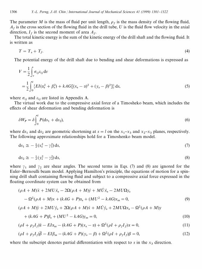
free-body diagram element of a drill shaft of length ds, and a corresponding enclosed #uidcomponent of volume d< are shown in Fig. 2.
1304 Y.-L. Perng, J.-H. Chin / International Journal of Mechanical Sciences 41 (1999) 1301}1322
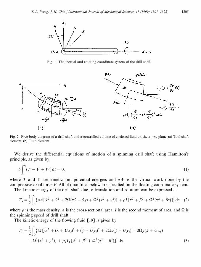
Fig. 1. The inertial and rotating coordinate system of the drill shaft.
Fig. 2. Free-body diagram of a drill shaft and a controlled volume of enclosed #uid on the x1}x
3plane: (a) Tool shaft
element; (b) Fluid element.
We derive the di!erential equations of motion of a spinning drill shaft using Hamilton'sprinciple, as given by
dPt2
t1
(¹!<#=) dt"0, (1)
where ¹ and < are kinetic and potential energies and d= is the virtual work done by thecompressive axial force P. All of quantities below are speci"ed on the #oating coordinate system.
The kinetic energy of the drill shaft due to translation and rotation can be expressed as
¹s"
12P
l
0
MoA[xR 2#yR 2#2)(xyR !xR y)#)2 (x2#y2)]#oI[aR 2#bQ 2#)2 (a2#b2)]Nds, (2)
where o is the mass density, A is the cross-sectional area, I is the second moment of area, and ) isthe spinning speed of drill shaft.
The kinetic energy of the #owing #uid [19] is given by
¹f"
12P
l
0
MM[;2#(xR #;xs)2#(yR #;y
s)2#2)x(yR #;y
s)!2)y(xR #;x
s)
#)2(x2#y2 )]#ofIf[aR 2#bQ 2#)2(a2#b2)]Nds. (3)
Y.-L. Perng, J.-H. Chin / International Journal of Mechanical Sciences 41 (1999) 1301}1322 1305
The parameter M is the mass of #uid per unit length, of
is the mass density of the #owing #uid,A
fis the cross section of the #owing #uid in the drill tube, ; is the #uid #ow velocity in the axial
direction, If
is the second moment of area Af.
The total kinetic energy is the sum of the kinetic energy of the drill shaft and the #owing #uid. Itis written as
¹"¹s#¹
f. (4)
The potential energy of the drill shaft due to bending and shear deformations is expressed as
<"12P
v
pijeijdv
"
12 P
l
0
MEI(a2s#b2
s)#kAG[(x
s!a)2#(y
s!b)2]Nds, (5)
where pij
and eij
are listed in Appendix A.The virtual work due to the compressive axial force of a Timosheko beam, which includes the
e!ects of shear deformation and bending deformation is
d=P"dP
l
0
P(ds1#ds
2), (6)
where ds1
and ds2
are geometric shortening at s"l on the x1}x
3and x
2}x
3planes, respectively.
The following approximate relationships hold for a Timoshenko beam model.
ds1:!1
2(x2
s!c2
1) ds, (7)
ds2:!1
2(y2
s!c2
2) ds, (8)
where c1
and c2
are shear angles. The second terms in Eqs. (7) and (8) are ignored for theEuler}Bernoulli beam model. Applying Hamilton's principle, the equations of motion for a spin-ning drill shaft containing #owing #uid and subject to a compressive axial force expressed in the#oating coordinate system can be obtained from
(oA#M)xK#2M;xRs!2)(oA#M)yR #M;Q xR
s!2M;)y
s
!)2(oA#M)x#(kAG#P)as#(M;2!kAG)x
ss"0, (9)
(oA#M)yK#2M;yRs#2)(oA#M)xR #M;Q yR
s#2M;)x
s!)2(oA#M)y
#(kAG#P)bs#(M;2!kAG)y
ss"0, (10)
(oI#ofIf)aK!EIa
ss!(kAG#P)(x
s!a)#)2(oI#o
fIf)a"0, (11)
(oI#ofIf)bG!EIb
ss!(kAG#P) (y
s!b)#)2(oI#o
fIf)b"0, (12)
where the subscript denotes partial di!erentiation with respect to s in the x3
direction.
1306 Y.-L. Perng, J.-H. Chin / International Journal of Mechanical Sciences 41 (1999) 1301}1322
If #uid #ow M is ignored for a non-spinning drill shaft with two degrees of freedom in Eqs.(9)}(12), they are the same as the equations in [13, 15]. If #uid #ow M and compressive axial forceP are both ignored in Eqs. (9)}(12), they are the same as the homogeneous equations in [21]. Eqs.(9)}(12) are coupled partial di!erential equations. For convenience, the complex rotation andde#ection are used to Eqs. (9)}(12). Let
tI "a#ib, (13)
uJ "x#iy, (14)
i"J!1. (15)
Substituting tI and uJ into Eqs. (9)} (12), we obtain the complex-form Equations of motion asfollows:
(oA#M)uJ G#2M;uJQs#i2)(oA#M)uJ Q #M;Q uJ
s#i2M;)uJ
s
!)2(oA#M)uJ #(kAG#P)tIs#(M;2!kAG)uJ
ss"0, (16)
(oI#ofIf)tI G!EItI
ss!(kAG#P)(uJ
s!tI )#)2(oI#o
fIf)tI "0. (17)
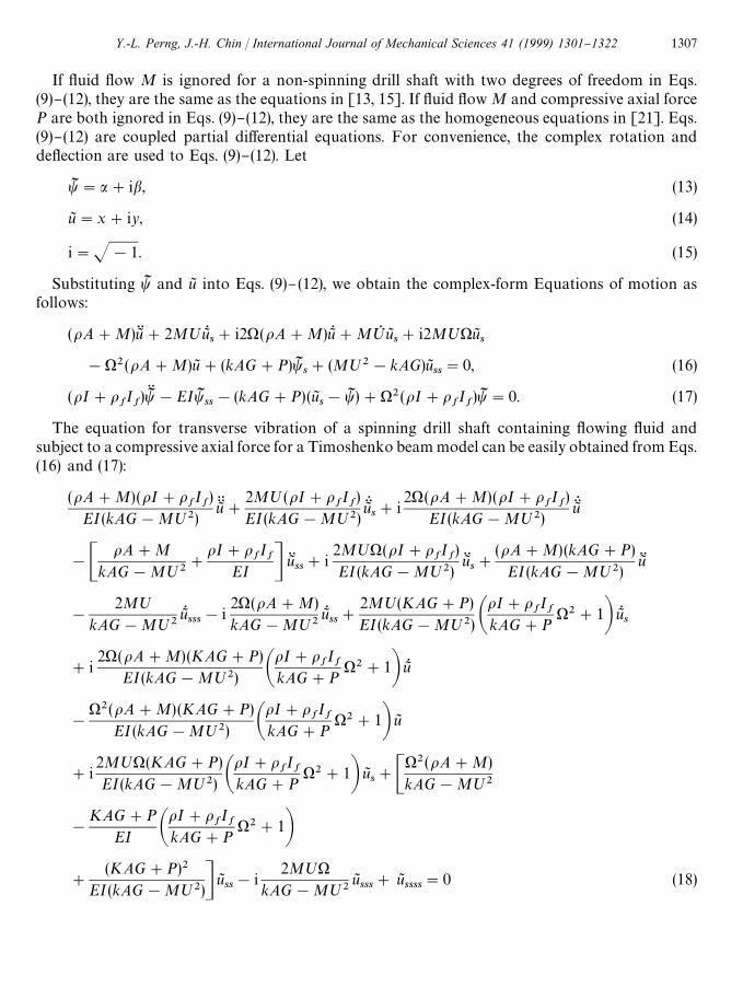
The equation for transverse vibration of a spinning drill shaft containing #owing #uid andsubject to a compressive axial force for a Timoshenko beam model can be easily obtained from Eqs.(16) and (17):
(oA#M)(oI#ofIf)
EI(kAG!M;2)uJ GG#
2M;(oI#ofIf)
EI(kAG!M;2)uJ GQs#i
2) (oA#M)(oI#ofIf)
EI(kAG!M;2)uJ GQ
!CoA#M
kAG!M;2#
oI#ofIf
EI D uJ Gss#i
2M;)(oI#ofIf)
EI(kAG!M;2)uJ Gs#
(oA#M) (kAG#P)EI(kAG!M;2)
uJ G
!
2M;kAG!M;2
uJQsss!i
2)(oA#M)kAG!M;2
uJQss#
2M;(KAG#P)EI(kAG!M;2) A
oI#ofIf
kAG#P)2#1B uJQ
s
#i2)(oA#M)(KAG#P)
EI(kAG!M;2) AoI#o
fIf
kAG#P)2#1B uJQ
!
)2(oA#M) (KAG#P)EI (kAG!M;2) A
oI#ofIf
kAG#P)2#1B uJ
#i2M;)(KAG#P)EI(kAG!M;2) A
oI#ofIf
kAG#P)2#1B uJ
s#C
)2(oA#M)kAG!M;2
!
KAG#PEI A
oI#ofIf
kAG#P)2#1B
#
(KAG#P)2EI(kAG!M;2)D uJ
ss!i
2M;)kAG!M;2
uJsss#uJ
ssss"0 (18)
Y.-L. Perng, J.-H. Chin / International Journal of Mechanical Sciences 41 (1999) 1301}1322 1307

If #uid #ow M is ignored for a non-spinning drill shaft in Eq. (18), it is the same as the equation in[13]. Fluid #ow M and compressive axial force P can be ignored for a non-spinning drill shaft inEq. (18). Eq. (18) then becomes the same as the equation in [7].
Eq. (18) can be rendered dimensionless by using the following dimensionless parameters:
g"uJl, f"
sl, tM"
tl C
EI (kAG!M;2)(oA#M) (oI#o
fIf)D
1@4
)1 "l)C(oI#o
fIf)3(kAG!M;2)
(EI)3 (oA#M) D1@4
,
;M ";CEI(oA#M)3
(oI#ofIf) (kAG!M;2)3D
1@4,
MM "CEI(oA#M)
(kAG!M;2)(oI#ofIf)D
1@2, (19)
mN "M
oA#M, PM "
M;2#PkAG!M;2
,
KM "kAG#P
EIl2, RM "
kAG#PkAG!M;2
,
which takes the following form:
gKK#2m6 ;1M1
gGQ f#i2MM )1 gKK!AM1 #1M1 BgK ff#i2m6 ;M )1 gK f#M1 K1 gK!2m6 ;1 gR fff
!i2)1 M1 2gR ff#2m6 ;1 (K1 #M1 )1 2)gR f#i2(K1 M1 2)1 #M1 3)1 3)gR
!(K1 M1 3)1 2#M1 4)1 4)g#i2(m6 ;1 K1 M1 )1 #m6 ;1 M1 2)1 3)gf#(M1 3)1 2!M1 )1 2!K1 #K1 R1 )gff!i2m6 ;1 M1 )1 gfff#gffff"0. (20)
The equations of motion based on the Euler}Bernoulli beam theory for a spinning drill shaftwith #owing #uid and subject to a compressive axial force can be obtained in a similar way. InEuler}Bernoulli beam theory, the e!ects of shear deformation, gyroscopic moment, and moment ofcross-sectional rotatory inertia are ignored. Therefore, we obtain the following equation:
oA#MEI
uJ G#i2) (oA#M)
EIuJQ !
)2(oA#M)EI
u8
#
2M;EI
uJQs#i
2M;)EI
uJs#
M;2#PEI
uJss#uJ
ssss"0. (21)
If the #uid #ow M and compressive axial force P are ignored for a non-spinning drill shaft in Eq.(21), it is the same as the equations in [22, 2] where the damping e!ect is considered in [2].
1308 Y.-L. Perng, J.-H. Chin / International Journal of Mechanical Sciences 41 (1999) 1301}1322
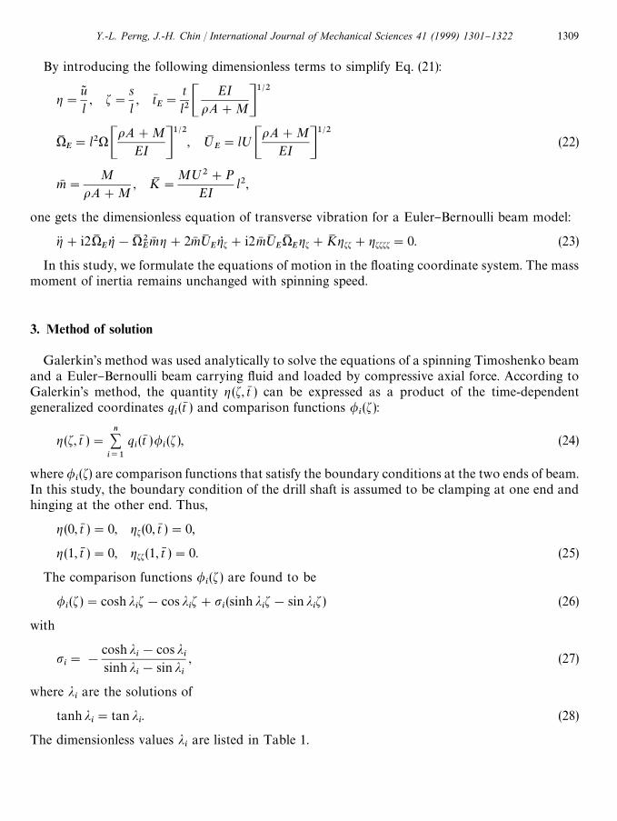
By introducing the following dimensionless terms to simplify Eq. (21):
g"u8l, f"
sl, tN
E"
tl2C
EIoA#MD
1@2
)1E"l2)C
oA#MEI D
1@2, ;M
E"l;C
oA#MEI D
1@2(22)
mN "M
oA#M, KM "
M;2#PEI
l2,
one gets the dimensionless equation of transverse vibration for a Euler}Bernoulli beam model:
gK#i2)1EgR !)1 2
Em6 g#2m6 ;1
EgR f#i2m6 ;1
E)1
Egf#K1 gff#gffff"0. (23)
In this study, we formulate the equations of motion in the #oating coordinate system. The massmoment of inertia remains unchanged with spinning speed.
3. Method of solution
Galerkin's method was used analytically to solve the equations of a spinning Timoshenko beamand a Euler}Bernoulli beam carrying #uid and loaded by compressive axial force. According toGalerkin's method, the quantity g (f, tN ) can be expressed as a product of the time-dependentgeneralized coordinates q
i(tN ) and comparison functions /
i(f):
g (f, tN )"n+i/1
qi(tN )/
i(f ), (24)
where /i(f) are comparison functions that satisfy the boundary conditions at the two ends of beam.
In this study, the boundary condition of the drill shaft is assumed to be clamping at one end andhinging at the other end. Thus,
g (0, tN )"0, gf (0, tN )"0,
g (1, tN )"0, gff(1, tN )"0. (25)
The comparison functions /i(f ) are found to be
/i(f)"cosh j
if!cos j
if#p
i(sinh j
if!sin j
if ) (26)
with
pi"!
cosh ji!cos j
isinh j
i!sin j
i
, (27)
where jiare the solutions of
tanh ji"tan j
i. (28)
The dimensionless values jiare listed in Table 1.
Y.-L. Perng, J.-H. Chin / International Journal of Mechanical Sciences 41 (1999) 1301}1322 1309

Table 1The values of j
i
ji
value of ji
ji
value of ji
j1
3.92660246 j6
19.63495408j2
7.06858275 j7
22.77654674j3
10.21017612 j8
25.91813939j4
13.35176878 j9
29.05973205j5
16.49336143 j10
32.20132470
Substituting Eq. (24) into Eq. (20), multiplying by /j(f), and integrating it from 0 to 1, due to the
orthonormal property of the comparison functions used, the resulting dimensionless equation ofmotion in matrix form for a Timoshenko beam model becomes
AM sKK#B1 sG0 #C1 sK#D1 sR #E1 s"0, (29)
where matrices AM , BM , CM , DM , and EM are de"ned as
[AM ]ij"aN
ij,
[BM ]ij"
2mN ;MMM
bNij#i2MM )1 aN
ij,
[CM ]ij"!AMM #
1MM B cN
ij#i2mN ;M )1 bN
ij#MM KM aN
ij,
[DM ]ij"!2mN ;M dM
ij!i2)1 MM 2cN
ij#2mN ;M (KM #MM )1 2)bN
ij#i2()1 3MM 3#KM )1 MM 2)aN
ij,
[EM ]ij"eN
ij!i2mN ;M )1 MM dM
ij#()1 2MM 3!)1 2MM !KM #KM RM )cN
ij
#i2(KM mN ;M MM )1 #)1 3mN ;M MM 2)bNij!()1 4MM 4#KM )1 2MM 3)aN
ij
and
aNij"P
1
0
/i(f)/
j(f) df"G
0, iOj,
1, i"j,
bNij"P
1
0
/i(f)/
j,f(f) df"
igjgk
4j2ij2j
j4j!j4
i
[(!1)i`j!1], iOj,
0, i"j,
cNij"P
1
0
/i(f)/
j,ff(f) df"
igjgk
4j2ij2j
j4j!j4
i
(jjpj!j
ipi) [(!1)i`j#1], iOj,
0, i"j,
1310 Y.-L. Perng, J.-H. Chin / International Journal of Mechanical Sciences 41 (1999) 1301}1322
dMij"P
1
0
/i(f)/
j,fff(f) df"
igjgk
4j2ij2j
j4j!j4
i
[pipj!(!1)i`j], iOj,
0, i"j,
eNij"P
1
0
/i(f)/
j,ffff(f) df"G0, iOj,
j4i, i"j,
where the operator ( )j,f in the expressions above denotes di!erentiation with respect to the f of jth
comparison function. In order to obtain a set of 4n "rst-order di!erentiation equations, we cande"ne the state vector as
Z"GsssKsKQ H , ZQ "G
sRsKsG0
sKK H . (30)
Substituting Eq. (30) into Eq. (29) yields
GsRsKsK0sKK H"
01 IM 01 01
01 01 IM 01
01 01 01 IM!AM ~1EM !AM ~1DM !AM ~1CM !AM ~1BM G
ssRsKsG0 H$ (31)
Or Eq. (31) can be compactly rewritten in matrix form
ZQ "HZ. (32)
In Eq. (31), 01 is zero matrix and IM is the identity matrix of size n]n. It is an eigenvalue problemand k represents the eigenvalues of matrix H. For non-trivial solutions, the characteristic equationis
det DH!kI1 D"0. (33)
The values of k are complex eigenvalues that comprise real parts of q's and imaginary parts ofu's, i.e., k"q#iu. Note that the imaginary parts of u's are transverse natural frequencies of thedrill shaft.
The solution for the Euler}Bernoulli beam model of a spinning drill shaft containing #owing#uid and loaded by a compressive axial force can be easily found in a similar way.
4. Simulation results
The theoretical equations of motion based on the #oating coordinate system derived in thepreceding section were numerically simulated using MATLAB software. Drill shaft parameters and
Y.-L. Perng, J.-H. Chin / International Journal of Mechanical Sciences 41 (1999) 1301}1322 1311

Fig. 3. Variations in natural frequency with spinning speed; without static #uid, P"0 kg (F: forward precession B:backward precession).
material properties for these numerical simulations are listed in Appendix B. In the computerprogram, the assumed mode number n in Section 3 was set to 40 for convergence using Galerkin'smethod. The Timoshenko beam and Euler}Bernoulli beam models formulated in Eqs. (20) and (23)were studied under various drilling conditions such as di!erent spinning speeds ()), compressiveaxial forces (P), and #uid #ow velocities (;). The complex eigenvalues of the dynamic system werecalculated using the characteristic Eq. (33). The transverse natural frequencies of the drill shaft weredetermined from the imaginary parts of the complex eigenvalues k. The theoretical results for theTimoshenko beam and Euler}Bernoulli beam models were compared with each other.
The following dimensionless parameters were de"ned for the sake of clear representation: (a)uN "u
n/u
10, nth-mode non-dimensional natural frequency parameter; (b) I1 ")/u
10, non-dimen-
sional spinning speed parameter; (c) !1 ";/;cr, non-dimensional #uid #ow velocity parameter
along the axial direction; (d) R1 "P/Pcr, non-dimensional compressive axial force parameter. u
10is
natural frequency of the "rst mode of a non-spinning drill shaft without #uid. ;cr
is the maximumvalue in the range of #uid #ow velocities that we were interested in. Here, we set;
crto 32 m/s from
Chang [23, 24]. Pcr
is the Euler critical buckling load given by n2EI/l2.Variations in natural frequencies corresponding to the "rst four mode-shapes of drill shaft at the
dimensionless spinning speed parameter I1 are sketched in Figs. 3 and 4 for the clamped-hingedTimoshenko beam model described in Eq. (20). It can be seen that the static cutting #uid containedin BTA deep-hole drill tube decrease the transverse natural frequencies, and also that a naturalfrequency bifurcation occurred. There were four natural frequencies in each mode for theTimoshenko beam model. One pair of natural frequencies occurred at lower-orders of magnitude,the other at higher-orders of magnitude. Since the pair of natural frequencies occurring at higherorders of magnitude were of little signi"cance, we considered only the pair of natural frequenciesoccurring at lower orders. There was only one pair of natural frequencies at lower-orders ofmagnitude for the Euler}Bernoulli beam model. It should be noted that if spinning ceases, only one
1312 Y.-L. Perng, J.-H. Chin / International Journal of Mechanical Sciences 41 (1999) 1301}1322
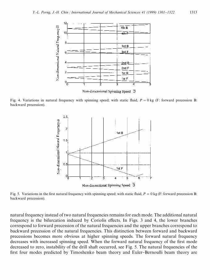
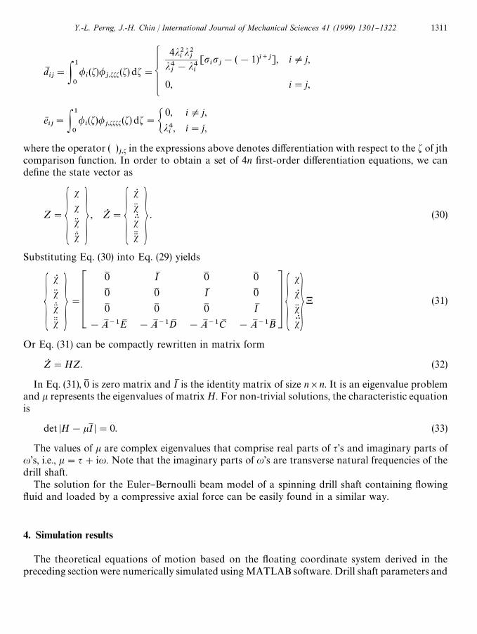
Fig. 4. Variations in natural frequency with spinning speed; with static #uid, P"0 kg (F: forward precession B:backward precession).
Fig. 5. Variations in the "rst natural frequency with spinning speed; with static #uid, P"0 kg (F: forward precession B:backward precession).
natural frequency instead of two natural frequencies remains for each mode. The additional naturalfrequency is the bifurcation induced by Coriolis e!ects. In Figs. 3 and 4, the lower branchescorrespond to forward precession of the natural frequencies and the upper branches correspond tobackward precession of the natural frequencies. This distinction between forward and backwardprecessions becomes more obvious at higher spinning speeds. The forward natural frequencydecreases with increased spinning speed. When the forward natural frequency of the "rst modedecreased to zero, instability of the drill shaft occurred, see Fig. 5. The natural frequencies of the"rst four modes predicted by Timoshenko beam theory and Euler}Bernoulli beam theory are
Y.-L. Perng, J.-H. Chin / International Journal of Mechanical Sciences 41 (1999) 1301}1322 1313

Fig. 7. Variations in the "rst natural frequency with velocity of #owing #uid; P"0 kg, )"0 rpm, (F: forward precessionB: backward precession).
Fig. 6. Variations in natural frequency with spinning speed; with static #uid, P"0 kg (F: forward precession B:backward precession) (}) Timoshenko beam, (]) Euler}Bernoulli beam).
plotted in Fig. 6. It can be seen that the two generated very close results for smaller drillingdiameters. Slight di!erences occurred the lower modes at higher spinning speeds, but the di!erencein natural frequency between the two models became larger for the ¹-Max (drilling diametergreater than 65 mm) type deep-hole drill shaft.
The in#uence of #uid #ow velocity on the "rst natural frequency, with no spinning speed andcompressive axial force, is shown in Fig. 7. It can be observed that the natural frequencies dependheavily on #uid #ow velocity. Fluid #ow velocity tends to lower the transverse natural frequencies
1314 Y.-L. Perng, J.-H. Chin / International Journal of Mechanical Sciences 41 (1999) 1301}1322

Fig. 8. Variations in the "rst natural frequency with compressive axial force; with static #uid, )"0 rpm, (F: forwardprecession B: backward precession).
Table 2The natural frequencies of modes 1}4 of transverse vibration of a BTA drill shaft; without#uid; spinning speed )"0 rpm (unit: Hz)
Mode 0 kg 20 kg 40 kg 60 kg 80 kg 100 kg
u1
30.809 30.490 30.168 29.842 29.512 29.177u
299.743 99.279 98.813 98.345 97.874 97.400
u3
207.759 207.239 206.717 206.195 205.670 205.144u
4354.452 353.901 353.350 352.797 352.243 351.689
of spinning drill shafts, especially, for the "rst natural mode, at which the e!ect of #uid #ow velocitywill result in instability in BTA deep-hole drilling as the critical #ow velocity;
cis approached, i.e.,
the forward precession of natural frequencies decreases to zero.The in#uence of compressive axial loads on the "rst natural frequency of a drill shaft with static#uid is plotted in Fig. 8. Variations in the "rst}fourth natural frequencies under compressive axialloading are listed in Tables 2}4. Compressive axial force applied to drill shafts tends to lowernatural frequencies because the compressive axial forces soften the e!ective shaft sti!nesses. Bycontrast, the tensile force strengthens the e!ective shaft sti!ness for higher-order vibration mode,decreasing the importance of this e!ect. Thus, we were concerned with lower-order vibrationmodes. In particular, the critical axial loading N
Cresults in instability as forward precession of the
"rst natural frequency decreases to zero. This e!ect is similar to that of spinning speeds and #uid#ow velocities in BTA deep-hole drill shaft. Results for both models for the "rst to fourth averagenatural frequencies of the drill shafts with and without static #uid, and spinning speed at 300 rpm
Y.-L. Perng, J.-H. Chin / International Journal of Mechanical Sciences 41 (1999) 1301}1322 1315

Table 3The natural frequencies of modes 1}4 of transverse vibration of a BTA drill shaft; with static #uid;compressive axial force P"0 kg (unit: Hz)
Spinning speeds
Mode 0 rpm 75 rpm 300 rpm 450 rpm 675 rpm 1050 rpm 1425 rpm
u1
31.250 30.950 30.500 30.250 30.000 29.300 29.000u
298.750 95.250 95.000 95.000 95.000 93.750 93.750
u3
202.750 191.500 190.000 190.000 190.000 189.000 190.000u
4325.000 307.500 311.250 307.500 306.250 305.000 303.750
Table 4The natural frequencies of modes 1}4 of transverse vibration of a BTA drill shaft; without#uid; compressive axial force P"0 kg (unit: Hz)
Spinning speeds
Mode 0 rpm 300 rpm 525 rpm 750 rpm 1050 rpm 1425 rpm
u1
32.450 31.577 31.250 31.250 31.250 31.250u
2102.500 97.745 97.500 97.500 96.250 93.750
u3
208.496 206.386 205.625 205.000 205.000 203.750u
4345.514 333.372 332.500 332.500 332.500 331.250
Table 5The natural frequencies of modes 1}4 of transverse vibrationof a BTA drill shaft; with static #uid; compressive axial forceP"0 kg; spinning speed )"300 rpm (unit: Hz)
Mode Experiment Timoshenko Euler
u1
30.500 29.470 29.477u
295.000 95.408 95.526
u3
190.000 198.734 199.307u
4311.250 339.062 340.827
under zero compressive axial force are listed in Tables 5 and 6. Agreement was obtained for smallerdrill shaft in this study. But for ¹-Max (above 65 mm) type deep-hole drill shafts, the e!ects of sheardeformation, rotatory inertia moment, and gyroscopic moment could not be ignored. The di!er-ence in natural frequency between the two models was about 10% for 75 mm diameter drill shaftsin numerical simulations.
1316 Y.-L. Perng, J.-H. Chin / International Journal of Mechanical Sciences 41 (1999) 1301}1322
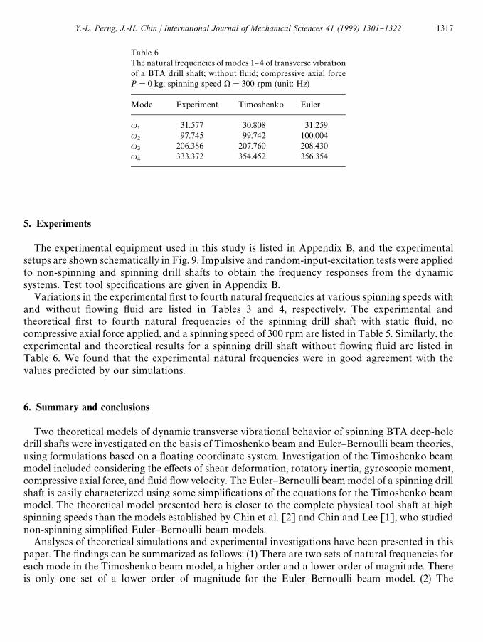
Table 6The natural frequencies of modes 1}4 of transverse vibrationof a BTA drill shaft; without #uid; compressive axial forceP"0 kg; spinning speed )"300 rpm (unit: Hz)
Mode Experiment Timoshenko Euler
u1
31.577 30.808 31.259u
297.745 99.742 100.004
u3
206.386 207.760 208.430u
4333.372 354.452 356.354
5. Experiments
The experimental equipment used in this study is listed in Appendix B, and the experimentalsetups are shown schematically in Fig. 9. Impulsive and random-input-excitation tests were appliedto non-spinning and spinning drill shafts to obtain the frequency responses from the dynamicsystems. Test tool speci"cations are given in Appendix B.
Variations in the experimental "rst to fourth natural frequencies at various spinning speeds withand without #owing #uid are listed in Tables 3 and 4, respectively. The experimental andtheoretical "rst to fourth natural frequencies of the spinning drill shaft with static #uid, nocompressive axial force applied, and a spinning speed of 300 rpm are listed in Table 5. Similarly, theexperimental and theoretical results for a spinning drill shaft without #owing #uid are listed inTable 6. We found that the experimental natural frequencies were in good agreement with thevalues predicted by our simulations.
6. Summary and conclusions
Two theoretical models of dynamic transverse vibrational behavior of spinning BTA deep-holedrill shafts were investigated on the basis of Timoshenko beam and Euler}Bernoulli beam theories,using formulations based on a #oating coordinate system. Investigation of the Timoshenko beammodel included considering the e!ects of shear deformation, rotatory inertia, gyroscopic moment,compressive axial force, and #uid #ow velocity. The Euler}Bernoulli beam model of a spinning drillshaft is easily characterized using some simpli"cations of the equations for the Timoshenko beammodel. The theoretical model presented here is closer to the complete physical tool shaft at highspinning speeds than the models established by Chin et al. [2] and Chin and Lee [1], who studiednon-spinning simpli"ed Euler}Bernoulli beam models.
Analyses of theoretical simulations and experimental investigations have been presented in thispaper. The "ndings can be summarized as follows: (1) There are two sets of natural frequencies foreach mode in the Timoshenko beam model, a higher order and a lower order of magnitude. Thereis only one set of a lower order of magnitude for the Euler}Bernoulli beam model. (2) The
Y.-L. Perng, J.-H. Chin / International Journal of Mechanical Sciences 41 (1999) 1301}1322 1317

Fig. 9. Experimental setup for random-input testing.
Timoshenko beam and Euler}Bernoulli beam model display that the natural frequencies of thedynamic system possess backward and forward precession natural frequencies which dependstrongly on spinning speeds. When spinning ceases, only one instead of two natural frequenciesremain. The additional natural frequency is a bifurcation induced by Coriolis e!ects. (3) Thedistinction between backward and forward precessions becomes more obvious at higher spinningspeeds. Since advances in bearing technology have made it possible to increase spindle speeds up to60 000 rpm in high speed drilling, the e!ects of rotatory inertia and gyroscopic moments aresigni"cant when using BTA deep-hole drills. (4) The e!ect of #uid #ow velocity tends to decreasetransverse natural frequencies of spinning drill shafts. (5) Compressive axial force applied tospinning drill shafts softens the e!ective sti!ness of the shafts, but the tensile force strengthens thee!ective sti!ness of the shafts. The transverse natural frequency of a dynamic system decreases withapplied force. (6) Theoretical simulations and experimental investigations showed good agreement.
1318 Y.-L. Perng, J.-H. Chin / International Journal of Mechanical Sciences 41 (1999) 1301}1322
Acknowledgements
The authors thank the National Science Council of the Republic of China for its support of thisstudy under Grant Number NSC-86-2212-E-009-048.
Appendix A
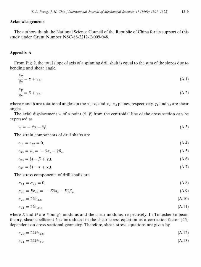
From Fig. 2, the total slope of axis of a spinning drill shaft is equal to the sum of the slopes due tobending and shear angle.
LxLs
"a#c1, (A.1)
LyLs
"b#c2, (A.2)
where a and b are rotational angles on the x1}x
3and x
2}x
3planes, respectively. c
1and c
2are shear
angles.The axial displacement w of a point (xN , yN ) from the centroidal line of the cross section can be
expressed as
w"!xN a!y6 b. (A.3)
The strain components of drill shafts are
e11
"e22"0, (A.4)
e33
"ws"!x6 a
s!y6 b
s, (A.5)
e23
"12(!b#y
s), (A.6)
e31
"12(!a#x
s). (A.7)
The stress components of drill shafts are
p11"p
22"0, (A.8)
p33"Ee
33"!Ex6 a
s!Ey6 b
s, (A.9)
p23"2Ge
23, (A.10)
p31"2Ge
31, (A.11)
where E and G are Young's modulus and the shear modulus, respectively. In Timoshenko beamtheory, shear coe$cient k is introduced in the shear}stress equation as a correction factor [25]dependent on cross-sectional geometry. Therefore, shear}stress equations are given by
p23"2kGe
23, (A.12)
p31"2kGe
31. (A.13)
Y.-L. Perng, J.-H. Chin / International Journal of Mechanical Sciences 41 (1999) 1301}1322 1319
The strain energy is
<"12P
v
pijeijdv (A.14)
Appendix B
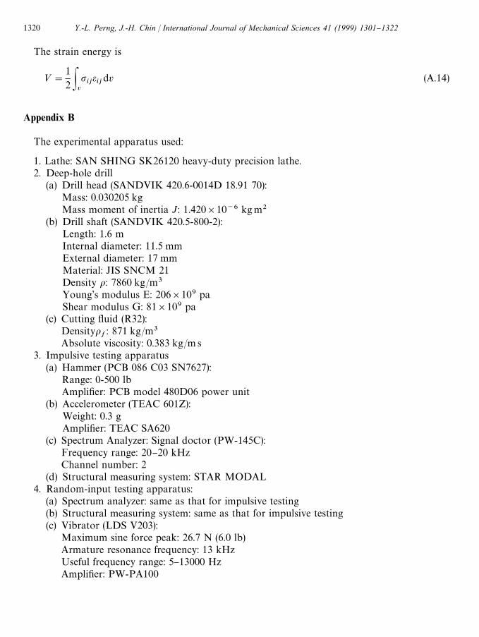
The experimental apparatus used:
1. Lathe: SAN SHING SK26120 heavy-duty precision lathe.2. Deep-hole drill
(a) Drill head (SANDVIK 420.6-0014D 18.91 70):Mass: 0.030205 kgMass moment of inertia J: 1.420]10~6 kgm2
(b) Drill shaft (SANDVIK 420.5-800-2):Length: 1.6 mInternal diameter: 11.5 mmExternal diameter: 17 mmMaterial: JIS SNCM 21Density o: 7860 kg/m3Young's modulus E: 206]109 paShear modulus G: 81]109 pa
(c) Cutting #uid (R32):Densityo
f: 871 kg/m3
Absolute viscosity: 0.383 kg/m s3. Impulsive testing apparatus
(a) Hammer (PCB 086 C03 SN7627):Range: 0-500 lbAmpli"er: PCB model 480D06 power unit
(b) Accelerometer (TEAC 601Z):Weight: 0.3 gAmpli"er: TEAC SA620
(c) Spectrum Analyzer: Signal doctor (PW-145C):Frequency range: 20}20 kHzChannel number: 2
(d) Structural measuring system: STAR MODAL4. Random-input testing apparatus:
(a) Spectrum analyzer: same as that for impulsive testing(b) Structural measuring system: same as that for impulsive testing(c) Vibrator (LDS V203):
Maximum sine force peak: 26.7 N (6.0 lb)Armature resonance frequency: 13 kHzUseful frequency range: 5}13000 HzAmpli"er: PW-PA100
1320 Y.-L. Perng, J.-H. Chin / International Journal of Mechanical Sciences 41 (1999) 1301}1322
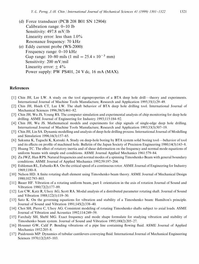
(d) Force transducer (PCB 208 B01 SN 12904):Calibration range: 0}10 lbSensitivity: 497.8 mV/lbLinearity error: less than 1.0%Resonance frequency: 70 kHz
(e) Eddy current probe (WS-2000):Frequency range: 0}10 kHzGap range: 10}80 mils (1 mil"25.4]10~3 mm)Sensitivity: 200 mV/milLinearity error:$4%Power supply: PW PS401, 24 Vdc, 16 mA (MAX).
References
[1] Chin JH, Lee LW. A study on the tool eigenproperties of a BTA deep hole drill*theory and experiments.International Journal of Machine Tools Manufacture, Research and Application 1995;35(1):29}49.
[2] Chin JH, Hsieh CT, Lee LW. The shaft behavior of BTA deep hole drilling tool. International Journal ofMechanical Sciences 1996;38(5):461}82.
[3] Chin JH, Wu JS, Young RS. The computer simulation and experimental analysis of chip monitoring for deep holedrilling. ASME Journal of Engineering for Industry 1993;115:184}92.
[4] Chin JH, Wu JS. Mathematical models and experiments for chip signals of single-edge deep hole drilling.International Journal of Machine Tools Manufacture, Research and Application 1993;33(3):507}19.
[5] Chin JH, Lin SA. Dynamic modelling and analysis of deep-hole drilling process. International Journal of Modellingand Simulation 1996;16(3):157}65.
[6] Sakuma K, Taguchi K, Katsuki A. Study on deep-hole boring by BTA system solid boring tool*behavior of tooland its e!ects on pro"le of machined hole. Bulletin of the Japan Society of Precision Engineering 1980;14(3):143}8.
[7] Huang TC. The e!ect of rotatory inertia and of shear deformation on the frequency and normal mode equations ofuniform beams with simple end conditions. ASME Journal Applied Mechanics 1961:579}84.
[8] Zu JWZ, Han RPS. Natural frequencies and normal modes of a spinning Timoshenko Beam with general boundaryconditions. ASME Journal of Applied Mechanics 1992;59:197}204.
[9] Eshleman RL, Eubanks RA. On the critical speed of a continuous rotor. ASME Journal of Engineering for Industry1969;1180}8.
[10] Nelson HD. A "nite rotating shaft element using Timoshenko beam theory. ASME Journal of Mechanical Design1980;102:793}803.
[11] Bauer HF. Vibration of a rotating uniform beam, part I: orientation in the axis of rotation Journal of Sound andVibration 1980;72(2):177}89.
[12] Lee CW, Katz R, Ulsoy AG, Scott RA. Modal analysis of a distributed parameter rotating shaft. Journal of Soundand Vibration 1988;122(1):119}30.
[13] Sato K. On the governing equations for vibration and stability of a Timoshenko beam: Hamilton's principle.Journal of Sound and Vibration 1991;145(2):338}40.
[14] Choi SH, Pierre C, Ulsoy AG. Consistent modeling of rotating Timoshenko shafts subject to axial loads. ASMEJournal of Vibration and Acoustics 1992;114:249}59.
[15] Farchaly SH, Shebl MG. Exact frequency and mode shape formulate for studying vibration and stability ofTimoshenko beam system. Journal of Sound and Vibration 1995;180(2):205}27.
[16] Housner GW, Calif P. Bending vibrations of a pipe line containing #owing #uid. ASME Journal of AppliedMechanics 1952:205}8.
[17] Paidoussis MP. Dynamics of tubular cantilevers conveying #uid. International Journal of Mechanical EngineeringSciences 1970;12(2):85}103.
Y.-L. Perng, J.-H. Chin / International Journal of Mechanical Sciences 41 (1999) 1301}1322 1321

[18] Paidoussis MP, Issid NT. Dynamic stability of pipes conveying #uid. Journal of Sound and Vibration 1974;33(3):267}94.
[19] Weaver DS, Unny TE. On the dynamic stability of #uid-conveying pipes. ASME Journal of Applied Mechanics1973:48}52.
[20] Blevins RD. Flow-induced vibration, Chap. 10, New York: Krieger Publication, 1986.[21] Han RPS, Zu JWZ. Modal analysis of rotating shafts: a body-"xed axis formulation approach. Journal of Sound
and Vibration 1992;156(1):1}16.[22] Katz R, Lee CW, Ulsoy AG, Scott RA. The dynamic response of a rotating shaft subject to a moving load. Journal
of Sound and Vibration 1988;122(1):131}48.[23] Chang SG. An investigation into torsional behavior of BTA deep hole drill shaft and the e!ects of #uid speed.
Master thesis, National Chiao Tung University, Taiwan, ROC 1995, 59}61.[24] Catalog. Rotating Tools, C-1100:4-ENG SANDVIK Coromant, 1995.[25] Cowper GR. The shear coe$cient in Timoshenko's beam theory. ASME Journal of Applied Mechanics 1966:335}40.
1322 Y.-L. Perng, J.-H. Chin / International Journal of Mechanical Sciences 41 (1999) 1301}1322