Theme 8.2 Remedial Measures: Design · From Hoek and Bray. 1987. Rock Slope Engineering. Institute...
39
Mainstreaming Slope Stability Management – Hazard and Risk Assessment – to Laos Practitioners Theme 8.2 Remedial Measures: Design 8.2 – Rock Slope Stability Assessment
Transcript of Theme 8.2 Remedial Measures: Design · From Hoek and Bray. 1987. Rock Slope Engineering. Institute...
Mainstreaming Slope Stability Management –
Hazard andRisk Assessment –
to Laos Practitioners
Theme 8.2
Remedial Measures: Design
8.2 –
Rock Slope Stability Assessment
Rock Slope Stability –
Why Bother?
Steeper Slopes = Less Excavation Cost
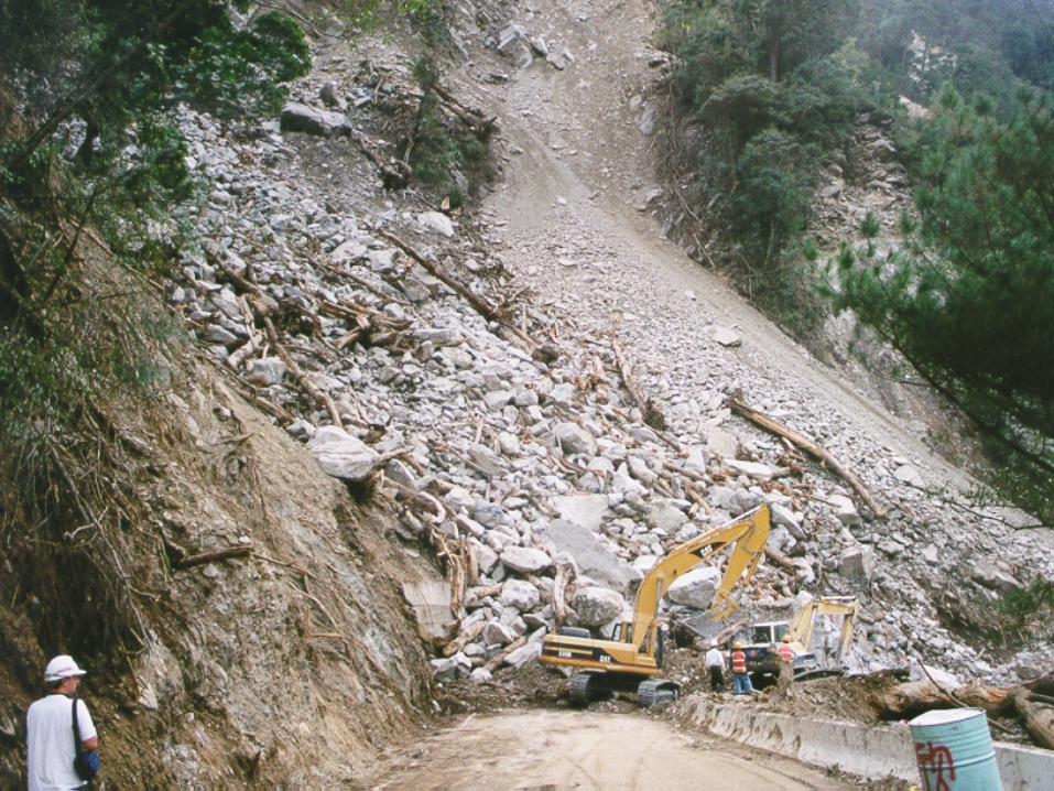
Rock slope failures on a road can result in:
Possible injury or loss of life Additional cost of removing materialDisruption to traffic / communicationExpensive remedial works
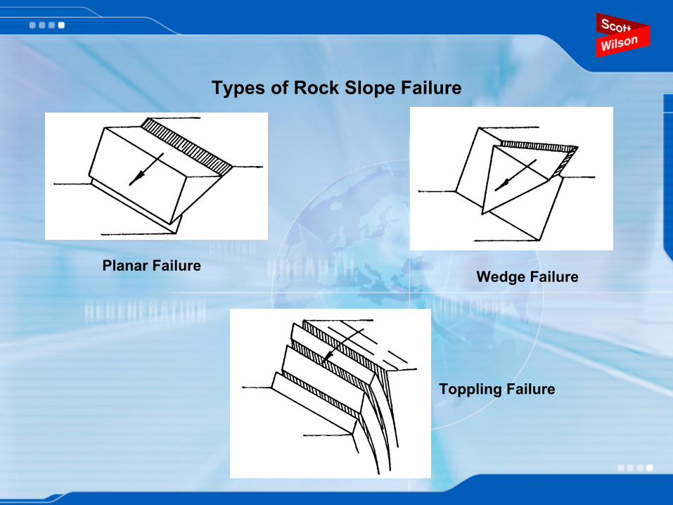
Types of Rock Slope Failure
Planar FailureWedge Failure
Toppling Failure
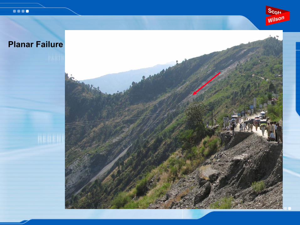
Planar Failure
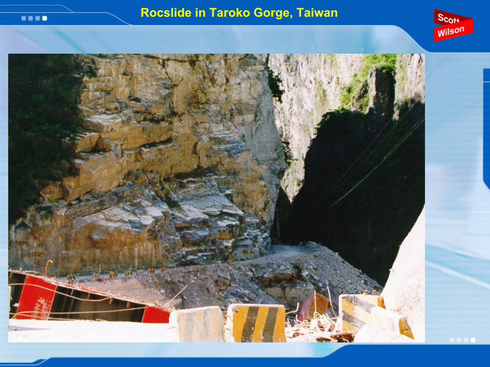
Rocslide
in Taroko
Gorge, Taiwan
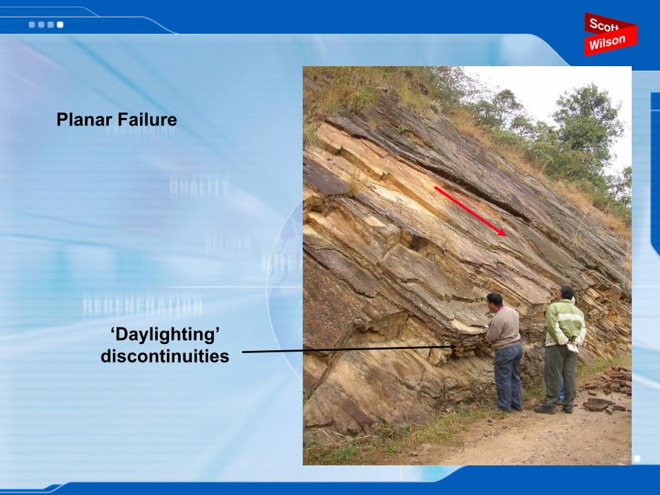
‘Daylighting’
discontinuities
Planar Failure
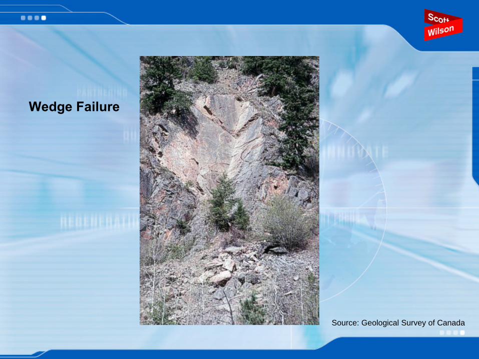
Source: Geological Survey of Canada
Wedge Failure
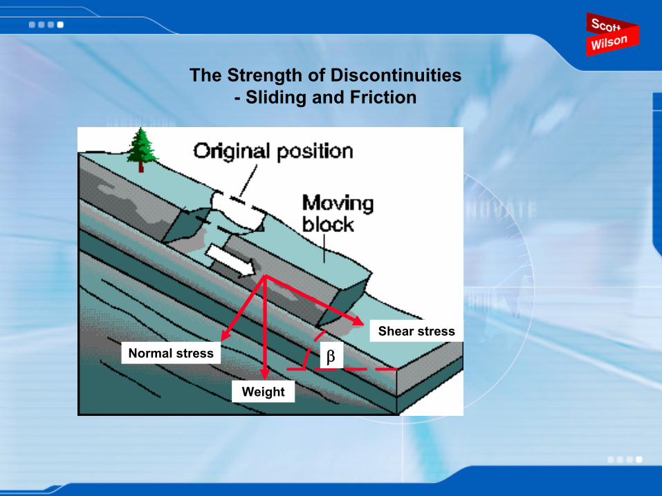
The Strength of Discontinuities
-
Sliding and Friction
Weight
Normal stressShear stress
β
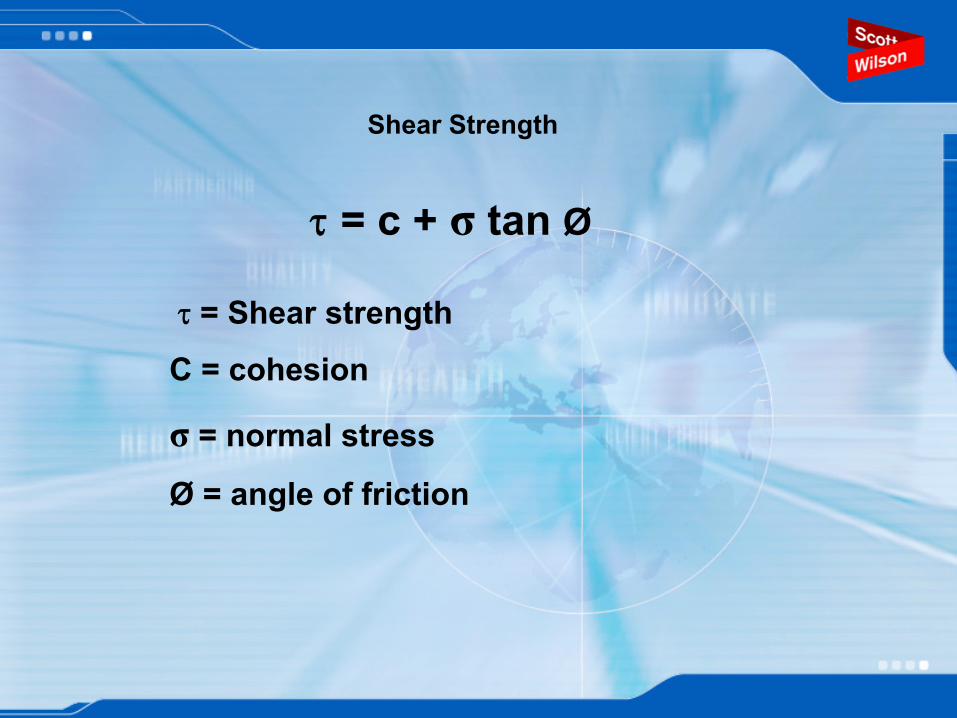
Shear Strength
τ
= c + σ
tan Ø
τ
= Shear strengthC = cohesion
σ
= normal stress
Ø
= angle of friction
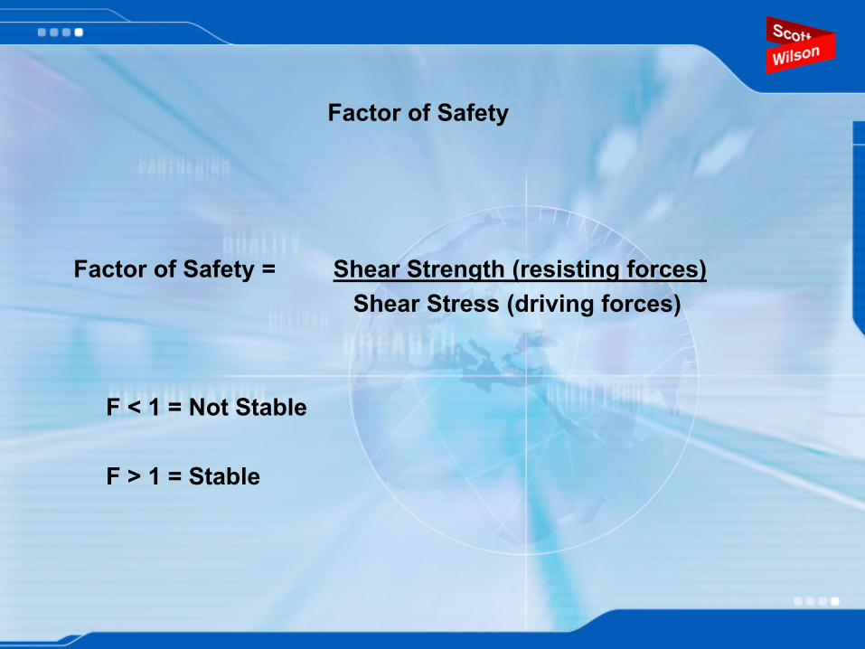
Factor of Safety
Factor of Safety = Shear Strength (resisting forces)Shear Stress (driving forces)
F < 1 = Not Stable
F > 1 = Stable
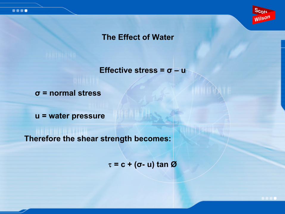
The Effect of Water
Effective stress = σ
– u
σ
= normal stress
u = water pressure
Therefore the shear strength becomes:
τ
= c + (σ- u) tan Ø

Strength of discontinuities
Direct observation of rock joints
pull testingrock shear box - portable field versions availabletilt testschmidt hammer testing
Barton’s 1976 shear strength criterion for discontinuities:
Strength of discontinuities
Barton’s model and geology:σn – a function of material density, sorting and packing – all geological controls.Base coefficient of friction (the frictional strength of a joint when all the asperities have been sheared off) is a function of the geological characteristics of the rock especially grain size.Joint roughness coefficient (JRC) is a function of the fracture origin, grain size and degree of weathering of the discontinuity.

Joint Compressive strength -
a material property
JCS is normally measured using:
Schmidt Hammer Rebound Testor
Point Load Index Test
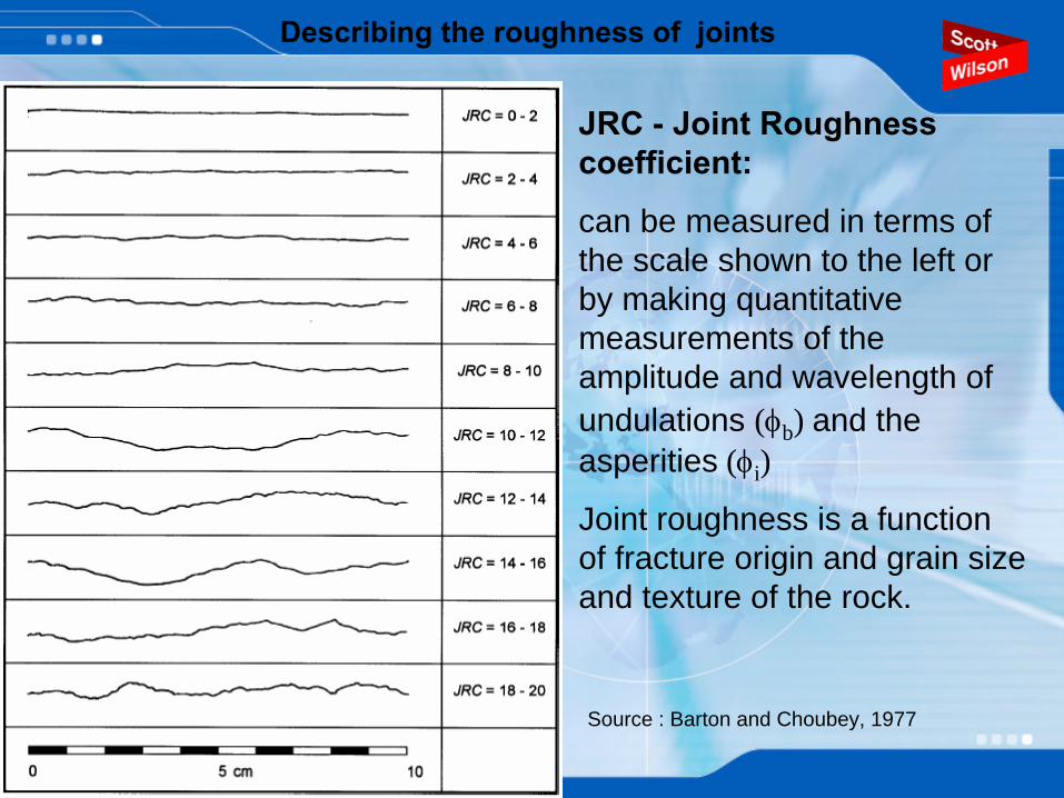
Describing the roughness of joints
JRC -
Joint Roughness coefficient:
can be measured in terms of the scale shown to the left or by making quantitative measurements of the amplitude and wavelength of undulations (φb ) and the asperities (φi )
Joint roughness is a function of fracture origin and grain size and texture of the rock.
Source : Barton and Choubey, 1977
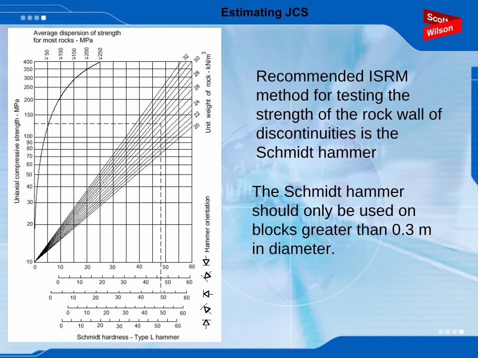
Estimating JCS
Recommended ISRM method for testing the strength of the rock wall of discontinuities is the Schmidt hammer
The Schmidt hammer should only be used on blocks greater than 0.3 m in diameter.
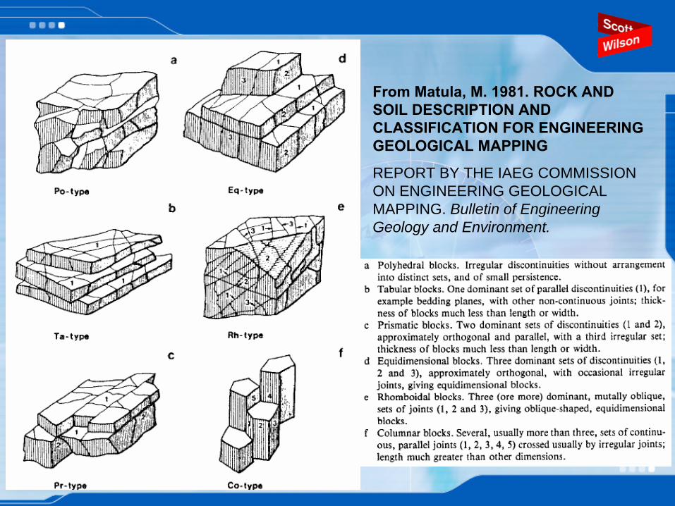
From Matula, M. 1981. ROCK AND SOIL DESCRIPTION AND CLASSIFICATION FOR ENGINEERING GEOLOGICAL MAPPING
REPORT BY THE IAEG COMMISSION ON ENGINEERING GEOLOGICAL MAPPING. Bulletin of Engineering Geology and Environment.
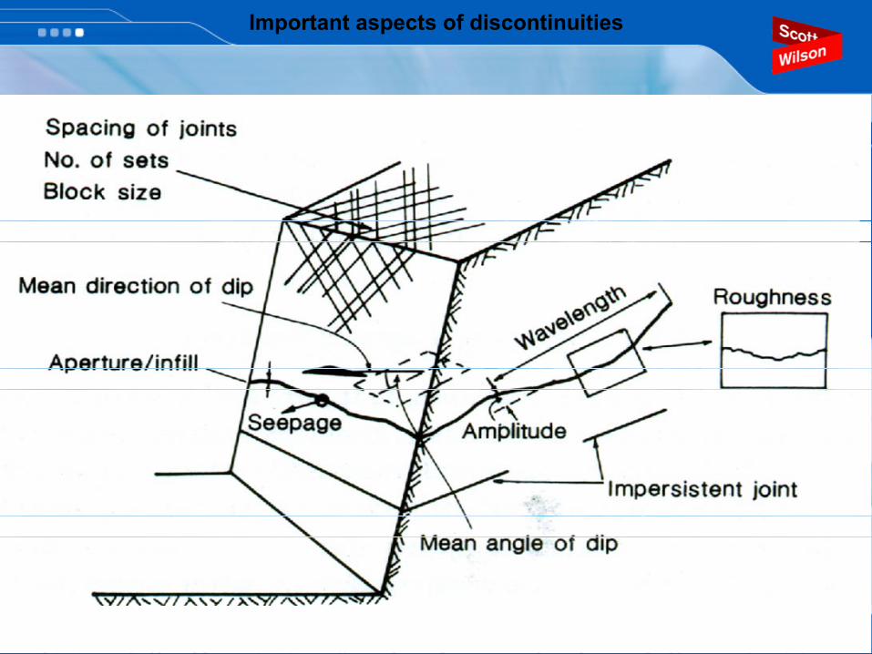
Important aspects of discontinuities
Important aspects of discontinuitiesImportant aspects of discontinuities
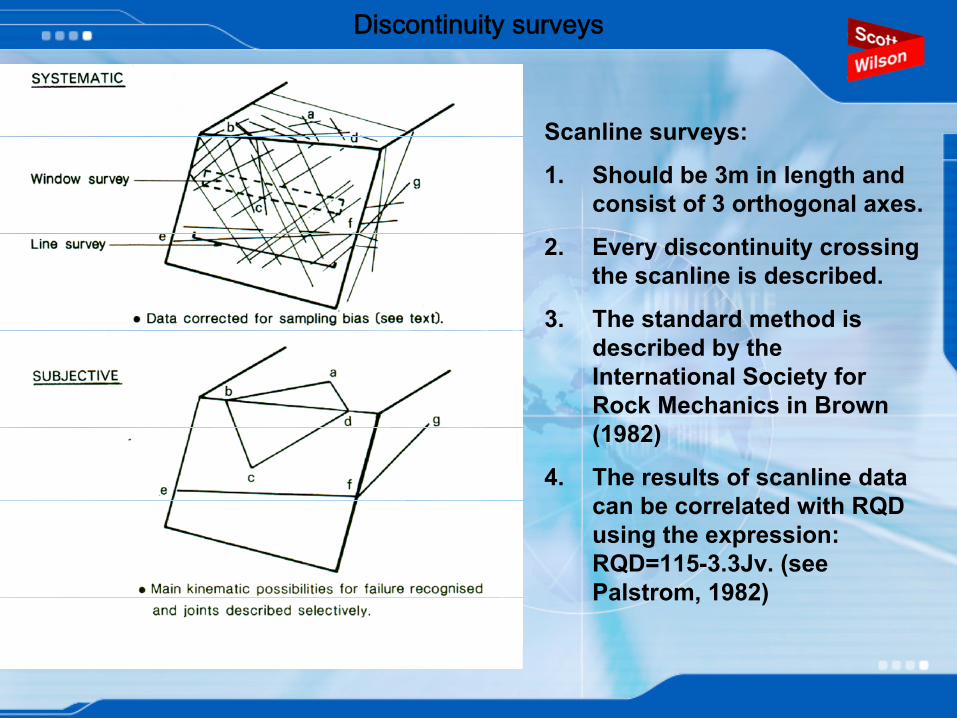
Discontinuity surveys
k
Scanline surveys:
1.
Should be 3m in length and consist of 3 orthogonal axes.
2.
Every discontinuity crossing the scanline
is described.
3.
The standard method is described by the International Society for Rock Mechanics in Brown (1982)
4.
The results of scanline
data can be correlated with RQD using the expression: RQD=115-3.3Jv. (see Palstrom, 1982)
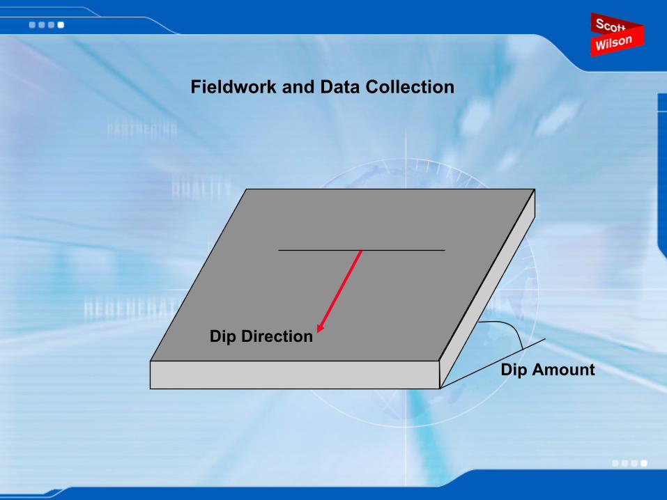
Fieldwork and Data Collection
Dip Direction
Dip Amount
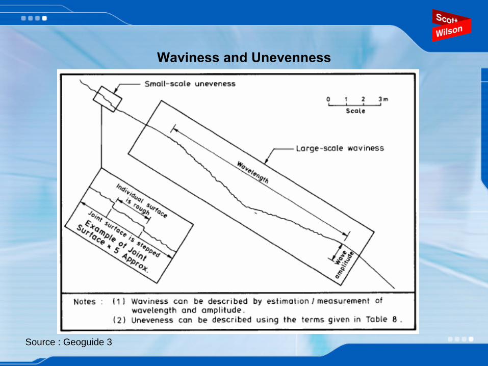
Waviness and Unevenness
Source : Geoguide 3
Discontinuity Features
Type
Persistence
Aperture
Infilling (type and consistency)
Unevenness
Waviness
Seepage/Water

Scan Line Survey Form
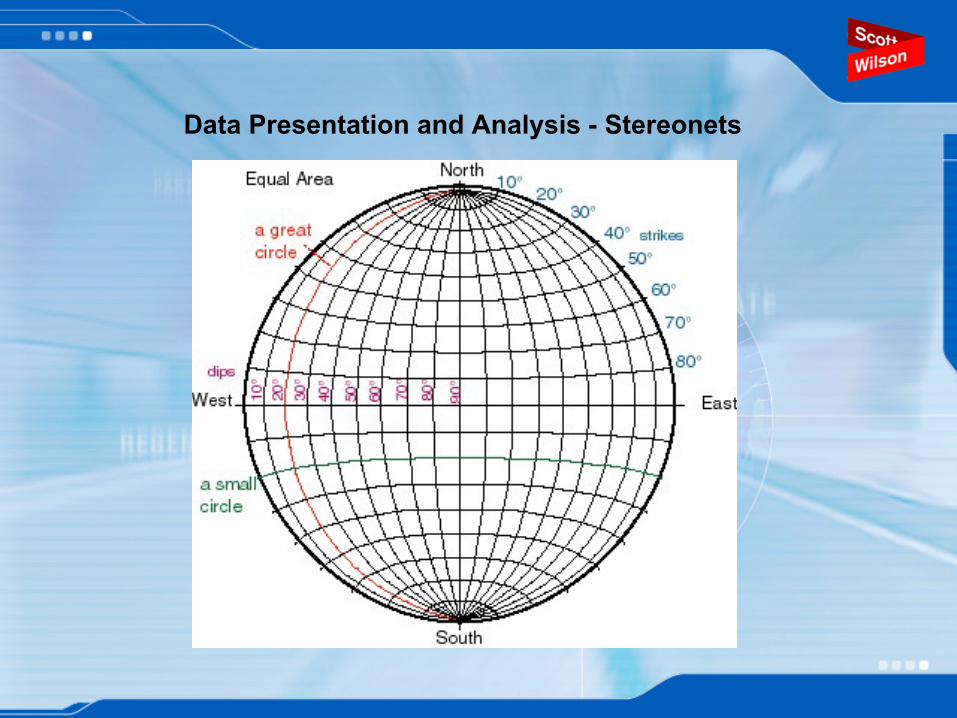
Data Presentation and Analysis -
Stereonets
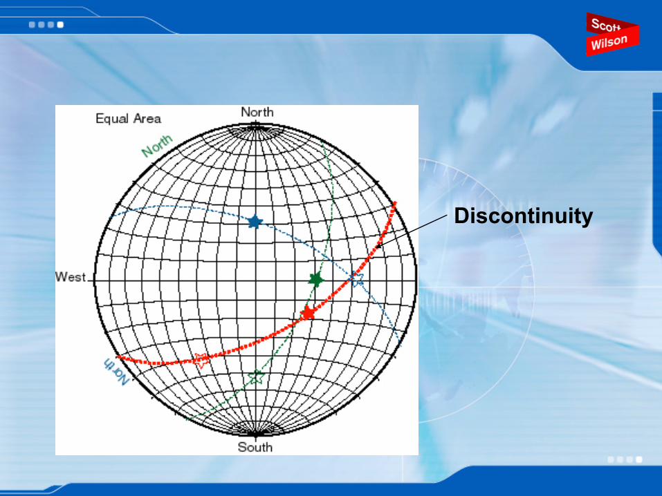
Discontinuity
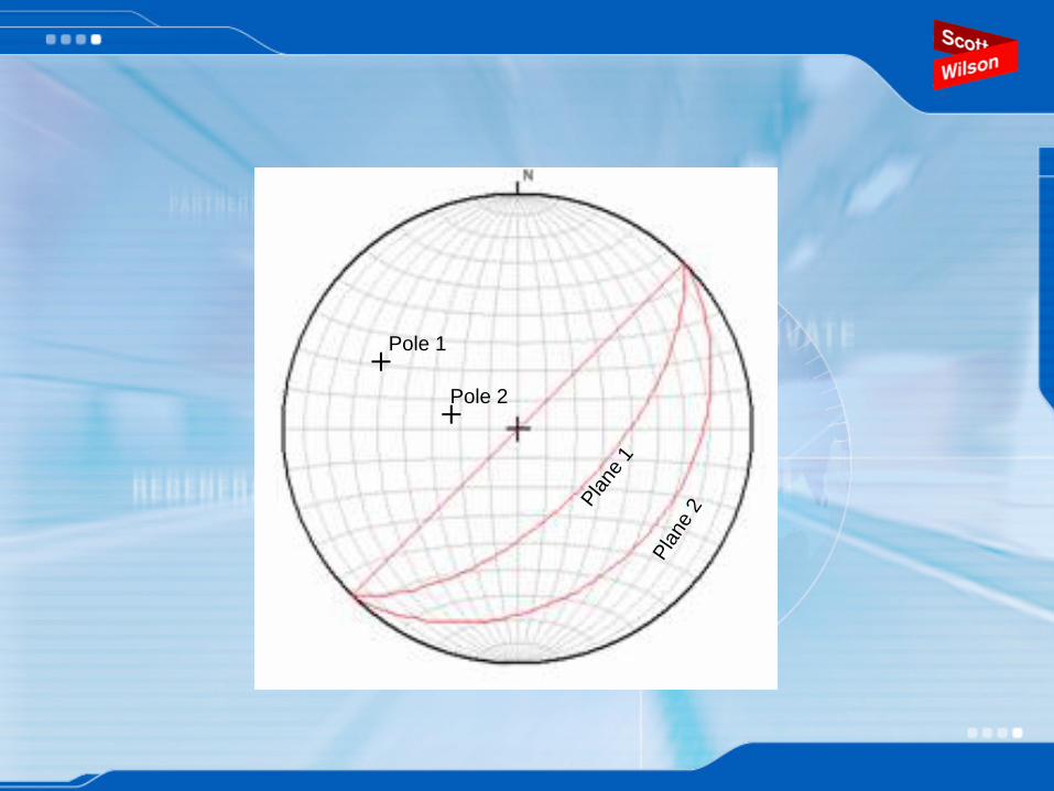
++
Plan
e 1
Plan
e 2
Pole 1
Pole 2
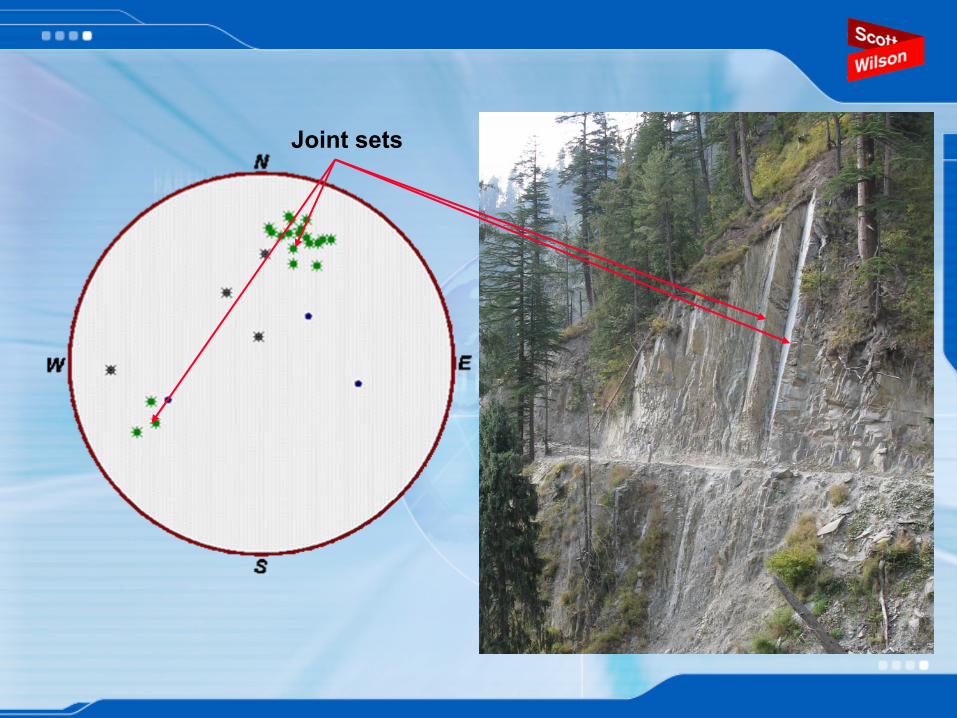
Joint sets
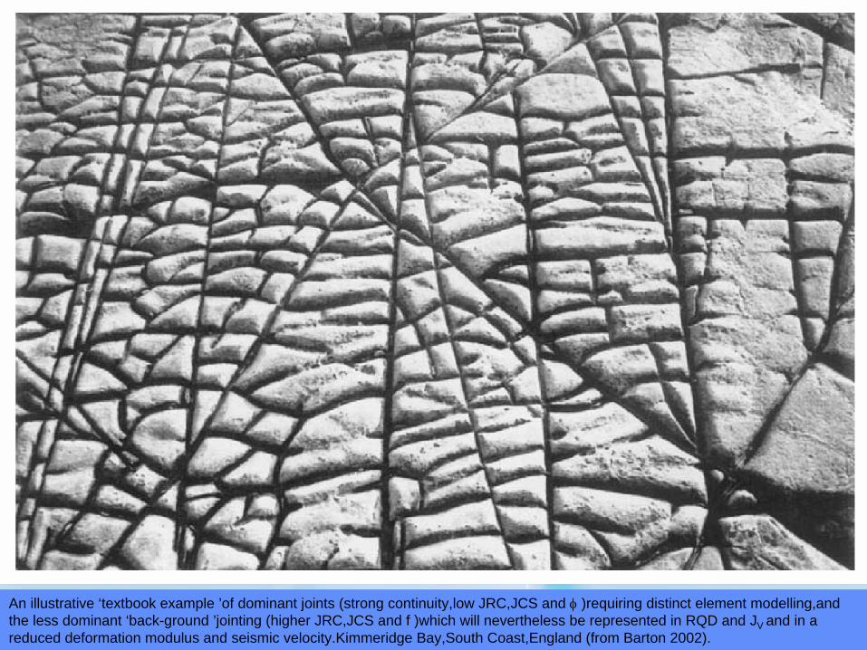
An illustrative ‘textbook example ’of dominant joints (strong continuity,low JRC,JCS and φ
)requiring distinct element modelling,and the less dominant ‘back-ground ’jointing (higher JRC,JCS and f )which will nevertheless be represented in RQD and JV and in a reduced deformation modulus and seismic velocity.Kimmeridge Bay,South Coast,England (from Barton 2002).
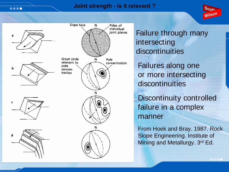
Joint strength -
is it relevant ?
Failure through many intersecting discontinuities
Failures along one or more intersecting discontinuities
Discontinuity controlled failure in a complex manner
From Hoek and Bray. 1987. Rock Slope Engineering. Institute of Mining and Metallurgy. 3rd Ed.
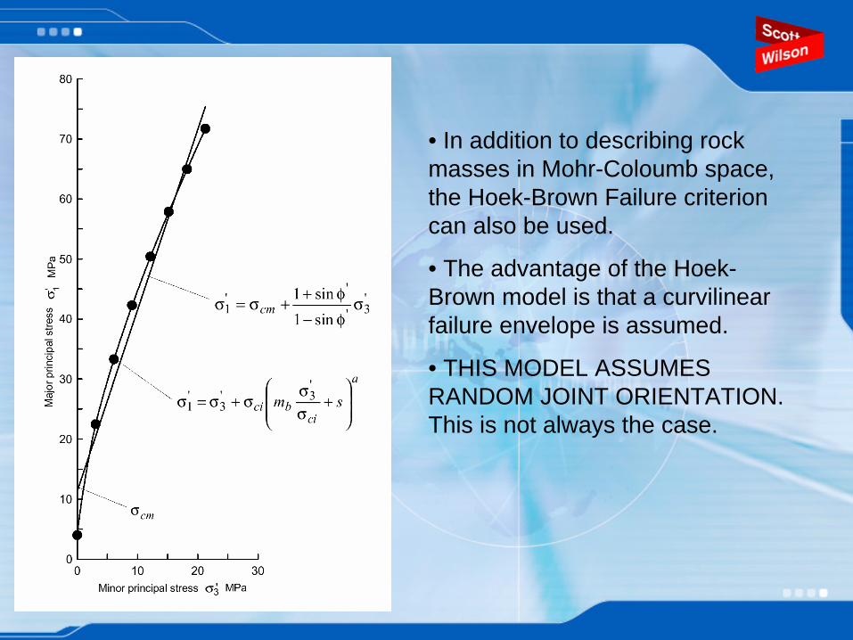
• In addition to describing rock masses in Mohr-Coloumb space, the Hoek-Brown Failure criterion can also be used.
• The advantage of the Hoek- Brown model is that a curvilinear failure envelope is assumed.
• THIS MODEL ASSUMES RANDOM JOINT ORIENTATION. This is not always the case.
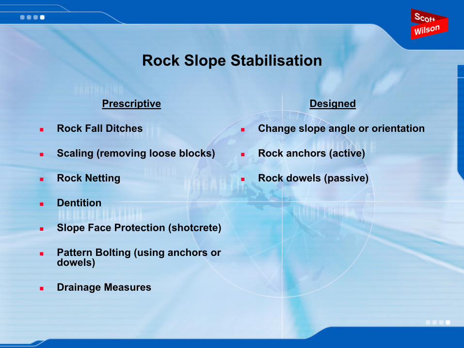
Rock Slope Stabilisation
Prescriptive
Rock Fall Ditches
Scaling (removing loose blocks)
Rock Netting
Dentition
Slope Face Protection (shotcrete)
Pattern Bolting (using anchors or dowels)
Drainage Measures
Designed
Change slope angle or orientation
Rock anchors (active)
Rock dowels (passive)
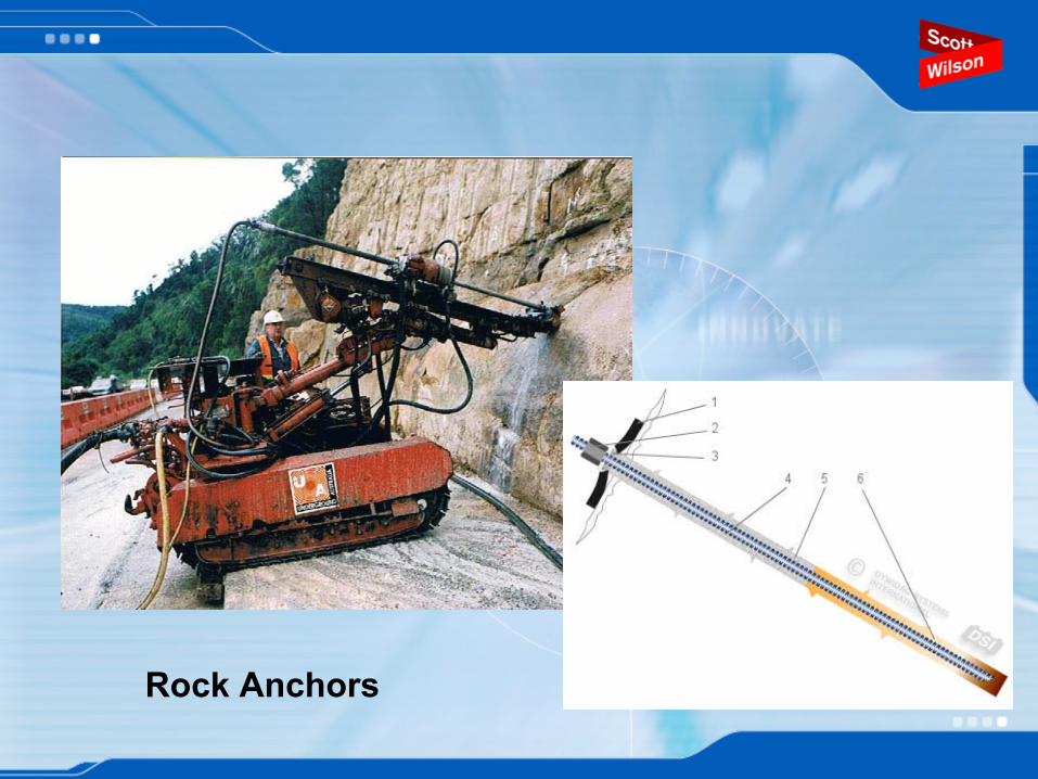
Rock Anchors
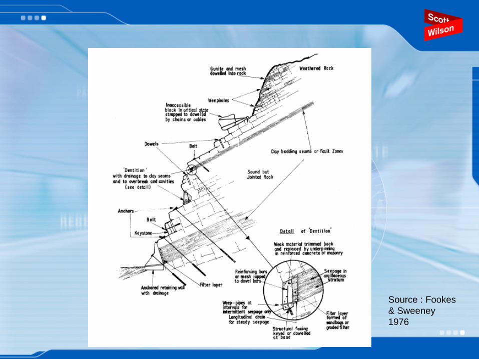
Source : Fookes & Sweeney 1976
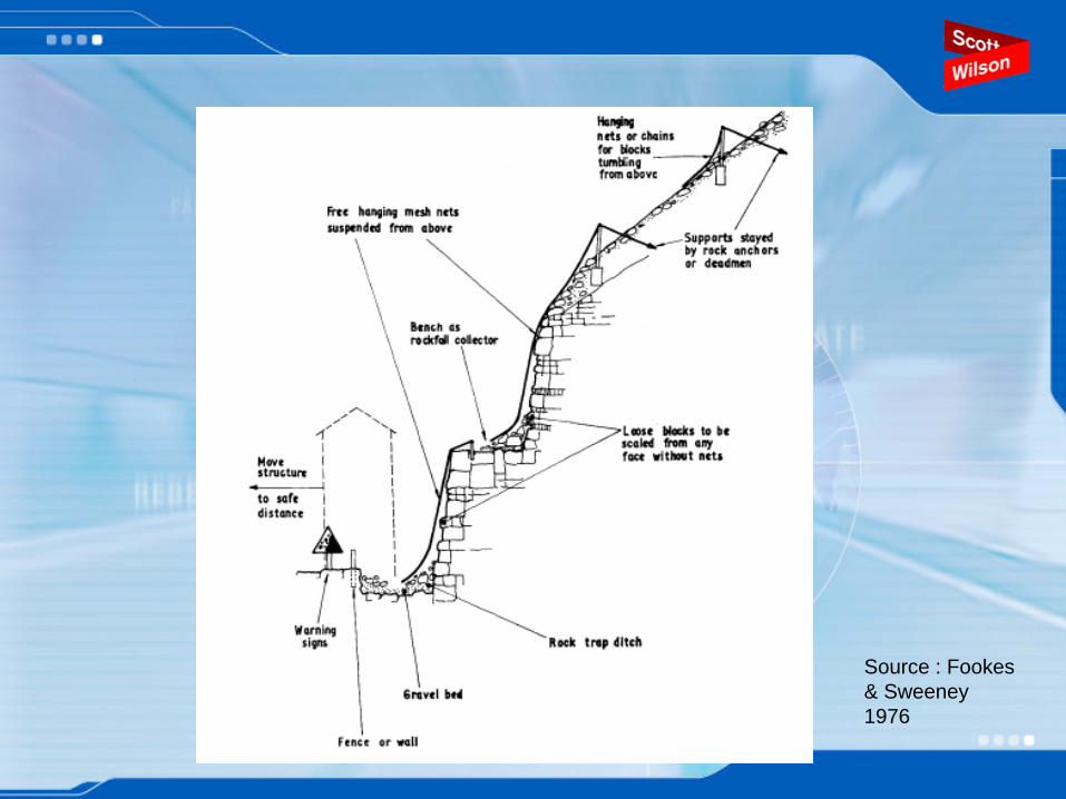
Source : Fookes & Sweeney 1976
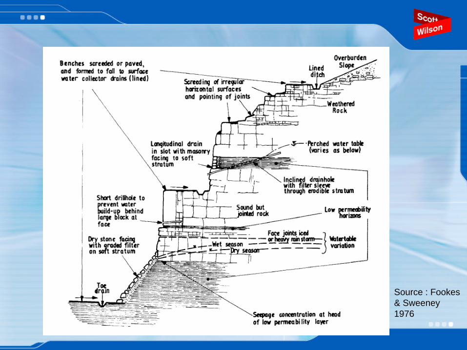
Source : Fookes & Sweeney 1976
Some references to read…..
Barton, N.R. 1976. The shear strength of rock and rock joints. International Journal of Rock Mechanics Mining Science & Geomechanics Abstracts. 13, 10, 1-24.Barton, N. 2002. Some new Q value correlations to assist in sitecharacterisation and tunnel design. International Journal of Rock Mechanics &Mining Sciences. 39, 185 –216 Barton, N.R. and Bandis, S.C. 1982. Effects of block size on the the shear behavior of jointed rock. 23rd U.S. symp. on rock mechanics, Berkeley, 739-760.Bhasin, R., Barton, N., Grimstad, E. & Chryssanthakis, P. 1995. Engineering Geological Characterization of low strength anisotropic rocks in the Himalayan Region for Assessment of Tunnel Support. Engineering Geology. 40, 169-193.Bieniawski, Z.T. 1973. Engineering classification of jointed rock masses. Trans S. African Institution of Civil Engineers 15, 335-344.Bieniawski Z.T. 1989. Engineering Rock Mass Classifications. Wiley, New York. Pp251Hoek E & Brown E.T., 1997. Practical estimates of rock mass strength.International Journal of Rock Mechanics and Minning Science. 34, 8 1165 –86.

Some references to read…..
Hudson JA, Harrison JP. 1992. A new approach to studying complete rock engineering problems. Quarterly Journal of Engineering Geology, 25, 93-105.Ozsan, A. & Akýn, M. 2002. Engineering geological assessment of the proposed Urus Dam, Turkey, Engineering Geology, 66 271–281Palmström, A. 1982. The volumetric joint count - a useful and simple measure of the degree of rock jointing. Proceedings of the 4th Congress of the International Association of Engineering Geologists, Delhi 5, 221-228.Priest S.D. & Hudson J.A. 1981. Estimation of discontinutiy spacing and trace length using scanline surveys. International Journal of Rock Mechanics, Mining Science & Geomechanics Abstracts. 18,183 –197.Toranoa, J., Rodriguez Diez, R., Rivas Cid, J. M. & Casal Barciella, M. M. 2002. FEM modeling of roadways driven in a fractured rock mass under a longwallinfluence Computers and Geotechnics, 29, 411 –431Wines, D. R. & Lilly, P. A. 2002. Measurement and analysis of rock mass discontinuity spacing and frequency in part of the Fimiston Open Pit operation in Kalgoorlie, Western Australia:a case study International Journal of Rock Mechanics &Mining Sciences. 39, 589 –602.
SEACAP 21 PROGRAMME
21/001 Slope Stabilisation Trials on R13N and 7
21/002 Feasibility Study for a National Slope Stability Management Programme
21/003 Mainstreaming Slope Stability Management into the NUoL Courses and MPWT
21/004 Mainstreaming Slope Stability Management – Hazard and Risk Assessment – to Laos Practitioners