Theater Missile Defense Extended Test Range Supplemental ...
163
Theater Missile Defense Extended Test Range Supplemental Environmental Impact Statement - Eglin Gulf Test Range July 1998 Prepared for: Thomas J. Kennedy, Major, USAF Director of Test, Theater Missile Defense 46 OG/OGM 205 West D Ave, Suite 241 Eglin AFB, FL 32542-6866 Volume 1 of 2 Final
Transcript of Theater Missile Defense Extended Test Range Supplemental ...
Theater Missile DefenseExtended Test RangeSupplemental Environmental Impact Statement - Eglin Gulf Test Range
July 1998
Prepared for:Thomas J. Kennedy, Major, USAFDirector of Test, Theater Missile Defense46 OG/OGM205 West D Ave, Suite 241Eglin AFB, FL 32542-6866
Volume 1 of 2
Final

COVER SHEET
THEATER MISSILE DEFENSE EXTENDED TEST RANGE
EGLIN GULF TEST RANGE FINAL SUPPLEMENTAL ENVIRONMENTAL IMPACT STATEMENT
a. Proponent: Ballistic Missile Defense Organization b. Cooperating Agencies: U.S. Air Force, U.S. Army, U.S. Navy, Federal Aviation Administration, U.S.
Coast Guard, and U.S. Fish and Wildlife Service. c. Proposed Action: The proposed action is to enhance the capability of the Eglin Gulf Test Range
(EGTR) to conduct Theater Missile Defense (TMD) programs. This document supplements the TMD Extended Test Range Final EIS (U.S. Army Space and Missile Defense Command, 1994) by identifying new launch and support locations, sensor operations, launch preparation activities, and missile flight tests and intercepts in the EGTR, encompassing the counties of Monroe, Gulf, Escambia, Santa Rosa, Okaloosa, Walton, Bay, and Franklin in the State of Florida.
d. Designation: Final Supplemental Environmental Impact Statement e. Public Review Process: The public review period for the Draft SEIS document was from
February 6, 1998, through April 3, 1998, and responses to all comments received during this period were incorporated in the Final SEIS. Public hearings were held during the week of March 9, 1998.
f. Abstract: The Ballistic Missile Defense Organization proposes to enhance the capability of the EGTR
to conduct TMD programs. The Proposed Action would include the selection and construction of land-launch facilities; modification of land, sea-surface, and airspace safety zones; the amendment of range operation and support management procedures; and the subsequent conduct of TMD missile system test and training flights within the enhanced EGTR. The preferred alternative would involve target and interceptor launch and support activities at Eglin Air Force Base (AFB) sites including Santa Rosa Island and Cape San Blas; Air Drop or air-launch of target missiles; and possible Navy AEGIS ship-launch of interceptor missiles. Alternatives would include target launch and support activities at alternative locations in the Florida Keys (Cudjoe Key or Saddlebunch Keys), target missile launch from a sea-launch vessel, and interceptor launch from offshore platforms off the coast of Santa Rosa Island and Cape San Blas. The No-action Alternative that does not provide extended test capabilities for TMD testing and training in the EGTR is also considered.
Potential environmental impacts associated with these actions are considered in the Final SEIS for the following categories: air quality, airspace use, biological resources, cultural resources, geology and soils, hazardous materials and wastes, land and water use, noise, safety, socioeconomics, transportation, utilities, visual aesthetics, and water resources.
g. Inquiries on this document should be directed to the Eglin Public Affairs Office:
Ms. Janet Tucker AFDTC/EM-PAV 501 Deleon St., Suite 101 Eglin AFB, FL 32542 (850) 882-4435

THIS PAGE INTENTIONALLY LEFT BLANK

Final TMD ETR SEIS—Eglin Gulf Test Range
FOREWORD
This Supplemental Environmental Impact Statement (SEIS) analyzes the potential environmental consequences of a proposal to enhance the Eglin Gulf Test Range (EGTR) to enable extended range testing and training operations using Theater Missile Defense (TMD) missile systems. TMD is designated to provide regional defenses against present and future conventional, chemical, biological, or nuclear ballistic, cruise, or air-to-surface guided missiles that can endanger deployed U.S. forces as well as U.S. friends and allies throughout the world. The proposal calls for the launch of target missiles from aircraft or land sites. These target missiles would be intercepted by interceptor missiles launched from ships or land sites. The intercepts would occur in the airspace over the Gulf of Mexico.
The proposed action would involve target and interceptor launch and support activities at alternative locations at Eglin Air Force Base (AFB) including Santa Rosa Island and Cape San Blas; Air Drop or air-launch of target missiles; and possible Navy AEGIS ship-launch. All intercepts would occur in the airspace over the Gulf of Mexico, which would also be the location for air-launches of target missiles and ship-launches of interceptors. Alternatives include target launch and support activities at alternative locations in the Florida Keys (Cudjoe Key or Saddlebunch Keys); target missile launch from a sea-launch vessel in the Gulf of Mexico; and interceptor launch from offshore platforms in the Gulf of Mexico off the coast of Santa Rosa Island or Cape San Blas.
The Final TMD Extended Test Range SEIS-EGTR has two volumes. The first volume includes an Executive Summary, Acronyms and Abbreviations, a Glossary, section 1 (Program Overview), section 2 (Description of Alternatives Including the Proposed Action), and section 3-4, numbered as section 3 (Affected Environment and Environmental Consequences and Mitigations). The second volume includes section 5 (Public Review Comments and Responses), section 6 (References), section 7 (List of Preparers), technical appendices, the distribution list, and the index.
Section 1 of the SEIS, Program Overview, presents the background, purpose, and need for the TMD Extended Test Range EGTR program. Section 2, Description of Alternatives Including the Proposed Action, describes the proposed action and the current available alternatives that have been identified as fulfilling the purpose and need of the program. A no-action alternative that does not provide extended test capabilities for TMD in the EGTR is also described in this section.
In this SEIS, the presentation of the Affected Environment and Environmental Consequences has been combined into a single section identified as section 3-4. In this unified section, the presentation of existing and future environmental baseline conditions for each of the 14 environmental resource areas is directly followed by a discussion of the potential impacts of the proposed project and alternatives, including appropriate mitigations.
Section 5 of the SEIS (Public Review Comments and Responses) describes how responses were made to the comments received from agencies and the public. This section contains copies of every comment received and responses to each.


Executive Summary

Final TMD ETR SEIS—Eglin Gulf Test Range ES-1
EXECUTIVE SUMMARY OVERVIEW
During the Gulf War, the United States needed a defense from Iraqi Scud missiles, which are short- to medium-range ballistic missiles. These types of short- to medium-range ballistic missiles are called theater ballistic missiles, as they are used in a limited theater of operations. During the Gulf War, Iraq launched over 90 of these missiles at our troops and allies, and civilian populations in Saudi Arabia and Israel. After the Gulf War, Congress directed the Department of Defense (DOD) to develop defensive systems effective against these theater ballistic missiles.
In order to ensure these defensive systems work the way they are designed, they must be thoroughly tested. This testing is done at each stage of the development. It includes computer modeling, component tests, and other simulations of the actual system components. However, to prove these systems will protect our troops, allies, and civilians, they need to be tested in actual conditions. This includes field testing away from the laboratories and factories using targets that look and act like actual theater ballistic missile threats. Without this realistic testing, there is no way to ensure these defensive weapons will be able to perform as planned. Further, once these systems are put into use by the armed forces, these soldiers, sailors, marines, and airmen will need to train using the actual systems against these simulated threat missiles.
The National Environmental Policy Act of 1969 (NEPA) requires Federal agencies to consider the impacts of their actions on the environment. Similarly, proposed actions outside the territorial boundaries of the United States must be evaluated in accordance with Executive Order 12114.
This Supplemental Environmental Impact Statement (SEIS) supplements the TMD Extended Test Range (ETR) Environmental Impact Statement (EIS). The TMD ETR EIS was completed in November 1994, with a Record of Decision (ROD) in March 1995. At that time, the EGTR was not selected, as there was no suitable target (sea-launched) launch capability. Since then, additional capabilities have been developed. This SEIS analyzes new launch and support locations, sensor operations, launch preparation activities, and missile flight tests and intercepts in the EGTR.
White Sands Missile Range in New Mexico is a missile test range with the capability to test using targets with flight distances up to 320 kilometers (199 miles). U.S. Army Kwajalein Atoll in the western Pacific is a longer missile test range with the capability to test using targets with flight distances greater than 1,100 kilometers (683 miles). The proposed Eglin Gulf Test Range (EGTR), with target launches from aircraft, would provide a medium flight distance of up to 600 kilometers (373 miles). Additionally, if national defense needs require target missiles with longer flights, the alternative of land-based targets from the Florida Keys would provide ranges up to 800 kilometers (497 miles) (figure ES-1).

Theater Ballistic MissileThreat DistancesCompared to TMDLand-, Sea-, and Air-launch Test Distances
Figure ES-1
es1
ES-2
Threat Theater Missile Flight Distances
EXPLANATIONAFBEGTR FIXFWDATBMTMDUSAKAWSMR
========
Air Force BaseEglin Gulf Test RangeFiring-In Extension Area (adjoining WSMR to the north)Fort Wingate Depot Activity, New MexicoTheater Ballistic MissileTheater Missile DefenseU.S. Army Kwajelein AtollWhite Sands Missile Range, New Mexico
Existing Land Launch Ranges based on TMD ETR EIS and ROD 1995
Alternatives Considered within the EGTR SEIS
FIX
FWDA
Wake Island
USAKA
WSMR
WSMR
Eglin AFB
Eglin AFB
Air-launch Locations
Eglin AFB
Sea Location
TargetMissileLaunchRanges
Florida KeysTarget Launch
Air Drop Location
Source: Ballistic Missile Defense Organization, 1996; U.S. Army Space and Strategic Defense Command, 1994A.
0 500 kilometers(311 miles)
1000 kilometers(621 miles)
AimPoint
Scud
Scud B
Al-HusseinNo-Dong
Possible ThreatMissile Launch
Ranges
kilometers
Final TMD ETR SEIS Eglin Gulf Test Range

Final TMD ETR SEIS—Eglin Gulf Test Range ES-3
The Final SEIS incorporates public and agency comments received during the public review of the Draft SEIS.
The director of the Ballistic Missile Defense Organization (BMDO) will choose some, all, or none of the alternatives for TMD programs at the EGTR based on several considerations. In addition to the environmental effects, other factors that will be considered include national policy, technical requirements, safety considerations, and cost. This decision could be to select an environmentally sensitive alternative because of strong national needs. Similarly, a technically preferred alternative might be eliminated due to environmental or cost concerns.
The preferred alternative includes target and interceptor launch and support activities at alternative locations at Eglin Air Force Base (AFB) test sites on Santa Rosa Island and Cape San Blas; air delivery (Air Drop or air-launch) of target missiles; and possible Navy AEGIS ship-launched interceptors. The Navy has no current plans to conduct TMD testing at the EGTR. Other alternatives considered include target launch and support activities at alternative locations in the Florida Keys (Cudjoe Key or Saddlebunch Keys), target missile launch from a sea-launch vessel, and interceptor launch from offshore platforms off the coast of Santa Rosa Island and Cape San Blas (table ES-1).
Table ES–1: Preferred Alternative and Other Alternatives Considered
Location Interceptor Launch Target Launch
Preferred Alternative
Santa Rosa Island X X
Cape San Blas X X
Ship-launch X
Air delivery (Air Drop or air-launch) X
Other Alternatives Considered
Platform X
Cudjoe or Saddlebunch Key X
Ship-launch X
For the purpose of this analysis, a total of up to 24 test or training events per year
are being considered over a 10-year period. These test or training events could include up to 48 interceptor launches per year from a combination of launch sites, land, ship, and/or platform. Concurrent with the interceptor launches would be up to 24 target launches per year from a complementary launch site. However, should the Florida Keys Alternative be selected, no more than 12 targets would be launched per year. The number of tests in the EGTR is likely to be considerably less than 24 per year. Also, a 10-year period is used only to analyze cumulative impacts.
There are several interceptors being considered for this proposal (figure ES-2). For the purpose of this analysis, the PATRIOT Advanced Capability-3 is used to represent the

es2
TMD MissileComparison
Figure ES-2
EXPLANATION
ATACMSPAATPACSMTHAADMft
=======
Army Tactical Missile SystemPATRIOT as a TargetPATRIOT Advanced CapabilityStandard MissileTheater High Altitude Area DefenseMeters Feet
0
5
10
15
Hu
ma
n
Ha
wk
SM
-3
ME
AD
S
SM
-2 B
loc
k IV
A
TH
AA
D
PA
C-3
5.2 M(17.1 ft)
PA
AT
PA
C-2
5.3 M(17.4 ft)
5.3 M(17.4 ft)
Meters
TMD Targets
Interceptors
6.2 M(20.3 ft)
6.5 M(21.4 ft)
6.6 M(21.5 ft)
5.0 M(16.4 ft)
5.0 M(16.4 ft)
1.8 M(6.0 ft)
Pe
ga
su
s
15.5 M(50.8 ft)
2 S
tag
e H
era
Bla
ck
Bra
nt
9
13.58 M(44.54 ft)
12.2 M(40.0 ft)
ST
OR
M II
13.28 M(43.56 ft)
La
nc
e
6.14 M(20.14 ft)
He
rme
s(A
TA
CM
S)
4.0 M(13.1 ft)
Source: U.S. Army Space and Strategic Defense Command, Test and Evaluation Office, 1995.
ES-4
Final TMD ETR SEIS Eglin Gulf Test Range

Final TMD ETR SEIS—Eglin Gulf Test Range ES-5
land-launched and platform-based interceptors. The Navy STANDARD Missile 2 Block IVA will represent the sea-based interceptor.
Maximum use of existing infrastructure and facilities would be made at interceptor launch locations.
Several target missiles are being considered for this proposal (figure ES-2). For the purpose of this analysis, the Hera represents the land-launched target missile that is common to all proposed launch locations. The Hera is a two-stage solid propellant missile constructed of the upper two stages of a Minuteman II. The Lance is proposed as a target from either Santa Rosa Island or Cape San Blas. The Lance is a single-stage, pre-fueled liquid propellant missile. The STORM represents the type of target that would be used from an Air Drop platform. The STORM is a single-stage solid propellant missile.
The activities supporting a target missile launch would be the same at any of the proposed locations. Several facilities would be required to support the target launch. One of the facilities is a Missile Assembly Building. This is where the missile would be assembled after each component is trucked to the site. A concrete launch pad would be required. Also, a Launch Operations Trailer Shelter, a large concrete garage, is required to protect the mobile electronic and safety instrumentation trailers that have to be near the launch location.
Missile preparation would require a team of up to 50 personnel onsite over a 2- to 4-week period. Another 30 to 60 people would support the various portable radar, radio, and safety systems that would be stationed within 32.2 kilometers (20 miles) of the proposed launch location. After the test, most of the people would leave immediately, with the last group leaving within a week of the launch.
Four potential test examples are shown here (figure ES-3). The first example is an Air Drop target with a land-launched interceptor from Santa Rosa Island. The second example is a land-launched target from Cape San Blas with a ship-launched interceptor. The third example shows a land-launched target from the Florida Keys with an interceptor from a platform off Cape San Blas. The fourth example represents a systems integration test that combines many targets and interceptors to ensure all of the command and control systems work together against several threats at once. This type of systems integration test would occur approximately once every 2 to 3 years.
In addition to the proposed locations, the SEIS evaluates the no-action alternative. This is the result should the proposed action to enhance the EGTR for TMD testing not be selected. All of the currently planned test and training activities at Eglin AFB, Naval Air Station Key West, and other military facilities would not be affected.
Some land launched target alternatives were analyzed and subsequently eliminated from further consideration (table ES-2). They are shown here with the primary rationale that eliminated them from further consideration.

Mississippi Alabama Georgia
Florida
Gulf of Mexico
AtlanticOcean
I
CapeSan Blas
Land Launch
Ship
T
es3
Test and TrainingExamples
Figure ES-3
EXPLANATION
Mississippi Alabama Georgia
Florida
Gulf of Mexico
AtlanticOcean
I
T
CapeSan Blas
Platform Launch
Mississippi Alabama Georgia
Florida
Gulf of Mexico
AtlanticOcean
Air Drop
I
T
Santa RosaIsland
Mississippi Alabama Georgia
Florida
Gulf of Mexico
AtlanticOcean
CapeSan Blas
T T
Ship
Santa RosaIsland
I
I
I
Air Drop
Example 3 - Trajectory of RepresentativeLand-launched Target From the Florida KeysIntercepted by Platform Launched InterceptorFrom Eglin AFB
Example 1 - Trajectory of RepresentativeAir Dropped Target Intercepted byLand-launched Interceptor
Example 2 - Trajectory of RepresentativeLand-launched Target Intercepted bySea-launched Interceptor
I Interceptor Ground Track
T Target Ground Track
Intercept
Interceptor Debris
Target Debris
Representative EvacuationAreas
Launch Hazard Area
Booster Drop Zone
Example 4 - Trajectory of Representative Shipand Air Delivered Targets Intercepted by MultipleInterceptors From Eglin AFB
Coordinating Final TMD ETR SEIS Eglin Gulf Test Range
ES-6
Final TMD ETR SEIS—Eglin Gulf Test Range ES-7
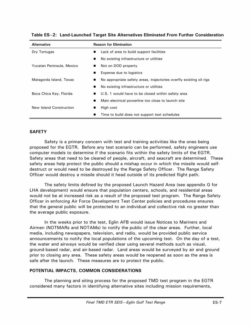
Table ES–2: Land-Launched Target Site Alternatives Eliminated From Further Consideration
Alternative Reason for Elimination
Dry Tortugas Lack of area to build support facilities
No existing infrastructure or utilities
Yucatan Peninsula, Mexico Not on DOD property
Expense due to logistics
Matagorda Island, Texas No appropriate safety areas, trajectories overfly existing oil rigs
No existing infrastructure or utilities
Boca Chica Key, Florida U.S. 1 would have to be closed within safety area
Main electrical powerline too close to launch site
New Island Construction High cost
Time to build does not support test schedules
SAFETY
Safety is a primary concern with test and training activities like the ones being proposed for the EGTR. Before any test scenario can be performed, safety engineers use computer models to determine if the scenario fits within the safety limits of the EGTR. Safety areas that need to be cleared of people, aircraft, and seacraft are determined. These safety areas help protect the public should a mishap occur in which the missile would self-destruct or would need to be destroyed by the Range Safety Officer. The Range Safety Officer would destroy a missile should it head outside of its predicted flight path.
The safety limits defined by the proposed Launch Hazard Area (see appendix G for LHA development) would ensure that population centers, schools, and residential areas would not be at increased risk as a result of the proposed test program. The Range Safety Officer in enforcing Air Force Development Test Center policies and procedures ensures that the general public will be protected to an individual and collective risk no greater than the average public exposure.
In the weeks prior to the test, Eglin AFB would issue Notices to Mariners and Airmen (NOTMARs and NOTAMs) to notify the public of the clear areas. Further, local media, including newspapers, television, and radio, would be provided public service announcements to notify the local populations of the upcoming test. On the day of a test, the water and airways would be verified clear using several methods such as visual, ground-based radar, and air-based radar. Land areas would be surveyed by air and ground prior to closing any area. These safety areas would be reopened as soon as the area is safe after the launch. These measures are to protect the public.
POTENTIAL IMPACTS, COMMON CONSIDERATIONS
The planning and siting process for the proposed TMD test program in the EGTR considered many factors in identifying alternative sites including mission requirements,

ES-8 Final TMD ETR SEIS—Eglin Gulf Test Range
cost, environmental conservation, human and ecological health, and land use compatibility. All of the potential environmental impacts identified in the SEIS were based on preliminary planning generally representing the maximum disturbance of existing sites. If any of the preferred or alternative sites are selected for TMD testing, close consultation and coordination with Federal and state resource agencies would continue to ensure the avoidance or minimization of potential impacts. The environmental criteria for the final planning and design process would be to avoid adverse impacts to the extent possible, to minimize potential impacts when avoidance is not possible, and to mitigate or offset potential long-term adverse effects. Adverse impacts represent potential environmental impacts that have a measured severity extent, or duration that could require the application of appropriate mitigations. The potential impacts by resource areas are shown in table ES-3.
Should an alternative be selected, the specific mitigations to avoid or minimize potential environmental impacts will be identified in the Record of Decision. A mitigation plan, prepared in consultation with Federal and state resource agencies, will be developed and implemented prior to initial site preparation and test activities.
In every test example proposed for the EGTR, the intercept would occur over the open water of the Gulf of Mexico and the debris from the intercept would land in the Gulf of Mexico. Large areas of the Gulf of Mexico would be closed to watercraft and aircraft during a test event to allow the debris to safely impact the water.
SANTA ROSA ISLAND
The proposed location on Santa Rosa Island is an existing Eglin AFB test site known as Site A-15. This site was used from 1959 until 1984 as a missile launch site for the Boeing Michigan Aeronautical Research Center (BOMARC) missile. After that, the Strategic Defense Initiative Organization built facilities to test an electromagnetic railgun. Currently, Site A-15 is minimally manned with Wright Laboratories personnel performing small tests in several of the buildings onsite.
There are no adverse impacts identified for either interceptor or target launches at Site A-15.
CAPE SAN BLAS
The proposed location on Cape San Blas is an existing Eglin AFB test site known as Site D-3A. This site has been used in the past to launch small missiles and rockets. It was also used in 1995 to launch PATRIOT missiles in surface-to-air intercept test.
There are no adverse impacts identified for interceptor launches.
There are several potential adverse impacts associated with target launches at Site D-3A:
There is a historic lighthouse and keeper’s quarters within the proposed Launch Hazard Area. The lighthouse lens and the quarters may be damaged by noise vibrations during target missile launches. Potential mitigation

Final TMD ETR SEIS—Eglin Gulf Test Range ES-9
measures include methods to protect the lens in place, removal of the lens, refurbishment of the quarters, and/or relocation of the quarters.
Current safety instrumentation would require a large corridor to be cut through the forested area 1,676 by 12.2 meters (5,500 by 40 feet). This corridor would be within 23 meters (75 feet) of a bald eagle’s nest. This violates the U.S. Fish and Wildlife Service’s recommended standoff distance of 600 meters (1968 feet). Potential mitigation measures include moving the nest or developing alternate methods to collect the safety data.
Cape San Blas has the highest concentration of sea turtle nesting in northwest Florida. Launch operations could reduce the number of successful hatchings. Potential mitigation measures include using low pressure sodium lighting for nighttime operations, and/or monitoring nests for successful hatch rates.
Target launch facilities would result in the permanent loss of 0.6 hectare (1.6 acres) of wetlands. Potential mitigation measures include in-kind enhancement or restoration of currently disturbed wetland areas near Site D-3A.
TESTING OVER THE GULF OF MEXICO
All TMD flight tests and intercepts would occur over the Gulf of Mexico in the EGTR. Navy interceptor launches, Air Drop, and air-launched targets would be launched over the Gulf of Mexico. Also, interceptor platform launches and ship-launched targets would originate over the Gulf of Mexico. During flight tests, the defined Launch Hazard Area would be cleared of air and sea traffic for a period of up to 4 hours. This would result in some delays, and potentially some economic loss, to commercial shipping, fishing, and air transportation.
It is uncertain where and when oil and gas exploration activities would be conducted in the areas of the Gulf of Mexico potentially affected by the TMD test program. Prior to oil and gas activities, appropriate environmental documentation for these projects would need to evaluate all environmental issues including the presence of TMD and other military activities in the Gulf. A Memorandum of Agreement would be developed with the Minerals Management Service (MMS) to coordinate TMD testing and oil and gas activities in the Eglin Gulf Test Range. Procedures for scheduling, notification, clearance, and mitigation for TMD launch activities would be developed in cooperation with MMS and other Federal resource agencies.
Booster drops, intercept debris, and sonic booms generated by the TMD test program could potentially affect marine mammals in the Gulf of Mexico. There is the potential that sonic booms created by target missiles reentering the atmosphere could penetrate the water. This may result in the harassment of some marine mammals. This potential impact is being analyzed by a consortium of Federal and state agencies.

ES-10 Final TMD ETR SEIS—Eglin Gulf Test Range
FLORIDA KEYS
Two separate areas in the Florida Keys are other alternatives considered to provide a target launch from the southern Gulf of Mexico—Saddlebunch Keys, and Cudjoe Key. It is unlikely that this alternative will be chosen. The possibility of using a launch site in the Florida Keys remains if a national need develops. The property of either alternative Keys site is currently military land, and is recognized as such in the Florida Keys National Marine Sanctuary Management Plan.
The proposed site preparation and pre-flight activities, although an increase, would not affect the adjacent land uses. Flight test activities would cause increased site occupation and activity, a short-term high noise level, and a visible emissions trail. Flight test activities would include clearing land and water areas of non-mission-essential personnel for periods of no more than 4 hours a month.
There is considerable concern about the environment around the Florida Keys. This concern is the primary reason this alternative is in the Other Alternatives Considered category; specifically, potentially adverse impacts at the Saddlebunch Keys location. This location would result in the permanent loss of up to 0.9 hectare (2.2 acres) of wetlands. A potential mitigation measure would be in-kind wetland restoration.
CUMULATIVE IMPACTS
Cumulative impacts consider the impacts of the proposed action plus those of other reasonably foreseeable activities. Using 10 years to analyze the cumulative impacts, few impacts beyond those identified for individual test events were found.
Depending on the specific resource, cumulative impacts may or may not be additive in nature. Environmental monitoring at Kennedy Space Center over 10 years of Space Shuttle launches has shown that normal pH levels and metal concentrations in adjacent water bodies have returned to pre-launch levels within 24 to 72 hours with no long-term changes. However, settling of exhaust particles on soils near the launch pad has caused some small but permanent changes in local plant diversity and cover. Although the predicted settling from TMD testing will be less than 1 percent of the settling rates for the Space Shuttle, it is possible that similar changes in local plant diversity and vegetation cover could occur within a 60-meter (197-foot) radius of the proposed target launch sites. During flight test events, some small-scale animal habitat destruction, frightening of animals, and incidental death could occur near the launch area. However, the continued existence of local plant and wildlife species would not be jeopardized as a result of TMD programs.
CONCLUSIONS
The purpose of this SEIS is to analyze the potential environmental impacts of implementing TMD testing and training activities in the EGTR. The director of the BMDO will use this information along with other considerations to decide whether or not to proceed with enhancing the EGTR for TMD programs.

Final TMD ETR SEIS—Eglin Gulf Test Range ES-11
The information in this document has come from many sources. This information is now available in one document to the DOD, the State of Florida, local governments, and the general public for their future planning efforts.
REPOSITORIES
The Draft and Final SEIS, as well as the 1994 Theater Missile Defense Extended Test Range EIS, are available at the following public libraries:
Okaloosa-Walton Community College Monroe County Public Library– Library–Niceville Campus George Dolezal Public Library Branch 100 College Boulevard 3251 Overseas Highway Niceville, FL 32578 Marathon, FL 33050 (850) 729-5395 (305) 743-5156
Okaloosa–Walton Community College Monroe County Public Library– Library/UWF–Fort Walton Beach Campus Main Branch 1170 King Boulevard 700 Fleming Street Fort Walton Beach, FL 32547 Key West, FL 33040 (850) 863-6578 (305) 294-8488
Gulf County Library Florida Keys Community College Library 110 Library Drive 5901 West College Road Highway 71 North Key West, FL 33040 Port St. Joe, FL 32456 (305) 296-9081 (850) 229-8879
Key Largo Public Library Manoa Public Library 101485 Overseas Highway 2716 Woodlawn Drive Key Largo, FL 33037 Honolulu, HI 96822 (305) 451-2396 (808) 988-6655

imp-es1-002a
Noise
Safety
Socio-economics
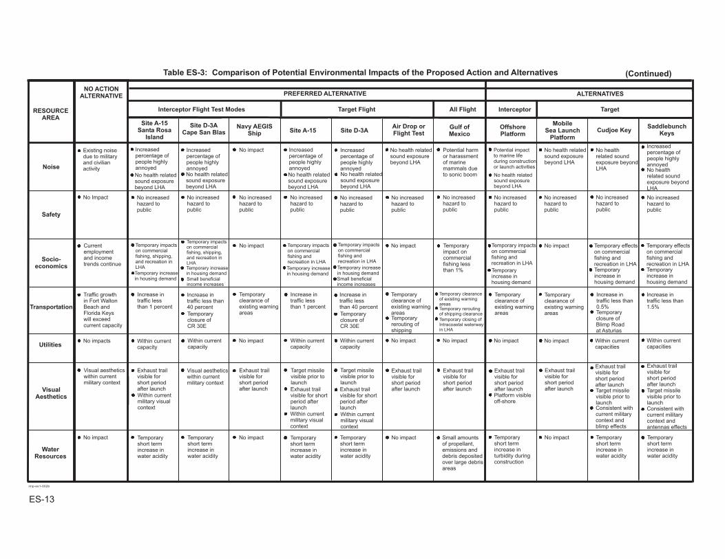
Table ES-3: Comparison of Potential Environmental Impacts of the Proposed Action and Alternatives
RESOURCEAREA
NO ACTIONALTERNATIVE PREFERRED ALTERNATIVE ALTERNATIVES
Interceptor Flight Test Modes Target Flight All Flight Interceptor Target
Site A-15Santa Rosa
Island
Air Quality
Airspace Use
BiologicalResources
CulturalResources
Geologyand
Soils
HazardousMaterials
andWaste
Site D-3ACape San Blas
Navy AEGISShip Site A-15 Site D-3A
Air Drop orFlight Test
Gulf ofMexico
OffshorePlatform
MobileSea Launch
PlatformCudjoe Key
SaddlebunchKeys
Land andWater Use
Within NAAQS
No Impact
T&E Speciesprotected byNatural Resourcesmanagementpractices
Cape San BlasKeeper’s Quartersthreatened byerosion andnaturaldeterioration
Cape San Blasaffected bycoastal erosionand naturaldeterioration
Within allowablelimits
Within allowablelimits
Within allowablelimits
Within allowablelimits
Within allowablelimits
Within allowablelimits
Within allowablelimits
Within allowablelimits
Within allowablelimits
Within allowablelimits
Within allowablelimits
Compatible withcurrent militaryland/gulf use
Within NAAQS
No healthexposure
Temporarydisturbance towildlife from sitepreparation andlaunch activities
Temporarydisturbance towildlife from sitepreparation andlaunch activities
Temporarydisturbance towildlife from sitepreparation andlaunch activities
Temporary disturbanceto wildlife from sitepreparation andlaunch activities
No impact No impact Site preparationmay affectBOMARCfacilitiespotentiallyeligible forNRHP listing
Small depositionof aluminumoxide andhydrogenchloride onsoils
Small depositionof aluminumoxide andhydrogenchloride on soils
Small depositionof aluminumoxide andhydrogenchloride on soils
Small depositionof aluminumoxide andhydrogenchloride on soils
Small depositionof aluminum oxideand hydrogenchloride on soils
Small depositionof aluminumoxide andhydrogenchloride on soils
Compatible withOkaloosa CountyComp. Plan andEglin AFB Plan
Compatible withOkaloosa CountyComp. Plan andEglin AFB Plan
Temporary clearanceof recreationareas in LHA
Temporary clearanceof recreationareas in LHA
Compatible with GulfCounty Comp. Planand Eglin AFB Plan
Compatible with GulfCounty Comp. Planand Eglin AFB Plan
Temporary closureof CR 30E
Temporary closureof CR 30E
Temporaryclearance ofexisting warningareas
Potential impacton oil and gasexplorationTemporaryclearance ofexisting marineareas
Potential impacton oil and gasexplorationTemporaryclearance ofexisting marineareas
No healthexposure
Within NAAQSNo healthexposure
Meets NAAQS
No healthexposure
Within NAAQSNo healthexposure
Within NAAQS
No healthexposure
Meets NAAQSNo healthexposure
Meets NAAQS
No healthexposure
Meets NAAQSNo healthexposure
Meets NAAQS
No healthexposure
Within NAAQS
No healthexposure
Within NAAQS
CFA would notimpact air trafficin the east-westcorridor
CFA would notimpact air trafficin the area
CFA would notimpact air trafficin the east-westcorridor
CFA would notimpact air trafficin the area
CFA would notimpact air trafficin the area
CFA would notimpact air trafficin the area
Temporaryclearance ofexistingwarning areas
Temporaryclearance ofexistingwarning areas
Temporary impactto sea floorhabitat duringconstruction
Temporaryrerouting ofair traffic
Temporaryrerouting ofair traffic
Temporaryclearance ofexistingwarning areas
Temporaryclearance ofexistingwarning areas
Temporaryclearance ofexistingwarning areas
No impact
No impact
No impact
Potential adverseeffect tolighthouse fromtarget launchnoise levels
Adverse impact tobald eagle and seaturtle nesting
Adverse impacteliminates 1.6 acresof wetland
Adverse impacteliminates 2.2acres of wetland
Potential impactto marinemammals dueto launch supportequipment
Potential impactto marinemammals dueto missile reentry
Temporarydisturbance towildlife from sitepreparation andlaunch activities
Temporarydisturbance to wildlifefrom site preparationand launch activities
Potential adverseimpact to sensitivespecies and habitat
No impactSmall impact tosea floor duringconstruction
Potentialbeneficial impactto marine life
Small amountsof hazardousmaterials overlarge areas ofthe Gulf
Temporaryclearance ofexistingmarine areas
Temporaryclearance ofexistingmarine areas
Temporary clearanceof water basedactivities recreationalareas in LHA
Temporary clearanceof water basedactivities recreationalareas in LHA
Potentialbeneficial impactas artificial reefhabitat
No impact
No impactNo impact
No impactNo impact
No impact No impact
Temporarysingeing ofvegetation
Temporary singeingof vegetation
Site preparationmay affectAerostat facilitiespotentiallyeligible forNRHP listing
Site preparationmay affectsubmergedprehistoric sitesor shipwrecks
Not Compatible withMonroe County Comp.Plan
Not Compatible withMonroe County Comp.Plan
LHA overlaps 7 parcelsof non-federal land
LHA overlaps 5 parcelsof non-federal land
LHA overlaps 5non-federal parcels
LHA overlaps 5non-federal parcels
Adverse impacteliminates 1.6acres of wetland
Adverse impacteliminates 2.2acres of wetland
Temporary singeingof vegetation
ES-12
imp-es1-002b
Table ES-3: Comparison of Potential Environmental Impacts of the Proposed Action and Alternatives (Continued)
RESOURCEAREA
NO ACTIONALTERNATIVE PREFERRED ALTERNATIVE ALTERNATIVES
Interceptor Flight Test Modes Target Flight All Flight Interceptor Target
Site A-15Santa Rosa
Island
Noise
Safety
Socio-economics
Transportation
Utilities
VisualAesthetics
Site D-3ACape San Blas
Navy AEGISShip Site A-15 Site D-3A
Air Drop orFlight Test
Gulf ofMexico
OffshorePlatform
MobileSea Launch
PlatformCudjoe Key
SaddlebunchKeys
WaterResources
Existing noisedue to militaryand civilianactivity
No Impact
Currentemploymentand incometrends continue
Traffic growthin Fort WaltonBeach andFlorida Keyswill exceedcurrent capacity
No impacts
Visual aestheticswithin currentmilitary context
Visual aestheticswithin currentmilitary context
Exhaust trailvisible forshort periodafter launch
Exhaust trailvisible forshort periodafter launch
Exhaust trailvisible forshort periodafter launch
Within currentmilitary visualcontext
Within currentmilitary visualcontext
Within currentmilitary visualcontext
Exhaust trailvisible forshort periodafter launch
Target missilevisible prior tolaunch
Target missilevisible prior tolaunch
Exhaust trailvisible forshort periodafter launch
Exhaust trailvisible forshort periodafter launch
Exhaust trailvisible forshort periodafter launchPlatform visibleoff-shore
Exhaust trailvisible forshort periodafter launch Target missile
visible prior tolaunch
Target missilevisible prior tolaunch
Increasedpercentage ofpeople highlyannoyed
Increasedpercentage ofpeople highlyannoyed
Increasedpercentage ofpeople highlyannoyed
Increasedpercentage ofpeople highlyannoyed
Increasedpercentage ofpeople highlyannoyed
Temporary impactson commercialfishing, shipping,and recreation inLHA
Temporary impactson commercialfishing, shipping,and recreation inLHA
Temporary impactson commercialfishing andrecreation in LHA
Temporary impactson commercialfishing andrecreation in LHA
Increase intraffic lessthan 1 percent
Increase intraffic lessthan 1 percent
Increase intraffic lessthan 40 percent
Within currentcapacity
Within currentcapacity
Within currentcapacity
Within currentcapacity
Temporaryshort termincrease inwater acidity
No impact Temporaryshort termincrease inwater acidity
Temporaryshort termincrease inwater acidity
Temporaryshort termincrease inwater acidity
No impact No impact Small amountsof propellant,emissions anddebris depositedover large debrisareas
No impact Potential harmor harassmentof marinemammals dueto sonic boom
Potential impactto marine lifeduring constructionor launch activities
No healthrelated soundexposure beyondLHA No health
related soundexposure beyondLHA
No increasedhazard topublic
Temporary impactson commercialfishing andrecreation in LHA
Temporary effectson commercialfishing andrecreation in LHA
Temporary effectson commercialfishing andrecreation in LHA
Temporaryimpact oncommercialfishing lessthan 1%
No impact No impact
Temporaryclearance ofexisting warningareas
No impact
Increase intraffic less than40 percent
Temporary clearanceof existing warningareas
Temporaryclearance ofexisting warningareas
No impact Within currentcapacities
Within currentcapacities
Temporaryshort termincrease inturbidity duringconstruction
No impact Temporaryshort termincrease inwater acidity
Temporaryshort termincrease inwater acidity
No increasedhazard topublic
No increasedhazard topublic
No increasedhazard topublic
No increasedhazard topublic
No increasedhazard topublic
No increasedhazard topublic
No increasedhazard topublic
No increasedhazard topublic
No increasedhazard topublic
No increasedhazard topublic
Temporaryincrease inhousing demand
Temporaryincrease inhousing demand
Temporaryincrease inhousing demand
No impact
No impact No impact No impact
Increase intraffic less than0.5%
Increase intraffic less than1.5%
Temporaryclearance ofexisting warningareas
Temporary closing ofIntracoastal waterwayin LHA
Temporaryclearance ofexisting warningareas
No health relatedsound exposurebeyond LHA
No health relatedsound exposurebeyond LHA
No health relatedsound exposurebeyond LHA
No health relatedsound exposurebeyond LHA
No health relatedsound exposurebeyond LHA
No health relatedsound exposurebeyond LHA
No health relatedsound exposurebeyond LHA
Temporary increasein housing demand
Temporary increasein housing demand
Temporary increasein housing demand
Temporary increasein housing demand
Small beneficialincome increases
Small beneficialincome increases
Temporaryclosure ofCR 30E
Temporaryclosure ofCR 30E
Temporary reroutingof shipping clearance
Temporaryrerouting ofshipping
Exhaust trailvisible for shortperiod afterlaunch
Exhaust trailvisible for shortperiod afterlaunch Consistent with
current militarycontext andblimp effects
Consistent withcurrent militarycontext andantennas effects
Temporaryclosure ofBlimp Roadat Asturias
ES-13

Acronyms, Abbreviations,and Glossary
Final TMD ETR SEIS—Eglin Gulf Test Range
ACRONYMS AND ABBREVIATIONS AADT Annual Average Daily Traffic
AAQS Ambient Air Quality Standards
ACHP Advisory Council on Historic Preservation
AFB Air Force Base
AFDTC Air Force Development Test Center
AFM Air Force Manual
AFOSH Air Force Occupational Safety and Health
AGL Above Ground Level
AICUZ Air Installation Compatible Use Zone
AIWW Atlantic Intracoastal Waterway
ALTRV Altitude Reservation
ANSI American National Standards Institute
AOC Areas of Concern
ARTCC Air Route Traffic Control Center
ASRM Advanced Solid Rocket Motor
AST Aboveground Storage Tank
ATACMS Army Tactical Missile System
BEQ Bachelor Enlisted Quarters
BMDO Ballistic Missile Defense Organization
BOE Bureau of Explosives
BOMARC Boeing Michigan Aeronautical Research Center
BOQ Bachelor Officer’s Quarters
BRAC Base Realignment and Closure
C Celsius
CHRIMP Consolidated Hazardous Material Reutilization and Inventory Management Program
C3 Command, Control, and Communication
CAA Clean Air Act
CCF Central Control Facility
CDNL C-weighted Day-Night Equivalent Sound Level

Final TMD ETR SEIS—Eglin Gulf Test Range
CEQ Council on Environmental Quality
CESQC Conditionally-Exempt Small Quantity Generator
CFA Controlled Firing Area
CFR Code of Federal Regulations
CWA Clean Water Act
CTA Control Area
CZMA Coastal Zone Management Act
DARM Department of Air Resource Management
dB Decibel
dBA Decibel, A-weighted
DCA Department of Community Affairs (Florida)
DEM Department of Environment Management
DNL Day-Night Average Noise Level
DOCD Development Operations Coordination
DOD Department of Defense
DRMO Defense Reutilization Marketing Office
EA Environmental Assessment
ECAC Electronic Compatibility Analysis Center
EDT Eastern Daylight Time
EGOM Eastern Gulf of Mexico
EGTR Eglin Gulf Test Range
EIS Environmental Impact Statement
EMC Environmental Management Compliance
EMI Electromagnetic Inference
EMR Electromagnetic Radiation
EO Executive Order
EOP Eglin Operating Procedures
EP Exploration Plan
EPCRA Emergency Planning and Community Right-to-Know Act
ERINT Extended Range Interceptor
ERP Environmental Resource Permit

Final TMD ETR SEIS—Eglin Gulf Test Range
ESA Endangered Species Act
ESQD Explosive Safety Quantity-Distance
EWTA Eglin Water Test Areas
F Fahrenheit
FAA Federal Aviation Administration
FAR Federal Aviation Regulation
FDC Flight Data Center
FDEP Florida Department of Environmental Protection
FDOT Florida Department of Transportation
FEMA Federal Emergency Management Agency
FIR Flight Information Regions
FKAA Florida Keys Aqueduct Authority
FKNMS Florida Keys National Marine Sanctuary
FGFWFC Florida Game and Fresh Water Fish Commission
FL Flight Level
FMP Florida Marine Patrol
FTS Flight Termination System
FUDS Formerly Used Defense Sites
FY Fiscal Year
g/m2 Grams per Square Meter
GIWW Gulf Intracoastal Waterway
GOMR Gulf of Mexico Outer Continental Shelf Region
GSMFC Gulf State Marine Fisheries Commission
GWHNWR Great White Heron National Wildlife Refuge
HAP Hazardous Air Pollutant
HAZMINCENS Hazardous Materials Minimization Centers
HTPB Polybutadiene Rubber Binder
HTSA Host Tenant Support Agreement
ICAO International Civil Aviation Organization
IDC Industrial Development Council
IEEE Institute of Electrical and Electronics Engineers

Final TMD ETR SEIS—Eglin Gulf Test Range
IFR Instrument Flight Rules
IRFNA Inhibited Red Fuming Nitric Acid
IIP Instantaneous Impact Point
IR Infrared
IRP Installation Restoration Program
ISSA Interservice Support Agreement
IWW Intracoastal Waterway
KDNWR Key Deer National Wildlife Refuge
KMR Kwajalein Missile Range
KSC Kennedy Space Center
kPa Kilopascal
kV Kilovolt
kVA Kilovolt-ampere
Ldn Day-Night Average Noise Level
Leq Continuous Equivalent Sound Level
LF Low Frequency
LHA Launch Hazard Area
LORAN Long Range Navigation
LOS Level of Service
LOT Launch Operations Trailer
LS Lump Sum
LWP Level Weighted Population
µg/m3 Micrograms Per Cubic Meter
MAB Missile Assembly Building
MAFLA Mississippi-Alabama-Florida
MATSS Mobile Aerial Target Support System
mg/m3 Millions Per Cubic Meter
MEADS Medium Extended Air Defense System
MF Medium Frequency
MFIS Marine Fisheries Information System
MMA Main Missile Assembly

Final TMD ETR SEIS—Eglin Gulf Test Range
MMS Minerals Management Service
MPE Maximum Permissible Exposure
MPO Metropolitan Planning Organization
MOA Military Operations Area
MSL Mean Sea Level
MTA Missile Tracking Annex
MTR Military Training Routes
NA Native Area
NAAQS National Ambient Air Quality Standards
NAFTA North America Free Trade Agreement
NAGPRA Native American Graves Protection and Repatriation Act
NAS National Airspace System
NASA National Aeronautics and Space Administration
NASKW Naval Air Station Key West
NEPA National Environmental Policy Act
NESHAP National Emissions Standards for Hazardous Air Pollutants
NHPA National Historic Preservation Act
NII Noise Impact Index
NMFS National Marine Fisheries Service
NMS National Marine Sanctuary
NOI Notice of Intent
NOTAM Notice to Airmen
NOTAM D Notice to Airmen Distance
NOTMAR Notice to Mariners
NPDES National Pollutant Discharge Elimination System
NRHP National Register of Historic Places
NTW Navy Theater-Wide
NWFWMD Northwest Florida Water Management Division
OA-ITHL Open Air-Hardware in the Loop
OBODM Open-Burn Open-Detonation Dispersion Model
ODC Ozone Depleting Chemicals

Final TMD ETR SEIS—Eglin Gulf Test Range
OI Offshore Island
OSHA Occupational Safety and Health Administration
PAAT PATRIOT as a Target
PAC PATRIOT Advanced Capability
PAED Planning Analysis Area/Enumeration Districts
PDK Propellant Draining Kit
penaid Penetration Aids
PM Particular Matter
PMRF Pacific Missile Range Facility
POI Point of Interest
POL Petroleum, Oil, and Lubricants
ppm Parts Per Million
PSD Prevention of Significant Deterioration
psf Pounds Per Square Foot
PSM Process Safety Management
RASA Remote Area Safety Aircraft
RCRA Resource Conservation and Recovery Act
RDAS Real-time Data Acquisition System
ROI Region of Influences
SLP Sea Launch Platform
SMA Surface-to-Air Missile
SCS Soil Conservation Service
SEIS Supplemental Environmental Impact Statement
SFHA Special Flood Hazard Areas
SFWMD South Florida Water Management District
SHPO State Historic Preservation Office
SIP State Implementation Plan
SM Standard Missile
SOP Standard Operating Procedure
SPCC Spill Prevention Controls and Countermeasure Plan
SPEGL Short-Term Public Emergency Guidance Level

Final TMD ETR SEIS—Eglin Gulf Test Range
SPL Sound Pressure Level
SRM Solid Rocket Motor
TARS Tethered-Aerostat Radar System
TBM Theater Ballistic Missile
TBMD Theater Ballistic Missile Defense
TEP Triethyl Phosphate
THAAD Theater High Altitude Area Defense
TMD Theater Missile Defense
TSCA Toxic Substances Control Act
UDMH Unsymmetrical Dimethylhydrazine
USACE U.S. Army Corps of Engineers
USAF U.S. Air Force
USAKA U.S. Army Kwajalein Atoll/Kwajalein Missile Range
USASMDC U.S. Army Space and Missile Defense Command
USC United States Code
USDOT U.S. Department of Transportation
USEPA U.S. Environmental Protection
USGS U.S. Geological Service
USFWS U.S. Fish and Wildlife Service
UST Underground Storage Tanks
V Volt
VFR Visual Flight Rule
VOA Voice of America
VOC Volatile Organic Compound
VOR Very High Frequency Omni-Directional Range
WMI Waste Management Inc.
WSMR White Sands Missile Range
WWTP Wastewater Treatment Plant
YDNL Yearly Day-night Noise Level

Final TMD ETR SEIS—Eglin Gulf Test Range
THIS PAGE INTENTIONALLY LEFT BLANK
Final TMD ETR SEIS—Eglin Gulf Test Range
GLOSSARY OF TERMS A-weighted Sound Level—a number representing the sound level which is frequency-weighted according to a prescribed frequency response established by the American National Standards Institute (S1.4-19711) and accounts for the response of the human ear
Abyssal Plain—any of the great flat (or gently sloping) areas of ocean floor at the foot of a continental rise
Accreted—the increase in land size by the gradual external action of natural forces
Aerospace—the space comprising the earth's atmosphere and the space beyond
Aerostat—a lighter-than-air aircraft, as a balloon or blimp
Aesthetic—a pleasing appearance, effect, or quality which allows appreciation of character-defining features, such as of the landscape
Air Basin—similar to and often used interchangeably with the term air shed; a volume of air within boundaries (for instance, surrounded by a mountain region) chosen to facilitate assessment of levels of pollution
Air Installation Compatible Use Zone (AICUZ)—a concept to promote compatible land use development in the proximity of DoD air installations by working with local governmental agencies to implement the land use recommendations contained in AICUZ reports prepared for each installation having an active flying mission. The AICUZ provides information to the communities concerning both noise levels and accident potential associated with aircraft operations at the installation.
Air Quality Control Region—a contiguous geographic area designated by the Federal government in which communities share a common air pollution status
Air Route Traffic Control Center—a facility established to provide air traffic control service to aircraft operating on Instrument Flight Rules flight plans within controlled airspace and principally during the en route phase of flight. When equipment capabilities and controller workload permit, certain advisory/assistance services may be provided to aircraft operating under Visual Flight Rules.
Air Shed—a volume of air with boundaries chosen to facilitate determination of pollutant inflow and outflow
Airspace—the space lying above the earth or above a certain land or water area (such as the Gulf of Mexico); the space lying above a nation and coming under its jurisdiction
Airspace, Controlled—airspace of defined dimensions within which air traffic control service is provided to Instrument Flight Rules flights and to Visual Fight Rules flights in
Final TMD ETR SEIS—Eglin Gulf Test Range
accordance with the airspace classification. Controlled airspace is divided into five classes, dependent upon location, use, and degree of control Class A, B, C, D, and E.
Airspace, Special Use—airspace of defined dimensions identified by an area on the surface of the earth wherein activities must be confined because of their nature and/or wherein limitations may be imposed upon non-participating aircraft
Airspace, Uncontrolled—uncontrolled airspace, or Class G airspace, has no specific definition but generally refers to airspace not otherwise designated and operations below 365.7 meters (1,200 feet) above ground level. No air traffic control service to either Instrument Flight Rules or Visual Flight Rules aircraft is provided other than possible traffic advisories when the air traffic control workload permits and radio communications can be established.
Airway—Class E airspace established in the form of a corridor, the centerline of which is defined by radio navigational aids
Alkaline—basic, having a pH of greater than 7
Alluvium—clay, silt, sand, gravel, or similar detrital material transported and deposited by running water
Ambient Air—that portion of the encompassing atmosphere, external to buildings, to which the general public has access
Ambient Air Quality Standards—standards established on a state or Federal level that define the limits for airborne concentrations of designated "criteria" pollutants (nitrogen dioxide, sulfur dioxide, carbon monoxide, particulate matter, ozone, and lead) to protect public health with an adequate margin of safety (primary standards) and to protect public welfare, including plant and animal life, visibility, and materials (secondary standards)
Amplitude—the maximum departure of the value of a sound wave from the average value
Appurtenant—auxiliary or accessory to; offering or providing support or assistance
Aquifer—a body of rock (basically, a huge, underground reservoir) containing sufficient saturated permeable material to conduct groundwater and to yield economically significant quantities of groundwater to wells and springs.
Attainment Area—an air quality control region that has been designated by the U.S. Environmental Protection Agency and the appropriate state air quality agency as having ambient air quality levels as good as or better than the standards set forth by the National Ambient Air Quality Standards, as defined in the Clean Air Act. A single geographic area may have acceptable levels of one criteria air pollutant, but unacceptable levels of another; thus, an area can be in attainment and non-attainment status simultaneously.
Auditory Stimuli—an environmental change relating to or experienced through hearing which directly influences the activity of a living organism

Final TMD ETR SEIS—Eglin Gulf Test Range
Ballistic Missile—any missile which does not rely upon aerodynamic surfaces to produce lift and consequently follows a ballistic trajectory when thrust is terminated
Basin Divide—the boundary of a drainage basin, a line where the natural elevation directs runoff from the basin toward a receiving water body
Bathymetric—of or having to do with the measurement of water depth at various places in a body of water; used to produce depth-contoured charts and determine sea floor topography
Bedrock—the solid rock that underlies the soil and other unconsolidated material or that is exposed at the surface
Benthic Communities—of or having to do with populations of bottom-dwelling flora or fauna of oceans, seas, or the deepest parts of a large body of water
Biological Resources—a collective term for native or naturalized vegetation, wildlife, and the habitats in which they occur
Booster—an auxiliary or initial propulsion system that travels with a missile or aircraft and that may not separate from the parent craft when its impulse has been delivered; may consist of one or more units
C-weighted Sound Level—a scale providing unweighted sound levels over a frequency range of maximum human sensitivity
C-weighted Day-night Average Sound Level—the 24-hour energy average C-weighted sound level with 10 decibels added to the nighttime levels (10:00 p.m. to 7:00 a.m.); the sound level which is modified to limit the amplitude of the low- and high-frequency components of the noise. The weighting employed is established by the American National Standards Institute (S1.4-1983). It was developed to measure and report sound levels in a way that closely approximates how people perceive high-level or impulsive sounds.
Candidate Species—Federal Notice of Review species for which information supports the biological appropriateness of proposing to list as endangered or threatened
Carbon Monoxide—a colorless, odorless, poisonous gas produced by incomplete fossil-fuel combustion; it is one of the seven pollutants for which there is a national ambient standard (see Criteria Pollutants).
Cetacean—an order of aquatic, mostly marine, animals including the whales, dolphins, and porpoises
Chemical Simulant—a substance used to assume the appearance and mimic the effects of typical missile payloads
Chlorofluorocarbons (CFCs)—a group of inert, nontoxic, and easily liquefied chemicals (such as Freon) used in refrigeration, air conditioning, packaging, or insulation or as solvents or aerosol propellants

Final TMD ETR SEIS—Eglin Gulf Test Range
Class A—that airspace from 5,486 meters (18,000 feet) mean sea level up to and including flight level 600, including the airspace overlying the waters within 22 kilometers (13.8 miles) of the coast
Class B—that airspace from the surface to 3,048 meters (10,000 feet) mean sea level surrounding the nation's busiest airports
Class C—that airspace from the surface to 1,219 meters (4,000 feet) mean sea level above the airport elevation surrounding those airports that have an operational control tower and are serviced by a radar approach control facility
Class D—that airspace from the surface to 762 meters (2,500 feet) mean sea level above the airport elevation surrounding those airports that have an operational control tower
Class E—controlled airspace not in classes A, B, C, or D. Class E airspace extends upward from either the surface or a designated altitude to the overlying or adjacent controlled airspace
Class G—new name for uncontrolled airspace. Glass G airspace extends up to Class E airspace (4,420 meters [14,500 feet] mean sea level) unless designated at a lower altitude
Continental United States—the United States and its territorial waters between Mexico and Canada, but excluding overseas states; often abbreviated CONUS
Criteria Pollutants—pollutants identified by the U.S. Environmental Protection Agency (required by the Clean Air Act to set air quality standards for common and widespread pollutants). Also established under state ambient air quality standards. There are standards in effect for seven criteria pollutants—sulfur dioxide, carbon monoxide, nitrogen dioxide, ozone, lead, PM-10, and PM-2.5.
Cultural Resources—prehistoric and/or historic sites, structures, districts, artifacts, or any other physical evidence of human activity considered of import to a culture, subculture, or community for scientific, traditional, religious, or any other reason
Decibel (dB)—a unit of measurement on a logarithmic scale which describes the magnitude of a particular quantity of sound pressure or power with respect to a standard reference value; the accepted standard unit for the measurement of sound
Debris Impact Area—the area in which launch fragments/remains are calculated to set down.
Degradation—a reduction in quality
De Minimis—a minimum level
Depredation—to lay waste, plunder, or ravage; used synonymously with predation and indicating a loss of flora or fauna due to food gathering
Drainage Basin—watershed
Final TMD ETR SEIS—Eglin Gulf Test Range
Ecosystem—a complex, interactive community of organisms and its environment functioning as an ecological unit in nature
Ecotourism—tourism based upon natural attractions (kayaking, birdwatching, hiking, participating in cultural events); responsible travel to natural areas which conserves the environment and sustains the livelihood of a local people
Effluent—an outflowing branch of a main stream or lake; waste material (such as smoke, liquid industrial refuse, or sewage) discharged into the environment
Electromagnetic Interference—electromagnetic radiation which disrupts electronic and electrical systems
Electromagnetic Radiation—energy transfer by waves having both electric and magnetic properties
Emission Inventory—a listing, by source, of the amount of air pollutants discharged into the atmosphere of a community
Endangered Species—a species that is threatened with extinction throughout all or a significant portion of its range
En Route Airway—a low altitude (below 18,000 feet mean sea level) airway based on a center line that extends from one navigational aid or intersection to another navigational aid (or through several navigational aids and intersections) specified for that airway.
Eolian—borne, deposited, produced, or eroded by the wind
Erosion—the wearing away of a land surface by water, wind, ice, or other geologic agents
Estuary—a water passage where the tide meets a river current; an arm of the sea at the lower end of a river; characterized by brackish water
Exclusion Zones—areas reserved for military purposes, within which unauthorized persons may not enter
Expenditure, Direct—the amount of the increased expenditures of inputs used to manufacture or produce the final goods and services purchased by consumers
Expenditure, Indirect—the value of the inputs used by firms that are called upon to produce additional goods and services for those firms first impacted directly by consumer spending
Expenditure, Induced—related to persons and businesses that received added income as a result of local spending by consumers affected by the direct and indirect effects
Explosive Class 1.1—explosives that have a mass explosion hazard (one that affects almost the entire load instantaneously)

Final TMD ETR SEIS—Eglin Gulf Test Range
Explosive Class 1.3—explosives that have a fire hazard and either a minor blast hazard or a minor projection hazard, or both, but not a mass explosion hazard
Explosive Class 1.4—explosives that present a minor explosion hazard with no projection of fragments of appreciable size or range expected
Explosive Ordnance Disposal—the process of recovering and neutralizing domestic and foreign conventional, nuclear, and chemical/biological ordnance and improvised explosive devices
Explosive Safety Quantity-Distance—the quantity of explosive material and distance separation relationships providing defined types of protection based on levels of risk considered acceptable
Fauna—a group of animals representative of a particular region
Fertility—of soils, the quality or state of being capable of providing plant nutrients, thus assisting in and sustaining abundant plant growth when light, moisture, temperature, and other growth factors are favorable
Field Reconnaissance—a study or appraisal made in the field, that is, an on-site evaluation of a particular area in question, as in the case of a biological or cultural survey
Flight Level—a level of constant atmospheric pressure related to a reference datum of 29.92 inches of mercury stated in three digits that represent hundreds of feet. For example, flight level 250 represents a barometric altimeter indication of 25,000 feet; flight level 255 represents an indication of 25,500 feet.
Flood Hazard Zones—typically lowland areas bordering streams or rivers onto which overflow is most likely to spread at flood stage
Flora—plant life characteristic of a particular region
Floridan Aquifer—one of the two significant aquifers occurring beneath the State of Florida and the surrounding area. The state’s largest aquifer, it lies under the whole of Florida, as well as coastal portions of Alabama, southern Georgia, and South Carolina, encompassing about 212,363.6 square kilometers (82,000 square miles). Its predominately freshwater flow is the source of drinking water for 60 to 75 percent of Floridians.
Fluvaquents—a taxonomic classification of soils (common in the Saddlebunch and Cudjoe keys vicinity) described as loamy, carbonatic, isohyperthermic, and shallow
Foraging Area or Habitat—an area capable of sustaining food or provisions for wildlife
Fugitive Dust—any solid particulate matter that becomes airborne, other than that emitted from an exhaust stack, directly or indirectly as a result of the activities of man. Fugitive dust may include emissions from haul roads, wind erosion of exposed soil surfaces, and other activities in which soil is either removed or redistributed.

Final TMD ETR SEIS—Eglin Gulf Test Range
Groundwater—water within the earth that supplies wells and springs; specifically, water in the zone of saturation where all openings in rocks and soil are filled, the upper surface of which forms the water table
Gulf Intracoastal Waterway—the portion of the Intracoastal Waterway spanning the distance between Brownsville, Texas, and St. Marks, Florida, and resuming at Tarpon Springs, Florida, extending southward to Fort Myers, Florida
Gulf of Mexico—a partially landlocked body of water encompassed by Texas, Louisiana, Alabama, Mississippi, Georgia, and Florida, as well as the country of Mexico
Habitat—The sum total of biotic and abiotic conditions comprising an area or type of environment in which an organism or biological population normally lives or occurs
Habitat Fragmentation—the breaking up of contiguous areas of habitat into progressively smaller patches of increasing degrees of isolation, thus decreasing biodiversity and the ability for long-term survival of certain species
Hazardous Material—a substance that can cause, because of its physical or chemical properties, an unreasonable risk to the health and safety of individuals, property, or the environment
Hazardous Waste—a waste, or combination of wastes, which, because of its quantity, concentration, or physical, chemical, or infectious characteristics, may either cause, or significantly contribute to an increase in mortality or an increase in serious irreversible illness or pose a substantial present or potential hazard to human health or the environment when improperly treated, stored, transported, disposed of, or otherwise managed
Historic Resources—physical properties or locations postdating the advent of written records in a particular culture and geographic region including archaeological sites, structures, artifacts, documents, and other evidence of human behavior and locations associated with events that have made a significant contribution to history or that are associated with the lives of historically significant persons
Hydrocarbons—any of a vast family of compounds containing hydrogen and carbon, including fossil fuels
Impacts—an assessment of the meaning of changes in all attributes being studied for a given resource; an aggregation of all the effects
Impervious Surface—an external part or layer whose impermeability does not allow entrance or passage of water
Inert—lacking a usual or anticipated chemical or biological action or property
Infrastructure—the system of public works of a country, state, or region, such as utilities or communication systems; physical support systems and basic installations needed to operate a particular area or facility

Final TMD ETR SEIS—Eglin Gulf Test Range
Instrument Flight Rules—rules governing the procedures for conducting instrument flight
International Civil Aviation Organization—a specialized agency of the United Nations whose objective is to develop the principles and techniques of international air navigation and to foster planning and development of international civil air transport
Intracoastal Waterway—an artery of water transportation linking major inland shipping ports along the Gulf of Mexico and Atlantic coasts into one relatively contiguous navigable inland channel and thus with ocean-going traffic
Inversion—an increase of temperature with height through a layer of air; usually associated with stable (but stagnant) air conditions
Issue Point—in military terms, issue points are satellite locations that store hazardous materials for pickup
Jet Routes—a route designed to serve aircraft operating from 5,486 meters (18,000 feet) up to and including flight level 450, referred to as J routes with numbering to identify the designated route
Jurisdictional Wetlands—wetlands as defined and regulated under the Clean Water Act
Landing—to catch and bring in
Leachate—a solution or product obtained by leaching; the removal of nutritive or harmful substances from the soil by percolation of a liquid
Lead—a heavy metal which can accumulate in the body and cause a variety of negative effects; one of the six pollutants for which there is a national ambient air quality standard (see Criteria Pollutants)
Level of Service—describes operational conditions within a traffic stream and how they are perceived by motorists and/or passengers; a monitor of highway congestion that takes into account the average annual daily traffic, the specified road segment’s number of lanes, peak hour volume by direction, and the estimated peak hour capacity by a roadway’s functional classification, area type, and signal spacing
LOS Description
A Free flow with users unaffected by presence of others in traffic stream.
B Stable flow, but presence of other users in traffic stream becomes noticeable.
C Stable flow, but operation of single users becomes affected by interactions with others in traffic stream.
D High density, but stable flow; speed and freedom of movement are severely restricted; poor level of comfort and convenience.

Final TMD ETR SEIS—Eglin Gulf Test Range
E Unstable flow; operating conditions near capacity with reduced speeds,
maneuvering difficulty, and extremely poor levels of comfort and convenience.
F Forced or breakdown flow with traffic demand exceeding capacity; unstable stop-and-go traffic.
Low Rate Initial Production—the production of a system in limited quantity to provide articles for operational test and evaluation, to establish an initial production base, and to permit an orderly increase in the production rate sufficient to lead to full-rate production upon successful completion of operational testing
Low-pressure Sodium Vapor Lights—a type of minimum-wattage illumination with comparatively low levels of short-wavelength light
Maritime—of, relating to, or bordering on the sea
Material Safety Data Sheet—presents information, required under the Occupational Safety and Health Act Standards, on a chemical's physical properties, health effects, and use precautions
Maximum Permissible Exposure—as established by the Nuclear Regulatory Commission, exposure standards set at a level where apparent injury from ionizing radiation during a normal lifetime is unlikely
Migratory Birds—avians characterized by their practice of passing, usually periodically, from one region or climate to another
Military Operations Area—an airspace assignment of defined vertical and lateral dimensions established outside Class A areas (formerly Positive Control Areas) to separate certain military activities from Instrument Flight Rules traffic and to identify for Visual Flight Rules traffic where these activities are conducted
Mitigation—a method or action to reduce or eliminate adverse environmental impacts
Mobile Sources—any movable source, that emits any regulated air pollutant
Monte Carlo Method—a modeling technique in which statistical sampling methods are used to obtain a probable approximation to the solution of a problem
Mortality—the number of deaths in a given time or place
National Ambient Air Quality Standards—as set by the U.S. Environmental Protection Agency under Section 109 of the Clean Air Act, nationwide standards for limiting concentrations of certain widespread airborne pollutants to protect public health with an adequate margin of safety (primary standards) and to protect public welfare, including plant and animal life, visibility and materials (secondary standards). Currently, seven pollutants are regulated—carbon monoxide, lead, nitrogen dioxide, ozone, sulfur dioxide, PM-10, and PM-2.5 (see Criteria Pollutants).
Final TMD ETR SEIS—Eglin Gulf Test Range
National Register of Historic Places—the Nation's master inventory of known historic properties worthy of preservation, administered by the National Park Service on behalf of the Secretary of Interior, which includes buildings, structures, sites, objects, and districts that possess historic, architectural, or cultural significance
Native Vegetation—living or growing naturally in a given region; often referred to as indigenous
Navigable Waters—water bodies, such as ports and channels, deep enough and wide enough to afford passage to ships and other seagoing vessels
Newhan-Corolla Complex—a relatively stable soil complex (common to beach and sand dune areas) consisting of porous sands that are excessively well drained and low in nutrients
Nitrogen Dioxide—gas formed primarily from atmospheric nitrogen and oxygen when combustion takes place at high temperatures
Nitrogen Oxides—gasses formed primarily by fuel combustion
Noise Descriptors—developed to penalize sounds that occur in the evening and/or nighttime hours; include such measurements as the day/night average sound level
Noise Impact Index—a per capita analysis of noise effects; the Sound Level Weighted Population divided by the total population under consideration
Non-attainment Area—an area that has been designated by the U.S. Environmental Protection Agency or the appropriate state air quality agency as exceeding one or more of the national or state ambient air quality standards
Nonpoint Source—type of pollution originating from a combination of sources
Oolite Keys—the Lower Florida Keys (see ooliths)
Ooliths—components oolite, a rock consisting of small round grains (usually of calcium carbonate) cemented together and resembling the roe of fish
Open Burning—unenclosed incineration of explosive wastes
Open Detonation—unenclosed discharge of explosive wastes
Ordnance—military supplies including weapons, ammunition, combat vehicles, and maintenance equipment
Organic—of, relating to, or containing carbon compounds
Overpressure—the pressure, exceeding ambient pressure defined in pounds per square foot, manifested in the shock wave of an explosion or sonic boom
Ozone—a compound consisting of three oxygen atoms

Final TMD ETR SEIS—Eglin Gulf Test Range
Ozone-depleting Substances—a group of chemicals that are inert under most conditions but within the stratosphere react catalytically to reduce ozone to oxygen
Panhandle—a narrow projection of a larger territory, such as a state; the Florida Panhandle abuts southeastern Alabama and southwestern Georgia
Parameter—physical property whose value determines the characteristics or behavior of something
Particulate Matter—particles small enough to be airborne, such as dust or smoke (see Criteria Pollutants).
Per Capita—per unit of population; by or for each person
Permeability—a quality that enables water to penetrate
Photochemically Reactive—substances whose chemical reactions are initiated by sunlight
PM-10—particulate matter with an aerodynamic diameter of less than or equal to 10 micrometers in diameter
PM-2.5—particulate matter with an aerodynamic diameter of less than or equal to 2.5 microns
Point Source—a distinct and identifiable source, such as a sewer or industrial outfall pipe, from which a pollutant is discharged
Population Density—the average number of individuals per unit of space
Positive Controlled Area—airspace designated in Federal Aviation Administration Regulation Part 71 within which there is positive control of aircraft; also referred to as Class A airspace
Potable Water—water that is safe to drink
Potentiometric Surface—An imaginary surface representing the static head of groundwater and defined by the level to which water will rise in a well
Precursor—something that precedes, indicating the approach of or leading to another
Prehistoric Archaeological Resources—physical remnants of human activity that predate the advent of written records in a particular culture and geographic region including archaeological sites, structures, artifacts, and other evidence of prehistoric behavior
Prevention of Significant Deterioration—the Prevention of Significant Deterioration program, created by the Clean Air Act, consists of two parts – requirements for best available control technology on major new or modified stationary sources and compliance with an air quality increment system
Primacy—the state of being the first or preeminent feature

Final TMD ETR SEIS—Eglin Gulf Test Range
Raptor—bird of prey; carnivorous bird that feeds wholly or chiefly on meat taken by hunting or on carrion
Relative Humidity—the ratio of the amount of water vapor actually present in the air to the greatest amount possible at the same temperature
Relict Spit—a persistent remnant of a particular geographic feature in which a small point of land (especially of sand or gravel) runs into a body of water. Typical examples include a long narrow reef, shoal, or sandbar extending from a shoreline.
Restricted Area—airspace designated under Federal Aviation Administration Regulation Part 73, within which the flight of aircraft, while not wholly prohibited, is subject to restriction
Rill—a very small brook, rivulet, or streamlet
Roosting Habitat—a place where winged animals and especially birds customarily settle down singly or in pairs or groups for rest or sleep
Runoff—the portion of precipitation on land that ultimately reaches water bodies
Saline—consisting of or containing salt
Salinity—the measure of soluble salts in a water body or in a soil at saturation
Saltwater Intrusion—a degradation of water sources due to the movement of highly saline waters into fresher waters
Sanitary Landfills—a system of trash and garbage disposal in which the waste is buried between layers of earth
Seepage—the movement of water through a soil
Semitropical—region bordering on the tropical zone
Sensitive Habitat—habitat that is susceptible to damage from intrusive actions
Sensitive Receptor—an organism or population of organisms sensitive to alterations of some environmental factor (such as air quality or sound waves)
Sensitive Species—species for which more scientific information is needed to determine its current biological status
Septage—the liquid and solid material pumped from a septic tank
Service Areas—a region to which a particular service or supply of needs (such as utility service) is rendered
Shrink-Swell Potential—the volume change of a particular soil with changes in moisture content

Final TMD ETR SEIS—Eglin Gulf Test Range
Sludge—precipitated solid matter produced by water and sewage treatment processes; moist precipitate resulting from the dewatering of hazardous waste
Soil Complex—a mapping unit consisting of two or more recognized taxonomic units used in detailed soil studies and classifications
Solid Waste—municipal waste products and construction and demolition materials; includes non-recyclable materials with the exception of yard waste
Sonic Boom—a shock wave resulting from the displacement of air in supersonic flight heard on the ground as a sound resembling an explosion.
Sound Pressure—the difference between the actual pressure at any point in a sound wave’s field at any instant and the average pressure
Sound Level Weighted Population—a single number representation of the significance of a noise environment to the exposed population
State Clearinghouse—repository of both Federal and state-prepared documents, studies, and impact reports, as well as a single point of contact for distributing information to interest parties regarding proposed activities within the state
Stationary Source—any building, structure, facility, installation, or other fixed source which emits any regulated air pollutant
Storm Surge—water elevation change due to storms
Stormwater Runoff—runoff produced during storms
Submunition—a bomblet released close to the point of impact in order to distribute the effects of a single delivery method
Substrate—the layer of soil beneath the surface soil; the base upon which an organism lives
Sulfur Dioxide—a toxic gas that is produced when fossil fuels, such as coal and oil, are burned
Surface Water—natural water that has not penetrated much below the surface of the ground, such as rivers, streams, ponds, rivulets, drainages, and other external water resources
Surficial Aquifer—the Sand and Gravel Aquifer; shallow aquifer underlying about 6,215.5 square kilometers (2,400 square miles) off the western Florida Panhandle; supplies most of the area’s fresh water
Tactical Ballistic Missile—a land-based missile generally having a range of less than 4,830 kilometers (3,000 miles) designated to operate within a continental theater of operations
Threatened Species—a species likely to become endangered in the foreseeable future
Final TMD ETR SEIS—Eglin Gulf Test Range
Topography—graphic delineation of natural or man-made features
Traditional Native Resources—prehistoric sites and artifacts, historic areas of occupation and events, historic and contemporary sacred areas, material used to produce implements and sacred objects, hunting and gathering areas, and other botanical, biological, and geographical resources of importance to contemporary American Indian groups
Transient—remaining a short time in a particular area
Transition Zone—a biogeographic zone containing plants and animals of the zones on either side
Tropical—a region or climate that is frost-free with temperatures high enough to support year-round plant growth given sufficient moisture
Tropopause—the region at the top of the troposphere in which most weather changes occur
Turbid—the condition of being thick, cloudy, or opaque as if with roiled sediment; muddy
Udorthents—a taxonomic classification of moderately well-drained soils (common to the Cudjoe Key area) with mild to moderate alkalinity in its upper reaches and increasingly neutral below; typically associated with urban uses in constructed upland areas adjacent to water; predominantly consisting of crushed oolitic limestone or coral bedrock
Unexploded Ordnance—military supplies, including weaponry and ammunition, not yet neutralized
Viewshed—total area seen within the cone of vision from a single observer position or vantage point; a collection of viewpoints with optimal linear paths of visibility
Visual Flight Rules—rules that govern the procedures for conducting flight under visual conditions
Visual Stimuli—an environmental change relating to, attained by, or experienced through sight
Volatile Organic Compound—one of a group of chemicals that react in the atmosphere with nitrogen oxides in the presence of heat and sunlight
Warning Area—airspace of defined dimensions, beginning 5.6 to 22.2 kilometers (3.5 to 13.8 miles) from the coast of the United States, which may contain hazards to nonparticipating aircraft
Wastewater—water that has been previously utilized; sewage
Water Table—the upper limit of the portion of the ground wholly saturated with water

Final TMD ETR SEIS—Eglin Gulf Test Range
Wetlands—lands or areas that either contain much soil moisture or are inundated by surface or groundwater with a frequency sufficient to support a prevalence of vegetative or aquatic life that requires saturated or seasonally saturated soil conditions for growth and reproduction
Whole-body Impact—the impact of an intact missile
Windrose—a diagram showing the relative frequency and strength of winds
Xeric—characterized by a small amount of moisture, as in dry, desert-like conditions
Yearly Average Day-Night Sound Level—utilized in evaluating long-term environmental impacts from noise; annual mean of the day-night sound level

Final TMD ETR SEIS—Eglin Gulf Test Range
THIS PAGE INTENTIONALLY LEFT BLANK

Contents

Final TMD ETR SEIS—Eglin Gulf Test Range i
VOLUME 1 CONTENTS
EXECUTIVE SUMMARY ACRONYMS, ABBREVIATIONS, AND GLOSSARY
Page
1.0 PROGRAM OVERVIEW ................................................................................... 1-1 1.1 BACKGROUND ................................................................................. 1-2 1.2 PURPOSE OF THE TMD EXTENDED TEST RANGE PROGRAM................. 1-3 1.3 NEED FOR THE TMD EXTENDED TEST RANGE PROGRAM..................... 1-3 1.4 DECISIONS TO BE MADE................................................................... 1-4 1.5 SCOPE OF THE SUPPLEMENTAL ENVIRONMENTAL IMPACT
STATEMENT .................................................................................... 1-8 1.6 PUBLIC PARTICIPATION .................................................................... 1-9
1.6.1 SUMMARY OF THE SCOPING PROCESS.................................. 1-9 1.6.2 PUBLIC REVIEW COMMENTS AND RESPONSES..................... 1-12
2.0 DESCRIPTION OF ALTERNATIVES INCLUDING THE PROPOSED ACTION .............. 2-1 2.1 PROGRAM ELEMENTS....................................................................... 2-1
2.1.1 THEATER MISSILE DEFENSE SYSTEMS................................... 2-3 2.1.1.1 Interceptor Missile Systems ................................... 2-3 2.1.1.2 Interceptor Systems Transportation, Handling,
and Facilities Requirements .................................. 2-10 2.1.2 TEST RANGE SUPPORT ...................................................... 2-12
2.1.2.1 Target Systems .................................................. 2-12 2.1.2.2 Target Systems Transportation, Handling, and
Facilities Requirements ........................................ 2-20 2.1.2.3 Test Range and Support Instrumentation ............... 2-27
2.1.3 RANGE PLANNING AND OPERATIONS .................................. 2-29 2.1.3.1 Range Planning................................................... 2-29 2.1.3.2 Pre-test Planning and Operations .......................... 2-29 2.1.3.3 Test Operations.................................................. 2-39
2.1.4 FLIGHT TEST AND INTERCEPT EXAMPLES............................ 2-41 2.1.4.1 Typical Flight Test .............................................. 2-41 2.1.4.2 Example 1 ......................................................... 2-43 2.1.4.3 Example 2 ......................................................... 2-45 2.1.4.4 Example 3 ......................................................... 2-45 2.1.4.5 Example 4 ......................................................... 2-45
2.2 PROPOSED ACTION........................................................................ 2-45 2.2.1 PREFERRED ALTERNATIVE .................................................. 2-45
2.2.1.1 Interceptor Launch Mode ..................................... 2-49 2.2.1.2 Target Launch Mode ........................................... 2-52

ii Final TMD ETR SEIS—Eglin Gulf Test Range
2.2.2 OTHER ALTERNATIVES CONSIDERED................................... 2-55 2.2.2.1 Interceptor Launch Modes.................................... 2-55 2.2.2.2 Target Launch Modes.......................................... 2-55 2.2.2.3 Land-launch from Florida Keys.............................. 2-57
2.2.3 NO-ACTION ALTERNATIVE.................................................. 2-71 2.3 ALTERNATIVES ELIMINATED FROM FURTHER CONSIDERATION.......... 2-72
2.3.1 LAUNCH FROM THE DRY TORTUGAS, FLORIDA.................... 2-73 2.3.2 LAUNCH FROM THE YUCATAN PENINSULA, MEXICO ............ 2-74 2.3.3 LAUNCH FROM MATAGORDA ISLAND, TEXAS ..................... 2-74 2.3.4 LAUNCH FROM BOCA CHICA KEY, FLORIDA......................... 2-74 2.3.5 NEW ISLAND CONSTRUCTION ............................................ 2-74
2.4 COMPARISON OF ALTERNATIVES.................................................... 2-75
3.0 – 4.0 AFFECTED ENVIRONMENT, ENVIRONMENTAL IMPACTS, AND MITIGATIONS ............................................................................................ 3-1 3.1 EGLIN AIR FORCE BASE SITES PREFERRED ALTERNATIVE .................... 3-5
3.1.1 AIR QUALITY....................................................................... 3-5 3.1.1.1 Resource Description and Evaluative Methods .......... 3-5 3.1.1.2 Region of Influence ............................................. 3-11 3.1.1.3 Affected Environment ......................................... 3-11 3.1.1.4 Environmental Impacts and Mitigations.................. 3-13
3.1.2 AIRSPACE USE .................................................................. 3-25 3.1.2.1 Resource Description and Evaluative Methods ........ 3-25 3.1.2.2 Region of Influence ............................................. 3-25 3.1.2.3 Affected Environment ......................................... 3-25 3.1.2.4 Environmental Impacts and Mitigations.................. 3-32
3.1.3 BIOLOGICAL RESOURCES ................................................... 3-38 3.1.3.1 Resource Description and Evaluative Methods ........ 3-38 3.1.3.2 Region of Influence ............................................. 3-38 3.1.3.3 Affected Environment ......................................... 3-39 3.1.3.4 Environmental Impact and Mitigations ................... 3-58
3.1.4 CULTURAL RESOURCES ..................................................... 3-83 3.1.4.1 Resource Description and Evaluative Methods ........ 3-83 3.1.4.2 Region of Influence ............................................. 3-84 3.1.4.3 Affected Environment ......................................... 3-84 3.1.4.4 Environmental Impacts and Mitigations.................. 3-94
3.1.5 GEOLOGY AND SOILS ........................................................ 3-99 3.1.5.1 Resource Description and Evaluative Methods ........ 3-99 3.1.5.2 Region of Influence ............................................. 3-99 3.1.5.3 Affected Environment ........................................3-102 3.1.5.4 Environmental Impacts and Mitigations.................3-105
3.1.6 HAZARDOUS MATERIALS AND HAZARDOUS WASTES.........3-110 3.1.6.1 Resource Description and Evaluative Methods .......3-110 3.1.6.2 Region of Influence ............................................3-110 3.1.6.3 Affected Environment ........................................3-111 3.1.6.4 Environmental Impacts and Mitigations.................3-123

Final TMD ETR SEIS—Eglin Gulf Test Range iii
3.1.7 LAND AND WATER USE.....................................................3-129 3.1.7.1 Resource Description and Evaluative Methods .......3-129 3.1.7.2 Region of Influence ............................................3-130 3.1.7.3 Affected Environment ........................................3-130 3.1.7.4 Environmental Impacts and Mitigations.................3-141
3.1.8 NOISE ..............................................................................3-148 3.1.8.1 Resource Description and Evaluative Methods .......3-148 3.1.8.2 Region of Influence ............................................3-150 3.1.8.3 Affected Environment ........................................3-151 3.1.8.4 Environmental Impacts and Mitigations.................3-156
3.1.9 SAFETY ...........................................................................3-175 3.1.9.1 Resource Description and Evaluative Methods .......3-175 3.1.9.2 Region of Influence ............................................3-177 3.1.9.3 Affected Environment ........................................3-178 3.1.9.4 Environmental Impacts and Mitigations.................3-179
3.1.10 SOCIOECONOMICS ...........................................................3-190 3.1.10.1 Resource Description and Evaluative Methods .......3-190 3.1.10.2 Region of Influence ............................................3-190 3.1.10.3 Affected Environment ........................................3-191 3.1.10.4 Environmental Impacts and Mitigations.................3-195
3.1.11 TRANSPORTATION............................................................3-203 3.1.11.1 Resource Description and Evaluative Methods .......3-203 3.1.11.2 Region of Influence ............................................3-204 3.1.11.3 Affected Environment ........................................3-207 3.1.11.4 Environmental Impacts and Mitigations.................3-211
3.1.12 UTILITIES .........................................................................3-220 3.1.12.1 Resource Description and Evaluative Methods .......3-220 3.1.12.2 Region of Influence ............................................3-222 3.1.12.3 Affected Environment ........................................3-222 3.1.12.4 Environmental Impacts and Mitigations.................3-227
3.1.13 VISUAL AESTHETICS.........................................................3-236 3.1.13.1 Resource Description and Evaluative Methods .......3-236 3.1.13.2 Region of Influence ............................................3-238 3.1.13.3 Affected Environment ........................................3-238 3.1.13.4 Environmental Impacts and Mitigations.................3-251
3.1.14 WATER RESOURCES .........................................................3-261 3.1.14.1 Resource Description and Evaluative Methods .......3-261 3.1.14.2 Region of Influence ............................................3-262 3.1.14.3 Affected Environment ........................................3-262 3.1.14.4 Environmental Impacts and Mitigations.................3-265
3.2 GULF OF MEXICO..........................................................................3-271 3.2.1 AIR QUALITY....................................................................3-272
3.2.1.1 Resource Description and Evaluative Methods .......3-272 3.2.1.2 Region of Influence ............................................3-272 3.2.1.3 Affected Environment ........................................3-272 3.2.1.4 Environmental Impact and Mitigations ..................3-274
iv Final TMD ETR SEIS—Eglin Gulf Test Range
3.2.2 AIRSPACE USE .................................................................3-277 3.2.2.1 Resource Description and Evaluative Methods .......3-277 3.2.2.2 Region of Influence ............................................3-277 3.2.2.3 Affected Environment ........................................3-277 3.2.2.4 Environmental Impacts and Mitigations.................3-285
3.2.3 BIOLOGICAL RESOURCES ..................................................3-293 3.2.3.1 Resource Description and Evaluative Methods .......3-293 3.2.3.2 Region of Influence ............................................3-293 3.2.3.3 Affected Environment ........................................3-293 3.2.3.4 Environmental Impacts and Mitigations.................3-303
3.2.4 CULTURAL RESOURCES ....................................................3-320 3.2.4.1 Resource Description and Evaluative Methods .......3-320 3.2.4.2 Region of Influence ............................................3-320 3.2.4.3 Affected Environment ........................................3-323 3.2.4.4 Environmental Impacts and Mitigations.................3-323
3.2.5 GEOLOGY AND SOILS .......................................................3-325 3.2.5.1 Resource Description and Evaluative Methods .......3-325 3.2.5.2 Region of Influence ............................................3-325 3.2.5.3 Affected Environment ........................................3-325 3.2.5.4 Environmental Impacts and Mitigation ..................3-328
3.2.6 HAZARDOUS MATERIALS AND HAZARDOUS WASTES.........3-330 3.2.6.1 Resource Description and Evaluative Methods .......3-330 3.2.6.2 Region of Influence ............................................3-330 3.2.6.3 Affected Environment ........................................3-330 3.2.6.4 Environmental Impacts and Mitigations.................3-332
3.2.7 LAND AND WATER USE.....................................................3-335 3.2.7.1 Resource Descriptions and Evaluative Methods......3-335 3.2.7.2 Region of Influence ............................................3-335 3.2.7.3 Affected Environment ........................................3-335 3.2.7.4 Environmental Impacts and Mitigations.................3-339
3.2.8 NOISE ..............................................................................3-345 3.2.8.1 Resource Description and Evaluative Methods .......3-345 3.2.8.2 Region of Influence ............................................3-345 3.2.8.3 Affected Environment ........................................3-345 3.1.1.4 Environmental Impacts and Mitigation ..................3-346
3.2.9 SAFETY ...........................................................................3-353 3.2.10 SOCIOECONOMICS ...........................................................3-353
3.2.10.1 Resource Description and Evaluative Methods .......3-353 3.2.10.2 Region of Influence ............................................3-353 3.2.10.3 Affected Environment ........................................3-354 3.2.10.4 Environmental Impacts and Mitigation ..................3-359
3.2.11 TRANSPORTATION............................................................3-366 3.2.11.1 Resource Description and Evaluative Methods .......3-366 3.2.11.2 Region of Influence ............................................3-367 3.2.11.3 Affected Environment ........................................3-371 3.2.11.4 Environmental Impacts and Mitgations..................3-377

Final TMD ETR SEIS—Eglin Gulf Test Range v
3.2.12 UTILITIES .........................................................................3-385 3.2.13 VISUAL AESTHETICS.........................................................3-385
3.2.13.1 Resource Description and Evaluative Methods .......3-385 3.2.13.2 Region of Influence ............................................3-385 3.2.13.3 Affected Environment ........................................3-385 3.2.13.4 Environmental Impacts and Mitigation ..................3-385
3.2.14 WATER RESOURCES .........................................................3-388 3.2.14.1 Resource Description and Evaluative Methods .......3-388 3.2.14.2 Region of Influence ............................................3-388 3.2.14.3 Affected Environment ........................................3-388 3.2.14.4 Environmental Impacts and Mitigations.................3-388
3.3 FLORIDA KEYS SITES ....................................................................3-393 3.3.1 AIR QUALITY....................................................................3-394
3.3.1.1 Resource Description and Evaluative Methods .......3-394 3.3.1.2 Region of Influence ............................................3-394 3.3.1.3 Affected Environment ........................................3-394 3.3.1.4 Environmental Impacts and Mitigations.................3-397
3.3.2 AIRSPACE USE .................................................................3-400 3.3.2.1 Resource Description and Evaluative Methods .......3-400 3.3.2.2 Region of Influence ............................................3-400 3.3.2.3 Affected Environment ........................................3-400 3.3.2.4 Environmental Impacts and Mitigations.................3-403
3.3.3 BIOLOGICAL RESOURCES ..................................................3-410 3.3.3.1 Resource Description and Evaluative Methods .......3-410 3.3.3.2 Region of Influence ............................................3-410 3.3.3.3 Affected Environment ........................................3-410 3.3.3.4 Environmental Impacts and Mitigations.................3-420
3.3.4 CULTURAL RESOURCES ....................................................3-447 3.3.4.1 Resource Description and Evaluative Methods .......3-447 3.3.4.2 Region of Influence ............................................3-447 3.3.4.3 Affected Environment ........................................3-447 3.3.4.4 Environmental Impacts and Mitigations.................3-452
3.3.5 GEOLOGY AND SOILS .......................................................3-456 3.3.5.1 Resource Description and Evaluative Methods .......3-456 3.3.5.2 Region of Influence ............................................3-456 3.3.5.3 Affected Environment ........................................3-456 3.3.5.4 Environmental Impacts and Mitigations.................3-459
3.3.6 HAZARDOUS MATERIALS AND HAZARDOUS WASTES.........3-462 3.3.6.1 Resource Description and Evaluative Methods .......3-462 3.3.6.2 Region of Influence ............................................3-462 3.3.6.3 Affected Environment ........................................3-462 3.3.6.4 Environmental Impacts and Mitigations.................3-466
3.3.7 LAND AND WATER USE.....................................................3-467 3.3.7.1 Resource Descriptions and Evaluative Methods......3-467 3.3.7.2 Region of Influence ............................................3-467 3.3.7.3 Affected Environment ........................................3-467 3.3.7.4 Environmental Impacts and Mitigations.................3-481
vi Final TMD ETR SEIS—Eglin Gulf Test Range
3.3.8 NOISE ..............................................................................3-492 3.3.8.1 Resource Description and Evaluative Methods .......3-492 3.3.8.2 Region of Influence ............................................3-492 3.3.8.3 Affected Environment ........................................3-492 3.3.8.4 Environmental Impacts and Mitigations.................3-499
3.3.9 SAFETY ...........................................................................3-509 3.3.9.1 Resource Description and Evaluative Methods .......3-509 3.3.9.2 Region of Influence ............................................3-509 3.3.9.3 Affected Environment ........................................3-511 3.3.9.4 Environmental Impacts and Mitigations.................3-511
3.3.10 SOCIOECONOMICS ...........................................................3-515 3.3.10.1 Resource Description and Evaluative Methods .......3-515 3.3.10.2 Region of Influence ............................................3-515 3.3.10.3 Affected Environment ........................................3-515 3.3.10.4 Environmental Impacts and Mitigations.................3-521
3.3.11 TRANSPORTATION............................................................3-531 3.3.11.1 Resource Description and Evaluative Methods .......3-531 3.3.11.2 Region of Influence ............................................3-531 3.3.11.3 Affected Environment ........................................3-531 3.3.11.4 Environmental Impacts and Mitigations.................3-535
3.3.12 UTILITIES .........................................................................3-542 3.3.12.1 Resource Description and Evaluative Methods .......3-542 3.3.12.2 Region of Influence ............................................3-542 3.3.12.3 Affected Environment ........................................3-543 3.3.12.4 Environmental Impacts and Mitigations.................3-546
3.3.13 VISUAL AESTHETICS.........................................................3-551 3.3.13.1 Resource Description and Evaluative Methods .......3-551 3.3.13.2 Region of Influence ............................................3-551 3.3.13.3 Affected Environment ........................................3-551 3.3.13.4 Environmental Impacts and Mitigations.................3-563
3.3.14 WATER RESOURCES .........................................................3-574 3.3.14.1 Resource Description and Evaluative Methods .......3-574 3.3.14.2 Region of Influence ............................................3-574 3.3.14.3 Affected Environment ........................................3-574 3.3.14.4 Environmental Impacts and Mitigations.................3-577
3.4 RELATIONSHIP BETWEEN USES OF THE ENVIRONMENT AND THE MAINTENANCE AND ENHANCEMENT OF LONG-TERM PRODUCTIVITY .............................................................................3-582 3.4.1 AIR QUALITY....................................................................3-582 3.4.2 AIRSPACE USE .................................................................3-582 3.4.3 BIOLOGICAL RESOURCES ..................................................3-582 3.4.4 CULTURAL RESOURCES ....................................................3-583 3.4.5 GEOLOGY AND SOILS .......................................................3-583 3.4.6 HAZARDOUS MATERIALS AND WASTE...............................3-583 3.4.7 LAND AND WATER USE.....................................................3-583 3.4.8 NOISE ..............................................................................3-584 3.4.9 SAFETY ...........................................................................3-584 3.4.10 SOCIOECONOMICS ...........................................................3-584

Final TMD ETR SEIS—Eglin Gulf Test Range vii
3.4.11 TRANSPORTATION............................................................3-585 3.4.12 UTILITIES .........................................................................3-585 3.4.13 VISUAL AESTHETICS.........................................................3-585 3.4.14 WATER RESOURCES .........................................................3-585
3.5 IRREVERSIBLE AND IRRETRIEVABLE COMMITMENT OF RESOURCES ..3-586 3.5.1 BIOLOGICAL RESOURCES ..................................................3-586 3.5.2 CULTURAL RESOURCES ....................................................3-586
4.0 ENVIRONMENTAL IMPACTS AND MITIGATIONS............................................ 4-1
FIGURES
1.3-1 Theater Ballistic Missile Threat Distances Compared to TMD Land-, Sea-, and Air-launch Test Distances ............................................................... 1-5
1.3-2 Eglin Gulf Test Range Location Alternatives, Gulf of Mexico...................... 1-6 1.4-1 Decisions to be Supported by the TMD ETR Supplemental EIS for Eglin
Gulf Test Range .................................................................................. 1-7 2.1.1-1 TMD Missile Comparison ...................................................................... 2-4 2.1.1-2 Representative PATRIOT/PAC-3 Test Battery .......................................... 2-7 2.1.1-3 AEGIS Weapon System........................................................................ 2-8 2.1.1-4 Representative Offshore Launch Platform-Alternative Interceptor
Launch Mode.................................................................................... 2-11 2.1.2-1 Short-Range Air Drop Concept—Proposed Target Launch Mode............... 2-16 2.1.2-2 Representative Mobile Sea-Launch Vessel—Alternative Target
Launch Mode.................................................................................... 2-18 2.1.2-3 Typical Launch Site Facilities .............................................................. 2-22 2.1.2-4 Representative Radar, Optics, and Telemetry Equipment......................... 2-24 2.1.2-5 Representative Range Control Support Equipment.................................. 2-25 2.1.2-6 Representative Remote Area Safety Aircraft.......................................... 2-28 2.1.3-1 Schematic TMD Flight Test Clearance Areas ......................................... 2-31 2.1.3-2 Launch Hazard Area, Site A-15, Santa Rosa Island, Florida ..................... 2-33 2.1.3-3 Launch Hazard Area, Site D-3A, Cape San Blas, Florida.......................... 2-34 2.1.3-4 Launch Hazard Area, Cudjoe Key, Lower Florida Keys ............................ 2-35 2.1.3-5 Launch Hazard Area, Saddlebunch Keys, Lower Florida Keys .................. 2-36 2.1.4-1 Typical Flight Test ............................................................................. 2-42 2.1.4-2 Example 1 - Trajectory of Representative Air Dropped Target
Intercepted by Land-launched Interceptor ............................................. 2-44 2.1.4-3 Example 2 - Trajectory of Representative Land-launched Target
Intercepted by Sea-launched Interceptor ............................................... 2-46 2.1.4-4 Example 3 - Trajectory of Representative Land-launched Target
from the Florida Keys Intercepted by Platform Launched Interceptor from Eglin AFB ......................................................................................... 2-47
2.1.4-5 Example 4 - Trajectory of Representative Ship and Air Delivered Targets Intercepted by Multiple Interceptors from Eglin AFB.................... 2-48
2.2.1-1 Proposed Site A-15 Launch Site, Santa Rosa Island, Florida .................... 2-50 2.2.1-2 Proposed Site D-3A Launch Site, Cape San Blas, Florida......................... 2-51

viii Final TMD ETR SEIS—Eglin Gulf Test Range
2.2.2-1 Offshore Platform Representative Locations—Alternative Interceptor Launch Location, Eglin AFB, Florida ..................................................... 2-56
2.2.2-2 Vicinity Location Map, Cudjoe Key-Alternative Target Launch Location, Lower Florida Keys .............................................................. 2-58
2.2.2-3 Potential Launch Site Infrastructure, Cudjoe Key—Alternative Target Launch Support Location, Cudjoe Key, Florida............................. 2-59
2.2.2-4 RDAS Site on Sugarloaf Key—Alternative Target Launch Support Location, Sugarloaf Key, Florida .......................................................... 2-61
2.2.2-5 Cudjoe Launch Instrumentation Sites at Saddlebunch Keys— Alternative Target Launch Support Location, Saddlebunch Keys, Florida ... 2-62
2.2.2-6 Range Control and Radar Number 1—Alternative Target Launch Support Location, Fleming Key, Florida................................................. 2-63
2.2.2-7 Radar Number 1 Alternate Site, Saddlebunch Keys or Cudjoe Key Launch—Alternative Target Launch Support Location, Boca Chica Key, Florida .......................................................................................... 2-64
2.2.2-8 Saddlebunch Keys, Launch Option A-1—Alternative Target Launch Location, Saddlebunch Keys, Florida .................................................... 2-66
2.2.2-9 Site Location Map, Saddlebunch Keys Launch Alternative— Alternative Target Launch Location, Lower Florida Keys ......................... 2-67
2.2.2-10 Saddlebunch Keys Launch Option A-2—Alternative Target Launch Location, Saddlebunch Keys, Florida .................................................... 2-70
3.0-1 Missile Size Comparison ....................................................................... 3-2 3.1.1-1 Air Quality Region of Influence and FDEP Districts, Air Quality
Monitoring, and Class I Areas, Eastern Gulf of Mexico.............................. 3-8 3.1.1-2 Representative Exhaust Plume............................................................. 3-17 3.1.2-1 Airspace Region of Influence, Santa Rosa Island, Florida......................... 3-26 3.1.2-2 Airspace Region of Influence, Cape San Blas, Florida.............................. 3-27 3.1.2-3 Special Use Airspace in the Eastern Part of the Eglin Gulf Test
Range Region of Influence .................................................................. 3-29 3.1.2-4 Representative Trajectory in Relation to Eglin AFB Airspace .................... 3-34 3.1.3-1 Vegetation, Santa Rosa Island, Florida.................................................. 3-40 3.1.3-2 Sensitive Habitat Locations, Santa Rosa Island, Florida........................... 3-43 3.1.3-3 Nesting/Breeding Periods .................................................................... 3-45 3.1.3-4 Wetlands, Santa Rosa Island, Florida.................................................... 3-49 3.1.3-5 Shoreline of Cape San Blas - West Side................................................ 3-50 3.1.3-6 Vegetation, Cape San Blas, Florida ...................................................... 3-51 3.1.3-7 Cape San Blas Marsh Habitat .............................................................. 3-52 3.1.3-8 Cape San Blas Upland Habitat ............................................................. 3-52 3.1.3-9 Eagle Nest, Cape San Blas .................................................................. 3-54 3.1.3-10 Sensitive Habitat Locations, Cape San Blas, Florida................................ 3-55 3.1.3-11 Marsh and Seagrass Habitat, Cape San Blas, Florida .............................. 3-56 3.1.3-12 Marsh and Seagrass Habitat, Site D-3A, Cape San Blas, Florida............... 3-57 3.1.3-13 Proposed Facilities in Relation to Wildlife Habitat, Santa Rosa
Island, Florida ................................................................................... 3-60 3.1.3-14 Target Launch Noise Levels, Santa Rosa Island, Florida .......................... 3-64 3.1.3-15 C-Weighted Peak Noise Levels for a Single Launch of a Defensive
Missile, Santa Rosa Island, Florida ....................................................... 3-66

Final TMD ETR SEIS—Eglin Gulf Test Range ix
3.1.3-16 Proposed Facilities in Relation to Wildlife Habitat, Cape San Blas, Florida .......................................................................................... 3-76
3.1.3-17 C-Weighted Peak Noise Levels for a Single Launch of a Defensive Missile, Cape San Blas, Florida ............................................................ 3-78
3.1.3-18 Target Launch Noise Levels, Cape San Blas, Florida ............................... 3-80 3.1.4-1 Region of Influence for Cultural Resources, Santa Rosa Island,
Florida .......................................................................................... 3-85 3.1.4-2 Region of Influence for Cultural Resources, Cape San Blas, Florida........... 3-90 3.1.4-3 Cape San Blas Historic Lighthouse and Keeper’s Quarters....................... 3-91 3.1.4-4 Coast Guard Lighthouse, Cape San Blas, Florida .................................... 3-92 3.1.4-5 Coastal Erosion and Historic Shorelines, Cape San Blas, Florida ............... 3-93 3.1.5-1 Region of Influence for Geology and Soils, Santa Rosa Island,
Florida .........................................................................................3-100 3.1.5-2 Region of Influence for Geology and Soils, Cape San Blas, Florida...........3-101 3.1.6-1 Hazardous Material and Hazardous Waste Storage Locations, Santa
Rosa Island, Florida...........................................................................3-112 3.1.6-2 Installation Restoration Program and Area of Concern Sites, Santa
Rosa Island, Florida...........................................................................3-118 3.1.6-3 Site A-15 Installation Restoration Program, Area of Concern, and
Point of Interest Sites, Santa Rosa Island, Florida .................................3-119 3.1.6-4 Hazardous Material and Hazardous Waste Storage Locations, Cape
San Blas, Florida ..............................................................................3-122 3.1.7-1 Vicinity Location Map, Santa Rosa Island, Florida .................................3-131 3.1.7-2 Adjacent Land Use, Santa Rosa Island, Florida .....................................3-133 3.1.7-3 Recreation, Santa Rosa Island, Florida .................................................3-135 3.1.7-4 Vicinity Location Map, Cape San Blas, Florida ......................................3-136 3.1.7-5 Adjacent Land Use, Cape San Blas, Florida ..........................................3-138 3.1.7-6 Launch Hazard Area and St. Vincent Wildlife Refuge, Cape San Blas,
Florida ............................................................................................3-140 3.1.8-1 Site A-15 Background Yearly Average Day-Night Sound Level (dBA)-
Santa Rosa Island, Florida..................................................................3-152 3.1.8-2 Site D-3A Background Yearly Average day-Night Sound Level (dBA)-
Cape San Blas, Florida ......................................................................3-155 3.1.8-3 PATRIOT Launcher Generator.............................................................3-157 3.1.8-4 PATRIOT Fire Control System ............................................................3-158 3.1.8-5 Relationship Between Sound Exposure Level and Percent People
Awakening ......................................................................................3-160 3.1.8-6 C-Weighted Peak Noise Levels (Lmax) dB for a Single Launch of a
Defensive Missile, Santa Rosa Island...................................................3-162 3.1.8-7 Site A-15 - 24 Hera Launches Per Year Between 10 PM and 7 AM,
Yearly Average Day-Night Sound Level (dBA), Santa Rosa Island, Florida .........................................................................................3-164
3.1.8-8 Peak and Equivalent Noise Levels from Single Hera Launch, Santa Rosa Island, Florida...........................................................................3-166
3.1.8-9 C-Weighted Peak Noise Levels (Lmax) dB for a Single Launch of a Defensive Missile, Cape San Blas .......................................................3-170
3.1.8-10 Site D-3A, 24 Hera Launches Per Year Between 10 PM and 7 AM, Yearly Average Day-Night Sound Level (dBA), Cape San Blas, Florida......3-171

x Final TMD ETR SEIS—Eglin Gulf Test Range
3.1.8-11 Peak and Equivalent Noise Levels from Single Hera Launch, Saddlebunch Keys, Florida.................................................................3-172
3.1.10-1 Region of Influence for Socioeconomics, Eastern Gulf of Mexico ............3-192 3.1.11-1 Region of Influence for Transportation, Santa Rosa Island, Florida...........3-205 3.1.11-2 Region of Influence for Transportation, Cape San Blas, Florida ...............3-206 3.1.13-1 Recent Development on Santa Rosa Island...........................................3-239 3.1.13-2 Vantage Points for Observing Site A-15, Santa Rosa Island,
Florida .........................................................................................3-240 3.1.13-3 Vantage Point #1: Navarre Beach Public Pier.......................................3-241 3.1.13-4 Vantage Point #2: Magnolia Beach Campground...................................3-241 3.1.13-5 Vantage Point #3: Intracoastal Waterway – Santa Rosa Sound .............3-242 3.1.13-6 Vantage Point #4: Gulf of Mexico, Looking North .................................3-242 3.1.13-7 Cape San Blas Historic Lighthouse and Keeper’s Quarters......................3-244 3.1.13-8 Waterborne Vantage Points for Visual Assessment, Cape San Blas,
Florida ............................................................................................3-245 3.1.13-9 Shore Vantage Points for Visual Assessment, Cape San Blas,
Florida .........................................................................................3-246 3.1.13-10 Vantage Point #1: Gulf of Mexico Towards Light House .......................3-247 3.1.13-11 Vantage Point #2: St. Joseph’s Bay Towards Cape San Blas.................3-247 3.1.13-12 Vantage Point #3: Cape San Blas Light House Looking Towards
Beach .........................................................................................3-248 3.1.13-13 Vantage Point #4: Keeper’s Quarters Looking Towards
Lighthouse ......................................................................................3-248 3.1.13-14 Vantage Point #5: Existing Launch Pad Along Beach............................3-249 3.1.13-15 Hera Target Missile...........................................................................3-253 3.1.13-16 Vantage Point #1: Navarre Beach Public Pier.......................................3-255 3.1.13-17 Vantage Point #2: Magnolia Beach Campground..................................3-255 3.1.13-18 Vantage Point #3: Intracoastal Waterway—Santa Rosa Sound ..............3-256 3.1.13-19 Vantage Point #4: Gulf of Mexico, Looking North ................................3-256 3.1.13-20 Vantage Point #1: Gulf of Mexico Towards Light House .......................3-260 3.1.13-21 Vantage Point #2: St. Joseph’s Bay Towards Cape San Blas.................3-260 3.2.1-1 Atmospheric Layers ..........................................................................3-273 3.2.2-1 Eglin Gulf Test Range Region of Influence............................................3-278 3.2.2-2 Special Use Airspace in the Eastern Part of the Eglin Gulf Test
Range Region of Influence .................................................................3-279 3.2.2-3 Enroute Airways and Jet Routes in the Gulf Flight Test Range
Region of Influence...........................................................................3-282 3.2.2-4 Representative Aircraft Density - Single Point in Time, Gulf of
Mexico .........................................................................................3-283 3.2.2-5 Displacement of Aircraft - Single Point in Time - Examples
1 through 4 .....................................................................................3-287 3.2.2-6 Cumulative Effect of Clearance Areas on Jet Routes - Examples
1 through 4 .....................................................................................3-290 3.2.2-7 Cumulative Effect of Clearance Areas on Special Use Airspace -
Examples 1 Through 4 ......................................................................3-292 3.2.3-1 Sensitive Species and Habitats in the EGTR, Gulf of Mexico...................3-295 3.2.3-2 Distribution of Sea Turtles, Northern Gulf of Mexico .............................3-297 3.2.3-3 Locations of Cetaceans (Whales and Dolphins) .....................................3-299
Final TMD ETR SEIS—Eglin Gulf Test Range xi
3.2.3-4 Locations of Sperm Whales ...............................................................3-300 3.2.3-5 Sensitive Species and Sensitive Habitats in the EGTR - Example 1,
Gulf of Mexico .................................................................................3-305 3.2.3-6 Sensitive Species and Sensitive Habitats in the EGTR - Example 2,
Gulf of Mexico .................................................................................3-306 3.2.3-7 Sensitive Species and Sensitive Habitats in the EGTR - Example 3,
Gulf of Mexico .................................................................................3-307 3.2.3-8 Sensitive Species and Sensitive Habitats in the EGTR - Example 4,
Gulf of Mexico .................................................................................3-308 3.2.3-9 Representative Effect on Sea Turtles - Example 1, Northern Gulf of
Mexico .........................................................................................3-309 3.2.3-10 Representative Effect on Sea Turtles - Example 2, Northern
Gulf of Mexico .................................................................................3-310 3.2.3-11 Representative Effect on Sea Turtles - Example 3, Northern
Gulf of Mexico .................................................................................3-311 3.2.3-12 Representative Effect on Sea Turtles - Example 4, Northern
Gulf of Mexico .................................................................................3-312 3.2.3-13 Effect of Sonic Boom Overpressures on the Water Column ....................3-315 3.2.4-1 High Probability Zone for Prehistoric Archeological Sites, Eastern
Gulf of Mexico .................................................................................3-321 3.2.4-2 High Probability Zones for Shipwrecks, Eastern Gulf of Mexico...............3-322 3.2.5-1 Geographical Features of the Eastern Gulf of Mexico Floor, Eastern
Gulf of Mexico .................................................................................3-327 3.2.6-1 Permitted Hazardous Substance Disposal Sites, Gulf of Mexico ..............3-331 3.2.7-1 Oil and Gas Exploration Areas, Eastern Gulf of Mexico ..........................3-336 3.2.7-2 Example 1 - Clearance Areas and Oil and Gas Leases, Eastern
Gulf of Mexico .................................................................................3-340 3.2.7-3 Example 2 - Clearance Areas and Oil and Gas Leases, Eastern
Gulf of Mexico .................................................................................3-341 3.2.7-4 Example 3 - Clearance Areas and Oil and Gas Leases, Eastern
Gulf of Mexico .................................................................................3-342 3.2.7-5 Example 4 - Clearance Areas and Oil and Gas Leases, Eastern
Gulf of Mexico .................................................................................3-343 3.2.8-1 Effect of Sonic Boom Overpressures on the Water Column ....................3-349 3.2.8-2 Hera Target Missile Reentry Sonic Boom—Lofted Trajectory,
Eglin AFB, Florida .............................................................................3-351 3.2.8-3 Hera Target Missile Reentry Sonic Boom—Depressed Trajectory,
Eastern Gulf of Mexico......................................................................3-352 3.2.10-1 Major Commercial Fisheries Areas of the Gulf of Mexico off the
Florida Coast, Eastern Gulf of Mexico..................................................3-355 3.2.10-2 Commercial Fishing by County, Florida ................................................3-356 3.2.10-3 Commercial Fishing Zones of the Florida Marine Fisheries
Information System (MFIS) - Gulf of Mexico.........................................3-358 3.2.10-4 Representative Effect on MFIS Commercial Fishing Areas and
Example 1 .......................................................................................3-362 3.2.10-5 Representative Effect on MFIS Commercial Fishing Areas and
Example 2 .......................................................................................3-363

xii Final TMD ETR SEIS—Eglin Gulf Test Range
3.2.10-6 Representative Effect on MFIS Commercial Fishing Areas and Example 3 .......................................................................................3-364
3.2.10-7 Representative Effect on MFIS Commercial Fishing Areas and Example 4 .......................................................................................3-365
3.2.11-1 Gulf Intracoastal Waterway and Deep-water Ports-Annual Traffic in Tons, Eastern Gulf of Mexico .........................................................3-368
3.2.11-2 Typical Shipping Routes Within the Gulf, Eastern Gulf of Mexico ............3-369 3.2.11-3 Typical Shipping Routes from Outside the Gulf, Eastern
Gulf of Mexico .................................................................................3-370 3.2.11-4 Density of Shipping - Single Point in Time, Eastern Gulf of Mexico..........3-373 3.2.11-5 Representative Displacement of Shipping - Single Point in Time -
Example 1, Eastern Gulf of Mexico .....................................................3-378 3.2.11-6 Representative Displacement of Shipping - Single Point in Time -
Example 2 .......................................................................................3-379 3.2.11-7 Representative Displacement of Shipping - Single Point in Time -
Example 3 .......................................................................................3-380 3.2.11-8 Representative Displacement of Shipping - Single Point in Time -
Example 4 .......................................................................................3-381 3.2.11-9 Cumulative Effect on Gulf Shipping - Examples 1 through 4,
Eastern Gulf of Mexico......................................................................3-383 3.2.11-10 Cumulative Effect on Gulf Intracoastal Waterway Deep-water
Ports Traffic, Eastern Gulf of Mexico...................................................3-384 3.3.1-1 Air Quality Region of Influence and FDEP Districts, Air Quality
Monitoring, and Class I Areas, Eastern Gulf of Mexico...........................3-396 3.3.2-1 Region of Influence, Airspace, Florida Keys..........................................3-401 3.3.2-2 Arriving and Departing Passengers......................................................3-404 3.3.2-3 New Proposed Controlled Firing Area Above Cudjoe Key and
Warning Area W-174 to the Northwest, Florida Keys ............................3-407 3.3.2-4 New Proposed Controlled Firing Area Above Saddlebunch Keys and
Warning Area W-174 to the Northwest, Florida Keys ............................3-408 3.3.3-1 Sensitive Plant and Wildlife Species Locations, Cudjoe Key, Florida.........3-412 3.3.3-2 Sensitive Plant and Wildlife Species Locations, Boca Chica Key,
Florida .........................................................................................3-417 3.3.3-3 Wetlands, Cudjoe Key, Florida............................................................3-418 3.3.3-4 Underwater Habitat, Cudjoe Key, Florida .............................................3-419 3.3.3-5 Sensitive Plant and Wildlife Species Locations, Saddlebunch Keys,
Florida .........................................................................................3-421 3.3.3-6 Wetlands, Saddlebunch Keys, Florida ..................................................3-422 3.3.3-7 Underwater Habitat, Saddlebunch Keys, Florida....................................3-423 3.3.3-8 Disturbed Areas, Cudjoe Key, Florida ..................................................3-425 3.3.3-9 Proposed Facilities in Relation to Important Wildlife Areas, Cudjoe
Key, Florida .....................................................................................3-426 3.3.3-10 Target Launch Noise Levels and Rookeries, Cudjoe Key, Florida..............3-429 3.3.3-11 Proposed Facilities In Relation To Important Wildlife Habitat,
Option 1, Saddlebunch Keys, Florida...................................................3-437 3.3.3-12 Proposed Facilities in Relation to Important Wildlife Habitat,
Option 2, Saddlebunch Keys, Florida...................................................3-438 3.3.3-13 Disturbed Areas, Option 1, Saddlebunch Keys, Florida ..........................3-439

Final TMD ETR SEIS—Eglin Gulf Test Range xiii
3.3.3-14 Disturbed Areas, Option 2, Saddlebunch Keys, Florida ..........................3-440 3.3.3-15 Target Launch Noise Levels and Rookeries, Saddlebunch Keys,
Florida .........................................................................................3-442 3.3.4-1 Region of Influence for Cultural Resources, Cudjoe Key, Florida..............3-448 3.3.4-2 Region of Influence for Cultural Resources, Saddlebunch Keys,
Florida .........................................................................................3-449 3.3.6-1 Hazardous Material and Hazardous Waste Storage Locations,
Cudjoe Key, Florida...........................................................................3-463 3.3.7-1 Vicinity Location Map, Florida Keys ....................................................3-469 3.3.7-2 Adjacent Land Use, Cudjoe Key, Florida ..............................................3-471 3.3.7-3 Recreational Areas, Cudjoe Key, Florida...............................................3-473 3.3.7-4 Florida Keys National Wildlife Refuge and National Marine Sanctuary
Areas, Lower Florida Keys .................................................................3-476 3.3.7-5 Adjacent Land Use, Saddlebunch Keys, Florida.....................................3-479 3.3.7-6 Recreational Areas, Saddlebunch Keys, Florida .....................................3-480 3.3.7-7 Non-Federal Parcels, Cudjoe Key, Florida .............................................3-484 3.3.7-8 Saddlebunch Keys, Launch Option A-2 - Alternative Target Launch
Location, Saddlebunch Keys, Florida ...................................................3-487 3.3.7-9 Saddlebunch Keys, Launch Option A-1, Saddlebunch Keys, Florida .........3-488 3.3.7-10 Non-Federal Parcels, Saddlebunch Keys, Florida ...................................3-490 3.3.8-1 Region of Influence for Noise, Lower Keys, Florida................................3-493 3.3.8-2 1989 NASKW AICUZ Ldn Contours, Boca Chica Key, Florida ..................3-494 3.3.8-3 Cudjoe Key Site Yearly Average Day-Night Sound Level (dBA) -
Background, Cudjoe Key, Florida ........................................................3-495 3.3.8-4 Saddlebunch Keys Launch Site Yearly Average Day-Night Sound
Level (dBA) - Background, Saddlebunch Keys, Florida ...........................3-498 3.3.8-5 Cudjoe Key Launch Site Yearly Average Day-Night Sound Level
(dBA) - 12 Hera Launches Per Year Between 10 p.m. and 7 a.m., Cudjoe Key, Florida...........................................................................3-500
3.3.8-6 Peak and Equivalent Noise Levels from Single Hera Launch, Cudjoe Key, Florida .....................................................................................3-503
3.3.8-7 Saddlebunch Keys Launch Site Yearly Average Day-Night Sound Level (dBA) - 12 Hera Launches Per Year Between 10 p.m. and 7 a.m., Saddlebunch Keys, Florida.................................................................3-505
3.3.8-8 Peak and Equivalent Noise Levels from Single Hera Launch, Saddlebunch Keys, Florida.................................................................3-508
3.3.10-1 Socioeconomic Region of Influence, Monroe County, Eastern Gulf of Mexico .................................................................................3-516
3.3.10-2 Monthly Non-proprietor Employment in Monroe County: 1989-1992......................................................................................3-518
3.3.10-3 Recreation Clearance Areas, Cudjoe Key, Florida ..................................3-526 3.3.10-4 Recreation Clearance Areas, Saddlebunch Keys, Florida.........................3-527 3.3.11-1 Major Roadway System, Lower Florida Keys ........................................3-532 3.3.13-1 Florida Keys - Seven Mile Bridge.........................................................3-553 3.3.13-2 Florida Keys Mangroves and Rocky Beach ...........................................3-553 3.3.13-3 Aerostat Balloon “Fat Albert”, at Cudjoe Key .......................................3-554 3.3.13-4 Communications Center on Saddlebunch Keys .....................................3-554 3.3.13-5 Vantage Points for Visual Assessment, Cudjoe Key, Florida ...................3-555

xiv Final TMD ETR SEIS—Eglin Gulf Test Range
3.3.13-6 Vantage Point #1: Aerostat Facility on Cudjoe Key from Budd Key ................................................................................................3-556
3.3.13-7 Vantage Point #2: Aerostat Facility on Cudjoe Key from Blimp Road Boat Ramp ..............................................................................3-556
3.3.13-8 Vantage Point #3: Aerostat Facility on Cudjoe Key from U.S. 1 at Bow Channel................................................................................3-557
3.3.13-9 Vantage Point #4: Aerostat Facility from Blimp Road on Cudjoe Key ................................................................................................3-557
3.3.13-10 Vantage Point #5: Aerostat Facility from Cudjoe Acres Subdivision......................................................................................3-558
3.3.13-11 Vantage Point #6: Aerostat Facility from Indian Mound Drive on Sugarloaf Key..............................................................................3-558
3.3.13-12 Vantage Points for Visual Assessment, Saddlebunch Keys, Florida ............................................................................................3-560
3.3.13-13 Vantage Point #1: Saddlebunch Keys Communication Facility from U.S. 1 at Lower Sugarloaf Channel .............................................3-561
3.3.13-14 Vantage Point #2: Saddlebunch Keys Communication Facility from Dug Key ..................................................................................3-561
3.3.13-15 Vantage Point #3: Saddlebunch Keys Communication Facility from Whiting Key .............................................................................3-562
3.3.13-16 Vantage Point #4: Saddlebunch Communication Facility from Simross Key ....................................................................................3-562
3.3.13-17 Vantage Point #1: Aerostat Facility on Cudjoe Key from Budd Key ........................................................................................3-566
3.3.13-18 Vantage Point #2: Aerostat Facility on Cudjoe Key from Blimp Road Boat Ramp......................................................................3-566
3.3.13-19 Vantage Point #5: Aerostat Facility from Cudjoe Acres Subdivision......................................................................................3-567
3.3.13-20 Vantage Point #6: Aerostat Facility from Indian Mound Drive on Sugarloaf Key..............................................................................3-567
3.3.13-21 Vantage Point #1: Saddlebunch Keys Communication Facility from U.S. 1 at Lower Sugarloaf Channel .............................................3-571
3.3.13-22 Vantage Point #2: Saddlebunch Keys Communication Facility from Dug Key ..................................................................................3-571
3.3.13-23 Vantage Point #1: Saddlebunch Keys Communication Facility from Whiting Key .............................................................................3-572
3.3.13-24 Vantage Point #2: Saddlebunch Keys Communication Facility from Simross Key.............................................................................3-572
TABLES
1.4-1 Summary of Annual Flight Tests by Location and Mode............................ 1-8 1.6-1 Scoping Meeting Locations, Dates, and Times....................................... 1-10 1.6-2 Topic Categories for Public Scoping and Public Hearings Comments on the
Draft SEIS ........................................................................................ 1-11 1.6-3 Public Hearing Locations, Dates, and Actual Times ................................ 1-13

Final TMD ETR SEIS—Eglin Gulf Test Range xv
2.1-1 Proposed Eglin Gulf Test Range Flight Preparation and Test Activities by Geographic Location ............................................................................ 2-2
2.1.1-1 Interceptor Missile Data........................................................................ 2-5 2.1.2-1 Target Booster Data........................................................................... 2-13 2.1.2-2 Facility Requirements, Land-launch Target ............................................ 2-21 2.2.1-1 Santa Rosa Island Land Requirements .................................................. 2-54 2.2.1-2 Cape San Blas Land Requirements ....................................................... 2-55 2.2.2-1 Cudjoe Launch Site Facility Layout Matrix............................................. 2-60 2.2.2-2 Cudjoe Key Land Requirements ........................................................... 2-65 2.2.2-3 Saddlebunch Launch Site Facility Layout Matrix .................................... 2-68 2.2.2-4 Saddlebunch Keys Land Requirements.................................................. 2-71 2.4-1 Comparison of Potential Environmental Impact of the Proposed Action
and Alternatives ................................................................................ 2-77 2.4-1 Comparison of Potential Environmental Impact of the Proposed Action
and Alternatives (Continued) ............................................................... 2-78 2.4-2 Possible Mitigations by Mode and Location ........................................... 2-79 3.0-1 Solid Rocket Motor Comparisons ........................................................... 3-3 3.0-2 Single Missile Exhaust Components of Proposed Missiles Compared to
the Space Shuttle................................................................................ 3-4 3.0-3 Monitored Noise Data from October 1996 Launch of a Hera Missile ........... 3-4 3.1.1-1 National and Florida Ambient Air Quality Standards.................................. 3-6 3.1.1-2 PSD Significant Major Stationary Source Threshold Emission Rates............ 3-9 3.1.1-3 Exposure Guidance for Potential Solid Propellant-related Hazardous Air
Pollutants ......................................................................................... 3-10 3.1.1-4 TSCREEN PUFF Screening Results ....................................................... 3-18 3.1.1-5 Comparison of Space Shuttle and Hera Hydrogen Chloride Emissions ....... 3-20 3.1.2-1 Special Use Airspace in the Eglin AFB Airspace Use ROI ......................... 3-30 3.1.3-1 Sensitive Species with Federal or State Status Potentially Occurring at
Santa Rosa Island and Cape San Blas................................................... 3-42 3.1.6-1 Storage Tanks on Santa Rosa Island ...................................................3-113 3.1.6-2 Hazardous Waste Storage Capacity ....................................................3-116 3.1.6-3 Amount of Hazardous Waste Generated by Eglin Air Force Base .............3-116 3.1.6-4 Hazardous Wastes Generated on Santa Rosa Island in 1996 ..................3-116 3.1.6-5 Installation Restoration Program Site Summary—Santa Rosa Island .........3-117 3.1.6-6 Area of Concern Site Summaries—Santa Rosa Island ............................3-121 3.1.6-7 List of Storage Tanks on Cape San Blas ..............................................3-123 3.1.6-8 Hazardous Wastes Generated on Cape San Blas in 1996 .......................3-123 3.1.6-9 Maximum Projected Hazardous Waste for Site A-15 for a 10-year
Period .............................................................................................3-126 3.1.8-1 Noise Levels of Common Sources.......................................................3-148 3.1.8-2 Noise Impact Indices Corresponding to Various Average Noise
Environments...................................................................................3-149 3.1.8-3 Background Noise Environment for Site A-15 .......................................3-153 3.1.8-4 Noise Sensitive Receptors within the Noise ROI for Santa Rosa Island .....3-153 3.1.8-5 Background Noise Environment for Site D-3A.......................................3-154 3.1.8-6 Monitored Noise Data from October 1996 Launch of a Hera Missile ........3-156 3.1.8-7 Sleep Disturbance for Hera Launches ..................................................3-159 3.1.8-8 Noise Environment for Site A-15 for Proposed Hera Launches ................3-163

xvi Final TMD ETR SEIS—Eglin Gulf Test Range
3.1.8-9 Summary of Sound Level Weighted Population and Noise Impact Index Results............................................................................................3-165
3.1.8-10 Santa Rosa Island Population of Noise Environment ..............................3-167 3.1.8-11 Noise Environment for D-3A for Proposed Hera Launches ......................3-173 3.1.8-12 Cape San Blas Population of Noise Environment ...................................3-173 3.1.9-1 OBODM Results ...............................................................................3-183 3.1.10-1 Cape San Blas Transient Housing Supply .............................................3-194 3.1.10-2 Personnel-related Impacts of Site A-15 Preparation Activities .................3-196 3.1.10-3 Personnel-related Impacts of Site D-3 Site Preparation Activities.............3-200 3.1.11-1 U.S. 98 on Santa Rosa Island East of Brooks’ Bridge to Highway 30F
in Destin 3-207 3.1.11-2 U.S. 98 West to Santa Rosa County Line ............................................3-208 3.1.11-3 SR 85 from U.S. 98 to SR 189 on Eglin AFB .......................................3-208 3.1.11-4 State Road 189 (Beal Parkway) from U.S. 98 to SR 85 .........................3-209 3.1.11-5 Traffic Data for Cape San Blas ROI - State Road 30E/30A and U.S. 98 ...3-210 3.1.11-6 Monthly Visitation at St. Joseph Peninsula State Park, Cape San Blas .....3-211 3.1.11-7 Daily Personnel and Traffic Generation for Typical Test Event ................3-214 3.1.11-8 Forecast Traffic Data for Santa Rosa Island ROI (Interceptor Launch) ......3-215 3.1.11-9 Forecast Traffic Data for Cape San Blas ROI ........................................3-217 3.1.12-1 Personnel Impacts of Flight Testing.....................................................3-222 3.1.12-2 Annual Potable Water and Wastewater Treatment Demand....................3-228 3.1.12-3 Municipal Solid Waste—Okaloosa County ............................................3-230 3.1.12-4 Annual Potable Water and Wastewater Treatment Demand at Cape
San Blas 3-233 3.1.12-5 Municipal Solid Waste—Cape San Blas................................................3-234 3.1.13-1 Criteria for Rating Scenic Integrity ......................................................3-237 3.1.13-2 Rating of Views of Site A-15 .............................................................3-243 3.1.13-3 Rating of Views of Cape San Blas.......................................................3-250 3.1.13-4 Rating of Scenic Integrity of Santa Rosa Island Site for Proposed
Action.............................................................................................3-254 3.1.13-5 Rating of Scenic Integrity of Cape San Blas Site D-3A for Proposed
Action Alternative ............................................................................3-259 3.2.1-1 Comparison of Stratospheric Exhaust Emissions ...................................3-276 3.2.2-1 Special Use Airspace in the Gulf Flight Test Range Airspace Use ROI ......3-280 3.2.2-2 Overwater Airway and Jet Route Segments in the Gulf of Mexico
Airspace Use ROI .............................................................................3-284 3.2.3-1 Fish Species Common to the Gulf of Mexico Along the North Florida
Shore..............................................................................................3-294 3.2.3-2 Fish Species Common to the Gulf of Mexico Along the South Florida
Shore..............................................................................................3-294 3.2.3-3 Species with Federal or State Status Known to Occur in the Gulf of
Mexico Near the Proposed Project ......................................................3-296 3.2.3-4 Distribution of Toothed and Baleen Whales in the EGTR (Northern Gulf
of Mexico).......................................................................................3-298 3.2.3-5 Examples of Eastern Gulf Migratory Birds ............................................3-301 3.2.3-6 Distribution of Toothed and Baleen Whales in the EGTR (Northern Gulf
of Mexico).......................................................................................3-317 3.2.6-1 Hazardous Materials Entering the Gulf of Mexico ..................................3-333

Final TMD ETR SEIS—Eglin Gulf Test Range xvii
3.2.7–1 Lease Blocks and Existing Wells Located Within Clearance Areas............3-339 3.2.8–1 Overpressures and Probability of Glass Breakage ..................................3-347 3.2.8–2 Overpressures and Increased Probability of Glass Breakage ....................3-347 3.2.8–3 Possible Damage to Structures from Sonic Booms ................................3-348 3.2.8–4 Underwater Noise Levels Corresponding to Sonic Boom Peak
Overpressures..................................................................................3-350 3.2.11–1 Top Ten Gulf Ports in 1995 Based on Total of Ships .............................3-372 3.2.11–2 1995 Waterborne Tonnage by Gulf Coast States ..................................3-374 3.2.11–3 1995 Nationwide Rankings of Gulf Ports Based on Total U.S.
Waterborne Commerce......................................................................3-375 3.3.2-1 Special Use Airspace in the Florida Keys Airspace Use ROI ....................3-402 3.3.3-1 Plants with Federal or State Status Potentially Occurring in the Vicinity
of the Florida Keys Sites....................................................................3-413 3.3.3-2 Wildlife With Federal or State Status That Occur or Potentially Occur
Near Florida Keys Sites .....................................................................3-414 3.3.3-3 Nesting/Breeding Periods ...................................................................3-416 3.3.6-1 List of Storage Tanks on Cudjoe Key Aerostat Site ...............................3-464 3.3.6-2 1996 Hazardous Wastes or Reclaimable Products Generated on the
Cudjoe Site......................................................................................3-465 3.3.8-1 Background Noise Environment for Cudjoe Key ....................................3-496 3.3.8-2 Noise Sensitive Receptors within the Noise ROIs for Cudjoe Keys
Sites...............................................................................................3-496 3.3.8-3 Background Noise Environment for Saddlebunch Keys...........................3-497 3.3.8-4 Noise Environment for Cudjoe Key Proposed Hera Launches...................3-501 3.3.8-5 Summary of Sound Level Weighted Population and Noise Impact Index
Results............................................................................................3-501 3.3.8-6 Noise Environment for Saddlebunch Keys for Proposed Hera Launches ....3-506 3.3.8-7 Summary of Sound Level Weighted Population and Noise Impact Index
Results............................................................................................3-506 3.3.10-1 Saddlebunch Keys Transient Housing Supply .......................................3-517 3.3.10-2 Cudjoe Key Population ......................................................................3-520 3.3.10-3 Saddlebunch Keys Population.............................................................3-521 3.3.10-4 Personnel-related Impacts of Site Preparation Activities for Cudjoe Key ...3-523 3.3.10-5 Personnel-related Impacts of Flight Test Activities for Cudjoe Key...........3-524 3.3.11-1 Traffic Data for Florida Keys ROI, MM 0 - MM 33.................................3-533 3.3.11-2 Baseline Increase in Traffic on U.S. 1 in Florida Keys ROI, MM 0 -
MM 33 ...........................................................................................3-535 3.3.11-3 Forecast Traffic Data for Florida Keys ROI, MM 0 - MM 33....................3-537 3.3.12-1 Potable Water Demand for Cudjoe or Saddlebunch Keys........................3-547 3.3.12-2 Municipal Solid Waste for Cudjoe Key .................................................3-548 3.3.13-1 Rating of Views of Cudjoe Key...........................................................3-559 3.3.13-2 Comparison of Scenic Attractiveness of Saddlebunch Keys Views ..........3-563 3.3.13-3 Rating of Scenic Integrity of Cudjoe Key ROI for Proposed Action
Alternative.......................................................................................3-565 3.3.13-4 Rating of Scenic Integrity of Saddlebunch Keys, Option A-1, Proposed
Action Alternative ............................................................................3-570 3.3.13-5 Rating of Scenic Integrity of Saddlebunch Keys Option A-2, Proposed
Action Alternative ............................................................................3-570

xviii Final TMD ETR SEIS—Eglin Gulf Test Range
THIS PAGE INTENTIONALLY LEFT BLANK
Final TMD ETR SEIS—Eglin Gulf Test Range xix
VOLUME 2 CONTENTS
5.0 PUBLIC REVIEW COMMENTS AND RESPONSES............................................. 5-1 5.1 WRITTEN COMMENT DOCUMENTS .................................................... 5-4
5.1.1 WRITTEN COMMENTS .......................................................... 5-4 5.1.2 RESPONSE TO WRITTEN COMMENTS .................................... 5-4
5.2 E-MAIL COMMENT DOCUMENTS ....................................................5-126 5.2.1 E-MAIL COMMENTS ..........................................................5-126 5.2.2 E-MAIL TO WRITTEN COMMENTS.......................................5-126
5.3 TRANSCRIPT COMMENT DOCUMENTS............................................5-145 5.3.1 TRANSCRIPT COMMENTS..................................................5-145 5.3.2 TRANSCRIPT TO WRITTEN COMMENTS ..............................5-145
6.0 REFERENCES ............................................................................................ 6-1
7.0 LIST OF PREPARERS................................................................................... 7-1
TABLES
5.0-1 Public Hearing Locations, Dates, and Actual Times ........................................ 5-1 5.1-1 Public Comments on the Draft SEIS (Written Documents) ............................... 5-4 5.1-2 Responses to Written Comments ............................................................... 5-93 5.2-1 Public Comments on the Draft SEIS (E-Mail Documents) ..............................5-126 5.2-2 Responses to E-Mail Comments................................................................5-138 5.3-1 Public Comments on the Draft SEIS (Transcript Documents).........................5-145 5.3-2 Responses to Transcript Comments ..........................................................5-277
EXHIBITS
5.1-1 Reproductions of Written Comments ............................................................ 5-7 5.2-1 Reproductions of E-Mail Comments...........................................................5-127 5.3-1 Reproductions of Transcript Comments .....................................................5-147
xx Final TMD ETR SEIS—Eglin Gulf Test Range
APPENDICES A TMD Extended Test Range Final EIS Executive Summary and Record of Decision B Laws and Regulations Considered C Environmental Justice D Description of the Proposed Action and Alternatives for the Target Air Drop System E Agency Consultation F Individuals and Agencies Contacted G Launch Hazard Area Development Process H Chemical Descriptions I Example Evacuation Plan J Example Emergency Response Plan K Air Quality L Descriptions of Sensitive Species Found in the Project Areas M Noise N Potential Permits O Distribution List Index
1.0 Program Overview

1.0 PROGRAM OVERVIEW
For actions occurring inside the United States, the National Environmental Policy Act (NEPA), Council on Environmental Quality (CEQ) regulations implementing NEPA (40 Code of Federal Regulations [CFR] 1500-1508), and Department of Defense (DOD) Directive 6050.1, Environmental Effects in the United States of Department of Defense Actions, direct DOD officials to consider environmental consequences when authorizing or approving Federal actions. The NEPA and its implementing regulations require that for major Federal actions significantly affecting the human environment, the proponent of the action prepare an environmental impact statement (EIS) describing the proposal and its effects on the environment. This requirement applies to Federal actions occurring in, or affecting, U.S. territory.
Executive Order (EO) 12114 requires that for similar actions and effects occurring outside the territorial limits of the United States, within the global commons, the proponent prepare an EIS describing its effects on the environment of the global commons. Although the EO does not require exactly the same procedure and formality as NEPA, the substantive analysis required is comparable. In the interest of brevity and efficiency, this document will not identify each instance in which the analysis is conducted pursuant to NEPA or in which it is conducted pursuant to the EO. Rather, it will simply identify the action and its impacts and the location of each. The integrated EIS will be prepared using the procedures applicable to NEPA, including the required public notices and involvement within the United States.
EO 12898, Environmental Justice, was issued to ensure that Federal agencies analyzed “the environmental effects, including human health, economic and social effects of Federal actions, including effects on minority communities and low-income communities, when such analysis is required by the NEPA 42 United States Code (USC) Section 4321 et seq.” Environmental Justice is discussed in Volume 2, appendix C.
The United States must defend its armed forces deployed abroad and its friends and allies against hostile missile attack in any theater of operations. This ability is called Theater Missile Defense (TMD). “Theater” is defined as a geographical area, such as Europe, the Middle East, or Southeastern Asia. “Theater missile” is defined as a ballistic missile (such as a Scud-type missile), cruise missile, or air-to-surface guided missile launched and directed against a target within a theater of operations. TMD is designed to provide regional defenses against hostile conventional, chemical, biological, or nuclear ballistic, cruise, or air-to-surface guided missiles. TMD systems need to be flight tested as a part of their development. No existing test range has the capability to conduct launch and intercept tests at all the distances, altitudes, and conditions needed to ensure TMD performance. Consequently, our country needs new locations to test these TMD systems. Such testing is considered a major Federal action.
The purpose of this document is to evaluate the potential environmental impacts of enhancing the capability of the Eglin Gulf Test Range (EGTR) to conduct TMD testing or training activities. The preferred alternative would involve target and interceptor launch and support activities at alternative locations at Eglin Air Force Base (AFB), including Santa
Final TMD ETR SEIS—Eglin Gulf Test Range 1-1

Rosa Island and Cape San Blas; Air Drop or air-launch of target missiles; and possible Navy AEGIS ship-launch of interceptor missiles. Other alternatives include target launch and support activities at alternative locations in the Florida Keys (Cudjoe Key or Saddlebunch Keys), target missile launch from a sea-launch vessel, and interceptor launch from offshore platforms off the coast of Santa Rosa Island and Cape San Blas. The DOD decision makers can compare and consider the environmental consequences of all of these actions along with technical, cost, and mission requirements. Decision makers must also consider the no-action alternative, which would allow for continued testing and development of weapons systems in the EGTR.
1.1 BACKGROUND
Congress directed the DOD to develop a highly effective TMD program to defend forward deployed and expeditionary elements of the armed forces of the United States and U.S. friends and allies. In accordance with Congressional guidance and oversight, the Ballistic Missile Defense Organization (BMDO) is the DOD organization responsible for overall management of the TMD program. Various elements of the TMD program have been delegated to the Army, Air Force, Navy, and Marine Corps. The Navy uses the term Theater Ballistic Missile Defense (TBMD). The terms TMD and TBMD are synonymous. This document will refer to TMD only. Each service will participate in the defense acquisition process in developing and acquiring its respective TMD program elements.
Previous TMD program environmental analysis documents include the Final TMD Programmatic Life-Cycle EIS (U.S. Army Space and Strategic Defense Command, 1994), which provided a description of the potential environmental impacts over the entire life-cycle of the TMD program. It addressed the potential environmental impacts of the research, development, and testing; production; siting (not deployment); and eventual decommissioning activities supporting all of TMD. It focused on the technologies involved and is neither system nor site-specific. The Final TMD Programmatic Life-Cycle EIS was a first-tier document. It serves as the foundation for this and subsequent, more detailed, environmental analysis.
More recently, the U.S. Army Space and Strategic Defense Command published the TMD Extended Test Range Final EIS (U.S. Army Space and Strategic Defense Command, 1994a). This document analyzed the potential environmental impacts that would result from TMD extended range test activities at four candidate test range areas: White Sands Missile Range (WSMR), New Mexico; the Air Force Development Test Center (AFDTC) at Eglin AFB, Florida; Western Range Candidate Test Area, California; and Kwajalein Missile Range (KMR), U.S. Army Kwajalein Atoll (USAKA), Republic of the Marshall Islands, including launches from Wake Island. The Executive Summary for the TMD Extended Test Range Final EIS is included as appendix A. Appendix B lists other environmental documents describing related TMD test program activities.
The Director of the BMDO signed a Record of Decision on 21 March 1995. He selected areas at WSMR, to include launches from Fort Wingate Depot Activity, and USAKA, with launches from Wake Island. Eglin AFB was not selected at that time because existing TMD test objectives were met elsewhere; the capability to sea-launch
1-2 Final TMD ETR SEIS—Eglin Gulf Test Range

target missiles, the single option considered in the TMD EIS, was not then available; and additional test instrumentation would have been needed.
This Supplemental Environmental Impact Statement (SEIS) evaluates proposed TMD missile testing in a realistic threat environment. The TMD Extended Test Range Program identifies launch and support locations, sensor operations, launch preparation activities, and missile flight tests and intercepts in the EGTR. This supplemental analysis for the EGTR considers the range in more detail because additional target launch alternatives on land have been identified, sea-based target launch vessels are now under development, and the Air Drop/air-launch target delivery systems are anticipated to become a viable target launch system.
In response to Congressional guidance designating the Pacific Missile Range Facility (PMRF) in Hawaii as the primary location for Navy TBMD testing, the Navy is preparing a separate EIS to evaluate the environmental consequences of such testing at PMRF.
1.2 PURPOSE OF THE TMD EXTENDED TEST RANGE PROGRAM
The purpose of the TMD Extended Test Range program in the EGTR is to provide realistic testing and training situations within a simulated theater of operations. The TMD Extended Test Range Program would support the overall purpose of the TMD program, which is to:
Deter or prevent the launch of theater missiles against deployed U.S. military forces, allied military forces, and civilians
Protect deployed U.S. military forces, allied military forces, and civilians from theater missiles launched against them
Reduce the probability of, and minimize the effects of, damage caused by a theater missile attack
1.3 NEED FOR THE TMD EXTENDED TEST RANGE PROGRAM
In order to develop effective TMD systems, the interceptor missiles currently being developed must be flight tested using realistic targets. These targets have been designed to perform like actual threat missiles, such as Scud missiles. By testing against realistic threats, the military services can verify the effectiveness of interceptor missile systems.
The ability to simulate and test real ballistic missile threat scenarios is referred to as the “presentation” of the target to the interceptor. Two of the most critical test characteristics—target missile speed and reentry angle—are dependent upon the laws of ballistic physics. Although trajectory-shaping capabilities exist to allow desired target presentation to the interceptor without flying the entire profile, reentry speed and distance depend, primarily, on how far away the target missile is launched. The trajectory of a missile launched from 300 kilometers (186.4 miles) away is different from the trajectory of a missile launched from 850 kilometers (528.2 miles). Little can be done to greatly change these different trajectories, hence the requirement for an enhanced test range.
Final TMD ETR SEIS—Eglin Gulf Test Range 1-3

There is no missile test range available that has all the desirable attributes for TMD testing. Short-range tests can be conducted at WSMR, and long-range tests at KMR. The gap is the mid-range test area. The EGTR has the capability to fill the gap in the mid-range test area requirement. Figure 1.3-1 illustrates some of the threat missiles and their range capabilities. It also shows the flight test distances achievable from current missile test ranges.
The proposed target and interceptor launch modes and locations in the EGTR would offer a unique combination of existing range instrumentation and sparsely occupied intercept areas (in the Gulf of Mexico) for TMD missile testing. Figure 1.3-2 illustrates the EGTR and how the unique geography of the Gulf of Mexico enables targets launched from various locations to be intercepted in airspace over water areas. The EGTR combines airspace currently controlled by the Federal Aviation Administration (FAA) in cooperation with Eglin AFB, Naval Air Station Pensacola, and Naval Air Station Key West (NASKW) for the purposes of TMD testing (figure 1.3-2). Although neither the Navy nor other DOD program offices have current plans to conduct TMD testing and/or training at the EGTR, this SEIS will evaluate the kinds of impacts that could be involved in the event decisions are made in the future to conduct a variety of TMD activities at the EGTR.
After TMD systems are fielded, training activities could be conducted using many of the same support sites, launch locations, and methods. Any follow-on activities proposed for the EGTR that would fall outside the scope of the current SEIS would undergo further analysis under NEPA.
TMD program testing is needed to validate the system design and operational effectiveness of TMD missile and sensor systems. Testing with target and launch facilities in the continental United States, utilizing a facility with in-place infrastructure and extensive sensory equipment, provides the most cost effective, long-term method of meeting this requirement. Once operational, the DOD would have the ability to train personnel using realistic systems with representative targets. The EGTR offers a unique capability for effectively and economically testing and training with these new TMD systems.
1.4 DECISIONS TO BE MADE
The decision to be made by BMDO is whether or not to enhance and use the capabilities of the EGTR to conduct TMD testing and training. The Director of BMDO would decide whether or not to use the EGTR for BMDO testing programs and to provide opportunities for services’ training. The Air Force, Army, Navy, or Marine Corps could decide to use the EGTR for TMD testing and training activities. The no-action alternative would be not to enhance the EGTR for TMD testing and training activities. The no-action alternative presumes the continuation of (1) existing range and land-based training and operations, (2) existing research, development, test, and evaluation activities, and (3) ongoing base operations and maintenance of the technical and logistical facilities that support the training and operations missions conducted at the EGTR. If a decision is made to enhance the EGTR for TMD testing and training, other lower-level decisions would be required to implement that top-level decision. The relationship among these decisions is illustrated in figure 1.4-1.
1-4 Final TMD ETR SEIS—Eglin Gulf Test Range

Threat Theater Missile Flight Distances
EXPLANATIONAFBEGTR FIXFWDATBMTMDUSAKAWSMR
========
Air Force BaseEglin Gulf Test RangeFiring-In Extension Area (adjoining WSMR to the north)Fort Wingate Depot Activity, New MexicoTheater Ballistic MissileTheater Missile DefenseU.S. Army Kwajelein AtollWhite Sands Missile Range, New Mexico
Theater Ballistic MissileThreat DistancesCompared to TMDLand-, Sea-, and Air-launch Test Distances
Figure 1.3-1
018egl
FIX
Wake Island
USAKA
WSMR
WSMR
Eglin AFB
Eglin AFB
Air-launch Locations
Eglin AFB
Sea Location
TargetMissileLaunchRanges
Florida KeysTarget Launch
Air Drop Location
Source: Ballistic Missile Defense Organization, 1996; U.S. Army Space and Strategic Defense Command, 1994A.
0 500 kilometers(311 miles)
1000 kilometers(621 miles)
AimPoint
Scud
Scud B
Al-HusseinNo-Dong
Possible ThreatMissile Launch
Ranges
kilometers
1-5
FWDA
Existing Land Launch Ranges based on TMD ETR EIS and ROD 1995
Alternatives Considered within the EGTR SEIS
Final TMD ETR SEIS Eglin Gulf Test Range

E G T R
Eglin Gulf Test RangeLocation Alternatives
gom-11m-2as003
Gulf of Mexico
Mexico
Gulf of Mexico
Cuba
Atlantic Ocean
EXPLANATION
NORTH
Florida
GeorgiaAlabamaMississippiLouisianaTexas
Scale 1:11,000,000
0 100 200 Miles
0 150 300 Kilometers
Air DropTarget
Santa RosaIsland
(Site A-15 or Platform)Cape
San Blas(Site D-3A or Platform)
Cudjoe AlternativeLand-launched
Target SiteSaddlebunch Alternative
Land-launchedTarget Site
Ship-launchedInterceptor
Sea-launchedTarget
Eglin Gulf Test Range
Flight Path (Proposed Action)
Flight Path (Alternatives)
Intercept
Potential Land-launched Interceptor or Target Site
Air-launchedTarget
Air DropTarget
Ship LaunchedInterc ptore
Figure 1.3-2
1-6
Final TMD ETR SEIS Eglin Gulf Test Range

017egl
EXPLANATION
Figure 1.4-1
Decisions to beSupported by the TMD ETR SupplementalEIS for Eglin Gulf TestRange
and/or and/or and/or
and/or and/or
and/or
and/or
and/or
and/or and/or
and/or
Theater Missile DefenseProgrammatic Life CycleEnvironmental Impact Statement - 1993
Theater Missile DefenseExtended Test Range Environmental Impact Statement - 1994
Theater Missile Defense Extended Test RangeSupplemental EnvironmentalImpact Statement - Eglin Gulf Test Range
KwajaleinMissileRange
WesternTest
Range
White SandsMissile Range
SantaRosaIsland
CapeSanBlas
Saddle-bunchKeys
CudjoeKey
SantaRosaIsland
CapeSanBlas
SantaRosaIsland
CapeSanBlas
WithinEGTR
oror
or
EglinAFB
EglinAFB
EglinAFB
FloridaKeys
Air Sea Land
and
Interceptor
No Action
Eglin GulfTest Range
No Yes
OutsideEGTR
(Long Range)
WithinEGTR
(Short Range)
Sea Platform Land
Proposed Location/Document
Alternative Location/Document
Previous Location/Document
Preferred Alternative
Other Alternatives Considered
Previous Decision
To select a missile range forextended range TMD testing
To enhance EGTR forTMD test and training
Active TMD system development
Missile launchmode selection
Launch locationselection
Launch siteselection
Target
AFBEGTRTMD
===
Air Force BaseEglin Gulf Test RangeTheater Missile Defense
1-7
Final TMD ETR SEIS Eglin Gulf Test Range

One of these subsequent decisions would be target missile launch mode selection; that is, whether to launch target missiles from land, sea, or air, or use combinations of such launch modes. If the decision is to use land-launched target missiles, the next decision would be the selection of a land-launch location. Candidate land-launch sites include Santa Rosa Island and/or Cape San Blas at Eglin AFB for the proposed action, and Cudjoe Key or Saddlebunch Keys in Monroe County, Florida, as an alternative. The Eglin AFB sites are being considered for both interceptor and target missile launches, while the Monroe County sites are being considered as an alternative for target missile launches. Interceptor launch mode selection has two options: land-launch or Navy ship-launch. The interceptor offshore-platform launch is being considered as an alternative.
The maximum TMD program requirement would involve up to 24 testing and training events occurring in the EGTR during each year. Multiple interceptor testing (2 per target) could require that up to 48 interceptor missiles be launched each year from land sites at Eglin AFB and/or from Navy ships in the Gulf of Mexico. This would allow multiple interceptor launches per target. An alternative for interceptor launch would be from offshore platform sites near Eglin AFB. Interceptor launches are not proposed from the Florida Keys. There could be as many as 24 target launches per year by air-launch and from land sites at Eglin AFB. Alternatives to the proposed action include target launch methods from ships in the Gulf of Mexico and/or from land sites in the Florida Keys. No more than 12 target launches per year would occur if one of the Florida Keys alternatives were selected. These numbers represent realistic upper limits of testing frequency for purposes of analyzing potential cumulative impacts. Experience shows the actual number of tests would likely be much lower. A summary of maximum flight tests by location and mode for the proposed action and alternatives is presented in table 1.4-1.
Table 1-1: Summary of Annual Flight Tests by Location and Mode
Proposed Action Alternatives Maximum Total
Location and Mode
Santa Rosa Island and/or
Cape San Blas
Air-launch or Air Drop
Navy AEGIS
Ship-launch
Cudjoe Key or Saddlebunch
Keys
Sea-launch Vessel
Offshore Platform
All Modes
Launch Type
Target Missile Launches
up to 24 up to 24 – – – up to 12 up to 24 – – – 24
Interceptor Missile Launches
up to 48 – – – up to 48 – – – – – – up to 48 48
1.5 SCOPE OF THE SUPPLEMENTAL ENVIRONMENTAL IMPACT STATEMENT
This SEIS describes the potential environmental impacts of the proposal to enhance the capabilities of the EGTR for TMD systems testing and training activities. Although no TMD systems or programs are currently committed to testing and training activities at EGTR, it is reasonably foreseeable that a variety of TMD systems and programs would
1-8 Final TMD ETR SEIS—Eglin Gulf Test Range

conduct activities at EGTR if the proposed enhancements were implemented. These EGTR enhancements would include:
Selection and construction of land-launch facilities Installation of portable instrumentation Upgrade of existing permanent instrumentation Expansion of range operation and support management procedures Subsequent conduct of TMD missile system test and training flights within the
enhanced EGTR The SEIS identifies and addresses potential environmental impacts of testing and
training activities typical of major TMD systems currently under development and not previously analyzed in the TMD Extended Test Range EIS (U.S. Army Space and Strategic Defense Command, 1994a).
Interceptor launches may originate from existing locations at Eglin AFB, and/or from Navy vessels, although the Navy has no current plans to conduct TMD testing at the EGTR. The SEIS evaluates construction of target and interceptor launch facilities at Eglin AFB, as well as launches from aircraft in the Gulf of Mexico. Construction of launch and support facilities may begin in fiscal year 1999 with initial launches by fiscal year 2000. Alternatives to the proposed action include interceptor launches from offshore platforms, and/or target launches from launch facilities in the Florida Keys or from sea-launch vessels.
The SEIS also evaluates the no-action alternative, which is not to implement the enhancement to accommodate TMD activities at EGTR. The no-action alternative presumes the continuation of current activities, including: (1) existing range and land-based training and operations, (2) existing research, development, training, and evaluation activities, and (3) ongoing base operations and maintenance of the technical and logistical facilities that support the training and operations missions conducted at the EGTR in accordance with the Eglin Range General Plan (Eglin Air Force Base, 1996).
1.6 PUBLIC PARTICIPATION
1.6.1 SUMMARY OF THE SCOPING PROCESS
The CEQ regulations implementing the NEPA and DOD regulations implementing EO 12114 require open processes for determining the scope of issues related to the proposed action. Comments and questions received as a result of this process assist the DOD in identifying potential concerns and environmental impacts to the quality of the human and natural environment.
The TMD Extended Test Range SEIS public scoping period began on 26 November 1996, when the Notice of Intent (NOI) was published in the Federal Register. The scoping comment period was originally scheduled to end on 28 February 1997, but was extended to 1 May 1997 due to public request.
Final TMD ETR SEIS—Eglin Gulf Test Range 1-9

A number of methods were used to inform the public about the TMD Extended Test Range program and of the location of scheduled scoping meetings including:
The NOI announcement in the Federal Register A toll-free 800# program information phone line to receive information about the
scoping process Paid advertisements in five local and regional newspapers including the
Northwest Florida Daily News, the Miami Herald, The Key West Citizen, the Keynoter, and the Tampa Tribune
Media news releases to newspapers, radio, and television Six public scoping meetings were held between 21 January 1997 and 3 February
1997 in the cities of Fort Walton Beach, Port St. Joe, Key West, Marathon, Tavernier, and Tampa, Florida, in accordance with CEQ regulations (table 1.6-1). During these public scoping meetings, attendees were invited to make formal statements, which were recorded by a court reporter at each meeting. In addition, written comments were received from the public and resource agencies at the scoping meeting, and by letter and e-mail during the extended comment period.
Table 1.6-1: Scoping Meeting Locations, Dates, and Times
Meeting Location Date Times
Fort Walton Beach, Holiday Inn 21 January 1997 3:00 – 9:00 p.m.
Port St. Joe, Port St. Joe High School 23 January 1997 5:00 – 9:00 p.m.
Key West, Holiday Inn 27 January 1997 3:00 – 9:00 p.m.
Marathon, Marathon High School 28 January 1997 5:00 – 9:00 p.m.
Tavernier, Coral Shores High School 30 January 1997 5:00 – 9:00 p.m.
Tampa, Holiday Inn 3 February 1997 3:00 – 9:00 p.m.
In order to classify and to better evaluate the issues and statements received, they
were grouped into 14 topical categories (table 1.6-2). These 14 categories define environmental resource areas which are discussed in section 3.0, Affected Environment, Environmental Impacts, and Mitigations.
1-10 Final TMD ETR SEIS—Eglin Gulf Test Range

Table 1.6-2: Topic Categories for Public Scoping and Public Hearings Comments on the Draft SEIS
Comment Topic Categories
Description of Comment Topic Categories Percentage of Scoping
Comments
Percentage of Public Hearings
Comments on the Draft SEIS
Biological Resources Potential effects on flora, fauna, or ecological systems and compliance with the Endangered Species Act and other resource protection laws
19% 14%
Safety Potential effects on the health, safety, and welfare of the public due to the proposed action
17% 12%
Air Quality Potential effects on health-related air quality and compliance with Clean Air Act Amendments from the proposed action
14% 6%
Water Resources Potential effects on water quality or quantity and compliance with the Clean Water Act
13% 6%
Land and Water Use Potential effects on current or planned use of land or water areas by the proposed action
4% 15%
Socioeconomics Potential for social or economic impact of the proposed action
4% 3%
Hazardous Materials/Waste
Potential effects on the environment of the use and management of hazardous materials/waste and compliance with the Resource Conservation and Recovery Act and other laws
2% 1%
Transportation Potential effects on road, sea, or air transportation systems of the proposed action
2% 6%
Noise Potential effects on the environment of the noise from the proposed action
2% 3%
Utilities Potential effects on utility systems capacity or service due to the proposed action
<1% 1%
Visual Aesthetics Potential effects on visual environment due to the proposed action
<1% 1%
Airspace Use Potential effects on general or commercial aviation access to the National Airspace System
<1% <1%
Cultural Resources Potential effects on historic or prehistoric sites or Native American interests and compliance with the National Historic Preservation Act
<1% 1%
Geology and Soils Potential effects on or suitability of the soils or geologic formations
<1% 2%
General Comments Concern with program, policy, and NEPA process
23% 30%
Total Comments for All Topic Areas 100% 100%
Final TMD ETR SEIS—Eglin Gulf Test Range 1-11
The summary classification of scoping issues and comments presented by the public, by government officials, and by resource agencies and managers was used to establish the level of environmental analysis of the specific topics identified in the scoping process, which are subsequently discussed and presented in this document. A rigorous scientific evaluation of all potential environmental consequences of the proposed action and alternatives for the TMD Extended Test Range EGTR program has been performed. Detailed descriptions of these studies are presented in the body of the SEIS for topics that have potential significant impacts and those topics emphasized in the scoping process. Environmental resource areas found to have lesser impacts and public concern are discussed in less detail.
1.6.2 PUBLIC REVIEW COMMENTS AND RESPONSES
The Theater Missile Defense (TMD) Extended Test Range (ETR) Supplemental Environmental Impact Statement (SEIS)—Eglin Gulf Test Range (EGTR) public review and comment period began on 13 February 1998, 1 week following the publication of the Notice of Availability (NOA) in the Federal Register. The public comment period ended on 3 April 1998. Some government agency comments were received after the ending date but were included in the review comments.
Copies of the Draft SEIS were made available for public review at several locations within the region of influence of the proposed TMD program.
Okaloosa-Walton Community College Library, Niceville
Okaloosa-University of West Florida Library, Fort Walton Beach
Gulf County Library, Port St. Joe
Key Largo Public Library, Key Largo
Monroe County Public Library, Marathon
Monroe County Public Library, Key West
Florida Keys Community College Library, Key West
The following methods were used to notify the public of upcoming public hearing meetings:
NOA announcement in the Federal Register
Paid advertisements placed in four local newspapers including the Northwest Florida Daily News, Panama City Herald, The Key West Citizen, and The Keynoter
Media releases to newspapers, radio, and television
1-12 Final TMD ETR SEIS—Eglin Gulf Test Range
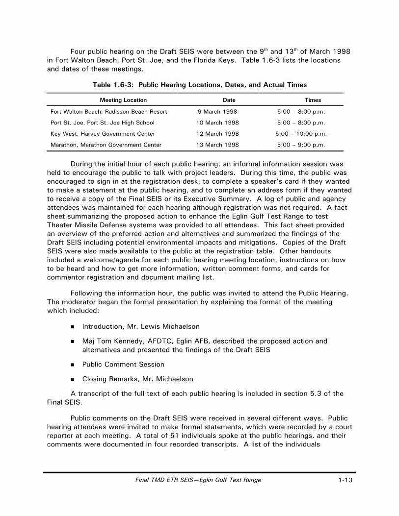
Four public hearing on the Draft SEIS were between the 9th and 13th of March 1998 in Fort Walton Beach, Port St. Joe, and the Florida Keys. Table 1.6-3 lists the locations and dates of these meetings.
Table 1.6-3: Public Hearing Locations, Dates, and Actual Times
Meeting Location Date Times
Fort Walton Beach, Radisson Beach Resort 9 March 1998 5:00 – 8:00 p.m.
Port St. Joe, Port St. Joe High School 10 March 1998 5:00 – 8:00 p.m.
Key West, Harvey Government Center 12 March 1998 5:00 – 10:00 p.m.
Marathon, Marathon Government Center 13 March 1998 5:00 – 9:00 p.m.
During the initial hour of each public hearing, an informal information session was held to encourage the public to talk with project leaders. During this time, the public was encouraged to sign in at the registration desk, to complete a speaker’s card if they wanted to make a statement at the public hearing, and to complete an address form if they wanted to receive a copy of the Final SEIS or its Executive Summary. A log of public and agency attendees was maintained for each hearing although registration was not required. A fact sheet summarizing the proposed action to enhance the Eglin Gulf Test Range to test Theater Missile Defense systems was provided to all attendees. This fact sheet provided an overview of the preferred action and alternatives and summarized the findings of the Draft SEIS including potential environmental impacts and mitigations. Copies of the Draft SEIS were also made available to the public at the registration table. Other handouts included a welcome/agenda for each public hearing meeting location, instructions on how to be heard and how to get more information, written comment forms, and cards for commentor registration and document mailing list.
Following the information hour, the public was invited to attend the Public Hearing. The moderator began the formal presentation by explaining the format of the meeting which included:
Introduction, Mr. Lewis Michaelson
Maj Tom Kennedy, AFDTC, Eglin AFB, described the proposed action and alternatives and presented the findings of the Draft SEIS
Public Comment Session
Closing Remarks, Mr. Michaelson
A transcript of the full text of each public hearing is included in section 5.3 of the Final SEIS.
Public comments on the Draft SEIS were received in several different ways. Public hearing attendees were invited to make formal statements, which were recorded by a court reporter at each meeting. A total of 51 individuals spoke at the public hearings, and their comments were documented in four recorded transcripts. A list of the individuals
Final TMD ETR SEIS—Eglin Gulf Test Range 1-13

who spoke at the public hearings, designated PT-0001 through PT-0051, and copies of the transcripts, are included in section 5.3.1.
Written comments on the Draft SEIS were received in various formats over the course of the public comment period. Initially, some prepared information was submitted to the moderator by speakers during each public hearing. In addition, written comment forms which were made available during registration were either returned at the conclusion of the public hearings or forwarded by mail. Finally, some individuals and several Federal, state and local agencies submitted letters of comment. In these three forms, written comments were received from 69 individuals representing themselves or private and public organizations. A list of the individuals, including their organization or agency affiliation where applicable, and copies of their transmittals are included in section 5.1.1. Written comments are designated PW-0001 through PW-0069.
In addition to transcript and written comments, the public was encouraged to e-mail comments to a mailbox designated for receipt of public comments: [email protected]. Twelve e-mails were received during the public comment. A list of the individuals who sent e-mails, and copies of the documents received are included in section 5.2.1. E-mail documents are designated PE-0001 through PE-0012.
Every transcript, written letter/comment, and e-mail was reviewed as it was received. Each document was assigned a unique number and then was carefully reviewed to identify the environmental resource area and specific topic of individual comments and issues that were presented. Each of these identified issues was highlighted and numbered sequentially. For example, if the tenth speaker presented in a transcript document (PT-0010) provided comments on 7 separate topics, those comments were numbered PT-0010.01 through PT-0010.07. A summary of each comment, its environmental resource area and topic was then entered into a database by the given identification number. This database was then used to sort and categorize all comments to the Draft SEIS so that appropriate and consistent responses could be provided.
The process of responding to comments required reaching a thorough understanding of the issues being presented and then determining the appropriate action to be taken. In some cases, the comment was a declarative statement not requiring a direct response, but one that did need to be noted in the context of overall public review. Other comments identified corrections or new information that was directly included in the text of the Final SEIS.
The largest number of comments received posed questions about the methodologies, analyses, and conclusions for various environmental resource impacts and mitigations presented in the Draft EIS (table 1.6-2). For each of these comments, a specific response was prepared—occasionally requiring the acquisition of new data and the preparation of additional analyses. New information and analysis supporting or changing the conclusions of the Draft SEIS was incorporated into the text of the Final SEIS as well as in the response to comments section.
Chapter 5 of the Final SEIS presents reproductions of all the original documents that were received during the public hearing comment period and provides direct
1-14 Final TMD ETR SEIS—Eglin Gulf Test Range

responses to every issue included in those documents. The organization of chapter 5 provides a separate comment/response section for each of the three types of comment documents:
5.1 Written Comment Documents
5.1.1 Written Comments
5.1.2 Response to Written Comments
5.2 E-Mail Comment Documents
5.2.1 E-Mail Comments
5.2.2 Response to E-Mail Comments
5.3 Transcript Comment Documents
5.3.1 Transcript Comments
5.3.2 Response to Transcript Comments
The first table in each section provides a index of the names and assigned identification numbers of individuals that submitted comments on the Draft SEIS. To follow comments and responses for a specific individual, find their commentor number (e.g., PW-0042, PE-0003, PT-0021) in the appropriate document list; locate their document with sequentially numbered comments; and, use the comment numbers to identify corresponding responses in the response table.
All documents and comments that were received during the public review period for the Theater Missile Defense Extended Test Range Supplemental Environmental Impact Statement were treated equally regardless of the form or commentor. Each comment was carefully documented, thoroughly read and evaluated, and provided with a response. Volume 2 of the Final SEIS includes the public comments and prepared responses. The National Environmental Policy Act requires the analysis of all reasonable alternatives to the proposed action. In accordance with CEQ guidelines, this SEIS includes sufficient analysis to inform the public and decision makers of potential environmental impacts resulting from the preferred action and alternatives and to assist in the decision making process.
Final TMD ETR SEIS—Eglin Gulf Test Range 1-15

THIS PAGE INTENTIONALLY LEFT BLANK
1-16 Final TMD ETR SEIS—Eglin Gulf Test Range

2.0 Description of Alternatives Including the Proposed Action

Final TMD ETR SEIS—Eglin Gulf Test Range 2-1
2.0 DESCRIPTION OF ALTERNATIVES INCLUDING THE PROPOSED ACTION
This chapter describes the program elements (section 2.1), the proposed action and alternatives to the proposed action (section 2.2), and alternatives eliminated from further consideration (section 2.3). It also compares the environmental consequences of the proposed action and alternatives (section 2.4).
2.1 PROGRAM ELEMENTS
The TMD Extended Test Range proposed action is to enhance the capabilities of the EGTR to allow BMDO to conduct interceptor missile flight testing and training activities in support of TMD systems. The enhancement of the EGTR in the proposed action or alternatives consists of upgrading and/or adding facilities where needed, and an increase in mission, adding the testing, development, and training of Theater Missile Defense systems to the ongoing EGTR mission of training, testing, and development of weapons systems. There is no proposal to enlarge the boundaries of the EGTR. While neither the Navy nor other TMD systems are currently committed to using the EGTR, this SEIS will evaluate the impacts of typical testing and training activities anticipated for major TMD systems under development. The TMD testing and training activities would likely occur over a period of 10 years or more from the decision to proceed.
For the purpose of this document, a flight test or test event means either a target missile flight, an interceptor missile flight, or an intercept of a target missile. Some test events proposed for later in the program may require multiple target and/or interceptor missile flights to validate interceptor missile performance. TMD testing or training activities could include up to 24 target launches and up to 48 interceptor launches per year.
The preferred alternative includes target and interceptor launch and support activities at Eglin AFB sites at Santa Rosa Island and Cape San Blas; Air Drop or air-launch of target missiles; and possible Navy AEGIS ship interceptor launch. Other alternatives include target launch and support activities at locations in the Florida Keys (Cudjoe Key or Saddlebunch Keys), target missile launch from a sea-launch vessel, and interceptor launch from offshore platforms near Santa Rosa Island and Cape San Blas (table 2.1-1).
In order to satisfy TMD test criteria objectives, missile flight tests must include testing of target missiles representing threat missiles that have a range up to 1,100 kilometers (683.5 miles). Tests involving intercepts of target missiles would be conducted at a variety of altitudes, with missile intercepts occurring over the Gulf of Mexico approximately 10 to 250 kilometers (6.2 to 155.3 miles) in altitude. Most tests would include the launch of a target missile, tracking by range and interceptor missile sensors, launch of an interceptor missile, intercept, and debris impact into the Gulf of Mexico.

2-2 Final TMD ETR SEIS—Eglin Gulf Test Range
Table 2.1-1: Proposed Eglin Gulf Test Range Flight Preparation and Test Activities by Geographic Location
Location
Interceptor Missile Launch
Target Preparation
Target Missile Launch
Intercept Debris
Instrumentation
PREFERRED ALTERNATIVE
Eglin Air Force Base
Santa Rosa Island * X X *
Cape San Blas * X X *
Gulf of Mexico
Air Drop or Air-launch Aircraft X
Sensor Aircraft X
Sensor Ship X
MacDill Air Force Base X
Navy Ship X X
Eglin Gulf Test Range *
OTHER ALTERNATIVES CONSIDERED
Eglin Air Force Base
Offshore Platform X X
Florida Keys
Boca Chica Key X
Cudjoe Key X X X
Fleming Key X
Saddlebunch Keys X X X
Sugarloaf Key X
Gulf of Mexico
Sea-launch X X
Port (Gulf of Mexico)
Sensor Aircraft X
Sensor Ship X
Eglin Gulf Test Range *
* Denotes locations and activities previously analyzed in the Extended Test Range EIS
The enhancement of the EGTR would expand its current missile testing capability. Missile defense program offices, with a need to conduct mid-range interceptor missile flight testing, may consider using the EGTR. Each missile test or training program proposing to use the EGTR would be evaluated for how best to satisfy the program’s test requirements, how to fit the program within the safety planning of the range, and how the specific test program would impact the environment. The AFDTC may accept the program if the proposed test scenario(s) could be safely accomplished within the EGTR.
To illustrate representative test or training events that could occur at the EGTR as part of the proposed action and alternatives, several test examples have been described in section 2.1.4. These examples are meant to represent possible TMD flight tests that could be conducted in the EGTR. These examples are not meant to be inclusive or

Final TMD ETR SEIS—Eglin Gulf Test Range 2-3
exclusive of other testing or training possibilities. Test scenarios not meeting representative criteria would need to be evaluated for possible supplemental environmental analyses. The following examples are more fully described in section 2.1.4:
The first example (section 2.1.4.2) shows a target missile launched from an airplane over the Gulf of Mexico intercepted by an interceptor missile launched from Eglin AFB Site A-15 on Santa Rosa Island. The intercept would occur over the northern Gulf of Mexico within the EGTR.
The second example (section 2.1.4.3) shows a target missile launched from Eglin AFB Site D-3A on Cape San Blas and an interceptor missile launched from a Navy ship in the Gulf of Mexico. The intercept would occur over the east-central Gulf of Mexico within the EGTR.
The third example (section 2.1.4.4) shows a target missile launched from a land site in the Florida Keys (either Cudjoe Key or Saddlebunch Keys) and an interceptor missile launched from an offshore platform off Eglin AFB Site D-3A on Cape San Blas. The intercept would occur over the northern Gulf of Mexico within the EGTR. The land site in the Florida Keys and the offshore platforms are alternatives to the preferred alternative.
The fourth example (section 2.1.4.5) could be either a system integration test or a training mission. It would involve multiple intercepts of multiple targets, delivered from both an air-launch over the Gulf of Mexico and a sea-launch vessel in the Gulf of Mexico by multiple interceptor missiles delivered from land sites and offshore platform sites at Eglin AFB Sites A-15 and D-3A. The sea-launch vessel is another alternative to the preferred alternative.
2.1.1 THEATER MISSILE DEFENSE SYSTEMS
TMD systems include the interceptor systems and sensor systems. In order to fully satisfy TMD test objectives, missile flight tests must include testing against target missiles representing mid-range threat missiles (figure 1.3-1). Tests involving intercepts of target missiles would be conducted at a variety of altitudes, with missile intercepts occurring over the Gulf of Mexico (within the EGTR) at altitudes of 10 to 250 kilometers (6.3 to 155.3 miles). For reference purposes, a comparison of TMD missile systems is illustrated in figure 2.1.1-1.
2.1.1.1 Interceptor Missile Systems
Interceptor missile systems destroy threat missiles and/or reentry vehicles in flight. Interceptor missiles being considered for TMD testing include, but are not limited to: PATRIOT Advanced Capability (PAC)-2 and PAC-3; Standard Missile (SM) -2 Block IVA and SM-3; Theater High Altitude Area Defense (THAAD); Hawk system; and Medium Extended Air Defense System (MEADS). The PAC-2 is an interceptor currently in the inventory. The PAC-3 is a new, smaller, more capable missile that will be integrated into the PATRIOT system. For the purpose of analysis, the PAC-3 system will be used as representative of land-based interceptors and the SM-2 Block IVA as representative of ship-based interceptors. These interceptor missiles are summarized in table 2.1.1-1.

025egl
TMD MissileComparison
Figure 2.1.1-1
EXPLANATION
ATACMSPAATPACSMTHAADMft
=======
Army Tactical Missile SystemPATRIOT as a TargetPATRIOT Advanced CapabilityStandard MissileTheater High Altitude Area DefenseMeters Feet
0
5
10
15
Hu
ma
n
Ha
wk
SM
-3
ME
AD
S
SM
-2 B
loc
k IV
A
TH
AA
D
PA
C-3
5.2 M(17.1 ft)
PA
AT
PA
C-2
5.3 M(17.4 ft)
5.3 M(17.4 ft)
Meters
TMD Targets
Interceptors
6.2 M(20.3 ft)
6.5 M(21.4 ft)
6.6 M(21.5 ft)
5.0 M(16.4 ft)
5.0 M(16.4 ft)
1.8 M(6.0 ft)
Pe
ga
su
s
15.5 M(50.8 ft)
2 S
tag
e H
era
Bla
ck
Bra
nt
9
13.58 M(44.54 ft)
12.2 M(40.0 ft)
ST
OR
M II
13.28 M(43.56 ft)
La
nc
e
6.14 M(20.14 ft)
He
rme
s(A
TA
CM
S)
4.0 M(13.1 ft)
Source: U.S. Army Space and Strategic Defense Command, Test and Evaluation Office, 1995.
2-4
Final TMD ETR SEIS Eglin Gulf Test Range

Final TMD ETR SEIS—Eglin Gulf Test Range 2-5
Table 2.1.1-1: Interceptor Missile Data
Name Length in meters (feet)
Diameter in meters (feet)
Launch Weight in kilograms (pounds)
PAC-2 5.3 (17.4) 0.42 (1.36) 907 (2,000)
PAC-3 5.2 (17.1) 0.25 (0.82) 320 (706)
SM-2 Block IVA 6.5 (21.4) 0.35 (1.14) 1,481 (3,264)
SM-3 6.6 (21.5) 0.34 (1.13) 1,514 (3,300)
THAAD 6.2 (20.3) 0.30 (1.00) Classified
Hawk 5.0 (16.4) 0.23 (0.70) 627 (1,383)
MEADS 5.0 (16.4) 0.25 (0.82) 350 (772) Source: U.S. Army Space and Strategic Defense Command, 1995; Manlove, 1997; Nelson, 1997.
The environmental impacts associated with individual interceptor missile systems have been addressed in program-specific environmental documentation for many of the systems. These systems include the THAAD Environmental Assessment (EA) (U.S. Army Space and Strategic Defense Command, 1994b); the Extended Range Intercept Technology (ERINT) EA (U.S. Army Strategic Defense Command, 1991); the PATRIOT Life-Cycle EA (U.S. Department of the Army, 1990); the PAC-3 Life-Cycle EA (U.S. Army Space and Strategic Defense Command, 1996); and the STANDARD Missile EA (Naval Ordnance Missile Test Station, 1990).
2.1.1.1.1 Interceptor Systems
Interceptor missiles launched from ground sites, offshore platforms, or Navy ships would use single- and multi-stage solid-rocket motor (SRM) boosters. SRM propellants are composed primarily of three basic components: a fuel element, an oxidizer element, and a binder that holds the fuel and oxidizer together in solid form. The SRM propellant consistency is similar to a rubber shoe sole.
Interceptor missiles destroy threat missiles or target missiles in flight. The kill methods used by the interceptors may include lethality enhancers (these destroy the target by detonating near it) or kinetic kill vehicles (the interceptor missile itself destroys the target by colliding with it at high speed). A lethality enhancer can be deployed near the intercept to further increase the probability of a successful target intercept (U.S. Army Space and Strategic Defense Command, 1994a).
A brief description of each missile system is included in the following paragraphs.
PAC-2 Missile System
The PAC-2, referenced in table 2.1.1-1, is an advanced, surface-to-air, guided missile system. The PAC-2 is equipped with four movable fins mounted on the tail. This missile propulsion is furnished by a single-grain SRM. The main components include the radome, terminal guidance section, propulsion section, and the control section.
The PAC-2 missile was previously described and analyzed in the EA for the PATRIOT Missile System (White Sands Missile Range, 1995).
2-6 Final TMD ETR SEIS—Eglin Gulf Test Range
PAC-3 Missile System
The PAC-3 system represents a typical land-launched interceptor missile for environmental analysis purposes (figure 2.1.1-2).
The PAC-3 missile, summarized in table 2.1.1-1, uses an SRM, aerodynamic controls, and a guidance system to navigate to an intercept point. Its ground-based fire solution computer selects the intercept point before launch. Shortly before reaching the intercept point, the on-board radar would acquire the target, and the missile would maneuver to intercept the target.
Navy STANDARD Missile–2 Block IVA Interceptor
The SM-2 Block IVA, referenced in table 2.1.1-1, is an SM-2 Block IV missile modified to add an area TMD capability, primarily through the addition of an infrared (IR) seeker to its existing anti-aircraft warfare capability. As part of the highly integrated AEGIS Weapon System, the SM-2 Block IVA provides a rapid fire endoatmospheric intercept capability for multiple high speed, high threat target engagements.
The SM-2 (figure 2.1.1-3) is vertically launched, booster enhanced, fueled by solid propellant, thrust vectored (during boost), and tail controlled (during second stage). It is a surface-to-air missile operable only from ships equipped with the Navy’s AEGIS Weapon System and Vertical Launching System. The SM-2 variant (designated Block IVA) is depicted in figures 2.1.1-1 and 2.1.1-3.
Navy STANDARD Missile–3 Interceptor
The SM-3 is the first STANDARD missile built solely for the TMD mission. As the Navy Theater-Wide (NTW) interceptor, it will be capable of long-range exoatmospheric direct hit engagements in either the target’s ascent or descent phase. The SM-3 will be similar to the SM-2 in that it is also a ship-launched interceptor using an MK 72 first stage and an MK 104 second stage booster. The SM-3 has replaced the guidance section with a third stage rocket motor and is approximately 2.5 centimeters (1 inch) longer than the SM-2. (McCleave, 1997)
THAAD System
Although THAAD has no current plans to conduct TMD testing at the EGTR, this SEIS will analyze the action for completeness. The THAAD system, described in table 2.1.1-1, will be a complete, integrated weapon system consisting of missile, launcher, and instrumentation. The missile uses a single-stage SRM for boost and a thrust vector control system for attitude control during the boost phase. Seeker and radar data guide the THAAD missile to an intercept point. THAAD is a hit-to-kill interceptor and does not carry an explosive warhead.

Representative PATRIOT/PAC-3 Test Battery
Figure 2.1.1-2
012egl
PAC-3
Launching Stations
EngagementControl Station
ElectricalPower Plant
AntennaMast Group
PATRIOTRadar Station
Source: U.S. Army Space and Strategic Defense Command, 1996.
2-7
Final TMD ETR SEIS Eglin Gulf Test Range

015egl
AEGIS Weapon System
Figure 2.1.1-3
AEGIS Cruiser
STANDARD Missile
2-8
Final TMD ETR SEIS Eglin Gulf Test Range
Final TMD ETR SEIS—Eglin Gulf Test Range 2-9
Hawk System
The Hawk missile, referenced in table 2.1.1-1, is an anti-aircraft surface-to-air missile (SAM). The missile is a single-stage cruciform configuration type with a dual thrust Aerojet M112 SRM. Flight control is achieved with elevons located on the trailing edges of the rear fins. (U.S. Marine Corps, Headquarters, 1995). An operational Hawk SAM has a warhead of 54 kilograms (119 pounds). The Hawk is launched from a mobile, trailer-mounted, triple-round launcher.
MEADS System
MEADS, described in table 2.1.1-1, will be an inertially guided, solid-propellant missile launched from a multiple launch rocket system launcher. The interceptor will be capable of carrying a variety of payloads which can be chosen according to a specific mission. The proposed action would involve the use of only inert payloads.
2.1.1.1.2 Representative Interceptor Missile System Components
PAC-3 System
A representative PATRIOT defensive missile ground-based launch site is illustrated in figure 2.1.1-2. The components of a typical PATRIOT fire unit include the engagement control station, launching stations, PATRIOT radar station, the antenna mast group, and the electrical power plant. The PAC-3 is representative of potential interceptor systems.
The engagement control station is the control center of the PATRIOT fire unit and contains the fire solution computer, weapon control computer, and various data and communications terminals. The launching stations, which are controlled by the engagement control station, are fully self-contained units that provide their own electrical power. Each launching station would carry up to 4 four-pack canisters of PAC-3 missiles for a maximum capacity of 16 PAC-3 missiles per launching station. Electrical power is provided by the electrical power plant which operates throughout the launch mission.
The PATRIOT radar station consists of an AN/MPQ-53 multifunction, phased array radar. The radar provides targeting and tracking information to the engagement control station throughout the missile flight test.
The antenna mast group consists of four antennas mounted in two pairs which can be elevated to heights up to approximately 33.5 meters (110 feet) above ground level.
The electrical power plant consists of two diesel-fueled, 150-kW, 400-hertz turbine engine generators. During test and evaluation, commercial power would be used with the generator serving as backup.
AEGIS Weapon System
The AEGIS Weapon System is an integrated, ship-based defense system consisting of a multi-function radar; a missile vertical launching system; interceptors; and support

2-10 Final TMD ETR SEIS—Eglin Gulf Test Range
command, decision, and display systems that translate weapon engagement orders into combat system commands. The AEGIS Weapon System supports STANDARD missiles, TOMAHAWK missiles, and anti-submarine rockets.
2.1.1.2 Interceptor Systems Transportation, Handling, and Facilities Requirements
2.1.1.2.1 Representative Ground-based Interceptor Launch Requirements
Interceptor missile boosters, payloads, and support equipment would be transported by air, ship, rail, or over-the-road common carrier truck from Government storage depots or contractor facilities to the test range. There they would be placed in secure storage until assembly and launch preparation. Applicable safety regulations will be followed in the transport and handling of hazardous materials. Range Safety would establish an appropriate explosive safety quantity-distance (ESQD) around facilities where ordnance is stored or handled in accordance with all applicable Federal, state, local, and installation regulations.
Interceptor missile launch preparation at ground-based launch sites would include the following activities:
Transportation, handling, and storage of interceptor missile system components and assemblies
Assembly and maintenance of interceptor missile system and support equipment
Checkout and testing of interceptor missile system components and assemblies
Maximum use would be made of existing infrastructure and facilities at ground-based launch sites. Existing facilities would be modified as necessary to support interceptor missile system operations. Additional infrastructure requirements may include on-site road improvements, fencing, electrical service, potable water, and telephone and data transmission lines.
Portable equipment used to support interceptor missile testing may include launchers, launch control stations, telemetry vans, personnel trailers, and power generators. A maximum of approximately 110 personnel (contractor, military, and Government civilian) may be required on-site for a period of up to 2 weeks to support an interceptor missile launch.
2.1.1.2.2 Representative Offshore-platform Launch Requirements
One of the alternatives for interceptor test and training activities in the EGTR would be to launch from new offshore platforms installed near Eglin AFB Site A-15 on Santa Rosa Island and/or near Site D-3A at Cape San Blas (figure 2.1.1-4). The platforms would allow Eglin Safety personnel to establish larger safety clear zones around the interceptors than land locations could accommodate. Target missiles could not be launched from sea-based platforms due to considerations in the Treaty on the Reduction and Limitation of Strategic Arms (START). The platform would be located between 8 and 20.9 kilometers (5 to 13

Figure 2.1.1-4
Sea Floor
30.5 Meters(100 Feet)
001egl
Representative Offshore Launch Platform-AlternativeInterceptor LaunchMode
Ap
pro
xim
ate
ly2
0 M
ete
rs(6
5 F
ee
t)
Ap
pro
xim
ate
ly3
0 M
ete
rs(9
8 F
ee
t)
Not to Scale
2-11Final TMD ETR SEIS Eglin Gulf Test Range

2-12 Final TMD ETR SEIS—Eglin Gulf Test Range
miles) offshore. It would be approximately 30.5 by 30.5 meters (100 by 100 feet) and 20 meters (65 feet) above the water line. For both sites, the water depth at this distance from shore is approximately 30.5 meters (100 feet). Piers sitting on the bottom would be permanent. Construction material would be either concrete or steel. Sensors would be mounted on the platform and hydrophones underwater to collect aircraft or missile positioning data during test or training events. Data would be transmitted to shore by underwater cable or microwave.
Platform installation operations usually involve the use of barges, crew boats, supply boats, tug boats, helicopters, and the platform itself. Platforms are generally fabricated at onshore platform fabrication yards and transported to the offshore site by barge for installation. Platform jackets are launched from a launch barge and lowered to the ocean bottom by controlled flooding. Steel pilings are driven to the desired depth through the jacket legs. The platform is leveled, grouted, and welded in place to each of the pilings. Platform raising generally requires a few weeks. The total site installation time is about 6 months.
Boats or helicopters would carry personnel and equipment to the platform for installation, checkout, and calibration prior to an event. The platform would not likely be manned during a test event. Interceptors could be launched remotely.
2.1.1.2.3 AEGIS Weapons System Launch Requirements
The AEGIS Weapons System is supported from various naval bases and would not require additional facilities for TMD testing and training activities.
2.1.2 TEST RANGE SUPPORT
2.1.2.1 Target Systems
The purpose of target systems in TMD testing is to provide realistic targets for testing new and evolving TMD interceptor missile and sensor systems. Targets are used to validate the capabilities of TMD interceptor systems. Targets must realistically simulate the expected threat, both in physical size and performance characteristics. Target missiles may be launched from fixed land locations, sea-launch vessels, or aircraft.
A typical TMD target missile consists of a booster (launch vehicle) and a target reentry vehicle (including payload, guidance and control electronics, and aerodynamic shell). The target missile would deliver the target reentry vehicle in a variety of configurations. A booster may consist of one or more stages. A stage refers to the number of times the vehicle is propelled by another booster. Multiple stages allow the missile to fly to higher altitudes and longer distances. Representative target systems are described in the following sections and in table 2.1.2-1. These are meant to represent a class or range of targets.

Final TMD ETR SEIS—Eglin Gulf Test Range 2-13
Table 2.1.2-1: Target Booster Data
Name Length in meters (feet)
Diameter in meters (feet)
Launch Weight in kilograms (pounds)
Pegasus (Total) 15.5 (50.8) 1.27 (4.2) 19,000 (41,895)
Pegasus First Stage 9.4 (30.8) 1.27 (4.2) 14,020 (30,914)
Pegasus Second Stage 2.3 (7.6) 1.27 (4.2) 3,400 (7,497)
Pegasus Third Stage 1.5 (4.8) 0.97 (3.2) 984 (2,170)
Hera (Total) 13.58 (44.54) 1.0 (3.28) 11,877 (26,188)
Hera First Stage (SR19-AJ-1) 4.32 (14.2) 1.32 (4.3) 7,201 (15,879)
Hera Second Stage (M57A-1) 3.36 (11.1) 0.95 (3.1) 2,305 (5,083)
Black Brant 9 (Total) 12.2 (40.0) 0.44 (1.4) 2,141 (4,721)
Black Brant 9 First Stage 4.27 (14.0) 0.46 (1.5) 878 (1,936)
Black Brant 9 Second Stage 5.71 (18.7) 0.44 (1.4) 1,272 (2,804.8)
STORM II (Total) 13.28 (43.56) 1.0 (3.28) 7,048 (15,541)
STORM II First Stage (Sergeant) 4.98 (16.34) 0.79 (2.58) 3,134 (6,910.5)
STORM II Second Stage (M57A-1) 2.18 (7.2) 0.96 (3.1) 1,967 (4,337.2)
Lance 6.14 (20.14) 0.56 (1.8) 1,527 (3,367.04)
PAAT 5.3 (17.4) 0.42 (1.36) 909 (2,003)
HERMES 4.0 (13.1) 0.61 (2) 1,670 (3,681.7)
Source: Chemical Propulsion Information Agency, 1994; U.S. Army Space and Strategic Defense Command, 1995.
2.1.2.1.1 Target Missiles
Pegasus
The Pegasus target missile, outlined in table 2.1.2-1, has three solid propellant stages. The principal advantage of this air-launch capable missile is its launch platform and rapid deployability (within 72 hours of call-up).
Hera
The Hera target missile, described in table 2.1.2-1, consists of two boosters or SRMs and a target reentry vehicle that represents an enemy warhead. The reentry vehicles vary in configuration and mass to replicate threat reentry vehicles. Typical masses range from 748.4 kilograms (1,650 pounds) to 884.5 kilograms (1,950 pounds). The Hera first-stage booster is a refurbished, stockpiled Minuteman II second stage (SR19-AJ-1) booster. The Hera second-stage booster is a refurbished Minuteman II, third stage (M-57A-1) booster. The propellant primarily consists of ammonium perchlorate, polybutadiene, and aluminum. Major exhaust products are carbon monoxide, water hydrogen chloride, nitrogen dioxide, and aluminum oxide.

2-14 Final TMD ETR SEIS—Eglin Gulf Test Range
The missile components would be built in other locations throughout the country and shipped to the launch site. The missile would be assembled by contractor personnel in the missile assembly building (MAB) using these components.
All SRMs under consideration are motors that were originally developed for other DOD missile programs. Many are existing surplus and are currently stored at existing DOD bases and depot facilities in the United States. Some target missile components (such as target reentry vehicles, fairings, and interstage adapters) were developed and fabricated specifically for the Hera target systems program. The Hera target systems EA addressed the activities associated with the manufacture, testing, and demonstration test flights of the Hera target systems (U.S. Army Space and Strategic Defense Command, 1994c).
The Air Drop target vehicle uses only the Minuteman II second stage booster. Otherwise, it is similar to a Hera, although a different name might be used depending upon the contractor involved.
Black Brant 9
The Black Brant 9, summarized in table 2.1.2-1, is a rail-launched SRM sounding rocket that may be used as a target. The missile is unguided, but it may be stabilized by optional canards on the nose cone. Typical mission range is 150 kilometers (93.2 miles).
STORM
The STORM booster system is one of the general-purpose Theater Ballistic Missile (TBM) target systems and is described in table 2.1.2-1. It has two boosters: a Sergeant first stage booster and a Minuteman I third stage as its second stage.
Lance Missile
The Lance, listed in table 2.1.2-1, is a U.S. Army field artillery system consisting of the missile, a self-propelled launcher, a loader-transporter vehicle, and ancillary equipment. The major sections of the missile are the main missile assembly (MMA) and the target reentry vehicle (figure 2.1.1-1). The MMA and the target reentry vehicle are stored and shipped in separate containers. Subsystems of the MMA include the propulsion system (a feed system and engine system) and the guidance system. The Lance's propulsion system consists of a prepackaged liquid propellant that includes an inhibited red fuming nitric acid oxidizer (IRFNA) (511 kilograms [1,126.76 pounds]) and unsymmetrical dimethylhydrazine fuel (UDMH) (150 kilograms [330.75 pounds]). The major exhaust products are carbon monoxide, carbon dioxide, water, and nitrogen.
PATRIOT as a Target
The PATRIOT as a Target (PAAT) is a fully operational PAC-2 missile (see figure 2.1.1-1 and table 2.1.2-1). To test PAC-3 missile system capability against short-range TBMs, a PATRIOT missile may be used as a target.

Final TMD ETR SEIS—Eglin Gulf Test Range 2-15
HERMES
The HERMES Target System is a variant of the Army Tactical Missile System (ATACMS) and is currently in the development stage. The HERMES is a short-range, solid-propellant, inertially guided missile (see figure 2.1.1-1). The HERMES is described in table 2.1.2-1. It has guidance, payload, propulsion, and aerodynamic control sections including four folding, swept, rectangular, clipped fins. Together, they form the airframe of the missile. It uses a rocket launcher mounted on top of a tracked vehicle (White Sands Missile Range, 1988; JANE’s Strategic Weapons Systems, 1995).
Development of the ATACMS and flight testing at WSMR began around 1985; it entered service early in 1991 for use in the Gulf War (JANE’s Strategic Weapons Systems, 1995). ATACMS was developed as a ground-launched missile system capable of destroying selected high-value targets while remaining outside the area of target threat. The HERMES has been proposed as an alternative for use as a target missile (White Sands Missile Range, 1988).
2.1.2.1.2 Target Missile Launch Modes
Land-launched Target
Land-launches of target missiles would be accomplished from a fixed launch pad. Missiles would be assembled on-site in a MAB, checked out in a movable environmental shelter, and erected on a launch stool on the pad prior to a scheduled launch. Each facility in which a missile is stored or processed would have an ESQD zone established around it. Prior to launch, a launch hazard area (LHA) would be established to ensure personnel are not exposed to missile launch hazards.
Short-range Air Drop Target
The short-range Air Drop Target System would provide an air-launch target delivery system using standard cargo aircraft and would provide a highly flexible short-range target system. This would allow multiple target test flights (figure 2.1.2-1). A programmatic EA of Air Drop targets is currently being prepared. A Description of Proposed Action and Alternatives for the Target Air Drop System is included in appendix D.
The Air Drop target missile currently being considered would be similar to the Hera (figure 2.1.1-1). It would consist only of an SR19 first stage, a Minuteman II interstage coupling, and target reentry vehicle. The interstage coupling provides a transition from the 132-centimeter (52-inch) diameter SR19 to the 97-centimeter (38-inch) diameter guidance control system. The interstage also provides for mounting and separation of the parachute system and incorporation of the flight termination system (FTS). Current treaty interpretations limit air delivery of targets to less than 600 kilometers (372.8 miles) from the predicted impact point if no intercept occurs.
The short-range Air Drop target system would provide a realistic simulation for testing TMD systems. An integrated target/pallet assembly would be loaded into a C-130 aircraft and flown to a predetermined drop point. At about 4,572 meters (15,000 feet)

Figure 2.1.2-1
Short-Range Air Drop Concept-Proposed TargetLaunch Mode
Test vehicle extraction fromaircraft at 4,572 meters (15,000 feet) MSL
1
2
3
4
5
Test vehicle separationfrom pallet Extraction
parachute
Stowed mainparachutes
Pallet descent onextraction parachute
007egl
Mainparachute
Missile descenton parachutes
Parachute separationfrom target launch vehicleat 1,524 meters (5,000 feet) altitude
2-16
Final TMD ETR SEIS Eglin Gulf Test Range

Final TMD ETR SEIS—Eglin Gulf Test Range 2-17
above mean sea level, an extraction parachute would pull the Air Drop assembly from the rear door of the aircraft. Soon after release, the target missile and sled would separate from the pallet, and the pallet would descend with its extraction parachute to the ocean. Two main parachutes would be released from packs on the sled assembly. When the target system reaches approximately 1,524 meters (5,000 feet) above mean sea level, the main parachutes would separate from the target missile and would descend to the ocean. The launch vehicle would then ignite and follow the predetermined trajectory to the intercept point.
As in tests using ground-launched target missiles, test plans using Air Drop targets will also identify hazard areas for the defensive missiles used in the test and for the debris from the planned intercepts. Air Drop target launch trajectories extend to a maximum range of 600 kilometers (360 miles). As an example of a representative mission, an Air Drop target might be flown on a launch point-to-aim point flight path of 320 kilometers (200 miles), with a maximum altitude of 220 kilometers (140 miles) and with a total flight time of approximately 8 minutes, 20 seconds. Re-entry velocity would be approximately 1.7 kilometers per second (3,800 miles per hour), with a re-entry flight path angle of -63.5 degrees (angle with the Earth’s surface).
A LHA, a target debris zone, and a booster drop zone would be designated for the target flight and intercept. These hazard areas would be cleared during a test to control access and reduce the potential risk of falling debris. Range clearance and access control would be in accordance with existing range procedures.
The Air Drop LHA would be designed to contain all Air Drop debris in the event it is destroyed before 40 seconds of flight. The parachute and pallet drop zones would be within the LHA.
Long-range Air-launch Target
BMDO has started development of an air-launch target to represent threat missiles with mid- to long-range capability. The Pegasus is being used as a representative long-range, air-launched target for purposes of environmental analysis. The Pegasus can be deployed from a cargo aircraft. The wing design of the Pegasus allows for lift after the missile is released from the aircraft, which complies with current treaty interpretations.
Mobile Sea-launched Target
Sea-launches of a number of different target missiles (such as the single stage Hera, PAAT, or HERMES) could be accomplished using a towed ship as a sea-launch vessel (figure 2.1.2-2). The candidate ship would be towed to appropriate launch locations in order to support the launch of the target missile.
In order to comply with the START Treaty, sea-launch targets would have to be launched no more than 600 kilometers (372.8 miles) from the predicted impact point.

Figure 2.1.2-2
Representative MobileSea-launch Vessel-Alternative TargetLaunch Mode
Missile buildup areawith overhead crane
Dismounted launch operationstrailers and telemetry station
Boosterstorage area
Crewquarters
Vehicle onerector launcher Retracted missile
environmental shelter
DimensionsSpeed Displacement
---
183.6 x 31.7 x 9.7 meters (602.3 x 104.0 x 31.7 feet)9.3 kilometers per hour (5 knots) (towed)9,978,980-17,077,663 kilograms (11,000-18,825 tons)
005aegl
2-18
Final TMD ETR SEIS Eglin Gulf Test Range
Final TMD ETR SEIS—Eglin Gulf Test Range 2-19
2.1.2.1.3 Target Reentry Vehicles
The target reentry vehicle is the portion of the target missile that is designed to represent threat warheads, or reentry vehicles. Typical target reentry vehicles may weigh up to 884.5 kilograms (1,950 pounds). In most cases the target reentry vehicle would separate from the booster prior to intercept. Target reentry vehicles typically consist of a steel housing assembly, optical sensors, guidance and control electronics, radio transmitters and receivers, a power supply (may include lithium or nickel-cadmium batteries), and a payload section for munition simulants, packaged either in bulk or submunitions. No live explosives are contained in the target reentry vehicles for test purposes. Some target reentry vehicles would also be equipped with stabilizer fins and cold-gas (nitrogen) thrusters to control roll, pitch, and yaw during final flight.
In the event of a missed intercept, the munition simulant in the target reentry vehicle may be dispersed to reduce the concentration of the simulant before it reaches ground or sea level. This would be accomplished through the detonation of a linear-shaped charge in the payload section. This system is independent of the FTS.
The purpose of using munition simulants in TMD target reentry vehicles is to assess the effectiveness of TMD interceptor missiles against threat missiles carrying chemical and biological agents as payloads. In order to adequately simulate this threat in testing, it is necessary to use materials which closely represent the physical characteristics of actual chemical and biological agents but do not have the toxic effects. Therefore, generally harmless simulants designed to represent the dispersion and other characteristics are used.
A typical chemical simulant that would be carried in target reentry vehicles in bulk would be triethyl phosphate. This compound is a colorless liquid with a mild odor. Triethyl phosphate has been approved for use in food packaging and is not regulated by the Occupational Safety and Health Administration (OSHA). Each target reentry vehicle would contain up to 132.5 liters (35 gallons) of the simulant when used. Submunitions, if used, would most likely contain water. Specific descriptions and a more detailed analysis of the properties of triethyl phosphate are discussed in the TMD Lethality Program EA (U.S. Army Space and Strategic Defense Command, 1993) and in a triethyl phosphate fact sheet included in appendix H.
Biological simulants are not proposed for use in the target reentry vehicles.
Penetration aids (penaids) may be used by the target systems to test the capability of the target reentry vehicles to penetrate missile defenses and reach their designated targets. Penaids accomplish this by overwhelming the defensive sensor and command and control systems with a large number of apparent warheads and by confusing the defensive systems as to the number and location of incoming warheads. Penaids could be housed in the target reentry vehicle separation module. One penaid technique is for an offensive missile to carry, in addition to the actual target reentry vehicle, several decoy target vehicles. These decoys, when released, appear to be actual warheads. These penaids would primarily be fabricated from graphite, stainless steel, and tungsten. In addition to decoys, chaff and radar (active and passive) may be used to test defensive sensor and command and control systems.

2-20 Final TMD ETR SEIS—Eglin Gulf Test Range
2.1.2.2 Target Systems Transportation, Handling, and Facilities Requirements
2.1.2.2.1 Ground-based Target Transportation, Handling, and Facilities Requirements
Target missile components and support equipment would be transported by air or over-the-road common carrier trucks from Government storage depots or contractor facilities to the MAB. There the missile components would be assembled for launch. Applicable safety regulations would be followed in the transport and handling of hazardous materials. An appropriate ESQD would be established and maintained around facilities where ordnance is stored or handled.
Target missile launch preparation at ground launch sites may include the following activities:
Construction and/or modification of facilities and infrastructure to support launch preparation and flight test activities
Transportation, handling, and storage of target missile system components and assemblies
Assembly and maintenance of target missile and support equipment
Checkout and testing of target missile system components and assemblies
Maximum use would be made of existing facilities and infrastructure at ground-based launch sites. Existing facilities would be modified and new facilities constructed only as necessary to support target missile system operations.
Potential facility requirements to support a Hera target at target system launch sites are summarized in table 2.1.2-2 and described in the following paragraphs. Additional infrastructure requirements may include site road improvements, fencing, electrical service, potable water, and telephone and data transmission lines.
Launch Pad
The launch pad and surrounding apron would be made of steel-reinforced concrete. It would support the launch stool and other equipment required to launch the target missile.
Launch Equipment Building
The launch equipment building would be a reinforced concrete structure located adjacent to the launch pad. It would have a 2.4-meter (8-foot) ceiling and would be 23.8 square meters (256 square feet).

Final TMD ETR SEIS—Eglin Gulf Test Range 2-21
Table 2.1.2-2: Facility Requirements, Land-launch Target
Facility Quantity Characteristics
Missile Assembly Building 1 512.8 square meters (5,520 square feet)
Launch Equipment Building 1 23.8 square meters (256 square feet)
Launch Pad 1 371.6 square meters (4,000 square feet)
Launch Stool 1 Bolted to launch pad (1.5 meters [5 feet])
RDAS Instrumentation site 2 Antennas mounted 1.5 meters (5 feet) above ground
Radar Site 2 Two vans on existing surface
Telemetry Site 1 One van on existing surface
Optics Site 2 Two vans on existing surface
Launch Operations Trailers Shelter 1 306.6 square meters (3,300 square feet)
Environmental Shelter 1 270.3 square meters (2,910 square feet) Clamshell Design
Security Facilities – Fence 2.4 meters (8 feet) high, enclosing missile assembly building, with security patrols
RDAS = Real-time data acquisition system Source: U.S. Army Space and Missile Defense Command, 1997.
Launch Operations Trailer Shelter
The launch operations trailer (LOT) shelter would contain tractor-pulled launch operations vans, which house communications and computer equipment. The LOT shelter would have a steel-reinforced concrete floor and walls (figure 2.1.2-3). The maximum height of the ceiling would be 4.9 meters (16 feet), and the entire building would be approximately 16.8 by 18.3 meters (55 by 60 feet). The LOT would house up to 10 essential personnel during launch activities.
Missile Assembly Building
The MAB would be a pre-engineered steel building with a concrete foundation and floor (figure 2.1.2-3). The interior would be finished with metal studs and gypsum board. This building would have a 10.7-meter (35-foot) minimum interior height and would be 18.3 by 28 meters (60 by 92 feet) in size, accommodating a minimum 18,144-kilogram (20-ton) overhead crane. Up to 10 essential personnel would work in the MAB.
Environmental Shelter
The environmental shelter, or clamshelter, would house the missile after it has been delivered to the launch pad, but before it is launched. It would be located on one end of the launch pad and cover the missile until it was raised into launch position. The clamshelter is a launch pad environmental enclosure complete with insulative liners and an explosion–proof electrical system. The clamshelter is mobile, with a steerable wheel system capable of a 360-degree turning radius and movement over undulating surfaces. It is designed to enclose the entire launch pad and vehicle, and does not require a rail system on the pad or roll-off area. The shelter measures approximately 29.6 meters (97 feet) long, 8.2 meters (27 feet) high, and 9.1 meters (30 feet) wide (figure 2.1.2-3). Its

009egl
Figure 2.1.2-3
Typical Launch SiteFacilities
Launch OperationsTrailer Shelter
Launch PadEnvironmental Shelter
Missile AssemblyBuilding
2-22
Final TMD ETR SEIS Eglin Gulf Test Range

Final TMD ETR SEIS—Eglin Gulf Test Range 2-23
length is approximately 13.4 meters (44 feet) when both clamshelter doors are retracted for maneuvering past the launcher. Total clamshelter weight is estimated at 5,443.2 kilograms (12,000 pounds).
The clamshelter is composed of vinyl-coated polyester supported on anodized aluminum arches and a steel box beam frame at the base. The insulated shelter can be maintained at 27 degrees Celsius (°C) (80 degrees Fahrenheit [°F]) with low relative humidity using a 9,072-kilogram (10-ton) capacity air conditioning unit (recirculated air).
Real-time Data Acquisition System Instrumentation Site
The Real-time Data Acquisition System (RDAS) consists of antennas mounted on four pre-surveyed poles, approximately 1.5 meters (5 feet) above ground level. Above ground wiring or a microwave link would connect the RDAS to the operations vans in the LOT shelter.
Radar Site
The radar sites would consist of a portable radar, technical van, and a climatic van which would be placed on site before the launch (figure 2.1.2-4). The radar equipment would be placed on site for approximately 1 week before each test.
Telemetry Site
The telemetry site would consist of one van with a communications dish which would be co-located with the radar site closest to the launch pad (figure 2.1.2-4). The telemetry equipment would be placed on site approximately 1 week before each test.
Optics Site
The optics sites would consist of four elements: telescope, fixed camera, control van, and controller van (figure 2.1.2-4). The optics equipment would be placed on site for approximately 1 week before each test.
Range Control Site
The range control site would consist of several telemetry, communications, meteorological, and other control functions housed in approximately seven tractor-pulled vans (figure 2.1.2-5). The range control vehicles and trailers would be placed on-site for approximately 2 weeks before each test.
Guardhouse
The guardhouse (if required) would be a reconstructed portable building which would control entry into the target launch area. It would be large enough for only one occupant. The building would have a 2.4-meter (8-foot) interior height and would be approximately 3.7 by 2.4 meters (12 by 8 feet) in size.

006egl
Figure 2.1.2-4
Representative Radar,Optics, and TelemetryEquipment
Telemetry Site
Radar Site
Optics Site
2-24
Final TMD ETR SEIS Eglin Gulf Test Range

013egl
Figure 2.1.2-5
Representative Range ControlSupport Equipment
Control Van
Communication Van
Flight TerminationSystem
2-25
Final TMD ETR SEIS Eglin Gulf Test Range

2-26 Final TMD ETR SEIS—Eglin Gulf Test Range
2.1.2.2.2 Air Delivery Target Transportation, Handling, and Facilities Requirements
The rocket motor would be shipped to the deployment location from the refurbishing contractor’s facility by truck or air. Other components, such as the ground control system, aft skirt and fins, and the sled-and-pallet assembly, would be shipped to the launch site from other contractor locations (as applicable). When the SRM and other components arrive at the launch location, the motor would be transferred to a missile or booster assembly building for installation of the FTS and integration of the other components. The target reentry vehicle would be attached to the pallet and sled equipment. Before deployment, the booster, pallet and sled assembly, and support equipment would be loaded onto the aircraft.
Applicable safety regulations will be followed in the transport and handling of hazardous materials. An appropriate ESQD would be established and maintained around facilities where ordnance is stored or handled.
Approximately 25 to 30 people would be involved in the transportation, handling, and checkout of the missile. The missile components would arrive approximately 3 weeks prior to launch. A roller dock assembly with a 11,340-kilogram (25,000-pound) capacity loader would be required to load the target on its pallet. Other handling and transfer equipment would include a crane, forklifts, and a 6.1-meter (20-foot) flatbed trailer equipped with transfer rails for the motor.
Eglin AFB would be able to accommodate air-launch or Air Drop of a target missile with the existing support facilities and infrastructure. Therefore, no construction or additional major equipment would be required.
2.1.2.2.3 Sea-launch Target Transportation, Handling, and Facilities Requirements
Sea-launches of target missiles may be conducted using specially configured target missiles and ships based at a port within support range of the test area having approved explosive handling capabilities. The sea-launched target would be obtained by modifying an existing Black Brant 9, Hera, Lance, or ATACMS (HERMES) target missile (U.S. Department of Defense, Ballistic Missile Defense Organization, 1995).
Target missiles and support equipment would be transported by over-the-road common carrier truck from Government storage depots or contractor facilities. They would be placed in secure storage until assembly and launch preparation. Applicable safety regulations would be followed in the transport and handling of hazardous materials. An appropriate ESQD would be established and maintained around facilities where ordnance is stored or handled.
Approximately 50 people would be involved in the transportation, handling, and checkout of the missile. The missile components would arrive approximately 3 weeks before launch.
A vessel to support the sea-launched target missile would be based at a port in the Gulf of Mexico within supporting range of the test area with appropriate explosive safety and handling capability. The vessel would be towed to the appropriate launch location.

Final TMD ETR SEIS—Eglin Gulf Test Range 2-27
The sea-launch vessel would accommodate needed range support systems such as communications relays (command and control), data collectors (telemetry), and tracking systems (infrared or optical). It would also provide a safe shelter for personnel engaged in the mission.
2.1.2.3 Test Range and Support Instrumentation
Sensor systems are used to acquire, record, and process data on targets and interceptor missiles in order to detect and track targets, direct defensive missiles, and assess whether a target has been destroyed. Sensor systems also include signal processing components.
The signal processing components receive the raw data collected by the sensor elements and process it, using computer hardware and software, into usable information such as target location, velocity, and attitude. These and other relevant characteristics can then be used to plan and control intercept engagements.
Sensor systems associated with interceptor missiles which may be used include existing ground-based sensors and newly developed or modified sensor systems. Some sensors planned for use would be standard, fixed, and portable units. These units are routinely used to support flight tests. Potentially, other airborne sensors, ship-based sensors, and space-based sensors may also be used for surveillance and tracking support as part of these proposed TMD missile tests.
Instrumentation associated with the launch of a target missile would include two radar sites, two optics sites, two telemetry sites, and a range control support equipment site. A typical radar site and optics site is shown in figure 2.1.2-4. Telemetry is provided through an RDAS as shown in figure 2.1.2-4. Range control support equipment would include seven semi-type vans for FTS, meteorological, transponder, control, communications, and timing systems. Examples are shown in figure 2.1.2-5. All of these systems are mobile and would be brought to the vicinity of the launch site approximately 1 to 2 weeks before the launch date. In most cases the equipment would be removed within days after the launch.
The U.S. Army Space and Missile Defense Command (USASMDC) is managing an effort to expand the capabilities of aircraft to provide airborne instrumentation at test locations for the BMDO. The Naval Air Warfare Center Weapons Division at Point Mugu, California, was tasked by USASMDC to develop and configure an aircraft as a remote area safety aircraft (RASA) for airborne missile range safety support (figure 2.1.2-6). This effort would provide two RASA-equipped aircraft, each capable of stand-alone support of missile tests.
Planned TMD operational tests may involve various test locations and include multiple launches and simultaneous target engagements. These tests would need supplementary support to existing instrumentation. In these instances, the RASA-equipped aircraft and its personnel would serve as an extension of the range safety assets and provide range safety support for the tests. One aircraft could be modified to provide stand-alone missile range safety support.

Figure 2.1.2-6
Representative Remote Area Safety Aircraft
016egl Coordinating Final TMD ETR SEIS Eglin Gulf Test Range
2-28

Final TMD ETR SEIS—Eglin Gulf Test Range 2-29
2.1.3 RANGE PLANNING AND OPERATIONS
The AFDTC, located at Eglin AFB, has been a weapons development test center for more than 50 years. In fiscal year (FY) 1995, Eglin AFB personnel supervised more than 10,000 weapons test or training missions on Eglin AFB ranges. Every mission is planned, scheduled, and conducted with safety as the primary consideration. Any mission that has the potential to do physical damage to items underneath it will require portions of one or more ranges to be cleared of personnel to ensure safety. Clearing land or overwater ranges of personnel during these missions is a standard part of supervising weapons testing or training. In 1995, Eglin AFB’s land ranges were cleared during more than 6,400 missions, and its overwater ranges were cleared during more than 4,200 missions. TMD missile testing and training would be a new mission on the EGTR, but the steps for planning and safely conducting this mission would be similar to ongoing operations, constituting less than 100 hours per year.
2.1.3.1 Range Planning
As a major DOD range, the AFDTC at Eglin AFB conducts test activities for a number of weapon system programs. The AFDTC is responsible for supporting the timely, effective conduct of a wide variety of test activities on the Eglin AFB land and overwater ranges. The existing programming process allows a program office to determine whether Eglin AFB can support their specific test requirements and allows Eglin AFB to determine if the range can accommodate those tests. It is called the Programming Process.
This SEIS will support the environmental impact analysis requirement for a class of TMD missile test flights in the EGTR, using a variety of launch modes and locations. The safety review part of the Programming Process evaluates whether the proposed test scenario fits within the safety parameters of the EGTR. A missile test program that does not meet the safety compliance requirements of the EGTR will not be accepted for testing at Eglin AFB.
2.1.3.2 Pre-test Planning and Operations
2.1.3.2.1 Launch Site Operations
The launch site, for target launches, would be occupied for approximately 4 weeks before a launch and 2 days after a launch. The site would be occupied 8 to 10 hours a day during assembly and check-out. The week before the launch, the launch site would be occupied by at least five people 24 hours a day. On the day of test there may be as many as 40 or 50 program-related personnel at the launch site or at mission control. After a successful test, approximately 50 personnel would immediately depart. The rest would depart within a week.
The launch site for interceptor launches would be occupied for approximately 2 weeks. The interceptor system and approximately 110 associated personnel would arrive 2 weeks prior to launch.

2-30 Final TMD ETR SEIS—Eglin Gulf Test Range
Interceptor and target missile contractor test personnel would be housed in motels or hotels in the vicinity and would commute to the launch site daily. Government and military test personnel may use military or commercial lodging.
2.1.3.2.2 Missile Transportation and Handling
Missile components would be built in locations throughout the country and delivered to the launch site by truck for system assembly and check-out. Missiles would not be shipped with initiators or other explosive devices. Missiles would be tested at the DOD depot activity or contractor’s facility before shipment. All missile components would be packaged in appropriately designed containers, labeled, and handled in accordance with applicable U.S. Department of Transportation (USDOT) regulations for the transport of hazardous materials. Some missile components may be shipped to a military airfield near the launch site and transferred to the launch site by local truck. Missile components would be handled by trained personnel using only appropriately certified cranes and handling equipment in accordance with approved Air Force standard operating procedures.
Interceptor missile launch batteries (personnel and equipment) are mobile and would be driven onto the proposed interceptor launch site and set up for the test or training approximately 2 weeks in advance. There would be little site preparation before an interceptor launch other than installing instrumentation and communications and ensuring security.
2.1.3.2.3 Safety Clearance Area Definition
When a missile flight test is planned, there are certain areas where missile components and debris are expected to impact. These are the “booster drop zone” and the “debris impact area.” These areas are cleared of personnel as part of the test plan. There are other areas where debris may land if the test does not proceed as planned. These predetermined areas of the test event may be subject to the risk of mishap, such as an explosion or flight termination. Clearance areas are defined by the Eglin AFB Range Safety Office to encompass the maximum probable distribution of debris or impact points of missile components.
Each missile flight test event would be modeled using computer predictions of the behavior of the missiles. This modeling predicts what the missile may do in a number of situations where the missile, or parts of the missile, may fall to earth. The models incorporate a number of variables such as the missile mass, velocity, trajectory, altitude, and descriptions of the environments that may affect the missile in flight such as surface and high altitude winds, precipitation, humidity, etc. Modeling that is done long ahead of the actual test would use average weather predictions. Modeling would be done on the day of test using actual conditions to verify the earlier predictions.
Specific clearance areas are defined for each flight test depending upon the profile of that test (figure 2.1.3-1). The profile includes such variables as the direction, altitude, size of missile, and speed and velocities of winds at all altitudes. These variables are all analyzed using computer models for each test mission to predict where the debris or missile components may land after an intercept or a miss. The modeling also predicts the location and probability of where debris may land in case of mishap or an unplanned event

egl009
Schematic TMDFlight Test ClearanceAreas
Figure 2.1.3-1Not to scale
Target Launch Hazard Area
First-stageBooster Drop Zone
Ground Projectionof Flight Path
Flight Corridor
Existing Rangeand Open Sea Area
Interceptor MissileImpact Zone(If No Intercept)
Interceptor MissileIntercept DebrisImpact Zone
Target InterceptDebris Impact Zone
Target Second-stageImpact Zone
Target ReentryVehicle ImpactZone (If No Intercept)
Interceptor MissileLaunch Hazard Area
EXPLANATION
Intercept
Clearance Areas
Flight Path
Flight Corridor Boundary
ESQD
Note: ESQD = Explosive Safety Quantity-distance
2-31
Final TMD ETR SEIS Eglin Gulf Test Range

2-32 Final TMD ETR SEIS—Eglin Gulf Test Range
(such as a flight termination). The Range Safety Office would communicate the extent of the clearance area, time, and date of the flight test, once they are defined, to the FAA, the Coast Guard, the Florida Marine Patrol (FMP), the Department's Division of Emergency Management, and local police jurisdictions for assistance in the clearance of designated land and sea-surface areas. Other areas under the flight path, but not in a predicted impact or debris area, would be monitored prior to the test event to determine the location of population or traffic. If the Range Safety Office determined that the population or ship traffic was in a safe position, the test would proceed.
Ground and range safety areas are developed to protect the public and private property against potential test mishaps. These safety areas are defined in terms of three scenarios: termination or explosion on the ground, either in the MAB or on the launcher; termination of a missile’s flight shortly after liftoff; and termination of a missile’s flight after it has left the vicinity of the launch site.
An Explosive Safety Quantity-Distance (ESQD) is based on the possibility of an explosion of a missile in the MAB or on the launch pad. It would be characterized by either an explosion of the missile propellants or propellants burning without an explosion. An ESQD zone surrounding the launch pad would be calculated in accordance with DOD Regulation 6055.9. The ESQD would be based on the equivalent explosive force of all propellant and pyrotechnic materials contained in the flight vehicle and the greatest distance such a force would propel debris. The ESQD zone would be cleared of non-mission-essential personnel for the period during which the explosives are in the facility. All hazardous debris resulting from a termination on the launch pad would be contained within the ESQD zone.
An ESQD is intended to ensure that explosives are not stored near inhabited structures or public roads. The ESQD for the class and amount of explosives to be used in TMD testing is a 289.6-meter (950-foot) radius to any inhabited buildings. Fire suppression, hazardous materials emergency response, and emergency medical teams during launch operations will be provided in accordance with the Draft Evacuation Plan and Draft Emergency Response Plan (appendices I and J).
Before BMDO would build a missile launch site, the Eglin AFB Range Safety Office would determine if the missiles could be safely launched from the proposed location. To do this, the Range Safety Officer develops a Launch Hazard Area (LHA) around the proposed launch site. The LHA is the area that could be affected by pieces of missile debris should an explosion occur on or just above the launch pad or in the event that the missile’s flight must be terminated in the early flight phase. This LHA is cleared of all but mission-essential test personnel during launch operations. The proposed LHAs for the alternative launch locations are displayed in figures 2.1.3-2 through 2.1.3-5. The description of the LHA development is found in more detail in the LHA Development Process description (appendix G).
Another type of range safety area is based on the possibility of a termination of a flight after the missile has exited the vicinity of the launch pad. A termination of this kind

Launch Hazard Area,Site A-15
Figure 2.1.3-2
Santa Rosa Island, Florida
sri-500k-2land001
Valparaiso
Hurlburt
Gulf of Mexico
Santa Rosa Island
EXPLANATION
Eglin Air Force Base Boundary
8 Miles
NORTH
0 4
0 13 Kilometers6.5
Roads
Scale 1:500,000
Crestview
Fred GannonRocky Bayou
State RecreationArea
Mary Esther
Cinco BayouFort Walton Beach
Shalimar
Destin
Freeport
Navarre
NavarreBeach
Site A-15
Site A-10
Niceville
De Funiak Springs
Launch Hazard Area
Launch Site
Florida
Index Map
Eglin Air Force Base
Choctawhatchee Bay
Municipalities
Source: U.S. Department of the Air Force, 1995.
2-33
Final TMD ETR SEIS Eglin Gulf Test Range
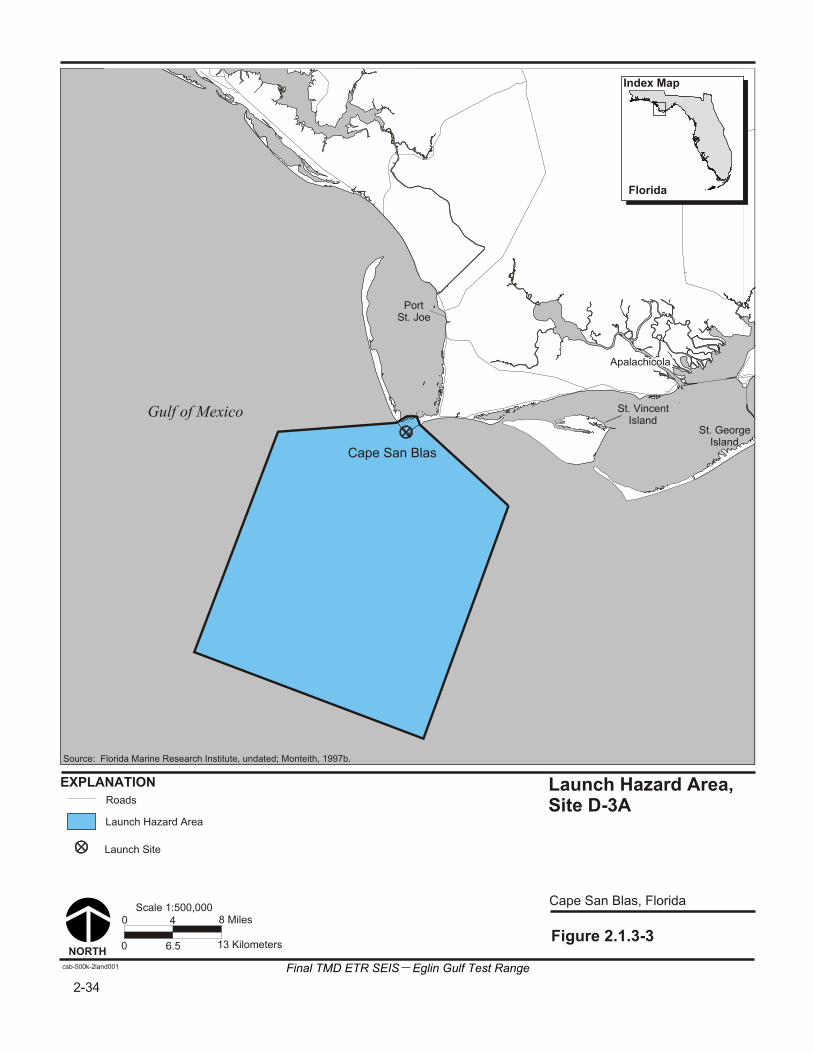
St. GeorgeIsland
Apalachicola
Cape San Blas
Gulf of Mexico
EXPLANATION
Figure 2.1.3-3
Cape San Blas, Florida
NORTH
8 Miles0 4
0 13 Kilometers6.5
Scale 1:500,000
csb-500k-2land001
Florida
Index Map
Launch Hazard Area,Site D-3A
St. VincentIsland
Roads
Launch Hazard Area
Launch Site
PortSt. Joe
2-34
Source: Florida Marine Research Institute, undated; Monteith, 1997b.
Final TMD ETR SEIS Eglin Gulf Test Range
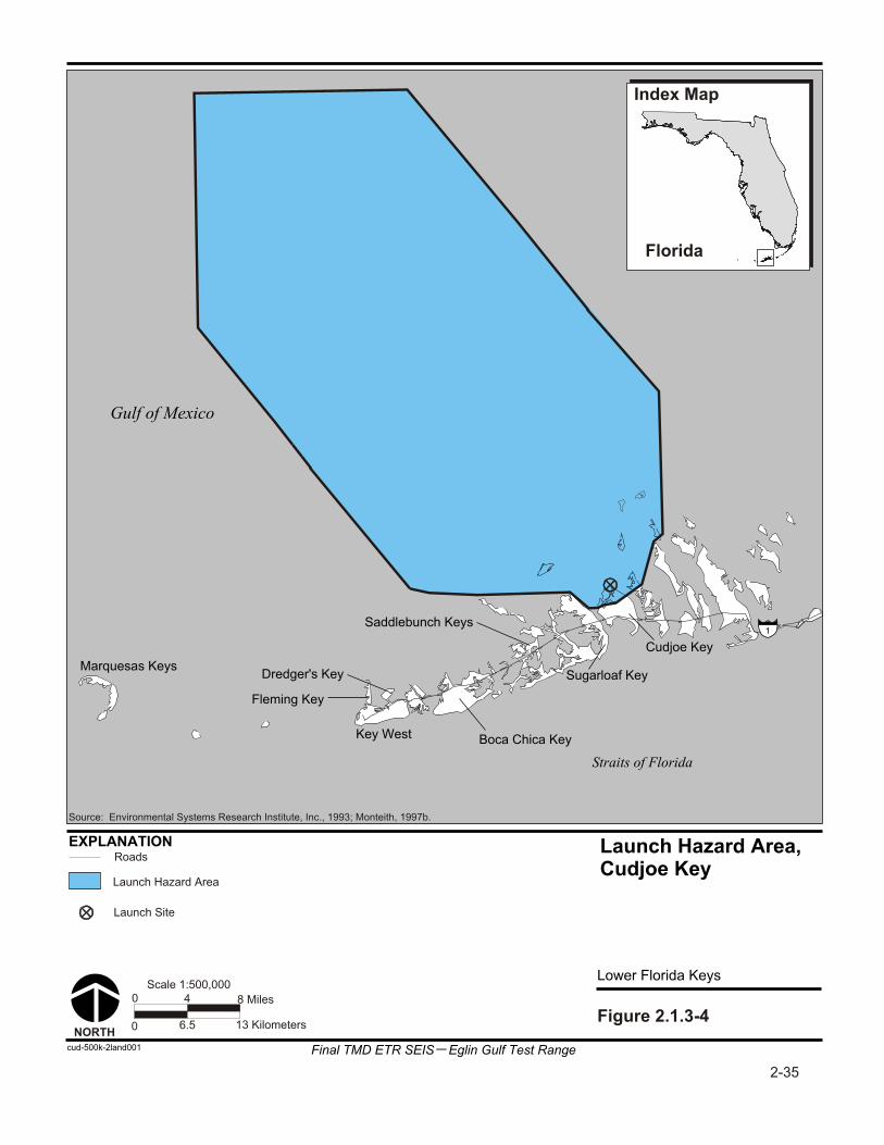
Lower Florida Keys
cud-500k-2land001
EXPLANATION
Straits of Florida
Gulf of Mexico
Marquesas Keys
Key West
Saddlebunch Keys
Dredger's Key
Boca Chica Key
Fleming Key
Sugarloaf Key
Cudjoe Key
Launch Hazard Area,Cudjoe Key
NORTHFigure 2.1.3-4
Florida
Index Map
8 Miles0 4
0 13 Kilometers6.5
Scale 1:500,000
1
Roads
Launch Site
Launch Hazard Area
2-35
Source: Environmental Systems Research Institute, Inc., 1993; Monteith, 1997b.
Final TMD ETR SEIS Eglin Gulf Test Range

Lower Florida Keys
key-500k-2land003
EXPLANATION
Straits of Florida
Gulf of Mexico
Marquesas Keys
Key West
Saddlebunch Keys
Dredger's Key
Boca Chica Key
Fleming Key
Sugarloaf Key
Cudjoe Key
Launch Hazard Area,Saddlebunch Keys
NORTHFigure 2.1.3-5
Florida
Index Map
8 Miles0 4
0 13 Kilometers6.5
Scale 1:500,000
1
Roads
Launch Site
Launch Hazard Area
2-36
Source: Environmental Systems Research Institute, Inc., 1993; Monteith, 1997b.
Final TMD ETR SEIS Eglin Gulf Test Range

Final TMD ETR SEIS—Eglin Gulf Test Range 2-37
would occur in the event of an off-course flight. Mission planning and procedures would ensure the FTS would be activated in time for the flight vehicle to fall within its predicted flight corridor in the event of an off-course flight.
Should the missile head off course such that it is leaving its predicted flight corridor, the Range Safety Officer would activate the FTS. This would stop the flight vehicle's thrust, and the missile would then fall ballistically into the sea. This impact could occur outside cleared areas in a predetermined flight corridor. The probability of human casualties or property damage would be extremely remote in the event of an impact within the flight corridor.
Land Areas
Land areas that would need to be cleared are the LHA for each missile. Land areas would be cleared in cooperation with appropriate local law enforcement officials. Land areas would need to be cleared approximately 1 hour before a launch. As soon as the Range Safety Officer determines that the area is safe, the LHA could be reoccupied.
Airspace
FAA-controlled airspace is that in which most commercial aviation operates; that is, airspace up to an altitude of 18,288 meters (60,000 feet). Military Special Use Airspace may extend to higher altitudes, depending upon the individual restricted or warning area. The missiles involved in these TMD flight tests rapidly climb through this airspace and follow trajectories high above the atmosphere. FAA-controlled airspace that would be affected includes airspace above the LHA for both the interceptor and the target launches, airspace above the booster drop zone, airspace above the predicted debris drop zone, and airspace above the predicted whole body miss landing point of each missile.
The airspace associated with the LHA would be a Controlled Firing Area (CFA). The distinguishing feature of a CFA, compared to other special use airspace, is that its activities are suspended immediately when spotter aircraft, radar, or ground lookouts indicate an aircraft may be approaching the area. Airspace associated with the booster drop zone or whole body miss impact point would likely be in an existing Warning Area over water.
Debris modeling for the day of test would predict the dispersion and linger time for test impact debris. Linger time is the time it would take for debris as small as 1 gram (0.04 ounce) to fall to earth given the weather conditions at the time. Such small debris is important because it could be ingested into aircraft engines in flight. This debris dispersion area may also have to be cleared of aircraft for some time after an intercept. Airspace would need to be cleared in advance of a planned test event to allow sufficient time to ensure that it is indeed clear; this would be approximately a half-hour before test launch. As soon as the Range Safety Officer determines that the area is safe, the airspace could be reoccupied. It could be as long as 2 to 4 hours before a debris dispersion area is declared clear.

2-38 Final TMD ETR SEIS—Eglin Gulf Test Range
Sea-surface Areas
Sea-surface areas that would have to be cleared include the LHA that extends overwater, the predicted booster drop zone, the predicted debris impact area, and the predicted whole body miss impact point for each missile. Sea-surface areas within the 22.2-kilometer (12-nautical-mile) limit would be cleared with the cooperation of the FMP and the Coast Guard. Sea-surface areas beyond the 22.2-kilometer (12-nautical-mile) limit would be cleared with the cooperation of the Coast Guard. Sea-surface areas would need to be cleared in advance of a planned test event to allow sufficient time to ensure that it is indeed clear; this would be approximately 4 hours before test launch. As soon as the Range Safety Officer determines that the area is safe, the sea-surface areas could be reoccupied.
2.1.3.2.4 Safety Clearance Area Procedures
Once a test or training event is scheduled, there would be a standard sequence of notification and coordination procedures between the Eglin AFB Range Safety Office and the agencies that would enforce the clearance of land, air, and sea areas. These are discussed below. Additional information is contained in the Draft Evacuation Plan (appendix I).
Land Areas
The date and location of scheduled flight tests or training events would be published 1 week in advance. Notice of intent to clear certain land areas for safety reasons would be published in local newspapers and broadcast in local news media. The boundaries of LHAs would be posted with notifications. For land owned by the military, the military police would close the area 1 hour before the planned launch and then patrol the area to ensure that it is clear of non-mission personnel. For non-Federal land adjacent to a launch site and within the LHA, an easement with private property owners would be in place prior to test activities for local law enforcement officials to have the legal authority to clear that land.
Airspace
The date and location of scheduled flight tests or training events would be published 1 week in advance. The FAA would publish a Notice to Airmen (NOTAM) to avoid certain airspace areas for safety reasons. Conditions that are expected to exist for an extended period of time are reported in a Flight Data Center (FDC) or Notice to Airmen Distance (NOTAM D) and are published in the next biweekly NOTAM publication. The boundaries of LHAs would be posted with notifications, and Air Force radar and aircraft would patrol the airspace to ensure that it is clear of aircraft before each flight test.
Sea-surface Areas
The date and location of scheduled flight tests or training events would be published 1 week in advance. The Coast Guard would publish a Notice to Mariners (NOTMAR) to clear certain sea-surface areas for safety reasons. Notice of intent to clear certain sea-surface areas for safety reasons would be published in local newspapers,

Final TMD ETR SEIS—Eglin Gulf Test Range 2-39
broadcast in local news media, and distributed to commercial fishing and tourist boating trade associations. Subject to the conditions of appropriate Memoranda of Agreement, Coast Guard and FMP officials would close the sea-surface area(s) up to 4 hours before the planned launch and then survey them to ensure that they are clear of ships or watercraft. Coast Guard boats and Air Force aircraft would patrol the area to ensure that it is clear of ships or watercraft.
2.1.3.3 Test Operations
2.1.3.3.1 Clearance Area Monitoring Procedures
One hour before a missile test flight or training event, an aerial surveillance aircraft would survey the proposed sea-surface and airspace clearance areas. Should any aircraft be found, the surveillance aircraft would contact the plane on the radio and request that it depart the area. Should any watercraft be found, the Coast Guard would escort the watercraft out of the clearance area.
2.1.3.3.2 Missile Launch
The AFDTC Test Engineer and the Range Safety Officer would control the flight test from the central control facility. They would follow standard operating procedures for missile launch countdown and would ensure test requirements are satisfied and range safety requirements are met. At appropriate stages in the countdown, the range control and test data collection sensors would be confirmed “available”; the land, air, and sea clearance areas would be confirmed “clear”; the interceptor system would be confirmed ready for launch; and the target system would be confirmed ready for launch.
Weather conditions over the entire range of the flight test would be confirmed and the model updated. All the variables that affect the missile’s performance would be monitored. Each variable (for example, high altitude winds) has limits that can not be exceeded without affecting the planned test profile. At the scheduled time, if all variables are within acceptable bounds, the test engineer would launch the target missile. The interceptor weapon control system would acquire and track the target missile. The interceptor would then be launched at the best intercept time.
A test flight may be delayed for a number of reasons. A launch could slip incrementally for as long as 4 hours. After 4 hours, the mission would be postponed and the clearance areas released. The mission would be rescheduled for another day with new clearance notices published for the new day. Normally, the maximum duration of clearance would be 4 hours. It is not anticipated that this 4-hour period would be required for most tests.
2.1.3.3.3 Missile Flight
Each missile in a flight test is tracked by a variety of sensor equipment to determine exactly where the missile is at all times during the flight. This tracking provides useful data to the program to satisfy test objectives as well as a range safety tool. The Range Safety Officer uses the real-time tracking capability, linked with the predictive modeling capability, to predict at any moment in the flight where the missile may land if thrust were

2-40 Final TMD ETR SEIS—Eglin Gulf Test Range
terminated at that moment. This prediction is called an instantaneous impact point (IIP). Should a missile veer from its predicted flight path, the IIP predicts where it would fall. If the missile is predicted to leave the flight corridor or clearance areas, the Range Safety Officer would terminate the flight.
2.1.3.3.4 Post Test Clearance Area Release
After completion of a missile flight test or training event, the clearance areas would be released, or allowed to be reentered. The Range Safety Officer would do this as soon as he or she was assured that any hazardous aspect of the test was completed. Such residual hazardous concerns may be gasses from missile exhaust, presence of hazardous debris, debris still falling after an intercept, or other potentially dangerous consequences. Notification would be by radio or telephone to aviation and maritime authorities.
2.1.3.3.5 Debris Recovery
Intercept debris would not normally be recovered from the Gulf of Mexico. Target debris could include fragments of unburned propellant.
Potential debris from Air Drop target launch could include the target impact debris, pallet, and parachutes. Pallet debris could include metal fragments. The pallet and associated debris impacting the open ocean would sink and would not be recovered. However, the two main parachutes would be recovered from ocean drops.
If required, debris recovery on land may involve the use of helicopters and off-road vehicles. Recovery of missile and missile components after unsuccessful launches would be conducted in accordance with the applicable range procedures. If the potential exists to disturb biological or cultural resources during debris recovery activities, recovery efforts would be coordinated with applicable range representatives and agencies to develop appropriate mitigation measures to avoid impact to sensitive resources and to restore natural areas as necessary following debris recovery efforts.
After a successful launch, technicians would sweep up any launch debris. Ground equipment would be parked and the site secured.
2.1.3.3.6 Sensor Release and Demobilization
After completion of a test event, the sensors used to monitor the test would be used to monitor other range activities. Those sensors transported to the range specifically for TMD testing would be returned to their home range. Data would be recorded and forwarded to the project offices.
2.1.3.3.7 Mishap Response Planning
Mishaps are, by definition, unplanned events, but they are not unforeseen. The Range Safety Officer would anticipate mishaps and plan responses ahead of time. These response plans both minimize the potential harm and speed recovery from the mishap. Flight termination is accomplished by stopping the propulsive thrust of the rocket motor. This is done by splitting the motor casing with a linear-shaped explosive charge or blowing

Final TMD ETR SEIS—Eglin Gulf Test Range 2-41
open thrust ports which release the compression on the burning fuel. The linear-shaped charge or thrust ports are detonated by redundant FTS using radio signals from the Range Safety Officer. When thrust is terminated, the missile continues along its current flight path and falls to earth under the influence of gravity. Mishap scenarios and their consequences are described in section 3.1.9 and 3.3.9. An example of a site-specific Emergency Response Plan is included in appendix J.
2.1.3.3.8 Hazardous Materials and Waste Management
Hazardous materials used in the missile assembly and check-out procedure and any hazardous wastes generated in the test program would be stored, transported, recycled, and/or disposed of in accordance with current host-installation policy and implementing regulations. There would be appropriate spill prevention and emergency response plans in place prior to use of hazardous materials on site.
2.1.4 FLIGHT TEST AND INTERCEPT EXAMPLES
The steps involved in a typical flight test were described in section 2.1.3. Several examples of tests are described here to illustrate representative test or training events that could occur at the EGTR. These examples are meant to represent a few of the possible TMD flight tests that could be conducted in the EGTR; they are not meant to be inclusive or exclusive of other testing or training possibilities. Test scenarios not meeting representative criteria will need to be evaluated for possible supplemental environmental analyses.
2.1.4.1 Typical Flight Test
The duration of a test flight from the southern Gulf of Mexico toward the Florida Panhandle should be approximately 15 minutes. Airspace surveillance procedures would last as little as 45 minutes, or as long as 3.5 hours if the test is delayed, after which it would be rescheduled.
At the scheduled target launch time, the test engineer would determine that all interceptor systems are ready; all target systems are ready; all sensor systems are ready; weather conditions are acceptable; and clearance areas are reported clear. The test engineer would launch the target missile. The RDAS would have acquired the missile on the pad before launch; radar would then acquire the missile soon after liftoff. The missile in the first few seconds of flight would slowly gain speed, and then rapidly accelerate out of sight and earshot (figure 2.1.4-1).
Approximately 1 minute into flight, the target missile would be at an altitude of 19.3 kilometers (12 miles). The first stage would burn out and fall within the predicted booster impact area. The second stage would ignite, and the target missile would climb out of the atmosphere and into space.
Two minutes into flight, the second stage booster would burn out, and the missile would then become ballistic and reenter the atmosphere approximately 5.5 minutes later. At the beginning of reentry, the target missile may be moving at a speed of approximately

Figure 2.1.4-1
Typical Flight Test
002egl
Ozone Layer
Mesosphere
Stratosphere
Troposphere
85
50
153020
500
400
300
200
100
0
Lofted Apogee
Kilo
me
ters
TargetImpactPoint
Target MissileLaunch Point
0’
100
200
300
400
500
1,000
1,500
FL600
Thermosphere
450
Fe
et
(Th
ou
san
ds)
EXPLANATION
Ballistic Missile Trajectory
InterceptorLaunchPoint
Missile
Booster Drop Trajectory
Source: The Reader's Digest Association, Inc., 1987.
2-42Final TMD ETR SEIS Eglin Gulf Test Range

Final TMD ETR SEIS—Eglin Gulf Test Range 2-43
2.5 kilometers per second (5,500 miles per hour). The target would rapidly decelerate as it enters the atmosphere until it is intercepted or impacts into the Gulf of Mexico at a speed of approximately 0.4 to 0.9 kilometers per second (900 to 2,000 miles per hour).
The interceptor radar would acquire and track the target while the interceptor command and control system computes the best time to launch the interceptor missile. The interceptor missile would then be launched. Intercept altitudes could vary from approximately 10 to 250 kilometers (6.2 to 155.3 miles).
Intercept debris is the result of the collision between the target missile descending on its reentry trajectory and an interceptor missile ascending toward the target. For the most part, the target missile debris would continue downward, along the path toward its intended impact point. Similarly, the interceptor missile debris would continue along its upward and outward path until gravity takes over and the pieces fall to earth.
The most likely outcome of a successful intercept would be a few large pieces, more medium size pieces, and mostly small pieces. Some of the pieces are small and heavy and have a low coefficient of drag. Others are larger and lighter and have a high coefficient of drag. Each piece of debris also has its own kinetic energy, which is a function of its mass (how heavy it is) and its velocity (how fast it is). A heavy, fast piece of debris has more kinetic energy than a smaller, slower piece of debris. Air resistance, especially wind, has a large influence on where debris lands. A typical target missile reentry vehicle may weigh up to 884.5 kilograms (1,950 pounds). A typical interceptor missile may weigh up to 110 kilograms (240 pounds) at intercept. If an intercept were not successful, both the target and interceptor missiles would fall into the Gulf of Mexico within designated clearance zones. Under normal conditions, missile components would not be recovered from the Gulf of Mexico.
The footprint displayed for debris represents the area within which all pieces of debris equal to or larger than 1 gram (0.04 ounce) fall. For conservative analytical purposes, we will assume that the debris is distributed uniformly within the footprint. The mass of an interceptor missile is smaller, but the area of the debris footprint is larger because of its higher, upward velocity at intercept. The mass of the target missile is larger, but the area of the debris footprint is smaller because of its slower, downward velocity at time of intercept. In the event the interceptor misses the target, the interceptor will land in the open waters of the Gulf of Mexico. AFDTC Range Safety will review test scenarios to ensure the interceptor will not impact land areas should they miss. The target will continue into the intercept debris area.
2.1.4.2 Example 1
The first representative example is an intercept of a target missile dropped from an airplane over the Gulf of Mexico by a land-launched interceptor missile from Eglin AFB Site A-15 on Santa Rosa Island (figure 2.1.4-2). The intercept would occur over the northern Gulf of Mexico within the EGTR. Areas to be cleared include the Air Drop LHA in the southern Gulf of Mexico, the interceptor LHA at Site A-15 on Santa Rosa Island, and the target and interceptor debris areas in the northern Gulf of Mexico.


Final TMD ETR SEIS—Eglin Gulf Test Range 2-45
2.1.4.3 Example 2
The second representative example is an intercept of a target missile launched from a land site at Eglin AFB Site D-3A on Cape San Blas in the Florida Panhandle by an interceptor missile launched from a Navy ship in the Gulf of Mexico. The intercept would occur over the central eastern Gulf of Mexico within the EGTR. Areas to be cleared include the target missile LHA at Cape San Blas, the booster drop zone located in the northern Gulf of Mexico, and interceptor LHA around the AEGIS cruiser, and target and interceptor debris areas in the east-central Gulf of Mexico (figure 2.1.4-3).
2.1.4.4 Example 3
The third representative example is an intercept of a target missile launched from a land site in the Florida Keys by a platform-launched interceptor missile launched from the Gulf of Mexico south of Eglin AFB Site D-3A on Cape San Blas. These are both alternatives to the preferred action. The intercept would occur over the northern Gulf of Mexico within the EGTR.
Areas to be cleared include the target missile LHA in the Florida Keys, the booster drop zone in the southern Gulf of Mexico, the interceptor LHA at the fixed platform located approximately 8 kilometers (5 miles) south of Cape San Blas, and the target and interceptor debris areas in the northern Gulf of Mexico (figure 2.1.4-4).
2.1.4.5 Example 4
The fourth representative example could be either a system integration test or a training mission. It is a multiple intercept of multiple targets, launched from both an Air Drop platform and a mobile sea-launch vessel in the Gulf of Mexico, by multiple interceptor missiles launched from land sites and platform sites at Eglin AFB. The sea-launched target is another alternative to the preferred action being considered. The intercepts would occur over the northern and central Gulf of Mexico within the EGTR.
Areas to be cleared include the target missile LHAs, the Air Drop and ship-launch locations in the southern Gulf of Mexico, the interceptor LHAs at Eglin AFB sites A-15 and D-3 (land or platform), and the target and interceptor debris areas in the northern and central Gulf of Mexico (figure 2.1.4-5).
2.2 PROPOSED ACTION
2.2.1 PREFERRED ALTERNATIVE
The preferred alternative would involve target and interceptor launch and support activities at locations at Eglin AFB including Santa Rosa Island and Cape San Blas; Air Drop or air-launch of target missiles; and possible Navy AEGIS ship-launch of interceptor missiles.

gom-6m-2gen002
Figure 2.1.4-3
Example 2 - Trajectory of Representative Land-launched Target Intercepted by Sea- launched Interceptor
Mississippi Alabama Georgia
Florida
Gulf of Mexico
AtlanticOcean
I
Cape San Blas
Land Launch
Ship
T
EXPLANATION
0 50 100 Miles
0 100 200 Kilometers
Scale 1:6,000,000
NORTH
I Interceptor Ground Track
T Target Ground Track
Intercept
Interceptor Debris
Target Debris
Representative EvacuationAreas
Launch Hazard Area
Booster Drop Zone
Target LHA
Booster Drop Zone
Interceptor Debris
Target Debris
Intercept
Interceptor LHA
2-46
Source: EDAW, Inc., 1997; Environmental Systems Research Institute, Inc., 1993.
Final TMD ETR SEIS Eglin Gulf Test Range

gom-6m-2gen001
Figure 2.1.4-4
Example 3 - Trajectory ofRepresentative Land-launched Target from the Florida Keys Intercepted by Platform-launched Interceptor from Eglin AFB
Mississippi Alabama Georgia
Florida
AtlanticOcean
I
T
Cape San Blas
Platform Launch
EXPLANATION
0 50 100 Miles
0 100 200 Kilometers
Scale 1:6,000,000
NORTH
I Interceptor Ground Track
T Target Ground Track
Intercept
Interceptor Debris
Target Debris
Representative EvacuationAreas
Launch Hazard Area
Booster Drop Zone
Target Debris
Booster Drop Zone
Interceptor Debris
Target LHA
Intercept
Interceptor LHA
Gulf of Mexico
2-47
Final TMD ETR SEIS Eglin Gulf Test Range
Source: EDAW, Inc., 1997; Environmental Systems Research Institute, Inc., 1993.
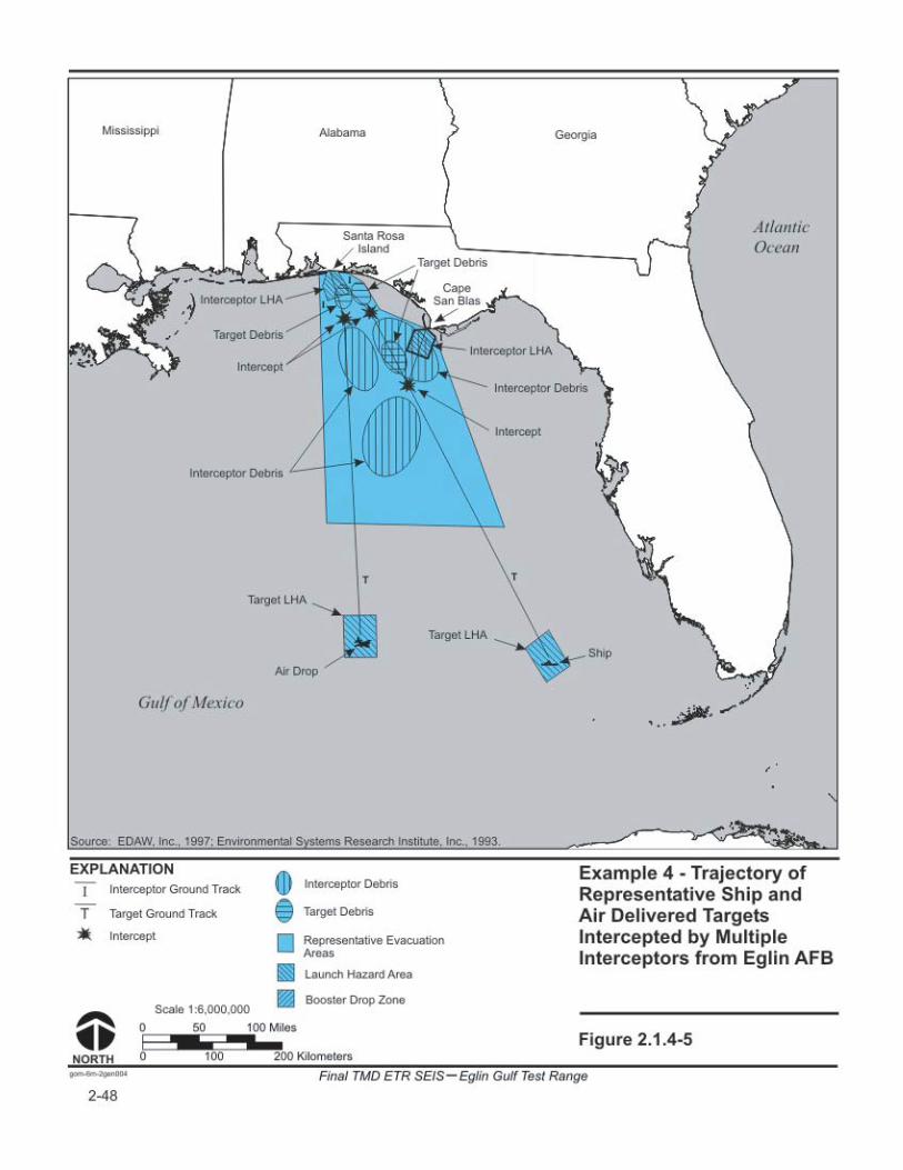
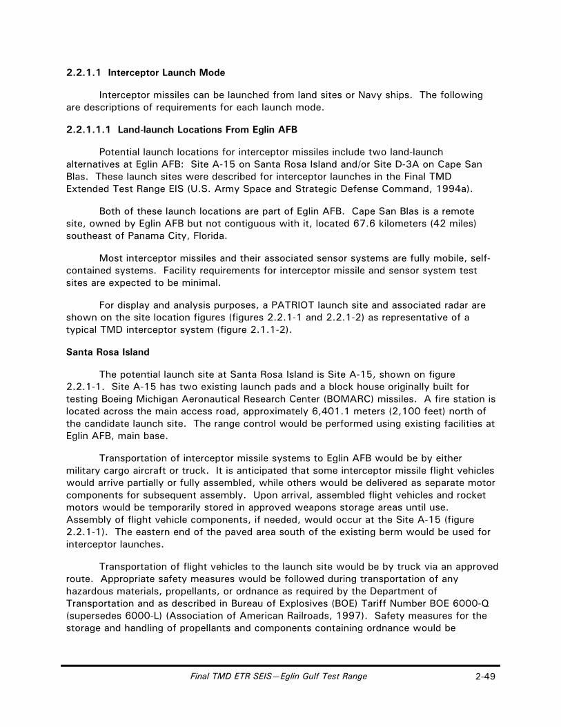
Final TMD ETR SEIS—Eglin Gulf Test Range 2-49
2.2.1.1 Interceptor Launch Mode
Interceptor missiles can be launched from land sites or Navy ships. The following are descriptions of requirements for each launch mode.
2.2.1.1.1 Land-launch Locations From Eglin AFB
Potential launch locations for interceptor missiles include two land-launch alternatives at Eglin AFB: Site A-15 on Santa Rosa Island and/or Site D-3A on Cape San Blas. These launch sites were described for interceptor launches in the Final TMD Extended Test Range EIS (U.S. Army Space and Strategic Defense Command, 1994a).
Both of these launch locations are part of Eglin AFB. Cape San Blas is a remote site, owned by Eglin AFB but not contiguous with it, located 67.6 kilometers (42 miles) southeast of Panama City, Florida.
Most interceptor missiles and their associated sensor systems are fully mobile, self-contained systems. Facility requirements for interceptor missile and sensor system test sites are expected to be minimal.
For display and analysis purposes, a PATRIOT launch site and associated radar are shown on the site location figures (figures 2.2.1-1 and 2.2.1-2) as representative of a typical TMD interceptor system (figure 2.1.1-2).
Santa Rosa Island
The potential launch site at Santa Rosa Island is Site A-15, shown on figure 2.2.1-1. Site A-15 has two existing launch pads and a block house originally built for testing Boeing Michigan Aeronautical Research Center (BOMARC) missiles. A fire station is located across the main access road, approximately 6,401.1 meters (2,100 feet) north of the candidate launch site. The range control would be performed using existing facilities at Eglin AFB, main base.
Transportation of interceptor missile systems to Eglin AFB would be by either military cargo aircraft or truck. It is anticipated that some interceptor missile flight vehicles would arrive partially or fully assembled, while others would be delivered as separate motor components for subsequent assembly. Upon arrival, assembled flight vehicles and rocket motors would be temporarily stored in approved weapons storage areas until use. Assembly of flight vehicle components, if needed, would occur at the Site A-15 (figure 2.2.1-1). The eastern end of the paved area south of the existing berm would be used for interceptor launches.
Transportation of flight vehicles to the launch site would be by truck via an approved route. Appropriate safety measures would be followed during transportation of any hazardous materials, propellants, or ordnance as required by the Department of Transportation and as described in Bureau of Explosives (BOE) Tariff Number BOE 6000-Q (supersedes 6000-L) (Association of American Railroads, 1997). Safety measures for the storage and handling of propellants and components containing ordnance would be

0 800 1,600 Feet
0 250 500 MetersNORTH
Scale 1:9,600
sri-9600-2hs001
Existing Berm
InterceptorRadar Site
MissileAssemblyBuilding
Proposed Launch Operations Trailer Shelter
Santa Rosa Island, Florida
Proposed Site A-15 Launch Site
Figure 2.2.1-1
EXPLANATION
Florida Panhandle
Index Map
Existing Building/Structure
FenceRadar Hazard Area
Warning Buoys (Proposed)
Government Property
Santa Rosa Sound
Gulf of Mexico
Source: Florida Marine Research Institute, 1995; U.S. Department of the Air Force, Air Force Material Command, 1989.
InterceptorLaunch Site
Proposed TargetLaunch Pad
2-50
Final TMD ETR SEIS Eglin Gulf Test Range

Existing Building/Structure
NORTH
Scale 1:9,600
Fence
Cape San Blas, Florida
Proposed Site D-3A Launch Site
Figure 2.2.1-2
EXPLANATION
Paved Area
Proposed Clearing Area
csb-9600-2hs003
Government Property
Wooded Area
Proposed LaunchEquipment Building
Proposed Target LaunchOperations Trailer Shelter
InterceptorLauncher
Proposed TargetLaunch Pad
InterceptorRadar Site
TargetRDAS
TargetRDAS
Radar Hazard Area
Site D-3
Site D-3A
ProposedIgloo
County Road30E
County Road30E
Proposed Target MissileAssembly Building
Warning Buoys
Florida Panhandle
Index Map
Note: RDAS = Real-time Data Acquisition System
0 400 800 Feet
0 125 250 Meters
Gulf of Mexico
Source: Florida Marine Research Institute, 1995; U.S. Department of the Air Force, 1994a,b.
2-51
Final TMD ETR SEIS Eglin Gulf Test Range

2-52 Final TMD ETR SEIS—Eglin Gulf Test Range
followed in accordance with DOD Directive 6055.9-STD, DOD Explosives Safety Board an DOD Component Explosive Safety Responsibilities (U.S. Department of Defense, 1987) and Air Force Manual 91-20, Explosive Safety Standards (supersedes Air Force Regulation 127-100) (U.S. Air Force, 1994).
Cape San Blas, Site D-3A
Eglin AFB owns and operates 210.4 hectares (520 acres) at Cape San Blas where the program flight operations would be performed. Existing facilities at Site D-3A could meet some or all facility requirements. Ground and Range Safety protocol requirements would be the same as for the Santa Rosa Island launch location option. (U.S. Army Space and Strategic Defense Command, 1994a)
The potential launch site at Cape San Blas (figure 2.2.1-2) is within Site D-3A. The site has an existing launch pad for interceptor missiles and a small power distribution building, 13.4 square meters (144 square feet). Other launch pads previously at the site were destroyed by hurricane action in 1995.
Flight vehicle storage, assembly, and checkout would be performed at Site D-3A (figure 2.2.1-2). Transportation and on-base facility requirements would be the same as for the Santa Rosa Island option. The existing interceptor launch pad and nearby gravel areas would be used. Launch operations would be conducted at Site D-3.
2.2.1.1.2 Navy AEGIS Ship
Although the Navy has no current plans to conduct TMD testing at the EGTR, interceptor launches could occur from an AEGIS ship at any location within the Gulf of Mexico dictated by the specific test or training requirements. Each intercept test scenario would be analyzed in advance using computer modeling predictions of where the missiles and resulting debris would land. U.S. Navy standard operating procedures for missile testing and training would be followed.
2.2.1.2 Target Launch Mode
There are two target modes being considered: air delivery and land-launched. Following is a brief description of the requirements for each.
2.2.1.2.1 Air Delivery Locations
Airborne delivery of target missiles could be made over the Gulf of Mexico, within the boundaries of the EGTR airspace, or from over the Gulf of Mexico within temporarily designated airspace outside the EGTR. All intercepts would be within the confines of the EGTR.
Air Drop refers to the parachute launch of a target missile from within a C-130 aircraft. Planned Air Drop targets would have ranges of up to 600 kilometers (373 miles) (launch point to aim point).

Final TMD ETR SEIS—Eglin Gulf Test Range 2-53
Air-launches of target missiles with ranges greater than 600 kilometers (373 miles) may be used in the future. Air-launch refers to the launch of a long-range, winged target missile from under the wing of a launch aircraft.
Eglin AFB would be the air delivery support installation. Aircraft that would be used to launch either Air Drop or air-launched target missiles would take off and land at Eglin AFB.
2.2.1.2.2 Land-launch Locations from Eglin AFB
Potential launch locations for target missiles include land-launch alternatives at Eglin AFB, Site A-15 on Santa Rosa Island, and/or Site D-3A on Cape San Blas (figures 2.2.1-1 and 2.2.1-2, respectively). Facilities and infrastructure requirements would be approximately equivalent for launches from either Site A-15 or Site D-3A. (U.S. Army Space and Strategic Defense Command, 1994a). The types of facilities required are listed in table 2.1.2-2 and described in section 2.1.2.2. Some locations have existing facilities, while other locations would require construction of launch support facilities.
Santa Rosa Island
The proposed launch site at Site A-15 is shown on figure 2.2.1-1.
Construction Activities. The target launch pad would be constructed on an existing paved area south of the existing berm. The launch equipment building would be constructed adjacent to the pad on a paved area. Some road work may be required to facilitate access to the launch pad.
The LOT shelter would be constructed on an existing concrete pad at one end of a building damaged by Hurricane Opal.
The MAB would be located within an existing, unused building at the site, located east of the launch pad. The existing road to the building would be used for access.
The range control would be performed using existing facilities at Eglin AFB, main base. No site work would be required.
The location of the launch complex at Site A-15 would use the substation located adjacent to the existing block house. Some updates and modifications would be required.
The X RDAS would be located at Site A-18. The Y RDAS would be located on Eglin AFB, at Site A-20.
Optics and radar sites could include Site A-10, Site A-13, and Site A-18 (figure 2.2.1-1). No clearing would be needed, and existing roads would be used for access. The RDAS optic and radars would be mobile systems requiring only a flat area to park the equipment. No new parking would be required. Commercial power would be utilized, with backup generators.
The existing guardhouse on Santa Rosa Island would be used. No modification would be required.

2-54 Final TMD ETR SEIS—Eglin Gulf Test Range
Table 2.2.1-1 depicts the land requirements at Santa Rosa Island.
Table 2.2.1-1: Santa Rosa Island Land Requirements
Site A-15
Category hectares acres
Site, Government Property 1,367.87 3,380
Site, Previously Undisturbed 1,312.69 3,243.65
Site, Previously Disturbed 55.18 136.35
Site, Total Wetlands 127.75 315.66
Proposed Action, Previously Undisturbed 0.04 0.10
Proposed Action, Previously Disturbed 0.76 1.88
Proposed Action, Wetlands Disturbed 0 0
Proposed Action, Total Footprint 0.8 1.98
Disturbed Wetlands as a Percent of Total Wetlands 0 0
Cape San Blas
The proposed launch site at Site D-3A is shown on figure 2.2.1-2.
Construction Activities. A new launch pad would be required immediately east of the existing interceptor launch pad. Minor road upgrades would likely be required from Route 30E to the launch pad.
The LOT shelter would be located northeast of the launch pad, along the access road. Clearing of probable wetland areas and minor upgrades to the road would be required.
The MAB would be located north of the LOT shelter, with a new access road and new parking and turnaround areas.
The range control would use existing facilities at the main area of Site D-3A and the main base area on Eglin. No site work would be required.
The X RDAS would be located adjacent to or on the roof of the range control building. The Y RDAS would be located at the northern corner of the site, between the beach and County Road 30E.
The power distribution building would provide power to the LOT shelter and launch site. Power would be delivered to the MAB along new lines from the distribution building.
Range support instrumentation for launches from Site D-3A would utilize existing range assets or be located on previously disturbed sites as appropriate for the individual test.
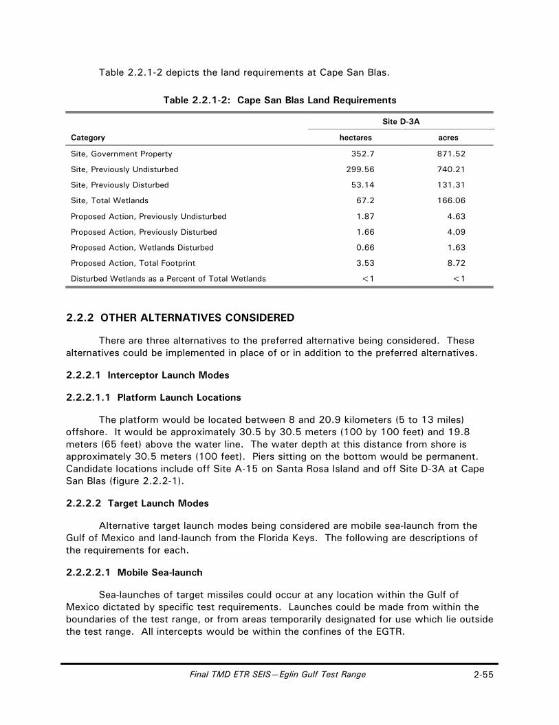
Final TMD ETR SEIS—Eglin Gulf Test Range 2-55
Table 2.2.1-2 depicts the land requirements at Cape San Blas.
Table 2.2.1-2: Cape San Blas Land Requirements
Site D-3A
Category hectares acres
Site, Government Property 352.7 871.52
Site, Previously Undisturbed 299.56 740.21
Site, Previously Disturbed 53.14 131.31
Site, Total Wetlands 67.2 166.06
Proposed Action, Previously Undisturbed 1.87 4.63
Proposed Action, Previously Disturbed 1.66 4.09
Proposed Action, Wetlands Disturbed 0.66 1.63
Proposed Action, Total Footprint 3.53 8.72
Disturbed Wetlands as a Percent of Total Wetlands <1 <1
2.2.2 OTHER ALTERNATIVES CONSIDERED
There are three alternatives to the preferred alternative being considered. These alternatives could be implemented in place of or in addition to the preferred alternatives.
2.2.2.1 Interceptor Launch Modes
2.2.2.1.1 Platform Launch Locations
The platform would be located between 8 and 20.9 kilometers (5 to 13 miles) offshore. It would be approximately 30.5 by 30.5 meters (100 by 100 feet) and 19.8 meters (65 feet) above the water line. The water depth at this distance from shore is approximately 30.5 meters (100 feet). Piers sitting on the bottom would be permanent. Candidate locations include off Site A-15 on Santa Rosa Island and off Site D-3A at Cape San Blas (figure 2.2.2-1).
2.2.2.2 Target Launch Modes
Alternative target launch modes being considered are mobile sea-launch from the Gulf of Mexico and land-launch from the Florida Keys. The following are descriptions of the requirements for each.
2.2.2.2.1 Mobile Sea-launch
Sea-launches of target missiles could occur at any location within the Gulf of Mexico dictated by specific test requirements. Launches could be made from within the boundaries of the test range, or from areas temporarily designated for use which lie outside the test range. All intercepts would be within the confines of the EGTR.
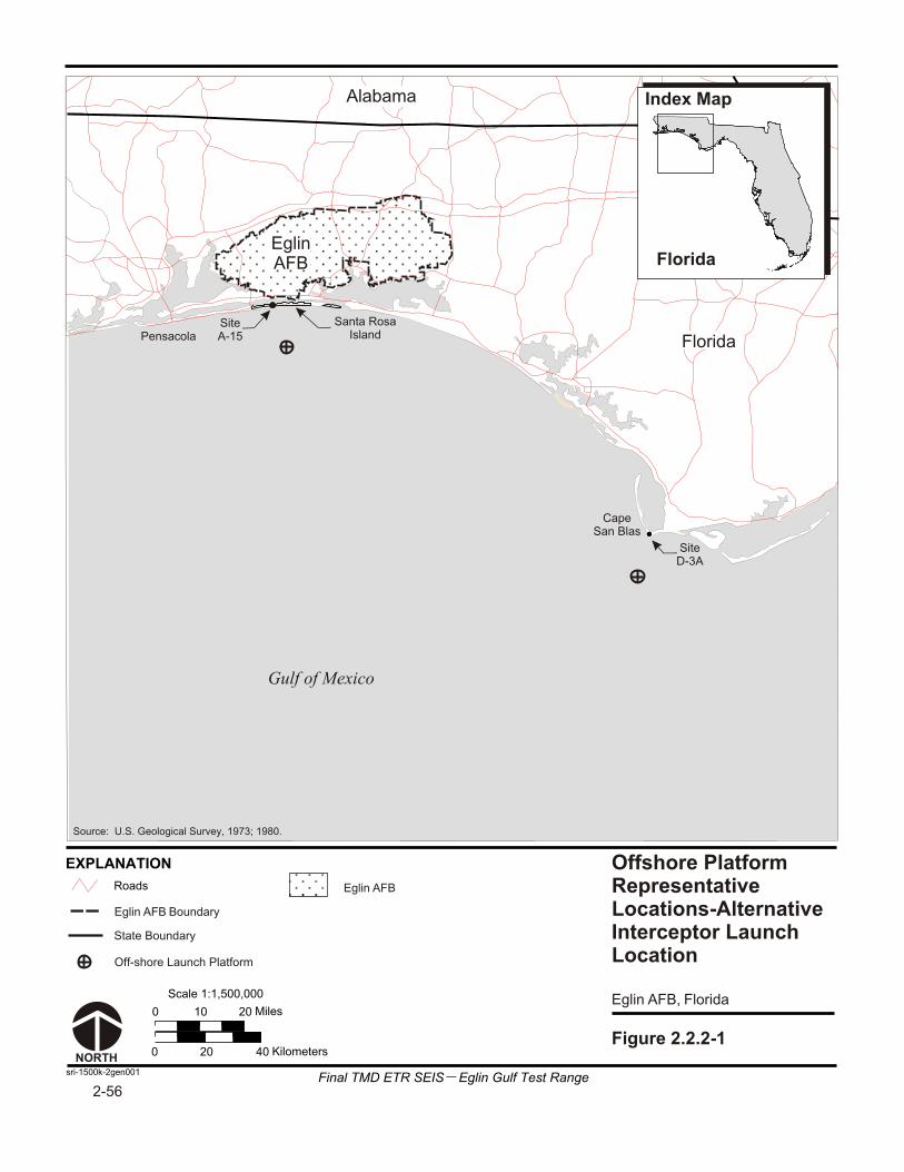
Roads
Scale 1:1,500,000
0 10 20 Miles
0 20 40 Kilometers
sri-1500k-2gen001
EXPLANATION
NORTH
Figure 2.2.2-1
Gulf of Mexico
Santa Rosa Island
Cape San Blas
Pensacola
Off-shore Launch Platform
Offshore PlatformRepresentativeLocations-AlternativeInterceptor LaunchLocation
Florida
Index Map
Eglin AFB Boundary
Eglin AFB, Florida
Eglin AFB
Site A-15
SiteD-3A
State Boundary
Alabama
Florida
Eglin AFB
Source: U.S. Geological Survey, 1973; 1980.
2-56Final TMD ETR SEIS Eglin Gulf Test Range

Final TMD ETR SEIS—Eglin Gulf Test Range 2-57
The BMDO is developing two sea-launch target programs, Mobile Aerial Target Support System (MATSS) and Sea Launch Platform (SLP). For consistency we will refer to these programs as sea-launched targets.
The target launch ship would be berthed in a support installation during those periods between use. The target launch ship could be berthed at a commercial pier and moved to a safety-certified explosive handling facility for the loading of the missile components before being towed to the required target launch location in the Gulf of Mexico. After the flight test, the target launch ship would be towed back to its storage berth until the next cycle of missile loading, preparation, and launch.
2.2.2.3 Land-launch from Florida Keys
Cudjoe Key and Saddlebunch Keys are the alternative candidates for target launch locations. If one is selected as a launch location, the other would be used as a supporting instrumentation site. Fleming Key, Boca Chica Key, and Sugarloaf Key are also candidate instrumentation locations.
Cudjoe Key
The existing facility at Cudjoe Key is an operational tethered aerostat radar site operated by the U.S. Air Force out of Langley AFB, Virginia. The site is located on the north end of Cudjoe Key approximately 3.2 kilometers (2 miles) from U.S. 1. The site includes two launch pads for the aerostats used for air interdiction radar and television transmission to Cuba. (U.S. Department of Defense, Ballistic Missile Defense Organization, 1995).
Due to the restricted size of this candidate site and the need to separate radar and optics from the launch pad at an optimum distance, not all target launch infrastructure could be placed on any one site, as shown on the vicinity location map for the Cudjoe Key launch alternative (figure 2.2.2-2).
Table 2.2.2-1 lists the activities and three options for operations. Option A includes Fleming Key for range control instrumentation; Option B does not use Fleming Key; and Option C uses the RASA aircraft for part of the instrumentation.
Construction Activities. The following sections describe construction activities for Options A, B, and C.
Option A. Figure 2.2.2-3 shows the existing and proposed infrastructure at the potential Cudjoe launch site. The location of the launch complex in this area would require that the substation and the underground electrical lines be upgraded. Construction of a launch pad at the current location of the paint shed adjacent to the vehicle maintenance facility (Building 12923) would be required. The launch equipment building and environmental shelter would be located on the launch pad and would require no additional site work. The LOT shelter would be constructed adjacent to balloon Site 12937 in an existing parking area. Clearing would not be needed, and new access roads and parking areas would not be constructed at this site.

Lower Florida Keys
key-500k-2land001a
EXPLANATION
Straits of Florida
Gulf of Mexico
Marquesas Keys
Key West
Saddlebunch Keys
Dredger's Key
Boca Chica Key
Fleming Key
Range Control, Radar #1 Sugarloaf Key
Vicinity Location Map,Cudjoe Key-AlternativeTarget Launch Location
Figure 2.2.2-2
Florida
Index Map
National WildlifeRefuge Boundary
Roads
AlternateRadar Site
Note: RDAS = Real-time Data Acquisition System
Potential Operations Area
8 Miles
NORTH
0 4
0 13 Kilometers6.5
Scale 1:500,000
Radar and Optics
“Y” RDAS
“X” RDAS
Launch Site
1
Cudjoe Key
2-58
Source: EDAW, Inc., 1997; Environmental Systems Research Institute, Inc., 1993;
Florida Marine Research Institute, undated; U.S. Geological Survey, 1980.
Final TMD ETR SEIS Eglin Gulf Test Range

cud-9600-2hs002
Figure 2.2.2-3
Replacement Paint Shed
ReplacementVehicle Maintenance
Optics # 1
EXPLANATION
Proposed Building/Concrete Pad
Existing Building/Structure
NORTH
0 800 1,600 Feet
0 250 500 Meters
Scale 1:9,600
Potential Launch SiteInfrastructure,Cudjoe Key-AlternativeTarget Launch SupportLocation
Launch Pad
LaunchEquipment Building
MissileAssemblyBuilding(Building# 12923)
Launch Operations Trailer Shelter
Gulf of Mexico
Government Property
Cudjoe Key, Florida
Warning Buoys (Proposed)
Florida Keys
Index Map
12937Aerostat Site
12938Aerostat Site
X RDAS (Option B)
X RDAS(Option A)
Note: RDAS = Real-time Data Acquisition System
Source: Naval Air Station, Key West, 1981; U.S. Department of the Navy, Naval Facilities Engineering Command, 1991.
2-59
Final TMD ETR SEIS Eglin Gulf Test Range

2-60 Final TMD ETR SEIS—Eglin Gulf Test Range
Table 2.2.2-1: Cudjoe Launch Site Facility Layout Matrix
Option A Option B (No Fleming) Option C (RASA Aircraft)
Launch Pad Existing Paint Shed Site (1)
Launch Operations Trailer Shelter
Parking Lot (2)
Missile Assembly Building
Use Existing Vehicle Maintenance Building
X RDAS Blimp Road (3) Near Aerostat 12938
Y RDAS Sugarloaf Key (4)
Optics #1 West of Aerostat 12938 RASA
Optics #2 Saddlebunch Keys (NW-J1706) RASA
Radar #1 Fleming Key or Boca Chica Key Saddlebunch Keys road RASA
Radar #2 Saddlebunch Keys (SE-J1706) RASA
Range Control Fleming Key Saddlebunch J1712 Partial RASA
Security New Gate West of Aerostat 12937
RASA = Remote Area Safety Aircraft (1) Relocate paint storage building to area south of Aerostat 12938 (2) Launch operations trailer shelter removes 10 parking spaces. Additional support trailers would occupy other parking
spaces. (3) X RDAS in county road right-of-way (4) Y RDAS on wildlife refuge land would require use-permit application to the U.S. Fish and Wildlife Service.
The existing vehicle maintenance facility would be converted into the MAB.
The boosters would be transported to the new MAB at Cudjoe Key. Range control would be located on Fleming Key. The existing hardstand would be used for trailer parking and operations. No site work would be required.
The X RDAS would be located along the access road into Sugarloaf Key (figure 2.2.2-4). The Y RDAS would be located adjacent to the entry road, approximately 304.8 meters (1,000 feet) from the guardshack on Cudjoe Key. The existing area would not need clearing. No new access road or additional parking would be required.
Optics Site Number 1 would be adjacent to balloon Site 12938. No clearing would be needed, and the existing road would be used for access. Optics Site Number 2 would be located along the main road on Saddlebunch Keys (figure 2.2.2-5). No clearing would be needed, and existing roads would be used for access. No new parking would be required.
Radar Site Number 1 would be located on Fleming Key near Range Control (figure 2.2.2-6). The existing hardstand would be used for parking and operations. No additional site work would be required. Radar Site Number 2 would be located on Saddlebunch Keys along the main road (figure 2.2.2-5). Clearing would not be required.
An alternative site for radar would be the unused Hawk site on Boca Chica Key (figure 2.2.2-7). Originally built as an air defense site for launching Hawk missiles, the facility is located on NASKW property, approximately 1.6 kilometers (1 mile) north of

Roads
Scale 1:100,000
0 1 2 Miles
0 1.5 3 Kilometers
cud-100k-2gen001
Gulf of Mexico
Cudjoe Key
Sugarloaf Key
Johnston Key
Big Torch Key
Knockemdown
Key
Summerland Key
EXPLANATION RDAS Site on Sugarloaf Key-Alternative TargetLaunch SupportLocation
NORTH
Figure 2.2.2-4
Proposed RDAS Site
Florida
Index Map
Sugarloaf Key, Florida
Note: RDAS = Real-time Data Acquisition System
SaddlebunchLaunch Option
RDAS Site
CudjoeLaunch Option
RDAS Site
Launch Site
Proposed Cudjoe Key Launch Site
2-61
Source: Environmental Systems Research Institute, Inc., 1993.
Final TMD ETR SEIS Eglin Gulf Test Range

sad-9600-2land001
EXPLANATION
Roads
Existing Building/Structure
0 800 1,600 Feet
0 125 250 500375
1,200400
Meters
Cudjoe Launch Instrumentation Sitesat Saddlebunch Keys-Alternative TargetLaunch SupportLocation
Figure 2.2.2-5
Scale 1:9,600
Optics # 2
Radar # 2
NORTH
Proposed Instrumentation
Saddlebunch Keys, Florida
Government Property
Big TorchKey
Florida Keys
Index Map
Range Control(Option B)
Radar #1 (Option B)
Building# J-1712
Source: Florida Marine Research Institute, undated; Naval Air Station, Key West, 1981.
2-62
Final TMD ETR SEIS Eglin Gulf Test Range
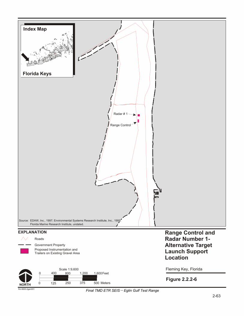
Range Control andRadar Number 1-Alternative TargetLaunch SupportLocation
Fleming Key, Florida
EXPLANATION
Proposed Instrumentation andTrailers on Existing Gravel Area
Roads
0
0
400 800 1,200 1,600
375 500250125
Feet
Meters
flm-9600-2gen001
Radar # 1
Range Control
Scale 1:9,600
NORTH
Figure 2.2.2-6
Government Property
Big TorchKey
Florida Keys
Index Map
2-63
Florida Marine Research Institute, undated.
Source: EDAW, Inc., 1997; Environmental Systems Research Institute, Inc., 1993;
Final TMD ETR SEIS Eglin Gulf Test Range

Roads
Scale 1:24,000
0 1,000 2,000 Feet
0 250 500 Meters
boc-24k-2noise001
Gulf of Mexico
Channel Key
Harper Key
Big Harper Key
Anonimo Key
Boca Chica Key
Duck Key
Boca Chica Key, Florida
EXPLANATION Radar Number 1Alternate Site, Saddlebunch Keys orCudjoe Key Launch-Alternative TargetLaunch Support Location
NORTH
Figure 2.2.2-7
Florida
Index Map
Radar #1
Hawk Site
2-64
Florida Marine Research Institute, undated.
Source: EDAW, Inc., 1997; Environmental Systems Research Institute, Inc., 1993;
Final TMD ETR SEIS Eglin Gulf Test Range
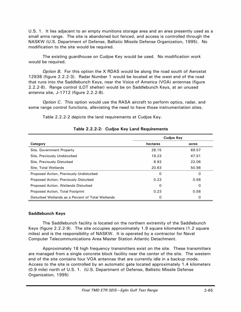
Final TMD ETR SEIS—Eglin Gulf Test Range 2-65
U.S. 1. It lies adjacent to an empty munitions storage area and an area presently used as a small arms range. The site is abandoned but fenced, and access is controlled through the NASKW (U.S. Department of Defense, Ballistic Missile Defense Organization, 1995). No modification to the site would be required.
The existing guardhouse on Cudjoe Key would be used. No modification work would be required.
Option B. For this option the X RDAS would be along the road south of Aerostat 12938 (figure 2.2.2-3). Radar Number 1 would be located at the west end of the road that runs into the Saddlebunch Keys, near the Voice of America (VOA) antennas (figure 2.2.2-8). Range control (LOT shelter) would be on Saddlebunch Keys, at an unused antenna site, J-1712 (figure 2.2.2-8).
Option C. This option would use the RASA aircraft to perform optics, radar, and some range control functions, alleviating the need to have those instrumentation sites.
Table 2.2.2-2 depicts the land requirements at Cudjoe Key.
Table 2.2.2-2: Cudjoe Key Land Requirements
Cudjoe Key
Category hectares acres
Site, Government Property 28.15 69.57
Site, Previously Undisturbed 19.23 47.51
Site, Previously Disturbed 8.93 22.06
Site, Total Wetlands 20.63 50.98
Proposed Action, Previously Undisturbed 0 0
Proposed Action, Previously Disturbed 0.23 0.58
Proposed Action, Wetlands Disturbed 0 0
Proposed Action, Total Footprint 0.23 0.58
Disturbed Wetlands as a Percent of Total Wetlands 0 0
Saddlebunch Keys
The Saddlebunch facility is located on the northern extremity of the Saddlebunch Keys (figure 2.2.2-9). The site occupies approximately 1.9 square kilometers (1.2 square miles) and is the responsibility of NASKW. It is operated by a contractor for Naval Computer Telecommunications Area Master Station Atlantic Detachment.
Approximately 18 high frequency transmitters exist on the site. These transmitters are managed from a single concrete block facility near the center of the site. The western end of the site contains four VOA antennas that are currently idle in a backup mode. Access to the site is controlled by an automatic gate located approximately 1.4 kilometers (0.9 mile) north of U.S. 1. (U.S. Department of Defense, Ballistic Missile Defense Organization, 1995)

sad-9600-2hs003
Saddlebunch Keys,Launch Option A-1-Alternative TargetLaunch Location
EXPLANATION
Gravel Fill Area
Existing Building/Structure
Saddlebunch Keys, Florida
NORTH
Proposed Launch Pad
Proposed LaunchEquipment Building
Proposed Launch Operations Trailer Shelter
Optics # 1
Government Property
Gulf of Mexico
ProposedMissile Assembly Building
0 800 1,600 Feet
0 250 500 Meters
Scale 1:9,600
Figure 2.2.2-8
Voice ofAmericaTowers
J-1570
Building# J-1561
“X” RDAS
Building# J-1712
Big TorchKey
Florida Keys
Index Map
Warning Buoys (Proposed)
J-1706
X RDAS (Option B)
Radar #1 (Option B)
Note: RDAS = Real-time Data Acquisition System
Instrumentation
2-66
Source: Department of the Navy, Naval Facilities Engineering Command, 1992;
EDAW, Inc., 1997; Florida Marine Research Institute, undated.
Final TMD ETR SEIS Eglin Gulf Test Range

Lower Florida Keys
key-500k-2land002
EXPLANATION
Straits of Florida
Gulf of Mexico
Marquesas Keys
Key West
Saddlebunch Keys
Dredger's Key
Boca Chica Key
Fleming Key
Range Control, Radar #1 Sugarloaf Key
Cudjoe Key
Site Location Map,Saddlebunch KeysLaunch Alternative-Alternative TargetLaunch Location
"Y” RDAS
Figure 2.2.2-9
Florida
Index Map
National WildlifeRefuge Boundary
Roads
AlternateRadar Site
Note: RDAS = Real-time Data Acquisition System
Potential Launch Sites
Potential Instrumentation Sites
Launch Site
Launch Site
8 Miles
NORTH
0 4
0 13 Kilometers6.5
Scale 1:500,000
Radar #2Optics #2
1
2-67
Source: Environmental Systems Research Institute, 1993;
Florida Marine Research Institute, undated.
Final TMD ETR SEIS Eglin Gulf Test Range

2-68 Final TMD ETR SEIS—Eglin Gulf Test Range
Due to the restricted size of this candidate site, proximity to wetlands, and the need to separate radar and optics from the launch pad at an optimum distance, not all target launch infrastructure could be placed on any one site.
Table 2.2.2-3 lists the activities and three options for operations. Option A includes Fleming Key for range control instrumentation; Option B does not use Fleming Key; and Option C uses the RASA aircraft for part of the instrumentation.
Table 2.2.2-3: Saddlebunch Launch Site Facility Layout Matrix
Option A Option B (No Fleming)
Option C (RASA Aircraft)
Launch Pad Option A-1: West end of Road (1) or Option A-2: West of Voice of America (VOA) antennas (1)
– –
Launch Operations Trailer Shelter
Southeast of Antenna J-1569 (1) – –
Missile Assembly Building
Option A-1: Unused Antenna Site J-1712 (1) or Option A-2: West of VOA Antennas (1)
– –
X RDAS At J-1712 Near Missile Assembly Building (1) Across From J-1706
Y RDAS Sugarloaf Keys (2) – –
Optics #1 Northwest of J-1706 – RASA
Optics #2 Cudjoe Key Launch Pad Area – RASA
Radar #1 Fleming Key or Boca Chica Key Southeast of J-1706 RASA
Radar #2 Cudjoe Key Launch Pad Area RASA
Range Control Fleming Key Cudjoe Key, northwest of Aerostat 12938
Partial RASA
Security Fence at Missile Assembly Building Area (1)
Notes: RASA = Remote Area Safety Aircraft (1) Section 404 permit application required (2) Y-RDAS located on wildlife refuge land would require use-permit application to the U.S. Fish and Wildlife Service
Construction Activities. The following sections describe construction activities for Options A-1, A-2, B, and C.
Option A-1. Figure 2.2.2-5 shows the existing and proposed infrastructure at the potential Saddlebunch Keys launch site. The Launch Pad Complex would be located at the north end of the existing gravel road near the VOA towers. The road may need to be widened in two locations. The Launch Equipment Building and Environmental Shelter would be located on the launch pad and would require no additional ground disturbance.
The LOT Shelter would be located across the road and west of Antenna Site J-1570. This site would require some cutting, filling, and clearing. An existing access road would be upgraded and five new parking spaces provided.

Final TMD ETR SEIS—Eglin Gulf Test Range 2-69
The MAB would be located on the abandoned Antenna Site J-1712. Clearing would be required for the building. The existing road to the site would be used for access. Range Control would be located in Fleming Key (figure 2.2.2-6). The existing hardstand would be used for trailer parking and operations. No site work would be required. The X RDAS would be located adjacent to the MAB (figure 2.2.2-8). The Y RDAS (figure 2.2.2-9) would be located along the access road to Sugarloaf Key.
The Radar Site Number 1 (figure 2.2.2-6) would be located on Fleming Key near Range Control. The existing hardstand would be used for parking and operations. No site work would be required. Radar Site Number 2 and Optics Site Number 2 would be located on the paved area near the maintenance facility on Cudjoe Key (figure 2.2.2-10). No clearing would be required, and existing roads would be used for access.
An alternative site for radar would be the unused Hawk site on Boca Chica Key (figure 2.2.2-7). Originally built as an air defense site for launching Hawk missiles, the facility is located on NASKW property, approximately 1.6 kilometers (1 mile) north of U.S. 1. It lies adjacent to an empty munitions storage area and an area presently used as a small arms range. The site is abandoned but fenced, and access is controlled through the NASKW (U.S. Department of Defense, Ballistic Missile Defense Organization, 1995). No site work would be required.
Existing power distribution lines are rated 13.8 kilovolts (kV) and are overhead lines from the highway to the outer gate of the Saddlebunch site. From the outer gate to the transformer yard adjacent to Building J1561, the 13.8-kV lines are direct-buried. The transformer yard contains one 500-kilovolt-ampere (kVA), 13.8-kV–120/208-volt (V), 3-phase transformer and one 225-kVA, 13.8-kV–480/277-V, 3-phase transformer. The location of the launch complex in this area would require that a new 13.8-kV–480-V transformer be located in the transformer yard and new underground distribution lines be installed.
Option A-2. Figure 2.2.2-10 shows the alternative existing and proposed infrastructure at Saddlebunch Keys. The launch pad complex would be located approximately 137.2 meters (450 feet) west of the VOA towers. The launch equipment room and environmental shelter would be located on the launch pad. The MAB would be located adjacent to and north of the launch pad. A fenced equipment storage yard would be next to the MAB. A gravel road would be constructed, and the site of the launch pad complex and MAB would be filled 0.9 meter (3 feet) to raise it above flood level.
The remaining facilities would be the same as Option A-1.
Option B. For this option the X RDAS would be located along the road, across from Antenna Site J-1706; Radar Number 1 would be located along the road, southeast of Antenna Site J-1706; and range control would be located at Cudjoe Key, northwest of Aerostat 12938.
Option C. This option would use the RASA aircraft to perform optics, radar, and some range control functions, alleviating the need to have those instrumentation sites.
Table 2.2.2-4 depicts the land requirements at Saddlebunch Keys.
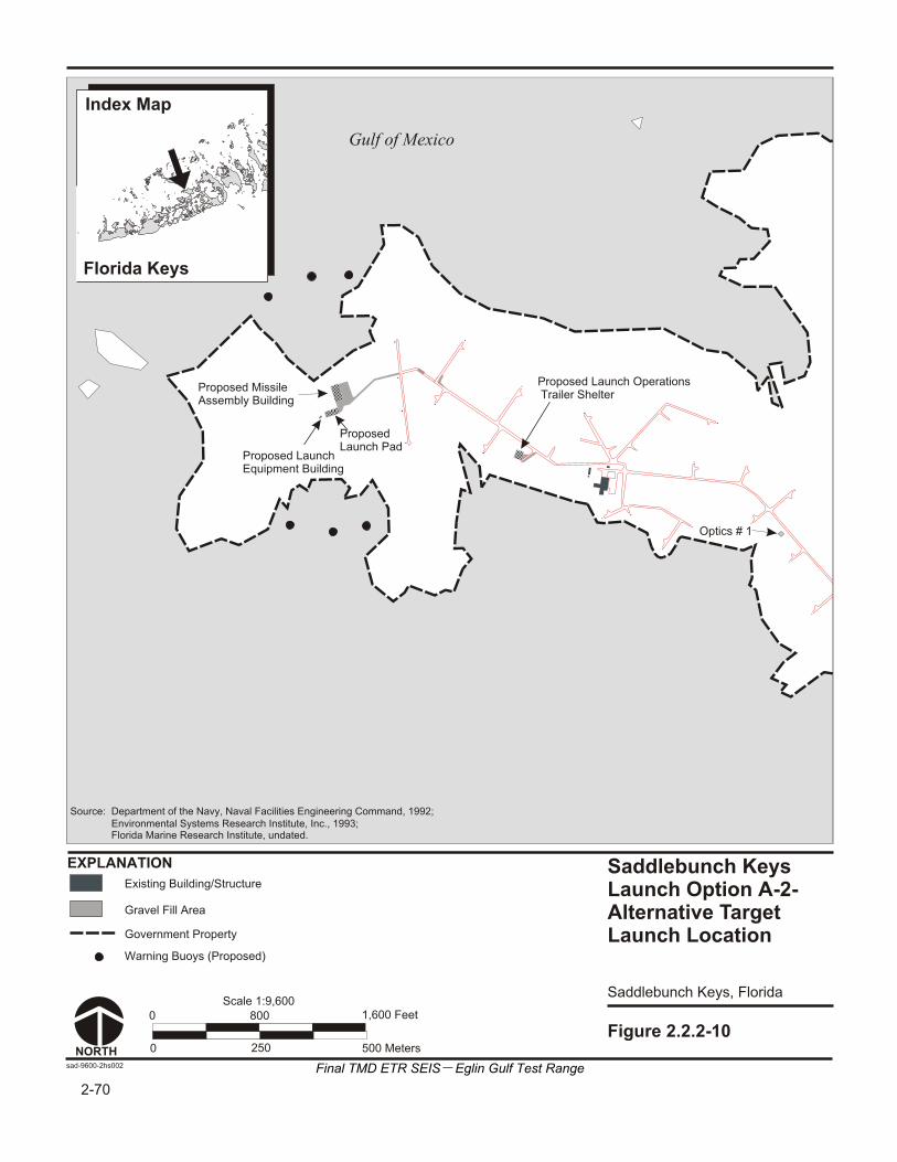
Figure 2.2.2-10
Saddlebunch KeysLaunch Option A-2-Alternative TargetLaunch Location
sad-9600-2hs002
0 800 1,600 Feet
0 250 500 Meters
Gravel Fill Area
Existing Building/Structure
NORTH
Scale 1:9,600
EXPLANATION
Gulf of Mexico
Proposed Missile Assembly Building
Proposed Launch Pad
Proposed LaunchEquipment Building
Proposed Launch Operations Trailer Shelter
Optics # 1
Saddlebunch Keys, Florida
Florida Keys
Index Map
Government Property
Warning Buoys (Proposed)
2-70
Source: Department of the Navy, Naval Facilities Engineering Command, 1992;
Florida Marine Research Institute, undated. Environmental Systems Research Institute, Inc., 1993;
Final TMD ETR SEIS Eglin Gulf Test Range

Final TMD ETR SEIS—Eglin Gulf Test Range 2-71
Table 2.2.2-4: Saddlebunch Keys Land Requirements
Category Saddlebunch Keys 1 Saddlebunch Keys 2 hectares acres hectares acres
Site, Government Property 242.1 598.3 242.1 598.3
Site, Previously Undisturbed 230.0 568.3 230.0 568.3
Site, Previously Disturbed 12.1 30.0 12.1 30.0
Site, Total Wetlands 227.3 561.8 227.3 561.8
Proposed Action, Previously Undisturbed 0.40 0.98 0.72 1.79
Proposed Action, Previously Disturbed 0.23 0.58 0.18 0.44
Proposed Action, Wetlands Disturbed 0.63 1.56 0.90 2.23
Proposed Action, Total Footprint 0.63 1.56 0.90 2.23
Disturbed Wetlands as a Percent of Total Wetlands <1 <1 <1 <1
2.2.3 NO-ACTION ALTERNATIVE
The AFDTC, located at Eglin AFB, has been a weapons development test center for more than 50 years. In FY 1995, Eglin personnel supervised more than 10,000 weapons test or training missions on Eglin ranges. Under the no-action alternative, the EGTR would not be enhanced to conduct TMD testing and training over the EGTR. Ongoing activities at Eglin AFB would continue in accordance with the Eglin Range General Plan “A Framework for the Future” (Eglin Air Force Base, 1996).
Eglin AFB currently manages more than 187,780 hectares (464,000 acres) of land and 336,674 square kilometers (130,000 square miles) of airspace. The 336,674-square kilometer (130,000-square mile) EGTR is composed of Air Force Controlled Warning Areas, Eglin Water Test Areas, and Navy Controlled Warning Areas.
Eglin AFB has a broad range of topographies and environments that make it very flexible for offering test programs options that represent air, land, sea, littoral, or space environments for test or training requirements. The existing instrumentation enables programs to gather high fidelity real-time data on the performance of their systems.
Currently, Eglin AFB supports over 10,000 weapons testing or training missions on its Land and Water Test Ranges per year. The Restricted Airspace utilization, in terms of hours scheduled over Santa Rosa Island, accounts for approximately 445 hours per year, while 3,543 hours per year were scheduled in the warning airspace close offshore. The use of airspace becomes sparser further offshore. The Eglin Water Test Area airspace is used primarily for test events rather than training, and it is generally scheduled for less than 150 hours per year. (Setterberg, Monteith, and Jordan, 1997)
Several activities would continue at sites on Santa Rosa Island with sustained levels of environmental effects. Under the Santa Rosa Island Reconstitution Test Capability project, construction is planned at three sites on the island. Site A-10 is

2-72 Final TMD ETR SEIS—Eglin Gulf Test Range
currently used as an instrumentation site for Eglin AFB. Site A-15, a former BOMARC missile test site, is minimally manned.
Existing facilities at Site D-3A on Cape San Blas include the Eglin AFB Missile Tracking Annex (MTA), U.S. Coast Guard Loran Station, and a lighthouse. The MTA contains radar systems, telemetry systems, instrumentation, command and control equipment, and other electromagnetic test equipment. These activities would continue in operation, sustaining current levels of environmental effects.
Clearing areas of non-essential people is a standard part of supervising weapons testing and training, and these activities would continue without the TMD program. Commercial fishing and shipping activities would also continue to operate in the Gulf of Mexico as would numerous recreational activities. The environmental effects of these activities would continue at current levels.
Developed areas on Cudjoe Key include the aerostat radar site operated by the U.S. Air Force, the Cudjoe Key Incinerator/Transfer Station and Emergency Landfill, a residential subdivision with 20 homes, a mobile home park, a day-care center, and various recreational facilities. These facilities and activities would remain with continuing environmental effects.
Developed areas in the Saddlebunch Keys include the Naval Computer Telecommunications Area Master Station Atlantic Detachment, four VOA antennas, a recreational vehicle park, two residential subdivisions, and a trailer park. Approximately 175 homes are located in the residential areas. These facilities and activities would remain in their current use with continuing environmental effects.
Should TMD testing or training not come to the EGTR, the mission utilization planned for in the Eglin Range General Plan would not be affected.
2.3 ALTERNATIVES ELIMINATED FROM FURTHER CONSIDERATION
Several launch modes and sites were initially screened and evaluated to determine their capability to meet TMD testing and training requirements using Eglin AFB as the supporting range. They included short- and long-range delivery of targets from a specially configured airplane, launch of targets from a ship, land-launch of targets and interceptors, and ship-launch of interceptors. The screening process focused on land-launch sites, as air- and ship-launches could be conducted from a wide variety of locations in the Gulf of Mexico.
Candidate target launch sites from land that were evaluated included:
Dry Tortugas, Florida
Yucatan Peninsula, Mexico
Matagorda Island, Texas
New island construction in the Gulf of Mexico

Final TMD ETR SEIS—Eglin Gulf Test Range 2-73
Eglin AFB, Florida
Boca Chica Key, Florida
Saddlebunch Keys, Florida
Cudjoe Key, Florida
Land-launch sites that were evaluated for interceptors from off-shore platforms at these locations were considered to provide safety areas. Land-based sites were evaluated according to the following criteria:
Launch site within mid-range intercept distance criteria of 500 to 1,100 kilometers (310.7 to 683.5 miles)
Debris from interceptor or target must not impact populated areas.
Target launch site must have enough area for support buildings and launch pad.
Launch site must be within DOD-controlled real estate, with sufficient size to allow establishment of an appropriate LHA.
Booster Drop Zone must be capable of being fully cleared at time of launch. The drop zone must be 20 by 20 kilometers (12.4 by 12.4 miles) and between 80 and 130 kilometers (49.7 and 80.8 miles) from launch.
Real estate requirements to support facilities to include a MAB (1 bay) with appropriate inhabited building ESQD zone and a launch pad ESQD zone
Obtainable real estate at launch area to install the interferometer RDAS in-line perpendicular to flight path a minimum of 1,000 meters (3,280.8 feet) uprange. Must be able to obtain clear line of sight to launch pad.
Site must not impact major highway or waterway traffic.
After each of the candidate land-launch sites was evaluated using the criteria, four candidates were identified for detailed study—Santa Rosa Island and Cape San Blas at Eglin AFB for the preferred alternative, and Saddlebunch Keys and Cudjoe Key in Monroe County as alternative launch locations. In addition, the sea-launch, air-launch, and Air Drop alternatives (for target launches) and launch platforms (for interceptor launches) were retained for detailed discussion.
2.3.1 LAUNCH FROM THE DRY TORTUGAS, FLORIDA
The Dry Tortugas is a National Park, with the main island almost completely covered by Fort Jefferson, an early 19th century masonry fortress which has National Monument status. Any TMD activities in this area could impact the historic character of Fort Jefferson and would not be consistent with its status as a National Monument.
Overpressure and blast from missile launches could damage the fragile mortar and brick components of the fort which are currently in a degraded condition. Sufficient area

2-74 Final TMD ETR SEIS—Eglin Gulf Test Range
does not exist on the island for the construction of launch site support facilities and instrumentation.
2.3.2 LAUNCH FROM THE YUCATAN PENINSULA, MEXICO
A possible target launch site in the Yucatan Peninsula is located on the shore near Dzilam de Bravo, Mexico. Target launch site flight distances from the Yucatan Peninsula to the proposed interceptor launch sites on Santa Rosa Island and Cape San Blas would be approximately 1,031.6 and 1,002.6 kilometers (641 and 623 miles), respectively. No DOD-owned infrastructure or facilities are available in the area, and great expense would be required to prepare launch sites. Distances to the Yucatan Peninsula would also greatly increase transportation costs related to construction and operation.
2.3.3 LAUNCH FROM MATAGORDA ISLAND, TEXAS
Matagorda Island is located off the coast of Texas, approximately 96.6 kilometers (60 miles) northeast of Corpus Christi. The island is 61.1 kilometers (38 miles) long and up to 6.4 kilometers (4 miles) wide and is the site of the deactivated Matagorda AFB, which was used as a launch site for a single stage ARIES rocket (M56 motor) commercial capability demonstration in 1981. Use of Matagorda Island would give target ranges of 900 to 1,000 kilometers (559.2 to 621.4 miles), depending upon which of the two interceptor launch sites (A-15 or D-3A) at Eglin AFB were used and the target launch heading. The entire flight path of the target missile would be overwater. Substantial test infrastructure would be needed at the Matagorda Island-launch site.
Flight modeling revealed that the flight path and booster drop zones of the target missile would be directly over areas with a high concentration of occupied oil drilling rigs. The inability to identify a safe booster drop zone and potential debris containment problems eliminated this alternative.
2.3.4 LAUNCH FROM BOCA CHICA KEY, FLORIDA
Boca Chica Key was eliminated as a potential launch site due to insufficient land area to establish an LHA that would not require clearance of U.S. 1.
2.3.5 NEW ISLAND CONSTRUCTION
A new island would be constructed in the Gulf of Mexico to provide a target launch site. The construction of a new island for a launch site would involve choosing the site, bringing in fill material to construct the site, and constructing launch facilities on the island. The island would be large enough to accommodate the launch pad, a MAB, and a launch operations building, separated by an ESQD of 381 meters (1,250 feet). Optics sites, RDAS, and radar sites would be positioned at other locations.
The high cost and length of time required to construct the island is not compatible with testing schedules; therefore, the alternative was eliminated.
Final TMD ETR SEIS—Eglin Gulf Test Range 2-75
2.4 COMPARISON OF ALTERNATIVES
A summary of potential environmental consequences resulting from testing and training activities proposed for the TMD Extended Test Range at the EGTR is presented in table 2.4-1.
Adverse Impacts represent potential environmental impacts that have a measured severity, extent, or duration that may require the application of appropriate mitigative actions.
Other potential environmental impacts may be noticeable and measurable, but which do not represent resource variance from exist conditions that would be consequential or require any mitigative action.
The preferred alternative would involve target and interceptor launch and support activities at alternative locations at Eglin AFB including Santa Rosa Island and Cape San Blas; Air Drop or air-launch of target missiles; and possible Navy AEGIS ship-launch of interceptor missiles. Interceptor and target flight tests from Site A-15 on Santa Rosa Island would result in some environmental impacts for biological resources, cultural resources, land and water use, noise, socioeconomics, transportation and water resources. For Site D-3A on Cape San Blas, interceptor flight tests would result in some impacts on biological and cultural resources, land and water use, noise, socioeconomics, transportation, and water resources. Target launch tests at Site D-3A would result in adverse impacts to biological resources and for geology and soils with the loss of 0.6 hectare (1.6 acres) of wetlands and possible disturbance of sensitive species. Potential target launch effects on the lighthouse and keeper’s quarters would cause adverse impacts to cultural resources on Cape San Blas. The Air Drop or air-launch of target missiles and the possible launch of interceptor missiles from Navy AEGIS ships would result in minor impacts on biological resources, land and water use, socioeconomics, and transportation. Flight test activities over the Gulf of Mexico including both interceptor and target missiles would result in minimal impacts to biological resources and noise.
Other alternatives include interceptor launch from offshore platforms off the coast of Santa Rosa Island and Cape San Blas; target missile launch from a sea-launch vessel; and, target launch and support activities at alternative locations in the Florida Keys (Cudjoe Key or Saddlebunch Keys). The installation and operation of offshore platforms for interceptor flight tests would result in minimal environmental impacts to biological resources, socioeconomics, and transportation for both the Santa Rosa Island and Cape San Blas sites. Potential impacts from target missile launch from a sea-launch vessel would be minor impacts to socioeconomics and transportation. Target launch test from Cudjoe Key could result in adverse impacts to cultural resources with possible disturbance of potentially National Register of Historic Places (NRHP) eligible Cold War sites. At Cudjoe Key, site preparation and target flight test activity would result in some environmental impacts for biological resources, land and water use, noise, socioeconomics, transportation, and water resources. Siting and operation of target launch tests at Saddlebunch Keys would result in adverse impacts to biological resources and geology and soils with the loss of 0.8 hectare (2.2 acres) of wetlands and possible disturbance of sensitive species. Other environmental impacts for the Saddlebunch Keys alternative

2-76 Final TMD ETR SEIS—Eglin Gulf Test Range
would be some impacts to land and water use, noise, socioeconomics, transportation, and water resources.
EO 12898, Environmental Justice, was issued to ensure that Federal agencies analyzed “the environmental effects, including human health, economic and social effects of Federal actions, including effects on minority communities and low-income communities, when such analysis is required by the NEPA 42 USC Section 4321 et seq.” For the TMD program, the impact analysis within each resource area shows that environmental justice issues are not expected to arise as a result of the proposed alternatives, including the proposed action.
Potential safety impacts for all environmental resources were evaluated for both normal interceptor and target flight tests and for a series of defined mishaps. There are no safety impacts for normal flight test activity. There are no appreciable ecological or human health risks. There is little increased risk to mission personnel and the general public due to TMD mishaps. Air Force safety and health regulations and procedures are designed and enforced to minimize safety hazards to service members and the public. These regulations and procedures would be strictly followed. Potential hazards would be anticipated and mitigated in advance by safety clearance zones to minimize public exposure to any possible mishap scenario. A mishap would have adverse effects on air quality, biological resources, cultural resources, hazardous materials and waste, and noise.
Table 2.4-2 presents possible mitigations that have been identified in the SEIS for each launch mode and location.
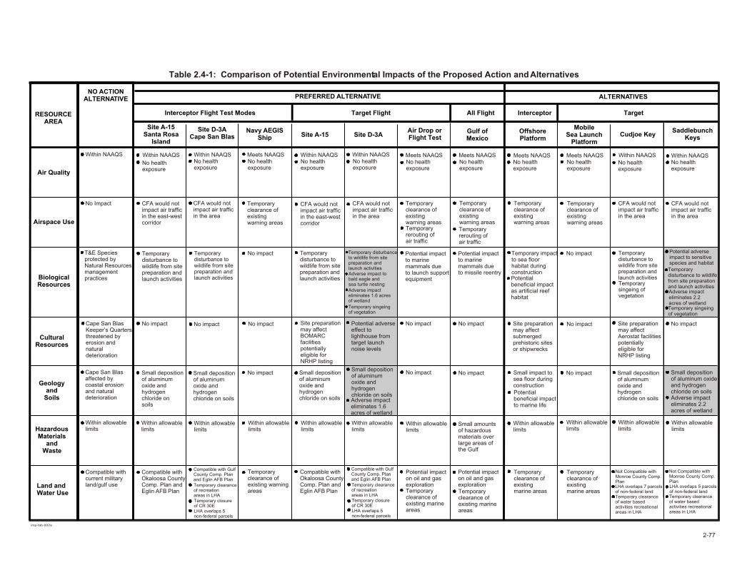
imp-tab-002a
Table 2.4-1: Comparison of Potential Environmental Impacts of the Proposed Action and Alternatives
2-77
RESOURCEAREA
NO ACTIONALTERNATIVE PREFERRED ALTERNATIVE ALTERNATIVES
Interceptor Flight Test Modes Target Flight All Flight Interceptor Target
Site A-15Santa Rosa
Island
Air Quality
Airspace Use
BiologicalResources
CulturalResources
Geologyand
Soils
HazardousMaterials
andWaste
Site D-3ACape San Blas
Navy AEGISShip Site A-15 Site D-3A
Air Drop orFlight Test
Gulf ofMexico
OffshorePlatform
MobileSea Launch
PlatformCudjoe Key
SaddlebunchKeys
Land andWater Use
Within NAAQS
No Impact
T&E Speciesprotected by Natural Resourcesmanagement practices
Cape San BlasKeeper’s Quartersthreatened byerosion andnaturaldeterioration
Cape San Blasaffected bycoastal erosionand naturaldeterioration
Within allowablelimits
Within allowablelimits
Within allowablelimits
Within allowablelimits
Within allowablelimits
Within allowablelimits
Within allowablelimits
Within allowablelimits
Within allowablelimits
Within allowablelimits
Within allowablelimits
Compatible withcurrent militaryland/gulf use
Within NAAQS
No healthexposure
Temporarydisturbance towildlife from sitepreparation andlaunch activities
Temporarydisturbance towildlife from sitepreparation andlaunch activities
Temporarydisturbance towildlife from sitepreparation andlaunch activities
Temporary disturbance to wildlife from sitepreparation andlaunch activities
No impact No impact Site preparationmay affectBOMARC facilities potentially eligible for NRHP listing
Small deposition of aluminum oxide and hydrogenchloride on soils
Small depositionof aluminum oxide and hydrogenchloride on soils
Small deposition of aluminum oxide and hydrogenchloride on soils
Small deposition of aluminum oxide and hydrogenchloride on soils
Small deposition of aluminum oxide and hydrogenchloride on soils
Small deposition of aluminum oxide and hydrogenchloride on soils
Compatible withOkaloosa CountyComp. Plan andEglin AFB Plan
Compatible withOkaloosa CountyComp. Plan andEglin AFB Plan
Temporary clearanceof recreationareas in LHA
Temporary clearanceof recreationareas in LHA
Compatible with Gulf County Comp. Plan and Eglin AFB Plan
Compatible with Gulf County Comp. Plan and Eglin AFB Plan
Temporary closureof CR 30E
Temporary closureof CR 30E
Temporaryclearance ofexisting warningareas
Potential impacton oil and gasexplorationTemporary clearance ofexisting marineareas
Potential impacton oil and gasexplorationTemporary clearance ofexisting marineareas
No healthexposure
Within NAAQSNo healthexposure
Meets NAAQSNo healthexposure
Within NAAQSNo healthexposure
Within NAAQS
No healthexposure
Meets NAAQSNo healthexposure
Meets NAAQSNo healthexposure
Meets NAAQSNo healthexposure
Meets NAAQS
No healthexposure
Within NAAQSNo healthexposure
Within NAAQS
CFA would notimpact air trafficin the east-westcorridor
CFA would notimpact air trafficin the area
CFA would notimpact air trafficin the east-westcorridor
CFA would notimpact air trafficin the area
CFA would notimpact air trafficin the area
CFA would notimpact air trafficin the area
Temporary clearance ofexisting warning areas
Temporary clearance ofexisting warning areas
Temporary impactto sea floorhabitat duringconstruction
Temporary rerouting ofair traffic
Temporary rerouting ofair traffic
Temporary clearance ofexisting warning areas
Temporary clearance ofexisting warning areas
Temporary clearance ofexisting warning areas
No impact
No impact
No impact
Potential adverseeffect to lighthouse fromtarget launchnoise levels
Adverse impact to bald eagle and sea turtle nestingAdverse impact eliminates 1.6 acres of wetland
Adverse impacteliminates 2.2acres of wetland
Potential impact to marine mammals due to launch supportequipment
Potential impact to marine mammals due to missile reentry
Temporarydisturbance to wildlife from sitepreparation andlaunch activities
Temporarydisturbance to wildlife from site preparation and launch activities
Potential adverseimpact to sensitivespecies and habitat
No impactSmall impact to sea floor duringconstructionPotential beneficial impact to marine life
Small amountsof hazardousmaterials overlarge areas ofthe Gulf
Temporaryclearance of existingmarine areas
Temporaryclearance of existingmarine areas
Temporary clearance of water based activities recreational areas in LHA
Temporary clearance of water based activities recreational areas in LHA
Potential beneficial impactas artificial reefhabitat
No impact
No impactNo impact
No impactNo impact
No impact No impact
Temporary singeing ofvegetation
Temporary singeing of vegetation
Site preparationmay affectAerostat facilitiespotentiallyeligible forNRHP listing
Site preparationmay affectsubmergedprehistoric sitesor shipwrecks
Not Compatible with Monroe County Comp. Plan
Not Compatible with Monroe County Comp. Plan
LHA overlaps 7 parcelsof non-federal land
LHA overlaps 5 parcelsof non-federal land
LHA overlaps 5non-federal parcels
LHA overlaps 5non-federal parcels
Adverse impacteliminates 1.6 acres of wetland
Adverse impacteliminates 2.2acres of wetland
Temporary singeing of vegetation

imp-tab-002b
Table 2.4-1: Comparison of Potential Environmental Impacts of the Proposed Action and Alternatives (Continued)
2-78
RESOURCEAREA
NO ACTIONALTERNATIVE PREFERRED ALTERNATIVE ALTERNATIVES
Interceptor Flight Test Modes Target Flight All Flight Interceptor Target
Site A-15Santa Rosa
Island
Noise
Safety
Socio-economics
Transportation
Utilities
VisualAesthetics
Site D-3ACape San Blas
Navy AEGISShip Site A-15 Site D-3A
Air Drop orFlight Test
Gulf ofMexico
OffshorePlatform
MobileSea Launch
PlatformCudjoe Key
SaddlebunchKeys
WaterResources
Existing noisedue to militaryand civilian activity
No Impact
Currentemploymentand incometrends continue
Traffic growthin Fort WaltonBeach and Florida Keyswill exceedcurrent capacity
No impacts
Visual aestheticswithin currentmilitary context
Visual aestheticswithin currentmilitary context
Exhaust trailvisible forshort periodafter launch
Exhaust trailvisible forshort periodafter launch
Exhaust trailvisible forshort periodafter launch
Within currentmilitary visualcontext
Within currentmilitary visualcontext
Within currentmilitary visualcontext
Exhaust trailvisible forshort periodafter launch
Target missilevisible prior tolaunch
Target missilevisible prior tolaunch
Exhaust trailvisible forshort periodafter launch
Exhaust trailvisible forshort periodafter launch
Exhaust trailvisible forshort periodafter launchPlatform visibleoff-shore
Exhaust trailvisible forshort periodafter launch Target missile
visible prior to launch
Target missilevisible prior to launch
Increased percentage ofpeople highlyannoyed
Increased percentage ofpeople highlyannoyed
Increased percentage ofpeople highlyannoyed
Increased percentage ofpeople highlyannoyed
Increased percentage ofpeople highlyannoyed
Temporary impacts on commercial fishing, shipping,and recreation in LHA
Temporary impacts on commercial fishing, shipping,and recreation in LHA
Temporary impactson commercial fishing and recreation in LHA
Temporary impactson commercial fishing and recreation in LHA
Increase intraffic lessthan 1 percent
Increase intraffic lessthan 1 percent
Increase intraffic lessthan 40 percent
Within currentcapacity
Within currentcapacity
Within currentcapacity
Within currentcapacity
Temporaryshort termincrease inwater acidity
No impact Temporaryshort termincrease inwater acidity
Temporaryshort term increase inwater acidity
Temporaryshort term increase inwater acidity
No impact No impact Small amounts of propellant,emissions anddebris depositedover large debris areas
No impact Potential harmor harassmentof marine mammals dueto sonic boom
Potential impactto marine lifeduring constructionor launch activities
No healthrelated soundexposure beyondLHA No health
related soundexposure beyondLHA
No increasedhazard to public
Temporary impactson commercialfishing andrecreation in LHA
Temporary effectson commercialfishing andrecreation in LHA
Temporary effectson commercialfishing andrecreation in LHA
Temporary impact oncommercialfishing lessthan 1%
No impact No impact
Temporaryclearance ofexisting warningareas
No impact
Increase in traffic less than40 percent
Temporary clearance of existing warningareas
Temporaryclearance ofexisting warningareas
No impact Within currentcapacities
Within currentcapacities
Temporaryshort termincrease inturbidity duringconstruction
No impact Temporaryshort termincrease inwater acidity
Temporaryshort termincrease inwater acidity
No increasedhazard to public
No increasedhazard to public
No increasedhazard to public
No increasedhazard to public
No increasedhazard to public
No increasedhazard to public
No increasedhazard to public
No increasedhazard to public
No increasedhazard to public
No increasedhazard to public
Temporaryincrease inhousing demand
Temporaryincrease inhousing demand
Temporaryincrease inhousing demand
No impact
No impact No impact No impact
Increase intraffic less than0.5%
Increase intraffic less than1.5%
Temporaryclearance ofexisting warningareas
Temporary closing ofIntracoastal waterwayin LHA
Temporaryclearance ofexisting warningareas
No health relatedsound exposurebeyond LHA
No health relatedsound exposurebeyond LHA
No health relatedsound exposurebeyond LHA
No health relatedsound exposurebeyond LHA
No health relatedsound exposurebeyond LHA
No health relatedsound exposurebeyond LHA
No health relatedsound exposurebeyond LHA
Temporary increasein housing demand
Temporary increasein housing demand
Temporary increasein housing demand
Temporary increasein housing demand
Small beneficialincome increases
Small beneficialincome increases
Temporary closure of CR 30E
Temporary closure ofCR 30E
Temporary rerouting of shipping clearance
Temporaryrerouting ofshipping
Exhaust trailvisible for shortperiod afterlaunch
Exhaust trailvisible for shortperiod afterlaunch Consistent with
current militarycontext andblimp effects
Consistent withcurrent militarycontext andantennas effects
Temporary closure ofBlimp Road at Asturias

Final TMD ETR SEIS—Eglin Gulf Test Range 2-79
Table 2.4-2: Possible Mitigations by Mode and Location
Possible Mitigations
No
Act
ion
Alte
rnat
ive
Site
A-1
5 -
Inte
rcep
tor
Laun
ch
Site
D-3
A -
Inte
rcep
tor
Laun
ch
Nav
y A
EGIS
Shi
p -
Inte
rcep
tor
Laun
ch
Site
A-1
5 -
Her
a Tar
get
Laun
ch
Site
D-3
A -
Her
a Tar
get
Laun
ch
Air
Dro
p or
Flig
ht T
est
- Tar
get
Laun
ch
Gul
f of
Mex
ico
Off
shor
e Pl
atfo
rm -
Inte
rcep
tor
Laun
ch
Mob
ile S
ea L
aunc
h Pl
atfo
rm -
Tar
ghet
La
unch
Cud
joe
Key
- T
arge
t La
unch
Sad
dleb
unch
Key
s -
Tar
get
Laun
ch
Air quality monitoring before and after initial launchWind velocity and direction monitoring prior to launchDust suppression during constructionSchedule test activity to avoid breeding seasonsLow pressure sodium lighting aimed away from beachesHabitat enhancement, onsite, in-kindProcedures to minimize construction disturbancesContinue endangered species population surveys in LHAContinue plant surveys near launch pad before and after initial launchConduct endangered species population surveys in LHAConduct plant surveys near launch pad before and after initial launchConstruct sound barriers surrounding launch pad to reduce launch noiseBiological monitoring of mishap debris recoveryFinal site design to minimize habitat and wetlands disturbanceRelocate raptor roosts away from construction activitiesDetermination of NRHP eligibility for Cold War-era facilitiesArchaeological monitoring of mishap debris recoveryStop construction and evaluate site if cultural resources discovered404 (b) (1) evaluation and permit for wetlandsStandard construction practicesSites-specific emergency response plan in place prior to launchEnvironmental awareness briefing for onsite workersMinimize onsite refueling of vehiclesAdvance notification of LHA closure dates and durationsProperty easements for undeveloped lands within the LHAMinimize nighttime construction activitiesAdvance notification of scheduled launch Schedule component shipment and project traffic for off-peak hoursAdvance notification of road closuresUse bottled drinking water to reduce onsite water demandUse portable toilets or holding tanks with offsite wastewater treatmentDesign facilities for visual compatibilityDesign facilities to minimize reflective surfaces and bright colorsDesign facilities to minimize impervious surfacesEstablish procedures to minimize untreated surface runoffMonitor water quality near launch site before and after initial launch
Preferred Alternative Alternatives

2-80 Final TMD ETR SEIS—Eglin Gulf Test Range
THIS PAGE INTENTIONALLY LEFT BLANK