THE WATER INJECTION INTO THE FUEL CHANNEL USING THE ...
7
NUCLEAR – 2019 ████████████████████████████████████████████████████████████████████████████████████████████████████████████████████████████████████████████████████████████████████████████████████████████████████████████████████ ████████████████████████████████████████████████████████████████████████████████████████████████████████████████████████████████████████████████████████████████████████████████████████████████████████████████████ 246 ████████████████████████████████████████████████████████████████████████████████████████████████████████████████████████████████████████████████████████████████████████████████████████████████████████████████████ THE WATER INJECTION INTO THE FUEL CHANNEL USING THE MECHANICAL SIMULATOR A. POPESCU*, G. DUNA and S.C. VALECA Institute for Nuclear Research, Pitesti, Romania University of Pitesti, Romania*, [email protected] ABSTRACT The paper it’s focused on the water supply system of the fuelling machine head from fuelling machine testing rig. The fuelling machine head is part of the fuel handling system. The tests done on the water supply system, from the fuelling machine testing rig, had the purpose to demonstrate its capability to successfully achieve the testing of the fuelling machine head according to the requirements. The mechanical simulator is an equipment where are connected all the water trails of fuelling machine magazine. At the end of the paper is presented the test of water injection in the fuel channel using the mechanical simulator. The tests are performing the capability of the water supply system from the fuelling machine testing rig to provide the necessary operation parameters similar to those from CANDU reactor in the end having an educational role. Key words: fuel handling system, RAM adapter, guide sleeve, snout plug Introduction In 2003, for the first time in Romania and in Europe, the Nuclear Research Institute from Pitesti, successfully tested fuelling machine head (FMH) no. 4 – the CANDU reactor machine head for the Cernavoda Nuclear Power Station – Unit 2. In order to achieve these tests, a special testing rig was built at the Institute for Nuclear Research Pitesti, capable to ensure the necessary requests of the test, both the stand and the tested team being successfully evaluated by the AECL officials, before starting the testing activities. Constructively, the testing rig of the fuelling machine heads contain equipment similar to those from CANDU 600 reactor, such as: cart and suspension, fuel canals, biological shield plugs, catenary, thermo-hydraulic loop, fuel operating group, water valve station, control
Transcript of THE WATER INJECTION INTO THE FUEL CHANNEL USING THE ...

NUCLEAR – 2019
████████████████████████████████████████████████████████████████████████████████████████████████████████████████████████████████████████████████████████████████████████████████████████████████████████████████████
████████████████████████████████████████████████████████████████████████████████████████████████████████████████████████████████████████████████████████████████████████████████████████████████████████████████████
246
████████████████████████████████████████████████████████████████████████████████████████████████████████████████████████████████████████████████████████████████████████████████████████████████████████████████████
THE WATER INJECTION INTO THE FUEL CHANNEL USING THE
MECHANICAL SIMULATOR
A. POPESCU*, G. DUNA and S.C. VALECA
Institute for Nuclear Research, Pitesti, Romania
University of Pitesti, Romania*, [email protected]
ABSTRACT
The paper it’s focused on the water supply system of the fuelling machine head from
fuelling machine testing rig. The fuelling machine head is part of the fuel handling system.
The tests done on the water supply system, from the fuelling machine testing rig, had the
purpose to demonstrate its capability to successfully achieve the testing of the fuelling
machine head according to the requirements. The mechanical simulator is an equipment
where are connected all the water trails of fuelling machine magazine. At the end of the
paper is presented the test of water injection in the fuel channel using the mechanical
simulator. The tests are performing the capability of the water supply system from the
fuelling machine testing rig to provide the necessary operation parameters similar to those
from CANDU reactor in the end having an educational role.
Key words: fuel handling system, RAM adapter, guide sleeve, snout plug
Introduction
In 2003, for the first time in Romania and in Europe, the Nuclear Research Institute from
Pitesti, successfully tested fuelling machine head (FMH) no. 4 – the CANDU reactor
machine head for the Cernavoda Nuclear Power Station – Unit 2.
In order to achieve these tests, a special testing rig was built at the Institute for Nuclear
Research Pitesti, capable to ensure the necessary requests of the test, both the stand and the
tested team being successfully evaluated by the AECL officials, before starting the testing
activities.
Constructively, the testing rig of the fuelling machine heads contain equipment similar to
those from CANDU 600 reactor, such as: cart and suspension, fuel canals, biological shield
plugs, catenary, thermo-hydraulic loop, fuel operating group, water valve station, control

NUCLEAR – 2019
████████████████████████████████████████████████████████████████████████████████████████████████████████████████████████████████████████████████████████████████████████████████████████████████████████████████████
████████████████████████████████████████████████████████████████████████████████████████████████████████████████████████████████████████████████████████████████████████████████████████████████████████████████████
247
████████████████████████████████████████████████████████████████████████████████████████████████████████████████████████████████████████████████████████████████████████████████████████████████████████████████████
room with the connecting panels, the command desks and the control and command
processing computers of the technological process.
All the mentioned facilities from above, make the simulation and change in the testing rig of
the reactor’s thermo-hydraulic parameters while it works. All the testing rig operations are
monitored, correlated and coordinated from the control room by processing computers and
the testing operator / engineer.
Within the CANDU Nuclear Power Plant, the fuel handling system represent the total
amount of the equipment which ensure the transfer of the fresh fuel from the storage to the
fuelling machine head, switching it with the reactor in operation, and the transfer of burnt
fuel to the settling and storage tanks.
The system component parts are structured according to the nature of the performed
operation:
- transfer of fresh fuel;
- tuling Machine Head (the simplified representation in figure 1) ;
- transfer and Storage of burnt fuel.
In the fuel handling system, the most important component is represented by the fuelling
machine head. Because of the working conditions and the importance of a proper
functioning, the fuelling machine head is assisted and commanded during the operations
done by a processing computer which synthesizes the received information regarding the
active area of the reactor and the status of the position of different assemblies, making
component mechanisms work by giving the necessary commands in order to assure the
operations, the sequence and the phase needed at that moment [1].
Fig 1. Simplified representation for fuelling machine head, component parts
General presentation of the equipments involved in water injection test
From the constructive point of view the fuelling machine head is made of the following main
assemblies:
- snout assembly;
- fuel separators assembly;
- magazine assembly;
- RAM assembly;
- tools and accessories (FMH plug, guide sleeve, RAM adapter);
- oil assembly;
- water assembly.

NUCLEAR – 2019
████████████████████████████████████████████████████████████████████████████████████████████████████████████████████████████████████████████████████████████████████████████████████████████████████████████████████
████████████████████████████████████████████████████████████████████████████████████████████████████████████████████████████████████████████████████████████████████████████████████████████████████████████████████
248
████████████████████████████████████████████████████████████████████████████████████████████████████████████████████████████████████████████████████████████████████████████████████████████████████████████████████
The water supply system of the fuelling machine head is part of the fuelling machine testing
rig. This system is used to realize the command and the actions done with water by
subassemblies of the fuelling machine head. The water supply system of the fuelling machine
head represent the amount of equipment that provide, in the end, parameters (water pressures
and flow) to the fuelling machine head according to the testing requests. The water supply
system is composed of:
- the water demineralization and degassing preparation system;
- the water supply system of the water distribution panel (it assures the supply of the water
valve station – figure 2);
- water distribution panel (it assures the water supply of the fuelling machine head’s
elements);
- fuelling machine support and catenary systems;
- the air supply system of the elements pneumatically powered;
- the operation and control system of the fuelling machine head control room.
The water supply system has to assure at the entrance of the water distribution panel, pressure
at three levels, as it follows:
- HIGH 162 bar;
- MEDIUM 79 bar;
- LOW 34,5 bar.
Based on the supply pressure of the water distribution panel, it has to provide four pressure
levels to the Fuelling Machine Head magazine:
- HIGH: 114 bar;
- INTERMEDIATE: 110 bar;
- PARKING: 31 bar;
- LOW: 0 bar.
In order to demonstrate the fulfilment of the enumerated parameters, the water distribution
panel was connected to the mechanical simulator. The mechanical simulator, besides the
possibility of realizing the enumerated parameters, is also used to inject water into the testing
channel, proving the thermal stability of the hot and cold loops to maintain the working
parameters in real testing conditions (the fuelling machine head connected to the testing
canal). The mechanical simulator has to assure water in the following parameters when is
used to inject water into the testing channels:
- flow=1,5 l/s;
- Temperature=93 0C;
- Pressure=114 bar.

NUCLEAR – 2019
████████████████████████████████████████████████████████████████████████████████████████████████████████████████████████████████████████████████████████████████████████████████████████████████████████████████████
████████████████████████████████████████████████████████████████████████████████████████████████████████████████████████████████████████████████████████████████████████████████████████████████████████████████████
249
████████████████████████████████████████████████████████████████████████████████████████████████████████████████████████████████████████████████████████████████████████████████████████████████████████████████████
Fig 2. Water distribution panel
Fig 3. Mechanical simulator
The mechanical simulator is made of a collector, a pipe-line with a nominal diameter of 50
mm, on which they are mounted an adjusting valve, a retention clap, a flow meter and a
connecting system between the mechanical simulator and the test section (In figure 3 it’s
represented the mechanical simulator). The collector has 4 link nozzles to the water
distribution panel, 2 plugs for the thermocouple and a plug for the local pressure reading
(manometer).
The following pipe-line of the water distribution panel were connected to the collector of the
mechanical simulator through the hosepipes of the catenary:
- the magazine supply line;
- the magazine return line;
- the magazine pressure sensing pipe-line;
- the supplementary flow pipe-line.
During the hot or cold preaccepting and accepting tests, when the machine head is connected
to the fuelling channel, in the hot or cold loop is introduced a flow from the fuelling machine
magazine of 1,5 l/sec, at a pressure of 110 bar in the testing channel (similar with the flow
introduced in the fuel channel when the CANDU nuclear power station works). The
maximum temperature of the injected fluid is about 900C for the hot loop and a temperature of
540C for the cold loop.
The water injection into the fuel channel is necessary, when the nuclear power plant works, to
prevent water contamination in the primary circuit of the fuelling machine head of the reactor.
It also prevents thermal shocks in the fuelling machine components (snout assembly, fuelling
machine magazine, RAM adapter) due to the fact that the temperature in the fuel channel is
3000C and in the fuelling machine magazine is maximum 900C. The appearance of the
thermal shocks can cause irreversible damages to the enumerated components [2].
Description of the performed tests
During the tests, the data acquisitions were registered and monitored in measuring charts and
also were obtained with the help of an automatic data acquisition system called HYDRA.

NUCLEAR – 2019
████████████████████████████████████████████████████████████████████████████████████████████████████████████████████████████████████████████████████████████████████████████████████████████████████████████████████
████████████████████████████████████████████████████████████████████████████████████████████████████████████████████████████████████████████████████████████████████████████████████████████████████████████████████
250
████████████████████████████████████████████████████████████████████████████████████████████████████████████████████████████████████████████████████████████████████████████████████████████████████████████████████
Fig 4. The chart of 301P pump supply flow values
From the figure 4 it can be observed that, initially, the working flow, from the cold loop it
was established at the value of 14 kg/sec, after that, for creating working conditions similar to
those from CANDU reactor, the flow value it was increased at 20 kg/sec.
Fig 5. The chart of working pressure values in the test section (ST3)
Into the testing channel, the working pressure value was established at 107 bar, along the
injection test (the working pressure values are represented in figure 5)

NUCLEAR – 2019
████████████████████████████████████████████████████████████████████████████████████████████████████████████████████████████████████████████████████████████████████████████████████████████████████████████████████
████████████████████████████████████████████████████████████████████████████████████████████████████████████████████████████████████████████████████████████████████████████████████████████████████████████████████
251
████████████████████████████████████████████████████████████████████████████████████████████████████████████████████████████████████████████████████████████████████████████████████████████████████████████████████
Fig 6. The pressure chart for: water distribution panel supply, mechanical simulator supply
From the figure 6, it can be observed the supply pressure for water distribution panel during
the water injection into the fuel channel to the value of 114 bar.
Fig 7. The chart of water injection flow into the fuel channel
During the water injection into the fuel channel, the injection flow had a value of 0.75 kg/sec
and when the pressure valve PV19 was opened, the flow value was increased at 1,5 kg/sec.
These values are compliant to those requested in the CANDU nuclear power station when it
works, as long as the fuelling machine head is connected to the fuel channel.
The tests and the adjustments made on the equipment from the fuelling machine testing rig
which assure the Fuelling Machine Head’s water supply revealed the following aspects:
NUCLEAR – 2019
████████████████████████████████████████████████████████████████████████████████████████████████████████████████████████████████████████████████████████████████████████████████████████████████████████████████████
████████████████████████████████████████████████████████████████████████████████████████████████████████████████████████████████████████████████████████████████████████████████████████████████████████████████████
252
████████████████████████████████████████████████████████████████████████████████████████████████████████████████████████████████████████████████████████████████████████████████████████████████████████████████████
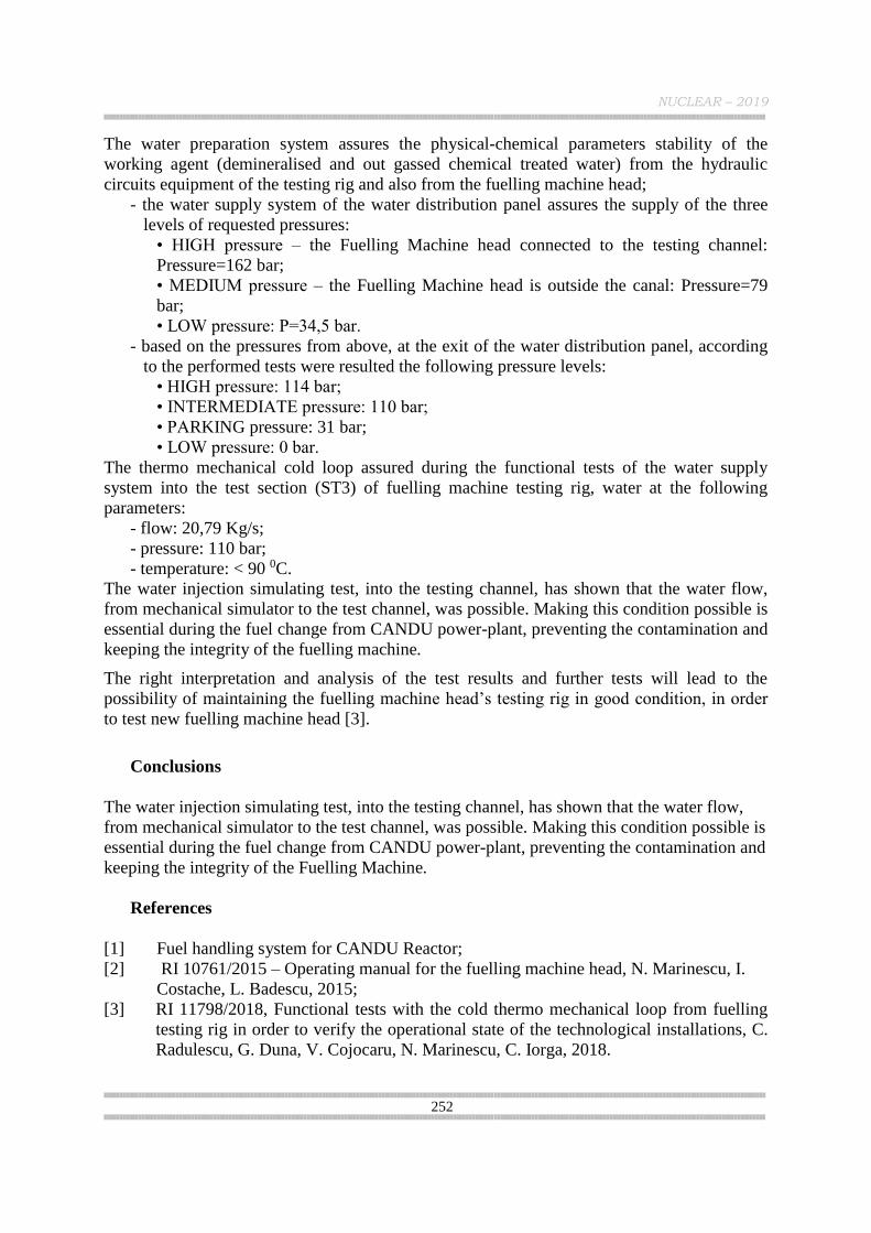
The water preparation system assures the physical-chemical parameters stability of the
working agent (demineralised and out gassed chemical treated water) from the hydraulic
circuits equipment of the testing rig and also from the fuelling machine head;
- the water supply system of the water distribution panel assures the supply of the three
levels of requested pressures:
• HIGH pressure – the Fuelling Machine head connected to the testing channel:
Pressure=162 bar;
• MEDIUM pressure – the Fuelling Machine head is outside the canal: Pressure=79
bar;
• LOW pressure: P=34,5 bar.
- based on the pressures from above, at the exit of the water distribution panel, according
to the performed tests were resulted the following pressure levels:
• HIGH pressure: 114 bar;
• INTERMEDIATE pressure: 110 bar;
• PARKING pressure: 31 bar;
• LOW pressure: 0 bar.
The thermo mechanical cold loop assured during the functional tests of the water supply
system into the test section (ST3) of fuelling machine testing rig, water at the following
parameters:
- flow: 20,79 Kg/s;
- pressure: 110 bar;
- temperature: < 90 0C.
The water injection simulating test, into the testing channel, has shown that the water flow,
from mechanical simulator to the test channel, was possible. Making this condition possible is
essential during the fuel change from CANDU power-plant, preventing the contamination and
keeping the integrity of the fuelling machine.
The right interpretation and analysis of the test results and further tests will lead to the
possibility of maintaining the fuelling machine head’s testing rig in good condition, in order
to test new fuelling machine head [3].
Conclusions
The water injection simulating test, into the testing channel, has shown that the water flow,
from mechanical simulator to the test channel, was possible. Making this condition possible is
essential during the fuel change from CANDU power-plant, preventing the contamination and
keeping the integrity of the Fuelling Machine.
References
[1] Fuel handling system for CANDU Reactor;
[2] RI 10761/2015 – Operating manual for the fuelling machine head, N. Marinescu, I.
Costache, L. Badescu, 2015;
[3] RI 11798/2018, Functional tests with the cold thermo mechanical loop from fuelling
testing rig in order to verify the operational state of the technological installations, C.
Radulescu, G. Duna, V. Cojocaru, N. Marinescu, C. Iorga, 2018.