The Water Boiling Test - pciaonline.org
52
The Water Boiling Test Version 4.1.2 Cookstove Emissions and Efficiency in a Controlled Laboratory Setting DRAFT – October 1, 2009 Version 4.1.2: Version for public comment Please return comments by December 1, 2009 Responses to comments from technical committee may be found at methods.bioenergylists.org Remaining needs: - Fill in web pages where data can be submitted - Describe fuel use benchmarks and critical equations (“Equivalent dry wood consumed” , “Effective mass of water boiled”, “Thermal efficiency” as in spreadsheet) - Alter equations—some are now pictures, which makes the Word document very large. Needs donated time from someone with equation skills.
Transcript of The Water Boiling Test - pciaonline.org

The Water Boiling Test Version 4.1.2
Cookstove Emissions and Efficiency in a Controlled Laboratory Setting
DRAFT – October 1, 2009 Version 4.1.2: Version for public comment Please return comments by December 1, 2009
Responses to comments from technical committee may be found at methods.bioenergylists.org
Remaining needs:
- Fill in web pages where data can be submitted - Describe fuel use benchmarks and critical equations (“Equivalent dry wood consumed” , “Effective mass of water boiled”, “Thermal efficiency” as in spreadsheet) - Alter equations—some are now pictures, which makes the Word document very large. Needs donated time from someone with equation skills.

Water Boiling Test, version 4.1.2 2
2
Table of Contents Introduction and Background .............................................................1 Benefits and limitations of the WBT.................................................1 Emission testing.........................................................................2 Interpretation of Water Boiling Test measures.....................................2 Document structure ....................................................................2 Preparing the Laboratory ..................................................................4 Preparing for Testing .......................................................................5 Testing a new stove ....................................................................5 Daily preparation .......................................................................5 Water Boiling Test Protocol................................................................7 Overview .................................................................................7 Emission testing.........................................................................8 Preparation for each set of 3 WBTs ..................................................8 Preparation for each WBT.............................................................9 WBT Phase 1: High power (cold start)...............................................9 WBT Phase 2: High power (hot start).............................................. 11 WBT Phase 3: Low power (simmering) ............................................ 12 Completion ................................................................................ 14 Appendix 1. Preparation for the Water Boiling Test................................. 15 1.1. Holding the thermocouple in the pot........................................ 15 1.2. Determining local boiling point............................................... 16 Appendix 2. Modifications to the Water Boiling Test................................ 18 2.1 Non-wood fuels................................................................... 18 2.2 Multi-pot stoves .................................................................. 19 Appendix 3. History of the Water Boiling Test ....................................... 21 Appendix 4. Calculations Used to Determine WBT Performance Metrics ........ 23 Appendix 5. Statistics Lessons for Performance Testing............................ 31 Appendix 6. Emission Measurement ................................................... 33 Which pollutants should be measured? ........................................... 33 Capturing the exhaust ............................................................... 33 Data collection........................................................................ 34 Pollutant measurements............................................................. 37 Data acquisition....................................................................... 41 Appendix 7. Data Entry Sheets ......................................................... 44 Appendix 8. Outstanding Issues with the WBT ....................................... 48

Water Boiling Test, version 4.1.2 1
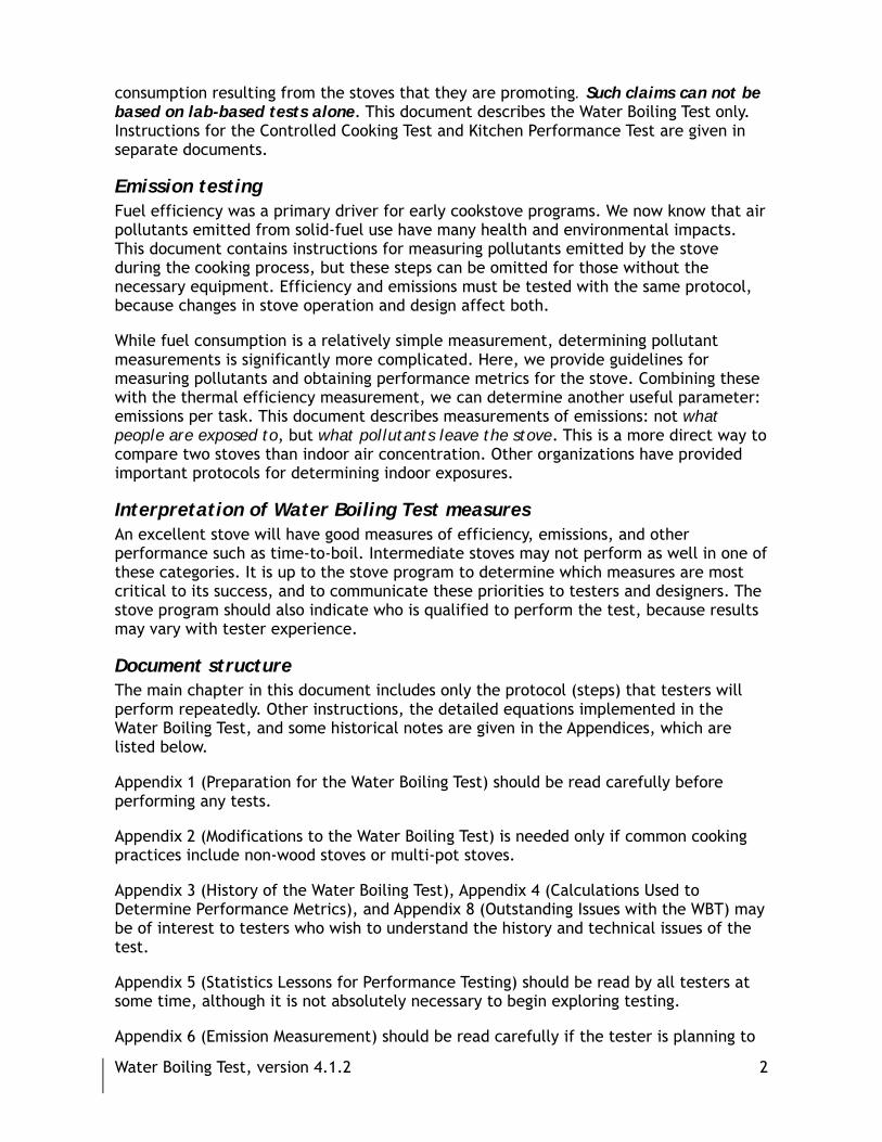
Introduction and Background The Water Boiling Test (WBT) is a simplified simulation of the cooking process. It is intended to help stove designers measure how efficiently a stove uses fuel to heat water in a cooking pot and the quantity of harmful emissions produced while cooking.
Benefits and limitations of the WBT The WBT test for efficiency can be performed throughout the world with simple equipment. (If emissions are measured, more complex equipment is required.) Its primary benefits are:
⇒ Provide an initial assessment of stove performance
⇒ Compare the effectiveness of different designs at performing similar tasks
⇒ Evaluate stove changes during development
⇒ Select the most promising products for field trials
⇒ Ensure that manufactured stoves meet design specifications
All standardized tests involve trade-offs. A test in which conditions are highly controlled conditions is better able to detect small changes due to design, because variability has been reduced. However, a more controlled test is often less representative of actual cooking. Controlled tests are appropriate at the early stages of stove development to compare various technical aspects of stove design. While lab-based tests allow stove developers to differentiate between well-designed and poorly-designed stoves, they give little indication of how the stoves are actually used.
The Water Boiling Test is the most controlled of three tests that were developed to assess stove performance, and thus it is probably the least like local cooking. Although the WBT is a useful tool for the reasons given above, it’s important to remember its limitations. It is only an approximation of the cooking process and is conducted in controlled conditions by trained technicians. Laboratory test results might differ from results obtained when cooking real foods with local fuels, even if efficiency and emissions were measured in exactly the same way for both tests. In order to confirm that stove projects are having the desired impact (whether it is fuel conservation, smoke reduction, or both), the stoves must be measured under real conditions of use.
To understand how stoves perform with local foods, cooking practices, and fuels, stove testers should use the Controlled Cooking Test (CCT) that has been developed in parallel with this test. The CCT is still a lab test. A Kitchen Performance Test (KPT), which compares fuel consumption in households using the improved stove to households using a traditional stove, should be conducted before drawing any conclusions about changes in fuel consumption among stove-users. The field test includes two qualitative surveys: the first helps project designers to assess household cooking practices prior to the introduction of the improved stove and the other provides them with follow-up data 3-6 months after the stove has been introduced to the family. The field test also includes a procedure to compare fuel consumption in households using different types of stoves. This test is critical if project designers wish to justify claims about real impacts on fuel
Water Boiling Test, version 4.1.2 2
consumption resulting from the stoves that they are promoting. Such claims can not be based on lab-based tests alone. This document describes the Water Boiling Test only. Instructions for the Controlled Cooking Test and Kitchen Performance Test are given in separate documents.
Emission testing Fuel efficiency was a primary driver for early cookstove programs. We now know that air pollutants emitted from solid-fuel use have many health and environmental impacts. This document contains instructions for measuring pollutants emitted by the stove during the cooking process, but these steps can be omitted for those without the necessary equipment. Efficiency and emissions must be tested with the same protocol, because changes in stove operation and design affect both.
While fuel consumption is a relatively simple measurement, determining pollutant measurements is significantly more complicated. Here, we provide guidelines for measuring pollutants and obtaining performance metrics for the stove. Combining these with the thermal efficiency measurement, we can determine another useful parameter: emissions per task. This document describes measurements of emissions: not what people are exposed to, but what pollutants leave the stove. This is a more direct way to compare two stoves than indoor air concentration. Other organizations have provided important protocols for determining indoor exposures.
Interpretation of Water Boiling Test measures An excellent stove will have good measures of efficiency, emissions, and other performance such as time-to-boil. Intermediate stoves may not perform as well in one of these categories. It is up to the stove program to determine which measures are most critical to its success, and to communicate these priorities to testers and designers. The stove program should also indicate who is qualified to perform the test, because results may vary with tester experience.
Document structure The main chapter in this document includes only the protocol (steps) that testers will perform repeatedly. Other instructions, the detailed equations implemented in the Water Boiling Test, and some historical notes are given in the Appendices, which are listed below.
Appendix 1 (Preparation for the Water Boiling Test) should be read carefully before performing any tests.
Appendix 2 (Modifications to the Water Boiling Test) is needed only if common cooking practices include non-wood stoves or multi-pot stoves.
Appendix 3 (History of the Water Boiling Test), Appendix 4 (Calculations Used to Determine Performance Metrics), and Appendix 8 (Outstanding Issues with the WBT) may be of interest to testers who wish to understand the history and technical issues of the test.
Appendix 5 (Statistics Lessons for Performance Testing) should be read by all testers at some time, although it is not absolutely necessary to begin exploring testing.
Appendix 6 (Emission Measurement) should be read carefully if the tester is planning to

Water Boiling Test, version 4.1.2 3
perform emission measurements.
Appendix 7 (Data Entry Forms) provides forms that can be printed for hand recording of data.
Appendix 8 (Outstanding Issues with the WBT) may be of interest to testers who wish to understand technical issues that remain to be resolved.
Water Boiling Test, version 4.1.2 4
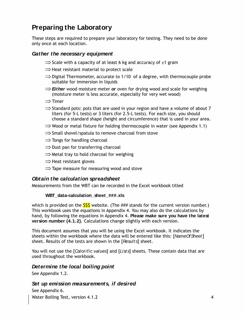
Preparing the Laboratory These steps are required to prepare your laboratory for testing. They need to be done only once at each location.
Gather the necessary equipment
⇒ Scale with a capacity of at least 6 kg and accuracy of ±1 gram
⇒ Heat resistant material to protect scale
⇒ Digital Thermometer, accurate to 1/10 of a degree, with thermocouple probe suitable for immersion in liquids
⇒ Either wood moisture meter or oven for drying wood and scale for weighing (moisture meter is less accurate, especially for very wet wood)
⇒ Timer
⇒ Standard pots: pots that are used in your region and have a volume of about 7 liters (for 5-L tests) or 3 liters (for 2.5-L tests). For each size, you should choose a standard shape (height and circumference) that is used in your area.
⇒ Wood or metal fixture for holding thermocouple in water (see Appendix 1.1)
⇒ Small shovel/spatula to remove charcoal from stove
⇒ Tongs for handling charcoal
⇒ Dust pan for transferring charcoal
⇒ Metal tray to hold charcoal for weighing
⇒ Heat resistant gloves
⇒ Tape measure for measuring wood and stove
Obtain the calculation spreadsheet Measurements from the WBT can be recorded in the Excel workbook titled
WBT_data-calculation_sheet_###.xls
which is provided on the $$$ website. (The ### stands for the current version number.) This workbook uses the equations in Appendix 4. You may also do the calculations by hand, by following the equations in Appendix 4. Please make sure you have the latest version number (4.1.2). Calculations change slightly with each version.
This document assumes that you will be using the Excel workbook. It indicates the sheets within the workbook where the data will be entered like this: [NameOfSheet] sheet. Results of the tests are shown in the [Results] sheet.
You will not use the [Calorific values] and [Lists] sheets. These contain data that are used throughout the workbook.
Determine the local boiling point See Appendix 1.2.
Set up emission measurements, if desired See Appendix 6.

Water Boiling Test, version 4.1.2 5
Preparing for Testing
The cooking system includes a stove, a fuel, a pot, and an operator.
All four affect the performance of the system. You should use the same fuel and pot for each test if you wish to compare design changes. However, you should never use a
fuel or pot for which a stove was not designed.
Testing a New Stove
1) Perform at least one practice test on each type of stove in order to become familiar with the testing procedure and with the characteristics of the stove. This will provide an indication of how much fuel is required to boil the required amount of water.
2) The operation of the stove has a large effect on the outcome of stove performance tests. All tests of a single stove, and all tests to evaluate design improvements, must be done with consistent operation of the stove. Document the operation with written procedures, photos, or videos (if possible).
3) Determine the type and characteristics of fuel you will use. The type, size and moisture content of fuel has a large effect on the outcome of stove performance tests. For that reason, all tests of a single stove, or all tests to evaluate design improvements, must be done with fuel of the same type and moisture content, and similar size. For raw biomass, fuel that has been thoroughly air dried is preferable. Remember that wood of 3-4 cm in diameter may take from 3-8 months to dry fully, although dung or crop residues may take less time. Drying can be accelerated by circulating air through stored wood. Document the fuel type, moisture content, and size.
4) Determine the type of pot you will use, and record its size and shape. The 7-liter pot should be used unless the stove is designed for a much smaller pot and cannot boil 5 liters of water, or the stove is designed for a specific pot.
Daily Preparation
Preparation for each day’s testing may be done the previous day to save time.
1) Find your space. Make sure that there is adequate space and sufficient time to conduct the test without being disturbed. Testing should be done indoors in a room that is protected from wind, but with sufficient ventilation to vent harmful stove emissions. Wind or air draft changes heat transfer between the stove and the pot and will affect the results of the test, and must be avoided. It will take 1½ - 2 hours to do the high and low power test for each stove.
2) Prepare fuel. Prepare enough bundles of fuel to conduct several tests before starting the first test. Obtain all of the fuel from the same source if possible. Solid fuel should be well dried and uniform in size. At least 5 kg of air-dried fuel will be needed for each test (15 kg to test the stove three times). More fuel may be needed for high mass stoves. If kindling will be used to start the fire, it should be prepared ahead of time and included in the pre-weighed bundles of fuel.

Water Boiling Test, version 4.1.2 6
3) Prepare water. One full WBT requires at least 10 liters of water at ambient temperature for each pot being used. If water is scarce in your area, water used one day may be cooled and reused in the next day’s testing. Do not start any tests with water that is much hotter than room temperature.
4) Determine moisture content of the fuel to be used during testing. See the guidelines in Appendix 1.2.

Water Boiling Test, version 4.1.2 7
Water Boiling Test Protocol
The entire WBT should be conducted three times for each stove.
The tester should never perform a task that is unsafe. No test should require the stove to perform a task that would not
occur during its normal operation.
Overview
The WBT consists of three phases that immediately follow each other. These are discussed below and shown graphically in Figure 1.
1) For the cold-start high-power test, the tester begins with the stove at room temperature and uses a pre-weighed bundle of fuel1 to boil a measured quantity of water in a standard pot. The tester then replaces the boiled water with a fresh pot of ambient-temperature water to perform the second phase of the test.
2) The hot-start high-power test is conducted after the first test while stove is still hot. Again, the tester uses a pre-weighed bundle of fuel to boil a measured quantity of water in a standard pot. Repeating the test with a hot stove helps to identify differences in performance between a stove when it is cold and when it is hot. This is particularly important for stoves with high thermal mass, since these stoves may be kept warm in practice.
3) The simmer test provides the amount of fuel required to simmer a measured amount of water at just below boiling point for 45 minutes. This step simulates the long cooking of legumes or pulses common throughout much of the world.
Time
WaterTemperature
Tboil
Troom
Tboil-6degC
Fresh Water
COLD START 45 min. SIMMERHOT START
Figure 1. Temperature during the three phases of the water boiling test. (Figure credit: Nordica MacCarty)
These three phases simulate common cooking processes (boiling and simmering) to
1 This test was originally designed for stoves that burn wood, but has been adapted to accommodate other types of stoves and fuels. See Appendix 2 for a discussion of the use of non-woody fuels.

Water Boiling Test, version 4.1.2 8
obtain approximate stove performance metrics according to the equations in Appendix 4 and 6. The metrics provided by the WBT are:
⇒ time to boil ;
⇒ burning rate ;
⇒ specific fuel consumption ;
⇒ firepower
⇒ turn-down ratio (ratio of the stove’s high power output to its low power output);
⇒ thermal efficiency (for high power tests only)
⇒ emissions per fuel burned
⇒ emissions per task (water boiled or heat generated)
⇒ combustion efficiency (fraction of fuel burned completely)
While an excellent stove will perform well in all metrics, it is up to the stove program to determine which measures are most critical to its success, and to communicate this to testers and designers.
Emission testing
This basic testing protocol includes Instructions for measuring carbon monoxide (CO), particulate matter (PM), and carbon dioxide (CO2) concentrations in the stove’s exhaust. You may also choose to measure other pollutants.
There are many ways to measure PM. For real-time measurements, the instruction “Begin emission measurement” means “Begin recording the particulate matter measurement.” For filter-based measurements, the same instruction means “Turn on flow to the particulate matter filter.” Both CO and CO2 are measured in real-time, so the instruction means “Begin recording the emission measurement.” Likewise, “End emission measurement” means “Stop recording the emission measurement” or “Turn off flow to the particulate matter filter.”
Preparation for each set of 3 Water Boiling Tests
1) Create a new Excel data sheet for each series of tests by making a copy of “WBT_data-calculation_sheet_###.xls”, where the ### stands for the version number. Tests should always have a unique name or code number. You, the user, should fill out all gray cells and cells with listboxes (choices). Other cells are calculations.
2) Fill out the [General Information] sheet. A copy of this sheet is given in Appendix 7 if you wish to fill it out by hand. This sheet asks you to:
⇒ identify the testers and assign a test number
⇒ describe the stove*
⇒ measure and record the ambient conditions; do not proceed if wind will affect your testing location
⇒ record the local boiling point of water (determined using Appendix 1.2)
Water Boiling Test, version 4.1.2 9
⇒ weigh the dry pots without lid and the char container
⇒ describe the fuel**
⇒ enter the calorific value of the fuel **
⇒ describe the operation of the stove, especially fuel addition, during the high-power and simmering tests (you should know this from your practice tests)
* Guidance for stove description: Photograph the stove, if possible. Use a tape measure to record the dimensions of the stove. Identify the materials used for stove construction. Use an additional sheet if necessary.
** Guidance for fuel description: give your own description of the fuel, and record the fuel dimensions. Also, record the material you will use for ignition. You may obtain a calorific value of the fuel either from your own measurement, or by choosing a type of fuel from the list in the spreadsheet.
3) Fill out the [Fuel Moisture] sheet if you are using a handheld moisture meter. A copy of this sheet is given in Appendix 7 if you wish to fill it out by hand, but you will need to enter the values in the worksheet to obtain the calculated moisture content.
4) Determine whether your fuel is fed continuously or in a batch. Many wood and crop waste stoves are continuous feed, while most charcoal and liquid-fuel stoves are loaded with fuel before the test. The test for batch-fed stoves is slightly easier because the form of the fuel does not change during the test (for example, wood changing to charcoal). The two types of fuel-feeding have some separate instructions.
Preparation for each Water Boiling Test
1) Prepare a Test Entry form. If you wish to record data by hand at first, print a Test Entry Sheet from the Excel workbook or from Appendix 7. If you wish to record the data directly in the workbook, choose the [Test-1], [Test-2] or [Test-3] sheet.
2) Measure and record the ambient conditions.
3) If testing emissions: Record ambient CO2, CO, and particulate matter concentrations.
Fuel description and calorific value is no longer entered on the Test Entry sheets, but is taken from the [General Information] sheet. The same fuel type, size, and moisture content must be used for the three replicates of the WBT.
WBT Phase 1: High Power (Cold Start) Data recorded in the remaining phases of the test should be recorded on the Test Entry form. The stove should begin at room temperature.
1. Prepare the timer (do not start it yet).
2. Continuous: Record the weight of the bundle of fuel plus kindling in the Test Entry Form. Batch (Includes charcoal, ethanol, kerosene, and LPG): Weigh the stove loaded with fuel. Enter the weight of the fuel plus stove in the space for “Weight of wood.”
3. Fill each pot with 5 kg (5 liters) of clean room temperature water (if using the
Water Boiling Test, version 4.1.2 10
smaller standard pot, fill the pot with 2.5 kg or 2.5 liters of water). The amount of water should be determined by placing the pot on the scale and adding water until the total weight of pot and water together is 5 kg (or 2.5 kg) more than the weight of the pot alone. Record the weight of pot and water in the Test Entry form.
(If the stove cannot accommodate the standard pot and the pot that is used cannot accommodate 5 (or 2.5) kg of water, OR if a multi-pot stove is used with non-standard pots that cannot accommodate 5 (or 2.5) kg of water, fill each pot about 2/3 full and record the change in procedure in the comment space. Record the weight of the pot(s) with the water on the Test Entry Form. Use the same amount of water for each test.)
4. Using the wooden fixtures, place a thermometer in each pot so that water temperature may be measured in the center, 5 cm from the bottom. If there are additional pots, use the additional thermometers if possible. Record the initial water temperature in each pot and confirm that it does not vary substantially from the ambient temperature.
Note: There should NOT be a lid on the pot while conducting the WBT.2
5. Begin emission measurement (If time, temperature, and emissions are recorded in one device, just press the “start” button.)
6. Start the fire in a reproducible manner according to local practices. Record any starting materials that are used other than the fuel from the first pre-measured bundle (e.g. paper or kerosene). (This procedure should be documented.)
7. Once the fire has caught, start the timer and record the starting time. Throughout the following “high power” phase of the test, control the fire with the means commonly used locally to bring the first pot rapidly to a boil without being excessively wasteful of fuel. (This procedure should be documented.)
8. When the water in the first pot reaches the pre-determined local boiling temperature as shown by the digital thermometer, rapidly do the following:
a. Record the time at which the water in the primary pot (Pot # 1) first reaches the local boiling temperature. Record this temperature also.
b. End emission measurement.
c. Continuous: Remove all wood from the stove and extinguish the flames. Flames can be extinguished by blowing on the ends of the sticks or placing them in a bucket of ash or sand; do not use water – it will affect the weight of the wood. Knock all loose charcoal from the ends of the wood into the container for weighing charcoal. (This procedure is not included in the emission measurement because it is not part of normal operation.)
d. Continuous: Weigh the unburned wood removed from the stove together with the remaining wood from the pre-weighed bundle. Record the weight on the Test Entry form in the “Weight of Wood” location.
2 While a lid helps to retain heat in the pot, and is often used for any actual cooking task, it does not affect the transfer of heat from the stove to the pot. Lids complicate the WBT by increasing the variability of the outcome and making it harder to compare results from different tests.

Water Boiling Test, version 4.1.2 11
e. Continuous: Extract all remaining charcoal from the stove, place it with the charcoal that was knocked off the sticks and weigh it all. Record the weight of the charcoal + container on the Test Entry Form.
f. Batch: Weigh the loaded stove plus fuel and record that weight in the “Weight of wood” location. Record zero for the weight of charcoal.
g. For multi-pot stoves, measure the water temperature from each pot (the primary pot should be at the boiling point). Record the temperatures on the Test Entry Form.
h. Weigh each pot, with its water. Record these weights on the Data and Calculation form.
i. Discard the hot water.
9. Record the following information on the Test Entry Form:
⇒ Time and temperature of the boiling water in the first pot
⇒ Weight of each pot with the remaining water
⇒ Multi-pot stoves only: Temperature that each additional pot reached when Pot # 1 first came to its full boiling temperature.
This completes the high power cold-start phase. Next, begin the high power-hot start test, immediately while the stove is still hot. Be careful not to burn yourself!
WBT Phase 2: High Power (Hot Start) 1. Reset the timer (do not start it yet).
2. Refill the pot with 5 (or 2.5) kg of fresh ambient-temperature water. Weigh the pot (with water) and measure the initial water temperature and; record both measurements on the Test Entry sheet. For multi-pot stoves, fill the additional pots, weigh them and record their weights.
3. Continuous: Record the weight of the second bundle of fuel plus kindling in the Test Entry Form. Batch: Weigh the stove loaded with fuel. Enter the weight of the fuel plus stove in the space for “Weight of wood.”
4. Begin emission measurement.
5. Light the fire using fuel from the second pre-weighed bundle designated for this phase of the test. Follow the ignition procedure used in the first phase.
6. When the fire has caught, start the timer.
7. Record the starting time, and bring the first pot rapidly to a boil without being excessively wasteful of fuel using wood from the second pre-weighed bundle.
8. Record the time at which the first pot reaches the local boiling point as indicated on the Test Entry form.
9. After reaching the boiling temperature, quickly do the following. Speed (and safety) are important at this stage because the water temperature should stay as close as possible to boiling in order to allow us to proceed directly to the simmer test. The pot of hot water may be temporarily covered with a lid and placed on a hot plate (if available) to keep the water temperature close to boiling during the following steps

Water Boiling Test, version 4.1.2 12
a, b, and c.
a. End emission measurement.
b. Continuous: Remove the unburned wood from the stove. Knock off any loose charcoal, but try to keep it in the combustion area (you will not weigh the charcoal at this stage). Weigh the wood removed from the stove, together with the unused wood from the previously weighed supply. Record result on Test Entry form in the “Weight of wood” location.
c. Batch: Weigh the loaded stove plus fuel and record that weight in the “Weight of wood” location. Record zero for the weight of charcoal.
d. Measure and record the water temperature from other pots if more than one pot is used.
e. Weigh each pot and record its weight on the Test Entry Form. After weighing, immediately replace each pot on the stove.
10. Be sure you have recorded the following information on the Test Entry Form:
⇒ Time at which the first pot reaches local boiling point
⇒ Amount of wood remaining
⇒ Weight of each pot with the remaining water
⇒ Multi-pot stoves only: Temperature from other pots
11. Replace the wood removed from the fire. Proceed immediately with the low power test.
WBT Phase 3: Low Power (Simmering) This portion of the test is designed to test the ability of the stove to shift into a low power phase following a high-power phase in order to simmer water for 45 minutes using a minimal amount of fuel. For multi-pot stoves, only the primary pot will be assessed for simmering performance (see the discussion of multi-pot stove-testing in Appendix 2).
1. Start emission measurement.
2. Relight the hot wood that was replaced. Follow the ignition procedure used in Phase 1.
3. Reset and start the timer.
4. Replace the thermometer in the pot. Adjust the fire to keep the water as close to 3 degrees below the established boiling point as possible.
5. For 45 minutes maintain the fire at a level that keeps the water temperature as close as possible to 3 degrees below the boiling point.

Water Boiling Test, version 4.1.2 13
It is acceptable if temperatures vary, but:
⇒ The tester must try to keep the simmering water as close as possible to 3 degrees C below the local boiling point.3
⇒ The test is invalid if the temperature in the pot drops more than 6°C below the local boiling temperature.
6. After 45 minutes rapidly do the following:
a. End emission measurement.
b. Record the final water temperature on Test Entry Form – it should still be about 3 °C below the established boiling point.
c. Continuous: Remove all wood from the stove and knock any loose charcoal into the charcoal container. Record the weight of this wood, plus any remaining from the bundle of fuel, in the Test Entry Form.
d. Continuous: Extract all remaining charcoal from the stove and weigh it (including charcoal which was knocked off the sticks). Record the weight of pan plus charcoal.
e. Batch: Weigh the stove loaded with fuel. Enter the weight of the fuel plus stove on the Test Entry Form in the space for “Weight of wood.”
f. Weigh the pot with the remaining water.
7. Be sure you have recorded the following information on the Test Entry Form:
⇒ Finish time of test
⇒ Weight of wood removed from stove AND in the pre-weighed bundle
⇒ Weight of pan plus charcoal
⇒ Final water temperature
⇒ Weight of pot with remaining water
⇒ Ambient air temperature and humidity
⇒ Weight of container to be used for charcoal
⇒ Local boiling point of water (determined at your location according to Appendix 1.2)
⇒ If testing emissions: Ambient CO2, CO, and particulate matter concentrations
3 Many stoves lack adequate turndown ability. The tester may find that it is impossible to maintain the desired temperature without the fire going out (especially after the initial load of charcoal in the stove has been consumed). If this is the case, the tester should use the minimum amount of wood necessary to keep the fire from dying completely. Water temperatures in this case will be higher than 3° below boiling, but the test is still valid. The tester should not attempt to reduce power by splitting the wood into smaller pieces.

Water Boiling Test, version 4.1.2 14
Changes to Testing Conditions to Improve Repeatability
The WBT is designed to test many stoves in many places, but comparisons become less reliable as testing conditions vary. You should identify the reasons for testing when deciding on the form of the test. If you are using the WBT as a preliminary measure of stove performance during the design phase, then adapt the protocol to local conditions. Academic laboratories may be using tests to compare the performance of their stoves with other available stove models. In these situations, some changes may be made to the test to improve repeatability. However, we caution that these changes may make the stove perform differently than it would in practice. If laboratory tests are very different from real operation, then comparisons done in the laboratory may lead to incorrect conclusions about stoves in real operation. Any specific changes to the WBT should be noted in the documentation for each test.
It is the tester’s responsibility to ensure that stove operation after these changes, or any other changes implemented to reduce variability,
is just as representative of field conditions as the standard protocol.
1. Fuel
a. Type: Wood with high heat content (between 20-21 MJ/kg), and without excessive pitch content, should be used for all tests. Choose one wood which is used widely in the region.
b. Dimensions: Different sizes of solid fuels have different burning characteristics. Some laboratories have used wood with cross-sectional dimensions of 1.5 cm x 1.5 cm.
c. Moisture content: All testing should be carried out with wood of low moisture content (values used have been 6.5% or 10% on a wet basis). This reduces variability but may make combustion unlike field conditions.
2. Initial Water Temperature: A fixed initial temperature can be chosen for the water rather than relying on ambient temperature (15 C has been used).4
3. Cooking Pot: The tests should be conducted with either a large standard pot (with a 7 liter capacity) or a small standard pot (with a 3.5 liter capacity), depending on the size of the stove.
Completion The three phases described above complete the WBT. Be sure that you have entered all the data required.
Once you have completed the test and entered the data, the workbook can be uploaded to the $$$ website. Sharing data about testing around the world helps the stove community to understand what stoves, interventions and design options are the best solutions. Please be sure that your sponsors are comfortable with sharing the data.
4 The temperature-corrected time to boil and specific consumption should still use a reference temperature of 25 C for comparability with other tests.

Water Boiling Test, version 4.1.2 15
Appendix 1. Preparation for the Water Boiling Test This appendix provides guidance on initial setup of the equipment for the Water Boiling Test. It also discusses two methods that are needed to perform the WBT, local boiling point and fuel moisture content.
1.1 Holding the Thermocouple in the Pot The diagram below shows a wooden fixture holding thermocouple (TC) probe in the pot. The dimensions are not critical, but the fixture should be made so that the TC probe fits into it tightly and the fixture itself fits securely on the pot.
Wooden probeholder
TC probeTC probe wire (leading to digital thermometer)
Standard pot (large or small)
~5 cm
Side view
Top view
Hole drilled in center offixture (diameter shouldbe just large enough to
fit TC probe tightly
Hole drilled in center offixture (diameter shouldbe just large enough to
fit TC probe tightly
Bottom view
Slots are cut out to tightly accommodate
pot rim.

Water Boiling Test, version 4.1.2 16
1.2 Determining Local Boiling Point The local boiling point of water is the point at which the temperature no longer rises, no matter how much heat is applied. The local boiling temperature is influenced by several factors including altitude, minor inaccuracies in the thermometer, and weather conditions. For these reasons, the local boiling temperature cannot be assumed to be 100° C. For a given altitude h (in meters), the boiling point of water may be estimated by the following formula:
ChTbo⎟⎠
⎞⎜⎝
⎛ −=300
100
However, it is better to determine the local boiling point empirically using the following procedure:
1) Choose whether you will use the large or small standard pot. Measure 5 liters of water for the large standard pot (or 2.5 liters for the small standard pot). Bring it to a rolling boil. Make sure that the stove’s power output is high, and the water is fully boiling!
2) Using the same thermometer that will be used for testing, measure the boiling temperature when the thermometer is positioned in the center, 5 cm above the pot bottom. You may find that even at full boil, when the temperature no longer increases, it will still oscillate several tenths of a degree above and below the actual boiling point.
3) Record the temperature over a five minute period at full boil and note the maximum and minimum temperatures observed during this period. The maximum and minimum temperatures should then be averaged. This result will be recorded as the “local boiling temperature” on the [General Information] sheet in the Excel work book whenever you do a test.
1.3 Determining Fuel Moisture Content Well-dried fuel contains 10-20% water while fresh cut wood may contain more than 50% water by mass (wet basis). Ideally, fuel used for both testing stoves and for cooking by project beneficiaries should be dried as much as local environmental conditions allow. However, dried fuel is not always available and both stove testers and household cooks must use what they can get. In order to control for variations in fuel moisture content, stove testers should measure it and account for it in their stove performance calculations. Thus, you need to input moisture content in the [Fuel Moisture] sheet within the workbook.
There are two ways of defining fuel moisture content: on a wet basis and on a dry basis. In the former, the mass of water in the fuel is reported as a percentage of the mass of wet fuel and in the latter case, it is reported as a percentage of the mass of the dry fuel. The calculations for each are shown below followed by a plot showing how both wood moisture on a wet basis and wood mass vary with wood moisture defined on a dry basis for one kg of oven-dry wood. Unless otherwise specified, we will report wood moisture on a wet basis. The testers should always specify which basis they are using.

Water Boiling Test, version 4.1.2 17
The two moisture contents are related in this way:
dry
drywet MC
MCMC
+=
1
Measuring moisture content can be done in two ways. The most precise way is to use the equations listed above by weighing a sample of the air-dry fuel (Mass of fuel)wet and weighing it again after it has been completely dried (Mass of fuel)dry. Take a small sample (200-300 g) of the fuel randomly from the stock of fuel to be used for the tests. Weigh the sample and record the mass. Dry the sample an oven at a few degrees over 100 °C and weigh it again. This may be done at the testing site if an oven is available, or the wet sample may be weighed on-site and then stored carefully and dried later, when an oven is available.
To dry the sample, put it in an oven overnight and then remove it and weigh the sample every two hours on a sensitive scale (±1 g accuracy) until the mass no longer decreases. The oven temperature should be carefully controlled so that it doesn’t exceed 110°C (230°F). If the wood is exposed to temperatures near 200°C (390°F), it will thermally break down and lose matter that is not water, causing an inaccurate measurement of moisture content.
A second way to measure wood moisture is with a wood moisture meter. This device measures fuel moisture on a dry basis by measuring the conductivity between two sharp probes that are inserted in the wood. This is more convenient than oven-drying because the measurement can be rapidly done on site as the fuel is being prepared. The probes should be inserted parallel with the grain of the wood. The device may be adjusted for different species and calibrated for different ambient temperatures. The meter measures between 6% and 35-40% moisture (dry basis). If the sample of wood is wetter than the upper range of the meter, the meter will either show an error. Wood moisture can vary in a given piece of wood as well as among different pieces from a given bundle. When the meter is used, take three pieces of wood randomly from the bundle and measure each piece in three places. This yields nine measurements overall. The moisture of the bundle should be reported as the average of these nine measurements. Convert this average to a wet basis using the formula (this is done automatically in the computer spreadsheet). Record this average in the [Fuel Moisture] sheet.
Note – the moisture meter is not designed to measure non-woody fuels and should not be used on dung or crop residues. If dung or crop residues are used, then the oven-drying method is recommended. See Appendix 2 for further discussion.
Water Boiling Test, version 4.1.2 18
Appendix 2. Modifications to the Water Boiling Test
2.1 Non-Wood Fuels This WBT may be done with many different stove-fuel combinations, including stoves that burn liquid and gaseous fuels, as well as solid fuels like coal, charcoal, crop residues and dung. However, if fuels other than wood are used then there are some special factors to consider when filling the data entry and calculation forms. These are discussed below for each fuel.
Liquid and gaseous fuels
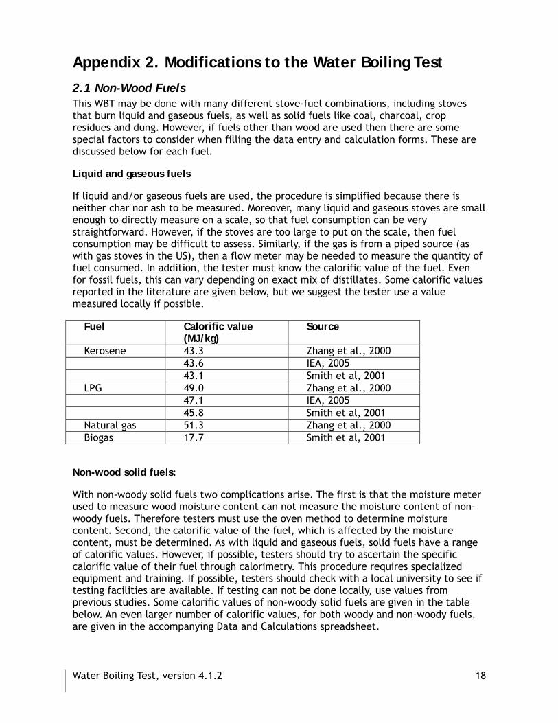
If liquid and/or gaseous fuels are used, the procedure is simplified because there is neither char nor ash to be measured. Moreover, many liquid and gaseous stoves are small enough to directly measure on a scale, so that fuel consumption can be very straightforward. However, if the stoves are too large to put on the scale, then fuel consumption may be difficult to assess. Similarly, if the gas is from a piped source (as with gas stoves in the US), then a flow meter may be needed to measure the quantity of fuel consumed. In addition, the tester must know the calorific value of the fuel. Even for fossil fuels, this can vary depending on exact mix of distillates. Some calorific values reported in the literature are given below, but we suggest the tester use a value measured locally if possible.
Fuel Calorific value (MJ/kg)
Source
Kerosene 43.3 Zhang et al., 2000 43.6 IEA, 2005 43.1 Smith et al, 2001 LPG 49.0 Zhang et al., 2000 47.1 IEA, 2005 45.8 Smith et al, 2001 Natural gas 51.3 Zhang et al., 2000 Biogas 17.7 Smith et al, 2001
Non-wood solid fuels:
With non-woody solid fuels two complications arise. The first is that the moisture meter used to measure wood moisture content can not measure the moisture content of non-woody fuels. Therefore testers must use the oven method to determine moisture content. Second, the calorific value of the fuel, which is affected by the moisture content, must be determined. As with liquid and gaseous fuels, solid fuels have a range of calorific values. However, if possible, testers should try to ascertain the specific calorific value of their fuel through calorimetry. This procedure requires specialized equipment and training. If possible, testers should check with a local university to see if testing facilities are available. If testing can not be done locally, use values from previous studies. Some calorific values of non-woody solid fuels are given in the table below. An even larger number of calorific values, for both woody and non-woody fuels, are given in the accompanying Data and Calculations spreadsheet.

Water Boiling Test, version 4.1.2 19
Fuel Calorific value (MJ/kg) Source Charcoal 25.7 @ 1.7 % MCwet Smith et al, 2001 27.6-31.5 @ ~5 % MCwet Pennise et al. 2002 Maize stalks 16.1 @ 9.1 % MCwet Zhang et al., 2000 15.4 @ 5.0 % MCwet RWEDP, 1993 Wheat stalks 14.0 @ 7.3 % MCwet Zhang et al., 2000 15.4 @ 5.0 % MCwet RWEDP, 1993 Rice stalks 13.0 @ 8.8 % MCwet Smith et al, 2001 14.2 @ 5.0 % MCwet RWEDP, 1993 Dung 11.8 @ 7.3 % MCwet Smith et al, 2001 15.4 @ 5.0 % MCwet RWEDP, 1993 Coal China 22.5 IEA, 2005 China 27.3 @ 2.1 % MCwet Zhang et al., 2000 China (washed) 30.1 @ 4.7 % MCwet Zhang et al., 2000 US 26.2 IEA, 2005 India 18.4 IEA, 2005 South Africa 23.5 IEA, 2005
2.2 Multi-pot stoves Some stoves are designed to cook with more than one pot. If this is the case, the tester should use the number of pots that the stove can accommodate (the testing forms have space for up to four pots). The explicit calculations for multiple pots are explained below.
High-power tests In order to closely mirror the single pot test and ensure that the task can be completed in a reasonable amount of time, the high power tests are stopped when the primary pot (the pot closest to the source of heat) comes to a boil. The indicators of stove performance account for the water heated in the additional pots. To do so they are modified in the following way.
Calculations that are modified to account for multiple pots in the high power tests*
fcm Wood consumed, moist (grams) Same as for single-pot stove
�cc Net change in char during test phase (grams) Same as for single-pot stove
fcd Equivalent dry wood consumed (grams) Same as for single-pot stove
wcv Water vaporized (grams) ( )∑=
−=4
1jccicvPPw
wcr “Boiled” water remaining at end of test (grams)
( )∑=
⎟⎟⎠
⎞⎜⎜⎝
⎛⎟⎟⎠
⎞⎜⎜⎝
⎛−−
∗−=4
1j cib
cicfcfcr TjT
TjTjPjPjw
�tc Duration of phase (min) Same as for single-pot stove
hc Thermal efficiency ( ) ( ) ( )
HVLf
w2260TjTjPjPj4.186h
cd
cvj
cicfci
c ∗
∗+⎥⎥⎦
⎤
⎢⎢⎣
⎡−∗−∗
=∑=
4
1

Water Boiling Test, version 4.1.2 20
rcb Burning rate (grams/min) Same as for single-pot stove
SCc Specific fuel consumption (grams wood/grams water) ( )∑
= ⎥⎥⎦
⎤
⎢⎢⎣
⎡⎟⎟⎠
⎞⎜⎜⎝
⎛−−
∗−
=4
1j cib
cicfcf
cdc
TjTTjTjPjPj
fSC
SCTc
Temp-corrected specific consumption (grams wood/grams water) cc
ccT
TTSSC−∗=7
FPc Firepower (W) Same as for single-pot stove
* These calculations use the subscript-c for the cold-start test, however the modified hot-start calculations are identical. In each case, j is an index of each pot (1-4)
The factor ⎟⎟⎠
⎞⎜⎜⎝
⎛−−
cib
cicf
TjTTjTj
is used to “discount” the water heated in additional pots that
does not come to a full boil. For example, when calculating specific consumption, which, in this test, measures the amount of wood required to boil a unit amount of water, we want to give credit for the water heated in other pots, although it was not boiled. Since the energy (Q) required to bring water to a
boil is a roughly linear function of the temperature change ( )TQ ∆∝ we discount the water that was not boiled by a factor that varies between zero and one, reflecting the fraction of sensible heat absorbed by the water relative to the heat required to boil it.
Low-power test In the low power test it is more difficult to incorporate the output from additional cooking pots. For this reason, multi-pot stoves may appear to be at a disadvantage in this part of the test, which assesses the ability of the stove to maintain a pot of water just below the boiling temperature. In lowering the power delivered to the primary cooking pot, the stove will probably not be able to deliver much heat to secondary pots. Fluctuations in temperature in the other pots will greatly complicate the assessment, thus they will be ignored. The Stove Performance Test used in assessing improved stoves in China adopts a similar procedure [10].
Of course, well-designed multi-pot stoves have the strength of providing high power to the primary cooking pot, while simultaneously providing low power to an additional pot (or pots). However, this test is designed to only bring the water in the primary pot to boiling temperatures and the stove performance indicators calculated from the results of the simmer test will only rely on the measurements taken from the primary pot. While this may not capture all of the strengths of the multi-pot stove, those strengths should be captured in the results of the high power test, as well as in the controlled cooking test and kitchen performance (field) tests, which also must be conducted to fully assess stove performance.
Water Boiling Test, version 4.1.2 21
Appendix 3. History of the Water Boiling Test The version numbers given in this discussion were assigned by the authors of the appendix. They were not assigned by the original authors (just like the first World War was never numbered until a second occurred). Version numbering should continue through the remaining course of the WBT.
Versions 1 and 2: Volunteers in Technical Assistance (VITA), 1982-1985 provided the first committee-based recommendations for testing cooking stoves. The document outlined three tests: the Water Boiling Test, the Controlled Cooking Test, and the Kitchen Performance Test. It was first published in 1982 and revised in 1985.
VITA struggled with all of the questions we faced in developing the current document. The introduction to this document recommends: “The standard should represent a compromise between the widest possible range of applications, and the closest possible fit with actual cooking practices.” They also pointed out the difference between testing “done for local use only (for stove users and others) and testing where the results are intended to be transmitted to other places.”
A revision of the WBT and a lot of perspective were provided by Dr. Samuel Baldwin in his book, “Biomass stoves: Engineering design, development, and dissemination.”
Version 3: UC Berkeley and Aprovecho, 2003-2007, often known as the “UCB WBT”. Rob Bailis, Damon Ogle, Nordica MacCarty, and Dean Still (this was also distributed as Version 1.5 on the Berkeley site).
The Shell Foundation began an entrée into the stoves world around 2001, and noticed the need for benchmarks because many “improved” stoves didn’t work. They engaged Dr. Kirk Smith, of UC Berkeley, to update the WBT and includes the CCT and KPT. Dr. Smith engaged Rob Bailis (then a graduate student) and Aprovecho personnel to revise the WBT.
During this process, Dean Still and Damon Ogle of Aprovecho performed a literature review and examined national tests, including those of China and India. They contacted field organizations who were conducting stove projects to ask about typical pot sizes, water amounts, and simmering times. This was the source of the recommended 5 liters and the simmering length. The resulting WBT incorporated procedures that were perceived to be the best available. Over about a year, the WBT equations were completely rewritten and developed into a spreadsheet, first by Rob Bailis, then with input from Dean Still and Damon Ogle, and finally maintained by Nordica MacCarty. Several other people provided critiques of the spreadsheet and equations.
An eye-opening experience occurred at Aprovecho’s 2005 “Stove Camp”: none of six testing teams at this camp was completely successful in implementing the written protocol. This did not bode well for field testing. During subsequent training and testing around the world, particularly by Nordica MacCarty, small modifications to both the WBT protocol and spreadsheet to improve user-friendliness were implemented.
Version 4: ETHOS (2007-2009). Around 2007, it became apparent that wider community involvement in testing methods was needed. Both the method of testing and some of the calculations in the WBT had been critiqued, and the “right” answer was not always apparent. University laboratories began seeking precision and repeatability, sometimes
Water Boiling Test, version 4.1.2 22
producing recommendations for changes to the test that were quite possible in laboratory settings but not practical for field testing. The group Engineers in Technical and Humanitarian Opportunities of Service (ETHOS), had held annual meetings on cookstove topics since 2001. It initiated a technical committee, led by Dr. Tami Bond of the University of Illinois, to address some of these issues.
Many people contributed to the document revisions. Extensive revisions were suggested by Crispin Pemberton-Pigott (New Dawn Engineering). Penn Taylor (Iowa State University) reworked all the equations for clarity and conformity with standard engineering practice. Cory Kreutzer and Morgan DeFoort (Colorado State University) developed their own Water Boiling Test, optimized for repeatability, and freely shared their protocol. All differences between that document and the present WBT were examined. Laura Fierce (University of Illinois) conducted an extensive comparison between these updates and the original Version 3 documents. Crispin Pemberton-Pigott also thoroughly reviewed the Iowa State University and Colorado State University documents. Nordica MacCarty and Dean Still (Aprovecho Research), co-authors of the Version 3 WBT, responded with field perspective and suggestions for changes.
Tami Bond and Christoph Roden (University of Illinois) and Nordica MacCarty developed the emission testing recommendations, which are new to this document. Wiecher Kamping (Phillips) made suggestions about carbon monoxide measurement. Jim Jetter (U.S. Environmental Protection Agency) provided a detailed description of stove operation which became the basis for the General Information sheet in the current Excel workbook.
Tom Miles and Erin Rasmussen maintained the Bioenergy Methods ListServ, which provided an invaluable forum for discussion and collecting resources. Final comment reviews, revisions and refinements were done by Laura Fierce and Tami Bond.

Water Boiling Test, version 4.1.2 23
Appendix 4. Calculation of WBT Performance Metrics Rob Bailis, formerly UC Berkeley, now Yale University Nordica MacCarty, Aprovecho Research Center Penn Taylor, Iowa State University
The WBT consists of three phases: a high-power phase with a cold start, a high power phase with a hot start, and a low power (simmer) phase. Each phase involves a series of measurements and calculations. The calculations for the one-pot test are described below. For stoves that accommodate more than one pot, the calculations will be adjusted to account for each pot. These adjustments are explained below.
Variables that are constant throughout each phase of the test
HHV Gross calorific value (dry wood) (MJ/kg)
LHV Net calorific value (dry wood) (MJ/kg) MCfuel Wood moisture content (% - wet basis) EHV Effective calorific value (accounting for moisture content of wood) mpot,empty Dry mass of empty pot (grams) mchar,empty Weight of empty container for char (grams)
Tb Local boiling point of water (deg C)
Explanations of Variables HHV – Higher heating value (also called gross calorific value). This is the theoretical maximum amount of energy that can be extracted from the combustion of the moisture-free fuel if it is completely combusted and the combustion products are cooled to room temperature such that the water produced by the reaction of the fuel-bound hydrogen is condensed to the liquid phase.
LHV – Lower heating value (also called net heating value). This is the theoretical maximum amount of energy that can be extracted from the combustion of the moisture-free fuel if it is completely combusted and the combustion products are cooled to room temperature but the water produced by the reaction of the fuel-bound hydrogen remains in the gas phase. For woodfuels, LHV typically differs from HHV by 1.32 MJ/kg.5
– This is the % wood moisture content on a wet basis, defined by the following formula:
This can be determined gravimetrically (by weighing a sample of wet fuel, drying the sample, and weighing it again) or through the use of a wood moisture meter (see description of test procedure).
5 Dry wood typically consists of 6% hydrogen by mass. Thus, one kg of dry wood contains 60 g of hydrogen, which reacts to form 540 g of H2O. The difference in enthalpy between the liquid and gaseous phases of 540 g of water at room temperature is roughly 1.32 MJ, thus, for a typical sample of moisture-free wood, HHV and LHV differ by 1.32 MJ. In Baldwin (1986), the difference between HHV and LHV is given as 1.39 MJ/kg, but this applies to water vapor at 100 ºC, which is not typically how LHV is defined [3, p. 55].

Water Boiling Test, version 4.1.2 24
If the Delmhorst J-2000 moisture meter is used in this test to measure wood moisture content, be aware that it provides moisture content on a dry basis. In order to use ‘m’ in the following analysis, the output of the instrument must be converted to moisture content on a wet basis. Dry basis must be converted to wet basis using the following equation:
EHV – The effective calorific value of the fuel, which takes account of the energy required to heat and evaporate the moisture present. This is calculated in the following way:
where
The specific enthalpy of the liquid water at the initial temperature and the water vapor at the local boiling temperature can be looked up in a table. A reasonable approximation is:
The specific heat capacity of liquid water is nearly constant at 4.19 kJ/kg*K. The change in specific enthalpy of vaporization should be looked up in a table..
The graph below shows EHV as a function of wood moisture content (wet basis) assuming an HHV of 20,000 kJ/kg (LHV of 18,680 kJ/kg), which is a typical value for hardwoods. Note that at 50% moisture, which is not uncommon for freshly cut (green) wood in moist climates, the effective energy content of the fuel is reduced by more than half.
Effective calorific value
-
2,000
4,000
6,000
8,000
10,000
12,000
14,000
16,000
18,000
20,000
0% 20% 40% 60% 80%
Wood moisture (% wet basis)
kJ/k
g-w
et fu
el
– This is the weight of the empty pot. For multi-pot stoves, this is followed by an index number 1 – 4.

Water Boiling Test, version 4.1.2 25
– This is the weight of the charcoal container that will be used to hold the char when it is removed from the stove and weighed.
Tb – This is the local boiling point of water, which should be determined empirically in order to account for variations as a result of altitude.
1. High power test (cold start)
Variables that are measured directly Variables that are calculated
mfuel,cold,i Mass of fuel before test (grams) mfuel,wet,cold Wood consumed, moist (grams)
mpot,cold,i Mass of pot of water before test (grams)
mchar,cold,prod Change in char during test (grams)
TH2O,cold,i
Water temperature at start of test (ºC)
mfuel,dry,cold Equivalent dry wood consumed (grams)
tcold,i
Time at start of test (min) mH2O,cold,vap
Water vaporized (grams)
mfuel,cold,f Mass of fuel after test (grams) ∆tcold
Duration of test (min)
mchar+dish,col
d
Mass char with dish after test (grams)
Thermal efficiency (kJ/kJ)
mpot,cold,f Mass of pot of water after test (grams)
Rburn Burning rate (grams/min)
TH2O,cold,f
Water temperature at end of test (ºC)
SCcold Specific fuel consumption (grams wood/grams water)
tcold,f Time at end of test (min) Temp-corrected specific fuel consumption (grams wood/grams water)
Pcold Firepower (W)
TDR Turn Down Ratio (kJ/kJ)
Explanations of Calculations mfuel,wet,cold – The fuel consumed (moist) is the mass of wood used to bring the water to a boil, found by taking the difference of the pre-weighed bundle of wood and the wood remaining at the end of the test phase:
mfuel,wet,consumed,cold = mfuel,cold,i - mfuel,cold,f
– The net change in char during the test is the mass of char created during the test, found by removing the char from the stove at the end of the test phase. Because it is very hot, the char will be placed in an empty pre-weighed container of mass
(to be supplied by testers) and weighing the char with the container, then subtracting the container mass from the total:
mchar,cold,produced = mchar,cold,f – mchar,cold,empty –( mchar,cold,f – mchar,cold,empty) ACfuel

Water Boiling Test, version 4.1.2 26
mH2O,vap,cold– The mass of water vaporized is a measure of the water lost through evaporation during the test. It is calculated by subtracting the initial weight of pot and water minus final weight of pot and water.
mH2O,cold,remaining = mH2O,cold,f – mH2O,cold,empty
mH2O,cold,remaining – Water remaining at end of test: This is a measure of the amount of water heated to boiling. It is calculated by simple subtraction of final weight of pot and water minus the weight of the pot.
∆tcold - The time to boil pot #1 is the difference between start and finish times:
∆tcold = tcold,f – tcold,i
– The temperature-corrected time to boil pot #1 is the same as above, but adjusts the result to a standard 75 ºC temperature change (from 25 ºC to 100 ºC). This adjustment standardizes the results and facilitates a comparison between tests that may have used water with higher or lower initial temperatures.
Ereleased,cold – The energy released by the fuel during the test is the fuel energy released less the energy embodied in the remaining char. The energy in the fuel is the product of the mass of fuel consumed and the effective heating value of the fuel; the energy in the remaining char is
the product of the mass of the remaining char and the effective heating value of the char.
Ereleased,cold = mfuel,wet,consumed,coldEHV - mchar,consumed,cold EHVchar
The LHV of char has been estimated as a constant 29.5 kJ/kg. Note, in the simmer phase it is possible that there will be a net loss in the amount of char before and after the test, in which case ˚c is negative and the equivalent dry wood increases rather than decreases.
– The change in energy of the water is the sensible heat required to bring the water to boil and the latent heat to vaporize the steam.
mfuel,dry,equiv,cold – The equivalent dry wood consumed adjusts the amount of wood that was burned in order to account for two factors: (1) the energy that was needed to remove the moisture in the wood and (2) the amount of char remaining unburned.
– Thermal efficiency: This is a ratio of the work done by heating and evaporating water to the energy consumed by burning wood. It is calculated in the following way.
The thermal efficiency calculated in this test is an estimate of the total energy produced by the fire that is used to heat the water in the pot. The quantities ∆hH20 and Ereleased are defined earlier.

Water Boiling Test, version 4.1.2 27
– Burning rate: This is a measure of the rate of wood consumption while bringing water to a boil. It is calculated by dividing the equivalent dry wood consumed by the time of the test.
- Specific fuel consumption: Specific consumption can be defined for any number of cooking tasks and should be considered “the fuelwood required to produce a unit output” whether the output is boiled water, cooked beans, or loaves of bread. In the case of the cold-start high-power WBT, it is a measure of the amount of wood required to produce one liter (or kilo) of boiling water starting with cold stove. It is calculated as:
SCTc – Temperature corrected specific fuel consumption: This corrects specific consumption to
account for differences in initial water temperatures. This facilitates comparison of stoves tested on different days or in different environmental conditions. The correction is a simple factor that “normalizes” the temperature change observed in test conditions to a “standard” temperature change of 75 ºC (from 25 to 100). It is calculated in the following way.
FPc – Firepower: This is a ratio of the wood energy consumed by the stove per unit time. It tells the average power output of the stove (in Watts) during the high-power test.
Note, by using in this calculation, we have accounted for both the remaining char and the wood moisture content.
FPuseful,cold – The useful firepower is the average rate of energy released from fuel combustion that is transferred to the pot over the duration of the test. This value is useful for only high power testing.
FPuseful,cold = ηcold FPoverall,cold
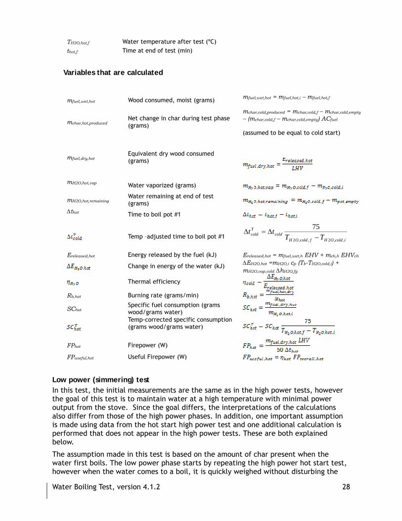
High power test (hot start) In this test, measurements and calculations are identical to the cold start test except that the char remaining is not extracted and weighed. Simply substitute the subscript ‘h’ for the subscript ‘c’ in each variable as in the table below. Char remaining is assumed to be the same as the char remaining from the “cold start” phase.
Variables that are directly measured mfuel,hot,i Weight of fuel before test (grams) mpot,hot,i Mass of Pot with water before test (grams) TH2O,hot,i Water temperature before test (ºC)
thot,i Time at start of test (min) mfuel,hot,f Mass of wood after test (grams) mchar+dish,hot Mass of charcoal and container after test (grams) mpot,hot,f
Mass of Pot with water after test (grams)
Water Boiling Test, version 4.1.2 28
TH2O,hot,f Water temperature after test (ºC) thot,f Time at end of test (min)
Variables that are calculated
mfuel,wet,hot Wood consumed, moist (grams) mfuel,wet,hot = mfuel,hot,i – mfuel,hot,f
mchar,hot,produced Net change in char during test phase (grams)
mchar,cold,produced = mchar,cold,f – mchar,cold,empty
– (mchar,cold,f – mchar,cold,empty) ACfuel (assumed to be equal to cold start)
mfuel,dry,hot Equivalent dry wood consumed (grams)
mH2O,hot,vap
Water vaporized (grams)
mH2O,hot,remaining Water remaining at end of test (grams)
∆thot
Time to boil pot #1
Temp –adjusted time to boil pot #1 icoldOHfcoldOH
coldTcold TT
tt,,2,,2
75−
∆=∆
Ereleased,hot Energy released by the fuel (kJ) Ereleased,hot = mfuel,wet,h EHV + mch,h EHVch
Change in energy of the water (kJ) ∆EH2O,hot =mH2O,i cp (Tb-TH2O,cold,i) + mH2O,vap,cold ∆hH2O,fg
Thermal efficiency
Rb,hot Burning rate (grams/min)
SChot Specific fuel consumption (grams wood/grams water)
Temp-corrected specific consumption (grams wood/grams water)
FPhot Firepower (W)
FPuseful,hot Useful Firepower (W)
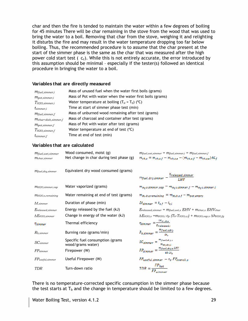
Low power (simmering) test In this test, the initial measurements are the same as in the high power tests, however the goal of this test is to maintain water at a high temperature with minimal power output from the stove. Since the goal differs, the interpretations of the calculations also differ from those of the high power phases. In addition, one important assumption is made using data from the hot start high power test and one additional calculation is performed that does not appear in the high power tests. These are both explained below.
The assumption made in this test is based on the amount of char present when the water first boils. The low power phase starts by repeating the high power hot start test, however when the water comes to a boil, it is quickly weighed without disturbing the
Water Boiling Test, version 4.1.2 29
char and then the fire is tended to maintain the water within a few degrees of boiling for 45 minutes There will be char remaining in the stove from the wood that was used to bring the water to a boil. Removing that char from the stove, weighing it and relighting it disturbs the fire and may result in the water temperature dropping too far below boiling. Thus, the recommended procedure is to assume that the char present at the start of the simmer phase is the same as the char that was measured after the high power cold start test (�cc). While this is not entirely accurate, the error introduced by this assumption should be minimal – especially if the tester(s) followed an identical procedure in bringing the water to a boil.
Variables that are directly measured
mfuel,simmer,i Mass of unused fuel when the water first boils (grams)
mpot,simmer,i Mass of Pot with water when the water first boils (grams)
TH2O,simmer,i Water temperature at boiling (Tsi = Tb) (ºC)
tsimmer,i Time at start of simmer phase test (min)
mfuel,simmer,f Mass of unburned wood remaining after test (grams)
mchar+dish,simmer,f Mass of charcoal and container after test (grams)
mpot,simmer,f Mass of Pot with water after test (grams)
TH2O,simmer,f Water temperature at end of test (ºC)
tsimmer,f Time at end of test (min) Variables that are calculated
mfuel,wet,simmer Wood consumed, moist (g) mfuel,wet,simmer = mfuel,simmer,i = mfuel,simmer,f mchar,simmer Net change in char during test phase (g)
mfuel,dry,simmer Equivalent dry wood consumed (grams)
mH2O,simmer,vap Water vaporized (grams)
mH2O,s,remaining Water remaining at end of test (grams)
∆t,simmer Duration of phase (min)
Ereleased,simmer Energy released by the fuel (kJ) Ereleased,simmer = mfuel,wet,s EHV + mchar,s EHVchar
∆EH2O,simmer Change in energy of the water (kJ) ∆EH2O,s =mH2O,i cp (Tb-TH2O,s,i) + mH2O,vap,s ∆hH2O,fg
Thermal efficiency
Rb,simmer Burning rate (grams/min)
SCsimmer Specific fuel consumption (grams wood/grams water)
FPsimmer Firepower (W)
FPuseful,simmer Useful Firepower (W)
TDR Turn-down ratio
There is no temperature-corrected specific consumption in the simmer phase because the test starts at Tb and the change in temperature should be limited to a few degrees.

Water Boiling Test, version 4.1.2 30
It is important to remember that the goal of this part of the test is to maintain the water at a temperature just under boiling, and one should interpret the results accordingly. Whereas the specific consumption in the high power tests (SCc and SCh) indicated the mass of fuel required to produce one liter (or kilogram) of boiling water, the specific consumption in the simmer phase (SCs) indicates the mass of wood required to maintain each liter (or kilo) of water three degrees below boiling temperature. These are not directly comparable, but rather tell two different measures of stove performance. The same is true for other indicators, like burning rate and firepower.
It is also important to acknowledge that over-reliance on thermal efficiency can lead to misleading results, particularly in the simmer phase. Because thermal efficiency accounts for sensible heat as well as evaporative losses, it rewards for the generation of steam. In most cooking conditions, excess steam production does not decrease cooking time, as the temperature in the pot is fixed at the boiling point. Thus, producing excess steam, while it does reflect wood energy transferred to the cooking pot, is not necessarily a good indicator of stove performance. As we state elsewhere, we wish to de-emphasize the role that thermal efficiency plays in discussions of stove performance and stress other, more informative indicators such as the burning rate and specific consumption at high and low power, and the turn-down ratio, which indicates the degree to which power output from the stove can be controlled by the user.

Water Boiling Test, version 4.1.2 31
Appendix 5. Statistics Lessons for Performance Testing Rob Bailis, formerly UC Berkeley, now Yale University
At least three tests should be performed on each stove. If two models of stove are being compared, the testers should pay attention to the statistical significance of the results of the series of tests. For example, if testers want to compare an indicator of stove performance like specific fuel consumption, it is not possible to say conclusively that one stove is better than another with 100% surety. They can only declare one stove better than another with a certain level of confidence. This level depends on several factors, including the difference in the average specific consumption of each stove, the variability of the test results, and the number of tests that were performed.
While a full discussion of statistical theory is beyond the scope of this stove-testing manual, we will rely on some basic ideas of statistical theory to decide whether or not the results of these tests can be used to make claims about the relative performance of different stove models. For example, Table 1 shows data from a series of cold-start water boiling tests conducted at the Aprovecho Research Center on two different single-pot woodstoves. Each stove was tested three times. From the data, it is clear that the Stove-2 performs much better than Stove-1 in most indicators of stove performance. Notice however, that some indicators of stove performance, namely burning rate and firepower, show difference between stoves. This indicates the importance of considering a multiple indicators when defining stove performance.
Table 1: Results of three high-power cold start Water Boiling Tests on two different stoves
Stove-1 Stove-2 Statistics
units Mean SD CoV Mean SD CoV % difference
between Stove-1 and Stove-2
T-test Significant with 95%
confidence?
Wood consumed g 837 34 4% 468 60 13% -44% 7.55 YES
Time to boil 5 liters of water min 36 3 7% 20 2 10% -44% 6.89 YES
Thermal efficiency -- 0.19 0.01 4% 0.28 0.04 14% 49% -3.30 YES
Rate of wood consumption g/min 23 1 3% 24 4 18% 1% -0.04 NO
Specific fuel consumption g/liter 155 8 5% 91 11 12% -41% 6.77 YES
Firepower kW 6.6 0.2 3% 6.6 1.2 18% 1% -0.04 NO
SD = Standard deviation; CoV = Coefficient of variation ( )mSCo÷=
Table 2, on the other hand, shows the impact of greater variability on the statistical confidence. The table shows the specific consumption derived from two pairs of stove comparisons based on three trials each. In both the higher and lower variability cases, the stoves have the same average specific consumptions, favoring the Stove-2 by 23% (104 compared to 134 g wood per liter of water boiled). However, in the lower variability case the coefficient of variation (CoV) is 6% and 9% for Stove-1 and Stove-2 respectively, while in the higher variability case the CoV is higher (9% and 13% respectively). In the lower variability case, the difference in the two stoves is statistically significant with 95% confidence, while in the higher variability case, it is not. Thus, even though the specific fuel consumption of Stove-2 appears to be better

Water Boiling Test, version 4.1.2 32
than Stove-1 by over 20% we can not say with 95% confidence that Stove-2 is better based on the data with higher variability. In order to rectify the situation, we either need to lower our standards of confidence, or conduct additional tests. If we lower our standards, we can say the observed difference between Stove-1 and Stove-2 is significant with 90% confidence (a 10% chance of error). Alternatively, if we want to maintain the standard of 95% confidence, we can try conducting more tests. For example, if we perform additional tests and the standard deviation in the test results does not change from that shown in the higher variability case of Table 2, then 5 tests of each stove would be sufficient to declare that the observed difference of 23% between Stove-1 and Stove-2 is significant with 95% confidence.
If the CoV of the benchmark values for fuel use and energy use is greater than 25% among 3 tests, the tester should perform an additional test to increase confidence in comparisons. Frequently, these measures have a CoV of 10% or lower. Variability in emissions may be somewhat higher.
Table 2: Hypothetical test results showing effect of data variability on statistical confidence based on three tests of each stove
Stove-1 Stove-2 Statistics
Specific Consumption units Mean SD CoV Mean SD CoV
% difference between
Stove-1 and Stove-2
T-test Significant with 95% confidence?
Lower variability g/liter 134 8 6% 104 9 9% -23% 3.4 YES
Higher variability g/liter 134 12 9% 104 13 13% -23% 2.4 NO

Water Boiling Test, version 4.1.2 33
Appendix 6. Emission Measurement Tami C. Bond and Christoph Roden, University of Illinois Nordica MacCarty, Aprovecho Research
Measuring pollutants from stoves requires more commitment than the simple WBT for efficiency. Here, we discuss some of the considerations for setting up emission measurements. These concerns are often taken into account in designing measurement packages specifically for cookstoves. If you’ve purchased one of those, you can read this section for information. If you’re interested in buying or setting up a measurement system, you should probably make sure you are aware of the issues discussed here.
Which pollutants should be measured? Many pollutants can be measured, but the most important are CO (carbon monoxide) and PM (particulate matter, smoke). CO has some short-term health-effects, and may have some long-term health effects. PM has both short-term and long-term health effects. You should measure both, although CO is relatively easy to measure and PM is more difficult. Your eyes can tell the difference between a stove that is quite smoky and one that is not very smoky. However, it is difficult to visually add all the smoke emitted over the course of a cooked meal. Also, smoke can be harder to see depending on its color, on lighting, and on contrast with background.
Other emissions are also of interest. For example, polyaromatic hydrocarbons (PAH) can have some specific health effects. Some reactive gases, known as volatile organic compounds (VOCs) could contribute to ozone formation. Non-CO2 greenhouse gases (GHGs, like methane) may be of interest if your stove project could be funded for climate reasons. PM affects climate as well, especially the dark part (known as black carbon). Most of these pollutants are more challenging to measure, and are best done by a regional testing center.
Capturing the exhaust Emissions from solid-fuel burning are variable in both time and space. Measuring in only one place in the exhaust or over a short period of time, does not give accurate emission readings. Some method is needed to average over all events during combustion. Because the burning is so unsteady, you cannot take a one-time measurement with a gas probe as furnace technicians do. For example, a very large fraction of the pollutants are emitted during ignition or addition of wood. A one-time sample taken during this time would overestimate average emissions; a single sample that missed that time would understate the emission rate.
Pollutants change as they leave the hot combustion chamber. These changes might not affect CO concentrations, but they are quite important for PM. One of these changes is caused by “semi-volatile organic compounds,” which act similarly to water. They are gaseous in the hot exhaust and then condense into particles as the exhaust cools down. Measuring realistic emissions requires waiting until the exhaust is cooled. If you measure hot exhaust, you can greatly underestimate the particle concentrations.
Stove exhaust is also wet. It contains water from the fuel, from combustion, and from the cooking pot. As you cool the exhaust, water condenses, and that liquid water can damage the pollutant measurements. The exhaust must be dried before you draw it through the measurements. In addition, water can be incorporated into particles if the

Water Boiling Test, version 4.1.2 34
relative humidity (moisture) in the exhaust is high. This gives the particles more apparent mass than they would have when dry, so that the particle concentration could be measured too high.
So, the sampling procedure must: (1) integrate the sample over the entire burn cycle; (2) integrate the sample over the entire exhaust plume; (3) cool and dry the exhaust; and (4) relate emissions to fuel burned. The first and last of these are usually done by choosing appropriate data collection and analysis, and will be discussed later.
Cooling and drying can be accomplished by one of two methods. Dilution with clean, dry air is the method we recommend. This cools the exhaust to near room temperature, and reduces the water vapor in the hot exhaust to concentrations where it will not condense. Another method, used in classic U.S. EPA stack sampling, consists of sampling with a train of processes: collecting PM from the hot exhaust, drying, cooling, and collecting additional condensed material in cold impingers. We consider the latter method too complex for most stove designers, and much modern sampling is conducted with dilution, anyway (Hildemann et al., 1989; U.S. EPA, 2000).
Some collection methods are shown in Table 1 on the next page. We recommend the hood method because cooling and drying are done simultaneously through natural dilution, and because the equations are easiest to implement. The laboratory air must be clean and dry if it is used as dilution. This means that the hood must capture all of the stove exhaust, or pollutants will accumulate in the room. Additional dilution with dry compressed air (not shown) may be needed if the surrounding air is very humid.
Data collection We stated earlier that the sampling procedure must integrate the sample over the entire burn cycle. For this, you need either measurements that record real-time data (that is, second by second), or an integrated sample (bag or filter) that collects samples from all times during the burning. In other words, you need to either collect data which you can average later, or you need to produce a physical average by collecting a small, continuous sample throughout the test. We highly recommend real-time data collection. Many of the pollutant measurements are real-time, anyway, and the data are extremely instructive for the varying combustion that occurs in wood stoves.
When we discuss specific pollutant measurements, we will indicate which methods provide real-time data and which are integrated by taking a physical sample over a long time period.
Relating pollutant concentrations to fuel burned All instruments measure pollutant concentrations. While concentrations are directly relevant to human health, additional measurements or analysis are needed to relate the measured pollutants to the amount of fuel burned and the task performed. Pollutant per fuel burned is often given the name “emission factor.”
The room method requires some way to measure the room’s air exchange rate. Air exchange rate is affected by variation in room temperature, outdoor temperature, and wind pressure. The calculation of air exchange rate can be rather uncertain, which is why we don’t recommend the room method to evaluate emissions. If you are using a real-time CO device, the exchange rate can be inferred from the decay of the CO concentration after the test is complete.

Water Boiling Test, version 4.1.2 35
Table 1. Methods of collecting stove exhaust.
Description Advantages/Disadvantages Sketch
Direct stack sampling: Draw sample directly from chimney.
Advantages: Setup is extremely simple.
Disadvantages: No cooling or drying of air unless sampling “train” is used; doesn’t work for stoves without chimneys.
sampler
Room method: Measure room concentration indoors and the air exchange rate in a room, then calculate the emission rate.
Advantages: The measurement and setup are fairly simple, as long as a suitable room is available.
Disadvantages: Requires extra equations to infer emission rate; not as easy to see immediate changes in the burning; assumes that air in room is mixed well.
sampler
Hood method: Capture all the exhaust in a hood, and measure the flow rate through the hood.
Advantages: Shows instant changes in burning; flow rate is easy to measure. Disadvantages: Requires building an exhaust hood and adding a small fan; less portable.
sampler
Both direct stack sampling and the hood method can use two methods to relate concentrations to fuel burned: exhaust flow and carbon balance. Both have been used for stove testing: Ballard-Tremeer and Jawurek (1996) relied on exhaust flow, and the carbon balance method has been used by Zhang et al. (2000) and Roden et al. (2006). The best approach is using both and making sure the results match. Using only one is sufficient for field measurements.
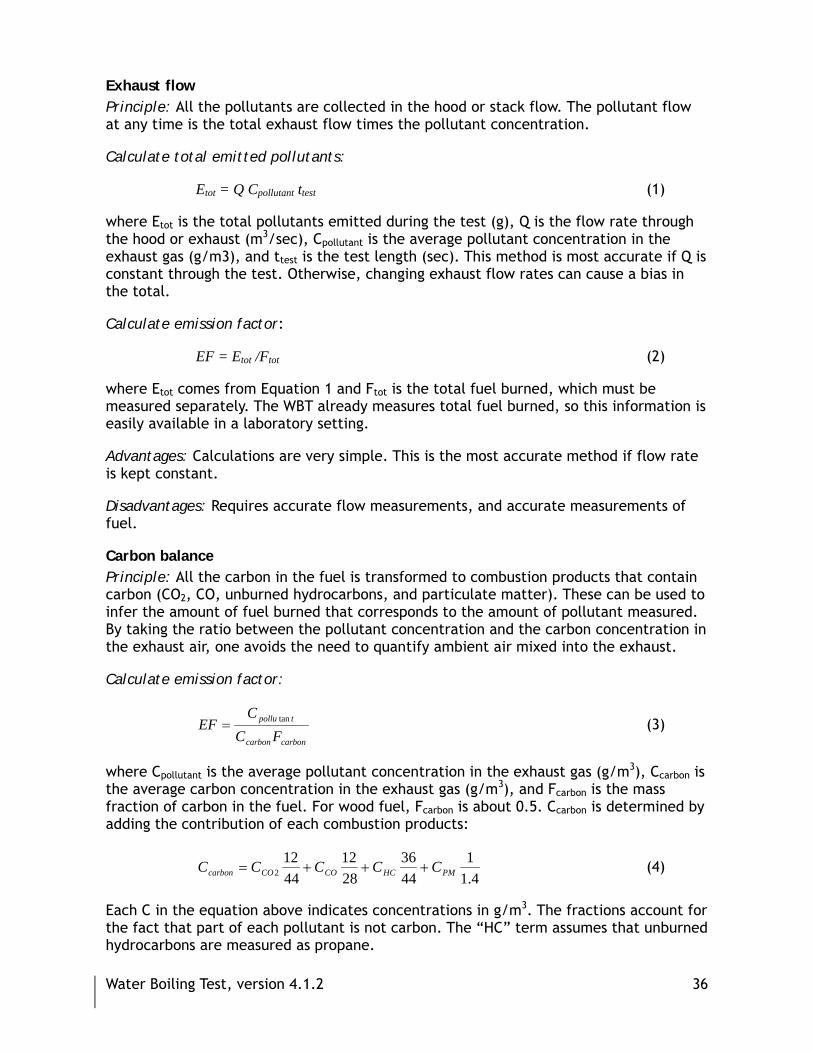
Water Boiling Test, version 4.1.2 36
Exhaust flow Principle: All the pollutants are collected in the hood or stack flow. The pollutant flow at any time is the total exhaust flow times the pollutant concentration.
Calculate total emitted pollutants:
Etot = Q Cpollutant ttest (1)
where Etot is the total pollutants emitted during the test (g), Q is the flow rate through the hood or exhaust (m3/sec), Cpollutant is the average pollutant concentration in the exhaust gas (g/m3), and ttest is the test length (sec). This method is most accurate if Q is constant through the test. Otherwise, changing exhaust flow rates can cause a bias in the total.
Calculate emission factor:
EF = Etot /Ftot (2)
where Etot comes from Equation 1 and Ftot is the total fuel burned, which must be measured separately. The WBT already measures total fuel burned, so this information is easily available in a laboratory setting.
Advantages: Calculations are very simple. This is the most accurate method if flow rate is kept constant.
Disadvantages: Requires accurate flow measurements, and accurate measurements of fuel.
Carbon balance Principle: All the carbon in the fuel is transformed to combustion products that contain carbon (CO2, CO, unburned hydrocarbons, and particulate matter). These can be used to infer the amount of fuel burned that corresponds to the amount of pollutant measured. By taking the ratio between the pollutant concentration and the carbon concentration in the exhaust air, one avoids the need to quantify ambient air mixed into the exhaust.
Calculate emission factor:
carboncarbon
tpollu
FCC
EF tan= (3)
where Cpollutant is the average pollutant concentration in the exhaust gas (g/m3), Ccarbon is the average carbon concentration in the exhaust gas (g/m3), and Fcarbon is the mass fraction of carbon in the fuel. For wood fuel, Fcarbon is about 0.5. Ccarbon is determined by adding the contribution of each combustion products:
4.1
14436
2812
4412
2 PMHCCOCOcarbon CCCCC +++= (4)
Each C in the equation above indicates concentrations in g/m3. The fractions account for the fact that part of each pollutant is not carbon. The “HC” term assumes that unburned hydrocarbons are measured as propane.

Water Boiling Test, version 4.1.2 37
Advantages: No measurements of flow or fuel are needed. This is an advantage in field settings where such observations can be difficult; if you capture a representative sample of exhaust, a hood or exhaust stack is not even needed. Just as accurate as the exhaust-flow method if a hood is used and flow is constant.
Disadvantages: Requires an extra measurement of carbon dioxide. Less accurate than hood method if the sampled flow is not constant. Carbon content of fuel is often uncertain to 10%, which translates to an uncertainty in emission factor. Some measurement programs do not measure unburned hydrocarbons; however, these are small fractions of the total carbon.
Pollutant measurements Here, we discuss measurements to quantify each combustion product. In this section, we will not list products made by specific companies, because such a list would be quickly outdated. Instead, we will discuss the physical principles of pollutant measurements. After you have considered the advantages and disadvantages of each type of measurement, choose one, and then seek an analyzer based on that physical principle. We do indicate approximate costs in $US (as of 2009), which are part of the advantages or disadvantages.
In addition to pollutant measurements, the temperature, pressure, and relative humidity at the concentration measurement point should always be recorded before and after each test. If possible, these values should be monitored continuously throughout the test.
Carbon monoxide Needed: Always
Method 1: Electrochemical (real-time) Principle: CO causes a reaction within a chemical cell, which causes current to flow.
Advantages: Cheap ($US 200-400)
Disadvantages: Relatively slow response time (~30 sec), temperature sensitivity, and cross-sensitivity to other gases; cells can be chosen to compensate for this sensitivity. Needs frequent calibration.
Recommendation: Good enough for in-field stove testing with frequent calibration.
Method 2: Non-dispersive infrared (real-time) Principle: CO absorbs light at a specific wavelength.
Advantages: Rapid response (limited only by flow rate and cell volume); accurate.
Disadvantages: Expensive ($US 5,000-10,000). [Note: These are getting cheaper—need more research.]
Recommendation: Should be used in testing labs that require high accuracy.
Water Boiling Test, version 4.1.2 38
Particulate matter Needed: Always
Method 1: Gravimetric (integrated) Principle: Draw the air sample through a filter (a membrane disk) that catches the particles. The filter must be weighed before and after measurement; hence the name “gravimetric.” The difference between the two weights is the total mass of collected particles.
Advantages: Considered a standard method; most accurate for absolute mass. Particulate matter can be analyzed with other techniques to obtain chemical composition.
Disadvantages: Not real-time (no immediate information or information on events). Expensive if you do not already have a balance; see discussion below. It is easy to contaminate filters in field settings.
Recommendation: Should be used in testing labs that require high accuracy, along with optical measurements that provide real-time information.
Required components: For each test: filters (~$US 1-2 each) and petri dishes for storing filters ($1 each). Single purchases: filter holders ($50-500 each); pump ($200-400 USD); measurement of flow rate through the filter (~$100); balance ($5,000-25,000 depending on needed accuracy, which depends on sample size); size-selective inlet (cyclone or impactor) to exclude larger particles (~$1,000); glove box or environmental chamber to control humidity and temperature of weighing environment.
Equation to obtain concentration:
testfilter
beforefilterafterfilterPM tQ
MMC ,, −
= (5)
where M is the mass of the filter (g), Qfilter is the flow rate through the filter; and ttest is the test length (sec).
Brief instructions: Humidity and temperature of the air affect the filter weight; that’s why the glove box or environmental chamber is needed. Be sure to equilibrate the filter (24 hours) to the box relative humidity prior to both weights. Keep new and sampled filters in individually sealed containers, handle the filter with forceps, wear gloves, and store the filter and container in a freezer once a sample has been collected. You should investigate standard operating procedures for filter weighing before starting such measurements.
Method 2: Optical (real-time) Principle: The mass of PM is inferred from how the particles interact with light. A beam of light is passed through exhaust air, and the reduction in transmitted light or increase in scattered light is measured.
Advantages: Rapid response; no post-analysis required.
Disadvantages: Cheaper than entire gravimetric setup ($1000-5000), but still costly. Light interaction depends on the particles’ size and composition, and for that reason,

Water Boiling Test, version 4.1.2 39
the relationship between optical methods and mass can be a large source of uncertainty. The name “optical” methods applies to three different methods of using light to measure particles; see Table 2 for comments.
Recommendation: We recommend scattering measurements for most in-field applications, because these are least sensitive to particle composition. However, the uncertainties in inferring mass should not be ignored, especially when comparing stoves.
Other methods Research laboratories sometimes use other methods of measuring mass in real time. Here, we have not discussed the Tapered Element Oscillating Microbalance (TEOM) because it has difficulty measuring semi-volatile material. We have also not discussed real-time, size-resolved measurements such as the Scanning Mobility Particle Sizer (SMPS) or Electrical Low Pressure Impactor (ELPI), because we consider these too difficult to operate and maintain at the average stove lab.
Carbon dioxide Needed: When using carbon balance method
Method 1: Non-dispersive infrared (NDIR, real-time) Principle: CO2 absorbs light at a specific wavelength.
Advantages: This is the only reliable method for measuring carbon dioxide. Fortunately, these devices have become much cheaper ($US 150-600).
Recommendation: You must use infrared measurements for CO2.
Table 2. Three types of optical measurements
Measurement Advantage Disadvantage
Opacity (extinction, or scattering plus absorption)
Easiest and often cheapest Absorbing (black) particles have much higher extinction than non-absorbing particles, so opacity-to-mass ratio varies widely
Scattering Least sensitive to particle composition
Sensitive to particle size; can be most expensive
Absorption (filter transmittance or black smoke)
Most common measurement Particles that do not absorb light will not be measured
Water Boiling Test, version 4.1.2 40
Method 2: Inference based on oxygen content Principle: Ambient air should have 20.9% oxygen content. Missing oxygen must have been turned into CO2 or another combustion product.
Advantages: O2 measurement is very simple.
Disadvantages: Requires knowledge of the carbon, hydrogen and oxygen composition of burning fuel. If the air has been diluted, CO2 at the measurement point is low, and O2 is high. In this situation, inferring a CO2 measurement requires taking the small difference of two large numbers (ambient O2 minus exhaust O2), which is quite uncertain.
Recommendation: Do not use an O2 balance to infer CO2. Check whether CO2 reading is “calculated” or “inferred;” if so, it is taken from an O2 reading, with the associated uncertainties. However, an O2 meter at the outlet of a combustion chamber can help you assess excess air and hence combustion quality.
Exhaust flow rate Needed: When using exhaust flow to relate pollutant measurements to fuel use
An orifice, or a plate with a hole which causes a pressure drop, is a common way of measuring exhaust flow. For turbulent flow, the flow rate is proportional to the square root of the pressure drop. The pressure gauge needed is about $US 60 US, and the orifice can be made very cheaply. The flow versus pressure relationship should be calibrated by comparing with a more accurate flow device. Before installing an orifice, you should consult an engineering text book to determine where to locate the pressure taps, and where to place the orifice.
Pitot tubes can also measure exhaust flow using the pressure difference between a tap facing into the flow and a tap shielded from the flow. Another option that is designed for use in sheet metal ducts is called a “flow grid” ($US 40). It uses the pitot-tube principle at four points in the flow.
Oxygen content Needed: To assess the amount of excess air in the stove’s combustion chamber, providing design input
Oxygen analyzers are frequently included in packaged combustion analyzers. An oxygen measurement made after the needed dilution is not useful for stove design. Instead, this measurement should occur directly downstream of the combustion chamber, or sometimes inside it. A program that assesses only the performance of stoves need not include an oxygen measurement. However, an oxygen measurement can provide critical input for a stove designer.
A caution about packaged analyzers Many packaged combustion analyzers are designed for assessing furnaces (natural-gas or oil) or automobiles. While these analyzers may appear convenient, some issues should be considered before purchasing them. (1) The combustion devices for which the packaged analyzers are designed have steadier combustion than cookstoves, so this emission testing equipment is often designed to take just a single sample, not a real-time sample. (2) Packaged analyzers are made to sample the concentrated exhaust in a stack, not diluted gas above a stove, so that their measurement ranges are usually
Water Boiling Test, version 4.1.2 41
higher than the ideal stove measurements. (3) These analyzers usually have no ability, or very crude ability, to sample particulate matter. Even “black smoke” measurements are taken over a small period of time and use the least desirable detection (see Table 2). (4) Finally, these analyzers frequently use the O2-balance method to detect CO2.
Packaged analyzers, especially those used for furnaces, may be appropriate for measuring combustion conditions within the stove. However, they should be used with caution unless they are designed for cookstove emission measurements.
Data acquisition If pollutants are monitored in real-time, the real-time data will need to be recorded and averaged after the test. There are rugged, inexpensive dataloggers that collect real-time data and later can download it to a personal computer (or a Palm Pilot). To see your data while the measurement is being taken, a computerized data acquisition system is needed. This system will include a card that talks to the computer (“A/D” or analog-to-digital board), another board where the signals are collected, and software. The cost, not including the computer, ranges from $US 250-1000.
Users need to be somewhat computer-literate to retrieve the data from the loggers and produce meaningful results. Dataloggers should include a training manual and a spreadsheet that does most of the work.
Summary Figure 2 (next page) shows the equipment we recommend to perform the simplest emission measurements. The equipment is also listed in Table 3, at the end of this Appendix. We recommend measuring both flow and carbon dioxide; the expense is not high and the additional information gives confidence. You can alter this measurement plan, keeping in mind the principles described above.
Citations Ballard-Tremeer, G., and H.H. Jawurek (1996), Comparison of five rural, wood-burning cooking devices: efficiencies and emissions, Biomass & Bioenergy, 11 (5), 419-430.
Brockmann, J.E., Sampling and Transport of Aerosols, in Aerosol Measurement: Principles, Techniques and Applications, edited by K. Willeke, and P.A. Baron, pp. 77-111, Van Nostrand Reinhold, New York, 1993.
Roden, C.A., T.C. Bond, S. Conway, and A.B.O. Pinel (2006), Emission factors and real-time optical properties of particles emitted from traditional wood burning cookstoves, Environ. Sci. Tech., 40, 6750-6757.
Zhang, J., K.R. Smith, Y. Ma, S. Ye, F. Jiang, W. Qi, P. Liu, M.A.K. Khalil, R.A. Rasmussen, and S.A. Thorneloe (2000), Greenhouse gases and other airborne pollutants from household stoves in China: A database for emission factors, Atmos. Env., 34, 4537-4549.

Water Boiling Test, version 4.1.2 42
Figure 2. Setup for testing emissions. Thick solid lines show smoke collection; arrows indicate direction of airflow; dashed lines are electrical connections. See next page for further instructions and Table 3 for equipment discussion.
Real-timePM sensorCO2 FilterCO
PumpData
Acquisition
Smoke Sample
Air Flow andTemperature Sensor
Blower
Hood
Most ofexhaust
Fire or stove
MixingBaffles
Cyclone
Notes:
- Hood should be at least 1 m above the stove top to avoid affecting the combustion. If you fear that some smoke may escape, you may enclose the fire or stove with light sheets of hanging cloth— do not extend the hood downward or you may affect the flow through the flame. BE SAFE— keep all enclosures well away from flames!!
- Sampling should be at least 8 duct-diameters downstream of the mixing baffles, and at least 2 duct-diameters upstream of the blower. For example, if the duct is 15 cm (6 inches) in diameter, the sample should be at least 90 cm from the baffles and at least 30 cm from the blower.
- Sample probe must be facing into the flow. Good practice says that sampling should be isokinetic—that is, the flow into the sample probe must be traveling at the same speed and direction as the flow in the collection duct. If you are absolutely sure that your stove exhaust does not contain particles lofted by a fan (i.e. your stove has natural draft), then the diameters of the particles will be quite small. In this case, the sampling velocity may vary by a factor of 3 from isokinetic, either up or down. For particles with diameters less than 500 nanometers, this introduces no more than a 2% error [Brockmann et al., 1993, and equations therein].
- Prior to sample collection, all tubing must be made of stainless steel or conductive tubing to avoid particle loss and reaction with material deposited in the sampling system. Keep tubing as short as possible. Stainless steel is preferred over silicone tubing because of sampling issues with the latter.

Water Boiling Test, version 4.1.2 43
Table 3. Equipment for simple emission measurement
Equipment (Range, if applicable)
Analysis Method/Purpose Cautions
Exhaust hood, including blower and collection duct (80-150 m3/h)
Collect exhaust Must not affect flow through stove
Flow grid Measurement of flow through exhaust
Must be calibrated before use
Pressure transducers (2) (0-25 cm H2O or 2500 Pa)
Measure pressure drop across flow grid, and pressure at concentration measurement
Scattering measurement (0-5000 µg/m3)
PM concentration Scattering-to-mass ratio is uncertain. Repeatable to 10 µg/m3 for particles of same composition.
Carbon monoxide (0-2000 ppm)
Electrochemical for simple measurements; non-dispersive infrared for very accurate lab
Calibrate frequently (need calibration gas). Should be repeatable to 10 ppm.
Carbon dioxide (0-5000 ppm)
Non-dispersive infrared Don’t use O2 balance. Need calibration gas. Should be repeatable to 10 ppm.
Measurement temperature (0-100 C)
Thermocouple Should remain near room temperature
Measurement relative humidity
Capacitive sensor Should remain below 50% RH
Real-time data acquisition Filter-based particulate matter setup
For accurate lab only; see discussion above for components
Cyclone Remove particles greater than 2.5 µm diameter from sample stream
Flow rate through cyclone affects size of particles removed. Non-stove applications may have significant PM>2.5 µm and this “cut size” should be revisited in another situation.
Pump Draw air through sampling system

Water Boiling Test, version 4.1.2 44
Appendix 7. Data entry sheets You may print these sheets to fill out by hand. To perform the calculations that result in WBT metrics, you should enter all the data in the Excel file “WBT_data-calculation_sheet_###.xls” (### is the version number, such as 4.1).

Water Boiling Test - General Information Version 4.1Test & stove description Fuel description
Name of Tester(s) Your general description
Test Number or Code Fuel type 1
Date Fuel description 1
Test Location Average length (cm)Cross-sectional dimensions (cm x cm)
Stove Type/Model Default values (looked up)Manufactured by Gross calorific value - HHV, kJ/kg
Description and Notes Net calorific value - LHV,kJ/kg
Char calorific value - LHV,kJ/kg
If possible, enter a calorific value from measurements of local fuel below.Check box if you have a measured calorific value
Ambient conditions Check box if measured calorific value is for dry fuelAir temperature (C) Air relative humidity (%) Measured gross calorific value HHV measured, kJ/kg
Local boiling point (C) Measured net calorific value LHV, kJ/kg
Notes or description about stove or operation not included elsewhere on this form Assumed net calorific value LHV, kJ/kg
Values to be used for testsGross calorific value - HHV, kJ/kgNet calorific value - LHV, kJ/kg
Description of firestarter (e.g. paper, fluid) and small wood or kindling(note: Kindling should be weighed and reported with wood)
When do you add new fuel to the fire?
How is fire started?
Do you control the air above or below the fire? If so, what do you do?
Do you control the air above or below the fire? If so, what do you do?
Description of operation during the simmering testDescription of operation during the high-power test
How is fire started?
How often do you feed the fire without adding fuel (e.g. push sticks)?
How much fuel do you add at one time?
How often do you feed the fire without adding fuel (e.g. push sticks)?
When do you add new fuel to the fire?
How much fuel do you add at one time?
(Select from list)
(Select from list)

Water Boiling Test, version 4.1.2 46
Fuel moisture content worksheet
Test-1 Test-2
1 2 3 1 2 3
Piece 1 Piece 1
Piece 2 Piece 2
Piece 3 Piece 3
Average moisture content (%) Average moisture content (%)
dry-basis wet-basis dry-basis wet-basis
Test-3
1 2 3
Piece 1
Piece 2
Piece 3
Average moisture content (%)
dry-basis wet-basis
Fuel moisture content worksheet
(% dry basis) (% dry basis)
Instrument reading (% dry basis)
If you are determining fuel moisture with the Delmhorst J-2000 or similar handheld moisture meter, take 3 pieces of fuel at random from the stock used for each test and measure each in three places along its length. Enter the results in the gray spaces below. The worksheet will automatically calculate average moisture content on a dry and wet basis.
If you are using another means to determine fuel moisture, enter the moisture content in the blue spaces next to the appropriate label (dry-basis or wet-basis).
Instrument reading Instrument reading
The Delmhorst J-2000 moisture analyzer measures fuel moisture on a dry basis. To find moisture on a wet basis, use the following equation:
This spreadsheet does this calculation automatically if a value is entered in the dry-basis space. Output requires moisture content on a wet basis, so the conversion is very important.
dry
drywet MC
MCMC
+=
1

Water Boiling Test, version 4.1.2 47
Water Boiling Test - Test Entry FormThese values are not linked to the Test sheets. This sheet is provided so you can print an easy data entry form. You will have to enter these values in each Test sheet to obtain the calculations.
Air Temperature Name of Testers
Wind Conditions Date
Stove Type/Model
Fuel Dimensions Test Number
Moisture Content (wet basis) Location
Fuel Type
Dry Weight Pot 1 Notes
Dry Weight Pot 2
Dry Weight Pot 3
Dry Weight Pot 4
Weight Container for Char
Local Boiling Point ** enter on General Information
Start End Start End Start End
Time
Weight of Wood
Water Temperature, Pot 1
Water Temperature, Pot 2
Water Temperature, Pot 3
Water Temperature, Pot 4
Weight of Pot 1 with water
Weight of Pot 2 with water
Weight of Pot 3 with water
Weight of Pot 4 with water
Fire Starting Materials
Weight of Charcoal + Container
Cold Start Hot Start Simmer

Water Boiling Test, version 4.1.2 48
Appendix 8. Outstanding issues in the WBT The Water Boiling Test, and other standardized tests, are constantly being examined and improved. Below we discuss some questions of current interest in the Water Boiling Test, which may be updated in future versions. These issues may be of little interest to most testers. They are included here for a more technical audience. We suggest laboratory testing that could resolve some of these issues or provide data to support discussions.
Wood type and moisture content The choice of wood for the WBT is a subject of active discussion. Some laboratories recommend manufactured, dry, square wood with relatively small cross-sections. Wood with these characteristics provides greater repeatability among tests. However, it is not similar to most wood used in the field.
Parametric testing should be conducted to compare measured performance for the same stove using manufactured or square wood and using representative wood.
Pot insulation (Morgan DeFoort, Colorado State University)
The use of insulation above the water is another change proposed to reduce variability. This insulation consists of any closed-cell foam capable of handling temperatures seen during testing. Ideally the foam is cut so that it fits inside the pot and sits on top of the water inside. This insulation reduces the water lost from the pot; it also reduces the pot’s heat requirement, which could lead to unrepresentative operation. Adding such insulation decreases the amount of energy required, and will probably decrease the specific fuel consumption and emissions. Thus, results from a WBT with an insulated pot should not be compared with this version of the WBT.
Parametric testing should be conducted to determine whether a stove optimized with pot insulation results in an optimal stove for conditions without pot insulation.
Test sequence (Crispin Pemberton-Pigott, New Dawn Engineering)
The current test sequence of cold-start high-power, hot-start high-power, and finally simmering stores the maximum possible heat in the stove prior to the simmering test. This storage could give an unfair advantage to high-mass stoves, which can simmer water more easily using the stored heat. One suggestion is to alter the test sequence so that the simmer test occurs in the middle, so that simmering occurs with only the heat stored in the first cooking cycle. The practical disadvantage is that tests completed with the original test sequence will not be comparable. High-mass stoves may have an advantage during the simmering phase, but high-mass stoves have a disadvantage that is shown by comparing results of the cold- and hot-start phases.
Some exploratory tests using a cold-start, simmer, hot-start, simmer cycle could be accomplished to examine the differences in simmering results after each high-power test. In addition, a greater understanding of in-use fuel cycles should be brought to this question. How frequently are completely cold, high-mass stoves found in practice?

Water Boiling Test, version 4.1.2 49
Thermal efficiency (Initial ideas from Crispin Pemberton-Pigott, New Dawn Engineering; description by Laura Fierce, University of Illinois)
Efficiency is one of the most common metrics taken from the Water Boiling Test. The test is supposed to help stove designers understand how well energy is transferred from the fuel to the cooking pot. However, the measurement of energy transfer is incomplete, leading to a misrepresentation of thermal efficiency.
A simple energy balance for the fire, stove and cooking pot is shown in the figure below. Blue indicates quantities currently used in the WBT to calculate energy transferred to the pot, red indicates quantities used to calculate energy generated by the fuel, and black indicates quantities that are not currently used in the calculations. The energy transferred to the water is actually the sum of the latent heat, sensible heat, and the heat transferred away from the pot via convection, conduction, and radiation. This latter heat is not accounted for in the WBT calculation, but it is very important: at simmering, the stove’s mission is to counterbalance this heat loss, not to evaporate water from the pot. Yet, the evaporation of water, rather than the heat loss from the pot, is measured. This mismatch between the measured quantity and the desired service also occurs during the high-power, water-heating tests, but the impact is not as great.
Heat generated by fire
Heat transferred to pot
Heat transferred to stove
Heat “leaking”
Energy to heat water = cp*m*(Tf-Ti) Heat transferred from boiling
water via convection, conduction and/or radiation
Energy to boil water = m*hfg
Boiling H20
There has been a proposal to use the difference between high-power and low-power tests to provide a better measure of thermal efficiency. This proposal has not been thoroughly evaluated with laboratory experiments.
Improved calculations of thermal efficiency should be pursued and verified, particularly if they can be accomplished without a change in protocol. Thermal efficiency measures should be viewed with caution, particularly from the simmering test. A better measure is the quantity of fuel required to complete a task, known as specific consumption.

Water Boiling Test, version 4.1.2 50
Humidity in ambient air (Robert van der Plas)
The emission testing setup given in this document assumes that laboratory air is clean and dry. However, many locations have very humid air. High relative humidity in ambient air contributes to two problems in emission testing. First, the laboratory air is too moist to dry the sample, which contains water from both the combustion and the cooking pot. Condensation may occur within the sampling system. Second, smoke particles increase in size when relative humidity is high, causing them to scatter more light. This increased scattering would be interpreted as a greater mass.
A subsequent investigation should identify the amount of dilution air required at specific humidities to avoid these problems, and include these recommendations in the document. A description of a dilution dryer should be included for environments that are too humid.
Power to Boil (H. S. Mukunda, CGPL, Indian Institute of Science, Bangalore)
A stove might operate inefficiently if too much power is provided for the needed task. Test results are highly dependent on the power level chosen. Some guidance should be provided for acceptable ranges of firepower needed to boil the standard 2.5L and 5L of water. We should collect data on observed firepower from regional testing laboratories to provide a range for users.