The Vital Link - West Alarm Security Systems stations, the PCS250 is the vital link that keeps you...
56
PCS250 GPRS/GSM Communicator Module V2.12 The Vital Link Reference and Installation Manual PCS250-EI03 Printed in Canada - 11/2014
Transcript of The Vital Link - West Alarm Security Systems stations, the PCS250 is the vital link that keeps you...

PCS250 GPRS/GSM Communicator Module V2.12
The Vital Link
Reference and Installation Manual
PCS250-EI03Printed in Canada - 11/2014


Table of ContentsIntroduction......................................................................... 4
Features .................................................................................................. 4
Overview ............................................................................... 6System Components ......................................................................... 6LED Feedback ....................................................................................... 7SIM Card Functionality ...................................................................... 8Tamper Switch Functionality ......................................................... 8Specifications ....................................................................................... 9
Connections ......................................................................10SIM Card Connection .......................................................................10GSM vs. GPRS Connections ...........................................................12Communication Bridge ..................................................................13UC300 Connection ...........................................................................14Optional Power Supply Connections ........................................15Using an External Power Input ....................................................15VDMP3 Connection (Optional - GSM mode only) .................15Using an RS485 Link (GSM mode only) .....................................16
Installation .........................................................................18Antenna Extension Installation (Optional) ..............................18Module Installation ..........................................................................18
Configuring the PCS250 ................................................19Frequency Band ................................................................................19Bandwidth Saver Mode ..................................................................19SMS Forwarding ................................................................................19Configuring GSM Network Provider Information .................20Configuring Babyware Access .....................................................22Programming GSM Reporting Options ....................................22Programming and Registering GPRS Reporting Options ..23SMS Backup Reporting ...................................................................25Configuring the PCS250 for SMS Backup Reporting ............25Troubles ...............................................................................................27Text message notification .............................................................28SMS Language ...................................................................................28Arm/Disarm System via Text Message ......................................29List of SMS Commands ...................................................................29
Upload/Download ..........................................................32Public Network (GPRS mode only) .............................................32Private Network .................................................................................33
Module Supervision ........................................................34End User SMS Programming ........................................................35View GSM IP Information ...............................................................36
Text Messages ...................................................................38

Page 4 Introduction
Chapter 1: IntroductionThe PCS250 GPRS/GSM Communicator Module is the next evolutionary step in wireless communication solutions for Paradox control panels. Providing reliable and fast communication between properties and their respective monitoring stations, the PCS250 is the vital link that keeps you connected.
Using cellular networks, the PCS250 reports to the monitoring station’s automation software via two channels (GPRS/GSM), ensuring that all communication is fast, reliable, and stable. The PCS250 can be used as a backup to a traditional landline, or as a primary communicator where no landline is available. It also adds remote home control capabilities to a system, allowing you to arm/disarm with a simple text message (SMS). Feel safe by taking control of your system, wherever you are.
Re-imagined through an array of new technologies, contemporary design, and a modern hi-tech finish, the PCS250 GPRS/GSM Communicator Module enables Paradox systems to be remotely controlled, continuously monitored, and reliably connected at all times.
Features• Compact, sleek design• Instant notification of panel supervision loss• Easily arm/disarm the system via SMS (feature not available
when using the UC300 Universal Converter)• Report alarms by sending pre-recorded voice messages to
up to eight telephone numbers using the optional Paradox Plug-in Voice Module (VDMP3)
• Report alarms by text messages to up to 16 cellular phone numbers
• Simple installation with 4-wire serial connection• Supports 2 GSM provider SIM cards for provider redundancy• Tamper switch support• Optional rod antenna can be installed up to 18m (60ft) from
the module using optional antenna cable extensions depending on the local signal strength
• Increase the distance between the panel and the PCS250 with an RS485 link (GSM mode only (E-bus)). A CVT485 module must be added at the panel.
• In GPRS mode, messages are secured with 128-bit (MD5) and 256-bit (AES) encryption

Introduction Page 5
Included Items• PCS250 Communicator Module• Serial cable• GPRS Module
Required/Optional Items• Active SIM card (required)• Second SIM card (required for provider redundancy)• Paradox Plug-In Voice Module VDMP3 (optional)• Antenna extension (optional)• 12 Vdc external power supply (optional)
Compatibility• EVO192 panels V2.02 or higher • EVOHD panel V1.0 or higher• UC300 V1.01 or higher• K641 and K641R keypads V1.51 or higher • K641+ V1.0 or higher• SP series V3.42 with K32LCD keypads V1.22• E55 panels V3.0 (labels to be programmed via BabyWareE65
panels V2.1 (labels to be programmed via BabyWare)• MG series V4.0 or higher with K32LCD keypads V1.22 or higher
For latest updates visit paradox.com or contact your local distributor.

Page 6 Overview
Chapter 2: OverviewThis section provides an overview of the Paradox PCS250 GPRS/GSM Communicator Module. It covers technical specifications, light-emitting diode (LED) functionality, and an overview of the PCS250 system components.
System Components1) GPRS Module with dual SIM card slots 2) Audio jack3) InField upgrade connector4) Future use5) RS485/power terminal 6) Future use7) Serial cable connector 8) Tamper screw9) Tamper switch10) Audio module connector (e.g., VDMP3)11) System LEDs (refer to “LED Feedback” on page 7)
1
2
3
4
7 6 5
10
11
9
8

Overview Page 7
LED FeedbackThe following table provides a description of the PCS250 Communicator Module LEDs.
Communication LossUpon loss of communication with the panel, the PCS250 LEDs will behave in the following manner:1) GPRS or GSM LED displays are off; the SIM card and signal
strength LEDs display their status for about 3 seconds. 2) Signal strength LED remains OFF; GSM (green) is turned ON,
followed in turn by GPRS (green), SIM2 (orange) and SIM1 (red). When a LED is ON, all others are off. Each LED lights for about 200 ms. This sequence is repeated two times.
3) This cycle repeats until communication is restored.
LED Feedback
SIM Card 1
Solid green = SIM card 1 is installed on the GPRS Module Quick green flashing = SIM card 1 is exchanging dataSlow green flashing = Searching the networkFlash red (once) = SIM card 1 is defectiveOff = SIM card 1 is not installed, not active, or currently not in use
SIM Card 2
Solid green = SIM card 2 is installed on the GPRS ModuleQuick green flashing = SIM card 2 is exchanging dataSlow green flashing = Searching the networkFlash red (once) = SIM card 2 is defectiveOff = SIM card 2 is not installed, not active, or currently not in use
GPRS Solid green = unit is set for GPRS operationQuick green flashing = exchanging dataNote: When this LED is ON, the GSM LED stays OFF.
GSM Solid green = unit is set for GSM operationQuick green flashing = exchanging dataNote: When this LED is ON, the GPRS LED stays OFF.
Signal Strength
LED 1, 2, and 3 (bottom three LEDs) indicate the strength of the incoming antenna signal.

Page 8 Overview
SIM Card FunctionalityThe PCS250 provides dual SIM card support for provider redundancy. If a SIM card encounters network connectivity problems, the PCS250 will switch automatically to the other SIM card (only if installed). The PCS250 will then try to communicate and upon a successful communication, an SMS trouble message will be reported to the assigned recipients.
If connectivity problems occur on SIM card 1, the PCS250 will attempt to switch to SIM card 2. When successful, an SMS message will be sent to the assigned recipients informing them of the SIM card connectivity problem. If the panel is disarmed, the PCS250 will try to switch back to SIM card 1 after a 15 minute delay. If there is a connection problem on SIM card 1, it will retry to switch back to SIM card 1 every 15 minutes, or until the system is armed. If the system is armed, an attempt to switch back to SIM card 1 will occur only at midnight, otherwise SIM card 2 will remain the reporting channel until the system is disarmed. Detecting network connectivity problems on one SIM will result in a trouble message. Once the original SIM card connection is restored, a new SMS message will be sent to the assigned recipients informing them of the restore.
Note: The SIM Card 2 functionality is the same as SIM Card 1. Both SIM cards must use the same communication method (either both in GPRS mode or both in GSM mode) depending of the connection method (E-bus or Serial).
Tamper Switch FunctionalityUpon removal of the PCS250 from its original installation surface, or if the PCS250 cover has been removed, a tamper switch open condition is recognized and is communicated to the control panel.
Note: If desired that the tamper switch activates upon removal of the PCS250 from its installation surface, a screw must be installed in the tamper screw hole, refer to “System Components” on page 6.
Once a “tamper switch open condition” has occurred, the control panel will generate an alarm (if armed), or send a trouble message to the keypad(s) (if disarmed). The control panel will also report a GSM/GPRS module tamper to the monitoring station and to SMS recipients assigned to receive trouble notifications.

Overview Page 9
Once the PCS250’s tamper switch is closed, the panel will reset the trouble message and a tamper restore message will be sent to the monitoring station and to the SMS recipients. Also, upon the closure of the PCS250’s tamper switch there is a 30s delay before the PCS250 sends out a “tamper close” status to the panel.The PCS250 GPRS/GSM Communicator Module’s tamper functionality is supported with a compatible Paradox control panel.
• MG/SP v4.90 and higher• EVO192 v2.71 or higher• EVOHD v1.0 or higher• SP4000/SP65 v5.10 or higher• UC300 v1.01 or higher
SpecificationsThe following table describes the technical specifications of the PCS250 GPRS/GSM Communicator Module.
Power Class 4 (2W) @ 850/900 MHzClass 2 (1W) @ 1800/1900 MHz
Antenna Bandwidth 70 / 80 / 140 / 170 MHz
Antenna Gain <3dBi; impedance 50 ohmInput power >2W peak power
Power Input 12Vdc nominal
Consumption 100 mA standby, average 450mA (1.2A peak) during GPRS/GSM transmission
Operating Temperature
0ºC to 50ºC (32ºF to 122ºF)
Encryption 128-bit (MD5 and RC4) or 256-bit (AES)
SMS Protocol 8-bit (IRA:ITU-T.50) or 16-bit (UCS2 ISO/IEC10646)
Humidity 5-90%
Weight 200 gr (7.05 oz)
Dimensions 17.2 x 9.8 x 4.4 cm (6.8 x 3.9 x 1.7 in.)
Certification Please visit PARADOX.com for the latest certification information

Page 10 Connections
Chapter 3: ConnectionsThe following section guides you through the steps required to connect the PCS250 prior to mounting the unit.
SIM Card ConnectionThe PCS250 connects to your Paradox control panel providing wireless communication capabilities to report system events to a monitoring station. The PCS250 supports two standard GSM provider SIM cards. The SIM cards contains all your cellular telephone account information. In order to activate your SIM cards, you must contact your local GSM network provider.
Important: If provider redundancy is not required (SIM card 2), ensure that SIM Card Tray 1 is used.
Note: Prior to setting up your PCS250, it is important that the Personal Identification Number (PIN) of the SIM card be disabled. Refer to your cellular phone’s manual for more information on how to disable the PIN.
To install a SIM card:1) Remove the front cover of the PCS250 Module. If the cover
is not installed, proceed to Step 2.2) If an optional VDMP3 module is installed, disconnect the
VDMP3 before proceeding to the next step.3) Slide the SIM card tray towards the left to unlock it, and then
flip the SIM card tray open, as shown in Figure 1.
Note: Open the SIM tray slowly to avoid damage to the tray.

Connections Page 11
4) Slide the SIM card into the tray with the cut-off corner towards the top right. Close the SIM card tray and slide the tray to the right to lock it into place.
5) Repeat steps 3 and 4 if you will be installing a secondary SIM card for provider redundancy.
6) Reconnect the VDMP3 module.
Figure 1: SIM Card Installation
SIM 2
SIM CARDUNLOCK
SIM 1
1
2
3

Page 12 Connections
GSM vs. GPRS ConnectionsThe PCS250 is connected directly from the serial cable connector located on the bottom of the unit to the Paradox control panel using the provided serial cable. GSM is usually u sed for voice communication only while GPRS is used for data communication in wireless networks.
Note: GSM and GPRS reporting cannot be conducted simultaneously. To switch reporting methods, connect the serial cable to the control panel’s Serial or E-bus connector and then scan the module. Refer to your Paradox control panel documentation for more information on scanning modules.
Figure 2: GSM and GPRS Serial Connections

Connections Page 13
Communication BridgeWhen using a modified IP150 cable, the IP150 Internet Module and the PCS250 are interlinked to the control panel and communicate together to report alarms to the IP/GPRS monitoring receiver or receiver software (IPR512/IPRS-7). In the case of IP communication troubles, the PCS250 will automatically take over and report all system events to the respective monitoring station providing you reliable protection. This is all achieved between the control panel, reporting devices, and the monitoring receivers.
Follow the instructions to interlink the IP150, PCS250 and the control panel.
To interconnect the modules1. Connect the micro connector side of the Communication
cable to the PCS250 port of the IP150.
2. Connect the other side of the Communication Cable to the Serial port of the PCS250.
Figure 3 : Interlinking Paradox Components
Paradox Control Panel
IP150 Internet Module
PCS250 Communicator Module
PCS250 Serial Port
Communication Cable
PCS250 Port

Page 14 Connections
UC300 ConnectionWhen using an UC300 Universal Converter to connect to third party alarm systems, the PCS250 and the UC300 must be connected and configured in order to report events and alarms via a Paradox IP receiver. The UC300 provides the link between CID control panel security systems and the PCS250.
The UC300 coverts Contact ID (CID) events generated by a security panel connected to a landline interface via paradox proprietary protocol. Events are then forwarded to the CMS by the PCS250. For configuration details, please refer the UC300 Quick Start Guide. Follow the instructions to connect the PCS250 with the UC300.
To connect the modules1. Connect the PCS250 cable between the UC300 serial port
and the PCS250 serial port.2. Connect the Tip and Ring from the UC300 to an outgoing
telephone jack.3. Connect the customer’s control panel Tip and Ring to the
UC300’s T1 and R1 terminals.4. Connect to the UC300 a 12 Vdc power supply to a supervised
power supply.
Figure 4: Connecting the PCS250 to an UC300
CID Control Panel
PCS250 Communicator Module
UC300 Universal Converter
PCS250 Serial Cable

Connections Page 15
Optional Power Supply ConnectionsThe PCS250 is designed to be powered by the control panel. However, if you want the PCS250 to function even if the control panel battery is low, or if power failures are anticipated, an external power supply with a backup battery (such as the PS817) can be used. For more information on connecting to an external power supply visit paradox.com.
Using an External Power InputWhen an external power input is used as a backup power supply, or when the power lines of a RS485 adapter module (CVT485) are used to power the PCS250, the following connections are required: • Screw 1 = +12V • Screw 2 = ground
The maximum wire length for each of those power lines is as follows:• 12m (40 ft.) for AWG24• 20m (65 ft.) for AWG22• 30m (100 ft.) for AWG20• 50m (160 ft.) for AWG18
VDMP3 Connection (Optional - GSM mode only)The Paradox Voice Module (VDMP3) can send pre-recorded voice messages on up to eight phone numbers to report alarms via the GSM cell phone network. This is done by mounting the VDMP3 directly on the PCS250 GPRS/GSM Communicator Module, enabling the VDMP3 to dial out using the GSM cell phone network. With the VDMP3 mounted onto the PCS250, the end user can also arm/disarm, request system status, and control PGMs from any telephone.
Note: When using the VDMP3, certain programming options must be configured. Refer to the VDMP3 installation manual for more information. As well, only one VDMP3 Voice Module can be installed, either on the control panel or the PCS250 GPRS/GSM Communicator Module.
If the VDMP3 module is installed and the GSM network reception is weak, the volume setting can be adjusted to help improve the VDMP3’s response to keys pressed on a telephone. The default volume is 90; this allows for best communication. Valid range values are between 50 to 100, anything outside of this range will

Page 16 Connections
reset the volume to 90. To adjust the GSM volume the following SMS command must be sent:
P[admin].VOLOUT.[volume value] e.g., Padmin.VOLOUT.95
Where [admin] is the PCS250 default password (if the password has been changed, enter in the new password) and [volume value] is the new volume level e.g., Padmin.VOLOUT.95. The PCS250 will receive the SMS message and then adjust the volume setting accordingly.
Using an RS485 Link (GSM mode only)When in GSM mode, a CVT485 module can be connected onto the control panel’s serial port as an interface to lengthen the distance between the panel and the PCS250. The serial cable provided enables a connection of up to 1m (3 ft.) from the control panel. If the PCS250 has to be installed further from the control panel (e.g., better reception), the CVT485 converts serial to RS485 protocol, allowing a connection of up to 300m (1000 ft.) from the control panel.
While the connection line A+ and B- of the RS485 connector can be extended up to 300m (1000 ft.), the power lines (+12V and ground connections of the RS485 connector) are subject to a shorter length restriction which is based on the wire gauge (this is due to a voltage drop in the lines during transmission). Please refer to Installation on page 18 for more details on maximum wire length.
Note: It is possible to connect the RS485 A+ and B- lines to a CVT485 installed on a remote panel and power the PCS250 using a separate 12V power source with shorter wire lengths.

Connections Page 17
Figure 5: CVT485 Connection
+ - A+ B-
+ -12 VDC
A+ B- RS485
PCS250
GPRS14
Control Panel
CVT485
VDMP3
Up to 300m (1000 ft.)
* Up to 50m (160 ft.) AWG18
* or use an independent power source for the PCS250

Page 18 Installation
Chapter 4: InstallationTo improve RF reception an optional external antenna can be installed together with an extension cable.
Antenna Extension Installation (Optional)If your GPS signal strength is weak, you may choose to add an antenna to improve reception. You may purchase a kit (call an ANTKIT from paradox.com) which provides an antenna, a mounting bracket, and a cable that connects from the GPRS module in the PCS250, to a small antenna rod.
To Install the Antenna Extension:1) Use the mounting bracket to mark the holes onto the
mounting surface. 2) Drill the holes and insert the antenna extension in the
bracket until it snaps into place. 3) Align the bracket and secure into place using the
appropriate mounting hardware.Note: There are two knockout holes in the PCS250 enclosure. The one located at the top of the enclosure is used for an extension cable while the other one is used if an external antenna is installed on the box (rod antenna).
Module InstallationThe PCS250 must be securely mounted on a wall or similar surface. It is important to mount it as far away as possible from any electronic equipment. Ensure that it is mounted as high as possible to ensure protection from RF interference.
To Mount the PCS250:1) Use the module as a template to mark the five holes onto
the mountings surface (four mounting, one tamper).2) Drill the holes.3) Align the PCS250 and secure into place using the
appropriate hardware, as shown in Figure 4.
Figure 6: Mounting the Module

Configuring the PCS250 Page 19
Chapter 5: Configuring the PCS250The PCS250 can be configured for GSM or GPRS reporting. In order for the unit to provide GSM or GPRS reporting, certain configurations must be set. These configurations include configuring GSM network provider information, configuring the PCS250 for BabyWare access, programming GSM reporting options, and registering and programming GPRS reporting options.
Frequency BandThe PCS250 will automatically be set to a working frequency according to your country.
Bandwidth Saver ModeThe PCS250 can turn off SIM card usage during system inactivity until a new event is sent from the panel. The bandwidth saver mode can be turned ON or OFF by sending the following SMS message to the PCS250.
P[admin].BWS.[value] e.g., Padmin.BWS.on
Where [admin] is the PCS250 default password (if the password has been changed, enter in the new password) and [value] is either ON or OFF to enable or disable bandwidth saver mode.
Note: The bandwidth saver mode is turned ON by default.
SMS ForwardingCommunicating Using Text MessagesThe PCS250 is capable of sending and receiving SMS text messages.
The PCS250 allows you to program up to 8 phone numbers:• Supports the programming of multiple SMS forwarding
phone numbers.• If an SMS forwarding number is programmed, there are 7
(can be up to 15 depending on your panel) programmable phone numbers remaining that can send text messages.
• If NO SMS forwarding number is programmed, there are 8 (can be up to 15 depending on your panel) programmable phone numbers remaining send text messages.
Consult your installer for more information.

Page 20 Configuring the PCS250
Programming Phone Numbers At The PanelTo program your PCS250 to forward all SMS coming in from a specific number, simply add the letter “P” in front of the phone number you program through the panel:• You would program (P5145551234) to forward• You would program (5145551234) to send text messages
Note: If you are connected to an UC300 Universal Converter, please use Babyware to program phone numbers.
Forwarding SMS Text MessagesTo forward SMS text messages (received by your system) you need to:• Program the 1 telephone number that sends text
notifications to your system.• Select “trouble” event group to forward SMS text messages.• All messages from this phone number will automatically be
forwarded to the remaining phone numbers programmed to receive text messages and select trouble event groups from the system.
Note: If you are connected to an UC300 Universal Converter, please use Babyware to configure SMS text message forwarding.
Receiving Text MessagesTo receive text messages from your system you need to: • Program the telephone numbers you wish to receive text
notifications.• Select which event groups (alarm, arm/disarm, trouble and
trouble restore) will generate text messages. • Select which partition the phone number is assigned to.
Please note that this does not apply if you are connected to an UC300 Universal Converter.
Configuring GSM Network Provider InformationTo connect the PCS250 to the GPRS network, certain registration parameters must be set (supplied by your GSM network provider). These parameters include the Access Point Name, APN User Name, and the APN Password. You can program this information via your control panel (if connected to an UC300, program both SIM cards via BabyWare) or via an SMS command (SIM card 2 can only programmed via an SMS command). To begin the configuration of your GSM network provider information via a control panel, enter the section programming in your panel.

Configuring the PCS250 Page 21
Note: When entering into GSM network provider sections, the LCD screen of the control panel’s keypad will display either “Labels” or “Messages”.
To configure your GSM network provider information via an SMS command, enter the following SMS commands.
Important: SIM card 2 can only be programmed via SMS. The SMS needs to be sent to SIM card 1 in order to program SIM card 2. When connected to an UC300 Universal Converter, both SIM cards are programmed via BabyWare.
Note: When programming the second SIM card, replace APN1 with APN2 and VAPN1 with VAPN2 in the SMS command. Refer to “List of SMS Commands” on page 29 to view the commands for SIM card 2.
MG/SP/E EVO Feature
[921] [2960] APN part 1 (characters 1 - 16)
[922] [2961] APN part 2 (characters 17 - 32)
[923] [2962] APN user name part 1
[924] [2963] APN user name part 2
[925] [2964] APN password part 1
[926] [2965] APN password part 2
IMPORTANT: This information can be obtained from your GSM network provider.
P[password].APN1.NAME.[Access Point Name]
Used to program the SIM card 1 Access Point Name
P[password].APN1.USER.[Access Point Name]
Used to program the SIM card 1 Access Point User
P[password].APN1.PSW.[Access Point Name]
Used to program the SIM card 1 Access Point Password
P[password].APN1.CLEAR Used to clear the SIM card 1 Access Point Name
P[password].VAPN1.[CALL BACK PHONE NUMBER]
Used to view the SIM card 1 Access Point Name information

Page 22 Configuring the PCS250
Configuring Babyware Access The PCS250 GPRS/GSM Communicator Module provides remote access for upload and download with BabyWare via a GPRS connection. The following site specific sections must be configured for BabyWare access.
Note: In the case where a reportable event occurs while a BabyWare session is active via GPRS, the communication is terminated to allow event reporting.
Programming GSM Reporting OptionsThe following sections describe the options that must be programmed in the panel for GSM reporting. If you are using an UC300 Universal Converter, please program GSM reporting options via BabyWare.
Note: The primary phone number is configured via section [815]; the backup phone number is configured in section [817]. A land/GSM account number must be defined in sections [811] and [812] for MG/SP/E and for EVO in sections [3061] through [3068].
MG/SP/E EVO Feature Details
[920] [2966] Software port Default: 10000
[927] [3013] Password Default: admin
MG/SP/E
EVO Details
[805] [2950] [1] Off + [2] Off = Landline only (default)[1] Off + [2] On = Landline primary / GSM backup[1] On + [2] Off = GSM primary / landline backup[1] On + [2] On = GSM only

Configuring the PCS250 Page 23
Programming and Registering GPRS Reporting OptionsThe following sections describe the options that must be programmed in the panel for GPRS reporting. Control panels with a PCS250 can also report system events to a monitoring station’s IPR512 GPRS/IP Monitoring Receiver. If you are using an UC300 Universal Converter, please program and register GPRS reporting options via BabyWare.
MG/SP/E
EVO Feature Details
[918][919]
[2976] Account / partition registration
MG/SP/E: sections represent account / partition 1 & 2EVO: sections represent account / partition 1 to 8
to
[2983]
[806] [2975] [7] Off + [8] Off = Landline only [7] Off + [8] On = GPRS primary / landline backup (default)[7] On + [8] Off = Landline only[7] On + [8] On = Landline & GPRS in parallel

Page 24 Configuring the PCS250
Receiver Settings MG/SP/E
Receiver #:IP address*IP port**IP address WAN2IP port WAN2Receiver password†
Security profile
1[929][930][931][932][933]
[934]
2[936][937][938][939][940]
[941]
Backup[943][944][945][946][947]
[948]
Module registration -press [ARM] to register
[935] [942] [949]
Receiver Settings EVO
Receiver #:IP address*IP port**IP address WAN2IP port WAN2Receiver password†
Security profile
1[2984]
2[2986]
3[2988]
4[2990]
Module registration -press [ARM] to register
[2985] [2987] [2989] [2991]
* For 1 or 2 digit numbers, add “0s” before the digit: e.g., 138.002.043.006** Default 10000† Enter [MEM] for blank space
Note: When entering into Receiver Settings sections, the LCD screen of the control panel’s keypad will display “Data” for the receiver password and security profiles sections.

Configuring the PCS250 Page 25
SMS Backup ReportingThe PCS250 GPRS/GSM Communicator Module supports SMS backup reporting to an IPRS-7 (IP/GPRS PC Receiver Software) when used in conjunction with a compatible Paradox control panel.
• SP5500/SP6000/SP7000 v4.76• EVO192 v2.65• SP4000/SP65 v4.94 This advanced feature assures continuous communication with the protected premises. With the addition of a GSM/GPRS modem, the IPRS-7 software will be able to receive alarm signals through SMS text messages when GPRS communication is disrupted. Should the GPRS channel fail to transmit from a protected premise because of a power outage or internet failure, a backup SMS will automatically be sent to the IPRS-7 (containing the same CID information of the reportable event).
Note: This feature is not available if your PCS250 is connected to an UC300 Universal Converter.
Configuring the PCS250 for SMS Backup ReportingEnter the following command to program the receiver’s SMS parameters:
1) Send the SMS command:P[PASSWORD].SMS.[GSM MODEM TELEPHONE #].[IPRS-7 PASSWORD] (e.g., Padmin.SMS.5145551111.123456)
2) Wait two minutes. The PCS250 will automatically register to the IPRS-7 receiver. This will automatically program the Backup IP receiver, IP address and port as follows:IP address = 000.000.000.001Port number = 00001
Backup IP receiver section reference:
Control PanelIP
addressPort Password
Register IP/GPRS module
SP Series [943] [944] [947] [949]
EVO Series (IP Receiver #4)
[2990] [2991]

Page 26 Configuring the PCS250
Enter the following command to view the SMS reporting settings (VSMS):
1) Send the VSMS command:P[PASSWORD].VSMS.[CALLBACK PHONE NUMBER] (e.g., Padmin.VSMS.5145552222)
2) If the SMS reporting parameters are programmed properly, the following SMS will be received:[SITE ID]SMS#: [GSM MODEM TELEPHONE # (5145551111)]Password: [IPRS-7 PASSWORD (123456)]Status: [IPRS-7 REGISTRATION STATUS]
3) If nothing is programmed or the programmed information has been cleared, the following SMS will be received:[SITE NAME SMS RECEIVER NOT PROGRAMMED]
Enter the following command to clear the programmed SMS parameters:• P[password].SMS.clear
SMS commands reference:
Note: If SMS registration fails, you can use registration section SP-Series: [949], EVO-Series: [2991]) to restart the SMS registration process on the backup receiver.
SMS - Program the receiver’s SMS parameters
P[password].SMS.[GSM modem telephone #].[IPRS-7 password]
VSMS - View the SMS reporting settings
P[password].VSMS.[callback phone number]
Clearing the programmed SMS parameters
P[password].SMS.clear

Configuring the PCS250 Page 27
TroublesThe following sections and options have been added to support the IPPR512 GPRS/IP Monitoring Receiver.
Note: If your PCS250 is connected to an UC300, system troubles can only be viewed via BabyWare.
MG/SP/E Trouble Group
MG/SP/E Trouble Sub-Group
[4] Communication Trouble
[7] Fail to communicate with receiver[9] GSM network failure[OFF ] IP Receiver unregistered (IP/GPRS)
[6] Trouble [6] Tamper trouble
[10] Modulesupervision loss
[9] GPRS/GSM module
EVO Trouble Group
EVO Trouble Sub-Group
[9] Communication Trouble
[2] Tamper trouble[5] Fail to communicate with receiver 1[6] Fail to communicate with receiver 2[7] Fail to communicate with receiver 3[8] Fail to communicate with receiver 4[9] IP Receiver unregistered (IP/GPRS)

Page 28 Configuring the PCS250
Text message notificationIn addition to reporting control panel events via a GSM cell phone network through GSM and GPRS, the PCS250 can also send text messages (SMS) to the end user (up to 16 cell phone numbers). The PCS250 can send text messages for any control panel event due to its proprietary communication through the panel’s serial port. Each text message contains a detailed description of the event including site name, date and time, and any associated labels such as zone and serial number. The detailed description of each system event is pre-programmed and hard coded into the PCS250. If your PCS250 is connected to an UC300, this can be configured via BabyWare.
SMS Language
MG/SP/E EVO Feature Details
[856] [2953] SMS language Values: 000-255 (see SMS Language)
[780] [2954] SMS site name Default: “Your Alarm Site”
Language Value Language Value
English* 000 Bulgarian 016
French 001 Romanian 017
Spanish 002 Slovak 018
Italian 003 Chinese 019
Swedish 004 Serbian 020
Polish 005 Malay 021
Portuguese 006 Slovenian 022
German 007 Lithuanian 023
Turkish 008 Finnish 024
Hungarian 009 Estonian 025
Czech 010 French Canadian 026
Dutch 011 Belgian 027
Croatian 012 Latvian 028
Greek 013 Albanian 029
Hebrew 014 Macedonian 030
Russian 015 *Default Value = 000

Configuring the PCS250 Page 29
Note: Some languages are not currently supported. If an unsupported language is selected, messages will be sent in English. Some languages, like Hungarian or Romanian, will generate two SMS messages per event reported and other languages will use special LCD characters not supported on all cell phones. Refer to the paradox.com website for the list of languages that are supported, that generate two SMS messages, or that use special characters. Refer to the control panel programming guide for information about entering special characters.
Arm/Disarm System via Text MessageIt is possible to arm or disarm your system by sending an SMS text message from any cell phone. The message must be sent to the PCS250’s phone number, as determined by the cell phone network provider. This feature is not available if your PCS250 is connected to an UC300.
Note: This feature is available only seven minutes after a power-up sequence or seven minutes after a SIM card switch.
The text message command has a specific format and specific elements that must be sent to the phone number of the PCS250 module. The format is as follows:
SMS Text Message FormatC[USER CODE].[ACTION].A[AREA].[PHONE NUMBER]
ExamplesArming - C1234.ARM.A5.5555551234 Disarming - C1234.OFF.A5.5555551234 Multiple partitions - C1234.ARM.A1,3,5TO7.5555551234
List of SMS CommandsThe following table provides a listing of all SMS commands. If you are connected to an UC300, not all commands are available. Please refer to the following table for more details.
P[password].A[IP address].P[port number]
Used for GPRS remote access
P[password].IP.[call back phone number]
Used to obtain the IP address and IP port of the PCS250 and whether or not the “bandwidth saver” option is being used
P[password].RESET Used to reset the PCS250

Page 30 Configuring the PCS250
P[password].BWS.ON Used to enable bandwidth saver mode
P[password].BWS.OFF Used to disable bandwidth saver mode
P[password].VOLOUT.[GSM output volume]]
*This command is not available with use of the UC300.
Used to set the GSM output volume; values range between 50 to 100
P[password].STATUS.[phone number]
*This command is not available with use of the UC300.
Used to obtain the signal strength, signal quality, GPRS connection status, and APN settings of the current SIM card
P[password].APN1.NAME.[Access Point Name]
Used to program the SIM card 1 Access Point Name
P[password].APN1.USER.[Access Point Name]
Used to program the SIM card 1 APN User Name
P[password].APN1.PSW.[Access Point Name]
Used to program the SIM card 1 APN Password
P[password].APN1.CLEAR Used to clear the SIM Card 1 Access Point Name
P[password].VAPN1.NAME.[Access Point Name]
Used to view the SIM card 1 Access Point Name
P[password].APN2.NAME.[Access Point Name]
Used to program the SIM card 2 Access Point Name
P[password].APN2.USER.[Access Point Name]
Used to program the SIM card 2 APN User Name
P[password].APN2.PSW.[Access Point Name]
Used to program the SIM card 2 APN Password
P[password].APN2.CLEAR Used to clear the SIM card 2 Access Point Name
P[password].VAPN2.[CALL BACK PHONE NUMBER]
Used to view the SIM card 2 Access Point Name information
P[password].[IP1W1/ IP1W2/ IP2W1/ IP2W2/ IP3W1/ IP3W2/ IP4W1/ IP4W2].[domain name]
*This command is not available with use of the UC300.
Set domain name for GPRS receiver
P[password].[IP1W1/ IP1W2/ IP2W1/ IP2W2/ IP3W1/ IP3W2/ IP4W1/ IP4W2].CLEAR
*This command is not available with use of the UC300.
Clear domain name for GPRS receiver

Configuring the PCS250 Page 31
P[password].DNS.[ip address]
*This command is not available with use of the UC300.
Set domain name server (DNS) IP address
P[password].DNS.CLEAR
*This command is not available with use of the UC300.
Clear domain name server (DNS) IP address
P[password].VIP.[phone number]
*This command is not available with use of the UC300.
Get domain name server (DNS) info
C[user code].[ARM/OFF].A[area number], [area number], [area number]TO[area number]
*This command is not available with use of the UC300.
Arm/Disarm area

Page 32 Upload/Download
Chapter 6: Upload/DownloadFast upload/download can be configured via BabyWare or NEware using a GPRS connection. Upload and download can be achieved on both public and private networks. To find out the type of provider network you are currently set up on, contact your local SIM card provider for more information.
Public Network (GPRS mode only)In order to connect to the GPRS network, you must verify the connection by receiving the IP address of the PCS250 GPRS/GSM Communicator Module. Before beginning any upload/download procedures you must ensure that the registration parameters of the PCS250 have been set.
Note: It is important that the router used with the PCS250 application (BabyWare and NEware) has been set up for port forwarding to ensure proper system functionality.
To receive the IP address of the PCS250 via text message you must use a cellular phone and enter:
P[TCP/IP password].IP.[phone number to answer back] e.g., Padmin.IP.5551231234
The PCS250 will send a response to the specified phone number displaying the IP address of the module. This information must be entered into the BabyWare application. The IP address can then be used to configure remote software access.

Upload/Download Page 33
Private NetworkIf your SIM card provider is on a private network, communication to the PCS250 must first be established via an SMS message. When the SMS message is sent to the PCS250, the PCS250 will then initiate a connection with BabyWare. Once communication is established, firmware upgrades, as well as upload and download configurations and system programming can begin.
Important: All firmware upgrades can only be conducted using the SIM1 socket.
Before beginning any upload/download procedures you must ensure that the registration parameters of the PCS250 have been set.
Note: It is important that the router used with the PCS250 application (BabyWare and NEware) has been set up for port forwarding to ensure proper PCS250 system functionality.
To Initiate a GPRS Connection Request via SMS:1) Launch BabyWare.2) Log on to BabyWare by entering your User and Password
information.3) Double-click the account you wish to establish
communication with from the Account Group list.4) On the menu bar, click System and then click Wait for call.5) Enter the SMS text information to be sent to the PCS250 as
you see it on screen e.g., “Padmin.A10.10.1.100.P10001”.

Page 34 Module Supervision
Chapter 7: Module Supervision The PCS250 provides several supervision options to ensure that you or your monitoring station is notified of problems such as loss of GSM service or loss of communication with the control panel.
Unique to Paradox, the PCS250 can supervise the presence of the control panel or the UC300 Universal Converter. If communication with the control panel is lost, the PCS250 will send an SMS message. In GSM mode only, the PCS250 can report to the central station that communication to the control panel has been lost, refer to “LED Feedback” on page 7 for more information on LED sequence.
The PCS250 verifies the presence of the GSM cell phone network approximately every 20 seconds. If the connection is lost, the panel can generate an alarm or trouble after the delay has elapsed (programmed in section [2952] for EVO or [855] for MG/SP). When the GSM network connection is lost, the green GSM Connection LED will turn off.
MG/SP/E
EVO MG/SP/E Details EVO Details
[805] [2950] [5] Off + [6] Off = Module supervision disabled[5] Off + [6] On = Armed: generates a trouble (default)[5] On + [6] Off = Armed: generates an audible alarm[5] On + [6] On = Silent alarm becomes an audible alarm
[5] Off + [6] Off = Module supervision disabled[5] Off + [6] On = Armed: generates an audible alarm[5] On + [6] Off = Armed: generates a trouble (default)[5] On + [6] On = Silent alarm becomes an audible alarm
[855] [2952]Set the delay before a GSM No Service trouble is reported. (000 - 255 x 2 sec. / default: 016 (32 sec.)

Module Supervision Page 35
End User SMS ProgrammingWith Master Programming, you can:• Set which phone numbers (up to 8 with MG/SP/ E-Series or
16 with Digiplex EVO, 8 with the UC300) will receive text messages sent by the PCS250 to report system events.
• Select from which area the PCS250 will send text messages (per phone number). This feature is not available when connected to an UC300.
• Select which event groups (alarm, arm/disarm, trouble and trouble restore) will generate text messages.
End User SMS Programming with Digiplex EVO1) Enter the control panel [MASTER CODE] then press [0] to
access Master Programming.2) Press [1] to enter the SMS settings menu.3) Select which phone number you wish to program ([01] to
[16]). 4) Enter or modify the phone number - up to 32 characters. To
go to the next screen press [ENTER].5) Select which partitions are enabled for that SMS number by
enabling options [1] to [8]. Press [ENTER] to go to the next screen.
6) To select which events generate an SMS message, enable or disable options [1] to [4].
7) To save press [ENTER]. 8) After saving or in the main SMS settings menu press [] to
see which SMS numbers ([01] to [16]) are programmed. To program the SMS number currently displayed, press [ACC].
End User SMS Programming with MG/SP / E-Series1) To access Master Programming, press the [ ] key.2) Enter [MASTER CODE].3) To enter SMS Setup, press [ARM]. 4) Using the [] and []* or [STAY] keys, select one of the
eight telephone numbers you wish to program and press [ENTER].*With K10LEDV/H or K636 keypads, use [SLEEP] for [] and [STAY] for [].
5) Enter or modify the phone number - up to 32 characters. To go to the next screen press [ENTER].
6) Select the SMS Event Call Options you wish to apply to the telephone number.
7) To save press [ENTER].8) Select which areas are assigned to this telephone number.
To save, press [ENTER].

Page 36 Module Supervision
View GSM IP InformationIt is possible to view the following GSM IP information in Master Programming:• IP Address: Access this to determine which IP address to
enter in the BabyWare or NEware GPRS connection settings. The IP address is determined automatically when the PCS250 connects to the GSM network. In order to properly read the IP address assigned, the GPRS LED must be on.
• IP Port: Access this to determine which IP port to enter in the BabyWare or NEware GPRS connection settings. This is the port that the module will listen for incoming GPRS communication. This port is programmed in section [2966] with Digiplex EVO or [920] with MG Series, SP Series, E-Series.
• User PC Software Password: This password is needed to connect to the control panel using the NEware software. This password is determined in the NEware software.
SMS Phone Number Special Characters for EVO panels
* [stay]
# [force]
+ [arm]
Other panels
* [off ]
# [bypass]
+ [mem]
Event Call Options
Option Events that send SMS
[1] Any Alarm
[2] Arming and Disarming
[3] Any Trouble
[4] Any Trouble Restore
[5] to [8] Future Use
Module Supervision Page 37
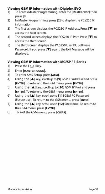
Viewing GSM IP Information with Digiplex EVO1) To access Master Programming, enter the [MASTER CODE] then
press [0].2) In Master Programming, press [2] to display the PCS250 IP
information.3) The first screen displays the PCS250 IP Address. Press [] to
access the next screen. 4) The second screen displays the PCS250 IP Port. Press [] to
access the third screen. 5) The third screen displays the PCS250 User PC Software
Password. If you press [] again, the Exit Message will be displayed.
Viewing GSM IP Information with MG/SP / E-Series1) Press the [ ] key.2) Enter [MASTER CODE].3) To enter SMS Setup, press [ARM].4) Using the [] key, scroll up to [9] GSM IP Address and press
[ENTER]. To return to the GSM menu, press [ENTER].5) Using the [] key, scroll up to [10] GSM IP Port and press
[ENTER]. To return to the GSM menu, press [ENTER].6) Using the [] key, scroll up to [11] GSM PC Password
(Future use). To return to the GSM menu, press [ENTER].7) Using the [] key, scroll up to [12] Site Name. To return to
the GSM menu, press [ENTER].8) To exit the GSM menu, press [CLEAR].

Page 38 Text Messages
Chapter 8: Text MessagesThe following table lists all pre-defined text messages that can be sent. These messages follow the 8-bit or 16-bit SMS protocol and include the elements from the information column. The messages will also use the labels programmed in the system for the area name, zone name, user name, and module name.
Alarm MessagesMessage Information*Alarm cancelled 1-2-3Alarm cancelled with remote 1-2-3Alarm cancelled through Internet 1-2-3Alarm cancelled through End-User PC Software 1-2-3Alarm cancelled through Voice Module (Phone) 1-2-3Alarm cancelled through SMS 1-2-3Alarm cancelled with keyswitch 1-2- 4Alarm cancelled through Installer PC Software 1, 2ALARM 1-2-3FIRE ALARM 1-2-3DURESS ALARM 1-2-3PANIC ALARM 1-2-3MEDICAL PANIC ALARM 1-2-3FIRE PANIC ALARM 1-2-3PARAMEDIC PANIC ALARM 1-2-3GSM/GPRS module: Tamper Alarm 1
Information Index1: Date and Time2: Area Name3: Zone / User / Module Name4: ID5: Module Serial Number
*

Text Messages Page 39
Arming/Disarming MessagesMessage Information*Arming 1-2-3Arming with remote 1-2-3Arming through internet 1-2-3Arming through end-user PC software 1-2-3Arming through voice module (phone) 1-2-3Arming through SMS 1-2-3Arming with keyswitch 1-2- 4Arming through Installer PC software 1-2One-touch arming 1-2Auto-arming 1-2Disarming 1-2-3Disarming with remote 1-2-3Disarming through internet 1-2-3Disarming through end-user PC software 1-2-3Disarming through voice module (phone) 1-2-3Disarming through SMS 1-2-3Disarming with keyswitch 1-2- 4Disarming through Installer PC software 1-2
Information Index1: Date and Time2: Area Name3: Zone / User / Module Name4: ID5: Module Serial Number
*

Page 40 Text Messages
Trouble Event MessagesMessage Information*AC power failure on control panel 1Battery failure on control panel 1Bell overload on control panel 1Bell disconnected from control panel 1Phone line trouble on control panel 1Pager communication from control panel failed 1- 4Central station communication from control panel failed 1- 4Voice communication from control panel failed 1Installer PC communication from control panel failed 1Date and time loss on control panel 1RF interference detected on system's wireless communication
1
Tamper trouble on module 1-3- 5Phone line trouble on module 1-3- 5Central station communication from module failed 1-3- 5Printer module trouble 1-3- 5AC power failure on bus or wireless module 1-3- 5Battery failure on bus or wireless module 1-3- 5Auxiliary power overload on bus or wireless module 1-3- 5Missing module 1-3- 5Tamper trouble on zone 1-2-3-5Trouble on fire zone 1-2-3-5Low battery on wireless zone 1-2-3-5Missing wireless zone (supervision loss) 1-2-3-5Auxiliary power overload on control panel 1Communication with GSM network lost 1GSM communication with control panel lost 1GSM/GPRS module: Tamper Trouble 1GSM/GPRS module: Please check inactive SIM card # connectivity
1
Trouble on module - direct light 1-3-5Trouble on module - bus voltage trouble 1-3-5Trouble on module - self-test failure 1-3-5Zone anti-mask (transparency or proximity) 1-2-3-5Zone anti-mask (dirty lens) 1-2-3-5
Information Index1: Date and Time2: Area Name3: Zone / User / Module Name4: ID5: Module Serial Number

Text Messages Page 41
Trouble Restore Messages
UC300 MessagesIf your PCS250 is connected to an UC300 Universal Converter, the SMS messages will be different from non-connected units. The following table lists all pre-defined text messages that can be sent. These messages follow the 8-bit or 16-bit SMS protocol and include the elements fro m the information column. The messages will also use the labels programmed in the system for the area name, zone name, user name, and module name.
Message Information*AC power restored on control panel 1Battery power restored on control panel 1Bell restored on control panel 1Bell connected on control panel 1Phone line restored on control panel 1Central station communication from control panel restored
1-4
Date and time restored on control panel 1System wireless communication restored 1Tamper restored on module 1-3-5Phone line restored on module 1-3-5Central station communication from module restored 1-3-5Printer module restored 1-3-5AC power restored on bus or wireless module 1-3-5Battery power restored on bus or wireless module 1-3-5Auxiliary power restored on bus module 1-3-5Missing module restored 1-3-5Tamper restored on module 1-2-3-5Fire zone restored 1-2-3-5Battery on wireless zone restored 1-2-3-5Wireless zone restored 1-2-3-5Auxiliary power restored on control panel 1Communication with GSM network restored 1GSM communication with control panel restored 1GSM/GPRS module: SIM card # connectivity restore 1GSM/GPRS module: Tamper Restore 1GSM/GPRS module: SIM card # connectivity restore 1SIM Card initializing, please try again in # minutes 1Trouble on module - direct light restore 1-3-5Trouble on module - bus voltage trouble restore 1-3-5Trouble on module - self-test failure restore 1-3-5Zone anti-mask (transparency or proximity) restore 1-2-3-5Zone anti-mask (dirty lens) restore 1-2-3-5

Page 42 Text Messages
UC300 Alarm MessagesMessage Information*Medical alarm 1-2-3Personal emergency alarm 1-2-3Fail to report in 2-3Fire alarm 1-2-3Smoke alarm 1-2-3Combustion alarm 1-2-3Water Flow alarm 1-2-3Heat alarm 1-2-3Pull Station alarm 1-2-3Duct alarm 1-2-3Flame alarm 1-2-3Near alarm 1-2-3Panic alarm 1-2-3Duress alarm 1-2-3Silent alarm 1-2-3Audible alarm 1-2-3Duress - access granted alarm 1-2-3Duress - egress granted 1-2-3Burglar alarm 1-2-3Perimeter alarm 1-2-3Interior alarm 1-2-324 Hr. alarm 1-2-3Entry/Exit alarm 1-2-3Day/Night alarm 1-2-3Outdoor alarm 1-2-3Tamper alarm 1-2-3Near alarm 1-2-3Intrusion verifier alarm 2-3General alarm 2-3Polling loop open alarm 2-3Polling loop short alarm 2-3Sensor tamper 1-2-3Expansion module failure alarm 2-3Silent burglary 1-2-3Sensor supervision failure alarm 1-2-3
Information Index1: Zone / User 2: Area3:Date and Time

Text Messages Page 43
UC300 Arming/Disarming Messages
UC300 Trouble Messages
Message Information*Arm/disarm 2-3Arm/disarm by user 1-2-3Group arm /disarm 2-3Automatic arm /disarm 2-3Remote arm/disarm 2-3Quick arm/disarm 2-3Keyswitch arm/disarm 1-2-3Stay arm/disarm 2-3Keyswitch stay arm/disarm 2-3Exception arm /disarm 1-2-3Early arm /disarm 1-2-3Late arm /disarm 1-2-3Re-arm after alarm arm /disarm 2-3
Message Information*24 Hr. non-burglary 1-2-3Gas detection 1-2-3Refrigeration 1-2-3Loss of heat 1-2-3Water leakage 1-2-3Foil break 1-2-3Day trouble 1-2-3Low bottled gas level 1-2-3High temp 1-2-3Low temp 1-2-3Loss of air flow 1-2-3Carbon monoxide detected 1-2-3Tank level 1-2-3Fire supervisory 1-2-3Low water pressure 1-2-3Low CO2 1-2-3Gate valve sensor 1-2-3Low water level 1-2-3
Information Index1: Zone / User 2: Area3:Date and Time

Page 44 Text Messages
Pump activated 1-2-3Pump failure 1-2-3System trouble 2-3AC loss 2-3Low system battery 2-3RAM checksum bad 2-3ROM checksum bad 2-3System reset 2-3Panel program changed 2-3Self-test failure 2-3System shutdown 2-3Battery test failure 2-3Ground fault 2-3Battery missing/dead 2-3Power supply over current 2-3Engineer reset 2-3Sounder/Relay troubles 2-3Bell 1 2-3Bell 2 2-3Alarm relay 2-3Trouble relay 2-3Reversing relay 2-3Notification appliance ckt. #3 2-3Notification appliance ckt. #4 2-3System peripheral troubles 2-3Polling loop open 2-3Polling loop short 2-3Expansion module failure 2*-3Repeater failure 2-3Local printer paper out 2-3Local printer failure 2-3Expansion module DC loss 1-2-3Expansion module low battery 2-3Expansion module reset 1-2-3Expansion module tamper 2*-3Expansion module AC loss 2-3Expansion module self-test fail 1-2-3RF receiver jam detect 2-3Communication troubles 2*-3Telco 1 fault 2*-3Telco 2 fault 2-3Long range radio 2-3Fail to communicate 2*-3Loss of radio supervision 2-3Loss of central polling 2*-3Long range radio VSWR problem 2-3Protection loop trouble 2-3
Message Information*

Text Messages Page 45
Protection loop trouble 2-3Protection loop open 2-3Protection loop short 2-3Fire trouble 2-3Exit error alarm (zone) 2-3Panic zone trouble 1-2-3Hold-up zone trouble 1-2-3Swinger trouble 1-2-3Cross-zone trouble 1-2-3Sensor trouble 1-2-3Loss of supervisory - FR 1-2-3Loss of supervisory - RPM 1-2-3Sensor tamper 1-2-3RF transmitter low battery 1-2-3Smoke detector high sensitivity 1-2-3Smoke detector low sensitivity 1-2-3Intrusion detector high sensitivity 1-2-3Intrusion detector low sensitivity 1-2-3Sensor self-test failure 1-2-3Sensor watch trouble 1-2-3Drift compensation error 1-2-3Maintenance alert 1-2-3Late to open 2-3Late to close 2-3Auto-arm failure trouble 2-3Partial arm trouble 2-3Exit error 1-2-3User on premises 1-2-3Recent close 2-3Wrong code entry 2-3Legal code entry 2-3Auto-arm time extended trouble 1-2-3Panic alarm reset 2-3Service on / off premises 2-3
Message Information*
Information Index1: Zone / User 2: Area3:Date and Time
*: Module ID will be reported.

Page 46 Text Messages
UC300 Trouble Restore MessagesMessage Information*24 Hr. non-burglary restore 1-2-3Gas detection restore 1-2-3Refrigeration restore 1-2-3Loss of heat restore 1-2-3Water leakage restore 1-2-3Foil break restore 1-2-3Day trouble restore 1-2-3Low bottled gas level restore 1-2-3High temp restore 1-2-3Low temp restore 1-2-3Loss of air flow restore 1-2-3Carbon monoxide detected restore 1-2-3Tank level restore 1-2-3Fire supervisory restore 1-2-3Low water pressure restore 1-2-3Low CO2 restore 1-2-3Gate valve sensor restore 1-2-3Low water level restore 1-2-3Pump activated restore 1-2-3Pump failure restore 1-2-3System trouble restore 2-3AC loss restore 2-3Low system battery restore 2-3RAM checksum bad restore 2-3ROM checksum bad restore 2-3System reset restore 2-3Panel program changed 2-3Self-test failure restore 2-3System shutdown restore 2-3Battery test failure restore 2-3Ground fault restore 2-3Battery missing/dead restore 2-3Power supply over current restore 2-3Engineer reset restore 2-3Sounder/Relay troubles restore 2-3Bell 1 restore 2-3Bell 2 restore 2-3Alarm relay restore 2-3Trouble relay restore 2-3Reversing relay restore 2-3Notification appliance ckt. #3 restore 2-3Notification appliance ckt. #4 restore 2-3System peripheral troubles restore 2-3Polling loop open restore 2-3Polling loop short restore 2-3

Text Messages Page 47
Expansion module failure restore 2*-3Repeater failure restore 2-3Local printer paper out restore 2-3Local printer failure restore 2-3Expansion module DC loss restore 1-2-3Expansion module low battery restore 2-3Expansion module reset restore 1-2-3Expansion module tamper restore 2-3Expansion module AC loss restore 2-3Expansion module self-test fail restore 1-2-3RF receiver jam detect restore 2-3Communication troubles restore 2*-3Telco 1 fault restore 2*-3Telco 2 fault restore 2-3Long range radio restore 2-3Fail to communicate restore 2*-3Loss of radio supervision restore 2-3Loss of central polling restore 2*-3Long range radio VSWR problem restore 2-3Protection loop trouble restore 2-3Protection loop trouble restore 2-3Protection loop open restore 2-3Protection loop short restore 2-3Fire trouble restore 2-3Exit error alarm (zone) restore 2-3Panic zone trouble restore 1-2-3Hold-up zone trouble restore 1-2-3Swinger trouble restore 1-2-3Cross-zone trouble restore 1-2-3Sensor trouble restore 1-2-3Loss of supervisory - FR restore 1-2-3Loss of supervisory - RPM restore 1-2-3Sensor tamper restore 1-2-3RF transmitter low battery restore 1-2-3Smoke detector high sensitivity restore 1-2-3Smoke detector low sensitivity restore 1-2-3Intrusion detector high sensitivity restore 1-2-3Intrusion detector low sensitivity restore 1-2-3Sensor self-test failure restore 1-2-3Sensor watch trouble restore 1-2-3Drift compensation error restore 1-2-3Maintenance alert restore 1-2-3Late to open restore 2-3Late to close restore 2-3Auto-arm failure trouble restore 2-3Partial arm trouble restore 2-3Exit error restore 1-2-3
Message Information*

Page 48 Text Messages
User on premises 1-2-3Recent close 2-3Wrong code entry 2-3Legal code entry 2-3Auto-arm time extended trouble 1-2-3Panic alarm reset 2-3Service on / off premises 2-3
Message Information*
Information Index1: Zone / User 2: Area3:Date and Time
*: Module ID will be reported.

Page 49 Text Messages
IndexAAccess Point Name .............................................................................. 20Alarm Messages ............................................................................. 38, 42Antenna ...................................................................................................... 9
bandwidth .......................................................................................9extension ...................................................................................... 18installation ................................................................................... 18
APNpassword ...................................................................................... 20user name ..................................................................................... 20
Arm/Disarm ............................................................................................ 29messages ...................................................................................... 39
Audio jack ...................................................................................................6
BBackup phone number ...................................................................... 22Backup reporting ..............................................................................9, 25Bandwidth saver mode ...................................................................... 19
CCancel SMS ............................................................................................. 37Communicating Using Text Messages ......................................... 19Communication loss ..............................................................................7Compatibility ............................................................................................5Configuring the PCS250 ..................................................................... 19Consumption ............................................................................................9Control panel ............................................. 4, 8, 10, 12, 15, 20, 23, 24
presence ....................................................................................... 34programming .............................................................................. 26reporting events ........................................................................ 28
CVT485 ..........................................................................................4, 15, 16
DDefault volume ...................................................................................... 15Digiplex EVO ................................................................................... 35, 37Disarming messages .................................................................... 39, 43Domain name ........................................................................................ 30Dual SIM card ............................................................................................8
EE55 ................................................................................................................5E65 ................................................................................................................5EN certification .........................................................................................9Encryption ..................................................................................................9End-user SMS programming ............................................................ 35Event Call Options ................................................................................ 36EVO ....................................................................................... 22, 23, 24, 27EVO Series ............................................................................................... 25EVO192 ........................................................................................................5EVO48 ..........................................................................................................5External power input ................................................................... 15, 16

Index Page 50
FFirmware upgrades .............................................................................. 33Forwarding SMS Messages ............................................................... 20Front cover .............................................................................................. 10
GGPRS ........................................................................................7, 12, 19, 28
channel .......................................................................................... 25network ......................................................................................... 20remote access ............................................................................. 29reporting ....................................................................................... 23
Ground ..................................................................................................... 15GSM .........................................................................................7, 12, 19, 28
cell phone network ................................................................... 34connection LED .......................................................................... 34network connection loss ........................................................ 34reporting ....................................................................................... 22reporting options ...................................................................... 19volume .......................................................................................... 16
GSM vs. GPRS Connections ............................................................... 12GSM/GPRS modem .............................................................................. 25
IIncluded Items ..........................................................................................5Internet failure ....................................................................................... 25IP Address ................................................................................................ 36IP Port ....................................................................................................... 36IPR512 GPRS/IP Monitoring Receiver ..................................... 23, 27IPRS-7 ........................................................................................................ 25
KK641 ..............................................................................................................5K641R ...........................................................................................................5Knockout holes ..................................................................................... 18
LLabels ................................................................................................. 38, 41Landline
backup ........................................................................................... 22primary .......................................................................................... 22
Languages ............................................................................................... 29LED ................................................................................................................6LED Feedback ...........................................................................................7Light-emitting diodes. See LEDList of SMS commands ....................................................................... 29Loss of GSM service ............................................................................. 34
MMaster Programming .......................................................................... 35MG series ....................................................................................................5MG/SP / E-Series ............................................................................. 35, 37MG/SP/E .............................................................................. 22, 23, 24, 27Module supervision ............................................................................. 34

Page 51 Text Messages
NNEware ..................................................................................................... 32
OOperating Temperature ........................................................................9
PPCS250 ........................................................................................................1
communication loss ....................................................................7configuration .............................................................................. 19LED feedback .................................................................................7overview ..........................................................................................6reset ................................................................................................ 29specifications .................................................................................9
Phone number ......................................................4, 15, 29, 32, 35, 36Power input ...............................................................................................9Power supply ......................................................................................... 15
connections ................................................................................. 15Pre-defined text messages ........................................................ 38, 41Primary phone number ...................................................................... 22Private Network .................................................................................... 33Programming phone numbers ....................................................... 20Provider redundancy .............................................................................8Public Network ...................................................................................... 32
RReceiver settings ................................................................................... 24Receiving Text Messages ................................................................... 20Registration parameters .................................................................... 20Remote access ....................................................................................... 22Required/Optional Items ......................................................................5Reset .......................................................................................................... 29Rod antenna ........................................................................................... 18RS485 link ............................................................................................4, 16RX ............................................................................................................... 21
SSerial cable .............................................................................................. 12Serial cable connector ........................................................................ 12Serial port ......................................................................................... 13, 28Signal strength ..................................................................................7, 30SIM card .......................................................................................... 7, 8, 19
connection ................................................................................... 10error ...................................................................................................7installation ................................................................................... 10socket ............................................................................................. 33
SMSbackup reporting ....................................................................... 25commands ............................................................................ 20, 29languages ..................................................................................... 28messages ........................................................................ 16, 29, 34phone number special characters ....................................... 36protocol ............................................................................................9

Page 52 Index
text message format ................................................................ 29SMS commands
APN ................................................................................................. 30APN password ............................................................................. 30APN user ....................................................................................... 30arm/disarm .................................................................................. 31clear APN ...................................................................................... 30clear domain name ................................................................... 30disable bandwidth saver mode ............................................ 30enable bandwidth saver mode ............................................ 30GPRS remote access ................................................................. 29IP address ..................................................................................... 29reset PCS250 ................................................................................ 29set domain name ....................................................................... 30signal strength ............................................................................ 30volume .......................................................................................... 30
SP Series ...............................................................................................5, 25Specifications ....................................................................................... 8, 9Supervision ............................................................................................. 34Switching reporting methods ......................................................... 12System Components ..............................................................................6System features ........................................................................................4
TTamper switch ..................................................................................... 6, 8TCP/IP password ................................................................................... 32Technical specifications ........................................................................9Text message notification ................................................................. 28Text Messages ....................................................................................... 19Text messages ................................................................................ 38, 41Trouble event messages ...................................................... 40, 43, 46Trouble restore messages ................................................................. 41Troubles ................................................................................................... 23
UUC300 Connection ............................................................................... 14UC300 SMS messages ......................................................................... 41Upload/download ......................................................................... 32, 33User PC Software Password .............................................................. 36
VVDMP3............................................................................................... 11, 15
connections ................................................................................. 15Viewing GSM IP information ............................................................ 37VOLOUT ................................................................................................... 15Volume ..................................................................................................... 15VSMS command .................................................................................... 25
WWait for call ............................................................................................. 33Wall-Mount Installation ...................................................................... 18Wire length ............................................................................................. 15

Notes
______________________________________________________________________________________________________________________________________________________________________________________________________________________________________________________________________________________________________________________________________________________________________________________________________________________________________________________________________________________________________________________________________________________________________________________________________________________________________________________________________________________________________________________________________________________________________________________________________________________________________________________________________________________________________________________________________________________________________________________________________________________________________________________________________________________________________________________________________________________________________________________________________________________________________________________________________________________________________________________________________________________________________________________________________________________________________________________________________________________________________________________________________________________________________________________________________________________________________________________________________________________________________________________________________________________________________________________________________________________________________________________________________________________________________________________________________________________________________________________________________________________________________________________________________________________________________________________________________________________________________________________________________________________________________________________________________________________________________

WarrantyFor complete warranty information, please visit www.paradox.com/terms. Your use of the Paradox product signifies your acceptance of all warranty terms and conditions. Paradox, Spectra, EVO, Digiplex and BabyWare are trademarks or registered trademarks of Paradox Security Systems (Bahamas) Ltd. or its affiliates in Canada, the United States and/or other countries. For the latest product approvals, such as UL and CE, please visit www.paradox.com. © 2014 Paradox Security Systems Ltd. All rights reserved. Specifications may change without prior notice.
PatentsOne or more of the following US patents may apply: 7046142, 6215399, 6111256, RE40650, 5920259, 5886632, 5571803 and RE39406 and other pending patents may apply. Canadian and international patents may also apply.


For certified Paradox distributors:For technical support in Canada or the U.S., call 1-800-791-1919,
Monday to Friday from 8:00 a.m. to 8:00 p.m. EST. For technical support outside Canada and the U.S.,
call 00-1-450-491-7444, Monday to Friday from 8:00 a.m. to 8:00 p.m. EST.
To learn more about the complete line of Paradox products, please visit www.paradox.com.