
The Visual Computer manuscript No. Daniel Cohen-Or ...
9
The Visual Computer manuscript No. (will be inserted by the editor) Andrei Sharf · Marina Blumenkrants · Ariel Shamir · Daniel Cohen-Or SnapPaste: An Interactive Technique for Easy Mesh Composition Abstract Editing and manipulation of existing 3D geomet- ric objects are means to extend their repertoire and promote their availability. Traditionally, tools to compose or manipu- late objects defined by 3D meshes are in the realm of artists and experts. In this paper, we introduce a simple and effec- tive user interface for easy composition of 3D mesh-parts for non-professionals. Our technique borrows from the cut-and- paste paradigm where a user can cut parts out of existing objects and paste them onto others to create new designs. To assist the user attach objects to each other in a quick and simple manner, many applications in computer graphics support the notion of “snapping”. Similarly, our tool allows the user to loosely drag one mesh part onto another with an overlap, and lets the system snap them together in a graceful manner. Snapping is accomplished using our Soft-ICP algo- rithm which replaces the global transformation in the ICP algorithm with a set of point-wise locally supported trans- formations. The technique enhances registration with a set of rigid to elastic transformations that account for simultane- ous global positioning and local blending of the objects. For completeness of our framework, we present an additional simple mesh-cutting tool, adapting the graph-cut algorithm to meshes. Keywords Interactive Tools · User-Interface · Cut-and- Paste · Snapping · Meshes A. Sharf Tel Aviv University Tel.: +972-3-6405360 E-mail: [email protected] M. Blumenkrants The Interdisciplinary Center Herzliya A. Shamir The Interdisciplinary Center Herzliya D. Cohen-Or Tel Aviv University Fig. 1 Snapping allows easy pasting of mesh parts by loosely posi- tioning them close to their target, and letting the system snap them together. 1 Introduction The creation of digital geometric objects for graphics, en- gineering, games or motion pictures is a difficult and of- ten expensive process. Despite recent impressive progress in automatic modeling and reconstruction, a fair amount of geometric processing is always done manually. Experts use modeling software for the design and creation of 3D mod- els. However, such software require meticulous work, and must be driven by a professional skilled artist or engineer to produce correct and visually pleasing results. Recently, a growing number of works have been targeted at simplifying
Transcript of The Visual Computer manuscript No. Daniel Cohen-Or ...

The Visual Computer manuscript No.(will be inserted by the editor)
Andrei Sharf · Marina Blumenkrants · Ariel Shamir · Daniel Cohen-Or
SnapPaste: An Interactive Technique for Easy Mesh Composition
Abstract Editing and manipulation of existing 3D geomet-ric objects are means to extend their repertoire and promotetheir availability. Traditionally, tools to compose or manipu-late objects defined by 3D meshes are in the realm of artistsand experts. In this paper, we introduce a simple and effec-tive user interface for easy composition of 3D mesh-parts fornon-professionals. Our technique borrows from the cut-and-paste paradigm where a user can cut parts out of existingobjects and paste them onto others to create new designs.To assist the user attach objects to each other in a quickand simple manner, many applications in computer graphicssupport the notion of “snapping”. Similarly, our tool allowsthe user to loosely drag one mesh part onto another with anoverlap, and lets the system snap them together in a gracefulmanner. Snapping is accomplished using our Soft-ICP algo-rithm which replaces the global transformation in the ICPalgorithm with a set of point-wise locally supported trans-formations. The technique enhances registration with a setof rigid to elastic transformations that account for simultane-ous global positioning and local blending of the objects. Forcompleteness of our framework, we present an additionalsimple mesh-cutting tool, adapting the graph-cut algorithmto meshes.
Keywords Interactive Tools · User-Interface · Cut-and-Paste · Snapping · Meshes
A. SharfTel Aviv UniversityTel.: +972-3-6405360E-mail: [email protected]
M. BlumenkrantsThe Interdisciplinary Center Herzliya
A. ShamirThe Interdisciplinary Center Herzliya
D. Cohen-OrTel Aviv University
Fig. 1 Snapping allows easy pasting of mesh parts by loosely posi-tioning them close to their target, and letting the system snap themtogether.
1 Introduction
The creation of digital geometric objects for graphics, en-gineering, games or motion pictures is a difficult and of-ten expensive process. Despite recent impressive progressin automatic modeling and reconstruction, a fair amount ofgeometric processing is always done manually. Experts usemodeling software for the design and creation of 3D mod-els. However, such software require meticulous work, andmust be driven by a professional skilled artist or engineerto produce correct and visually pleasing results. Recently, agrowing number of works have been targeted at simplifying

2 Andrei Sharf et al.
the interaction and manual manipulation of 3D objects to en-able simple and interactive editing by non-professionals [15,13,14,22].
In this work we focus on a user interface operation borrowedfrom computer editing applications – the cut-and-paste op-eration. In the context of direct manipulation, cut-and-pasteis used as a metaphor for cutting and connecting mesh partsand surfaces. However, in current mesh editing applicationthis can become a complicated procedure. The user is re-quired to carefully cut a designated surface-part, place itnear the other surface in an exact position, define the cor-respondence between boundary parts, stitch them together,and possibly add or remove outliers manually. These oper-ations may need to be repeated several times to generate anatural merge between the two surfaces. Our goal is to definean easy-to-use tool which supports cut-and-paste of surfacemeshes as a simple, natural and intuitive operation.
To support simple cutting, we present a simple mesh cut-ting tool based on a graph-cut procedure. This tool enablesthe user to separate parts from a mesh simply by drawing acutting stroke even from a single viewpoint. The stroke pathis projected on the mesh and automatically closed to forma loop. This loop is used to define the approximated areaof the cut. The final cut is created using a feature-sensitivegraph-cut algorithm.
To support simple pasting, we turn to a very useful and ef-fective notion in graphics applications - the notion of snap-ping. Snapping is often used to alleviate the user’s need toexactly position shapes before connecting them. Using snap-ping, shapes are automatically attracted to specific locations(grid) or to other shapes. By extending this notion to 3Dsurfaces, our tool snaps two mesh parts together with a lo-cal graceful warp that respects their initial relative position.Our snapping tool allows even little kids to connect 3D meshparts easily (Figure 2): the user chooses a mesh part, looselydrags and rotates it to an approximate position close to thetarget mesh and releases. The part automatically snaps to thetarget mesh. There is no need for precise positioning of partsin 3D, no need to delicately separate mesh parts and defineexact boundaries and no need to set or tune any parameters.Snapping merges gracefully any two valid mesh parts withboundaries, as long as they have an overlapping region. Werefer to such overlapping region as the snapping region.
In effect, snapping involves two parts: relative global posi-tioning and local blending of the two surface meshes. We usepoint-wise local rigid transformations with varying supportto achieve both tasks. We base our technique on the clas-sic iterative closest point (ICP) algorithm which supportsrigid body transformations, and extend it toward a more gen-eral transformation by defining a novel soft-ICP algorithm.While the original ICP algorithm searches for a global trans-formation to register two point sets, we use a series of global-to-local transformations with differing supports for position-ing and blending the two objects.
Fig. 2 Mesh-snapping allows even eight years old children to compose3D mesh parts easily.
The support neighborhood size, defining the local transfor-mation of each point, changes depending both on the posi-tion of the point on the surface and on time (i.e. the iterationnumber). Consequently, the transition between global to lo-cal, thus from rigid to soft is defined in a gradual manneracross the surface and through the iterations. Points whichare far from the snapping region undergo a more rigid dis-placement common to larger neighborhoods. Points whichare closer to the snapping region move with locally rigidtransformations that together form a soft-warp of the sur-face at the region where the two surfaces overlap. This seriesof transformations creates a smooth transition that scales,aligns and merges the two surfaces together.
Once the two surfaces are snap together, the overlapping re-gion connecting the two parts is re-meshed based on [25]to create one valid mesh. Examples of snapping of generalcylindrical shapes can be seen in Figure 1, where the Felineis transformed into a Griffin by loosely pasting parts of aneagle’s head and legs. Disk-like shapes are seen in Figure 9,where the sphinx face is replaced. More examples can befound in the results section and in the video attached.
The main contributions of this paper are as follows:
– We extend the cut-and-paste notion to 3D meshes.– We define a snapping method for two mesh parts to assist
easy pasting and composition of 3D objects. The snap-ping solves both positioning and blending of the two sur-faces by defining a novel soft-ICP algorithm.
– We define an easy mesh cutting tool based on graph cuts.
2 Background and Related Work
Cut-and-paste is a user-interface paradigm for transferringdata pieces of any kind from a source to a destination. Thecut-paste notion is derived from the traditional practice inmanuscript editing in which paragraphs were literally cut

SnapPaste: An Interactive Technique for Easy Mesh Composition 3
from a page with scissors and physically pasted onto anotherpage. In software system this paradigm has become so uni-versal and general, that most users expect to find it in anyediting and modeling application. Although the basic ideaof extracting data from one part and inserting it back intoanother is simple, there is a need to define the meaning ofcutting and pasting depending on the data and its represen-tation. This is especially true when the data is as complex as3D objects in mesh representation.
Constructive solid geometry (CSG) representation uses Booleanoperations such as subtraction to support cutting and unionto support pasting. Several works have extended these opera-tions to boundary surfaces using different implicit represen-tations. [29] use analytic primitives or skeletal implicit rep-resentation. Point-based representations and level-sets wereused in [21], moving least square surfaces in [31], and parti-tion of unity in [23]. The approach presented in [12] is basedon voxelization, volumetric minimal cuts and stitching tocompose meshes. Nevertheless, most available graphics ob-jects are still defined using explicit meshes where booleanoperations and cut-and-paste are more difficult. Moreover,the relative positioning of the two blended parts still remainsa difficult task, regardless of the representation.
In [4] boolean operations on explicit multi-resolution sur-faces are presented, but with no blending or smoothing be-tween parts. Later, in [5] a cut-and-paste operator is definedmostly for details of implanting and patch embedding, ratherthan composing whole mesh parts. Other works on meshediting deal with direct manipulation and mesh-deformationoperators [18,2,1,26]. Nevertheless, in these works meshcomposition usually needs delicate manual intervention. Forexample in [30] manual intervention is needed to achievecorrespondence between boundaries. In [27], additional stepsof registration, possibly local re-meshing and zipping (fillingin gaps) are required. Similarly, in the system for modeling-by-example [11] the two major challenges in their compo-sition, positioning and attachment, are dealt with by globalrigid positioning using volumetric ICP, and stitching betweentwo predefined conforming (corresponding) contours.
Other approaches are based on joint-parameterization of lo-cal regions on the source and target meshes. In [10], pastingof a source mesh (possibly with high genus) is performedby defining a joint base parameterization to the source andtarget regions, replacing the base mesh region in the targetwith the source base region and then transferring the details.In [16] a combined parameterization is built, when the cor-respondence is defined using ICP, and the pasting operationis implemented by blending the two meshes using morphingbetween the source and target on the target mesh.
For interactive mesh cutting, modeling applications eitherallow explicit specification of the cut position or the useof a lasso tool which needs specific view directions to suc-ceed. Intelligent scissoring was presented in modeling-by-example [11] where a stroke is painted directly on the mesh.This stroke is used to define a neighborhood where the real
cut is then completed to form a loop using a cost functionand a variant of Dijkstra algorithm. Our cutting algorithmuses a similar method to close the loop between the two end-points of the initial stroke. However this is only done to de-fine two separate regions on the mesh. The actual cut is de-fined using a graph cut between the two regions, adhering tosurface features. Graph cuts have been used extensively onimages for segmentation and feature extraction [6,20] andin [17] for automatic partitioning of meshes. A different in-telligent scissoring tool is proposed in [19], where a 2D lineis used to define a plane that cuts the mesh to create an ini-tial loop. The position of this loop is then refined using a 3Dsnake. However, sketching a stroke directly on the mesh hasmore flexibility than a 2D plane, and advancing an activecontour can be more complicated than finding a graph cut
Our work seeks to define a simpler and more effective inter-active tool for easy cut-and-paste in the spirit of a smart andsimple user interface for modeling. Such a tool must supporteasy mesh cutting and address both the positioning and theblending problems when pasting two surface parts together.We focus our efforts on the ease-of-use of such a tool, wheresnapping replaces the usual meticulous work of positioningand connecting two meshes, with an interactive techniquefor pasting.
The rest of the paper is composed as follows. In Section 3we present an overview of our Soft-ICP algorithm for snap-ping, followed by Sections 4 to 6 which describe the Soft-ICP algorithm details. Section 7 describes our simple cuttingtool and in Section 8 we present our data-structure. We showsome results and conclude in Sections 9 and 10.
3 Soft-ICP Algorithm Overview
The definition of our easy pasting tool is based on the abil-ity to automatically snap two mesh parts and compose a sin-gle one. Snapping involves both calculating the relative posi-tion (global alignment) of the composed parts and creating ablend (local deformation) between them. Both of these tasksare addressed by using a new soft-ICP algorithm (Figure 3).The goal of the original Iterative Closest Point (ICP) algo-rithm is to find a registration between two point sets [7,3].The ICP algorithm proceeds in an iterative manner using thefollowing steps:
1. Find a point-wise correspondence between the sets.2. Compute and apply registration on the two sets.3. Check error threshold, and return to first step if needed.
The correspondence and registration steps search for a rigidtransformation, including translation and rotation, that re-duces the sum-of-squared distances between point pairs. Themany variants of the basic algorithm differ in the methodfor selecting and matching the points, the weighting of thecorresponding pairs, the use of pair-rejection criteria, the er-ror metric used and the minimization technique of the er-

4 Andrei Sharf et al.
(a) (b) (c) (d)
Fig. 3 The Soft-ICP algorithm: (a) Starting with one shape placed near another with an overlap, correspondence is computed in the snappingregion (gray region). (b) Transformations are computed point-wise (example shows for 3 points), based on local supporting neighborhoods(colored stripes). (c) The algorithm iteratively computes correspondence and transformations on both shapes until they gracefully blend together.Note the elastic deformation inside the snapping region while details outside rigidly align. (d) For comparison we show the result of applyingthe original ICP algorithm on the two shapes.
ror metric [24]. Nevertheless, most methods still look forone global transformation that registers the two point sets.Our approach is similar to the methods introduced in [28,9]. These methods use a local ICP algorithm for the regis-tration of anatomical 3D data-sets. However, in these workstwo full surfaces are registered and not sub-parts, and staticEuclidean neighborhoods are used. Using such algorithmsfor combining mesh parts will not solve both positioning andblending problems.
The Soft-ICP algorithm solves both global positioning andblending of the two objects simultaneously. The basic ideais that at each iteration, each point pi of the mesh is trans-formed by its own individual transformation Ti. This trans-formation is computed using similar calculations as ICP, buton a local support around pi denoted: N(pi) (Figure 3(b)).The overall effect of applying a different transformation toeach point individually is, that the surface defined by thepoints can undergo non-rigid (elastic) deformations. Sinceneighboring points have overlapping local support, they un-dergo similar transformations, creating a smooth deforma-tion across the surface ((Figure 3(b-c))). We utilize this typeof deformation for snapping the two surfaces together.
The pseudocode of the soft-ICP algorithm is presented inFigure 4. Note that the algorithm is defined for snapping onemesh MA to another MB. In practice, we exchange the rolesof MA and MB after each iteration, creating an almost sym-metric snapping procedure.
4 Snapping Region and Correspondence
The Soft-ICP technique depends on the correspondence amongpoints on both surfaces. To find correspondence, it is impor-tant that the surfaces overlap since the correspondence is de-fined in the overlapping region (Figure 3(a)). If there is toolittle or no overlap between the meshes, i.e. not enough cor-respondence, snapping is not performed. This in turn, willdrive the user to continue dragging or rotating the mesh-partsuntil they overlap and snap.
Procedure: snap MA to MBLet SA and SB be the snapping regions
of MA and MB respectivelyLoop until convergence {
Find correspondence φ of SA to SBFor each point pi in MA {
Find the local neighborhood N(pi)Calculate the transformation Ti
based on φ |N(pi)}For each point pi in MA {
Apply Ti to pi}
}
Fig. 4 The Soft-ICP pseudocode.
To define a snapping region, we assume that the two meshesare valid manifolds and contain two designated boundaryloops. Note that in the case of closed meshes with no bound-aries an additional cutting step should be performed. Fur-thermore, for meshes with multiple boundaries, we take theclosest pair (one from each mesh) to be the designated bound-ary loops.
For each mesh, we find the set of closest points to the othershape boundary loop. Next, we compute the geodesic dis-tance for each point in the set to their own boundary loop.We define the snapping region size R as the maximum of thegeodesic distances. Thus, the sub-mesh within R geodesicdistance from the boundary loop is defined as the snappingregion. Only points within the snapping regions of the twomeshes are used for correspondence computation (see Fig-ures 3(a) and 6).
Let SA and SB be the two snapping regions on the two meshes.For each point pa ∈ SA the corresponding point pb ∈ SB isdefined as: (∀q ∈ SB,D(pa, pb) < D(pa,q)). The distanceD(pa, pb) is a weighted sum of three terms:
w1||pa− pb||+w2 arccos(Na ·Nb)+w3(ca− cb)
The first term is the Euclidean distance between the points.The second term represents the angle difference of the nor-

SnapPaste: An Interactive Technique for Easy Mesh Composition 5
Fig. 5 Differences in the speed of the pasting gesture: colors of theheads denote the dragging speed, the darker the color, the more slowlythe positioning is. The snapping process has more freedom in relativepositioning as the pasting is faster. Dragging the shapes slowly causesthe shapes to merge with little change in the global position.
mals Na and Nb at the points, and the third is the differencein the local Gaussian curvatures ca,cb at the points. Theweights of the three terms are user defined and in practicewe use w1 = 0.6,w2 = 0.2,w3 = 0.2. This means that onlypoint-pairs which are both close and similar in local shapefeatures are matched.
5 Supporting Neighborhoods
The transformation Ti of each point pi is computed based ona local geodesic neighborhood around pi. We define the geo-desic neighborhood of pi: Nr(pi), as the set of mesh verticesthat are within r geodesic distance from pi. Thus, for com-putation of Ti, we consider only the local correspondence φthat is inside the geodesic neighborhood Nr of pi: φ |Nr(pi)(Figure 3(b)).
These supporting neighborhoods Nr(pi) change their size rdepending on the distance of the points from the snappingregion and on the iteration. For each point pi we start from amaximal neighborhood that includes all φ . As the iterationsprogress, the neighborhood of the point is reduced as a func-tion of both iteration t and the proximity of the point to thesnapping region (its boundary loop). For a point pi the sizer of Nr(pi) is calculated as follows:
ri = R · e−[(t·k/di)2]
Where R is the snapping region size, t is the iteration (1 ≤t ≤ tmax) and di is the geodesic distance of pi to the snappingregion (its boundary loop). Note that for points outside thesnapping region, we additionally offset ri with their distanceto the snapping region. Thus, the supporting neighborhoodis always contained (fully or partially) inside the snappingregion (in Figure 3(b) the yellow stripe).
Fig. 6 Snapping region (left-top before and left-bottom after snap-ping), is remeshed (right) while constraining its boundaries to conformto connectivity of each mesh, creating one valid mesh after the snap.
Points which are far from the snapping region have largerneighborhoods, hence their transformation is mostly a globalrigid one. The closer the point is to the snapping region,the smaller its neighborhood, thus resulting in more locally-rigid transformation. The displacements of the meshes area series of rigid-to-elastic transformations which depend ontime (iterations) and the geodesic distance to the snappingregion (Figure 3(c)).
The elasticity constant k (1 ≤ k ≤ kmax) governs the trade-off between movement and accuracy. It is used to distin-guish between slow pasting gestures, when high accuracyis needed (k = kmax) and fast pasting gestures, when largemovement is allowed (k = 1). The interactive snapping processhas more freedom in the relative positioning (rigid align-ment) as the interactive pasting is faster. Aligning the shapesslowly causes the shapes to merge with little change in theglobal position, as indicated by the brown heads in Figure 5.
6 Transformation Calculation
Once correspondence φ and local neighborhoods Nr(pi) aredefined, we compute the transformation Ti =(R,T ,S ) basedon φ |Nr(pi); First, scale S is found using the oriented bound-ing boxes of Nr(pi) and its corresponding points. TranslationT among the two point sets is found using center-of-massalignment. Finally rotation R is determined using standardSVD minimization:
∑<pa,pb>∈φ |Nr(pa)
||(R(pa)+T )− pb||2
To create a softer transition and find a better fit between thesurfaces we apply the soft-ICP transformations in a gradualmanner. In the first iterations we scale, translate and rotate
6 Andrei Sharf et al.
(a) (b) (c) (d)
Fig. 7 Cutting a mesh: (a) The user marks a path on the mesh (b) Thepath is automatically closed (c) The min-cut separates the mesh intotwo parts (d) The mesh is cut.
(using quaternions) only a portion (li) of the way. As itera-tions progress (and the surfaces get closer), this portion in-creases locally until we use the full transformation:
li = t/tmax
The snapping algorithm results in the two shape meshes fullyoverlayed in the snapping regions. To create a valid mesh,a post processing step of local re-meshing is required forthe two overlayed meshes. We used the re-meshing algo-rithm with boundary constraints from [25] (Figure 6). Nev-ertheless, any local re-meshing algorithm can be used to re-triangulate the snapping regions connecting the two meshes.
7 Mesh Cutting
To complete our cut-and-paste framework for 3D meshes wehave developed a simple and effective cutting tool. The mainidea behind our approach, is to assist the user to create cor-rect and effective cuts while still preserving a simple stroke-based natural user interface.
Our mesh cutting algorithm has three major parts (Figure 7):1. Loop completion, 2. Graph cut, and 3. Cut smoothing. Tostart a new cut, the user “paints” a stroke near the desiredposition of the cut. The positions of the mouse are projectedonto the surface and a set of faces are created to representthe stroke.
Using the longest component of consecutive faces of thestroke denoted by S, the first step is to complete a wholeloop from its two end-faces. We use Dijkstra shortest pathalgorithm using the following cost function between neigh-boring faces fi and f j:
c( fi, f j) = g( fi, f j)+ ID( f j,S)+ND(n j,S)
Where g( fi, f j) is the geodesic distance between fi and fb.
ID( f j,S) is the inverse geodesic distance from f j 6∈ S to thestroke S:
ID( f j,S) = ∑f∈S
1g( f , f j)
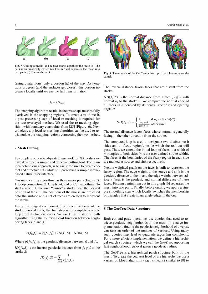
Fig. 8 Three levels of the GeoTree anisotropic patch hierarchy on thecamel.
The inverse distance favors faces that are distant from thestroke.
ND( f j,S) is the normal distance from a face f j 6∈ S withnormal n j to the stroke S. We compute the normal cone ofall faces in S denoted by its central vector v and openingangle α .
ND( f j,S) =
{1 if n j · v≥ cos(α)
n j ·v+1cos(α)+1 otherwise
The normal distance favors faces whose normal is generallyfacing in the other direction from the stroke.
The computed loop is used to designate two distinct meshsides and a “fuzzy region”, inside which the real cut willpass. Thus, we extend the initial loop of faces to a width ofn triangles to both sides (n is the user defined stroke width).The faces at the boundaries of the fuzzy region in each sideare marked as source and sink respectively.
Next, a weighted graph on the faces is built to represent thefuzzy region. The edge weight to the source and sink is thegeodesic distance to them, and the edge weight between ad-jacent faces is the geodesic and normal difference of thesefaces. Finding a minimum cut in this graph [6] separates themesh into two parts. Finally, before cutting we apply a sim-ple smoothing step which locally switches the membershipof triangles that create sharp angle edges in the cut.
8 The GeoTree Data Structure
Both cut and paste operations use queries that need to re-trieve geodesic neighborhoods on the mesh. In a naive im-plementation, finding the geodesic neighborhood of a vertexcan take an order of the number of vertices. Using manysuch queries may lead to quadratic algorithm complexity.For a more efficient implementation, we define a hierarchi-cal search structure, which we call the GeoTree, supportingfast neighborhood retrieval given a geodesic radius.
The GeoTree is a hierarchical patch structure built on themesh. To create the coarsest level of the hierarchy we use avariant of Lloyd algorithm (e.g., k-means) similar to [8] to

SnapPaste: An Interactive Technique for Easy Mesh Composition 7
Fig. 9 Sphinx’s face lift. A part of the Sphinx’s face is loosely cut out and replaced (left). Snapping aligns and merges the replacing part in anatural manner (right).
partition the mesh into k anisotropic patches of similar size.This creates anisotropic feature-sensitive neighborhoods whichare more coherent to surface attributes. As will be shown,both cutting and snapping gain from this feature.
To build a full matrix of geodesic distances between thepatches in the coarsest level we compute all-pairs shortestpaths between the centers of the patches. Each patch is thenpartitioned recursively to four, creating a quadtree structureon the surface (Figure 8). At each level, we compute for eachnode (i.e., each patch) the distances to the m closest patchesonly, and store them in the node.
The geodesic neighborhood of a point p is approximated bythe union of patches collected from the GeoTree. Given aradius r, and a point p, we find the leaf node in the GeoTreethat contains p. If the radius r is smaller than the m-furthestpatch distance, we collect all patches whose distance is smallerthan r to compose the geodesic neighborhood of p. If the ra-dius r is larger than the m-furthest patch, we go up one levelin the hierarchy and repeat the process. At topmost level, weuse the full matrix of the patch distances.
We utilize our GeoTree hierarchy to accelerate the cuttingprocess. Instead of using all triangles of the mesh we use anadaptive cut in the GeoTree. Far from the fuzzy region weuse the coarse levels of the GeoTree and build the weightedgraph using GeoTree patches. As we get closer to the strokewe use finer levels of the GeoTree patches and finally verynear and inside it we use the triangles.
In the Soft-ICP algorithm, in each iteration we calculate φonce, but for each point we need to find φ |Nr (Section 5).Using the GeoTree, this neighborhood search is supportedin an efficient manner. Furthermore, since anisotropic neigh-borhoods are more coherent to surface attributes, φ |Nr has abias towards similar features matchings-pairs.
9 Results
We have applied our snapping algorithm to various types of3D objects including scanned meshes, CAD and artificialmeshes. We used a Pentium-4, 2.4 GHz, 1G memory withNvidia GeForce-4800 card. Results show high visual qual-ity with an interactive rate of not more than a few secondsper operation (see Table 1, and the supplied video).
Model Number Number Snappingfaces vertices time
hand+camel 96,394 41,856 3.5 sechand+flamingo 79,498 37,954 2.7 sechand+duck 71,594 35,956 2.4 sechand+dinopet 67,870 34,082 2.2 sec
Table 1 Timing results of snap-paste for the puppet show example.The differences depend on the snapping region size and number of soft-ICP iterations. Other pasting examples have similar timing of order ofonly few seconds.
For very large meshes (millions of triangles), we have de-veloped two efficient accelerations: The first, uses GeoTreepatches instead of triangles far from the snapping region.The second, restricts the Soft-ICP computation within a con-stant distance from the snapping region. Mesh parts that arefurther away from this distance will transform using oneglobal rigid transformation.
Due to our anisotropic GeoTree structure (Section 8), ouralgorithm works in a feature sensitive manner, guaranteeingthat the shapes are snapped along similar features. Figure 10shows the snapping of the Gargoyle to the bow of a ship.While the squared like base of the Gargoyle is matched andsnapped to the bow, the features of the models itself undergoonly little deformation due to nearly global transformations.
Figure 11 shows some results of snapping multiple parts to-gether to create new diverse models. In the creation process,no fine cutting or exact positioning of the shapes is required.The objects were loosely dragged in proximity to one an-other and released, and the snapping process took only a fewseconds each time.
Our technique can also handle complex topological shapesand snap multiple boundaries at once. For example, in Fig-ure 12, we compose the tail of the Feline, which containsa hole and two boundaries, to its neck. This simultaneoussnapping can only be achieved by a technique that treats thesurface locally as a soft body and does not require exact po-sitioning. The reason for this is that it is unlikely that the twoboundaries can be fit simultaneously.

8 Andrei Sharf et al.
Fig. 10 Snapping the Gargoyle to the bow of a ship.
Fig. 11 Snapping multiple parts together creates a repertoire of newmodels in a matter of seconds. The mythological Chimera, a puppetshow and a tree created of various parts.
10 Conclusions
In this paper we introduced a cut-and-paste tool which isdesigned for non-professionals. In our framework the userdoes not need to cut nor to position the parts precisely tocompose them. Instead, the system automatically snaps to-gether parts which are overlapping in a graceful manner. Wepresented numerous results obtained using these tools withvery little user effort. The core of our tool is a snapping tech-nique based on a soft-ICP algorithm. Soft-ICP consists of aseries of point-wise locally supported rigid transformations.The local support varies both in time and in space, defining aseries of global to local, and a rigid to elastic transformationthat simultaneously solve both the global positioning and thelocal blending problems.
There are several possible extensions to this work. The de-finition of a snapping operation when no overlap exists isa possible extension. Another, is the definition of an opera-tion semantics when one or both of the snapped parts do notcontain boundary loops. We also believe that the soft-ICP al-gorithm can be beneficial for other related applications. Thisincludes hole-filling, repairing polygonal models, and sur-face registrations. Additionally, we would like to continuepursuing easy-to-use tools for interactive modeling, to facil-itate modeling for both professional and amateurs.
Acknowledgements We would like to thank Carlos E. Scheidegger,Shahar Fleishman and Claudio Silva for providing us the code for lo-cal triangulation with boundary constraints in our remeshing step. Thiswork was supported partly by a grant from the Israeli Ministry of Sci-ence.
References
1. Angelidis, A., Wyvill, G., Cani, M.P.: Sweepers: Swept user-defined tools for modeling by deformation. In: Shape ModelingInternational, pp. 63–73 (2004)
2. Bendels, G.H., Klein, R.: Mesh forging: editing of 3d-meshes us-ing implicitly defined occluders. In: Proceedings on ACM Sym-posium on Geometry Processing, pp. 207–217 (2003)
3. Besl, P.J., McKay, N.D.: A method for registration of 3-d shapes.IEEE Transactions on Pattern Analysis and Machine Intelligence14(2), 239–256 (1992)

SnapPaste: An Interactive Technique for Easy Mesh Composition 9
Fig. 12 Snapping multiple boundaries simultaneously can only be achieved by a technique that treats the surface locally as a soft body and doesnot require exact positioning.
4. Biermann, H., Kristjansson, D., Zorin, D.: Approximate booleanoperations on free-form solids. In: Proceedings of ACM SIG-GRAPH 2001, pp. 185–194 (2001)
5. Biermann, H., Martin, I., Bernardini, F., Zorin, D.: Cut-and-pasteediting of multiresolution surfaces. In: Proceedings of ACM SIG-GRAPH 2002, pp. 312–321 (2002)
6. Boykov, Y., Jolly, M.: Interactive graph cuts for optimal boundary& region segmentation of objects in n-d images. In: InternationalConference on Computer Vision (ICCV), pp. 105–112 (2001)
7. Chen, Y., Medioni, G.: Object modelling by registration of multi-ple range images. Image and Vision Computing 10(3), 145–155(1992)
8. Cohen-Steiner, D., Alliez, P., Desbrun, M.: Variational shape ap-proximation. ACM Transactions on Graphics pp. 905–914 (2004)
9. Feldmar, J., Ayache, N.: Rigid, affine and locally affine registra-tion of free-form surfaces. The International Journal of ComputerVision 18 (1996)
10. Fu, H., Tai, C.L., Zhang, H.: Topology-free cut-and-paste editingover meshes. In: Proceedings of the 3rd International Conferenceon Geometric Modeling and Processing (2004)
11. Funkhouser, T., Kazhdan, M., Shilane, P., Min, P., Kiefer, W., Tal,A., Rusinkiewicz, S., Dobkin, D.: Modeling by example. ACMTransactions on Graphics (SIGGRAPH 2004) pp. 652–663 (2004)
12. Hassner, T., Zelnik-Manor, L., Leifman, G., Basri, R.: Minimal-cut model composition. In: International Conference on ShapeModeling and Applications (SMI’ 05), pp. 72–81 (2005)
13. Igarashi, T., Matsuoka, S., Tanaka, H.: Teddy: a sketching inter-face for 3d freeform design. In: Proceedings of ACM SIGGRAPH,pp. 409–416 (1999)
14. Igarashi, T., Moscovich, T., Hughes, J.F.: As-rigid-as-possibleshape manipulation. ACM Trans. Graph. 24(3), 1134–1141 (2005)
15. James, D.L., Pai, D.K.: Artdefo: accurate real time deformableobjects. In: Proceedings of ACM SIGGRAPH, pp. 65–72 (1999)
16. Kanai, T., Suzuki, H., Mitani, J., Kimura, F.: Interactive mesh fu-sion based on local 3d metamorphosis. In: Graphics Interface, pp.148–156 (1999)
17. Katz, S., Tal, A.: Hierarchical mesh decomposition using fuzzyclustering and cuts. ACM Transactions on Graphics (ProceedingsSIGGRAPH 2003) 22(3), 954–961 (2003)
18. Kobbelt, L., Campagna, S., Vorsatz, J., Seidel, H.P.: Interactivemulti-resolution modeling on arbitrary meshes. In: proceedingsACM SIGGRAPH 98, pp. 105–114 (1998)
19. Lee, Y., Lee, S., Shamir, A., Cohen-Or, D., Seidel, H.P.: Meshscissoring with minima rule and part salience. Computer AidedGeometric Design 22(5), 444–465 (2005)
20. Li, Y., Sun, J., Tang, C.K., Shum, H.Y.: Lazy snapping. ACMTrans. Graph. 23(3), 303–308 (2004)
21. Museth, K., Breen, D.E., Whitaker, R.T., Barr, A.H.: Level setsurface editing operators. In: Proceedings of ACM SIGGRAPH2002, pp. 330–338 (2002)
22. Nealen, A., Sorkine, O., Alexa, M., Cohen-Or, D.: A sketch-basedinterface for detail-preserving mesh editing. ACM Trans. Graph.24(3), 1142–1147 (2005)
23. Ohtake, Y., Belyaev, A., Alexa, M., Turk, G., Seidel, H.P.: Multi-level partition of unity implicits. ACM Transaction on Graphics22(3), 463–470 (2003)
24. Rusinkiewicz, S., Levoy, M.: Efficient variants of the icp algo-rithm. In: Third International Conference on 3D Digital Imagingand Modeling (3DIM) (2001)
25. Scheidegger, C., Fleishman, S., Silva, C.: Triangulating point setsurfaces with bounded error. In: Eurographics Symposium onGeometry processing, pp. 63–72 (2005)
26. Singh, K., Fiume, E.: Wires: a geometric deformation technique.In: Proceedings of SIGGRAPH, pp. 405–414 (1998)
27. Sorkine, O., Lipman, Y., Cohen-Or, D., Alexa, M., Rossl, C., Sei-del, H.P.: Laplacian surface editing. In: Proceedings of the Euro-graphics/ACM SIGGRAPH symposium on Geometry processing,pp. 179–188 (2004)
28. Thirion, J.P.: Fast non-rigid matching of 3d medical images. In:Proceedings of the Conference on Medical Robotics and Com-puter Assisted Surgery (MRCAS’95) (1995)
29. Wyvill, B., Galin, E., Guy, A.: Extending the csg tree. warping,blending and boolean operations in an implicit surface modelingsystem. Computer Graphics Forum 18(2), 149–158 (1999)
30. Yu, Y., Zhou, K., Xu, D., Shi, X., Bao, H., Guo, B., Shum,H.Y.: Mesh editing with poisson-based gradient field manipula-tion. ACM Trans. Graph. 23(3), 644–651 (2004)
31. Zwicker, M., Pauly, M., Knoll, O., Gross, M.: Pointshop 3d: aninteractive system for point-based surface editing. In: Proceedingsof SIGGRAPH, pp. 322–329 (2002)

![[Daniel H. Cohen] Argument is War ... and War is Hell](https://static.fdocuments.in/doc/165x107/577cd8771a28ab9e78a14483/daniel-h-cohen-argument-is-war-and-war-is-hell.jpg)