The Vehicle Production Group LLC 2011 - MV-1connect.mv-1.us/media/forms/01142013091518.pdf · The...
92
2011 VPG MV-1 On-Board Diagnostic System Code Chart The Vehicle Production Group LLC 2011 OBD PCM B0010 FL DRVR STAGE1 SHORT BATT Description The RCM has detected a voltage short to battery in the Driver Stage 1 Deployment Loop Possible Causes • Short in connector / harness to battery source. B0011 FL DRVR STAGE1 SHORT GND Description The RCM has detected a voltage short to ground in the Driver Stage 1 Deployment Loop Possible Causes • Pinched wire to vehicle ground • Short in connector / harness B0012 FL DRVR STAGE1 OPEN Description The RCM has detected an open condition in the Driver Stage 1 Deployment Loop Possible Causes • Harness pin bent, missing, not seated in SDM or other connector • Break in harness wire • Defective airbag B0013 FL DRVR STAGE1 OHMS HI Description The RCM has detected a higher than normal resistance between the high and the low pins (A4 and A5) in Driver Stage 1 Deployment Loop B0014 FL DRVR STAGE1 OHMS LO
Transcript of The Vehicle Production Group LLC 2011 - MV-1connect.mv-1.us/media/forms/01142013091518.pdf · The...

2011 VPG MV-1 On-Board Diagnostic System Code Chart The Vehicle Production Group LLC 2011 OBD PCM
B0010 FL DRVR STAGE1 SHORT BATT Description
The RCM has detected a voltage short to battery in the Driver Stage 1 Deployment Loop Possible Causes
• Short in connector / harness to battery source.
B0011 FL DRVR STAGE1 SHORT GND Description
The RCM has detected a voltage short to ground in the Driver Stage 1 Deployment Loop Possible Causes
• Pinched wire to vehicle ground • Short in connector / harness
B0012 FL DRVR STAGE1 OPEN Description
The RCM has detected an open condition in the Driver Stage 1 Deployment Loop Possible Causes
• Harness pin bent, missing, not seated in SDM or other connector • Break in harness wire • Defective airbag
B0013 FL DRVR STAGE1 OHMS HI Description
The RCM has detected a higher than normal resistance between the high and the low pins (A4 and A5) in Driver Stage 1 Deployment Loop
B0014 FL DRVR STAGE1 OHMS LO

Description
The RCM has detected a lower than normal resistance between the high and the low pins (A4 and A5) in Driver Stage 1 Deployment Loop
B0015 FL DRVR STAGE2 SHORT BATT Description
The RCM has detected a voltage short to battery in the Driver Stage 2 Deployment Loop
B0016 FL DRVR STAGE2 SHORT GND Description
The RCM has detected a voltage short to ground in the Driver Stage 2 Deployment Loop
B0017 FL DRVR STAGE2 OPEN Description
The RCM has detected an open condition in the Driver Stage 2 Development Loop.
B0018 FL DRVR STAGE2 OHMS HI Description
The RCM has detected a higher than normal resistance between the high and the low pins (A4 and A5) in Driver Stage 2 Deployment Loop.
B0019 FL DRVR STAGE2 OHMS LO Description
The RCM has detected a lower than normal resistance between the high and the low pins (A4 and A5) in Driver Stage 2 Deployment Loop.
B001A FL_ROW1_LT_EFS_GENERICB001C FL_ROW1_LT_EFS_DISCARD B001D FL_ROW1_LT_EFS_NOSAFING B001E FL_ROW1_LT_EFS_INCORRECT B002A FL_ROW1_RT_EFS_GENERIC B002B FL_ROW1_RT_EFS_ERRATIC B002C FL_ROW1_RT_EFS_DISCARD
B002D FL_ROW1_RT_EFS_NOSAFING B002E FL_ROW1_RT_EFS_INCORRECT B0031 FL_DRVR_BELT1_SHORT_GNDT B0033 FL_DRVR_BELT1_OHMS_HI B0035 FL_PASS_BELT1_SHORT_BATT B0190 FL_DEPLOY_COMMANDED_UNCLEARABLEB0191 FL_DEPLOY_COMMANDED_LOOP_FLTB0193 FL_FUEL_CUTOFF_EVENT_COMMANDEDB019E FL_IGNF_TOO_LOWB019F FL_IGNF_TOO_HIGHB0311 FL_FUEL_CUT_OFF_STBB0312 FL_FUEL_CUT_OFF_OPEN_STGB1000 ECU Performance / Internal Failure B1009 EEPROM Checksum Mismatch B106A TPMS Sensor Pressure Range Bit Incorrect State Description
This DTC may be encountered if a sensor designed for a different application is installed, make sure the correct sensors are used to avoid compatibility issues. Possible causes
• DTC B106A (Pressure Sensor Range Bit Incorrect State) — When an attempt has been made to train a non-compatible sensor, the SJB sets DTC B106A. This pinpoint test is intended to diagnose the following:
• Incorrect tire pressure sensor(s) installed
B106A Tire Pressure Sensor Low Battery Description
If there is a fault in the Tire Pressure Monitoring System (TPMS), such as a damaged or missing sensor(s), damaged module or a communication issue within the vehicle, DTCs are set in the Smart Junction Box (SJB). The TPMS warning indicator flashes for 70 seconds and then remain ON continuously when the ignition switch is turned to the ON position and the message center displays TIRE PRESSURE SENSOR FAULT. The tire pressure sensor is battery powered. This DTC may be set when attempting to train a tire pressure sensor(s) with a low battery. Possible Causes
This pinpoint test is intended to diagnose the following:
• Tire pressure sensor battery • Tire pressure sensor(s)
B106C Tire Pressure Monitor System (TPMS) Low Frequency Subsystem Fault Description
Fault detected during sensor ID location re-assignment process using initiators resulting in a system fault.
B106E Solid State Driver Disabled Due To Short Circuit Description
The Smart Junction Box (SJB) controls the output of several vehicle systems by means of solid state drivers. A DTC sets when an overload occurs on any of these drivers. The module also tracks the number of repetitive faults on each of these circuits, and then it compares said number of overloads to 3 progressive thresholds established for each circuit. If the third threshold has not been met, the DTC for the affected circuit can be cleared by eliminating the fault, clearing the DTCs and then running a self-test. At the point that each of the first 2 thresholds is met, DTC B106E sets along with a DTC related to the affected circuit. Once the final (third) threshold has been met, the affected output is permanently disabled, and DTC B106F sets, at which time the SJB must be replaced.
• DTC B106E (Solid State Driver Disabled Due to Short Circuit) — a continuous DTC that sets when the SJB has disabled an output circuit due to a repetitive fault that overloads said circuit. A corresponding DTC for the circuit in question is also set.
• DTC B106F (Module Disabled Due to External Fault) — a continuous DTC that sets when the SJB has permanently disabled one or more output functions due to a repetitive circuit overload. DTC B1342 also sets at this time.
When DTC B1342 is set because the module has reached a third threshold and the SJB has permanently disabled an output, no DTCs can be cleared from the SJB. Using the module self-test to confirm a repair is not possible and a measurement using a digital multimeter of the affected output circuit is required to make sure the fault condition no longer exists. This pinpoint test is intended to diagnose the following:
• Output circuit short • SJB
B106F Module Disabled Due To External Fault Description
The Smart Junction Box (SJB) controls the output of several vehicle systems by means of solid state drivers. A DTC sets when an overload occurs on any of these drivers. The module also tracks the number of repetitive faults on each of these circuits, and then it compares said number of overloads to 3 progressive thresholds established for each circuit. If the third threshold has not been met, the DTC for the affected circuit can be cleared by eliminating the fault, clearing the DTCs and then running a self-test. At the point that each of the first 2 thresholds is met, DTC B106E sets along with a DTC related to the affected circuit. Once the final (third) threshold has been met, the affected output is permanently disabled, and DTC B106F sets, at which time the SJB must be replaced. Possible Causes

• DTC B106E (Solid State Driver Disabled Due to Short Circuit) — a continuous DTC that sets when the SJB has disabled an output circuit due to a repetitive fault that overloads said circuit. A corresponding DTC for the circuit in question is also set.
• DTC B106F (Module Disabled Due to External Fault) — a continuous DTC that sets when the SJB has permanently disabled one or more output functions due to a repetitive circuit overload. DTC B1342 also sets at this time.
When DTC B1342 is set because the module has reached a third threshold and the SJB has permanently disabled an output, no DTCs can be cleared from the SJB. Using the module self-test to confirm a repair is not possible and a measurement using a digital multimeter of the affected output circuit is required to make sure the fault condition no longer exists. This pinpoint test is intended to diagnose the following:
• Output circuit short • SJB
B1138 Memory Full (for integrated key) Overview
There may not be an issue with the PATS key itself, but the key must be programmed into the PATS memory (unless the maximum number of keys is already programmed).
B1139 Invalid Transmitter Identification Code (for integrated key) B1320 Driver Door Ajar Circuit OpenB1328 Passenger Door Ajar Circuit OpenB1336 Door Ajar RR Circuit OpenB1342 ECU is FaultedB1352 Ignition Key-In Circuit FailureB1517 Battery 1 Voltage B1518 Battery 2 Voltage B1572 Door Ajar LR Circuit OpenB1578 Lamp Park Input Circuit Short To GroundB1688 Lamp Dome Input Circuit Short To GroundB1696 Autolamp On Circuit Short To Ground
B1791 Autolamp Sensor Input Circuit OpenB1793 Autolamp Sensor Input Circuit Short To GroundB1A81 INTERNAL TRIP SWITCH

B2044 Left Rear Stop Lamp Circuit Short to GroundB2045 Left Rear Stop Lamp Circuit Open.
B2046 Right Rear Stop Lamp Circuit Short to GroundB2047 Right Rear Stop Lamp Circuit Open Description
An on-demand DTC that sets when the SJB detects an open from the RH rear stop/turn lamp voltage supply circuit.
B2071 Hazard Switch Signal Short to Ground.
B2077 Liftgate Ajar Sw Circuit Failure
B2212 Panel Dim Switch Out of RangeB2276 Less than 2 transmitters programmedB2281 Right turn switch short to ground
B2282 Left turn switch short to ground
B2425 Remote Keyless Entry Out of SynchronizationB2477 Module Configuration Failure - ECU not Configured Overview
Configurable modules accommodate a variety of vehicle options, eliminating the need for many unique modules for one vehicle line. These modules must be configured when replaced as part of a repair procedure. Configurable modules should not be exchanged between vehicles since the settings are unique to each vehicle. Failure to configure a new module may result in incorrect operation and/or DTCs setting. The following are the 3 different methods of configuration: Programmable Module Installation (PMI) Module reprogramming ("flashing") Programmable parameters. Some modules do not support all 3 methods. Programmable Module Installation (PMI)
PMI is a scan tool process which configures settings in a new module. Data used for the PMI process is automatically downloaded from the original module and stored when a scan tool session is started. If this data cannot be retrieved from the module being replaced, the scan tool may prompt for As-Built data entry or display a list of parameter values that need to be manually selected. Some modules are reprogrammed during PMI when a strategy/calibration update is available. NOTE: It is important that the scan tool identifies the vehicle and obtains configuration data prior to removing any modules. The new module must be able to communicate with the scan tool in order to carry out PMI.
Module Reprogramming
Module reprogramming (also referred to as "flashing") is a scan tool process which updates the strategy/calibration in a module. Reprogramming a module with the same level of software does not improve module operation or repair a hardware failure. Module reprogramming is automatically carried out during PMI when a later strategy/calibration is available.

NOTE: Module reprogramming should be limited to circumstances where a published TSB procedure recommends doing so.
NOTE: A module cannot communicate with other modules on the communication network while being reprogrammed. Clear any network communication DTCs which may have been set in other modules during the reprogramming process.
Programmable Parameters
Programmable parameters are customer preference items that can be modified by the dealer via the scan tool or in some cases modified by the customer following a procedure listed in the vehicle Owner's Literature. While many configuration options may exist for a module, only a few of these options are programmable parameters.
B2479 Park Brake Switch Circuit Short To GroundB2498 Headlamp Switch Multiple Signals Input ActiveB2572 Brake Shift Interlock Output Circuit FailureB2667 Liftgate Release Switch Circuit FailureB2844 Ignition faultB2868 Left Front Tire Pressure Sensor Fault.
B2869 Right Front Tire Pressure Sensor FaultB2870 Right Rear (ORR) Tire Pressure Sensor FaultB2871 Left Rear (OLR) Tire Pressure Sensor FaultB2872 Tire Pressure Sensor FaultB287A Tire Pressure System FaultB287B Incorrect Tire Pressure Sensor InstalledB2A20 Ignition stuck in STARTB2A21 One or more configuration files missing or corruptB2A22 Headlamp OFF Circuit Open Overview
The Smart Junction Box (SJB) sends a voltage signal to the headlamp switch for each headlamp switch position (off, parking lamps and headlamps). At any given time, the headlamp switch routes one of the input circuits to ground. If the SJB detects multiple inputs active or no inputs active for 5 seconds, the SJB turns the parking lamps and headlamps on. When the SJB detects the headlamp switch in the HEADLAMPS ON position, the SJB provides voltage to the LH and RH low beams.
B2A23 High Beam Input Circuit Short To GroundB2A24 Turn Signal Input Circuit Failure

B2A25 Trim Panel Lock Switch Circuit FailureB2A27 Right Front Turn Lamp Circuit OpenB2A28 Right Front Turn Lamp Circuit Short to GroundB2A29 Left Front Turn Lamp Circuit Open.
B2A2A Left Front Turn Lamp Circuit Short to Ground.
B2A2E RF Lamp Low Beam Circuit OpenB2A2F RF Lamp Low Beam Circuit Short to GroundB2A30 LF Lamp Low Beam Circuit OpenB2A31 LF Lamp Low Beam Circuit Short to Ground
B2A32 LED Backlighting Output Circuit OpenB2A33 LED Backlighting Output Circuit Short to GroundB2A35 Interior Lighting Output Circuit OpenB2A36 Interior Lighting Output Circuit Short to Ground
C1014 System Relay Contacts Open Description
This code sets when the following conditions exist for 100 msec; The system enable relay is commanded on by the system. The voltage on the switched side of the system enable relay is less than or equal to 8 volts. Battery voltage is greater than 8 volts. A relay driver fault has not been detected (i.e. No short to battery or switch open fault has been detected). Possible Causes
• High wiring harness resistance in battery line • Pump motor circuit shorted to ground/body • Internal EBCM solenoid relay contacts open
C1017 Pump Motor Power Circuit Open Fault Description
This code is set when the following conditions are met while the pump is commanded ON; the voltage across the pump is < 8.40 volts continuously for 160 msec, the voltage at the high side of the pump < 8.84 volts. The pump relay coil is not shorted to battery or open. Possible Causes
• Pump motor power feed in harness/connector is open or high resistance

• Pump motor relay contacts are 'stuck' open (internal EBCM fault) • Vehicle charging system anomaly • Battery anomaly
C1018 Pump Motor Ground High Resistance fault Description
This fault is set when either an on state or off state fault is detected. Details for detecting the faults follow. The off state fault is detected when the pump is commanded off for 2400 msec and the following conditions exist for 100 msec; System voltage is between 8 volts and 17 volts. The pump is not detected to be OFF or ON. The voltage at the low side of the pump is greater than 1.17 Volts The on state fault is detected when the pump is commanded on and the following conditions exist for 160 msec; the voltage across the pump < 8.40 volts. The voltage at the high side of the motor is > 8.84 volts. Possible Causes
• Motor ground has high resistance/open • Motor low is shorted to battery
C1021 Left Front Wheel Speed = 0 kph Description
This code sets by itself when the following conditions exist for 2500 msec; the left front wheel speed = 0 kph. The other three wheel speeds are > 8 kph. The difference between any of the other three wheel speeds is < 11 kph. This code sets in conjunction with another wheel speed 0 code if the following conditions exist for 20000 msec; The left front and another wheel speed = 0 kph. The remaining two wheel speeds are > 16 kph. The difference between the remaining two wheel speeds is < 11 kph. Possible Causes
• Wheel speed high and low inputs shorted together (passive sensor) • Internal sensor fault
C1022 Right Front Wheel Speed = 0 kph Description
This code sets by itself when the following conditions exist for 2500 msec; The right front wheel speed = 0 kph. The other three wheel speeds are > 8 kph. The difference between any of the other three wheel speeds is < 11 kph. This code sets in conjunction with another wheel speed 0 code if the following conditions exist for 20000 msec; The right front and another wheel speed = 0 kph. The remaining two wheel speeds are > 16 kph. The difference between the remaining two wheel speeds is < 11 kph. Possible Causes
• Wheel speed high and low inputs shorted together (passive sensor) • Internal sensor fault

C1023 Left Rear Wheel Speed = 0 kph Description
This code sets by itself when the following conditions exist for 2500 msec; The left rear wheel speed = 0 kph. The other three wheel speeds are > 8 kph. The difference between any of the other three wheel speeds is < 11 kph. This code sets in conjunction with another wheel speed 0 code if the following conditions exist for 20000 msec; The left rear and another wheel speed = 0 kph. The remaining two wheel speeds are > 16 kph. The difference between the remaining two wheel speeds is < 11 kph. Possible Causes
• Wheel speed high and low inputs shorted together (passive sensor) • Internal sensor fault
C1024 Right Rear Wheel Speed = 0 kph Description
This code sets by itself when the following conditions exist for 2500 msec ; The right rear wheel speed = 0 kph. The other three wheel speeds are > 8 kph. The difference between any of the other three wheel speeds is < 11 kph. This code sets in conjunction with another wheel speed 0 code if the following conditions exist for 20000 msec; The right rear and another wheel speed = 0 kph. The remaining two wheel speeds are > 16 kph. The difference between the remaining two wheel speeds is < 11 kph. Possible Causes
• Wheel speed high and low inputs shorted together (passive sensor) • Internal sensor fault
C1025 Left Front Excessive Wheel Speed Variation Description
An increase > 15 kph occurs 3 times. The time between occurrences must be < 200 msec. Possible Causes
Brake switch always off or open
• External or internal wheel speed circuit intermittent open • Intermittent wheel speed high and low inputs shorted together (passive sensors) • Internal integral bearing malfunction (i.e. damaged tooth on speed ring) • Worn suspension or drivetrain components • Electrical noise coupled onto wheel speed wires
C1026 Right Front Excessive Wheel Speed Variation Description
An increase > 15 kph occurs 3 times. The time between occurrences must be < 200 msec.
Possible Causes
• Brake switch always off or open • External or internal wheel speed circuit intermittent open • Intermittent wheel speed high and low inputs shorted together (passive sensors) • Internal integral bearing malfunction (i.e. damaged tooth on speed ring) • Worn suspension or drivetrain components • Electrical noise coupled onto wheel speed wires
C1027 Left Rear Excessive Wheel Speed Variation Description
An increase > 15 kph occurs 3 times. The time between occurrences must be < 200 msec. Possible Causes
• Brake switch always off or open • External or internal wheel speed circuit intermittent open • Intermittent wheel speed high and low inputs shorted together (passive sensors) • Internal integral bearing malfunction (i.e. damaged tooth on speed ring) • Worn suspension or drivetrain components • Electrical noise coupled onto wheel speed wires
C1028 Right Rear Excessive Wheel Speed Variation Description
An increase > 15 kph occurs 3 times. The time between occurrences must be < 200 msec. Possible Causes
• Brake switch always off or open • External or internal wheel speed circuit intermittent open • Intermittent wheel speed high and low inputs shorted together (passive sensors) • Internal integral bearing malfunction (i.e. damaged tooth on speed ring) • Worn suspension or drivetrain components • Electrical noise coupled onto wheel speed wires
C1032 Left Front Wheel Speed Circuit Open or Shorted to Ground/Battery Description
This code is set when either of the following fault conditions is detected continuously for 20 msec; short to battery is detected. An open circuit is detected. A short to ground is detected.

Possible Causes
• One or both wheel speed input wires open • One or both wheel speed input wires shorted to ground • Wheel speed sensor open • Low wheel speed input wire shorted to battery
C1033 Right Front Wheel Speed Circuit Open or Shorted to Ground/Battery Description
This code is set when either of the following fault conditions is detected continuously for 20 msec; A short to battery is detected. An open circuit is detected. A short to ground is detected. Possible Causes
• One or both wheel speed input wires open • One or both wheel speed input wires shorted to ground • Low wheel speed input wire shorted to battery • Wheel speed sensor open
C1034 Left Rear Front Wheel Speed Circuit Open or Shorted to Ground/Battery Description
This code is set when either of the following fault conditions is detected continuously for 20 msec; A short to battery is detected. An open circuit is detected. A short to ground is detected. Possible Causes
• One or both wheel speed input wires open • One or both wheel speed input wires shorted to ground • Low wheel speed input wire shorted to battery • Wheel speed sensor open
C1035 Right Rear Front Wheel Speed Circuit Open or Shorted to Ground/Battery Description
This code is set when either of the following fault conditions is detected continuously for 20 msec; A short to battery is detected. An open circuit is detected. A short to ground is detected. Possible Causes
• One or both wheel speed input wires open • One or both wheel speed input wires shorted to ground • Low wheel speed input wire shorted to battery
• Wheel speed sensor open
C1036 Low Voltage Condition Description
This code sets when a low voltage is detected for >= 720 msec. However, when the voltage is not detected as high or low the timer does not reset to 0, but instead decrements to 0 msec. A low voltage is detected when any of the following criteria are met; the pump is active, and the system voltage < 8.5 volts. The pump is not active, and the system voltage < 10.39 volts. Possible Causes
• Vehicle charging system anomaly • Battery anomaly • High EBCM ground resistance • Pump motor circuit shorted to ground/body
C1037 High Voltage Condition Description
This code sets when the battery or system voltage is > 17 volts for >= 720 msec. However, when the voltage is not detected as high or low the timer does not reset to 0, but instead decrements to 0 msec. Possible Causes
• Charging system anomaly
C1042 Pump Motor Circuit Open Description
This code sets when a pump circuit open fault has been detected for 100 msec. Possible Causes
• High resistance/open pump motor to EBCM connection • Pump motor windings are open
C1043 Pump Motor Stalled Description
This test is trying to determine if the pump is spinning after an ON to OFF transition of the pump. This is determined by comparing the back EMF of the pump to a Stall Voltage threshold. All times in this description are referenced to 0ms = the time when the enable conditions are met. The stalled voltage threshold for this test is determined on the last loop that the pump is commanded ON. The pump_stall_voltage = system voltage/5.

If the voltage across the pump is greater than pump_stall_voltage then a pump spinning down counter is incremented. Pump spinning voltage comparisons are made once per loop after the pump is commanded off. This code sets when the following condition exists after the pump has been off for 2550 msec; The pump spinning down counter is less than 30 msec. Note: 10ms on the pump spinning down counter occurs by default due to the initial pump voltage reading occuring at the same time as the pump off command is executed. Possible Causes
• Pump motor windings have high resistance • Pump motor is seized • Pump motor turns too slowly (may be due to corroded motor or contaminated pump circuit)
C1047 Low Brake Fluid Detected Description
Low Brake Fluid has been detected for 500 msec Possible Causes
• Check transmitting node's criteria for sending the indication
C1055 ECU Internal Fault Description
This code sets when either of the following sets of conditions exist for 30 msec; The system enable relay is commanded off by the system. The voltage on the switched side of the system enable relay is below 8 volts. A relay driver open fault has been detected. OR The system enable relay is commanded on by the system. The voltage on the switched side of the system enable relay is less than or equal to 8 volts. Battery Voltage is greater than 8 volts A relay driver open fault has been detected. Possible Causes
• EBCM internal malfunction • Microcontroller internal malfunction
C1056 System Relay Shorted On Description
This fault test is set when the system voltage is greater than 8 volts continuously for 100 msec and the internal relay fault status is normal. Possible Causes
• A solenoid powered by switched battery is shorted to battery
• EBCM internal malfunction
C1057 System Relay Coil Short to Ground Description
This fault test is set when the following conditions are met; the system voltage is greater than 8 volts continuously for 100 msec. The relay is detected to be shorted to ground. Possible Causes
• EBCM internal malfunction
C1061 Left Front Apply Solenoid Fault Description
Solenoid shorts to battery are detected when the solenoid is commanded on. Solenoid opens and shorts to ground are detected when the solenoid is commanded off. This code is set when the solenoid fault is detected continuously for a period strictly greater than 20 msec. Possible Causes
• EBCM internal malfunction
C1062 Left Front Release Solenoid Fault Description
Solenoid shorts to battery are detected when the solenoid is commanded on. Solenoid opens and shorts to ground are detected when the solenoid is commanded off. This code is set when the solenoid fault is detected continuously for a period strictly greater than 20 msec. Possible Causes
• EBCM internal malfunction
C1063 Right Front Apply Solenoid Fault Description
Solenoid shorts to battery are detected when the solenoid is commanded on. Solenoid opens and shorts to ground are detected when the solenoid is commanded off. This code is set when the solenoid fault is detected continuously for a period strictly greater than 20 msec. Possible Causes
• EBCM internal malfunction

C1064 Right Front Release Solenoid Fault Description
Solenoid shorts to battery are detected when the solenoid is commanded on. Solenoid opens and shorts to ground are detected when the solenoid is commanded off. This code is set when the solenoid fault is detected continuously for a period strictly greater than 20 msec. Possible Causes
• EBCM internal malfunction
C1065 Left Rear Apply Solenoid Fault (4 channel) Rear Apply Solenoid Fault (3 channel) Description
Solenoid shorts to battery are detected when the solenoid is commanded on. Solenoid opens and shorts to ground are detected when the solenoid is commanded off. This code is set when the solenoid fault is detected continuously for a period strictly greater than 20 msec. Possible Causes
• EBCM internal malfunction
C1066 Left Rear Release Solenoid Fault (4 channel) Rear Release Solenoid Fault (3 channel) Description
Solenoid shorts to battery are detected when the solenoid is commanded on. Solenoid opens and shorts to ground are detected when the solenoid is commanded off. This code is set when the solenoid fault is detected continuously for a period strictly greater than 20 msec. Possible Causes
• EBCM internal malfunction
C1067 Right Rear Apply Solenoid Fault Description
Solenoid shorts to battery are detected when the solenoid is commanded on. Solenoid opens and shorts to ground are detected when the solenoid is commanded off.

This code is set when the solenoid fault is detected continuously for a period strictly greater than 20 msec. Possible Causes
• EBCM internal malfunction
C1068 Right Rear Release Solenoid Fault Description
Solenoid shorts to battery are detected when the solenoid is commanded on. Solenoid opens and shorts to ground are detected when the solenoid is commanded off. This code is set when the solenoid fault is detected continuously for a period strictly greater than 20 msec. Possible Causes
• EBCM internal malfunction
C1071 Primary Isolation Solenoid Fault Description
Solenoid shorts to battery are detected when the solenoid is commanded on. Solenoid opens and shorts to ground are detected when the solenoid is commanded off. This code is set when the solenoid fault is detected continuously for a period strictly greater than 20 msec. Possible Causes
• EBCM internal malfunction
C1072 Primary Prime Solenoid Fault Description
Solenoid shorts to battery are detected when the solenoid is commanded on. Solenoid opens and shorts to ground are detected when the solenoid is commanded off. This code is set when the solenoid fault is detected continuously for a period strictly greater than 20 msec. Possible Causes
• EBCM internal malfunction
C1073 Secondary Isolation Solenoid Fault Description

Solenoid shorts to battery are detected when the solenoid is commanded on. Solenoid opens and shorts to ground are detected when the solenoid is commanded off. This code is set when the solenoid fault is detected continuously for a period strictly greater than 20 msec. Possible Causes
• EBCM internal malfunction
C1074 Secondary Prime Solenoid Fault Description
Solenoid shorts to battery are detected when the solenoid is commanded on. Solenoid opens and shorts to ground are detected when the solenoid is commanded off. This code is set when the solenoid fault is detected continuously for a period strictly greater than 20 msec. Possible Causes
• EBCM internal malfunction
C1076 ECM Delivered Torque Data Invalid Fault Description
The powertrain delivered engine torque data has been invalid for 120 msec. Possible Causes
• Check the transmitting node's criteria for sending the indication
C1081 Dynamic Model Fault Description
This fault test is set when the following conditions are met continuously for 10 sec; the sign of the composite yaw rate error has not changed. The centered lateral acceleration value is below 0.5 g or the side slip rate error is greater than 1.8 meters/second-second with a yaw rate error of < 6.0 degrees/second. The stability system is in an event and attempting to correct the attitude of the vehicle. The continuous timer will be cleared when; Condition 1 is not met. Conditions 2 or 3 are false for 60 sec. Possible Causes
• Any fault that causes inaccuracy in the yaw rate, lateral accelerometer, or steer sensor signals • EBCM internal malfunction
C1083 Lateral Accelerometer Sensor Fault
Description
This fault is set when one of the following sets of conditions is true; there are no yaw sensor errors present. The centered yaw rate is < 8 deg/sec. A lateral acceleration sensor error is detected continuously for 1 sec at least 60 different times. OR The sign of the composite yaw rate error has not changed. The centered lateral acceleration value is below 0.5 g or the side slip rate error is greater than 1.8 meters/second-second with a yaw rate error of < 6.0 degrees/second. VSE is active. A lateral acceleration sensor error is detected continuously for 5 sec. Possible Causes
• Open, short to ground, short to battery of lateral accelerometer circuit • Internal lateral accelerometer malfunction • EBCM internal malfunction
C1084 Lateral Accelerometer Sensor Jerk Fault Description
The maximum rate of change in lateral acceleration (jerk) is limited by the vehicle dynamics. If the filtered lateral jerk exceeds 11 g's/sec greater than 2 times within 200 msec then this fault is set. Possible Causes
• Open, short to ground, short to battery of lateral accelerometer circuit • Internal lateral accelerometer malfunction • EBCM internal malfunction
C1085 Lateral Accelerometer Sensor Voltage Out of Range
Description
A fault exists if the lateral accelerometer voltage is less than 0.19 volts or greater than 4.82 volts continuously for 30 msec. Possible Causes
• Open, short to ground, short to battery of lateral accelerometer circuit • Internal lateral accelerometer malfunction • EBCM internal malfunction
C1086 Lateral Accelerometer Sensor Bias Fault
Description
A continual update of lateral acceleration bias is performed slowly to remove the effects of small horizontal mounting alignment errors and electronic bias errors. When this compensated bias value is greater than 0.3 (an out-of-level error of 15 degrees) and yaw rate signal is centered, this code is set.
Possible Causes
• Open, short to ground, short to battery of lateral accelerometer circuit • Internal lateral accelerometer malfunction • EBCM internal malfunction
C1087 Lateral Accelerometer Sensor Self Test Fault Description
All times in this test description are referenced with respect to 0 ms = the instant when power is initially applied to the sensor. This test can be set if the lateral accelerometer voltage at the ECU input is NOT raised by at least 0.48 volts during the lateral accelerometer "self check" window of time. The raised "self check" voltage is referenced to the lateral accelerometer steady state voltage measured at 1000 msec. The self check window of time begins at 30 msec and ends at 80 msec. Possible Causes
• Open, short to ground, short to battery of lateral accelerometer circuit • Internal lateral accelerometer malfunction • EBCM internal malfunction
C1088 Lateral Accelerometer Sensor Stopped Fault Description
This fault is set when the centered lateral acceleration value is > 0.5 g's for > 1000 msec. Possible Causes
• Open, short to ground, short to battery of lateral accelerometer circuit • Internal lateral accelerometer malfunction • EBCM internal malfunction
C1091 Brake Pedal Not Applied with Decel Description
This code sets when the following occurs 4 times while the brake is not detected as applied: When the vehicle speed is greater than 24 kph the vehicle decelerates at a rate greater than 11.5 kph/sec for 2 consecutive seconds and goes below a speed of 24 kph. However, on the 4th time, the speed does not need to go below 24 kph. Note: When the brake is detected as applied this process is reset and must occur 4 more times while the brake is not detected as applied. Possible Causes
• Output of brake apply sensor shorted below brake on voltage • Internal brake apply sensor malfunction

C1092 MC Pressure Not Applied with Decel Description
This test looks for the occurrence of vehicle decel while never seeing the master cylinder pressure go high. It requires the car to exceed 25 kph and then decelerate by 8 kph/sec before returning to 10 kph. After the car has completed this cycle 2 times, this fault is set. Possible Causes
• Master cylinder pressure sensor malfunction • Master cylinder pressure sensor hydraulic circuit malfunction
C1093 Brake Pedal Not Applied with Decel on Previous Ignition Cycle Description
This code is set when the "Brake Pedal Not Applied With Decel" fault was set by the end of the previous ignition cycle. The purpose of this code is to latch the fail action of the "Brake Pedal Not Applied With Decel" fault. The reason for this is that the "Brake Pedal Not Applied With Decel" test is not run until the vehicle has been driven in a particular manner. Possible Causes
• Brake pedal was detected as not applied with decel the last time the test was run
C1094 Brake Pedal Always Applied Without Decel Fault Description
This code sets when a counter exceeds 2. The counter is incremented once per second when all of the following conditions are met; the brake pedal is sensed as applied. Vehicle speed exceeds 40kph. Vehicle acceleration exceeds 8 kph/sec. The counter is cleared when the brake pedal is NOT sensed as applied. Possible Causes
• Output of brake apply sensor shorted above brake on voltage • The driver is a 'two footed driver' • Internal brake apply sensor malfunction
C1096 MC Pressure Sensor Out of Range Description
This fault is set when the primary master cylinder pressure is detected to be low or open continuously for 30 msec or high continuously for 30 msec. Possible Causes

• Master cylinder pressure sensor input open • Master cylinder pressure sensor input shorted to ground • Master cylinder pressure sensor input shorted to battery • Master cylinder pressure sensor malfunction
C1106 Sensor Supply 1 Out of Range Fault Description
A fault is present while the sensor supply is commanded ON if, 20 msec after being commanded ON, the sensor supply voltage is greater than 5.10 volts or less than 4.90 volts continuously for 100 msec. A fault is also present while the sensor supply is commanded OFF if the supply voltage is greater than 0.5 volt continuously for 5000 msec. Possible Causes
• The sensor supply circuit is shorted to ground • The sensor supply circuit is shorted to battery • A sensor powered by the sensor supply is malfunctioning and shorting the supply circuit • Internal EBCM malfunction
C1107 Sensor Supply 2 Out of Range Fault Description
A fault is present while the sensor supply is commanded ON if, 20 msec after being commanded ON, the sensor supply voltage is greater than 5.10 volts or less than 4.90 volts continuously for 100 msec. A fault is also present while the sensor supply is commanded OFF if the supply voltage is greater than 0.5 volts continuously for 5000 msec. Possible Causes
• The sensor supply circuit is shorted to ground • The sensor supply circuit is shorted to battery • A sensor powered by the sensor supply is malfunctioning and shorting the supply circuit • Internal EBCM malfunction
C1111 Brake Position Sensor Data Invalid Fault
C1112 BRAKE SWITCH FAULT
C1118 Left Rear Apply Solenoid Correlation Fault (4 channel) Rear Apply Solenoid Correlation Fault (3 channel) Description
A given PWM command is sent to the LR Apply Solenoid and the corresponding feedback input is checked to verify that the hardware signal is conformant to the software command. This code sets when the hardware signal is not conformant to the software command for at least 20 msec.
C1121 Right Rear Apply Solenoid Correlation Fault Description
A given PWM command is sent to the RR Apply Solenoid and the corresponding feedback input is checked to verify that the hardware signal is conformant to the software command. This code sets when the hardware signal is not conformant to the software command for at least 20 msec.
C1122 Release or Front Apply Solenoid Correlation Fault Description
A given PWM command is sent to the Release or Front Apply Solenoids and the corresponding feedback input is checked to verify that the hardware signal is conformant to the software command. This code sets when the hardware signal is not conformant to the software command for at least 20 msec.
C1123 Prime or Isolation Solenoid Correlation Fault Description
A given PWM command is sent to the Isolation and Prime Solenoids and the corresponding feedback input is checked to verify that the hardware signal is conformant to the software command. This code sets when the hardware signal is not conformant to the software command for at least 20 msec.
C1124 Master Cylinder Pressure Always Applied without Decel Fault
Description
This fault is set when either of the following conditions is met; The MC_Brake_Switch signal is accompanied by a valid brake pedal applied signal for 2 occurrences and the vehicle acceleration must be greater than 8 kph/sec. While MC_Brake_Switch signal is "TRUE" and is not accompanied by a valid brake applied pedal signal, vehicle speed must exceed 40kph and vehicle acceleration must be greater than 8 kph/sec for 2 occurrences. Note that an occurrence of condition 1 together with an occurrence of condition 2 would also cause this fault to set. Possible Causes
• Cross short to other 5 volt sensor • Master cylinder pressure sensor malfunction
C1125 Master Cylinder Pressure Not Applied with Decel on Previous Ignition Cycle Fault Description
This fault is set if the "Master Cylinder Pressure Not Applied With Decel" fault was set failed at the end of the previous ignition cycle. The purpose of this code is to latch the fail action of the "Master Cylinder Pressure Not Applied With Decel" fault. The reason for this is that the "Master Cylinder Pressure Not Applied With Decel" test cannot be set until the vehicle has been driven in a particular manner. Possible Causes
• Master cylinder pressure was detected as always low the last time the test was run
C1126 MC Pressure Always Applied without Decel on Previous Ignition Cycle Fault Description
This fault is set if the "Master Cylinder Pressure Always Applied Without Decel" fault was set failed at the end of the previous ignition cycle. The purpose of this code is to latch the fail action of the "Master Cylinder Pressure Always Applied Without Decel" fault. The reason for this is that the "Master Cylinder Pressure Always Applied Without Decel" test cannot be set until the vehicle has been driven in a particular manner. Possible Causes
• Master cylinder pressure was detected as always high the last time the test was run
C1127 Brake Pedal Always Applied without Decel on Previous Ignition Cycle Fault Description
This code sets when the "Brake Pedal Always Applied Without Decel" fault was set failed at the end of the previous ignition cycle. The purpose of this code is to latch the fail action of the "Brake Pedal Always Applied Without Decel" fault. This test exists because the "Brake Pedal Always Applied Without Decel" test cannot be set until the vehicle has been driven in a particular manner. Possible Causes
• Brake pedal was detected as always applied the last time the test was run
C1128 Accelerator Eff. Position Data Invalid FaultC1131 Low Brake Fluid Data Invalid FaultC1144 Current Gear Serial Data Invalid FaultC1145 Selector Position Status Signal Failure
C1147 CAN Bus Malfunction Description
The handler informs the application that the CAN hardware has entered the bus off state. Possible Causes
• CAN bus is open • CAN bus is shorted to ground • CAN bus is shorted to battery • CAN bus high and low wires shorted together • EBCM internal malfunction
C1151 Left Front Wheel Release Too Long Description
This code is set when the following criteria are met; ABS is commanding a pressure release from the left front wheel. The left front wheel speed is below 5 kph for 1.00 seconds. Possible Causes
• Intermittent wheel speed sensor • Wheel speed sensor = 0 kph • Contaminated hydraulic unit
C1152 Right Front Wheel Release Too Long Description
This code is set when the following criteria are met; ABS is commanding a pressure release from the right front wheel. The right front wheel speed is below 5 kph for 1.00 seconds. Possible Causes
• Intermittent wheel speed sensor • Wheel speed sensor = 0 kph • Contaminated hydraulic unit
C1153 Left Rear Wheel Release Too Long Description
This code is set when the following criteria are met; ABS is commanding a pressure release from the left rear wheel. The left rear wheel speed is below 5 kph for 1.00 seconds. Possible Causes

• Intermittent wheel speed sensor • Wheel speed sensor = 0 kph • Contaminated hydraulic unit
C1154 Right Rear Wheel Release Too Long Description
This code is set when the following criteria are met; ABS is commanding a pressure release from the right rear wheel. The right rear wheel speed is below 5 kph for 1.00 seconds. Possible Causes
• Intermittent wheel speed sensor • Wheel speed sensor = 0 kph • Contaminated hydraulic unit
C1161 Yaw Sensor Voltage Out of Range Fault Description
A fault exists if, while vehicle spin is not detected, the yaw sensor voltage is less than 0.18 volts or greater than 4.84 volts continuously for 1000 msec. Possible Causes
• Solid or intermittent yaw rate circuit short or open • Internal yaw rate sensor malfunction • EBCM internal malfunction
C1162 Yaw Rate Fault Description
This fault will set when the following conditions exist for greater than 300 msec on more than 60 different occasions; The TCS brake switch is off. ABS is not active. The vehicle speed is > 8 kph. Lateral acceleration < 0.5 g's. Absolute yaw error term > 5 deg/sec. Absolute yaw_error_from lat > 5 deg/sec OR AWD is not active. VSE is active OR Yaw sensor measurement difference (this occurs when the conditions 1-4 below occur) is set. OR This fault will set when the following conditions exist for more than 5 different occasions; The sign of the composite yaw rate error has not changed. The centered lateral acceleration value is below 0.5 g or the side slip rate error is greater than 1.8 meters/second-second with a yaw rate error of < 6.0 degrees/second. VSE is active. Yaw sensor measurement error is detected for 4 sec (or the driver presses the throttle to compensate for undesired slowing of the vehicle under the braking operation for 1 sec while a yaw measurement error is detected and the vehicle speed is < 60 kph.) Possible Causes
• Solid or intermittent yaw rate circuit short or open • Internal yaw rate sensor malfunction

• EBCM internal malfunction
C1163 Yaw Acceleration Fault Description
The maximum rate of change in yaw rate for the vehicle is limited by vehicle dynamics. If the measured yaw rate changes by > 390 deg/sec/sec and vehicle spin is not detected then the code is set. Possible Causes
• Solid or intermittent yaw rate circuit short or open • Internal yaw rate sensor malfunction • EBCM internal malfunction
C1164 Yaw Bias Fault Description
The VSE system calibrates a yaw rate bias that compensates for offsets in the output of the yaw rate sensor due to temperature changes and manufacturing differences. If this bias exceeds 7 degrees/second then this fault is set. Possible Causes
• Solid or intermittent yaw rate circuit short or open • Internal yaw rate sensor malfunction • EBCM internal malfunction
C1171 Steer Centering Fault Description
This fault will set if the car is driven at a speed greater than 40 kph for greater than 600000 msec while the steering is not centered. Possible Causes
• Internal lateral accelerometer fault, internal yaw rate sensor malfunction • EBCM internal malfunction • Steer sensor failure
C1172 Steer Bias Fault Description
There will be a small bias value in the signal due to alignment tolerances in fitting the steering sensor onto the column. A fault exists if the steer bias is > 40 degrees.

Possible Causes
• Intermittent malfunction in steer sensor or signal circuits • Malfunction in lateral accelerometer or yaw rate sensor causing drifting signal outputs • EBCM internal malfunction • Steer sensor failure
C1174 Steer Sensor Circuit Fault Description
This fault is set if both steer phase A and B voltages are simultaneously > 4.9 volts or simultaneously < 0.2 volts for a continuous time of 800 msec. Possible Causes
• The steer sensor inputs are both open • The steer sensor inputs are both shorted to ground • One steer sensor input is open and the other is shorted to ground • The steer sensor inputs are both shorted to battery • Internal steer sensor malfunction • EBCM internal malfunction
C1175 Steer Sensor Phase Offset Fault Description
The nominal offset of the wipers in the steering sensor is 90 degrees. This test is looking for a difference between the wipers that is not 90 degrees +/- a tolerance. This fault is set when one of the following conditions is met continuously for 250 msec; The difference between the angles of the wipers is greater than 90 degrees + 16 degrees. The difference between the angles of the wipers is less than 90 degrees - 16 degrees. Possible Causes
• Internal steer sensor malfunction • Noise on steer sensor signal lines • EBCM internal malfunction
C1181 Loss of communication with Engine Control System Description
ABS has not received communication from the ECM for 280 msec. Possible Causes
• Serial bus is electrically open or shorted
• Serial bus wires are shorted together • Extreme bus traffic • Transmit fault or other fault on the EMS • Receiver fault on the EBCM
C1187 MC Pressure Sensor 2 Out of Range Fault Description
This fault is set when the secondary master cylinder pressure is detected to be low or open continuously for 30 msec or high continuously for 30 msec. Possible Causes
• Master cylinder pressure sensor input open • Master cylinder pressure sensor input shorted to ground • Master cylinder pressure sensor input shorted to battery • Master cylinder pressure sensor malfunction
C1188 Primary Master Cylinder Pressure Sensor Bias Fault Description
A continual update of the primary master cylinder pressure sensor bias is performed slowly to remove the effects of part differentiation. A fault will be logged when the primary master cylinder pressure sensor has learned a bias value >= |70| psi. Possible Causes
• Open, short to ground, short to battery of the primary master cylinder pressure sensor circuit • Internal master cylinder pressure sensor malfunction • EBCM internal malfunction
C1191 No Pump Motor Starting Current Description
The ECU has the capability to sense whether current through the pump motor circuit is above/below a fixed threshold (approx. 40 A). This fault will set 110 msec after the pump is turned on if the following condition has occurred; The current threshold was NOT exceeded within 100 msec of switching the pump motor on. Possible Causes
• Pump motor windings have high resistance • Pump motor ground has high resistance

C1192 Pump Motor Excess Operation Current Description
The ECU has the capability to sense whether current through the pump motor circuit is above/below a fixed threshold (approx. 40 A). The following conditions must be met to set this fault; the current exceeds the current threshold 90.29 msec after switching the motor on. The current remains above the threshold for 11 msec. Possible Causes
• The pump motor windings have low resistance • The motor or pump are not seized, but require excessive torque to spin
C1194 Pump Motor Short Circuit Current Description
The ECU has the capability to sense whether current through the pump motor circuit is above/below a fixed threshold (approx. 40 A). The following condition must be met to set this fault; The current threshold is exceeded within 0.29 msec of switching the pump motor on. Possible Causes
• The pump motor internal windings have extremely low resistance • The high side of the pump motor is shorted to ground
C1196 Master Cylinder Pressure Sensor Correlation Fault Description
A fault will be logged when the two master cylinder pressure sensor values have an absolute delta > 250 for a time >= 100 msec. Possible Causes
• Hydraulic malfunction • Open, short to ground, short to battery of the primary or secondary master cylinder pressure sensor circuit. • Internal master cylinder pressure sensor malfunction • EBCM internal malfunction
C1197 Secondary Master Cylinder Pressure Sensor Bias Fault Description
A continual update of the secondary master cylinder pressure sensor bias is performed slowly to remove the effects of part differentiation. A fault will be logged when the secondary master cylinder pressure sensor has learned a bias value >= |70| psi. Possible Causes
• Open, short to ground, short to battery of the primary master cylinder pressure sensor circuit. • Internal master cylinder pressure sensor malfunction • EBCM internal malfunction
C1205 Low Battery Voltage Fault Description
This fault code is dependent on the vehicle speed. When the vehicle speed is >= 8 kph, this fault code will set under the following condition; Battery Voltage is <= 8 volts for at least 20 msec. When the vehicle speed is < 8 kph, this fault code will set under the following conditions; Battery Voltage is <= 8 volts for at least 200 msec. Engine RPM is > 500 rpm. Possible Causes
• Vehicle charging system anomaly • Battery anomaly • High resistance wiring • Internal ECM fault
C1206 Left Front Wheel Speed Frequency Out of Range Description
This fault will set when the left front wheel speed frequency is detected to be out of range for 20 msec. Possible Causes
• Electrical noise on the wheel speed input
C1207 Right Front Wheel Speed Frequency Out of Range
Description
This fault will set when the right front wheel speed frequency is detected to be out of range for 20 msec. Possible Causes
• Electrical noise on the wheel speed input
C1208 Left Rear Wheel Speed Frequency Out of Range Description
This fault will set when the left rear wheel speed frequency is detected to be out of range for 20 msec. Possible Causes
• Electrical noise on the wheel speed input
C1211 Right Rear Wheel Speed Frequency Out of Range Description
This fault will set when the right rear wheel speed frequency is detected to be out of range for 20 msec. Possible Causes
• Electrical noise on the wheel speed input
C1217 Motor Drive Temperature Out of Range Description
This fault will set if the motor drive temperature voltage becomes > 4.7 volts or < 0.4 volts for >= 30 msec. Possible Causes
• The ECU has been subjected to a temperature > 160 Celsius. • The ECU has been subjected to a temperature < -40 Celsius. • Internal ECU fault
C1218 Motor Drive Temperature Threshold Exceeded Description
This fault will set if the motor drive temperature is >= 129 degrees Celsius for at least 200 msec. Possible Causes
• Extended controlled braking events • The ECU has been subjected to a very high temperature
C1221 Motor Drive Temperature Reasonableness Fault Description

This fault will set when one of the following conditions exist. The motor drive temperature feedback changes >= 5 degrees Celsius over a 10 msec period. This indicates a rate of change error. Upon detecting that the pump motor has been on recently for a cumulatively extended period of time, the range of motor drive temperatures recorded during the ignition cycle is < 5 degrees Celsius. This indicates an unresponsive feedback error. Possible Causes
• Thermister open • Intermittent open/short
C2780 ECU in Manufacturing Mode
P0030 HO2S Heater Control Circuit (Bank 1, Sensor 1) Description
The powertrain control module (PCM) monitors the heater in the heated oxygen sensor (HO2S) for correct operation. The PCM controls the heater on and off duty cycle to maintain a calibrated temperature. The test fails when the sensor does not warm up to the required temperature in a calibrated amount of time. The test also fails when the PCM is not able to maintain the required temperature after the sensor is warm. Possible Causes
• Open UO2S circuit • Open UO2SGREF circuit • Open UO2SHTR circuit • UO2SHTR circuit short to voltage • Incorrect connections • Damaged or corroded terminals • Exhaust temperature significantly higher than expected • Damaged HO2S
P0040 Oxygen Sensor Signals Swapped Bank 1 Sensor 1/Bank 2 Sensor 1 Description
The heated oxygen sensor (HO2S) monitor determines if the HO2S signal response for a fuel shift corresponds to the correct engine bank. The test fails when there is no response from the HO2S being tested. Possible Causes
• Crossed HO2S harness connectors • Crossed HO2S wiring at the harness connectors • Crossed HO2S wiring at the PCM connector’s UO2SHTR circuit

P0041 Oxygen Sensor Signals Swapped Bank 1 Sensor 2/Bank 2 Sensor 2 Description
The heated oxygen sensor (HO2S) monitor determines if the HO2S signal response for a fuel shift corresponds to the correct engine bank. The test fails when there is no response from the HO2S being tested. Possible Causes
• Crossed HO2S harness connectors • Crossed HO2S wiring at the harness connectors • Crossed HO2S wiring at the PCM connector’s UO2SHTR circuit
P0050 HO2S Heater Control Circuit (Bank 2, Sensor 1) Description
The powertrain control module (PCM) monitors the heater in the heated oxygen sensor (HO2S) for correct operation. The PCM controls the heater on and off duty cycle to maintain a calibrated temperature. The test fails when the sensor does not warm up to the required temperature in a calibrated amount of time. The test also fails when the PCM is not able to maintain the required temperature after the sensor is warm. Possible Causes
• Open UO2S circuit • Open UO2SGREF circuit • Open UO2SHTR circuit • UO2SHTR circuit short to voltage • Incorrect connections • Damaged or corroded terminals • Exhaust temperature significantly higher than expected • Damaged universal HO2S
P0053 Heater current requirements too low or high in the heated oxygen sensor (HO2S) heater control circuit. Description
The powertrain control module (PCM) monitors the heater in the heated oxygen sensor (HO2S) for correct operation. The PCM controls the heater on and off duty cycle to maintain a calibrated temperature. The test fails when the sensor does not warm up to the required temperature in a calibrated amount of time. The test also fails when the PCM is not able to maintain the required temperature after the sensor is warm. Possible Causes
• Open UO2S circuit

• Open UO2SGREF circuit • Open UO2SHTR circuit • UO2SHTR circuit short to voltage • Incorrect connections • Damaged or corroded terminals • Exhaust temperature significantly higher than expected • Damaged universal HO2S
P0054 HO2S Heater Resistance (Bank 1, Sensor 2) Description
Heater current requirements are too low or too high in the heated oxygen sensor (HO2S) heater control circuit. Possible Causes
• VPWR circuit open • HO2S heater circuit open • HO2S heater circuit short in the harness • Damaged HO2S heater
P0059 HO2S Heater Resistance (Bank 2, Sensor 1) Description
Heater current requirements are too low or too high in the heated oxygen sensor (HO2S) heater control circuit. Possible Causes
• VPWR circuit open • HO2S heater circuit open • HO2S heater circuit short in the harness • Damaged HO2S heater
P0060 HO2S Heater Resistance (Bank 2, Sensor 2) Description
Heater current requirements are too low or too high in the heated oxygen sensor (HO2S) heater control circuit. Possible Causes
• VPWR circuit open • HO2S heater circuit open • HO2S heater circuit short in the harness • Damaged HO2S heater

P0068 Manifold Absolute Pressure (MAP)/Mass Air Flow (MAF) - Throttle Position Correlation Description
The powertrain control module (PCM) monitors a vehicle operation rationality check by comparing sensed throttle position to mass air flow readings. If during a key on engine running (KOER) self-test, the comparison of the throttle position (TP) sensor and MAF sensor readings are not consistent with the calibrated load values, the test fails and a DTC is stored in continuous memory. Possible Causes
• Air leak between MAF sensor and throttle body • Damaged MAF sensor • TP sensor not seated correctly • Damaged TP sensor
P0102 Mass or Volume Air Flow A Circuit Low Description
The mass air flow (MAF) sensor circuit is monitored by the powertrain control module (PCM) for low air flow (or voltage) input through the comprehensive component monitor (CCM). If during key on, engine running (KOER) the air flow (or voltage) changes below a minimum calibrated limit, the test fails. Possible Causes
• MAF sensor disconnected • MAF circuit open to PCM • VPWR open to MAF sensor • PWR GND open to the MAF sensor • MAF RTN circuit open to PCM • MAF circuit short to ground • Intake air leak (near the MAF sensor) • A closed throttle indication (throttle position [TP] sensor system) • Damaged MAF sensor
P0103 Mass or Volume Air Flow A Circuit High Description
The mass air flow (MAF) sensor circuit is monitored by the powertrain control module (PCM) for high air flow (or voltage) input through the comprehensive component monitor (CCM). If during ignition on, engine off, or ignition on, engine running, the air flow (or voltage) changes above a maximum calibrated limit, the test fails. Possible Causes
• MAF sensor screen is blocked • MAF signal circuit short to voltage • Damaged MAF sensor

P0104 Mass or Volume Air Flow A Circuit Intermittent/Erratic Description
A concern exists in the mass air flow (MAF) sensor A circuit, or the air tube containing the sensor, causing an incorrect air flow reading. Possible Causes
• Intermittent circuit A open or short • Air leaks in the tube from the MAF sensor to the throttle body
P0106 Manifold Absolute Pressure (MAP/BARO) Sensor Range/Performance Description
MAP sensor input to the powertrain control module (PCM) is monitored and is not within the calibrated value. Possible Causes
• Slow responding MAP sensor • Damaged MAP sensor
P0107 Manifold Absolute Pressure (MAP)/Barometric Pressure (BARO) Sensor Low Description
MAP sensor operating voltage is below the minimum calibrated parameter of 0.024 volt. Possible Causes
• VREF circuit open or short to ground • MAP circuit short to ground • Damaged MAP sensor
P0108 Manifold Absolute Pressure (MAP)/Barometric Pressure (BARO) Sensor High Description
Sensor operating voltage is greater than 4.96 volts. As a result it failed above the maximum allowable calibrated parameter. Possible Causes
• VREF short to voltage • MAP circuit open or short to voltage • Open circuit
P0111 Intake Air Temperature (IAT) Sensor 1 Circuit Range/Performance Description
Indicates the IAT rationality test has failed. This DTC indicates the IAT value is higher than a calibrated value and could prevent one or more on board diagnostic (OBD) monitors from completing. The powertrain control module (PCM) runs this logic after an engine off and a calibrated soak period (typically 6 hours). This soak period allows IAT and engine coolant temperature (ECT) or cylinder head temperature (CHT) to stabilize and not differ by more than a calibrated value. DTC P0111 sets when the IAT at engine start exceeds the ECT or CHT by more than a calibrated value, typically 17ºC (30ºF). Possible Causes
• Damaged IAT Sensor
P0112 Intake Air Temperature (IAT) Sensor 1 Circuit Low Description
Indicates the sensor signal is less than the self-test minimum. The IAT sensor minimum is 0.2 volt or 121°C (250°F). Possible Causes
• Grounded circuit in the harness • Damaged IAT Sensor • Incorrect harness connection
P0113 Intake Air Temperature (IAT) Sensor 1 Circuit High Description
Indicates the sensor signal is greater than the self-test maximum. The IAT sensor maximum is 4.6 volts or -50°C (-58°F). Possible Causes
• Open circuit in the harness • IAT signal circuit short to voltage • Damaged IAT Sensor • Incorrect harness connection

P0114 Intake Air Temperature (IAT) Sensor 1 Intermittent/Erratic Description
Indicates the sensor signal was intermittent during the comprehensive component monitor (CCM). Possible Causes
• Damaged harness • Damaged IAT Sensor • Damaged harness connector
P0116 Engine Coolant Temperature (ECT) Sensor 1 Circuit Range/Performance Description
Indicates the engine coolant temperature rationality test has failed. This DTC indicates the ECT or cylinder head temperature (CHT) value is higher than the calibrated value and could prevent one or more on board diagnostic (OBD) monitors from completing. The powertrain control module (PCM) runs this logic after an engine off and a calibrated soak period (typically 6 hours). This soak period allows the intake air temperature (IAT) and the CHT or ECT to stabilize and not differ by more than a calibrated value. DTC P0116 sets when all of the following conditions are met: The ECT at engine start exceeds the IAT at engine start by more than a calibrated value, typically 17°C (30°F). The ECT exceeds a calibrated value, typically 107°C (225°F). The fuel system, heated oxygen and misfire monitors have not completed. The calibrated time to set DTC P0116 has expired. Possible Causes
• ECT or CHT sensor • Coolant system concern
P0122 Throttle/Pedal Position Sensor A Circuit Low Description
The electronic throttle control (ETC) throttle position (TP) sensor 1 circuit was flagged as a concern by the powertrain control module (PCM) indicating a low voltage or open circuit. Possible Causes
• Open ETC TP sensor harness • Short to ground in the ETC TP sensor harness • Damaged TP sensor
P0123 Throttle/Pedal Position Sensor A Circuit High

Description
The electronic throttle control (ETC) throttle position (TP) sensor 1 circuit was flagged as a concern by the powertrain control module (PCM) indicating a high voltage. Possible Causes
• TP sensor harness short to voltage • TP sensor harness short to VREF • ETCRTN circuit open • Damaged TP sensor
P0128 Coolant Thermostat (Coolant Temperature Below Thermostat Regulating Temperature) Description
Indicates the thermostat monitor has not achieved the required engine operating temperature within a specified amount of time after starting the engine. Possible Causes
• Insufficient warm up time • Low engine coolant level • Leaking or stuck open thermostat • Damaged engine coolant temperature (ECT) sensor • Damaged cylinder head temperature (CHT) sensor
P0130 O2 Circuit (Bank 1, Sensor 1) Description
The powertrain control module (PCM) monitors the heated oxygen sensor (HO2S) for a circuit concern. This DTC sets when the PCM detects a concern with one of the circuits used to determine the oxygen content in the exhaust gas. Possible Causes
• Open UO2S circuit • Open UO2SGREF circuit • UO2S circuit short to voltage or ground • UO2SGREF circuit short to voltage or ground • UO2SPC circuit short to voltage or ground • UO2SPCT circuit short to voltage or ground • Damaged HO2S
P0133 O2 Circuit Slow Response (Bank 1, Sensor 1) Description

The powertrain control module (PCM) monitors oxygen sensor response time by commanding a calibrated fuel control routine. This routine sets the air fuel ratio to a calibrated limit to produce predictable oxygen sensor signal amplitude. For vehicles with universal heated oxygen sensors (HO2S), the test fails if the oxygen sensor signal does not reach the predicted amplitude within a predetermined response time. For vehicles with heated oxygen sensors (HO2S), the test fails when the oxygen sensor amplitude is less than the predicted minimum amplitude limit. Possible Causes
• Contaminated HO2S • Exhaust leaks • Incorrect fueling • Mass air flow (MAF) sensor • Deteriorating HO2S • Inlet air leaks
P0134 O2 Circuit No Activity Detected (Bank 1, Sensor 1) Description
The powertrain control module (PCM) monitors the heated oxygen sensor (HO2S) for a lack of movement concern. If the sensor signal value is not changing from the default value, the PCM commands an oscillating air/fuel ratio attempting to detect some movement in the signal value. The test fails when the PCM is unable to detect movement in the sensor signal while the air/fuel ratio is oscillating. Possible Causes
• Open UO2SPC circuit • Damaged HO2S
P0135 O2 Heater Circuit (Bank 1, Sensor 1) Description
During testing the heated oxygen sensor (HO2S) heaters are checked for open and short circuits and excessive current draw. The test fails when the current draw exceeds a calibrated limit or an open or short circuit is detected. Possible Causes
• Vacuum hose disconnected on exhaust gas recirculation (EGR) system module (ESM) applications • UO2SHTR circuit short to voltage • Water in the harness connector • Open VPWR circuit • Open UO2SHTR circuit • Open GND circuit • Low battery voltage • Corrosion • Incorrect connections • Damaged HO2S heater
P0138 O2 Circuit High Voltage (Bank 1, Sensor 2) Description
The heated oxygen sensor (HO2S) signals are monitored for an over voltage condition. The code is set when the HO2S signal voltage is 1.5 volts or greater. Possible Causes
• Short to voltage
P013A O2 Sensor Slow Response - Rich to Lean (Bank 1, Sensor 2) Description
During a deceleration fuel shut-off (DFSO) event, the powertrain control module (PCM) monitors how quickly the rear heated oxygen sensor (HO2S) switches from rich to lean. The measured rate of the rich to lean switch is compared to a calibrated fault threshold value. The threshold value takes into account the level of oxygen in the catalyst, which has an impact on how quickly the rich to lean switch occurs. The test fails when the measured value is slower than the threshold value. Possible Causes
• Exhaust leaks before or near the HO2S • Damaged HO2S
P013C O2 Sensor Slow Response - Rich to Lean (Bank 2, Sensor 2) Description
During a deceleration fuel shut-off (DFSO) event, the powertrain control module (PCM) monitors how quickly the rear heated oxygen sensor (HO2S) switches from rich to lean. The measured rate of the rich to lean switch is compared to a calibrated fault threshold value. The threshold value takes into account the level of oxygen in the catalyst, which has an impact on how quickly the rich to lean switch occurs. The test fails when the measured value is slower than the threshold value. Possible Causes
• Exhaust leaks before or near the HO2S • Damaged HO2S
P013E Sensor Delayed Response - Rich to Lean (Bank 1, Sensor 2)

Description
During a deceleration fuel shut-off (DFSO) event, the powertrain control module (PCM) monitors the rear heated oxygen sensor (HO2S) signal to determine if the signal is stuck in range. The PCM expects the signal to exceed a calibrated rich or lean value within a calibrated amount of time. If the signal voltage remains less than the rich value after a number of occurrences, the PCM intrusively controls the fuel system rich over increasing time periods in an attempt to force the signal to greater than the calibrated rich value. The test fails when, after three consecutive intrusive attempts, the signal cannot be forced greater than the calibrated rich value. Also, if the signal voltage remains greater than the lean value after a calibrated amount of time with the fuel injectors off, a counter is incremented. The test fails when after three consecutive occurrences the signal is not less than the calibrated lean value. Possible Causes
• Exhaust leaks before or near the HO2S • Aftermarket exhaust accessories or performance modifications • Ethanol content in the fuel • Circuit intermittent • Damaged HO2S
P0141 O2 Heater Circuit (Bank 1, Sensor 2) Description
During testing the heated oxygen sensor (HO2S) heaters are checked for open and short circuits and excessive current draw. The test fails when the current draw exceeds a calibrated limit or an open or short circuit is detected. Possible Causes
• Short to voltage • Water in the harness connector • Open VPWR circuit • Open GND circuit • Low battery voltage • Corrosion • Incorrect connections • Damaged HO2S heater
P014A Sensor Delayed Response - Rich to Lean (Bank 2, Sensor 2) Description
During a deceleration fuel shut-off (DFSO) event, the powertrain control module (PCM) monitors the rear heated oxygen sensor (HO2S) signal to determine if the signal is stuck in range. The PCM expects the signal to exceed a calibrated rich or lean value within a calibrated amount of time. If the signal voltage remains less than the rich value after a number of occurrences, the PCM intrusively controls the fuel system rich over increasing time periods in an attempt to force the signal to greater than the calibrated rich value.

The test fails when after three consecutive intrusive attempts the signal cannot be forced greater than the calibrated rich value. Also, if the signal voltage remains greater than the lean value after a calibrated amount of time with the fuel injectors off, a counter is incremented. The test fails when after three consecutive occurrences the signal is not less than the calibrated lean value. Possible Causes
• Exhaust leaks before or near the HO2S • Aftermarket exhaust accessories or performance modifications • Ethanol content in the fuel • Circuit intermittent • Damaged HO2S
P0150 O2 Circuit (Bank 2, Sensor 1) Description
The powertrain control module (PCM) monitors the heated oxygen sensor (HO2S) for a circuit concern. The test fails when the PCM detects a concern with one of the circuits used to determine the oxygen content in the exhaust gas. Possible Causes
• Open UO2S circuit • Open UO2SGREF circuit • UO2S circuit short to voltage or ground • UO2SGREF circuit short to voltage or ground • UO2SPC circuit short to voltage or ground • UO2SPCT circuit short to voltage or ground • Damaged HO2S
P0153 O2 Circuit Slow Response (Bank 2, Sensor 1) Description
The powertrain control module (PCM) monitors oxygen sensor response time by commanding a calibrated fuel control routine. This routine sets the air fuel ratio to a calibrated limit to produce predictable oxygen sensor signal amplitude. For vehicles with universal heated oxygen sensors (HO2S), the test fails if the oxygen sensor signal does not reach the predicted amplitude within a predetermined response time. For vehicles with heated oxygen sensors (HO2S), the test fails when the oxygen sensor amplitude is less than the predicted minimum amplitude limit. Possible Causes
• Contaminated HO2S sensor • Exhaust leaks • Incorrect fueling • MAF sensor • Deteriorating HO2S • Inlet air leaks
P0154 O2 Circuit No Activity Detected (Bank 2, Sensor 1)
Description
The powertrain control module (PCM) monitors the heated oxygen sensor (HO2S) for a lack of movement concern. If the sensor signal value is not changing from the default value, the PCM commands an oscillating air/fuel ratio attempting to detect some movement in the signal value. The test fails when the PCM is unable to detect movement in the sensor signal while the air/fuel ratio is oscillating. Possible Causes
• Open UO2SPC circuit • Damaged HO2S
P0155 O2 Heater Circuit (Bank 2, Sensor 1) Description
During testing the heated oxygen sensor (HO2S) heaters are checked for open and short circuits and excessive current draw. The test fails when the current draw exceeds a calibrated limit or an open or short circuit is detected. Possible Causes
• UO2SHTR circuit short to voltage • Water in the harness connector • Open VPWR circuit • Open UO2SHTR circuit • Open GND circuit • Low battery voltage • Corrosion • Incorrect connections • Damaged HO2S heater
P0158 O2 Circuit High Voltage (Bank 2, Sensor 2) Description
The heated oxygen sensor (HO2S) signals are monitored for an over voltage condition. The code is set when the HO2S signal voltage is 1.5 volts or greater. Possible Causes
• Short to voltage
P0161 O2 Heater Circuit (Bank 2, Sensor 2) Description
During testing the heated oxygen sensor (HO2S) heaters are checked for open and short circuits and excessive current draw. The test fails when the current draw exceeds a calibrated limit or an open or short circuit is detected. Possible Causes
• Short to voltage • Water in the harness connector • Open VPWR circuit • Open GND circuit • Low battery voltage • Corrosion • Incorrect connections • Damaged HO2S heater
P0171 System Too Lean (Bank 1) Description
The adaptive fuel strategy continuously monitors the fuel delivery hardware. The test fails when the adaptive fuel tables reach a rich calibrated limit. Refer to Section 1, Powertrain Control Software Fuel Trim for more information. Possible Causes
• Ethanol content in the fuel • Fuel filter plugged or dirty • Damaged or worn fuel pump • Leaking fuel pump check valve • Leaking or contaminated fuel injectors • Low fuel pressure or running out of fuel • Evaporative emission (EVAP) canister purge valve is leaking when the canister is clean • Fuel supply line restricted • Fuel rail pressure (FRP) sensor bias • Exhaust leaks in the exhaust manifold gasket or mating gaskets before or near the heated oxygen sensor (HO2S)
EGR System. • Vacuum hose disconnected on exhaust gas recirculation (EGR) system module (ESM) applications • EGR valve tube or gasket leak • EGR vacuum regulator solenoid leak • Air leaks after the mass air flow (MAF) sensor • Vacuum leaks • Positive crankcase ventilation (PCV) system is leaking or the valve is stuck open • Incorrectly seated engine oil dipstick • Intake air turbulence due to incorrect air filter • Damaged or contaminated MAF sensor
P0172 System Too Rich (Bank 1) Description
The adaptive fuel strategy continuously monitors the fuel delivery hardware. The test fails when the adaptive fuel tables reach a lean calibrated limit. Refer to Section 1, Powertrain Control Software Fuel Trim for more information. Possible Causes
• Leaking fuel injectors • Fuel return line restricted • Fuel rail pressure (FRP) sensor bias • EVAP canister purge valve is leaking when the canister is full • Engine oil contamination Intake Air System • Damaged or contaminated mass air flow (MAF) sensor
P0174 System Too Lean (Bank 2) Description
The adaptive fuel strategy continuously monitors the fuel delivery hardware. The test fails when the adaptive fuel tables reach a rich calibrated limit. Refer to Section 1, Powertrain Control Software Fuel Trim for more information. Possible Causes
• Ethanol content in the fuel • Fuel filter plugged, dirty • Damaged or worn fuel pump • Leaking fuel pump check valve • Leaking or contaminated fuel injectors Low fuel pressure or running out of fuel • Evaporative emission (EVAP) canister purge valve is leaking when the canister is clean • Fuel supply line restricted • Fuel rail pressure (FRP) sensor bias • Exhaust leaks in the exhaust manifold gasket or mating gaskets before or near the heated oxygen sensor (HO2S) • Vacuum hose disconnected on exhaust gas recirculation (EGR) system module (ESM) applications • EGR valve tube or gasket leak • EGR vacuum regulator solenoid leak • Air leaks after the mass air flow (MAF) sensor • Vacuum leaks • Positive crankcase ventilation (PCV) system is leaking or the valve is stuck open • Incorrectly seated engine oil dipstick • Intake air turbulence due to incorrect air filter • Damaged or contaminated MAF sensor
P0175 System Too Rich (Bank 2) Description
The adaptive fuel strategy continuously monitors the fuel delivery hardware. The test fails when the adaptive fuel tables reach a lean calibrated limit. Refer to Section 1, Powertrain Control Software Fuel Trim for more information. Possible Causes
• Leaking fuel injectors • Fuel return line restricted • Fuel rail pressure (FRP) sensor bias • EVAP canister purge valve is leaking when the canister is full • Engine oil contamination • Damaged or contaminated mass air flow (MAF) sensor
P0181 Fuel Temperature Sensor A (FRT-A) Circuit Range / PerformanceP0182 Fuel Temperature Sensor Circuit Low Voltage Fault P0183 Fuel Temperature Sensor Circuit High Voltage Fault

P0190 Fuel Rail Pressure Sensor A (FRP-A) Circuit
P0191 Fuel Rail Pressure Sensor A (FRP-A) Circuit Range / PerformanceP0192 Fuel Rail Pressure Sensor A (FRP-A) Circuit Low
P0193 Fuel Rail Pressure Sensor A (FRP-A) Circuit HighP0201 Cylinder 1 Injector Circuit / OpenP0202 Cylinder 2 Injector Circuit / OpenP0203 Cylinder 3 Injector Circuit / Open
P0204 Cylinder 4 Injector Circuit / Open
P0205 Cylinder 5 Injector Circuit / OpenP0206 Cylinder 6 Injector Circuit / OpenP0207 Cylinder 7 Injector Circuit / Open
P0208 Cylinder 8 Injector Circuit / OpenP0219 Engine Over Speed Condition Description
Indicates the vehicle has been operated in a manner which caused the engine speed to exceed a calibrated limit. The engine RPM is continuously monitored and evaluated by the powertrain control module (PCM). The DTC sets when the RPM exceeds the calibrated limit set within the PCM. Possible Causes
• Wheel slippage (water, ice, mud, and snow) • Excessive engine RPM in NEUTRAL or operated in the incorrect transmission gear
P0222 Throttle/Pedal Position Sensor/Switch B Circuit Low Description
The electronic throttle control (ETC) throttle position (TP) sensor 2 circuit was flagged as a concern by the powertrain control module (PCM) indicating a low voltage, or open circuit. Possible Causes
• Open ETC TP sensor harness • Short to ground in the ETC TP sensor harness • Damaged TP sensor

P0223 Throttle/Pedal Position Sensor/Switch B Circuit High Description
The electronic throttle control (ETC) throttle position (TP) sensor 2 circuit was flagged as a concern by the powertrain control module (PCM) indicating a high voltage. Possible Causes
• TP sensor harness short to voltage • TP sensor harness short to VREF • TP2 circuit open • ETCRTN circuit open • Damaged TP sensor
P025A Fuel Pump Module Control Circuit/Open Description
The powertrain control module (PCM) monitors the fuel pump command (FPC) circuit for a concern. When the PCM commands the fuel pump (FP) ON, the PCM is able to detect a short to voltage on the FPC circuit. When the PCM commands the FP OFF, the PCM is able to detect an open circuit or a short to ground on the FPC circuit. The test fails if the voltage is less than or greater than a calibrated limit, for a calibrated amount of time. Possible Causes
• FPC circuit open or short to ground • FPC circuit short to voltage • Damaged fuel pump control module
P025B Fuel Pump Module Control Circuit Range / PerformanceP0297 Vehicle Over Speed Condition Description
The electronic throttle control (ETC) throttle position (TP) sensor 2 circuit was flagged as a concern by the powertrain control module (PCM) indicating a high voltage. Possible Causes
• Vehicle driven at a high rate of speed
P0300 Random Misfire Detected Description
The random misfire DTC indicates multiple cylinders are misfiring or the powertrain control module (PCM) cannot identify which cylinder is misfiring.

Possible Causes
• Camshaft position (CMP) sensor • Low fuel (less than 1/8 tank) • Stuck open exhaust gas recirculation (EGR) valve • Blocked EGR passages
P0301 Cylinder 1 Misfire Detected Description
The misfire detection monitor is designed to monitor engine misfire and identify the specific cylinder in which the misfire has occurred. Misfire is defined as lack of combustion in a cylinder due to absence of spark, poor fuel metering, poor compression, or any other cause. Possible Causes
• Ignition system • Fuel injectors • Running out of fuel • Evaporative emission (EVAP) canister purge valve • Fuel pressure • Evaporative emission system • Exhaust gas recirculation (EGR) system • Base engine
P0302 Cylinder 2 Misfire Detected Description
The misfire detection monitor is designed to monitor engine misfire and identify the specific cylinder in which the misfire has occurred. Misfire is defined as lack of combustion in a cylinder due to absence of spark, poor fuel metering, poor compression, or any other cause. Possible Causes
• Ignition system • Fuel injectors • Running out of fuel • Evaporative emission (EVAP) canister purge valve • Fuel pressure • Evaporative emission system • Exhaust gas recirculation (EGR) system • Base engine
P0303 Cylinder 3 Misfire Detected Description
The misfire detection monitor is designed to monitor engine misfire and identify the specific cylinder in which the misfire has occurred. Misfire is defined as lack of combustion in a cylinder due to absence of spark, poor fuel metering, poor compression, or any other cause. Possible Causes
• Ignition system • Fuel injectors • Running out of fuel • Evaporative emission (EVAP) canister purge valve • Fuel pressure • Evaporative emission system • Exhaust gas recirculation (EGR) system • Base engine
P0304 Cylinder 4 Misfire Detected Description
The misfire detection monitor is designed to monitor engine misfire and identify the specific cylinder in which the misfire has occurred. Misfire is defined as lack of combustion in a cylinder due to absence of spark, poor fuel metering, poor compression, or any other cause. Possible Causes
• Ignition system • Fuel injectors • Running out of fuel • Evaporative emission (EVAP) canister purge valve • Fuel pressure • Evaporative emission system • Exhaust gas recirculation (EGR) system • Base engine
P0305 Cylinder 5 Misfire Detected Description
The misfire detection monitor is designed to monitor engine misfire and identify the specific cylinder in which the misfire has occurred. Misfire is defined as lack of combustion in a cylinder due to absence of spark, poor fuel metering, poor compression, or any other cause. Possible Causes
• Ignition system • Fuel injectors • Running out of fuel • Evaporative emission (EVAP) canister purge valve • Fuel pressure • Evaporative emission system • Exhaust gas recirculation (EGR) system • Base engine
P0306 Cylinder 6 Misfire Detected Description
The misfire detection monitor is designed to monitor engine misfire and identify the specific cylinder in which the misfire has occurred. Misfire is defined as lack of combustion in a cylinder due to absence of spark, poor fuel metering, poor compression, or any other cause.
Possible Causes
• Ignition system • Fuel injectors • Running out of fuel • Evaporative emission (EVAP) canister purge valve • Fuel pressure • Evaporative emission system • Exhaust gas recirculation (EGR) system • Base engine
P0307 Cylinder 7 Misfire Detected Description
The misfire detection monitor is designed to monitor engine misfire and identify the specific cylinder in which the misfire has occurred. Misfire is defined as lack of combustion in a cylinder due to absence of spark, poor fuel metering, poor compression, or any other cause. Possible Causes
• Ignition system • Fuel injectors • Running out of fuel • Evaporative emission (EVAP) canister purge valve • Fuel pressure • Evaporative emission system • Exhaust gas recirculation (EGR) system • Base engine
P0308 Cylinder 8 Misfire Detected Description
The misfire detection monitor is designed to monitor engine misfire and identify the specific cylinder in which the misfire has occurred. Misfire is defined as lack of combustion in a cylinder due to absence of spark, poor fuel metering, poor compression, or any other cause. Possible Causes
• Ignition system • Fuel injectors • Running out of fuel • Evaporative emission (EVAP) canister purge valve • Fuel pressure • Evaporative emission system • Exhaust gas recirculation (EGR) system • Base engine
P0315 Crankshaft Position System Variation Not Learned. Description
The powertrain control module (PCM) is unable to learn and correct for mechanical inaccuracies in crankshaft pulse wheel tooth spacing. This DTC disables the misfire monitor.
Possible Causes
• Damaged crankshaft pulse wheel teeth • Damaged crankshaft position (CKP) sensor
P0316 Misfire Detected On Startup (First 1000 Revolutions) Description
DTC P0316 is set in addition to any type B misfire DTC which occurs in the first 1,000 revolution test interval following engine start. Possible Causes
• Damaged crankshaft position (CKP) sensor • Ignition system • Fuel injectors • Running out of fuel • Fuel quality Base engine • Damaged powertrain control module (PCM)
P0320 Ignition/Distributor Engine Speed Input Circuit Description
The ignition engine speed sensor input signal to powertrain control module (PCM) is continuously monitored. The test fails when the signal indicates two successive erratic profile ignition pickup (PIP) pulses occurred. Possible Causes
• Poor connections • Arcing secondary ignition components (coil, wires and plugs) • On-board transmitter (2-way radio)
P0325 Knock Sensor 1 Circuit (Bank 1). Description
The knock sensor (KS) detects vibrations upon increase and decrease in engine RPM. The knock sensor generates a voltage based on this vibration. A DTC is set if the voltage goes outside a calibrated level. Possible Causes
• KS circuit short to GND • KS sensor circuit short to voltage • KS circuit open • Damaged KS
P0340 Camshaft Position Sensor A Circuit (Bank 1 or single sensor) Description

The test fails when the powertrain control module (PCM) can no longer detect the signal from the camshaft position (CMP) sensor on bank 1. Possible Causes
• CMP circuit open • CMP circuit short to GND • CMP circuit short to voltage • SIG RTN open (VR sensor) • CMP GND open (Hall-effect sensor) • CMP circuit short to CMP2 circuit (if equipped) • CMP incorrectly installed (Hall-effect sensor) • Damaged CMP sensor shielding • Damaged CMP sensor • Damaged PCM
P0351 Ignition Coil A Primary/Secondary Circuit Description
Each ignition primary circuit is continuously monitored. The test fails when the powertrain control module (PCM) does not receive a valid ignition diagnostic monitor (IDM) pulse signal from the ignition module (integrated in the PCM). Possible Causes
• Open or short in the ignition START/RUN circuit • Open coil driver circuit in the harness • Coil driver circuit short to ground • Damaged coil • Coil driver circuit short to voltage
P0352 Ignition Coil B Primary/Secondary Circuit Description
Each ignition primary circuit is continuously monitored. The test fails when the powertrain control module (PCM) does not receive a valid ignition diagnostic monitor (IDM) pulse signal from the ignition module (integrated in the PCM). Possible Causes
• Open or short in the ignition START/RUN circuit • Open coil driver circuit in the harness • Coil driver circuit short to ground • Damaged coil • Coil driver circuit short to voltage
P0353 Ignition Coil C Primary/Secondary Circuit Description
Each ignition primary circuit is continuously monitored. The test fails when the powertrain control module (PCM) does not receive a valid ignition diagnostic monitor (IDM) pulse signal from the ignition module (integrated in the PCM). Possible Causes

• Open or short in the ignition START/RUN circuit • Open coil driver circuit in the harness • Coil driver circuit short to ground • Damaged coil • Coil driver circuit short to voltage
P0354 Ignition Coil D Primary/Secondary Circuit Description
Each ignition primary circuit is continuously monitored. The test fails when the powertrain control module (PCM) does not receive a valid ignition diagnostic monitor (IDM) pulse signal from the ignition module (integrated in the PCM). Possible Causes
• Open or short in the ignition START/RUN circuit • Open coil driver circuit in the harness • Coil driver circuit short to ground • Damaged coil • Coil driver circuit short to voltage
P0355 Ignition Coil E Primary/Secondary Circuit Description
Each ignition primary circuit is continuously monitored. The test fails when the powertrain control module (PCM) does not receive a valid ignition diagnostic monitor (IDM) pulse signal from the ignition module (integrated in the PCM). Possible Causes
• Open or short in the ignition START/RUN circuit • Open coil driver circuit in the harness • Coil driver circuit short to ground • Damaged coil • Coil driver circuit short to voltage
P0356 Ignition Coil F Primary/Secondary Circuit Description
Each ignition primary circuit is continuously monitored. The test fails when the powertrain control module (PCM) does not receive a valid ignition diagnostic monitor (IDM) pulse signal from the ignition module (integrated in the PCM). Possible Causes
• Open or short in the ignition START/RUN circuit • Open coil driver circuit in the harness • Coil driver circuit short to ground • Damaged coil • Coil driver circuit short to voltage
P0357 Ignition Coil G Primary/Secondary Circuit Description

Each ignition primary circuit is continuously monitored. The test fails when the powertrain control module (PCM) does not receive a valid ignition diagnostic monitor (IDM) pulse signal from the ignition module (integrated in the PCM). Possible Causes
• Open or short in the ignition START/RUN circuit • Open coil driver circuit in the harness • Coil driver circuit short to ground • Damaged coil • Coil driver circuit short to voltage
P0358 Ignition Coil H Primary/Secondary Circuit Description
Each ignition primary circuit is continuously monitored. The test fails when the powertrain control module (PCM) does not receive a valid ignition diagnostic monitor (IDM) pulse signal from the ignition module (integrated in the PCM). Possible Causes
• Open or short in the ignition START/RUN circuit • Open coil driver circuit in the harness • Coil driver circuit short to ground • Damaged coil • Coil driver circuit short to voltage
P0401 Exhaust Gas Recirculation (EGR) Flow Insufficient Detected Description
The EGR system is monitored during steady state driving conditions while the EGR is commanded on. The test fails when the signal from the differential pressure feedback EGR sensor indicates that EGR flow is less than the desired minimum. Possible Causes
• Vacuum supply • EGR valve stuck closed • EGR valve leaks vacuum • EGR flow path restricted • EVR circuit short to voltage • VREF open to differential pressure feedback EGR sensor • Differential pressure feedback EGR sensor downstream hose is off or plugged • EVR circuit open • VPWR open to EGR vacuum regulator solenoid • Differential pressure feedback EGR sensor hoses are both off • Differential pressure feedback EGR sensor hoses are reversed • Damaged EGR orifice tube • Damaged EGR vacuum regulator solenoid
P0402 Exhaust Gas Recirculation (EGR) Flow Excessive Detected Description
The EGR system is monitored for undesired EGR flow during idle. The EGR monitor looks at the differential pressure feedback EGR (DPFE) signal at idle and compares it to the stored signal measured during ignition on engine off. The test does not pass when the signal at idle is greater than at ignition on engine off by a calibrated amount. Possible Causes
• EGR valve stuck open • Plugged EGR vacuum regulator solenoid vent • Plugged EGR tube • Slow responding differential pressure feedback EGR sensor • Damaged differential pressure feedback EGR sensor • Incorrect vacuum hose connection • Plugged vacuum hoses • EVR circuit short to ground • Damaged EGR vacuum regulator solenoid
P0403 Exhaust Gas Recirculation (EGR) Control Circuit Description
This test checks the electrical function of the EGR vacuum regulator solenoid. The test fails when the EVR circuit voltage is either too high or too low when compared to the expected voltage range. The EGR system must be enabled for the test to be completed. Possible Causes
• EVR circuit open • EVR circuit short to voltage or ground • VPWR open to EGR vacuum regulator solenoid • EGR vacuum regulator solenoid • PCM
P0405 Exhaust Gas Recirculation (EGR) Sensor A Circuit Low Description
The EGR monitor checks the differential pressure feedback EGR sensor signal to the powertrain control module (PCM) for low voltage. The test fails when the average voltage to the PCM drops to a voltage less than the minimum calibrated value. Possible Causes
• Differential pressure feedback EGR circuit short to ground • Damaged differential pressure feedback EGR sensor • VREF circuit short to ground
P0406 Exhaust Gas Recirculation (EGR) Sensor A Circuit High Description
The EGR monitor checks the EGR sensor signal to the powertrain control module (PCM) for high voltage. The test fails when the average voltage to the PCM exceeds the maximum calibrated value. Possible Causes
• Differential pressure feedback EGR circuit open • VREF circuit short to voltage • Damaged differential pressure feedback EGR sensor • Differential pressure feedback EGR circuit short to voltage • SIG RTN circuit open
P0420 Catalyst System Efficiency Below Threshold (Bank 1) Description
Indicates the bank 1 catalyst system efficiency is below the acceptable threshold Possible Causes
• Use of leaded fuel • Damaged heated oxygen sensor (HO2S) • Cut of range engine coolant temperature (ECT) sensor • High fuel pressure • Damaged exhaust manifold • Damaged catalytic converter • Oil contamination • Cylinder misfiring • Downstream HO2S wires incorrectly connected • Damaged exhaust system pipe • Damaged muffler/tailpipe assembly • Retarded spark timing • Leaking fuel injector
P0430 Catalyst System Efficiency Below Threshold (Bank 2) Description
Indicates the bank 2 catalyst system efficiency is below the acceptable threshold. Possible Causes
• Use of leaded fuel • Damaged heated oxygen sensor (HO2S) • Cut of range engine coolant temperature (ECT) sensor • High fuel pressure • Damaged exhaust manifold • Damaged catalytic converter • Oil contamination • Cylinder misfiring • Downstream HO2S wires incorrectly connected • Damaged exhaust system pipe • Damaged muffler/tailpipe assembly • Retarded spark timing
P0442 Evaporative Emission System Leak Detected (Small Leak) Description

The powertrain control module (PCM) monitors the complete evaporative emission (EVAP) control system for the presence of a small fuel vapor leak. System failure occurs when a fuel vapor leak from an opening as small as 1.016 mm (0.040 in) is detected by the EVAP running loss monitor test. Possible Causes
• Aftermarket EVAP hardware that does not conform to the required specifications • Small holes or cuts in the fuel vapor hoses/tubes • Canister vent solenoid stays partially open on closed command • Damaged, missing or loosely installed fuel filler cap • Capless fuel tank filler pipe damaged or not sealed correctly (if equipped) • Loose fuel vapor hose/tube connections to the EVAP system components • EVAP system component seals leaking at or near the EVAP canister purge valve, fuel tank pressure sensor,
canister vent (CV) solenoid, fuel vapor control valve tube assembly or fuel vapor vent valve assembly
P0443 Evaporative Emission System Purge Control Valve Circuit Description
The powertrain control module (PCM) monitors the state of the evaporative emission (EVAP) canister purge valve circuit output driver. The test fails when the signal moves outside the minimum or maximum limit for the commanded state. Possible Causes
• VPWR circuit open • EVAP canister purge valve circuit short to GND • Damaged EVAP canister purge valve • EVAP canister purge valve circuit open • EVAP canister purge valve circuit short to voltage • Damaged PCM
P0446 Evaporative Emission System Vent Control Circuit Description
This monitors the canister vent (CV) solenoid circuit for an electrical failure. The test fails when the signal moves outside the minimum or maximum allowable calibrated parameters for a specified canister vent duty cycle by powertrain control module (PCM) command. Possible Causes
• VPWR circuit open • KAPWR circuit open (vehicles equipped with engine off natural vacuum (EONV) EVAP leak check monitor) • CV solenoid circuit short to ground • Damaged CV solenoid • CV solenoid circuit open • CV solenoid circuit short to voltage • CV solenoid circuit short to KAPWR (vehicles equipped with engine off natural vacuum (EONV) EVAP leak check
monitor) • Damaged PCM
P0451 Evaporative Emission System Pressure Sensor/Switch Range/Performance

Description
This DTC sets for a fuel tank pressure (FTP) sensor range (offset) concern. The FTP sensor output is offset by greater than 1.7 inches of water or less than -1.7 inches of water. Possible Causes
• Intermittent open or short in the FTP sensor or the FTP sensor signal • Contaminated or damaged sensor • Damaged powertrain control module (PCM)
P0452 Evaporative Emission System Pressure Sensor/Switch Low Description
The powertrain control module (PCM) monitors the evaporative emission (EVAP) control system fuel tank pressure (FTP) sensor input signal to the PCM. The test fails when the signal average drops below a minimum allowable calibrated parameter. Possible Causes
• Contamination internal to the FTP sensor connector • FTP circuit short to GND or SIG RTN • Damaged FTP sensor
P0453 Evaporative Emission System Pressure Sensor/Switch High Description
The powertrain control module (PCM) monitors the evaporative emission (EVAP) control system fuel tank pressure (FTP) sensor input signal to the PCM. The test fails when the signal average jumps above a minimum allowable calibrated parameter. Possible Causes
• FTP circuit open • VREF circuit short to voltage • FTP circuit short to voltage • SIG RTN circuit open • Damaged FTP sensor
P0454 Evaporative Emission System Pressure Sensor/Switch Intermittent Description
The fuel tank pressure changes greater than 14 inches of water in 0.10 seconds. Possible Causes
• Intermittent open or short in the fuel tank pressure (FTP) sensor or the FTP sensor signal

• Contaminated or damaged sensor
P0455 Evaporative Emission System Leak Detected (Gross Leak/No Flow) Description
The powertrain control module (PCM) monitors the complete evaporative emission (EVAP) control system for no purge flow, the presence of a large fuel vapor leak, or multiple small fuel vapor leaks. System failure occurs when no purge flow, which is attributed to fuel vapor blockages or restrictions, a large fuel vapor leak, or multiple fuel vapor leaks are detected by the EVAP running loss monitor test with the engine running, but not at idle. Possible Causes
• Aftermarket EVAP hardware that does not conform to the required specifications • Disconnected or cracked fuel EVAP canister tube, EVAP canister purge outlet tube, or EVAP return tube • EVAP canister purge valve stuck closed • Damaged EVAP canister • Damaged, missing or loosely installed fuel filler cap • Capless fuel tank filler pipe damaged or not sealed correctly (if equipped) • Loose fuel vapor hose/tube connections to the EVAP system components • Blockages or restrictions in the fuel vapor hoses/tubes • Fuel vapor control valve tube assembly or fuel vapor vent valve assembly blocked • Canister vent (CV) solenoid stuck open • Mechanically inoperative fuel tank pressure (FTP) sensor
P0456 Evaporative Emission System Leak Detected (Very Small Leak) Description
The powertrain control module (PCM) monitors the complete evaporative emission (EVAP) control system for the presence of a very small fuel vapor leak. The system failure occurs when a fuel vapor leak from an opening as small as 0.508 mm (0.020 inch) is detected by the EVAP running loss monitor test. Possible Causes
• Very small holes or cuts in the fuel vapor hoses/tubes • Loose fuel vapor hose/tube connections to the EVAP system components • EVAP system component seals leaking. See the Possible Causes for DTC P0442
P0457 Evaporative Emission System Leak Detected (Fuel Cap Loose/Off) Possible Causes
• Damaged, missing, or loosely installed fuel filler cap • Capless fuel tank filler pipe damaged or not sealed correctly (if equipped)
P0460 Fuel Level Sensor A Circuit Description

The powertrain control module (PCM) monitors the fuel level input (FLI) communications network message for a concern. The test fails when the PCM determines that the value of the FLI signal is stuck. The PCM calculates the amount of fuel used during operation. If the FLI signal does not change or does not correspond with the calculated fuel usage, the DTC is set. Possible Causes
• Stuck float arm • Fuel level is always greater than 95% due to refueling patterns • Fuel level is always less than 5% due to refueling patterns • Fuel level is always at the same level between 3% and 97% full due to refueling patterns • Fuel pump (FP) module concern • Damaged instrument panel cluster (IPC) • Damaged instrument cluster (IC)
P0461 Fuel Level Sensor A Circuit Range/Performance Description
The powertrain control module (PCM) monitors the fuel level input (FLI) communications network message for a concern. The test fails when the FLI signal repeatedly moves in and out of range, exceeding the minimum or maximum allowable calibrated parameters for a specified fuel fill percentage in the fuel tank. Possible Causes
• Excessive electrical noise • Intermittent open circuit
P0462 Fuel Level Sensor A Circuit Low Description
The powertrain control module (PCM) monitors the fuel level input (FLI) communications network message for a concern. The test fails when the FLI signal is less than the minimum allowable calibrated parameter for a specified fuel fill percentage in the fuel tank. Possible Causes
• Empty fuel tank • Fuel pump (FP) module concern • Incorrectly installed fuel gauge • Damaged instrument panel cluster (IPC) • Damaged instrument cluster (IC) • Damaged fuel gauge • FLI circuit short to ground
P0463 Fuel Level Sensor A Circuit High Description
The powertrain control module (PCM) monitors the fuel level input (FLI) communications network message for a concern. The test fails when the FLI signal is greater than the maximum allowable calibrated parameter for a specified fuel fill percentage in the fuel tank. Possible Causes

• Fuel pump (FP) module concern • Incorrectly installed fuel gauge • Damaged instrument panel cluster (IPC) • Damaged instrument cluster (IC) • FLI circuit open • FLI circuit short to voltage • Overfilled fuel tank • Damaged fuel gauge
P0480 Fan 1 Control Circuit Description
This monitors the low fan control (LFC) primary circuit output from the powertrain control module (PCM). The test fails when the PCM grounds the LFC circuit and excessive current draw is detected on the LFC circuit; or with the LFC circuit not grounded by the PCM the voltage is not detected on the LFC circuit (the PCM expects to detect VPWR voltage coming through the low speed fan control relay coil to the LFC circuit). Possible Causes
• Open or short LFC circuit • Open VPWR circuit to the low speed FC relay • Damaged low speed FC relay
P0481 Fan 2 Control Circuit Description
This monitors the high fan control (HFC) primary circuit output from the powertrain control module (PCM). The test fails when the HFC output is commanded on (grounded) and excessive current draw is detected on the HFC circuit; or when the HFC circuit is commanded off and voltage is not detected on the HFC circuit (the PCM expects to detect VPWR voltage through the high speed FC relay coil to the HFC circuit). Possible Causes
• Open or short HFC circuit • Open VPWR circuit to the high speed FC relay • Damaged high speed FC relay
P0500 Vehicle Speed Sensor (VSS) A Description
Indicates the powertrain control module (PCM) detected an error in the vehicle speed information. Vehicle speed data is received from either the VSS, the transfer case speed sensor (TCSS) or the anti-lock brake system (ABS) control module. If the engine RPM is above the torque converter stall speed (automatic transmission) and the engine load is high, it can be inferred that the vehicle must be moving. If there is insufficient vehicle speed data input, a concern is indicated and this DTC sets. On most vehicle applications the malfunction indicator lamp (MIL) is illuminated when this DTC sets. Possible Causes
• Open in the VSS+/VSS- harness circuit • Open in the TCSS signal or the TCSS signal return harness circuit • Short to GND in the VSS harness circuit

• Short to GND in the TCSS harness circuit • Short to voltage in the VSS harness circuit • Short to voltage in the TCSS harness circuit • Damaged drive mechanism for VSS or TCSS • Damaged VSS or TCSS Damaged wheel speed sensors • Damaged wheel speed sensor harness circuits • Damage in the module(s) connected to the VSC/VSS circuit • Open or short in the vehicle speed circuit VSS signal between the ABS VSS signal output and the VSS signal
inputs to the PCM and other modules
P0503 Vehicle Speed Sensor (VSS) A Intermittent/Erratic/High Description
This indicates incorrect or noisy VSS performance. Vehicle speed data is received from either the VSS, the transfer case speed sensor (TCSS), or the anti lock brake system (ABS) control module. Possible Causes
• Noisy VSS/TCSS input signal from the radio frequency interference / electromagnetic interference (RFI/EMI) external sources, such as ignition components or the charging circuit
• Damaged VSS or driven gears • Damaged TCSS • Damaged wiring harness or connectors • Concern in the modules or circuits connected to the VSS or TCSS circuit • Aftermarket add-on
P0505 Idle Air Control (IAC) System Description
The powertrain control module (PCM) attempts to control engine speed during the key on, engine running (KOER) self-test. The test fails when the desired RPM could not be reached or controlled during the self-test. Possible Causes
• IAC circuit open • VPWR to IAC solenoid open • B+ or VPWR to IAC solenoid open • Air inlet is plugged • IAC circuit short to voltage • Damaged IAC valve
P0506 Idle Air Control (IAC) System RPM Lower Than Expected Description
This DTC sets when the powertrain control module (PCM) detects an engine idle speed that is less than the desired RPM. Possible Causes
• IAC circuit open • Air inlet is plugged
• B+ or VPWR to IAC solenoid open • Damaged or incorrect IAC valve • IAC valve stuck closed • VPWR to IAC solenoid open • IAC circuit short to voltage
P0507 Idle Air Control (IAC) System RPM Higher Than Expected Description
This DTC sets when the powertrain control module (PCM) detects an engine idle speed that is greater than the desired RPM. Possible Causes
• IAC circuit short to ground • Damaged or incorrect IAC valve • IAC valve stuck open • Intake air leak after throttle body Vacuum leaks • Damaged evaporative emissions (EVAP) system • Exhaust gas recirculation (EGR) valve leaks vacuum
P050E Cold Start Engine Exhaust Temperature Out of Range Description
The powertrain control module (PCM) calculates the actual catalyst warm up temperature during a cold start. The PCM then compares the actual catalyst temperature to the expected catalyst temperature model. The difference between the actual and expected temperatures is a ratio. When this ratio exceeds the calibrated value this DTC sets and the malfunction indicator lamp (MIL) illuminates. Possible Causes
• Intake air restriction • Exhaust restriction • Engine mechanical concern • Damaged or sludged electronic throttle body (ETB) • Vacuum leaks • Damaged PCM
P0512 Starter Request Circuit Description
Indicates the one touch integrated starting system voltage circuit to the starter relay has a short to voltage. Possible Causes
• Short to voltage
P0532 A/C Refrigerant Pressure Sensor "A" Circuit Low

P0533 A/C Refrigerant Pressure Sensor "A" Circuit HighP0579 Cruise Control Multifunction Input A Circuit Range / Performance
P0581 Cruise Control Multifunction Input A Circuit High Description
A reference voltage is sent from the PCM to the steering wheel cruise control switches. When a switch is pressed, the voltage is routed through a specific resistor value for each function. The PCM provides the ground for the reference voltage to determine which control input function has been selected. When the brake pedal is applied, the PCM deactivates the cruise control, if engaged.
P0600 Serial Communication Link Description
Indicates an error occurred in the powertrain control module (PCM). This DTC may set alone or in combination with P2105. Possible Causes
• Software incompatibility issue • Damaged PCM
P0602 Powertrain Control Module (PCM) Programming Error Description
This DTC indicates a programming error within the vehicle identification (VID) block. Possible Causes
• VID data corrupted by the scan tool during VID reprogramming
P0603 Internal Control Module Keep Alive Memory (KAM) Error Description
Indicates the powertrain control module (PCM) has experienced an internal memory concern. However, there are external items that can cause this DTC. Possible Causes
• Reprogramming • Battery terminal corrosion • KAPWR to PCM interrupt/open • Incorrect battery connection
P0605 Internal Control Module Read Only Memory (ROM) Error

Description
Indicates the powertrain control module (PCM) ROM has been corrupted. Possible Causes
• Module reprogramming • Aftermarket performance products • PCM
P0607 Control Module Performance Description
This indicates that the powertrain control module (PCM) internal central processing unit (CPU) has encountered an error. The PCM monitors itself and carries out internal checks of its own CPU. If any of these checks returns an incorrect value, the DTC is set. Possible Causes
• Module programming error • Aftermarket performance products • PCM
P060A Internal Control Module Monitoring Processor Performance Description
Indicates an error occurred in the powertrain control module (PCM). This DTC may set in combination with P2105. Possible Causes
• Software incompatibility issue • Damaged PCM
P060B Internal Control Module A/D Processing Performance Description
Indicates an error occurred in the powertrain control module (PCM). This DTC may set in combination with P2104 or P2110. Possible Causes
• Damaged PCM
P060C Internal Control Module Main Processor Performance Description
Indicates an error occurred in the powertrain control module (PCM).
Possible Causes
• Software incompatibility issue • Damaged PCM
P060D Internal Control Module Accelerator Pedal Position Performance Description
Indicates an error occurred in the powertrain control module (PCM). If the PCM detects a concern identifying an issue with an accelerator pedal position (APP) sensor signal or with processing the brake pedal sensor input, the DTC is set. Possible Causes
• Damaged PCM
P060F Internal Control Module Engine Coolant Temperature PerformanceP0610 Control Module Vehicle Options Error Description
This indicates a powertrain control module (PCM) vehicle options error. Possible Causes
• Module reprogramming • Aftermarket performance products • PCM
P061B Internal Control Module Torque Calculation Performance Description
Indicates a calculation error occurred in the powertrain control module (PCM).
P061C Internal Control Module Engine RPM Performance Description
Indicates a calculation error occurred in the powertrain control module (PCM). Possible Causes
• Crankshaft position (CKP) sensor circuit is open or short • CKP sensor circuit intermittent • Damaged CKP sensor • Camshaft position (CMP) sensor circuit is open or short

• CMP sensor circuit intermittent • Damaged CMP sensor • Damaged PCM
P061D Internal Control Module Engine Air Mass Performance Description
Indicates an error occurred in the powertrain control module (PCM). Possible Causes
• Software incompatibility issue • Damaged PCM
P0620 Generator Control Circuit P0625 Generator Field Terminal Circuit Low P0626 Generator Field Terminal Circuit High P0627 Fuel Pump A Control Circuit/Open Description
The fuel pump control module monitors the fuel pump module and secondary circuits for a concern. If the fuel pump control module detects a concern with the fuel pump module or secondary circuits, the fuel pump control module sends an 80% duty cycle signal on the fuel pump monitor (FPM) circuit to report the concern to the powertrain control module (PCM). The test fails when the fuel pump control module is still reporting a concern with the fuel pump module or secondary circuits after a calibrated amount of time. Possible Causes
• FPPWR circuit open or short to ground • FPRTN circuit open • FPPWR circuit short to voltage • FPRTN circuit short to voltage • Damaged fuel pump module • Damaged fuel pump control module
P062F Internal Control Module EEPROM ErrorP0642 Sensor Reference Voltage A Circuit Low Description
Indicates the reference voltage (VREF) circuit is less than VREF minimum. Possible Causes
• VREF circuit short to ground • Damaged sensor • Incorrect harness connection

P0643 Sensor Reference Voltage A Circuit High Description
Indicates the reference voltage (VREF) circuit is greater than VREF maximum. Possible Causes
• VREF circuit short to voltage • Damaged sensor • Incorrect harness connection
P0645 A/C Clutch Relay Control Circuit P064D Internal Control Module O2 Sensor Processor Performance - Bank 1 Description
The powertrain control module (PCM) monitors the application-specific integrated circuit that controls and monitors the heated oxygen sensor (HO2S). The test fails when the PCM detects an internal circuit or communication concern. Possible Causes
• Damaged PCM
P064E Internal Control Module O2 Sensor Processor Performance - Bank 2 Description
The powertrain control module (PCM) monitors the application-specific integrated circuit that controls and monitors the heated oxygen sensor (HO2S). The test fails when the PCM detects an internal circuit or communication concern. Possible Causes
• Damaged PCM
P065B Generator Control Circuit Range/Performance P0685 Electronic Control Module (ECM)/Powertrain Control Module (PCM) Power Relay Control Circuit/Open Description
This DTC sets when the ignition switch position run (ISP-R) circuit indicates the ignition is in the OFF, ACC, or LOCK position, and the amount of time the PCM remains powered through the PCM power relay exceeds a predetermined amount of time. Possible Causes
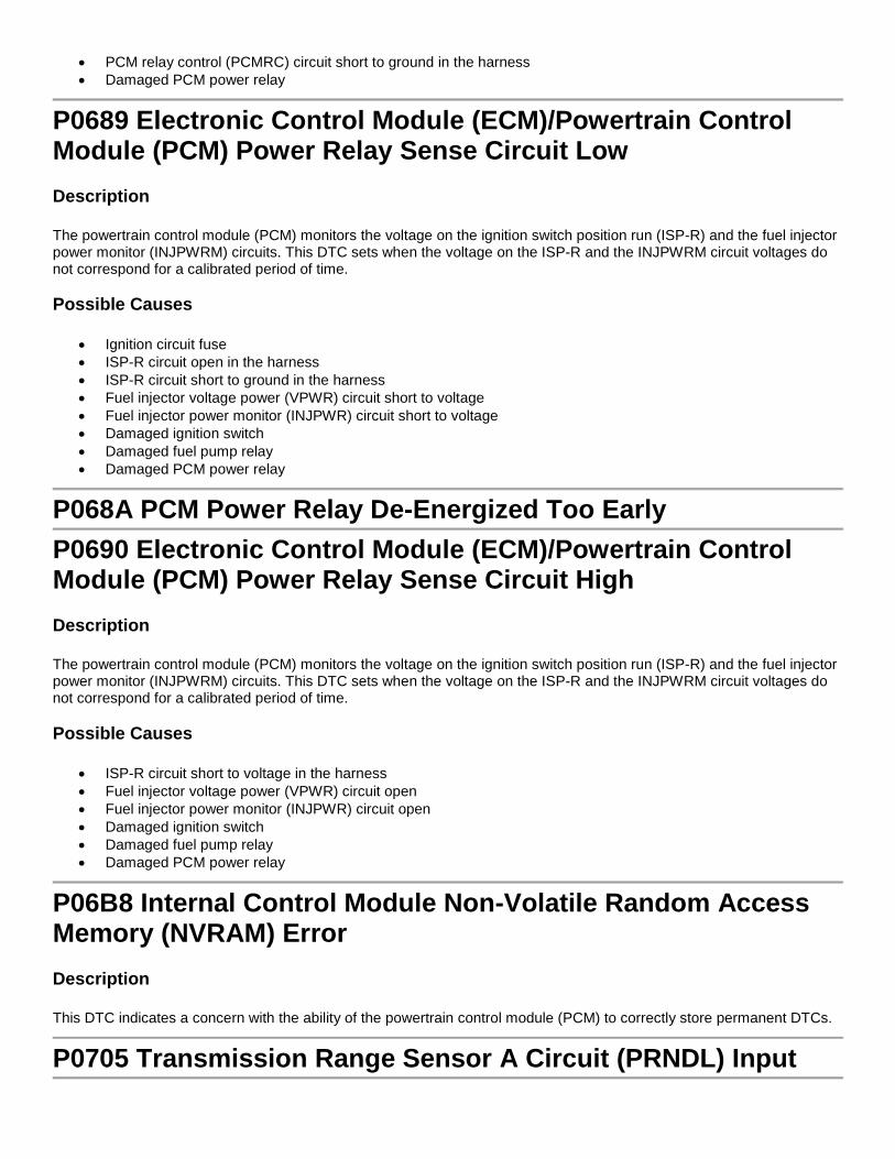
• PCM relay control (PCMRC) circuit short to ground in the harness • Damaged PCM power relay
P0689 Electronic Control Module (ECM)/Powertrain Control Module (PCM) Power Relay Sense Circuit Low Description
The powertrain control module (PCM) monitors the voltage on the ignition switch position run (ISP-R) and the fuel injector power monitor (INJPWRM) circuits. This DTC sets when the voltage on the ISP-R and the INJPWRM circuit voltages do not correspond for a calibrated period of time. Possible Causes
• Ignition circuit fuse • ISP-R circuit open in the harness • ISP-R circuit short to ground in the harness • Fuel injector voltage power (VPWR) circuit short to voltage • Fuel injector power monitor (INJPWR) circuit short to voltage • Damaged ignition switch • Damaged fuel pump relay • Damaged PCM power relay
P068A PCM Power Relay De-Energized Too EarlyP0690 Electronic Control Module (ECM)/Powertrain Control Module (PCM) Power Relay Sense Circuit High Description
The powertrain control module (PCM) monitors the voltage on the ignition switch position run (ISP-R) and the fuel injector power monitor (INJPWRM) circuits. This DTC sets when the voltage on the ISP-R and the INJPWRM circuit voltages do not correspond for a calibrated period of time. Possible Causes
• ISP-R circuit short to voltage in the harness • Fuel injector voltage power (VPWR) circuit open • Fuel injector power monitor (INJPWR) circuit open • Damaged ignition switch • Damaged fuel pump relay • Damaged PCM power relay
P06B8 Internal Control Module Non-Volatile Random Access Memory (NVRAM) Error Description
This DTC indicates a concern with the ability of the powertrain control module (PCM) to correctly store permanent DTCs.
P0705 Transmission Range Sensor A Circuit (PRNDL) Input
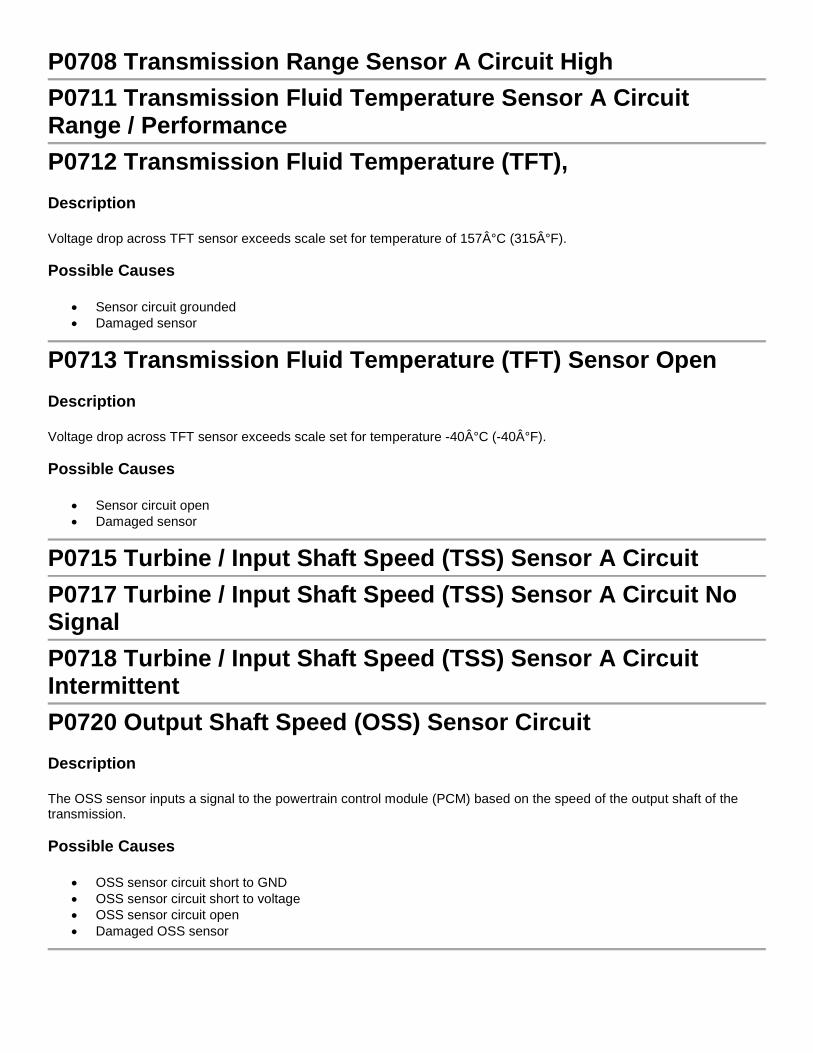
P0708 Transmission Range Sensor A Circuit HighP0711 Transmission Fluid Temperature Sensor A Circuit Range / PerformanceP0712 Transmission Fluid Temperature (TFT), Description
Voltage drop across TFT sensor exceeds scale set for temperature of 157°C (315°F). Possible Causes
• Sensor circuit grounded • Damaged sensor
P0713 Transmission Fluid Temperature (TFT) Sensor Open Description
Voltage drop across TFT sensor exceeds scale set for temperature -40°C (-40°F). Possible Causes
• Sensor circuit open • Damaged sensor
P0715 Turbine / Input Shaft Speed (TSS) Sensor A CircuitP0717 Turbine / Input Shaft Speed (TSS) Sensor A Circuit No SignalP0718 Turbine / Input Shaft Speed (TSS) Sensor A Circuit IntermittentP0720 Output Shaft Speed (OSS) Sensor Circuit Description
The OSS sensor inputs a signal to the powertrain control module (PCM) based on the speed of the output shaft of the transmission. Possible Causes
• OSS sensor circuit short to GND • OSS sensor circuit short to voltage • OSS sensor circuit open • Damaged OSS sensor

P0721 Output Shaft Speed (OSS) Sensor Circuit Range/Performance Description
The OSS sensor signal is very sensitive to noise. This noise distorts the input to the powertrain control module (PCM). Possible Causes
• Wiring misrouted • Aftermarket add-on • Wiring damaged • Wiring insulation wear
P0722 Output Shaft Speed (OSS) Sensor Circuit No Signal Description
The OSS sensor failed to provide a signal to the powertrain control module (PCM) upon initial movement of vehicle. Possible Causes
• Damaged OSS connector • Damaged OSS sensor, or not installed correctly • Harness intermittently short or open
P0731 Gear 1 (1GR) Incorrect RatioP0732 Gear 2 (2GR) Incorrect Ratio
P0740 Torque Converter Clutch (TCC) Solenoid Circuit / OpenP0741 Torque Converter Clutch (TCC) Solenoid Circuit Perf. Or Stuck OffP0743 Torque Converter Clutch (TCC) Solenoid Circuit Electrical
P0748 Pressure Control Solenoid A (PC-A) ElectricalP0750 Shift Solenoid A (SS-A)P0753 Shift Solenoid A (SS-A) ElectricalP0755 Shift Solenoid B (SS-B)P0758 Shift Solenoid B (SS-B) ElectricalP0960 Pressure Control Solenoid A (PC-A) Control Circuit / Open

P0962 Pressure Control Solenoid A (PC-A) Control Circuit LowP0963 Pressure Control Solenoid A (PC-A) Control Circuit HighP1000 On-Board Diagnostic (OBD) Systems Readiness Test Not Complete Description
The OBD monitors are carried out during the OBD drive cycle. This DTC is stored in continuous memory if any of the OBD monitors do not carry out their full diagnostic check. Possible Causes
• The vehicle is new from the factory • Battery or powertrain control module (PCM) had recently been disconnected • An OBD monitor concern occurred before completion of an OBD drive cycle • PCM DTCs have recently been cleared with a scan tool • Power take-off (PTO) circuit concern or PTO is on during testing
P1001 Key On Engine Running (KOER) Not Able To Complete, KOER Aborted This non-malfunction indicator lamp (MIL) DTC sets when the KOER self-test does not complete in the time allowed. Possible Causes
• Incorrect self-test procedure • Unexpected response from the self-test monitors • RPM out of specification
P1101 Mass Air Flow (MAF) Sensor Out of Self-Test Range Description
The MAF sensor circuit is monitored by the powertrain control module (PCM) for an out of range air flow (or voltage) input. If, during ignition on engine off, the air flow voltage signal is greater than 0.27 volt the test fails. Likewise, if, during ignition on engine running, the air flow voltage signal is not within 0.46 volt to 2.44 volts, the test fails. Possible Causes
• Low battery charge • MAF sensor partially connected • MAF sensor contamination • PWR GND open to the MAF sensor • MAF RTN circuit open to PCM • Damaged MAF sensor
P1124 Throttle Position Sensor A Out Of Self-Test Range Description

During key on engine off (KOEO) and key on engine running (KOER) self-tests, the powertrain control module (PCM) monitors the electronic throttle control (ETC) throttle position (TP) sensor inputs to determine if the TP1 and TP2 signals are less than an expected value. If either TP1 or TP2 is greater than the expected value, the DTC is set. Possible Causes
• Accelerator pedal applied during KOEO or KOER self-test
P1127 Exhaust Temperature Out of Range, O2 Sensor Tests Not Completed Description
The heated oxygen sensor (HO2S) monitor uses an exhaust temperature model to determine when the HO2S heaters are cycled ON. The test fails when the inferred exhaust temperature is below a minimum calibrated value. Possible Causes
• Engine not operating long enough prior to carrying out the key on engine running (KOER) self-test • Exhaust system too cool
P115E Throttle Actuator Control (TAC) Throttle Body Air Flow Trim at Max Limit Description
During idle, the powertrain control module (PCM) monitors the throttle angle and air flow. If the air flow is determined to be less than expected, the PCM adjusts the throttle angle to compensate. The air flow reduction is typically the result of engine deposit buildup around the throttle plate. This DTC indicates the PCM has reached the maximum allowed compensation and is no longer able to compensate for the buildup. Possible Causes
• Engine deposits around the throttle plate
P1260 Theft Detected, Vehicle Immobilized Description
This DTC can be set if the passive anti-theft system (PATS) has determined a theft condition existed and the engine is disabled or an engine start was attempted using a non-PATS key. This DTC is a good indicator to check the PATS for DTCs. This DTC can also be set when a new instrument cluster (IC) or powertrain control module (PCM) is installed without correctly programming either module even if the vehicle is not equipped with PATS. Possible Causes
• Incorrectly programmed PCM • Incorrectly programmed IC or IPC • Previous theft condition • Anti-theft system concern

P1285 Cylinder Head Over Temperature Condition Description
Indicates an engine overheat condition was sensed by the cylinder head temperature (CHT) sensor. Possible Causes
• Low engine coolant level • Base engine concerns • Engine cooling system concerns • CHT sensor concern
P1288 Cylinder Head Temperature (CHT) Sensor Out of Self-Test Range Description
Indicates the CHT sensor is out of self-test range. The engine is not at a normal operating temperature. Possible Causes
• Cold engine • Engine overheating • Damaged harness connector • Low engine coolant level • Damaged CHT sensor
P1289 Cylinder Head Temperature (CHT) Sensor Circuit High Description
This indicates a CHT sensor circuit open. Possible Causes
• Open CHT sensor circuit • CHT sensor circuit short to voltage • Damaged CHT sensor • Incorrect harness connection
P128A Cylinder Head Temperature (CHT) Sensor Circuit Intermittent/Erratic Description
Indicates the CHT circuit became intermittently open or short while the engine was running. Possible Causes
• Damaged harness or connector • Damaged sensor

• Open or short in the CHT circuit
P1290 Cylinder Head Temperature (CHT) Sensor Circuit Low Description
This indicates a CHT sensor circuit short to ground. Possible Causes
• Grounded circuit in CHT harness • Damaged CHT sensor • Incorrect harness connection
P1299 Cylinder Head Over Temperature Protection Active Description
Indicates an engine overheat condition was detected by the cylinder head temperature (CHT) sensor. A failure mode effects management (FMEM) strategy called fail-safe cooling was activated to cool the engine. Possible Causes
• Engine cooling system concerns • Low engine coolant level • Base engine concerns
P1336 Crankshaft/Camshaft Sensor Range/Performance Description
The input signal to the powertrain control module (PCM) from the crankshaft position (CKP) sensor or the camshaft position (CMP) sensor is erratic. Possible Causes
• Damaged CKP sensor • Damaged CMP sensor • Base engine concerns • Harness concerns
P1397 System Voltage Out Of Self -Test Range Description
This DTC indicates that the 12-volt system voltage is too high or too low during the key on engine off (KOEO) or key on engine running (KOER) self-test. It sets if the system voltage falls below or exceeds the calibrated threshold at any time during the KOEO or KOER self-test. Possible Causes
• Battery or charging system concern

P1408 Exhaust Gas Recirculation (EGR) Flow Out Of Self-Test Range Description
This test is carried out during the key on engine running (KOER) on demand self-test only. The EGR system is commanded on at a fixed engine speed. The test does not pass and the DTC is set when the measured EGR flow falls above or below the required calibration. Possible Causes
• For electric EGR (EEGR) system, see possible causes for DTC P0400. • For vacuum activated systems, see the possible causes for DTC P0401.
P144A Evaporative Emission System Purge Vapor Line Restricted/Blocked Description
The powertrain control module (PCM) monitors the evaporative emission (EVAP) system for a blocked fuel vapor tube between the fuel tank pressure (FTP) sensor and the fuel tank. During the initial phase of the EVAP monitor, the PCM closes the canister vent and a vacuum develops in the fuel vapor tubes and lines and in the fuel tank. The PCM monitors the FTP sensor to determine the amount of vacuum and how quickly the vacuum increases. The rate at which the vacuum increases is compared to an expected value. If the vacuum increases quicker than expected, a blocked fuel vapor tube is suspected and an intrusive test is carried out in the final phase of the EVAP monitor. If the intrusive test confirms a blockage a counter is incremented and once the counter reaches a calibrated number of completions, the DTC is set. Possible Causes
• Blocked fuel vapor tube between the FTP sensor and the fuel tank
P1450 Unable to Bleed Up Fuel Tank Vacuum Description
This monitors the fuel vapor vacuum and pressure in the fuel tank. System failure occurs when the evaporative emission (EVAP) running loss monitor detects excessive fuel tank vacuum with the engine running, but not at idle. Possible Causes
• Blockages or kinks in the EVAP canister tube or EVAP canister purge outlet tube between the fuel tank, the EVAP canister purge valve and the EVAP canister
• Fuel filler cap stuck closed, preventing vacuum relief • Capless fuel tank filler pipe damaged, preventing vacuum relief (if equipped) • Contaminated fuel vapor elbow on the EVAP canister • Restricted EVAP canister • Canister vent (CV) solenoid stuck partially or fully open • Plugged CV solenoid filter • EVAP canister purge valve stuck open • VREF circuit open in the harness near the fuel tank pressure (FTP) sensor, the FTP sensor or the powertrain
control module (PCM)

• Damaged FTP sensor
P1464 A/C Demand (ACD) Out of Self-Test RangeP1500 Vehicle Speed Sensor (VSS) Description
Indicates the VSS input signal was intermittent. This DTC sets when a VSS concern interferes with other on board diagnostics (OBD) tests, such as the catalyst efficiency monitor, the evaporative emission EVAP monitor or the heated oxygen sensor HO2S monitor. Possible Causes
• Intermittent VSS connections • Intermittent open in the VSS harness circuit(s) • Intermittent short in VSS harness circuit(s) • Damaged VSS
P1501 Vehicle Speed Sensor (VSS) Out of Self-Test Range Description
Indicates the VSS input signal is out of self-test range. If the powertrain control module (PCM) detects a VSS input signal any time during the self-test, DTC P1501 is set and the test aborts. Possible Causes
• Noise on the VSS input signal from the radio frequency interference or electromagnetic interference • External sources, such as ignition wires, the charging circuit or aftermarket equipment
P1502 Vehicle Speed Sensor (VSS) Intermittent Description
Indicates the powertrain control module (PCM) detected an error in the vehicle speed information. Vehicle speed data is received from either the VSS, transfer case speed sensor (TCSS) or anti-lock brake system (ABS) control module. This DTC sets the same way as P0500. However, it is intended to flash the transmission control indicator lamp (TCIL) for first time VSS circuit error. Possible Causes
• Noisy VSS input signal from the radio frequency interference / electromagnetic interference (RFI/EMI) external sources, such as ignition wires, the charging circuit or after market equipment
P1534 Restraint Deployment Indicator CircuitP1575 Pedal Position Out Of Self Test Range Description
During key on engine off (KOEO) self-test, the powertrain control module (PCM) monitors the accelerator pedal position (APP) sensor inputs to determine if the APP1 and APP2 signals are less than an expected value. If either APP1 or APP2 is greater than the expected value, the DTC is set.
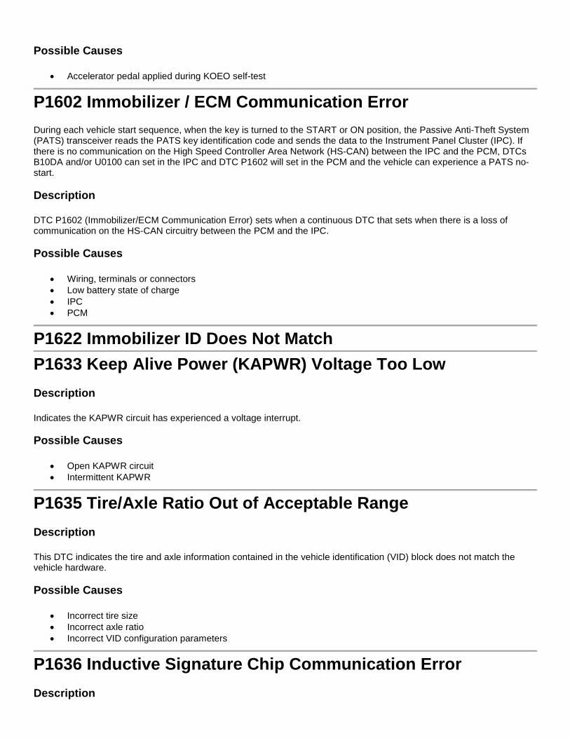
Possible Causes
• Accelerator pedal applied during KOEO self-test
P1602 Immobilizer / ECM Communication Error During each vehicle start sequence, when the key is turned to the START or ON position, the Passive Anti-Theft System (PATS) transceiver reads the PATS key identification code and sends the data to the Instrument Panel Cluster (IPC). If there is no communication on the High Speed Controller Area Network (HS-CAN) between the IPC and the PCM, DTCs B10DA and/or U0100 can set in the IPC and DTC P1602 will set in the PCM and the vehicle can experience a PATS no-start. Description
DTC P1602 (Immobilizer/ECM Communication Error) sets when a continuous DTC that sets when there is a loss of communication on the HS-CAN circuitry between the PCM and the IPC. Possible Causes
• Wiring, terminals or connectors • Low battery state of charge • IPC • PCM
P1622 Immobilizer ID Does Not Match
P1633 Keep Alive Power (KAPWR) Voltage Too Low Description
Indicates the KAPWR circuit has experienced a voltage interrupt. Possible Causes
• Open KAPWR circuit • Intermittent KAPWR
P1635 Tire/Axle Ratio Out of Acceptable Range Description
This DTC indicates the tire and axle information contained in the vehicle identification (VID) block does not match the vehicle hardware. Possible Causes
• Incorrect tire size • Incorrect axle ratio • Incorrect VID configuration parameters
P1636 Inductive Signature Chip Communication Error Description
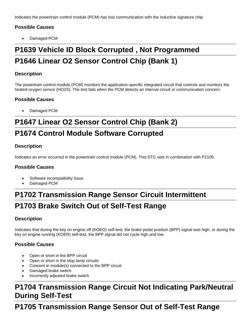
Indicates the powertrain control module (PCM) has lost communication with the inductive signature chip. Possible Causes
• Damaged PCM
P1639 Vehicle ID Block Corrupted , Not Programmed
P1646 Linear O2 Sensor Control Chip (Bank 1) Description
The powertrain control module (PCM) monitors the application-specific integrated circuit that controls and monitors the heated oxygen sensor (HO2S). The test fails when the PCM detects an internal circuit or communication concern. Possible Causes
• Damaged PCM
P1647 Linear O2 Sensor Control Chip (Bank 2)P1674 Control Module Software Corrupted Description
Indicates an error occurred in the powertrain control module (PCM). This DTC sets in combination with P2105. Possible Causes
• Software incompatibility issue • Damaged PCM
P1702 Transmission Range Sensor Circuit IntermittentP1703 Brake Switch Out of Self-Test Range Description
Indicates that during the key on engine off (KOEO) self-test, the brake pedal position (BPP) signal was high, or during the key on engine running (KOER) self-test, the BPP signal did not cycle high and low. Possible Causes
• Open or short in the BPP circuit • Open or short in the stop lamp circuits • Concern in module(s) connected to the BPP circuit • Damaged brake switch • Incorrectly adjusted brake switch
P1704 Transmission Range Circuit Not Indicating Park/Neutral During Self-TestP1705 Transmission Range Sensor Out of Self-Test Range

P1711 Transmission Fluid Temperature (TFT) Sensor Out of Self-Test RangeP1714 Shift Solenoid A Inductive SignatureP1715 Shift Solenoid B Inductive Signature
P1740 Torque Converter Clutch (TCC) Solenoid Inductive SignatureP1742 Torque Converter Clutch (TCC) Solenoid Circuit Failed OnP1743 Torque Converter Clutch (TCC) Solenoid Circuit Failed On
P1744 Torque Converter Clutch (TCC) Solenoid Circuit PerformanceP174E Output Shaft Speed / ABS Wheel Speed CorrelationP1780 Transmission Control Switch (TCS) Out of Self-Test Range Description
During key on engine running (KOER) self-test the TCS must be cycled, or a DTC is set. Possible Causes
• TCS not cycled during the self-test • TCS circuit short or open • Damaged TCS switch
P1781 4x4L Switch Out of Self-Test Range Description
The 4x4L switch is an on/off switch. If the powertrain control module (PCM) does not sense low voltage when the switch is on, the DTC sets. Possible Causes
• Open or short in the 4x4L harness • Damaged electronic shift module
P1783 Transmission Over Temperature ConditionP1921 Transmission Range Signal

P2096 Post Catalyst Fuel Trim System Too Lean Bank 1 Description
The powertrain control module (PCM) monitors the correction value from downstream heated oxygen sensor (HO2S) as part of the fore-aft oxygen sensor control routine. The test fails when the correction value is greater than a calibrated limit. Possible Causes
• Corrosion • Incorrect connections • Exhaust leaks • Contaminated HO2S
P2097 Post Catalyst Fuel Trim System Too Rich Bank 1 Description
The powertrain control module (PCM) monitors the correction value from downstream heated oxygen sensor (HO2S) as part of the fore-aft oxygen sensor control routine. The test fails when the correction value is greater than a calibrated limit. Possible Causes
• Corrosion • Incorrect connections • Exhaust leaks • Contaminated HO2S
P2098 Post Catalyst Fuel Trim System Too Lean Bank 2 Description
The powertrain control module (PCM) monitors the correction value from downstream heated oxygen sensor (HO2S) as part of the fore-aft oxygen sensor control routine. The test fails when the correction value is greater than a calibrated limit. Possible Causes
• Corrosion • Incorrect connections • Exhaust leaks • Contaminated HO2S
P2099 Post Catalyst Fuel Trim System Too Rich Bank 2 Description
The powertrain control module (PCM) monitors the correction value from downstream heated oxygen sensor (HO2S) as part of the fore-aft oxygen sensor control routine. The test fails when the correction value is greater than a calibrated limit. Possible Causes
• Corrosion • Incorrect connections

• Exhaust leaks • Contaminated HO2S
P2101 Throttle Actuator Control (TAC) Motor Range/Performance Description
A powertrain control module (PCM) fault flag is set indicating the motor circuit is open, and may require cycling the ignition. Possible Causes
• TAC motor circuits are cross-wired
P2107 Throttle Actuator Control (TAC) Module Processor Description
The electronic throttle control (ETC) area of the powertrain control module (PCM) failed the self-test. The concern could be the result of an incorrect throttle position (TP) command, or TAC motor wires shorted together. Possible Causes
• TAC motor harness circuit short to ground • TAC motor harness circuit short to voltage • Damaged electronic throttle body (ETB) • Damaged PCM
P2111 Throttle Actuator Control (TAC) System - Stuck Open Description
This powertrain control module (PCM) fault status indicates the throttle plate is at a greater angle than commanded. Possible Causes
• Binding throttle body, stuck open • TAC motor circuit open • TAC motor circuits are cross-wired • TAC motor harness circuits are shorted together • Damaged PCM
P2112 Throttle Actuator Control (TAC) System - Stuck Closed Description
This powertrain control module (PCM) fault status indicates the throttle plate is at a lower angle than commanded. Possible Causes
• Binding throttle body, stuck closed • TAC motor circuit open TAC motor circuits are cross-wired

• TAC motor harness circuits are shorted together • Damaged PCM
P2122 Throttle/Pedal Position Sensor/Switch D Circuit Low Description
The accelerator pedal position (APP) sensor 1 is out of self-test range low. Possible Causes
• APP sensor harness open (ETC system with a 2-track APP sensor) • APP sensor harness short to ground • Damaged APP sensor
P2123 Throttle/Pedal Position Sensor/Switch D Circuit High Description
The accelerator pedal position (APP) sensor 1 is out of self-test range high. Possible Causes
• APP sensor harness open (ETC system with a 3-track APP sensor) • APP sensor harness short to voltage • Damaged APP sensor
P2127 Throttle/Pedal Position Sensor/Switch E Circuit Low Description
The accelerator pedal position (APP) sensor 2 is out of self-test range low. Possible Causes
• APP sensor circuit is short to ground • APP sensor circuit is open • Damaged APP sensor
P2128 Throttle/Pedal Position Sensor/Switch E Circuit High Description
The accelerator pedal position (APP) sensor 2 is out of self-test range high. Possible Causes
• APP sensor assembly is binding • APP sensor harness short to voltage • Damaged APP sensor
P2135 Throttle/Pedal Position Sensor/Switch A/B Voltage Correlation Description
The powertrain control module (PCM) flagged a concern indicating that throttle position voltage PIDs TP1 and TP2 disagree by more than a calibrated limit. Possible Causes
• Corrosion or incorrect connection at the ETC TP sensor terminals and wiring • Damaged TP sensor
P2138 Throttle/Pedal Position Sensor/Switch D/E Voltage Correlation Description
The powertrain control module (PCM) monitors the accelerator pedal position (APP) sensor for a concern. The PCM compares the accelerator pedal position information from the APP sensor inputs, APP1 and APP2. If the APP sensor inputs APP1 and APP2 disagree on the position of the accelerator pedal by more than an expected value, the DTC is set. Possible Causes
• APP sensor circuit concerns • Damaged APP sensor
P2195 O2 Sensor Signal Biased/Stuck Lean - Bank 1, Sensor 1 Description
A heated oxygen sensor (HO2S) indicating lean at the end of a test is trying to correct for an over-rich condition. The test fails when the fuel control system no longer detects switching for a calibrated amount of time. Possible Causes
• Electrical: o Short to voltage in the harness or HO2S o Water in the harness connector o Open HO2S circuit o Open UO2SPC circuit o Corrosion Incorrect connections o Damaged HO2S o Damaged powertrain control module (PCM)
• Fuel System: o Excessive fuel pressure o Leaking or contaminated fuel injectors o Leaking fuel pressure regulator o Low fuel pressure or running out of fuel o Vapor recovery system
• Intake Air System: o Air leaks after the mass air flow (MAF) sensor o Vacuum leaks o Positive crankcase ventilation (PCV) system is leaking or the valve is stuck open o Incorrectly seated engine oil dipstick

• Exhaust Gas Recirculation (EGR) System: o Leaking gasket o Stuck EGR valve o Leaking diaphragm or EGR vacuum regulator
• Base Engine: o Oil overfill o Camshaft timing o Cylinder compression o Exhaust leaks before or near the HO2S
P2196 O2 Sensor Signal Biased/Stuck Rich - Bank 1, Sensor 1 Description
A heated oxygen sensor (HO2S) indicating rich at the end of a test is trying to correct for an over-lean condition. The test fails when the fuel control system no longer detects switching for a calibrated amount of time. Possible Causes
• Electrical: o Short to voltage in the harness or HO2S o Water in the harness connector o Open HO2S circuit o Open UO2SPC circuit o Corrosion o Incorrect connections o Damaged HO2S Damaged powertrain control module (PCM)
• Fuel System: o Excessive fuel pressure o Leaking or contaminated fuel injectors o Leaking fuel pressure regulator o Low fuel pressure or running out of fuel o Vapor recovery system
• Intake Air System: o Air leaks after the mass air flow (MAF) sensor o Vacuum Leaks o Positive crankcase ventilation (PCV) system Incorrectly seated engine oil dipstick
• EGR System: o Leaking gasket o Stuck EGR valve o Leaking diaphragm or EGR vacuum regulator
• Base Engine: o Oil overfill o Cam Timing o Cylinder compression o Exhaust leaks before or near the HO2S(s)
P2197 O2 Sensor Signal Biased/Stuck Lean - Bank 2, Sensor 1 Description
A heated oxygen sensor (HO2S) indicating lean at the end of a test is trying to correct for an over-rich condition. The test fails when the fuel control system no longer detects switching for a calibrated amount of time. Possible Causes
• Electrical: o Short to voltage in the harness or HO2S

o Water in the harness connector o Open HO2S circuit o Open UO2SPC circuit o Corrosion o Incorrect connections o Damaged HO2S Damaged powertrain control module (PCM)
• Fuel System: o Excessive fuel pressure o Leaking or contaminated fuel injectors o Leaking fuel pressure regulator o Low fuel pressure or running out of fuel o Vapor recovery system
• Intake Air System: o Air leaks after the mass air flow (MAF) sensor o Vacuum Leaks o Positive crankcase ventilation (PCV) system Incorrectly seated engine oil dipstick
• EGR System: o Leaking gasket o Stuck EGR valve o Leaking diaphragm or EGR vacuum regulator
• Base Engine: o Oil overfill o Cam Timing o Cylinder compression o Exhaust leaks before or near the HO2S(s)
P2198 O2 Sensor Signal Biased/Stuck Rich - Bank 2, Sensor 1 Description
A heated oxygen sensor (HO2S) indicating rich at the end of a test is trying to correct for an over-lean condition. The test fails when the fuel control system no longer detects switching for a calibrated amount of time. Possible Causes
• Electrical: o Short to voltage in the harness or HO2S o Water in the harness connector o Open HO2S circuit o Open UO2SPC circuit o Corrosion o Incorrect connections o Damaged HO2S Damaged powertrain control module (PCM)
• Fuel System: o Excessive fuel pressure o Leaking or contaminated fuel injectors o Leaking fuel pressure regulator o Low fuel pressure or running out of fuel o Vapor recovery system
• Intake Air System: o Air leaks after the mass air flow (MAF) sensor o Vacuum Leaks o Positive crankcase ventilation (PCV) system Incorrectly seated engine oil dipstick
• EGR System: o Leaking gasket o Stuck EGR valve o Leaking diaphragm or EGR vacuum regulator
• Base Engine: o Oil overfill o Cam Timing

o Cylinder compression o Exhaust leaks before or near the HO2S(s)
P2270 O2 Sensor Signal Biased / Stuck Lean (bank 1 sensor 2)P2271 O2 Sensor Signal Stuck Rich - Bank 1, Sensor 2 Description
The downstream heated oxygen sensor (HO2S) is forced rich and lean and monitored by the powertrain control module (PCM). The test fails if the PCM does not detect the output of the HO2S in a calibrated amount of time. Possible Causes
• Pinched, shorted, and corroded wiring and pins • Crossed HO2S wires • Exhaust leaks • Contaminated or damaged HO2S
P2272 O2 Sensor Signal Stuck Lean - Bank 2, Sensor 2 Description
The downstream heated oxygen sensor (HO2S) is forced rich and lean and monitored by the powertrain control module (PCM). The test fails if the PCM does not detect the output of the HO2S in a calibrated amount of time. Possible Causes
• Pinched, shorted, and corroded wiring and pins • Crossed HO2S wires • Exhaust leaks • Contaminated or damaged HO2S
P2273 O2 Sensor Signal Stuck Rich - Bank 2, Sensor 2 Description
The downstream heated oxygen sensor (HO2S) is forced rich and lean and monitored by the powertrain control module (PCM). The test fails if the PCM does not detect the output of the HO2S in a calibrated amount of time. Possible Causes
• Pinched, shorted, and corroded wiring and pins • Crossed HO2S wires • Exhaust leaks • Contaminated or damaged HO2S
P260F Evaporative System Monitoring Processor Performance Description
This DTC sets when a concern is detected internal to the powertrain control module (PCM). The microprocessor that controls the engine off natural vacuum (EONV) leak check monitor is separate from the main processor within the PCM.

Possible Causes
• Module communications network concerns • PCM calibration level • Damaged PCM
P2610 Electronic Control Module (ECM)/Powertrain Control Module (PCM) Internal Engine Off Timer Performance Description
This indicates an error in the internal PCM engine off timer processor. Possible Causes
• Incorrect or intermittent battery cable connections • Keep alive power (KAPWR) circuit to PCM concern • Engine coolant temperature (ECT) sensor • Engine cooling system concerns • Electrical interference around vehicle or PCM
U0002 High Speed CAN Communication Bus Performance The IPC could not communicate on the HS-CAN at a point in time. The fault is currently not present since the IPC is currently communicating on the HS-CAN to report this DTC. CLEAR the DTC. REPEAT the network test with the scan tool.
U0011 Medium Speed CAN Communication Bus Performance The IPC could not communicate on the MS-CAN at a point in time. The IPC communicates with the scan tool on the HS-CAN. CLEAR the DTC. REPEAT the network test with the scan tool.
U0073 FL_BUS_OFF The ABS module could not communicate on the network at a point in time. The fault is currently not present since the ABS module is currently communicating on the HS-CAN to report this DTC. CLEAR the DTC. REPEAT the network test with the scan tool.
U0100 Lost Communication With ECM/PCM "A" During each vehicle start sequence, when the key is turned to the START or ON position, the Passive Anti-Theft System (PATS) transceiver reads the PATS key identification code and sends the data to the Instrument Panel Cluster (IPC). If there is no communication on the High Speed Controller Area Network (HS-CAN) between the IPC and the PCM, DTCs B10DA and/or U0100 can set in the IPC and DTC P1602 will set in the PCM and the vehicle can experience a PATS no-start. Description
DTC U0100 (Lost Communication With ECM/PCM "A": No Sub Type Information) — a continuous DTC that sets only when the IPC loses communication with the PCM and the fault may not be present at the time of testing. This DTC can be caused by an HS-CAN circuit concern or the IPC or PCM. Possible Causes

• Wiring • Terminals or connectors • Low battery state of charge • IPC • PCM
U0101 Lost Communication with TCMU0121 Lost Communication With Fuel Pump Control Module Description
The powertrain control module (PCM) continuously monitors the controller area network (CAN) for messages from the ABS. This DTC sets when the PCM fails to receive the ABS message within the defined amount of time.
U0140 Lost Communication With Body Control ModuleU0151 Lost Communication With Restraints Control Module
U0155 Lost Communication With Instrument Panel Cluster (IPC) Control ModuleU0300 Internal Control Module Software Incompatibility Description
This DTC indicates there are incompatible software levels within the powertrain control module (PCM) that control the electronic throttle control (ETC) system. The ETC system uses multiple microprocessors within the PCM, each having its own software level and function. The microprocessors must have the correct level of software in order to communicate and function together.
U0401 Invalid Data Received from ECM/PCM AU0422 Invalid Data Received From Body Control ModuleU0430 Invalid Data Received From Tire Pressure Monitor Module
U2050 No application present
U2100 Initial Configuration Not CompleteU2472 Unexpected Ignition StateU2473 Unexpected Vehicle SpeedU3000 Control ModuleU3003 Battery Voltage