THE VBOW AN EXPRESSIVE MUSICAL …cnichols/pdf/vBow...vi cited from texts, describing the affect of...
165
THE VBOW AN EXPRESSIVE MUSICAL CONTROLLER HAPTIC HUMAN-COMPUTER INTERFACE A DISSERTATION SUBMITTED TO THE DEPARTMENT OF MUSIC AND THE COMMITTEE OF GRADUATE STUDIES OF STANFORD UNIVERSITY IN PARTIAL FULFILLMENT OF THE REQUIREMENTS FOR THE DEGREE OF DOCTOR OF PHILOSOPHY Charles Sabin Nichols II August 2003
Transcript of THE VBOW AN EXPRESSIVE MUSICAL …cnichols/pdf/vBow...vi cited from texts, describing the affect of...
THE VBOWAN EXPRESSIVE MUSICAL CONTROLLERHAPTIC HUMAN-COMPUTER INTERFACE
A DISSERTATION
SUBMITTED TO THE DEPARTMENT OF MUSIC
AND THE COMMITTEE OF GRADUATE STUDIES
OF STANFORD UNIVERSITY
IN PARTIAL FULFILLMENT OF THE REQUIREMENTS
FOR THE DEGREE OF
DOCTOR OF PHILOSOPHY
Charles Sabin Nichols II
August 2003
ii
© Copyright by Charles Sabin Nichols IIAll Rights Reserved

iii
I certify that I have read this dissertation and that, in my opinion, it is fully adequatein scope and quality as a dissertation for the degree of Doctor of Philosophy.
______________________________Chris Chafe, Principal Adviser
I certify that I have read this dissertation and that, in my opinion, it is fully adequatein scope and quality as a dissertation for the degree of Doctor of Philosophy.
______________________________Jonathan Berger
I certify that I have read this dissertation and that, in my opinion, it is fully adequatein scope and quality as a dissertation for the degree of Doctor of Philosophy.
______________________________Max Mathews
I certify that I have read this dissertation and that, in my opinion, it is fully adequatein scope and quality as a dissertation for the degree of Doctor of Philosophy.
______________________________Julius O. Smith III
Approved for the University Committee on Graduate Studies:
______________________________
iv
ABSTRACT
This dissertation describes the development of the vBow, a virtual violin bow controller.
This interface was designed to accurately sense the component physical motions of a
violinist’s bowing gesture, while providing the performer with both the auditory feedback of
the sound synthesis and the tactile sensations of the haptic feedback, produced by the
system. Both the sound synthesis and haptic feedback are generated by software which
uses the sensor readings, from the encoders on the vBow, as parameter data for a bowed
string physical model, a friction model, and simulations of detents, elasticity, and barriers,
produced by the motors on the vBow.
The vBow was designed around the component physical motions of the bowing gesture,
with each encoder sensing the movement, and each servomotor producing the tactile
feedback, that corresponds to the four main trajectories, or degrees of freedom, of the
bowing gesture. On an acoustic violin, the manipulation of each of these four main
trajectories of bowing contributes to the expression inflected in the tone of the violin.
Similarly, with the vBow, maneuvering each of the four degrees of freedom generates data
from each of the four encoders, which affect the parameters of the sound synthesis software,
producing expressive variations in the timbre.
Just as the four component physical motions of bowing contribute to variations in the
timbre produced by both an acoustic violin and the vBow, each degree of freedom also
contributes to the tactile feedback of both systems. For an acoustic violin, each trajectory of
motion produces the tactile feedback of vibration, friction, detents, or elasticity. On the
vBow, each encoder is attached to a servomotor, which generates the same haptic feedback
that corresponds to the bowing motion producing the encoder reading.
The encoders and servomotors used by the vBow were selected for their high resolution of
sensing and wide range of force, to maximize the expressive potential of the instrument.
Similarly, the sound synthesis and haptic feedback models were chosen because of their
responsiveness and flexibility.
To elucidate the importance of expressive potential to the design of an instrument, the
introduction chapter of this dissertation outlines the developmental history of the violin and
bow. The evolution of the expressive possibilities of the violin bow is also illustrated
through a survey of the development of bowing technique. This survey further serves to

v
demonstrate that it is the bow that provides the majority of the expressive variety in violin
dynamics and timbre.
Furthermore, to show that the importance of expressive potential also applies to the
development of computer music interfaces, the introduction chapter presents an overview of
writings by computer musicians expounding the importance and difficulty of expressive
interaction with computer music systems. Finally, to clarify the importance of haptic
feedback to the expressive performance of an instrument, the introduction contains a
discussion of research into measuring and simulating the tactile feedback of musical
instruments.
Later, after a discussion of the motivation behind the project, in order to put the development
of the vBow in a historical perspective, the background chapter of this dissertation contains
an overview of the development of computer music interfaces. This developmental overview
begins with the evolution of early systems, moves through the design of non-keyboard
controllers, focusing primarily on violin and bow interfaces, and concludes with the
production of haptic interfaces, specifically designed for computer music performance and
research. At the heart of the development of these interfaces is the pursuit of an expressive
gestural connection to the powerful and flexible sound synthesis possibilities of the
computer.
Next comes a chapter that steps through the development of the vBow hardware, followed
by a chapter discussing the design and implementation of the software for the vBow system.
Within this chapter about the vBow software, violin tone production is studied, through an
analysis of both treatises by reputed instructors of violin performance from throughout
history, and papers by scientists researching the contribution of bowing parameters to violin
tone production. These two perspectives on the effect of the bow on violin tone production,
the musically practical and scientifically theoretical, are used as a springboard from which
the developmental history of the bowed-string physical model, used in the vBow software, is
discussed.
After this general discussion of the acoustic and electroacoustic production of an expressive
violin timbre, each of the four specific bowing parameters, which correlate to the four kinds
of motion provided by the vBow, are discussed in relation to how they contribute to the
variation of violin timbre, both on an acoustic instrument and in the bowed-string physical
model used by the vBow system software. In support of these discussions, passages are

vi
cited from texts, describing the affect of these four bowing parameters on violin tone
production.
Similarly, each of the four kinds of haptic feedback produced by the vBow system software,
which relate to the component physical motions of a bowing gesture, are discussed in this
chapter. In addition to describing how the haptic effects are generated through the
servomotors on the vBow by the system software, models previously developed by haptics
researchers are discussed.
Finally, in the chapter covering future applications of the vBow, in addition to a general
discussion of possible sound synthesis, haptic feedback, and compositional and
performance applications for the interface, writings by experts on mapping strategies, or
how the output of the interface can be connected to input parameters of the system software,
are presented.

vii
ACKNOWLEDGEMENTS
This research was made possible by the financial support of the Center for Computer
Research in Music and Acoustics, the Department of Music, and the School of Humanities
and Sciences, at Stanford University. Furthermore, this work would not have been possible
without the facilities of Stanford’s Product Realization Lab.
Equipment and supplies for the construction of this project were generously donated by
Advanced Motion Controls, Maxon Precision Motors, the Olander Company, and Sava
Industries.
I would like to thank Chris Chafe for his advice and encouragement throughout the
development of this research and the writing of this dissertation, and for his adroit problem
solving and unwavering focus on musical application. I would also like to thank Kenneth
Salisbury for his initial and continued suggestions, and his keen insight into the
development of a haptic human-computer interface.
I am also grateful to Max Mathews, Julius Smith, and Mark Applebaum for the
recommendations for this research that came from their unique and expert perspectives. I
am especially grateful to Jonathan Berger for his continued support and thoughtful
guidance throughout my musical, academic, and personal exploration.
I am indebted to Stefania Serafin for her development of and assistance with the bowed-
string physical model, Gary Scavone for his programming of and tutorials on the real-time
audio objects in the Synthesis Toolkit, Sile O’Modhrain for her leadership in and advice on
the development of a haptic musical controller, and Vincent Hayward for his development
and explanation of the friction model.
Finally, I would like to thank my parents Roger and Glendy Nichols for their continual
support and encouragement, and my wife Beryl Lee Heuermann and son Solomon Nichols,
to whom this dissertation is dedicated, for their daily care and assistance.

viii
TABLE OF CONTENTS
Title Page ............................................................................................................................. i
Copyright Notice Page ........................................................................................................ ii
Signature Page ................................................................................................................... iii
Abstract .............................................................................................................................. iv
Acknowledgements ........................................................................................................... vii
Table of Contents ............................................................................................................. viii
List of Illustrations .............................................................................................................. x
Chapter 1: Introduction ....................................................................................................... 1History of the Violin ............................................................................................... 1History of the Bow ............................................................................................... 10History of Bowing ................................................................................................ 13Expression in Electroacoustic Music .................................................................... 17Musical Haptics Research ..................................................................................... 29Summary .............................................................................................................. 33
Chapter 2: Motivation ....................................................................................................... 35Composition ......................................................................................................... 35Performance .......................................................................................................... 36Synthesis .............................................................................................................. 38Haptics .................................................................................................................. 39
Chapter 3: Background ..................................................................................................... 41Early Interactive Systems ...................................................................................... 41Non-Keyboard Controllers ................................................................................... 43Violins .................................................................................................................. 47Bows ..................................................................................................................... 55Haptic Interfaces ................................................................................................... 61
Chapter 4: vBow Hardware ............................................................................................... 69Construction ......................................................................................................... 69
Version 1 .................................................................................................. 69Version 2 .................................................................................................. 73Version 2.1 ............................................................................................... 74Version 2.2 ............................................................................................... 80
Electronics ............................................................................................................ 82Version 1 .................................................................................................. 82Version 2 .................................................................................................. 83
Chapter 5: vBow Software ................................................................................................ 86Performance Practice ............................................................................................ 86Bowed-String Physical Model............................................................................... 91
Bowing Parameter Measurement .............................................................. 91Bowed-String Physical Model Development ............................................ 95
Synthesis ............................................................................................................ 108

ix
Velocity ................................................................................................... 108Frequency ............................................................................................... 110Force ....................................................................................................... 110Position ................................................................................................... 113
Haptics ................................................................................................................ 115Vibration ................................................................................................. 116Friction ................................................................................................... 116Detents .................................................................................................... 118Elasticity ................................................................................................. 120
Chapter 6: Application .................................................................................................... 122Overview ............................................................................................................. 122Synthesis ............................................................................................................ 122Haptics ................................................................................................................ 127Composition and Performance ............................................................................ 128
Appendix: Photos ........................................................................................................... 130
Bibliography ................................................................................................................... 133
x
LIST OF ILLUSTRATIONS
1 Max Mathews’ piezoelectric bimorphic pickup bridge on a Zeta electric violin .... 512 Max Mathews’ electronic violin ............................................................................ 513 Ceramic crystal contact microphones on Max Mathews’ electronic violin bridge . 524 Jon Rose with his MIDI bow..................................................................................575 Joseph Paradiso and Neil Gershenfeld’s Hyperviolin .......................................... 596 Diana Young’s Hyperbow .................................................................................... 607 Dan Trueman and Perry Cook’s R-Bow .............................................................. 608 Haptic musical interfaces timeline ......................................................................... 619 Sile O’Modhrain and Brent Gillespie’s Moose .................................................... 6510 Eric Gunther in the Cutaneous Grooves vibrotactile suit ....................................... 6611 Immersion Corporation’s haptic knob used for Lonny Chu’s TouchSound ........ 6712 Construction synopsis .......................................................................................... 6913 The vBow, version 1 .............................................................................................. 6914 Servomotor with encoder and capstan ................................................................... 7015 Acrylic housing with servomotor and linear bearing ............................................. 7116 Fiberglass stick and acrylic frog with eyelet and screw, cable, and ball and shank 7317 The vBow, version 2 .............................................................................................. 7418 The vBow, version 2.1 ........................................................................................... 7519 Degrees of freedom .............................................................................................. 7620 Rotational motion .................................................................................................. 7821 Vertical motion ...................................................................................................... 7922 Longitudinal motion .............................................................................................. 8023 Improved acrylic arm, body, and longitude pieces ................................................. 8124 Electronics for the vBow, version 1 ....................................................................... 8325 Electronics for the vBow, version 2.1 .................................................................... 8526 Bowed-string physical model block diagram ...................................................... 10827 Laser-cutting acrylic pieces ................................................................................. 13028 Acrylic arm and body pieces ............................................................................... 13029 Machining acrylic pieces on a mill ...................................................................... 13130 Acrylic base, longitude, rotation, housing, frog, and tip pieces ............................. 13131 Turning aluminum capstans on a lathe ................................................................ 13232 Aluminum capstans ............................................................................................. 132

1
CHAPTER 1
INTRODUCTION
The vBow is the product of research intent on developing an electronic musical instrument
that expressively translates physical gesture into synthesis parameters, while providing
useful haptic feedback to the performer.
To a composer and performer, expressivity of a musical controller is defined as the ability
of the instrument to map performance gesture to sound synthesis parameters, with fine
resolution in the sensing of physical gesture, and a broad range of response from the
synthesis parameters. The interface is expressive if it amplifies the performance gesture,
translating it into synthesis data that produces a wide range of dynamic and timbral effects.
The development of this correlation between finely resolved physical motion and maximized
dynamic effect is apparent in the evolutionary history of the acoustic bowed-string
instrument, culminating in the modern violin and bow.
History of the Violin
In Hyacinth Abele’s text covering the history of the development of the violin (Abele 1905),
the author begins by describing early bowed-string instruments such as ancient India’s
Ravanastron, a long thin two-stringed instrument made of wood, with boa skin stretched
across for resonance, and gazelle gut for strings, stretched over a bridge, and played with a
bow made from bamboo reed and a horse hair, which he describes as producing a “weak
and dull, though pleasant” tone.
In a poetic account, in his book, The Story of the Violin (Stoeving 1904), Paul Stoeving
writes that Tradition told him that the ancient king Ravana, from the island of Ceylon,
invented this first bowed-string instrument, the Ravanastron, placing the origins of the violin
and bow in Sri Lanka, five thousand years ago.
Stoeving also describes, in detail, the design of the Ravanastron, an instrument on exhibit at
the British Museum:
A small hollow cylinder of sycamore wood, open on one side, on the othercovered with a piece of boa skin (the latter forming the sound-board), istraversed by a long rod of deal – flat on top and rounded underneath – which
2
serves as neck and finger-board, and is slightly bent towards the end wherethe pegs are inserted. Two strings are fastened at the lower end andstretched over a tiny bridge, which rests on the sound-board, and is cutsloping on top. A bow made of bamboo – the hair roughly attached on oneend with a knot, on the other with rush string – completes the outfit.
According to Stoeving’s firsthand account, the tone of the Ravanastron is “soft, thin (a little
muffled, as if muted), ethereal, suggestive, if you will, of thought rather than emotion.”
In his book, The Violin: History, Aesthetics, Manufacture, and Acoustics (Leipp 1969),
Emile Leipp includes an excellent photograph of a Ravanastron, that supports Abele’s and
Stoeving’s descriptions.
Edmond van der Straeten, in his text, The History of the Violin (Van Der Straeten 1968),
begins his chronicle of the development of bowed-string instruments with the Egyptian Lyre
and Kithara, and Persian Rebab, each fostering a branching line of instruments. The author
distinguishes between these lines of instruments according to the shape of their body: the
Lyre, with its rounded back, evolving into the Crwth, the pear-shaped Rebab developing into
the Rebec and Gigue, and the flat Kithara, with its front and back coupled with side-pieces,
prefiguring the modern violin design.
According to van der Straeten’s account, which draws heavily from a genealogical table
illustrated by Kathleen Schlesinger in her book, The Precursors of the Violin Family, the
history of the development of the modern violin design begins with the Egyptian Kithara,
which developed into the Greek Cithara, and later with the Roman Cithara, which was also
called the Fidicula or Rotta. This lineage continues with the Spanish Viguela or Vihuela,
which influenced the French Vielle and Viole, and later the Italian Viola and Violina, which
was a small Viol or Lyra da Braccio.
Abele continues his narrative by describing the ancient Arabic Rebab or Rebek, an oblong
one- to three-stringed instrument, constructed from strips of wood and pieces of parchment,
and used to accompany singing, and the early British Crouth, a bowed three- to six-stringed
trapezoidal instrument with sound-holes cut in the face, and a bridge with one foot that
extends through one of the sound-holes to the back, serving as a soundpost.
Walter Kolneder, in his The Amadeus Book of the Violin: Construction, History, and Music
(Kolneder 1998), explains the function of the soundpost, to the design of the violin. Placed
below the right foot of the bridge, the soundpost impedes the vibrations transmitted from the
3
bridge, while transmitting the vibrations from the top of the body to the back. Although the
importance of this design element is disputed, Kolneder states that “the precise placement
of the soundpost strongly affects volume and especially timbre.” This being the case, the
invention of the soundpost in the early Crouth is a significant contribution to the
developmental history of the bowed-string instrument.
Stoeving also discusses the Rebab, as the first bowed-string instrument in Europe, brought
to Spain by an Arabic invasion, in the eighth century, and prolific throughout Europe in the
Middle Ages. He describes the instrument as “pear-shaped,” with two or three strings, and
two crescent sound-holes.
Van der Straeten adds to our understanding of this kind of bowed-string instrument by
describing the tone of the pear-shaped Rebec as “harsh and dry,” mentioning that it used
to play dance music and “early relegated to fairs and taverns,” although there are records of
it used by court musicians.
Stoeving also discusses the early British instrument, calling it a Crwth, and attributing its
construction to the Welsh. According to his interpretation of a Latin poem composed by
Bishop Venantius Fortunatus, this instrument, which was still performed by Welsh
musicians up to the late eighteenth century, may have predated the introduction of the Rebab
to Europe by as many as two hundred years.
William Sandys, in his text, The History of the Violin (Sandys 1864), also mentions the
early British bowed-string instrument, calling it a bowed Rote or Crwth. Like Abele,
Sandys discusses the three-stringed Crwth, describing the bow used to play the instrument
as “clumsy,” and mentions the six-stringed version, with the bridge that also functions as a
soundpost, providing the same illustration as Abele. In addition to these two versions of the
Crwth, Sandys describes and includes an illustration of a five-string version, that did not
include a neck or bridge, and was played with a short bow, which he likens to a modern bass
bow. He also mentions and presents an illustration of another six-stringed version, with
sound-holes similar in shape and position to the modern violin.
Leipp attributes the invention of this line of bowed-string instruments to the Scandinavians,
who are said to have created the Crouth Trithant, a three-stringed instrument with a
fingerboard. This Crouth of Scandinavian origin is thought to be the ancestor of the Welsh
Crwth, which the author also describes.
4
Adding to what Stoeving and Sandys wrote about the six-string version of the Crwth, Leipp
explains that this instrument had two bass strings, tuned to G2 and G3, that were plucked
with the thumb of the left hand, and four strings, tuned to C4, C3, D3, and D4, that were
bowed. He also clarifies that this early Crwth, which he illustrates with the same drawing as
Abele and Sandys, had a curved bridge, so individual strings could be played separately.
Sandys next presents a four-stringed instrument, with no fingerboard or bridge, but with
low crescent-shaped sound-holes, a wide tailpiece, and a shape generally similar to a modern
violin, with a body that curves in at the sides. This instrument, attributed to Albinus, who
lived until the early ninth century, is pictured with an ornate arched bow. A similar
instrument, with two additional higher crescent sound-holes, is illustrated by the author,
from a carving of the eleventh or twelfth century. This early bowed-string instrument was
placed between the knees of its courtly performer, and played with a bow held underhand.
In his section explaining the dynamics of violin tone production, Kolneder explains the
importance of the placement and shape of the sound-holes (or f-holes) to the volume and
timbre of the tone produced.
The violin’s body, vibrating in its entirety, transmits its vibrations to the air,both inside and outside of the instrument. The outside transmissions aremost important by far for volume and timbre, but the air vibrating inside theviolin, emerging through the f holes, increases volume. The placement of thef holes is of great importance. The shape of the f holes affects thecombination of inside and outside air only slightly but has a far greatereffect on the top’s vibration and hence on tone quality; if they are veryelongated, the top’s middle portion becomes overly elastic in relation to theupper and lower portions, which disturbs the uniformity of sound. Placingthe holes closely together will have the same effect.
Even with these early bowed-string instruments of the Middle Ages, instrument builders
were aware of the importance of this design element, experimenting with the placement and
shape of the sound-holes.
The same carved depiction, described by Sandys, is noted by Stoeving, as an example of a
bowed-string instrument design that differed radically from that of the Rebab. According to
the author, this predecessor to the viol had a shape like a guitar, with “a sonorous chest,
consisting of a back and a belly and sides or ribs connecting them.”

5
These early bowed-string instruments, precursors to the viol, are interesting for the variety
of design choices and experimental engineering they represent, presumably for the sake of
improving their expressive potential.
Sandys places the introduction of the viol in the eighth or ninth century, with the oblong
Lyra (which Stoeving presents in his discussion of the Rebab, pointing out the likeness in
design), a one-stringed viol with a small bridge, and half-circle, centered sound-holes. This
design, which Leipp states was common in the Middle Ages, incorporated a sound post that
fit between the front and back of the body. A three-stringed version of this Lyra, tuned in
fourths, is still used to perform popular Greek music, today.
Sandys presents a wide assortment of viols, with a history of development that continues
until the sixteenth century, describing their shapes, number of strings, pattern and position
of sound-holes, and inclusion or exclusion of a separate neck, fingerboard, bridge, and
tailpiece.
One viol in particular, an Italian Fidel from the beginning of the sixteenth century,
prefigures the design of the modern violin. According to the illustration and description
from van der Straeten, the shape of the body, position of the crescent sound-holes, and
design of the pegbox and pegs are similar in proportion to that of the modern violin.
Abele also continues his discussion of the developmental history of bowed-string
instruments with descriptions of European viols, violins, and fiddles, with various shapes,
numbers of strings, and playing positions depicted in sculptures, paintings, and writings
since the eleventh century. Included is a description of a Great Fiddle and Little Fiddle,
illustrated in Sebastian Virdung’s Musika getutscht from 1511.
The Great Fiddle is shown as a large nine-stringed instrument, with high crescent sound-
holes and generally the same shape as the modern violin, but a fretted finger-board and no
bridge. With no bridge, the elliptical bow would have made contact with all strings
simultaneously, a design choice that Abele attributes to a faulty illustration. The Little
Fiddle is more similar in design to the Rebek than the Great Fiddle, with an oblong body,
low sound-holes, no frets, and a bridge, but also contains a scroll similar in design and
function to the modern violin. Both are shown with curved, wide bows.
6
Sandys also describes an instrument like the Little Fiddle illustrated in Sebastian Virdung’s
text, calling it a Gigue or German Geige. This pear-shaped instrument from the thirteenth
and fourteenth century is described as having evolved from a design that included a neck
extending from the same piece of wood as the body, to having a separate neck and rounder
body. All gigues discussed had three strings and a tailpiece, but the two illustrated have
different shaped sound-holes, cut in different places in the body, and one has a fingerboard,
bridge, and pegs, like the little fiddle, while the other does not. Sandys gives credit to
Martin Agricola for describing four sizes of the more complex gigue, the Discantus, Altus,
Tenor, and Bassus, in the mid sixteenth century.
In van der Straeten’s account, the author describes a small sixteenth-century Rebec or
Gigue design, with the same oblong body as the Little Fiddle, in Germany called the
Polnische kleine Geigen, or “Polish small fiddles,” and in Italy named the Violette da arco
senza tasti, or “small viols with a bow, without frets.”
Leipp adds to the description of the Rebec, stating that the current version, still used in
Greece, has a “smooth fingerboard,” is tuned in fifths, and uses a bridge design that rests
the right foot of the bridge on the top of the sound post.
But for van der Straeten, the true ancestor of the violin must have a three piece design, a flat
front and back joined by ribs, like the Great Fiddle, precluding the two piece design, flat
front and rounded back, of the Rebab, Rebec, and Little Fiddle. In support of this claim, the
author presents several Lyra from the fifteenth and sixteenth century, that have the general
shape and proportions of a modern violin. Of particular interest is a Lyra from 1580, made
by Ventura di Franco Linarol in Venice. In addition to its shape and proportions, this Lyra
da Braccio already had the arched front and back, flat ribs, and f-shaped sound holes
associated with the modern violin design.
Sandys conjectures that the evolution of the shape of these bowed-string instruments was in
response to a greater need for facility when bowing, and comfort when holding, these early
Viols:
Before the inward curvatures were introduced, the rounded sides must haveinterfered with anything like execution, and checked the action of the bow,which from the form of some of these instruments, must have struck severalstrings together. As increased execution, or the desire for it, occurred, thesides would be curved inwards to meet the necessity, and frets were

7
afterwards introduced to guide the fingers. These curvatures would alsofacilitate the holding of the larger instruments between the knees.
Leipp agrees, stating, in relation to the design of the Viols of the Middle Ages, that “the
difficulty of wielding the bow with instruments of this shape was soon to lead to the
introduction of incurved sides in all bowed instruments.”
Van der Straeten similarly speculates that the development of the neck of the violin was
motivated by the need for greater facility by the player:
The neck of the violin was, in the first stages of the instrument, still broad,short, and clumsy, reminiscent of the viol neck, and continued thus until theearly part of the 17th century, when it was adapted to the needs of anadvancing technique by a more suitable form.
Abele presents Michael Praetorius’ brief description of the “Viole di gamba” and “Viole
de bracio or brazzo” in his second volume of Syntagma Musicum from 1619, with an
illustration that shows that the tenor gamba was a large ornate fretted instrument, with a
shape, proportion, tailpiece, bridge, and sound-hole placement similar to modern stringed
instruments. “Gamba,” the Italian word for leg, and “bracio,” for arm, described the
playing position of these bowed-string instruments. But, despite Abele’s judgment of these
instruments as the violin in “its perfected form,” he conjectures that they did not have the
“noble tone-character” of the modern violin, because of their low tuning and poor quality
strings.
As viols were used to double choral parts, different sizes of the instrument were needed,
with varying numbers of strings. The larger of these viols, Stoeving explains, required
corner blocks, an improvement over the previous design, to allow for greater tension on the
body, which provided “freer transmission of the vibrations of the strings.” The author also
mentions the various viols unique to Italy, the most interesting in design being the Viola di
bordone, a large bass viol, with six played strings and twenty-two metal sympathetic strings.
According to Abele, the development of bowed-string instruments continues with the work
of various lute makers of the fifteenth and sixteenth century. His only description of the
timbre of one of these instruments, a viol with an arched body built by Joan Kerlino, was
that the tone was “soft, but dull.”
8
The first documented description of the violin, as presented by Leipp in his text, comes from
Philibert Jambe-de-Fer, in his Epitome musical des tons, sons et accords des voix
humaines, fleustes d’alleman, fleustes a neuf trois, violes et violons, from 1556. In the
section about the violin, Jambe-de-Fer contrasts the design of the violin with that of the viol,
stating that it has only four strings tuned in fifths, a “smaller, flatter body,” no frets, “is
easier to tune,” and “is commonly used for dancing.”
Stoeving attributes the introduction of the modern violin design, with its distinctively
contoured pattern, f-shaped sound-holes, and scroll, to Gasparo da Salo and Gaspar
Duiffoprugcar. Although Gasparo da Salo has long believed to have crafted the first
modern violins, Stoeving presents a disputed case for the credit to go to Duiffoprugcar,
citing six extant examples of his violins from the early sixteenth century, with elaborately
inlaid and painted backs.
Based on the measurements of different moulds on which violins were built, and from
which the shape and size of these violins were determined, Leipp concludes that the design
of the modern violin is based on the French model, supporting Duiffoprugcar as the
originator. This mould is based on proportions that are derived from the length of the
vibrating string. The length of the violin body is equal to the length of the vibrating string,
the upper width is equal to half of this length, the bottom width is equal to five-eighths of
this length, and the middle width, between the inner curves, is equal to a third of this length.
Da Salo’s instruments, with their large proportioned design, are described by Stoeving as
having a “large and even” tone, while he describes the violins of Da Salo’s student,
Giovanni Paolo Maggini, with their narrow sides and steep arching, as having “large and
noble, slightly veiled” tone.
Overlapping dates of production with da Salo, Andrew Amati crafted violins of an original
design, that produced an unique tone. His violins, smaller in size, were made with thinner
pieces of wood, brought to a higher arch at the center of the body. Stoeving describes the
tone produced by this new design of violin as “sweet, delicate, round, and mellow to a
degree, but lacking in sonority, brilliancy, and carrying power.” The tone of the violins
constructed by Nicolaus Amati, Andrew’s grandson, is described by Stoeving as the best of
the Amatis and rivaling all other makers, and is attributed to Nicolaus’ design choices: size
and contour of pattern, quality and thickness of wood, and color and consistency of varnish.
9
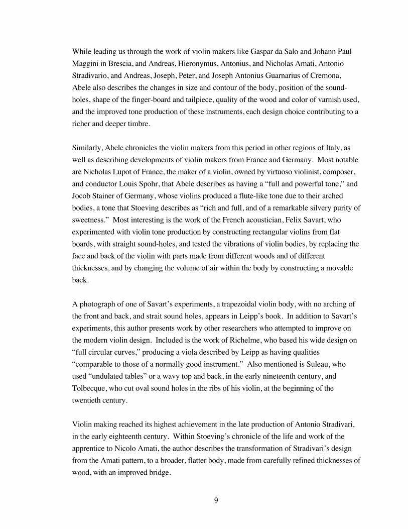
While leading us through the work of violin makers like Gaspar da Salo and Johann Paul
Maggini in Brescia, and Andreas, Hieronymus, Antonius, and Nicholas Amati, Antonio
Stradivario, and Andreas, Joseph, Peter, and Joseph Antonius Guarnarius of Cremona,
Abele also describes the changes in size and contour of the body, position of the sound-
holes, shape of the finger-board and tailpiece, quality of the wood and color of varnish used,
and the improved tone production of these instruments, each design choice contributing to a
richer and deeper timbre.
Similarly, Abele chronicles the violin makers from this period in other regions of Italy, as
well as describing developments of violin makers from France and Germany. Most notable
are Nicholas Lupot of France, the maker of a violin, owned by virtuoso violinist, composer,
and conductor Louis Spohr, that Abele describes as having a “full and powerful tone,” and
Jocob Stainer of Germany, whose violins produced a flute-like tone due to their arched
bodies, a tone that Stoeving describes as “rich and full, and of a remarkable silvery purity of
sweetness.” Most interesting is the work of the French acoustician, Felix Savart, who
experimented with violin tone production by constructing rectangular violins from flat
boards, with straight sound-holes, and tested the vibrations of violin bodies, by replacing the
face and back of the violin with parts made from different woods and of different
thicknesses, and by changing the volume of air within the body by constructing a movable
back.
A photograph of one of Savart’s experiments, a trapezoidal violin body, with no arching of
the front and back, and strait sound holes, appears in Leipp’s book. In addition to Savart’s
experiments, this author presents work by other researchers who attempted to improve on
the modern violin design. Included is the work of Richelme, who based his wide design on
“full circular curves,” producing a viola described by Leipp as having qualities
“comparable to those of a normally good instrument.” Also mentioned is Suleau, who
used “undulated tables” or a wavy top and back, in the early nineteenth century, and
Tolbecque, who cut oval sound holes in the ribs of his violin, at the beginning of the
twentieth century.
Violin making reached its highest achievement in the late production of Antonio Stradivari,
in the early eighteenth century. Within Stoeving’s chronicle of the life and work of the
apprentice to Nicolo Amati, the author describes the transformation of Stradivari’s design
from the Amati pattern, to a broader, flatter body, made from carefully refined thicknesses of
wood, with an improved bridge.
10
Because the bridge transmits the vibration of the bowed string to the violin body, the design
of the bridge and the strength and quality of wood used can have a great affect on the tone
of the violin. Kolneder credits Stradivari for crafting the modern bridge, although he
acknowledges Josephus Guarnarius del Gesù for improving the design. The author
explains that the decorative design in the center of the bridge serves to “increase elasticity
by reducing the amount of wood in the bridge without reducing its stability.”
Sandys describes this period in the development of the violin, that of Stradivarius and
Guarnerius, as the pinnacle of its design history. According to the author, despite the
subsequent years of experimentation and structural alterations, “there has been no
permanent or essential change since the latter part of the sixteenth century.”
Another author, George Hart, in his book, The Violin: Its Famous Makers and Their
Imitators (Hart 1978), agrees with Sandys’ assertion. According to Hart, only two
structural elements have been improved upon since the sixteenth century.
The only difference between the Violin of the sixteenth century and that ofthe nineteenth lies in the arrangement of the sound-bar (which is now longer,in order to bear the increased pressure caused by the diapason being higherthan in former times), and the comparatively longer neck, so ordered toobtain increased length of string.
In addition to chronicling the craft of violin makers from the Italian, French, German, and
English schools, Hart devotes a chapter to a discussion of the varnish used by the Italian
master violin makers, stipulating that its composition contributed not only to the visual
beauty of the instruments, but also to the tone quality. As stated by the author, the fine oil
varnishes used had a “soft and yielding nature,” that, when dried, left the wood “mellowed
and wrapped in an elastic covering which yields to the tone of the instrument and imparts to
it much of its own softness.”
History of the Bow
Like the violin, the bow has gone through considerable changes during the development of
its design. While examining the origins of bowed-string instruments in the Ravanastron,
Stoeving begins the discussion of the development of the bow, and sums up the importance
of the bow to the expression of the violin, in his imaginative style:
11
It is the bow first and the bow last, as every violinist knows; and yet the boweven – that magic wand in the had of a Paganini which opens wondrousworlds of sound – how easy an invention it really seems here, in its firstcrude form: the simple principle of producing sounds from strings byfriction, that is all.
Abele’s discussion of the development of the bow begins with that used to play the Rebek,
bent like an archer’s bow, with a piece of string or gut strung across. Continuing, Abele
describes the bow of the thirteenth century as having a less curved shape, and incorporating
a nut and head, suggesting the use of hair.
Van der Straeten also describes early bows as “not much more than the weapon from which
they derived their name,” providing an illustration of a crude symmetrical bow used in the
eighth to sixteenth centuries. Next to this illustration is another, showing a more developed
Crwth bow from the ninth century, also bent in a crude curve, but strung from the tip to a
point above the part of the stick that was left as a handle.
The same author also describes and illustrates a bow from the twelfth century that contained
a knob at the base of the stick, a design choice that appeared as a more elaborate notch in a
fourteenth-century bow, also illustrated in the book. Most interesting is a bow from the
thirteenth century that has the shape of a Baroque bow, with an angled head, and what
appears to be a thin frog.
Sandys declares that bows used to perform on viols of the twelfth century were “like that of
the double bass.” He does cite, however, the same bow as van der Straeten, that resembles
that used at the time of Arcangelo Corelli. This author attributes knowledge of this bow to a
painting, from the late fourteenth century, depicting a heavenly ensemble, by Barnabas de
Modena.
The most notable innovation in the design of the bow came in the fifteenth century, when a
system, which van der Straeten calls a Crémaillère, was developed to allow for the hair to be
tightened. The author illustrates both the crude fifteenth-century, and more elegant
seventeenth-century versions of this device, in which a wire loop, attached to the frog of the
bow, latched behind one of a row of metal teeth, that sat on top of the bow, at the end of the
stick.
This wire loop and metal teeth system was later replaced with a screw that tightened the hair
by drawing the frog back toward the end of the bow. This system, that is still used today, is

12
first known to have been used for a Viol da Gamba bow shown in the Harmonie
Universelle of 1634, by Marin Mersenne.
Also used in the seventeenth century was yet another system for tightening the hair of the
bow, in which the hair was secured to the bottom of the stick with a plug, and then tightened
by wedging the frog between the hair and the stick.
According to Abele, in the late seventeenth and early eighteenth centuries, Arcangelo Corelli
and Antonio Vivaldi used a bow even less curved than that of the thirteenth century, with a
sloping head, and a separate frog, secured by the same wire loop and metal teeth system
described above. Because the violin music of the mid to late eighteenth centuries required a
more agile bow, they were made from lighter wood, with a straight stick. Nicolas Pierre
Tourte improved the design further, by crafting a head that allowed the hair to lay in a more
regular swath, while his son, François Xavier Tourte, fixed the dimensions, balanced the
weight, and broadened the width of hair on the violin bow.
Van der Straeten also attributes Tourte with the innovation of using the best Brazil wood,
which the author calls Pernambuco, for all of his bows, and inventing, perhaps at the
suggestion of Giovanni Battista Viotti, the slide and ferrule, which broaden and secure the
hair at the bottom of the frog. The same innovation seems to have been simultaneously
invented by an English bow maker named John Dodd.
The above discussion is meant to illustrate that, although some design choices of instrument
builders were made for aesthetic reasons, most contributed to the expressive potential of the
developing bowed-string instrument, culminating in the design of the modern violin. The
vBow is an extension of this pursuit, to design an instrument that provides the performer
with an amplification of their musical intent, through the translation of their physical gesture
into the expressive manipulation of timbre. A similar study of evolving expressive potential
can be made from the perspective of the performer, and in particular, the developmental
history of violin bowing.
It is difficult to discern whether the demands, on the performer, of more expressive music
lead to the development of advanced techniques, which in turn prompted changes in the
design of the violin bow, or if performers and composers took advantage of the
improvements of the instrument. Either way, there has been considerable evolution of
bowing style and technique since the sixteenth century.

13
History of Bowing
In his article, Differences Between 18th Century and Modern Violin Bowing (Babitz, 1970),
Sol Babitz discusses this evolution, starting with the eighteenth century. The bow from this
period had a substantially different design from the modern bow. The early bow had much
more curve to the stick, giving the hair much less elastic resistance than a modern bow. This
pronounced curve results in a distance between the stick and the hair that is twice that of the
modern bow, producing what Babitz describes as a “natural springiness.”
Because of the inherent spring of this early bow design, the technique used by the
performer was considerably different than that used with the modern bow. In addition to
holding the bow further up the stick than the modern bow grip, Babitz instructs that the
performer played each note with a dynamic swell and decay, because of the varying
elasticity along the length of the bow.
Because of this initial slackness or ‘give’ of the hair, the early bow does notproduce its full tone at the first contact of the hair with the string, but onlyafter some finger pressure has been exerted while starting the stroke. Thisapplication of pressure to the point where the hair will be sufficiently tensedto play a full tone causes a momentary softness, followed by a crescendo tothe full tone at each stroke. By changing the finger-pressure it is possible toproduce a variety of crescendi, ranging from the slow and gradual to thesudden and accented.
In contrast, the modern bow has a much thinner design, providing much less spring than the
early curved model, resulting in what Babitz describes as a “clinging-to-the-string, even
motion,” when bowing. Because the elasticity of the modern bow is much more consistent
along its length, there is no difficulty producing a strong tone from the start of the bow
stroke at the frog, to the end at the tip. Consequently, there is no natural crescendo and
decrescendo when using a modern bow. Because the modern bow imposes less of an
inherent dynamic limitation on the performer, its design provides a greater expressive
potential.
What is common between the modern and early violin bow is the primary contribution it
plays and played in the execution of an expressive violin tone, even if what was considered
appropriate expression has changed between stylistic periods. Babitz describes the bow of
the eighteenth century as “the primary source of emotional expression,” ideal for the
singing and oratory effect of the Baroque Affektenlehre, or doctrine of the affections.
14
David Boyden discusses the developmental history of violin bowing further in his book,
The History of Violin Playing from its Origins to 1761 (Boyden 1975), starting with the
violin and bow of the sixteenth century. Before writing about how the bow of the sixteenth
century was held and drawn, Boyden describes the general design of this early bow.
The length, weight, and shape of individual bows varied greatly, and the oldbow in general differed from the modern bow in several important points ofconstruction. The stick of the old bow curved outward and away from thehair, although the degree of curvature was an individual matter; and the hairwas probably strung at fixed tension, not adjusted or adjustable by a screwas in later bows. Compared to the modern bow, the ribbon of hair on the oldbow was narrower, and this combined with lower tension and the (generally)shorter length of the bow, made for a smaller volume of tone. The shape ofthe head and the nut of the old bow also differed from our bow today.
This author continues by speculating that the balance, which was very close to the frog,
made it difficult to produce a strong articulation or tone, when bowing at the tip. This, along
with the drastic arc of the stick and slack hair, allowed for an early bowing technique
consisting of short halting strokes, articulating separated notes. This style of bowing, which
Boyden describes as producing a feeling of “light and air” with “greater breath between
the phrases,” would have been appropriate for the dance music performed and the singing
emulated by these early performers. According to Boyden, this design and early bowing
technique contributed to the production of a “relaxed and smaller tone” on the violins of
the sixteenth century.
Boyden contrasts the bow grip of the early violin, palm down, with the weight of the arm
transferred to the bow, with that of the viol, palm up, with tension exerted on the hair with
the second and third fingers. Because the lengths of bows varied, requiring more or less
control, and the fixed hair tension of the time often required adjustment while playing,
thumb position also differed between players. French players are depicted with their thumb
under the hair, while Italian players are shown with their thumb between the stick and hair of
the bow.
In a quote from Sylvestro de Ganassi’s treatise, Regola Rubertina, dated 1542-3, Boyden
reveals that timbral differences due to bow position were also considered in the sixteenth
century.
15
… the distance of the bow from the bridge is determined by the kind ofeffect and tone desired: well away from the bridge and near the fingerboardfor sad effects; near the bridge for stronger and harsher sounds; and inbetween for normal playing.
Again concerned with the expression resulting from bowing technique, the treatise instructs
the player to adapt their bow velocity to the style of music performed.
Energetic bowing is recommended for lively pieces, and more relaxedbowing for music of greater expression …
But, despite the development of bowing technique to this basically expressive level, Boyden
believes that, at the start of the seventeenth century, the violin represented an “undeveloped
potential for personal expression throughout a wide range of diverse use.” This
unexplored expressive potential would begin to be charted through the seventeenth century,
with the help of a refined bow design, and the development of an idiomatic style.
According to Boyden, aside from some decorative elements, the design of the violin was left
unchanged during the early seventeenth century. Instead, improvements were made to the
design of the bow. Relying on illustrations and descriptions from treatises such as Michael
Praetorius’ Syntagma Musicum and Marin Mersenne’s Harmonie Universelle, the author
describes how design elements of the bow were not standardized, early in the seventeenth
century. For instance, short bows were used for dance music, while longer bows were used
to perform sonatas.
Improvements to the design of the bow, during the seventeenth century, included
lengthening the bow stick, and consequently the playable area of the hair; developing the
screw and movable frog, for tightening the hair; making a distinct tip or head at the top of
the bow stick, allowing for more bow control; and straightening and tapering the stick,
making the bow lighter and more flexible.
As Boyden writes, these improvements to the design of the bow, were motivated by
seventeenth century composers, from the areas of Europe known for violin making, such as
Claudio Monteverdi, himself a string player, born in Cremona, and later working in Venice,
who advanced the idiom of violin music, writing pieces that demanded greater technical skill.
All these changes were ultimately caused by musical requirements, especiallyin Italy, where new instrumental forms like the sonata inspired bow makers

16
to produce a longer bow capable of more subtle bow strokes, greater varietyof tone, and an increased range of expression and dynamics.
Some examples of idiomatic violin effects, made possible by improvements of the bow’s
design in the seventeenth century, include tremolo, used by Monteverdi for his measured
“stile concitato” or excited style, and, according to Boyden, unmeasured by Carlo Farina in
his Capriccio Stravagante; and col legno, an effect where spiccato notes are played on the
violin, with the stick of the bow. Also noteworthy are passages of sometimes slurred
elaborately ornamental sixteenth and thirty-second notes, often including fast string
crossings, which were called passaggi, and independent obbligato parts for the violin,
accompanying the vocal parts in operas.
Other seventeenth-century composers continued to expand the technical demands placed on
the violinist, including Italy’s Arcangelo Corelli, who used bariolage, a rapidly alternating
string-crossing effect, as well as sustained crescendo and diminuendo, in his many sonatas,
and Germany’s Heinrich von Biber and Johann Jakob Walther, whose variations included
slurred staccato, arpeggiando across strings, and ondeggiando, an undulating slurred string-
crossing.
In the eighteenth century, the bow, which Boyden entitles the “soul” of the violin, was
perfected by François Tourte, attaining a standardized design that has not changed
significantly, since. Some of the standardized design elements included setting the length of
the violin bow to twenty-nine and a half inches, allowing for twenty-five and a half inches of
playing surface; bending the stick into a concave curve, providing a stronger, more resistant
response; crafting a larger, higher, and heavier tip or head, moving the balance point closer
to the middle of the bow; and widening the hair, making it lie flat on the string.
Eighteenth-century composers, such as Antonio Vivaldi and Johann Sebastian Bach, took
advantage of this improved, standardized bow design, by writing concertos and solo sonatas
that required a powerful solo tone that could rise above the accompanimental orchestra, and
more subtle control over timbre and dynamics. Some of these subtle bowing effects
included smooth bow changes, expressive crescendi or diminuendi produced from
variations in bow pressure, changes in bow speed to increase or decrease loudness, and
more complex combinations of slurs and staccato markings, requiring a diversity of bow
strokes. This diverse set of bow strokes included a variety of short, separated staccato
effects, played both on and off the string.

17
The need for expressive potential in the design of musical instruments has now extended
beyond acoustics to electroacoustics in the need for greater expression in the performance
of computer music. In direct response, the vBow has been designed to accurately sense the
bowing gesture with acute resolution, in order to expressively, physically manipulate the
parameters of digital synthesis. The importance and difficulty of expressive performance of
electroacoustic music has been discussed by a number of leaders in the computer music
community.
Expression in Electroacoustic Music
In an article edited by Stephen Pope, Carlos Cerana, an Argentinean composer and
researcher, asks the question, “could a music touched by machine touch us?” (Pope 1995).
The concern Cerana raises in his essay is that electroacoustic compositions realized with or
by a computer “have no relation with the body, that is, with the human way of connecting
with the world.” It may be difficult for an audience to connect with or derive expression
from this category of electroacoustic composition, in which the computer is both the
compositional tool and performer.
Chris Brown, a composer teaching at Mills College, shares in Cerana’s concerns (Brown,
Bischoff, and Perkis 1996). In an article entitled “Bringing Digital Music to Life,” Brown
states that the difficulty in composers realizing their pieces with software is that, in addition
to having to build their own instruments, the instruments computer music programmers
build are no longer physically performed. With the exclusion of a physical interface, the
expression of this category of computer music no longer relies on the musicianship and
technical skill of the performer, but rather on the sophistication of the programming.
The composer has become an instrument builder, but the instruments areethereal genies. … there is no implied relationship to the body; theseinstruments are concepts, … and so interface is arbitrary. … This may bethe most limiting factor in the development of this instrumentation – a non-arbitrary physical interface provides the stability that allows a performer todevelop a repertoire of intuitional responses to sound that is responsible forthe liveliness of traditional instrumental performance. It isn’t just that weneed the technological means for controlling multiple simultaneousparameters of sound. We also need some physical reason for developingthese means, which will allow the intelligence of the body to enter the music.
One obvious remedy for the artificial or disembodied nature of computer-generated music is
to include a live performer in the composition. With the addition of a physical interface to
18
the computer-music system, the composition again relies on the intuition of the player for
the expression of the performance, a source to which the audience can relate.
But, this interaction between human performer and computer, as perceived by the audience,
is a tricky consideration. In an overview of “ways the computer can participate in live
performance,” entitled “Who’s Playing?: The Computer’s Role in Musical Performance,”
Alan Belkin raises some concerns about how the perceived interaction between the
performer and computer in an electroacoustic composition can affect the relationship
between the performer and audience (Belkin 1991).
This relationship, which is central to the concertgoer’s expectations, andwhich indeed constitutes the main difference between live and recordedmusic, deserves serious consideration. When I go to a live concert I enterinto communication with the performer, and through him, with the composer.If the performer becomes anonymous or seems disconnected from what Ihear, I will find him irrelevant.
If the audience does not recognize the interaction between performer and computer music
system, if there is no perceived correlation between performance gesture and musical result,
then the experience of the audience is no more connected to or informed by physical
performance than when listening to a piece for computer-generated sound.
Christiane ten Hoopen, while a student at the University of Amsterdam, wrote that this issue
of “source identification” is “a crucial aspect in the comprehension of electroacoustic
music” (Ten Hoopen 1992). Although Ten Hoopen does not seem concerned by the loss
of a perceived “connection between sound and source,” a phenomenon which he labels as
“one of the innovative aspects of electroacoustic music,” he describes this experience in
contrast to the clear association between instrument or voice and musical production in
“traditional Western art music,” a relationship he states “has been challenged by
contemporary music and destroyed by the electroacoustic medium.”
Listeners can be confronted with sounds of ambiguous provenance orsounds can exhibit plural sources. In certain cases we may even experiencesounds which have no apparent linkage to sources by behaving ordeveloping in such a way that listeners cannot think of a rational explanationof what their origins might have been.
Similarly, in a paper, entitled “Live and In Concert: Composer/Performer Views of Real-
Time Performance Systems,” Jon Appleton calls “the need to have the audience understand
the musical parameters being controlled in performance,” “a major issue faced by all

19
performers of electroacoustic music,” and quotes composer, Morton Subotnick as stating
that “the audience does not know what the composer is controlling on an electronic
instrument, so that the difference between live performance and a disk, or something that is
going on in the background, is really not clear” (Appleton 1984).
So, the addition of a human performer does not assure that the audience will relate to the
musical expression produced by the computer-music system. But, Belkin suggests that
building an electroacoustic performance system, in which the function of the player is
similar to that when performing acoustic compositions, namely “subtle control” of sound
with “finely tuned physical gestures,” could result in heightened electroacoustic musical
expression, which he, like Brown, calls “liveliness.” Belkin’s proposed system, like the
vBow, takes advantage of the training of the classical musician.
The performer’s ability to subtly control aspects of sound with finely tunedphysical gestures, and to hear delicate nuances in the resulting music iscultivated from years of training. If this sensitivity and training are not to bewasted, the performer must be allowed to use his strengths in meaningfulmusical ways. The performer’s gestures may be translated by the computerto affect novel aspects of the sound. If this is sensitively applied, theresulting performance can have a new vibrancy and liveliness.
In response to similar concerns about the “cause-and-effect relationship in live
performance,” composers and performers, Andrew Schloss and David Jaffe, developed an
interactive performance system for their collaborative piece, Wildlife (Schloss and Jaffe
1993). Under an assumption that “one of the significant aspects of live performance (from
the point of view of the audience) is virtuosity, and that there is a danger that perception of
virtuosity may erode as new technologies are applied to musical performance,” the duo
created an interactive system, using a Mathews/Boie Radio Drum, Zeta violin, and
computers, in which the two performers could control the musical output of the other’s
instrument, as well as that generated by the computer, in an improvisatory context.
Like Belkin and Ten Hoopen, Schloss and Jaffe were concerned that, while “real time
music systems (like MAX and the Music Kit) have greatly increased the power of the
player”, they have, at the same time, “exacerbated the issues of clarity in performance.”
Controlling sound on the timbral level typically requires great skill, but it isusually very clear what the intention of the player is (e.g. vibrato orglissando) – there is little danger of the audience’s losing site [sic] of themeaning of a performer’s gesture. Unfortunately, most current controllers
20
do not always fare well in this domain, primarily due to the influence of thekeyboard-orientation of MIDI.
These authors name “the impoverishment of the MIDI specification” as a principal reason
for the loss of virtuosity among players of new controllers. Not only does the use of some
electronic controllers in the performance of electroacoustic music cause confusion for the
audience, but also these instruments limit the expression of the player. Schloss and Jaffe
cite the case of the MIDI wind controller, which is “vastly less powerful than real
instruments in terms of nuance of control.”
Even though they may be connected to powerful synthesizers, they tend tobe less expressive than their acoustic counterparts. In particular, they havelimited refinement in their control of pitch, timbre, and dynamics.
Their solution to the challenge of preserving the tradition of virtuosity in the performance of
electroacoustic music, made worse by the limited expressive potential of MIDI controllers,
was to create a system, where “all materials are generated in direct response to the
performers’ actions,” and the players were able to improvise their own part, while, at the
same time, influencing the musical output of the other instruments and computers, with the
MIDI output of their controllers.
In the same article by Appleton, mentioned previously, William Buxton also describes the
limitations imposed on the performer by electronic musical instruments, although MIDI is
not explicitly mentioned, in this early paper. The Canadian designer and researcher is
quoted as saying that “a major problem of synthesizers to date, especially recently, is that
they constrain the performer to expressing ideas through a limited set of gestures.” He
states that often “the medium of expression” of these synthesizers is “at odds with the
musical idea.” Because of this, in his instrument designs, he strives to “enhance our ability
to capture physical gesture and map it to sonic gesture,” a goal I share in the development
of the vBow.
The expressive limitations imposed on the performer of MIDI instruments is elaborated
upon by F. Richard Moore, in his landmark paper, “The Dysfunctions of MIDI” (Moore
1987). Like Schloss and Jaffe, Moore believes that the ability to subtly control musical
expression is a vital characteristic of any performance system.
We are acutely sensitive to the expressive aspects of sounds, whereby aperformer is able to make a single note sound urgent or relaxed, eager or
21
reluctant, hesitant or self-assured, perhaps happy, sad, elegant, lonely, joyous,regal, questioning, etc. The more a musical instrument allows such affects tobe reflected in the sound spontaneously at the will of the performer, the moremusically powerful that instrument will be.
This characteristic of an instrument, its ability to correlate “the variety of musically
desirable sounds produced and the psychophysiological capabilities of a practiced
performer,” which I call expressive potential, Moore names “control intimacy.”
Moore cites the violin as good example of an instrument “exhibiting large control
intimacy,” explaining that instruments like the violin “allow the performer to evoke a wide
range of affective quality in the musical sound,” by mapping “the microgestural
movements of the performer’s body” to sound producing parameters. Moreover, the
author states that, to emulate the expressive potential of the acoustic violin with an electronic
controller, these mappings must be consistent and timely, especially when dealing with
“continuously variable control functions,” such as vibrato or crescendo.
Controlling these varying synthesis parameters with MIDI is made difficult by the limited
bandwidth, or amount of data that can be transmitted within a given time, of the protocol.
The bandwidth of MIDI would be sufficient for transmitting the continuous data generated
by vibrato changing the pitch of the violin string, but there would be no bandwidth left to
represent any other “realtime performance control parameters.” Because of this limitation,
data is often “clipped” or rejected when the maximum bandwidth is exceeded, reducing the
expression of the performance to a level that the MIDI protocol can transmit in time.
Furthermore, transmission of MIDI data from a controller is subject to delays and
fluctuations in transmission time, limiting the subtle expressive control of the performer.
Often, to compensate for this latency, “the information for complex events may be
precomputed so that it may be stored inside the synthesizer and simply triggered when it is
needed,” limiting the expressive control of the performer over the sound synthesis output of
the instrument. These are the very reasons that the vBow uses parallel data streams, from
the encoders at the back of the servomotors, to the ServoToGo data acquisition card, instead
of a serial MIDI stream, to transmit sensor data to parameters of the sound synthesis
programming.
Despite these limitations of MIDI instruments, Moore makes a case for the development of
controllers for the performance of computer music, based on the need for a physical
22
interface to sound synthesis, stating that the “physical capabilities of human performers are
simply too magnificent to be ignored altogether in any form of musicmaking.” In addition,
he acknowledges the importance of haptic feedback to instrumentalists, and seems to
suggest the inclusion of force feedback in the design of musical controllers.
For subtle musical control to be possible, an instrument must respond inconsistent ways that are well matched to the psychophysiological capabilitiesof highly practiced performers. The performer must receive both aural andtactile feedback from a musical instrument in a consistent way – otherwisethe instrumentalist has no hope of learning how to perform on it in a musicalway.
The limitations, imposed on the performer by the MIDI protocol, also concern Simon
Emmerson, from City University, in London (Emmerson 1991). According to the author,
quantizing sensor data to fit within the range of MIDI pitch and velocity values and limiting
sensor readings to the resolution of “discrete clocked time,” impoverishes “the
analysis/transduction process.” Instead, Emmerson suggests that “high resolution data”
be used, and that “controller-produced value ranges match the range of parameter values to
be controlled.”
Like Schloss and Jaffe, Appleton is concerned with the virtuosity or performance practice of
electroacoustic music (Appleton 1986). In an article entitled “The Computer and Live
Musical Performance,” the composer discusses the importance of musical interpretation in
a performance, stating that “perhaps the most crucial aspect of live performance is the
unique character of the event itself,” a quality that is lost when electroacoustic music is
performed by a computer or played from a tape or CD. But, while he recognizes the
importance of interpretation to the audience’s enjoyment of a performance, he
acknowledges that, because the gestures of electroacoustic are still new to us, the
interpretation of electroacoustic music may be lost on us. His hopeful conjecture is that “as
a repertoire develops a performance tradition will follow; a performance tradition in the
widest sense of the word, encompassing both the performer’s technique and the audience’s
understanding of same.”
For Joel Chadabe, this new performance practice of electroacoustic music involves placing a
performer in “an unusually challenging performing environment” (Chadabe 1983). The
system that he describes is similar to that developed by Schloss and Jaffe, in which the
performer and computer share control over the music generated.
23
An interactive composing system operates as an intelligent instrument –intelligent in the sense that it responds to a performer in a complex, notentirely predictable way, adding information to what a performer specifiesand providing cues to the performer for further actions. The performer, inother words, shares control of the music with information that isautomatically generated by the computer, and that information containsunpredictable elements to which the performer reacts while performing. Thecomputer responds to the performer and the performer reacts the computer,and the music takes its form through that mutually influential, interactiverelationship.
But, in response to the same concerns expressed by Belkin and Ten Hoopen, Chadabe
recommends that, in addition to being interesting, informative, new, and unexpected, the
response of the electroacoustic performance system must be “recognizably related to the
performer’s actions,” not for the sake of the audience’s enjoyment, but to make the
interaction meaningful for the performer. He likens this performance practice to a
conversation, where both parties have shared control over the resulting expression.
Johannes Goebel takes issue with using the term “interaction” to describe a system
“where one side is not alive” (Goebel 1988). For this researcher, the term is used
optimistically to describe not the current state of interactivity, which he more accurately
terms “man-machine reaction,” but rather a future “realm of mutual, reciprocal action
between two partners who act on the ground of equal potential.”
This issue of “what do computers bring to live performance” as well as the reciprocal
question of “what does live performance bring to computer music,” is at the foundation of
Guy Garnett’s paper, “The Aesthetics of Interactive Computer Music” (Garnett 2001).
For this composer and researcher, the importance of incorporating the use of computers into
a piece of interactive electroacoustic music lies in the ability of the computer to extend the
performance capabilities of the human. And furthermore, whether the computer is
processing the signal from an acoustic instrument, using data from sensors added to an
acoustic instrument to enhance the performance, or mapping sensor data directly to sound
synthesis parameters, this extension of human performance represents, for Garnett, an
essential aesthetic response to current technology.
To make music with the technology of our time, and specifically thecomputer, poses a tremendous challenge for the artist. To address thischallenge, in itself, will help keep music alive and significant. To addressthis challenge in a way that acknowledges, directly and deeply, the humanproduction of that music brings together into a new art form the diverse
24
elements of performance, with its millennia of history, and the age of thecomputer, with its bare decades of history.
Similarly, for this author, the importance of the inclusion of a human performer in the
presentation of a piece of electroacoustic music lies in our ability to add “gestural nuance
such as rubato, subtleties of phrasing and articulation, and dynamics” and interpretation to
the work.
Composer and researcher, Cort Lippe also asks how the computer contributes to live
performance, in his paper, “A Look at Performer/Machine Interaction Using Real-Time
Systems” (Lippe 1996). The answer to his specific question, “can the computer have a
unique function in a real-time concert situation?” appears to be no. According to the
author, “the computer appears to be a useful tool for creating new sounds, transforming
pre-existing sounds, and controlling algorithmic compositional structures,” none of which
exclusively require the functionality of the computer. In the case of the vBow, and similar
sensor-based instruments, however, I would argue that the ability to program both how the
instrument sounds and feels, can only be done with a computer, making its function in this
interactive computer music context unique.
In support of Goebel’s concern, Stephen Horenstein, from the Jerusalem Institute of
Contemporary Music, writes in his paper, “Interactive Works: New Problems and
Potentials,” that this new electroacoustic performance practice requires “new physiological
techniques” to produce “a spontaneous, expressive performance” (Horenstein 1995).
Because the player must incorporate “foreign gestures into his technique vocabulary” to
ensure that the computer tracks the performance, the “expressive realization” of the piece is
inhibited.
For the computer to track the performer’s input properly, the performer isoften required to execute exaggerated tonguing, forced extreme dynamicchanges, slower unnatural speeds, minimized use of pitch bend nuance, andreduced timbre change. These necessary restrictions can easily detract fromthe performer’s natural expressivity. The performer’s comprised“adapting” to such restrictive environments is one of the unfortunate resultsof this process.
In order to adapt to the difficulties of this new performance practice, Horenstein envisions
making these extended techniques a part of instrumentalist’s training, to foster “the vital
importance of the human performer and his innate creativity,” in the performance of
interactive electroacoustic pieces.

25
In her article, entitled “Performance Practice in Computer Music,” violinist and composer
Mari Kimura addresses many of these issues faced by performers of electroacoustic music
(Kimura 1995). Of particular interest is her discussion of problems encountered when
performing interactive computer music. In two specific and in-depth case studies, the author
outlines the difficulties she had with interactive performance systems for Robert Rowe’s
piece, Maritime, and her own, “U” (The Cormorant). In both cases, limitations in the
technology interfered with her expressive interpretation of the piece.
For her piece, “U”, the violinist experienced difficulties when pitch-tracking an acoustic
violin amplified with a microphone. Because the microphone amplified the upper
harmonics of the violin, a problem that was exacerbated by the live acoustics of the hall, the
pitch tracker was unable to accurately translate the notes of the violin into MIDI data. Since
Kimura had programmed safeguards into the piece, such as triggering the computer-
generated music with a particular series of pitches from the violin, the problems with pitch
tracking had a devastating effect on the performance of the piece. In order to compensate
for the limitations of the technologies used for the work, the composer had to reprogram the
piece, often sacrificing her musical ideas for technological logistics.
The violinist’s problems, when performing Rowe’s Maritime, arose from the limitations of
the Zeta MIDI violin used. Despite the capability to fine-tune the response of the system,
Kimura found the level of control over pitch and dynamic “incomparable to that of the
acoustic violin.” Furthermore, the limited capabilities of the pitch-to-MIDI converter
required that she restrict the expression of her bowing gesture.
…it is unfortunate that in playing Zeta violin, one of the most essentialelements of string playing, the sensitive art of controlling the articulation,might have to be sacrificed to adjust to the capability of MIDI and pitchtracking. For string instruments, the bow is what creates articulation. Itwould be interesting to see more development in computerized bows, ratherthan motion sensors attached to the fingerboard or a bow arm.
Kimura describes additional problems with the pitch tracker, incorrectly identifying notes
played on the violin, because of the “complicated harmonic structure” of the instrument,
transposing the octave of low pitches, and being unable to track accented strokes.
According to Miller Puckette and Zack Settel, these complications, inflicted on the player by
interactive computer music systems, may actually enhance their performance (Puckette and

26
Settel 1993). Citing Freud’s theories about the conscious and unconscious mind, these
authors believe that diversions such as crashing computers, errant pitch trackers, foot pedals
for synchronizing the player with the computer, video monitors, flashing lights, or click
tracks for keeping time, wearing homemade equipment, short cables limiting movement, and
poor monitor levels, facilitates the influence of the unconscious mind on the performance,
improving the expression of the piece.
In diverting the performer’s thoughts from the details of the violin part, tothe agonizing question of whether the machine was following correctly (andwhether it would work at all,) the presence of live electronics may actuallyhave improved the violin playing.
Despite this possible psychological benefit realized from the challenge of performing with
machines, Puckette and Settel acknowledge that new musical interfaces should “make
sense” to the performer, taking advantage of the “years of training and experience” of the
player. In addition, they recommend that, since “for controlling articulation, only physical
feedback is fast enough,” new musical controllers should provide force feedback.
Guy Garnett and Camille Goudeseune, at the University of Illinois at Urbana-Champaign,
have approached the problem of ensuring that a new musical controller makes sense to the
performer, not by developing a better instrument, but “by improving tools for
understanding and designing the mappings between the physical interfaces and resultant
sounds” (Garnett and Goudeseune 1999). Using an interface that included “an electric
violin tracked continuously in pitch, amplitude, and full spatial position/orientation of bow
and instrument body,” which enabled “a trained violinist to feel relatively ‘at home’ with
the instrument,” the team worked to map physical gestures to sound synthesis, in ways that
simplify “the performer’s idea of the instrument and the sounds it produces without
impoverishing the sonic output or overloading the attentive capacity of the performer.”
Taking advantage of the practiced technique of the violinist avoided the need for physical
retraining, and clarifying the mapping between physical gesture and sound synthesis
parameters prevented the need for cognitive retraining.
In order to keep these simplified mappings musically interesting, Garnett and Goudeseune
used a “geometrical, numerical mapping,” called “simplicial interpolation,” to correlate
gestures to sound. The result was an ability to map one control parameter to many sound
synthesis parameters or many control parameters to one sound synthesis parameter.

27
One of David Wessel’s ideas for future improvements in computer music technology, as
expressed in his article, “Instruments That Learn, Refined Controllers, and Source Model
Loudspeakers,” is musical controllers that use “very small and unobtrusive musical
instrument transducer systems,” such as pressure sensors and accelerometers made from
“microdynamic silicon structures with moving parts,” that combine “high-performance
sensors” with “on-chip circuits for the processing of the sensor data” (Wessel 1991).
According to this composer and researcher, this new technology would allow for “new
generations of alternate controllers,” as well as “adapting traditional acoustic instruments to
be effective controllers.”
For Wessel, development of a refined musical controller from this technology would
facilitate an improvement in the “control intimacy,” or “tight coupling between gesture and
instrumental response,” of the instrument, something that this author considers “one of the
critical missing elements” in current computer music technology.
The use of traditional instruments as controllers shows promise, but thereare still problems with pitch extraction, the keyboard bias of the MIDIspecification and its bottleneck data rate, and the fact that it is still verydifficult to readily outfit a musician’s preferred instrument, be it aStradivarius or a Gibson guitar, with the acoustic and positional gesturesensors that are required to make it a refined controller.
This coupling between gesture and feedback is also the subject of Marcelo Wanderley’s
paper, “Gestural Control of Music” (Wanderley 2001). Specifically, this researcher is
concerned that “new computer-based musical instruments – consisting of gesturally
controlled, real time computer-generated sound” be designed so that they “obtain similar
levels of control subtlety as those available in acoustic instruments.” In order to do so, the
author suggests that electroacoustic musical instrument designers recognize their connection
to the study of “human-computer interaction.”
Gestural control of computer generated sound can be seen as a highlyspecialized branch of human-computer interaction (HCI) involving thesimultaneous control of multiple parameters, timing, rhythm, and usertraining
Wanderley divides the electroacoustic performance system into the “gestural controller” or
instrument hardware, “sound generation unit” or synthesis software, and “mapping layer”
or routing of performance gestures through controller outputs to synthesis parameters, a
separation that is not possible for acoustic instruments. Each of these three components
28
must be considered when designing a new electroacoustic instrument, or musical human-
computer interface.
According to Wanderley, the musical controller should be designed with the gestures of the
instrumentalist in mind. In the case of the vBow, the interface was designed around the four
primary component gestures of bowing a violin string: lateral, rotational, vertical, and
longitudinal motion.
Similarly, the author states that when studying performance gestures, in preparation for
designing a musical controller, “it is also important to be aware of the existing feedback
available to the performer, be it visual, auditory or tactile-kinesthetic.” The vBow was
designed to simulate the auditory and tactile-kinesthetic feedback expected by the player of
an acoustic violin.
When choosing a mapping strategy for an electroacoustic musical controller, both the
output of the controller and the parameters of the sound synthesis should be considered.
How the instrument output is routed to the sound input will vary depending on what type of
synthesis is used. The author states that “for the same gestural controller and synthesis
algorithm, the choice of mapping strategy may be the determinant factor concerning the
expressivity of the instrument.” By changing mapping strategies of controller outputs to
synthesis parameters from one-to-one, one-to-many, and many-to-one, while keeping the
controller and synthesis parameters consistent, the researcher discovered that “different
mappings did influence the expressivity obtained during the playing.”
In his discussion, Wanderley mentions the obvious direct, one-to-one mapping strategy
represented by routing the vBow sensor output to the parameters of a bowed-string physical
model.
For the case of physical models, the available variables are usually the inputparameters of an instrument, such as blow pressure, bow velocity, etc. In asense the mapping of gestures to the synthesis inputs is more evident, sincethe relation of these inputs to the algorithm already encompasses themultiple dependencies based on the physics of the particular instrument.
Because the vBow and bowed-string physical model were both designed around the
composite gesture of bowing on a violin string, a direct mapping between sensor output and
sound input was an obvious and convenient choice.
29
Finally, Wanderley weighs the pros and cons of using a physical model versus a signal
model for the synthesis of an electroacoustic musical controller system. While physical
models allow a “realistic simulation of a given acoustic instrument,” they also present a
“complexity” in real-time performance, an aspect of the bowed-string physical model that
the vBow is designed to explore. Signal models, like additive synthesis simulations of
instrumental timbres do not provide the “full behavior of the original instrument,” but do
offer the flexibility of “continuous transformations between different instruments,” another
interesting performance scenario that the vBow is equipped to investigate.
As Moore and Wanderley alluded to, instrumentalists respond to both aural and tactile
feedback, when performing on their instrument. The usefulness of this haptic feedback can
be evaluated by whether or not the kinesthetic response of the system assists with the
playability of the instrument. Force feedback is useful if it provides the performer with cues
that support the acoustic response of the instrument or sound synthesis output of the
controller, so that the performance can be judged cross-modally by the player. The vBow
has been designed to provide this haptic feedback to the performer, by simulating tactile
cues, with the use of servomotors and cable systems. The importance of these cues, to
musical performance, has been researched by scientists studying the interaction between the
player and instrument.
Musical Haptics Research
Claude Cadoz, Leszek Lisowski, and Jean Loup Florens write about the importance of
haptic feedback to an instrumentalist, in an article describing the development of their
“modular feedback keyboard” (Cadoz, Lisowski, and Florens 1990).
The standard gestural instrument-performer relationship is bidirectional.This indicates both a transmission … and a reception: at the very moment ofthe instrumental gesture, a tactilo-proprio-kinesthetic perception takes place.This in turn informs us of the nature of the object we are manipulating andhow it behaves. It also provides us with manipulation possibilities and evensignals the nature of the sound phenomenon itself.
This haptic relationship between performer and instrument has been scientifically studied,
by a number of researchers. In their seminal study of tactile feedback from acoustic
stringed instruments, Anders Askenfelt and Erik Jansson, at the Royal Institute of
Technology in Stockholm, studied vibration levels in the violin, as well as the double bass,
guitar, and piano, and finger forces on the bow, as well as the piano key (Askenfelt and

30
Jansson 1992). These scientists wondered if vibrations of stringed instruments are
perceived by the player, and, if so, if they assist with performance. In addition to these
pragmatic questions, Askenfelt and Jansson conjectured whether or not these vibrations add
to the pleasure of playing, and speculated if players of electronic instruments are missing
part of the performance experience.
… a provoking question to ask is whether or not the vibrations cancontribute to the excitement of playing. Could it be that the vibrationsconvey a feeling of a resonant and “living” body? If so, the design ofmodern instruments, which rely on electronic devices to generate sound,could possibly be improved. By supplying additional vibration to the player,not required for actual sound generation, the “vibratory quality” of thetraditional instruments could be mimicked.
For their study, Askenfelt and Jansson placed miniature accelerometers on the top plate of
the violin, just below the left f-hole, a position that corresponds to the maximum of the
lowest mode of vibration, as well as on the back plate, where the shoulder makes contact
with the violin, and on the chin rest and neck of the violin. They also measured vibrations
on the bow, with accelerometers placed at the back of the frog, to measure longitudinal
vibrations, and on the bottom of the frog, to measure transverse vibrations.
For the range of frequencies in which fingertips sense vibration, below 1000 Hz and
strongest at 250 Hz, the researchers measured vibrations within a 20 dB range, from pp to ff.
The measurements indicate that vibrations transferred from the chin rest to the chin, the back
plate to the shoulder, and the neck to the hand, are perceptible throughout the frequency
range, or while playing all strings of the violin, and vibrations transferred through the frog to
the bow hand, can be detected for low frequencies, or while playing the bottom two strings
of the violin.
In addition to the vibrations detected by the player, the kinesthetic forces produced by the
interaction between the bow and strings, and fingers and strings, are sensed by the player,
and may be used to assist with timing in performance. These forces, the vertical “bow
force” of the bow pushing against the strings, and the lateral “drawing force” of the bow
pulling the strings, were measured by Askenfelt and Jansson, who speculate that the initial
resistance and release of the string, during a bow stroke, and the inertia of the bow and hand,
during changes in bowing direction, may provide timing cues to the performer.

31
Two researchers at Stanford University’s Center for Computer Research in Music and
Acoustics (CCRMA), Chris Chafe and Sile O’Modhrain, have conducted a number of
experiments on musical tactile feedback. By comparing recordings of his Celletto electronic
cello, with readings from accelerometers attached to the nail of the index finger of the left
hand, Chafe was able to analyze the tactile feedback cues received by the fingering hand of a
cellist (Chafe 1993). When playing a natural harmonic, the index finger sensor registered
subharmonic transients that were buried in the audio signal, amplified from the bridge
transducer of the Celletto. Even though the resultant pitch of the natural harmonic was
beyond the range of frequencies felt by the fingertip, “note onsets, bow direction changes,
and abrupt stops” were sensed “as brief vibrations at the fingertip.”
When playing a pitch that was in the range of frequencies felt by the fingertip, in this case
110 Hz., not only were the initial onset and a continuous vibration felt, but also, initial quasi-
periodic transients at the frequency of 123 Hz., that were not sustained in the tone of the
Celletto, were felt by the fingertip. The frequency of this vibration, one tone higher than the
pitch of the played note, “corresponds to the string length between fingertip and bow,” and
is caused by “the bow hair sticking to the string immediately after a quasi-pizzicato.”
From these findings, Chafe deduced that “fingertip vibration can be used to gauge the time
and length of articulation.”
To apply his findings to a computer-music application, Chafe constructed a haptic
transducer, constructed from a voice coil actuator and a strain gauge, attached to a flexible
metal bar. The readings from the strain gauge were used as data for the lip tension
parameter of a brass physical model, and the audio output from the physical model was
used to drive the voice coil, vibrating the metal bar. With the haptic feedback of “bumps,”
corresponding to changes of an overblown harmonic, the user was able to play the brass
physical model with more control than without the tactile cue.
O’Modhrain joined Chafe for a study planned to “exploit the sense of touch in music
editing tasks” (Chafe and O’Modhrain 1996). Using a haptic mouse, called the Moose, the
pair developed a system for displaying the “effort” of contrasting performances by two
pianists, with force feedback. Musical effort, which was calculated from normalized
velocity, actual rhythm, and nominal rhythm, was mapped to resistive force, producing a
contoured virtual wall, with the haptic interface. This virtual wall displayed a large-scale
contour, representing the long-term phrasing, and small-scale deviations, showing short-
term expression. Coupled with a MIDI realization of the performances, the system allowed

32
the user to navigate between the two performances, by moving between two resistive contour
walls, mixing the recorded musical expression from the two players. The project was
successful in reducing complex musical performance data into “one simplified, intuitive,
musical dimension,” that could be experienced and manipulated in real-time.
O’Modhrain continued this research, with the development of a system, using the same
haptic interface, that displayed the similarity between a performance, and eight other
performances, by moving the haptic mouse, representing the new performance, within a
space bordered by eight points, representing the recorded performances (O’Modhrain
1997). Based on ideas from Gestalt psychology, the system was meant to “create a new
haptic interaction with a piece that has nothing to do with how it is played physically but
instead tells us something else about its performance.”
Taking advantage of the established haptic relationship between performer and instrument,
and the narrative element in listening to and remembering a performance, the system
provides two modes of tactile feedback during the listening of a performance. The first
mode moves the hand of the user, with the haptic interface, toward one of eight
performances, based on similarities between the recorded performances and statistical
analysis of the new performance. The second mode allows the user to navigate between the
recorded performances, auditioning their expressive characteristics, by hearing the auditory
playback on a MIDI piano, and feeling the relationships between the recorded and new
performances, as connecting springs or grooves.
For the next study, O’Modhrain and Chafe used the Moose as a virtual Theremin, to test if
adding haptic feedback improved the “playability” of the instrument (O’Modhrain and
Chafe 2000a). By mapping the y axis of the haptic mouse and one of six force-feedback
conditions to pitch space, and measuring the deviation from pitch in melodies performed on
the Moose, the researchers were able to determine the effect of haptic feedback on pitch
accuracy. Haptic feedback of viscous damping, and positive and negative constant force and
spring were simulated by the Moose, and the sound of a Theremin was played through the
computer speaker, while subjects performed the melodies by moving the haptic mouse, in
unison with melodies played by the computer on a software synthesizer. The statistical
analysis of performance data showed that haptic feedback improved playability, or pitch
accuracy, by twenty-three percent. The force-feedback condition that most improved pitch
accuracy was positive spring, in which resistive force increased with rising pitch.
33
In a similar study, the researchers used the same virtual Theremin system to test “how
players internalize the dynamic behavior of a new musical instrument” (O’Modhrain and
Chafe 2000b). Based on a hypothesis that subjects would adapt to the force-feedback
conditions produced by the Moose, the study tested subjects playing a melody with and
without haptic feedback, after they had trained on a series of other melodies with haptic
feedback. Results from this study showed that although subjects took longer to adapt to the
viscous damping than the positive spring force-feedback condition, training eliminated the
predilection for the positive spring condition, shown by subjects in the previous study. The
evidence from this study supports the theory of these researchers that “adding haptic
feedback to interfaces for computer-based musical instruments improves the player’s ability
to control these instruments.
The Moose has also been used by O’Modhrain and Chafe, along with Stefania Serafin and
Julius Smith, to test the playability of a bowed-string physical model, with the addition of
the haptic feedback of “the normal and friction forces present during bow-string
interaction” (O’Modhrain et al. 2000). Mapping values from the encoders, for the x axis
of the haptic mouse, to the lateral motion of a bow moving across a violin string in the
bowed-string physical model, and the y axis, to the vertical motion of the bow pushing into
the string, the Moose could be played like a short length of violin bow. With the addition of
normal and frictional forces, calculated by the physical model, and produced by the haptic
mouse, the user could feel, as well as hear, the output of the physical model. Like the
previous studies, this experiment suggested that the addition of haptic feedback improved
the playability of the bowed-string physical model.
Summary
The planning and construction of the vBow was motivated by the same considerations of
musical expression as these developmental histories of the acoustic violin, violin bow,
bowing technique, electroacoustic music, and musical haptics. As an instrument builder, I
created a design and used equipment and materials that would maximize the expressive
potential of the instrument. As a performer, I needed an instrument that would sense my
bowing gesture with acute resolution, affording me the greatest dynamic and timbral range
possible. As a computer musician, I wanted an interface that would expressively shape
computer-generated sound according to my physical gesture. And, as a researcher, I built a
haptic human-computer interface that provides the kinesthetic feedback upon which
musicians rely. My design choices were further motivated by my experiences and
34
expectations as a composer, performer, and researcher, and influenced by my observations
of work by other computer musicians and instrument builders, as explained in the next two
chapters.

35
CHAPTER 2
MOTIVATION
Composition
While studying electroacoustic music with Jonathan Berger and Jack Vees at Yale
University’s Center for Studies in Music Technology (CSMT), I wrote an interactive
computer music piece, Stasis, for soprano, MIDI violin, computer, and sampler. The piece
simply used the pitch output of the IVL Technologies VC-225 Violin MIDI Controller,
which converted frequency and amplitude to MIDI pitch and velocity, for the Zeta RetroPak
MIDI violin pickup, that was attached to an electric violin beautifully designed and expertly
crafted by Eric Jensen, to trigger algorithms written in the Max graphical programming
environment.
While soprano, Beryl Lee Heuermann and I performed the piece, violin notes would signal
to the computer the beginning and ending of sections of the piece, starting and stopping the
computer accompaniment. The rhythmic algorithms generated musical material using
predetermined sequences of pitches, sometimes randomly choosing the length or speed of
the musical phrase, while driving a sampler loaded with sound files of different consonant
and vowel combinations sung by the soprano voice, convoluted and mixed with sustained
and pizzicato samples of the violin.
The piece was both musically and technologically successful, partly because my
expectations of and demands on the pitch-to-MIDI converter were limited, and also because
the resulting interaction aesthetically matched the sparse texture and restricted musical
material of the piece.
Later, I decided to write a composition that attempted to use the MIDI violin as an
expressive controller, capable of converting fast tremolos and trills into streams of MIDI
notes and velocities, that were harmonized into expansive chords impossible to play on the
violin, by Max programming. The piece, Strata, for MIDI violin, computer, and computer-
generated sound, was technologically a disaster, and consequently musically a failure.
Although the computer-generated sound, which was a study in the granular synthesis of
male and female voices, swept seamlessly around the stereo field within a wide dynamic
range, the MIDI streams generated by the electric violin stuttered within a limited and erratic

36
dynamic range. In addition, loud percussive interruptions to the swelling undulant texture,
played on the violin, were ineffectually delayed and shortened, and dynamically
unpredictable. Because of latency in the transmission from pitch-to-MIDI converter,
through Max programming running on a Macintosh IIci computer, to a SampleCell II
sampler card, the interplay, between densely clustered, granulated computer-generated sound
and the harmonized tremolos and trills generated by the MIDI violin, was lost.
Furthermore, because of errors translating bowed dynamics into MIDI velocities, percussive
and rhythmic elements of the violin part were missed.
From the frustration of this project came the idea to build a violin controller that could
directly track the bowing gesture of the performer, no longer relying on the pitch-to-MIDI
converter to translate the signal resulting from the bowing gesture. With a violin controller
that could map the wide dynamic and expressive range of bowing technique to sound
synthesis parameters, I would be able to write interactive computer music, without having to
compromise musical expression for technical logistics.
Performance
Since I am a violinist, it is important that I use a controller that takes advantage of the years
of training I have had as a violinist. I do not want to perform using a joystick or other
alternative controller. Although such an interface may allow for several degrees of freedom,
that can be mapped to multiple synthesis parameters, I have not spent several years studying
how to expressively perform a joystick. I have learned how to use a violin bow to subtly
vary my performance, producing a wide range of dynamics and types of musical
expression.
To begin with, it should be understood what intricate and precise mechanics are involved
when bowing, a gesture that requires a most flexible instrument and technique. Percival
Hodgson, in his book, Motion Study and Violin Bowing (Hodgson 1958), approaches the
study of bowing from two interesting and enlightening perspectives. By analyzing the
mechanics of the performer’s arm and hand, as well as the bow, the author presents the
interconnected motions that comprise the bowing gesture.
Hodgson begins with the violinist’s arm, describing it as a “system of levers,” the hand
hinged at the wrist, forearm attached to the elbow, and upper arm joined at the shoulder.
Each lever is controlled by opposing muscle groups, that move the lever in opposite
37
directions, and the component levers and muscles of this system are interdependent in the
execution of the bowing gesture.
The upper arm allows for the “greatest freedom and range of action,” due to the ball and
socket joint at the shoulder. The two bones of the forearm provide for both a hinge-joint
and pivot-joint at the elbow, allowing for the combination of lateral and rotary motion. And,
the joint at the wrist permits both “flexed” and lateral motion, that is limited in range.
Hodgson likens the function of the wrist and hand in this system of levers as “a set of
extraordinarily adaptable springs,” that, although not directing the overall motion, contribute
to the total gesture.
The arm as a whole forms a wonderful bowing machine, and without thesupple adjustments of the smaller members the work could not be done.
Next, the author explains the mechanics of the bow, considering it another lever, extended
from the system of levers comprised of the upper arm, forearm, and wrist and hand. This
additional lever, which balances on top of the pivot-point of the thumb, exhibits complicated
behavior, however, due to the variations of elasticity at the tip, middle, and frog of the bow.
While applying force at the tip, the hair does not give, but the stick will flex. At the frog, the
hair gives, but the stick remains rigid. And at the middle, both the hair and stick bend.
It is further explained that none of these levers act independently during the execution of a
bowing gesture, but instead work in concert, each in varying degrees. For instance, when
each of the four open strings of the violin is played in succession with a legato bow, the bow
is both moving in a straight lateral motion, while at the same time rotating over the arch of
the four strings strung taught over the arcing bridge. If then the same notes were played
with a spiccato bow stroke, then vertical motion would be added to the geometry.
Interestingly, Hodgson graphs these complicated bowing gestures, comprised of multiple
kinds of motion, as curved-line patterns from the perspective of the hand, at the frog of the
bow.
Having studied the violin since an early age, this complicated system of levers or composite
motion has become second nature. Because I take for granted the intricate mechanics of the
bowing gesture, and rely on it to vary the expression of my performance, it is important that
the controller I design allow for the execution and tracking of these complex motions. This
is why the vBow was conceived of as a system of sensors, each independently tracking the
constituent movements of the bowing gesture, lateral, rotational, vertical, and longitudinal

38
motion. The only movement not accounted for is the wrist rotation that allows for varying
the width of bow hair used.
To appreciate the design choices made during the construction of the vBow, it is important
to understand how these component movements are combined to produce and vary the tone
of the violin. Both an explanation of bowing technique by virtuosi and an analysis of
bowing parameters by researchers will be discussed in the subsequent chapter about the
vBow software.
Synthesis
About the time that I started building the first version of the vBow, I learned of Stefania
Serafin’s work on the bowed-string physical model. Not only had she developed the model
further, but she had implemented a Synthesis ToolKit (STK), as well as a Max/MSP object
of the model. Because I was programming the vBow software in C++, and because the
sensor output of the vBow hardware could be mapped directly to the parameters of the
bowed-string physical model, using Serafin’s STK version of the model was an obvious
choice.
In addition, Serafin was working with Sile O’Modhrain, testing the playability of the
physical model, by driving it with the output of the Moose. By simulating a short length of
bow, with the puck of the Moose, the researchers were able to vary the bow velocity and
force parameters of the bowed-string physical model with the x and y axis of the Moose.
Although the experiment demonstrated that the model was expressive and responsive to
controller interaction, the Moose only permitted a limited lateral and longitudinal motion, for
simulating two of the three component movements of a short bow stroke.
The design of the vBow, directly sensing the lateral, vertical, and longitudinal motion of the
bowing gesture, is an ideal interface for mapping controller output to the bow velocity, force,
and position parameters of the bowed-string physical model. And, because the vBow allows
for a full bow stroke, as well as a full range of motion for moving above and pushing into a
virtual string, and moving toward the virtual bridge or fingerboard, it is an excellent
instrument for testing the expressivity of the bowed-string physical model.
Furthermore, before starting work on the vBow, I experimented with a hybrid approach to
additive synthesis, in which each partial of an analyzed instrumental timbre was

39
resynthesized with not only a sine wave oscillator, but also a pair of oscillators for
frequency modulation, a pulse train and resonant filter for subtractive synthesis, and a
Karplus-Strong plucked-string physical model, for my piece, Interpose, for guitar and
computer-generated sound. In addition to shaping each parameter of the particular
synthesis type, such as the frequency and amplitude of the sine wave oscillator, the carrier
and modulator frequency and amplitude, the formant filter center frequency, amplitude, and
bandwidth, and the physical model frequency and amplitude, with a local envelope for each
partial, all local envelopes could be further shaped by a global envelope, adjusting the
amount the dynamic character of each partial contributed to the behavior of the synthesized
timbre over time.
Although not yet implemented, the vBow will be an excellent controller for shaping both the
local and global envelopes for this kind of hybrid additive synthesis. For instance, lateral
motion could control the shape of the local amplitude envelope for each partial, while
longitudinal motion could control the shape of the global amplitude envelope, boosting the
amplitude or varying the sustain of the higher or lower partials. Furthermore, because there
are two additional degrees of freedom available, rotational motion could control the
fundamental, carrier, or center frequency, while vertical motion could control the spacing of
the partials, modulator frequency, or bandwidth, simultaneously dynamically shaping
multiple synthesis parameters. In the case of mapping longitudinal motion to modulator
amplitude or resonant filter bandwidth, control of the timbre by the vBow could simulate an
analogous interaction on the acoustic violin, increasing or decreasing brightness as the bow
moves closer to or farther from the bridge.
Haptics
When I first discussed my ideas for a violin controller with Chris Chafe, he explained to me
the findings of the research that he was conducting with Sile O’Modhrain, on the
importance of haptic feedback to the playability of an instrument, and suggested that I
consider integrating force feedback into my plans for a violin controller.
Convinced that incorporating haptic feedback into the design of the violin controller would
enhance the performance experience and increase the versatility of the instrument, I, along
with Chafe, O’Modhrain, and Serafin, met with Kenneth Salisbury at the Stanford Robotics
Laboratory, for a tutorial on interface design. At the meeting, Salisbury outlined the use of
servomotor and cable systems with encoders to sense motion and simulate force feedback.
40
On subsequent visits with Salisbury at the Stanford Robotics Laboratory and Weston
Griffin at the Stanford Dextrous Manipulation Laboratory, I was fortunate enough to
observe and interact with haptic interfaces under development, and it became clear that
simulating force feedback would be an interesting and exciting field of research to pursue.
Furthermore, as a subject of Chafe and O’Modhrain’s experiments using the Moose to
simulate musical haptics, it became evident that force feedback served an important function
in my interaction with a musical controller.
41
CHAPTER 3
BACKGROUND
In Bruce Pennycook’s survey of computer-music interfaces, the composer and researcher
states that “attempts to design and implement new user interfaces for computer music
applications have indeed required a fresh examination of the musical activities for which
they are intended” (Pennycook 1985). This reanalysis of how the performer or composer
interfaces with his musical instrument, whether it be an electroacoustic controller or
computer programming, has been central to the development of computer music.
Producing a novel and effective approach to transducing the composer’s intent or
performer’s gestures into computer-generated sound, while enabling the subtlety and range
of musical expression that we expect from acoustic instruments, is no small matter. As the
author writes, “unraveling these complex interrelationships of knowledge, experience, and
gesture poses a formidable challenge.”
But, throughout the considerable history of computer music interface design, from modeling
expressive performance with software, to designing new electroacoustic controllers to track
performance gesture, attempting this difficult task of imposing human expression on
computer-generated sound has resulted in some ingenious and innovative designs.
Early Interactive Systems
Some of the earliest interactive computer music systems, Groove developed by Max
Mathews at Bell Laboratories and A Computer Aid for Musical Composers designed at the
National Research Council of Canada, provided a real-time interface to the production of
computer-generated sound, along with a visual display of the music created (Pennycook
1985).
In 1968, Mathews, along with F. Richard Moore, developed a system for recording, in real-
time, a performer’s gestures, to control an analog sound-synthesis system (Mathews and
Moore 1970; Roads 1980; Pennycook 1985). In Pennycook’s overview of computer-
music interfaces, Mathews is quoted as saying that “the desired relationship between the
performer and the computer is not that between a player and his instrument, but rather that
between the conductor and his orchestra,” a perspective that is evident in the design of
Groove.

42
The system used a DDP-224 computer, to create, store, edit, and reproduce up to fourteen
function of time, for up to several hour, “at sufficiently high sampling rates to describe fast
human reactions” or performance gestures, up to two hundred samples per second.
Although these functions could have been used to control any machine, they were used to
change the settings of the voltage-controlled oscillators and amplifiers of an analog
synthesizer.
These functions could be created and edited in real-time, through the use of four “rotary
potentiometers or knobs,” one “3-dimensional linear wand shown projecting up from a
square box” or joystick, a “specially-built keyboard input device” on which “each key has
a potentiometer associated with it, so it may be set to any desired group of discrete input
values,” and a typewriter for inputting commands. The user received feedback of the
fourteen output functions of the Groove system through two speakers and an oscilloscope,
while interactively composing functions of time, a process which Roads calls “edited
improvisations,” in order to expressively shape the output of the synthesizer.
In the late seventies, William Buxton developed a similar system, called the Structured
Sound Synthesis Project, with a team at the University of Toronto (Pennycook 1985). With
this system, the user could control the output of a synthesizer “during playback of prepared
musical events” with two sliders, a mouse, a touch sensitive pad, a keyboard, and “four
variable-slope, straight line segments for control of output rates or amplitude contours” in
the system software.
Another early interactive computer music system, comprised of “three processors working
in parallel and connected together by a common bus,” was developed at the Institut de
Recherche et Coordination Acoustique/Musique (IRCAM) (De Loye 1982). These three
components included a dedicated processor for computing audio, called the 4X, a computer,
for loading programs and graphical display, and a control system, which dealt with
controller input and feedback. Possible controllers for the system included sliders, buttons,
potentiometers, joysticks, an alphanumeric display, an organ keyboard, and a clarinet
controller.
Development of the 4X system continued through the eighties, with improvements in the
hardware, the use of new computers, and the design of better software (Favreau et al. 1986).
Most interesting was the creation of the MAX programming environment, by Miller

43
Puckette, as “an implementation of a set of real-time process scheduling and
communication ideas aimed at making it possible to design elements of a system which can
be combined quickly and without changing code,” on the 4X system.
Later, experience with the 4X system lead to the development of the IRCAM Musical
Workstation, or IMW, (Lindemann et al. 1991). This new system, designed to facilitate the
realization of “interactive musical composition and performance algorithms,” was built
using “an Intel i869-based multiprocessor system interfaced to a NeXT host computer.”
The MAX programming environment was again used for the IMW, as was the Faster Than
Sound (FTS) toolbox, for musical event and signal processing, the Animal software system,
a graphical representation of the FTS toolbox, the Signal Editor application, allowing
“viewing and editing of audio signals,” and the Universal Recorder multitracking software.
All of these systems were a great improvement over the control procedure for the RCA
Mark 1 and 2 synthesizers, built in the fifties (Manning 1993). For these early
synthesizers, the user punched holes, in thirty six columns, into a fifteen-inch wide paper
tape, with a keyboard like a manual typewriter. The holes on this tape, which were read by a
system of spring-loaded brushes that “made electrical contact with the drum beneath,”
determined the settings for the frequency, octave, timbre, envelope, and volume of the
synthesizer, in two channels. No real-time control of the synthesis parameters was possible.
Non-Keyboard Controllers
Many interesting controllers, that are not based on transducing the interaction between a
performer and a keyboard, have been designed for real-time control of sound-synthesis
parameters and computer-music composition.
Max Mathews is a pioneer in the development of non-keyboard controllers, designing and
building his Sequential Drum, which subsequently evolved into the Mechanical Baton or
Daton, and later the Radio Drum or Radio Baton (Mathews 1989a, 1991, 2000; Boulanger
and Mathews 1997; Boulanger 1990). Each of these instruments share the design elements
of a sensor surface that interacts with one or two batons.
The Sequential Drum used “a grid of crossed wires underneath a drum head,” to sense
where hitting the drum head shorted together “the two wires that crossed underneath that
point,” and a small contact microphone “attached to a plate under the head,” to measure

44
how hard the drum was hit, by the “size of the pulse” from the microphone. In the case of
the Daton, the position and strength of the hit from a baton was calculated from the sensor
readings of strain gauges in each corner of a square drum. And for the Radio Baton, a
“complex array of receiving antennae” on the surface of the square drum reads the
transmissions from two “small radio transmitters” inside the head of the batons, which
allow the Radio Baton to sense the x, y, and z coordinates of the batons on or above the
drum surface.
At MIT’s Media Lab, Tod Machover and his team have been experimenting with
combinations of existing musical controllers and innovative interface designs, under the
project title of Hyperinstruments (Machover and Chung 1989; Machover 1992). Early
Hyperinstruments were constructed from a combination of MIDI controllers, computers,
MIDI synthesizers and samplers, and effects processors.
In their paper, “Hyperinstruments: Musically Intelligent and Interactive Performance and
Creativity Systems,” Machover and Chung explain the motivation behind their work.
Hyperinstrument research is an attempt to develop musically intelligent andinteractive performance and creativity systems. We believe that thecombination of machine-augmented instrumental technique, knowledge-based performance monitoring, and intelligent music structure generation,will lead to a gradual redefinition of musical expression.
Machover’s Hyperinstrument piece, Towards the Center, was scored for flute, clarinet,
violin, cello, Yamaha KX88 and Kurzweil Midiboard keyboards, and Silicon Mallet,
Octapad, and KAT percussion controllers, using the MIDI instruments to trigger
programming written in Hyperlisp on a Macintosh II computer. The programming sent
MIDI data to synthesizers and samplers, generating additional musical material, and Yamaha
SPX-90 multi-effects processors, affecting the sound of the acoustic instruments. An
earlier piece of the composers, VALIS, also used keyboard and percussion instruments to
control the Hyperinstrument system, as the musical accompaniment for the opera.
In his next piece, Bug-Mudra, Machover used an Exos Dexterous Hand Master, a glove
gesture controller developed by Beth Marcus, along with an acoustic and electric guitar,
KAT percussion controller, three computers, and various MIDI synthesizers, drum
machines, and mixers. The glove controller, “an aluminum ‘skeleton’ that fits onto the
fingers with Velcro” that “uses sensors and magnets to measure the movements at each
finger joint,” was used to “conduct” the Hyperinstrument ensemble, influencing the

45
musical output of the other instruments. More recent developments, at the Media Lab, in the
design of Hyperinstruments, are discussed in the section below, about bow controllers.
Another system, comprised of MIDI controllers, a computer, and various synthesizers,
samplers, and signal processors, was developed by Chabot, in order to reintroduce “a
concern for body, gesture, and space” in electroacoustic music (Chabot 1990, 1985). The
MIDI controllers for the system include a sonar system, built from a Polaroid kit by Pat
Downes, that emits “a pulsed ultrasonic signal” and measures “the time it takes to reflect
off of an obstacle and to return to the detector,” an “angular detector,” composed of “a
pendulum moving in an oil bath,” that swings from minus forty-five to plus forty-five
degrees, an Airdrum, designed by Pat Downes, that uses accelerometers on short sticks to
track vertical, horizontal, and rotational motion, and an IVL Technology Pitchrider 2000
pitch detector. The output of these sensors was sent as MIDI data to software written in the
preFORM Music Toolkit object-oriented programming language, which in turn controlled
the synthesizers and audio equipment.
For their piece, Futurity, for performer-dancer and live electronics, Chabot and Joji Yuasa
used one Airdrum held in the performer’s hand, another fastened to their foot, and the
angular detector secured to their elbow. In addition, the performer moved within a space
detected by the sonar system. Output from these interfaces was used to control a sampler,
mixer with onboard effects, and 4-track tape recorder, which played, mixed, and processed
“sampled spoken words and vocal sounds plus texts and prerecorded music on tape.”
Other interesting and innovative electroacoustic instrument designs include Dean Rubine
and Paul McAvinney’s VideoHarp (Rubine and McAvinney 1990), and Serge de Laubier’s
Meta-Instrument (De Laubier 1998). The VideoHarp, based on a design originally
conceived for a “multiple finger touch-screen device,” uses a neon tube “focused by a lens
system onto the surface of a 64 Kbit dynamic RAM,” which “optically tracks a
performer’s fingertips.” Because light striking the DRAM causes a bit change from one to
zero, the areas of the DRAM that are obscured by the shadow of the fingertips “retain their
charge for several hundred milliseconds.” By optically tracking fingertip position, the
VideoHarp allows for strumming or drumming gestures, that are “mapped to MIDI
commands, which are sent to a synthesizer.”
The Meta-Instrument, developed by Laubier, along with Yvon Alopeau, Jean Loup Dierstein,
and Dominique Brégeard, was designed as a controller to play musique concrète “in live

46
concert performance,” and as an interface to diffuse sound in octophonic space. The
instrument, which can “simultaneously and independently control 32 continuous
variables,” is comprised of two contoured blocks, onto which are secured two rows of five
Hall-effect sensors for the fingers, and two Hall-effects sensors for the thumb, of each
hand. These contoured blocks are positioned at the end of swiveling handles, that can be
moved vertically and horizontally up to 90 degrees, with the forearm, producing two more
Hall-effect sensor values per arm. Additional values are produced by a foot pedal. All of
these sensor values are translated into MIDI data, which is transmitted to Max
programming, on a PowerBook computer.
Another novel instrument, the Metasaxophone, has been developed by Mathew Burtner
(Burtner 2002; Burtner and Serafin 2002; Serafin et al. 2001). Conceptually, the
Metasaxophone is two independent sensor systems, that the inventor calls the MIDI
Saxophone and the Electric Saxophone. Both systems, attached to a single tenor
saxophone, are meant to “put signal processing under direct expressive control of the
performer.”
The MIDI Saxophone is comprised of force sensing resistors, attached to six keys and two
thumb rests on the instrument, which measure finger pressure, “five triggers located at
different points on the horn,” which function as momentary switches, and a two-axis
accelerometer, secured to the bell, which tracks horizontal and vertical position of the
saxophone. The output of each of these sensors is connected to a Basic Stamp
microprocessor, attached to the saxophone, which translates sensor data into MIDI control
messages. These MIDI messages are then used to “control digital signal processing and
synthesis algorithms” in Max/MSP programming.
The Electric Saxophone uses up to three “condenser electret cartridges fitted to the ends of
bendable tubing,” which “can be placed independently at the desired location outside or
inside the instrument,” to amplify the tenor saxophone. The author describes a standard
configuration, where one microphone is placed inside the bell, another is positioned outside
the lower half of the saxophone, and the third is located at the neck, independently
amplifying the low, high, and mid-range frequencies of the instrument. Because each of the
microphones has a separate output, each can be processed separately or used as an
independent control signal, again in Max/MSP programming.
47
For his piece, Noisegate 67, Burtner used the Metasaxophone as a “real-time, expressive
noise controller.” Pressure applied to the eight force sensing resistors was mapped to the
amplitude of noise generators and filters, so that “by carefully controlling the finger
pressure, the performer plays shifting bands of noise.” In addition, the dynamic of the
saxophone was used to vary the amplitude of the noise generator, while the output of the
pressure sensors was used to change the filter parameters. Furthermore, the pressure
sensors and triggers were used to change depth of modulation of the amplified saxophone
signal, control delay line parameters, and trigger samples played by the computer.
For S-Trance-S, the composer used the Metasaxophone as a MIDI controller, to vary, in
real time, parameters of the same bowed-string physical model, developed by Stefania
Serafin, that is currently used for the sound synthesis of the vBow. In this case, output
from six pressure sensors is mapped to the bow force, position, and velocity, frequency,
inharmonicity, and noise parameters of the physical model. As the piece progresses, sensor
outputs are remapped to additional physical models, so that the performer is controlling
different parameters of up to four bowed-string models, simultaneously with the same key.
Despite an interest in other developments in the design of interfaces and controllers, this
chapter will focus primarily on electroacoustic instruments that share with the vBow a
construction based on transducing the gestures of a violinist’s technique into computer-
generated sound, or providing the performer with tactile-kinesthetic, in addition to audio,
feedback.
Violins
In the chapter covering nonkeyboard controllers, in his book, Synthesizer performance and
real-time techniques (Pressing, 1992), Jeff Pressing presents the problems involved with
developing a violin controller, using commercially available synthesizer technology. The
standard Musical Instrument Digital Interface (MIDI) protocol was designed for keyboard
instruments that allow for a discrete set of pitches, while the violin is an instrument with a
continuous pitch range. Furthermore, the author acknowledges, the MIDI protocol does not
allow for “small variations in articulation and the dynamics of sustaining sounds” that are a
fundamental part of the violinists musical expression.
These concerns aside, an electric violin can be used as a MIDI controller with the assistance
of a pitch-to-MIDI converter, that translates the vibration of the violin string into the pitch

48
and velocity numbers of a MIDI note message. Unfortunately, as Pressing explains,
controllers that rely on pitch-to-MIDI conversion, to translate the output of an acoustic
instrument into MIDI data, are prone to errors in pitch and dynamic, and delays in the
response time of the system to the performer.
… At the current time, all such controllers … have characteristic limitations.When played with traditional technique, they sometimes do not respond insensible ways: Notes are bent that were not so intended; notes are missed ordelayed; extra notes are triggered; notes sustain that were to have beendamped, …
The MIDI violin system cited by Pressing includes a Zeta Music Systems electric violin and
a pitch-to-MIDI converter, that allows for each string of the violin to be assigned its own
MIDI channel. This instrument is badly reviewed and illustrated in an issue of the
Computer Music Journal, from the Summer of1990 (Metlay 1990).
Several designs of electric violins, by various makers, are chronicled and beautifully
illustrated in Hanno Graesser’s book, Electric Violin (Graesser 1998). This author’s
account of the history of the amplified violin begins with an instrument, whose strings
vibrated a bridge against a diaphragm attached to a metal horn, developed around 1900 by
Augustus Stroh. This amplified violin was advertised to be as loud as four violins, and was
used for recording sessions as late as the 1920s.
Subsequent amplified violins included the electric Giant Tone Radio Violin, invented by R.
F. Starzl in 1927, with a “pickup which was attached at the f-hole of a normal violin,” the
Superviolon, developed by Paul Bizos, that “made it possible for an acoustic violin to play
also in the range of a cello or bass,” an electric violin, produced by Lloyd Loar in 1934,
with a “minimal body” to avoid feedback, and the Electro Violin, sold by Rickenbacker in
1935, that used an electromagnetic pickup on a “stick like” Bakelite, aluminum, or wood
body.
In 1936, John Dopyera, working for the National Dobro Corporation, invented the Vio-
Electric, which jazz violinist Stuff Smith played. This electric violin, with a volume control
“on the top plate below the right f-hole” was later called the Violectric, and played by jazz
violinist Stéphane Grappelli, on a recording with Jean-Luc Ponty, in 1973. Later in the
1940s, Vega Electronics produced a “stick like” instrument, called the Vega Electric Violin,
that Ray Perry played in Lionel Hampton’s band. Jazz violinist Jean-Luc Ponty started
playing electric violins, when he was given an instrument by inventor John Berry, of the

49
Barcus-Berry company, in 1969. Later, on his album from 1984, Ponty was the first to use
the Zeta MIDI Jazz Violin, an instrument suggested to inventor Keith McMillen, by violinist
Daniel Kobialka, in 1982.
In the second section of his book, Graesser features a wide assortment of electric violin
designs, by modern makers. In addition to the excellent craftsmanship, variety of shapes,
solid or hollow bodies, select woods, numbers of strings, and types of pickups, some of the
instruments incorporate unique features in their design. Tucker Barrett produces an acrylic,
as well as wood model, that increases the volume of the instrument, while Eric Jensen builds
violins with tuners placed behind the bridge, to balance the weight of the instrument. The
Phoenix electric violin, built by Ka Wong, of Heys Instrument, incorporates a preamplifier
and wireless transmitter in the body of the instrument, while Eric Aceto’s Aceto/Violect
violin uses “voiced tone bars” and tuned air chambers. Nicholas Tipney and Midge
Stalley, of Vector Instruments, build their V-1 Millennium electric violin with a carbon-
graphite body, while Mark Wood offers a fretted version of his Viper “Flying-V” model.
One of the most unusual electronic violins doesn’t amplify the vibrations of the strings, but
rather uses an elaborate, automated electromechanical system to play an acoustic violin,
while accompanying it with a mechanically-played piano, cello, or second violin. The Mills
Violano-Virtuoso (Kitner and Reblitz 1984), introduced at the Alaska-Yukon-Pacific
Exhibition in Seattle in 1909, uses four “rotating laminated celluloid bows,” that bow at
five different speeds, sixty-four steel “violin fingers,” that rise from below to stop the
strings, and a “tailpiece-shaking tremolo device,” which alternately increases and releases
string tension, adding vibrato to the violin tone. Later versions of this instrument include a
“variable bow pressure device,” that allows for a wider dynamic range, and “varieties of
mechanisms used for bow staccato.” All of these parameters are controlled by a punched-
hole paper music roll, like a traditional player piano, read by brushes that make electrical
contact with a roller beneath the paper, like the RCA Mark I and II synthesizer. The design
of this instrument is especially interesting because of its capacity for expressive bowing: its
ability to change bow velocity and force, and approach the string from above, for off-the-
string bowing.
In the introduction to his book, Graesser lists various kinds of transducer systems,
electromagnetic, electrodynamic, electrostatic, and piezoelectric, as pickup technologies used
for electric violins. The electromagnetic pickup is similar to those used for electric guitars,
50
whereas electrodynamic and electrostatic are based on microphone designs. The
piezoelectric pickup uses piezoelectric sensors to track the vibrations of each string.
How these transducers are used to amplify the acoustic signal of a violin differs between
manufacturers. Ashworth Electronics, L. R. Baggs, Barbera, and Barcus Berry all produce
transducers embedded into maple bridges, while Fishman makes a transducer system that
clips to a standard bridge. Stephan Kurmann manufactures a soundpost that is “part wood
and part transducer,” and can be installed in any acoustic violin, replacing the standard
soundpost. Schertler Audio Transducers makes an electrodynamic system, where the
“’moving coil’ is stuck to the instruments top plate near the bridge,” and an electrostatic
transducer that fits inside the notch in the side of a standard bridge. And, Zeta manufactures
a piezoelectric transducer system, in which two piezoelectric elements sense the vibrations of
each string, at the top of a bridge housing.
Another piezoelectric transducer bridge used by Zeta Music Systems, was invented by
computer music pioneer, Max Mathews. In 1989, Mathews received a patent for his
“bimorphic piezoelectric pickup device for stringed musical instruments” (Mathews
1989b), which solved some of the problems inherent in other kinds of piezoelectric pickups.
As explained in the patent document and an earlier paper about the invention (Mathews
1988), other piezoelectric violin bridges rely on a pressure-sensitive surface, that requires
the string be bent over the element differently than is normally done by the bridge and
tailpiece. According to Mathews, that bend “makes it awkward to mount the string on the
instrument and causes some problems in tuning the string.” Additionally, pressure sensors
are not optimal for sensing the strings’ response to bowing, because the elements sense
fluctuating pressure, not vibration.
Mathews’ bridge solves these problems by using bend sensors, instead of pressure sensors,
embedded in the bridge. The piezoelectric bender-elements extend within the independent
support beams of the bridge, each of which support one of the violin strings. Because the
support beams are separated by a notch, the vibrations of each string are isolated from one
another, and restricted to only one of the piezoelectric sensors, making the bridge ideal for
tuning the dynamics of the signal from each string, or using each output as a control signal.

51
photographed with permission from Max Mathews
Figure 1. Max Mathews’ piezoelectric bimorphic pickup bridge on a Zeta electric violin
This piezoelectric bender-element bridge was preceded by other electric violin research
conducted by Mathews. In an interview conducted by Curtis Roads (Roads 1980), the
inventor describes his work with earlier electronic violins, experimenting with tuning the
resonance of the instruments.
… I’ve made a number of electronic violins. Some of them are closelyrelated to normal violins, in that I’ve worked very carefully on theresonances of normal violins, and made electronic circuits which introducethese same resonances into the electronic violins. … It is possible to tune theresonances very accurately, and it is, of course, possible to have as muchenergy as you want in the sound. It also makes it possible to use some ofthe things we know about timbres to change completely the timbre of theviolin. …
photographed with permission from Max Mathews
Figure 2. Max Mathews’ electronic violin
This research is further described by Mathews, in a paper published in the Journal of the
Violin Society of America (Mathews 1984). In this article he describes a bridge design that

52
uses four “ceramic crystal microphones” to convert string vibrations into electrical signals.
The signals from these microphones are amplified and filtered independently, and played
through four separate loudspeakers.
photographed with permission from Max Mathews
Figure 3. Ceramic crystal contact microphones on Max Mathews’ electronic violin bridge
In an experiment, testing the effect of applying a “singing formant” to the output of the
electric violin, the output of each string was processed with a band-pass filter centered at
3000 Hz, with a 2000 Hz bandwidth. This signal, filtered through a “singing formant,”
which simulated the technique used by male singers to project their voices, was then mixed
with the direct signal from the pickup. Through comparison testing, it was determined that
the tone of the electric violin was preferred, when filtered through a band-pass filter,
centered at 3000 Hz or higher.
In related research, Mathews, along with Kohut, simulated the frequency response of an
acoustic violin by playing an electric violin through twenty resonant circuits (Kohut and
Mathews 1971). The frequencies of each of the resonant filters were set to the “17
prominent peaks on a Stradivarius response curve” and “three additional high-frequency
resonances.” The bandwidth and attenuation of the individual filters were also tuned, and
the output of the resonant circuits summed to simulate different frequency responses for the
electric violin. This research is particularly interesting, as it may be useful toward the future
development of a vBody, or virtual violin body resonator, to amplify the electroacoustic
output of the vBow.
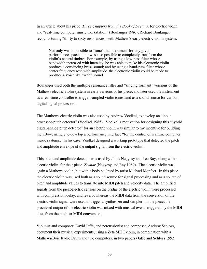
53
In an article about his piece, Three Chapters from the Book of Dreams, for electric violin
and “real-time computer music workstation” (Boulanger 1986), Richard Boulanger
recounts tuning “thirty to sixty resonances” with Mathew’s early electric violin system.
Not only was it possible to “tune” the instrument for any givenperformance space, but it was also possible to completely transform theviolin’s natural timbre. For example, by using a low-pass filter whosebandwidth increased with intensity, he was able to make his electronic violinproduce a convincing brass sound; and by using a band-pass filter whosecenter frequency rose with amplitude, the electronic violin could be made toproduce a voicelike “wah” sound.
Boulanger used both the multiple resonance filter and “singing formant” versions of the
Mathews electric violin system in early versions of his piece, and later used the instrument
as a real-time controller to trigger sampled violin tones, and as a sound source for various
digital signal processors.
The Matthews electric violin was also used by Andrew Voelkel, to develop an “input
processor-pitch detector” (Voelkel 1985). Voelkel’s motivation for designing this “hybrid
digital-analog pitch detector” for an electric violin was similar to my incentive for building
the vBow, namely to develop a performance interface “for the control of realtime computer
music systems.” In his case, Voelkel designed a working prototype that detected the pitch
and amplitude envelope of the output signal from the electric violin.
This pitch and amplitude detector was used by János Négyesy and Lee Ray, along with an
electric violin, for their piece, Zivatar (Négyesy and Ray 1989). The electric violin was
again a Mathews violin, but with a body sculpted by artist Michael Monfort. In this piece,
the electric violin was used both as a sound source for signal processing and as a source of
pitch and amplitude values to translate into MIDI pitch and velocity data. The amplified
signals from the piezoelectric sensors on the bridge of the electric violin were processed
with compression, delay, and reverb, whereas the MIDI data from the conversion of the
electric violin signal were used to trigger a synthesizer and sampler. In the piece, the
processed output of the electric violin was mixed with musical events triggered by the MIDI
data, from the pitch-to-MIDI conversion.
Violinist and composer, David Jaffe, and percussionist and composer, Andrew Schloss,
document their musical experiments, using a Zeta MIDI violin, in combination with a
Mathews/Boie Radio Drum and two computers, in two papers (Jaffe and Schloss 1992,

54
1994). In their piece, Wildlife, the MIDI output of the violin system is used by the
computer to “double the violin part with some synthetic sound” , as well as “make
decisions based on what the violinist is playing.” Some of these musical decisions,
determined by the output of the MIDI violin, include the pitches used for the
percussionist’s improvisation and those used for the melodic material generated by the
computer. Similarly, in the piece, a note from the MIDI violin can determine the root of an
arpeggio performed by the percussionist or the chord played by the computer.
Composer, Daniel Weymouth has composed two virtuosic pieces for MIDI violin and
interactive electronics. This Time, This and Another Violin both use the MIDI pitch and
velocity data from the electric violin to trigger musical events generated by patches
programmed in Max software. These computer-generated musical events are then
transmitted as MIDI data to a synthesizer. In the case of This Time, This the computer
generates musical material that both closely imitates the music performed by the violinist,
and accompanies the performer with contrasting material, shaped by MIDI pitch bend
messages. During Another Violin, the MIDI violin triggers computer-generated musical
events with changes in dynamic, and in the case of a semi-improvised section, groups of
three pitches.
An interesting recent development in the field of violin controllers has come from composer
and violinist Daniel Truman, and engineer Perry Cook. In his dissertation, Reinventing the
Violin (Trueman 1999), Truman describes the component parts of his violin controller: the
R-Bow, a sensor bow that tracks bow force and acceleration, the Fangerbored, the
combination of a linear position sensor, four force-sensing resistors, and a biaxial
accelerometer, the Bonge, an array of bowed foam-covered wood pieces that move against
force-sensing resistors, and a “12-channel spherical speaker array.” The Fangerbored
tracks left-hand and right-hand fingering and overall motion, while the Bonge is used to
sense bowing direction and what string is played. The speaker array, an extension of
Truman and Cook’s NBody project, spatializes input audio, filtered through twelve
frequency responses. When all of the parts are assembled, they comprise the BoSSA, or
Bowed-Sensor-Speaker-Array, providing the player with “fourteen data points,” to be used
as parameters for synthesis and interactive compositions.

55
Bows
Rather than amplifying the vibration of the violin string, or translating its signal into MIDI
data, several researchers, like Truman and Cook, have designed controllers that sense the
bowing gestures that produce the dynamic and timbral expression of the violin. These
violin bow controllers sample bow pressure, acceleration, and proximity to the bridge, with
sensors, using the data as parameters for sound synthesis.
An early precursor to the violin bow controller is described in a paper by Chandrasekhara
Venkata Raman, a founding fellow of the Indian Academy of Sciences, entitled
“Experiments with Mechanically-Played Violins” (Raman 1920-21). In his article, Raman
details the design of a “mechanical player” that permitted “accurate measurements of the
pressure and speed of bowing” and allowed for “the discrimination by ear of the effect of
varying these factors.” This device used an ordinary violin and bow, mounted to an
apparatus that moved the violin back and forth, under the bow, with an electric motor.
The violin sat in a wooden cradle, attached to a brass slide, that moved along a cast-iron
track. The impetus from the electric motor was transferred through two belts, to a conical
pulley and driving wheel. The driving wheel, attached to one of two hubs, transferred the
energy to a chain, strung between the two hubs, which moved the violin assembly, back and
forth. The speed of the bowing motion could be controlled with a tachometer, attached to
the electric motor.
The bow was attached to a wooden lathe, that allowed for adjustments to the amount of hair
that touched the string. The pressure of the bow on the string was adjusted with weights,
hung at the end of the wooden lathe, that balanced on an axis. This early bow controller
allowed Raman to experiment with the interactions between variations of bow speed,
pressure, and position, under controlled conditions.
Another mechanical bow was used by Bradley and Stewart, at the Department of Physics of
the University of Western Ontario, for their study of violin frequency response curves, to
compare results with those from bowing the string by hand, and exciting the string with an
electromagnetic driver (Bradley and Stewart 1970). Their bow was constructed from
synthetic bow hair sewn to a cloth belt, that was strung between two pulleys, and driven by a
motor.
56
A research group studying KANSEI or sensory engineering, at Waseda University in
Japan, recently designed a bowing machine, to test how bowing parameters combine to
produce expressive timbres (Shibuya et al. 1996, 1997). Working under the hypothesis that
understanding how humans adapt their motion to sensory input will lead to designing
robots that move more like humans, these scientists studied “task planning” and “motion
planning” in violinists, with the intent of building a robot that can change bow speed, force,
and position, in response to changes in timbre, a subjective and qualitative, or KANSEI,
musical parameter.
A servomotor controlled by a computer was used by the bowing machine, to vary bow
speed, while the bow force and position were adjusted by moving the table that held the
violin that was bowed. Additionally, bow force was measured by strain gauges attached to
the bow hair. Each bowing parameter could be set to three values, and the combinations of
these parameters were judged within six descriptive categories. From these judgments,
models of the necessary combinations of bow speed, force, and position were constructed,
for the production of each category of timbre.
An early bow controller was developed by the research team at the Association pour la
Création et la Recherche sur les Outils d’Expression (ACROE) and the Laboratoire
d’Informatique Fondamentale et d’Intelligence Artificielle (LIFIA), for use with their
CORDIS-ANIMA real-time synthesis system (Florens et al. 1986). This instrument, one
of two designed to allow a performer to interact with physical models, used “vertical force
and transversal velocity sensors” to track the “transverse force exerted on the string” and
the “sliding speed of the bow.” Like the vBow, these sensor readings were used as data
for parameters of a bowed-string physical model, mapping bow force and velocity to a
“simulation of a vibrating string, associated to a bow friction mechanism.”
Chris Chafe, at Stanford University’s CCRMA, developed a sensor bow for use with his
electric cello, the Celletto. This controller, as show on the cover of Volume 14, Number 4,
of the Computer Music Journal, from 1990, used an accelerometer, attached to the screw at
the end of a standard cello bow, to track bow acceleration, and a strain gauge, mounted at the
middle of the stick of the bow, to sense bow force. The conditioned signal from each
sensor was converted to MIDI and used to affect musical parameters in interactive computer
music programming (Chafe 2003).
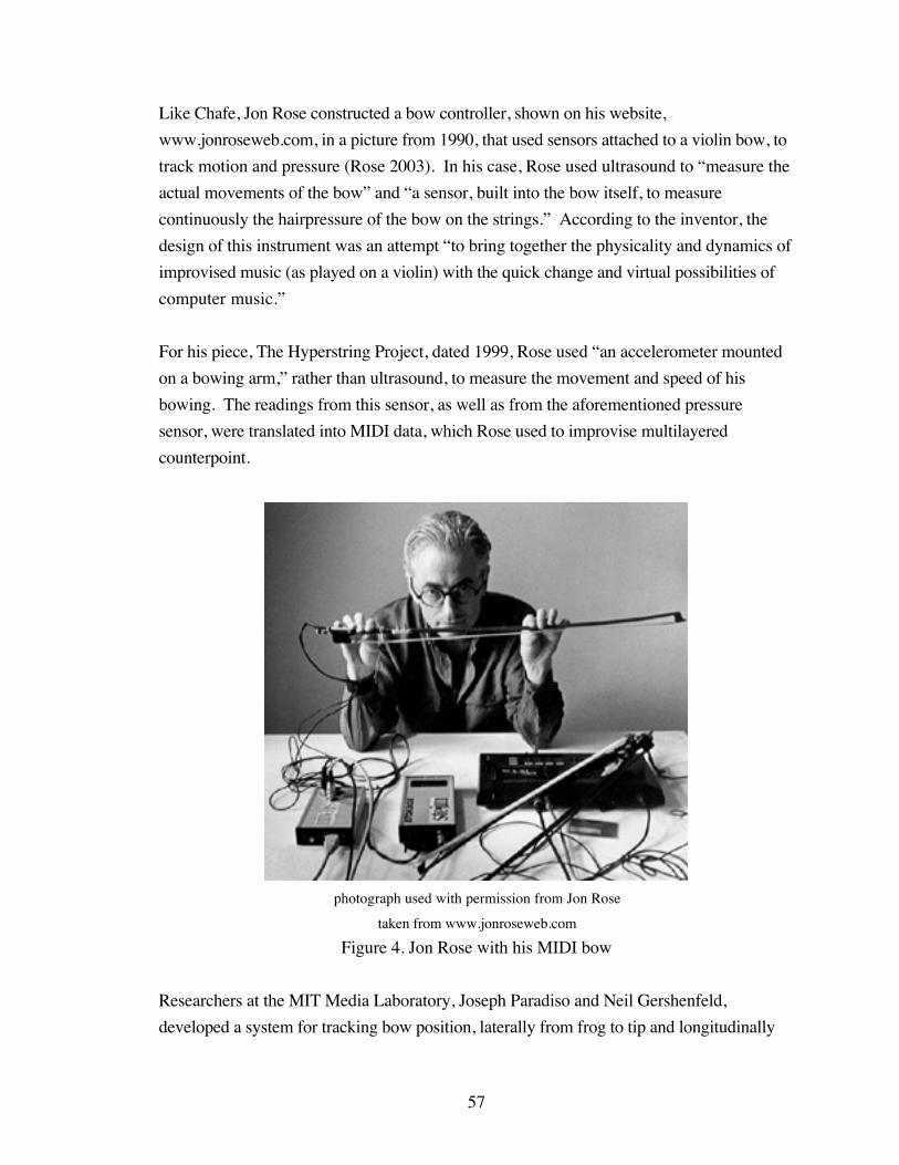
57
Like Chafe, Jon Rose constructed a bow controller, shown on his website,
www.jonroseweb.com, in a picture from 1990, that used sensors attached to a violin bow, to
track motion and pressure (Rose 2003). In his case, Rose used ultrasound to “measure the
actual movements of the bow” and “a sensor, built into the bow itself, to measure
continuously the hairpressure of the bow on the strings.” According to the inventor, the
design of this instrument was an attempt “to bring together the physicality and dynamics of
improvised music (as played on a violin) with the quick change and virtual possibilities of
computer music.”
For his piece, The Hyperstring Project, dated 1999, Rose used “an accelerometer mounted
on a bowing arm,” rather than ultrasound, to measure the movement and speed of his
bowing. The readings from this sensor, as well as from the aforementioned pressure
sensor, were translated into MIDI data, which Rose used to improvise multilayered
counterpoint.
photograph used with permission from Jon Rose
taken from www.jonroseweb.com
Figure 4. Jon Rose with his MIDI bow
Researchers at the MIT Media Laboratory, Joseph Paradiso and Neil Gershenfeld,
developed a system for tracking bow position, laterally from frog to tip and longitudinally
58
relative to the bridge, using electric field sensing (Paradiso and Gershenfeld 1997; Paradiso
1997). The Hypercello version of this system, on which Yo-Yo Ma performed Tod
Machover’s composition, Begin Again Again…, used an antenna, which broadcast a sine
wave from behind the bridge, to a “bow electrode,” comprised of a resistive strip affixed to
a cello bow. The resultant currents, measured at each end of the resistive strip, were used to
calculate lateral and longitudinal position of the bow. Lateral position, relative to the
midpoint of the bow, could be derived from the normalized difference between these two
currents, and longitudinal position of the bow, relative to the bridge antenna, could be
figured from the inverse of the sum of the two currents.
In addition to the electric field sensor, this system used a deformable capacitor, fastened at
the frog of the bow, to track the force applied to the bow by the fingers of the right hand.
Data from this pressure sensor, along with readings from the electric field sensor, and
measurements, from other sensors, of wrist angle and finger position along the strings, were
translated into MIDI commands, and used to control samplers and synthesizers. These
MIDI-translated data streams were also used to control the consol that mixed the output of
the four strings of the RAAD electric cello used, and the signal from a pickup attached to
the top plate of the cello. A Hyperviola version of this system was used by Kim
Kashkashian, for her performance of Machover’s piece, Song of Penance.
A Hyperviolin version of this system was also developed, using the same electric field
sensing technology, for another piece by Machover, Forever and Ever, which Ani Kevaffian
performed with the St. Paul Chamber Orchestra. Because a cordless bow was necessary for
the violin version of this system, the roles of the bow electrode and bridge antenna were
reversed. The resistive strip on the bow was used as the transmitter, while the bridge
antenna was the receiver.
The resistive strip, affixed to a violin bow, transmitted two frequencies, generated by
oscillators connected at either end of the resistive strip. Two voltages, corresponding to the
proportion of these two frequencies received by the bridge antenna, were used to calculate
the lateral and longitudinal position of the bow, using the same formulas as those used for
the Hypercello system.
A piezoresistive strip was used, instead of an elastic capacitor, to sense finger pressure on
the Hyperviolin version of the bow controller. Pressure applied to this piezoresistor created
a voltage, that varied with pressure, which was used to control the frequency of an oscillator.

59
The output of this oscillator was broadcast. from another antenna attached to the bow, to the
bridge antenna. And, variations in the frequency of the signal received from the bow to the
bridge antenna indicated changes in bow pressure.
photograph used with permission from Joseph Paradiso
Figure 5. Joseph Paradiso and Neil Gershenfeld’s Hyperviolin
Diana Young, also working at the MIT Media Lab, has designed another violin bow
controller, in the tradition of the Hyperinstruments developed for the performance of
Machover’s compositions, the Hyperbow (Young 2002). In addition to using the same
electric field sensing technology as the Hyperviolin, to measure bow position, this interface
also uses two two-axis accelerometers, one positioned orthogonal to the other, to track bow
acceleration along three axes, and foil strain gauges, fastened along the length of the bow
stick, to sense downward and lateral forces applied to the bow. These sensor readings were
used to control effects, processing the signal output of the Jensen electric violin used, for
Machover’s recent piece, Toy Symphony.
This violin bow controller was also recently used to test the playability of a bowed-string
physical model (Young and Serafin 2003). For this research, Young, working with Stefania
Serafin, mapped data from the strain gauges of the Hyperbow to the bow force parameter of
the physical model. By changing downward force, while keeping the other parameters
fixed, the researchers were able to produce a tone that “sounded appropriate for the amount
of pressure … applied to the bow.” In addition to changing bow force with a static lateral
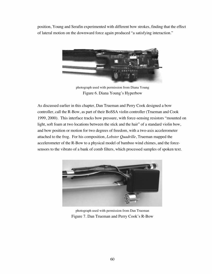
60
position, Young and Serafin experimented with different bow strokes, finding that the effect
of lateral motion on the downward force again produced “a satisfying interaction.”
photograph used with permission from Diana Young
Figure 6. Diana Young’s Hyperbow
As discussed earlier in this chapter, Dan Trueman and Perry Cook designed a bow
controller, call the R-Bow, as part of their BoSSA violin controller (Trueman and Cook
1999, 2000). This interface tracks bow pressure, with force-sensing resistors “mounted on
light, soft foam at two locations between the stick and the hair” of a standard violin bow,
and bow position or motion for two degrees of freedom, with a two-axis accelerometer
attached to the frog. For his composition, Lobster Quadrille, Trueman mapped the
accelerometer of the R-Bow to a physical model of bamboo wind chimes, and the force-
sensors to the vibrato of a bank of comb filters, which processed samples of spoken text.
photograph used with permission from Dan Trueman
Figure 7. Dan Trueman and Perry Cook’s R-Bow
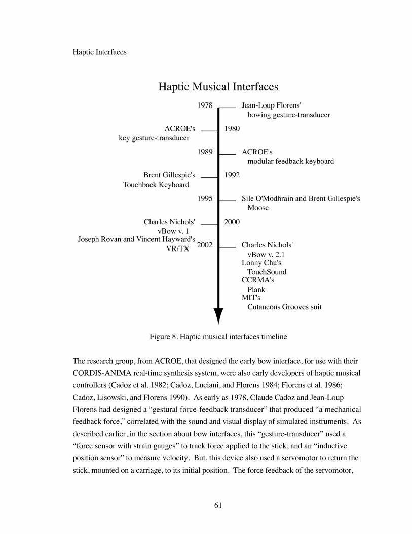
61
Haptic Interfaces
Figure 8. Haptic musical interfaces timeline
The research group, from ACROE, that designed the early bow interface, for use with their
CORDIS-ANIMA real-time synthesis system, were also early developers of haptic musical
controllers (Cadoz et al. 1982; Cadoz, Luciani, and Florens 1984; Florens et al. 1986;
Cadoz, Lisowski, and Florens 1990). As early as 1978, Claude Cadoz and Jean-Loup
Florens had designed a “gestural force-feedback transducer” that produced “a mechanical
feedback force,” correlated with the sound and visual display of simulated instruments. As
described earlier, in the section about bow interfaces, this “gesture-transducer” used a
“force sensor with strain gauges” to track force applied to the stick, and an “inductive
position sensor” to measure velocity. But, this device also used a servomotor to return the
stick, mounted on a carriage, to its initial position. The force feedback of the servomotor,

62
driving the cable system to return the stick, was moderated by electrodynamic clutches,
controlled by a computer responding to the position sensor.
The second force-feedback interface, from the research group at ACROE, illustrated by a
drawing in the paper from 1982, and in photographs in the papers from 1984 and 1990,
consisted of a single haptic key. This gestural transducer contained “a force sensor with
strain gauges, a displacement sensor with inductive effect …, and a torque motor.” The
strain gauges were positioned under the key, which was attached to an arm. Below the arm
and just past the key hung a pivoting connecting rod. A cable, attached at either end of the
connecting rod, wrapped around a rotating pulley, which was attached to a position sensor
on one side, and a motor on the other. As the key was depressed, the strain gauges below
the key read the pressure, and the position sensor read the rotation of the pulley, driven by
the cable attached to the connecting rod, which was pushed downward by the arm that the
key was attached to.
This haptic key, which served as a “force sensor with position-return” or a “position
sensor with force-return,” was used to physically interact with sound synthesis models of
plucked strings and maracas. With the string model, the key was used as a plectrum, to
pluck the two simulated strings, producing a “mechanical feedback” of “the reaction of the
strings to the gestual [sic] action.” For the model of maracas, the key was used to shake
the simulated “resonant cavity” filled with “particles,” generating the haptic feedback of
the inertia of the instrument and “the hit of particles on the surfaces.”
The “modular feedback keyboard,” shown in drawings in the paper from 1990, and in two
photographs on the cover of the Computer Music Journal, Volume 14, Number 2,
represents the third haptic musical interface designed by the group from ACROE. The
caption for these photographs, on the inside cover of the journal, succinctly describes the
configuration of components and a possible use for this haptic keyboard.
The keys are mounted on bars connected to the coils of the so-called slicedmotor, whereby the position can be accurately sensed and a variable forcecan be applied to the key. This allows control programs to produce thearbitrary force-versus-position function on the keys, simulating, for example,the differences among pianos, harpsichords, and clavichords.
This “sliced motor,” a patented device consisting of a “single magnetic polarization
circuit,” along with a position sensor, comprises a single “sensor-motor module,” that has
the thickness of about one piano key. Any number of these sensor-motor modules can be
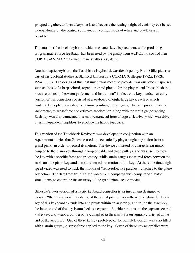
63
grouped together, to form a keyboard, and because the resting height of each key can be set
independently by the control software, any configuration of white and black keys is
possible.
This modular feedback keyboard, which measures key displacement, while producing
programmable force feedback, has been used by the group from ACROE, to control their
CORDIS-ANIMA “real-time music synthesis system.”
Another haptic keyboard, the Touchback Keyboard, was developed by Brent Gillespie, as a
part of his doctoral studies at Stanford University’s CCRMA (Gillespie 1992a, 1992b,
1994, 1996). The design of this instrument was meant to provide “various touch responses,
such as those of a harpsichord, organ, or grand piano” for the player, and “reestablish the
touch relationship between performer and instrument” in electronic keyboards. An early
version of this controller consisted of a keyboard of eight large keys, each of which
contained an optical encoder, to measure position, a strain gauge, to track pressure, and a
tachometer, to sense force and estimate acceleration, along with the strain gauge reading.
Each key was also connected to a motor, extracted from a large disk drive, which was driven
by an independent amplifier, to produce the haptic feedback.
This version of the Touchback Keyboard was developed in conjunction with an
experimental device that Gillespie used to mechanically play a single key action from a
grand piano, in order to record its motion. The device consisted of a large linear motor
coupled to the piano key through a loop of cable and three pulleys, and was used to move
the key with a specific force and trajectory, while strain gauges measured force between the
cable and the piano key, and encoders sensed the motion of the key. At the same time, high-
speed video was used to track the motion of “retro-reflective patches,” attached to the piano
key action. The data from the digitized video were compared with computer-animated
simulations, to determine the accuracy of the grand piano action model.
Gillespie’s later version of a haptic keyboard controller is an instrument designed to
recreate “the mechanical impedance of the grand piano in a synthesizer keyboard.” Each
key of this keyboard extends into and pivots within an assembly, and inside the assembly,
the interior end of the key is attached to a capstan. A cable runs around the capstan secured
to the key, and wraps around a pulley, attached to the shaft of a servomotor, fastened at the
end of the assembly. One of these keys, a prototype of the complete design, was also fitted
with a strain gauge, to sense force applied to the key. Seven of these key assemblies were
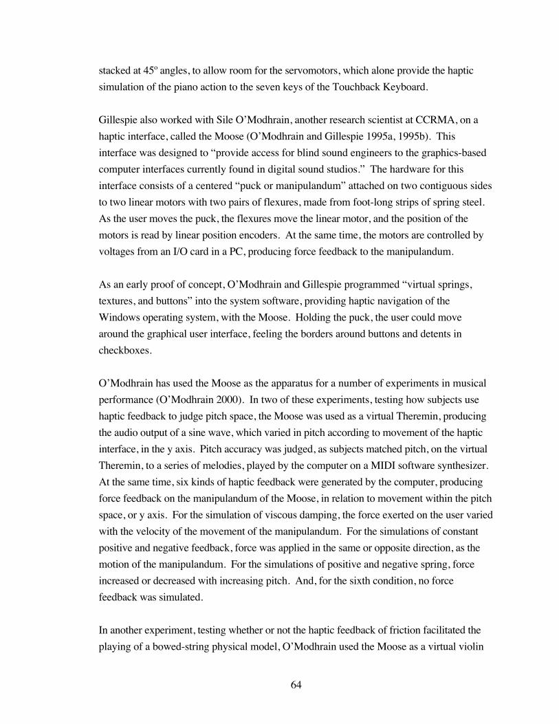
64
stacked at 45º angles, to allow room for the servomotors, which alone provide the haptic
simulation of the piano action to the seven keys of the Touchback Keyboard.
Gillespie also worked with Sile O’Modhrain, another research scientist at CCRMA, on a
haptic interface, called the Moose (O’Modhrain and Gillespie 1995a, 1995b). This
interface was designed to “provide access for blind sound engineers to the graphics-based
computer interfaces currently found in digital sound studios.” The hardware for this
interface consists of a centered “puck or manipulandum” attached on two contiguous sides
to two linear motors with two pairs of flexures, made from foot-long strips of spring steel.
As the user moves the puck, the flexures move the linear motor, and the position of the
motors is read by linear position encoders. At the same time, the motors are controlled by
voltages from an I/O card in a PC, producing force feedback to the manipulandum.
As an early proof of concept, O’Modhrain and Gillespie programmed “virtual springs,
textures, and buttons” into the system software, providing haptic navigation of the
Windows operating system, with the Moose. Holding the puck, the user could move
around the graphical user interface, feeling the borders around buttons and detents in
checkboxes.
O’Modhrain has used the Moose as the apparatus for a number of experiments in musical
performance (O’Modhrain 2000). In two of these experiments, testing how subjects use
haptic feedback to judge pitch space, the Moose was used as a virtual Theremin, producing
the audio output of a sine wave, which varied in pitch according to movement of the haptic
interface, in the y axis. Pitch accuracy was judged, as subjects matched pitch, on the virtual
Theremin, to a series of melodies, played by the computer on a MIDI software synthesizer.
At the same time, six kinds of haptic feedback were generated by the computer, producing
force feedback on the manipulandum of the Moose, in relation to movement within the pitch
space, or y axis. For the simulation of viscous damping, the force exerted on the user varied
with the velocity of the movement of the manipulandum. For the simulations of constant
positive and negative feedback, force was applied in the same or opposite direction, as the
motion of the manipulandum. For the simulations of positive and negative spring, force
increased or decreased with increasing pitch. And, for the sixth condition, no force
feedback was simulated.
In another experiment, testing whether or not the haptic feedback of friction facilitated the
playing of a bowed-string physical model, O’Modhrain used the Moose as a virtual violin
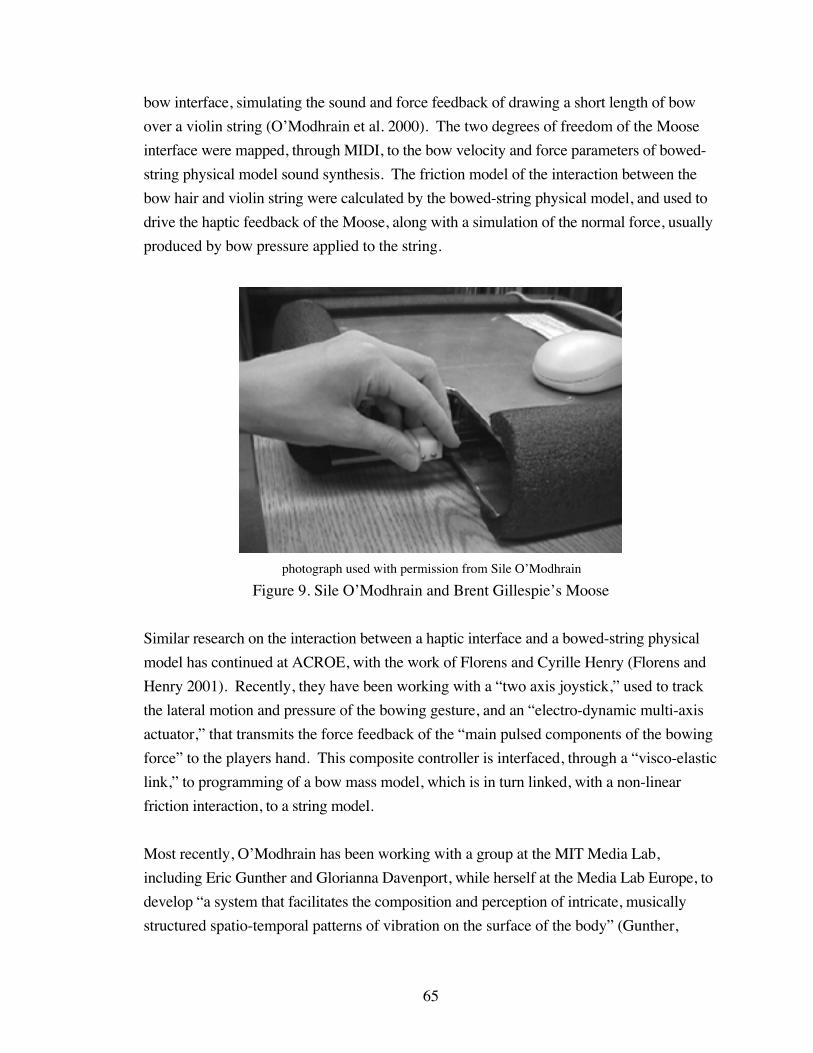
65
bow interface, simulating the sound and force feedback of drawing a short length of bow
over a violin string (O’Modhrain et al. 2000). The two degrees of freedom of the Moose
interface were mapped, through MIDI, to the bow velocity and force parameters of bowed-
string physical model sound synthesis. The friction model of the interaction between the
bow hair and violin string were calculated by the bowed-string physical model, and used to
drive the haptic feedback of the Moose, along with a simulation of the normal force, usually
produced by bow pressure applied to the string.
photograph used with permission from Sile O’Modhrain
Figure 9. Sile O’Modhrain and Brent Gillespie’s Moose
Similar research on the interaction between a haptic interface and a bowed-string physical
model has continued at ACROE, with the work of Florens and Cyrille Henry (Florens and
Henry 2001). Recently, they have been working with a “two axis joystick,” used to track
the lateral motion and pressure of the bowing gesture, and an “electro-dynamic multi-axis
actuator,” that transmits the force feedback of the “main pulsed components of the bowing
force” to the players hand. This composite controller is interfaced, through a “visco-elastic
link,” to programming of a bow mass model, which is in turn linked, with a non-linear
friction interaction, to a string model.
Most recently, O’Modhrain has been working with a group at the MIT Media Lab,
including Eric Gunther and Glorianna Davenport, while herself at the Media Lab Europe, to
develop “a system that facilitates the composition and perception of intricate, musically
structured spatio-temporal patterns of vibration on the surface of the body” (Gunther,
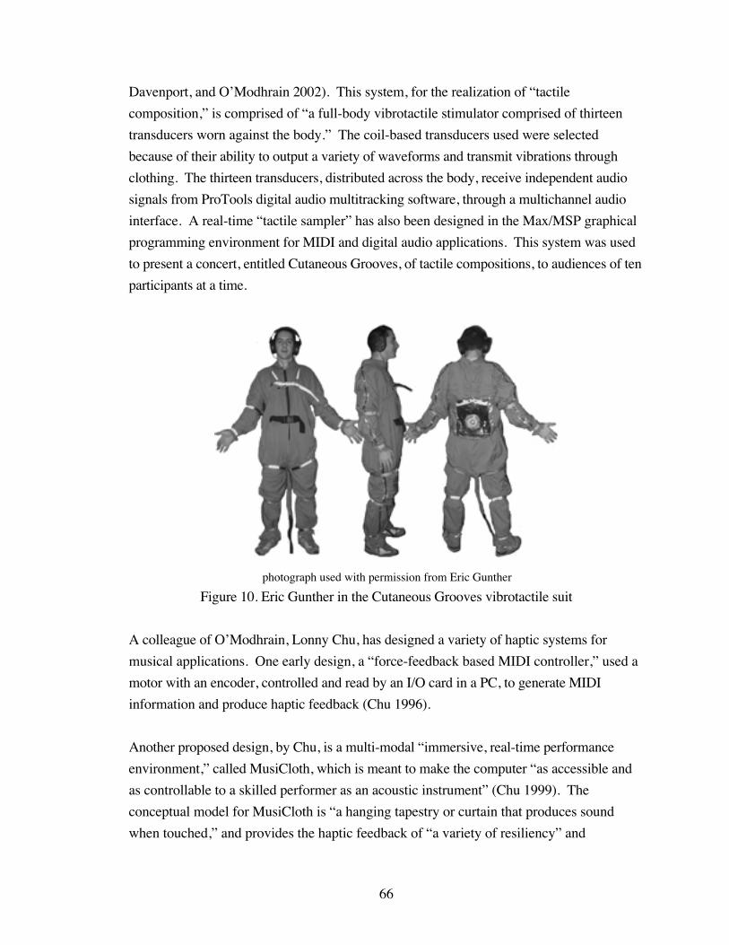
66
Davenport, and O’Modhrain 2002). This system, for the realization of “tactile
composition,” is comprised of “a full-body vibrotactile stimulator comprised of thirteen
transducers worn against the body.” The coil-based transducers used were selected
because of their ability to output a variety of waveforms and transmit vibrations through
clothing. The thirteen transducers, distributed across the body, receive independent audio
signals from ProTools digital audio multitracking software, through a multichannel audio
interface. A real-time “tactile sampler” has also been designed in the Max/MSP graphical
programming environment for MIDI and digital audio applications. This system was used
to present a concert, entitled Cutaneous Grooves, of tactile compositions, to audiences of ten
participants at a time.
photograph used with permission from Eric Gunther
Figure 10. Eric Gunther in the Cutaneous Grooves vibrotactile suit
A colleague of O’Modhrain, Lonny Chu, has designed a variety of haptic systems for
musical applications. One early design, a “force-feedback based MIDI controller,” used a
motor with an encoder, controlled and read by an I/O card in a PC, to generate MIDI
information and produce haptic feedback (Chu 1996).
Another proposed design, by Chu, is a multi-modal “immersive, real-time performance
environment,” called MusiCloth, which is meant to make the computer “as accessible and
as controllable to a skilled performer as an acoustic instrument” (Chu 1999). The
conceptual model for MusiCloth is “a hanging tapestry or curtain that produces sound
when touched,” and provides the haptic feedback of “a variety of resiliency” and
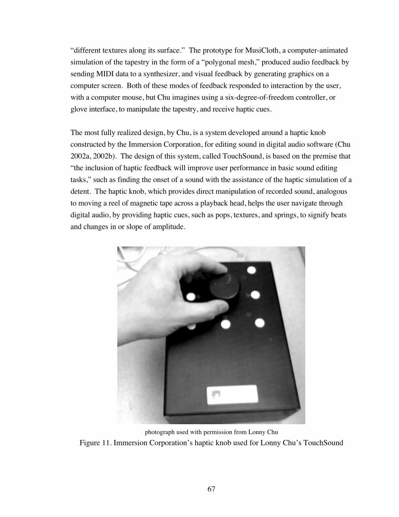
67
“different textures along its surface.” The prototype for MusiCloth, a computer-animated
simulation of the tapestry in the form of a “polygonal mesh,” produced audio feedback by
sending MIDI data to a synthesizer, and visual feedback by generating graphics on a
computer screen. Both of these modes of feedback responded to interaction by the user,
with a computer mouse, but Chu imagines using a six-degree-of-freedom controller, or
glove interface, to manipulate the tapestry, and receive haptic cues.
The most fully realized design, by Chu, is a system developed around a haptic knob
constructed by the Immersion Corporation, for editing sound in digital audio software (Chu
2002a, 2002b). The design of this system, called TouchSound, is based on the premise that
“the inclusion of haptic feedback will improve user performance in basic sound editing
tasks,” such as finding the onset of a sound with the assistance of the haptic simulation of a
detent. The haptic knob, which provides direct manipulation of recorded sound, analogous
to moving a reel of magnetic tape across a playback head, helps the user navigate through
digital audio, by providing haptic cues, such as pops, textures, and springs, to signify beats
and changes in or slope of amplitude.
photograph used with permission from Lonny Chu
Figure 11. Immersion Corporation’s haptic knob used for Lonny Chu’s TouchSound
68
Other researchers have suggested designs for, or built prototypes of, additional haptic
musical controllers. Bert Bongers, at the Royal Conservatory in the Netherlands, has
proposed a haptic glove interface, that uses Muscle Wire, a proprietary material that
“shortens in length when electricity is supplied,” to provide resistance to flexing fingers,
and Tactors, plates that “transform an electric signal into a haptic cue,” to supply force
feedback to fingertips, in relation to the music generated by this controller (Bongers 1994).
Another haptic musical controller system, the VR/TX, designed by Joseph Rovan and
Vincent Hayward, in collaboration with percussionist Mark Goldstein, began as “an attempt
to incorporate feedback into a custom glove controller” (Rovan and Hayward 2000). Three
versions of a coil and magnet transducer were constructed, one ring-mounted, another
mounted to the glove controller, and the other “embedded in a surface on which a performer
can stand.” These transducers were driven by audio signals, or “tactile sounds,” generated
by programming in Max/MSP software, which responded to the output from a Dimension
Beam infrared controller, adding tactile feedback to an open-air performance interface.
A team at CCRMA, including Bill Verplank, Michael Gurevich, and Max Mathews, have
designed the prototype of a haptic interface, called The Plank, which provides “one axis of
force-feedback with limited range of motion” (Verplank, Gurevich, and Mathews 2002).
This controller, made from the voice-coil motor of an old computer disk drive, has been
used to experiment with haptic effects, such as simulating the slope of a terrain with positive
and negative forces, and will be used to interact with “scanned synthesis,” by directly
manipulating the shape of an audio waveform.
Like these violin and bow controllers, the vBow has been constructed to transduce the
bowing gesture of a violinist into sound synthesis parameters, by tracking the lateral,
rotational, vertical, and longitudinal motion of a bow stroke with encoder sensors. And, like
these haptic musical interfaces, the vBow was built to provide the performer with tactile-
kinesthetic feedback, by simulating vibration, friction, detents, elasticity, and barriers with
servomotor and cable systems. What is unique to the vBow is its ability to simultaneously
simulate four independent haptic cues, mapped to four diverse yet interdependent bowing
motions, with a four degree of freedom human-computer interface, built specifically to meet
the performance needs of a violinist.

69
CHAPTER 4
VBOW HARDWARE
Construction
Figure 12. Construction synopsis
Version 1
The first version of the vBow was designed around a single servomotor with digital encoder
and cable system, which sensed one degree of freedom of the bowing gesture of a violinist,
and provided the haptic feedback of a randomly varied vibration (Nichols 2000).
Figure 13. The vBow, version 1

70
The servomotor, a Maxon Precision Motors RE Ø25 series servomotor, was selected for its
stall torque and operating range, so it would withstand the force of a normal bow stroke
(Askenfelt 1989), while providing haptic feedback. At the back of the servomotor is
attached a digital encoder that reads one thousand transitions per revolution from five
hundred slots in two channels, providing a resolution of two thousand counts per revolution.
The single servomotor was attached to an acrylic housing with two screws that fit through
holes drilled through the depth of the housing, and screwed into threaded holes in the front
base of the cylinder of the servomotor.
An aluminum capstan, attached to the shaft of the servomotor with a set screw, fit through a
third, larger hole, drilled through the depth of the acrylic housing. The capstan was turned
on a lathe from an aluminum rod, to the diameter of the hole in the housing, and was further
machined with a groove for the cable, and a threaded hole for the set screw.
Figure 14. Servomotor with encoder and capstan
Also attached to the housing was a linear bearing through which the stick of the vBow
passed. The linear bearing was secured to the housing with a strip of metal that wrapped
over the top of the bearing, and was fastened to the housing with a screw and nut. The
screw passed through a hole at one end of the metal strip, through a fourth hole drilled
through the depth of the housing, and through another hole at the other end of the metal
strip, and was terminated with a nut. A strip of craft foam, attached to the inside arc of the
metal strip, helped hold the linear bearing tightly against the housing.
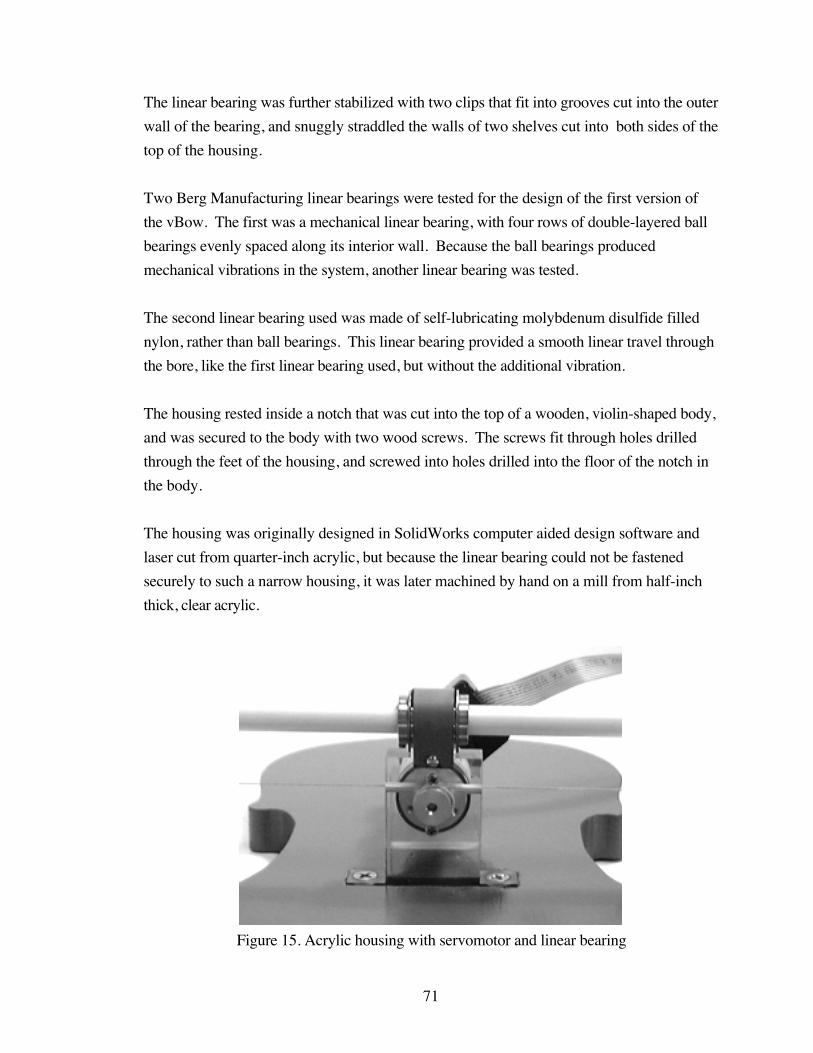
71
The linear bearing was further stabilized with two clips that fit into grooves cut into the outer
wall of the bearing, and snuggly straddled the walls of two shelves cut into both sides of the
top of the housing.
Two Berg Manufacturing linear bearings were tested for the design of the first version of
the vBow. The first was a mechanical linear bearing, with four rows of double-layered ball
bearings evenly spaced along its interior wall. Because the ball bearings produced
mechanical vibrations in the system, another linear bearing was tested.
The second linear bearing used was made of self-lubricating molybdenum disulfide filled
nylon, rather than ball bearings. This linear bearing provided a smooth linear travel through
the bore, like the first linear bearing used, but without the additional vibration.
The housing rested inside a notch that was cut into the top of a wooden, violin-shaped body,
and was secured to the body with two wood screws. The screws fit through holes drilled
through the feet of the housing, and screwed into holes drilled into the floor of the notch in
the body.
The housing was originally designed in SolidWorks computer aided design software and
laser cut from quarter-inch acrylic, but because the linear bearing could not be fastened
securely to such a narrow housing, it was later machined by hand on a mill from half-inch
thick, clear acrylic.
Figure 15. Acrylic housing with servomotor and linear bearing
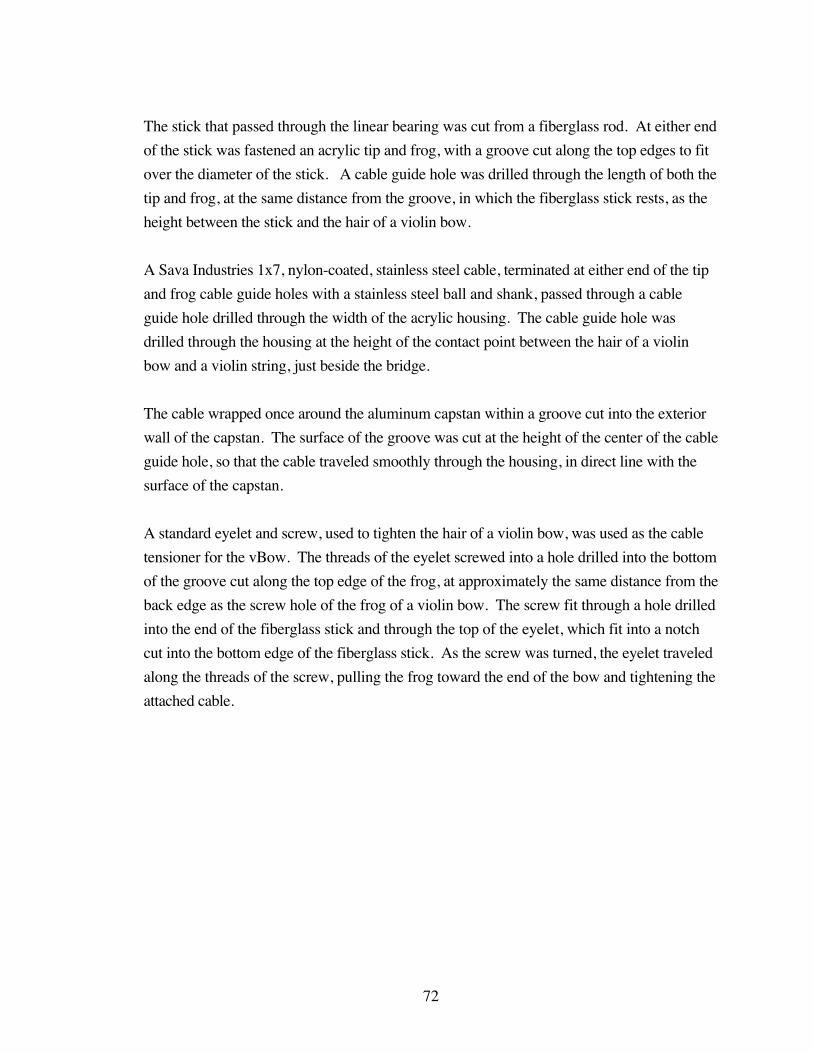
72
The stick that passed through the linear bearing was cut from a fiberglass rod. At either end
of the stick was fastened an acrylic tip and frog, with a groove cut along the top edges to fit
over the diameter of the stick. A cable guide hole was drilled through the length of both the
tip and frog, at the same distance from the groove, in which the fiberglass stick rests, as the
height between the stick and the hair of a violin bow.
A Sava Industries 1x7, nylon-coated, stainless steel cable, terminated at either end of the tip
and frog cable guide holes with a stainless steel ball and shank, passed through a cable
guide hole drilled through the width of the acrylic housing. The cable guide hole was
drilled through the housing at the height of the contact point between the hair of a violin
bow and a violin string, just beside the bridge.
The cable wrapped once around the aluminum capstan within a groove cut into the exterior
wall of the capstan. The surface of the groove was cut at the height of the center of the cable
guide hole, so that the cable traveled smoothly through the housing, in direct line with the
surface of the capstan.
A standard eyelet and screw, used to tighten the hair of a violin bow, was used as the cable
tensioner for the vBow. The threads of the eyelet screwed into a hole drilled into the bottom
of the groove cut along the top edge of the frog, at approximately the same distance from the
back edge as the screw hole of the frog of a violin bow. The screw fit through a hole drilled
into the end of the fiberglass stick and through the top of the eyelet, which fit into a notch
cut into the bottom edge of the fiberglass stick. As the screw was turned, the eyelet traveled
along the threads of the screw, pulling the frog toward the end of the bow and tightening the
attached cable.
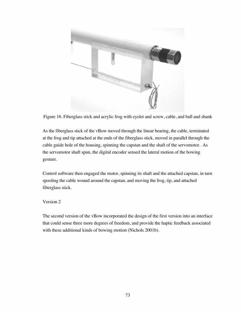
73
Figure 16. Fiberglass stick and acrylic frog with eyelet and screw, cable, and ball and shank
As the fiberglass stick of the vBow moved through the linear bearing, the cable, terminated
at the frog and tip attached at the ends of the fiberglass stick, moved in parallel through the
cable guide hole of the housing, spinning the capstan and the shaft of the servomotor. As
the servomotor shaft spun, the digital encoder sensed the lateral motion of the bowing
gesture.
Control software then engaged the motor, spinning its shaft and the attached capstan, in turn
spooling the cable wound around the capstan, and moving the frog, tip, and attached
fiberglass stick.
Version 2
The second version of the vBow incorporated the design of the first version into an interface
that could sense three more degrees of freedom, and provide the haptic feedback associated
with these additional kinds of bowing motion (Nichols 2001b).

74
Figure 17. The vBow, version 2
Because the laser used at the time could not cut half-inch thick acrylic, the pieces for this
second version were laser cut in duplicate from quarter-inch thick acrylic, and the duplicate
pieces glued together with acrylic epoxy, to make half-inch thick pieces.
The pieces were then fastened at the joints with stainless steel pins, which were secured with
e-clips that fit into grooves cut into their circumference.
Version 2.1
Improvements were made to the design of the second version of the vBow, in order to
improve the mechanical stability of the interface. Specifically, the arm was shortened,
moving the base to the edge of the top arc of the violin body, allowing for the fingerboard to
be shortened, and the pieces were joined with threaded stainless steel pins and lock nuts
(Nichols 2002).
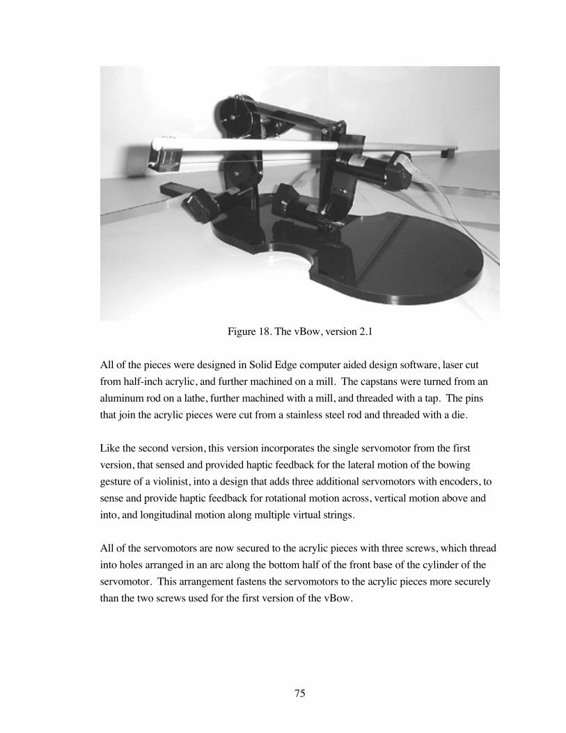
75
Figure 18. The vBow, version 2.1
All of the pieces were designed in Solid Edge computer aided design software, laser cut
from half-inch acrylic, and further machined on a mill. The capstans were turned from an
aluminum rod on a lathe, further machined with a mill, and threaded with a tap. The pins
that join the acrylic pieces were cut from a stainless steel rod and threaded with a die.
Like the second version, this version incorporates the single servomotor from the first
version, that sensed and provided haptic feedback for the lateral motion of the bowing
gesture of a violinist, into a design that adds three additional servomotors with encoders, to
sense and provide haptic feedback for rotational motion across, vertical motion above and
into, and longitudinal motion along multiple virtual strings.
All of the servomotors are now secured to the acrylic pieces with three screws, which thread
into holes arranged in an arc along the bottom half of the front base of the cylinder of the
servomotor. This arrangement fastens the servomotors to the acrylic pieces more securely
than the two screws used for the first version of the vBow.

76
In this design, the housing from the first version of the vBow is suspended above an acrylic
violin-shaped body on an articulated arm. To each piece of the articulated arm is secured a
servomotor or cable for each of the additional degrees of freedom of the interface.
Figure 19. Degrees of freedom
The fiberglass stick from the first version is also used in this version, with a new tip and
frog attached at either end. Like the first version, a cable guide hole is drilled through the
length of the tip and frog, the tip is secured to the fiberglass stick with two screws, and the
frog is attached with an eyelet and screw.
The housing from the first version has been modified, with a hole drilled through the width,
at the diameter of the fiberglass stick, to replace the linear bearing of the first version.
When the fiberglass stick is oiled, it passes smoothly through this hole, with little additional
friction added to the system.
Like the first version, the fiberglass stick passes through the hole drilled through the
housing piece, pulling the cable that is terminated at the ends of the tip and frog pieces. The
cable, which is wrapped around the capstan, spins the shaft of the servomotor, which is

77
secured to the housing piece. As the servomotor shaft spins, the digital encoder reads the
shaft rotation, sensing lateral position, and sends the data through a ribbon cable to a
connector on a circuit board.
Additionally, the housing piece has been redesigned to pivot against the rotation piece. The
bottom edge of the housing piece is cut at a curve that is the inverse of the arc of a violin
bridge. The housing piece is fastened to the rotation piece with a threaded pin and two lock
nuts, that fit through holes drilled through the depth of both the housing and rotation piece.
The hole in the housing piece is drilled at a point equidistant from the point of contact
between the cable and the capstan for the first lateral degree of freedom, and the curved
bottom edge of the housing piece. The result of this position for the pivot point, and the arc
of the curved bottom edge, is that the vBow pivots in the same arc as a violin bow crossing
violin strings.
Below the curved edge of the housing piece is a capstan attached to the shaft of the
servomotor for the second rotational degree of freedom. This servomotor with encoder,
which senses and provides haptic feedback for the motion of a violin bow crossing the
strings of a violin, is secured to the bottom of the rotation piece with three screws that fit
through holes drilled through its depth. The capstan fits through a fourth hole drilled
through the depth of the rotation piece, and extends beyond the depth of the housing piece
above.
Two screws tighten into threaded holes drilled and tapped into the bottom edge of the
housing piece, at either end of the curve. A cable extends along the bottom curved edge,
clamped tightly to the housing piece by the screws, and wraps around the capstan below.
As the housing piece pivots against the rotation piece, the curved edge rides along the
capstan below, and the attached cable spins the capstan and the servomotor shaft. Like the
servomotor with encoder of the first lateral degree of freedom, the encoder reads the shaft
rotation, sensing rotational position, and sends the data through the ribbon cable to the
connector on the circuit board.

78
Figure 20. Rotational motion
The rotation piece is joined to an acrylic arm piece, with a threaded pin and two lock nuts.
The far end of the arm piece fits into a slot, cut into the middle of the top edge of the
rotation piece, to a depth that allows the rotation piece to swivel back and forth, without
colliding with the arm piece.
The arm piece is joined at its other end to the longitude piece, with another threaded pin and
two lock nuts. A cable wraps around the outer edge of this circular-shaped base of the arm
piece, passing through a cable guide hole drilled through its height, at the point where the
extension and circular-shaped base of the arm piece meet.
The cable is terminated at the top of the cable guide hole with a stainless steel ball and
shank, and secured to the edge of the circular-shaped base, with a screw that tightens into a
threaded hole drilled into the top edge of the arm piece. This cable wraps around the
capstan attached to the servomotor and encoder that senses and provides haptic feedback for
vertical motion of a violin bow lifting above and pushing into the strings of a violin.
This servomotor for the third vertical degree of freedom is secured to the longitude piece,
with three screws that fit through holes drilled through the depth of the longitude piece. The
capstan for this servomotor extends through a fourth hole drilled through the depth of the
longitude piece, and extends past the depth of the circular-shaped base of the arm piece
above.
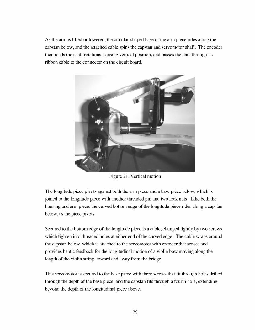
79
As the arm is lifted or lowered, the circular-shaped base of the arm piece rides along the
capstan below, and the attached cable spins the capstan and servomotor shaft. The encoder
then reads the shaft rotations, sensing vertical position, and passes the data through its
ribbon cable to the connector on the circuit board.
Figure 21. Vertical motion
The longitude piece pivots against both the arm piece and a base piece below, which is
joined to the longitude piece with another threaded pin and two lock nuts. Like both the
housing and arm piece, the curved bottom edge of the longitude piece rides along a capstan
below, as the piece pivots.
Secured to the bottom edge of the longitude piece is a cable, clamped tightly by two screws,
which tighten into threaded holes at either end of the curved edge. The cable wraps around
the capstan below, which is attached to the servomotor with encoder that senses and
provides haptic feedback for the longitudinal motion of a violin bow moving along the
length of the violin string, toward and away from the bridge.
This servomotor is secured to the base piece with three screws that fit through holes drilled
through the depth of the base piece, and the capstan fits through a fourth hole, extending
beyond the depth of the longitudinal piece above.

80
As the longitude piece pivots, the cable fastened to its curved bottom edge spins the capstan
attached to the shaft of the servomotor for the fourth longitudinal degree of freedom. The
encoder at the back of the servomotor reads the shaft rotations, and senses the longitudinal
position of the articulated arm, sending the data through its ribbon cable to the connector on
the circuit board.
Figure 22. Longitudinal motion
The base piece is secured to a violin-shaped body piece, with two screws that pass through
holes drilled through the height of the body piece, and tighten into threaded holes drilled up
through the bottom edge, into the height of the base piece. The violin-shaped body piece
provides a stable foundation for the vBow.
Version 2.2
At the suggestion of Kenneth Salisbury, two improvements have been made to the design of
the vBow hardware, to counterbalance the load on the arm piece with a counterweight, and to
mechanically stabilize the longitude piece with a spring.
The new arm piece, which now extends in both directions, was designed and laser cut from
acrylic. This arm piece fastens to the longitude piece, like the old arm piece, with the same
threaded pin and lock nuts, and again rides over the capstan attached to the motor fastened
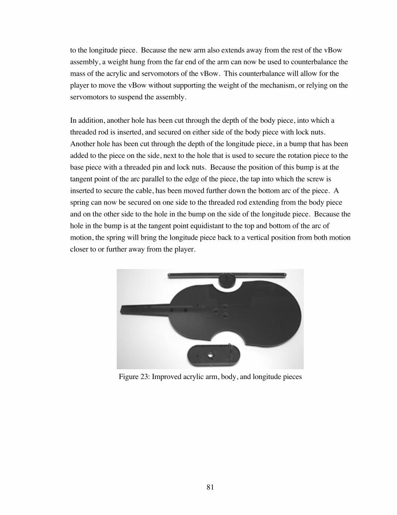
81
to the longitude piece. Because the new arm also extends away from the rest of the vBow
assembly, a weight hung from the far end of the arm can now be used to counterbalance the
mass of the acrylic and servomotors of the vBow. This counterbalance will allow for the
player to move the vBow without supporting the weight of the mechanism, or relying on the
servomotors to suspend the assembly.
In addition, another hole has been cut through the depth of the body piece, into which a
threaded rod is inserted, and secured on either side of the body piece with lock nuts.
Another hole has been cut through the depth of the longitude piece, in a bump that has been
added to the piece on the side, next to the hole that is used to secure the rotation piece to the
base piece with a threaded pin and lock nuts. Because the position of this bump is at the
tangent point of the arc parallel to the edge of the piece, the tap into which the screw is
inserted to secure the cable, has been moved further down the bottom arc of the piece. A
spring can now be secured on one side to the threaded rod extending from the body piece
and on the other side to the hole in the bump on the side of the longitude piece. Because the
hole in the bump is at the tangent point equidistant to the top and bottom of the arc of
motion, the spring will bring the longitude piece back to a vertical position from both motion
closer to or further away from the player.
Figure 23: Improved acrylic arm, body, and longitude pieces
82
Electronics
Version 1
The electronics for the first version of the vBow were comprised of a Maxon Precision
Motors linear servo amplifier, linear DC power supply, breakout board, servomotor disable
switch, and power switch.
The servo amplifier was selected for its output power and voltage, and the power supply for
its voltage output under load and current ripple.
The 10-contact socket connector at the end of the ribbon cable from the encoder, the 50-
contact socket at the end of the ribbon cable plugged into the connector on the servo control
and data acquisition card, and the connectors at the end of the wires soldered to the leads of
the servomotor and secured by screws to the servo amplifier terminal block, plugged into the
block and post headers on the breakout board. Under the breakout board, wires were
soldered to the pins of the block and post headers, connecting the output and input from the
encoder, servo control and data acquisition card, servomotors, and servo amplifier.
A Servo To Go servomotor and encoder I/O card, installed in a Pentium III computer, was
used to read the three channels of encoder output and send control voltage for the
servomotor to the servo amplifier. The card also supplied voltage to the encoder, and
grounding for the servo amplifier and encoder.
The AC input to the power supply was connected to a switch, as was the output current from
the servo amplifier to the servomotor. In the event of a problem with the control software,
the disable switch could be used to cut the current sent from the servo control card, through
the servo amplifier, to the servomotor.

83
Figure 24. Electronics for the vBow, version 1
Version 2
The electronics for the current version of the vBow consist of four Advanced Motion
Controls servo amplifiers and filter cards, a breakout board, two 4-pole servomotor disable
switches, a power switch, and a power supply.
The servo amplifiers were selected for their output current and supply voltage range. The
filter cards were necessary to increase the load inductance of the servomotors to match the
output current from the servo amplifiers. The power supply was chosen for its output
voltage and nominal output current.
Like the electronics for the first version of the vBow, the two servomotor disable switches
cut the current from the servo amplifiers to the four servomotors, in the event of a problem
with the control software. The power switch turns on and off the current from the power
supply to the servo amplifiers.
The breakout board is assembled from a circuit board, one 50-contact and four 10-contact
box headers, and two 8-position terminal blocks. The circuit board was designed in
84
Osmond printed circuit board design software, and manufactured by Alberta Printed
Circuits.
The pins of the box headers and terminal blocks fit into holes drilled through the circuit
board, and are soldered to the pads at the ends of the traces on the circuit board. The traces
on the circuit board connect the pins of the box headers and terminal blocks, routing the
input and output from the servo control and data acquisition card to the encoders and servo
amplifiers.
The connectors at the ends of the 10-conductor ribbon cables attached to the encoders and
the 50- conductor ribbon cable plugged into the servo control and data acquisition card plug
into the box headers on the circuit board. The leads from the terminal blocks of the servo
amplifiers are secured to the first terminal block on the circuit board. The second terminal
bock serves as a junction at which the wires soldered to the leads of the servomotors and the
wires from the servomotor disable switches are clamped together.
The servo amplifiers, filter cards, breakout board, and switches are mounted to four clear
acrylic shelves, with screws and nuts, and are raised above the surface of the shelves by
spacers, for ventilation and cooling. The shelves, separated by spacers, are stacked on four
threaded rods, and secured with lock nuts at the top. The threaded rods pass through holes
drilled through the thickness of the acrylic, in the four corners of the shelves, through the
spacers, and are screwed to the base of the Advanced Motion Controls power supply,
securing the assembly of electronics and shelves to the power supply.
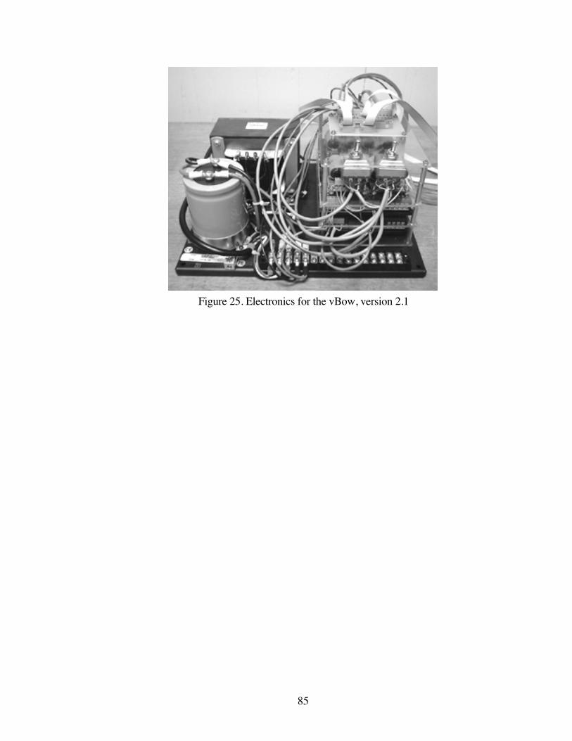
85
Figure 25. Electronics for the vBow, version 2.1
86
CHAPTER 5
VBOW SOFTWARE
Because the bowed-string physical model, used for sound synthesis in the vBow software,
has been reverse-engineered from the interaction between the violin bow and string, it is
important, when studying the developmental history of the physical model, to understand
tone production from the perspective of the violinist. And, since the motivation behind the
development of the bowed-string physical model is not only to produce a realistic sound,
but also an expressively dynamic violin tone, through computer programming, it is valuable
to learn how violinists control changes in the volume and timbre of the tone.
Many treatises by violin instructors outline the proper technique needed to produce a
musically appropriate tone when bowing on a violin string, and in each explanation it is
implicit that the expressive character of the violin relies on this interaction. Each author
teaches the proper use of bow speed, pressure, and placement in relation to the bridge and
fingerboard, to affect the volume and tone quality of the violin sound. Like the violin bow,
the vBow relies on mapping lateral, vertical, and longitudinal motion to the parameters of
bow velocity, force, and position, in the bowed string physical model, to expressively control
the dynamics and timbre of the violin tone.
Performance Practice
Working chronologically through these monographs, this survey will start with the writings
of Francesco Geminiani, the Italian violin virtuoso and composer, who wrote several sonatas,
concertos, and treatises in the eighteenth century, and who studied with Antonio Vivaldi and
Alessandro Scarlatti (Sadie 1980). In his violin treatise, The Art of Playing on the Violin
(Geminiani 1751), the author instructs that “the tone of the violin principally depends upon
the right management of the bow.” After instructing how to properly hold, position, and
draw the bow on the string, Geminiani explains that the management of crescendi and
diminuendi relies on the player increasing and decreasing bow force, by pressing on the
bow with the forefinger. He also states that bow velocity must be kept constant to produce a
good tone.
One of the principal Beauties of the Violin is the swelling or encreasing [sic]and softening the Sound; which is done by pressing the Bow upon theStrings with the Fore-finger more or less. … And lastly, particular Caremust be taken to draw the Bow smooth from one End to the other without
87
any Interruption or stopping in the Middle. For on this principally, and thekeeping it always parallel with the Bridge, and pressing it only with the Fore-finger upon the Strings with Discretion, depends the fine Tone of theInstrument.
Later in the text, Geminiani briefly mentions the effect of bow position, instructing that
“drawing the bow nearer to the bridge” while adding vibrato, “may express majesty,
dignity, etc..”
Leopold Mozart, the accomplished violinist, organist, composer, and theorist, and father and
teacher of Wolfgang Amadeus Mozart (Sadie 1980), continues the instruction, in his book,
A Treatise on the Fundamental Principles of Violin Playing (Mozart 1951), published in
1756. In it, after an overview of bowed-string instruments, including an explanation of their
design and construction, a brief history of music and musical instruments, and a concise
music theory tutorial, he instructs the reader how best to hold the violin and use the bow.
While explaining how to place and draw the bow on the violin strings, Mozart first casually
describes the interaction of bow velocity, force, and position, by instructing the player to
“draw a long, uninterrupted, soft, and flowing stroke,” not with a “quick stroke which
scarce touches the string,” but “solidly,” with the bow “on a part of the string not too far
from the bridge.”
Mozart continues, in a chapter about bow control, by instructing how to produce a “pure
tone” with the bow. He first warns against using a slow bow velocity, weak bow force, and
bow position close to the bridge, describing the resultant tone.
For what can be more insipid than the playing of one who has notconfidence to attach the violin boldly, but scares touches the strings with thebow … ; and makes so artificial and whispering a sound right up against thebridge of the violin that only the hissing of a note here and there is heard …
Rather, he instructs that the player should vary bow velocity according to the desired
dynamic, writing that “the stroke in soft tone must be drawn very slowly; when increasing
the tone somewhat quicker; and in the final loud tone very quickly.” Earlier in the chapter,
Mozart coaches that the violinist should regulate bow force to control the volume of the
violin sound, increasing the tone “by means of an imperceptible increase of pressure,” and
moderating it “by relaxing the pressure of the bow.” He also teaches that the performer
should change bow position in relation to the dynamic, placing the bow “a little farther from
the bridge” for soft passages, and “nearer to the bridge” for a “loud tone.”
88
Like the authors of these two treatises from the eighteenth century, Pierre Baillot, the French
violinist and composer, who represents the last of those trained in the Classical Paris school
of violin playing (Sadie 1980), reflects the development of violin virtuosity from his century,
in his treatise The Art of the Violin (Baillot 1991), written in 1834. Like Geminiani and
Mozart, this author begins with the basics of holding the violin and bow, and explains the
fundamentals of tone production, but Baillot goes beyond these rudiments, explaining
further musically expressive uses for bow velocity, force, and position.
The first of these extensions to the basic use of bowing parameters, discussed by Baillot, is
the use of bow position, in combination with bow force and velocity, to produce variations in
timbre.
The positions of the bow very near the bridge and very near the fingerboardproduce two opposite effects. The first is designated by the words sulponticello, tout contre le chevalet (on the bridge); by drawing the bow withhardly any pressure, the violinist obtains a whistling and nasal sound; it isused for certain contrasts. The other effect is indicated by the words sul la[sic] tastiera, sur la touche (on the fingerboard); by slightly lengthening thebow stroke, the violinist produces sweet and flute-like sounds.
In a chapter devoted to bow control and tone production, the author explains how each of
the three divisions of the bow length possesses an inherent elastic resistance and weight
distribution, which contributes to the strength of the tone produced in each section. Bowing
at the frog generates the strongest tone, due to the great elastic resistance and weight of the
hand at this section, so can be used to produce accents and initiate long powerful strokes.
The middle of the bow, or what Baillot calls “the center of expression,” allows for
“strength tempered by sweetness,” because of the balance and increase in elasticity in this
section. At the tip, the bow has no elasticity and little weight, which is conducive to
producing a soft tone or short accents. The author continues the chapter with exercises
meant to facilitate the production of musically appropriate tone at each of these three bow
sections, with the aid of suitable bow velocity and force.
Baillot also explicitly discusses the use of slow and fast bow strokes, while controlling bow
pressure, for the execution of several musical examples, with the proper tone. He describes
the tone generated by a slowly drawn bow as “consisting of a profound and concentrated
sentiment,” and that of a quickly drawn bow as “sweeps of passion.”

89
The author goes so far as to present recipes of varying degrees of bow velocity and
pressure, to produce the now standard, named bow strokes, sorted into three categories. In
the category of “bow strokes produced with the bow on the string,” he describes détaché,
the basic bow stroke, martelé, a more separated stroke at the tip, and staccato, an “articulated
détaché.” For “bow strokes produced using the elasticity of the bow,” he explains light
détaché, the basic stroke with less bow pressure and some bounce, perlé, a faster light
détaché using very little bow in the middle, spiccato, a bouncing stroke at one point in the
middle of the bow, and ricochet, a slurred spiccato. And, of “sustained bow strokes,” he
details détaché with pressure, a stroke used for tremolando and accents, and flautando, a
“détaché with very light pressure.” Baillot advises the violinist to use combinations of
these bow strokes to express the “character of a particular passage,” in order to “perform
the passage with all the composer’s intentions down to the smallest detail.”
In addition to describing the bowing technique required for virtuosic special effects like
arpeggio and bariolage, Baillot also explains the fast speed and heavy pressure required for
the saccade stroke, a bowing used to accent the first of slurred groups of pitches, and the
undulating bow pressure necessary for portato, a stroke used for slurred repeated notes.
The Austro-Hungarian violinist and composer, Joseph Joachim, who studied with Joseph
Böhm, and worked closely with Felix Mendelssohn, Franz Liszt, and Johannes Brahms
(Sadie 1980), also discusses the interaction between bow force, velocity, and position, for
the production of an expressive tone, in his treatise, Violin School (Joachim 1905).
… the pupil should clearly understand that the pressure exerted on the bowmust always be in correct proportion to the speed at which it is travellingacross the strings. Too much pressure with a slowly drawn bow produces adisagreeable, rasping, tone; on the other hand, too light a contact with thestrings, both in quick and in slow bow-strokes, brings out a sound which canonly be described as “wheezy”. The pupil must therefore take great painsnot to let his tone become harsh and scrapy when playing forte, nor thin andthreadbare when playing piano. His first attempts at using expression willshow him that tone increases as the bow comes nearer the bridge, anddecreases as it approaches the finger-board.
This author continues by describing the heavy pressure and fast velocity required for the
martelé stroke, and the vertical elasticity and lateral velocity needed to execute the spiccato
bowing.
90
Leopold Auer, the Hungarian violinist and teacher, who studied with Jacob Dont and Joseph
Joachim, and succeeded Henryk Wieniawski as professor of violin at the St Petersburg
Conservatory, teaching Efrem Zimbalist and Jascha Heifetz (Sadie 1980), represents the
Russian school of violin playing, in his treatise, Violin Playing As I Teach It (Auer 1921).
In his treatise, Auer focuses on the interaction of pressure from and movement of the wrist
with the bow, to produce the bow force and velocity required to execute various kinds of
bow strokes, and generate an “agreeable tone.” As examples, he cites the technique of
virtuosi violinists of his day, and the musical results of their skill.
But, Auer acknowledges that the complexity of the mechanics of the bowing gesture
exceeds the capacity of analytical description.
To describe in exact detail just how the bow should be held, just how thepressure of the fingers should be adjusted, and which finger – at a givenmoment – should stress its pressure upon the stick, and just how to set aboutbeginning to use the wrist – the central point round which everything relatingto tone production turns – all this presents a task of well-nighinsurmountable difficulty.
Ivan Galamian, the American-Iranian violinist who taught numerous virtuosi, including
Itzhak Perlman, Pinchas Zukerman, and Jaime Laredo, at both the Curtis Institute of Music
and the Juilliard School, represents a combination of the teachings of the Russian and
French schools of violin technique (Sadie 1980).
In his book, Principles of Violin Playing and Teaching (Galamian 1978), he reinforces what
has been written in previous treatises concerning the importance of the interaction between
bow velocity, force, and position for tone production. Galamian explicitly describes this
interaction as a series of instructions. For instance, to produce a good tone, an increase or
decrease in pressure, with constant bow position, requires an increase or decrease of
velocity, and an increase or decrease in pressure, with constant bow velocity, or a decrease or
increase in velocity, with constant bow pressure, requires that the bow move toward the
bridge or fingerboard, respectively.
Galamian continues by describing the interaction of these three parameters, in the context of
specific musical circumstances. For example, if a rhythmic pattern requires changing bow
velocity, pressure must be adjusted to compensate for the variation in dynamic. Similarly, to
keep a constant dynamic within a long, slow stroke, pressure must be adjusted to keep the

91
tone even, because of the naturally varying amount of force along the length of bow.
Finally, when changing between the strings of the violin, or shifting positions, bow position
must be modified to compensate for the varying thicknesses of the strings, and increasing or
decreasing resultant tension.
The author also advises that bow velocity and force can be used to produce contrasting
tones at identical dynamic levels, and should be used in combination to produce a “wide
range of sound-character and timbre.” Furthermore, Galamian explains how various
proportions of bow velocity and force can be used to effect different styles of attack and
smooth bow changes.
Bowed-String Physical Model
A bowed-string physical model, developed as a C++ object by Stefania Serafin, has been
used for the synthesis software for both the first and current version of the vBow (Nichols
2001a; Serafin et al. 2001). This physical model was written using objects from the
Synthesis Toolkit, a collection of signal processing and synthesis classes, written in C++,
by Perry Cook and Gary Scavone (Cook and Scavone 1999).
Serafin’s improvements to and programming of the bowed-string physical model represents
recent work in a long history of development, with contributions from several research
scientists. In addition to designing and implementing physical models, a number of these
researchers devoted their work to the study and measurement of bowing parameters, such as
bow velocity, pressure, and position.
Bowing Parameter Measurement
One such scientist, Chandrasekhara Venkata Raman, using a bowing machine, that is
described in the previous section on bow controllers, measured the minimum bow force
needed, in relation to changes in bow position, velocity, pitch, and muted pitch, to “elicit a
full steady tone with pronounced fundamental” (Raman 1920-21). As the graphs
illustrated in his paper show, the researcher found that “the bowing pressure necessary
within the ordinary musical range of bowing varies inversely as the square of the distance of
the bow from the bridge,” and “that for very small bowing speeds, the bowing pressure
necessary tends to a finite minimum value, and the increase of bowing pressure with speed
is at first rather slow, but later becomes more rapid.” The results further show that

92
increased bow force is needed for bands of frequencies around the resonances of the violin,
and when playing with a mute, bow force must be increased for lower frequencies and
decreased for higher frequencies.
Fifty years later, John Bradley conducted a study of violin frequency response curves, with
his colleague Stewart, using another bowing machine (Bradley and Stewart 1970). Bradley
presented some of the results of this study in a later paper, with a graph of the “overall
relative sound pressure levels,” produced by machine-bowing the D string of a violin
(Bradley 1976). The lines of the graph, each representing “three different initial bow forces
of 115, 155, and 175 gram-force,” show that although the change in force produced little
change in sound pressure, change in pitch caused widely varying sound pressure levels for
each constant force.
Bradley also showed that, with fixed bow position, sound pressure increases proportionally
with bow velocity, producing a maximum level of 20 dB, and with a change in bow position,
an additional increase of 18 dB, for a total sound pressure level of 38 dB, is possible.
In the mid-eighties, Anders Askenfelt measured transverse position and normal force of the
bow, using a system of sensors connected to independent Wheatstone bridges (Askenfelt
1986). To measure “momentary transverse bow position,” the researcher inserted a “thin
resistance wire,” in the hair of the bow, which was divided into two pieces by its contact
with the short-circuited strings. When the bow was moved, “a voltage was generated
proportional to the distance from the midpoint of the bow,” through the electrical bridge.
Bow velocity then could be calculated “from the slope of the bow position curve.”
To sense bow force, two “thin strips of phosphor bronze” were glued to the hair of the
bow at the tip and frog, and strain gauges, which were connected to another Wheatstone
bridge, were fastened to these metal strips. When a force was applied to the bow, “the
metal strips bent and the bridge generated a voltage representing the bow force.”
In addition to using these sensors to measure bow transverse position and force, Askenfelt
placed an accelerometer on the top of the violin, to read the “top plate acceleration” and the
fundamental frequency of the note played.
From these measurements, the scientist found the normal bow force to be typically in the
range of 0.5 to 1.5 N, with the minimum force required to produce a steady state tone

93
measured at 0.1 N, same as the usual variation in force during a sustaining bow stroke.
Velocity was calculated to be normally within the range of 0.1 to 1 m/s, with the lowest
velocity measured at 0.04 m/s and the highest at 3 m/s. In concurrence with Bradley’s
measurements, Askenfelt found the maximum string vibration to have “a dynamic range of
38 dB,” while the top plate vibrated at up to 30 dB.
The author continues to explain that different values were measured for various bow
strokes. For instance, when bowing legato, velocity was 0.4 m/s, covering the entire length
of the bow, for detaché bowing, velocity was 0.5 m/s, using less bow, and when playing
staccato, velocity was 0.8 m/s, with short strokes. The bow force for all of these strokes was
approximately 1 N, but varied during the bow stroke, especially before and after changes in
direction.
Similarly, for sforzando bowing on and off the string, bow velocity was measured at 1.0 m/s
and 1.8 m/s, with 1 N of force for both strokes. Force and acceleration simultaneously
increased continuously from 0.1 to 0.3 m/s and 0.1 to 2 N, during a crescendo, while a
moderate bow force with a “slow initial velocity followed by an acceleration towards the
termination” was seen for spiccato notes, and bow velocity and force varied continuously
during the crescendo and diminuendo of saltellato bowing.
In a companion piece to the previous paper, Askenfelt described an addition to the system
for measuring bowing parameters, which tracks bow position in relation to the bridge, or
what the author calls “bow-bridge distance” (Askenfelt 1989). Using a third Wheatstone
bridge, the string was used as a resistance wire, divided by the wire inserted between the
hairs of the bow. The ratio between resistances of the two divided parts of the string now
determined the position of the bow in relation to the bridge.
The system was used to measure bowing parameters of two violinists, while playing whole
notes, detaché on the open G string, at three dynamic levels. The results showed that the
distance between the bow and bridge decreased from 40 to 20 mm, bow velocity remained
between 0.2 and 0.3 m/s, and bow forced increase from 0.5 to 2 N, as dynamic level
increased from piano to forte. Furthermore, bow-bridge distance measurements varied by
about 10 or 20 mm, velocity varied by more than 0.1 m/s, and although force varied little, the
difference increased with the rising dynamic level.

94
When asked to play sul tasto, the violinists’ bow-bridge distance was measured at 55 to 60
mm, and for sul ponticello, 1 to 4 mm, in contrast to the usual 25 to 35 mm, with as little as
2 mm of variation during a steady bow stroke. For a crescendo starting up-bow, bow-
bridge distance shortened from 35 mm to about half the length, bow velocity increased to
0.3 m/s, and force increased to 2.5 N, for a dynamic rise of 20 dB. For a down-bow
crescendo, bow-bridge distance and bow velocity increased even more, resulting in a
dynamic rise of 25 dB.
Summing up the findings of both papers, Askenfelt charts the minimum, maximum, and
average values for these three bowing parameters. Minimum bow-bridge difference was
measured at 1 mm, while the maximum was 60 mm, and the range for usual bow-bridge
difference was found to be between 10 and 50 mm. For bow velocity, a minimum value of
0.04 m/s was observed, while the maximum was 3 m/s, with a usual range of between 0.2
and 1 m/s. The scientist assessed the minimum bow force to be as small as 0.15 N, with a
maximum of 3 N, although as high as 6 N is possible at the frog, with a usual range of 0.5
to 2 N, a measurement that was used to choose the servomotors for the vBow.
As Askenfelt states at the end of his paper, the results of this study quantifiably confirm the
interdependency of bowing parameters for producing and expressively changing the
dynamic or timbre of the violin.
The registrations of the bowing patterns have illustrated the high complexityin the coordination of the bowing parameters in performing a given task. Inprinciple, the player has a wide choice of combinations of bow-bridgedistance, bow velocity, and bow force for producing a given dynamic leveland tone quality. The dynamic level and tone quality may even beindependently controlled to a considerable degree. However, the duration ofthe notes, the character of the bowing pattern and the succeeding evolution indynamic level, all put demands on the combination of parameters. Thesedemands do not always converge into one optimal combination.
A few years later, Robert Schumacher measured bowing parameters using a bowing
machine, in order to assess the “probable validity of the friction curve model of the force
between bow hair and string in bowed string motion” (Schumacher 1994). Primarily
interested in “the maximum bow force for Helmholtz oscillations, and the frequency shift
as a function of bow force,” or what has been called the “flattening effect,” the scientist
varied bow force, measured in grams force (gmf), while keeping bow speed at 5 and 10
cm/s, and bow position, or the proportion of the string divided by the bow, at 0.05 and 0.1,
for eleven kinds of strings, from a variety of makers.

95
The results show that the maximum bow force for a bow speed of 5 cm/s and position of
0.1 ranges between 12 and 32 gmf, for the eleven strings, while the maximum force for a
speed of 10 cm/s and position of 0.1 varies between 12 and 29 gmf. For a bow position of
0.05, the maximum bow force increased to between 25 and 57 gmf for a bow speed of 5
cm/s, and to between 23 and 49 gmf for a speed of 10 cm/s. The maximum flattening was
measured at between 0.82 and 3.7 percent for the four categories. In conclusion, the author
states that “there seems to be no particular correlation between flattening and any
parameters of the strings, or between flattening and the relevant parameter of bowing,”
which is bow speed divided by position.
In preparation for developing a violin-playing robot, a team at Waseda University in Tokyo
measured a violinist’s arm motion, with a “3D-Video Tracker System,” which followed
markers attached to the player’s body with CCD cameras, joint angle of the fingers, with
“flexible goniometers,” and bow force, with strain gauges secured to the hair of the bow at
the tip and frog (Shibuya and Sugano 1997). Arm motion, finger angle, and bow force data
were acquired while professional violinists, students, and “inexperienced persons” played a
down-bow and up-bow on the A string, with three different bow forces and velocities.
From the measurements taken, the team generalized that there was little difference in the
movement of joints of the shoulder, elbow, and wrist between the professional, student, and
novice violinist, although they observed that while the professional violinist’s wrist joint
torque decreased along with bow force, there was no such correlation for the novice player.
Furthermore, the researchers determined that the forefinger controls “transverse direction of
the bow by holding the stick,” while the other three fingers control “horizontal direction of
the bow by picking up and pulling down the frog.”
Bowed-String Physical Model Development
As early as the beginning of the sixties, John Schelleng was describing the violin as a
circuit, in which the contact between the bow and string is “a constant-velocity generator,”
the string is “a lossless transmission line,” and the lengths of string on either side of the
point of contact between the bow and string form a “series resonant circuit,” with “positive
mechanical reactance” on one side and negative on the other (Schelleng 1963).
96
Almost a decade later, Schelleng presented another circuit for calculating minimum and
maximum bow force, in which the bow “delivers power” into a “pure resistance,” both the
short length of string between the bow and bridge and the long section of string between the
bow and finger or nut are represented as a reactance, and “bridge impedance is represented
by a high reactance,” “in parallel with a high resistance,” which represents “all sinks of
vibrational power referred to the end of the string at the bridge” (Schelleng 1973). In
addition, the author represented the bowed string as “hypothetical single-mode balanced
transmission lines,” in which bow velocity is divided into bow slipping, string translational,
and string rotational velocities, each contributing more or less to the overall motion,
depending on the state of the other two lines. For instance, if “all string motion is
blocked,” all motion is contributed by the bow slipping velocity, but if the bow is stuck,
“bow motion appears as string translation and rotation.”
A few years earlier, Mathews and Kohut measured “the velocity of a bowed violin string,”
by assessing the changes in a voltage at the ends of a string, when a magnet was placed at
different points along its length (Mathews and Kohut 1973). According to the advice of
Rose, “the voltage at the endpoints will measure the velocity of the string at the position of
the magnet.” With these measurements, the team was able to show that “the violin string
motion is essentially as predicted by the Helmholtz theory with certain exceptions.”
Explainable cases in which this ideal triangular waveform is not produced occur when the
bow is played with “too light a bow pressure” or “when the bow position is far from the
bridge.”
Lothar Cremer’s paper from the early seventies begins with a tutorial on Helmholtz’ theory,
describing the motion of a bowed-string as “a triangle with connection of the supports of
the string as the base and a constant top angle whose apex propagates to and fro inside two
enveloping parabolae, changing its sign with direction of propagation” (Cremer 1972). The
author continues to explain that change in the string velocity and consequently sound
pressure is proportional to bow velocity and inversely proportional to bow distance from the
bridge.
But, Cremer points out, Helmholtz did not consider how “the frictional force between bow
and string,” caused by bow pressure, affects the motion of the vibrating string. And, the
author explains, bow pressure is indeed an important component of the bowing gesture, so
its effect on the motion of the bowed-string must be considered. According to the
97
researcher, “changes in bow pressure actually modify the shape of the string motion at the
bow,” causing a rounding of the corners of the Helmholtz motion.
In a later paper, discussing his investigations into the cause of the “long transient duration
of the fundamental tone” of a violin, Cremer states that when a violinist “starts a new note
by accelerating the string at the bowing-point from rest to a special bow velocity it takes
time to get the periodic Helmholtz motion” (Cremer 1982). Additionally, he describes a
“static deformation” in the triangular motion, caused by the “mean friction force at the
bow.” The interaction of this bow force on the Helmholtz motion of a string that is plucked
before the bow is placed, produces triangular waves whose amplitudes “decrease from
period to period.” The same interaction in the case of a bowed string, results in a motion
that repeats the “half period of sliding but in the opposite direction and sequence.”
Later in the paper, Cremer presents a “signal flow diagram of the simulation of transients at
a bowed string on a computer,” with and without the interference of torsional waves, and
sites McIntyre and Woodhouse’s computer simulations of bowed-string transients. At the
heart of both diagrams is “Friedländer’s graphical solution” for the previously discussed
interaction between bow force and string velocity. The “right hand vertical branch,” of this
curved graph, represents where string velocity equals bow velocity, so the bow “captures”
the string, and the “left hand curve” represents “the dependence of the sliding friction on
the relative velocity,” which equals bow velocity minus string velocity.
In the mid-seventies, Robert Schumacher published a paper, suggesting a model of the bow,
in which “the hair is a somewhat lossy transmission line terminated, particularly at the tip
end, (the ‘head’) by parallel mechanical resonant circuits that represent the normal modes of
stick” (Schumacher 1975). The researcher further states that the “lowest, clearly
identifiable such mode” is between 500 and 600 Hz, and additional modes “occur
irregularly with an average spacing of about 300 Hz up to 2000 – 2500 Hz,” having
optically measured these modes with a light beam and phototransistor tracking the vertical
vibration of a needle excited against the hair of a bow. He additionally defines “the
fundamental normal mode for longitudinal hair vibrations” as the velocity of sound
traveling through bow hair divided by twice the length of the hair.
In a subsequent paper, from the late-seventies, Schumacher applies the same integral
equation that he used to study the organ pipe and clarinet, “to calculate the velocity of a
bowed string at the bowing point, and the force between the string and the bow, in the limit
98
of steady state periodic motion” (Schumacher 1979). Like Cremer, he is concerned with
“the transverse velocity of the string moving in a plane, bowed at a point,” and presents a
model of “those periodic oscillations that have a single slip per period” or “those that
approximate the classical Helmholtz motion.”
In particular, the author is concerned with the “bow pressure effect,” in which slipping
decreases as pressure increases, and the “flattening effect,” where the pitch of the bowed
string lowers with added pressure. In addition, Schumacher is interested in the “ripple
effect,” “surprisingly large fluctuations” in string velocity, “with regular bumps or ripples
whose relative positions within the cycle are related to the bowing point,” measured at the
point of bowing, while the bow is sticking to the string.
The model that Schumacher shows, represents “a unit length of perfectly flexible string of
characteristic impedance … terminated at each end by an infinite string of much larger (real)
impedance,” on which “a pulse traveling on the center section reflects from either end
inverted, diminished in magnitude, but unchanged in shape.” The results of this model
correspond to “the many types of bowed string motion described by Raman,” including
the Helmholtz motion, as well as “the periodic limit of the difference equations of
Friedlander.”
Using the same Friedlander “graphical visualization” of “the frictional force between bow
hair and string” that Cremer used in his model, Schumacher plots the solution of his
equation, “at various times during a cycle of the oscillation,” represented as straight lines
that intersect the friction curve. The author explains that “the solution is unique and
unambiguous as long as there is a single intersection between the straight line and the …
curve.” Cases, in which the solution intersects the curve in three places, have been solved
by McIntyre and Woodhouse, by insisting that “the system remain in its current state,
slipping or sticking, for as long as it is able to do so.” Or as further explained by
Schumacher, “the system sticks until the maximum sticking force is reached or slightly
exceeded, at which time the only solution corresponds to the slipping velocity.”
This hysteretical behavior explains the pressure and flattening effect. And, through
calculations “made over nearly the full range of bowing pressure for a single bowing
point” with the model, these effects, as well as “the fluctuations in string center of mass
velocity at the bowing point during sticking,,” can be shown.
99
In a companion paper, Michael McIntyre and James Woodhouse propose their model,
mentioned by Schumacher, that “predicts the flattening effect and associates it with a
hysteresis phenomenon” (McIntyre and Woodhouse 1979). In addition, through the
unification of “earlier methods of treatment of the bowed-string problem,” producing “a
formulation which encompasses a wide range of possible models and which gives insight
into the range of behaviour to be expected from these models,” the researchers come upon
“an efficient method for numerical simulation of general, transient bowed-string motions,
with realistic corner-rounding taken into account.” Finally, they propose a new
measurement of bowed-string instruments, called the “Green’s function,” which takes the
“impulse response at the bowing point,” and from which a model of the instrument can be
formulated.
The authors begin their paper by presenting Raman’s two bowed-string models, one “a
kinematic description of a hierarchy of periodic motions, including the basic ‘Helmholtz
motion’,” and the other “a dynamical model in which the string was assumed to be an
ideal, flexible string terminated in real, frequency-independent mechanical resistances.” For
this second model, the equations that represent the motion produced by the string bowed at
a single point can be reduced to a nonlinear difference equation, “because propagation and
reflection are non-dispersive.”
Ignoring the finite width of the bow, McIntyre and Woodhouse present the basic equation
using bow speed and force for a bow of zero width. Or, as written by the authors, “a force
is applied at one point of the string,” and the “frictional force exerted by the bow on the
string depends on relative velocity only,” as shown by the same Friedlander function curve,
as used by Cremer and Schumacher. For that function, if the point plotted for the values of
friction force and string velocity lies on the “negatively-sloping part of the friction curve,”
then “the string is ‘sticking’ to the bow,” otherwise it is “slipping.” In addition to this
friction curve, the equation includes “the dynamical behaviour of the string and its
terminations,” or aforementioned Green’s function, resulting in a model “formulated in
terms of the motion of the string at the bow,” albeit for a bow that is essentially “a rigid,
rosined stick having a single point of contact with the string.”
In order to model the behavior of the rounding of the Helmholtz motion, propagating from
either side of the bow, as the waves reflect off of either end of the string, the scientists
simulate the “total modification” of the wave, caused by “the reflection properties of the
terminations,” with two transfer functions or “corner-rounding functions.” These transfer

100
functions, which can be derived from measured Green’s functions, or, in the case of
modeling “a string with harmonic overtones, but with damping smoothly increasing with
frequency,” can be “simple, symmetrical humps,” are then convolved with the original
Helmholtz motion and each successive reflection, producing the appropriate rounding.
In an earlier joint paper by all three scientists, McIntyre, Schumacher, and Woodhouse
present an elucidating description and illustrations of this rounding of the Helmholtz motion
(McIntyre, Schumacher, and Woodhouse 1977). In addition, after an overview of the
flattening effect already discussed, the authors explain that “the extent of flattening depends
on the amount of hysteresis as well as on the amount of corner-rounding.”
The three continue with a description of another effect they have studied, namely, “the
gradual buildup of noise accompanying the musical note, which is noticeable when trying to
play more and more loudly near the bridge.” When studying the “transverse force exerted
by the string on the bridge during a noisy note,” the cause of the effect, sharp spikes on the
slope of the Helmholtz motion, were clearly visible.
In order to determine the cause of these spikes, the scientists first bowed a string with a
“smooth, round, rosined stick,” which did not produce the noise. Next, the trio cut a
groove along the length of the stick, creating two parallel edges, which they smoothed,
rosined, and used to bow the string, again producing noisy spikes in the waveform. Like
with a width of bow hair, the “short section of string” in contact with the two edges of the
stick “must slip momentarily during the nominal ‘sticking’ part of the Helmholtz cycle,”
and “as bow force is increased differential slipping need occur less often, but will tend to be
more violent since the short section of string will have been forced further out of line
beforehand.” The researchers were able to simulate similar differential slipping “using a
two bow-hair version of the simple Raman model.”
In another paper by these three scientists, McIntyre, Schumacher, and Woodhouse follow
up their previous study of hysteresis, jitter, and spikes, by further studying these aperiodic
behaviors of the bowed string and bowed-string physical model (McIntyre, Schumacher,
and Woodhouse 1981). The authors ask “whether all (or indeed any) regimes of musical
interest can in fact be described to sufficient accuracy as periodic motions.” In order to
answer the question, the scientists rely on evidence from three sources: “measurements of
the variations in period lengths of successive cycles of bowed-string waveforms,” the
mathematical model of a “nondissipative … string with rigid terminations, bowed at a single
101
point dividing the string in a rational ratio” developed by Friedlander, and “the marked
build-up of audible noise accompanying the musical note when trying to play more and
more loudly near the bridge.”
Because reports of measurements of jitter were not supported with sufficient information,
the researchers decided to repeat the measurements themselves. What they found was that
“the jitter is smaller, usually much smaller, than previously reported,” so neither “intrinsic
to bowed-string dynamics,” nor a significant concern.
Similarly, the scientists found that the instability in the Friedlander model, which “takes the
form of sub-harmonics of the note being played, which grow exponentially in time,” does
not occur under similar conditions with real strings. Rather, when bowing real strings, “the
sub-harmonic patterns do not exhibit any long-term regularity, seldom persisting beyond a
few subharmonic cycles.”
The third source of evidence, namely the noise heard when playing loudly by the bridge, as
explained in the previous paper, is due to the violent slipping of the string against a “finite
width of bow,” so is not related to either the jitter or sub-harmonic aperiodicity. In a
follow-up to the previous paper, the researchers present illustrations of the spiked
waveforms produced by bowing with a regular bow, by bowing the “double-stick”
described in the previous paper, and by computer simulation using a “two-bow-hair”
version of a bowed-string physical model (McIntyre, Schumacher, and Woodhouse 1982).
The figure shows the similarity between the waveforms produced by the three methods,
confirming the previous results and assertions of the scientists.
In a seminal paper by the three authors, “On the Oscillations of Musical Instruments,”
McIntyre, Schumacher, and Woodhouse summarize their work, developing a model that
“demonstrates some of the basic nonlinear behavior of the clarinet, violin, and flute
families” (McIntyre, Schumacher, and Woodhouse 1983). After describing the basic
model in terms of a non-linear function relating air volume flow rate, mouth pressure, and
fluctuating pressure for a clarinet embouchure, and a linear function characterizing “the
acoustic pressure signal … in the mouthpiece as the sum of two contributions representing
incoming and outgoing waves,” the researchers explain the specifics of applying the model
to the bowed string.

102
After first adapting the model to the case of the bowed-string, relating the frictional force of
the bow on the string to the air volume flow rate of the clarinet, and the reflecting waves of
the clarinet to waves propagating from and reflecting to the bow at the middle of the string,
the authors again explain the Friedlander function, relating frictional force to string velocity,
their findings correlating the flattening effect to the hysteresis of the sticking string jumping
to a sliding behavior, and their simulations of subharmonics.
What is particularly interesting in this paper, is the section on adapting the simple model to
a more realistic bowed-string model. In Appendix B of the paper, the authors “allow for an
asymmetrically terminated string bowed at any point,” by introducing independent
reflection functions for the left and right sides of the string. In addition, the researchers
built into their model the effects of torsional string motion, by adding “torsional-to-
transverse ‘transfer’ reflection functions” to the equation. Other possible additions to the
model, mentioned by the trio, include introducing “reflection functions for longitudinal
waves on the bow hair,” and also for “transverse string motion normal to the bow hair.”
In the early nineties, James Woodhouse published a tutorial on modeling bowed strings
(Woodhouse 1992). Along with a succinct and effective description of the previously
described models, the author explains the importance of investigating torsional damping,
studying the “physics of rosin friction,” measuring “the correct time-dependent set of
control parameters” for transients, and developing refined simulations, to facilitate
improvements in the bowed-string physical model.
A year later, Woodhouse presented a pair of papers concerned with the “playability” of
violins, which he explains is the performer’s reaction to “some desirable quality in the
responsiveness to bowing.” In the first paper, the author makes clear the derivation of the
reflection function from the bridge representing “a mixture of decaying sinusoids
representing vibration modes of the violin body,” and how torsional waves, which are
“straightforward in principle, although not easy to carry through in practice since reliable
measurements of torsional response are hard to make,” can be represented as waves
“superposed on transverse motion” (Woodhouse 1993a).
The majority of this first paper is devoted to the study and implementation of “narrow
reflection functions,” or those that have “significantly non-zero values only during a time
interval which is short compared with the period of the note.” Although these don’t
realistically represent the physics of a violin string, they are useful for “simple analytical

103
calculations,” correspond to most published simulations, and are consistent with Cremer’s
model, which Woodhouse sites as “a valuable benchmark against which the changes
produced by more realistic models may be judged.” Also, because playability is judged
according to energy dissipation and “anharmonicity of string modes,” a narrow reflection
function, which dissipates energy but is harmonic, can be used to isolate the playability
effects.
The second paper discusses “two specific problems related to playability,” calculating the
minimum bow force required to produce a Helmholtz motion, and testing the playability of
transients with computer simulations (Woodhouse 1993b). Through an extension to
Schelleng’s model, Woodhouse was able to use the input admittance function of a violin,
“measured at the lowest string-notch on the bridge,” to deduce a “note-by-note variation of
minimum bow force.” The author was unable to test the results against actual variations in
playability, however, because of the lack of a “reliable bowing machine.”
In an attempt to apply the analysis described above to the playability of a bowed-string
physical model, the researcher used a model with narrow reflection functions, as described
in the first of these two papers, to calculate minimum bow force. The findings showed that
although the model with narrow reflection functions had very small bow force, it could not
“reliably be calculated using Schelleng’s argument.”
The second playability problem discussed in this second paper concerns the computer
simulation of transients in the bowed string. Using the model discussed in the first paper,
and in the previous paper on the oscillations of musical instruments, by McIntyre,
Schumacher, and Woodhouse, the researcher simulated the “initial and final forces” of a
bow stroke, “to map out some part of the player’s parameter space, and then represent the
results in diagrammatic form so that any interesting structure may be readily discerned.”
The author describes the process, comparing it to the “computations of the famous
Mandelbrot set.”
… for each point in the parameter plane, a nonlinear process is simulatedusing the coordinates of the point as input data. The simulation is continuedlong enough to indicate the eventual outcome (in our case, whether a periodicHelmholtz motion is or is not produced), then that point can be coloured insome way to represent this outcome, and the calculation moves on to the nextpoint. When a reasonable area has been covered in this way, a picture willhave been built up of the region of the parameter subspace in whichHelmholtz motion actually occurs from a starting transient.
104
The results, illustrated in an effective figure, with steady bow force plotted horizontally and
the ratio of initial to steady bow force plotted vertically, and white points representing
Helmholtz motion and black points representing other motion, show a band of Helmholtz
motion sweeping widely from the bottom middle right up narrowly through the top middle
left, with the other types of motion labeled from left to right as “4 slip,” “3 slip,” and
“Double slip,” before the Helmholtz motion, and “Multiple fly back,” after. The results
further show that the upper bow force limit of the simulation roughly approximates
Schelleng’s value, and that the minimum bow force is higher than that deduced in the
previous section of the paper, making the disagreement with Schelleng’s argument
insignificant. Woodhouse’s final analysis is that this simulation shows that Cremer’s
model, with its lower bow-force region containing “unacceptably long starting transients,”
and its higher bow-force region “cluttered with islands of multiple-flyback motion,” is not
easy to play.
In another seminal paper, authored by a colleague of the aforementioned authors, who is
cited in Woodhouse’s writings, Julius Smith presents “a simple computational model for
bowed strings and techniques for its calibration” (Smith 1982). This model consists of “a
linear digital filter which models the vibrating string,” partially based on the model
developed by McIntyre and Woodhouse, and an excitation of this filter, which can be “a
series of impulses which convey pitch and amplitude information,” or “a two-way bow-
string interaction based on the … basic physics of the bowing process.”
At the base of this model is a wave equation for an ideal string, which represents “the
transverse acceleration of a point on the string,” in terms of “the curvature of the string at
that point,” string tension, and “mass per unit length of the string.” The general solution
of this equation for traveling-waves represents “the sum of two fixed wave-shapes traveling
in opposite directions along the string.” And, for the case of a string terminated at both
ends, these two traveling waves, which are “eternally reflected back and forth between the
ideal terminations,” can be simulated with two delay lines and sign changes.
Smith continues by constructing a transfer function, again for a string terminated at both
ends, that includes “frequency-dependent damping and inharmonic overtones.” The
transfer function is based on an “acceleration impulse” that initializes the system, moves
toward the bridge, “where it is filtered and reflected,” moves past the observation point
toward the nut, and again is filtered, reflected, and returns to the observation point. Impulses
are output from the system, each time the impulse returns to the observation point.
105
The same procedure is applied to an impulse initially traveling to the nut, and the transfer
function of the string is a linear combination of the transfer functions for the two reflecting
impulses, each scaled by a term that represents “the initial position and velocity of the input
impulse.” The transfer function for the impulse traveling toward the nut first is scaled by
the term, while the one for the impulse moving toward the bridge is scaled by one minus the
term. Furthermore, for the plucked string, this term is set to the value of one-half, and for
the bowed string, is set to zero for a down-bow and one for an up-bow.
Smith then applies “the first-order model of bowed string motion derived by Helmholtz” to
the model, by deriving the acceleration input from the curvature distribution and peak
displacement, and combining it with the transfer function previously derived for a down-
bow. The transfer function of the up-bow then is derived by similarly determining the
transfer function of the plucked string, from a combination of the wave equation and
transfer function of the doubly terminated string, and subtracting the transfer function for
the down-bow.
To imitate bowing the string, Smith uses an input to the string model that simulates “the
effect of a bow with a given pressure, differential velocity, and position.” First the author
determines the sum of the reflecting velocities at the contact point of the bow on the string,
then solves for “the change in velocity … as a function of the bow pressure, the relative
velocity between the bow and string, and the string wave impedance,” by using the
Friedlander-Keller function, like that used by the previous authors. The intersection of the
“wave-admittance line of the vibrating string,” as produced by the previous transfer
functions, with the horizontal axis of the friction function graph, represents the differential
velocity between bow velocity and the velocity of the sum of reflecting waves, and the
distance between that point and the intersection with the “bow-string friction curve,”
determines the change in velocity, which replaces the impulse as the input to the system.
The author includes a diagram of the system, composed of the delay lines and filters
mentioned above, and in which bow velocity and pressure are inputs to the model. It is also
mentioned that bow position can be used to change the lengths of the delay lines that
simulate the reflections from the bridge and nut.
In a subsequent paper, Smith proposed a “simplified implementation of the graphical
Friedlander-Keller component of the model,” in which “a table lookup and multiply replace
106
the simultaneous solution of a linear and nonlinear equation” (Smith 1986). The diagram
of the bowed-string physical model in this paper shows a system with two delay lines on
either side of the bow-string interaction, and although the low-pass bridge filter from the
previous model is still included, the nut filter is replaced with a sign change. In addition, at
the center of the diagram is the bow-string interaction, which relies on differential velocity,
bow velocity minus string velocity, and takes bow force as an input. In this case, however,
instead of solving for the change in velocity as described in the previous paper, a table
containing the possible pressure wave values is used to look up the value for the input to the
system.
Further improvements to the model are proposed in a succeeding paper by the same author
(Smith 1993). The paper begins with a tutorial on the “digital waveguide model for
vibrating strings,” explaining the wave equation for right and left traveling waves, and the
simulation of the “ideal, linear, lossy, dispersive, digital waveguide” with delays and filters.
But then Smith shows how the simulation can be simplified by “commuting losses out of
unobserved and undriven sections of the medium and consolidating them at a minimum
number of points,” resulting in the combining of filters, and a model of a “rigidly
terminated linear string,” composed of a delay line and loop filter.
Smith continues to explain that in a model that includes an excitation, string, and resonator,
the string and resonator are linear and time invariant, so can be commuted, and the excitation
convolved with the resonator, “to provide a single, aggregate, excitation table,” which is
used to drive the string. In the case of the bowed string, the string is periodically plucked
by the resonator impulse response, and since the impulse response is usually “longer than
the period of the tone,” it is either interrupted or overlapped, during this periodic plucking.
Somewhat later, after publishing a comprehensive overview of the developments in physical
modeling of musical instruments (Smith 1996), the same author presented a system in
which bow velocity, force, and position can be used as inputs to a “bow-string interaction
model” that drives the “commuted-synthesis model” described above (Smith 1997). The
system is comprised of a “single-hair” bow model that excites a string model, according to
the input of the three bowing parameters. The output from this string model is read by an
“impulse prioritizer,” which “measures the timing and amplitude of the largest impulses in
the string waveform at the bridge and passes on the most important ones subject to
complexity constraints.” The selected impulses are either passed to the commuted model
directly, or convolved with pulsed noise representing bow noise during slipping or string
107
flyback, and then used as the filtered noise impulse for the input to the commuted model, as
directed by a “stick/slip bit.” The result is a system that provides “the desirable
combination of a full range of complex bow-string interaction behavior together with a
reduced-complexity body resonator.”
Before collaborating with Smith on refinements of the bowed-string physical model,
Stefania Serafin worked with Christophe Vergez and Xavier Rodet, at IRCAM on the
implementation of two bow-string interaction models (Serafin, Vergez, and Rodet 1999).
The researchers first incorporated a hyperbolic friction model, simulating the interaction
between the bow and string, into the bowed-string physical model, comprised of a non-
linear function relating frictional force and string velocity, between two delay lines and
lumped low-pass filters. The friction model, “a function of the relative velocity … of the
bow and the string,” was approximated “by fitting an hyperbola to data measured in a real
instrument,” leading to a second order polynomial equation, that produces essentially the
Friedlander friction curve. This model was programmed by Serafin as a Max/MSP patch,
and later as the STK bowed-string physical model used by the vBow software.
In addition, the group from IRCAM incorporated a more accurate friction model into the
bowed-string model. In this case, the team used Dahl’s friction model, as elaborated upon
by Armstrong and Hayward, to represent the interaction between the bow and string. The
Dahl model, which represents the frictional force between two objects in contact and
connected by a spring, and the improvements by Armstrong and Hayward, that expand the
stick-slide model to include slipping behavior, are also used by the vBow software to
simulate the haptic feedback of friction for the lateral and longitudinal motion, so will be
discussed further in the subsequent section.
Before it was used by the vBow software, this bowed-string physical model was used by
Serafin and Rodet, along with other researchers from IRCAM, Richard Dudas and Marcelo
Wanderley, in the sound synthesis software for a real-time performance system based
around a WACOM graphics tablet (Serafin et al. 1999). The project was initiated to study
“the model’s behaviour, when submitted to different bow strokes, such as detaché, balzato,
staccato, flying staccato …,” and the graphics tablet was chosen for the ability of its stylus
to control multiple synthesis parameters, with “a direct correspondence between the
physical parameters of the stylus and those of the bow.” The x, y, and z positions of the
stylus were mapped to the bow velocity, position, and pressure parameters of the model,
while the x-axis angle was used to change strings, and the y-axis angle determined the
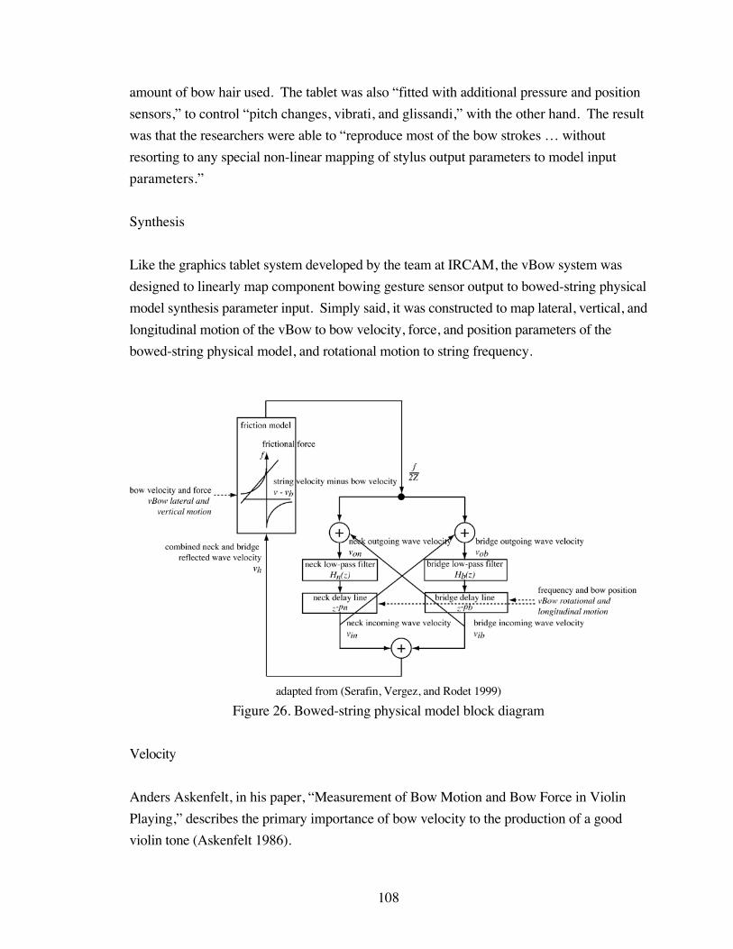
108
amount of bow hair used. The tablet was also “fitted with additional pressure and position
sensors,” to control “pitch changes, vibrati, and glissandi,” with the other hand. The result
was that the researchers were able to “reproduce most of the bow strokes … without
resorting to any special non-linear mapping of stylus output parameters to model input
parameters.”
Synthesis
Like the graphics tablet system developed by the team at IRCAM, the vBow system was
designed to linearly map component bowing gesture sensor output to bowed-string physical
model synthesis parameter input. Simply said, it was constructed to map lateral, vertical, and
longitudinal motion of the vBow to bow velocity, force, and position parameters of the
bowed-string physical model, and rotational motion to string frequency.
adapted from (Serafin, Vergez, and Rodet 1999)
Figure 26. Bowed-string physical model block diagram
Velocity
Anders Askenfelt, in his paper, “Measurement of Bow Motion and Bow Force in Violin
Playing,” describes the primary importance of bow velocity to the production of a good
violin tone (Askenfelt 1986).
109
Physically, the momentary velocity of the bow is one of the player’s chiefcontrols of the sound level, the excursion of the string being directlyproportional to the bow velocity.
Supporting this assertion, Percival Hodgson, in his text, Motion Study and Violin Bowing
(Hodgson 1958), explains the influence of the lateral bow stroke on the amplitude of string
vibration, or loudness.
The volume of the sound is decided by the amplitude, or width, of thevibrations. An increase in power is therefore achieved by adding to the pullor push exerted sideways on the strings.
Similarly, Walter Kolneder, in his book, The Amadeus Book of the Violin (Kolneder 1998),
affirms that the loudness of the violin is affected by bow velocity, in concert with bow force.
Tone volume depends chiefly on the speed of bowing and bow pressure,which affect the amplitude of the vibration.
Both the first version of the vBow, which only allowed for lateral motion, and the current
version, have shown that the bowed-string physical model used in the vBow software,
responds expressively to the player’s control of bow velocity. For both versions of the
vBow, the sampled encoder reading, from the shaft rotation of the servomotor for the lateral
degree of freedom, is used directly as data for the velocity parameter of the bowed-string
physical model. The sampled encoder count, divided by the maximum encoder count for
the length of the cable, and added to a velocity offset, is passed to a method of the bowed-
string object, which changes the bow velocity value of the Friedlander friction function. If
the stick of the vBow, and consequently the attached cable spinning the capstan secured to
the servomotor shaft, is moved in a lateral motion at an optimal speed, which is analogous to
the normal draw of a bow across a violin string, the physical model responds with a clear
bowed-string sound.
The Dictionary of Bowing Terms for Stringed Instruments (Seagrave and Berman 1976)
explains that flautando, “a light airy style of bow-stroke” also called flautato, is produced
by varying the bow velocity.
A high ratio of bow speed to pressure is employed to produce the ‘flute-like’ tone quality.

110
In addition to responding to an optimal bow velocity, by producing a clear tone, the bowed-
string physical model also responds to fast and slow bow strokes of the vBow, by
producing changes in the brightness of the timbre. If the lateral motion of the vBow is
faster than optimal, spinning the servomotor shaft encoder quickly and sending high bow
velocity values to the synthesis software, the bowed-string physical model produces a
flautando timbre, bringing out the higher partials. If the lateral motion is slower, producing
low bow velocity values, the physical model produces a scratching sound, similar to the hair
of the bow scraping along a violin string, too slowly to excite a steady-state vibration.
Frequency
The frequency of the note played is the result of a bowing parameter inasmuch as the player
rotates the bow across the strings of the violin to choose which string to bow. Because the
vBow is not currently used in conjunction with a vString, or linear position sensor virtual
string, rotation of the vBow is so far the only means possible to change the velocity
parameter of the bowed-string physical model, in the vBow software.
Currently, the bowed-string physical model responds to the rotational motion of the vBow
by playing the frequencies of the open strings of a violin. As the stick and housing piece of
the vBow rotate, spinning the capstan attached to the servomotor for the rotational degree of
freedom with the corresponding cable, the quantized reading of the encoder is mapped to the
frequency of the pitch played by the physical model. In the vBow software, the maximum
encoder count, for the length of cable secured to the bottom of the rotation piece, is divided
by four, so that when the encoder senses that the vBow has rotated into each quarter length,
the bowed-string physical model receives one of four frequencies, corresponding to the four
open strings. These frequencies are used by the bowed-string object to calculate the base
delay line length, from which the bridge and neck delay line lengths are calculated, for the
reflected waves of the Helmholtz motion.
Force
Like his observations about bow velocity, Askenfelt explains the effect of bow force in
terms of its influence on the behavior of the string.
According to the basic Helmholtz model of string motion, the bow forcedoes not influence the vibrations of the string, provided the frictional forcebetween bow and string is high enough to maintain the stick-slip process of

111
the string under the bow. However, as familiar to all string players, the bowforce does affect the string vibrations, an increased bow force giving aperceptually more “brilliant” tone quality.
The scientist continues by describing the role that bow force plays, interacting with the
reflected Helmholtz motion, in order to produce this brilliant tone.
This change in tone quality with bow force is due to the fact that thecirculating corner is rounded off at the periodical reflections at the stringterminations, mainly at the bridge. During the passage under the bow thecorner is resharpened, an effect which becomes more prominent withincreasing bow force. This resharpening effect enables the player to boostthe higher partials in the radiated spectrum by increasing the bow force.Such a change in spectral content will affect the tone quality as mentioned,but at the same time the perceived loudness will increase, although theamplitude of the string vibrations remains essentially unaltered.
Lothar Cremer, in his paper, “The Influence of ‘Bow Pressure’ on the Movement of a
Bowed String: Part I,” also describes the importance of bow force in terms of how it is
used to change tone quality (Cremer 1972).
… change in bow pressure is of importance to the player as his third meansfor changing the sound of his instrument, especially in that it changes thetimbre.
As stated in the section about bow velocity, Kolneder reinforces the importance of bow
force, in combination with bow speed, to the volume of the tone produced by the bowed
string. Hodgson also writes about this cooperative influence of bow force and velocity on
tone production.
Downward pressure in itself tends to prevent free vibration, and thusstrangles the tone. It is only used comparatively slightly in order to pull thestring, and will obviously need to be proportionate to the sideways forceemployed at the time.
Askenfelt additionally describes the interaction between bow force and position, again
characteristically in terms of string behavior, as well as performance practice.
The minimum bow force required to maintain the string oscillationsincreases as the bow is moved closer to the bridge. The player observes thislaw by normally increasing the bow force while decreasing the bow-bridgedistance.
112
Similarly, John Schelleng describes the interaction between bow force, velocity, and
position, as it relates to the violinist’s control of dynamics (Schelleng 1973).
Bow force is important primarily as the catalytic agent that makes possiblea correct reaction between bow speed and bow position. Usually oneincreases volume by increasing both velocity and force or by bowing closerto the bridge and increasing force.
The bowed-string physical model has proven to be responsive to bow force values
approaching and exceeding the optimal value, as generated by the vertical motion of the
vBow, and preliminary results have shown that the interaction between bow force and the
other two bowing parameters produces the expected dynamic and timbral variations in tone.
The reading from the encoder on the servomotor for the vertical degree of freedom is
mapped to the bow force parameter in the physical model. Like the encoder count for lateral
motion, the sampled encoder reading for vertical motion is divided by the maximum encoder
count for the length of cable used, and that value is used directly for the bow force
parameter in the bowed-string physical model.
In the vBow software, the encoder reading for the cable length is divided into two regions of
above and below the point of optimal bow force. As the vBow is moved downwards toward
the violin-shaped body, the bow force value increases. As it is lowered toward the point of
optimal bow force, the bow force value approaches one, and as it is pushed beyond the
optimal point, the bow force exceeds one.
In the first case, the encoder reading is divided by the maximum encoder count for the upper
region, and subtracted from one. In the second case, the absolute value of the encoder
reading is divided by the maximum count for the lower region, and added to one. In both
cases, the resultant value is used by the bowed-string object to change the force value of the
Friedlander function in the bowed-string physical model.
As the stick, housing, rotation, and arm pieces of the vBow are lowered, bow force increases
toward the point of optimal force, and the loudness and fullness of timbre increases in the
bowed-string physical model. As the vBow assembly is pushed further toward the body
piece, bow force increases beyond the point of optimal force, and the timbre darkens, until
the force is great enough to stop the oscillation of the physical model, simulating a bow
pushing against the string with enough force to keep the string from vibrating.
113
Position
According to the Dictionary of Bowing Terms for Stringed Instruments, the contact point
between the hair of the bow and the string, or “the distance of the bow from the bridge” is
very important for the timbre produced by the violin, describing it as “a crucial factor in the
control of tone production.” In the same entry, it is also explained that the tone produced at
this contact point changes in relation to other bowing parameters: “The point at which the
desired sound is produced will vary according to the speed and pressure of the bow.”
As with the other bowing parameters, Askenfelt explains the use of bow position for
controlling the tone of the violin, from two perspectives. First the author describes the
physical effect of bow force on the string.
String physics tells that the string spectrum will include a continuoussuccession of partials up to an order number proportional to the ratiobetween string length and bow-bridge distance.
Next the scientist explains the player’s technical considerations of bow force.
… bowing close to the bridge will reinforce the higher harmonicsconsiderably compared to the lower harmonics. In addition, loudness willalso increase, …
Kolneder also attests to the importance of bow position to the quality of the tone produced
by the bowed string, naming it as the primary component determining the quality of tone
produced, and describing changes in elasticity and timbre, as the bow moves toward the
bridge and fingerboard.
Timbre is determined by many factors, but chiefly by the bow’s point ofcontact with the string. A normal violin tone results from bowing at adistance of ca. 20 mm from the bridge; … . Closer to the bridge, the stringis harder, offering more resistance to the bow, … . Near the bridge the tonegrows louder but also harsher because certain higher overtones are moreprominent. … Composers of program music especially occasionally wantthis effect, indicating it in the music by the words “sul ponticello” (at thebridge). Placing the bow closer to the fingerboard, closer to the largestamplitude of the string, the bow meets with less resistance; the tone is moregentle but also weaker. Composers who desire this effect indicate it with thewords “sulla tastiera” (over the fingerboard). Choosing the bow’s point ofcontact with the string is essential for regulating dynamics and timbre.
114
These expressive markings, sul tasto and sul ponticello, are also discussed in relation to the
contact point of the bow, by composer and educator, Samuel Adler, in his treatise, The Study
of Orchestration (Adler 1982). He explains, in technical and musical terms, that sul
ponticello or “playing very near or, in fact, right on the bridge instead of in the regular
space allotted for the bow stroke” changes the timbre of the violin by accentuating the
“upper partials of the tone not usually heard,” producing an “eerie, metallic, and somewhat
glassy timbre.” Similarly, he describes sul tasto or the technique of playing “with the bow
over the end of the fingerboard” as producing a “rather flutey, soft, and hazy tone.”
In the introductory chapter on stringed instruments in Walter Piston’s seminal text,
Orchestration (Piston 1955), the composer and teacher also describes how bow position
changes the timbral quality of the tone produced.
The bow is drawn at right angles to the string, ordinarily at a place abouthalfway between the bridge and the end of the fingerboard. For a louder andmore brilliant tone, and for the normal production of high notes, the bow isplayed nearer the bridge. For softer tones it is moved nearer to thefingerboard.
Later in the same chapter, in a section entitled “Effects of Color,” Piston details the
technique behind sul tasto.
To obtain a tone of very soft floating quality the strings may be directed toplay on the fingerboard. The bow is placed so far from the bridge that it isactually over the upper part of the fingerboard, where there is greateramplitude in the vibration of the string.
The composer continues to direct the student in the mechanics of sul ponticello, once again
describing the timbral variety produced.
Playing with the bow very close to the bridge, or even upon it, produces aspecial kind of sound, due to the bringing out of upper partials not usuallyheard. The sound has been called glassy and metallic.
Like an acoustic violin, the physical model responds to longitudinal motion, by changing the
timbre of the bowed-string sound. As the vBow assembly moves longitudinally toward the
player, the timbre changes from a normal violin sound, to a richer and noisier sul ponticello
timbre, and as it moves away from the player, the timbre changes to a lighter and softer sul
tasto sound.
115
The reading from the encoder on the servomotor for the longitudinal degree of freedom is
mapped to the bow position parameter of the physical model, in the vBow software. Like
the encoder readings used for bow force, the encoder count for the length of cable used for
bow position is divided into two regions.
After the initial position of the servomotor shaft and attached encoder is set, the encoder
readings are read above the initial position as positive, and below this point as negative, as
the entire vBow assembly is moved longitudinally toward and away from the player.
Although the readings from the upper and lower encoder count regions are later normalized
to between zero and one, dividing the length of cable used for longitudinal motion by an
initial position ensures that the ranges of motion and encoder readings for sul ponticello and
sul tasto effects will be of the desired length.
The encoder count for longitudinal motion is used by the physical model object to calculate
the lengths of the delay lines representing the segments of string between the bow contact
point and the bridge, and the bow contact point and the string termination at the nut or left-
hand finger contact point.
The longitudinal position of the vBow, or virtual bow contact point, is scaled and multiplied
by the base delay line length, which is determined by the frequency parameter of the
physical model, to calculate the lengths of the bridge and neck delay lines. The bridge delay
line length equals the scaled longitudinal position multiplied by the base delay line length,
while the neck delay line length equals the scaled longitudinal position subtracted from one
and multiplied by the base delay line length, or the remainder of the length of the virtual
string.
Haptics
In addition to directing the mappings from the output of the encoders to the input
parameters of the bowed-string physical model, the vBow software also controls the voltage
output from the servomotor control card to the servomotors, simulating various kinds of
haptic feedback.
The control software, which produces the haptic feedback of friction and vibration for the
lateral motion, detents for the rotational motion, elasticity for the vertical motion, and friction
for the longitudinal motion, was also written in C++, using the libraries that came bundled
116
with the ServoToGo servomotor control and data acquisition card
(http://www.servotogo.com/).
Vibration
To simulate the vibration of the string as felt on the bow, the vBow software maps the output
of the bowed-string physical model sound synthesis directly to the servomotor attached to
the housing piece, that provides the haptic feedback corresponding to lateral motion. The
result is a force feedback simulation of vibration, that directly relates to the sound synthesis
of the system.
Like the function used to map lateral motion to the bow velocity parameter of the bowed-
string physical model, for sound synthesis, the vBow software uses the sampled sensor
reading from the encoder tracking lateral motion, divided by the maximum encoder count
for the length of cable used to spin the capstan attached to the servomotor shaft secured to
the housing piece, as the parameter value for the method that changes the velocity value for
the bowed-string physical model. The output tick of the physical model is then scaled and
passed to the function, that outputs a voltage through the servomotor control card, to the
servomotor that simulates haptic feedback for lateral motion.
As the stick of the vBow, and the corresponding cable, is drawn laterally, the periodic
vibration produced by the servomotor, from the scaled bowed-string physical model output
converted to a voltage, is felt at the frog.
Friction
Based on a photo of the microscopic barbs on a bow hair, and the speculation that the barbs
of multiple hairs strung on a bow are naturally misaligned, the first version of the vBow
used a simple randomly triggered alternating voltage to simulate the feel of a bow catching
and releasing a violin string.
This simple function compared the absolute value of the sampled encoder reading to a
random number modulo a constant limit plus a constant offset. If the absolute value of the
encoder reading was greater than the calculated value, alternating scaled voltages were
passed to the function that controlled the output of voltages from the servomotor control
card to the servomotor. The output voltages, alternating between positive and negative

117
voltages for down bows, and between negative and positive voltages for up bows, were
delayed by a sleep function, passed a duration value calculated again by a random number
modulo a constant limit plus a constant offset.
The resulting haptic friction simulation felt like a semi-periodic vibration that added some
resistance to the lateral bowing motion.
The friction model, used to control the servomotors for both the lateral and longitudinal
degrees of freedom of the current version of the vBow, was developed by Vincent Hayward
and Brian Armstrong, from a model previously conceived by Dahl (Hayward and
Armstrong 2000), and was programmed by Sile O’Modhrain, for her research into the
affect of adding haptic feedback to virtual musical instrument systems (O’Modhrain 2000).
Dahl’s stick-slide friction model defines frictional force as proportional to the strain
between an adhesion point and a moving mass connected by a spring. When the strain
reaches a maximum value, the adhesion point breaks from its position and slides in parallel
with the mass.
Hayward and Armstrong’s stick-slip-slide friction model adds to this maximum value an
additional “stick” parameter, that when less than or equal to the maximum value, allows for
the stick-slide behavior of the adhesion point, as previously described for the Dahl model,
but when greater than the maximum value, provides for the adhesion point to slip and stick
again, “yielding relaxation oscillations akin to a stick-slip behavior.”
The output of the encoders used to track lateral and longitudinal motion of the vBow
hardware is used as data for one of the parameters of this stick-slip-slide friction model in
the vBow software. Consequently, the output of the friction model is sent as varying
voltages to the servomotor for both degrees of freedom, producing the haptic simulation of
friction, corresponding to lateral and longitudinal motion.
As the player draws the vBow laterally or moves the vBow longitudinally, the sampled
encoder reading value is used by the friction model as the position of the moving object. In
the function that calculates frictional force according to the Hayward and Armstrong friction
model, an “adhesion map” value is set to zero, if the absolute value of the strain between
the adhesion point and the position of the moving object, or sampled encoder reading, is less
than or equal to the “stick” constant, that determines at what amount of strain the adhesion
118
point starts to slip. If the absolute strain is greater than this stick value, the adhesion map
value is set to one divided by the maximum strain constant.
When this adhesion map value, which “controls the rate of change” of the strain between
the adhesion point and the moving mass, times the absolute value of the strain, is greater
than one, and the strain is greater than zero, the adhesion point is moved to the previous
point plus the maximum strain constant. If the strain is less than or equal to zero, then the
adhesion point is moved to the previous point minus the maximum strain constant. But,
when the adhesion map value, times the absolute strain, is less than or equal to one, then the
adhesion point equals the old point plus the absolute value of the current moving mass
position, or encoder reading, minus the previous position, times the adhesion map value,
times the strain value.
Finally, frictional force is calculated from the current moving mass position, or encoder
reading, minus the current adhesion point, times a spring stiffness constant. This frictional
force value is then multiplied by a scaled voltage, and passed as a parameter to the function
that sends a voltage, from one of the digital-to-analog converters of the servomotor control
card, to the servomotor used to simulate haptic feedback for lateral or longitudinal motion.
The result is the feeling of nonperiodic roughness, as the vBow is moved back and forth, or
forward and backward, and the capstan attached to the corresponding servomotor engages
or releases the cable, attached to the vBow piece for that motion.
The resolution of the simulated friction, or the amount of strain required to move the
adhesion point, can be adjusted by the value of the maximum strain and stick constants,
making the spring feel larger or smaller, just as the rigidity of the spring can be varied by
the stiffness constant, causing the spring to feel stronger or weaker. Furthermore, because
the haptic feedback of friction is simulated independently of vibration, the parameters of
each function can be individually adjusted, in the vBow software, to separately vary the
effect of each type of force feedback.
Detents
Inspired by a lecture given by Vincent Hayward, on his research with a haptic device called
the Pantograph (Ramstein and Hayward 1994), and his subsequent work simulating virtual
surfaces (Robles-De-La-Torre and Hayward 2000), the force feedback of detents,
simulating the feel of a bow crossing violin strings, is produced by varying the amount and

119
direction of force applied to the servomotor for the rotational degree of freedom of the
vBow. The general definition of the term detent is used in this case, to describe a
mechanism that holds a part in place until it is released by an opposing force.
The haptic feedback of detents is produced by applying an increasing, then decreasing
opposing force, followed by an increasing, then decreasing parallel force to the rotational
degree of freedom. The result is a simulation of the feel of a bow rolling over the round
surface of four violin string, as the vBow swivels from one side to the other, through the
length of cable attached to the bottom of the rotation piece.
In the vBow software, the maximum encoder reading, for the length of cable that spins the
capstan attached to the servomotor for rotational motion, is divided into four regions, each
corresponding to one string. Each of the four regions, of cable length and encoder readings,
is further divided into three segments, corresponding to a string, with space on either side.
Each segment is additionally divided into six slices, representing the six force values used to
simulate the slope of the surface of the string.
As the vBow hardware rotates through the length of cable and range of encoder values, the
vBow software registers when the controller is in a region, for each string, a segment,
representing a string or a space on either side, or a slice, in which the software produces
opposing and parallel full and half forces. As the vBow swivels, starting at one end, the
encoder values move through one segment, representing space on the side of the string,
through the first slice, of the second segment, representing the virtual string surface, with a
half opposing force, at the bottom of the ascending slope of the virtual string surface,
through the second slice, with a full opposing force, at the middle of the slope of the surface,
through the third slice, again with a half opposing force, at the top of the slope, through the
fourth slice, with a half parallel force, at the top of the descending slope, through the fifth
slice, with a full parallel force, in the middle, through the sixth slice, again with a half parallel
force, at the bottom of the descending slope, and at the end of the virtual string surface, into
the third segment, representing the space on the other side of the string. As the vBow
continues to rotate, it moves through three more groups of encoder reading segments, and
surface contour simulating force slices.
These opposing and parallel full and half forces are scaled and passed to the function that
produces a voltage on the servomotor control card, engaging the servomotor and
corresponding cable.

120
Elasticity
As Hodgson is describing the relationship of bow position to bow velocity and force, the
author not only describes the timbral changes that the performer responds to, but also the
kinesthetic cues, implying that haptic feedback is as valuable as auditory feedback, when
sensing correct bow placement.
… no study of tone production is adequate which does not focus aconsiderable amount of attention on feeling the tension of the stringconsciously with the bow, while seeking a relatively constant resistance.This search for the ideal place of contact becomes instinctive to the fineplayer, who listens at the same time to the resulting variations in tone quality,and thus develops his sense of touch to a high degree.
The simulation of this combined elastic resistance of the violin string and bow hair, as the
bow pushes into the string, is produced in the vBow software, by a linear mapping of the
encoder position, in relation to a maximum encoder reading, to the voltage applied to the
servomotor, for the vertical degree of freedom of the vBow, producing a continually
increasing or decreasing force. As the assembly is lowered vertically toward the violin-
shaped body, the player encounters an elastic resistance, that increases as the vBow is
pushed down, and decreases as it is lifted. Furthermore, if the assembly is dropped from an
elevated position, the haptic simulation will cause the vBow to bounce, or if it is pushed
downward, into the elastic resistance, and released, the force feedback will cause the
controller to spring upward.
To simulate this elastic resistance, the vBow software simply scales the voltage value, which
is passed to the function that controls the servomotor that corresponds to vertical motion, by
the sampled encoder position, divided by the maximum encoder count for the length of
cable that spins the capstan and shaft of the same servomotor. In order to model the
freedom of movement above the violin, before the bow contacts the resilience of the string,
the elastic resistance is simulated below a encoder count threshold, that is set at the
initialization of the control software.
In addition to simulating elastic resistance for the vertical degree of freedom of the vBow,
this direct mapping of the normalized sampled encoder count to scaled voltage is used to
produce the haptic feedback of barriers for longitudinal motion. Although the same
mapping is used, the normalized encoder count range corresponds to a much shorter length

121
of cable, so the elastic resistance increases much more quickly, resulting in haptic feedback
that feels more like a barrier than a spring.
As the player moves the vBow longitudinally, if the encoder count, from the cable spinning
the capstan and shaft of the servomotor for longitudinal motion, is within the range of a
maximum and minimum threshold, the haptic feedback of friction, described in the context
of the force feedback for lateral motion, is simulated for longitudinal motion. If, however,
the encoder reading is outside either the maximum or minimum threshold, then the encoder
count of the minimum threshold is added to or subtracted from the sampled encoder count,
and divided by the length of the region outside the threshold, ending at either end of the
cable. Within these encoder count ranges, at the ends of the cable, the force feedback
quickly increases, producing the haptic effect of a rigid barrier.

122
CHAPTER 6
APPLICATION
Overview
The vBow has been designed as a musical controller, for transducing performance gesture
into sound synthesis parameter data, and as a haptic human-computer interface, for
simulating force feedback cues, with the superseding goal of developing an expressive
instrument, that provides the composer with a wide range of dynamic and timbral contrasts,
and the performer with a subtle responsiveness and versatile sensitivity. Further
development of the vBow hardware and software will endeavor to integrate the mapping of
bowing gesture to sound synthesis and haptic feedback, into an expressive interactive
computer music composition and performance system.
These future developments will include mapping performance gesture to other types of
sound synthesis and simulating additional kinds of force feedback, in the dynamic context
of a performed composition.
Synthesis
In addition to playing the bowed-string physical model, described in the previous chapter
about the vBow software, the instrument will be used to test the playability of other physical
models. For instance, the vBow is an ideal instrument for evaluating the bowed-string
physical model that accounts for torsional waves, and includes a friction model that
simulates the “’plastic’ deformations at the bow-string contact” due to melting rosin, that
researchers at CCRMA and the University of Cambridge tested, using a computer
simulation that resulted in a Schelleng diagram of timbre (Serafin, Smith, and Woodhouse
1999). Similarly, the vBow is well suited to test the effect of different attacks, produced by
various initial bow velocities and forces, on the output of bowed-string physical models, as
the same researchers at CCRMA studied, again through the use of computer simulations
and Schelleng diagrams (Serafin and Smith 2000).
Other physical models that would be interesting to incorporate into the vBow sound
synthesis software, include the “exciter-resonator” models of a glass harmonica and bowed
saw, in which the excitation is simulated by either a friction or spectral model, and the
resonator is comprised of digital waveguides (Serafin et al. 2002), and a Tibetan singing

123
bowl, modeled with circular waveguide networks (Serafin, Wilkerson, and Smith 2002),
developed by research groups, headed by Stefania Serafin, at CCRMA.
Along with the inclusion of other physical models in the vBow software, future
developments include the implementation of polyphony, so that more than one string can be
bowed at a time. Because of the latency of the currently used computer hardware and
operating system, a faster CPU and possibly RTLinux will be necessary, to simultaneously
track four encoder positions, while generating the sound synthesis, as well as the haptic
feedback, for multiple strings, in real-time.
While mapping component bowing gestures to bowed-string physical model synthesis
parameters is an obvious fit, the vBow is also a suitable controller for the real-time
performance of other programmed sound synthesis instruments. When mapping the
degrees of freedom of the vBow, to bowed-string physical model parameters, there is a
direct correlation between the composite bowing gesture and sound synthesis parameters,
due to the development of both the vBow and the bowed-string physical model, according to
the mechanics of the interaction between a bow and a violin string. In order to imitate this
one-to-one relationship, mappings of constituent bowing gestures, to parameters of other
kinds of sound synthesis, such as signal models, will be chosen according to how closely
the pairings emulate the acoustic response expected from bowing a violin. As suggested in
David Jaffe’s influential paper on evaluating synthesis techniques, signal models will be
chosen for the vBow software, that provide parameters that “map in an intuitive manner to
musical attributes,” as well as produce an “obvious audible effect” when changed (Jaffe
1995).
Strategies for mapping between musical controllers and sound synthesis programming are
the subject of several papers in computer music literature (Bowler et al. 1990; Winkler
1995; Rovan et al. 1997; Wanderley, Schnell, and Rovan 1998; Garnett and Goudeseune
1999; Hunt, Wanderley, and Kirk 2000; Wanderley 2001; Hunt, Wanderley, and Paradis
2002). In one such paper, Todd Winkler advises that when mapping performance gestures,
that are “free from the associations of acoustic instruments,” to synthesis parameters, it
should be understood that the system includes “similar limitations that can lend character to
sound through idiomatic movements” (Winkler 1995). Although this recommendation was
made in the context of using “the body and space as musical instruments,” this strategy, of
ensuring that “the sound reflects … the effort or energy used to create it,” is just as
important, to producing “musically satisfying results,” when mapping controller output to
124
synthesis input. This concern for the musical propriety of mapping strategies, as expressed
by Jaffe and Winkler, will guide the choices made for the one-to-one pairings of vBow
motions to synthesis parameters.
But, one-to-one mappings are by no means the only possibility. In a subsequent paper, a
team from IRCAM, including Butch Rovan, Marcelo Wanderley, Shlomo Dubnov, and
Philippe Depalle, employed different strategies for mapping the output of a Yamaha WX7
MIDI wind controller to the input of a FTS real-time digital signal processing system
(Rovan et al. 1997). For these authors, the mapping strategy is as important to the
expressivity of an interactive performance system, as the gestural controller and synthesis
software. This is especially the case when a signal model, such as additive synthesis, with
its many time-varying parameters, is used for the synthesis software. When mapping
controller output to the many inputs of an additive synthesis signal model, the right strategy
can allow for “higher level couplings between control gestures.”
The authors categorized these strategies as “one-to-one mapping,” in which “each
independent gestural output is assigned to one musical parameter,” “divergent mapping,”
where “one gestural output is used to control more than one simultaneous musical
parameter,” and “convergent mapping,” in which case “many gestures are coupled to
produce one musical parameter.” In addition to considering the musical propriety of what
kinds of motion are directly mapped to what types of synthesis parameters, the vBow will
allow for an exploration of other mapping strategies. As discussed in the chapter about the
motivations behind this project, each degree of freedom of the vBow will be used to control
the behavior of one parameter for multiple partials of resynthesis, like a global envelope
shaping the behavior of multiple local envelopes.
In addition to controlling the time-varying behavior of this hybrid approach to additive
synthesis, resynthesizing each partial with a sine wave, formant-filtered pulse-train,
frequency-modulating pair of oscillators, or plucked-string physical model, the vBow also
will be used to experiment with the sound synthesis of ring modulation, waveshaping,
scanned synthesis, and granular synthesis, as well as real-time interactive spatialization of
sound.
Ring-modulation, like frequency-modulation, allows for a one-to-one mapping, that
emulates the acoustic response produced by bowing a violin. In most cases lateral motion
will map to overall dynamic, or in these cases carrier amplitude, and rotational motion will

125
map to pitch, or for these signal models carrier frequency. Because bow-bridge distance is
naturally associated with changes in timbre or brightness, longitudinal motion maps well to
modulator amplitude or index, leaving bow force to map to modulator frequency, which
correlates well to changing the carrier frequency with rotational motion: while amplitude
parameters are mapped to motion along the horizontal plane, frequency parameters are
mapped to motion within the vertical plane.
Like ring- and frequency-modulation, waveshaping synthesis efficiently produces spectrally
complex timbres, with parameters that map intuitively to the degrees of freedom of the
vBow. Again, as with the previous example, lateral motion could be used to scale the overall
amplitude, and rotational motion could be used to sweep through the frequency range, of the
sine wave used to read through the lookup table, of the transfer function that shapes the
wave. And, again, because bow position is used to control the brightness of the timbre of an
acoustic violin, longitudinal motion could be used to control the amplitude of the sine wave,
increasing the higher frequencies as the vBow is moved toward the player. Similarly, in the
case where the amplitude of the sine wave being shaped is controlled by another wave, the
longitudinal motion could be mapped to modulation amplitude or depth, again controlling
the brightness of the timbre with bow position, while vertical motion could be mapped to
modulation frequency or rate, regulating the speed of timbral sweep or pulse below audio
range, and producing side-bands at audio rate, with bow force. Alternatively, rotational
motion could be used to choose between various lookup-table transfer functions, and bow
force could be used to pick different waveforms to shape.
Another synthesis technique involving wavetable lookup, called scanned synthesis, was
developed at Interval Research, and first described by Bill Verplank, Max Mathews, and
Robert Shaw, in which the shape of a virtual vibrating string is directly manipulated with a
controller, producing variations in its timbral output (Verplank, Mathews, and Shaw 2000).
This virtual string is modeled with masses interconnected by springs, and grounded by
parallel springs and dashpots, and the shape of this physical system is periodically scanned,
at a frequency that determines the pitch of the virtual vibrating string. A controller is used to
excite the masses, and the displacement of each mass is stored as an amplitude value in a
dynamic wavetable.
Extensions to this synthesis technique have been developed by Richard Boulanger, Paris
Smaragdis, and John ffitch, in which masses can be connected by multiple springs with
independent stiffnesses, producing physical systems of various shapes and with different

126
vibration behaviors, that can be read by diverse scanning trajectories (Boulanger, Smaragdis,
and ffitch 2000).
The vBow could be used to bow one of these scanned virtual strings or surfaces, controlling
the excitation with lateral and vertical motion, producing various percussive attacks.
Furthermore, rotational motion could be used to change the scanning frequency, again using
vBow rotation to change pitch, and longitudinal motion could be used to vary the spring
stiffnesses. Once again, the expressive potential of this synthesis technique could be
explored by experimenting with different mapping strategies between the vBow sensor
output and synthesis parameter input.
One of the synthesis techniques I have enjoyed experimenting with, in the context of
realizing a composition for MIDI violin, computer, and sampler, has been granular
synthesis, using Fernando Lopez-Lezcano’s “grani” instrument, programmed in Bill
Schottstaedt’s Common Lisp Music sound synthesis and signal processing package.
Among many other parameters, Lopez-Lezcano’s granular synthesis instrument allows for
control over the duration of the grain of samples taken from a sound file, where in the sound
file the grain is taken from, and the density of grains within the resynthesized sound file. In
addition, the programmed instrument provides parameters that determine a range of random
variation to be applied to these values.
The vBow will be an excellent controller for interfacing with this granular synthesis
instrument. As with the other mapping strategies, lateral motion will naturally control
overall amplitude, but because of the multiple parameters to vary, in Lopez-Lezcano’s grani
instrument, a divergent strategy will be necessary. Vertical motion could control grain
width, longitudinal motion could map to grain density, and rotational motion would vary
sound file location, while simultaneously influencing the random variation between values,
with a function relating each range of motion with an array of random values. Alternatively,
lateral motion could be mapped, in parallel with amplitude, to independently expanding and
contracting ranges of random values, for each parameter.
Finally, it will be interesting to experiment with controlling the spatialization of sound, with
the degrees of freedom of the vBow. While lateral and vertical motion could be mapped to
synthesis parameters, rotational motion could be used to sweep the output of the system
across the stereo field, with longitudinal motion moving the sound to the front and back.
From the perspective of the violinist, it would be a natural mapping to use bow velocity and

127
force to generate the sound, an arching movement to pan from left to right, and motion
toward and away from the player to send the sound backward and forward.
Haptics
Along with mapping the vibrations associated with the output of additive and subtractive
synthesis, amplitude- and frequency-modulation, waveshaping, scanned synthesis, and
granular synthesis, to the servomotor corresponding to lateral motion, simulating the elastic
resistance that corresponds to the spring stiffnesses of the scanned synthesis physical
model, with the servomotor for vertical motion, and using the haptic feedback of friction,
elasticity, and viscosity to assist with navigating through the range of values for each of the
other synthesis parameters, the vBow will be used to experiment with the simulation of
haptic cues associated with advanced bowing techniques, as well as force feedback that has
no analogue in the physical world.
In a chapter about the mechanical properties of the bow, in a book detailing his motion
studies of violin bowing, Percival Hodgson describes the key to off-the-string bowing
technique, not in terms of how it sounds, but according to how it feels to the player
(Hodgson 1958).
… the first step in cultivating martellato, solid or flying staccato, spiccato,sautillé, or ricochet, is to find the part of the bow which provides the precisedegree of elasticity required;
Likewise, in The Study of Orchestration, Samuel Adler describes spiccato as “a conscious
effort to make the bow ‘spring’” (Adler 1982), and Walter Piston, in his treatise,
Orchestration, explains that this type of bowing “makes use of a springing or bouncing of
the bow-stick” (Piston 1955).
As described in the previous chapter about the vBow software, preliminary results show that
the vBow is capable of producing the same spring as a bow bouncing on the violin string.
Although a simple spiccato bowing may be currently possible, the response of the haptic
simulation of combined bow and string elasticity may need refinement, to provide for more
sophisticated off-the-string bowing, such as jeté, a slurred spiccato. Furthermore,
simulation of string elasticity will need to be varied, according to longitudinal position, just
as string resistance varies as the violinist moves the bow from at the bridge, where resistance
is high, to over the fingerboard, where resistance is low. The same is true for the simulation
128
of bow elasticity, which should vary according to lateral motion, with less resistance at the
middle, and more at the tip and frog.
In addition to replicating the force feedback associated with synthesis models or bowing
techniques, the vBow will be used to experiment with generating new potentially useful
haptic cues. For instance, the system could be used to simulate multiple layers of strings
that when bowed with an optimal force, produce the expected friction and vibration, but
when pushed harder, give way to another set of strings below. Furthermore, the vBow
software could simulate the haptic effects of different materials and various windings for
each layer of strings. For instance, one set of strings could be nylon, another steel round-
wound, and the other silver flat-wound.
Although simulating multiple levels of strings made with different textures from various
materials is currently only an idea, research into modeling different surface textures and
material properties, that may assist with this application for the vBow, is being performed by
other researchers. Christian Müller-Tomfelde and Tobias Münch, at the Integrated
Publication and Information Systems Institute in Darmstadt, have modeled the sound of a
pen drawing on different surfaces (Müller-Tomfelde and Münch 2001), and Federico
Avanzini and Davide Rocchesso, at the Universities of Padova and Verona, have simulated
the collision sounds of a hammer hitting rubber, wood, glass, and steel. While both
research groups are focused on producing the sounds corresponding to interacting with the
texture or material of a surface, the resulting output from their systems may be useful for
simulating the haptic cue of vibration. Further study of previous research into the haptic
simulation of surface texture and material properties is clearly the next step.
Composition and Performance
In the aforementioned paper, Winkler advocates that interactive music systems be used to
extend “the performer’s power of expression beyond a simple one-to-one relationship of
triggered sound, to include the control of compositional processes, musical structure, signal
processing, and sound synthesis.” Because the system software can map the four encoder
readings to any sound synthesis or musical algorithm parameter, the vBow is ideally suited
for this kind of high level control of compositional process and musical structure.
Furthermore, because the output voltage of any haptic simulation can be mapped to each of
the four servomotors of the vBow hardware, the force-feedback of the instrument can
change along with the sound synthesis or musical algorithm. Because the feel of the

129
instrument can change between or even within pieces, force-feedback can now be used as a
compositional element, limited only by the range of motion of the performer, and the
imagination of the composer.
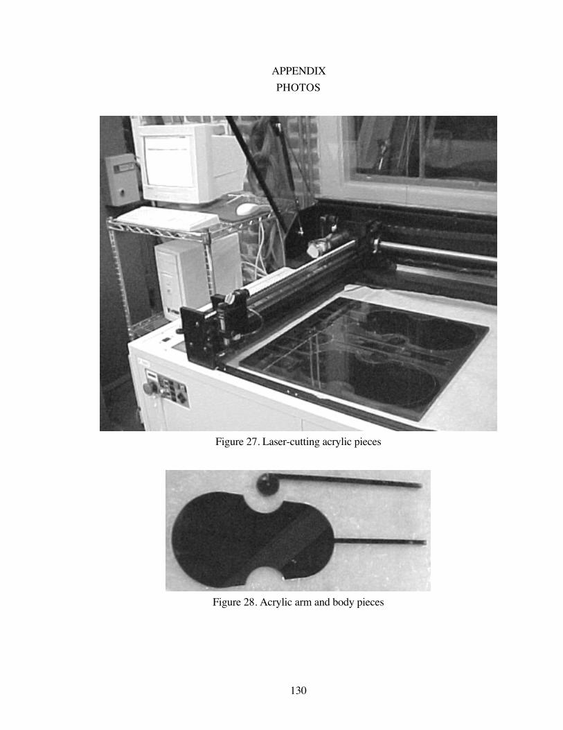
130
APPENDIX
PHOTOS
Figure 27. Laser-cutting acrylic pieces
Figure 28. Acrylic arm and body pieces
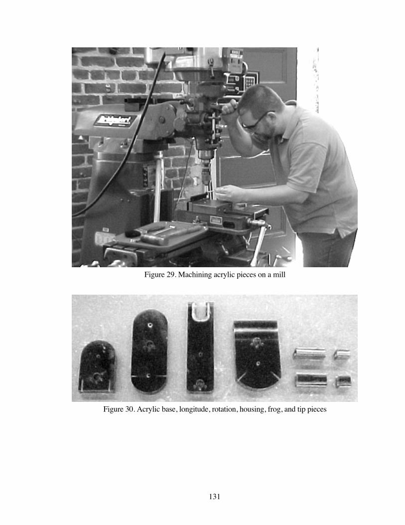
131
Figure 29. Machining acrylic pieces on a mill
Figure 30. Acrylic base, longitude, rotation, housing, frog, and tip pieces

132
Figure 31. Turning aluminum capstans on a lathe
Figure 32. Aluminum capstans

133
BIBLIOGRAPHY
Abbott, C. 1982. Remembering performance gestures. In Proceedings of the International
Computer Music Conference, Venedig, 188-193.
Abele, H. 1905. The violin and its story: History and construction of the violin. Translated
by G. Alwyn. London: E. Shore.
Adler, S. 1982. The study of orchestration. New York: W. W. Norton and Company.
Adrien, J. and X. Rodet. 1995. Physical models of instruments: A modular approach,
application to strings. In Proceedings of the International Computer Music Conference,
Burnaby, 85-89.
Adrien, J., R. Causse, and E. Ducasse. 1988. Dynamic modeling of stringed and wind
instruments: Sound synthesis by physical models. In Proceedings of the International
Computer Music Conference, Cologne, 265-276.
Appleton, J. 1984. Live and in concert: Composer/performer views of real-time performance
systems. Computer Music Journal 8 (1): 48-51.
Appleton, J. 1986. The computer and live musical performance. In Proceedings of the
International Computer Music Conference, The Hague, 321-326.
Askenfelt, A. 1986. Measurement of bow motion and bow force in violin playing. Journal
of the Acoustical Society of America 80 (4): 1007-1015.
Askenfelt, A. 1989. Measurement of the bowing parameters in violin playing. II: Bow-
bridge distance, dynamic range, and limits of bow force. Journal of the Acoustical Society of
America 86 (2): 503-516.
Askenfelt, A. and E. V. Jansson. 1992. On vibration sensation and finger touch in stringed
instrument playing. Music Perception 9 (3): 311-350.
134
Avanzini, F. and D. Rocchesso. 2001. Controlling material properties in physical models of
sounding objects. In Proceedings of the International Computer Music Conference,
Havana, 91-94.
Auer, L. 1921. Violin playing: As I teach it. New York: Frederick A. Stokes Company.
Babitz, S. 1970. Differences between 18th century and modern violin bowing. Los Angeles:
Early Music Laboratory.
Baillot, P. 1991. The art of the violin. Edited and translated by L. Goldberg. Evanston:
Northwestern University Press. Original edition, Paris: Dépôt Central de la Musique, 1835.
Belkin, A. 1991. Who’s playing? The computer’s role in musical performance. In
Proceedings of the International Computer Music Conference, Montreal, 131-134.
Bongers, B. 1994. The use of active tactile and force feedback in timbre controlling
electronic instruments. In Proceedings of the International Computer Music Conference,
Aarhus, 171-174.
Borin, G. G. De Poli, and A. Sarti. 1992. Algorithms and structures for synthesis using
physical models. Computer Music Journal 16 (4): 30-42.
Boulanger, R. 1986. Toward a new age of performance: Reading the "Book of Dreams"
with the Mathews electronic violin. Perspectives of New Music 24 (2): 130-155.
Boulanger, R. 1990. Conducting the MIDI orchestra, part 1: interviews with Max Mathews,
Barry Vercoe, and Roger Dannenberg. Computer Music Journal 14 (2): 34-46.
Boulanger, R., and M. Mathews. 1997. The 1997 Mathews radio-baton and improvisation
modes. In Proceedings of the International Computer Music Conference, Thessaloniki.
Boulanger, R., P. Smaragdis, and J. ffitch. 2000. Scanned synthesis: an introduction and
demonstration of a new synthesis and signal processing technique. In Proceedings of the
International Computer Music Conference, Berlin, 372-375.
135
Bowler, I., P. Manning, A. Purvis, and N. Bailey. 1990. On mapping N articulation on to M
synthesiser-control parameters. In Proceedings of the International Computer Music
Conference, Glasgow, 181-184.
Boyden, D. 1975. The history of violin playing from its origins to 1761 and its relationship
to the violin and violin music. London: Oxford University Press.
Bradley, J. 1976. Effect of bow force and speed on violin response. Journal of the
Acoustical Society of America 60 (1): 274-275.
Bradley, J. and T. Stewart. 1970. Comparison of violin response curves produced by hand
bowing, machine bowing and an electromagnetic driver. Journal of the Acoustical Society of
America 48 (2, 2): 575-578.
Brown, C., J. Bischoff, and T. Perkins. 1996. Bringing digital music to life. Computer
Music Journal 20 (2): 28-32.
Burtner, M. 2002. The Metasaxophone: concept, implementation, and mapping strategies
for a new computer music instrument. Organised Sound 7 (2): 201-213.
Burtner, M. and S. Serafin. 2002. The Exbow MetaSax: compositional applications of
bowed string physical models using instrument controller substitution.
Cadoz, C. 1988. Instrumental gesture and musical composition. In Proceedings of the
International Computer Music Conference, Cologne, 1-12.
Cadoz, C., J. Florens., and A. Luciani. 1995. Musical sounds, animated images with
CORDIS-ANIMA and its multimodal interfaces. In Proceedings of the International
Computer Music Conference, Banff, 531-532.
Cadoz, C., L. Lisowski, and J. Florens. 1990. A modular feedback keyboard design.
Computer Music Journal 14 (2): 47-51.
Cadoz, C., A. Luciani, and J. Florens. 1984. Responsive input devices and sound synthesis
by simulation of instrumental mechanisms: The Cordis system. Computer Music Journal 8
(3): 60-73.
136
Cadoz, C., A. Luciani, and J. Florens. 1993. CORDIS-ANIMA: A modeling and simulation
system for sound and image synthesis – The general formalism. Computer Music Journal
17 (1): 19-29.
Cadoz, C., A. Luciani, and J. Florens. 1994. Physical models for music and animated image:
The use of CORDIS-ANIMA in "ESQUISSES" a music film by ACROE. In Proceedings
of the International Computer Music Conference, Aarhus, 11-18.
Cadoz, C., A. Luciani, J. Florens, and T. Dars-Berberyan. 1982. The control channels of
instrumental playing in computer music: real time in computer music, incidence on the basic
models. In Proceedings of the International Computer Music Conference, Venedig, 73-91.
Canazza, S., A. Rodà, and N. Orio. 1999. A parametric model of expressiveness in musical
performance based on perceptual and acoustic analyses. In Proceedings of the International
Computer Music Conference, Beijing, 379-382.
Canazza, S., G. De Poli, G. Di Sanzo, and A. Vidolin. 1998. A model to add expressiveness
to automatic musical performance. In Proceedings of the International Computer Music
Conference, Ann Arbor, 163-170.
Canazza, S., G. De Poli, A. Rodà, and A. Vidolin. 1997. Analysis by synthesis of the
expressive intentions in musical performance. In Proceedings of the International
Computer Music Conference, Thessaloniki, 113-120.
Canazza, S., G. De Poli, R. Di Federico, C. Drioli, and A. Rodà. 1999. Expressive
processing of audio and MIDI performances in real time. In Proceedings of the
International Computer Music Conference, Beijing, 425-428.
Cariou, B. 1992. Design of an alternative controller from an industrial design perspective. In
Proceedings of the International Computer Music Conference, San Jose, 366-367.
Chabot, X. 1985. User software for realtime input by a musical instrument. In Proceedings
of the International Computer Music Conference, Burnaby, 19-23.

137
Chabot, X. 1990. Gesture interfaces and a software toolkit for performance with electronics.
Computer Music Journal 14 (2): 15-27.
Chadabe, J. 1983. Interactive composing: An overview. In Proceedings of the International
Computer Music Conference, Rochester, 298-306.
Chadabe, J. 1984. Interactive composing: An overview. Computer Music Journal 8 (1): 22-
27.
Chafe, C. 1989. Simulating performance on a bowed instrument. Chapter 15 of Current
directions in computer music research, ed. M. Mathews and J. Pierce, 185-198.
Cambridge: MIT Press.
Chafe, C. 1993. Tactile audio feedback. In Proceedings of the International Computer
Music Conference, Tokyo, 76-79.
Chafe, C. 2003. Communication by email with Charles Nichols. March 5.
Chafe, C. and S. O’Modhrain. 1996. Musical muscle memory and the haptic display of
performance nuance. In Proceedings of the International Computer Music Conference,
Hong Kong, 428-431.
Chen, E. and S. Team. 1999. Six degree-of-freedom haptic system for desktop virtual
prototyping applications. www.sensable.com/haptics/community/pdf/6dof_Laval.pdf.
Choi, I., R. Bargar, and C. Goudeseune. 1995. A manifold interface for a high dimensional
control space. In Proceedings of the International Computer Music Conference, Banff,
385-392.
Chu, L. 1996. Haptic feedback in computer music performance. In Proceedings of the
International Computer Music Conference, Hong Kong, 57-58.
Chu, L. 1999. MusiCloth: A Design Methodology for the Development of a Performance
Interface. In Proceedings of the International Computer Music Conference, Beijing.
138
Chu, L. 2002a. User Performance and Haptic Design Issues for a Force-Feedback Sound
Editing Interface. In Extended Abstracts of the Conference on Human Factors in
Computing Systems, Minneapolis.
Chu, L. 2002b. Haptic Design for Digital Audio. In Proceedings of the IEEE International
Conference on Multimedia and Expo, Lausanne.
Cook, P. 1995. A hierarchical system for controlling synthesis by physical modeling. In
Proceedings of the International Computer Music Conference, Banff, 108-109.
Cook, P. and G. Scavone. 1999. The Synthesis ToolKit (STK). In Proceedings of the
International Computer Music Conference, Beijing, 164-166.
Couturier, J. 2002. A scanned synthesis virtual instrument. In Proceedings of the
International Conference on New Interfaces for Musical Expression, Dublin, 176-178.
Cremer, L. 1972. The influence of "bow pressure" on the movement of a bowed string: Part
I. Catgut Acoustical Society Newsletter 18: 13-19.
Cremer, L. 1973. The influence of "bow pressure" on the movement of a bowed string: Part
II. Catgut Acoustical Society Newsletter 19: 21-25.
Cremer, L. 1982. Consideration of the duration of transients in bowed instruments. Catgut
Acoustical Society Newsletter 38: 13-18.
Cremer, L. 1984. The physics of the violin. Translated by J. Allen. Cambridge: MIT Press.
Original edition, Stuttgart: S. Hirzel Verlag, 1981.
De Laubier, S. 1998. The Meta-Instrument. Computer Music Journal 22 (1): 25-29.
De Loye, M. 1982. Real time control system for digital synthesizer. In Proceedings of the
International Computer Music Conference, Venedig, 241-244.
Djoharian, P. 2000. Shape and material design in physical modeling sound synthesis. In
Proceedings of the International Computer Music Conference, Berlin, 38-45.
139
Dodge, C. and T. Jerse. 1997. Real-time performance of computer music. Chapter 12 of
Computer music: Synthesis, composition, and performance, 402-428. New York: Schirmer
Books.
Eaglestone, B. 1988. A database environment for musician-machine interaction
experimentation. In Proceedings of the International Computer Music Conference,
Cologne, 20-27.
Emmerson, S. 1991. Computers and live electronic music: Some solutions, many problems.
In Proceedings of the International Computer Music Conference, Montreal, 135-138.
Favreau, E., M. Fingerhut, O. Koechlin, P. Potacsek, M. Puckette, R. Rowe. 1986. Software
developments for the 4X real-time system. In Proceedings of the International Computer
Music Conference, The Hague, 369-373.
Fletcher, N. and T. Rossing. 1998. Bowed string instruments. Chapter 10 of The physics of
musical instruments, 272-330. New York: Springer.
Florens, J., and C. Cadoz. 1990. Modular modelisation and simulation of the instrument. In
Proceedings of the International Computer Music Conference, Glasgow, 75-78.
Florens, J. and C. Henry. 2001. Bowed string synthesis with force feedback gesture
interaction. In Proceedings of the International Computer Music Conference, Havana, 115-
118.
Florens, J., C. Cadoz, and A. Luciani. 1998. A real-time workstation for physical model of
multi-sensorial and gesturally controlled instrument. In Proceedings of the International
Computer Music Conference, Ann Arbor, 518-526.
Florens, J., A. Razafindrakoto, A. Luciani, and C. Cadoz. 1986. Optimized real time
simulation of objects for musical synthesis and animated image synthesis. In Proceedings
of the International Computer Music Conference, The Hague, 65-70.
Frost, B. and B. Richardson. 1976. Tactile localization of sounds: Acuity, tracking moving
sources, and selective attention. Journal of the of the Acoustical Society of America 59 (4):
907-914.

140
Galamian, I. 1978. Principles of violin playing and teaching. Englewood Cliffs: Prentice-
Hall.
Garnett, G. and C. Goudeseune. 1999. Performance factors in control of high-dimensional
spaces. In Proceedings of the International Computer Music Conference, Beijing, 268-271.
Garnett, G. 2001. The aesthetics of interactive computer music. Computer Music Journal
25 (1): 21-33.
Garton, B. 1992. Virtual performance modelling. In Proceedings of the International
Computer Music Conference, San Jose, 219-222.
Geminiani, F. 1751. The art of playing on the violin. Edited by D. Boyden. London:
Oxford University Press.
Gescheider, G. 1970. Some comparisons between touch and hearing. IEEE Transactions
on Man-Machine Systems March 1970: 28-35.
Gescheider, G., L. Sager, and L. Ruffolo. 1975. Simultaneous auditory and tactile
information processing. Perception and Psychophysics 18 (3): 209-216.
Gibet, S. and J. Florens. 1988. Instrumental gesture modeling by identification with time-
varying mechanical models. In Proceedings of the International Computer Music
Conference, Cologne, 28-40.
Gillespie, B. 1992a. Dynamical modeling of the grand piano action. In Proceedings of the
International Computer Music Conference, San Jose, 447-448.
Gillespie, B. 1992b. The touchback keyboard. In Proceedings of the International
Computer Music Conference, San Jose, 447-448.
Gillespie, B. 1994. The virtual piano action: Design and implementation. In Proceedings of
the International Computer Music Conference, Aarhus, 167-170.
141
Gillespie, B. 1996. Haptic display of systems with changing kinematic constraints: The
virtual piano action. Ph.D. dissertation, Stanford University.
Goebel, J. 1988. Man-machine interaction. In Proceedings of the International Computer
Music Conference, Cologne, 41-48.
Graesser, H. 1998. Electric violins: Design and technique of electric bowed stringed
instruments. Frankfurt: Verlag Erwin Bochinsky.
Guettler, K. 1992. The bowed string computer simulated: Some characteristic features of the
attack. Catgut Acoustical Society Journal 2 (2): 22-26.
Gunther, E., G. Davenport, and S. O’Modhrain. 2002. Cutaneous grooves: Composing for
the sense of touch. In Proceedings of the International Conference on New Interfaces for
Musical Expression, Dublin, 37-42.
Hart, G. 1978. The violin: Its famous makers and their imitators. New York: AMS Press.
Original edition, London: Dulau, 1885.
Hayward, V. 2000. Haptics: A key to fast paced interactivity. In Human Friendly
Mechatronics: Selected Papers of the International Conference on Machine Automation,
Osaka.
Hayward, V. and B. Armstrong. 2000. A new computational model of friction applied to
haptic rendering. In Experimental Robotics VI, ed. P. Corke and J. Trevelyan, 404-412.
New York: Springer.
Hayward, V., J. Choksi, G. Lanvin, and C. Ramstein. 1994. Design and multi-objective
optimization of a linkage for a haptic interface. In Advances in Robot Kinematics, ed. J.
Lenarcic and B. Ravani, 352-359. Kluwer Academic.
Hirano, K. 1996. A review of electronic music instruments. Computer Music Journal 20
(3): 28-30.
Hodgson, P. 1958. Motion study and violin bowing. Urbana: American String Teachers
Association.
142
Horenstein, S. 1995. Interactive works: new problems and potentials. In Proceedings of the
International Computer Music Conference, Banff, 164-166.
Hunt, A., M. Wanderley, and R. Kirk. 2000. Towards a model for instrumental mapping in
expert musical interaction. In Proceedings of the International Computer Music
Conference, Berlin, 209-212.
Hunt, A., M. Wanderley, and M. Paradis. 2002. The importance of parameter mapping in
electronic instrument design. In Proceedings of the International Conference on New
Interfaces for Musical Expression, Dublin, 149-154.
Hutchins, C. 1962. The physics of violins. Scientific American
Incerti, E. and C. Cadoz. 1995. Topology, geometry, matter of vibrating structures simulated
with CORDIS-ANIMA. Sound synthesis methods. In Proceedings of the International
Computer Music Conference, Banff, 96-103.
Jaffe, D. 1995. Ten criteria for evaluating synthesis techniques. Computer Music Journal
19 (1): 76-87.
Jaffe, D. and A. Schloss. 1992. The making of "Wildlife." In Proceedings of the
International Computer Music Conference, San Jose, 269-272.
Jaffe, D. and A. Schloss. 1994. The computer-extended ensemble. Computer Music
Journal 18 (2): 78-86.
Jaffe, D. and J. Smith. 1995. Performance expression in commuted waveguide synthesis of
bowed strings. In Proceedings of the International Computer Music Conference, Banff,
343-346.
Joachim, J. 1905. Violin School: I. Instructions for beginners. Berlin: N. Simrock.
Kimura, M. 1995. Performance practice in computer music. Computer Music Journal 19
(1): 64-75.
143
Kitner, M. and A. Reblitz. 1984. The Mills Violano-Virtuoso: ...the famous self-playing
violin and piano ...how it works, how to service and rebuild it, together with a fascinating
collection of previously unpublished pictures concerning its history, its inventor, and its
manufacturer. Vestal: Vestal Press.
Klatzky, R. and S. Lederman. 1987. The intelligent hand. Psychology of Learning and
Motivation 21: 121-151.
Kolneder, W. 1998. The Amadeus book of the violin: Construction, history, and music.
Translated and edited by R. Pauly. Portland: Amadeus Press.
Kohut, J. and M. Mathews. 1971. Study of motion of a bowed violin string. Journal of the
Acoustical Society of America 49 (2): 532-537.
Lawergren, B. 1980. On the motion of bowed violin strings. Acustica 44 (3): 194-206.
Leipp, E. 1969. The violin: History, aesthetics, manufacture, and acoustics. Translated by
H. Parry. Toronto: University of Toronto Press.
Lindemann, E., F. Dechelle, B. Smith, and M. Starkier. 1991. The architecture of the
IRCAM musical workstation. Computer Music Journal 15 (3): 41-49.
Lippe, C. 1996. A look at performer/machine interaction using real-time systems. In
Proceedings of the International Computer Music Conference, Hong Kong, 116-117.
Loy, G. 1985. Designing an operating environment for a realtime performance processing
system. In Proceedings of the International Computer Music Conference, Burnaby, 9-13.
MacDonald, A. 1995. Performance practice in the presentation of electroacoustic music.
Computer Music Journal 19 (4): 88-92.
Machover, T. 1992. Hyperinstruments: A composer’s approach to the evolution of
intelligent musical instruments. In Cyberarts: Exploring art and technology, ed. L.
Jacobson, 67-76. San Francisco: Miller Freeman.
144
Machover, T. and J. Chung. 1989. Hyperinstruments: Musically intelligent and interactive
performance and creativity systems. In Proceedings of the International Computer Music
Conference, Columbus, 186-190.
Malouf, F., M. Lentczner, and C. Chafe. 1990. A real-time implementation of physical
models. In Proceedings of the International Computer Music Conference, Glasgow, 191-
193.
Manning, P. 1993. Electronic and Computer Music. Oxford: Oxford University Press.
Mathews, M. 1984. Electronic violin: A research tool. Journal of the Violin Society of
America 8 (1): 71-88.
Mathews, M. 1988. Pickups for the vibrations of violin and guitar strings using
piezoelectric bimorphic bender elements. Technical Report STAN-M-54. Stanford
University, Department of Music, Center for Computer Research in Music and Acoustics.
Mathews, M. 1989a. The conductor program and mechanical baton. In Current Directions
in Computer Music Research, eds. M. Mathews and J. Pierce, 263-281. Cambridge: The
MIT Press.
Mathews, M. 1989b. Bimorphic piezoelectric pickup device for stringed musical
instruments. United States Patent 4,860,625.
Mathews, M. 1991. The radio baton and conductor program, or: pitch, the most important
and least expressive part of music. Computer Music Journal 15 (4): 37-46.
Mathews, M. 2000. Radio-baton instruction manual. MARMAX.
Mathews, M. and J. Kohut. 1973. Electronic simulation of violin resonances. Journal of the
Acoustical Society of America 53 (6): 1620-1626.
Mathews, M. and F. Moore. 1970. GROOVE – a program to compose, store, and edit
functions of time. Communications of the ACM 13 (12): 715-721.

145
Mathews, M. and J. Pierce. 1987. The computer as a musical instrument. Scientific
American 255 (2): 126-133.
McIntyre, M. and J. Woodhouse. 1979. On the fundamentals of bowed-string dynamics.
Acustica 43 (2): 93-108.
McIntyre, M., R. Schumacher, and J. Woodhouse. 1977. New results on the bowed string.
Catgut Acoustical Society Newsletter 28: 27-31.
McIntyre, M., R. Schumacher, and J. Woodhouse. 1981. Aperiodicity in bowed-string
motion. Acustica 49 (1): 13-32.
McIntyre, M., R. Schumacher, and J. Woodhouse. 1982. Aperiodicity in bowed- string
motion: on the differential-slipping mechanism. Acustica 50 (4): 294-295.
McIntyre, M., R. Schumacher, and J. Woodhouse. 1983. On the oscillations of musical
instruments. Journal of the Acoustical Society of America 74 (5): 1325-1345.
Metlay, M. 1990. The musician-machine interface to MIDI. Computer Music Journal 14
(2): 73-83.
Moore, R. 1987. The dysfunctions of MIDI. In Proceedings of the International Computer
Music Conference, Champaign/Urbana, 256-263.
Morse, P. 1981. The flexible string. Chapter 3 of Vibration and sound, 71-150. Acoustical
Society of America.
Mozart, L. 1951. A treatise on the fundamental principles of violin playing. Translated by
E. Knocker. London: Oxford University Press. Original edition, Augsburg: Johann Jacob
Lotter, 1756.
Négyesy, J. and L. Ray. 1989. Zivatar: A performance system. Chapter 20 of Current
directions in computer music research, ed. M. Mathews and J. Pierce, 283-289.
Cambridge: MIT Press.
146
Neubert, D. 1982-83. Electronic bowed string works: Some observations on trends and
developments in the instrumental/electronic medium. Perspectives of New Music 21: 540-
566.
Nichols, C. 2000. The vBow: A haptic musical controller human-computer interface. In
Proceedings of the International Computer Music Conference, Berlin, 274-276.
Nichols, C. 2001a. The vBow: Haptic feedback and sound synthesis of a virtual violin bow
controller. Journal of the Society for Electro-Acoustic Music in the United States 16 (1): 5-
9.
Nichols, C. 2001b. The vBow: Two versions of a virtual violin bow controller. In
Proceedings of the International Symposium of Musical Acoustics, Perugia, 263-266.
Nichols, C. 2002. The vBow: Development of a virtual violin bow haptic human-computer
interface. In Proceedings of the International Conference on New Interfaces for Musical
Expression, Dublin, 29-32.
O’Modhrain, S. 1997. Feel the music: Narration in touch and sound. In Proceedings of the
International Computer Music Conference, Thessaloniki, 321-324.
O’Modhrain, S. 2000. Playing by feel: Incorporating haptic feedback into computer-based
musical instruments. Ph.D. dissertation, Stanford University.
O’Modhrain, S. and C. Chafe. 2000a. Incorporating haptic feedback into interfaces for
music applications. In Proceedings of the International Symposium on Robotics with
Applications, World Automation Conference, Maui.
O’Modhrain, S. and C. Chafe. 2000b. The performer-instrument interaction: a sensory
motor perspective. In Proceedings of the International Computer Music Conference, Berlin,
145-148.
O’Modhrain, S. and B. Gillespie. 1995a. The Moose: A haptic user interface for blind
persons. Report No. STAN-M-95, Center for Computer Research in Music and Acoustics,
Department of Music, Stanford University.
147
O’Modhrain, S. and B. Gillespie. 1995b. The Moose: A haptic interface for the digital
sound studio. Report No. STAN-M-95, Center for Computer Research in Music and
Acoustics, Department of Music, Stanford University.
O’Modhrain, S., S. Serafin, C. Chafe, and J. Smith. 2000. Qualitative and quantitative
assessment on the playability of a virtual bowed string instrument. In Proceedings of the
International Computer Music Conference, Berlin, 66-69.
Oppenheim, D. 1986. The need for essential improvements in the machine-composer
interface used for the composition of electroacoustic computer music. In Proceedings of the
International Computer Music Conference, The Hague, 443-445.
Oppenheim, D. 1992. Compositional tools for adding expression to music in DMIX. In
Proceedings of the International Computer Music Conference, San Jose, 223-226.
Oppenheim, D., and J. Wright. 1996. Towards a framework for handling musical
expression. In Proceedings of the International Computer Music Conference, Hong Kong,
71-74.
Orio, N., N. Schnell, and M. Wanderley. 2001. Input devices for musical expression:
Borrowing tools from HCI. In Proceedings of the Workshop on New Interfaces for
Musical Expression, Conference on Human Factors in Computing Systems, Seattle.
Paradiso, J. 1997. Electronic music: New ways to play. IEEE Spectrum 34 (12): 18-30.
Paradiso, J. and N. Gershenfeld. 1997. Musical applications of electric field sensing.
Computer Music Journal 21 (2): 69-89.
Pennycook, B. 1985. Computer-music interfaces: A survey. Computing Surveys 17 (2):
267-288.
Pickering, C. 1991. The bowed string. Mattituck: Amereon.
Piston, W. 1955. Orchestration. New York: W. W. Norton and Company.
148
Pope, S., ed. 1995. Touched by machine? – Composition and performance in the digital age.
Computer Music Journal 19 (3): 13-17.
Pressing, J. 1990. Cybernetic issues in interactive performance systems. Computer Music
Journal 14 (1): 12-25.
Pressing, J. 1992. Nonkeyboard controllers. Chapter 9 of Synthesizer performance and
real-time techniques, 375-389. Madison: A-R Editions.
Puckette, M. and Z. Settel. 1993. Nonobvious roles for electronics in performance
enhancement. In Proceedings of the International Computer Music Conference, Tokyo,
134-137.
Raman, C. 1920-21. II. – Experiments with mechanically-played violins. In Proceedings of
the Indian Association for the Cultivation of Science 6: 19-36.
Ramstein, C. and V. Hayward. 1994. The PANTOGRAPH: A large workspace haptic
device for a multi-modal human-computer interaction. In Proceedings of the Conference on
Human Factors in Computing Systems, Boston.
Richardson, B. and B. Frost. 1979. Tactile localization of the direction and distance of
sounds. Perception and Psychophysics 25 (4): 336-344.
Riddell, A. 1993. Composing the interface. Ph.D. dissertation, Princeton University.
Roads, C. 1980. Interview with Max Mathews. Computer Music Journal 4 (4): 15-22.
Roads, C. 1996. Musical input devices. Chapter 14 of The computer music tutorial, 617-
658. Cambridge: MIT Press.
Robles-De-La-Torre, G. and V. Hayward. 2000. Virtual surfaces and haptic shape
perception. In Proceedings of the Symposium on Haptic Interfaces for Virtual Environment
and Teleoperator Systems, American Society of Mechanical Engineers International
Mechanical Engineering Congress and Exposition, Orlando.
149
Robinson, C. 1987. Real time synthesis of bowed string timbres. In Proceedings of the
International Computer Music Conference, Champaign/Urbana, 125-129.
Rodet, X. and C. Vergez. 1999. Nonlinear dynamics in physical models: Simple feedback-
loop systems and properties. Computer Music Journal 23 (3): 18-34.
Rodet, X. and C. Vergez. 1999. Nonlinear dynamics in physical models: From basic models
to true musical-instrument models. Computer Music Journal 23 (3): 35-49.
Rose, J. 2003. http://www.jonroseweb.com/.
Rovan, J. and V. Hayward. 2000. Typology of tactile sounds and their synthesis in gesture-
driven computer music performance. In Trends in Gesture Control of Music, ed. M.
Wanderley and M. Battier. Paris: Editions IRCAM.
Rovan, J., M. Wanderley, S. Dubnov, and P. Depalle. 1997. Instrumental gestural mapping
strategies as expressivity determinants in computer music performance. In Proceedings of
KANSEI – The Technology of Emotion Workshop, Genova.
Rowe, R. 1993. Interactive music systems: Machine listening and composing. Cambridge:
MIT Press.
Rubine, D. and P. McAvinney. 1990. Programmable finger-tracking instrument controllers.
Computer Music Journal 14 (1): 26-41.
Sadie, S., ed. 1980. The New Grove dictionary of music and musicians. London:
Macmillan Publishers.
Sandys, W. 1864. The history of the violin, and other instruments played on with the bow
from the remotest times to the present. London: John Russell Smith.
Sasaki, L., G. Fedorkow, W. Buxton, C. Retterath, and K. Smith. 1981. A touch-sensitive
input device. In Proceedings of the International Computer Music Conference, Denton,
293-297.
150
Saunders, F. 1937. The mechanical action of violins. Journal of the Acoustical Society of
America 9: 81-98.
Schelleng, J. 1963. The violin as a circuit. Journal of the Acoustical Society of America 35
(3): 326-338.
Schelleng, J. 1973. The bowed string and the player. Journal of the Acoustical Society of
America 53 (1): 26-41.
Schiemer, G. and B. Krishnakumar. 1996. Appropriated musical instruments: A4 MIDI
Tool Box and Carnatic violin. In Proceedings of the International Computer Music
Conference, Hong Kong, 177-180.
Schloss, A. and D. Jaffe. 1993. Intelligent musical instruments: The future of musical
performance or the demise of the performer? INTERFACE Journal for New Music
Research 22 (3): 183-193.
Schoner, B., C. Cooper, and N. Gershenfeld. 2000. Cluster-weighted sampling for
synthesis and cross-synthesis of violin family instruments. In Proceedings of the
International Computer Music Conference, Berlin, 376-379.
Schoner, B., C. Cooper, C. Douglas, and N. Gershenfeld. 1998. Data-driven modeling and
synthesis of acoustical instruments. In Proceedings of the International Computer Music
Conference, Ann Arbor, 66-73.
Schumacher, R. 1975. Some aspects of the bow. Catgut Acoustical Society Newsletter 24:
5-8.
Schumacher, R. 1979. Self-sustained oscillations of the bowed string. Acustica 43 (2): 109-
120.
Schumacher, R. 1994. Measurements of some parameters of bowing. Journal of the
Acoustical Society of America 96 (4): 255-268.
Seagrave, B. and J. Berman. 1976. Dictionary of Bowing Terms for Stringed Instruments.
American Teachers Association.
151
Serafin, S. and J. Smith. 2000. Influence of attack parameters on the playability of a virtual
bowed string instrument. In Proceedings of the International Computer Music Conference,
Berlin, 473-476.
Serafin, S., J. Smith, and J. Woodhouse. 1999. An investigation of the impact of torsion
waves and friction characteristics on the playability of virtual bowed strings. In Proceedings
of the IEEE Workshop on Application of Signal Processing to Audio and Acoustics, New
Paltz.
Serafin, S., C. Vergez, and X. Rodet. 1999. Friction and application to real-time physical
modeling of a violin. In Proceedings of the International Computer Music Conference,
Beijing, 216-219.
Serafin, S., M. Burtner, C. Nichols, and S. O’Modhrain. 2001. Expressive controllers for
bowed string physical models. In Proceedings of the COST G-6 Conference on Digital
Audio Effects, Limerick.
Serafin, S., R. Dudas, M. Wanderley, and X. Rodet. 1999. Gestural control of a real-time
physical model of a bowed string instrument. In Proceedings of the International Computer
Music Conference, Beijing, 375-378.
Serafin, S., P. Huang, S. Ystad, C. Chafe, J. and Smith. 2002. Analysis and synthesis of
unusual friction-driven musical instruments. In Proceedings of the International Computer
Music Conference, Gothenborg.
Serafin, S., J. Smith, H. Thornburg, F. Mazzella, A. Tellier, and G. Thonier. 2001. Data
driven identification and computer animation of bowed string model. In Proceedings of the
International Computer Music Conference, Havana, 207-210.
Serafin, S. C. Wilkerson, and J. Smith. 2002. Modeling bowl resonators using circular
waveguide networks. In Proceedings of the COST G-6 Conference on Digital Audio Effects,
Hamburg.
Shibuya, K. and S. Sugano. 1997. A strategy for the finger-arm coordinated motion
analysis of human motion in violin playing. In Romansy 11: Theory and practice of robots
152
and manipulators: Proceedings of the Eleventh CISM-IFToMM Symposium, Udine, 259-
266.
Shibuya, K., Y. Chikaoka, T. Koyama, and S. Sugano. 1997. The planning of violin playing
robot with KANSEI information – Algorithm to decide bowing parameters from timbre. In
Proceedings of the 6th IEEE International Workshop on Robot and Human
Communication, Sendai, 230-235.
Shibuya, K., H. Tanabe, T. Asada, and S. Sugano. 1996. Construction of KANSEI model
for the planning of bowing in violin playing. In Proceedings of the 5th IEEE International
Workshop on Robot and Human Communication, Tsukuba, 422-427.
Sinkeviciute, B. and S. Sondeckis. 1986. On the identification of violin strokes in a real-
time performance system. In Proceedings of the International Computer Music Conference,
The Hague, 187-191.
Smith, J. 1982. Synthesis of bowed strings. In Proceedings of the International Computer
Music Conference, Venedig, 308-340.
Smith, J. 1986. Efficient simulation of the reed-bore and bow-string mechanisms. In
Proceedings of the International Computer Music Conference, The Hague, 275-280.
Smith. J. 1993. Efficient synthesis of stringed musical instruments. In Proceedings of the
International Computer Music Conference, Tokyo, 64-71.
Smith, J. 1996. Physical modeling synthesis update. Computer Music Journal 20 (2): 44-
56.
Smith, J. 1997. Nonlinear commuted synthesis of bowed strings. In Proceedings of the
International Computer Music Conference, Thessaloniki, 264-267.
Snell, J. 1983. Sensors for playing computer music with expression. In Proceedings of the
International Computer Music Conference, Rochester, 113-126.
Stoeving, P. 1904. The story of the violin. London: Walter Scott Publishing.
153
Takala, T., J. Hiipakka, M. Laurson, and V. Välimäki. 2000. An expressive synthesis model
for bowed string instruments. In Proceedings of the International Computer Music
Conference, Berlin, 70-73.
Ten Hoopen, C. 1992. Perceptual dilemmas of new computer music. In Proceedings of the
International Computer Music Conference, San Jose, 425-426.
Trueman, D. 1999. Reinventing the violin. Ph.D. dissertation, Princeton University.
Trueman, D. and P. Cook. 1999. BoSSA: The deconstructed violin reconstructed. In
Proceedings of the International Computer Music Conference, Beijing, 232-239.
Trueman, D. and P. Cook. 2000. BoSSA: The deconstructed violin reconstructed. Journal
of New Music Research 29 (2): 121-130.
Van Der Straeten, E. 1968. The history of the violin: Its ancestors and collateral
instruments from earliest times. New York: Da Capo Press. Original edition, London:
Butler and Tanner, 1933.
Verplank, B., M. Gurevich, and M. Mathews. 2002. The Plank: Designing a simple haptic
controller. In Proceedings of the International Conference on New Interfaces for Musical
Expression, Dublin, 33-36.
Verplank, B., M. Mathews, and R. Shaw. 2000. Scanned synthesis. In Proceedings of the
International Computer Music Conference, Berlin, 368-371.
Verrillo, R. 1992. Vibration sensation in humans. Music Perception 9 (3): 281-302.
Vertegaal, R., T. Ungvary, and M. Kieslinger. 1996. Towards a musician’s cockpit:
Transducers, feedback and musical function. In Proceedings of the International Computer
Music Conference, Hong Kong, 308-311.
Vertegaal, R., B. Eaglestone, and M. Clarke. 1994. An evaluation of input devices for use in
the ISEE human-synthesizer interface. In Proceedings of the International Computer Music
Conference, Aarhus, 159-162.

154
Voelkel, A. 1985. A cost effective input processor-pitch detector for electronic violin. In
Proceedings of the International Computer Music Conference, Burnaby, 15-17.
Wanderley, M. 1999. Non-obvious performer gestures in instrumental music. In Gesture-
Based Communication in Human-Computer Interaction, Proceedings of the International
Gesture Workshop, Gif-sur-Yvette.
Wanderley, M. 2001. Gestural control of music. In Proceedings of the International
Workshop on Human Supervision and Control in Engineering and Music, Kassel.
Wanderley, M., P. Depalle, and O. Warusfel. 1999. Improving instrumental sound
synthesis by modeling the effects of performer gesture. In Proceedings of the International
Computer Music Conference, Beijing, 418-421.
Wanderley, M., N. Schnell, and J. Rovan. 1998. ESCHER – Modeling and performing
composed instruments in real-time. In Proceedings of the IEEE Symposium on Systems,
Man, and Cybernetics, San Diego.
Wanderley, M., M. Serra, M. Battier, and X. Rodet. 2001. Gestural control at IRCAM. In
Proceedings of the International Computer Music Conference, Havana, 455-458.
Wanderley, M., J. Viollet, F. Isart, and X. Rodet. 2000. On the choice of transducer
technologies for specific musical functions. In Proceedings of the International Computer
Music Conference, Berlin, 244-247.
Wessel, D. 1991. Instruments that learn, refined controllers, and source model
loudspeakers. Computer Music Journal 15 (4): 82-86.
Winkler, T. 1995. Making motion musical: Gesture mapping strategies for interactive
computer music. In Proceedings of the International Computer Music Conference, Banff,
261-264.
Woodhouse, J. 1992. Physical modeling of bowed strings. Computer Music Journal 16
(4): 43-56.
155
Woodhouse, J. 1993a. On the playability of violins. Part I: Reflection functions. Acustica
78: 125-136.
Woodhouse, J. 1993b. On the playability of violins. Part II: Minimum bow force and
transients. Acustica 78: 137-153.
Young, D. 2002. The Hyperbow controller: Real-time dynamics measurement of violin
performance. In Proceedings of the International Conference on New Interfaces for
Musical Expression, Dublin, 65-70.
Young, D. and S. Serafin. 2003. Playability evaluation of a virtual bowed string instrument.
In Proceedings of the International Conference on New Interfaces for Musical Expression,
Montreal, 104-108.
Zimmerman, T., J. Smith, J. Paradiso, D. Allport, and N. Gershenfeld. 1995. Applying
electric field sensing to human-computer interfaces. In Proceedings of the Conference on
Human Factors in Computing Systems, Denver, 280-287.