The Use of Second Life Electric Vehicle Batteries for Grid ...
7
The Use of Second Life Electric Vehicle Batteries for Grid Support Gillian Lacey, Ghamin Putrus , Anwar Salim Northumbria University, Newcastle, UK [email protected] Abstract---Matching electrical power supply to customer demand is an on-going problem for electricity distribution network operators and it is increasing with the growth of distributed renewable energy generation at the low voltage (LV) level. A battery energy storage system (BESS) has been suggested which would help the control of voltage levels, optimise renewable generation and supply the evening peak demand. In addition a BESS could offer ancillary support to the network including balancing services as well as deferring network asset upgrade, with ensuing financial advantages. Until now the cost of providing a BESS has been prohibitive except for the most isolated and essential supply. The main contribution of this paper will be to demonstrate that afterlife electric vehicle (EV) batteries can be used in BESS for the provision of such services with particular emphasis on peak shaving and upgrade deferral. The size of the BESS is calculated using a simulation based on a LV load profile and the effect on voltage is modelled and displayed graphically. Considering that the market penetration of EVs has been hampered by high cost of Li-ion batteries and with projections of the first set of used automotive batteries becoming available from 2019 an investigation into the afterlife usage of EV batteries is timely and economic. Keywords: storage, second life batteries, grid support, Simulink model I. INTRODUCTION Matching power generation and demand is increasingly becoming one of the most challenging areas of the power industry. The inability to store electricity in large quantities has led to utilities constantly trying to match generation with consumption on a real time basis. Forecasting and some demand management goes some way to narrowing the gap, but uncertainty over wind generation and changing consumer profiles still exists. This variation in consumption presents a problem to utilities as the energy requirements during the peak which lasts just a few hours for the daily cycle and a few months for the annual cycle is substantially higher than the average power requirements of the network. This phenomenon makes it mandatory for utilities to design transmission and distribution systems sized for peak load requirements. This results in the network being under loaded for most of its operational life which is costly and quite wasteful. The use of additional generation with subsequent redundancy of system equipment is required to handle this uncertainty which increases the cost of generation. The ability to store and utilise significant amounts of energy on demand in power networks can defer system upgrades, increase power quality, buffer variable distributed generation and provide flexibility to utilities. There are many energy storage technologies for power systems. The most popular of these are pumped hydro storage, flywheel storage and battery energy storage systems (BESS). Of these technologies, the BESS stands out because of its power capacity and quick response time (20 milliseconds in some batteries) [1]. The main drawback to more widespread use of BESS is the cost. If cost issues can be overcome, energy storage systems will have multiple benefits which include deferral of system upgrade, optimisation of renewables and improving power quality [2]. Typically, lead acid batteries have been the major players in the power industry because of the maturity of the technology and ease of maintenance. However, most modern battery systems use lithium based batteries because of their higher energy density and very high storage efficiencies [3]. The most widespread use of lithium based batteries is in portable devices and electric vehicles (EVs). However, the high cost of these batteries prevents their use in BESS and is also a major impediment to the widespread take-up of EVs. A 2 nd life use for the car battery after degradation had deemed its capacity to be too low for driving, could make the overall cost of the EV more acceptable to the consumer. This has the added benefit of providing ancillary services to the grid to support a future market that will require cost effective energy storage to facilitate flexible generation and demand. [4]. Studies by Kempton & Tomi´c [5] have shown that ancillary services account for 5-10% of the cost of electricity. BESS can play a significant role in the provision of these ancillary services [3]. Another important role that BESS can play is in the deferral of upgrades to transformers and other transmission and distribution (T&D) assets as the peak demand can be shaved by meeting it with power which has been stored during times of lower demand or high renewable generation. The concept of peak shaving entails storing cheap baseload energy at off peak hours (in the troughs) and releasing it into the network during peak hours. Thus, the load profile of the network, storage efficiency of the storage medium and the tariff structure are the most important considerations in peak shaving. In a study by Pandiaraj et al [6], it is stated that optimal economic operation can only be achieved if reliable storage components that are reasonably priced are selected. These components must be designed such that they satisfy the issues for the network profile under consideration. Considering that the market penetration of EVs has been hampered by high cost of Li-Ion batteries and with projections of the first set of used automotive batteries becoming available from 2019 [1], an investigation into the afterlife usage of EV batteries is worthwhile for the EV purchaser and the Distribution Network Operator (DNO).
Transcript of The Use of Second Life Electric Vehicle Batteries for Grid ...

The Use of Second Life Electric Vehicle Batteries
for Grid Support Gillian Lacey, Ghamin Putrus
, Anwar Salim
Northumbria University, Newcastle, UK [email protected]
Abstract---Matching electrical power supply to customer
demand is an on-going problem for electricity distribution
network operators and it is increasing with the growth of
distributed renewable energy generation at the low voltage (LV)
level. A battery energy storage system (BESS) has been suggested
which would help the control of voltage levels, optimise
renewable generation and supply the evening peak demand. In
addition a BESS could offer ancillary support to the network
including balancing services as well as deferring network asset
upgrade, with ensuing financial advantages. Until now the cost of
providing a BESS has been prohibitive except for the most
isolated and essential supply. The main contribution of this
paper will be to demonstrate that afterlife electric vehicle (EV)
batteries can be used in BESS for the provision of such services
with particular emphasis on peak shaving and upgrade deferral.
The size of the BESS is calculated using a simulation based on a
LV load profile and the effect on voltage is modelled and
displayed graphically. Considering that the market penetration
of EVs has been hampered by high cost of Li-ion batteries and
with projections of the first set of used automotive batteries
becoming available from 2019 an investigation into the afterlife
usage of EV batteries is timely and economic.
Keywords: storage, second life batteries, grid support, Simulink
model
I. INTRODUCTION
Matching power generation and demand is increasingly
becoming one of the most challenging areas of the power
industry. The inability to store electricity in large quantities
has led to utilities constantly trying to match generation with
consumption on a real time basis. Forecasting and some
demand management goes some way to narrowing the gap,
but uncertainty over wind generation and changing consumer
profiles still exists.
This variation in consumption presents a problem to utilities
as the energy requirements during the peak which lasts just a
few hours for the daily cycle and a few months for the annual
cycle is substantially higher than the average power
requirements of the network. This phenomenon makes it
mandatory for utilities to design transmission and distribution
systems sized for peak load requirements. This results in the
network being under loaded for most of its operational life
which is costly and quite wasteful. The use of additional
generation with subsequent redundancy of system equipment
is required to handle this uncertainty which increases the cost
of generation.
The ability to store and utilise significant amounts of energy
on demand in power networks can defer system upgrades,
increase power quality, buffer variable distributed generation
and provide flexibility to utilities. There are many energy
storage technologies for power systems. The most popular of
these are pumped hydro storage, flywheel storage and battery
energy storage systems (BESS). Of these technologies, the
BESS stands out because of its power capacity and quick
response time (20 milliseconds in some batteries) [1]. The
main drawback to more widespread use of BESS is the cost. If
cost issues can be overcome, energy storage systems will have
multiple benefits which include deferral of system upgrade,
optimisation of renewables and improving power quality [2].
Typically, lead acid batteries have been the major players in
the power industry because of the maturity of the technology
and ease of maintenance. However, most modern battery
systems use lithium based batteries because of their higher
energy density and very high storage efficiencies [3]. The
most widespread use of lithium based batteries is in portable
devices and electric vehicles (EVs). However, the high cost of
these batteries prevents their use in BESS and is also a major
impediment to the widespread take-up of EVs. A 2nd
life use
for the car battery after degradation had deemed its capacity to
be too low for driving, could make the overall cost of the EV
more acceptable to the consumer. This has the added benefit
of providing ancillary services to the grid to support a future
market that will require cost effective energy storage to
facilitate flexible generation and demand. [4].
Studies by Kempton & Tomi´c [5] have shown that ancillary
services account for 5-10% of the cost of electricity. BESS
can play a significant role in the provision of these ancillary
services [3]. Another important role that BESS can play is in
the deferral of upgrades to transformers and other
transmission and distribution (T&D) assets as the peak
demand can be shaved by meeting it with power which has
been stored during times of lower demand or high renewable
generation.
The concept of peak shaving entails storing cheap baseload
energy at off peak hours (in the troughs) and releasing it into
the network during peak hours. Thus, the load profile of the
network, storage efficiency of the storage medium and the
tariff structure are the most important considerations in peak
shaving. In a study by Pandiaraj et al [6], it is stated that
optimal economic operation can only be achieved if reliable
storage components that are reasonably priced are selected.
These components must be designed such that they satisfy the
issues for the network profile under consideration.
Considering that the market penetration of EVs has been
hampered by high cost of Li-Ion batteries and with projections
of the first set of used automotive batteries becoming
available from 2019 [1], an investigation into the afterlife
usage of EV batteries is worthwhile for the EV purchaser and
the Distribution Network Operator (DNO).

II. NETWORK SUPPORT
A. The Issues
1) Peak shaving: Oudalov et al [7] state that power peak is
a relative term and as such, it requires a reference value. Any
value above the reference is referred to as a load peak. Using
the maximum power to be shaved and the duration of this
peak value which is the discharge time, the BESS capacity can
be determined using the formula below.
∫ (1)
Where Bcap = BESS capacity (Wh),
Bpw= Power (W) to be shaved
t = Time (hrs)
The use of BESS for peak shaving has an effect on the
system voltage. This is especially true on the LV side of the
network where there is a higher resistance than reactance and
as such, real power has a greater effect on voltage regulation
than reactive power. It can also have an effect on the system
frequency.
2) Voltage Control in Power Systems: Power utilities are
mandated to provide electricity to customers within a fixed
voltage range. Within the UK, this level is +10%/-6% of the
nominal voltage on the LV network [8]. At present, most
voltage control is carried out at high voltages (33kV and
higher) by OLTC (On Load Tap Changing) transformers and
devices that produce reactive power such as shunt capacitors
and reactors, synchronous condensers, static VAR
compensators (SVC) and static synchronous compensators
(STATCOM). This is due to the widespread use of induction
machines for electricity generation which always absorb
reactive power even when generating real power on
transmission lines.
To calculate the voltage at the end of the feeder:
(2)
Where: S = Apparent Power (VA),
P = Active Power (W),
Q = Reactive Power,
VR = Receiving end Voltage
It can be derived that
(3)
Generally,
(4)
So voltage drop is
(5)
And phase angle is
(6)
Where VS = Sending end Voltage, R = Line Resistance,
X = Line Reactance,
∆V = Voltage Drop, ∂V = Angular Shift
In transmission systems, the X/R ratio is normally high and
thus, the effect of line resistance may be ignored and voltage
regulation is determined largely by reactive power control [9].
In distribution circuits such as the network being considered
here, the effect of line resistance is higher than line reactance.
As such, the effect of active power on the voltage is
significant.
One of the problems presented by the rise in penetration of
DG into conventional power systems is due to the increase in
active power injected into the network by these sources. This
may cause the voltage at the point of common coupling (PCC)
to rise above the allowable upper limit [10], [11].
Additionally, intermittent generation from the DG will cause a
fluctuation in voltage that needs to be addressed in a timely
manner. The effects on voltage of peak shaving using BESS
may give an insight into how energy storage can be applied to
support voltage in distribution circuits.
3) Ancillary services: Energy storage can be integrated into
the National Grid to provide a number of services as discussed
below.
Ribeiro et al [12] highlighted rapid spinning reserve as a
service that can be provided by energy storage systems thus
substituting thermal units and combustion turbines that would
have been operating in reserve mode. This will reduce fuel
consumption – spinning reserve can use 10% of full power –
along with wear of generators, turbines and associated
equipment.
Reserves for frequency response are another possible
application of electrical energy supply (EES) as stated by
Parker [13]. Frequency responsive reserves counter-balance
fluctuations that exceed limitations in the system thus
providing frequency regulation.
In a study by Mohd et al [14] by utilizing energy surpluses
from off peak generation, peak demand can be supplied by the
EES at higher rates which provide added profits for utilities.
This short term operating reserve (STOR) is a service which
can be tendered for and payments received from the national
grid.
System instability which results from a lack of synchronism
of generators due to a phase difference between generation
and demand may cause system collapse. These are usually
caused by load disturbances. EES can be used to smooth the
load demand thereby ensuring synchronous network
operation.
Voltage regulation is usually provided by injection of
reactive power into the grid. Capacitors are conventionally
used to provide this service; however with the addition of
power electronics, BESS can be used to provide reactive
power during all periods of operation (Charging, discharging
and standby mode).
Upgrade deferral is a major application area for EES. T&D
upgrades arise due to the inability of existing infrastructure to
cater to peak demand conditions. Energy storage can be
placed at suitable points on the network in order to shave peak
demand and thus defer such upgrades.
Harmonic distortions, voltage sags and spikes cause
numerous problems to electronic equipment. Customers can

protect such equipment by utilizing EES. Reliability can also
be improved by using EES to provide bridging power (UPS)
for customers in order to ride through a power disruption
4) Renewable Energy: Integration of renewable energy into
the power grid gives rise to a number of difficulties due to the
fluctuating nature of most renewable sources. EES coupled
with renewable generation can help mitigate most of these
issues. The simulation shows how placing BESS at the same
voltage level as the distributed generation can counteract
issues such as voltage and frequency problems before they
cause problems outside the immediate vicinity.
B. The Battery Energy Storage System (BESS)
1) Location of the BESS in the network: It is expected
that there will be storage at every voltage level within
electricity networks in the future. The pictorial representation
of a possible future network is shown in Fig. 1
BESS is expected to play a significant role in these future
networks. These will consist of the BESS and a PCS
connected in parallel to a load. The BESS placed at the LV
can participate in peak shaving and help prevent power flow
into the transmission system from renewables.This is shown
in Fig. 2.
In order to appropriately install BESS within a particular
network, certain parameters need to be considered. These
include ratings for the components on the network in order to
size the particular BESS, possible impact of BESS on system
parameters such as load factor & diversity factor and
opportunities for T&D upgrade deferral.
2) Effect of location of BESS on load factor, diversity
factor and upgrade deferral: The load factor is a ratio of
average demand to theoretical maximum demand over a
period of time. The average demand is usually the power
consumed by a customer. This is given by:
∫ ( )
∫ ( )
(7)
∫ ( )
(8)
Sclabbach & Rofolski [15] give typical load factors for
different voltage levels as below:
TABLE I TYPICAL LOAD FACTORS
Voltage level Load factor
132kV 0.75 - 0.82
11kV & other MV systems 0.61 - 0.76
LV systems 0.50 - 0.77
Networks are usually designed to have high load factors
indicating that a group of loads operates near its peak most of
the time. This can however constitute a problem with
constantly expanding networks as the network can easily be
stretched beyond its limits prompting expensive T&D
upgrades. Strategic placement of BESS can defer such
upgrades for a significant amount of time. As can be seen
from table I, the LV network has less diversity and so a higher
variation of load factor than higher voltage levels. As such,
placement of the BESS at that level will ensure stable supply
and allow the batteries sufficient time to recharge during low
load conditions. Additionally, the effects of a system which
supplements the load or provides regulation from the LV end
of the network will reduce demand on the MV and HV side as
well.
Bulk GenerationG
Transmission Substation
Energy StorageEnergy Storage
Wind FarmPV Farm
To Distribution Substation
IndustrialEnergy Storage
FC LMLM EVPV
Energy Storage
LM
EV Car ParkPV
Distribution SubstationCommercial
330kV Transmission Line
132kV Transmission Line
11kV Distribution Line
33kV Distribution LineFC
FC
Residential
Transmission Substation
Fig. 1: A vision of future distribution networks
BESS
Tx Line
GRID
Load Bus
Load Profile
Shaved Profile
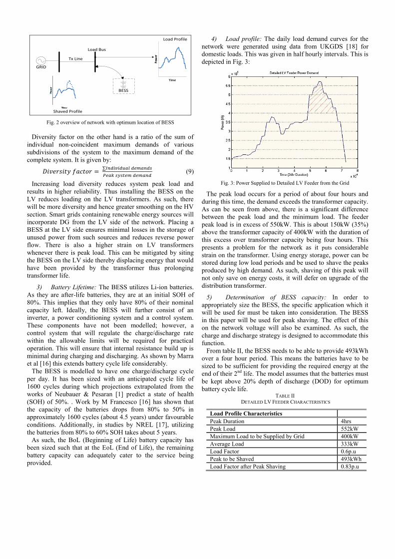
Fig. 2 overview of network with optimum location of BESS
Diversity factor on the other hand is a ratio of the sum of
individual non-coincident maximum demands of various
subdivisions of the system to the maximum demand of the
complete system. It is given by:
(9)
Increasing load diversity reduces system peak load and
results in higher reliability. Thus installing the BESS on the
LV reduces loading on the LV transformers. As such, there
will be more diversity and hence greater smoothing on the HV
section. Smart grids containing renewable energy sources will
incorporate DG from the LV side of the network. Placing a
BESS at the LV side ensures minimal losses in the storage of
unused power from such sources and reduces reverse power
flow. There is also a higher strain on LV transformers
whenever there is peak load. This can be mitigated by siting
the BESS on the LV side thereby displacing energy that would
have been provided by the transformer thus prolonging
transformer life.
3) Battery Lifetime: The BESS utilizes Li-ion batteries.
As they are after-life batteries, they are at an initial SOH of
80%. This implies that they only have 80% of their nominal
capacity left. Ideally, the BESS will further consist of an
inverter, a power conditioning system and a control system.
These components have not been modelled; however, a
control system that will regulate the charge/discharge rate
within the allowable limits will be required for practical
operation. This will ensure that internal resistance build up is
minimal during charging and discharging. As shown by Marra
et al [16] this extends battery cycle life considerably.
The BESS is modelled to have one charge/discharge cycle
per day. It has been sized with an anticipated cycle life of
1600 cycles during which projections extrapolated from the
works of Neubauer & Pesaran [1] predict a state of health
(SOH) of 50%. . Work by M Francesco [16] has shown that
the capacity of the batteries drops from 80% to 50% in
approximately 1600 cycles (about 4.5 years) under favourable
conditions. Additionally, in studies by NREL [17], utilizing
the batteries from 80% to 60% SOH takes about 5 years.
As such, the BoL (Beginning of Life) battery capacity has
been sized such that at the EoL (End of Life), the remaining
battery capacity can adequately cater to the service being
provided.
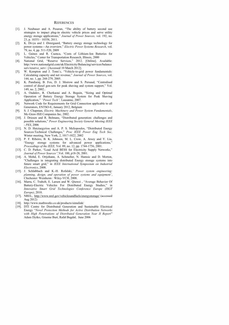
4) Load profile: The daily load demand curves for the
network were generated using data from UKGDS [18] for
domestic loads. This was given in half hourly intervals. This is
depicted in Fig. 3:
Fig. 3: Power Supplied to Detailed LV Feeder from the Grid
The peak load occurs for a period of about four hours and
during this time, the demand exceeds the transformer capacity.
As can be seen from above, there is a significant difference
between the peak load and the minimum load. The feeder
peak load is in excess of 550kW. This is about 150kW (35%)
above the transformer capacity of 400kW with the duration of
this excess over transformer capacity being four hours. This
presents a problem for the network as it puts considerable
strain on the transformer. Using energy storage, power can be
stored during low load periods and be used to shave the peaks
produced by high demand. As such, shaving of this peak will
not only save on energy costs, it will defer on upgrade of the
distribution transformer.
5) Determination of BESS capacity: In order to
appropriately size the BESS, the specific application which it
will be used for must be taken into consideration. The BESS
in this paper will be used for peak shaving. The effect of this
on the network voltage will also be examined. As such, the
charge and discharge strategy is designed to accommodate this
function.
From table II, the BESS needs to be able to provide 493kWh
over a four hour period. This means the batteries have to be
sized to be sufficient for providing the required energy at the
end of their 2nd
life. The model assumes that the batteries must
be kept above 20% depth of discharge (DOD) for optimum
battery cycle life. TABLE II
DETAILED LV FEEDER CHARACTERISTICS
Load Profile Characteristics
Peak Duration 4hrs
Peak Load 552kW
Maximum Load to be Supplied by Grid 400kW
Average Load 333kW
Load Factor 0.6p.u
Peak to be Shaved 493kWh
Load Factor after Peak Shaving 0.83p.u

Using these considerations, the required battery capacity is
obtained as shown below.
for a
duration of 4 hours. The batteries at the end of the 2nd
life
will have 50% of nominal capacity so nominal capacity must
be double that for end of life. In addition the batteries can only
discharge to 20%, meaning available capacity is 80%
(11)
Using the 2nd
life Nissan LEAF batteries as an example, with a
nominal capacity when new of 24kWh, this gives the number
of batteries as
(12)
The charge discharge profile showing the matching
load/storage area is shown in Fig. 4.
Fig. 4: Charge/discharge profile of BESS
III. A SIMULINK MODEL OF A LV ELECTRICITY NETWORK
A. Build a Simulink model of the network
A Simulink®
[18] representation of a detailed network was
built using data from an existing system and profiles from
UKGDS [19]. This is outlined in Fig. 5. Even though only
one LV feeder will be used for the scenarios, the network was
constructed from the 33kV down to the LV feeder in order to
see the effect of other branches of the network.
Include an afterlife EV Li-Ion BESS within the network and
determine the optimum location and size
Simulate and analyse the network performance with and
without Distributed Generators (DG).
Simulate and analyse the network performance with the BESS
used for peak shaving (with and without DG).
B. Evaluate the results obtained for an application of
second life Electric Vehicle batteries for grid support.
Four scenarios were modeled using the network and the
results for power demand and voltage variation within the
network were observed. The first scenario modeled the
network without any additions. The second scenario used the
BESS for peak shaving in the network. The third scenario
introduced Distributed Generators (DG); 100kW PV array and
a 100kW Wind Energy Conversion System (WECS) on the
detailed LV feeder. And finally, the fourth scenario looks at
the effect of using the BESS and DG on the network at the
same time.
A comparison of the four different scenarios was carried out
to determine to what extent the BESS will provide the
network support which has been identified.
Results from simulation of the network are presented below.
The variation of voltage on Bus B1 (Close to the transformer)
&Bus B6 (at the far end of the line) is examined. This is
shown in fig 6.
It can be seen that the voltage on the bus B1 fluctuates from
above 1.05p.u to 0.95p.u during the course of the day while at
bus B6, the fluctuation is from 1.05p.u to 0.92p.u. This is very
close to the boundaries of the allowable limits of +10% to -6%
of rated voltage for bus B1 while the lower limit is violated
during peak demand for bus B6.
Fig 7 shows the power supplied by the grid under the four
different scenarios. When BESS is used in the original
network, peak shaving is achieved and the trough at night
rises due to the charging action of the battery. This seems to
address the immediate problem facing the network. The
transformer is no longer overloaded and thus, an upgrade will
not be required. However, networks are bound to change in
the near future. As such, any solution proffered may soon
become obsolete. For this reason, the network is modelled to
include DG.
66 / 11.5 kV
Transformers
(OLTC)
Grid Supply
66 kV
500 MVA
11/0.433 kV
Transformer
(Off-Load TC)
Lumped Load
(Five 11kV Feeders)
Lumped Load
(Three 400V feeders)
Lumped Loads (11 / 0.4 kV Substations) Loads on the detailed 400V Feeder
~
1 2 3 4 5 6 7 8 9 10 12 13 14 15 1611
17
Fig 5: Single line diagram of network considered

Fig. 6: Voltage Variation on Detailed LV Feeder
Fig. 7: Comparison of Power Supplied to LV Feeder from the Grid for
Different Scenarios
It is evident that the most significant reduction in power
supplied to the network when only DG is used occurs at a
point in time when this is least required. At other times, the
generation is only a fraction of the network demand. Due to
the intermittent nature of DG, an effective solution is to use
the BESS for renewable energy storage.
Fig 8 shows the voltage variation on Bus B6. From this, it
can be seen that only the profiles for the scenario with BESS
and the scenario with DG & BESS have voltages within the
limit. The other two scenarios violate the lower limit.
Fig. 8: Comparison of Voltage Variation on Bus B6 for Different Scenarios
It can be seen that integrating DG & BESS into the network
not only provides peak shaving, it also supports the voltage
profile. This can be especially useful to future networks. This
will however need the BESS to be sized for renewable energy
storage so that it can charge using power generated from the
DG. In such a case, an increase or decrease in voltage outside
allowable limits will trigger operation of the storage to
provide or consume power thus stabilizing the voltage.
IV. CONCLUSIONS
Utilization of BESS for grid support offers diverse benefits to
different parties in the electric power system. The technical
and market barriers to the mass deployment of BESS are
steadily declining but cost competiveness has still not been
achieved as compared to conventional technologies. This may
be achieved by using afterlife EV batteries in BESS.
The use of a BESS utilizing afterlife EV batteries has been
found to have a positive impact on a detailed LV feeder on the
network considered in this project. This can be repeated on the
entire network wherever it is required and the cumulative
effect will be substantial.
It has been shown that the location of a BESS has a
significant impact on the network. Using a network with
present day residential load characteristics, it was shown that
the load factor is improved and overloading of a transformer
can be avoided using a BESS. Additionally, it has been
demonstrated that the SOH and allowable DOD are important
factors in determining the required battery capacity.
Utilizing a BESS for peak shaving has been shown to have
an impact on the system voltage. As such, under the right
configuration, voltage support can be provided by a BESS
used for peak shaving. Future electricity networks are
expected to have a large penetration of DG. It has been
demonstrated that operation of such a network without storage
can lead to wastage of energy and can have a detrimental
effect on system voltage.
BESS location, size and operation characteristics are
dependent on the function to be performed. Using afterlife EV
batteries has the potential of providing flexibility to operators
at affordable rates. However, as demonstrated by various
studies, it may be more economically viable to perform more
than one ancillary service with any particular BESS.
This paper focuses on using afterlife EV BESS for peak
shaving and the consequent effect it has on the system
voltage. Further research can be carried out on using the
BESS for peak shaving at a different voltage level and
controlling the voltage using reactive power compensation.
Another possibility for future work is utilizing the BESS for
frequency control at the 11kV or 400V end of the network.
This has the potential of reducing the cost of operation by the
grid operator.
Analysing the costs avoided on T&D upgrade deferral due
to utilization of this BESS for peak shaving is also another
interesting possibility for future work. This will give an
insight into the real costs of business as usual and can be used
as a yardstick against the proposed BESS installations.
REFERENCES
[1]. J. Neubauer and A. Pesaran, “The ability of battery second use
strategies to impact plug-in electric vehicle prices and serve utility
energy storage applications,” Journal of Power Sources, vol. 192, no.
23, p. 10351– 10358, 2011. [2]. K. Divya and J. Østergaard, “Battery energy storage technology for
power systems—An overview,” Electric Power Systems Research, vol.
79, no. 4, pp. 511-520, 2009 [3]. L. Gaines and R. Cuenca, “Costs of Lithium-Ion Batteries for
Vehicles,” Center for Transportation Research, Illinois, 2000
[4]. National Grid, “Reserve Services,” 2012. [Online]. Available: http://www.nationalgrid.com/uk/Electricity/Balancing/services/balance
serv/reserve_serv/. [Accessed 10 March 2012].
[5]. W. Kempton and J. Tomi´c, “Vehicle-to-grid power fundamentals:
Calculating capacity and net revenue,” Journal of Power Sources, vol.
144, no. 1, pp. 268-279, 2005.
[6]. K. Pandiaraj, B. Fox, D. J. Morrow and S. Persaud, “Centralised
control of diesel gen-sets for peak shaving and system support,” Vol.
149, no. 2, 2002.. [7]. A. Oudalov, R. Cherkaoui and A. Beguin, “Sizing and Optimal
Operation of Battery Energy Storage System for Peak Shaving
Application,” “Power Tech”, Lausanne, 2007.
[8]. Network Code for Requirements for Grid Connection applicable to all
Generators, ENTSO-E, January 2012, Belgium
[9]. S. J. Chapman, Electric Machinery and Power System Fundamentals, Mc-Graw-Hill Companies Inc, 2002.
[10]. J. Driesen and R. Belmans, “Distributed generation: challenges and
possible solutions,” Power Engineering Society General Meeting IEEE - PES, 2006
[11]. N. D. Hatziargyriou and A. P. S. Meliopoulos, “Distributed Energy
Sources:Technical Challenges,” Proc IEEE Power Eng Tech Soc, Winter meeting, New York, 2, 1017-1022, 2002
[12]. P. F. Ribeiro, B. K. Johnson, M. L. Crow, A. Arsoy and Y. Liu,
“Energy storage systems for advanced power applications,” Proceedings of the IEEE, Vol. 89, no. 12, pp. 1744-1756, 2001.
[13]. C. D. Parker, “Lead Acid BESS for Electricity Supply Networks,”
Journal of Power Sources”,Vol. 100, p18-28, 2001.
[14]. A. Mohd, E. Ortjohann, A. Schmelter, N. Hamsic and D. Morton,
“Challenges in integrating distributed Energy storage systems into
future smart grid,” in IEEE International Symposium on Industrial Electronics, 2008.
[15]. J. Schlabbach and K.-H. Rofalski,’ Power system engineering:
planning, design, and operation of power systems and equipment’, Chichester: Weinheim : Wiley-VCH, 2008.
[16]. Marra, C. Traholt, E. Larsen and W. Qiuwei , “Average Behavior Of
Battery-Electric Vehicles For Distributed Energy Studies,” in Innovative Smart Grid Technologies Conference Europe (ISGT
Europe), 2010.
[17]. NREL, http://www.nrel.gov/vehiclesandfuels/energystorage/ (accessed Aug 2012)
[18]. http://www.mathworks.co.uk/products/simulink/
[19]. DTI Centre for Distributed Generation and Sustainable Electrical Energy “Novel Protection Methods for Active Distribution Networks
with High Penetrations of Distributed Generation Year II Report”
Adam Dyśko, Graeme Burt, Rafał Bugdał, June 2006