The Use of Hand-Operated Soil Penetrometers
9
The Use of Hand-Operated Soil Penetrometers Author(s): John Gerrard Source: Area, Vol. 14, No. 3 (1982), pp. 227-234 Published by: The Royal Geographical Society (with the Institute of British Geographers) Stable URL: http://www.jstor.org/stable/20001827 . Accessed: 12/06/2014 15:33 Your use of the JSTOR archive indicates your acceptance of the Terms & Conditions of Use, available at . http://www.jstor.org/page/info/about/policies/terms.jsp . JSTOR is a not-for-profit service that helps scholars, researchers, and students discover, use, and build upon a wide range of content in a trusted digital archive. We use information technology and tools to increase productivity and facilitate new forms of scholarship. For more information about JSTOR, please contact [email protected]. . The Royal Geographical Society (with the Institute of British Geographers) is collaborating with JSTOR to digitize, preserve and extend access to Area. http://www.jstor.org This content downloaded from 194.29.185.230 on Thu, 12 Jun 2014 15:33:30 PM All use subject to JSTOR Terms and Conditions
-
Upload
john-gerrard -
Category
Documents
-
view
217 -
download
4
Transcript of The Use of Hand-Operated Soil Penetrometers

The Use of Hand-Operated Soil PenetrometersAuthor(s): John GerrardSource: Area, Vol. 14, No. 3 (1982), pp. 227-234Published by: The Royal Geographical Society (with the Institute of British Geographers)Stable URL: http://www.jstor.org/stable/20001827 .
Accessed: 12/06/2014 15:33
Your use of the JSTOR archive indicates your acceptance of the Terms & Conditions of Use, available at .http://www.jstor.org/page/info/about/policies/terms.jsp
.JSTOR is a not-for-profit service that helps scholars, researchers, and students discover, use, and build upon a wide range ofcontent in a trusted digital archive. We use information technology and tools to increase productivity and facilitate new formsof scholarship. For more information about JSTOR, please contact [email protected].
.
The Royal Geographical Society (with the Institute of British Geographers) is collaborating with JSTOR todigitize, preserve and extend access to Area.
http://www.jstor.org
This content downloaded from 194.29.185.230 on Thu, 12 Jun 2014 15:33:30 PMAll use subject to JSTOR Terms and Conditions

area 1982 Volume 14Number3
The use of hand-operated soil penetrometers
John Gerrard, University of Birmingham
Summary. Small hand-operated penetrometers are widely used in many earth sciences. But there have been few studies of different penetrometers, field operation and measurement error. A comparison of the cone and Proctor penetrometers highlights many problems concerned with their use but indicates that, with care, they can provide useful information of relative soil strengths and surface resistances.
A quick, but reasonably accurate, indication of the surface resistance or the strength of earth materials is often required in many applied studies. The careful use of pen etrometers can provide this information. Small hand-operated penetrometers have been in use for some time, their popularity being a function of the ease and speed with
which they can be used. Early instruments, such as the Cornell soil penetrometer,' were unsophisticated, yet satisfied the basic requirements of being able to measure the force required to propel the penetrometer a set distance into the soil body. Since then a variety of penetrometers have been designed and used extensively in the earth sci ences as a means of estimating the compaction2 and strength3 of soils. They have also been used to test the potential root growth of agricultural crops,4 to estimate terrain capability,5 and to test the strength of road materials.6 A form of penetrometer has even been used in lunar soil studies.7 In geomorphology, penetrometer measurements have been used to estimate soil resistance,8 soil creep potential,9 the compaction of beach sediments10 and to provide an index of the cohesiveness of channel bank material.1" Although widely employed, there have been few comparative studies of different penetrometers and little comment on issues such as field operation, sample size and measurement error.'2 This paper seeks to evaluate some of these problems and to compare the effectiveness of the cone and Proctor penetrometers, two of the
more commonly used instruments. The cone penetrometer was developed by the United States Army Corps of
Engineers for predicting the carrying capacity of soils for army vehicles. It consists of a handle, a circular proving ring, within which is mounted a strain gauge, and a 36 in (0 -914 m) steel rod graduated in 6 in (15 2 cm) or 12 in (30 4 cm) intervals, tipped with a 30? or 450 cone (Figure 1). The cone is approximately 1 in (3 8 cm) in height and has a base area of sq in (3 23 sq cm). As the cone is forced into the soil, the proving ring is deformed into an ellipse and the degree of strain is registered by the strain gauge. A series of marks on the shaft permits the depth of penetration to be measured and the force to be estimated at any given depth.
The Proctor penetrometer was developed as a quick and easy check on the compaction of fine-grained soils in fills or embankments.'3 It has a special spring dynamometer with a pressure-indicating scale on the stem of the handle (Figure 2). A sliding ring on the graduated stem indicates the maximum pressure obtained in the test. A variety of needles, each with a blunt circular head of known end-area, is avail able enabling the instrument to be used efficiently in many different soil types. The
mode of operation of each instrument is similar,'4 and involves forcing the probe verti cally a set distance into the material being tested at a steady rate. In the case of the Proctor penetrometer the soil must be penetrated at a steady rate of 0 5 in/sec
227
This content downloaded from 194.29.185.230 on Thu, 12 Jun 2014 15:33:30 PMAll use subject to JSTOR Terms and Conditions

228 Soil penetrometers
(13 mm/sec). This is very difficult to achieve when using the instruments in field situations and operational variation can be quite considerable.
It is somewhat uncertain as to what the penetrometer measures, apart from the resistance to penetration. Shearing resistance is simply the resistance of material to a tangential displacement under the action of tangential forces. This is partly what the penetrometer measures, but undoubtedly forces other than tangential are involved.
As the penetrometer enters the soil it encounters resistance to compression,'5 friction between soil and metal'6 and the shear strength of the soil. There is a spherical compression of the soil at the point of a blunt probe which consists of two zones as the soil adjusts to the volume of the probe.'7 The radius of this compression area can vary by as much as 6-10 times the radius of the probe. A tapered probe exhibits a cylindrical compression as it moves through the soil. The bulk density of the soil is highest at the edge of the hole but falls off more rapidly with distance from the hole in the case of the blunt than in that of the sharp probe. Notwithstanding these charac teristics, the careful use of penetrometers can allow soils to be compared in terms of penetration resistance.
The results obtained from using cone and Proctor penetrometers on Dartmoor and a Proctor penetrometer in the Clent Hills, Worcestershire, show that the penetration resistance of soils is extremely variable over very short distances. This is not surprising since many studies have stressed the generally great variability of soil properties. Soils are, intrinsically, extremely variable and this creates many sampling and measurement problems.'8 Fortunately, some information is now available on the variability of many soil characteristics.19 The least variable characteristics, with coefficients of variation up to 12.0%, appear to be moisture content, bulk density and particle density. More variable characteristics (coefficients of variation ranging from 15 to 40%) include organic content, stoniness, soil depth and infiltration capacity.20 As penetration resist ance is strongly dependent on many of these soil properties, especially moisture content,2' it is to be expected that measurements will be extremely variable. Part of this variability is also caused by inconsistencies in the use of the instruments, such as the necessity to maintain a constant rate of penetration, mentioned above.
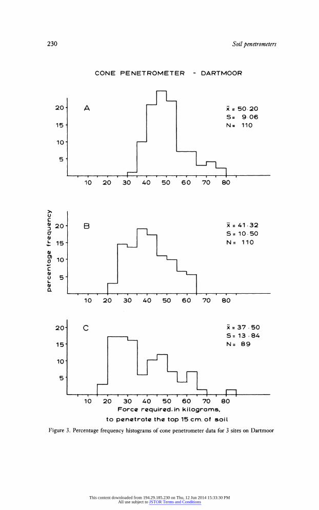
The great variability in penetration resistance over short distances is illustrated in Figure 3, which shows percentage frequency histograms for three sites on Dartmoor. The histograms also show the variations in the shape of the distributions that can be expected. The readings were all taken within a one metre diameter circle at each site, keeping disturbance to a minimum. One of the problems in assessing the results is
m Proving ring
Diat gauge
X'- Cone probe
Figure 1. Main features of a cone penetrometer
This content downloaded from 194.29.185.230 on Thu, 12 Jun 2014 15:33:30 PMAll use subject to JSTOR Terms and Conditions

Soil penetrometers 229
A,,.
Fiue2 Potrpnermtrwihvrey_fpoe
This content downloaded from 194.29.185.230 on Thu, 12 Jun 2014 15:33:30 PMAll use subject to JSTOR Terms and Conditions
230 Soil penetrometers
CONE PENETROMETER - DARTMOOR
20 A x 50.20 S= 9.06
15 N= 110
10
51
10 20 30 40 50 60 70 80
U
,20 B x-41.32 v IS= 10.50
L 15- N= 110
o10.
US
10 20 30 40 50 60 70 80
20- C 37.50 S= 13 .84
15 N= 89
101
51
10 20 30 40 50 60 70 80
Force required. in kilograms,
to penetrate the top 15 cm. of soil
Figure 3. Percentage frequency histograms of cone penetrometer data for 3 sites on Dartmoor
This content downloaded from 194.29.185.230 on Thu, 12 Jun 2014 15:33:30 PMAll use subject to JSTOR Terms and Conditions

Soil penetrometers 231
how to treat those instances where abnormally high values are obtained because the penetrometer probe hits or grazes a stone or large root. In the results here, these values have been omitted. The distributions do not appear to be truncated at their upper ends and this suggests that the resistance of these obstacles is of a much larger order of
magnitude than the range of resistance of the soil and constitutes a separate popu lation of resistance that does not overlap the soil population. The percentage of such
failures ' can, in itself, be a useful soil index. The coefficient of variation is used in this study to demonstrate the level of variability
present in penetrometer measurements and to enable comparisons to be made between the cone and Proctor penetrometers. The values were obtained from 75 readings per site using the cone penetrometer and 25 readings per site using the Proctor pen etrometer. The histograms of ' at a site ' variability, shown in Figure 4, emphasise the great variability in penetrometer readings. There is, however, some suggestion that the Proctor penetrometer produces less variable readings than the cone penetrometer.
This may be because it is easier to force the small blunt-ended probe of the Proctor penetrometer through the root layer and therefore easier to maintain a constant applied pressure.
PROCTOR PENETROMETER
>,. 40 1 X 14.8 U c 50 0 S = 549
N = 36 01 40
CONE PENETROMETER
Figure 4.. Acmasno'a-st'vraitinesretfocnadPorpn295 0 ~~~~~~~~~~~~S= 10.4
10
0 10 20 30 40 50 60 0/0
Coefficient of variation
Figure 4. A comparison of' at-a-site ' variability in measurements for cone and Proctor pen etrometers
The variability will also be influenced by the intrinsic features of the site. The varia bility of Proctor penetrometer resistance appears to be less for Dartmoor than for the Clent Hills (Figure 5) but, in the absence of precisely controlled experiments, this can only be a suggestion. Within a relatively homogenous area there is little difference in the ' at-a-site ' variability. Table 1 shows the mean values of the coefficients of vari ation for 18 sites on each of the upper, middle and lower portions of slopes in the
Clent Hills. None of the mean values are significantly different at the 95% confidence level when tested with the Mann Whitney U statistic.
The great variability shown here is not restricted to hand-operated penetrometers but is also a major problem in the standard penetration tests used at greater depths by civil engineers.22 This extreme variability means that a large number of readings is required to provide a reasonably accurate mean value per site. The results for
Dartmoor suggest that 75 readings per site are needed to obtain an accuracy of ? 10% of the mean at the 95% confidence level. This is considerably more than has been used in the majority of the published studies and the necessity for samples of this
This content downloaded from 194.29.185.230 on Thu, 12 Jun 2014 15:33:30 PMAll use subject to JSTOR Terms and Conditions

232 Soil penetrometers
CLENT HILLS,WORCS
X=27-1 U c l - S=13 3
J ~~~~~~~~~~~~~N=57
~~~ 40 ~~~~~DARTMOOR
30- n X =14.8
C 20- S=5.9
0
U . N=36
eo 10 CL
0
0 10 20 30 40 50 60 0/0
Coefficient of variation
Figure 5. A comparison of 'at-a-site ' variability in Proctor penetrometer measurements for Dartmoor and the Clent Hills, Worcestershire
Table 1. Variability of ' at-a-site ' Proctor penetrometer measurements differentiated according to slope position
Penetration readings Slope position Mean value of Coefficient of Variation
Upper 31.8% Middle 27.9% Lower 2666%
size would appear to be a major disadvantage. Nevertheless, penetrometers are quick and easy to use, even when obtaining 75 readings at each site, and allow sites to be differentiated according to resistance to penetration. The development of a new hand held recording penetrometer,23 which allows data for up to 20 penetrations per plot to be stored and processed within the instrument in the field, facilitates field operation considerably. It can be used both horizontally, into the sides of exposures or pits, or at different depths.24 Figure 6 shows the spread of mean values for 41 sites on
Dartmoor, many of which are significantly different at the 95% confidence level. These differences suggest that penetrometer readings may be used to differentiate sites on the basis of surface resistance. This would be a particularly useful adjunct to many land and soil capability studies. A smaller version, the pocket penetrometer, has been successfully used in estimating the undrained shear strength of weathered soils in a preliminary planning phase of highway construction in Fiji.25
With careful use and an adequate sample size, successful correlations can be obtained with other soil properties. On Dartmoor, cone penetrometer readings were positively correlated with slope angle, percentage sand and percentage gravel and negatively correlated with loss-on-ignition and percentage silt-clay.
Conclusions
Although hand-operated penetrometers possess disadvantages they can provide some
This content downloaded from 194.29.185.230 on Thu, 12 Jun 2014 15:33:30 PMAll use subject to JSTOR Terms and Conditions

Soil penetrometers 233
CONE PENETROMETER
U c c) 20- = 38.54 0' S= 19. 07 L 15- N = 41
o 10 c
L
10 20 30 40 50 60 70 80 90
Force required, in kilograms, to penetrate the top 15 cm of soit
Figure 6. Percentage frequency histogram of mean cone penetrometer measurements for 41 sites on Dartmoor
indication of soil strength and surface resistance. They can also be helpful, in prelimi nary reconnaisance, to identify sites for more detailed soil investigations and for more sophisticated soil measurements. This can provide information which would sup plement the more traditional methods of evaluating soil capability. But the results presented here show that it is important to obtain some information on the variability of penetrometer readings to ensure that an adequate sample size is obtained. Poor sampling designs and inadequate sample sizes can lead to erroneous results and correlations.
Notes 1. Terry, C. W. and Wilson, H. M. (1952) 'The Cornell soil penetrometer', Agric. Eng. 33, 425
2. Culpin, C. (1936) 'Studies on the relation between cultivation implements, soil structure and the crop.
I. Some preliminary observations on the measurement of soil structure with a description of an instru
ment for the measurement of soil resistance ', J. agric. Sci, 24, 22-35. Swanson, C. L. W. and Jacobson,
H. G. M. (1956) 'Effect of soil hardness and compaction on corn growth', Proc. Soil Sci. Soc. Am.
20, 161-7 and Soane, B. D. (1973) 'Techniques for measuring changes in the packing state and cone
resistance of soil after the passage of wheels and tracks ', 7. Soil Sci. 24, 311-23
3. Frietag, D. R. (1968) 'Penetration tests for soil measurements', Trans. Am. Soc. Agric. Eng. 11, 750-3
and Carter, L. M. (1969) 'Integrating penetrometer provides average soil strength', Agric. Eng. 50, 618-19
4. Cockcroft, B., Barley, K. P. and Greason, E. L. (1969) 'The penetration of clays by fine probes and
root tips', Aust. 5. Soil Res. 7, 333-48 and Gerrard, C. J., Mehta, H. C. and Hinojosa, E. (1972) ' Root growth in a clay soil ', Soil Sci. 114, 37-49
5. McKibben, E. G. and Hull, D. 0. (1940) 'Transport wheels for agricultural machines VIII. Soil penetration tests as a means of predicting rolling resistance', Agric. Eng. 21, 231-4 and Strahler, A. H. and Koons, D. (1960) ' Objective and quantitative field methods of terrain analysis ', US Office of
Naval Research, Final Rept. Proj. NR587-021, Contract 266-50
6. Road Research Laboratory (1957) Soil mechanics for road engineers 7. Houston, W. N. and Namia, L. I. (1971) 'Penetration resistance of lunar soils ',. Terramech. 8, 59-69
8. Chorley, R. J. (1974) ' Geomorphological evaluation of factors controlling shearing resistance of surface
soils in sandstone"', . Geophys. Res. 69, 1507-16 9. Slaymaker, H. 0. (1972) ' Patterns of present sub-aerial erosion and landforms in mid-Wales', Trans.
Inst. Br. Geogr. 55, 47-68
This content downloaded from 194.29.185.230 on Thu, 12 Jun 2014 15:33:30 PMAll use subject to JSTOR Terms and Conditions

234 Soil penetrometers
10. Heathershaw, A. D., Carr, A. P., Blackley, M. W. L. and Wooldridge, C. F. (1981) 'Tidal variations
in the compaction of beach sediments', Mar. Geol. 41, 223-38
11. Park, C. (1978) 'Channel bank material and cone penetrometer studies: an empirical evaluation ', Area
10, 227-30 12. One of the exceptions to this is the study by Anderson, G., et al. (1980) 'A new hand-held recording
penetrometer for soil studies ', J7. Soil Sci. 31, 279-96
13. Proctor, R. R. (1933) ' Description of field and laboratory methods ', Eng. News Rec. 111, 286-9
14. Davidson, D. T. 'Penetration measurements', in Black, C. A. (ed.) (1965) Methods in soil analysis,
Am. Soc. Agronomy, 472-84 15. Dexter, A. R. and Tanner, D. W. (1972) 'Soil deformation induced by a moving cutting blade, an
expanding tube and a penetrating sphere', 3. Agric. Eng. Res. 17, 371-5 and (1973) 'The response
of unsaturated soils to isotopic stress', ". Soil Sci 24, 491-502
16. Farnell, D. A. and Greasen, E. L. (1966) 'Resistance to penetration of fine probes in compressible
soil', Aust. 3. Soil Res. 4, 1-17 and Greason, E. L., Farrell, D. A. and Cockcroft, B. (1968) 'Soil
resistance to metal probes and plant roots ', Trans. 9th Int. Cong. Soil Sci., Adelaide, 769-79
17. Reaves, C. A. and Nichols, M. L. (1955) ' Surface soil reaction to pressure ', Agric. Eng. 36, 813-16
18. Reed, J. F. and Rigney, J. A. (1946) ' Some factors affecting the accuracy of soil sampling', Proc. Soil
Sci. Soc. Am. 10, 257-9 and Hammond, L. C., Pritchett, W. L. and Chew, V. (1958) 'Soil sampling in relation to soil heterogeneity', Proc. Soil Sci. Soc. Am. 22, 548-52
19. Carson, M. A. (1967) 'The magnitude of variability in samples of certain geomorphic characteristics
drawn from valley-side slopes', J. Geol. 75, 93-100
20. Gerrard, A. J. (1973) 'Soil particle densities', Area 5, 236-7
21. Freitag, D. R., op. cit.
22. Hooper, J. A. and Butler, F. G. (1966) ' Some numerical results concerning the shear strength of
London Clay', Geotechnique 16, 282-304 23. Anderson, G. et al., op. cit.
24. Hartge, K. H., Ellies, A., Nissen, J. and Macdonald, R. H. (1978) ' Anisotropy of penetration resistance
in four soil profiles in Chile', Geoderma 20, 53-61
25. Lovegrove, G. W. and Fookes, P. G. (1972) 'The planning and implementation of a site investigation
for a highway in tropical conditions in Fiji', Q. 7. Eng. Geol. 5, 43-$8
Dudley Stamp Memorial Fund
Since its foundation in 1968 the fund has made over 50 awards to young geographers (usually under 30 years of age) from a wide range of universities and polytechnics for research or study travel likely to lead to the advancement of geography, or to international cooperation in the study of the subject. The trustees have in mind the desirability of strengthening the contacts between young geographers in Britain and those in other lands. Grants are given to individuals and are not given to assist expeditions. The trustees now have over ?1,000 a year available to support good projects. Application forms are available from The Executive Secretary, The Royal Society, 6 Carlton House Terrace, London SW1Y SAG, and should be submitted by 31 January in each year. Decisions are normally announced in April.
The capital sum and the annual income have shown steady growth and the amount of money awarded in research grants has increased year by year. ?850 has been awarded in 1982 and more is available for 1983. Nevertheless the costs of travel and maintenance have been increasing rapidly and, in current circumstances, there is no need to stress the difficulty which research students and young academic geographers are experiencing in obtaining grants to enable them to travel and to conduct research overseas. The funds available to the trustees have been raised entirely by voluntary subscriptions. The amount spent on administration is virtually nil. Now is a time to help young colleagues who are experiencing the greatest difficulties in obtaining funds for research and the trustees will warmly welcome further donations, which should be sent to Michael Wise, the Joint Honorary Secretary, at the London School of Economics.
M. J. Wise
LSE
This content downloaded from 194.29.185.230 on Thu, 12 Jun 2014 15:33:30 PMAll use subject to JSTOR Terms and Conditions