The Use of Concrete in Underground Mine...
67
The use of concrete in underground mine structures Item Type text; Thesis-Reproduction (electronic) Authors Petersen, N. P. (Nels Paul), 1898- Publisher The University of Arizona. Rights Copyright © is held by the author. Digital access to this material is made possible by the University Libraries, University of Arizona. Further transmission, reproduction or presentation (such as public display or performance) of protected items is prohibited except with permission of the author. Download date 19/05/2018 15:55:26 Link to Item http://hdl.handle.net/10150/553140
Transcript of The Use of Concrete in Underground Mine...

The use of concrete in underground mine structures
Item Type text; Thesis-Reproduction (electronic)
Authors Petersen, N. P. (Nels Paul), 1898-
Publisher The University of Arizona.
Rights Copyright © is held by the author. Digital access to this materialis made possible by the University Libraries, University of Arizona.Further transmission, reproduction or presentation (such aspublic display or performance) of protected items is prohibitedexcept with permission of the author.
Download date 19/05/2018 15:55:26
Link to Item http://hdl.handle.net/10150/553140

The Use of Concrete in Underground Mine Structures
byNils Paul Peterson
Submitted in partial fulfillment of the requirements for the degree of
Master of Science
in the College of Mines and Engineering
University of Arizona
1932
70
: n "
CONTENTS
?79/ / 932.3 x.
3l.
Page.Introduction . . . ........ . . . . . . . . . . . . . 1Classification of methods . . ....................... 5Hand placing ................... .................. • • 6Gravity p l a c i n g ..................................... 8
Shaft lining . . . . . . . ...................... 8Drop-shaft lining with caissons . . . . . . . 9Ounite method . . . . . .................. . 9Pre-cast members.................. 10Ring method ............................. .. . 11Continuous monolithic lining ................ 12
Shaft-station lining and support ............ 29Ore-loading p o c k e t s .......... 33
Pneumatic p l a c i n g ..................................... 39General discussion................................ 39Placing machines.................. 40Tunnel lining .................................... 48Station lining......................... 53
Wall construction.......................... 54Roof construction............................. 56
Bibliography........................... 60
85770

ILLUSTRATIONS' ' ■ Page.
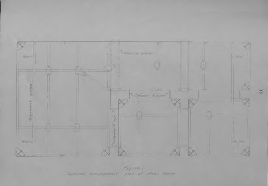
Figure 1, Qenepal arrangement plan of steel form . . . 1 62. A typical section of the Riverside shaft,
showing the equipment and the locationof bolt-inserts . . . . . . , . . . . . . 1 7
3. A pre-cast concrete shaft divider .. . . . 194. Corner detail of steel shaft-forms ... . . . 195. Steel form leveling device . . . . . . . . . 226. Showing the method of casting bolt-sockets
in the shaft wall . , . . . ; . . . . . ; 227. Receiving hopper used in eoncreting the
Riverside shaft ....... , . . . . . . . . . 228. Showing a typical shaft-station and the
method of building and supporting the forms . . . . . . . . ... . . . . . . . . 30
9. Section through the Riverside pocket at rightangles to the long axis of the shaft . . . 54
10. Section through the Riverside pocket parallelto the long axis of,the shaft . . . ... . . 35
11. Ransome pneumatic concrete placer . . . . . ... 4212. Showing the use of panel form in tunnel
* lining . . . . '. . . . . . 8113. Showing tunnel lining in swelling ground . . 5114. Plan showing the arrangement of delivery pipe,
receiving, and troughs for pouring station walls . . . . . . . . . . . . . . . . . . 55
15. Elevation showing same as figure 14. . . . . 5 516. Elevation showing the arrangement of delivery
for pouring station roof . . . . . . .. . . 55
17. Receiving hopper used with pneumatic placerin pouring station wall . . . . . , , , , 67

1
*, '
INTRODUCTIONReinforced concrete has been used In
the support and lining of underground openings for nearly thirty years but It is only in the last half of this period that it has come Into general use as a major material in underground construction. At first the use of concrete in mines was confined entirely to shaft lining and it was not until after the development of the pneumatic placing machines that concrete could be placed successfully in all types of mine structures. The technique has been quite well developed by a limited number of individuals working independently in various districts, but practically nothing has beeii written to give other operators the benefits of the experience gained.
Although in mine work no two jobs will present exactly the same problems because of the difference in local conditions such as the nature of the ground to be supported, the application of the structure to a plan of operation already in force, and the lack of standardization In mine plant design, there are certain principles and methods that are quite general in their application.
In underground concrete construction the engineer has conditions to contend with that are entirely different from those of surface construction. It is seldom possible to mix the concrete at of even near the

2
place where It is to be used except in the case of small jobs where the mixing can be done by hand. More often the mixing must be done on the surface, the concrete carried or chuted down a shaft, and then must be transported in ears or by means of compressed air to the forms which may be up to 2800 ft. from the shaft. On the surface it is always possible to distribute concrete economically over a large area by the use of elevator towers and long, inclined gravity chutes; but in a mine transportation must necessarily follow existing openings which are usually horizontal. :
The limited space underground may offer unusual difficulties to form building and in the placing of reinforcing steel. The work must be carefully planned and scheduled, checked for error continuously for once a form has been built its interior becomes inaccessabls^ Puddling the concrete In the forms is rarely possible and other methods must be devised to insure against segregation.
The rock side or back of an underground opening usually serves as one.side of the form. For this reason no tie-wires can be used to sustain the form and all bracing must be done from one side by means of struts and angle-braces.
r Concrete poured in mines takes its initial set much more slowly than under surface conditions and may remain liquid throughout even a relatively, long pour; consequently the pressure on the form becomes enormous and
5
is augment®# by the slight agitation cause# by the pouring of each new batch into the: form. The amount of bracing necessary to prevent bulging and shifting of the fora appears so unreasonable to the man accustomed to surface work that he usually comes to grief on his first'attempt underground. Very often the ground against which the concrete is to be poured is loose or swelling and must be supported while the forms are being built and"the concrete poured. Swelling ground offers serious difficulties and unless the proper precautions.are taken the concrete fails before it has had time to develop its full strength. . ; —
The designer is also beset .with difficulties in this type of work (for unless he has actually had some experience as a workman or engineer in underground : concreting he is unable to vlsuallize the conditions under which the work must be done. While designing the reinforcing he must be able to form a mental picture of the restricted space in which a given bar is to be handled and of howit will be inserted into the form. To overlook this detail
■ . ■may cause serious delays for the construction crew. Also,the designer has no clear-out data from which to calculate loads for although several theoretical formulas have been derived for determining rook pressures, it is hardly once, in a lifetime that conditions are suited for their application. Nearly every experienced designer has some method of hia own for determining the rock loads, but the writer

4
believes that in the great majority of oases rook pressure can he ignored entirely, that is, if the walls and roof ofan underground structure are designed to support their own
' • • •-> < • • . • » - -"
weight, allowing the usual factor of safety , there is little danger of failure by rock pressure. Caving is ordinarily due to air-slaking or crumbling of the rock walls, and once the concrete lining is in place, air is excluded, and if proper- ly applied the ccmerete forces its way into the cracks of
. ‘ " ; V' * ' ' • “ I ’ ■ 1 » > * » . " ■ * * r" ‘ ' • ; • • 4-- 1 < «--v *' •• t ■ * - - * ‘ f ' ‘ - , ' - . ‘ , # • *
the rook, thus binding and keying the fragments so that no movement can begin. This of course does not apply when working in swelling ground. It is possible to get a good idea of the pressure exerted by swelling ground by studying the effects on timber supports in existing openings. Large scale experiments, such as submitting a trial section of tunnel lining to the rock pressure, may even be necessary in order to determine a basis for calculating loads.
A designer, experienced in underground construction, is an important factor to the efficient functioning of a mine concrete-crew, but unfortunately the field is as yet too limited to permit much speclallisatlon. The use of concrete in mine construction is, however, increasing rapidly, for although the first cost is greater than for timber construction, once in place, concrete is permanent, and further expenditures for replacements or repairs are seldom necessary.
5
CLASSIPICATIO* OF METHODSUnderground concrete work may be divided
Into three general claasea according to the method used In filling the forma; they are (1) hand filling (2) gravity filling, and (3) pneumatic placing. The first method Is used mainly oh small jobs where only a few yards of concrete la required; the mixed concrete Is baled or shoveled Into the fora. Ho special equipment or technique Is necessary.
Gravity filling has!Its most Important application In shaft lining, but may also be used In lining shaft stations and ore loading-pockets. Gravity filling Is applicable to any structure accessible from above so that concrete can be made to flow by gravity into every part of the fora from a high point.
The third method, pneumatic placing, is used extensively in tunnel lining and in all cases in which the concrete must be mixed at a lower elevation than that of the top of the form, or when it must be transported long distances horizontally.
All three of these methods were used in the mine of the Riverside Cement Co. under a wide variety of conditions so that nearly every phase of their application is illustrated In some part of the work. This mine Is unique in that, Instead of starting as a small prospect and gradually growing into a large producing mine, the whole
6project was planned for a definite dally capacity before any actual development work was started. W® were able, therefore, to consider carefully the details of design of each structure and piece of equipment not only as a unit, but also as a part that must fit nicely into the project as a whole. Consequently this mine is. In every sense of the phrase, a model mine. Concrete was used in place of timber In all permanent construction. We were able to profit by the>experience of the operators of several of .the large copper producing companies of the Southwest and were thus assisted in making a number of improvements in the technique of - construction and con- crete placing. The details of some of the work at Riverside will serve as a basis for this discussion.
HAND PLACIMO .Hand placing was used at Riverside only
in small isolated jobs such; as bulkheads, chute bottoms, small foundations for machines, and short lengths of .tunnel lining. The operations were so simple that no discussion of them appears necessary.
A mechanized variation of the hand placing method was used in concreting a large underground hoist-room lately completed at the United Verde Mine at Jerome, Arizona.1 The completed excavation for this room
1 Mills, C.E., 1930.
Eng. and Min. Jour., vol. 130, pp. 599,

7was 122 by 44 ft. with an arched back having a radius of 22 ft. The rook walls were strong but rather blocky, and required some support to prevent loose slabs from spalling off, also some means of support was required for the crane girders to handle the mechanical equipment. The ring or rib method of concreting was therefore chosen, the rings being 3 ft. 6 in. wide and spaced 8 ft. center to center. Section- allzed forms were used consisting of five circular segments; the sides of the form were sheathed to the wall with 1 by 6-in. boards. The mixer was placed under the ring to be filled and discharged into a small bucket. The bucket was elevated by means of an air-hoist and the concrete poured by gravity into the forms through movable troughs. The upper portion of the form which could not be filled by gravity was concreted by means of a small pneumatic placer. The sixteen rings and end ribs required a total of 316 cu. yds. of concrete. The spaces of bare rock between the rings were later given two coats of gunite to prevent air-slaking and spalling.
" : :■ r. ‘ •. ' U ::

8
GRAVITY PLACING SHAFT LINING
In 1905 a shaft was lined with concrete in a coal mine at Tug River, VJest Virginia;2 This was the first shaft to be concrete lined in the United States and probably in the world. It is significant that continuous monolithic concrete was used, which is the design most prevalent In modern practice. This shaft was elliptical in cross-section. Sectional wood forma were used; Tho mixed concrete was lowered from the surface in buckets, dumped on a platform, and shoveled into the form. Ho reinforcing was used. ' ' ' • '' - ' ' " ' - - ’
The use of a pipe line for transporting the mixed concrete down the shaft was introduced at Globe, Arizona in the Kingdon Shaft in 1912.3 Here the concrete was dropped over 1000 ft. through a 4-in. steel pipe. This was an important advance in the art and greatly increased the rate of pouring.
Five typos of concrete shaft-lining have been developed: (1) drop-shaft lining with caissons (2) the gunlte method (3) pre-east members (4) the ring method, and
2 Concrete Shaft Lining, Eng. and Cont., vol. 45, pp. 144 1916
3 Concrete Lining of the Kingdon Shaft, Eng. and Min. Jour, vol. 95, pp. 177, 1913.

9
(5) continuous monolithic lining.
DROP-SHAFT LINING WITH CAISSOHSDrop-shaft or open caissons are used
only in soft water-hearing soils. The method requires a very speciallized technique and highly trained operators. The cost is prohibitive and the results are not always satisfactory because of the difficulty of maintaining the alllgn- ment. In late years grouting processes for the cementation of unconsolidated sediments and the Francois cementation process for the sealing of water-bearing strata have been so highly developed that it is doubtful whether any case will arise in the future to necessitate the use of caissons in mine work.
, OUNITE METHODOuniting is the application of cement
mixtures by means of a special machine. By the use of this appliance a uniform stream of sand thoroughly mixed with a definite proportion of cement In suspension in air under pressure, is passed through a rubber hose and discharged through a nozzle in which a uniform stream of water is admitted, upon the surface that it is desired to coat. Such a coating applied to a dry surface and thoroughly set has a high degree of imperviousness, being 0.7 to 0.05 times as pervious to water as a similar hand-made surface. Hand-made

10
mortars absorb 1.4 to 5.3 times as much water as gunite, and has much weaker adhesion properties. Gunite lining may be used over shaft timbers as a protection against fire. It has little or no value as support except to prevent the disintegration and crumbling of rocks that slake when exposed to air. Gunite has a serious disadvantage when used to cover timber, in that dry-rot soon begins, of which there is no external evidence until failure takes place.
PRE-CAST MEMBERS .Pre-cast shaft sets have been used to
some extent in the Michigan iron mines. A case has also been reported lately from the Portovelo-Abundancla mines in Ecuador in which timber sets were replaced by pre-cast members.4 These members consisted of wall plates, end plates, and dividers, notched so that they could be be laid up as cribbing. Concrete was used because the native timber would not stand up, and foreign timber was too expensive. This type of construction was adopted because hoisting could not be suspended for more, than 8 hours a day, which was considered too short a period to permit installing a monolithic lining.It appears doubtful.that there was any grounds for this■ ' "... , . . , • • 1 : / . :...■ - *assumption. " 4
4 Banghart, M.D., Shaft Concreting at Zaruma, Ecuador, Eng. and Min. Jour., vol. 130, p. 277, 1930.

11
There la little or nothing to reccommend the use of this method, however, pre-east dividers are used In connection with cmtinous monolithic linings In nearly all modern shafts. Their use will be discussed in detail later In this paper. ' . ^
: " ' - -:' : RING METHOD :v; 1 •• . : ' ■ " :The ring method has proved satisfactory
In shafts where the ground is firm enough to permit its use, the chief advantage being the saving in concrete. Adequate support Is provided for bldcky but otherwise firm ground.The concrete rings are as satisfactory for supporting guides, pipes, and other shaft equipment as continuous lining.
The man and material shaft of the United Verde Copper Co. at Jerome, Arisona was lined in this wayj using concrete rings 30 in. high, placed at 6-ft. intervals, ^he saving accomplished by this method as compared to continuous^ lining used elsewhere in the same shaft is reported to be $87 per ft.^ concrete rings have also been used sucess- fully in several shafts on the Rand in South Africa.
° De Camp, W.V., Ring Min. Jour., vol. 121, p,
Method of Shaft 329, 1926.
Concreting, Eng.and

12
CONTINUOUS MONOLITHIC LIBIHGthis is the method most generally used
at the present time in American mining practice. Reinforced monolithic lining has proved more satisfactory than all other types of lining, viewed from the standpoint of hoth construction and operation. This type of lining practically obviates the necessity of future shaft repairs and upkeep expense; it provides perfect and permanent support for troublesome ground as well as for the Installation of guides, pipes, ladders, and other equipment. Water-bearing strata can be completely sealed off by grouting behind the concrete lining. There is no reason why a shaft so lined cannot be maintained in practically dry conditions.
Where possible, concreting.is begun at bottom of the finished shaft, and is carried upward to the collar in a single, continuous operation; but in heavy or swelling ground this is nfct possible, and the work must be carried on In cycles, sinking as far as is considered safe then concreting. The Chiof Consolidated Shaft in Utah was driven in swelling ground.6 Sections,76 to 100 ft., were alternately driven and concreted. Shaft sets, framed from 6 by 6-ln. timbers, were placed at 2&-ft. intervals and
6 Gardner, R.D., Chief Consolidated Shaft at Eureka, Utah, Eng. and Min. Jour., vol. 110, p.460, 1920.
13
lagged tight so as to serve as the Inside concrete-form.- The excavation was made much larger than the finished shaft, and an outside form Was built. Concrete butt-blocks, 12 in. square, were placed at close intervals from the shaft wall to the rock. This type of construction allowed the concrete to thoroughly set before it received the full thrust of %he swelling ground. Continuous operation, where the concreting crew works over the sinking crew, has been tried, but has not proved satisfactory nor economical because of the interference of the two crews and the element of danger Involved. In other shafts, concreted through swelling ground, no butt- blocks are used between the concrete wall and the rock.The space between the outside form and the rock is tightly packed with straw, which acts to prevent sloughing of the loose ground and later as a cushion when the rock closes In on the concrete walls.
A modem example of the use of wood forms is that of the Pyne and Bongo Shafts of the Woodward Iron Co.^ Here, permanent steel shaft-sets were erected on 6-ft, centers, using 6-in. H beams for wall plates, end plates, and dividers; 3 by 4-in. angles were used as posts. The H beams were placed with the flanges vertical. The lagging was Inserted from web to web, and wedged tightly 7
7 Stovel, J.H., iyne and Songo Shafts, Eng. and Min.Jour., vol. Ill, p. 698, 1921.

14
against the outer flange. When the concrete had oefc the lagging was removed. Guides and other equipment were bolted to the steel members.
Steel forms of various designs are used almost exclusively now in shaft concreting. The design used depends largly on the conditions under which the work must be carried on. If the shaft Is In use, and the concreting being done between shifts, the forms must be designed without internal bracing in order to give free passage for the skips or cages. Such forms must necessarily be of heavy construction, and should be avoided whenever Internal bracing Is possible.
The Sacramento Shaft at Bisbee, Arlsona was concrete lined in such circumstances.8 The shaft was in service 14 hours a day, the remaining 10 hours were reserved for concreting. Heavy steel forms were used requiring no internal bracing. A solid 10-ln. wall was cast between the two skip compartments, 10 by 10-ln. pre-east concrete dividers were used between the other compartments. The forms were 5 ft. 9in. high, overlapped the finished concrete 9 in. A series of bolts, east In the concrete at 5-ft, intervals, was used to support the form. Some difficulty was experienced at first In getting the forms in place at the overlap,
8 Sacramento Shaft at Bisbee, Min. and Sol. Press,Oct. 7, 1916.

15
but this was later remedied by riveting a 9-in. strip of thin steel around the top edge of the form, which served to slightly enlarge the compartments at this point. The form
■> for each compartment was in two units, hinged at the corners; the two units were joined at the guides. The guides were plumbed before the work was started, and were used to maintain the alignment. Three sets of forma were used, and concreting was carried on at three horizons in rotation.
Collapsible steel forms were used in lining the Riverside Cement Go. shaft, the general arrangement of which is illustrated by figure 1. The two skip- compartments were entirely enclosed by 8-in. walls; pre-cast concrete dividers were used between the pipe-compartment and manway, also between the manway and the elevator-compartment. Figure 2 is a typical section of the completed shaft showing the position of pipes, manway ladders and platforms, skip- guides, elevator and counter-weight guides. All bolts and bolt-inserts for supporting this equipment were cast into the concrete as the work progressed.
All of the concrete dividers were castand cured before the work in the shaft was begun. Each
/ : 'divider was marked with red paint to shew exactly where andhow it was to be placed. This was necessary because some had bolts for fastening manway platforms, others had bolts for fastening ladders, and those to be placed between the manway and elevator compartments had holes through them for bolting

t - i fu r e 2 / i f t /p ic o / s e c tio n a / f/)e F2iv'erctide < rh a f/ j 'A o w /iq the.e> mpmer? f o/7d the /ecotfon at ho// inserts

18
the screened panels that would toe used to separate the two compartments. ( see fig. 3 )
Each section of the steel form was 3ft. Gin. high, and consisted of 22 panels, each of which was small enough that it could be passed up between the braces of the sections In place above it. The panels were made of 12-gauge plates, reinforced with light angle Irons spot- welded to them; .2 by 2-in. angles were used along the top and bottom edges. By this construction the panels were made light and easily handled, the largest weighing only 163 pounds, yet strong enough to prevent bulging and to withstand the effects of rough handling. :
To facilitate the removal of the form from the finished concrete the two panels that make up each interior corner were cut one inch short; a removable corner piece was Inserted from the inside to complete the corner. These corner pieces consisted of vertical, 2 by 2-in. angle irons, which were forced Into the corners and held there by a simple jack arrangement, (see fig. 4)
The bottom angle iron on each panel was attached so that the plate projected three-quarters of an Inch below the face of the angle. At Intervals of approximately 18 In., holes were drilled in the horizontal legs of the angles, and a one-half-inch nut was welded over each hole. Short one-half-inch bolts were screwed Into these nuts from the top side. The top angle, on the other hand, was


20
attached so that it projected one inch above the top of the plate. When two eeetiona of form were assembled, one on the top of the ether, the ends of the bolts in the bottom of the top section rested on the top angle of the lower section (see fig. 5). For the normal height of section the projection of the holts was one quarter ineh, thus permitting an adjustment of one quarter inch either up or down. This type of joint greatly facilitated the leveling of the sections; also a small loss or gain in elevation could be corrected by adjusting these bolts.
The form sections were made up in pairs. One section of each pair had recesses in the lower edge so as to rest halfway down over the pre-oast dividers; in the other section of each pair there were corresponding recesses in the top edge to receive the lower half of the divider.Two pairs or four sections in all were used. The dividers were spaced 7& ft. center to center vertically or, in terms of form units, two sections apart.
Standard bolt-inserts made by the Trus- con Steel Co. were east into the concrete at regular Intervals to support the elevator and skip guides. The elevator guides were 15 ft. long and required supports spaced 7i? ft. apart. As this distance was an even multiple of the form-section height it was a simple matter to work out a system of bolt-holes in the forms for spacing the inserts. In the skip compartment the inserts were bolted

21
to 1 by 12-in, boards, ft. long, which in turn were bolted tb the steel forms. The boards with inserts attached were prepared in advance for the entire shaft from a schedule devised by the engineers. For supporting temporary working-platforms, manway platforms, and pipe hangers, bolt sockets were used. These were made by embedding in the concrete half-inch nuts held at the end of a 4-in. length of half-inch pipe, (see fig, 6)
Two sections of form, or 7& ft., were filled at one pour. Three 8-hour shifts were required to complete one operation, which included removing a set of shaft-timbers, stripping and erecting two sections of form, placing the reinforcing steel, pouring the concrete, and cleaning up. Short boiler-maker's bolts were used for assembling the form. As the panels were stripped they were thoroughly cleaned with a wire brush, and given a coat of grease to prevent their sticking to the concrete.
The alignment was maintained by four weighted wires hung from points set by the engineers. When the form was exactly in place these wires passed through the center of notches in templates bolted to the top of the form ( see fig. 1, p. 16).
. The rock was unusually solid, andrequired very little support. Ho attempt was made to design the reinforcing other than to compensate for temperature changes, allowing a large factor of safety.

22^ 6 ptpe
f'igure SCTtee/- form /evc/< n y dey/ce.
f^tyure 7 - fi?ece(r(n<y /topper dsed cn concref/ry t/te fPiyero/de <7do ft
f / y u r e 6 ^y/totymcf f / t e m e / / r o d o f c a s /tr< ? do/f - yJocde/'S trt the /raf/ *<a //,

25
In the first shafts to be concrete lined in this'country the mixed concrete was lowered In buckets, dumped on a platform, from which it was shoveled into the form. In tee deeper shafts there was naturally segregation of the-aggregate in the buckets^ and some remixing was necessary at the platform. Later, buckets with ports atthe bottom were introduced. These were used in conjunction with light troughs which could be quickly hung under the ports to convey the concrete into the forms. In tee Palms Shaft in Michigan a specially designed, hopper-bottomed skip and portable spout# were used for concreting certain isolated portions of the shaft. the use of a pipe line for ehuting the mixed concrete down the shaft was introduced in 1912, and since that time this method has almost entirely displaced the use of buckets and skips; however, in the Pyne Shaft, concreted in 1920, buckets were used because the aggregate was considered too course to be passed through a pipe. In most cases 4-inch pipe is used, and is probably more satisfactory than larger pipe when the drop is over 500 ft. because the friction in the smaller pipe acts to retard excessive increase in velocity. On the other hand, the wear is greater on the smaller pipes, and usually makes numerous replacements necessary. In the Sacramento Shaft 8
8 Sacramento Shaft at Biebee, Min. and Sel. Press,Oct. 7, 1916.

24
at Blsbee a 4«ln. line was used for a maximum depth of 1640 ft. The pipe line was made up of 10-ft. sections, which were accurately sized to length and flange-connected throughout in order to facilitate replacements. As the sections were removed from the lower end they were used to replace worn sections in the remainder of the line. In addition to the original equipment 67 ten-foot lengths were required. A total of 6270 cu. yds. of concrete was used in concreting the 1640 ft, of shaft. If 820 ft. is taken as the average length of the line, and 2310 ft. as the total amount of pipe used, each section of pipe was replaced 2.8 times, or in terms of concrete transported, each pipe may be considered to have had a capacity of 2240 cu; yds. of concrete before wearing through. The maximum amount of wear occurs at the joints. This can be greatly reduced by screwing the pipe entirely through the flange, and then machining the end so as to be flush with the face of the flange.’ The danger of blocking the pipe is muchgreater in a pipe of small diameter, and mere care is required in feeding the concrete into it. Just before pouring is begun the pipe should be lubricated by a sloppy batch of neat cement and water. If the concrete la fed too slowly it runs down the sides of the pipe, this causes the water to separate from the aggregate, which is then apt to cling tb
the walls of the pipe and cause blocking. When fed too fast it builds up in the hopper, and clogs at the mouth of tho
28
pipe, or forma a plug that slips alowly down and often becoming lodged. The concrete should be fed as fast as the pipe will take It away, that Is, the pipe should be kept as full as possible but without permitting.any excess in the funnel.. . \v
; If a stoppage of the pipe line doesoccur it can usually be broken if the proper measures are taken without delay. When the point at which the line is blocked has been located by tapping on the pipe the obstruction can usually be jarred loose by a few sharp blows with a hammer at a point on the pipe two or three feet below the stoppage. Striking at the point of stoppage or above it tends only to pack the concrete tighter. If this method falls the pipe must be disconnected, and cleared by ramming with a rod. Though occasionally necessary this method should be avoided if possible, aa there la seldom any way of preventing the released concrete from pouring down the shaft.Any attempt to force the obstruction by building up a head of concrete above it is futile, and only makes matters worse.
An experienced mixer-operator can easily tell by the sound Issuing from the top of the pipe whether a stoppage has occurred. When the concrete falls freely it Is accompanied by a downward rush of air into the pipe, whereas if the pipe is clogged the concrete Is hindered from
entering the pipe by the escape of air being displaced.
26
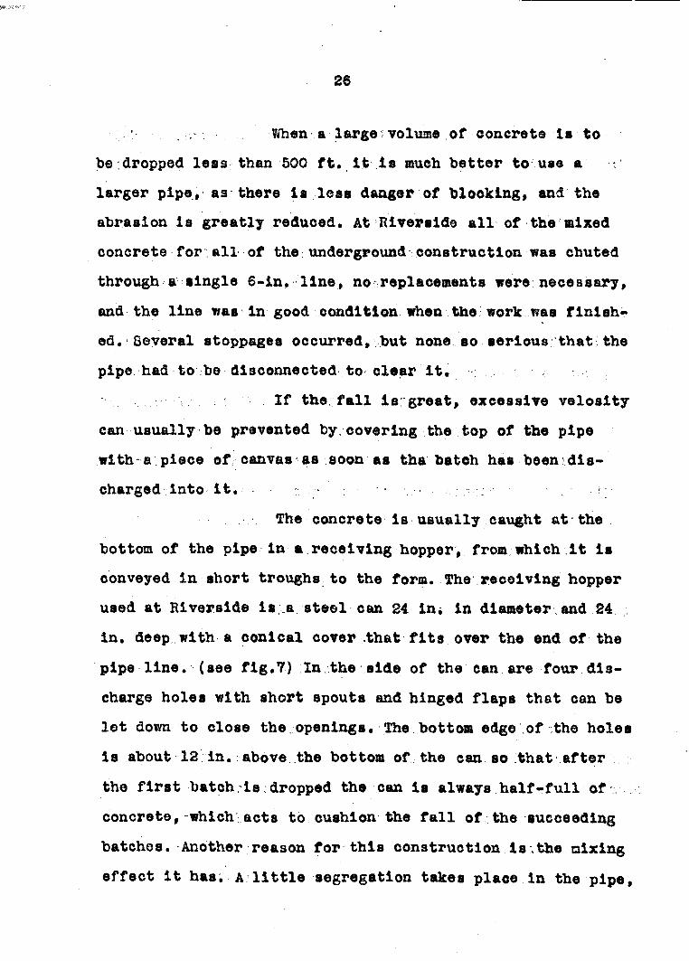
• r V/hen a large ; volume of eonerete Is tobe;dropped leas than 500 ft. It Is much better to use a -larger pipe, as there Is leas danger of blocking, and the abrasion la greatly reduced. At Riverside all of the mixed concrete for all of the underground construction was chuted through a single 6-in. line, no replacements were necessary, and the line was in good condition when the work was finished . Several stoppages occurred, but none so serious that;the pipe had to be disconnected to clear It. ;
If the; fall la great, excessive velosity can usually be prevented by, covering the top of tee pipe with-a piece of canvas as soon as the batch has been discharged Into It, . - ■ v / v ; : : . ' i • •
The concrete is usually caught at the bottom of the pipe In a receiving hopper, fr<m teloh It is conveyed in short troughs to the form. The receiving hopper used at Riverside is .a steel can 24 in* In diameter and 24 In. deep with a conical cover that fits over the end of tea pips line, (see fig.7) In the side of the can are four discharge holes with short spouts and hinged flaps that can be let down to close the openings. The.bottom edge of the holes is about-12:in. above.the bottom of tee can so that after the first batch is;dropped the can is always half-full of concrete, which acts to cushion the fall of the succeeding batches. Another reason for this construction is .the mixing effect it has. A little segregation takes place in the pipe.

27
which is corrected by the agitation produced as the eoaorete falls Into the half-full can, and holla up theaides and out of the apouta. Other types of receiving hoppers have been found satisfactory| the one most commonly seen Is made by cutting a hole in the aide of an ordinary sinking-bucket, and attaching a short spout under the hole. The bucket is usually suspended by a chain from an overhead timber so that by turning the bucket the discharge can be made to flow in any direction. In some case anno .-receiving- hopper ::was used, for example, at the Palms Shaft a 5-in. lateral with a plug in one end and a short length of 6-in. pipe screwed into the opposite end was slipped over the end of the 4-ln. line.This simple device is reported to have worked successfully to absorb the shock of the falling concrete, and to divert the flow into the distribution troughs. The hopper used at Riverside has the advantage, however, in that the pour can be distributed to all four sides of the shaft simultaneously thus permitting perfect control. Even filling on all four sides is the simplest insurance against shifting of the form.
Cost data, giving the actual cost per foot, are of little value to the engineer for estimating the budget for a proposed shaft-lining job. The figures available are not comparable for obvious reasons. Labor and material costs vary from year to year as well as in different localities. Furthermore, no two shafts appear to have been lined
28
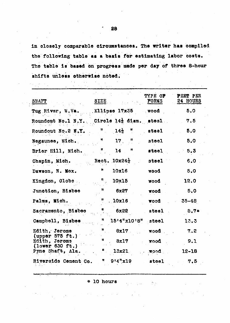
In closely comparable circumstances. The writer has compiled the following table as a basis for estimating labor costs. The table la based on progress made per day of three 8-hour shifts unless otherwise noted.
SHAFT SIZETYPE OF FORMS
FEET PER 24 HOURS
Tug River, W.Va. .Ellipse 17x35 wood 5.0Roundout No.l K.Y. Circle 14& diam. steel 7.5Roundout Mp.2 N.T. . 0 14& w steel 5.0Hegaunee, Mich. M 17 n steel 5.0Brier Hill, Mich. ## 14 " steel 5.5Chapin, Mich. Beet. 10x24^ steel 6.0Dawson, N. Max. ## 10x16 wood 5.0Klngdon, Globe , 10x15 wood 12.0Junction, Blsbee n 6x27 wood 5.0Palms, Mich. w 10x16 wood . 35-48Sacramento, Blsbee # 6x22 steel 8.7*Campbell, Blsbee m 15'4"xl0'8" steel 13.3Edith, Jerome w 8x17 wood . 7.2(upper 575 ft.) Edith, Jerome w . 8x17 wood 9.1(lower 630 ft.) Pyne Shaft, Ala. * 13x21 wood 12-18Riverside Cement Co M 9'4"xl9 steel 7.5
* 10 hours

29
The unusual rate of progress reported in the Palms Shaft and in the Pyne Shaft is due to the fact that lining was accomplished by simply pouring concrete behind steel shaft-sets as was described earlier in this paper.
The else of the concreting crew depends entirely on the else of the shaft. Crews of 6 to 10 men were employed in the shafts listed above, this number does not include holstman, top-men, or other surface workers. Ho special mixer-crew is required, for when the forms are ready to fill part of the underground crew can go to the surface to operate the mixer. Never more than 2 to 5 men are required at the forms when the concrete is being poured.
SHAFT-STATION LINING AND SUPPORTThe shaft-stations on the main working
levels in the Riverside mine were concrete lined using the gravity method for pouring the concrete into the forms. The stations were excavated and concreted before work on the shaft lining was begun, and therefore a construction joint was made corresponding with the position of the outer side of the proposed shaft wall. Dowels of reinforcing steel were left in the joint to insure a satisfactory bond with the shaft concrete.
A typical shaft-station is illustrated by figure 8. The design is very simple, and is especially

II
yvre S. K StotvuK? a fyjCHCa / a/raff ssfaf/cn method of bi/i/dtny and ysvpporft ny f/re formas
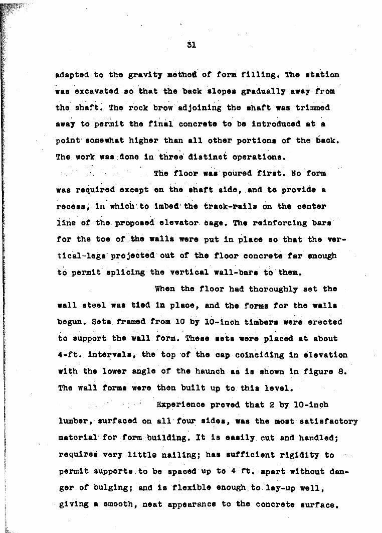
adapted to the gravity method of form filling. The station was excavated so that the back slopes gradually away from the shaft. The rook brow adjoining the shaft was trimmed away to permit the final concrete to be introduced at a point somewhat higher than all other portions of the back.The work was done in three distinct operations.
The floor was poured first. No form was required except on the shaft side, and to provide a recess, in which to imbed the track-rails on the center line of the proposed elevator Cage. The reinforcing bars for the toe of the walls were put in place so that the vertical legs projected out of the floor concrete far enough to permit splicing the vertical wall-bars to them.
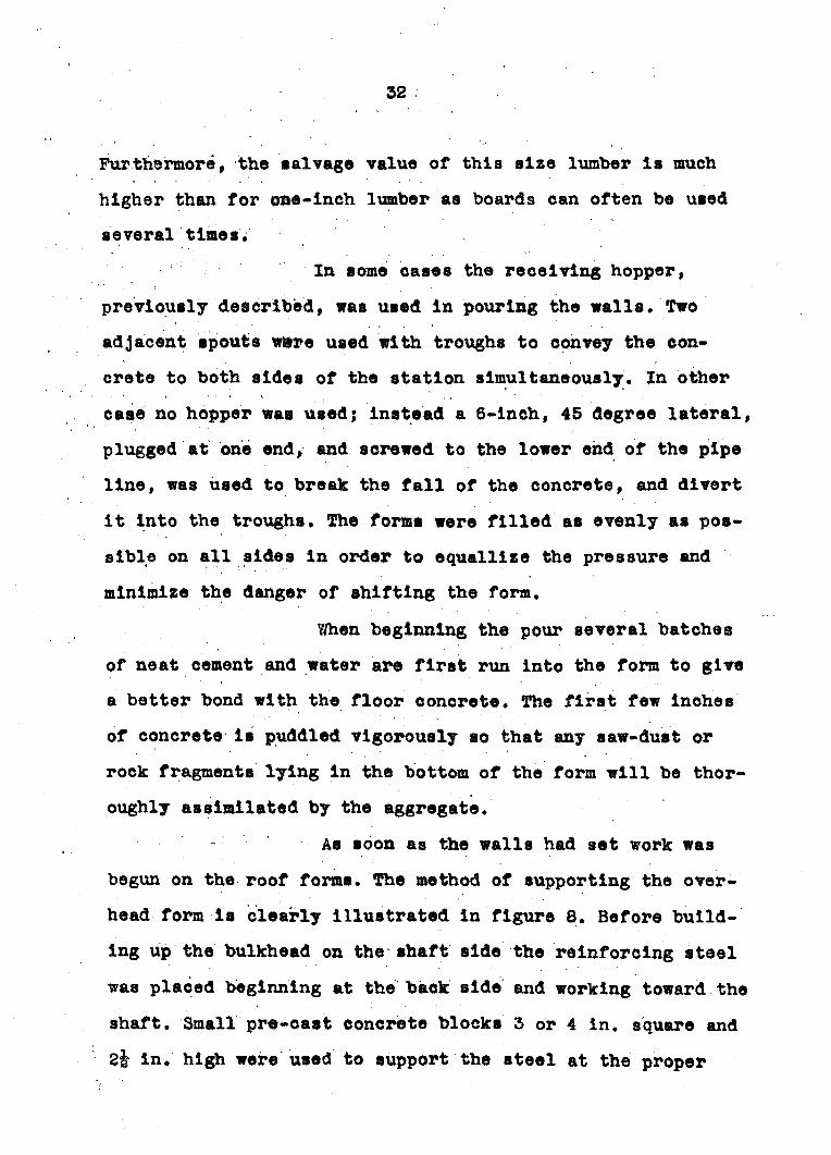
When the floor had thoroughly set the wall steel was tied in place, and the forms for the walls begun. Sets framed from 10 by 10-lneh timbers were erected to support the wall form. These sets were placed at about 4-ft. intervals, the top of the cap coinciding in elevation with the lower angle of the haunch as is shown in figure 8. The wall forms were then built up to this level.
Experience proved that 2 by 10-inch lumber, surfaced on all four sides, was the most satisfactory material for form building. It is easily cut and handled;
requires very little nailing; has sufficient rigidity to permit supports to be spaced up to 4 ft. apart without danger of bulging; and is flexible enough to lay-up well, giving a smooth, neat appearance to the concrete surface.
. 32
Furthermore, the salvage value of this size lumber Is much higher than for one-Inch lumber as boards can often be used several times.
In some cases the receiving hopper, previously described, was used in pouring the walla. Two adjacent spouts were used with troughs to convey the concrete to both sides of the station simultaneously. In other case no hopper was used; instead a 6-inch, 45 degree lateral, plugged at one end, and screwed to the lower end of the pipe line, was used to break the fall of the concrete, and divert it into the troughs. The forms were filled as evenly as possible on all sides in order to equalllze the pressure and minimise the danger of shifting the form.
When beginning the pour several hatches of neat cement and water are first run into the form to give a better bond with the floor concrete. The first few inches of concrete is puddled vigorously so that any saw-dust or rock fragments lying in the bottom of the form will be thoroughly assimilated by the aggregate.
As soon as the walls had set work was begun on the roof forms. The method of supporting the overhead form is clearly illustrated in figure 8. Before building up the bulkhead on the shaft side the reinforcing steel was placed beginning at the back side and working toward the shaft. Small pre-east concrete blocks 3 or 4 In. square and So in. high were used to support the steel at the proper

53
distance above the form.The concrete line entered the form at
the highest point of the rock brow. A 12-ft. length of light blower-pipe was used at the beginning of the pour while the back end of the form was being filled. When no more concrete could be forced to the back end of the form the pipe was removed, and the remainder of the form was filled directly from the main pipe line. The bulkhead on the shaft side was built up as required in order to permit inspection and some puddling with hoes.
This method of pouring was so successful that no subsequent grouting was necessary to completely key- up the rook back.
ORE-LOADING POCKETSIn the construction of underground ore-
loading pockets, which are always adjoining the hoisting shaft, the concrete is most easily placed by the gravity method. The mixing plant may be located either at the surface, or in the station above the pocket.
The general arrangement of the concrete work in the Riverside pocket is illustrated by figures 9 and 10. This pocket may be divided into three major sections (1) the pocket proper, into which the rock is dumped from the cars (2) the operating or control room, containing the roll- feeders for filling the measuring hoppers, also the control

34
/^gurc S. CJectton t/?rough the ^//ersicte pocket at right <ar?g /ec to the tong ax/h of the \3 haft.
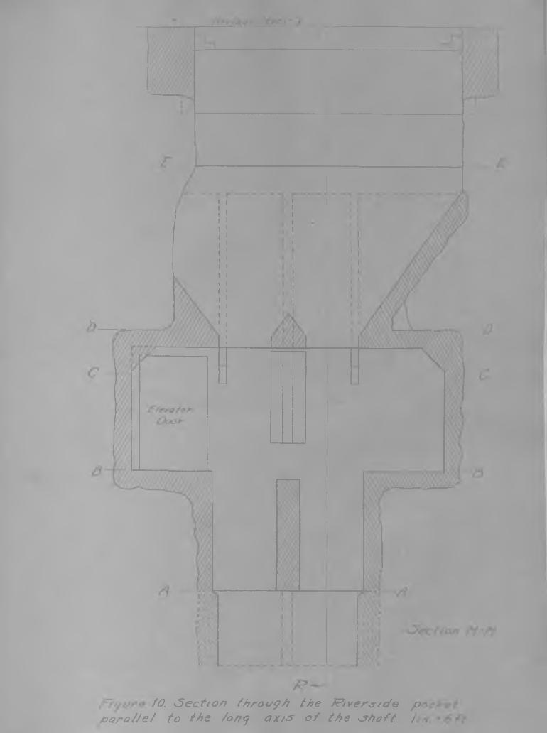
/O. ^ect/on throe/9/7 the ttver^/de p- /oarattet to the /ony ax//* of the <?hoft, / 7

56
panel, leading gatea, and other meehanlcal equipment (3) the lower room, containing the measuring hoppers and skiploading chutes. The operating room,may he entered either from the elevator compartment, or from either skip.compartr msnt # - , , , \
Before the shaft was concreted toe ground was remved to about 6 ft. south of toe south wall of the shaft throughout the vertical extent of the pocket. After the shaft concrete was in place the excavation was begun from the haulage level using this channel next to the shaft to break to* fhe four heavy concrete beams at the top of the pocket were formed and poured as soon as the excavation was deep enough to permit. These beams served as the collar of the pooket , and furnished support for the grizzlies and tipple. This done, the excavation was completed.
Concreting was begun at the bottom.The form plan was carefully worked out in advance so that all form lumber could be out in the carpenter shop. Each piece was marked and sent down ready to be nailed into place. The supports for the form cons: tited of heavy timber sets, framed in advance, and so designed that as the work progressed the sets were built up as a continuous structure.
, , : The concrete was poured in five stage#,construction joints between potirs being located so as to least impair the strength of the structure. The first pour
37
was small, Including only the floor of the lower chamber and the sloping chute bottoms, that is, up to section A-A In figures 9 and 10. When this pour had set the forms mere built up to the floor level of the middle chamber or operating room, and the concrete was poured to that level (B-B).
Each step of the construction involved the locating of numerous anchor bolts for supporting the future steel work and mechanical equipment, and for this reason careful engineering was necessary. A base-line was established by two points set in the roof above the excavation, After each pour the engineers dropped plumb-lines from these points, and transfered the base-line to batterboards nailed to plugs in the rook walls. Pro* this line other points were established on the batterboards so that chalk- lines could be strung to locate all features in connection with that pour. Bench marks were set as conveniently as possible for measuring vertical distances.
Great care was excerclsed to insure a good bond at the construction joints. Besides the usual precaution of making the mixture first poured on the joint richer and wetter than the main part of the pour, the first few inches of concrete was thoroughly agitated by moans of a blowpipe and compressed air. When the blowpipe could not be introduced from the top of the form, holes were bored through the form at close intervals along the joint, and the

38
blowpipe was Inserted throxigh them. By this procedure joints were obtained that were almost imperceptible after the form was removed. ,
When the concrete had been poured b the elevation C-C a plank floor was laid to serve as the lower form of the roof of the control room. It was believed that there would be some settling of this floor due to the weight of the large quanlty of concrete that.it must support. It was very necessary that this roof be at the exact elevation called for in the designs in order to properly locate mechanical equipment to be suspended from It. Mo data were at hand for estimating the amount of settling that might take place, but it was believed that raising the.form s inch would compensate for it. This proved to be an accurate estimate, and no difficulty was experienced when the machinery was installed.
39
PNEUMATIC PLACING GENERAL DISCUSSIONThe development of the art of placing
concrete by means of compressed air has greatly broadened the scope of underground construction. By this method concrete can be placed efficiently and economically In places that would have been considered Inaccessible for any other method of placing. The mixing plant can be located where most convenient, for It Is easily possible to place concrete 2500 ft. from the machine. A case has been recorded In which shots up to 4950 ft. were made. Shots greater than 1000 ft. should, however, be avoided except In unusual circumstances for It will be readily recognised that as the length of the shot Increases, the cost of compressed air becomes propor-
, tlonally greater.V- : .. , * V.. < - :
In the lining of railroad tunnels and subways under traffic pneumatic placing has become almost universal since no equipment Is needed inside the tunnel except the forms and a 6-lnch conveyor pipe. But in addition to the flexibility of this method, there Is another very Important advantage. By the old method of hand placing wherein the mixed concrete is dumped on a platform and shoveled Into place, it is impossible to secure a dense concrete, especially overhead as In the roof of a tunnel.

40
regardless of how carefully the tamping is done. Whereas concrete placed pneumatically develops greater strength than when placed by any other method.
The process has been especially valuable in mine work since the usual mine opening is relatively small. Few mine tunnels are large enough^ te accommodate even a small mixing plant. When the pneumatic method is used the concrete can often be mixed on the surface, dropped down the shaft in a vertical pipe, drawn into the placer, and shot directly into the forme. When the work is so far from the shaft as to be beyond the economic range of the placer other plans must be arranged. In praetleally all eases observed by the writer important structures have W e n within placing range of the shaft.
PLACIWO MACHINESThe first attempt to develop a concrete-
placing machine resulted in the construction of a mechanical bucket-conveyor type of plaeer. This machine proved to be such a complete failure that even the idea was abandoned without further consideration. Almost coincident with the failure of this first attempt a vertical pneumatic tank was developed that would place concrete through an 8-lnch pipe in a satisfactory manner. This machine waa used for several years. The air consumption was excessive, and many attempts at improvements were made, all of which failed to give the
expected results in practice.The next Important advance was the dev
elopment of the horizontal type of placing machine. Three different types of horizontal placers have been developed, all of which have been used to some extent. One of these consists of a horizontal cylinder with an opening at the top for charging; the discharge end tapers down to a 6-inch pipe connection. In the opposite end there is a piston of the same diameter as the Inside of the cylinder. After charging, the piston is thrust forward by compressed air, pushing the concrete toward the discharge end. When the piston has passed the door opening, effectively sealing the forward chamber, air is applied at a point a short distance back of the discharge end of the machine, and tho concrete Is forced out.The piston Is then moved back of the door opening, and the cycle repeated.
Another placer of the horizontal type has a charging door at the top and a series of pipes or jets along the Inside floor of the tank. These pipes<vary in length, and keep the eoncrete feeding toward the discharge end. This machine is known as the Webb placer.
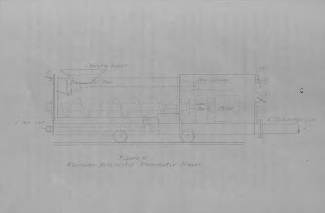
The most important advance in the design of concrete placers have been the features covered by the Ransome patents, The Ramsome placer consists of a horizontal cylinder having a spiral conveyor extending the full length of the chamber, (see fig.11) The screw or spiral conveyor.
41
4*ro
43
rotated by an electric or air motor, feeds the concrete into the discharge pipe at a rate calculated to give the maximum output, that is, as much as the air earn take away without danger of blocking the line« The screw conveyor also overcomes the inertia of the concrete, thus decreasing the amount of air required to start the batch In motion. The Ransome horisontal placers are made in two sises, one having a capacity of 7 cu. ft. per shot, the other 14 ou. ft. The screw Is operated by either an electric or a compressed air motor. The machines of both sises are equipped with a 6-inch discharge line, and will handle aggreate up to li-inoh stone or gravel.
The operation of the machine is simple• After charging the chamber to the proper level the door is washed off with water, and closed by an air cylinder operated by the four-way valve B (see fig.11). The main air valve 0 is then opened by the lever D, and immediately afterward the conveyor is started. When the air pressure shown by the gauge E begins to drop rapidly the batch has been discharged, the motor is stopped, and the main air valve closed. The charging door can then be opened by the valve B, and the machine is ready for the next charge. If the pressure fails to fall after the usual interval of time it is an indication that the line is blocked, and immediate steps should be taken to find and clear the obstruction. The procedure for clearing the line is the same as that described

44
earlier in this paper in connection with shaft concreting.The discharge line should be laid hori
zontally or inclined upward. If the pipe inclines downward the concrete settles to the lower side of the pipe, and permits the air to pass over it. If conditions require that the pipe be run with a downward slope, satisfactory results can often be obtained by introducing into the line at regular intervals, sections of pipe bent in the form of a U similar to expansion joints. These sharp bends aid the air In picking up any concrete that may have settled to the bottom of the pipe.
The air consumption of pneumatic placers depends on the size and length of the discharge line and on the vertical range of placing. The table on page 48 has been compiled by the writer to show the approximate air consumption of the Ransome horizontal placer when the elevation of discharge does not excede 20 ft. above the placer. So opportunity has been available for obtaining data for higher elevations.
The lower table on page 45 has been compiled from data obtained during the concreting of the Richmond Tunnel in San Francisco and in the St. Louis water works tunnel for the Mcliehael type vertical placer.
In order that sufficient air bo available at the desired instant, it is usually necessary to provide an air receiver near the placer. The size of the receiver

AIR CONSUMPTION OF RANSOMS 7 CU . FT . HORIZONTAL PLACER
Length of shot (ft.) 100 200 500 800 1000 1200 1600 2000 2500Air, cm.ft.per shot# 130 260 650 1040 1300 1560 1950 2600 3300Time, shooting (see) 10 15 25 40 so 60 75 100 126Time, loading (see) 30 30 30 30 30 30 30 30 30Time per shot (see) 40 45 55 70 : 80 90 105 130 156Shots per minute 1.6 1.3 1.1 .85 .75 #, .57 .46 .39Shots per hour • 90 80 65 61 45 40 34 28 23Air required (cu.ft. •v per minute)#
196 350 700 900 980 1040 noo 1200 1260Cu. yds. per hour 23 20 17 13 11 10 9 7 6
AIR CONSUMPTION 1C MICHAEL TYPE VERTICAL PLACER
Length of shot (ft.) 100 200 500 800 1000 1200 1500 2000 2500Shots per hour 120 108 78 60 61 46 36 27 24Cu. yds. per hour 40 36 26 5 ) 17 16 12 9 8Air required (cu.ft.
per minute)## Free
400
air,
720 1300
pressure at
1600
machine
1700 1800
100 pounds.
1840 1840 2000

46
depends, of course, on the amount of free air required per minute and on the local conditions of transmission. The makers of the placer reccommend a receiver capacity of about one-seventh of the free air required If the placer Is within 100 to 200 ft. of the compressor, or two-sevenths If the: i ' ; - :placer Is 1000 ft. from the compressor.
* Ordinary steel pipe Is usually used forthe discharge line. The greatest amount of wear occurs at the bends. Ordinary 6-lnoh pipe bends wear through In passing 400 to 600 cu. yds. of concrete. Standard cast-ironTr-: . . ; j- . ' - - , .elbows and fittings wear through so rapidly as to be practically useless. Cast manganese-steel elbows will often pass several thousand cubic yards without wearing through. Bends made with 45 degree laterals, having one straight branch plugged, have very long life especially if the plugged branch is filled with hard concrete. Bends made with a piece of special pneumatic hose are especially resistant to wear.
In straight runs ordinary 6-inch pipe will pass from 4000 to 5000 cu. yds. before wearing through. Flange connections have a longer life than threaded sleeve for reasons stated earlier In this paper (p.24), and are more easily disconnected in case the line becomes blocked.The writer considers it advisable to lay the discharge line in as long straight runs as possible, changing the direction by short bends rather than long sweeping bends, thus confining the maximum wear to relative short sections. Pit-run

gravel causes the least wear, crushed stone the most.The following data are results obtained
by experiments, conducted by the Pneumatic Placing Co., to determine the relative wearing qualities of different kinds of pipe:
Kind of pipe . Concrete passed Cost -Spiral-rivited pipe, 8-in. SO© cu.yds. 12^ per ou.yd.Lock-joint pipe, 8-lh, H 12^ "English seamless, steam tubing 10000 8 4^ *Oil well casing 18000 8 8}/ 8
47
Prom these results it is evident that the lowest cost per ou.yd. of concrete placed is obtained by using the highest grade of pipe. This is true, however, only if the maximum yardage is transported. When smaller quantities are to be placed cheaper costs would be obtained using a lower grade of pipe.
Pneumatic concrete placing is a patented process controlled by the lansome Concrete Machinery Co.The machines are not ordinarily for sale, but are leased on a per diem basis, or on the basis of cubic yards of concrete placed.

48
TUNNEL LININGThe pneumatic process for placing con
crete has its most important application in the lining of tunnels. Although, as yet, concrete has not been used extensively to line mine tunnels, its use is increasing rapidly at the present time to replace timber in Important permanent haulage-ways. In mines where swelling ground is a serious handicap in maintaining haulage drifts the use of concrete lining has practically eliminated the exorbitant cost of maintaining timbered drifts and the continual delays caused by accidents and obstructions.
In the ideal ease concreting is continuous with the driving of the tunnel, or the work may be done in cycles of alternately driving and concreting. As in shaft work there is a decided advantage in the use of some type of collapsible form, which may either consist of panels bolted together or be of the expanding type. The panel type of form is more satisfactory in mine work as the tunnels are usually small, seldom over 8 by 8 ft., and the project is not apt to be large enough to absorb the cost of more elaborate equipment. The panels may be made of either steel or wood, depending on the required life of the form. The expanding type of
form, mounted on carriages or trucks, is used extensively for lining railroad tunnels and subways. The floor or lower segment is always concreted first, whether the cross-section

49
of thd finished tunnel be cireular or reetangular. When til® floor has aot tho nail mid arch form la ereeted bn it, or la the case of large tnnnola where expanding forma are used, a track Is laid on the floor, and the whole form Is rolled forward as a unit, jacked Into place and blocked. One end of the form overlaps the flatahed concrete a fbn Inches, the open end la sheathed to the rock with planks; all remaining openings are carefully chinked with rags or sand bags. The delivery pipe from the concrete placer is inserted into the form at the highest point of the arch so that it projects about 6 Inches beyond the inner side of the bulkhead.Figure 12 illustrates a typical example in which steel-panel forms aro being used. Section R-R shows the floor concrete in place and a section through the steel form.
Before beginning to place concrete the delivery pipe should be thoroughly lubricated by shooting one or two sloppy batches of neat cement and water. The same precautions should be observed for getting a good bond between the walls and floor as were discussed in connection ' with shaft-station lining. Concrete should be delivered as long as it can be forced into the form> that is, until the air pressure recorded on the gauge at the placer does not fall after the usual interval of time, showing that the bateh has not been completely discharged. The pressure should be maintained in the line for a short period, and whenever
possible It Is desirable to wait until the eenepste has taken its initial set before removing the delivery pipe or otherwise disturb the form.
In small mine tunnels, sections 8 to 12 feet long work best, that is. In an 8 by 8 ft. tunnel 12 ft. is the maximum length of section that can be satisfactorly poured. In tunnels of smaller eroes-section shorter sections must be used. Sections up to 36 ft. long are poured in large railroad tunnels and subways. The writer believes that sections under 20 ft. in length are preferable even in the largest tunnels.
When drifting through loose or swelling ground it la usually necessary to timber the tunnel as soon as the ground is removed, and it Is not always possible to remove this timber, leaving the ground unsupported, while the lining is being installed. For this reason, the style of sets should he selected that will best lend themselves to the future concreting operations. By the proper foresight in timbering, the operation of concreting can be greatly simplified. The timber sets should he so designed that the outside of the timber will conform as nearly as possible to the section of the desired tunnel. The spacing of the sets is also important. Unless the ground is unusually bad two sets can be lined in each pour. The distance between the sets should be selected with this in mind.

51

52
The lagging la removed free the sets to be concreted, and the ground dug away to make room for the concrete. As the excavation progresses the ground is caught up with back-lagging supported by short struts from the sets as Is shown In figure 15. If the ends of these struts are placed on small pre-east concrete blocks rather than directly against the set they will not be exposed In the finished tunnel. As soon as the excavation is finished the reinforcing steel can be tied into place,.and the Inside form built. The lagging for the Inside form is cut to fit between the sets, and Is held in place by scabs nailed to the sides of the timbers (see fig.13). The outside of the lagging is placed flush with the outside edge of the timber sets. When the open end of the form has been bulkheaded the section is ready to pour. , ' - . -
A small unfilled segment usually remains at the crest of the arch, and it Is the usual practice to place short lengths of if-inch pipe so that one end extends up into the high place in the roof which will remain unfilled, the other end projects through the. roof of the tunnel. These pipes should be spaced about 25 ft. apart. When the concrete lining has thoroughly set a mixture of fine sand, cement, and water is injected through these pipes by means of a high-pressure grout gun until the open space is completely filled. Water-bearing horizons can be completely sealed by injecting grout in this manner.
S3
STATION LINIMA deeerlption of the methods employed
In lining the main pump station In the Riverside mine will Illustrate praotlcally every phase of this type of under- ground eonstruetlon. This station is a rectangular room, 60 by 20 fti with a clear height of 18 ft. It was constructed to house the main mine-pumps on the 637-ft. level. The roof Is flat, end Is divided Into three panels, whieh are reinforced by four concrete beams. The station Is entered from the level above through a shaft equipped with a small automat 1 ©elevator. At the time of concreting, the station was connected withthe main shaft by a short drift, which was later closed by a 15-ft. concrete bulkhead. The discharge pipes passed out to the ^aft through this bulkhead. The suction pipes entered through a similar bulkhead at the opposite end of the station.
The excavation was crossed by several fissures which made the back somewhat bloeky. It was necessary to provide support for parts of the back until the concrete had developed sufficient strength to take the lead. An overhead crane was installed for handling the pumps and motors. The erane-ralls were supported by four steel sets, fabricated from 6-inoh I beams. The service shaft off the north side of the station was concrete lined before work on the station lining was begum.

WALL COBSTRUCTIOHAs soon as the excavation was complete
the engineers established; a permanent baseline on concrete monuments set In the floor, and located the principal features of the structure by means of batterbcards. The piers for the support of the steel work were then poured, and the four steel sets were erected upon them. The columns were located ,so that the inner flanges coincided with the surface of the side-walls, thus furnishing the outside support for the wall forms. The walls were poured in two sections, W1 and W2 in figure 14. The forms were constructed of 2 by 10- ineh boards, laid against the steel columns, and braced by sets framed from 10 by 10-inch timbers. Bulkheads wore built at the construction joint marked by the line between sections Wl and W2 in figure 14.
The concrete was placed in the walla and roof pneumatically. The concrete placer was installed in a drift adjoining the shaft. The concrete was mixed at the surface, dropped down the shaft, caught In an improvised hopper from which it was drawn into the placer. When pouring the walls the concrete was shot to a receiving hopper which was about centrally located near the top of the excavation. From the receiving hopper the eencrete flowed in troughs to both sides of the form.
The receiving hopper used here consists

f ig u re /*?. FD/a n <?how i ny arrangement o f de/ivery pipe, receiving hopper and troughs for pouring station rvat/s.
x5<f< W2 J5ec Wt
m , V'AF l y u r e /.T. E /e r a i io n uhoynm y a r r a n g e m e n t o f d e / t r e r y p t p e ,
r e c e iv e n<y hopper^ a n d tro u g h s f o r p o u r in g a t a t to n w a / ls .
- ^ec £?/ Jec. P J ^ec fd Jec /PZ
lii-'T;^ LI T-i j 4.
/' I .- — ^ . y 4. .. -I 4 ^
f ig u re /6 . Elevation showing the arrangement o f ctetivory p ip 6 f ° r pouring station roof

#6
of a rectangular steel box, 2 by 3 ft. and 2 ft. high.(see fig.17) In one end there Is a circular opening for inserting the end of the delivery pipe, the other end is reinforced by several pieces of angle-iron. Two-inch angles around the Inside, top edges of the box provide a shelf to support a cover made of 2-inch planks. The concrete is discharged through two openings, 6 inches square, in the sides of the box. These openings are provided with short spouts, under which the troughs are hung. The box should be rigidly constructed from one-eighth or three-sixteenths-inch plate as the concrete is shot into it with considerable force.The hopper must also be blocked firmly into place by struts from all sides.
The plan, figure 14, and the elevation, figure 15, Illustrate the location of the receiving hopper and the arrangement of the troughs and delivery pipe for pouring each of the two sections. The walls were poured to about a foot below the bottom edge of the roof-beams. Other details of the procedure have been fully covered in preceding discussions.
ROOF COMSTRUCTIOlThe roof was poured in four, sections,
the construction joints were made as nearly midway between the beams as conditions would permit. The approximate position of each construction joint is shown in figure 16,

57
. . j
c o o
^cyt/re /7.J?ece<vtn<f /r a p p e r c/sec/ yv<tJr p /?f(//rr4 f t ci/7 joottrtnj ofafwn rta //j.
p/acer

58
fhe form was construe feed fer only the section immediately to be poured. As the stulle supporting the back were removed the weight was transfered to the f o m by the use of pre-east Concrete blocks placed directly on the form, rod filled out at the upper end with wooden blocks rod wedges. It was usually possible to locate these blocks directly over the sets supporting the forms, but when this was not possible an additional atull was placed from the floor to the point on the form directly under the block.
Figure 16 shows the arrangement of the delivery pipe for pouring each of the four sections. Section R1 was poured first. All of the longitudinal reinforcing bars for the entire panel were laid in place, the free ends projected through the bulkhead. The bulkhead was built up as the form was filled so as to permit inspection and puddling. There is always more or less separation of the aggregates as the concrete is shot out of the delivery pipej the pebbles are thrown the farthest, whereas the finer material falls closer to the end of the pipe. To prevent this happening, a 10-ft. length of pipe was slipped over the end of the delivery pipe to carry the concrete to the far end of the section. As soon as the reinforcing steel was oomplet- ly buried the pipe was removed.
Section R2 was next poured, followed by R5. The final section, R4, was poured from the shaft at the

m
aide of the station. The hack over this section was excavated a little higher than over the other sections so as to give room for the men to work above the reinforcing steel. The delivery pipe was laid In the shaft, and entered the form through a short 90 degree bend.
As In tunnel lining It Is Impossible to completely fill up to the rock back, but If short pipes are Inserted at advantageous points all the remaining cavities can be shot full of grout after, the concrete has set.

60
BIBLI00RAP1Y(1) Mills, C. E., Eng. and Min. Jour., vol. 130, p. 699,
1930.(2) Concrete Shaft Lining; Eng. and Cent.; vol. 45, p. 144,
1916 i(3) Concrete Lining of the Kingdon Shaft, Eng. and Min.
Jour., vol. 95, p. 177, 1913.(4) Banghart, M. D., Shaft Concreting at Zaruma, Ecuador,
Eng. and Min. Jour., vol. 130, p. 277, 1930.(5) DeCamp, W. V., Ring Method of Shaft Concreting, Eng.
and Min, Jour., vol. 121, p. 329, 1916.(6) Gardner, R. D., Chief Consolidated Shaft at Eureka,
Utah, Eng. and Min. Jour., vol. 110, p. 460, 1920.(7) Stovel, J. H., Pyne and Songo Shafts, Eng. and Min.
Jour., vol. Ill, p. 698, 1921.(8) Sacramento Shaft at Blebee, Min. and Sol. Press,
Oct. 7, 1916.

3 iLE1711. 1135 -3 5 C5
a 3 9 0 0 1 6 0 1 2 7 8 2 106