The Use of a Solid State Analog Television Transmitter as a...
3
A 2 k m p t p U E t t t b p B ___________________________ *Work supported Wisconsin, Madi#[email protected]s THE USE A SU J. Kulp Abstract A solid state 200 MHz ope frequency (R superconductin consists of th and one moni employs rugg kilowatt draw maximum con power of the output through low level RF the 200 MHz phase. The Synch University of electron gun Electron Laser the electron g television tran through Tran station located system was ve frequency and before disasse The transmitte of a custom b power input superconductin TR The transm Series HT-30 Broadcast Com field effect tra amplifier draw full power ope The 30 kW one computer and two high outputs of th quadrature RF an RF circulato ________________ by DOE award D son. sc.edu E OF A SO UPERCON pin # , K. Klem R. e analog televi eration is bein RF) power am ng electron g ree separate R itor and contr ged field effec ers that are in ntinuous power transmitter sy h a standard c system is emp signal and pre INTROD hrotron Radiat Wisconsin is d suitable as th r (FEL) [1]. T gun is being nsmitter . The nscom, Corpor d on Peavine erified to oper d fully tested to embling and sh er was reassemb built room to p and radio fre ng electron gun RANSMITT mitter system i HS analog u mmunications ansistors (FET wers that allow eration [4]. W system consi control system power 15 kW he cabinets c hybrid combin or to the superc E-SC0005264, and OLID STA NDUCTIN man, Synchr . Legg, Jeffe ision transmitt ng commission mplifier on t gun cavity. RF power com rol cabinet. T ct transistors ndividually ho r output. The ystem is 30 kW coaxial transm ployed to digit ecisely control DUCTION tion Center developing a s he injector for The RF power provided by e transmitter ration from Mountain, Ne rate at the cor o 25 kW at the hipping the un bled at the SRC provide adequ equency transm n cavity [3]. TER SYSTE is a solid stat nit manufactu Division. Th T’s) built into w swapping in ists of four ca m, one driver am W RF amplifier combine with ner that directs conducting RF d the University o ATE ANA NG ELEC rotron Radia Stoughton, erson Lab, N ter designed fo ned as a radi the Wisconsi The amplifie mbiner cabinet The transmitte built into on ot swappable a total combine W at 200 MH mission line. A tally synthesiz l amplitude an (SRC) at th uperconductin r a future Fre required to ru a used analo was purchase the KRXI-TV evada [2]. Th rect power an e mountain sit nit to the SRC C facility insid ate air cooling mission to th EM te Platinum II ured by Harri he system use 1 kW modula n or out durin abinets housin mplifier cabine r cabinets. Th h an outboar s power throug F gun cavity [5] f ALOG TEL TRON GU ation Center, WI 53589, U Newport New or o n er ts er ne at d Hz A ze nd he ng ee un g d V he nd te C. de g, he II is es ar ng ng et he rd h ]. All RF p transmiss of the tran The en 15 kW po ac and de used to po Figu The am class A a amplifier the pre-a amplifier paralleled combined This prov each amp the 3dB h output po the ampli The p controlled standing Comp Contr Cabin 1KW Amplifi Drawer 17-way Geysel Combin 15KW Power Suppli LEVISION UN POWE , University USA ws, VA 23606 power is tran sion line. Figu nsmitter system ntire system is ower supplies eliver 50 volts ower the RF am ure 1: Front and mplifier driver amplifier stage block. The dr amp outputs a modules. T d class AB bl d by a 17-way vides the total o plifier cabinet. hybrid RF com ower. Figure 2 fier chain. phase and ga d with a mecha wave ratio puter rol net ier rs y ners W r ies N TRANS ER AMPL of Wisconsi 6, USA nsmitted throug ure 1 shows a m. powered with that operate o s dc at 300 am mplifiers in eac d back view of r modules co es which drive rivers are used and drive the The power am locks that are ay Geysel Net output of 15 kW These in turn mbiner to make 2 shows a bas ain of the c anical phase sh (VSWR) i SMITTER LIFIER* in-Madison, gh standard c front and back h six Basler E on three phase mps. These un ch cabinet. f RF transmitte ontain two cas a parallel cla primarily to am e 1 kW RF mplifier modul e summed and twork combine W of RF powe n are combine e 30 kW of to sic block diagr ombiner syste hifter and the v is monitored R AS coaxial k view Electric e 208V nits are r. scaded ass AB mplify power es are d then er [6]. er from d with otal RF ram of em is voltage with THPPC071 Proceedings of IPAC2012, New Orleans, Louisiana, USA ISBN 978-3-95450-115-1 3452 Copyright c ○ 2012 by IEEE – cc Creative Commons Attribution 3.0 (CC BY 3.0) — cc Creative Commons Attribution 3.0 (CC BY 3.0) 07 Accelerator Technology and Main Systems T08 RF Power Sources
Transcript of The Use of a Solid State Analog Television Transmitter as a...
A
2
kmp
tp
U
Ettt
b
p
B
____________________________
*Work supported Wisconsin, Madis#[email protected]
THE USEA SU
J. Kulp
Abstract A solid state
200 MHz opefrequency (Rsuperconductinconsists of thand one moniemploys ruggkilowatt drawmaximum conpower of the output throughlow level RF the 200 MHz phase.
The SynchUniversity of electron gun Electron Laserthe electron gtelevision tranthrough Transtation locatedsystem was vefrequency andbefore disasseThe transmitteof a custom bpower input superconductin
TRThe transm
Series HT-30Broadcast Comfield effect traamplifier drawfull power ope
The 30 kWone computer and two high outputs of thquadrature RFan RF circulato
________________
by DOE award Dson. sc.edu
E OF A SOUPERCON
pin#, K. Klem
R.
e analog televieration is bein
RF) power amng electron gree separate Ritor and contr
ged field effecers that are in
ntinuous powertransmitter sy
h a standard csystem is empsignal and pre
INTRODhrotron RadiatWisconsin is dsuitable as thr (FEL) [1]. Tgun is being nsmitter. The
nscom, Corpord on Peavine erified to oper
d fully tested toembling and sher was reassembbuilt room to pand radio freng electron gun
RANSMITTmitter system i
HS analog ummunications ansistors (FETwers that alloweration [4].
W system consicontrol systempower 15 kW
he cabinets c hybrid combinor to the superc
E-SC0005264, and
OLID STANDUCTIN
man, Synchr
. Legg, Jeffe
ision transmittng commissionmplifier on tgun cavity. RF power comrol cabinet. Tct transistors ndividually hor output. The
ystem is 30 kWcoaxial transmployed to digitecisely control
DUCTION tion Center developing a she injector forThe RF power
provided by e transmitter ration from Mountain, Nerate at the coro 25 kW at thehipping the unbled at the SRCprovide adequequency transmn cavity [3].
TER SYSTEis a solid statnit manufactuDivision. Th
T’s) built into w swapping in
ists of four cam, one driver am
W RF amplifiercombine withner that directsconducting RF
d the University o
ATE ANANG ELEC
rotron RadiaStoughton,
erson Lab, N
ter designed foned as a radithe WisconsiThe amplifie
mbiner cabinetThe transmittebuilt into on
ot swappable atotal combine
W at 200 MHmission line. A
tally synthesizl amplitude an
(SRC) at thuperconductin
r a future Frerequired to rua used analowas purchasethe KRXI-TV
evada [2]. Thrrect power ane mountain sitnit to the SRCC facility insidate air coolingmission to th
EM te Platinum IIured by Harrihe system use1 kW modula
n or out durin
abinets housinmplifier cabiner cabinets. Thh an outboars power througF gun cavity [5]
f
ALOG TELTRON GU
ation Center,WI 53589, U
Newport New
or o n
er ts er ne at d
Hz A ze nd
he ng ee un g d V he nd te C. de g, he
II is es ar ng
ng et he rd h ].
All RF ptransmissof the tran
The en15 kW poac and deused to po
Figu
The amclass A aamplifier the pre-aamplifier paralleledcombinedThis proveach ampthe 3dB houtput pothe ampli
The pcontrolledstanding
CompContrCabin
1KW AmplifiDrawer
17-wayGeysel Combin
15KWPower Suppli
LEVISIONUN POWE
, University USA
ws, VA 23606
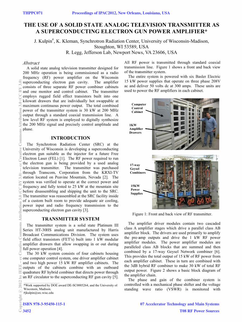
power is transion line. Figunsmitter system
ntire system is ower supplies eliver 50 voltsower the RF am
ure 1: Front and
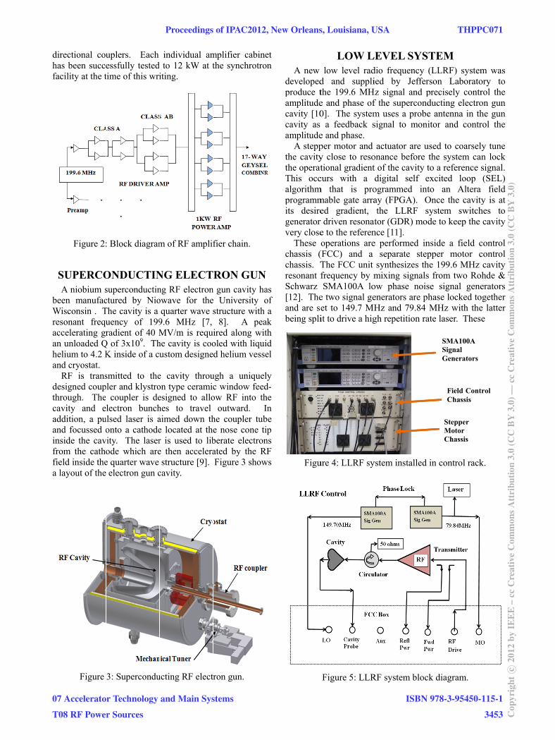
mplifier driveramplifier stage
block. The dramp outputs a
modules. Td class AB bld by a 17-wayvides the total oplifier cabinet. hybrid RF comower. Figure 2fier chain.
phase and gad with a mecha
wave ratio
puter rol net
ier rs
y
ners
W r ies
N TRANSER AMPL
of Wisconsi
6, USA
nsmitted througure 1 shows a m.
powered withthat operate o
s dc at 300 ammplifiers in eac
d back view of
r modules coes which driverivers are used and drive the
The power amlocks that are
ay Geysel Netoutput of 15 kW These in turn
mbiner to make2 shows a bas
ain of the canical phase sh
(VSWR) i
SMITTERLIFIER*
in-Madison,
gh standard cfront and back
h six Basler Eon three phase
mps. These unch cabinet.
f RF transmitte
ontain two cas a parallel claprimarily to am
e 1 kW RF mplifier module summed andtwork combineW of RF powen are combinee 30 kW of tosic block diagr
ombiner systehifter and the vis monitored
R AS
coaxial k view
Electric e 208V nits are
r.
scaded ass AB mplify power es are d then er [6].
er from d with
otal RF ram of
em is voltage
with
THPPC071 Proceedings of IPAC2012, New Orleans, Louisiana, USA
ISBN 978-3-95450-115-1
3452Cop
yrig
htc ○
2012
byIE
EE
–cc
Cre
ativ
eC
omm
onsA
ttri
butio
n3.
0(C
CB
Y3.
0)—
ccC
reat
ive
Com
mon
sAtt
ribu
tion
3.0
(CC
BY
3.0)
07 Accelerator Technology and Main Systems
T08 RF Power Sources
h
bWr
h
t
directional couhas been succefacility at the t
Figure 2:
SUPERCOA niobium s
been manufacWisconsin . Tresonant frequaccelerating gran unloaded Qhelium to 4.2 Kand cryostat.
RF is transdesigned coupthrough. Thecavity and eaddition, a puand focussed oinside the cavfrom the cathofield inside thea layout of the
Figure
uplers. Each essfully testedtime of this wri
: Block diagram
ONDUCTINsuperconductinctured by NioThe cavity is a uency of 199radient of 40 M
Q of 3x10⁹. ThK inside of a cu
smitted to thepler and klystro coupler is delectron bunch
ulsed laser is aonto a cathode
vity. The laserode which aree quarter wave electron gun c
3: Supercondu
individual amto 12 kW at t
iting.
m of RF amplif
NG ELECTng RF electronowave for thequarter wave s
9.6 MHz [7, MV/m is requhe cavity is cooustom designe
e cavity throuon type ceramicesigned to allohes to travel aimed down the located at ther is used to libe then accelerastructure [9].
cavity.
ucting RF elect
mplifier cabinethe synchrotro
fier chain.
RON GUNn gun cavity hae University ostructure with
8]. A peaired along witoled with liquid helium vesse
ugh a uniquelc window feedow RF into th
outward. Ihe coupler tube nose cone tiberate electronated by the RFFigure 3 show
ron gun.
et n
as of a
ak th d el
y d- he n
be p
ns F
ws
A new developedproduce tamplitudecavity [10cavity as amplitude
A steppthe cavitythe operatThis occalgorithmprogrammits desiregeneratorvery close
These chassis (chassis. Tresonant fSchwarz [12]. Theand are sbeing spli
Figu
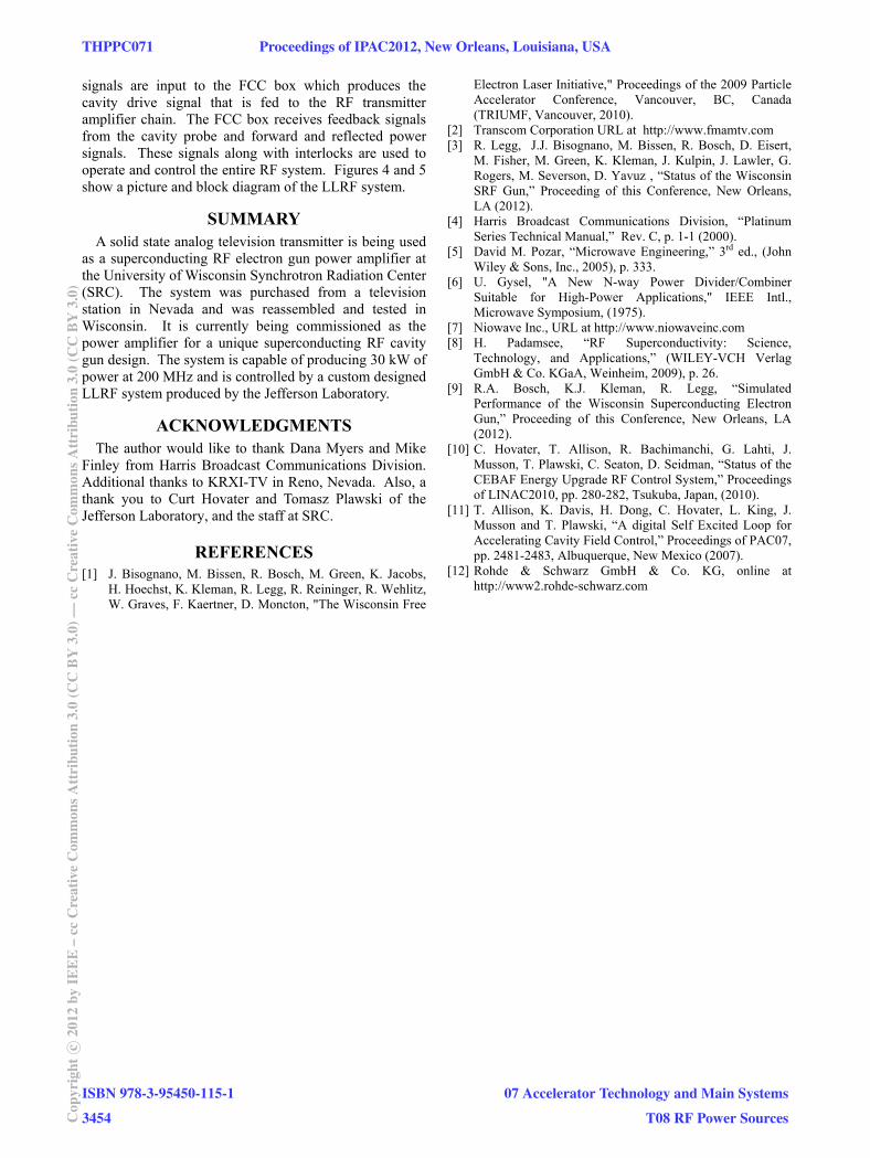
LOW Llow level rad
d and supplithe 199.6 MHe and phase of0]. The system a feedback se and phase. per motor and y close to resotional gradient
curs with a m that is promable gate arraed gradient, r driven resonae to the referenoperations are(FCC) and a The FCC unit frequency by mSMA100A lo
e two signal geet to 149.7 MHit to drive a hig
ure 4: LLRF sy
Figure 5: LLR
LEVEL SYSdio frequency ied by Jeffer
Hz signal and pf the supercondm uses a probesignal to mon
actuator are uonance before t of the cavity tdigital self eogrammed intay (FPGA). Othe LLRF s
ator (GDR) monce [11]. e performed in
separate stepsynthesizes th
mixing signalsow phase noisenerators are pHz and 79.84 gh repetition ra
ystem installed
RF system bloc
STEM (LLRF) systemrson Laboratoprecisely contrducting electroe antenna in thitor and contr
used to coarselthe system cato a reference excited loop to an Altera
Once the cavitysystem switchde to keep the
nside a field cpper motor c
he 199.6 MHz s from two Rose signal gene
phase locked toMHz with the
ate laser. Thes
in control rack
ck diagram.
SMA100A Signal Generators
Field ContChassis
Stepper Motor Chassis
m was ory to rol the on gun he gun rol the
ly tune an lock signal. (SEL)
field y is at
hes to cavity
control control cavity
ohde & erators
ogether e latter e
k.
trol
Proceedings of IPAC2012, New Orleans, Louisiana, USA THPPC071
07 Accelerator Technology and Main Systems
T08 RF Power Sources
ISBN 978-3-95450-115-1
3453 Cop
yrig
htc ○
2012
byIE
EE
–cc
Cre
ativ
eC
omm
onsA
ttri
butio
n3.
0(C
CB
Y3.
0)—
ccC
reat
ive
Com
mon
sAtt
ribu
tion
3.0
(CC
BY
3.0)
signals are input to the FCC box which produces the cavity drive signal that is fed to the RF transmitter amplifier chain. The FCC box receives feedback signals from the cavity probe and forward and reflected power signals. These signals along with interlocks are used to operate and control the entire RF system. Figures 4 and 5 show a picture and block diagram of the LLRF system.
SUMMARY A solid state analog television transmitter is being used
as a superconducting RF electron gun power amplifier at the University of Wisconsin Synchrotron Radiation Center (SRC). The system was purchased from a television station in Nevada and was reassembled and tested in Wisconsin. It is currently being commissioned as the power amplifier for a unique superconducting RF cavity gun design. The system is capable of producing 30 kW of power at 200 MHz and is controlled by a custom designed LLRF system produced by the Jefferson Laboratory.
ACKNOWLEDGMENTS The author would like to thank Dana Myers and Mike
Finley from Harris Broadcast Communications Division. Additional thanks to KRXI-TV in Reno, Nevada. Also, a thank you to Curt Hovater and Tomasz Plawski of the Jefferson Laboratory, and the staff at SRC.
REFERENCES [1] J. Bisognano, M. Bissen, R. Bosch, M. Green, K. Jacobs,
H. Hoechst, K. Kleman, R. Legg, R. Reininger, R. Wehlitz, W. Graves, F. Kaertner, D. Moncton, "The Wisconsin Free
Electron Laser Initiative," Proceedings of the 2009 Particle Accelerator Conference, Vancouver, BC, Canada (TRIUMF, Vancouver, 2010).
[2] Transcom Corporation URL at http://www.fmamtv.com [3] R. Legg, J.J. Bisognano, M. Bissen, R. Bosch, D. Eisert,
M. Fisher, M. Green, K. Kleman, J. Kulpin, J. Lawler, G. Rogers, M. Severson, D. Yavuz , “Status of the Wisconsin SRF Gun,” Proceeding of this Conference, New Orleans, LA (2012).
[4] Harris Broadcast Communications Division, “Platinum Series Technical Manual,” Rev. C, p. 1-1 (2000).
[5] David M. Pozar, “Microwave Engineering,” 3rd ed., (John Wiley & Sons, Inc., 2005), p. 333.
[6] U. Gysel, "A New N-way Power Divider/Combiner Suitable for High-Power Applications," IEEE Intl., Microwave Symposium, (1975).
[7] Niowave Inc., URL at http://www.niowaveinc.com [8] H. Padamsee, “RF Superconductivity: Science,
Technology, and Applications,” (WILEY-VCH Verlag GmbH & Co. KGaA, Weinheim, 2009), p. 26.
[9] R.A. Bosch, K.J. Kleman, R. Legg, “Simulated Performance of the Wisconsin Superconducting Electron Gun,” Proceeding of this Conference, New Orleans, LA (2012).
[10] C. Hovater, T. Allison, R. Bachimanchi, G. Lahti, J. Musson, T. Plawski, C. Seaton, D. Seidman, “Status of the CEBAF Energy Upgrade RF Control System,” Proceedings of LINAC2010, pp. 280-282, Tsukuba, Japan, (2010).
[11] T. Allison, K. Davis, H. Dong, C. Hovater, L. King, J. Musson and T. Plawski, “A digital Self Excited Loop for Accelerating Cavity Field Control,” Proceedings of PAC07, pp. 2481-2483, Albuquerque, New Mexico (2007).
[12] Rohde & Schwarz GmbH & Co. KG, online at http://www2.rohde-schwarz.com
THPPC071 Proceedings of IPAC2012, New Orleans, Louisiana, USA
ISBN 978-3-95450-115-1
3454Cop
yrig
htc ○
2012
byIE
EE
–cc
Cre
ativ
eC
omm
onsA
ttri
butio
n3.
0(C
CB
Y3.
0)—
ccC
reat
ive
Com
mon
sAtt
ribu
tion
3.0
(CC
BY
3.0)
07 Accelerator Technology and Main Systems
T08 RF Power Sources