The Use Case Model -...
39
21 Chapter The Use Case Model ■ System Behavior ■ Actors ■ Use Cases ■ Use Case Diagrams ■ Activity Diagrams ■ Summary Quatrani.book Page 21 Monday, May 8, 2006 11:56 AM
Transcript of The Use Case Model -...

21
Chapter
The Use Case Model■
System Behavior
■
Actors
■
Use Cases
■
Use Case Diagrams
■
Activity Diagrams
■
Summary
Quatrani.book Page 21 Monday, May 8, 2006 11:56 AM

Quatrani.book Page 22 Monday, May 8, 2006 11:56 AM

SYSTEM BEHAVIOR 23
THE FUNCTIONAL REQUIREMENTS of a system under develop-ment (i.e., the functionality that must be provided by the system) are documented in a use case model that illustrates the system’s intended functions (use cases), its surround-ings (actors), and relationships between the use cases and actors (use case diagrams). At the same time, it is useful to see the flow of control and the flow of data between the dif-ferent scenarios represented in a use case. Activity diagrams are used to visually document the different flows in a use case.
SYSTEM BEHAVIOR
A.3.1
THE MOST IMPORTANT role of a use case model is one of com-munication. It provides a vehicle used by the customers or end users and the developers to discuss the system’s func-tionality and behavior. The use case model starts in the Inception phase with the identification of actors and princi-pal use cases for the system. The model is then matured in the Elaboration phase—more detailed information is added to the identified use cases, and additional use cases are added on an as-needed basis.
CREATING THE USE CASE MODEL
1. Right-click on the owning project in the Model Explorer and select New > UML Model.
2. Select Use Case Model.3. Accept the default name of Use Case Model.4. Click Finish.
This will add a use case model as shown in Figure 3-1.
Quatrani.book Page 23 Monday, May 8, 2006 11:56 AM

24 Chapter 3 / The Use Case Model
Use Case Model Template
A.3.2
IBM Rational Software Architect uses a model template when a new use case model is created. The template contains model elements that can be used to help you structure your model:
■ Overviews package
■ Use-Case Building Blocks package
■ Versatile Actors package
The Overviews package contains two default diagrams that are used to provide an overview of the system. The Actors overview is a visualization of the actors in the model. For small models, it could contain all of the actors in the model. For larger models, it may contain only some of the
Figure 3-1 Use Case Model
Quatrani.book Page 24 Monday, May 8, 2006 11:56 AM
SYSTEM BEHAVIOR 25
actors. The Context Overview diagram shows the “most important” use cases in your model. Again, for a small model this may be all of the use cases. For larger models, this dia-gram usually contains the architecturally significant use cases.
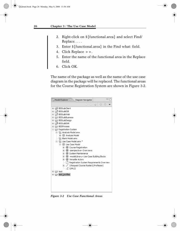
The Use-Case Building Blocks package contains model elements that can be copied to the use case model, allowing you to create model elements for your own use. The first element is a package called ${functional.area}, and this package contains a use case diagram. If you have a large model, you may want to group your use cases into func-tional areas. This is when you would use this building block. Grouping use cases into functional areas for smaller models is probably overkill. The second model element is called ${use.case}, which is a prototypical use case contain-ing optional activity and sequence diagrams. This model element can be used for all types of models. The nice part of using this building block is that the entire structure for a use case (use case, activity diagram, and sequence dia-grams) will automatically be created for you.
Sometimes an actor may communicate with use cases that are in different functional areas. That is where the Ver-satile Actors package comes into play since it contains those actors. This package contains one use case diagram that shows all of the actors that communicate with use cases that cross functional boundaries.
Functional Areas Packages
For the Course Registration System we have two functional areas: Course Registration and System Maintenance.
CREATING FUNCTIONAL AREA PACKAGES
1. Click Ctrl and drag the ${functional.area} package to the desired model location (in our case, we will drag it to the Use Case Model).
Quatrani.book Page 25 Monday, May 8, 2006 11:56 AM
26 Chapter 3 / The Use Case Model
2. Right-click on ${functional.area} and select Find/Replace. . . .
3. Enter ${functional.area} in the Find what: field.4. Click Replace >>.5. Enter the name of the functional area in the Replace
field.6. Click OK.
The name of the package as well as the name of the use case diagram in the package will be replaced. The functional areas for the Course Registration System are shown in Figure 3-2.
Figure 3-2 Use Case Functional Areas
Quatrani.book Page 26 Monday, May 8, 2006 11:56 AM
ACTORS 27
ACTORS
ACTORS ARE NOT part of the system—they represent anyone or anything that must interact with the system. An actor may:
■ Only input information to the system
■ Only receive information from the system
■ Input and receive information to and from the system
Typically, these actors are found in the problem state-ment and by conversations with customers and domain experts. The following questions may be used to help iden-tify the actors for a system:
■ Who is interested in a certain requirement?
■ Where in the organization is the system used?
■ Who will benefit from the use of the system?
■ Who will supply the system with this informa-tion, use this information, and remove this infor-mation?
■ Who will support and maintain the system?
■ Does the system use an external resource?
■ Does one person play several different roles?
■ Do several people play the same role?
■ Does the system interact with a legacy system?
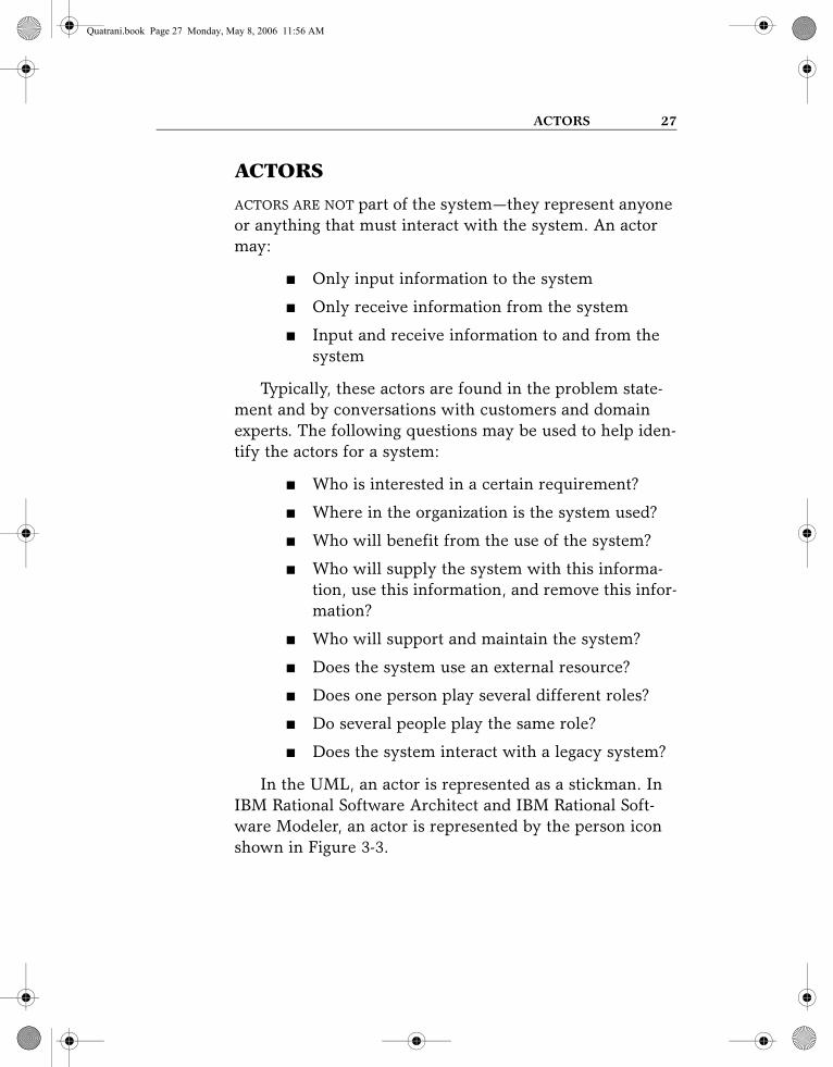
In the UML, an actor is represented as a stickman. In IBM Rational Software Architect and IBM Rational Soft-ware Modeler, an actor is represented by the person icon shown in Figure 3-3.
Quatrani.book Page 27 Monday, May 8, 2006 11:56 AM

28 Chapter 3 / The Use Case Model
What Constitutes a “Good” Actor?
Care must be taken when identifying the actors for a sys-tem. This identification is done in an iterative fashion—the first cut at the list of actors for a system is rarely the final list. For example, is a new student a different actor than a returning student? Suppose you initially say the answer to this question is yes. The next step is to identify how the actor interacts with the system. If the new student uses the system differently than the returning student, they are dif-ferent actors. If they use the system in the same way, they are the same actor. Another example is the creation of an actor for every role a person may play. This may also be overkill. A good example is a teaching assistant in the ESU Course Registration System. The teaching assistant takes classes and teaches classes. The capabilities needed to select courses to take and to teach are already captured by the identification of functionality needed by the Student and the Professor actors. Therefore, there is no need for a Teach-ing Assistant actor. By looking at the identified actors and documenting how they use the system, you will iteratively arrive at a good set of actors for the system.
Actors in the ESU Course Registration System
The previous questions were answered as follows:
■ Students want to browse the course catalog and register for courses.
Figure 3-3 Actor in Rational Software Architect
Quatrani.book Page 28 Monday, May 8, 2006 11:56 AM

ACTORS 29
■ Professors want to select courses to teach and request a course roster.
■ The Registrar must create the curriculum and generate a catalog for the semester.
■ The Registrar must maintain all the information about courses, professors, and students.
■ The Billing System must receive billing informa-tion from the system.
Based on the answers to the questions posed, the follow-ing actors have been identified: Student, Professor, Regis-trar, and the Billing System. Since the Student and the Billing System only deal with course registration, we will locate them in the Course Registration package. Likewise, the Registrar only deals with curriculum maintenance, so we will add the Registrar to the System Maintenance pack-age. The Professor is a different story. The Professor wants to request a course roster, which belongs to the Course Registration package, and the Professor also needs to select courses to teach, which belongs to the System Maintenance package. Since this actor interacts with use cases in differ-ent functional areas, we will add it to the Versatile Actors package.
CREATING ACTORS
1. Right-click on the owning package in the Model Explorer and select Add UML > Actor.
2. While the new actor is still selected, enter its name.
The actors for the ESU Course Registration System are shown in Figure 3-4.
Quatrani.book Page 29 Monday, May 8, 2006 11:56 AM
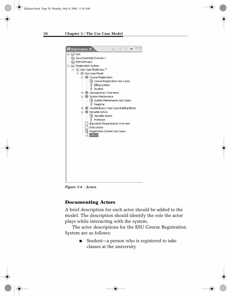
30 Chapter 3 / The Use Case Model
Documenting Actors
A brief description for each actor should be added to the model. The description should identify the role the actor plays while interacting with the system.
The actor descriptions for the ESU Course Registration System are as follows:
■ Student—a person who is registered to take classes at the university
Figure 3-4 Actors
Quatrani.book Page 30 Monday, May 8, 2006 11:56 AM

USE CASES 31
■ Professor—a person who is certified to teach classes at the university
■ Registrar—the person who is responsible for the maintenance of the ESU Course Registration System
■ Billing System—the external system responsible for student billing
DOCUMENTING ACTORS
1. Click to select the actor in the Model Explorer.2. Select the Properties tab. If this tab is not visible,
select Window > Show View > Properties to make it visible.
3. Select Documentation.4. Enter the description for the actor.
The documentation for the Student actor is shown in Figure 3-5.
USE CASES
USE CASES MODEL a dialogue between an actor and the system. They represent the functionality provided by the system, that is, what capabilities will be provided to an actor by the
Figure 3-5 Student Actor Documentation
Quatrani.book Page 31 Monday, May 8, 2006 11:56 AM

32 Chapter 3 / The Use Case Model
system. The collection of use cases for a system constitutes all the defined ways the system may be used. The formal definition for a use case is as follows:
A use case is a sequence of transactions performed by a system that yields a measurable result of values for a par-ticular actor.
The following questions may be used to help identify the use cases for a system:
■ What are the tasks of each actor?
■ Will any actor create, store, change, remove, or read information in the system?
■ What use case will create, store, change, remove, or read this information?
■ Will any actor need to inform the system about sudden, external changes?
■ Does any actor need to be informed about certain occurrences in the system?
■ What use cases will support and maintain the system?
■ Can all functional requirements be performed by the use cases?
In the UML, a use case is represented as an oval, as shown in Figure 3-6.
Figure 3-6 The UML Representation of a Use Case
Quatrani.book Page 32 Monday, May 8, 2006 11:56 AM

USE CASES 33
What Constitutes a “Good” Use Case?
Over the years there has been a lot of discussion dealing with the “goodness” of a use case. One problem that I have encountered is the level of detail found in use cases. That is, how big (or how little) should they be? There is no one, right answer. The rule of thumb that I apply is the following:
■ A use case typically represents a major piece of functionality that is complete from beginning to end.
■ A use case must deliver something of value to an actor.
For example, in the ESU Course Registration System, the student must select the courses for a semester, the student must be added to the course offerings, and the student must be billed. Is this three use cases, or just one? I would make it one because the functionality represents what happens from beginning to end. What good would the system be if a student was not added to the courses selected (or at least notified if the addition does not occur)? Or if the student was not billed? (The university would not stay in business if all courses were free!)
Another problem is how to bundle functionality that is different but seems to belong together. For example, the Registrar must add courses, delete courses, and modify courses. Three use cases or one use case? Here again, I would make this one use case—the maintenance of the cur-riculum, since the functionality is started by the same actor (the Registrar) and deals with the same entities in the sys-tem (the curriculum).
If you are not careful, you may fall into the world of functional decomposition. One way to avoid this is to treat your use cases in the following ways:
Quatrani.book Page 33 Monday, May 8, 2006 11:56 AM
34 Chapter 3 / The Use Case Model
■ Determine if the use cases represent something that shows start-to-finish functionality that is needed by the actor initiating the use case.
■ Avoid “small” use cases—use cases that provide one piece of functionality.
■ Avoid “many” use cases. I have found that very complicated systems will typically have at most 50 use cases.
■ Avoid use cases whose name implies one piece of functionality. For example, Enter Professor ID would not be a good use case for our system.
Use Cases in the ESU Course Registration System
The following needs must be addressed by the system:
■ The Student actor needs to use the system to browse the course catalog and register for courses.
■ After the course selection process is completed, the Billing System must be supplied with billing information.
■ The Professor actor needs to use the system to select the courses to teach for a semester, and must be able to receive a course roster from the system.
■ The Registrar is responsible for the generation of the course catalog for a semester, and for the maintenance of all information about the curric-ulum, the students, and the professors needed by the system.
Quatrani.book Page 34 Monday, May 8, 2006 11:56 AM

USE CASES 35
Based on these needs, the following use cases have been identified:
■ Register for courses
■ Browse course catalog
■ Select courses to teach
■ Request course roster
■ Maintain course information
■ Maintain professor information
■ Maintain student information
■ Create course catalog
CREATING USE CASES
1. Right-click on ${use.case} in the Use-Case Building Blocks package and select Copy.
2. Right-click on the functional area package for the new use case and select Paste.
3. Right-click on ${use.case} and select Find/Replace. . . .4. Enter ${use.case} in the Find what: field.5. Click Replace >>.6. Enter the name of the use case in the Replace field.7. Click OK.
The identified use cases for the Course Registration Sys-tem are shown in Figure 3-7.
Documenting Use Cases
Just showing the graphical notation for a use case is not enough. Each use case is accompanied by text explaining the purpose of the use case as well as what functionality is accomplished when the use case executes.
Quatrani.book Page 35 Monday, May 8, 2006 11:56 AM

36 Chapter 3 / The Use Case Model
The Use Case Specification
The use case specification should include the following:
■ Brief description of the use case that states the purpose of the use case in a few sentences, pro-viding a high-level definition of the functionality provided by the use case
Figure 3-7 Use Cases
Quatrani.book Page 36 Monday, May 8, 2006 11:56 AM

USE CASES 37
■ When and how the use case starts and ends
■ What interaction the use case has with the actors
■ What data is needed by the use case
■ What data is produced by the use case
■ Flow of events written in terms of what the sys-tem should do, not how the system does it
■ The normal sequence of events for the use case, typically called the basic flow of events
■ Description of any alternate or exceptional flows
■ Use case preconditions (what has to occur before the use case starts)
■ Use case postconditions (what occurs after the use case ends)
■ Extension points (use cases that may extend the basic use case with optional behavor)
The use case specification is typically created in the Elaboration phase in an iterative manner. At first, only a brief description of the steps needed to carry out the normal flow of the use case (i.e., what functionality is provided by the use case) is written. As analysis progresses, the steps are fleshed out to add more detail. Finally, the exceptional flows are added to the use case (the what happens if . . . part of the flow of events).
Each project should use a standard template for the cre-ation of the use case specification. I use the template from the Rational Unified Process:
1.0 Use Case Name
1.1 Brief Description
2.0 Flow of Events
2.1 Basic Flow
Quatrani.book Page 37 Monday, May 8, 2006 11:56 AM

38 Chapter 3 / The Use Case Model
2.2 Alternate Flows
2.2.x < Alternate Flow x >
3.0 Special Requirements
3.x < Special Requirement x >
4.0 Preconditions
4.x < Precondition x >
5.0 Post Conditions
5.x < Postcondition x >
6.0 Extension Points
6.x < Extension Point x >
A sample completed use case specification document for the Browse Course Catalog use case follows.
1. Use Case Name Browse Course Catalog
1.1 Brief DescriptionThis use case is started by the Student. It provides the capability for the student to view the courses and their course offerings for a specified semester.
2. Flow of Events
2.1 Basic Flow
2.1.1 BROWSE CATALOGThe use case begins when the student chooses to browse the course catalog.
2.1.2 BROWSE BY SUBJECT AREAThe system displays the functions available to the student. The functions are Browse by Subject Area, Search for a Course Offering, or Quit. The student selects Browse by Sub-ject Area.
Quatrani.book Page 38 Monday, May 8, 2006 11:56 AM
USE CASES 39
2.1.3 SELECT SUBJECT AREAThe system displays the list of subject areas to the student. The student selects a subject area.
2.1.4 DISPLAY COURSE OFFERINGSThe system displays the list of course offer-ings to the student. The student selects a course offering. The system retrieves and displays the course offering details: Course Offering Name, Course Offering Number, Location, Day(s), Time, Professor, and Pre-requisite Courses. The use case ends.
2.2 Alternative Flows
2.2.1 SEARCH FOR A COURSE OFFERINGAt BF BROWSE BY SUBJECT AREA, the student selects Search for a Course Offer-ing. The student enters the course offering number. The system retrieves and displays the course offering details: Course Offering Name, Course Offering Number, Day(s), Time, Professor, and Prerequisite Courses. The use case ends.
2.2.2 QUITThe student can quit any time during the use case. When the student selects the Quit option, the use case ends.
2.2.3 CANNOT RETRIEVE COURSE OFFERING INFORMATIONAt BF DISPLAY COURSE OFFERINGS or AF SEARCH FOR A COURSE OFFERING, the system determines that the Course Cat-alog is not available. The system displays an error message and the use case ends.
Quatrani.book Page 39 Monday, May 8, 2006 11:56 AM

40 Chapter 3 / The Use Case Model
3. Special RequirementsNone.
4. PreconditionsCourse Catalog must exist.
5. Post ConditionsNone
6. Extension PointsNone
You can create a use case specification using any word processor, but if you use IBM Rational RequisitePro, there is very tight integration with IBM Rational Software Architect.
LINKING TO AN IBM RATIONAL REQUISITE-PRO PROJECT
1. Select Window > Show View > Requirement Explorer.
2. Click the Open RequisitePro project button (you must create a project in RequisitePro first).
3. Navigate to the directory containing the Requi-sitePro project.
4. Select the project.5. Click Open.
CREATING USE CASE DATABASE REQUIREMENTS
1. Select the use case in the Model Explorer.2. Drag the use case onto the Use Cases package in the
Requirement Explorer.
Use case requirements are shown in Figure 3-8.
Quatrani.book Page 40 Monday, May 8, 2006 11:56 AM

USE CASES 41
Once the use case requirements are created, you can switch to IBM Rational RequisitePro to enter the rest of the use case specification text.
SELECTING REQUIREMENTS IN IBM RATIONAL REQUISITE PRO
1. Right-click on the use case requirement in the Requirement Explorer.
2. Select Select Requirement in > RequisitePro.
A use case specification document should be created in Rational RequisitePro. The use case requirement can be moved into the document. The rest of the text for the use case specification is added to the use case specification
Figure 3-8 Use Case Requirements
Quatrani.book Page 41 Monday, May 8, 2006 11:56 AM
42 Chapter 3 / The Use Case Model
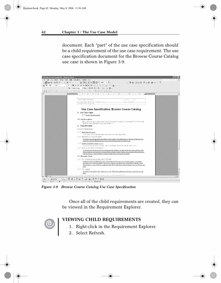
document. Each “part” of the use case specification should be a child requirement of the use case requirement. The use case specification document for the Browse Course Catalog use case is shown in Figure 3-9.
Once all of the child requirements are created, they can be viewed in the Requirement Explorer.
VIEWING CHILD REQUIREMENTS
1. Right-click in the Requirement Explorer.2. Select Refresh.
Figure 3-9 Browse Course Catalog Use Case Specification
Quatrani.book Page 42 Monday, May 8, 2006 11:56 AM
USE CASE DIAGRAMS 43
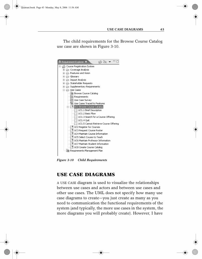
The child requirements for the Browse Course Catalog use case are shown in Figure 3-10.
USE CASE DIAGRAMS
A USE CASE diagram is used to visualize the relationships between use cases and actors and between use cases and other use cases. The UML does not specify how many use case diagrams to create—you just create as many as you need to communication the functional requirements of the system (and typically, the more use cases in the system, the more diagrams you will probably create). However, I have
Figure 3-10 Child Requirements
Quatrani.book Page 43 Monday, May 8, 2006 11:56 AM

44 Chapter 3 / The Use Case Model
found that no matter how many use cases you have, the fol-lowing use case diagrams are always created:
■ Main use case diagram showing the functional use case packages
■ A diagram showing the most important use cases (for smaller systems this diagram may contain all of the use cases; for larger systems this diagram contains the architecturally significant use cases)
■ A main diagram for each functional area showing the use cases in that functional area
If you used the use case model template, all of these dia-grams are created—all you need to do is populate them.
OPENING A USE CASE DIAGRAM
1. In the Model Explorer, double-click on the diagram.
You may feel the need to create additional diagrams. This is usually the case if you have a large system with many use cases. Some examples of additional diagrams are:
■ A diagram showing all of the use cases for a given actor
■ A diagram showing use cases that are executed in one sequence
■ Use cases that are being implemented for a par-ticular iteration
CREATING A USE CASE DIAGRAM
1. In the Model Explorer, right-click on the owning package.
Quatrani.book Page 44 Monday, May 8, 2006 11:56 AM
USE CASE DIAGRAMS 45
2. Select Add Diagram > Use Case.3. This will add a new diagram to the Model Explorer.
While the diagram is still selected, enter its name.
Actor–Use Case Relationships
Communication between an actor and a use case is shown with an association. This type of association is often referred to as a communicate association. There is only one communicate association between an actor and a use case no matter how many messages pass between the actor and the use case.
CREATING USE CASE–ACTOR RELATIONSHIPS
1. Double-click on the diagram containing the relation-ship to open it.
2. Drag the use case from the Model Explorer onto the diagram.
3. Select the actor(s) that interact with the use case (Note: to multi-select actors in the Model Explorer, depress the Shift key) and drag them onto the dia-gram.
4. Click the Association item in the Palette.5. Click on the actor in the diagram and drag the asso-
ciation to the use case.
The use case diagrams for the Course Registration Sys-tem are shown in Figures 3-11, 3-12, 3-13, and 3-14.
Quatrani.book Page 45 Monday, May 8, 2006 11:56 AM

46 Chapter 3 / The Use Case Model
Figure 3-11 Overview Diagram
Figure 3-12 All Use Cases
Quatrani.book Page 46 Monday, May 8, 2006 11:56 AM

Figure 3-13 Course Registration Use Cases
Figure 3-14 System Maintenance Use Cases
Quatrani.book Page 47 Monday, May 8, 2006 11:56 AM

48 Chapter 3 / The Use Case Model
Relationships Between Use Cases
There are two types of relationships that may exist between use cases: include and extend. Multiple use cases may share pieces of the same functionality. This functionality is placed in a separate use case rather than documenting it in every use case that needs it.
Include relationships are created between the new use case and any other use case that “uses” its functionality. For example, each use case in the ESU Course Registration System starts with the verification of the user. This func-tionality can be captured in a User Verification use case, which is then used by other use cases as needed. An include relationship is drawn as a dependency relationship that points from the base use case to the used use case.
An extend relationship is used to show
■ Optional behavior
■ Behavior that is run only under certain condi-tions, such as triggering an alarm
■ Several different flows that may be run based on actor selection
For example, if a current selection is not available during the Register for Courses use cases, the student may want to see what other courses are available. Thus, the Browse Course Catalog use case may be an extension of the Register for Courses use case. An extend relationship is drawn as a dependency relationship that points from the extension to the base use case.
The UML has a concept called a stereotype, which pro-vides the capability of extending the basic modeling ele-ments to create new elements. Thus, the concept of a stereotype allows the UML to have a minimal set of sym-bols that may be extended where needed to provide the
Quatrani.book Page 48 Monday, May 8, 2006 11:56 AM

USE CASE DIAGRAMS 49
communication artifacts that have meaning for the system under development. Stereotype names are included within guillemets (<< >>) and placed along the relationship line. Stereotypes are used to create the needed use case relation-ships. The stereotype <<communicate>> may be added to an association to show that the association is a communi-cate association. This is optional since an association is the only type of relationship allowed between an actor and a use case. Include and extend relationships must use stereo-types since they are both represented by a dependency relationship.
CREATING INCLUDE AND EXTEND RELATIONSHIPS
1. Drag the use cases in the relationship from the Model Explorer onto a diagram.
2. Select the Include or Extend icon in the Palette. (The last used icon will be visible in the Palette. If that is not the icon that you need, click the arrow next to it to make the other relationship icons visible.)
3. For an include relationship, click on the base use case and drag the dependency relationship to the included use case.
4. For an extend relationship, click on the use case with the extended functionality and drag the relationship to the base use case.
Use case relationships are shown in Figure 3-15.
Quatrani.book Page 49 Monday, May 8, 2006 11:56 AM

50 Chapter 3 / The Use Case Model
ACTIVITY DIAGRAMS
A.3.3
ACTIVITY DIAGRAMS MAY be created at this stage in the life cycle to show the flow of control and data flow within a use case. Activities are containing nodes that include actions and control flow and/or data flow between the actions. The diagrams show action sequence, control flows, and joins and decision points.
Actions
An action represents the performance of some behavior in the workflow. In UML, an action is shown as a round-cornered rectangle, as shown in Figure 3-16.
Actions can be determined by examining the use case specification and determining what behaviors are needed to
Figure 3-15 Use Case Relationships
Quatrani.book Page 50 Monday, May 8, 2006 11:56 AM

ACTIVITY DIAGRAMS 51
execute the steps of the use case. Many times, the titles cre-ated for a use case requirement will map to a behavior that a use case must execute
CREATING ACTIONS
1. Click to select the Action icon from the Palette.2. Click on the activity diagram window to place the
action.3. While the action is still selected, enter the name of
the action.
Control Flows
Once an action finishes, control is passed to the next action in the activity diagram. Control flows show the passing of control from one action to the next action in sequence. In UML, a control flow is represented as a directed arrow, as shown in Figure 3-17.
CREATING CONTROL FLOWS
1. Click to select the Control Flow icon from the Palette.2. Click on the originating action and drag the control
flow arrow to the successor action.
Figure 3-16 Action
Figure 3-17 Control Flow
Quatrani.book Page 51 Monday, May 8, 2006 11:56 AM
52 Chapter 3 / The Use Case Model
Decision Points
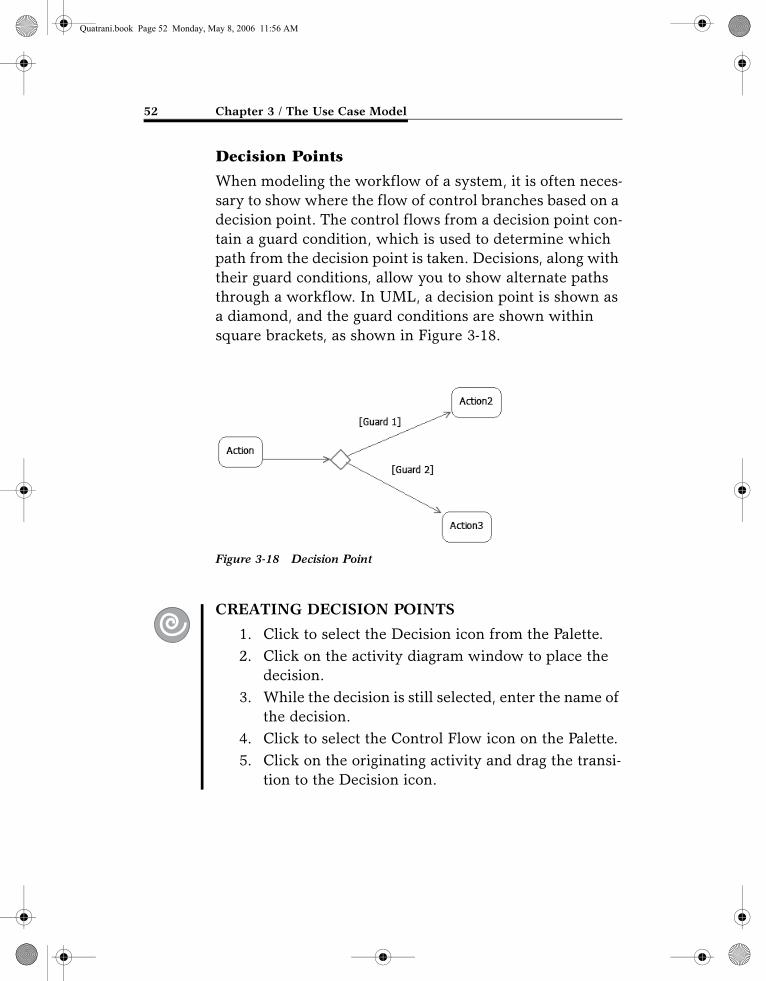
When modeling the workflow of a system, it is often neces-sary to show where the flow of control branches based on a decision point. The control flows from a decision point con-tain a guard condition, which is used to determine which path from the decision point is taken. Decisions, along with their guard conditions, allow you to show alternate paths through a workflow. In UML, a decision point is shown as a diamond, and the guard conditions are shown within square brackets, as shown in Figure 3-18.
CREATING DECISION POINTS
1. Click to select the Decision icon from the Palette.2. Click on the activity diagram window to place the
decision.3. While the decision is still selected, enter the name of
the decision.4. Click to select the Control Flow icon on the Palette.5. Click on the originating activity and drag the transi-
tion to the Decision icon.
Figure 3-18 Decision Point
Quatrani.book Page 52 Monday, May 8, 2006 11:56 AM

ACTIVITY DIAGRAMS 53
CREATING GUARD CONDITIONS
1. Click to select the control flow in the diagram.2. Select the Properties window.3. Enter the guard condition in the Body Text field.
Object Flows
There are many times that you want to show the flow of data along with the flow of control—that is, the data that flows between actions. An object flow denotes the flow from an action to data or from data to an action. In UML, data is typically shown as a rectangle, and like a control flow, a data flow is shown as a directed arrow. Flow of data is shown in Figure 3-19.
CREATING DATA STORES AND OBJECT FLOWS
1. Click to select the Object Node icon from the palette.2. Click on the activity diagram window and select
Create New Datastore Node.3. While the data store is still selected, enter the name
of the data store.4. Click to select the Object Flow icon on the Palette.5. Click on the originating action and drag the object
flow to the data store.
Figure 3-19 Data Flow
Quatrani.book Page 53 Monday, May 8, 2006 11:56 AM

54 Chapter 3 / The Use Case Model
Forking and Joining Flows of Control
In a workflow there are typically some actions that may be done in parallel. A fork node allows you to specify what activities may be done concurrently. A join node is used to show joins in the workflow—that is, what actions must complete before processing may continue. That said, a fork node has one incoming control flow and many outgoing control flows. A join node has many incoming control flows and one outgoing control flow. In UML, fork and join nodes are shown as line segments, as shown in Figure 3-20.
CREATING FORK NODES OR JOIN NODES
1. Click the arrow next to the Control Node icon in the Palette.
2. Select Fork or Join.
Figure 3-20 Fork and Join Nodes
Quatrani.book Page 54 Monday, May 8, 2006 11:56 AM

ACTIVITY DIAGRAMS 55
3. Click on the activity diagram window to place the fork node or join node.
4. Resize as needed.
Activity Partitions
Activity partitions may be used to group actions with some-thing in common in an activity diagram. This typically is done to show what person or organization is responsible for the activities contained in the partition. Activity partitions are shown in Figure 3-21.
CREATING ACTIVITY PARTITIONS
1. Right-click on the activity diagram in the Model Explorer.
2. Select Add UML > Partition. 3. While the partition is still selected in the Model
Explorer, add its name.
Figure 3-21 Activity Partitions
Quatrani.book Page 55 Monday, May 8, 2006 11:56 AM
56 Chapter 3 / The Use Case Model
Initial and Final Nodes
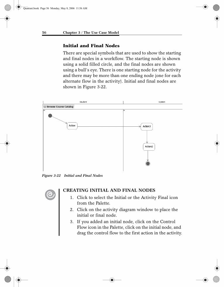
There are special symbols that are used to show the starting and final nodes in a workflow. The starting node is shown using a solid filled circle, and the final nodes are shown using a bull’s eye. There is one starting node for the activity and there may be more than one ending node (one for each alternate flow in the activity). Initial and final nodes are shown in Figure 3-22.
CREATING INITIAL AND FINAL NODES
1. Click to select the Initial or the Activity Final icon from the Palette.
2. Click on the activity diagram window to place the initial or final node.
3. If you added an initial node, click on the Control Flow icon in the Palette, click on the initial node, and drag the control flow to the first action in the activity.
Figure 3-22 Initial and Final Nodes
Quatrani.book Page 56 Monday, May 8, 2006 11:56 AM

SUMMARY 57
4. If you added a final node, click on the Control Flow icon in the Palette, click on the successor action, and drag the control flow to the final node.
The activity diagram for the Browse Course Catalog use case is shown in Figure 3-23.
SUMMARY
SYSTEM BEHAVIOR IS documented in a use case model that illustrates the system’s intended functions (use cases), its surroundings (actors), and the relationships between the use cases and actors (use case diagrams).
Figure 3-23 Browse Course Catalog Activity Diagram
Quatrani.book Page 57 Monday, May 8, 2006 11:56 AM

58 Chapter 3 / The Use Case Model
The most important role of a use case model is to com-municate the system’s functionality and behavior to the customer or end user.
Actors are not part of the system—they represent anyone or anything that must interact with the system under development.
Use cases represent the functionality provided by the system. They model a dialogue between an actor and the system.
Each use case contains a flow of events, which is a description of the events needed to accomplish the use case functionality. The flow of events is written in terms of what the system should do, not how the system does it.
A use case diagram is a graphical representation of some or all of the actors, use cases, and their interactions for a system.
There are two types of use case relationships: include and extend. An include relationship is drawn to show func-tionality that is shared by several use cases; an extend rela-tionship depicts optional behavior of a use case.
T.3.1
Activity diagrams represent the dynamics of the system. They are flow charts that are used to show the workflow of a system. At this point in the life cycle, activity diagrams may be created to represent the flow within a use case.
DEVELOPERWORKS LINKS
A.3.1 Gottesdeiner, E. Use case best practices. IBM developerWorks, November 2003: http://www-128.ibm.com/developerworks/rational/library/344.html
A.3.2 Pan-Wei Ng. Adopting use cases. developerWorks, November 2003: http://www-128.ibm.com/developerworks/rational/library/1809.html
Quatrani.book Page 58 Monday, May 8, 2006 11:56 AM

DEVELOPERWORKS LINKS 59
A.3.3 Ericcson, M. Activity diagrams: What they are and how to use them. developerWorks, April 2004: http://www128.ibm.com/developerworks/rational/library/2802.html
T.3.1 Two-part use case modeling Web-based course (fee-based): Principles of use case modeling with UML. developerWorks, January 2005. Part One begins at http://www-128.ibm.com/developerworks/rational/library/4177.html
Quatrani.book Page 59 Monday, May 8, 2006 11:56 AM