The U.S. Department of Energy’s Post- combustion Carbon ... - NETL - Jared Ciferno... · The U.S....
43
The U.S. Department of Energy’s Post- combustion Carbon Dioxide Capture R&D Program — Technology Update Jared Ciferno, Technology Manager Existing Plants Program
-
Upload
trinhkhanh -
Category
Documents
-
view
213 -
download
0
Transcript of The U.S. Department of Energy’s Post- combustion Carbon ... - NETL - Jared Ciferno... · The U.S....

The U.S. Department of Energy’s Post-combustion Carbon Dioxide Capture R&D Program — Technology Update
Jared Ciferno, Technology ManagerExisting Plants Program
2
Presentation Outline
• DOE/NETL CO2 Capture R&D Program
• PC Post-combustion CO2 Capture– Solvents, Sorbents, Membranes
• PC Oxycombustion CO2 Capture– Pulverized Coal– Chemical Looping
• Advanced CO2 Compression
• DOE National Carbon Capture Center

3
DOE/NETL CO2 Capture R&D
Existing PlantsPost-Combustion CO2
PC Oxycombustion
SequestrationPre-Combustion CO2
Gasification
Advanced Research
Office of Research& Development
Office of Systems, Analyses and Planning
Fuels
Demonstration Programs
FutureGen
Clean Coal PowerInitiative
NETL’s Carbon Capture
R&D
R&D Programs
Demonstration Programs
4
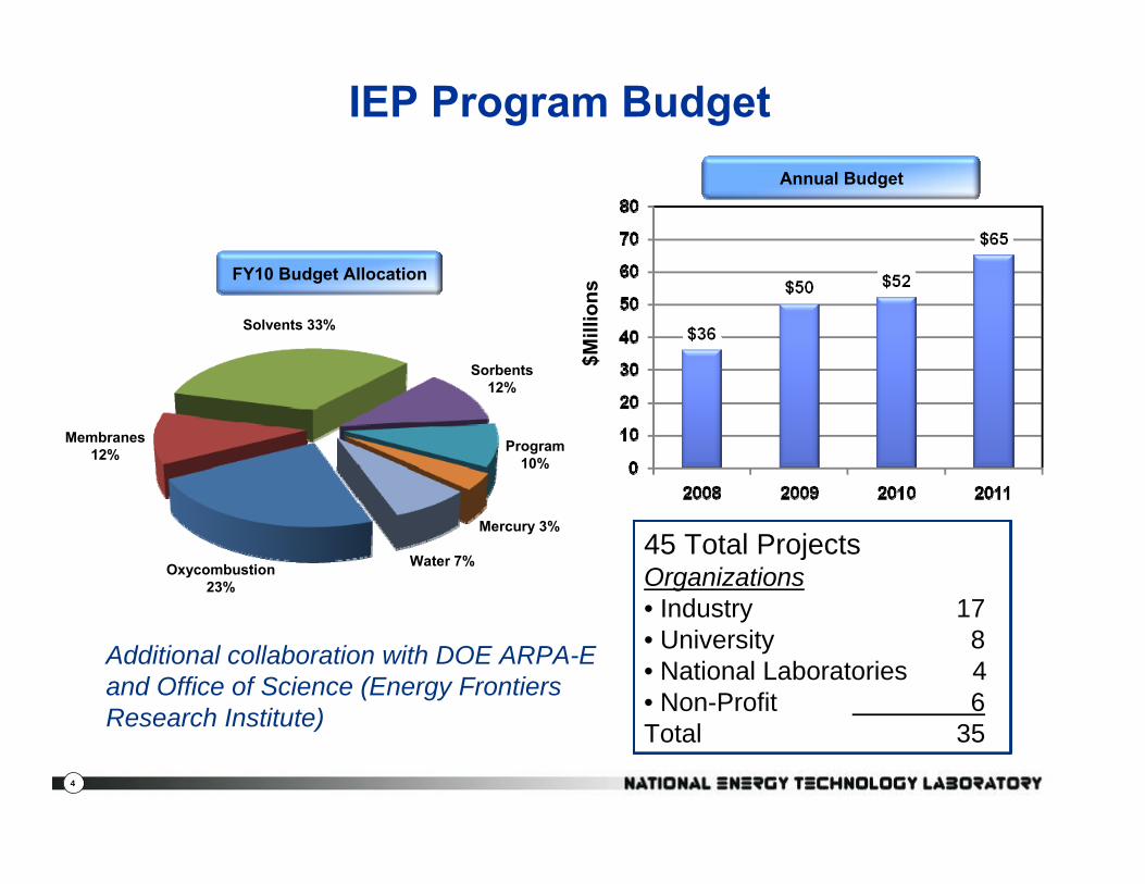
IEP Program Budget
Water 7%
Mercury 3%
Sorbents12%
Solvents 33%
Membranes12%
Oxycombustion23%
Program10%
FY10 Budget Allocation
45 Total ProjectsOrganizations• Industry 17• University 8• National Laboratories 4• Non-Profit 6Total 35
Annual Budget
$Mill
ions
Additional collaboration with DOE ARPA-E and Office of Science (Energy Frontiers Research Institute)

5
1. Scale-up• Current PC capture ~200 tons/day
• 550 MWe plant produces 13,000 tons/day
2. Energy Demand• 20% to 30% in power output
3. Current Cost (for a 550 Mwe plant)• Adds $1500 - $2000/kW capital
• Increase Cost of Electricity (COE) by 80%
4. Regulatory framework• Transport — pipeline network
• Storage
Deployment Barriers for CO2 Capture on New and Existing Coal Plants Today

6
Fossil Energy CO2 Capture Options
Source: Cost and Performance Baseline for Fossil Energy Power Plants study, Volume 1: Bituminous Coal and Natural Gas to Electricity; NETL, May 2007.
Pulverized Coal (PC)Post-combustion
PC Oxy-combustion
Gasification (IGCC)Pre-combustion

7
Fossil Energy CO2 Capture Solutions
Ready for Demonstration
1st Generation physical solvents (CCPI)1st Generation chemical solvents (CCPI)Adv. CO2compression(Ramgen)
Amine solventsPhysical solventsCryogenic oxygen
Chemical looping2nd Gen. OxyboilerBiological processesSolid Sorbents
Cos
t Red
uctio
n B
enef
it 2nd Gen. SolventsH2 and CO2MembranesOxygen Membranes
Post-combustion (existing, new PC)
Pre-combustion (IGCC)
Oxycombustion (new PC)
CO2 compression (all)
202020152010
OTM – O2 Transport Membrane (PC)

8
R&D Timeline to Commercial Demonstration
20102008 20162012 2020 2024
Pilot-Scale Field Testing0.5 — 5 MWe
Large-Scale Field Testing5 — 25 MWe
CommercialDemonstration
Laboratory-Bench Scale R&D
- DOE National CarbonCapture Center
- Utility sites
Core R&D Program Projects 2010 Funding Opportunity Announcement

9
Presentation Outline
• DOE/NETL CO2 Capture R&D Program
• PC Post-combustion CO2 Capture– Solvents, Sorbents, Membranes
• PC Oxycombustion CO2 Capture– Pulverized Coal– Chemical Looping
• Advanced CO2 Compression
• DOE National Carbon Capture Center
Post-combustion

10
PC Boiler(With SCR)
Sulfur Removal
ParticulateRemoval
Ash
Coal
STEAMCYCLE
CO2 CaptureProcess*
ID Fan
Air
Power
CO2Comp.
Flue Gas
CO2 To Storage2,215 psia
Low Pressure Steam
Optional Bypass(<90% Capture)
Post-combustion CO2 CaptureAmine-based scrubbing
Reference: Pulverized Coal Oxycombustion Power Plants—Volume 1 Bituminous Coal to Electricity, U.S. Department of Energy/National Energy Technology Laboratory, Revision 2 Final Report, August 2008
Two-step separation process requiring 5 energy inputs:
Energy = Q (sensible) + Q (reaction) + Q (stripping) + W (Process) + W (Compression)
ALL must be reduced in order to significantly reduce Capture COE impact!
0
10
20
30
40
50
60
70
80
90
Perc
ent I
ncre
ase
in C
OE
Trans., Stor., & Monit.Compression CapitalCapture CapitalCapture OperatingCapture SteamCapture Aux. PowerCompression power
13%
11%
28%
7%
20%
5%2%
Parasitic PowerCOE by 52%
Operating CostCOE by 7%
Capital CostCOE by 27%

11
Advanced CO2 Solvents
Solvent Technologies• Ionic liquids• Potassium carbonate/enzymes• Phase change solvents• Novel high capacity oligomers• Bicarbonates/additives• Molecular simulations• Enzymes
Today: Laboratory-scale2011: 1 MWe Pilot Scale2015: 5 – 25 MWe Pilot Scale2018: Demonstration Scale
Partners: 1. University of Notre Dame2. Georgia Tech.3. Illinois St. Geological Survey 4. 3H 5. GE Research Corporation6. Lawrence Berkeley Nat. Lab. 7. Siemens Energy8. URS Corporation9. Akermin10. Ion Engineering
Solvent R&D Focus• High CO2 working capacity
( Qsensible, Wprocess)• Low regeneration energy
( Qsensible, Qreaction , Qstripping )• Fast kinetics ( Equipment Size)• Thermally and chemically stable• Non-corrosive, environmentally safe
Development Timeline

12
Solvents: Ionic Liquids University of Notre Dame
Maturity: Laboratory Scale• On 4th year of R&D with Univ. of Notre Dame
– 19x increase in CO2 solubility for physical Ils, 40x increase in CO2 solubility for “functionalized” (amine groups) Ils.
Organic salts with a melting point below 100oC. Choice of anion and cation components determines the physiochemical properties
Advantages:• Interaction mechanisms: physical, electrostatic, charge-transfer, chemical ( Qreaction)• Huge diversity of chemical compounds 105 ( All Energy Inputs)• Computational methods to ‘tune’ molecules for flue gas or syngas applications• Integrate molecular design with process design ( All Energy Inputs)• Low vapor pressure, thermally stable >200oC ( Qstripping, Wcompression)• “Functionalized” chemistry to CO2 capacity and selectivity ( Qsensible, Wprocess)• Supported (membrane) and non-supported process options Challenges:• Current molecules showing low CO2 working capacity• High viscosity (100 to 1,110 centipoise)• Water absorption (flue gas is saturated), sulfur absorption• High chemical cost, unique chemistry — chemical syntheses• 105 varieties — computational modeling to design and down-select
1-n-hexyl-3,5-dimethylpyridinum
bis(trifluoromethane-sulfonyl)amide
13
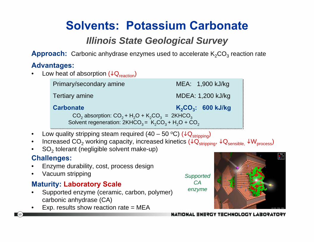
Solvents: Potassium Carbonate Illinois State Geological Survey
Primary/secondary amine MEA: 1,900 kJ/kg
Tertiary amine MDEA: 1,200 kJ/kg
Carbonate K2CO3: 600 kJ/kgCO2 absorption: CO2 + H2O + K2CO3 = 2KHCO3
Solvent regeneration: 2KHCO3 = K2CO3 + H2O + CO2
Primary/secondary amine MEA: 1,900 kJ/kg
Tertiary amine MDEA: 1,200 kJ/kg
Carbonate K2CO3: 600 kJ/kgCO2 absorption: CO2 + H2O + K2CO3 = 2KHCO3
Solvent regeneration: 2KHCO3 = K2CO3 + H2O + CO2
Advantages:• Low heat of absorption ( Qreaction)
• Low quality stripping steam required (40 – 50 oC) ( Qstripping)• Increased CO2 working capacity, increased kinetics ( Qstripping, Qsensible, Wprocess)• SO2 tolerant (negligible solvent make-up)Challenges:• Enzyme durability, cost, process design• Vacuum stripping
Maturity: Laboratory Scale• Supported enzyme (ceramic, carbon, polymer)
carbonic anhydrase (CA)• Exp. results show reaction rate = MEA
Approach: Carbonic anhydrase enzymes used to accelerate K2CO3 reaction rate
Supported CA
enzyme

14
CO2 Capture by Self-Concentrating Amine Absorbent
3H Company, Inc.Approach:• Develop solvent/absorbent mixtures that can separate into two
phases upon CO2 absorption• Only regenerate the CO2 rich phase• Reduced solvent recirculation• High solvent capacity• Lower overall regeneration energy• Lower auxiliary power • Reduced corrosion• Reduced equipment size• Demonstrated mixtures include
non-aqueous solventmixed with conventionalamines as absorbents
Flue Gas
Purified Flue GasCO2
Absorber Regenerator
Settler
CO2‐lean Phase
CO2‐rich Phase
Maturity: Laboratory Scale
15
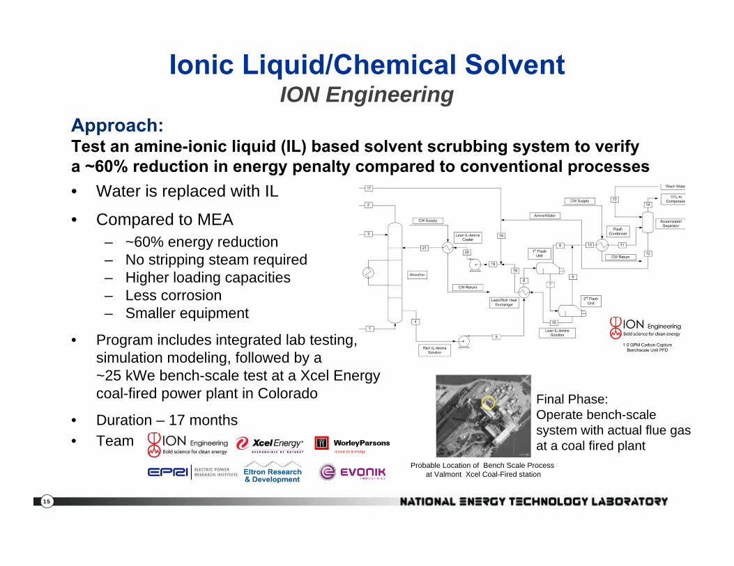
Approach:Test an amine-ionic liquid (IL) based solvent scrubbing system to verifya ~60% reduction in energy penalty compared to conventional processes• Water is replaced with IL
• Compared to MEA – ~60% energy reduction – No stripping steam required– Higher loading capacities– Less corrosion– Smaller equipment
• Program includes integrated lab testing, simulation modeling, followed by a~25 kWe bench-scale test at a Xcel Energycoal-fired power plant in Colorado
• Duration – 17 months• Team
Ionic Liquid/Chemical Solvent ION Engineering
Final Phase: Operate bench-scale system with actual flue gas at a coal fired plant
Probable Location of Bench Scale Process at Valmont Xcel Coal-Fired station

16
Siemens POSTCAP Amino AcidCO2 Capture Technology
Siemens Energy, Inc.Approach: • 2.5 MWe Amino Acid Solvent slipstream at TECO’s Big Bend
Station – Amino acid salt (AAS) designed to operate in a conventional
absorption/scrubbing system, however lab test showed:• Less corrosion than MEA• Lower volatility than MEA• Lower regeneration than MEA (2.64 GJ/tonne CO2 vs 4.25)• Capacity similar to hindered amine• Moderately better than MHI’s hindered amine
– Systems analysis shows 44% increase in COE– 5000 hours of bench-scale operation
Maturity: 2.5 Mwe Slip-stream
17
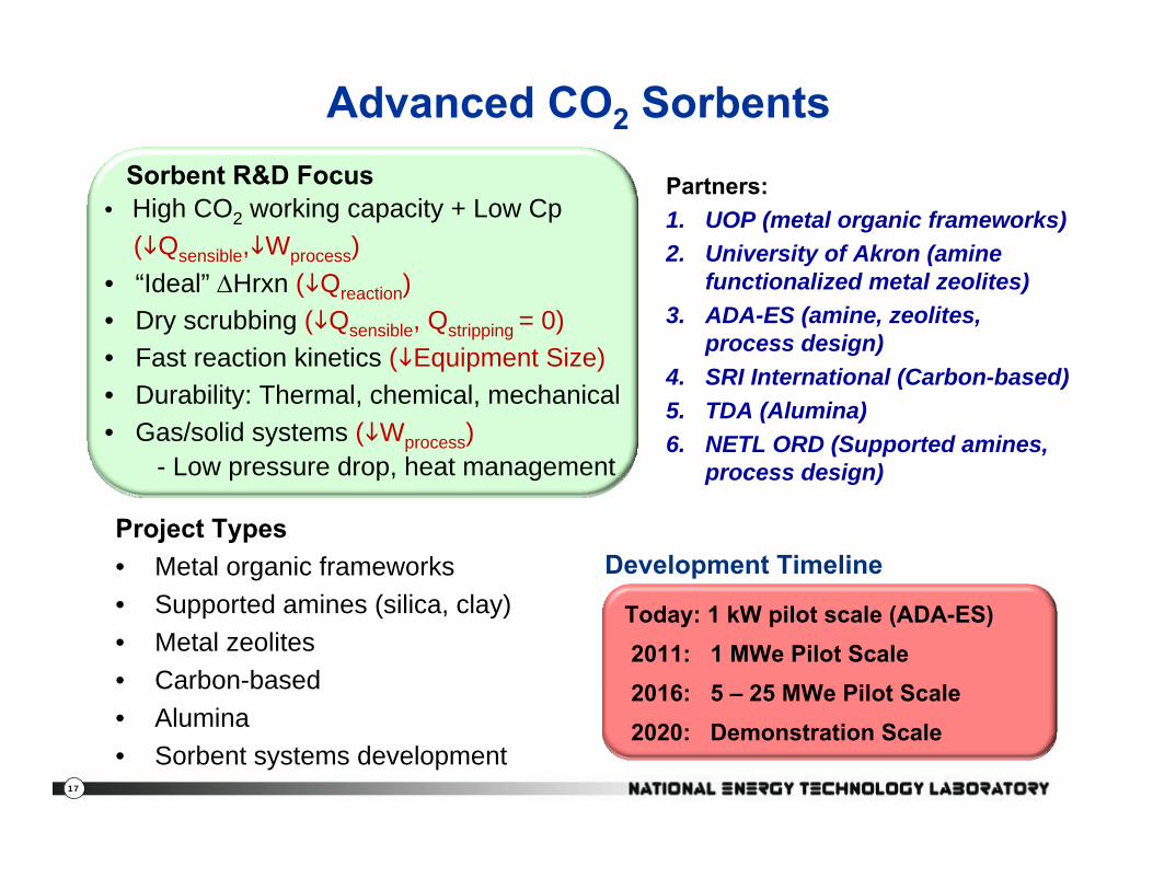
Advanced CO2 Sorbents
Partners: 1. UOP (metal organic frameworks)2. University of Akron (amine
functionalized metal zeolites) 3. ADA-ES (amine, zeolites,
process design) 4. SRI International (Carbon-based)5. TDA (Alumina)6. NETL ORD (Supported amines,
process design)
Project Types• Metal organic frameworks• Supported amines (silica, clay)• Metal zeolites• Carbon-based• Alumina• Sorbent systems development
Sorbent R&D Focus • High CO2 working capacity + Low Cp
( Qsensible, Wprocess)• “Ideal” ΔHrxn ( Qreaction)• Dry scrubbing ( Qsensible, Qstripping = 0)• Fast reaction kinetics ( Equipment Size)• Durability: Thermal, chemical, mechanical• Gas/solid systems ( Wprocess)
- Low pressure drop, heat management
Today: 1 kW pilot scale (ADA-ES)2011: 1 MWe Pilot Scale2016: 5 – 25 MWe Pilot Scale2020: Demonstration Scale
Development Timeline

18
Solid Sorbents: Metal Organic FrameworkUOP
Challenges:• Flue gas contaminants (SOx, NOx)• Moisture • System design (pressure drop, large vacuum pumps at 0.01 – 0.05 atm.)• Material and production cost
MOF: Metal “hubs” attached by organic linkers designed to create high surface area, crystalline, microporous and thermally-stable materials.
=
=
Advantages:• High CO2 working capacity (10 - 20%)• Thermally stable to 250 - 400oC• Hydrothermal stability 100 - 200oC

19
Solid Sorbents: Metal Organic FrameworkUOP
Current State: 4 years at laboratory scale• 50+ MOFs for CO2 adsorption prepared down selected to 10 best• Surface area 500 – 2000 m2/g• Independent systems analysis (PSA design) showed COE penalty
decrease from 85% to 55%a
0
0.05
0.1
0.15
0.2
0.25
0.3
0.35
0 0.1 0.2 0.3 0.4 0.5pressure, atm
g C
O2/
g a
dsor
bent
Mg/DOBDC
Ni/DOBDC
MIL-101
ZIF-100
ZIF-100 data from Wang, et al, Nature 2008, 453, 207
= DOBDC linker
OHO
HO O
OH
HO
M/DOBDC MOF
0
0.05
0.1
0.15
0.2
0.25
0.3
0.35
0 0.1 0.2 0.3 0.4 0.5pressure, atm
g C
O2/
g a
dsor
bent
Mg/DOBDC
Ni/DOBDC
MIL-101
ZIF-100
ZIF-100 data from Wang, et al, Nature 2008, 453, 207
= DOBDC linker
OHO
HO O
OH
HO
OHO
HO O
OH
HO
OHO
HO O
OH
HO
M/DOBDC MOF
“Top Ten” MOFs(January 2010)
aCurrent & Future Pulverized Coal Power Generation Technologies: A Pathway Study Focused on Post-combustion Carbon Capture, Noblis for DOE/NETL, May 6, 2010.

20
Reactors for CO2 Dry SorbentsNETL Office of Research and Development
Analysis of five reactor systems to use sorbents:– Structured Bed Concept
• Fixed bed sorber, with internal heat removal• Internal heating of same bed for regeneration
– Moving Bed Concept• Moving bed sorber, with internal heat removal• Moving bed regenerator, with internal heating
– Fluidized Bed Concept • Fluid bed sorber, with internal heat removal• Moving bed regenerator, with internal heating
– Fixed Bed Adsorber Concept• Fixed bed sorber, adiabatic, multi-stage with
interstage heat removal• Heating of same bed for regeneration with hot fluid
stream– Transport Reactor
• Circulating fluid bed sorber• Circulating fluid or moving bed regenerator
FUNCTIONS AND FLOWS OF INFORMATION AND MATERIALS
Process engineering,
design, economics
R&D lab-scale unit design &
construct
Lab-scale operation
Sorbent synthesis
Isotherm development
High-surface area formation
Other physical properties
9
10
11
12
1
2
3 5
4
6 7
8
Needed
ORD workOn reactors

21
Solid Sorbents: Pilot-scale development ADA-ES, Inc.Approach:
• Evaluate performance of 100+ CO2 capture sorbents at bench-scle using simulated flue gas
Success Criteria:• Working capacity, Reaction Energy,Theoretical Regeneration Energy, Consistent
performance, Reaction Kinetics, Durability, Cost
• 1 kW pilot-scale slip-stream tests beginning Jan 2010at 3 field-sites:
Luminant Martin Lake: Lignite (Completed)Xcel Energy Sherco: PRBNCCC Alabama Power Gaston: Bituminous
60 ft

22
Advanced Flue Gas CO2 Membranes
Today: 1 Ton/day slipstream (MTR)2011: 1 MWe Pilot Scale2015: 5 – 25 MWe Pilot Scale2018: Demonstration Scale
Development Timeline
Membrane Advantages• Simple operation; no chemical
reactions, no moving parts• Tolerance to acid gases & O2
• Compact, modular small footprint• Builds on existing technology at
similar scale (NG purification)
Membrane Technology Research, Research Triangle Institute, Air Liquide, Gas Technology Institute
Membrane Approaches• Mixed matrix/ionic liquid• Spiral wound• Hollow fiber• Membrane/solvent hybrid• Cryogenic separation
Energy = Q (sensible) + Q (reaction) + Q (stripping) + W (Process) + W (Compression)
0 0 0
Challenges• Cost reduction and scale-up• PM contamination• Power plant integration (recycle)• PCO2 driving force Increased
power consumption
23
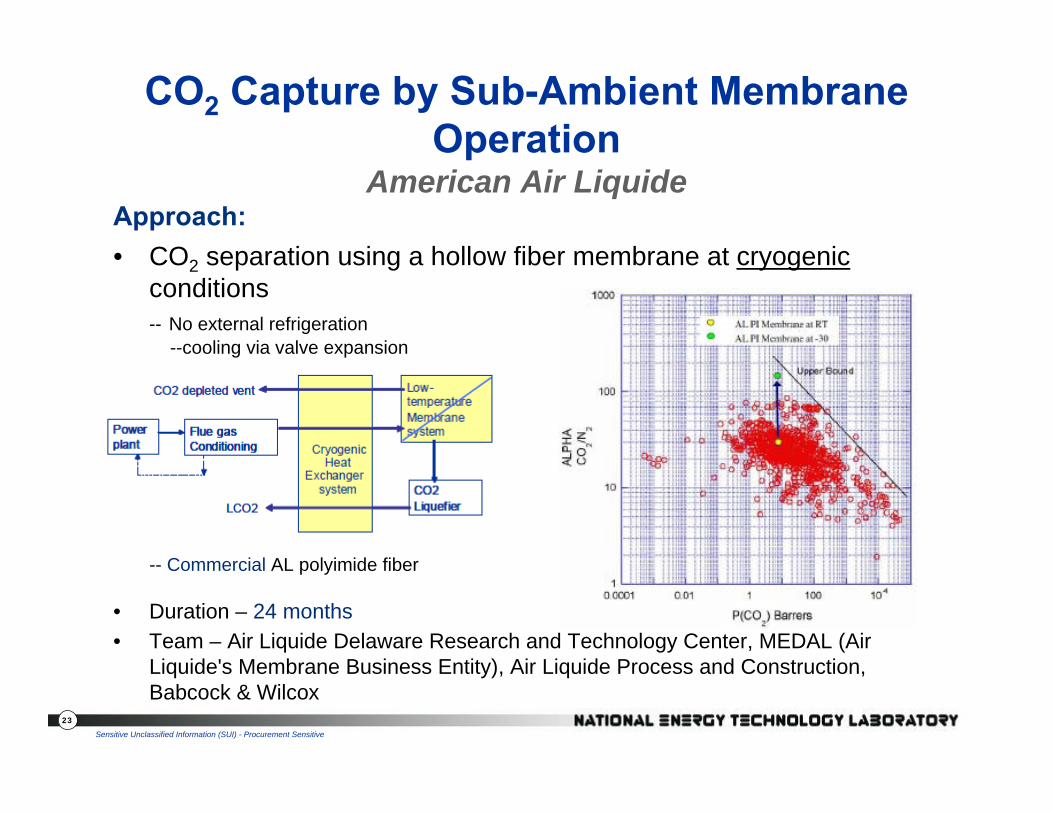
CO2 Capture by Sub-Ambient Membrane Operation
American Air LiquideApproach:• CO2 separation using a hollow fiber membrane at cryogenic
conditions-- No external refrigeration
--cooling via valve expansion
-- Commercial AL polyimide fiber
• Duration – 24 months• Team – Air Liquide Delaware Research and Technology Center, MEDAL (Air
Liquide's Membrane Business Entity), Air Liquide Process and Construction, Babcock & Wilcox
Sensitive Unclassified Information (SUI) - Procurement Sensitive

24
Hybrid Membrane/Absorption Process (Membrane Contactor)
Gas Technology Institute
Approach:• Hybrid membrane/solvent absorption process.
– PEEK hollow fiber membrane
– Increases interfacial gas/liquid contact area 10x over conventional packed or tray columns — increases mass transfer
– Selectivity controlled by solvent chemical affinity– Low steam regeneration energy– CO2 generated at pressure– Planned slipstream test at
Midwest Generation’s Joliet PowerStation (Size: 25 kWe)
• Duration – 36 months• Team – PoroGen Corp., Aker Process Systems, Midwest Generation
PEEK—Polymer ether ether ketone

25
Skid footprint is 24’ x 7’250,000 scfd flue gas slipstream
Post-Combustion CO2 Membrane Progress
10
20
30
40
50
60
100 1,000 10,000
CO2/N2selectivity
CO2 permeance (gpu)
PolarisTM
Target area identified from
design calculations
Commercial CA membranes
2008
Laboratory Results
2009
Process Design
10
15
20
25
30
35
40
0 20 40 60 80 100 120
Cost of capture
($/ton CO2)
Membrane CO2/N2 selectivity
1,000 gpu
1,500 gpu
3,000 gpu
90% CO2 recovery
PolarisTM 1
PolarisTM 3
CO2Permeance
Is it competitive?
aCurrent & Future Pulverized Coal Power Generation Technologies: A Pathway Study Focused on Post-combustion Carbon Capture, Noblis for DOE/NETL, May 6, 2010.
2010
Design and Scale-up

26
Membrane CO2 Capture Slipstream Membrane Technology and Research, Inc.
Approach: • 1 MW membrane pilot-scale at APS’ Cholla Power Plant
– PolarisTM polymer-based membrane designed for flue gas applications, developed with DOE/NETL support, have met membrane performance targets
– Currently carrying out a 0.05 Mwe (1 TPD) slip-stream plant at Cholla (XXX inch diameter modules)– The 1 Mwe (20 ton/day) test will be 12 inches in diameter
• Project Duration – 36 months• Team – Arizona Public Services, B&W,
Southern Company/NCCC, EPRI
10
20
30
40
50
60
100 1,000 10,000
CO2/N2selectivity
CO2 permeance (gpu)
PolarisTM
Target area identified from
design calculations
Commercial CA membranes
27
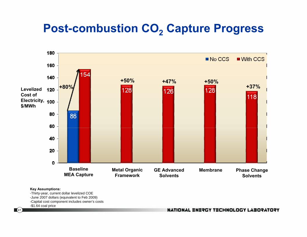
Post-combustion CO2 Capture Progress
Levelized Cost of Electricity, $/MWh
BaselineMEA Capture
Metal OrganicFramework
GE AdvancedSolvents
Phase ChangeSolvents
+80%+50% +47%
+37%
Key Assumptions:-Thirty-year, current dollar levelized COE-June 2007 dollars (equivalent to Feb 2009)-Capital cost component includes owner’s costs-$1.64 coal price
Membrane
+50%
28
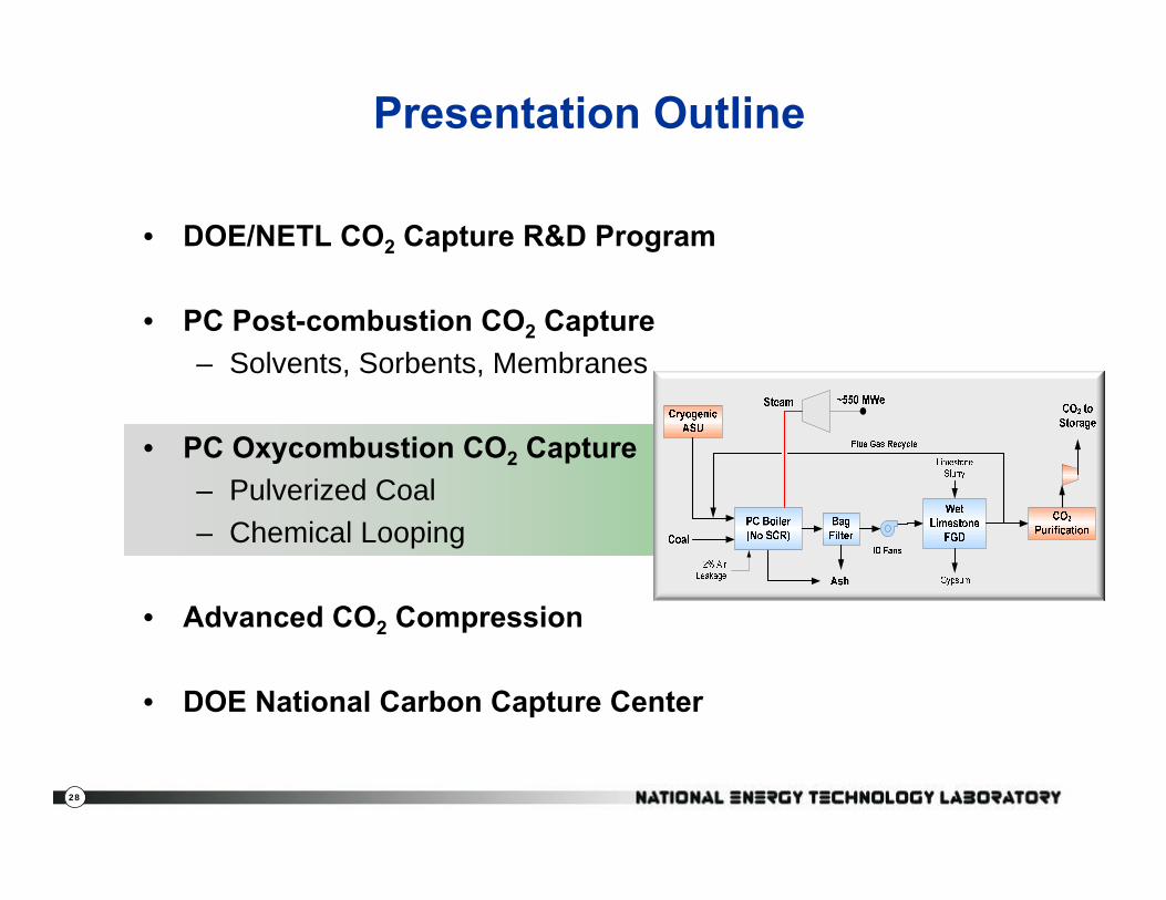
Presentation Outline
• DOE/NETL CO2 Capture R&D Program
• PC Post-combustion CO2 Capture– Solvents, Sorbents, Membranes
• PC Oxycombustion CO2 Capture– Pulverized Coal– Chemical Looping
• Advanced CO2 Compression
• DOE National Carbon Capture Center

29
Pulverized Coal Oxy-combustion
Coal + O2 CO2 + H2OCoal + O2 CO2 + H2O
Reference: Pulverized Coal Oxycombustion Power Plants—Volume 1 Bituminous Coal to Electricity, U.S. Department of Energy/National Energy Technology Laboratory, Revision 2 Final Report, August 2008
PC Oxy-combustion Advantages:• Plant vs. unit operation—multiple cost reduction
opportunities• Applicable to new and existing PC power plants• Current designs lower cost than amine wet scrubbing • Co-sequestration options
30
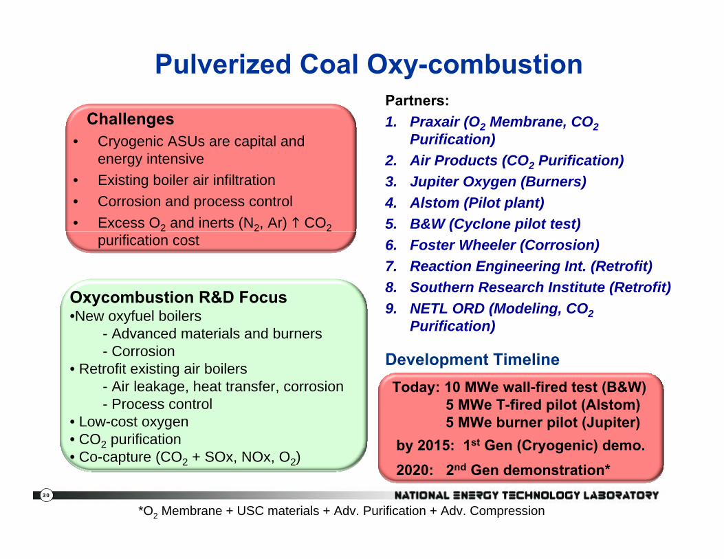
Pulverized Coal Oxy-combustionPartners: 1. Praxair (O2 Membrane, CO2
Purification)2. Air Products (CO2 Purification)3. Jupiter Oxygen (Burners) 4. Alstom (Pilot plant)5. B&W (Cyclone pilot test)6. Foster Wheeler (Corrosion)7. Reaction Engineering Int. (Retrofit)8. Southern Research Institute (Retrofit)9. NETL ORD (Modeling, CO2
Purification)
Challenges• Cryogenic ASUs are capital and
energy intensive• Existing boiler air infiltration• Corrosion and process control• Excess O2 and inerts (N2, Ar) CO2
purification cost
Today: 10 MWe wall-fired test (B&W)5 MWe T-fired pilot (Alstom)5 MWe burner pilot (Jupiter)
by 2015: 1st Gen (Cryogenic) demo. 2020: 2nd Gen demonstration*
Development Timeline
Oxycombustion R&D Focus •New oxyfuel boilers
- Advanced materials and burners- Corrosion
• Retrofit existing air boilers- Air leakage, heat transfer, corrosion - Process control
• Low-cost oxygen • CO2 purification • Co-capture (CO2 + SOx, NOx, O2)
*O2 Membrane + USC materials + Adv. Purification + Adv. Compression
31
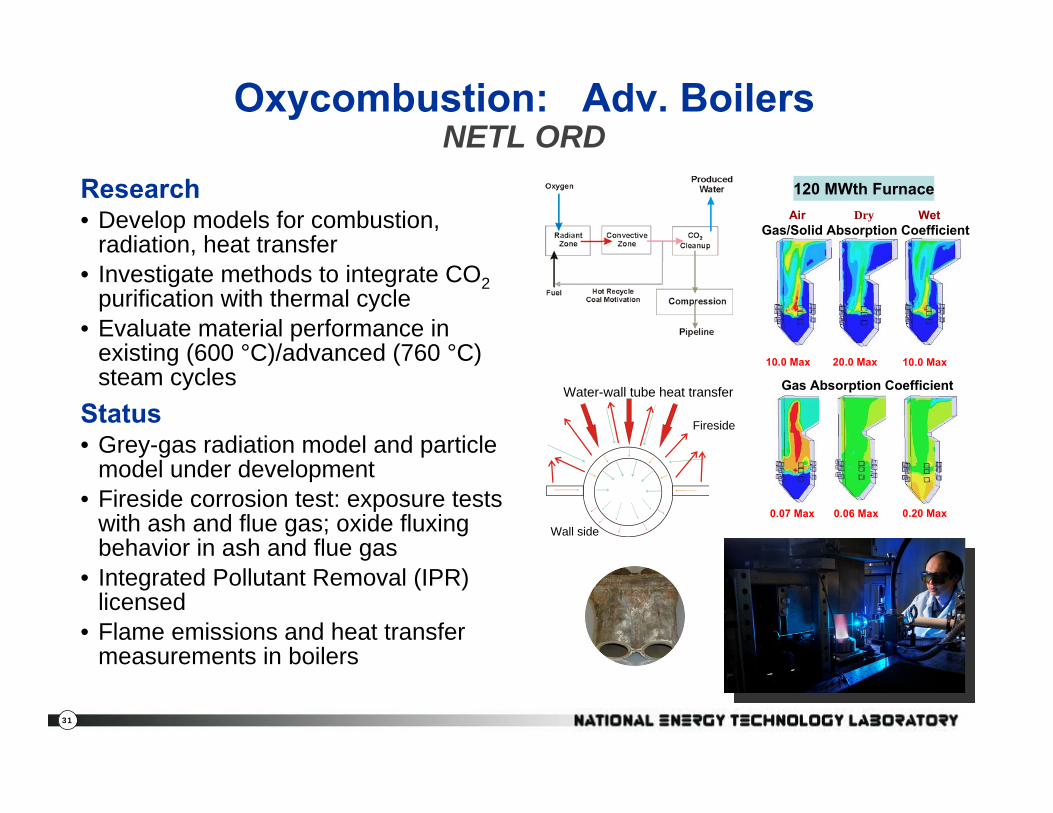
Air Dry Wet
Gas Absorption Coefficient
0.07 Max 0.06 Max 0.20 Max
120 MWth Furnace
10.0 Max 20.0 Max 10.0 Max
Gas/Solid Absorption Coefficient
Oxycombustion: Adv. BoilersNETL ORD
Research• Develop models for combustion,
radiation, heat transfer• Investigate methods to integrate CO2
purification with thermal cycle• Evaluate material performance in
existing (600 °C)/advanced (760 °C) steam cycles
Status• Grey-gas radiation model and particle
model under development• Fireside corrosion test: exposure tests
with ash and flue gas; oxide fluxing behavior in ash and flue gas
• Integrated Pollutant Removal (IPR) licensed
• Flame emissions and heat transfer measurements in boilers
Fireside
Wall side
Water-wall tube heat transfer

32
PC Oxycombustion Progress
Alstom Power
Flue GasAir Products
CO2 Purification Slip-Stream Test:• 2-stage compression/purification • Removes SOx, NOx, O2, & Inerts

33
Oxycombustion: Chemical Looping
Key Challenges• Solids transport• Heat Integration
Key Partners (2 projects): Alstom Power (Limestone Based), Ohio State (Metal Oxide)
Status2010 Alstom Pilot test (1 MWe)
1000 lb/hr coal flow1st Integrated operation1st Autothermal Operation
Red1700F
Ox2000F
CaS
Air
Fuel CO2 + H2O
CaSO4
MBHX N2 + O2
Steam
Fuel Reactor (Reducer)CaSO4 + 2C + Heat 2CO2 + CaSCaSO4 + 4H2 + Heat 4H2O + CaS
Air Reactor (Oxidizer)CaS + 2O2 CaSO4 + Heat
Oxy-Firing without Oxygen Plant
Solid Oxygen Carrier circulates between Oxidizer and Reducer
Oxygen Carrier: Carries Oxygen, Heat and Fuel Energy
Carrier picks up O2 in the Oxidizer, leaves N2 behind
Carrier Burns the Fuel in the Reducer
Heat produces Steam for Power

34
76
60
47 3025
0102030405060708090
A B C D E
`
Perc
ent I
ncre
ase
in C
OE
ADVANCEDO2 MembraneSupercritical ADVANCED
Adv. BoilerUltra-SupercriticalCo-Sequestration
O2 Membrane
ADVANCEDChemical LoopingUltra-Supercritical
Adv. BoilerCo-Sequestration
CURRENT STATESupercritical
Cryogenic ASU
Basis: 550 MW Net Output≥90 % CO2 Capture
CURRENT STATEAmine Scrubbing
Reference: Advancing Oxycombustion Technology for Bituminous Coal Power Plants: An R&D Guide, NETL 2010
?
Time to Commercialization
Pathway to Meeting NETL Goals

35
Presentation Outline
• DOE/NETL CO2 Capture R&D Program
• PC Post-combustion CO2 Capture– Solvents, Sorbents, Membranes
• PC Oxycombustion CO2 Capture– Pulverized Coal– Chemical Looping
• Advanced CO2 Compression
• DOE National Carbon Capture Center

36
Advanced CO2 Compression
R&D FocusReduce capital costsIncrease efficiencyIntegration with CO2 capture processModelingHeat recoveryReduced footprint
Projects:• Ramgen & Dresser Rand Shockwave Compression
• $20 MM DOE funded via ARRA (stimulus)• 13,000 hp demonstration test in 2011 – 2013
• Novel CO2 compression processes — Southwest Research Institute
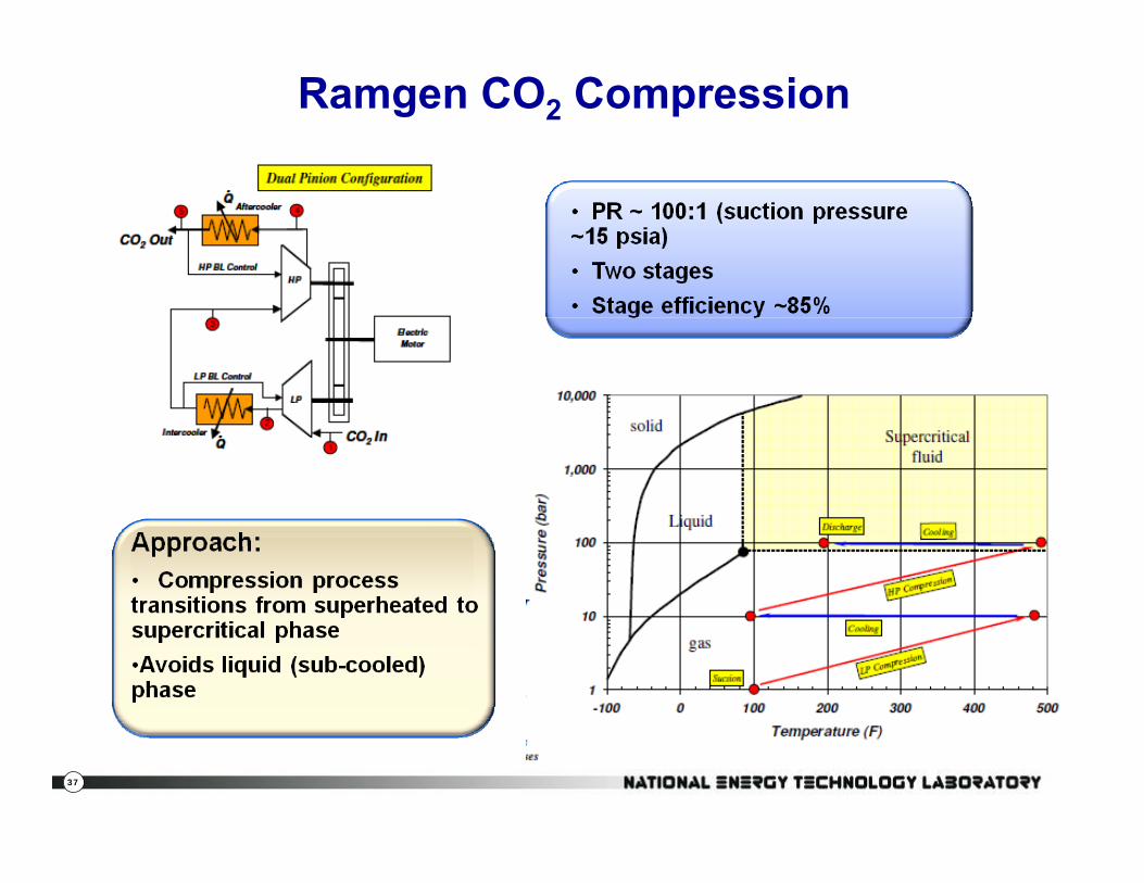
37
Ramgen CO2 Compression

38
Ramgen CO2 Compression
Courtesy: Ramgen
39
Presentation Outline
• DOE/NETL CO2 Capture R&D Program
• PC Post-combustion CO2 Capture– Solvents, Sorbents, Membranes
• PC Oxycombustion CO2 Capture– Pulverized Coal– Chemical Looping
• Advanced CO2 Compression
• DOE National Carbon Capture Center

40
National Carbon Capture Center (NCCC) at Power Systems Development Facility (PSDF)
Wilsonville, AL
NCCC Mission: Develop technologies that will lead to the commercialization of cost-effective, advanced coal fueled power plants with CO2 capture• 6 Mwe Transport Gasifier• 3 Mwe Post-Combustion Slipstream• Southern Company
– Peabody Energy– American Electric Power– Luminant– Arch Coal– RioTinto– Electric Power Research Institute

41
FGD
Stack
ID Fan
Plant Gaston
880 MWe12,000 tpd CO2
880 MWe12,000 tpd CO2
Pilot Solvent Test Unit #1
Pilot Test Unit #2
Pilot Test Unit #3
Bench Scale Test Units
Post-Combustion Capture Slip-StreamsAvailable for Technology Developers
3 MWe60 tpd CO2
3 MWe60 tpd CO2
0.5 MWe10 tpd CO2
0.5 MWe10 tpd CO2
1 MWe20 tpd CO2
1 MWe20 tpd CO2
< 0.1 MWe< 1 tpd CO2
< 0.1 MWe< 1 tpd CO2

42
http://www.netl.doe.gov/publications/index.html
Annual NETL CO2 Capture Technology R&D Meeting
Pre-, Post-, Oxycombustion CO2 Capture Technologies
Meeting will include ARPA-E CO2 Projects
Sheraton Station Square HotelPittsburgh, PA
September 13-17, 2010

43
•NETL website:−www.netl.doe.gov
• Annual CO2 Capture Meeting
Jared P. CifernoTechnology Manager, Innovation for Existing PlantsNational Energy Technology LaboratoryU. S. Department of Energy(Tel) 412 [email protected]
•Office of Fossil Energy website:−ww.fe.doe.gov
For More Information About the NETL Existing Plants Program
Reference Shelf