The Two-stage Push Belt CVT - Rienks Mechatronicsrienksmechatronics.com/PDF/VDTpaper IIR...
16
The Two-stage Push Belt CVT An Innovative Concept for High Power RWD and AWD Applications Ir. F. van der Sluis, H. Lamers, Ing. E. Hendriks Van Doorne’s Transmissie b.v., BOSCH Group, Tilburg Summary The Continuously Variable Transmission (CVT) is especially well known in front wheel driven vehicles. This paper discusses a solution for rear wheel driven vehicles. A prototype has been built to show that also for luxury and sports utility (SUV) class vehicles a push belt CVT option with torque levels up to 580 Nm is within reach. 1. Introduction Belt type CVT’s are explicitly suitable for front wheel drive (FWD) vehicles over conventional automatic transmissions. Therefore they can be found in these types of vehicles, mainly in the mid-upper car segment and pre-dominantly in the Japanese market. The rapidly growing market requires 1.2 million push belt CVT’s for 2002 that are used in about 30 different vehicle models. Though still at a starting phase, also the USA market reveals a promising future with the introduction in 2002 of two vehicles with push belt CVT, the Nissan Murano and the Saturn Vue. Both vehicles, typical for the USA market, are deliverable as FWD and all wheel drive (AWD). Also in Europe, where a new CVT production facility has been built, prospects look good. To extend the application range of its push belt, Van Doorne’s Transmissie is examining more severe requirements regarding transmittable power, torque, centre distance, ratio coverage and durability. To meet those requirements, the power density of belt and pulley needs to be increased [1]. First priority is the extension of power density for current belt interfaces, effectively increasing the range of existing CVT designs. The current push belt status is nicely shown by the introduction of the Nissan Murano with push belt CVT that has a ratio coverage of 5.4 and can cope with a 3.5 ltr V6 180 kW/350 Nm engine with torque convertor, applying drive side torque levels on the belt that lie above 500 Nm [2].
Transcript of The Two-stage Push Belt CVT - Rienks Mechatronicsrienksmechatronics.com/PDF/VDTpaper IIR...

The Two-stage Push Belt CVT
An Innovative Concept for High Power RWD and AWD Applications
Ir. F. van der Sluis, H. Lamers, Ing. E. Hendriks
Van Doorne’s Transmissie b.v., BOSCH Group, Tilburg
Summary
The Continuously Variable Transmission (CVT) is especially well known in front wheel driven vehicles.
This paper discusses a solution for rear wheel driven vehicles. A prototype has been built to show that
also for luxury and sports utility (SUV) class vehicles a push belt CVT option with torque levels up to 580
Nm is within reach.
1. Introduction
Belt type CVT’s are explicitly suitable for front wheel drive (FWD) vehicles over conventional
automatic transmissions. Therefore they can be found in these types of vehicles, mainly in the
mid-upper car segment and pre-dominantly in the Japanese market. The rapidly growing market
requires 1.2 million push belt CVT’s for 2002 that are used in about 30 different vehicle models.
Though still at a starting phase, also the USA market reveals a promising future with the
introduction in 2002 of two vehicles with push belt CVT, the Nissan Murano and the Saturn Vue.
Both vehicles, typical for the USA market, are deliverable as FWD and all wheel drive (AWD).
Also in Europe, where a new CVT production facility has been built, prospects look good.
To extend the application range of its push belt, Van Doorne’s Transmissie is examining more
severe requirements regarding transmittable power, torque, centre distance, ratio coverage and
durability. To meet those requirements, the power density of belt and pulley needs to be
increased [1]. First priority is the extension of power density for current belt interfaces,
effectively increasing the range of existing CVT designs.
The current push belt status is nicely shown by the introduction of the Nissan Murano with push
belt CVT that has a ratio coverage of 5.4 and can cope with a 3.5 ltr V6 180 kW/350 Nm engine
with torque convertor, applying drive side torque levels on the belt that lie above 500 Nm [2].
Compared with FWD applications, conventional CVT lay-outs are less suitable for installation in
rear wheel drive (RWD) vehicles. Available space envelope allows longer axial length but limited
tunnel height and ground clearance. This paper discusses an innovative push belt CVT lay-out
developed for RWD and all wheel drive applications.
2. CVT concepts for RWD applications
For RWD vehicles, tunnel height and ground clearance determine the maximum centre distance
of a variator. Available space restricts variator size and limits ratio coverage especially for high
torque applications. To achieve a high transmission ratio coverage, multiple mode CVT’s are of
interest. Options are:
Ø Low-gear CVT. Lay-out with gear-set and variator in parallel. Power transfer by gear train during
drive-off only [3].
Ø Torque split CVT. Lay-out with planetary gear-set in combination with variator [4][5].
Ø Squared ratio CVT. CVT with invertible power flow by mode shift [6].
Ø Two-stage CVT. Lay-out with CVT and shift-able planetary gear-set in series.
Table 1 shows a comparison between these options and the conventional CVT option.
Table 1: Multiple mode RWD transmission options compared with a conventional CVT in a RWD environment.
( * Given specification in table 2.)
Basically all lay-outs can be applied in combination with a belt variator. In this paper a two-stage
prototype concept called P960 is discussed in more detail. The two-stage concept is chosen for
the following main reasons.
Ø Compared to other lay-outs the two-stage concept has a good overall performance (table 1).
Ø Technology and components are readily available from conventional AT and CVT concepts.
Ø The large ratio-coverage of a two-stage CVT can mean that the reduction of a transfer case, used
in certain SUV vehicles can be eliminated. This improves driveability.
CVT options Package
size
Cost price Complexity Ratio
coverage*
Fuel
consumption
Driveability
Conventional + + + -- (3.5) -- -
Low gear o - - o (5.5) - +
Torque split o - -- + (7) + / ++ o
Squared ratio (i2) -- -- -- ++ (12) + ++
Two-stage o o o + (7) + o / +
3. Development of a two-stage CVT design
The RWD market roughly knows the following two main segments:
Ø Luxury car RWD
Ø SUV RWD/AWD
For the P960 prototype, a CVT design is considered that covers both segments. Regarding
space envelope, the luxury car segment presents the maximum constraints. To fit a single
prototype transmission into a car from either segment, luxury vehicle packaging constraints
must be met. Ratio coverage must lie near typical values known from so-called ‘soft’ SUV
vehicles. For normal SUV’s a standard transfer case can be added.
For the P960 prototype a ratio coverage of 6.9 is chosen. A drive-line with this ratio coverage
reaches very high ratio coverage values when equipped with a transfer case.
The P960 concept presented in this paper aims to be a generally applicable transmission that
covers a wide range of torque levels. Two versions have been designed: a 400 Nm version with
currently available 30/12 push belt and a 580 Nm version fitted with a 33/14 prototype push belt
with modified belt interface [1].
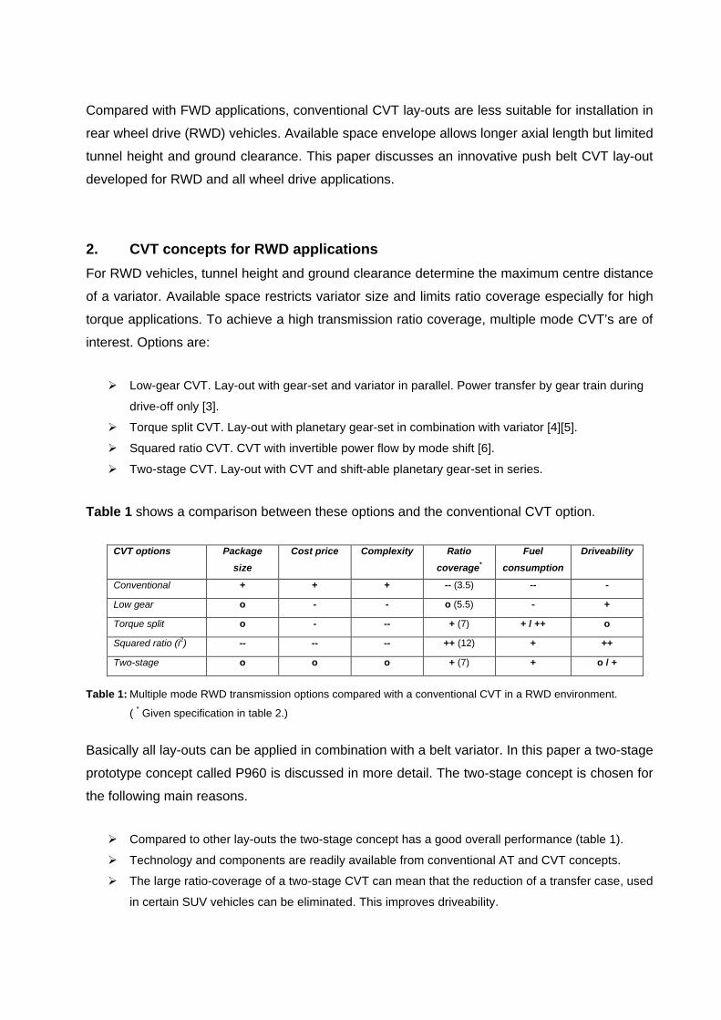
Figure 1 shows some typical torque and ratio coverage values for luxury cars and SUV’s that
are on the market today. The P960 prototype is also included in this figure.
Fig. 1: Torque and ratio coverage P960 concept and SUV and RWD vehicles on the market.
The P960 is a prototype with relatively small variator centre distance, developed to also answer
to luxury car space envelopes. With a two-stage CVT, specifically designed for SUV’s, larger
ratio coverage values of 7 to 10 are possible. AT drive-lines require a transfer case to obtain
these ratio coverage values. This offers the possibility to eliminate the transfer case reduction
or, in some cases, the complete transfer case.
The P960 transmission specifications can be found in table 2.
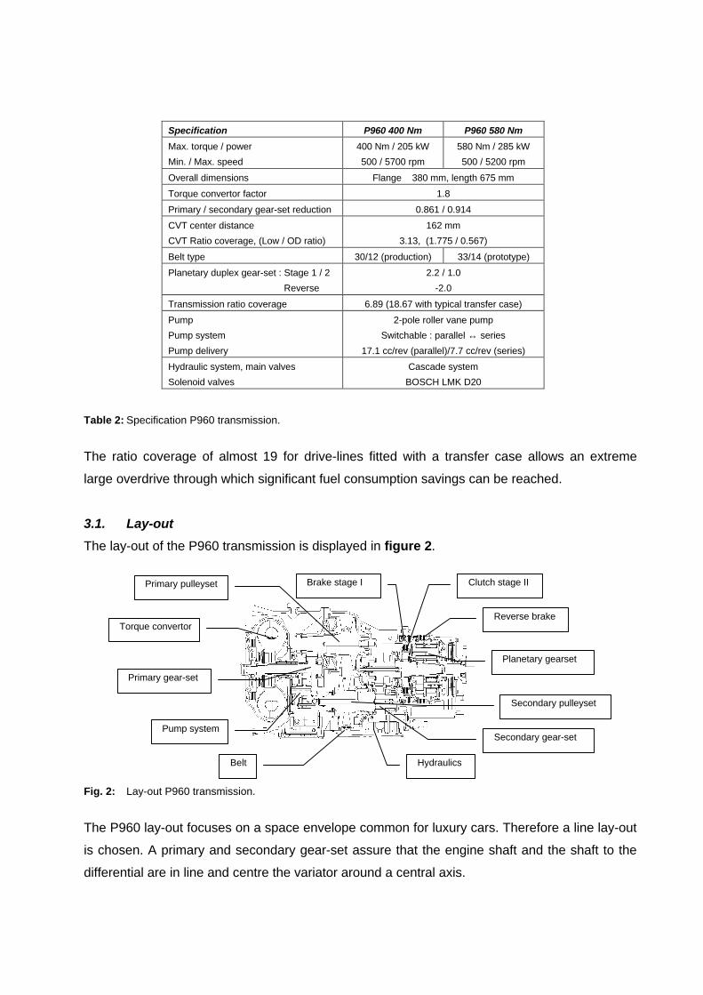
Table 2: Specification P960 transmission.
The ratio coverage of almost 19 for drive-lines fitted with a transfer case allows an extreme
large overdrive through which significant fuel consumption savings can be reached.
3.1. Lay-out
The lay-out of the P960 transmission is displayed in figure 2.
Fig. 2: Lay-out P960 transmission.
The P960 lay-out focuses on a space envelope common for luxury cars. Therefore a line lay-out
is chosen. A primary and secondary gear-set assure that the engine shaft and the shaft to the
differential are in line and centre the variator around a central axis.
Specification P960 400 Nm P960 580 Nm
Max. torque / power
Min. / Max. speed
400 Nm / 205 kW
500 / 5700 rpm
580 Nm / 285 kW
500 / 5200 rpm
Overall dimensions Flange ∅380 mm, length 675 mm
Torque convertor factor 1.8
Primary / secondary gear-set reduction 0.861 / 0.914
CVT center distance
CVT Ratio coverage, (Low / OD ratio)
162 mm
3.13, (1.775 / 0.567)
Belt type 30/12 (production) 33/14 (prototype)
Planetary duplex gear-set : Stage 1 / 2
Reverse
2.2 / 1.0
-2.0
Transmission ratio coverage 6.89 (18.67 with typical transfer case)
Pump
Pump system
Pump delivery
2-pole roller vane pump
Switchable : parallel ↔ series
17.1 cc/rev (parallel)/7.7 cc/rev (series)
Hydraulic system, main valves
Solenoid valves
Cascade system
BOSCH LMK D20
Torque convertor
Pump system
Belt Hydraulics
Secondary pulleyset
Planetary gearset
Reverse brake
Clutch stage IIBrake stage IPrimary pulleyset
Secondary gear-set
Primary gear-set

Torque convertor & pump drive
The 3-way torque convertor with lock-up is an off the shelf component. Right behind it a toothed
chain drive for the pump is positioned, shown in figure 3. Due to the small centre distance
between the sprockets a chain tensor is not required. The possibility to change the ratio leaves
room to optimise for different engine types having different oil requirements.
Pulleysets
The primary and secondary pulley-set of the variator are displayed in figure 3. To achieve a
compact design, the primary pulley is fitted with a double piston. Primary pressure is derived
from secondary pressure leading to a primary piston area that is a factor 2.4 larger than the
secondary piston area.
Fig. 3: Pump with pump-drive and primary and secondary pulley-set.
The secondary pulley has a single piston. To prevent over-clamping of the belt and undesired
down-shifts to Low at high secondary pulley speeds, this piston is fitted with a compensation
shield balancing pressure from the centrifugal effect working on the oil in the piston.
Planetary gear-set and clutches
Figure 4 shows the simplified lay-out of the transmission. The planetary gear-set at the rear end
is of the Ravignaux type. The gear-set contains three clutches/brakes. The following
configurations are possible:
q Drive in stage I. Brake I is engaged and connects sun-gear 2 with the transmission housing.
Reduction of the planetary set is 2.2.
q Drive in stage II. Clutch II is engaged and connects sun-gear 2 with sun-gear 1, providing a
direct drive. The total set rotates as a block with reduction 1.0.
q Reverse. The reverse brake is engaged and connects the ring gear with the transmission
housing. Rotation of the planet carrier is reversed. The reduction is –2.0.
Primary pulley
Secondary pulley

Fig. 4 Simplified lay-out P960 transmission and planetary gear unit.
Hydraulic system
To obtain a compact variator design with small pistons the maximum system pressure of 80 bar
lies above levels known from conventional CVT’s. The offline pump can be build small in
diameter introducing increased pump housing stiffness that avoids large internal leakage. The
pump system is discussed in section 3.3.
The transmission hydraulics are located in the sump. The hydraulic system is a cascade system
having different priority levels. The main pressure levels are shown in figure 5.
Fig. 5 P960 hydraulic system with LMK D20 BOSCH solenoid (example: normally high, leakage optimised).
Variator actuation and oil supply to the control unit are main priorities. In extreme conditions
where incidental oil shortage occurs, lubrication pressure is allowed to drop.
Control (A)
Supply (P)
Sump (T)
- Planetary sets- Clutch cooling- Gears/bearings- Torque convertor
- Lock-up- Mode shift clutches- Reverse brake
Primary pulley : 0 - 35 bar- Double piston surface
- Single piston surface
- Compensation shield- Pump shift
- Belt
Solenoids : 7.4 bar
- Primary valve (ratio)- Torque convertor- Clutch (stage 2)- Brake (stage 1)
- Secondary valve (clamping)
ControlControl
Pump system
Lubrication/Cooling : 3 - 10 bar
Auxiliary functions : 4 - 25 bar
Secondary pulley : 5 - 80 bar
Hydraulic unit Solenoid valve
REDUCTIONPRIMARY
TORQUE CONVERTER (3-WAY)
HYDRAULIC BODYFILTER
SECONDARYPULLEY
PRIMARYPULLEY
PUMP
REDUCTIONSECONDARY
(stage 1)
-direct)(stage 2

The control system is fitted with five BOSCH leakage optimised LMK D20 variable force
solenoid valves for the control of secondary, primary, lock-up, clutch and brake pressure. The
two-stage concept typically requires an extra solenoid valve for the additional clutch function.
A BOSCH 3-port on/off solenoid valve is used for the pump switch function.
Controls
The P960 transmission is a two-stage transmission comprising two variograms with a certain
overlap, resulting in one variogram with large ratio coverage. The P960 controller is equipped
with a mode shift function that synchronises variator and planetary gear-set ratio changes
during shifts between the two stages. This results in a smooth overall transmission ratio change.
This function, together with the more conventional CVT control functions, is shown in figure 6.
Fig. 6 Control functions P960 transmission.
A BOSCH transmission controller unit (TCU) controls the signals to the solenoid valves. The
mode shift software runs in an ETAS ES1000.2 rapid prototyping system and communicates via
an “Emulator-Tastkopf” (ETK) bypass with the TCU.
3.2. Mode shift
The two-stage concept basically consists out of a belt variator mounted before a two speed AT.
In this way the variogram of the CVT is extended to reach increased ratio coverage. Figure 7
shows the power routes through the transmission for both stages.
Fig. 7 Power routes through the P960 transmission for stages I and II (lock-up assumed closed).
Clamping forceVariator ratio
Clutches
Mode-shift
Variator
TC lockup clutchPump stage
Remaining
Transmission control functions
REDUCTIONPRIMARY
TORQUE CONVERTER (3-WAY)
BRAKE R
HYDRAULIC BODYFILTER
SECONDARYPULLEY
PRIMARYPULLEY
(stage 2-direct)
CLUTCH II
(stage 1)BRAKE I
PUMP
REDUCTIONSECONDARY
REDUCTIONPRIMARY
TORQUE CONVERTER (3-WAY)
BRAKE R
HYDRAULIC BODYFILTER
SECONDARYPULLEY
PRIMARYPULLEY
(stage 2-direct)
CLUTCH II
(stage 1)BRAKE I
PUMP
REDUCTIONSECONDARY
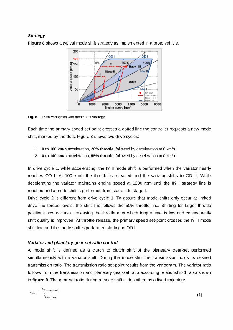
Strategy
Figure 8 shows a typical mode shift strategy as implemented in a proto vehicle.
Fig. 8 P960 variogram with mode shift strategy.
Each time the primary speed set-point crosses a dotted line the controller requests a new mode
shift, marked by the dots. Figure 8 shows two drive cycles:
1. 0 to 100 km/h acceleration, 20% throttle, followed by deceleration to 0 km/h
2. 0 to 140 km/h acceleration, 55% throttle, followed by deceleration to 0 km/h
In drive cycle 1, while accelerating, the I? II mode shift is performed when the variator nearly
reaches OD I. At 100 km/h the throttle is released and the variator shifts to OD II. While
decelerating the variator maintains engine speed at 1200 rpm until the II? I strategy line is
reached and a mode shift is performed from stage II to stage I.
Drive cycle 2 is different from drive cycle 1. To assure that mode shifts only occur at limited
drive-line torque levels, the shift line follows the 50% throttle line. Shifting for larger throttle
positions now occurs at releasing the throttle after which torque level is low and consequently
shift quality is improved. At throttle release, the primary speed set-point crosses the I? II mode
shift line and the mode shift is performed starting in OD I.
Variator and planetary gear-set ratio control
A mode shift is defined as a clutch to clutch shift of the planetary gear-set performed
simultaneously with a variator shift. During the mode shift the transmission holds its desired
transmission ratio. The transmission ratio set-point results from the variogram. The variator ratio
follows from the transmission and planetary gear-set ratio according relationship 1, also shown
in figure 9. The gear-set ratio during a mode shift is described by a fixed trajectory.
(1)setGear
onTransmissiVar i
ii
−
=
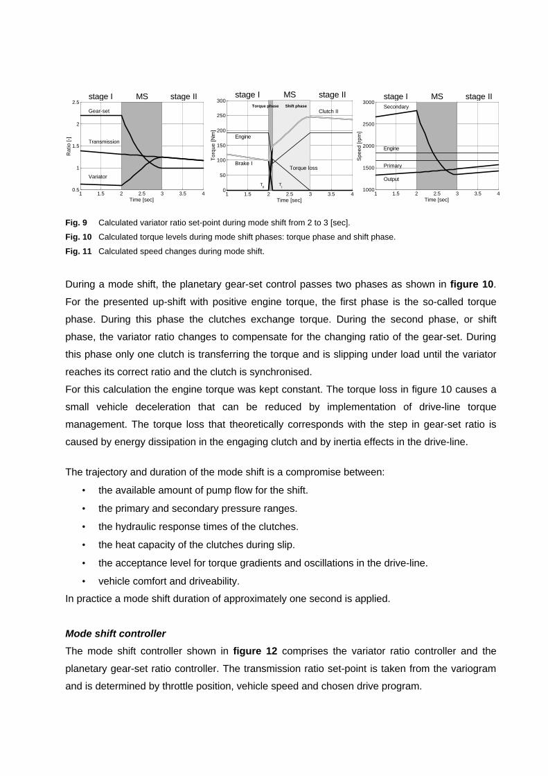
Fig. 9 Calculated variator ratio set-point during mode shift from 2 to 3 [sec].
Fig. 10 Calculated torque levels during mode shift phases: torque phase and shift phase.
Fig. 11 Calculated speed changes during mode shift.
During a mode shift, the planetary gear-set control passes two phases as shown in figure 10.
For the presented up-shift with positive engine torque, the first phase is the so-called torque
phase. During this phase the clutches exchange torque. During the second phase, or shift
phase, the variator ratio changes to compensate for the changing ratio of the gear-set. During
this phase only one clutch is transferring the torque and is slipping under load until the variator
reaches its correct ratio and the clutch is synchronised.
For this calculation the engine torque was kept constant. The torque loss in figure 10 causes a
small vehicle deceleration that can be reduced by implementation of drive-line torque
management. The torque loss that theoretically corresponds with the step in gear-set ratio is
caused by energy dissipation in the engaging clutch and by inertia effects in the drive-line.
The trajectory and duration of the mode shift is a compromise between:
• the available amount of pump flow for the shift.
• the primary and secondary pressure ranges.
• the hydraulic response times of the clutches.
• the heat capacity of the clutches during slip.
• the acceptance level for torque gradients and oscillations in the drive-line.
• vehicle comfort and driveability.
In practice a mode shift duration of approximately one second is applied.
Mode shift controller
The mode shift controller shown in figure 12 comprises the variator ratio controller and the
planetary gear-set ratio controller. The transmission ratio set-point is taken from the variogram
and is determined by throttle position, vehicle speed and chosen drive program.
1 1.5 2 2.5 3 3.5 40.5
1
1.5
2
2.5
Time [sec]
Rat
io [-
]
Gear-set
Transmission
Variator
stage I MS stage II
1 1.5 2 2.5 3 3.5 40
50
100
150
200
250
300
Time [sec]
Tor
que
[Nm
]
TII
TI
Torque phase Shift phase
Torque loss
Engine
Brake I
Clutch II
stage I MS stage II
1 1.5 2 2.5 3 3.5 41000
1500
2000
2500
3000
Time [sec]
Spe
ed [r
pm]
Secondary
Engine
Primary
Output
stage I MS stage II
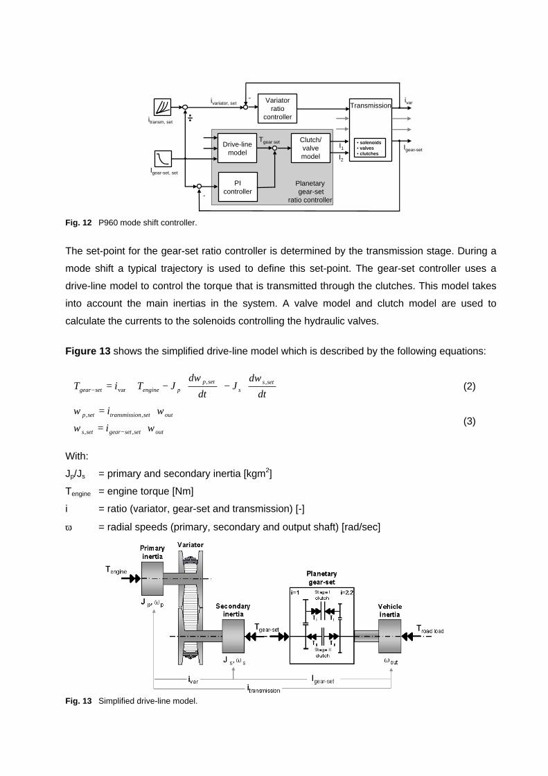
Fig. 12 P960 mode shift controller.
The set-point for the gear-set ratio controller is determined by the transmission stage. During a
mode shift a typical trajectory is used to define this set-point. The gear-set controller uses a
drive-line model to control the torque that is transmitted through the clutches. This model takes
into account the main inertias in the system. A valve model and clutch model are used to
calculate the currents to the solenoids controlling the hydraulic valves.
Figure 13 shows the simplified drive-line model which is described by the following equations:
(2)
(3)
With:
Jp/Js = primary and secondary inertia [kgm2]
Tengine = engine torque [Nm]
i = ratio (variator, gear-set and transmission) [-]
ω = radial speeds (primary, secondary and output shaft) [rad/sec]
Fig. 13 Simplified drive-line model.
PIcontroller
Drive-linemodel
-
TransmissionVariator
ratiocontroller
-
Clutch/valvemodel
Planetary gear-set
ratio controller
ivar
Igear-set
Igear-set, set
itransm, set
Tgear setI1I2
• solenoids• valves• clutches
ivariator, set
outsetsetgearsets
outsetontransmissisetp
setss
setppenginesetgear
i
i
dt
dJ
dt
dJTiT
ωω
ωω
ωω
⋅=
⋅=
⋅−
⋅−⋅=
−
−
,,
,,
,,var

3.3. Series-parallel pump concept
The P960 transmission contains a new pump concept comprising a two-pole roller vane pump
and a separate switch block. The double roller vane pump is chosen for the following reasons.
• It can cope with higher CVT pressures without directly requiring axial pressure compensation.
• It can cope with zero pressure as the rollers rely on centrifugal force for their sealing function.
• It can be made switchable. One pole is then made pressure-less which saves energy.
• It has a good cold start behaviour. At 150 rpm the rollers already centrifuge.
• It can cope with wear due to the self adjusting rollers.
Fig. 14: Schematic view 2-pole roller vane pump and hydraulic pump switch circuit.
The two-stage RWD concept imposes tough demands on the pumps displacement volume. An
important reason is the minimum engine speed which for vehicles in this segment can be as low
as 500 rpm, effectively reducing flow delivery of engine driven pumps to very low values.
The mode shift places a further demand on the pump. The displacement volume of the pump
needs to be increased to enable short shifting periods of variator and clutches, requiring flow
and pressure levels not common in conventional CVT’s.
The increased displacement volume of the pump presents significant energy losses at higher
engine speeds. For this reason a switchable concept has been developed. An hydraulic circuit,
shown in figure 14, allows the pump poles to be switched between two modes. A parallel mode
during which the pump system delivers maximum flow and a series mode during which the
pump delivers reduced flow. In series mode cavitation is prevented by creating an intermediate
pressure between the pump poles. This feature is especially useful for pumps with bigger rotor
diameter that have an increased risk on high speed cavitation. Examples are in-line pumps
mounted behind the torque convertor and pumps with somewhat larger displacement volumes.
The switch between the two modes can be made suddenly or gradually as figure 15 indicates.
CVT
Hydraulic circuit
Control
Roller
Carrier
Cam
Suction port
Discharge port

Fig. 15: Simplified hydraulic circuit modes, flow delivery, torque and power requirements at 20 [bar].
In series mode the larger pump pole is pressure feeding the smaller pump pole. The feed
pressure is controlled at approximately 2 bar by a pressure control valve. In this way high speed
cavitation is prevented in the smaller pump pole. The discharge pressure of 2 bar for the larger
pump pole is too small to cause cavitation damage.
Pump switches occur on the basis of flow evaluations in the controller. In case of oil abundance
the pump system is switched from parallel to series mode reducing oil deliverance from 17.1 to
7.7 cc/rev. At approaching oil shortage the pump system is switched back again.
Typically, pump switches occur at engine speeds between 1000 and 2000 rpm. In the chosen
hydraulic cascade circuit, pump flow variations influence secondary pressure and consequently
clamping force safety. It is important that during flow reductions secondary pressure remains
above acceptable levels. Pressure increase during flow increase is less significant.
Pressure dips are kept low by applying the strategy of a slowly switching pump system during
flow reduction. This leaves sufficient time for the secondary pressure control to adapt to the
changing amount of flow. In cases where a fast flow increase is required, for instance during a
mode shift request, the pump system switches faster to prevent oil shortages. Slow switching is
achieved by choosing the correct restrictions and pressure grooves in the pump switch circuit.
4. Vehicle tests and results
To do investigations under road conditions the P960 transmission was built in a GMC Yukon
vehicle. This section shows some test results performed to evaluate some of the new system
features. Table 3 shows the specification of this vehicle which originally is equipped with a 4-AT
transmission.
2 bar
CVT
CVT
Series mode
Parallel mode
0 1000 2000 3000 4000 5000 60000
20
40
60
80
100
120
Pump speed [rpm]
Flo
w [l
tr/m
in]
Flows
Parallel
Series
parallel (17.1 cc/rev)series (7.7 cc/rev)with on/off switchwith passive switchminimum speed
0 2000 4000 60000
1
2
3
4
5
6
Pump speed [rpm]
Pum
p to
rque
[Nm
]
Torque
Parallel
Series
0 2000 4000 60000
500
1000
1500
2000
2500
3000
3500
4000
Pump speed [rpm]
Hyd
raul
ic p
ower
[Wat
t] Power
Parallel
Series

Table 3: Specification GMC Yukon, vehicle, engine and AT transmission.
The original drive-line offers several possibilities that have been extended with the P960
transmission. Extended possibilities include step mode and drive program options. These are
available in all drive modes of the transfer case.
4.1. Mode shift results
Figure 16, 17, 18 and 19 show the results of a mode shift from stage I to stage II performed in
the vehicle under comparable conditions as used for the calculation results printed in figures 9
to 11. The measurement is done with a constant throttle position. The oscillations during the
presented mode shift result from an unstable clutch valve. This problem has been solved.
Fig. 16 Measured ratios and set-points. Fig. 17 Measured torque levels.
Fig. 18 Measured speeds. Fig. 19 Measured clutch pressures.
GMC Yukon
Vehicle Transmission + transfer case
Weight 2319 kg Transmission type 4-AT Hydra-Matic Transmission type P960 CVT
Max. speed 170 km/h Torque convertor Tc-factor ≈ 2 Torque convertor Tc-factor ≈ 1.8
Dimensions 505×207×196 cm Ratio coverage 4.40 (3.059 / 0.696) Ratio coverage 6.89 (3.13 × 2.2)
Transfer case ratio 2.71 / 1.0 Transfer case ratio 2.71 / 1.0
Engine Final reduction (diff) 3.73 Final reduction (diff) 3.73
Type 5.3 ltr V8 Speed @ 1000 rpm 12.5 – 54.6 km/h Speed @ 1000 rpm 12.4 – 85.1 km/h
Max. power 203 kW @ 5200 rpm
Max. torque 430 Nm @ 4000 rpm
Drive-line options:
Auto AWD
2 Hi
4 Hi
4 Lo
AT options
RWD + AWD spin
RWD
AWD road
AWD terrain
Drive-line options:
Auto AWD/2Hi/4Hi/4Lo
Step modes
Drive programs:
AT + CVT options
Economy, Comfort,
Sport, Stage I or II
The output speed of the transmission, shown in figure 18, maintains a fairly continuous level.
The torque losses due to energy dissipation in the clutches and changing speeds cause a drop
in output torque as can be seen in figure 17. As explained, engine torque management could
reduce this torque loss, resulting in even more comfortable mode shifts.
Figure 19 shows that during this stage I to stage II mode shift the pressure in clutch II increases
while the pressure in brake I is reduced. Both pressures follow their set-point generated by the
clutch/valve model in the mode shift controller quite well.
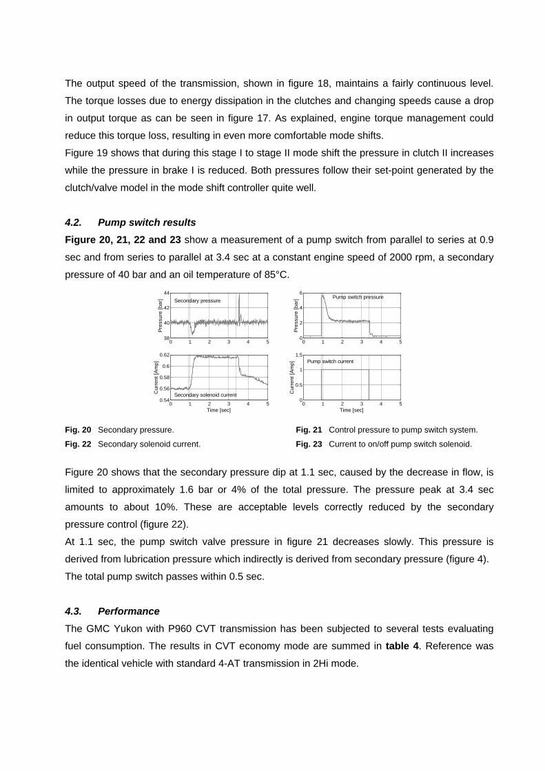
4.2. Pump switch results
Figure 20, 21, 22 and 23 show a measurement of a pump switch from parallel to series at 0.9
sec and from series to parallel at 3.4 sec at a constant engine speed of 2000 rpm, a secondary
pressure of 40 bar and an oil temperature of 85°C.
Fig. 20 Secondary pressure. Fig. 21 Control pressure to pump switch system.
Fig. 22 Secondary solenoid current. Fig. 23 Current to on/off pump switch solenoid.
Figure 20 shows that the secondary pressure dip at 1.1 sec, caused by the decrease in flow, is
limited to approximately 1.6 bar or 4% of the total pressure. The pressure peak at 3.4 sec
amounts to about 10%. These are acceptable levels correctly reduced by the secondary
pressure control (figure 22).
At 1.1 sec, the pump switch valve pressure in figure 21 decreases slowly. This pressure is
derived from lubrication pressure which indirectly is derived from secondary pressure (figure 4).
The total pump switch passes within 0.5 sec.
4.3. Performance
The GMC Yukon with P960 CVT transmission has been subjected to several tests evaluating
fuel consumption. The results in CVT economy mode are summed in table 4. Reference was
the identical vehicle with standard 4-AT transmission in 2Hi mode.
0 1 2 3 4 538
40
42
44
Pre
ssur
e [b
ar] Secondary pressure
0 1 2 3 4 50
2
4
6P
ress
ure
[bar
] Pump switch pressure
0 1 2 3 4 50.54
0.56
0.58
0.6
0.62
Time [sec]
Cur
rent
[Am
p]
Secondary solenoid current
0 1 2 3 4 50
0.5
1
1.5
Time [sec]
Cur
rent
[Am
p] Pump switch current

The tests were performed at Millford GM proving grounds.
Table 4: Fuel consumption measurements GMC Yukon with P960 transmission.
The measurements show considerable improvements especially for the highway cycle where
the large ratio coverage of the CVT shows its benefits.
5. Conclusions and recommendations
l The two-stage concept is an interesting option for rear wheel driven vehicles by means of its
lay-out and large ratio coverage.
l A two-stage push belt CVT with a ratio coverage of 6,9 has been developed and realised for
rear wheel drive applications up to 580 Nm.
l This transmission has been built and tested in an all wheel drive GMC Yukon with 430 Nm
engine torque. With the new transmission considerable fuel savings have been established
in this vehicle.
l A two-stage push belt CVT can, depending on application type, have the same ratio
coverage without transfer case reduction as an AT transmission with transfer case
reduction, offering driveability, cost and packaging advantages.
l The mode shift of the two-stage CVT effectively changes variator and gear-set ratio without
affecting overall transmission ratio, thus maintaining good driveability during the shift.
Output torque changes that occur during mode shifts can be reduced by introduction of
drive-line management.
l The two-stage concept requires a somewhat larger pump. This can easily be compensated
by using a switchable pump concept that reduces hydraulic losses with 55%. The chosen
series-parallel pump concept furthermore offers the advantage of cavitation prevention at
high engine speeds, especially useful for larger diameter pumps.
The designed and tested P960 two-stage CVT is a generally applicable prototype transmission
for RWD and AWD vehicles. This means that further optimisation remains possible. A dedicated
design for a chosen RWD or AWD vehicle will certainly reveal an even larger potential for the
two-stage push belt CVT.
Fuel consumption [l/100 km] (mpg)Cycle
Reference 4-AT P960 CVT, Economy
Fuel saving
[%]
FTP75 city 16.8 (14.0) 16.49 (14.3) 1.82
FFE highway 11.2 (21.0) 9.29 (25.3) 17.03
Combined 13.71 (17.2) 12.23 (19.2) 10.83

References
[1] Brandsma, A., van Lith, J,. Hendriks, E., "Push belt CVT developments for high power
applications", Proc. of CVT99, Eindhoven University of Technology 1999, pp.142-147.
[2] van der Sluis, F., Brandsma, A., "Stress reduction in push belt rings using residual
stresses", Proc. of CVT2002, VDI, Munich 2002, pp.383-402.
[3] Stockton, T., "The Ford research dual mode Continuously Variable Transmission”, Proc.
of SAE 1984, SAE841305.
[4] Markland, E., Comerford, K., "Dual mode improves CVT efficiency”, Proffesional
engineering, July-August 1991, pp. 27-28.
[5] Mucino, E., et al., "A continuously Variable Power Split Transmission for Automotive
Applications”, Proc. of SAE Detroit 1997, SAE970687.
[6] Heitmann, A., et al., "Das i2 Getriebe für den Autarken Hybrid”, Proc. of VDI, 1995, VDI
Berichte nr 1225 pp. 101-114.


![USER MANUAL Push Back Gateway U9920-GPB(EU) (P/N ...For more information consult the user manual for the belt station. Note: A non-VOX belt station [U9912-BSW(EU)] is recommended for](https://static.fdocuments.in/doc/165x107/60be99922922d853030735c8/user-manual-push-back-gateway-u9920-gpbeu-pn-for-more-information-consult.jpg)