The Toshiba Controls Manual - Диона –...
72
The TOSHIBA Controls Manual
-
Upload
truongdieu -
Category
Documents
-
view
254 -
download
0
Transcript of The Toshiba Controls Manual - Диона –...

The TOSHIBA Controls Manual
2
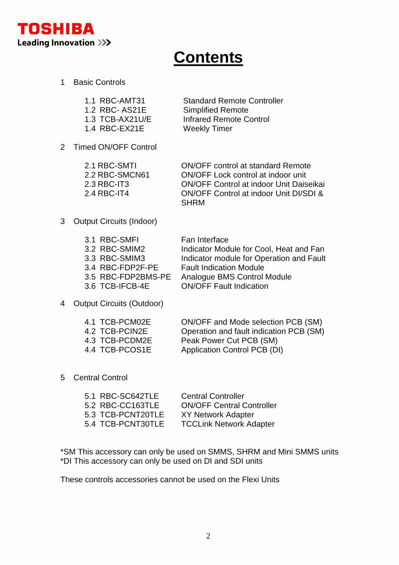
Contents
1 Basic Controls
1.1 RBC-AMT31 Standard Remote Controller 1.2 RBC- AS21E Simplified Remote 1.3 TCB-AX21U/E Infrared Remote Control 1.4 RBC-EX21E Weekly Timer
2 Timed ON/OFF Control
2.1 RBC-SMTI ON/OFF control at standard Remote 2.2 RBC-SMCN61 ON/OFF Lock control at indoor unit 2.3 RBC-IT3 ON/OFF Control at indoor Unit Daiseikai 2.4 RBC-IT4 ON/OFF Control at indoor Unit DI/SDI &
SHRM 3 Output Circuits (Indoor)
3.1 RBC-SMFI Fan Interface 3.2 RBC-SMIM2 Indicator Module for Cool, Heat and Fan 3.3 RBC-SMIM3 Indicator module for Operation and Fault 3.4 RBC-FDP2F-PE Fault Indication Module 3.5 RBC-FDP2BMS-PE Analogue BMS Control Module 3.6 TCB-IFCB-4E ON/OFF Fault Indication
4 Output Circuits (Outdoor)
4.1 TCB-PCM02E ON/OFF and Mode selection PCB (SM) 4.2 TCB-PCIN2E Operation and fault indication PCB (SM) 4.3 TCB-PCDM2E Peak Power Cut PCB (SM) 4.4 TCB-PCOS1E Application Control PCB (DI)
5 Central Control
5.1 RBC-SC642TLE Central Controller 5.2 RBC-CC163TLE ON/OFF Central Controller 5.3 TCB-PCNT20TLE XY Network Adapter 5.4 TCB-PCNT30TLE TCCLink Network Adapter
*SM This accessory can only be used on SMMS, SHRM and Mini SMMS units *DI This accessory can only be used on DI and SDI units These controls accessories cannot be used on the Flexi Units
3
6 Windows Control
6.1 Windows control Package 6.2 Windows Energy Monitoring 6.3 Windows Control and Other Equipment
7 Touch Screen
7.1 Touch screen Solution 8 . LonWorks
8.1 LonWorks Solution 9 BACnet
9.1 BACnet Solution 10 BEMS Solutions
10.1 TREND Solution 10.2 MODBUS Solution
11 VN Units
11.1 VN Unit Controls
4
1.1 RBC-AMT31 Standard Remote Controller
Description
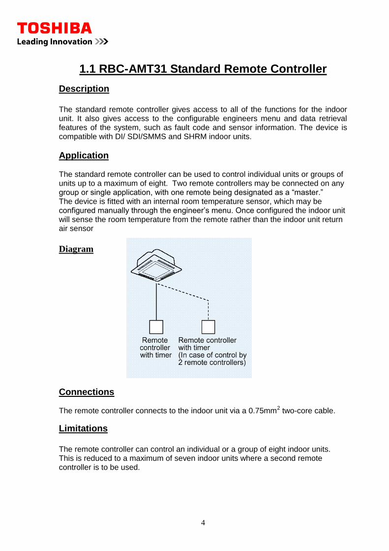
The standard remote controller gives access to all of the functions for the indoor unit. It also gives access to the configurable engineers menu and data retrieval features of the system, such as fault code and sensor information. The device is compatible with DI/ SDI/SMMS and SHRM indoor units.
Application
The standard remote controller can be used to control individual units or groups of units up to a maximum of eight. Two remote controllers may be connected on any group or single application, with one remote being designated as a “master.” The device is fitted with an internal room temperature sensor, which may be configured manually through the engineer’s menu. Once configured the indoor unit will sense the room temperature from the remote rather than the indoor unit return air sensor
Diagram
Connections The remote controller connects to the indoor unit via a 0.75mm2 two-core cable.
Limitations
The remote controller can control an individual or a group of eight indoor units. This is reduced to a maximum of seven indoor units where a second remote controller is to be used.

5
1.2 RBC- AS21E Simplified Remote
Description
The simplified remote controller is a reduced function remote controller. It allows the setting of all of the functions for the indoor unit, however the remote does not allow access to the engineer’s menu or data retrieval functions. Fault code information is displayed on the device, using format as the standard remote controller. Compatibility is with DI/SDI/SMMS and SHRM systems.
Application The simplified remote is used to control an individual indoor unit or a group of up to eight units. Two devices may be used to control individual or grouped units, where one device is configured to be a “master”. The devices are also equipped with internal room temperature sensors, which may be configured to take priority over the indoor unit return air sensor. This controller would commonly be used where simplified operation is beneficial, such as hotel room applications.
Diagram
Connections The remote controller connects to the indoor unit via a 0.75mm2 two-core cable.
Limitations
The remote controller can control an individual or a group of eight indoor units. This is reduced to a maximum of seven indoor units where a second remote controller is to be used.
6
1.3 Infrared Remote Control
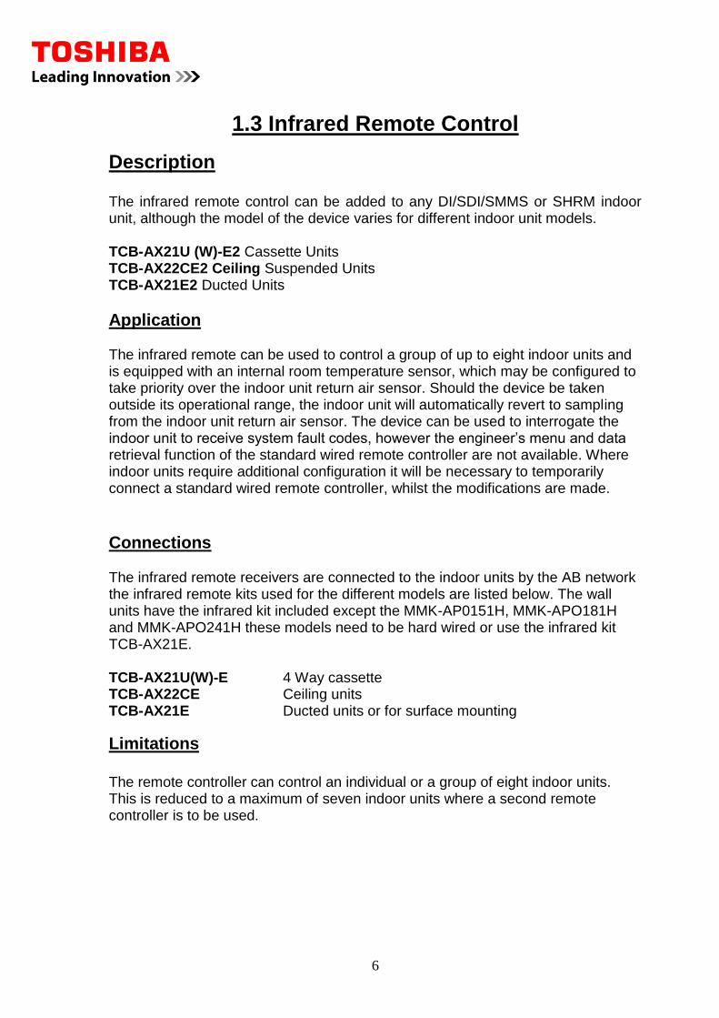
Description The infrared remote control can be added to any DI/SDI/SMMS or SHRM indoor unit, although the model of the device varies for different indoor unit models. TCB-AX21U (W)-E2 Cassette Units TCB-AX22CE2 Ceiling Suspended Units TCB-AX21E2 Ducted Units
Application The infrared remote can be used to control a group of up to eight indoor units and is equipped with an internal room temperature sensor, which may be configured to take priority over the indoor unit return air sensor. Should the device be taken outside its operational range, the indoor unit will automatically revert to sampling from the indoor unit return air sensor. The device can be used to interrogate the indoor unit to receive system fault codes, however the engineer’s menu and data retrieval function of the standard wired remote controller are not available. Where indoor units require additional configuration it will be necessary to temporarily connect a standard wired remote controller, whilst the modifications are made.
Connections The infrared remote receivers are connected to the indoor units by the AB network the infrared remote kits used for the different models are listed below. The wall units have the infrared kit included except the MMK-AP0151H, MMK-APO181H and MMK-APO241H these models need to be hard wired or use the infrared kit TCB-AX21E. TCB-AX21U(W)-E 4 Way cassette TCB-AX22CE Ceiling units TCB-AX21E Ducted units or for surface mounting
Limitations
The remote controller can control an individual or a group of eight indoor units. This is reduced to a maximum of seven indoor units where a second remote controller is to be used.
7
1.4 RBC-EX21E Weekly Timer
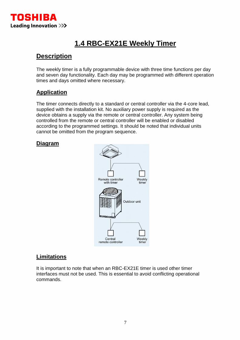
Description The weekly timer is a fully programmable device with three time functions per day and seven day functionality. Each day may be programmed with different operation times and days omitted where necessary.
Application The timer connects directly to a standard or central controller via the 4-core lead, supplied with the installation kit. No auxiliary power supply is required as the device obtains a supply via the remote or central controller. Any system being controlled from the remote or central controller will be enabled or disabled according to the programmed settings. It should be noted that individual units cannot be omitted from the program sequence.
Diagram
Limitations It is important to note that when an RBC-EX21E timer is used other timer interfaces must not be used. This is essential to avoid conflicting operational commands.
8
2.1 RBC-SMTI Timer Interface Lead
Description
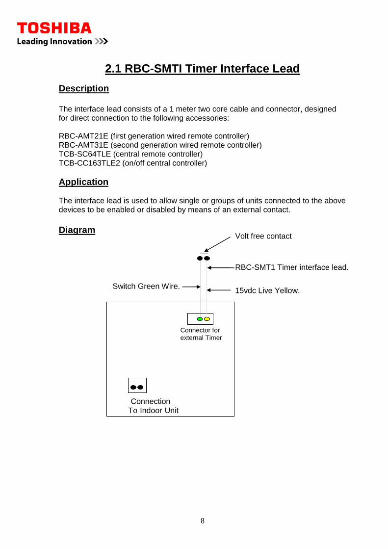
The interface lead consists of a 1 meter two core cable and connector, designed for direct connection to the following accessories: RBC-AMT21E (first generation wired remote controller) RBC-AMT31E (second generation wired remote controller) TCB-SC64TLE (central remote controller) TCB-CC163TLE2 (on/off central controller)
Application The interface lead is used to allow single or groups of units connected to the above devices to be enabled or disabled by means of an external contact.
Diagram
Connector for external Timer CN2
Connection To Indoor Unit
Switch Green Wire. 15vdc Live Yellow.
RBC-SMT1 Timer interface lead.
Volt free contact
9
Connections The interface lead is connected to the CN02 connection, which is also used for interfacing the Weekly Timer option (RBC-EXW21E).
Limitations
It should be noted that when the external contact is operated, all connected systems will be enabled or disabled, depending on whether the contact is opened or closed. Individual units cannot be omitted from the on/off control process. The interface lead may be extended to a maximum total length of 25 meters when using a screened cable, with a cross sectional area of 0.75mm.
10
2.2 RBC-SMCN61 ON/OFF Lock control at
Indoor unit
Description
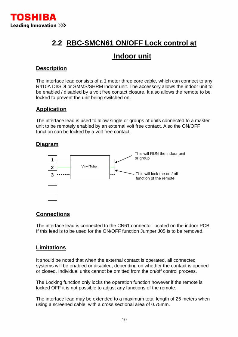
The interface lead consists of a 1 meter three core cable, which can connect to any R410A DI/SDI or SMMS/SHRM indoor unit. The accessory allows the indoor unit to be enabled / disabled by a volt free contact closure. It also allows the remote to be locked to prevent the unit being switched on.
Application The interface lead is used to allow single or groups of units connected to a master unit to be remotely enabled by an external volt free contact. Also the ON/OFF function can be locked by a volt free contact.
Diagram
Connections The interface lead is connected to the CN61 connector located on the indoor PCB. If this lead is to be used for the ON/OFF function Jumper J05 is to be removed.
Limitations
It should be noted that when the external contact is operated, all connected systems will be enabled or disabled, depending on whether the contact is opened or closed. Individual units cannot be omitted from the on/off control process. The Locking function only locks the operation function however if the remote is locked OFF it is not possible to adjust any functions of the remote. The interface lead may be extended to a maximum total length of 25 meters when using a screened cable, with a cross sectional area of 0.75mm.
1
2
3
Vinyl Tube
This will lock the on / off function of the remote
This will RUN the indoor unit or group
11
2.3 RBC-IT3 ON/OFF Control For DAISEIKAI
Description
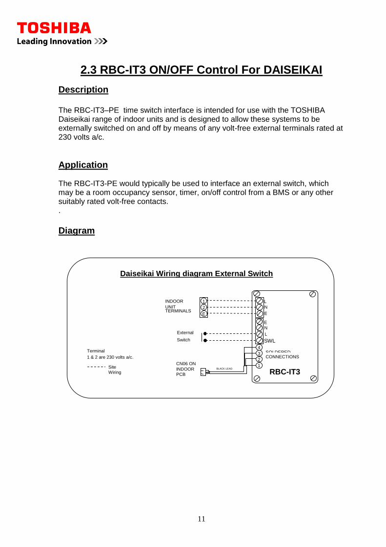
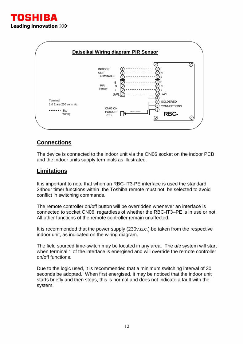
The RBC-IT3–PE time switch interface is intended for use with the TOSHIBA Daiseikai range of indoor units and is designed to allow these systems to be externally switched on and off by means of any volt-free external terminals rated at 230 volts a/c.
Application The RBC-IT3-PE would typically be used to interface an external switch, which may be a room occupancy sensor, timer, on/off control from a BMS or any other suitably rated volt-free contacts. .
Diagram
1 2 INDOOR
UNIT TERMINALS N L
4 3 2 1
RBC-IT3
SOLDERED CONNECTIONS
CN06 ON INDOOR PCB
BLACK LEAD 1.5m
External Switch
Daiseikai Wiring diagram External Switch
Terminals 1 & 2 are 230 volts a/c.
Site Wiring
E N
E L SWL
E E
12
Connections The device is connected to the indoor unit via the CN06 socket on the indoor PCB and the indoor units supply terminals as illustrated.
Limitations
It is important to note that when an RBC-IT3-PE interface is used the standard 24hour timer functions within the Toshiba remote must not be selected to avoid conflict in switching commands. The remote controller on/off button will be overridden whenever an interface is connected to socket CN06, regardless of whether the RBC-IT3–PE is in use or not. All other functions of the remote controller remain unaffected. It is recommended that the power supply (230v.a.c.) be taken from the respective indoor unit, as indicated on the wiring diagram. The field sourced time-switch may be located in any area. The a/c system will start when terminal 1 of the interface is energised and will override the remote controller on/off functions. Due to the logic used, it is recommended that a minimum switching interval of 30 seconds be adopted. When first energised, it may be noticed that the indoor unit starts briefly and then stops, this is normal and does not indicate a fault with the system.
1 2 INDOOR
UNIT TERMINALS N L
4 3 2 1
RBC-IT3
SOLDERED CONNECTIONS
CN06 ON INDOOR PCB
BLACK LEAD
1.5m
PIR
Sensor
Daiseikai Wiring diagram PIR Sensor
Terminals 1 & 2 are 230 volts a/c.
Site Wiring
E N E L SWL
E N E L
SWL
13
2.4 RBC-IT4 ON/OFF Control For DI/SDI/SMMS/SHRM
Description
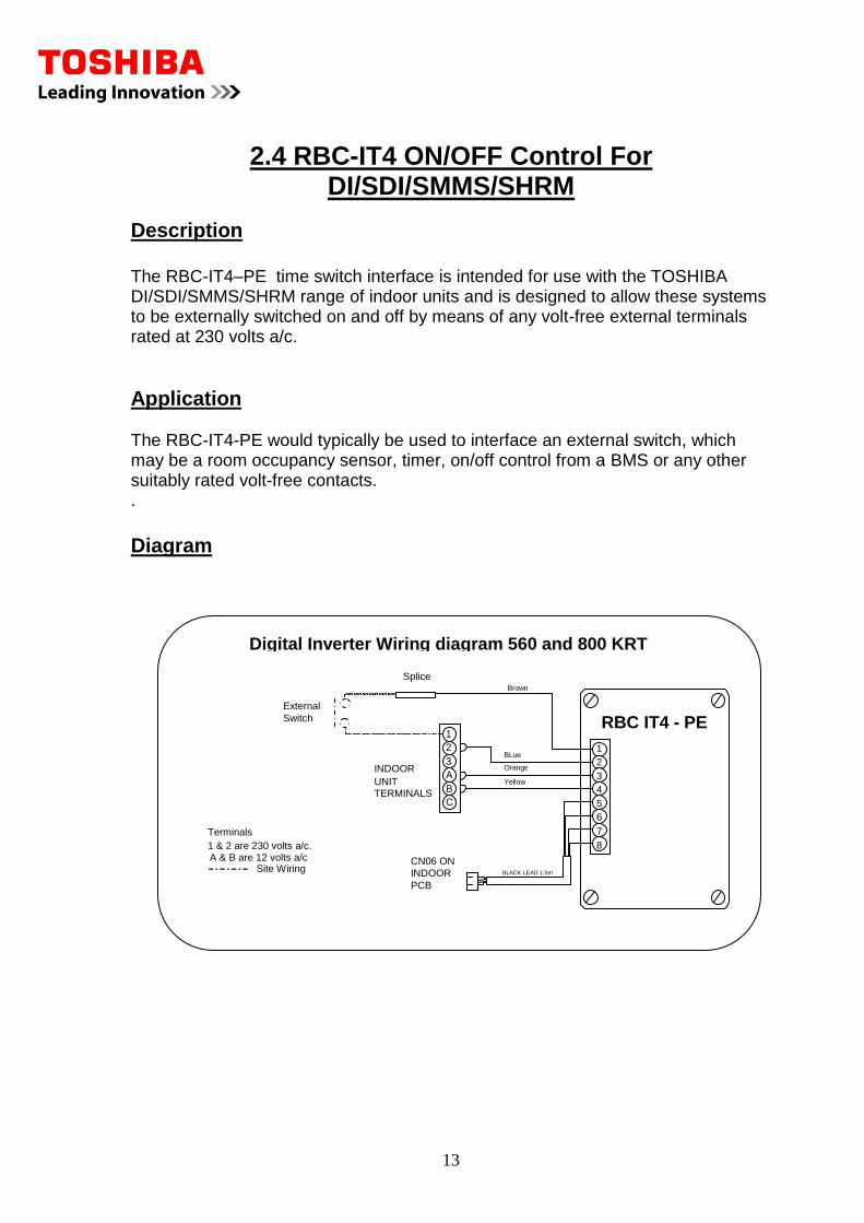
The RBC-IT4–PE time switch interface is intended for use with the TOSHIBA DI/SDI/SMMS/SHRM range of indoor units and is designed to allow these systems to be externally switched on and off by means of any volt-free external terminals rated at 230 volts a/c.
Application The RBC-IT4-PE would typically be used to interface an external switch, which may be a room occupancy sensor, timer, on/off control from a BMS or any other suitably rated volt-free contacts. .
Diagram
1 2 3 A B C
INDOOR UNIT
TERMINALS
1 2 3 4 5 6 7 8
RBC IT4 - PE
CN06 ON INDOOR PCB
BLACK LEAD 1.5m
External Switch
Digital Inverter Wiring diagram 560 and 800 KRT Wall Units
Splice Brown
BLue
Terminals 1 & 2 are 230 volts a/c.
Site Wiring
Orange
Yellow
A & B are 12 volts a/c
14
Connections
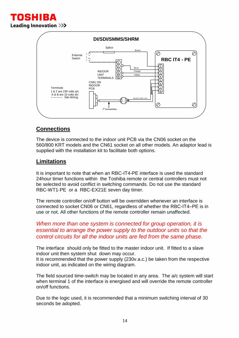
The device is connected to the indoor unit PCB via the CN06 socket on the 560/800 KRT models and the CN61 socket on all other models. An adaptor lead is supplied with the installation kit to facilitate both options.
Limitations
It is important to note that when an RBC-IT4-PE interface is used the standard 24hour timer functions within the Toshiba remote or central controllers must not be selected to avoid conflict in switching commands. Do not use the standard RBC-WT1-PE or a RBC-EX21E seven day timer. The remote controller on/off button will be overridden whenever an interface is connected to socket CN06 or CN61, regardless of whether the RBC-IT4–PE is in use or not. All other functions of the remote controller remain unaffected.
When more than one system is connected for group operation, it is essential to arrange the power supply to the outdoor units so that the control circuits for all the indoor units are fed from the same phase. The interface should only be fitted to the master indoor unit. If fitted to a slave indoor unit then system shut down may occur. It is recommended that the power supply (230v.a.c.) be taken from the respective indoor unit, as indicated on the wiring diagram. The field sourced time-switch may be located in any area. The a/c system will start when terminal 1 of the interface is energised and will override the remote controller on/off functions. Due to the logic used, it is recommended that a minimum switching interval of 30 seconds be adopted.
1 2 3 A B
INDOOR UNIT
TERMINALS
1 2 3 4 5 6 7 8
RBC IT4 - PE
CN61 ON INDOOR PCB
BLACK LEAD 1.5m
External Switch
DI/SDI/SMMS/SHRM Splice
Brown
BLue
Terminals 1 & 2 are 230 volts a/c.
Site Wiring
Orange
Yellow
A & B are 15 volts d/c
Converter lead
15
3.1 RBC-SMFI Fan Interface Module
Description
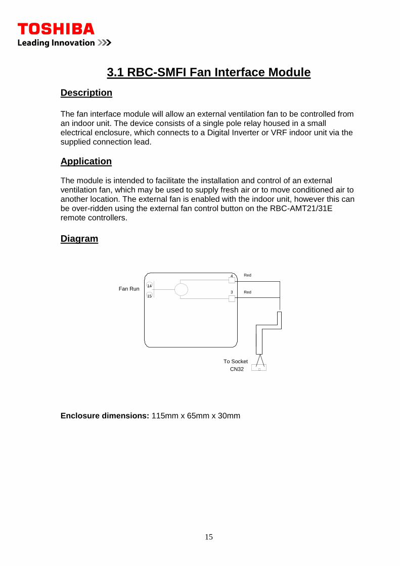
The fan interface module will allow an external ventilation fan to be controlled from an indoor unit. The device consists of a single pole relay housed in a small electrical enclosure, which connects to a Digital Inverter or VRF indoor unit via the supplied connection lead.
Application The module is intended to facilitate the installation and control of an external ventilation fan, which may be used to supply fresh air or to move conditioned air to another location. The external fan is enabled with the indoor unit, however this can be over-ridden using the external fan control button on the RBC-AMT21/31E remote controllers.
Diagram Enclosure dimensions: 115mm x 65mm x 30mm
CN32
Red 14 15
4 3 Fan Run
Red
To Socket
16
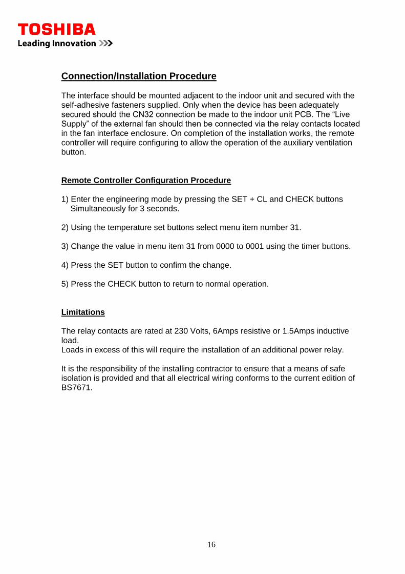
Connection/Installation Procedure The interface should be mounted adjacent to the indoor unit and secured with the self-adhesive fasteners supplied. Only when the device has been adequately secured should the CN32 connection be made to the indoor unit PCB. The “Live Supply” of the external fan should then be connected via the relay contacts located in the fan interface enclosure. On completion of the installation works, the remote controller will require configuring to allow the operation of the auxiliary ventilation button. Remote Controller Configuration Procedure 1) Enter the engineering mode by pressing the SET + CL and CHECK buttons Simultaneously for 3 seconds. 2) Using the temperature set buttons select menu item number 31. 3) Change the value in menu item 31 from 0000 to 0001 using the timer buttons. 4) Press the SET button to confirm the change. 5) Press the CHECK button to return to normal operation. Limitations The relay contacts are rated at 230 Volts, 6Amps resistive or 1.5Amps inductive load. Loads in excess of this will require the installation of an additional power relay. It is the responsibility of the installing contractor to ensure that a means of safe isolation is provided and that all electrical wiring conforms to the current edition of BS7671.
17
3.2 RBC-SMIM2 Indicator Module for Heat Cool or Fan Operation
Description
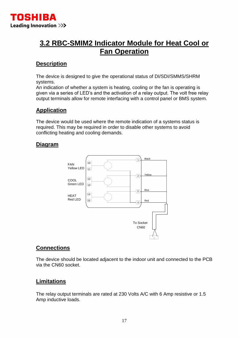
The device is designed to give the operational status of DI/SDI/SMMS/SHRM systems. An indication of whether a system is heating, cooling or the fan is operating is given via a series of LED’s and the activation of a relay output. The volt free relay output terminals allow for remote interfacing with a control panel or BMS system.
Application The device would be used where the remote indication of a systems status is required. This may be required in order to disable other systems to avoid conflicting heating and cooling demands.
Diagram
Connections The device should be located adjacent to the indoor unit and connected to the PCB via the CN60 socket.
Limitations
The relay output terminals are rated at 230 Volts A/C with 6 Amp resistive or 1.5 Amp inductive loads.
CN60
Red
10 11
1 FAN Yellow LED
Black
To Socket
4
Blue
12 13
2 COOL Green LED
Yellow
14 15
3 HEAT Red LED
18
3.3 RBC-SMIM3 Indicator Module For Operation & Fault
Description
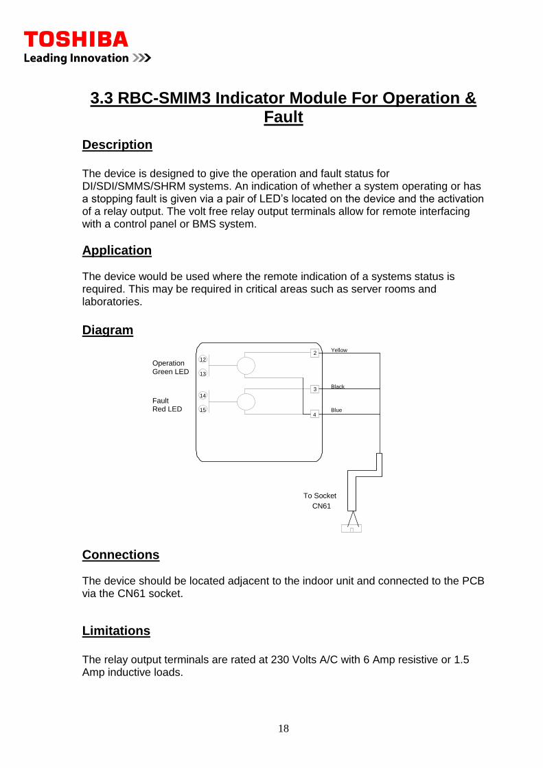
The device is designed to give the operation and fault status for DI/SDI/SMMS/SHRM systems. An indication of whether a system operating or has a stopping fault is given via a pair of LED’s located on the device and the activation of a relay output. The volt free relay output terminals allow for remote interfacing with a control panel or BMS system.
Application The device would be used where the remote indication of a systems status is required. This may be required in critical areas such as server rooms and laboratories.
Diagram
Connections The device should be located adjacent to the indoor unit and connected to the PCB via the CN61 socket.
Limitations
The relay output terminals are rated at 230 Volts A/C with 6 Amp resistive or 1.5 Amp inductive loads.
CN61
Blue
12 13
2 Operation Green LED
Yellow
To Socket
4 14 15
3 Fault Red LED
Black
19
3.4 RBC-FDP2F-PE Fault Display Panel
Description
The FDP is a module that has several different levels of operation in its most basic form will allow any fault on a unit to operate the relay to give an indication of a fault. The FDP has many built in functions to give preset operation, duty share / unit runs in fault. The device connects to a Digital Inverter or VRF indoor unit via the remote controller AB network.
Application The FDP2-F was principally designed to allow a fault condition to be transmitted to external systems via a relay contact. The FDP2 has several modes of operation these are configured by using the dipswitches SW1-7 they are as follows. Fault monitoring Fault monitoring + locked Cooling preset Fault monitoring + locked Heating preset Fault monitoring + locked Auto preset The FDP2-F has the ability to control two units in a duty share configuration the units will automatically change over on a 24hour basis and in the event of any fault both units will be enabled an FDP2-F is required for each indoor unit. FDP2-F can be networked to give advanced functionality the FDP2-F can be used as a group controller to control large groups of multiples of eight indoor units. The controller can linked to other Realtime controls products to give stand-alone BMS applications for retail or residential applications. Further details of advanced control options are available on request.
20
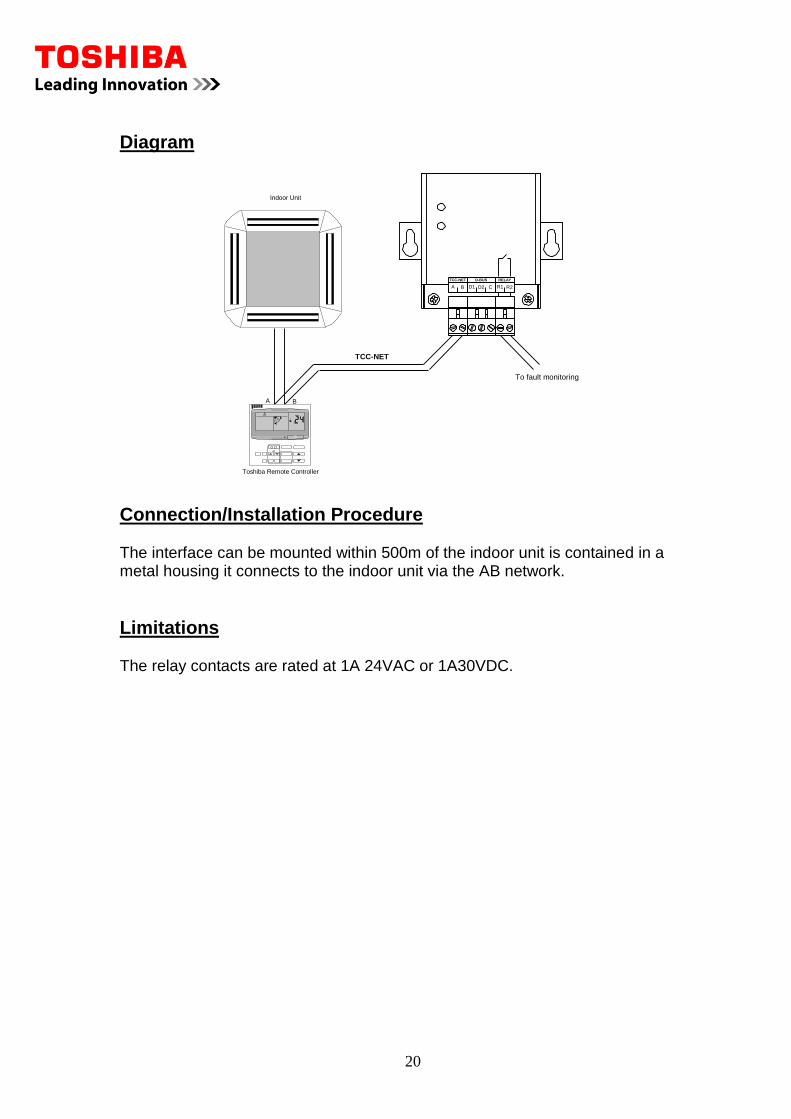
Diagram
TCC-NET
Indoor Unit
To fault monitoring
TCC-NET D-BUS RELAY
A B D1 D2 R1 R2C
Toshiba Remote Controller
A B
Connection/Installation Procedure The interface can be mounted within 500m of the indoor unit is contained in a metal housing it connects to the indoor unit via the AB network.
Limitations The relay contacts are rated at 1A 24VAC or 1A30VDC.
21
3.5 RBC-FDP2BMS-PE Analogue BMS Control Module
Description
The FDP2- BMS is an interface that has the ability to accept inputs from an analogue BMS system. The inputs to the controller can be either voltage or resistance this can be configured on the FDP2-BMS. The device also has a relay output that closes in the event of a fault within the system.
Application The FDP2-BMS has been designed to give a straightforward BMS solution it accepts voltage or restive inputs to set the following functions on the air conditioner. Set point, Fan speed, Mode, Louver, On/Off and local remote Lock the inputs for these functions can be configured to be 0 to 10Volt or 0 to 10Kohms restive. A dipswitch SW1 selects the mode. If the inputs go open circuit the FDP2-BMS assumes a default value for that input. This is useful in the event of a failure in the BMS inputs to the device. The FDP2-BMS can be customized to suit particular applications for a hotel or residential applicants where a specific control is required. An example is the set back requirements from a key card or a switch plate to match other electrical accessories in the room. FDP2-BMS can be networked to give advanced functionality the FDP2-BMS can be used as a group controller to control large groups of multiples of eight indoor units. The controller can linked to other Realtime controls products to give stand-alone BMS applications for retail or residential applications. Further details of advanced control options are available on request.
22
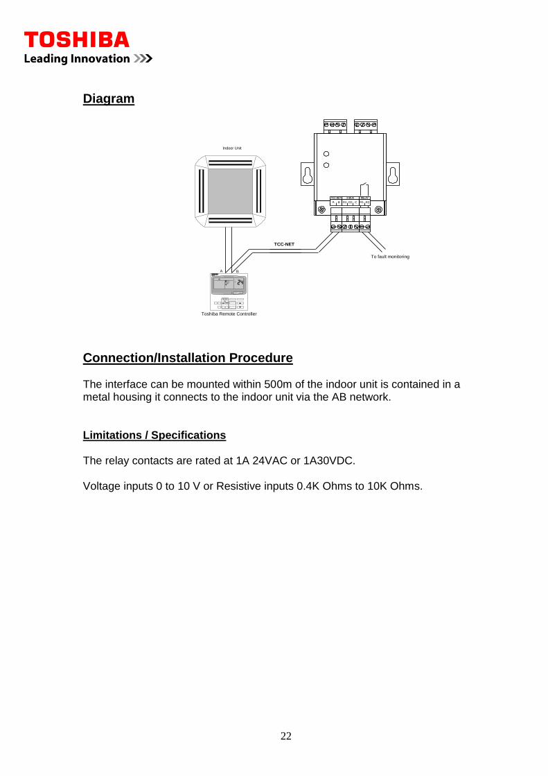
Diagram
TCC-NET
Indoor Unit
To fault monitoring
TCC-NET D-BUS RELAY
A B D1 D2 R1 R2C
Toshiba Remote Controller
A B
Connection/Installation Procedure The interface can be mounted within 500m of the indoor unit is contained in a metal housing it connects to the indoor unit via the AB network. Limitations / Specifications The relay contacts are rated at 1A 24VAC or 1A30VDC. Voltage inputs 0 to 10 V or Resistive inputs 0.4K Ohms to 10K Ohms.
23
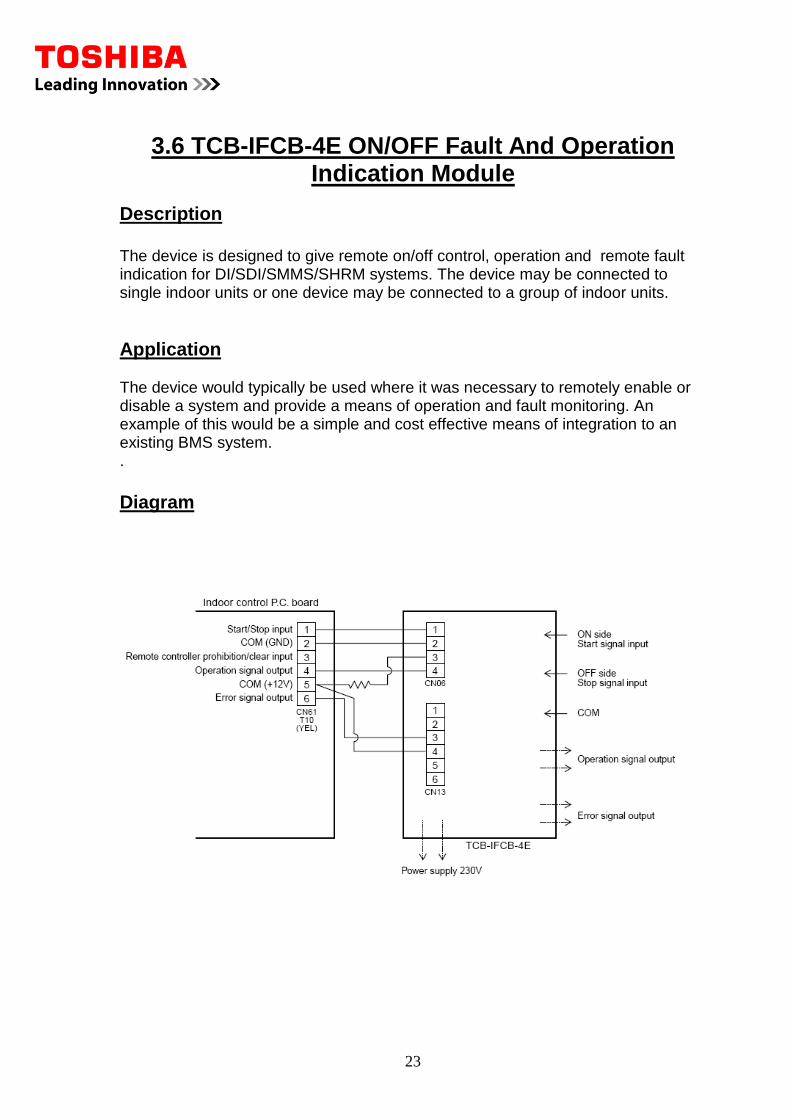
3.6 TCB-IFCB-4E ON/OFF Fault And Operation Indication Module
Description
The device is designed to give remote on/off control, operation and remote fault indication for DI/SDI/SMMS/SHRM systems. The device may be connected to single indoor units or one device may be connected to a group of indoor units.
Application The device would typically be used where it was necessary to remotely enable or disable a system and provide a means of operation and fault monitoring. An example of this would be a simple and cost effective means of integration to an existing BMS system. .
Diagram
24
Connections The device is enclosed in a galvanized steel enclosure, which should be mounted adjacent to the indoor unit and connected to the indoor PCB via the CN61 socket. The power supply for the device is obtained from the indoor unit supply terminals.
Limitations
The output contacts for operation/fault indication are limited to 230 Volts and 0.5 Amps. ON/OFF control cabling is limited to 500m using 2-core 0.75mm2 cable. Operation/fault output cabling is limited to 200m when using 3-core 0.75mm2 cable or 400m when using 1.5mm2 cable. Enclosure Dimensions: 66 x 170 x 200
25
4.1 TCB-PCM02E On/Off And Mode Selection PCB
Description
The accessory is designed to fit into the SMMS or SHRM outdoor unit; it is a PCB that can be used to perform several different functions. The PCB accepts an input that would be volt free from an external source to enable the required function.
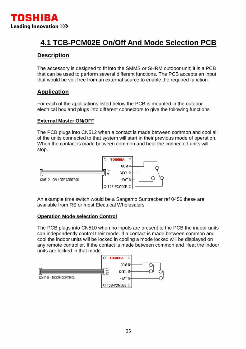
Application For each of the applications listed below the PCB is mounted in the outdoor electrical box and plugs into different connectors to give the following functions External Master ON/OFF The PCB plugs into CN512 when a contact is made between common and cool all of the units connected to that system will start in their previous mode of operation. When the contact is made between common and heat the connected units will stop.
An example time switch would be a Sangamo Suntracker ref 0456 these are available from RS or most Electrical Wholesalers Operation Mode selection Control The PCB plugs into CN510 when no inputs are present to the PCB the indoor units can independently control their mode. If a contact is made between common and cool the indoor units will be locked in cooling a mode locked will be displayed on any remote controller. If the contact is made between common and Heat the indoor units are locked in that mode.
26
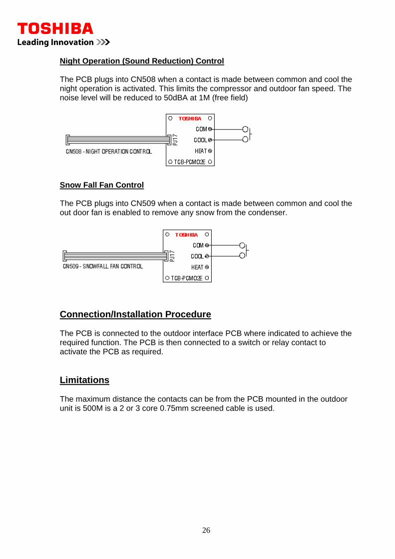
Night Operation (Sound Reduction) Control The PCB plugs into CN508 when a contact is made between common and cool the night operation is activated. This limits the compressor and outdoor fan speed. The noise level will be reduced to 50dBA at 1M (free field)
Snow Fall Fan Control The PCB plugs into CN509 when a contact is made between common and cool the out door fan is enabled to remove any snow from the condenser.
Connection/Installation Procedure The PCB is connected to the outdoor interface PCB where indicated to achieve the required function. The PCB is then connected to a switch or relay contact to activate the PCB as required.
Limitations The maximum distance the contacts can be from the PCB mounted in the outdoor unit is 500M is a 2 or 3 core 0.75mm screened cable is used.
27
4.2 TCB-PCIN2E Operations And Fault Indication
PCB
Description
The device is designed for use on the SMMS/SHRM systems and consists of a PCB, which provides a relay contact closure when the system is operating or in the event of a fault.
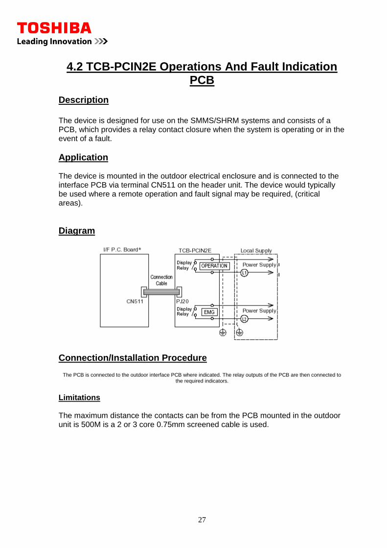
Application The device is mounted in the outdoor electrical enclosure and is connected to the interface PCB via terminal CN511 on the header unit. The device would typically be used where a remote operation and fault signal may be required, (critical areas).
Diagram
Connection/Installation Procedure
The PCB is connected to the outdoor interface PCB where indicated. The relay outputs of the PCB are then connected to the required indicators.
Limitations The maximum distance the contacts can be from the PCB mounted in the outdoor unit is 500M is a 2 or 3 core 0.75mm screened cable is used.
28
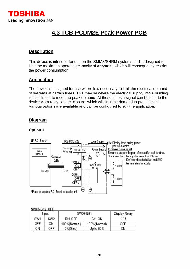
4.3 TCB-PCDM2E Peak Power PCB
Description
This device is intended for use on the SMMS/SHRM systems and is designed to limit the maximum operating capacity of a system, which will consequently restrict the power consumption.
Application The device is designed for use where it is necessary to limit the electrical demand of systems at certain times. This may be where the electrical supply into a building is insufficient to meet the peak demand. At these times a signal can be sent to the device via a relay contact closure, which will limit the demand to preset levels. Various options are available and can be configured to suit the application.
Diagram Option 1
29
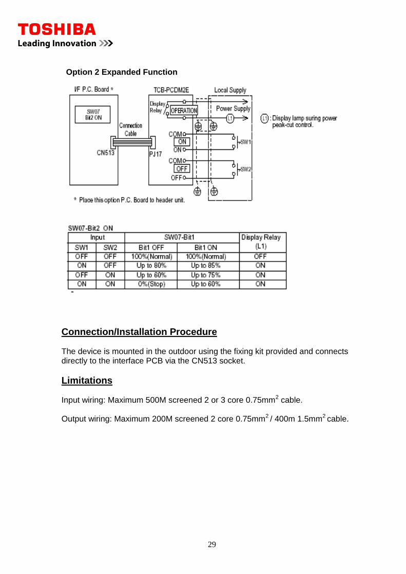
Option 2 Expanded Function
Connection/Installation Procedure The device is mounted in the outdoor using the fixing kit provided and connects directly to the interface PCB via the CN513 socket.
Limitations Input wiring: Maximum 500M screened 2 or 3 core 0.75mm2 cable.
Output wiring: Maximum 200M screened 2 core 0.75mm2 / 400m 1.5mm2 cable.
30
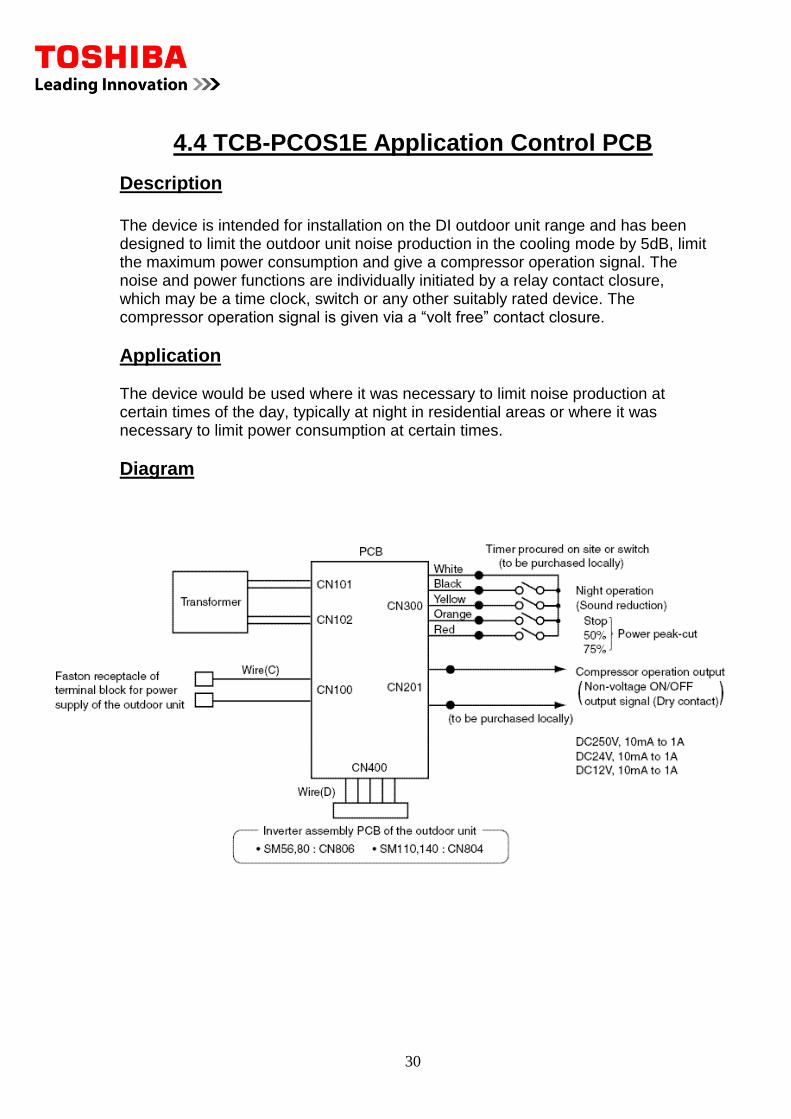
4.4 TCB-PCOS1E Application Control PCB
Description
The device is intended for installation on the DI outdoor unit range and has been designed to limit the outdoor unit noise production in the cooling mode by 5dB, limit the maximum power consumption and give a compressor operation signal. The noise and power functions are individually initiated by a relay contact closure, which may be a time clock, switch or any other suitably rated device. The compressor operation signal is given via a “volt free” contact closure.
Application The device would be used where it was necessary to limit noise production at certain times of the day, typically at night in residential areas or where it was necessary to limit power consumption at certain times.
Diagram

31
Connection/Installation Procedure The PCB and power transformer are mounted in the outdoor unit using the installation kit provided. Electrical connections are required to the outdoor unit supply terminals and the inverter assembly using the connectors supplied.
Limitations Compressor operation contacts are rated at 12-250VDC 10mA-1A Power peak control is in three stages: 0% 50% 75% Only one power peak option may be selected at any one time.
32
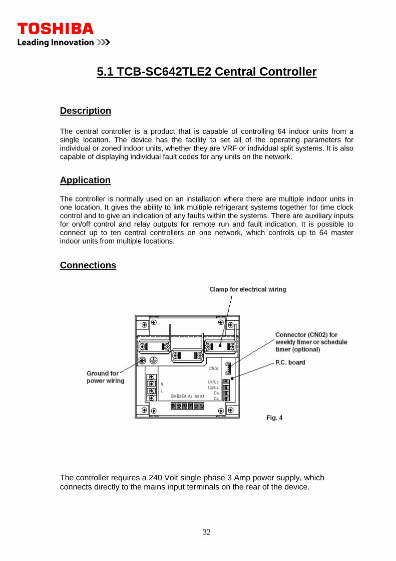
5.1 TCB-SC642TLE2 Central Controller
Description
The central controller is a product that is capable of controlling 64 indoor units from a single location. The device has the facility to set all of the operating parameters for individual or zoned indoor units, whether they are VRF or individual split systems. It is also capable of displaying individual fault codes for any units on the network.
Application The controller is normally used on an installation where there are multiple indoor units in one location. It gives the ability to link multiple refrigerant systems together for time clock control and to give an indication of any faults within the systems. There are auxiliary inputs for on/off control and relay outputs for remote run and fault indication. It is possible to connect up to ten central controllers on one network, which controls up to 64 master indoor units from multiple locations.
Connections
The controller requires a 240 Volt single phase 3 Amp power supply, which connects directly to the mains input terminals on the rear of the device.
33
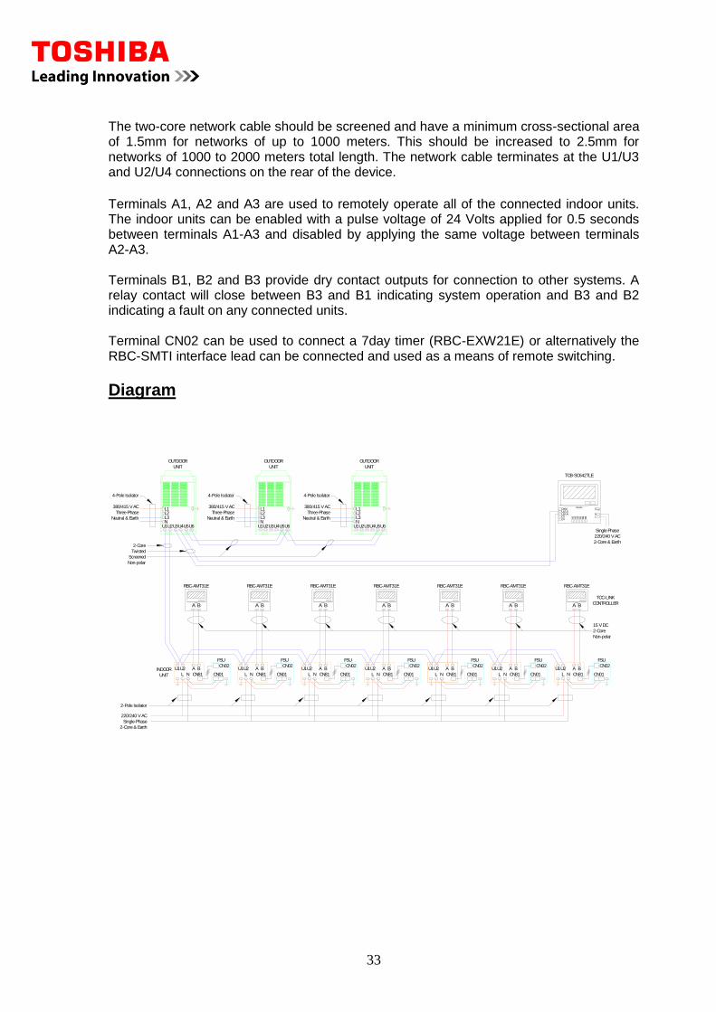
The two-core network cable should be screened and have a minimum cross-sectional area of 1.5mm for networks of up to 1000 meters. This should be increased to 2.5mm for networks of 1000 to 2000 meters total length. The network cable terminates at the U1/U3 and U2/U4 connections on the rear of the device.
Terminals A1, A2 and A3 are used to remotely operate all of the connected indoor units. The indoor units can be enabled with a pulse voltage of 24 Volts applied for 0.5 seconds between terminals A1-A3 and disabled by applying the same voltage between terminals A2-A3. Terminals B1, B2 and B3 provide dry contact outputs for connection to other systems. A relay contact will close between B3 and B1 indicating system operation and B3 and B2 indicating a fault on any connected units. Terminal CN02 can be used to connect a 7day timer (RBC-EXW21E) or alternatively the RBC-SMTI interface lead can be connected and used as a means of remote switching.
Diagram
INDOOR A B
L N
U1U2
2-Core & Earth
Single-Phase
220/240 V AC
2-Pole Isolator
2-Core
CN01
CN02
CN81
FSU
U2U1
NL
BA A B
L N
U1U2 A BL N
U1U2 U2U1
NL
BA U2U1
NL
BA
TOSHIBA
CN02U1/U3U2/U4C3C4 A
1A2
A3
B1
B2
B3
NL
E
TCB-SC642TLE
220/240 V AC
Single Phase
2-Core & Earth
Screened
Twisted
Non-polar
Neutral & Earth
380/415 V AC
Three-Phase
RBC-AMT31E
A B
L N
U1U2
Non-polar
CONTROLLER
TCC-LINK
2-Core
15 V DC
UNIT
U2U1 U3U4 U6U5
L1L2L3N
UNIT
OUTDOOR
4-Pole Isolator 4-Pole Isolator
OUTDOOR
UNIT
NL3L2L1
U5U6U4U3U1U2
Three-Phase
380/415 V AC
Neutral & Earth Neutral & Earth
380/415 V AC
Three-Phase
U2U1 U3U4 U6U5
L1L2L3N
UNIT
OUTDOOR
4-Pole Isolator
FSU
CN02
CN01CN81
FSU
CN02
CN01CN81
FSU
CN02
CN01CN81
FSU
CN02
CN01CN81
FSU
CN02
CN01CN81
FSU
CN02
CN01CN81
TOSHIBA
A BTOSHIBA
A BTOSHIBA
A BTOSHIBA
A BTOSHIBA
A B
RBC-AMT31E RBC-AMT31E RBC-AMT31E RBC-AMT31ERBC-AMT31E
TOSHIBA
A B
RBC-AMT31E
TOSHIBA
A B
34
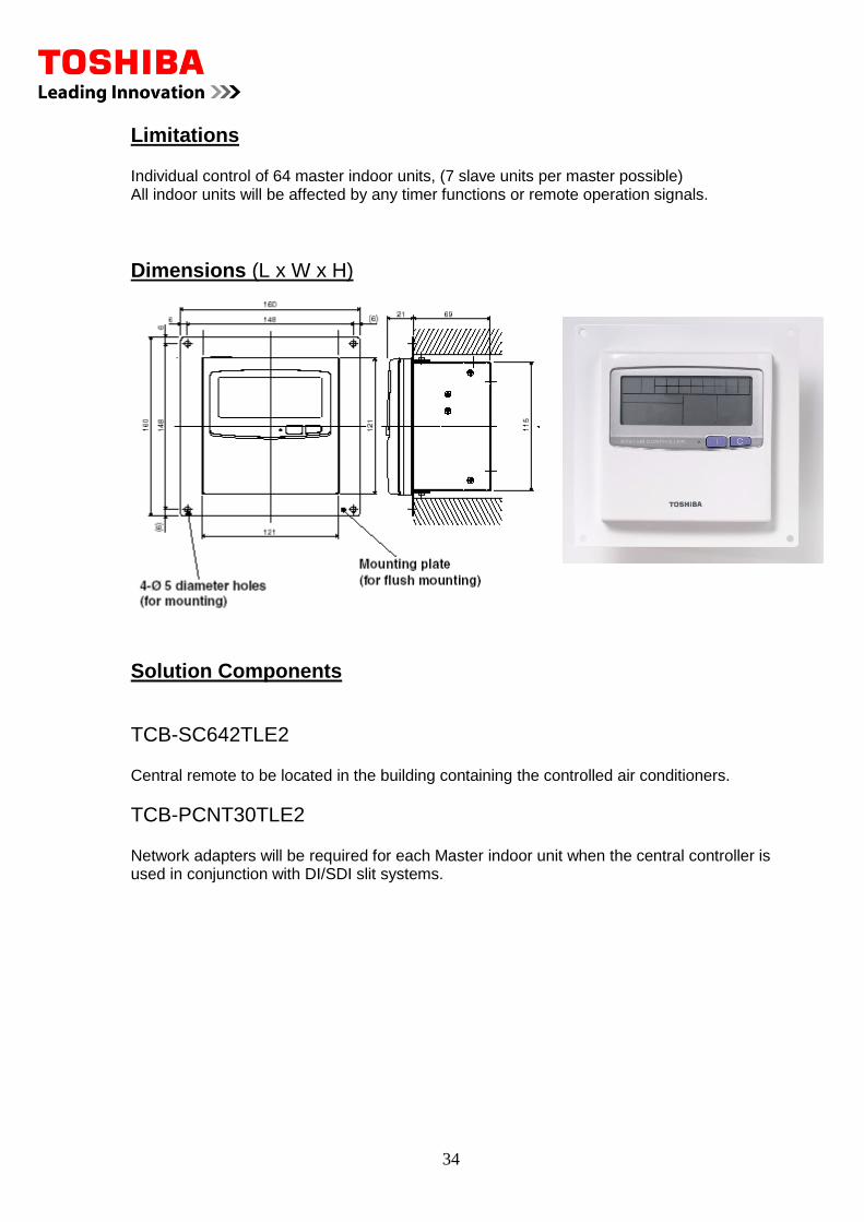
Limitations Individual control of 64 master indoor units, (7 slave units per master possible) All indoor units will be affected by any timer functions or remote operation signals.
Dimensions (L x W x H)
Solution Components
TCB-SC642TLE2 Central remote to be located in the building containing the controlled air conditioners.
TCB-PCNT30TLE2 Network adapters will be required for each Master indoor unit when the central controller is used in conjunction with DI/SDI slit systems.
35
5.2 RBC-CC163TLE2 ON/OFF Controller
Description
The on/off controller is a product that is capable of operating 16 indoor units from a single location. The device consists of 16 individual on/off buttons, which allows any connected units to be enabled or disabled via a single button operation. It is also possible to enable or disable all of the connected units via single button operation.
Application The device is ideally suited to locations where it may be necessary to remotely enable or disable indoor units. An example of this would be a hotel reception desk, where the receptionist may wish to enable a customer’s room air conditioning during the check-in process or disable it on the departure of a customer. Each of the on/off buttons has a label facility and again using the example of a hotel installation, the buttons could be labeled with a room number. For larger installations up to 4 controllers could be installed on one network, thus allowing 64 master indoor units to be controlled from one location. The device also has the facility for interfacing time clock control, remote switching, remote run signal and remote fault indication from a set of auxiliary contacts.
Connections
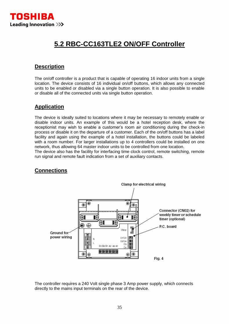
The controller requires a 240 Volt single phase 3 Amp power supply, which connects directly to the mains input terminals on the rear of the device.
36
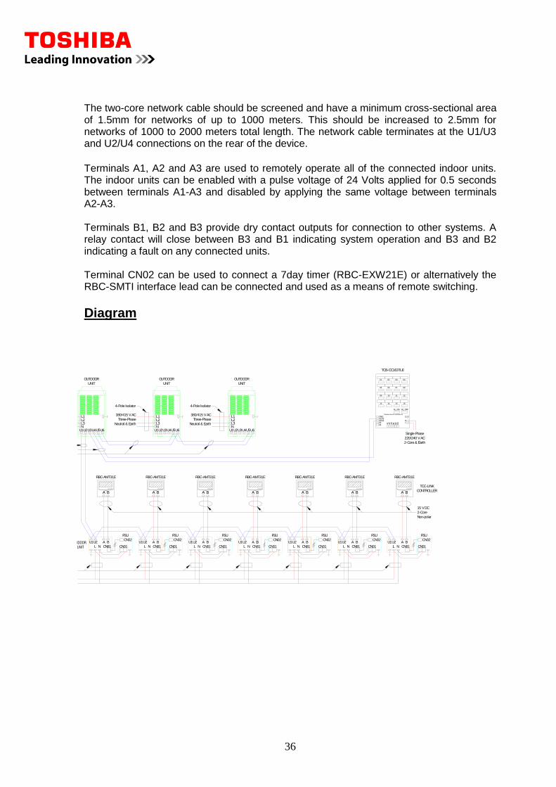
The two-core network cable should be screened and have a minimum cross-sectional area of 1.5mm for networks of up to 1000 meters. This should be increased to 2.5mm for networks of 1000 to 2000 meters total length. The network cable terminates at the U1/U3 and U2/U4 connections on the rear of the device.
Terminals A1, A2 and A3 are used to remotely operate all of the connected indoor units. The indoor units can be enabled with a pulse voltage of 24 Volts applied for 0.5 seconds between terminals A1-A3 and disabled by applying the same voltage between terminals A2-A3. Terminals B1, B2 and B3 provide dry contact outputs for connection to other systems. A relay contact will close between B3 and B1 indicating system operation and B3 and B2 indicating a fault on any connected units. Terminal CN02 can be used to connect a 7day timer (RBC-EXW21E) or alternatively the RBC-SMTI interface lead can be connected and used as a means of remote switching.
Diagram
A B
L N
U1U2
CN01
CN02
CN81
FSU
U2U1
NL
BA A B
L N
U1U2 A BL N
U1U2 U2U1
NL
BA U2U1
NL
BA
RBC-AMT31E
A B
L N
U1U2
Non-polar
CONTROLLER
TCC-LINK
2-Core
15 V DC
U2U1 U3U4 U6U5
L1L2L3N
UNIT
OUTDOOR
4-Pole Isolator
OUTDOOR
UNIT
NL3L2L1
U5U6U4U3U1U2
Three-Phase
380/415 V AC
Neutral & Earth Neutral & Earth
380/415 V AC
Three-Phase
U2U1 U3U4 U6U5
L1L2L3N
UNIT
OUTDOOR
4-Pole Isolator
FSU
CN02
CN01CN81
FSU
CN02
CN01CN81
FSU
CN02
CN01CN81
FSU
CN02
CN01CN81
FSU
CN02
CN01CN81
FSU
CN02
CN01CN81
TOSHIBA
A BTOSHIBA
A BTOSHIBA
A BTOSHIBA
A BTOSHIBA
A B
RBC-AMT31E RBC-AMT31E RBC-AMT31E RBC-AMT31ERBC-AMT31E
TOSHIBA
A B
RBC-AMT31E
TOSHIBA
A B
2-Core & Earth
Single Phase
220/240 V AC
TCB-CC163TLE
E
LN
B3
B2
B1
A3
A2
A1
C4C3U2/U4U1/U3CN02
TOSHIBA ON-OFF CONTROLLER
01 02 03 04
08070605
09 10 11 12
16151413
ALL ON ALL OFF
37
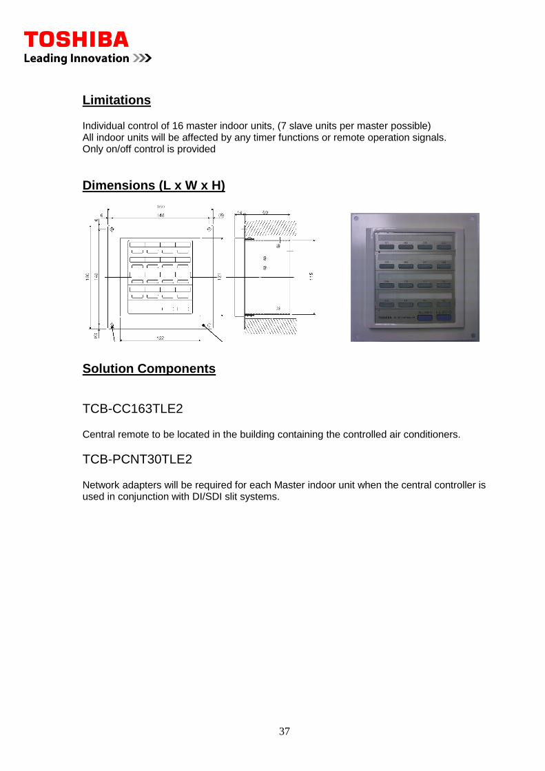
Limitations Individual control of 16 master indoor units, (7 slave units per master possible) All indoor units will be affected by any timer functions or remote operation signals. Only on/off control is provided
Dimensions (L x W x H)
Solution Components
TCB-CC163TLE2 Central remote to be located in the building containing the controlled air conditioners.
TCB-PCNT30TLE2 Network adapters will be required for each Master indoor unit when the central controller is used in conjunction with DI/SDI slit systems.
38
5.3 TCB-PCNT20TLE X&Y Protocol Converter
Description
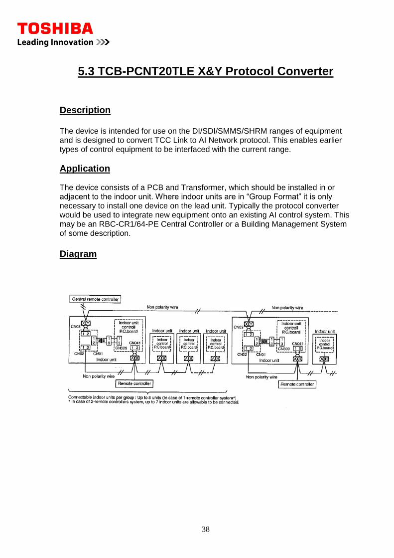
The device is intended for use on the DI/SDI/SMMS/SHRM ranges of equipment and is designed to convert TCC Link to AI Network protocol. This enables earlier types of control equipment to be interfaced with the current range.
Application The device consists of a PCB and Transformer, which should be installed in or adjacent to the indoor unit. Where indoor units are in “Group Format” it is only necessary to install one device on the lead unit. Typically the protocol converter would be used to integrate new equipment onto an existing AI control system. This may be an RBC-CR1/64-PE Central Controller or a Building Management System of some description.
Diagram
39
Connections Power for the primary side of the Transformer is obtained from the CN309 socket on the indoor PCB. A further connection is then made to the A & B terminals from CN02. Multiple devices would be connected together in a “daisy chain” fashion and each device given a unique address via dipswitches SW01.
Limitations It is recommended that 1.5mm2 2-core screened cable be used on all networks up to a maximum of 500Mtrs.
Addressing
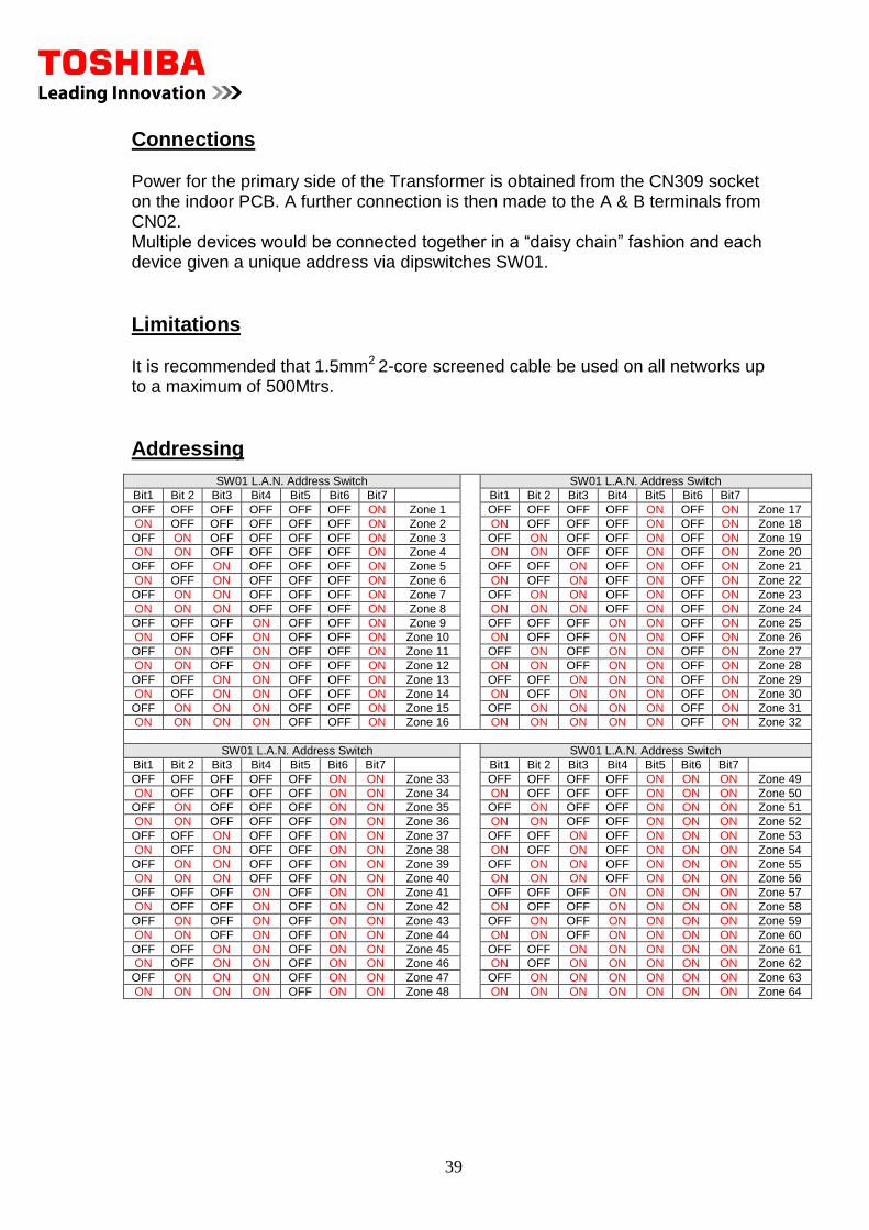
SW01 L.A.N. Address Switch
SW01 L.A.N. Address Switch
Bit1 Bit 2 Bit3 Bit4 Bit5 Bit6 Bit7 Bit1 Bit 2 Bit3 Bit4 Bit5 Bit6 Bit7
OFF OFF OFF OFF OFF OFF ON Zone 1 OFF OFF OFF OFF ON OFF ON Zone 17
ON OFF OFF OFF OFF OFF ON Zone 2 ON OFF OFF OFF ON OFF ON Zone 18
OFF ON OFF OFF OFF OFF ON Zone 3 OFF ON OFF OFF ON OFF ON Zone 19
ON ON OFF OFF OFF OFF ON Zone 4 ON ON OFF OFF ON OFF ON Zone 20
OFF OFF ON OFF OFF OFF ON Zone 5 OFF OFF ON OFF ON OFF ON Zone 21
ON OFF ON OFF OFF OFF ON Zone 6 ON OFF ON OFF ON OFF ON Zone 22
OFF ON ON OFF OFF OFF ON Zone 7 OFF ON ON OFF ON OFF ON Zone 23
ON ON ON OFF OFF OFF ON Zone 8 ON ON ON OFF ON OFF ON Zone 24
OFF OFF OFF ON OFF OFF ON Zone 9 OFF OFF OFF ON ON OFF ON Zone 25
ON OFF OFF ON OFF OFF ON Zone 10 ON OFF OFF ON ON OFF ON Zone 26
OFF ON OFF ON OFF OFF ON Zone 11 OFF ON OFF ON ON OFF ON Zone 27
ON ON OFF ON OFF OFF ON Zone 12 ON ON OFF ON ON OFF ON Zone 28
OFF OFF ON ON OFF OFF ON Zone 13 OFF OFF ON ON ON OFF ON Zone 29
ON OFF ON ON OFF OFF ON Zone 14 ON OFF ON ON ON OFF ON Zone 30
OFF ON ON ON OFF OFF ON Zone 15 OFF ON ON ON ON OFF ON Zone 31
ON ON ON ON OFF OFF ON Zone 16 ON ON ON ON ON OFF ON Zone 32
SW01 L.A.N. Address Switch
SW01 L.A.N. Address Switch
Bit1 Bit 2 Bit3 Bit4 Bit5 Bit6 Bit7 Bit1 Bit 2 Bit3 Bit4 Bit5 Bit6 Bit7
OFF OFF OFF OFF OFF ON ON Zone 33 OFF OFF OFF OFF ON ON ON Zone 49
ON OFF OFF OFF OFF ON ON Zone 34 ON OFF OFF OFF ON ON ON Zone 50
OFF ON OFF OFF OFF ON ON Zone 35 OFF ON OFF OFF ON ON ON Zone 51
ON ON OFF OFF OFF ON ON Zone 36 ON ON OFF OFF ON ON ON Zone 52
OFF OFF ON OFF OFF ON ON Zone 37 OFF OFF ON OFF ON ON ON Zone 53
ON OFF ON OFF OFF ON ON Zone 38 ON OFF ON OFF ON ON ON Zone 54
OFF ON ON OFF OFF ON ON Zone 39 OFF ON ON OFF ON ON ON Zone 55
ON ON ON OFF OFF ON ON Zone 40 ON ON ON OFF ON ON ON Zone 56
OFF OFF OFF ON OFF ON ON Zone 41 OFF OFF OFF ON ON ON ON Zone 57
ON OFF OFF ON OFF ON ON Zone 42 ON OFF OFF ON ON ON ON Zone 58
OFF ON OFF ON OFF ON ON Zone 43 OFF ON OFF ON ON ON ON Zone 59
ON ON OFF ON OFF ON ON Zone 44 ON ON OFF ON ON ON ON Zone 60
OFF OFF ON ON OFF ON ON Zone 45 OFF OFF ON ON ON ON ON Zone 61
ON OFF ON ON OFF ON ON Zone 46 ON OFF ON ON ON ON ON Zone 62
OFF ON ON ON OFF ON ON Zone 47 OFF ON ON ON ON ON ON Zone 63
ON ON ON ON OFF ON ON Zone 48 ON ON ON ON ON ON ON Zone 64
40
5.4 TCB-PCNT30TLE TCC Link Network Adaptor
Description
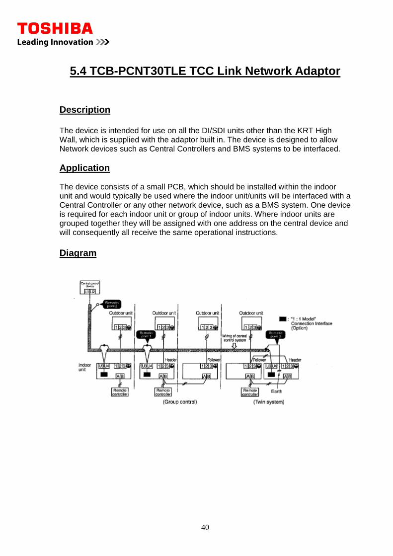
The device is intended for use on all the DI/SDI units other than the KRT High Wall, which is supplied with the adaptor built in. The device is designed to allow Network devices such as Central Controllers and BMS systems to be interfaced.
Application The device consists of a small PCB, which should be installed within the indoor unit and would typically be used where the indoor unit/units will be interfaced with a Central Controller or any other network device, such as a BMS system. One device is required for each indoor unit or group of indoor units. Where indoor units are grouped together they will be assigned with one address on the central device and will consequently all receive the same operational instructions.
Diagram
41
Connections The device connects to the indoor unit PCB via socket CN50 and will provide two terminal network connection designated U3 & U4. Where multiple devices are to be installed it is necessary to set one unit with a 100ohm termination resistance. This would normally be on the device connected to the unit with the lowest network address. The resistance being set by SW01 bit being set to ON. When the device/devices have been installed and a termination resistance applied it is then necessary to apply a unique network and refrigerant line address to each unit.
Addressing Procedure The address setting is carried from a standard RBC-AMT21/31E remote controller. Where units do not have standard remote controllers installed, one should be temporarily attached in order to carry out the configuration process. Accessing the Engineers configuration menu Press Set CL & Check Simultaneously for 4 seconds. Navigate to menu item 12 (refrigerant line address) using the Temperature Set Buttons. Set a unique line address using the Timer Set Buttons and then press SET. Navigate to menu item 03 (network address) using the Temperature Set Buttons. Set a unique network address using the Temperature Set Buttons and then press SET Press the CHECK button to complete the setting process Generally speaking the refrigerant line address would mirror the network address, however this would not be the case with grouped units, which would have the same network address but different line addresses.
Limitations It is recommended that 1.5mm2 2-core screened cable be used on all networks up to a maximum of 500Mtrs in length. The KRT range of units do not require adaptors as they are supplied with U3 & U4 connections and also have a termination resistance facility on the indoor PCB. The termination resistance being set by SW01 bit 1 being set to ON.
42
6.1 RBC-WP1-PE Windows Control Package
Description The RBC-WP1-PE is a front-end software package that controls all aspects of the air conditioning systems installed on a site. The software is installed on a PC, which then connects to a TCB-IFLN640TLE2 LonWorks gateway for connection to the indoor units. The software allows all of the units operating parameters to be adjusted from the one PC. It allows faults to be reported and re-transmitted via email, fax or text message. The software can be accessed remotely either by telephone or via the Internet. The software can log data and provide graphical representation of data. It has a schedule built-in for time control and it can also be used to reset set points or modes of operation. When the software is installed, it will automatically install the gateways and power meters and it will then generate basic graphics.
Application The software is used when a computer solution is required in order to provide a flexible solution to allow the air conditioning to be fully controlled from one central point. It offers much functionality, which is suited to small and large systems.
Features of the Software Customization
The software being very flexible, it allows for a fully adaptable graphical representation of the building to be included.
Frost Protection The software has the ability to sample the air temperature from an individual or a selection of indoor units. Then, based on this data, operate the air conditioning to give frost and fabric protection to the building
Energy monitoring The energy monitoring software can be included to calculate the running costs of the individual indoor units. This data can then be provided in structured bills for the building tenants. This data is calculated from the demand given from the indoor units and the power consumed by the system. The RBC-EM1-PE power meter is required for this function. This option is covered in a separate data sheet.
43
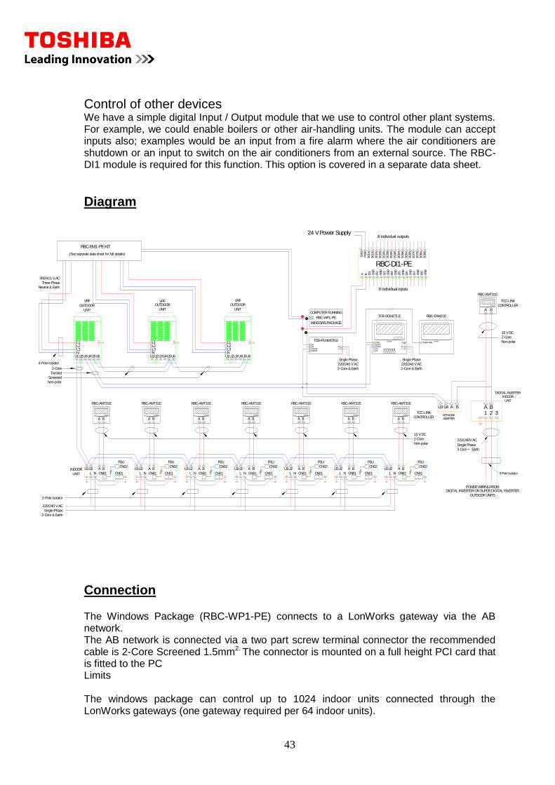
Control of other devices We have a simple digital Input / Output module that we use to control other plant systems. For example, we could enable boilers or other air-handling units. The module can accept inputs also; examples would be an input from a fire alarm where the air conditioners are shutdown or an input to switch on the air conditioners from an external source. The RBC-DI1 module is required for this function. This option is covered in a separate data sheet.
Diagram
Connection The Windows Package (RBC-WP1-PE) connects to a LonWorks gateway via the AB network. The AB network is connected via a two part screw terminal connector the recommended cable is 2-Core Screened 1.5mm2. The connector is mounted on a full height PCI card that is fitted to the PC Limits The windows package can control up to 1024 indoor units connected through the LonWorks gateways (one gateway required per 64 indoor units).
INDOOR A B
L N
U1U2
2-Core & Earth
Single-Phase
220/240 V AC
2-Pole Isolator
2-Core
CN01
CN02
CN81
FSU
U2U1
NL
BA A B
L N
U1U2 A BL N
U1U2 U2U1
NL
BA U2U1
NL
BA
TOSHIBA
CN02U1/U3U2/U4C3C4 A
1A2
A3
B1
B2
B3
NL
E TIMER TMNLTOSHIBA
RBC-EXW21ETCB-SC642TLE
220/240 V AC
Single Phase
2-Core & Earth
RBC-AMT31E
Screened
Twisted
Non-polar
Neutral & Earth
380/415 V AC
Three-Phase
RBC-AMT31ERBC-AMT31ERBC-AMT31ERBC-AMT31ERBC-AMT31E RBC-AMT31E
A B
L N
U1U2
Non-polar
CONTROLLER
TCC-LINK
2-Core
15 V DC
UNIT
U2U1 U3U4 U6U5
L1L2L3N
UNIT
OUTDOOR
4-Pole Isolator
OUTDOOR
UNIT
NL3L2L1
U5U6U4U3U1U2 U2U1 U3U4 U6U5
L1L2L3N
UNIT
OUTDOOR
FSU
CN02
CN01CN81
FSU
CN02
CN01CN81
FSU
CN02
CN01CN81
FSU
CN02
CN01CN81
FSU
CN02
CN01CN81
FSU
CN02
CN01CN81
RBC-WP1-PE
COMPUTER RUNNING
WINDOWS PACKAGE
LN
2-Core & Earth
Single Phase
220/240 V AC
U2/U4U1/U3
TCB-IFLN640TLE
BA
AB
3 Pole Isolator
31 2A B
ADAPTER
B
NETWORK
U4U3 A
INDOORUNIT
RBC-AMT31E
TOSHIBA
A B
Non-polar
2-Core
15 V DC
CONTROLLER
TCC-LINK
3 Core + Earth
220/240V AC
Single Phase
RBC-EM1-PE KIT
(See seperate data sheet for full details)
VRFVRF VRF
DIGITAL INVERTER
POWER WIRING FROMDIGITAL INVERTER OR SUPER DIGITAL INVERTER
OUTDOOR UNITS
DI8
RBC-DI1-PE
DI2
DI1
A B GN
D
DI5
GN
D
DI3
GN
D
GN
D
DI4
GN
D
DI6
GN
D
GN
D
DI7
DO
2B
DO
1A
GN
D
PW
R
DO
1B
DO
2A
DO
5B
DO
4A
DO
3A
DO
3B
DO
4B
DO
5A
DO
7A
DO
6A
DO
6B
DO
7B
DO
8A
GN
DD
O8B
24 V Power Supply8 individual outputs
8 individual inputs
44
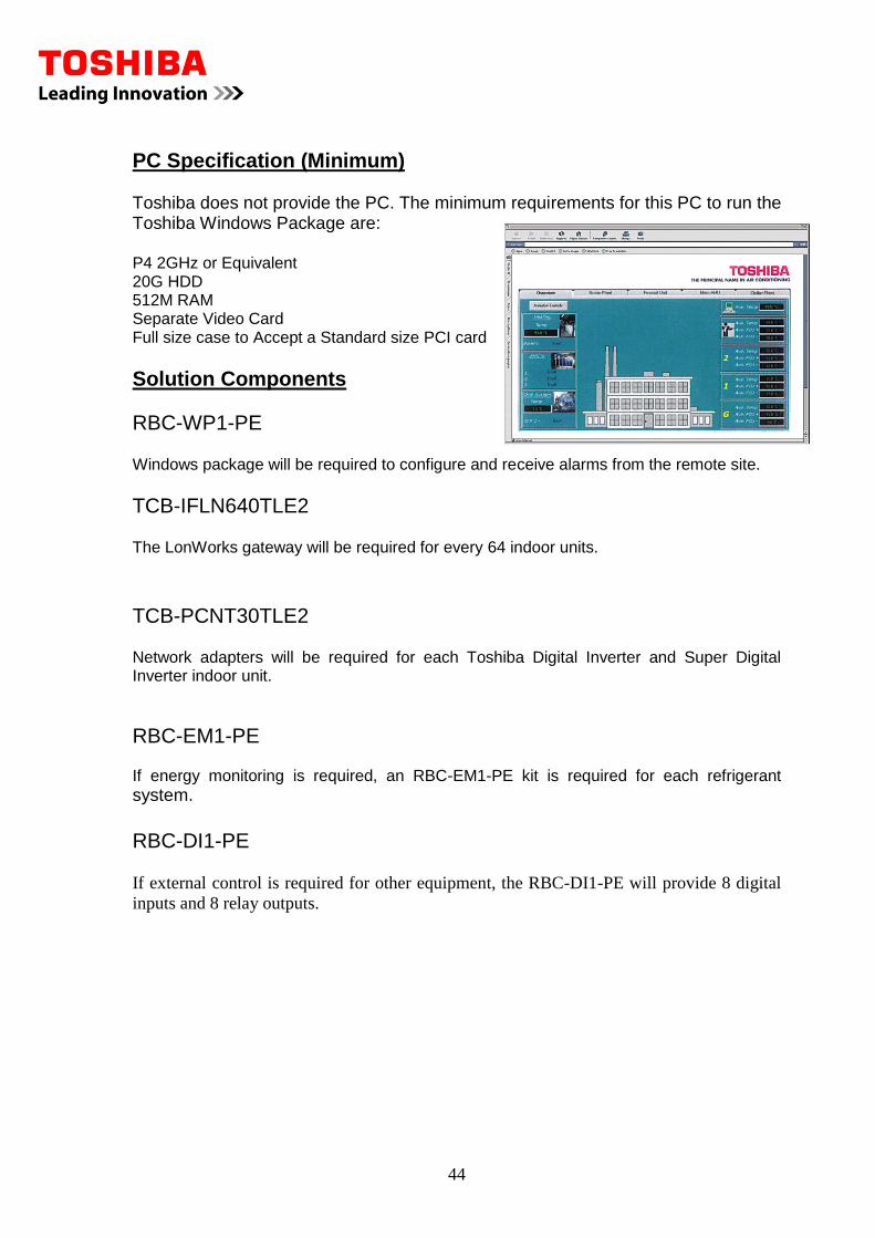
PC Specification (Minimum) Toshiba does not provide the PC. The minimum requirements for this PC to run the Toshiba Windows Package are: P4 2GHz or Equivalent 20G HDD 512M RAM Separate Video Card Full size case to Accept a Standard size PCI card
Solution Components
RBC-WP1-PE Windows package will be required to configure and receive alarms from the remote site.
TCB-IFLN640TLE2 The LonWorks gateway will be required for every 64 indoor units. TCB-PCNT30TLE2 Network adapters will be required for each Toshiba Digital Inverter and Super Digital Inverter indoor unit.
RBC-EM1-PE If energy monitoring is required, an RBC-EM1-PE kit is required for each refrigerant system.
RBC-DI1-PE If external control is required for other equipment, the RBC-DI1-PE will provide 8 digital
inputs and 8 relay outputs.
45
6.2 RBC-EM1-PE Windows Energy Monitoring
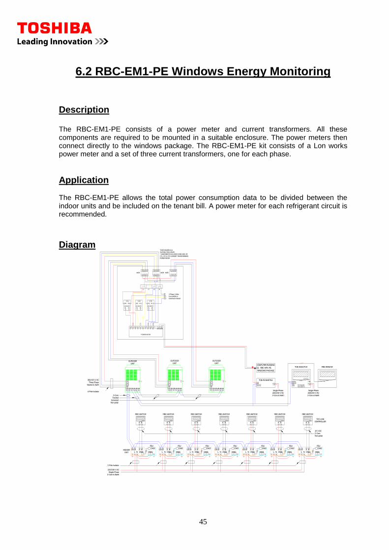
Description The RBC-EM1-PE consists of a power meter and current transformers. All these components are required to be mounted in a suitable enclosure. The power meters then connect directly to the windows package. The RBC-EM1-PE kit consists of a Lon works power meter and a set of three current transformers, one for each phase.
Application The RBC-EM1-PE allows the total power consumption data to be divided between the indoor units and be included on the tenant bill. A power meter for each refrigerant circuit is recommended.
Diagram
INDOOR A B
L N
U1U2
2-Core & Earth
Single-Phase
220/240 V AC
2-Pole Isolator
2-Core
CN01
CN02
CN81
FSU
U2U1
NL
BA A B
L N
U1U2 A BL N
U1U2 U2U1
NL
BA U2U1
NL
BA
TOSHIBA
CN02U1/U3U2/U4C3C4 A
1A
2A
3B1
B2
B3
NL
E TIMER TMNLTOSHIBA
RBC-EXW21ETCB-SC642TLE
220/240 V AC
Single Phase
2-Core & Earth
RBC-AMT21E
Screened
Twisted
Non-polar
Neutral & Earth
380/415 V AC
Three-Phase
RBC-AMT21ERBC-AMT21ERBC-AMT21ERBC-AMT21ERBC-AMT21E RBC-AMT21E
A B
L N
U1U2
Non-polar
CONTROLLER
TCC-LINK
2-Core
15 V DC
UNIT
U2U1 U3U4 U6U5
L1L2L3N
UNIT
OUTDOOR
4-Pole Isolator
OUTDOOR
UNIT
NL3L2L1
U5U6U4U3U1U2 U2U1 U3U4 U6U5
L1L2L3N
UNIT
OUTDOOR
FSU
CN02
CN01CN81
FSU
CN02
CN01CN81
FSU
CN02
CN01CN81
FSU
CN02
CN01CN81
FSU
CN02
CN01CN81
FSU
CN02
CN01CN81
RBC-WP1-PE
COMPUTER RUNNING
WINDOWS PACKAGE
LN
2-Core & Earth
Single Phase
220/240 V AC
U2/U4U1/U3
TCB-IFLN640TLE
BA
AB
L1 L3L2 N
L1 NL2L3 L1
L1
N
N
L3L2
L2L3
L1 L2 L3 N
P2
*CT3
SECONDARY
P1
S1 S2
SECONDARY
S1
P2 P1
S2
*CT2*CT1
SECONDARY
P2
S1
P1
S2
1 2 3 4 5 6 7 8 9 11
*POWER METER
Distribution Board
from MCB's in
3 Phase 4-Wire
MCBMCB
L2L1
L3
24/B 23/A
N
*COMPONENTS INCLUDED IN RBC-EM1-PE:
SUITABLE ENCLOSURE
TO BE HOUSED IN A
CT1, CT2 & CT3 CURRENT TRANSFORMERS;
POWER METER
L1 L3L2 N
L1 NL2L3MCB
46
Connections The power meter connects to the PC and LonWorks gateway via the AB network the recommended cable is 2-Core Screened 1.5mm2. The current transformers connect to the power meter by a 1.5mm2 cable The power meter requires a reference voltage from each phase the power meter should be protected by a circuit breaker. The supply to the outdoor unit should pass through the centre of the current transformer.
Limits
One power meter for each refrigerant circuit, i.e. one RBC-EM1-PE is required per system.
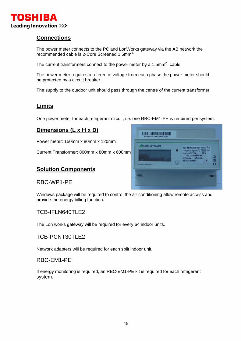
Dimensions (L x H x D) Power meter: 150mm x 80mm x 120mm Current Transformer: 800mm x 80mm x 600mm
Solution Components RBC-WP1-PE Windows package will be required to control the air conditioning allow remote access and provide the energy billing function.
TCB-IFLN640TLE2 The Lon works gateway will be required for every 64 indoor units.
TCB-PCNT30TLE2 Network adapters will be required for each split indoor unit.
RBC-EM1-PE If energy monitoring is required, an RBC-EM1-PE kit is required for each refrigerant system.
47
6.3 RBC-DI1 Windows Control and Other Equipment
Description
The RBC-DI1 is a module that connects to the LonWorks network that links back to the Interactive Intelligence software running on a PC in the building. The module has 8 digital inputs and eight relay outputs. These inputs can be used to control external plant or except inputs from other plant.
Application The application of this module is very versatile as it is an interface to other equipment. If an input is made to the module Interactive intelligence can act on the input and perform an operation i.e. enable units in specific modes, indicate status of external plant on the PC etc. The relay outputs can be used to enable external plant in conjunction with the AC or independently.
Examples of use for the Inputs Fire Alarm Shutdown Extend unit operation for a fixed time Hotel key card unit set back Examples of use for the Outputs Enable air handling plant Toshiba VN unit control Lighting control Fault Output
48
Diagram
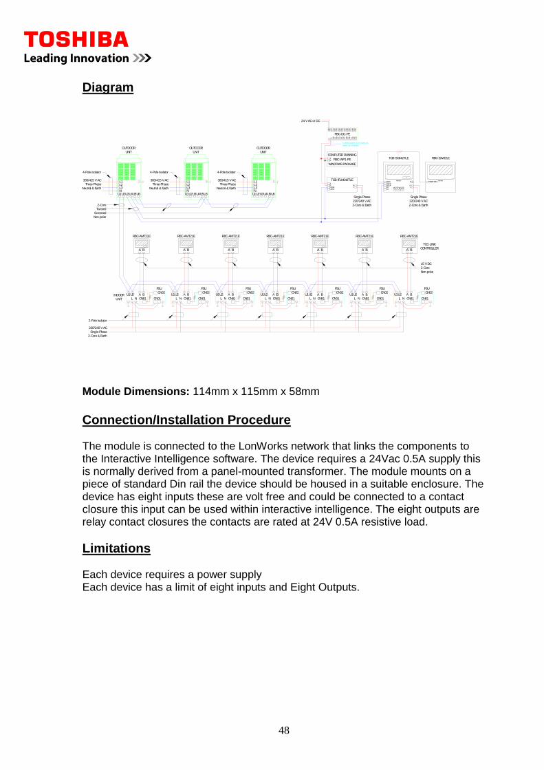
Module Dimensions: 114mm x 115mm x 58mm
Connection/Installation Procedure The module is connected to the LonWorks network that links the components to the Interactive Intelligence software. The device requires a 24Vac 0.5A supply this is normally derived from a panel-mounted transformer. The module mounts on a piece of standard Din rail the device should be housed in a suitable enclosure. The device has eight inputs these are volt free and could be connected to a contact closure this input can be used within interactive intelligence. The eight outputs are relay contact closures the contacts are rated at 24V 0.5A resistive load.
Limitations Each device requires a power supply Each device has a limit of eight inputs and Eight Outputs.
INDOOR A B
L N
U1U2
2-Core & Earth
Single-Phase
220/240 V AC
2-Pole Isolator
2-Core
CN01
CN02
CN81
FSU
U2U1
NL
BA A B
L N
U1U2 A BL N
U1U2 U2U1
NL
BA U2U1
NL
BA
TOSHIBA
CN02U1/U3U2/U4C3C4 A
1A2
A3
B1
B2
B3
NL
E TIMER TMNLTOSHIBA
RBC-EXW21ETCB-SC642TLE
220/240 V AC
Single Phase
2-Core & Earth
RBC-AMT21E
Screened
Twisted
Non-polar
Neutral & Earth
380/415 V AC
Three-Phase
RBC-AMT21ERBC-AMT21ERBC-AMT21ERBC-AMT21ERBC-AMT21E RBC-AMT21E
A B
L N
U1U2
Non-polar
CONTROLLER
TCC-LINK
2-Core
15 V DC
UNIT
U2U1 U3U4 U6U5
L1L2L3N
UNIT
OUTDOOR
4-Pole Isolator 4-Pole Isolator
OUTDOOR
UNIT
NL3L2L1
U5U6U4U3U1U2
Three-Phase
380/415 V AC
Neutral & Earth Neutral & Earth
380/415 V AC
Three-Phase
U2U1 U3U4 U6U5
L1L2L3N
UNIT
OUTDOOR
4-Pole Isolator
FSU
CN02
CN01CN81
FSU
CN02
CN01CN81
FSU
CN02
CN01CN81
FSU
CN02
CN01CN81
FSU
CN02
CN01CN81
FSU
CN02
CN01CN81
TOSHIBA
A BTOSHIBA
A BTOSHIBA
A BTOSHIBA
A BTOSHIBA
A BTOSHIBA
A BTOSHIBA
A B
RBC-WP1-PE
COMPUTER RUNNING
WINDOWS PACKAGE
LN
2-Core & Earth
Single Phase
220/240 V AC
U2/U4U1/U3
TCB-IFLN640TLE
BA
AB
DI8
RBC-DI1-PE
DI2
DI1
A B GN
D
DI5
GN
D
DI3
GN
D
GN
D
DI4
GN
D
DI6
GN
D
GN
D
DI7
DO
2B
DO
1A
GN
D
PW
R
DO
1B
DO
2A
DO
5B
DO
4A
DO
3A
DO
3B
DO
4B
DO
5A
DO
7A
DO
6A
DO
6B
DO
7B
DO
8A
GN
DD
O8B
24 V AC or DC
TO FIRE ALARM SHUT DOWN VIA
PANEL (BY OTHERS).
49
7.1 Touch Screen Controller
Description
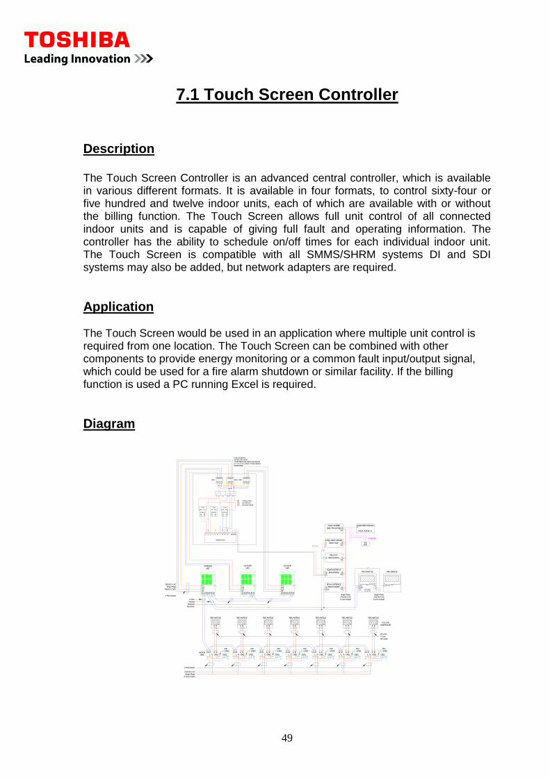
The Touch Screen Controller is an advanced central controller, which is available in various different formats. It is available in four formats, to control sixty-four or five hundred and twelve indoor units, each of which are available with or without the billing function. The Touch Screen allows full unit control of all connected indoor units and is capable of giving full fault and operating information. The controller has the ability to schedule on/off times for each individual indoor unit. The Touch Screen is compatible with all SMMS/SHRM systems DI and SDI systems may also be added, but network adapters are required.
Application The Touch Screen would be used in an application where multiple unit control is required from one location. The Touch Screen can be combined with other components to provide energy monitoring or a common fault input/output signal, which could be used for a fire alarm shutdown or similar facility. If the billing function is used a PC running Excel is required.
Diagram
INDOOR A B
L N
U1U2
2-Core & Earth
Single-Phase
220/240 V AC
2-Pole Isolator
2-Core
CN01
CN02
CN81
FSU
U2U1
NL
BA A B
L N
U1U2 A BL N
U1U2 U2U1
NL
BA U2U1
NL
BA
TOSHIBA
CN02U1/U3U2/U4C3C4 A
1A2
A3
B1
B2
B3
NL
E TIMER TMNLTOSHIBA
RBC-EXW21ETCB-SC642TLE
220/240 V AC
Single Phase
2-Core & Earth
RBC-AMT21E
Screened
Twisted
Non-polar
Neutral & Earth
380/415 V AC
Three-Phase
RBC-AMT21ERBC-AMT21ERBC-AMT21ERBC-AMT21ERBC-AMT21E RBC-AMT21E
A B
L N
U1U2
Non-polar
CONTROLLER
TCC-LINK
2-Core
15 V DC
UNIT
U2U1 U3U4 U6U5
L1L2L3N
UNIT
OUTDOOR
4-Pole Isolator
OUTDOOR
UNIT
NL3L2L1
U5U6U4U3U1U2 U2U1 U3U4 U6U5
L1L2L3N
UNIT
OUTDOOR
FSU
CN02
CN01CN81
FSU
CN02
CN01CN81
FSU
CN02
CN01CN81
FSU
CN02
CN01CN81
FSU
CN02
CN01CN81
FSU
CN02
CN01CN81
BMS-IFWH3E
POWER METER I/F
2-Core & Earth
Single Phase
220/240 V AC
U2/U4U1/U3
RELAY INTERFACE
L1 L3L2 N
L1 NL2L3 L1
L1
N
N
L3L2
L2L3
L1 L2 L3 N
P2
*CT3
SECONDARY
P1
S1 S2
SECONDARY
S1
P2 P1
S2
*CT2*CT1
SECONDARY
P2
S1
P1
S2
1 2 3 4 5 6 7 8 9 11
*POWER METER
Distribution Board
from MCB's in
3 Phase 4-Wire
MCBMCB
L2L1
L3
24/B 23/A
N
*COMPONENTS INCLUDED IN RBC-EM1-PE:
SUITABLE ENCLOSURE
TO BE HOUSED IN A
CT1, CT2 & CT3 CURRENT TRANSFORMERS;
POWER METER
L1 L3L2 N
L1 NL2L3MCB
BMS-IFDD01E
RELAY I/F
BMS-LSV4E
INTELLIGENT SERVER
BMS-TP5120TWE
TOUCH SCREEN COMPUTER RUNNING
EXCEL FOR BILLS
BMS-IFLSV2E2
HUB
ETHERNET
RS-485
LN
LN
LN
LN
LN
E
AB
BA
AB
AB
E
E
E
E
50
Connection/Installation Procedure The Touch Screen connects to an RS485 Network, which links the screen to the Relay Interfaces. The Relay Interfaces are then connected to the Air Conditioning Network via the U3 & U4 connection. The RS485 Network also connects to the power meter and digital input/out interfaces. If the energy monitoring facility is being used a separate PC will be required to run the energy monitoring software. This PC will require Microsoft Excel and will need to be connected to the Touch Screen via a network connection. The Touch Screen requires a 240V 3A mains power supply Additional Components TCS Net Relay Interface BMS-IFLSV2E2 The Relay Interface connects to the Touch Screen Controller via the RS485 Network using connections A & B. The air conditioning network connects to terminals U1 & U2 (U3 & U4 at the outdoor unit) and a maximum of 64 Indoor units may be served. The relay interface requires a 240V 3 A mains power supply. Energy Monitoring Relay Interface BMS-IFWH4E2 The energy monitoring Relay Interface connects to the RS485 Network and provides a means of interface to the pulse power meters. Up to eight power meters can be connected to each Relay Interface. Digital Input Output Relay Interface BMS-IFDD02E2 The D/I module connects to the RS485 network and provides 8 inputs and 4 outputs, which could be used to interface a fire alarm system or a room occupancy sensor. The D/I module output could be used as a means of remote fault indication to another system. Software Site-specific software is written for the Touch Screen, which gives specific names and locations for easy end-user operation. The software also configures the D/I module and the Energy Monitoring Interfaces. Energy monitoring software is installed on a separate PC. The software being Excel based and using Macros to produce the reports for each Tenant.
51
Limitations The total length of the U1/U2 network for each relay interface is as follows 1.5mm2 Screened up to 1000m 2.5mm2 Screened up to 2000m The total length of the RS485 Network A/B 1.5mm2 Screened up to 500m
Components Touch Screens BMS-TP0641ACE Touch screen for 64 indoor units BMS-TP0641PWE Touch screen for 64 indoor units with energy billing BMS-TP5121ACE Touch screen for 512 indoor units BMS-TP5121PWE Touch screen for 512 indoor units with energy billing Interface Components BMS-IFLSV2E2 TCS Net Relay Interface BMS-IFWH4E2 Energy Monitoring Relay Interface BMS-IFDD02E2 Digital Input Output Relay Interface
52
8.1 TCB-IFLN642TLE LonWorks Interface
Description
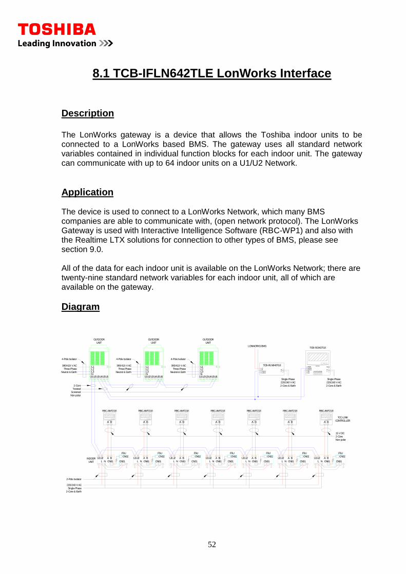
The LonWorks gateway is a device that allows the Toshiba indoor units to be connected to a LonWorks based BMS. The gateway uses all standard network variables contained in individual function blocks for each indoor unit. The gateway can communicate with up to 64 indoor units on a U1/U2 Network.
Application The device is used to connect to a LonWorks Network, which many BMS companies are able to communicate with, (open network protocol). The LonWorks Gateway is used with Interactive Intelligence Software (RBC-WP1) and also with the Realtime LTX solutions for connection to other types of BMS, please see section 9.0. All of the data for each indoor unit is available on the LonWorks Network; there are twenty-nine standard network variables for each indoor unit, all of which are available on the gateway.
Diagram
U1U2
2-Core & Earth
Single-Phase
220/240 V AC
2-Pole Isolator
2-Core
CN01
CN02
CN81
FSU
U2U1
NL
BA A B
L N
U1U2 A BL
INDOOR A B
L N N
U1U2 U2U1
NL
BA U2U1
NL
BA
TOSHIBA
CN02U1/U3U2/U4C3C4 A
1A2
A3
B1
B2
B3
NL
E
TCB-SC642TLE
220/240 V AC
Single Phase
2-Core & Earth
RBC-AMT21E
Screened
Twisted
Non-polar
Neutral & Earth
380/415 V AC
Three-Phase
RBC-AMT21ERBC-AMT21ERBC-AMT21ERBC-AMT21ERBC-AMT21E RBC-AMT21E
A B
L N
U1U2
Non-polar
CONTROLLER
TCC-LINK
2-Core
15 V DC
UNIT
U2U1 U3U4 U6U5
L1L2L3N
UNIT
OUTDOOR
4-Pole Isolator 4-Pole Isolator
OUTDOOR
UNIT
NL3L2L1
U5U6U4U3U1U2
Three-Phase
380/415 V AC
Neutral & Earth Neutral & Earth
380/415 V AC
Three-Phase
U2U1 U3U4 U6U5
L1L2L3N
UNIT
OUTDOOR
4-Pole Isolator
FSU
CN02
CN01CN81
FSU
CN02
CN01CN81
FSU
CN02
CN01CN81
FSU
CN02
CN01CN81
FSU
CN02
CN01CN81
FSU
CN02
CN01CN81
TOSHIBA
A BTOSHIBA
A BTOSHIBA
A BTOSHIBA
A BTOSHIBA
A BTOSHIBA
A BTOSHIBA
A B
LN
2-Core & Earth
Single Phase
220/240 V AC
U2/U4U1/U3
TCB-IFLN640TLE
BA
LONWORKS BMS
53
Connection/Installation Procedure The gateway connects to the air conditioner network via U1 & U2 and the LonWorks network connects via the A & B connection. A 240V 3A mains supply is required for the gateway.
Limitations The total length of the air conditioner U1/U2 network for each relay interface is as follows. 1.5mm2 Screened up to 1000m 2.5mm2 Screened up to 2000m The LonWorks network should be 1.5mm2 Screened up to 500m
54
9.1 BACnet®
Interface
Description
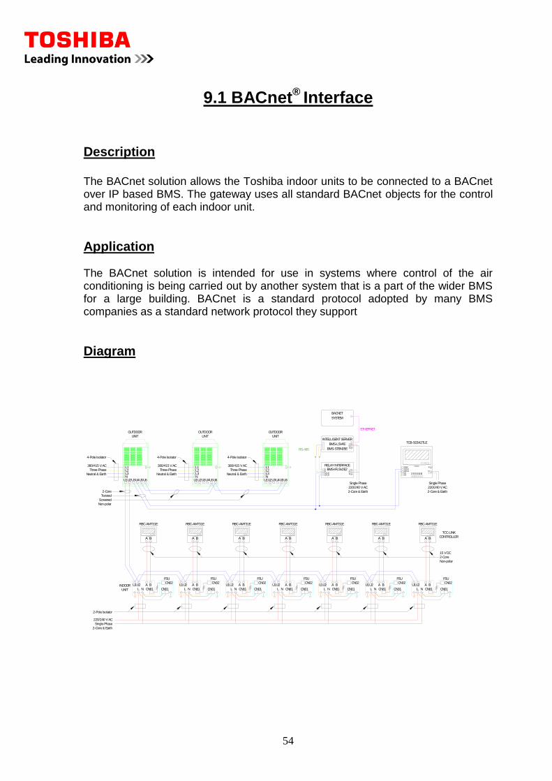
The BACnet solution allows the Toshiba indoor units to be connected to a BACnet over IP based BMS. The gateway uses all standard BACnet objects for the control and monitoring of each indoor unit.
Application The BACnet solution is intended for use in systems where control of the air conditioning is being carried out by another system that is a part of the wider BMS for a large building. BACnet is a standard protocol adopted by many BMS companies as a standard network protocol they support
Diagram
U2U1 U3U4 U6U5
L1L2L3N
UNIT
OUTDOOR
4-Pole Isolator 4-Pole Isolator
OUTDOOR
UNIT
NL3L2L1
U5U6U4U3U1U2
Three-Phase
380/415 V AC
Neutral & Earth Neutral & Earth
380/415 V AC
Three-Phase
N
U1U2 U2U1
NL
BA U2U1
NL
BA
TOSHIBA
CN02U1/U3U2/U4C3C4 A
1A2
A3
B1
B2
B3
NL
E
TCB-SC642TLE
220/240 V AC
Single Phase
2-Core & Earth
Screened
Twisted
Non-polar
Neutral & Earth
380/415 V AC
Three-Phase
RBC-AMT31E
A B
L N
U1U2
Non-polar
CONTROLLER
TCC-LINK
2-Core
15 V DC
UNIT
INDOOR A B
L N
U1U2
2-Core & Earth
Single-Phase
220/240 V AC
2-Pole Isolator
2-Core
CN01
CN02
CN81
FSU
U2U1
NL
BA A B
L N
U1U2 A BL
U2U1 U3U4 U6U5
L1L2L3N
UNIT
OUTDOOR
4-Pole Isolator
FSU
CN02
CN01CN81
FSU
CN02
CN01CN81
FSU
CN02
CN01CN81
FSU
CN02
CN01CN81
FSU
CN02
CN01CN81
FSU
CN02
CN01CN81
TOSHIBA
A BTOSHIBA
A BTOSHIBA
A BTOSHIBA
A BTOSHIBA
A BTOSHIBA
A BTOSHIBA
A B
RBC-AMT31E RBC-AMT31E RBC-AMT31E RBC-AMT31E RBC-AMT31E RBC-AMT31E
2-Core & Earth
Single Phase
220/240 V AC
U2/U4U1/U3
RELAY INTERFACE
BMS-LSV4E
INTELLIGENT SERVER
BMS-IFLSV2E2
ETHERNET
RS-485
LN
LN
E
AB
E
BACNET
SYSTEM
BMS-STBN05E
55
Connection/Installation Procedure The BACnet solution consists of several different components, which have been listed below. The maximum number of indoor units that may be controlled is 128 per Intelligent Server. Up to a maximum of eight Relay Interfaces can be connected per Intelligent Server.
Intelligent Server BMS-LSV4E The intelligent server connects to the BACnet system by a network connection, usually to a local hub. The Relay Interfaces connect to the server by the RS485 network and up to eight Relay Interfaces may be connected, with a maximum of 128 indoor units. The Intelligent Server requires a 240V 3A mains supply.
BACnet Software BMS-STBN05E The BACnet software is contained on a standard Compact Flash Card, which plugs directly into the Intelligent Server. TCS Net Relay Interface BMS-IFLSV2E2 The Relay Interface connects to the Touch Screen Controller via the RS485 Network, (A & B connections). The air conditioner network connects to the U1 & U2 connections, with a maximum of 64 indoor units served. The Relay Interface requires a 240V 3 A mains supply.
Software Site-specific software is written for the BACnet solution and then uploaded to the Intelligent Server. This gives site-specific names and locations, which are then presented to the BACnet network. Limitations The total length of the air conditioner U1/U2 network for each relay interface is as follows. 1.5mm2 Screened up to 1000m 2.5mm2 Screened up to 2000m The total length of the RS485 Network A/B 1.5mm2 Screened up to 500m The total length of the Ethernet cable from the Hub to the server should be a maximum of 100M The IP Address range should not be used xx.xx.0.xx
56
10.1 Trend Solution (LTX-21)
Description The LTX-21 is a product that has been developed to enable Toshiba air conditioners to directly connect to a Trend BMS system. The LTX-21 connects directly to the Trend outstation supervisor port. The interface is capable of setting all of the operating parameters for each indoor unit. It also provides error codes and the return air temperatures.
Application
The LTX-21 solution is designed to allow connection to a Trend BMS system. It allows a fully functional solution to be achieved. The LTX-21 and associated Toshiba LonWorks gateway are usually mounted in the control panel with the outstation. We have two possible variations, which are outlined below.
LTX-21 and RBC-LG1 Combination
This uses a LTX-21 and an RBC-LG1-PE, which connects to a maximum of sixteen indoor units however; the TCB-PCNT20TLE network adapters are required to convert back to the AI network. This option will be cost effective for single split installations with less than 7 indoor units for all other situations use the solution below.
LTX-21, LTX-VCI and TCB-IFLN640TLE Combination
This solution uses an LTX-VCI and TCB-IFLN640TLE for the control of a maximum of 64 indoor units. The solution uses an LTX-21 for every 16 indoor units as these connect to the Trend outstations. For example, for a total of 64 indoor units you would use four LTX-21’s. In each of the above cases, multiples of the above combinations can be used to accommodate larger systems.
57
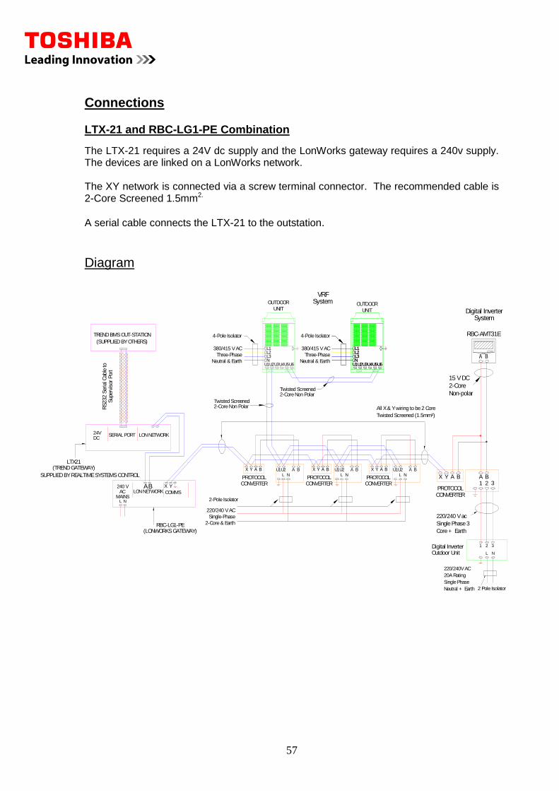
Connections LTX-21 and RBC-LG1-PE Combination
The LTX-21 requires a 24V dc supply and the LonWorks gateway requires a 240v supply. The devices are linked on a LonWorks network. The XY network is connected via a screw terminal connector. The recommended cable is 2-Core Screened 1.5mm2.
A serial cable connects the LTX-21 to the outstation.
Diagram
A B
L N
U1U2
2-Core & Earth
Single-Phase
220/240 V AC
2-Pole Isolator
U2U1
NL
BA A B
L N
U1U2
Neutral & Earth
380/415 V AC
Three-Phase
U2U1 U3U4 U6U5
L1L2L3N
UNIT
OUTDOOR
4-Pole Isolator
OUTDOOR
UNIT
NL3L2L1
U5U6U4U3U1U2
X A BY
PROTOCOLCONVERTER
NL3L2L1
U5U6U4U3U1U2
(LONWORKS GATEWAY)
SUPPLIED BY REALTIME SYSTEMS CONTROL
(TREND GATEWAY)LTX21
RBC-LG1-PE
TREND BMS OUT-STATION
(SUPPLIED BY OTHERS)
SERIAL PORT LON NETWORK
240 V
L NMAINS
AC COMMSAB YX
LON NETWORK
All X & Y wiring to be 2 Core
Twisted Screened (1.5mm²)
Y BAX X A BY
Twisted Screened2-Core Non Polar
Twisted Screened2-Core Non Polar
220/240 V ac
Single Phase 3
Core + Earth
15 V DC
2-Core
Non-polar
PROTOCOL
AX Y A BB21 3
RBC-AMT31E
CONVERTER
L
321
20A Rating
220/240V AC
Neutral + Earth
Single Phase
N
2 Pole Isolator
Outdoor UnitDigital Inverter
24VDC
RS232 S
eria
l Cab
le to
Super
viso
r Port
SystemDigital Inverter
SystemVRF
PROTOCOLCONVERTER
PROTOCOLCONVERTER
Neutral & Earth
380/415 V AC
Three-Phase
4-Pole Isolator
58
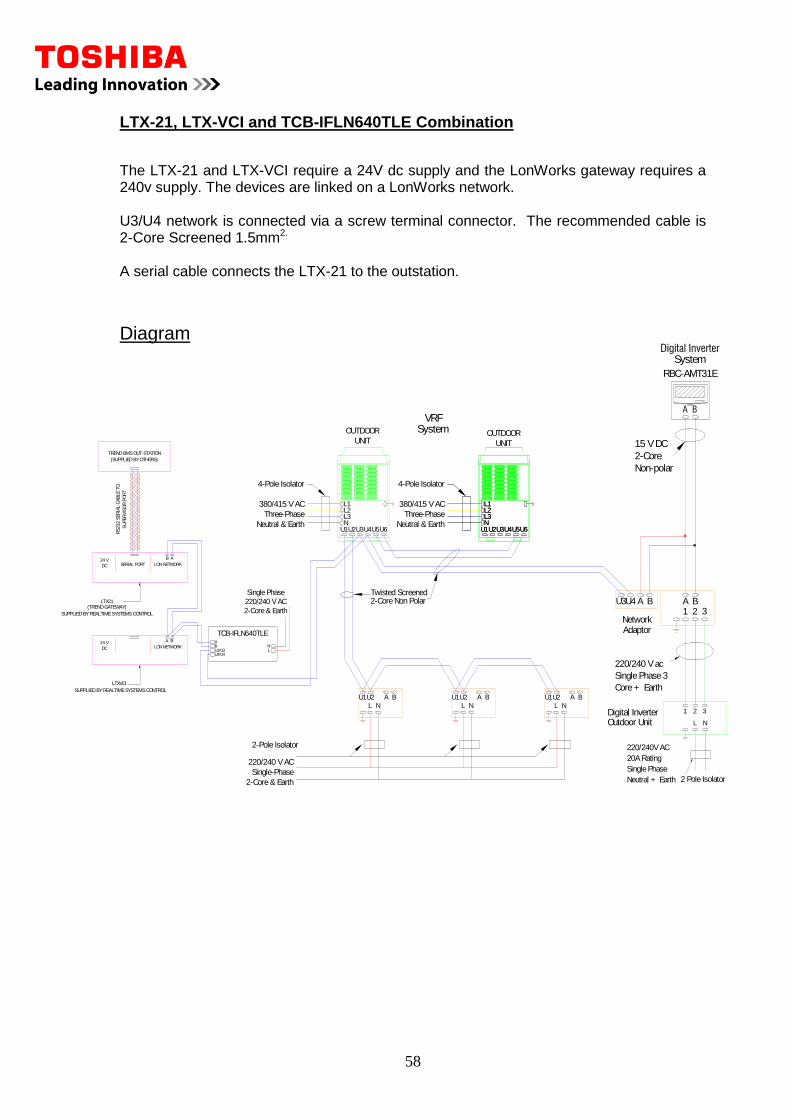
LTX-21, LTX-VCI and TCB-IFLN640TLE Combination The LTX-21 and LTX-VCI require a 24V dc supply and the LonWorks gateway requires a 240v supply. The devices are linked on a LonWorks network. U3/U4 network is connected via a screw terminal connector. The recommended cable is 2-Core Screened 1.5mm2. A serial cable connects the LTX-21 to the outstation.
Diagram
A B
L N
U1U2
2-Core & Earth
Single-Phase
220/240 V AC
2-Pole Isolator
U2U1
NL
BA A B
L N
U1U2
Neutral & Earth
380/415 V AC
Three-Phase
U2U1 U3U4 U6U5
L1L2L3N
UNIT
OUTDOOR
4-Pole Isolator
OUTDOOR
UNIT
NL3L2L1
U5U6U4U3U1U2NL3L2L1
U5U6U4U3U1U2
Twisted Screened2-Core Non Polar
220/240 V ac
Single Phase 3
Core + Earth
15 V DC
2-Core
Non-polar
Network
AU3U4 A BB21 3
RBC-AMT31E
Adaptor
L
321
20A Rating
220/240V AC
Neutral + Earth
Single Phase
N
2 Pole Isolator
Outdoor UnitDigital Inverter
System
SystemVRF
Neutral & Earth
380/415 V AC
Three-Phase
4-Pole Isolator
LN
2-Core & Earth
Single Phase
220/240 V AC
U2/U4U1/U3
TCB-IFLN640TLE
BA
LON NETWORKDC
24 VSERIAL PORT
TREND BMS OUT-STATION
(SUPPLIED BY OTHERS)
RS232 S
ER
IAL C
ABLE T
O
SU
PER
VIS
OR
PO
RT
LTX21(TREND GATEWAY)
SUPPLIED BY REALTIME SYSTEMS CONTROL
AB
BA
LON NETWORKDC
24 V
LTXVCI
SUPPLIED BY REALTIME SYSTEMS CONTROL
59
Limits LTX-21 and RBC-LG1-PE Combination This solution can control a maximum of sixteen indoor units and the TCB-PCNT20TLE network adapters are required for all indoor units.
LTX-21, LTX-VCI and TCB-IFLN640TLE Combination This solution can control a maximum of sixty-four indoor units with one LTX-21 for every sixteen indoor units.
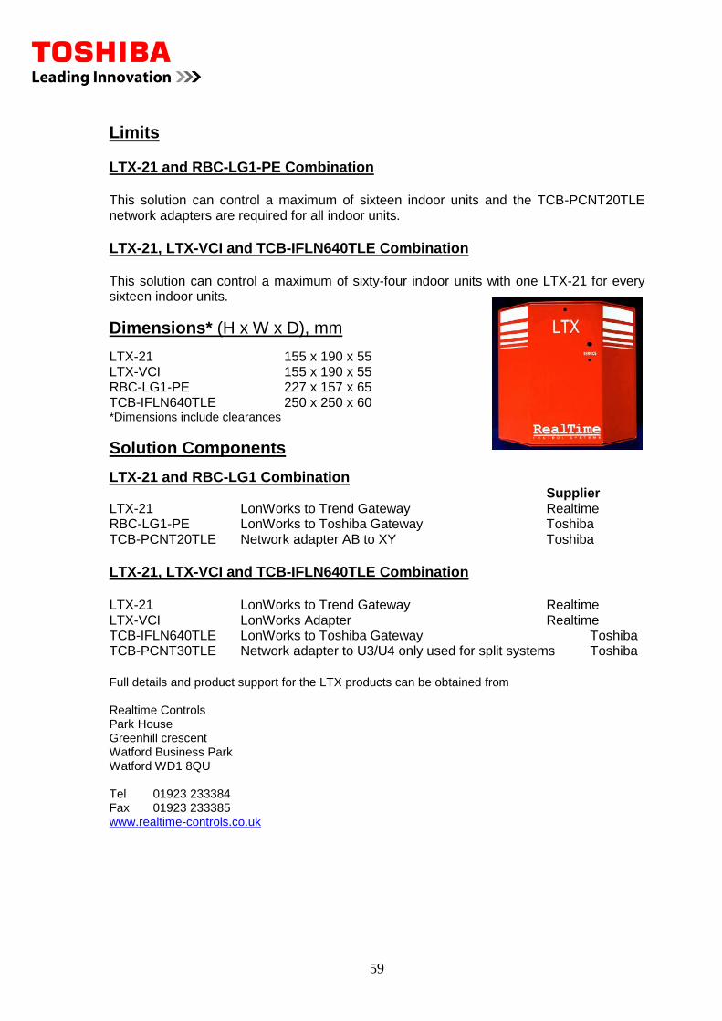
Dimensions* (H x W x D), mm
LTX-21 155 x 190 x 55 LTX-VCI 155 x 190 x 55 RBC-LG1-PE 227 x 157 x 65 TCB-IFLN640TLE 250 x 250 x 60 *Dimensions include clearances
Solution Components
LTX-21 and RBC-LG1 Combination Supplier LTX-21 LonWorks to Trend Gateway Realtime RBC-LG1-PE LonWorks to Toshiba Gateway Toshiba TCB-PCNT20TLE Network adapter AB to XY Toshiba
LTX-21, LTX-VCI and TCB-IFLN640TLE Combination LTX-21 LonWorks to Trend Gateway Realtime LTX-VCI LonWorks Adapter Realtime TCB-IFLN640TLE LonWorks to Toshiba Gateway Toshiba TCB-PCNT30TLE Network adapter to U3/U4 only used for split systems Toshiba
Full details and product support for the LTX products can be obtained from Realtime Controls Park House Greenhill crescent Watford Business Park Watford WD1 8QU Tel 01923 233384 Fax 01923 233385 www.realtime-controls.co.uk
60
10.2 Modbus Solution (LTX-51) Description The LTX-51 interface is a product that has been developed to enable Toshiba air conditioners to directly connect to a Modbus serial port on a BMS outstation. The interface is capable of setting all of the operating parameters for each indoor unit. It also provides error codes and the return air temperatures.
Application
The LTX-51 solution is designed to allow connection to a Trend BMS system. It allows a fully functional solution to be achieved. The LTX-51 and associated Toshiba LonWorks gateway are usually mounted in the control panel with the outstation. We have two possible variations, which are outlined below.
LTX-51 and RBC-LG1 Combination
This uses a LTX-51 and an RBC-LG1-PE, which connects to a maximum of sixteen indoor units; however, the TCB-PCNT20TLE network adapters are required to convert back to the AI network. This option will be cost effective for single split installations with less than 7 indoor units for all other situations use the solution below.
LTX-51, LTX-VCI and TCB-IFLN640TLE Combination
This solution uses an LTX-VCI and TCB-IFLN640TLE for the control of a maximum of 64 indoor units. The solution uses an LTX-51 for every 16 indoor units as these connect to the Trend outstations. For example, for a total of 64 indoor units you would use four LTX-51’s. In each of the above cases, multiples of the above combinations can be used to accommodate larger systems.
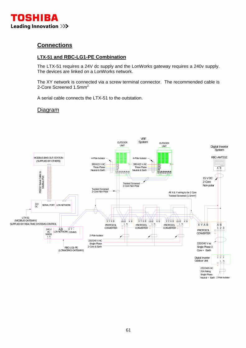
61
Connections LTX-51 and RBC-LG1-PE Combination
The LTX-51 requires a 24V dc supply and the LonWorks gateway requires a 240v supply. The devices are linked on a LonWorks network. The XY network is connected via a screw terminal connector. The recommended cable is 2-Core Screened 1.5mm2.
A serial cable connects the LTX-51 to the outstation.
Diagram
A B
L N
U1U2
2-Core & Earth
Single-Phase
220/240 V AC
2-Pole Isolator
U2U1
NL
BA A B
L N
U1U2
Neutral & Earth
380/415 V AC
Three-Phase
U2U1 U3U4 U6U5
L1L2L3N
UNIT
OUTDOOR
4-Pole Isolator
OUTDOOR
UNIT
NL3L2L1
U5U6U4U3U1U2
X A BY
PROTOCOLCONVERTER
NL3L2L1
U5U6U4U3U1U2
(LONWORKS GATEWAY)
SUPPLIED BY REALTIME SYSTEMS CONTROL
(MODBUS GATEWAY)LTX-51
RBC-LG1-PE
MODBUS BMS OUT-STATION
(SUPPLIED BY OTHERS)
SERIAL PORT LON NETWORK
240 V
L NMAINS
AC COMMSAB YX
LON NETWORK
All X & Y wiring to be 2 Core
Twisted Screened (1.5mm²)
Y BAX X A BY
Twisted Screened2-Core Non Polar
Twisted Screened2-Core Non Polar
220/240 V ac
Single Phase 3
Core + Earth
15 V DC
2-Core
Non-polar
PROTOCOL
AX Y A BB21 3
RBC-AMT31E
CONVERTER
L
321
20A Rating
220/240V AC
Neutral + Earth
Single Phase
N
2 Pole Isolator
Outdoor UnitDigital Inverter
24VDC
RS232 S
eria
l Cab
le to
Modbus
Port
SystemDigital Inverter
SystemVRF
PROTOCOLCONVERTER
PROTOCOLCONVERTER
Neutral & Earth
380/415 V AC
Three-Phase
4-Pole Isolator
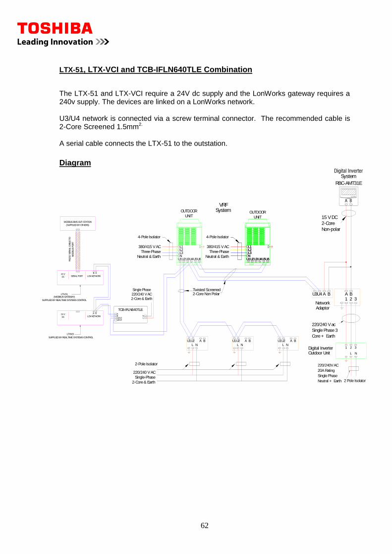
62
LTX-51, LTX-VCI and TCB-IFLN640TLE Combination The LTX-51 and LTX-VCI require a 24V dc supply and the LonWorks gateway requires a 240v supply. The devices are linked on a LonWorks network. U3/U4 network is connected via a screw terminal connector. The recommended cable is 2-Core Screened 1.5mm2. A serial cable connects the LTX-51 to the outstation.
Diagram
A B
L N
U1U2
2-Core & Earth
Single-Phase
220/240 V AC
2-Pole Isolator
U2U1
NL
BA A B
L N
U1U2
Neutral & Earth
380/415 V AC
Three-Phase
U2U1 U3U4 U6U5
L1L2L3N
UNIT
OUTDOOR
4-Pole Isolator
OUTDOOR
UNIT
NL3L2L1
U5U6U4U3U1U2NL3L2L1
U5U6U4U3U1U2
Twisted Screened2-Core Non Polar
220/240 V ac
Single Phase 3
Core + Earth
15 V DC
2-Core
Non-polar
Network
AU3U4 A BB21 3
RBC-AMT31E
Adaptor
L
321
20A Rating
220/240V AC
Neutral + Earth
Single Phase
N
2 Pole Isolator
Outdoor UnitDigital Inverter
System
SystemVRF
Neutral & Earth
380/415 V AC
Three-Phase
4-Pole Isolator
LN
2-Core & Earth
Single Phase
220/240 V AC
U2/U4U1/U3
TCB-IFLN640TLE
BA
LON NETWORKDC
24 VSERIAL PORT
MODBUS BMS OUT-STATION
(SUPPLIED BY OTHERS)
RS232 S
ER
IAL C
ABLE T
O
MO
DBU
S P
OR
T
LTX-51(MODBUS GATEWAY)
SUPPLIED BY REALTIME SYSTEMS CONTROL
AB
BA
LON NETWORKDC
24 V
LTXVCI
SUPPLIED BY REALTIME SYSTEMS CONTROL

63
Limits LTX-51 and RBC-LG1-PE Combination This solution can control a maximum of sixteen indoor units and the TCB-PCNT20TLE network adapters are required for all indoor units.
LTX-51, LTX-VCI and TCB-IFLN640TLE Combination This solution can control a maximum of sixty-four indoor units with one LTX-51 for every sixteen indoor units.
Dimensions* (H x W x D), mm
LTX-51 155 x 190 x 55 LTX-VCI 155 x 190 x 55 RBC-LG1-PE 227 x 157 x 65 TCB-IFLN640TLE 250 x 250 x 60 *Dimensions include clearances
Solution Components
LTX-51 and RBC-LG1 Combination Supplier LTX-51 LonWorks to Trend Gateway Realtime RBC-LG1-PE LonWorks to Toshiba Gateway Toshiba TCB-PCNT20TLE Network adapter AB to XY Toshiba
LTX-51, LTX-VCI and TCB-IFLN640TLE Combination LTX-51 LonWorks to Trend Gateway Realtime LTX-VCI LonWorks Adapter Realtime TCB-IFLN640TLE LonWorks to Toshiba Gateway Toshiba TCB-PCNT30TLE Network adapter to U3/U4 only used for split systems Toshiba
Full details and product support for the LTX products can be obtained from Realtime Controls Park House Greenhill crescent Watford Business Park Watford WD1 8QU Tel 01923 233384 Fax 01923 233385 www.realtime-controls.co.uk
64
11.1 VN Unit Controls Description This section is subdivided into four sections for diferent applications of the VN units. The VN is supplied with a 240V control option as standard this is a starting point but often requires development for specific applications.
Application Option 1
The first option is the simplest form of control it does not allow control with the air conditioner system. The mechanical switch is straightforward to install as it only involves the switching of the relays. If required the fan speed or the damper can be fixed in a particular mode
Option 2
The Second option allows the VN unit to be enabled from an indoor unit this utilizes the RBC-SMFI Fan interface. This link means the unit needs to be operated in conjunction with an associated indoor unit.
Option 3
Option 3 is a low voltage option, which gives a dedicated controller for the VN unit this control option, will allow a Heater to be controlled to protect the fabric of the unit. This option can also be integrated with the indoor units via the RBC-SMFI fan interface.
Option 4
The final option indicates the procedure for connecting and control using interactive intelligence. This allows full control from the PC of the VN unit the units can independently time controlled to only provide ventilation when the building is occupied.
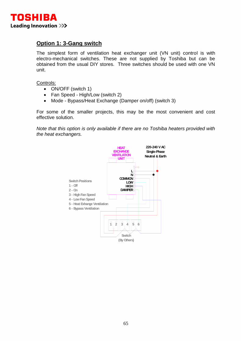
65
Option 1: 3-Gang switch
The simplest form of ventilation heat exchanger unit (VN unit) control is with electro-mechanical switches. These are not supplied by Toshiba but can be obtained from the usual DIY stores. Three switches should be used with one VN unit.
Controls:
ON/OFF (switch 1)
Fan Speed - High/Low (switch 2)
Mode - Bypass/Heat Exchange (Damper on/off) (switch 3) For some of the smaller projects, this may be the most convenient and cost effective solution. Note that this option is only available if there are no Toshiba heaters provided with the heat exchangers.
EXCHANGEVENTILATION
UNIT
HEAT
LN
COMMONLOWHIGH
DAMPER
1 2 43 65
Neutral & Earth
220-240 V AC
Single-Phase
Switch
(By Others)
1 - Off
Switch Positions
2 - On
3 - High Fan Speed
4 - Low Fan Speed
5 - Heat Exhange Ventilation
6 - Bypass Ventilation
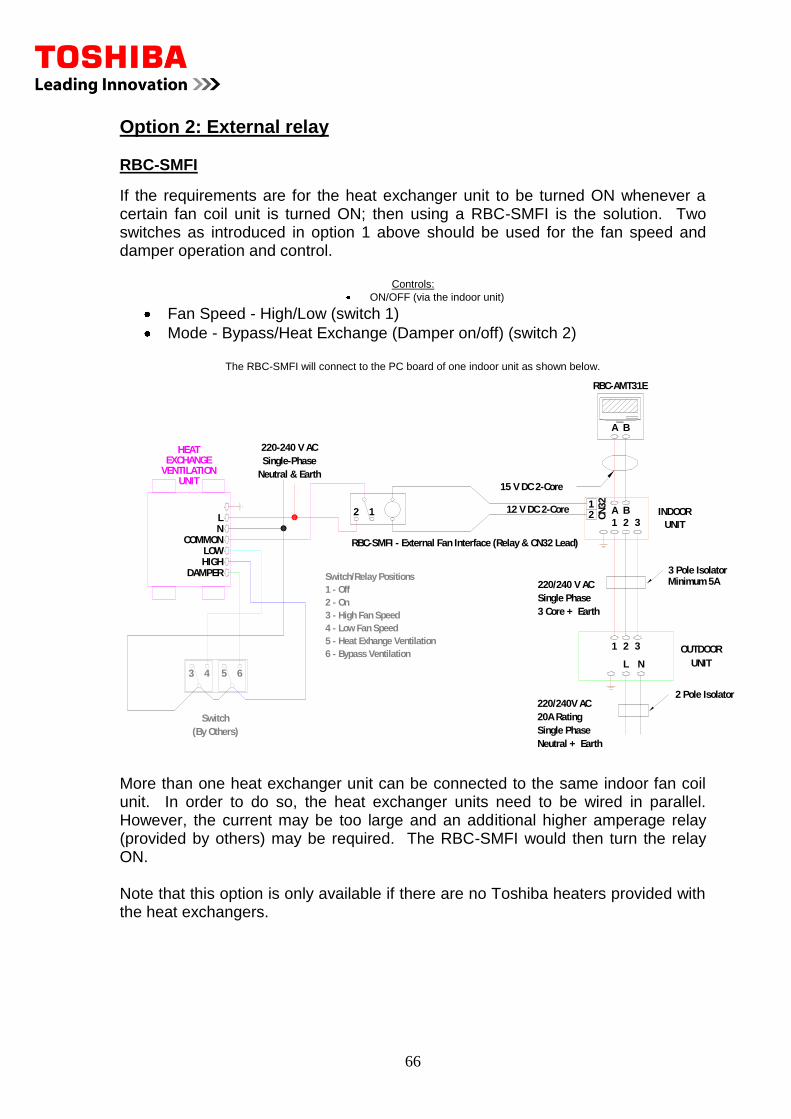
66
Option 2: External relay RBC-SMFI
If the requirements are for the heat exchanger unit to be turned ON whenever a certain fan coil unit is turned ON; then using a RBC-SMFI is the solution. Two switches as introduced in option 1 above should be used for the fan speed and damper operation and control.
Controls:
ON/OFF (via the indoor unit)
Fan Speed - High/Low (switch 1)
Mode - Bypass/Heat Exchange (Damper on/off) (switch 2)
The RBC-SMFI will connect to the PC board of one indoor unit as shown below.
6 - Bypass Ventilation
5 - Heat Exhange Ventilation
4 - Low Fan Speed
3 - High Fan Speed
Switch/Relay Positions
1 - Off
2 - On
A B
2 3
L
321 OUTDOOR
UNIT
20A Rating
220/240V AC
Neutral + Earth
Single Phase
3 Core + Earth
220/240 V AC
Single Phase
INDOOR
15 V DC 2-Core
N
UNIT
2 Pole Isolator
Minimum 5A3 Pole Isolator
EXCHANGEVENTILATION
UNIT
HEAT
RBC-AMT31E
A B
LN
COMMONLOWHIGH
DAMPER
43 65
Neutral & Earth
220-240 V AC
Single-Phase
Switch
(By Others)
1
1212 C
N32
12 V DC 2-Core
RBC-SMFI - External Fan Interface (Relay & CN32 Lead)
More than one heat exchanger unit can be connected to the same indoor fan coil unit. In order to do so, the heat exchanger units need to be wired in parallel. However, the current may be too large and an additional higher amperage relay (provided by others) may be required. The RBC-SMFI would then turn the relay ON. Note that this option is only available if there are no Toshiba heaters provided with the heat exchangers.
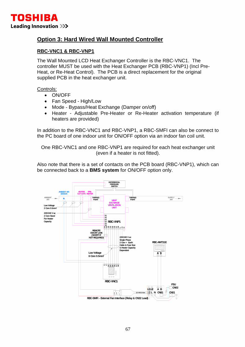
67
Option 3: Hard Wired Wall Mounted Controller RBC-VNC1 & RBC-VNP1
The Wall Mounted LCD Heat Exchanger Controller is the RBC-VNC1. The controller MUST be used with the Heat Exchanger PCB (RBC-VNP1) (Incl Pre-Heat, or Re-Heat Control). The PCB is a direct replacement for the original supplied PCB in the heat exchanger unit. Controls:
ON/OFF
Fan Speed - High/Low
Mode - Bypass/Heat Exchange (Damper on/off)
Heater - Adjustable Pre-Heater or Re-Heater activation temperature (if heaters are provided)
In addition to the RBC-VNC1 and RBC-VNP1, a RBC-SMFI can also be connect to the PC board of one indoor unit for ON/OFF option via an indoor fan coil unit.
One RBC-VNC1 and one RBC-VNP1 are required for each heat exchanger unit (even if a heater is not fitted).
Also note that there is a set of contacts on the PCB board (RBC-VNP1), which can be connected back to a BMS system for ON/OFF option only.
H2
RBC-VNP1H6
S3
S1
S2
S5
S6
S4
H5
H4
H3
Single Phase
2 Core + Earth
220/240 V ac
NLS8
S7
E
AMBIENT AIR
AIRAMBIENT
DIFFERENTIAL
SWITCHPRESSURE
UNITVENTILATIONEXCHANGE
HEAT
HEATERSENSOR
POINT
H1
TAPPING TAPPINGPOINT
SUPPLYAIR
S5T
S3
S4
S8
S7
S6
RBC-VNC1
PRE-CUT-OUTSHEATER
T
2 Core 0.5mm²
Low Voltage
2 Core Sized
220/240 V ac
For Heater
Capacity
Low Voltage
6 Core 0.5mm²
Cable & Fuse Size
is Heater Capacity
Dependant
A B
L N
U1U2
CN01
CN02
CN81
FSU
RBC-AMT31E
RBC-SMFI - External Fan Interface (Relay & CN32 Lead)
12 V DC 2-Core2 1 CN
32
21
ON/OFF LINKREMOTE
(SHORT IFNOT REQUIRED)
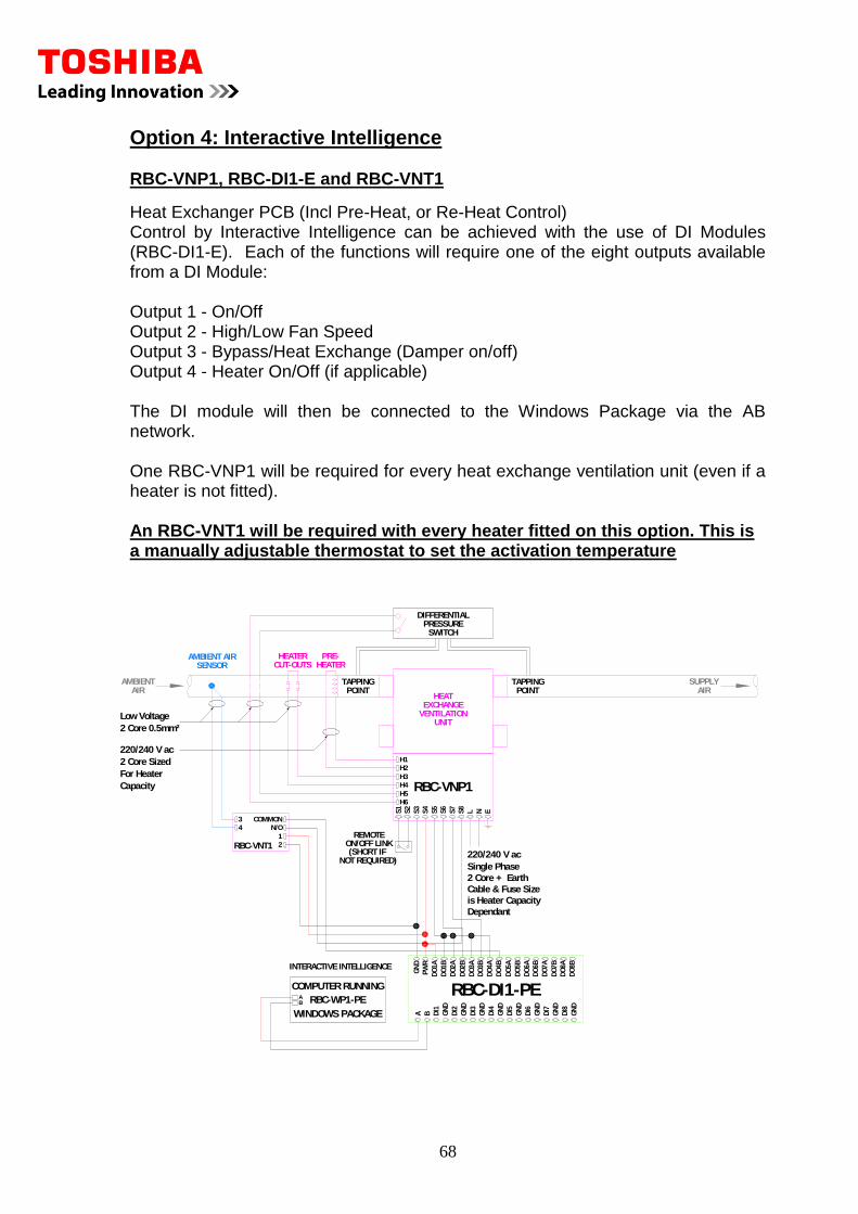
68
Option 4: Interactive Intelligence RBC-VNP1, RBC-DI1-E and RBC-VNT1
Heat Exchanger PCB (Incl Pre-Heat, or Re-Heat Control) Control by Interactive Intelligence can be achieved with the use of DI Modules (RBC-DI1-E). Each of the functions will require one of the eight outputs available from a DI Module: Output 1 - On/Off Output 2 - High/Low Fan Speed Output 3 - Bypass/Heat Exchange (Damper on/off) Output 4 - Heater On/Off (if applicable) The DI module will then be connected to the Windows Package via the AB network. One RBC-VNP1 will be required for every heat exchange ventilation unit (even if a heater is not fitted). An RBC-VNT1 will be required with every heater fitted on this option. This is a manually adjustable thermostat to set the activation temperature
RBC-WP1-PE
COMPUTER RUNNING
WINDOWS PACKAGE
AB
H2
RBC-VNP1H6
S3
S1
S2
S5
S6
S4
H5
H4
H3
Single Phase
2 Core + Earth
220/240 V ac
NLS8
S7
E
AMBIENT AIR
AIRAMBIENT
DIFFERENTIAL
SWITCHPRESSURE
UNITVENTILATIONEXCHANGE
HEAT
HEATERSENSOR
POINT
H1
TAPPING TAPPINGPOINT
SUPPLYAIR
PRE-CUT-OUTSHEATER
ON/OFF LINKREMOTE
(SHORT IF NOT REQUIRED)
2 Core 0.5mm²
Low Voltage
2 Core Sized
220/240 V ac
For Heater
Capacity
Cable & Fuse Size
is Heater Capacity
Dependant
RBC-VNT1
N/O
COMMON
4
3
1
2
DI8
RBC-DI1-PE
DI2
DI1
A B GN
D
DI5
GN
D
DI3
GN
D
GN
D
DI4
GN
D
DI6
GN
D
GN
D
DI7
DO
2B
DO
1A
GN
D
PW
R
DO
1B
DO
2A
DO
5B
DO
4A
DO
3A
DO
3B
DO
4B
DO
5A
DO
7A
DO
6A
DO
6B
DO
7B
DO
8A
GN
DD
O8B
INTERACTIVE INTELLIGENCE

69
Notes

70
Notes

71
Notes
72
The manufacturer reserves the right to change the product specifications and images without notice.
Toshiba products are supplied by: