The Timken Company | Łożyska i mechaniczne przenoszenie mocy
5
Sealing Technology for Primary Metals
Transcript of The Timken Company | Łożyska i mechaniczne przenoszenie mocy

Sealing Technology for Primary Metals
Timken Industrial Seals for Primary MetalsSmelting and steel making is a tough job in an even tougher environment. Extreme temperatures and high levels of contamination can make or break your equipment and productivity. Choose from our selection of sealing products and Prophet software diagnostic tool to help improve the performance of your bearings and equipment while reducing downtime and maintenance costs.
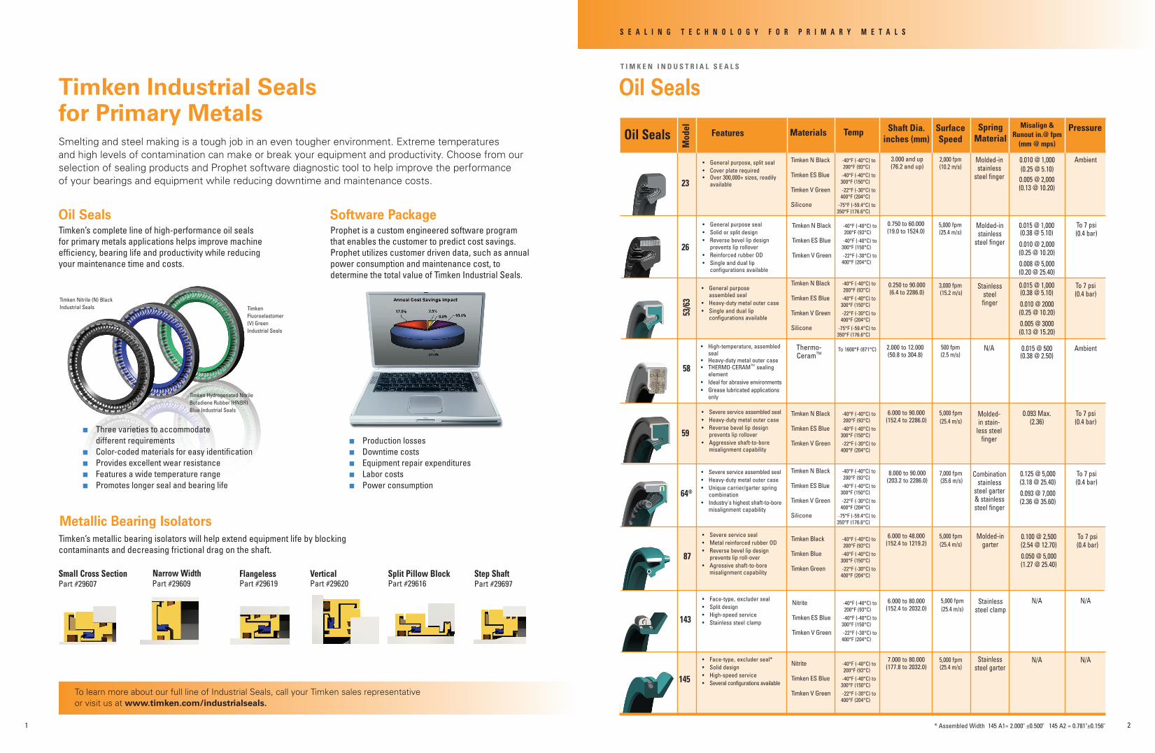
Oil Seals
n Three varieties to accommodate different requirements n Color-coded materials for easy identification n Provides excellent wear resistance n Features a wide temperature range n Promotes longer seal and bearing life
Timken Fluoroelastomer (V) Green Industrial Seals
Timken Hydrogenated Nitrile Butadiene Rubber (HNBR) Blue Industrial Seals
Timken Nitrile (N) Black Industrial Seals
Small Cross SectionPart #29607
VerticalPart #29620
FlangelessPart #29619
Narrow WidthPart #29609
Split Pillow BlockPart #29616
Step ShaftPart #29697
Metallic Bearing Isolators
Software Package
n Production losses n Downtime costs n Equipment repair expenditures n Labor costs n Power consumption
To learn more about our full line of Industrial Seals, call your Timken sales representative or visit us at www.timken.com/industrialseals.
S E A L I N G T E C H N O L O G Y F O R P R I M A R Y M E T A L S
145
• Face-type,excluder seal*• Solid design• High-speed service• Several configurations available
7.000 to 80.000 (177.8 to 2032.0)
5,000 fpm (25.4 m/s)
64®
• Severe service assembled seal• Heavy-duty metal outer case• Unique carrier/garter spring combination• Industry's highest shaft-to-bore misalignment capability
8.000 to 90.000 (203.2 to 2286.0)
7,000 fpm (35.6 m/s)
0.125 @ 5,000(3.18 @ 25.40)0.093 @ 7,000(2.36 @ 35.60)
To 7 psi (0.4 bar)
T I M K E N I N D U S T R I A L S E A L S
Oil Seals
23
• General purpose, split seal• Cover plate required • Over 300,000+ sizes, readily available
3.000 and up (76.2 and up)
2,000 fpm (10.2 m/s)
Molded-in stainless
steel finger
0.010 @ 1,000(0.25 @ 5.10)
26
5,000 fpm (25.4 m/s)
Molded-in stainless
steel finger
53/6
3
• General purpose assembled seal• Heavy-duty metal outer case• Single and dual lip configurations available
0.250 to 90.000 (6.4 to 2286.0)
3,000 fpm (15.2 m/s)
Oil Seals Features Materials Temp Shaft Dia. inches (mm)
Surface Speed
Spring Material
Misalign & Runout in.@ fpm
(mm @ mps)
Pressure
Ambient
• General purpose seal• Solid or split design• Reverse bevel lip design prevents lip rollover• Reinforced rubber OD• Single and dual lip configurations available
0.750 to 60.000 (19.0 to 1524.0)
0.015 @ 1,000 (0.38 @ 5.10)
0.010 @ 2,000(0.25 @ 10.20)0.008 @ 5,000(0.20 @ 25.40)
58
• High-temperature, assembled seal• Heavy-duty metal outer case• THERMO-CERAMTM
sealing
element • Ideal for abrasive environments• Grease lubricated applications only
To 1600°F (871°C) 2.000 to 12.000 (50.8 to 304.8)
500 fpm (2.5 m/s)
To 7 psi (0.4 bar)
Stainless steel finger
0.015 @ 1,000 (0.38 @ 5.10)
0.010 @ 2000(0.25 @ 10.20)0.005 @ 3000(0.13 @ 15.20)
To 7 psi (0.4 bar)
Thermo- CeramTM
N/A 0.015 @ 500 (0.38 @ 2.50)
Ambient
59
6.000 to 90.000 (152.4 to 2286.0)
5,000 fpm (25.4 m/s)
Molded-in stain-
less steel finger
0.093 Max.(2.36)
87
• Severe service seal • Metal reinforced rubber OD• Reverse bevel lip design prevents lip roll-over• Agressive shaft-to-bore misalignment capability
6.000 to 48.000 (152.4 to 1219.2)
5,000 fpm(25.4 m/s)
0.100 @ 2,500(2.54 @ 12.70)0.050 @ 5,000(1.27 @ 25.40)
To 7 psi (0.4 bar)
143
• Face-type,excluder seal• Split design• High-speed service• Stainless steel clamp
6.000 to 80.000 (152.4 to 2032.0)
N/A N/A
N/A
Mod
el
0.005 @ 2,000(0.13 @ 10.20)
5,000 fpm(25.4 m/s)
Stainless steel clamp
N/A
To 7 psi (0.4 bar)
Combination stainless
steel garter & stainless steel finger
Molded-in garter
Stainless steel garter
* Assembled Width 145 A1= 2.000" ±0.500" 145 A2 = 0.781"±0.156"
Timken N Black -40°F (-40°C) to 200°F (93°C)Timken ES Blue -40°F (-40°C) to 300°F (150°C)Timken V Green -22°F (-30°C) to 400°F (204°C)Silicone -75°F (-59.4°C) to 350°F (176.6°C)
Timken N Black -40°F (-40°C) to 200°F (93°C)Timken ES Blue -40°F (-40°C) to 300°F (150°C)Timken V Green -22°F (-30°C) to 400°F (204°C)
Timken N Black -40°F (-40°C) to 200°F (93°C)Timken ES Blue -40°F (-40°C) to 300°F (150°C)Timken V Green -22°F (-30°C) to 400°F (204°C)Silicone -75°F (-59.4°C) to 350°F (176.6°C)
Timken N Black -40°F (-40°C) to 200°F (93°C)Timken ES Blue -40°F (-40°C) to 300°F (150°C)Timken V Green -22°F (-30°C) to 400°F (204°C)Silicone -75°F (-59.4°C) to 350°F (176.6°C)
Nitrite -40°F (-40°C) to 200°F (93°C)Timken ES Blue -40°F (-40°C) to 300°F (150°C)Timken V Green -22°F (-30°C) to 400°F (204°C)
Timken N Black -40°F (-40°C) to 200°F (93°C)Timken ES Blue -40°F (-40°C) to 300°F (150°C)Timken V Green -22°F (-30°C) to 400°F (204°C)
Timken Black -40°F (-40°C) to 200°F (93°C)Timken Blue -40°F (-40°C) to 300°F (150°C)Timken Green -22°F (-30°C) to 400°F (204°C)
• Severe service assembled seal• Heavy-duty metal outer case• Reverse bevel lip design prevents lip rollover• Aggressive shaft-to-bore misalignment capability
Nitrite -40°F (-40°C) to 200°F (93°C)Timken ES Blue -40°F (-40°C) to 300°F (150°C)Timken V Green -22°F (-30°C) to 400°F (204°C)
21
Timken’s complete line of high-performance oil seals for primary metals applications helps improve machine efficiency, bearing life and productivity while reducing your maintenance time and costs.
Timken’s metallic bearing isolators will help extend equipment life by blocking contaminants and decreasing frictional drag on the shaft.
Prophet is a custom engineered software program that enables the customer to predict cost savings. Prophet utilizes customer driven data, such as annual power consumption and maintenance cost, to determine the total value of Timken Industrial Seals.

Usage Range of Temperature Min. Operating Temp Max Spike Temp Max Cont Operating Temp Timken N Black General purpose -40ºF (-40ºC) 250ºF (122ºC) 200ºF (95ºC) Timken ES Blue Excellent heat and abrasion resistance -40ºF (-40ºC) 350ºF (175ºC) 300ºF (150ºC) Timken V Green Excellent heat and chemical resistance -22ºF (-30ºC) 450ºF (232ºC) 400ºF (205ºC) Silicone Wide temperature range -75ºF (-60ºC) 400ºF (205ºC) 350ºF (175ºC) PTFE Superior chemical resistance -120ºF (-85ºC) 450ºF (232ºC) 400ºF (205ºC) THERMO-CERAMTM Ultra high-temp to 1600°F (871°C) 1600ºF (871ºC)
T I M K E N I N D U S T R I A L S E A L S
Aluminum Process
Models 26, 59, 87
HoldingFurnace
Hot MetalFiller
CasterPinchRoll
Pinch Roll Shear
Hot Mill(No. 1Stand)
Hot Mill(No. 2Stand)
CoilStorage, Cooling
Flying ShearLooping
Table
UnwindReel
Cold MillRewind
Reel BeltWrapper
AnnealingFurnace
Schematics courtesy of Davy International
Coil TransferCar
Rewind Reel(No. 1)
Rewind Reel(No. 2)
Models 26, 58
Models 26, 59, 87
Models 59, 64, 87
Models 59, 64, 87
Models 59, 64, 87
Models 59, 64, 87
Models 26, 59Models 26, 59
Models 26, 59
Models 59, 64, 87
Models 26, 59 Models
26, 59
Furnace Table Rolls Model 58 Run Out Table Rolls Model 26 & Non-Metallic Bearing Isolator
Gearboxes Model 26 Motors Non-Metallic Bearing Isolator Pumps Non-Metallic Bearing Isolator Drive Systems Model 26
••
••
•
•
Seal Materials
SILICONE PTFE Filled THERMO- PTFE CERAM™
Other Equipment
•
Models = Seal model on pages 2 & 5
Models GD, IG, EQ,
P/S-II, PK, 26
N/RN/RN/R
N/RN/RN/R *N/R: Not recommended for service
Bronze
•••
3
Models 26, 57, 58
Models 26, GD, IGModels 59, 64, 87, 143, 145Models 59, 64, 87, 145
Models 59, 64, 87, 145 Model 58 Models 59, 64, 87, 145
Models 26, GD, IG
Models 26, 53, 59
Models 59, 64, 87, 145
Models 59, 64, 87, 145
Models 23, 59, 64, 87
Models GD, IG, EQ,
P/S-II, PK, 26
Models = Seal model or style on pages 2 & 5
Models PK Models PK
T I M K E N I N D U S T R I A L S E A L S
Steel Process
4
TIMKENINDUSTRIAL
SEALS
S E A L I N G T E C H N O L O G Y F O R P R I M A R Y M E T A L S S E A L I N G T E C H N O L O G Y F O R P R I M A R Y M E T A L S

T I M K E N I N D U S T R I A L S E A L S
General Engineering Data Tables Table 1 - Shaft Data Hardness RockwellC30to40(RockwellC45minimum willprovideextraprotectionagainstdamage duringhandlingorassembly)
Finish 10-20µin.RA(0.25-0.50µm)with(Plungegrindis nomachinelead,scratches,dents,recommendedas corrosion,pitsorothersurfacedefects mostsatisfactory)
Surfacespeed Formula: Feet-Per-Min.=ShaftDia.(in)xRPMx0.262 Meters-Per-Sec.=ShaftDia.(mm)xRPMx 0.0000524
Safespeed 1.Shaftfinishdependson* 2.Misalignmentandrunout 3.Amountandkindoflubricant 4.Sealdesign 5.Pressure
*Asshaftspeedincreases,thefactorsbecomemorecritical.
Source:RubberManufacturersAssociation
Table 5 - Recommended Shaft Lead Corner
A - Shaft Diameter B - Minimum*
inch mm inch mm Thru0.394 Thru10.00 0.030 0.75
0.395-0.787 10.01-20.00 0.040 1.00
0.788-1.181 20.01-30.00 0.050 1.25
1.182-1.575 30.01-40.00 0.060 1.50
1.576-1.969 40.01-50.00 0.070 1.75
1.970-2.756 50.01-70.00 0.080 2.00
2.757-3.740 70.01-95.00 0.090 2.25
3.741-5.118 95.01-130.00 0.110 2.75
5.119-9.449 130.01-240.00 0.140 3.50
9.450&Up 240.01&Up 0.220 5.50
*Ifashaftlead-inradiusisused,maintainthediametraldifferencetonolessthanindicatedvalue.
Table 3 - Shaft Diameter Tolerances Shaft Diameter Recommended Tolerance
inch mm inch mm
Upto4.000 Upthru101.60 ±0.003 ±0.08
4.001-6.000 101.61-152.40 ±0.004 ±0.10
6.001-10.000 152.41-254.00 ±0.005 ±0.13
10.001&Up 254.01&Up ±0.006 ±0.15
Table 2 - Operating Pressure Limits
Shaft Speed Maximum* Pressure
f/m m/s psi kp (bar)
0-1000 0-5.1 7 48(0.48)
1001-2000 5.2-10.2 5 35(0.35)
2001&Up 10.3&Up 3 21(0.21)
*Timkensplitoilsealsarenotrecommendedforapplicationsinvolvingfluidpressure.
Table 4 - Bore Tolerance
Bore Diameter Bore Tolerances
inches (mm) inches (mm) Upto2.000(50.8) ±0.001(±0.0254)
2.001to3.000(50.8to76.2) ±0.001(±0.0254)
3.001to5.000(76.2to127) ±0.0015(±0.0381)
5.001to7.000(127to177.8) ±0.0015(±0.0381)
7.001to12.000(177.8to304.8) ±0.002(±0.0508)
12.001to20.000(304.8to508) ±0.003(±0.0762)
20.001to40.000(508to1016) ±0.004(±0.1016)
40.001to60.000(1016to1524) ±0.006(±0.1524)
B MIN.
CORNERS MUSTBE BURR FREE
30.0˚ MAX.
A SHAFT (MIN)
Table 6 - Housing Bore Dimensions
CORNERRADIUS
BOREDEPTH
CHAMFERLEGNTH
15˚ MIN.25˚ MAX.
BORE DIA.
Nominal Chamfer Max. Housing Seal Width Length Corner Radius inch mm inch mm inch mm
Thru0.394 Thru10.00 0.03-0.04 0.7-1.0 0.020 0.50
Over0.394 Over10 0.05-0.06 1.2-1.5 0.030 0.75
6
S E A L I N G T E C H N O L O G Y F O R P R I M A R Y M E T A L S S E A L I N G T E C H N O L O G Y F O R P R I M A R Y M E T A L S
Non-Contact Bearing IsolatorsT I M K E N I N D U S T R I A L S E A L S
5
Features Standard Material
Temp Shaft Dia inches (mm)
Surface Speed
Axial Motion
Misalign & Runout in.@ fpm
(mm @ mps)
PressureIsolatorsM
odel
Timken Metallic Isolator
• Bronze** construction• Filled PTFE unitizing ring• Fluoroelastomer O-rings standard
-30°F (-34°C) to 400°F (204°C)
12,000 fpm (60.9 m/s)
Ambient• Meets NEMA MG 1-2003• Surpasses IEEE 841-2001 test standards• Conforms to API 610• No arbor press required for installation• No internal metal-to-metal contact
0.875 to 10.500*(22.2 to 266.7)
± 0.025" (0.64mm)
± 0.020" (0.51mm)
GD
*For large sizes, contact your Timken sales representative. **Other materials available. Consult the Timken Technical Manual or contact your Timken sales representative.
Timken Non-Metallic Isolator
• Excellent chemical resistance• Meets NEMA MG 1-2003• Meets IEEE 841-2001 test standards• No arbor press required for installation
-40°F (-40°C) to 400°F (204°C)
• FDA-compliant, blue glass-filled PTFE**• Fluoro- elastomer O-rings standard
0.875 to 11.000*(22.2 to 279.4)
4,500 fpm (22.9 m/s)
± 0.015" (0.38mm)
± 0.020" (0.51mm)
Ambient
IG
Timken Non-Metallic Isolator
• Excellent chemical resistance• Multi-position capability• No arbor press required for installation• Unique pumping/fanning action
0.875 to 6.000*(22.2 to 152.4)
• Graphite- filled PTFE**• Fluoro- elastomer O-rings standard
-40°F (-40°C) to 400°F (204°C)
4,500 fpm (22.9 m/s)
± 0.015" (0.38mm)
± 0.015" (0.38mm)
Ambient
EQ
Timken Metallic Isolator
• Unique microcellular filter technology• Protects against severely dusty environments• Meets NEMA MG 1-2003• Surpasses IEEE 841-2001 test standards• Conforms to API 610• No arbor press required for installation • No internal metal-to-metal contact
-30°F (-34°C) to 400°F (204°C)
0.875 to 10.500 (22.2 to 266.7)
4,500 f/m (22.9 m/s)
±0.020(0.51) Ambient±0.025
(0.64)• Bronze or 316 stainless steel construction• Silicone foam• Filled PTFE Unitizing Ring• Fluoro- elastomer O-rings standard
MT II

Bearings • Steel • Precision Components • Lubrication • Seals • Remanufacture and Repair • Industrial Services www.timken.com
Timken® is a registered trademark ofThe Timken Company
Model 64® and Thermo-CeramTM are a registered trademarks of Garlock Inc.
Schematics courtesy of Davy International
©2006 The Timken CompanyPrinted in U.S.A.25M 10-06-29 Order No.10062
Distributed by The Timken Company. Timken® Service Parts are carefully chosen from select manufacturers. Keep clean and dry.
Turn to TimkenLike all of our products and services, our seals are backed by our leading technical support and a vast distribution network. Turn to Timken today for a full line of Timken industrial seals that help improve bearing, equipment and bottom-line performance. Visit www.timken.com/industrialseals to learn more.