THE TESTING RUBBER GOODS - NIST
88
DEPARTMENT OF COMMERCE BUREAU OF STANDARDS George K. Burgess, Director THE TESTING OF RUBBER GOODS CIRCULAR OF THE BUREAU OF STANDARDS, No. 38
Transcript of THE TESTING RUBBER GOODS - NIST

DEPARTMENT OF COMMERCEBUREAU OF STANDARDSGeorge K. Burgess, Director
THE TESTING OFRUBBER GOODS
CIRCULAR OF THE BUREAU OF STANDARDS, No. 38

.> rm
DEPARTMENT OF COMMERCEBUREAU OF STANDARDSGeorge K. Burgess, Director
CIRCULAR OF THE BUREAU OF STANDARDS, No. 38
THE TESTING OF RUBBERGOODS
(FIFTH EDITION)
September 26, 1927
(Superseding edition of September 23, 1921)
PRICE 30 CENTS
Sold only by the Superintendent of Documents, U. S. Government Printing Office
Washington, D. C.
UNITED STATESGOVERNMENT PRINTING OFFICE
WASHINGTON1927

-

THE TESTING OF RUBBER GOODS
ABSTRACT
This circular describes the methods used at this bureau in the testing of rubber
goods. The physical tests commonly employed are described in detail and the
machines used for this purpose, many of which were designed at this bureau, are
illustrated and described. Data are given showing the effect of different con-
ditions on the tensile properties of rubber. Special attention is given to the
effect of temperature on the physical tests. The circular also contains a brief
outline of the methods of collecting crude rubber and the processes used in the
manufacture of various rubber articles. The standard procedure of physical
tests and chemical analyses may be found in Federal Specifications Board Speci-
fication No. 59 or Bureau of Standards Circular No. 232 issued by this bureau.
CONTENTSPage
I. Introduction 3
II. Materials used in the industry 4
1. Crude rubber—sources, collection, and preparation 4
(a) Wild rubber 4
(1) Sources 4
(a) Euphorbiacese 4
(b) Apocynacese 5
(c) Asclepiadacese 5
(d) Urticacese 6
(e) Compositse 6
(2) Collection and coagulation 6
(6) Plantation rubber 8
(1) Sources 8
(2) Collection and preparation for market 8
(c) Synthetic rubber 10
(id) Chemical and physical properties of rubber 10
2. Gutta-percha and balata 11
3. Reclaimed rubber 12
4. Rubber substitutes 14
5. Vulcanizing ingredients 14
6. Compounding ingredients 14
o) Fillers 14
(1) Inorganic 15
(2) Organic 15
(b) Accelerators 16
(1) Inorganic 16
(2) Organic 16
(c) Pigments 17
(d) Preservatives 17
1

2 CIRCULAR OF THE BUREAU OF STANDARDS
Page
III. Processes used in the industry 17
1. Washing of crude rubber .
v
17
2. Drying 19
3. Compounding or mixing 19
4. Calendering 19
5. Frictioning 20
6. Vulcanization 21
() Open steam cure 21
() Press cure 21
(c) Cold cure 21
(d) Bath cure 23
(e) Hot-air cure 23
(f) Vapor cure 23
(<7) Hot-water cure 23
(/?) Gas cure 23
7. Electrodeposition of rubber 23
IV. Manufacture of rubber goods 24
1. Solid rubber tires 24
2. Cushion tires 24
3. Pneumatic tires 24
4. Inner tubes 27
5. Plied hose 28
() Machinemade hose 28
() Handmade hose 29
6. Braided hose with rubber tube and cover 29
7. Cotton rubber-lined hose 30
8. Rubber tubing 30
9. Rubber belting 30
10. Molded rubber goods 31
11. Insulated wire 31
12. Rubber boots and shoes 32
13. Rubberized fabrics 33
14. Dipped goods and druggists’ sundries 34
15. Rubber bands and thread 35
16. Sponge rubber 35
17. Rubber cements 36
18. Hard rubber 37
V. Testing of rubber 38
1. Physical testing of soft rubber 39
(a) Comparison of normal and accelerated aging 41
( b) Tensile strength and ultimate elongation 42
(1) Separating rubber from fabric 42
(2) Abrasive machine for buffing the surface of
rubber 43
(3) Form and preparation of test pieces 44
(4) Measuring the thickness of rubber 47
(5) Grips for holding test pieces 48
(6) Testing machines 48
(c) Elasticity or “set” 52
(1) Machine for testing elasticity or “set” 52
(d) Reduction in tension when rubber is held at a
definite elongation 53
(1) Machine for testing reduction in tension 54

TESTING OF RUBBER GOODS 3
V. Testing of rubber—Continued.
1 Physical testing of soft rubber—Continued. Page
(e) Conditions affecting the results of tension tests 55
(1) Influence of speed on tensile strength and
ultimate elongation 55
(2) Influence of temperature on strength, elonga-
tion, and elasticity 55
(3) Influence of cross section on tensile strength
and ultimate elongation 56
(4) Influence of the direction in which speci-
mens are cut on strength, elongation, and
elasticity 57
(5) Influence of “backing” on the tensile
strength and elasticity of hose lining 58
(6) Influence of previous stretching on strength,
elongation, and elasticity 59
(7) Influence of the form of test piece on the
results of tension tests 60
(/) “Friction” test 65
(g) Hydraulic-pressure test 68
(h) Steaming test 70
(i) Testing the rubber insulation of wire 70
(j) Comparative tests of machine and handmade tubes. _ 70
(k) Testing of rubber bands 73
(1) Under one-fourth inch in width 73
(2) Bands one-fourth inch in width or over 73
(il) Abrasive resistance of rubber compounds 73
2. Physical testing of hard rubber ~ 75
() Tensile strength 75
() Impact tests 76
(c) Cold flow test 76
(d) Other tests 76
3. Chemical analysis of rubber 76
VI. Appendix 80
1. Standard procedure for tests and analyses 80
2. Specifications for rubber goods promulgated by the Federal
Specifications Board 80
3. Publications of the Bureau of Standards relating to rubber. _ 81
4. Books 82
5. Periodicals 83
I. INTRODUCTION
The testing of rubber goods is receiving increased attention, and
the necessity of maintaining standards of quality has resulted in.
the preparation of master specifications for the purchase of rubber
goods by the Government. The purpose of this circular is to describe
the methods used for testing rubber at this bureau, and in order that
the fundamental principles involved in these tests may be appre-
ciated, reference is made to the sources and preparation of rubber,
and a brief description of some of the manufacturing processes is
given.

4 CIRCULAR OF THE BUREAU OF STANDARDS
Much remains to be done in the refinement of testing methods nowin common use and in the development of new tests, the results of
which shall more nearly express the particular qualities desired in
rubber. This applies to crude rubber as well as to materials fabri-
cated from rubber. The technical staffs of the rubber industry are
working together along this line, and it is hoped that more exact
criteria of quality will result.
II. MATERIALS USED IN THE INDUSTRY
1. CRUDE RUBBER—SOURCES, COLLECTION, AND PREPARATION
Crude rubber is obtained by the coagulation of a milky fluid called
latex which is contained in a special cell system (laticiferous system)
of certain trees, vines, shrubs, and roots, and also from the cellular
tissue of certain shrubs and vines. The laticiferous system, which
is distinct from the sap-bearing cell system, generally lies between
the outer bark and the cambium, the soft, rapidly growing tissue
from which new wood and bark are formed; by cutting through the
bark the latex is obtained as a white to cream colored, more or less
viscous, fluid containing ordinarily from 30 to 35 per cent of solids.
This operation is termed “ tapping.’’ Rubber exists in the latex
as small particles varying in size from 0.5 to 3 microns (0.00002 to
0.00012 inch), which are suspended in a serum. The rubber is sepa-
rated from the latex by coagulation. This is accomplished on the
plantation by acetic acid. The coagulated rubber is separated
from the serum, washed thoroughly, and dried.
Rubber is also obtained by spraying the latex into a heated chamber.
The latex flows upon an elevated, horizontal, rapidly revolving
disk, which hurls it into a current of heated air. The water is thus
removed and the rubber descending in fine particles collects on the
floor of the chamber in the form of a sponge. The sponge is com-
pressed into blocks for shipment. Latex sprayed rubber contains
all the water-soluble material originally present in the latex.
Latex, with a small amount of ammonia added to prevent coagula-
tion, is used to impregnate fibrous materials, such as fabrics and cords
for automobile tires. When it is used as a cement the danger result-
ing from the employment of inflammable organic solvents is avoided.
(a) WILD RUBBER
(1) Sources.—Rubber-bearing species are indigenous to con-
siderable tracts of the tropical and subtropical zones of South and
Central America, Asia, Africa, and Australia. The chief botanical
orders are the Euphorbiaceae, Apocynaceae, Urticaceae, and Com-positae.
(a) Euphorbiacese .—The most important genus of this order is
the “Hevea,” and from the species H. brasiliensis at least three-

TESTING OF RUBBER GOODS 5
fourths of the world’s output of rubber is obtained. From this
we get the famous Para rubber. There are two main districts in
which fine Para rubber is prepared: (1) The “islands” at the mouthof the Amazon River and (2) the “up river” regions near and above
Manaos.
The scraps of rubber adhering to the trees and tapping cups are
compressed into irregular masses and sold as “negroheads.” Up-river negroheads are generally termed “scrappy.” Island negro-
heads go by the name of “Sernamby.” A third variety of negro-
head, the Cameta, comes from the district of that name in southwest
Para.
Among the other varieties of rubber from H. brasiliensis may be
mentioned
:
()
( )
(c)
(d)
(e)
Matto Grosso, fine and entrefine,l, _ „
Matto Grosso, virgin sheets,Fr°m the Provlnce °f Matto Gross°>
Matto Grosso, negroheads. j
razl '
Mollendo (Bolivian Para).
Peruvian (fine, coarse, or scrappy)
.
Although the rubbers referred to above consist mainly of H. brasil-
iensis, the latices of other species of Hevea, such as spruceana,
itaube, discolor, similis, and speciosa, are also employed to someextent in their preparation.
Another genus of the Euphorbiacese is the Manihot. The most
important commercial variety is the Manicoba or Ceara, which
comes from the Province of Ceara, Brazil.
(b) Apocynacex .—The bulk of native African rubbers belongs to this
order, and the main genera are Funtumia, Landolphia, and Clitandra.
The only species of Funtumia which is of commercial importance
is F. elastica. The natural habitat of the tree is on the Gold and
Ivory Coasts, in Uganda, and in other parts of tropical Africa. Therubbers are known as Gold Coast lumps, Ivory Coast lumps, Niger
niggers, Benin lump, Congo, and Cameroon.The species of Landolphia are all creepers or vines, which attain
considerable size. They yield red and black Kassai, Upper Congoballs, and Equateur from the Congo region; virgin sheets and pinky
from Madagascar; Sierra Leone niggers, twists, and cakes, all from
the Sierra Leone and southern rivers; and Konakry, Sudan, and
Bassam niggers and twists from French West Africa.
The species of Clitandra are likewise vines and are largely dis-
tributed throughout Africa.
In certain Brazilian Provinces the Hancornia, which yields the
rubber known commercially as Mangabeira or Matto Grosso sheets,
occurs in considerable quantity.
(c) Asclepiadacex.—A rubber of high resin content termed Jelutong
is obtained from species of Dyera, the most common being D. costu-

6 CIRCULAR OF THE BUREAU OF STANDARDS
lata. Species of Dyera are among the commonest forest trees in
Borneo, the Malay Peninsula, and Sumatra^ Pontianak is a variety
of Jelutong grown in South Borneo.
(d) Urticacese.—The most important species of this order occur in
tropical Asia, Mexico, and South and Central America.
Ficus elastica is found mainly in Asia (Burma, Ceylon, Malaya,
Java, and India). The principal commercial brands are Assam,
Rangoon, Java, and Penang.
The species of Castilla (principally C. elastica and C. ulei) represent
the indigenous rubber trees par excellence of Mexico and Central
America. We have Peruvian “caucho” rubber from Peru, Negrocaucho from Ecuador, and Mexican strips and the different “WestIndian” or Centrals from Costa Rica, Nicaragua, Honduras, SanSalvador, and Guatemala.
(e) Composite.—The name guayule is derived from the Spanish
“hay” and the Indian “hule” or rubber yielder. The rubber-bearing
species is Partlienium argentatum. It is a gray woody shrub of
spreading habit, growing generally betwmen 1 and 3 feet high. It
differs from other rubber-bearing plants in that it has no latex but
contains the rubber in the cellular tissue of the epidermis and to a
small extent in the branches and leaves. The plant, when cut to the
ground, will send up new shoots if rain falls within a certain time.
Guayule is now cultivated scientifically on plantations in California
and southern Arizona. The quality of the product has been muchimproved in recent years.
(2) Collection and Coagulation.—In the Amazon district the
trees are tapped by means of a small iron hatchet having a blade about
1 inch broad. The incisions are generally made in the form of
V-cuts or oblique lines. The first tappings are made at a height of
from 6 to 7 feet, and subsequent incisions at roughly to 2 inches
below the first one until the base of the tree is reached. About 35
consecutive daily tappings are therefore necessary to complete a
tapping line. A fresh tapping line is then commenced at approxi-
mately 18 inches from the first one. The latex is collected in small
metal or earthenware cups fixed to the tree by means of moist clay.
The annual yield of rubber from the average Amazon tree is about
5 pounds. The latex is transferred to pails and is coagulated by a
smoking process.
In a small brazier a fire is made from palm nuts. A long woodenrod or paddle is so arranged, one end on a crosspiece, the other onthe operator’s knees, that it can be rolled either over the top of the
chimney and so be exposed to the full volume of smoke, or over the
basin containing the latex. The operator pours a small quantity
of latex over the wooden paddle and thus forms a thin film of liquid.
This is rotated in the smoke until it sets. A fresh quantity of latex

TESTING OF RUBBER GOODS 7
is then poured upon the first film, smoke is again applied, and so onuntil a “ biscuit” or ball of rubber of the required size (20 to 100
pounds), consisting of innumerable thin layers tightly adhering to
one another, is formed. The ball is then removed from the paddle
and is ready for export as the “fine Para” of commerce.
There is some difficulty in collecting the latex from the Manihottrees, owing to its viscous character and its property of rapidly
coagulating. The natives allow the latex to coagulate naturally
as it flows down the tree, and the bulk of the rubber is collected
in tears and scraps which are stripped off. A certain amount of latex
reaches the ground and this is collected on leaves or directly from
the soil.
The African rubber trees of the genus Funtumia are tapped in
a manner similar to that used on the Hevea trees. The collecting
is done entirely by the natives, and relatively little is known of
their methods. Funtumia latex coagulates readily on boiling and
most native methods are based on this fact.
The methods employed by the natives for coagulating vine latices
are of the most diverse kinds. Thus, red Kassai is said to be obtained
by smearing the latex on the body and allowing the natural heat to
evaporate the water, after which the rubber is stripped off. Black
Kassai is obtained by a combined boiling and smoking process.
Some of the “ball” rubbers are obtained by applying a coagulant,
such as salt, to the cuts made in the vine. The thread rubber thus
obtained is wound into a ball of the desired size. More salt is added
at intervals so as to maintain constant coagulation. Vines do not
readily lend themselves to tapping. They are generally cut downand bled to death.
Jelutong is obtained from a number of species of Dyera. Thetrees grow to a very large size, those having a diameter of from
4 to 6 feet being quite common. A mature tree will yield about 100
pounds of latex per year with 40 tappings. The latex is rich in solids
and will yield about 65 per cent of wet but solid Jelutong. Thelatex is coagulated by the natives, who use curious mixtures of kero-
sene, copper sulphate, and alum. The solid matter in Jelutong,
however, is quite largely resin and contains only a small percentage
of rubber.
The wild guayule shrub is generally collected by pulling up the
entire plant, which is baled for shipment to the factory for extraction.
Special methods are used to obtain the crude rubber because it is
held in the cells of the plant. The dry plant yields about 9 per cent
of pure rubber, although the percentage is often greater. Whenguayule is cultivated the shoots are cut off near the ground without
destroying the plant. The yield is from 10 to 20 per cent of the
weight of the dry shrub. Three types of processes have been used

8 CIRCULAR OF THE BUREAU OF STANDARDS
for the extraction of rubber from the plant: (1) The alkali process, in
which the shrub is boiled with a solution of caustic alkali; (2) the
solution process, in which the rubber is extracted with carbon bisul-
phide or some other solvent; and (3) the mechanical process. Thegreat bulk of guayule rubber is obtained by the last process. Theshrub is crushed and ground in pebble mills with water. The material
is then run into settling tanks where the water-logged woody fiber
sinks while the rubber floats and is skimmed off. It is then sheeted
and washed on rubber mills and dried. The rubber so obtained is
quite dark in color on the surface and contains about 20 per cent of
resin, which can be removed. When used with the better grades of
rubber, as plantation sheets and crepes, good results are obtained with
modern compounding methods.
(b) PLANTATION RUBBER
(1) Sources.—The plantation rubbers are obtained chiefly from
Ceylon, the Federated Malay States, Dutch East Indies, Borneo, and
the Pacific islands.
The tree which is now almost exclusively grown on these planta-
tions is the Hevea brasiliensis . The Hevea grows in a narrow belt
on both sides of the Equator, provided there is plenty of moisture.
Before planting, a great amount of work must be done to clear the
land, by cutting down the trees and underbrush, which are burned
when dr}L The deadwood is removed and not allowed to rot uponthe ground. From this point on, a vast amount of labor is required
to keep out the weeds. The seeds are carefully selected from trees
which give the greatest yield of rubber, and extreme care is taken in
their propagation. One or two year old plants from the nurseries
are set out during the rainy season at from 50 to 200 to the acre. In
close planting there may be 400 to 500 trees per acre. The trees
increase in height from 6 to 10 feet a year and in girth from 3 to 5
inches. They are not ready for tapping until 5 or 6 years old. Theannual yield from such young trees is less than a pound of rubber
each, and gradually increases as the trees grow older. The mature
trees yield as much as 15 pounds or more of rubber per year.
The first Hevea seeds from which the plantations were started
were smuggled out of Brazil and no care was taken to collect themfrom the best trees. The propagation of the trees by budding is
being tried on some new plantations, but it is not yet certain that
trees of uniformly high yield can be obtained in this way.
(2) Collection and Preparation for the Market.—Methodsof tapping rubber trees undergo frequent change. The herringbone
system consists in making a series of oblique cuts which run into
a central channel from one side. In the basal V system the cuts
meet in the channel from each side. The present practice is one cut
per tapping on one-quarter to one-half of the circumference. Cuts

TESTING OF RUBBER GOODS 9
must be made with care. Each cut removes a strip of bark one-
thirtieth to one-twentieth of an inch wide. Methods of tapping are
still a matter of experiment. Trees are tapped from daylight to
about 9 a. m. On some plantations, trees are tapped daily; on
others they are tapped on alternate days. Period tapping consists
in collecting the latex for a month and allowing the tree to rest for
a month. When tapping is resumed, the tree appears to have lost
the habit of yielding latex and does not produce its maximum yield
for a short time.
Plantation latex is generally coagulated by the addition of a
small quantity of acetic acid. For producing pale crepe advantage is
taken of the bleaching action of sulphurous acid by adding sodiumbisulphite to the latex. Formic acid has replaced acetic acid as a
coagulant on some plantations because only half the quantity is
required.
The amount of coagulant largely determines the character of the
coagulum, which may be soft like the coagulum of milk obtained with
rennet, or may have the consistency of a stiff jelly. The stiffer
coagula are rolled and washed with more difficulty than the softer.
The treatment to which the rubber coagulum is subjected has an
important bearing on the quality and market value of the rubber.
One of two courses is usually adopted: (a) The rubber is merely
sheeted by the action of washing rolls, by which process an appreci-
able quantity of the nonrubber constituents of the latex is retained.
In order to avoid mold or tackiness, the rubber is thoroughly smoked.
(b) The rubber is converted into thinner sheets called crepe andthoroughly washed during the process to remove the other con-
stituents of the latex as far as possible. The washing rolls squeeze out
the serum, or watery portion from the coagulum and wash out the
excess of the other nonrubber constituents of the latex. These rolls
are of much the same construction as those used in the factory for
washing. (See fig. 1.)
The rubber as it leaves the washing rolls is in sheets about one-
eighth inch thick and 10 to 14 inches wide; the length may vary from
a few feet up to 30 or 40 feet. These sheets are hung in a room at a
temperature not higher than 120° F. until they are dry. Some-times the room is kept full of smoke during the drying process.
Almost any hardwood, coconut husks, or the like may be used to
produce smoke. Smoke acts as an antiseptic and preservative of
rubber. The sheets of rubber are pressed into blocks for export.
Crepe rubber is air-dried at about 100° F. and dried in vacuo at
about 120° F.
It is interesting to note the tremendous development of the pro-
duction of plantation rubber. According to statistics1 published
1 Rubber Division, United States Department of Commerce.

10 CIRCULAR OF THE BUREAU OF STANDARDS
by the United States Department of Commerce, practically nonewas produced in 1900; in 1910 about 8,00(1 tons, and in 1926 morethan 580,000 tons were produced. The plantation acreage increased
from slightly over 1,000,000 acres in 1910 to about 4,300,000 acres
planted area in 1923. The annual production of rubber, mostly wild,
from tropical America and Africa in 1910 was about 70,000 tons,
and in 1925 was about 40,000 tons. Unless plantation production
methods are adopted or unless market prices for the commodityprevail at a high level over long periods this amount will not be
increased. The net imports of the United States for each year
from 1921 to 1925 have averaged about 73 per cent of the total
imports into all countries.
An illustrated description of the production of plantation rubber
may be found in a publication of the United States Department of
Commerce entitled “The Plantation Rubber Industry in the MiddleEast.”
(c) SYNTHETIC RUBBER
Synthetic rubber has been made by the gradual polymerization of
the hydrocarbons butadiene, monomethylbutadiene (isoprene), anddimethylbutadiene (methylisoprene). Each yields a different type
of rubber of somewhat different composition and properties. Theparent substance of natural rubber is isoprene and many attempts
have been made to produce isoprene on a commercial scale. Theso-called English synthesis employs higher alcohols and aldehydes
which in turn may be obtained from starch. The German syn-
thesis makes use of the coal-tar products cresol and phenol. Acetone
is an important raw material which can also be obtained from starch.
Several promising syntheses of isoprene based on the use of acetone
are possible. The ultimate success of synthetic rubber will not be
assured unti] it is possible to reproduce the condition that is called
the degree of polymerization or aggregation of natural rubber.
This involves its molecular and physical structure. It is a greater
problem than the mere synthesis of a crystalline, organic compound.
Synthetic rubber oxidizes readily, requires accelerators for vul-
canization, and its physical properties are comparable with those of
the poorer grades of natural rubber. Unless synthetic rubbers can
be made as good as the natural rubbers and as cheaply, they will
not be manufactured commercially.
(d) CHEMICAL AND PHYSICAL PROPERTIES OF RUBBER
Rubber belongs to the class of compounds known to the chemist
as hydrocarbons; that is, substances which contain only the elements
carbon and hydrogen. Harries, Weber, and other investigators
determined that the formula for the rubber molecule is polyprene
(C 5H8)x, which is derived from the simpler hydrocarbon isoprene

TESTING OF RUBBER GOODS 11
(C5H8 ). All attempts to make synthetic rubbers are based upon the
acceptance of this formula for the rubber molecule.
The specific gravity of clean commercial rubber is about 0.92, but
varies with the species, method of coagulation, and purity; the val-
ues obtained by various investigators are from 0.91 to 0.97. Onwarming, unvulcanized rubber becomes soft and sticky and is partly
decomposed by the heating. When the rubber is cooled, it does not
regain its original properties but remains as a semifluid, sticky mass.
At temperatures below the freezing point of water rubber loses its
elasticity and becomes rigid, and on immersion in liquid air it becomes
brittle. It is insoluble in water, but upon soaking in water for a
long time it will absorb considerable quantities. It dissolves in a
number of organic solvents, such as benzene, chloroform, carbon
bisulphide, naphtha, etc. Rubber is a poor conductor of electricity
and heat. It is not affected by alkalies or dilute acids, but con-
centrated sulphuric acid or nitric acid attacks it. It is gradually
oxidized in air, with the formation of resin.
2. GUTTA-PERCHA AND GUTTA-BALATA
These substances are not rubber, but have many properties similar
to those of rubber, and are used in the rubber industry.
Gutta-percha is obtained from various trees, belonging to the
natural order Sapotace*, growing on the Malay Peninsula and the
Archipelago. The trees of the species Palaquium oblongijolium and
Palaquium obovatum are the main sources. Palaquium oblongijolium
is being raised on plantations at Tjipetir, Java. The gutta is obtained
from the leaf by a mechanical process. The plantation product has
a much higher market value than that of gutta from other sources.
The latex from uncultivated areas is collected generally by cutting
down the tree and ringing the bark at intervals of 12 to 18 inches
along the trunk. The milky fluid fills the grooves, soon coagulates,
and is scraped off with a knife. Some latices do not coagulate
quickly, and these are collected in vessels. They are gently boiled
with or without the addition of water. The raw gutta is cut up,
softened in hot water, washed on a washing machine, and then
forced through a strainer. After a second washing the inclosed
water is forced out by a kneading machine and the mass is sheeted
out in 5-foot slabs one-eighth to one-fourth inch in thickness. Themethod of collecting the latex by cutting down the trees is extremely
wasteful.
Commercial gutta-percha is hard and tough, but on warming to
115 to 122° F. it can be pressed into any shape, which it will retain
on cooling. Its main use is for the insulation of submarine cables.
It is also used for temporary dental fillings, leather cements, andfor golf balls.

12 CIRCULAR OF THE BUREAU OF STANDARDS
Gutta-percha consists of 30 to 84 per cent of “gutta,” a rubber-
like material, and 10 to 60 per cent of resin,^which consists of albane,
a crystalline resin, and fluavile, a yellow amorphous resin, in the
ratio of about 2 to 1.
Gutta-balata is obtained from the latex of the Mimusojps batata
and Mimusops globosa trees growing in British, Dutch, and French
Guiana. The commercial product comes in slabs about one-fourth
inch thick, is horny, and from white to dark cream in color. It is
collected by tapping as well as by felling the trees in the same manneras gutta-percha, for which it is the only substitute. It has similar
properties, although it is somewhat softer, owing to the fact that
it contains more of the softer resin fluavile. It contains the resins in
the proportion of approximately 2 parts of albane to 3 parts of
fluavile. The main use of gutta-balata is in the manufacture of
belting for power transmissions. It is also used in golf balls.
3. RECLAIMED RUBBER
The object in reclaiming rubber is to restore useful properties to
the scraps of worn-out articles, so that the material may be used
again. The aim is to restore to the vulcanized rubber the properties
of crude rubber. This has not been accomplished fully, for no one
has yet succeeded in removing the combined sulphur and regenerat-
ing the rubber molecule in its original state.
Reclaimed rubber is a plastic product prepared by subjecting
vulcanized rubber scrap to processes of grinding, chemical treatment,
and refining. Over 140,000 long tons were produced in 1925, and
about 175,000 tons in 1926.
The first commercial reclaimed rubber product was known as
“ rubber shoddy.” Old boots and shoes were ground, the loosened
fiber blown out, and the residue treated with live steam for 8 or 10
hours. Later, in a modification of the process, the fiber was disinte-
grated by treatment with sulphuric acid. “Rubber shoddy,” imper-
fect as it was, proved to be of value in rubber footwear, clothing, and
chiefly in carriage cloth, in which it gave excellent service. Somerubber manufacturers regrind uncured and even vulcanized factory
scrap and use it in new batches of compounds. During 1926 morethan 13,000 long tons of such scrap was used in this manner.
Nowadays used rubber is reclaimed in large plants, under close
technical supervision. The product obtained is plastic and mixes
readily with new rubber, sulphur, and other compounding ingredients.
Rubber compounds consisting partly of reclaimed rubber serve a
useful purpose in the production of footwear and rubber heels, wire
insulation, hose, and tires.
To be successful, the treatment of scrap rubber demands consid-
erable investment in power plant, digesters, rubber mills, and similar

TESTING OF RUBBER GOODS 13
necessary equipment. The plants must have ample space for the
storage of raw material and products, and must be located close to
an adequate and constant source of supply of used rubber. Theprice of crude rubber to some extent influences the demand for
reclaim. However, reclaimed rubber, even during the period of
low prices for crude in recent years, has been in constant demand.
The modern process begins with the sorting of the scrap. Although
subject to a recognized classification by the dealer, the reclaimer sorts
it again before processing. Each assortment is finely ground and the
ground waste passed over screens and magnetic separators.
From this point the removal of fiber is accomplished chiefly bythe acid process of Mitchell or the alkali process of Marks. By far
the largest amount of reclaimed rubber on the market is produced
by the alkali process. In the acid process the ground scrap is treated
with dilute sulphuric acid in lead-lined vats, at the bottom of which
live steam is injected. The fiber is slowly weakened and destroyed.
This requires as much as four hours or more. The rubber is washedfrom the disintegrated fiber, generally passing over rifflers which
remove sand and metal. After thorough washing the mass as a
rule is mixed with oils, tars, or other softeners and conveyed to large
digesters. Live steam is forced into the mixture for 24 to 48 hours
at a pressure of 100 to 150 pounds. This treatment plasticizes the
rubber and removes part of the free sulphur. The plasticized
mixture is then dried.
When the alkali process is used the ground rubber containing fiber
is treated in digesters with dilute caustic soda of a strength varying
from 2 to 8 per cent. The fiber is disintegrated and dissolved at
150 pounds steam pressure in from 8 to 24 hours. A considerable
amount of free sulphur is removed from the rubber. It is washedin tanks until practically free from alkali, sometimes run over rifflers
and finally dried. The dry rubber is softened by working on a rubber
mill and then forced through a heavy cylindrical strainer attached
to a tubing machine. The rubber emerges as strings, free from coarse
particles of metal, grit, and similar impurities. The amount of metal
removed at this late stage of the process is astonishing. The rubber
is then passed between heavy rolls and appears as an extremely thin
sheet. These sheets are converted into slabs or cylinders about 4
inches in diameter. The various grades of reclaimed rubber are very
well reproduced in spite of variations in the scrap.
No reclaimed rubber has yet been produced which is equal to good
new rubber. It is more or less inferior in strength and stretch. How-ever, reclaimed rubber is a valuable ingredient in many classes of
rubber goods when properly compounded to meet the conditions of
service required.
14 CIRCULAR OF THE BUREAU OF STANDARDS4.
RUBBER SUBSTITUTES
No true rubber substitute—that is, no material possessing all the
properties of rubber—has yet been produced. The term “ rubber
substitute” is commonly applied to materials which are produced byvulcanizing certain vegetable oils, such as rapeseed, corn, and cotton-
seed oils, either by treatment with cold sulphur chloride or by heat-
ing with sulphur. The sulphur-chloride process produces “ white
substitute,” while that made with sulphur is known as “ brown sub-
stitute.” These substitutes are used in the manufacture of cheap,
soft-rubber articles of low specific gravity. Their use tends to reduce
the strength, elasticity, and wearing qualities of the finished product
and they are unsuited for making articles which are to be subjected
to high temperatures.
The so-called mineral rubbers should not be considered forms or
varieties of rubber. They are bituminous materials, either natural
products, such as gilsonite or other types of asphalt, or the crude tar
residue from the distillation of petroleum.
5.
VULCANIZING INGREDIENTS
Charles Goodyear in America and Thomas Hancock in England
independently observed the effect of sulphur on rubber at an elevated
temperature. Goodyear, to whom priority is given for the discovery,
called the process vulcanization. Vulcanization is also called “curing”
in rubber factories. Ground roll sulphur is ordinarily used in rubber
compounds to effect vulcanization. The vulcanization of rubber bymeans of sulphur chloride at ordinary temperatures is called cold
curing. There are forms of active sulphur which cure rubber at
room temperature. The reaction between the gases hydrogen sul-
phide and sulphur dioxide produces active sulphur. This reaction is
used in the Peachey process of vulcanization. Vulcanization has
been accomplished by substances other than sulphur, such as selenium,
trinitrobenzene, and other organic compounds. Hard rubber requires
a larger amount of sulphur and a longer cure in its manufacture than
soft rubber.
6.
COMPOUNDING INGREDIENTS
The substances that are mixed with rubber in the manufacture of
rubber goods comprise a list of materials of widely varying natures.
The rubber compounder finds it advantageous to classify these sub-
stances into definite groups, although often there is some overlapping
between them.
The ingredients may be classified as follows: (a) Fillers (1, inor-
ganic; 2, organic); (b ) accelerators (1, inorganic; 2, organic); (c) pig-
ments; (d) preservatives.(a) FILLERS
Certain fillers when mixed with rubber add qualities to the com-
pound which makes their use desirable. A number are added merely

TESTING OF RUBBER GOODS 15
as cheapeners and impart no desirable properties. If an excess of
fillers is used, their effect on the compound may be detrimental.
The cost per unit volume is often the determining factor in the use
of one filler in preference to another.
(1) Inorganic Fillers.—Among the inorganic fillers are those
which, when added to rubber, impart certain definite properties,
such as toughness increase in tensile strength, hardness, compressive
strength, increased insulating properties, and resistance to steam andto abrasion. In general, a filler should be in a state of fine division.
The following fist contains the most frequently used fillers and someof their general properties :
Carbon black, zinc oxide, clay, lithopone, lampblack, and magne-sium carbonate not only slightly increase the rate of vulcanization,
but have a decided toughening effect on the rubber. Gas black or
carbon black is a valuable pigment in rubber goods. Hancock ob-
served that black stocks resist the action of sunlight, which has a
deleterious effect on vulcanized rubber.
A good color may be obtained by mixing 2 per cent of gas black
with rubber. The effect of greater quantities depends on the char-
acteristics of the black. Some black produces soft stocks and others
have a toughening or stiffening effect on rubber compounds.
Aluminum flake, whiting, barytes, and barium carbonate impart
no special properties and are considered as being inert. Some types
of clay stiffen or reinforce rubber compounds; others are inert fillers.
Tripoli (infusorial earth), talc, and soapstone tend to make the
compound dry and stiff. Talc and soapstone are used mainly for
dusting sheets of unvulcanized rubber and molds to prevent sticking
during vulcanization. Asbestine is used in heat-resisting compounds;
powdered glass and pumice are used in erasers.
Hard-rubber dust is a common filler in hard-rubber goods. It is
occasionally used in soft-rubber compounds. Ground fused quartz
has been suggested as a filler in certain types of insulation.
(2) Organic Fillers.—The organic fillers include a large numberof oils, vulcanized oils, waxes, paraffins, bitumens, and pitches. Theyare used mainly to facilitate the mixing of the inorganic fillers with
the rubber, to render the compound adhesive, to soften the texture
of the vulcanized compound, to soften the compounds which have to
go through a tubing machine, etc., to decrease the porosity, increase
the resistance to water, gas, acids, and alkalies, and in the manufac-
ture of wire insulation and waterproof material.
Blown asphalts, mineral rubbers, asphalts, pine tar, and coal tar
are used in the manufacture of wire insulation and tend to prevent
blooming, or the gradual crystallization of free sulphur on the sur-
face. They are also employed, as well as resin and shellac, in
48476°—27 2

16 CIRCULAR OF THE BUREAU OF STANDARDS
compounds that are to be used as frictions. They may be called
the adhesive softeners.
Paraffin, ceresin, ozocerite, palm oil, and petrolatum are used to
make compounds work more smoothly during mixing.
White and brown substitutes impart to the finished product the
soft, velvety feeling of a purer rubber compound.
Ground cotton, leather, cork, and wood pulp are used mainly in
the manufacture of articles in which lightness, nonslipping properties,
and increased porosity are desirable.
Linseed oil, paraffin oil, and aluminum palmitate are used in the
manufacture of waterproofing material.
(b) ACCELERATORS
Accelerators are substances which, when added to a rubber com-
pound, decrease the time required for vulcanization. They also
permit the use of a lower temperature. Without their use the output
of a factory would be much smaller and the cost of rubber goods
proportionately higher. They may be classified in two groups
—
inorganic and organic.
(1) Inorganic Accelerators.—Litharge, magnesium oxide, and
lime are the most frequently used and are especially good for the vul-
canization of soft rubbers that are rich in resins and to which have
been added oils, waxes, and pitches. White lead (basic lead carbon-
ate) and sublimed white lead (basic sulphate) are used to a less
extent.
(2) Organic Accelerators.—Vulcanization in the presence of
organic accelerators can be effected in as short a time as five minutes
at 212° F. Organic accelerators also have a pronounced effect onthe physical properties of the rubber, which may be as important as
the increased rate of cure. Increased tensile strength and elonga-
tion, and tough, soft, or knotty stocks are obtainable by a proper
choice of accelerators, which function as a set of tools in the hands
of the rubber compounder. During the last few years the use of
organic accelerators has increased enormously. They decrease the
time and temperature of vulcanization to a greater extent than the
inorganic accelerators. However, because of their activity, care
must be taken in their use to avoid overvulcanization.
Accelerators which produce a very rapid cure include piperidine
pentamethylenedithiocarbamate, the mono and disulphides of tetra-
methylthiuram, and xanthogenates. Less rapid accelerators in
common use are diphenylguanidine, ethylideneaniline, hexamethyl-
enetetramine, and aldehyde ammonia. For longer cures, much use
is made of thiocarbanilide, triphenylguanidine, and formaldehyde
aniline. Paranitrosodimethylaniline is frequently used in hard-
rubber goods. Aldehyde amine accelerators are produced in the
form of resin and function as softeners during compounding. There
TESTING OF RUBBER GOODS 17
are hundreds of available organic accelerators, many of which are
used for special purposes.
(c) PIGMENTS
These are essentially used for their coloring value, although some,
such as zinc oxide, lithopone, lampblack, and certain forms of carbon
black, are used for the special properties that they impart to the
rubber compound. Antimony pentasulphide is used as a sulphur
carrier. The following are used merely as pigments: Red oxide,
Indian red, Venetian red, ultramarine blue, cobalt blue, Prussian
blue, indigo, chrome green, cadmium sulphide, vermilion, yellow
ocher, and chrome fellow.
(d) PRESERVATIVES
A number of so-called antioxidants are said to prolong the active
life of rubber. Aminophenols and aminoaldehydes and their con-
densation products are typical representatives. It is desirable that
no accelerating action should result from their presence and that
no color changes occur in the rubber. Some preservatives are said
to resist the effects of oxygen, and others are said to be more specifi-
cally resistant to heat. They may function merely as negative
catalysts of oxidation or of the physical disaggregation of rubber.
Their action is not fully understood.
III. PROCESSES USED IN THE INDUSTRY
1. WASHING OF CRUDE RUBBER
The wild rubbers and some grades of plantation rubbers must be
washed to remove mechanically mixed impurities, such as sand, wood,
stones, fragments of plant tissue, salts, etc. Most of the plantation
rubber, however, reaches the factory clean and ready for use. Themethod of washing depends upon the type of rubber.
The rubber to be washed is placed in tanks of warm water until
soft, after which the larger pieces are cut up by knives or powerful
shears and torn up on the cracker. The cracker is a massive machine,
having two corrugated hardened steel rolls (see fig. 1) which rotate
toward each other at different circumferential speeds and thus pro-
duce a tearing action. The rubber comes out torn into ragged pieces.
During the process a continuous stream of water is allowed to flow
down on the rubber. If the rubber is very dirty, it is placed in a
churn or beater washer. The churn washer consists of an oval tank
in which a large paddle wheel keeps the rubber and water in con-
tinuous agitation, while the impurities settle to the bottom. After
this the rubber is washed on a washer until it comes out in a con-
tinuous uniform sheet having the appearance of crepe. A washer(see fig. 1) is similar to a cracker, except that the corrugations are
finer.

18 CIRCULAR OF THE BUREAU OF STANDARDS
calender
for
sheeting
out
the
rubber
compound

TESTING OF RUBBER GOODS 192.
DRYING
The method of drying depends upon the properties of the various
rubbers. Those having sufficient strength are hung in sheets in a
large dark room, through which a current of warm air is passed.
The lower grades of rubber which are sticky and not strong enoughto bear their own weight are dried on horizontal racks. By this
method several weeks are required. It has been largely replaced
by the more rapid method of vacuum drying in pans. Rubber is
also dried under automatically controlled temperature and humidity.
3.
COMPOUNDING OR MIXING
The mixing of a rubber compound is carried out on a massive
“mill,” similar to Figure 1, which consists of two smooth, polished
cast-steel rolls which rotate toward each other, the back roll rotating
slightly faster than the front one. They are hollow and have steam
and cold-water connections for the regulation , of temperature as
required by different types of rubber compounds. The distance
between the rolls is adjustable by means of set screws in the front
part of the frame.
The rubber is placed on the rolls and adheres to the slower movingfront roll, which is the warmer. At first the rubber has the appear-
ance of a ragged sheet. Pieces which break off are caught in a pan
set beneath the rolls and are again added to the mass. The rubber
gradually softens and forms a smooth sheet, when it is ready for the
addition of the fillers. The operation just described is called “break-
ing down” the rubber. The fillers are now gradually added. Thepart which falls into the pan is again added to the mass. During
the breaking down of the rubber and the mixing the operator occasion-
ally slits the sheet with a short knife and folds it back on itself as it
goes in between the rolls. The sulphur and accelerator are frequently
and preferably added after the fillers have been incorporated with
the rubber. The mixing is continued until a homogeneous mass is
obtained, which is cut off, dusted with talc or soapstone, and sent
to the storage room. Recent developments in milling rubber are
described by Spear and Moore. 2
4.
CALENDERING
Sheets of any thickness are produced by running the rubber on a
calender (see fig. 1) which consists of three adjustable, hollow,
smooth, polished steel rolls, similar to those of a mixing machine,
set vertically in a massive iron frame and rotated at the same rate
of speed. The temperature required for various rubber compoundsis maintained by steam and cold-water connections to the rolls.
2 Ind. and Eng. Chem., 17, p. 936; 1925.

20 CIRCULAR OF THE BUREAU OF STANDARDS
The rubber compound before going to the calender must be softened
by working on a “warmer/’ which is generally located in front of
the calender and is similar to a mixing machine. The skeleton
diagram in Figure 2 shows the method of operation.
The rubber from the warming mill is fed in between the two top
rolls, which rotate toward each other. The rubber compoundadheres to the middle roll until it is taken up by the running cloth
from reel 1 which passes between the second and third rolls, which
rotate toward each other. The rubber comes in contact with the
winding cloth, which is to keep it from sticking together, and is
Fig. 2.—Diagram showing operation of calender rolls illustrated
in Figure 1
automatically wound on reel 2. Any desired thickness is obtained
by building up the necessary number of layers. This building-up
process tends to avoid flaws in the finished sheet.
5. FRICTIONING
The “ friction” is a layer of rubber which acts as an elastic bondto hold together layers of rubber and fabric or layers of fabric. The“frictioning” is carried out on the same type of machine as a calen-
der; in fact, a calender is generally geared so that it can be used
for calendering or frictioning. In calendering the rubber is merely
sheeted out to a definite thickness, whereas in frictioning it is forced
into the meshes of the fabric. The forcing of the rubber into the
fabric is accomplished by driving the bottom roll at a slower speed
than the middle roll.
TESTING OF RUBBER GOODS 21
6. VULCANIZATION
In 1839 Charles Goodyear found that the physical properties of
crude rubber are considerably altered by heating it with sulphur.
At about the same time John Hancock found that by immersing
rubber in a bath of molten sulphur vulcanization takes place. In
1846 Parkes discovered the cold-cure process, which consists in
immersing the rubber in a weak solution of sulphur chloride, or
subjecting it to the vapors of sulphur chloride. The solvent is
generally naphtha, benzene, carbon bisulphide, or carbon tetra-
chloride. This method gives only superficial vulcanization, and can
be used only on very thin sheets, for the rapidity of the reaction is
so great that thick material will be overvulcanized on the surface
by the time the interior is vulcanized.
The beneficial changes that are brought about by the process of
vulcanization are as follows: The strength, elasticity, and resilience
of the rubber are increased, it is less affected by changes of tempera-
ture, and it becomes insoluble in the ordinary rubber solvents.
Attempts to explain the process of vulcanization have been made,
but the various investigators do not agree. Thus Weber believed
that vulcanized rubber is an “ addition product” which is formed bychemical combination between sulphur and rubber hydrocarbon,
whereas Ostwald believed that it is only a physical combination
between rubber and sulphur. It is not the purpose of this circular
to attempt to discuss the different theories of vulcanization. Thedifferent methods of vulcanization are:
(a) OPEN STEAM CURE
The vulcanizer or heater (see fig. 3), which consists of an insulated
cylinder provided with steam and drip connections, is heated bydirect steam. The rubber goods are placed in an iron carriage which
is run into the heater on tracks, the door is closed, and the steam
turned on. The temperature of the heater is controlled automati-
cally.
(b) PRESS CURE
The vulcanizing press (see fig. 4) is used for molded goods. It
consists of two or more hollow platens heated by steam with auto-
matic temperature control. They are forced and held together byhydraulic pressure, the rubber being contained in molds placed
between the platens.(c) COLD CURE
“Cold cure” consists in dipping the rubber article in a solution
of 1 to 3 per cent of sulphur chloride in carbon bisulphide, carbon
tetrachloride, naphtha, or benzene. This method is used only for
the manufacture of thin articles.

22 CIRCULAR OF THE BUREAU OF STANDARDS
Fig. 3 .—Vulcanizing boilers for the vulcanization of hose, tubing, etc.,
which are cured in open steam
Fig. 4 .—Vulcanizing press equipped with constant temperature control
This is used for vulcanization of molded articles which are cured under pressure. The temperature
and time of vulcanization are controlled automatically
TESTING OF RUBBER GOODS 23
(d) BATH CURE
Vulcanization has been effected by dipping the rubber articles into
a bath of molten sulphur.
(e) HOT-AIR CURE
Vulcanization is carried out in large chambers heated by steam in
which the air is thoroughly circulated.
(f) VAPOR CURE
This is accomplished by exposure to the vapors of sulphur chloride.
(g)
HOT-WATER CURE
This is an old process which is used for certain hard-rubber articles,
for thread sheet, and recently it has been adapted to inner tubes.
Vulcanization by immersing rubber articles in water at elevated
temperature under hydraulic pressure permits close regulation of
temperature by circulation of the water, and insures uniform
vulcanization.(h) GAS CURE (PEACHEY PROCESS)
The rubber is vulcanized at room temperature by successive
treatments with hydrogen sulphide and sulphur dioxide. An active
form of sulphur, which is liberated by the reaction of one gas on the
other, vulcanizes the rubber.
7. ELECTRODEPOSITION OF RUBBER
When rubber latex or aqueous solutions of dispersed rubber are
subjected to the action of an electric current, the rubber particles,
which have a negative charge, are deposited on the anode. Atfirst glance it appears that the deposited rubber would quickly
insulate the anode, preventing further action of the current and that
a porous deposit of rubber must result if the electrolyte continues to
function. Difficulties such as these have apparently been overcome.
A process has been devised which deposits the rubber in a homo-geneous, coherent form over a considerable range of thickness.
Compounding ingredients, including, if desired, sensitive accelerators
of vulcanization, may be prepared in colloidal solution, mixed with
the colloidal rubber solution and deposited on the anode with the
rubber. The procedure essential to electrodeposition consists in
the preparation and compounding of the rubber solution, electro-
depositing the rubber, drying the deposited article, and vulcanizing.
The mechanical operations of milling, calendering, and vulcaniza-
tion at elevated temperatures which in ordinary mill practice mayhinder the development of optimum tensile properties, are avoided
in the new method. It is stated that the deposited rubber, whenvulcanized, is very resistant to tear and is characterized by high
tensile strength. Inner tubes, rubberized fabrics, hot-water bottles,

24 CIRCTTEAR OF THE BUREAU OF STANDARDS
bathing caps, tobacco pouches, rubber bands, surgeons’ gloves, and
insulated wire are representative articles which- have been made byelectrodeposition.
IV. MANUFACTURE OF RUBBER GOODS
1.
SOLID RUBBER TIRES
Although there are several types of solid tires, the methods of
manufacture are essentially the same in most respects. All solid
tires consist of a tread or wearing portion, which constitutes the
larger part, and a hard rubber base. In some tires there is a strip of
rubber to act as a bond between the tread and the base. The base
is extruded through a tubing machine and comes out in the proper
shape to fit the steel tire rim. The steel rim contains circumferential
dovetailed grooves, into which the hard rubber composition is forced.
A tubing machine (see fig. 5) contains a screw revolving inside a
cylinder. The stock is delivered from a “warming-up” mill directly
to the tubing machine. The rubber is fed into the mouth of the
cylinder and is forced out through a die which gives it the proper
shape. The die is heated by steam to make the rubber more plastic.
After leaving the machine the extruded stock passes out on a table
where it is cut into proper lengths. The steel rim is painted with
rubber cement and the base put on. The tread stock is shaped in
the tubing machine, as described above, or built up to the required
thickness from calendered sheet which is wound over the hard-
rubber base. About 20 tires are vulcanized at once, the molds being
stacked one upon the other and closed by hydraulic pressure exerted
by a plunger which passes up through the bottom of the steam-heated
vulcanizer. The cure is longer for solid than for pneumatic tires,
because of the greater thickness of rubber through which the heat
must penetrate.
2.
CUSHION TIRES
So-called cushion tires are simply solid rubber tires which contain
cavities or depressions designed to give greater cushioning than a
solid tire of the same general contour. In these tires various meansare employed to produce the cavities, but the general methods of
manufacture are the same as for solid tires.
3.
PNEUMATIC TIRES
The fabrication of pneumatic tires consists in building up the tire
structure from various separately made parts which are distinct.
The building of the tire consists, therefore, in assembling these
various essential parts, called the “bead,” “frictioned fabric,”
“cushion,” “breaker strip,” “side wall,” and “tread.”

TESTING OF RUBBER GOODS 25
Fig. 5 .—Machine for making seamless rubber tubing by forcing the
rubber compound through a die

26 CIRCULAR OF THE BUREAU OF STANDARDS
The “bead” is the edge of the casing which holds the tire in place
on the rim. There are two types of beads, the clincher and the
straight side. The clincher bead is usually made of rubber which is
run on a tubing machine and partially cured before going into the
tire. The straight-side bead is rubber reinforced with strands of
steel wire. A coat of cement is applied to the bead and layers of
fabric are put on. The beads are now ready for tire building.
The tread is run on a tubing machine or on a calender designed to
give the desired shape. The side wall is cut from a calendered sheet.
The carcass of the tire is made up of superimposed layers or plies of
square-woven or cord fabric which are held together by a rubber
compound. Cord fabric (which is used in cord tires) differs from
square-woven fabric in that the usual filler strands are omitted
except for small soft threads of light yarn which are spaced about
one-half inch apart for the purpose of holding the strong cordlike
warp threads together during the coating processes, described later.
Even these filler threads are sometimes omitted and the warp threads
held together by dipping in rubber cement or rubber latex. Several
methods or combinations of methods for rubberizing the fabric are
used, such as dipping, spreading, frictioning, and coating. One of
the common methods is to friction both sides and coat or “skim” at
least one side. The fabric to be frictioned is first dried by being
passed slowly over steam-heated rolls. While still warm it is passed
through the friction calender once or twice, depending upon whether
one or both sides are to be frictioned. As it comes from the calender
a “liner” is wound up with it to prevent the layers of rubberized
fabric from sticking to each other. After being frictioned the fabric
is coated or “skimmed”—that is, a thin layer of rubber is applied as
the fabric is again passed through the calender. The fabric is nowtaken to the bias cutter which cuts definite widths at an angle of
about 45° with the warp. The machine operates as follows: A rowof automatic fingers grasps the edge of the fabric and pulls it forward
the required distance. Then a knife drops and cuts off a strip. Thefingers release the strip and return to grasp another width of fabric.
The fabric is unwound automatically from the roll as it comes fromthe frictioning calender, and a slack is maintained between the un-
winding device and the cutter. The pieces, as they are cut off, drop
upon an endless belt which carries them to the operator, who places
them between layers of fabric. They are now taken to the splicer,
who either splices the bias-cut pieces in continuous lengths whichare then wound in rolls, or else makes them up into “bands” of twoor more plies of the proper size for the tire to be built.
Fabric tires are practically always built on iron cores having the
shape and size of the inside of the tire. The tire-building machineis arranged so that the core can be revolved and the frictioned fabric
TESTING OF BUBBER GOODS 27
fed from rolls on adjacent racks. About half of the total number of
plies which are to be used in making the tire are put on the core. In
doing this, care is taken that no seam shall come over another. Eachply is rolled down smooth before applying the next one. After this
has been done the bead is put in place on each side and the remaining
plies are put on. The plies of fabric are worked around the bead,
and the side wall is put in place. A strip of practically pure rubber,
called the “cushion,” goes on top of the fabric. On the cushion is
placed a “breaker strip” of coarse, loosely woven fabric, and finally
the tread is applied. It is good practice to have the work inspected
after each operation in order to detect any defects in workmanship
which might otherwise be concealed in the finished tire. Fabric tires
are vulcanized on the iron cores in molds which have depressions to
produce the characteristic design of the tread. The vulcanizer is
the same as that used for solid tires.
Cord tires are made of essentially the same component parts as
fabric tires and are often constructed on the same tire-building
machine. Two other methods of building, however, are used for
cord tires. With the band method the plies are made up into groups
of bands, each of which usually consists of two plies. These are
stretched over the iron core and rolled down in place the same as is
done with fabric tires.
With the drum method the whole tire (or practically all of it) is
built on a flat drum of a diameter approximating that of the beads of
the tire. After the component parts are put together the tire is
shaped by an expander, of which there are several types. The tires
are cured over an inflated bag which is similar to an inner tube rein-
forced with two or three layers of fabric. After the molds are on
the bags are inflated and the tires cured in the same manner as fabric
tires.
4. INNER TUBES
Inner tubes are manufactured in various ways. Sometimes a
tubing machine is used, but, in general, rubber sheet which has been
made up from about three calendered plies is cut to the desired
width and length. This is wrapped several times around a steel
tube called a “pole” and the edge rolled down, so as to form a tight
seam. It was formerly the common practice to wrap the tube with
a strip of cotton cloth wound spirally, which was left in place during
the curing process. This wrap is often omitted at the present time
or else removed before the tube is vulcanized and other means used
to insure a compact tube and joint. The poles are piled in racks
and the tubes cured in steam, the method being similar to that
described under “plied hose.” See Section IV, 5. After they are
removed from the vulcanizer the tubes are drawn off the poles byinflating them with compressed air in such a manner as to turn them

28 CIRCULAR OF THE BUREAU OF STANDARDS
inside out. The ends if not already tapered during the process of
manufacture, are placed on mandrels and forced against a wet, high-
speed, circular knife which skives them so that they can be smoothly
spliced without much increase in thickness. The tapered ends are
roughened on a wire buffing wheel. At the point where the valve is
to be inserted the tube is reinforced with a valve patch, which con-
sists of an oval piece of rubber, generally with two plies of fabric
inserted. The valve hole is punched and the valve screwed on. Theends are now placed on special sleeves and coated with rubber cement.
After the cement has dried they are brushed with a dilute solution of
sulphur chloride, and by means of compressed air one end is slipped
over the other and strapped down firmly with a rubber strip until
properly vulcanized, after which the strip is removed. The tube is
then inflated and immersed in water to detect any leaks. The use
of a quick-curing cement and a steam-cured splice is said to produce
a more reliable tube than the method described above, and the steam
cure, though more costly than the cold cure, is meeting with increased
favor.
5. PLIED HOSE
(a) MACHINE-MADE HOSE
For hose of small diameter it is usual to form the tube by passing
the rubber compound through a tubing machine. The compound is
first softened on a warming mill, generally situated near the tubing
machine. The tube as it comes from the nozzle of the machine is
carried away on an endless belt which is adjusted to run at the proper
speed. The desired lengths of tube are cut and talc is blown in to
prevent the walls of the tube from sticking together if this has not
already been done as the tube emerges from the die. These tubes
are placed on steel mandrels by a rather ingenious process.
The mandrel, which is about 52 feet long, is placed on an endless
belt and held stationary. One end of the tube having been placed
over the mandrel, sufficient air pressure to expand the tube slightly
is applied at the other end. The belt is now set in motion, and the
tube as it is fed upon the belt floats over the mandrel on a cushion
of air.
Frictioned duck for use in making rubber hose is usually cut on the
bias from strips 40 inches wide into pieces long enough so that whenplaced end to end and lapped the resulting strip is just wide, enough
to produce the necessary number of plies on the hose.
The tube is wiped with a rag moistened with gasoline and the
frictioned fabric applied. The frictioned fabric is wrapped on by a
machine which consists of three rolls slightly over 50 feet long.
The two bottom rolls lie in the same horizontal plane, and the top
roll, which is just above and between the other two, can be raised
while the pole or mandrel carrying the tube to be wrapped is being

TESTING OF RUBBER GOODS 29
placed on the bottom rolls. After the mandrel is in place the top
roll is lowered upon it, thus holding it firmly between the three rolls.
A rotary motion imparted to the rolls causes the tube to revolve,
and the fabric and the rubber cover, which is attached to the fabric,
are wrapped on in a few seconds. Before going to the vulcanizer
the hose is wrapped with wet cloth. First a long strip is wrapped
lengthwise on the hose and over this a narrow strip is wrapped
spirally. This is done in a machine similar to that used for wrapping
the frictioned fabric and rubber cover around the tube. The narrow
strip is held under tension and guided by hand. The hose is nowplaced on racks set in a carriage and run into the vulcanizer and
cured.
After vulcanization the wrapping cloth is wetted and stripped off,
and the hose is removed from the mandrel by means of compressed
air.(b) HANDMADE HOSE
For hose of a diameter greater than lj^ inches the tube is usually
made from a strip of calendered sheet rubber. The sheet is skived
or cut with a tapering cut and wrapped around a mandrel by hand
so that the edges overlap. They are pressed flat by means of a small
roller to make a perfect seam. The frictioned fabric is cut as above
for tubed hose, laid over the rubber tube on the mandrel, and gradually
rolled around it by means of a small hand roller until the required
number of plies have been made. The rubber cover is made from a
sheet of calendered rubber of the proper width to pass around the
hose once and form a narrow lap, and put on in the same manneras the fabric except that the lap is carefully rolled down. In suction
or high-pressure hose, wire is generally used to strengthen the walls.
It is wound on spirally and strips of rubber are used to fill the spaces
between the turns of wire. The hose is generally wrapped with a long
strip lengthwise and then with a narrow strip wound spirally byrotating the hose on roller bearings. The narrow strip is held under
tension and guided by hand. The hose is then finished as described
above under tubed hose.
6. BRAIDED HOSE WITH RUBBER TUBE AND COVER
Another type of hose is made by passing a rubber tube of the
extruded type, which is distended by moderate air pressure, through
a bath of rubber cement, and then to a braiding machine, where the
first ply of fabric is braided over fresh cement. The dipping andbraiding are repeated until the desired number of plies have been
formed. Then the rubber cover is put on with a tubing machine,
and the hose is vulcanized in a mold. While being vulcanized the
hose is subjected to air pressure from within, which forces the rub-
ber well into the meshes of the loosely braided fabric.
30 CIRCULAR OF THE BUREAU OF STANDARDS7.
COTTON RUBBER-LINED HOSE
In the manufacture of woven cotton hose with a rubber lining
the tube is usually made by hand and partially vulcanized in order
that it may develop sufficient strength to be drawn through the
cover. In the better grades the semicured tube is covered with a
thin layer of softer compound, known as the “backing.” In the
cheaper grades of hose the tube is sometimes merely coated with
rubber cement. A long slender rod is passed through the cover
and carries with it a stout cord, which is attached to the end of the
rubber tube. The tube is now drawn through the cover. The ends
are clamped over cones and the hose is filled with steam under pres-
sure. This expands the tube, forces the backing into the fabric, and
vulcanizes the rubber. The vulcanization is carried out on an in-
clined table in order that the condensed steam may not collect in
the hose.
8. RUBBER TUBING
Rubber tubing, for which there is a large demand, is made either
with a tubing machine, as described on page 24, or from calendered
sheet, as described on page 19. Compounded tubing, which is mostextensively used for general purposes, is made by the former method.
Dies and cores of different sizes are provided. They may be inter-
changed to produce any diameter and thickness of wall within the
machine’s capacity.
Pure gum tubing is usually made from calendered sheet, but it is
sometimes run on a tubing machine. Its production by the latter
method is rather difficult and requires careful supervision.
Tubing is vulcanized in open steam. It is usually coiled in a panas it comes from the tubing machine, being carefully embedded in
talc at the same time. If it is made from a stock which becomes
very soft during vulcanization, it has to be placed on mandrels and
wrapped, as in the case of tubing made from calendered sheet. It
is then vulcanized as described on page 21.
9. RUBBER BELTING
Duck for rubber belting is passed over steam-heated rolls to
remove the moisture and is then frictioned, as described under the
manufacture of pneumatic tires. The frictioned duck is cut length-
wise into strips of any desired width by an arrangement of adjustable
circular knives. The first strip is folded upon itself by being drawnthrough an opening with flared edges, so that its edges form a butt
joint. This folded strip is placed with the joint down upon the next
strip, which is similarly folded to form a butt joint on the back of
the first strip. In this way the belt is built up with the desired
number of plies. Where there is an odd number of plies, the first

TESTING OF RUBBER GOODS 31
strip is not folded. The belt then passes between rolls, which press
the plies firmly together and at the same time lay and press a nar-
row strip of rubber over the joint. When the belt is to have a
rubber cover, this is calendered on the outside ply of duck before
the latter is put on. Rubber-covered belting is necessary only for
conveyor and a few other special uses.
The belt is vulcanized while it is stretched and held under heavy
pressure between the steam-heated faces of a long hydraulic press.
This drives the friction into the meshes of the duck, vulcanizes the
rubber, and prevents the belt from stretching excessively whenin use.
10. MOLDED RUBBER GOODS
A large variety of rubber goods, such as pump valves, heels, soles,
mats, erasers, tiling, etc., are vulcanized in molds under hydraulic
pressure. Pieces are cut from the compounded sheet by means of
dies of the approximate size of the finished article. The pieces are
sometimes trimmed to a definite weight so that they all have the
same volume before they are placed in molds and cured.
11. INSULATED WIRE
Rubber has electrical 3 and mechanical properties which render it
particularly suitable for insulating electric wires and cables. It is
used very extensively for this purpose, although from the standpoint
of permanence it leaves much to be desired. Electric conductors of
copper, which are almost universally used, must be tinned before the
rubber is applied. The purpose of tinning is both to protect the
copper from the action of the sulphur used for vulcanization, and also
to protect the rubber from the catalytic deteriorating action of the
copper.
The rubber coating may be applied to a wire or cable by either of
two methods. The more common method is the extrusion or “spew-
ing” of a seamless covering of rubber on the conductor as it is drawnthrough a machine similar to a tubing machine. The other methodis the application of rubber in strips that have been cut from calen-
dered sheets. These strips may be wrapped spirally around the
conductor or applied longitudinally. Grooved disks are employedto press down the rubber and make it into a coherent, practically
seamless covering.
The strip covering method is particularly well adapted to the mak-ing of large cables. Multiple layers of insulation may be applied byeither the extrusion or the strip-covering process. Insulation in the
unvulcanized state requires careful handling to prevent distortion.
* The electrical properties of soft rubber are discussed in detail in B. S. Tech. Paper No. 299.
48476°—27 3

32 CIRCULAR OF THE BUREAU OF STANDARDS
Small sizes of wire are generally coiled into large pans with talc
while larger sizes are wound in one or more layers on drums. In
one modification of the strip-covering process, rubber strips which
have a sheet tin backing are employed. The tin forms a protective
sheath around the insulated wire or cable and prevents injury dur-
ing handling and vulcanization. Tape is also used for this purpose,
and some types of cable are given a lead sheath by means of a lead
press before vulcanization. The tin or lead coverings are stripped
off and recovered after vulcanization.
Vulcanization is usually effected by means of steam in large auto-
claves. Long cures are given, particularly when the insulated wire
is in pans of talc, in order to insure even vulcanization throughout
the large mass of material. The recent developments of ultra-
accelerators bring continuous vulcanization within the realm of
possibility, but as yet no continuous vulcanization process is employed
in the industry.
For most uses rubber insulation requires protection against me-chanical wear and the action of light and weather. Protection against
ozone from corona discharge is also required for high-tension cables.
Protection may be afforded by tape or braid that is impregnated
with asphaltic or waxy “ weatherproofing” materials or varnishes.
Metallic armor in tape or wire form is extensively used for interior
wiring, while a seamless lead sheath is sometimes employed. Portable
conductors for use on garage floors, in mines, and similar places are
protected by a tough abrasion-resisting rubber jacket.
12. RUBBER BOOTS AND SHOES
The manufacture of rubber boots and shoes involves a number of
operations, which may be referred to briefly as follows:
The rubber, having been compounded in the usual way, is calen-
dered into sheets of the desired thickness, one of the rolls being
embossed to produce certain impressions, knurlings, or trade-marks
on the sheet. The fabric is thoroughly dried and then rubberized
or frictioned on one or both sides.
Fabric and rubber parts are cut by hand or machine according to
patterns. Fabric parts are usually stamped by machinery with
heavy steel dies, several layers of fabric being stacked together.
The cut parts are assembled and sent to the “making room”where the article is built up in sections on lasts of aluminum or
wood which produce the desired shape. The fabric lining parts are
first drawn tightly around the last, and then coated with rubber
cement in order that the several boot or shoe parts shall adhere
firmly when rolled down. The various parts, including insole,
filling parts, heel piece, upper, and outsole are applied and rolled
on. The boot or shoe is now ready for vulcanization.

TESTING OF RUBBER GOODS 33
Rubber footwear is vulcanized on the lasts which are held on
racks, either in air chambers heated by steam coils, or in steam
vulcanizers under pressure. About two hours are required for the
steam cure and a longer time for the hot-air cure.
After vulcanization, the footwear is removed from the lasts and
inspected for defects. It is then sorted according to sizes and types,
and packed in cardboard boxes or wooden cases for shipment.
13. RUBBERIZED FABRICS
In the manufacture of rubberized fabrics, the fabric is run slowly
over a series of steam-heated coils to dry it thoroughly, after which
it is kept in a drying room at a temperature of about 60° C. (140°
F.) until it is to be spread or calendered. When the rubber is put
on by calendering no solvent is required, and the loss due to evapora-
tion of the solvent is avoided. Calendered fabric is more nearly
uniform than spread fabric and it can be made more quickly because
no time is required for drying. Calendering, however, requires
more skill than spreading.
A spreading machine consists of a horizontal roll supported on an
iron frame. A long knife is so supported above the roll that it can
be raised or lowered to obtain the desired thickness of rubber on the
fabric. The rubber is mixed into a dough with a solvent, generally
gasoline. A thin coating of rubber is spread on the fabric by placing
the rubber dough in front of the knife as the fabric passes between
the knife and the roll. The cloth now passes over steam-heated
pipes, where the solvent is evaporated. The spreading is then re-
peated until the desired thickness of rubber is obtained.
Rubberized fabric can be vulcanized by either the cold or the
heat cure. The cold cure is carried out by allowing the rubber to
come in contact with a dilute solution of sulphur chloride in carbon
bisulphide or carbon tetrachloride. After the cure some magnesiumcarbonate is dusted on to neutralize any acid that is formed. If
the rubber compound contains reactive fillers, such as litharge, lime,
magnesia, or zinc oxide, the cold cure must not be used. When a
velvety finish is desired, the rubber is dusted with starch before it
is vulcanized.
For the heat cure the fabric is dusted with starch or talc and is
wound on a steel drum. A sheet of tin foil is sometimes placed
between the layers of fabric in order to facilitate the distribution
of heat and to insure uniform vulcanization. When the cure is to
be carried out in steam, the drum is inclosed in a waterproof bag to
keep the fabric dry. When dry heat is used no covering is necessary.
In some factories the fabric passes from the spreading machine
through the heated chamber at such a rate that the rubber will be
properly vulcanized.

34 CIRCULAR OF THE BUREAU OF STANDARDS
14. DIPPED GOODS AND DRUGGISTS’ SUNDRIES
Rubber gloves for surgeons and housekeepers, rubber dam, toy-
balloons, and nursing nipples are among the important rubber articles
which may be produced by cold vulcanization. The best results
are obtained with clean, dry, high-grade plantation or Para Hevearubber. The first operation consists of milling or masticating the
rubber between the rolls of a rubber mill for 15 minutes or longer.
When pigment colors are used they are mixed with the rubber on
the mill after the preliminary mastication. The milled rubber is
dissolved in a suitable solvent to produce a cement. An excellent
solvent is naphtha of a grade which has a minimum boiling point
of 95° C. (approximately 200° F.) and a maximum boiling point of
150° C. (approximately 305° F.). When lighter naphthas are used,
the extreme volatility of the solvent tends to produce bubbles and
similar defects in the rubber articles.
Approximately 2 gallons of solvent per pound of rubber are used
by many manufacturers. The rubber and solvent are put in a
drumlike receptacle which is tightly closed to prevent loss of the
solvent and to minimize fire hazard, as well as to produce a cement
of uniform consistency. The drum is revolved until a uniform
solution results, which usually takes place after 20 hours. In the
manufacture of transparent goods the cement is transferred to
settling tanks and allowed to stand for 24 hours, or until it is suffi-
ciently clear. For other purposes the cement, as a rule, is simply
strained.
The forms used for making toy balloons are usually of woodwhich is coated with shellac and is dipped in glycerol before being
dipped in the cement. Other articles are prepared on porcelain or
glass forms. The forms are mounted on suitable frames so that manyof them can be dipped simultaneously. The number of times the
forms are dipped in the cement depends on the concentration of the
cement and the desired thickness of the finished article. The forms
must be dried between dips and after the final dipping must be
thoroughly dried. Any naphtha remaining in the rubber before
vulcanization causes a weak product. Excessive humidity also has a
serious effect and air conditioning is usually employed in order to
insure the uniform production of satisfactory articles. After dip-
ping and drying, beaded edges are produced by rolling the edge of
the rubber back on itself.
Vulcanization is effected by dipping the forms into a solution of
sulphur chloride or by exposing them to the vapors of sulphur chloride.
When the solvent method is used, the bath consists of sulphur
chloride dissolved in benzene, carbon tetrachloride or carbon bisul-
phide. It is necessary that all moisture be removed from the sol-
vent. The concentration of sulphur chloride in the solvent is regu-

TESTING OF RUBBER GOODS 35
lated to produce vulcanization in 15 to 30 seconds, according to the
thickness of the rubber. The correct conditions for vulcanization are
largely a matter of experience.
When the vapor cure is used, dipped goods are exposed to the
vapor of sulphur chloride in an air-tight inclosure at approximately
80° C. (176° F.) for about an hour. The percentage of relative
humidity determines the time necessary. All wooden and exposed
metal parts of the vulcanizing chamber must be protected with acid-
proof paint.
When vulcanized the goods are dusted with talc and stripped
from the forms. Talc dust can be removed by tumbling the article
in a barrel. They are then tested and packed for shipment. A small
cube of ammonium carbonate is frequently placed in the cartons to
neutralize any acidity remaining after vulcanization.
Hot-water bottles, ice bags, water and air cushions are either
molded or handmade. In the former case the article is vulcanized
in a mold under hydraulic pressure. Handmade goods, in which
rubberized fabric is sometimes used, are made up from parts cut
according to pattern and vulcanized in open steam.
15. RUBBER BANDS AND THREAD
These goods are generally made from new rubber, sulphur, and
small amounts of fillers. Kubber bands are made either on a tubing
machine or from calendered sheet. The calendered sheet is cut into
strips, the edges of which are then cemented together to form tubes.
The tubes are cured in open steam or under water. After vulcaniza-
tion the tubes are cut while wet by revolving cutters. The bands
are dried in hot air, inspected, and boxed.
The calendered sheet from which elastic thread is to be cut is
wound with a liner upon a hollow drum and vulcanized under water.
The vulcanized sheet is unrolled, coated with thin shellac solution,
and tightly rewound. The sheet is then cut into threads on a lathe.
The threads are boiled with caustic-soda solution to remove the
shellac and free sulphur, thoroughly washed, dried, and stored in
the dark.
16. SPONGE RUBBER
There are numerous methods of making sponge rubber. Froma technical standpoint the best procedure consists in mixing with the
rubber a substance, such as ammonium carbonate, which dissociates
into ammonia, steam, and carbon dioxide at the temperature of vul-
canization. These gases produce the porous structure of the sponge.
The red color which commonly characterizes sponge rubber is pro-
duced by sulphide of antimony or the calcium lake of paranitraniline
red. It is said that the custom in Europe is to use suitable volatile
organic compounds to produce porosity. Amyl or butyl acetates

36 CIRCULAR OF THE BUREAU OF STANDARDS
are mentioned as suitable compounds. In order to obtain good
results, the rubber must be properly plasticized, and softeners con-
sisting of suitable oils and (or) waxes are in common use. Thoroughmastication between the rolls of the rubber mill at an elevated tem-
perature is necessary.
A recent method for making rubber sponge employs rubber latex.
The latex is coagulated at an elevated temperature in the presence
of a suitable vulcanizing agent and compounds which induce porosity
during coagulation.
A common type of sponge rubber is represented by the ordinary
bath sponge. There are, however, other varieties of sponge rubber
and many other possible applications of the product.
A sponge characterized by very fine pores and known as rubber
foam may be produced by subjecting highly plastic rubber to nitrogen
under several hundred atmospheres pressure. This causes the
rubber to swell to several times its original volume when the pressure
is released and the heat of vulcanization applied. The final volumeof the rubber may be eighteen times the original volume. Thereverse of this process, with the same final results, is to apply a par-
tial vacuum to the plastic rubber in order to expand the bubbles of
air entrapped during the mastication.
Owing to its cellular structure, rubber foam presents some strik-
ing properties. It has an apparent density as low as 0.05, lower than
that of any other solid material. If vulcanization is continued to
produce a hard rubber or ebonite sponge the apparent density is
generally higher, about 0.2 to 0.5 or more. Ebonite sponge can be
produced with an apparent density about one-sixth that of cork.
It is therefore possible to use sponge rubber in the manufacture of
life belts and life rafts, as well as beacons, buoys, and other floating
apparatus. Sponge rubber in life belts fits the contour of the bodyand can be cut or punctured without affecting its properties. Spongerubber is used to some extent as a substitute for air-filled inner
tubes in the tires of motor vehicles.
Other advantages of the cellular structure are the heat and sound
insulating qualities it imparts to the rubber. The sponge is there-
fore of value in making clothing for aeronauts and polar explorers,
and in constructing telephone booths.
17. RUBBER CEMENTS
A cement is essentially a solution of unvulcanized rubber in naph-
tha, benzol, carbon bisulphide, or carbon tetrachloride. Naphthaand benzol are commonly used because they are cheap.
The solubility of vulcanized rubber in ordinary rubber solvents
decreases with the degree of vulcanizaton. For all practical pur-
poses vulcanized rubber is useless in the preparation of cement.

TESTING OF RUBBER GOODS 37
Cement usually contains from 6 to 8 per cent of rubber and is made,
as already described under the heading “ Dipped goods and druggists’
sundries.”
Self-vulcanizing cements are available which vulcanize at ordinary
temperature after the solvent has evaporated. Two-solution ce-
ments are also on the market, one containing rubber and an ultra-
rapid accelerator of vulcanization, the other containing rubber,
sulphur, and an activator of vulcanization, such as zinc oxide. These
are mixed in equal volumes before use and the resulting rubber
vulcanizes in a few days at room temperature.
In using rubber cement to join rubber surfaces the areas of the
junction should be cleaned with gasoline and roughened with sand-
paper. Two or three applications of cement should be made to each
surface, and each coating should be allowed to dry until tacky before
a succeeding coat is applied. The surfaces are then joined and are
preferably clamped together for a short time.
Rubber cement is a useful adhesive for other materials than rubber.
It is of value in mending toys, books, bric-a-brac, torn fabrics, and
for many other purposes.
18 . HARD RUBBER
Soft vulcanized rubber contains only a relatively small proportion
of sulphur, but hard rubber contains approximately the maximumamount of sulphur which will enter into combination with the rubber
hydrocarbon. Except for the fact that the same ingredients are
used in making hard rubber as enter into the composition of the morefamiliar soft rubber, there is little similarity between the two mate-
rials. The methods of making hard rubber and its properties and
uses differ so much from those of soft rubber that hard rubber manu-facture constitutes a separate branch of the industry. Whereassoft rubber goods are usually vulcanized in their finished form, muchhard rubber is made in the form of panels, rods, or tubes from which
articles are manufactured by machine work in much the same way as
articles are made from metal.
In the manufacture of panels the stock is calendered in thin sheets
which are plied up to the requisite thickness and covered with sheet
tin to afford protection during vulcanization. The “plating” with
tin is done by skillful manipulation with a heavy roll on a heated
metal table. The use of oil insures the removal of entrapped air
from between the tin and the rubber. Vulcanization is carried out
in open steam or under water. The heat liberated during the reaction
between the rubber and sulphur necessitates slow vulcanization in
order to avoid scorching the rubber by superheating in the interior of
the mass. Blanks for simple articles, such as combs, are moldedbetween tin sheets and vulcanized under water. The articles are

38 CIRCULAR OF THE BUREAU OF STANDARDS
finished by machine work. Articles of less simple shape, such as pipe-
stems or battery jars, are molded in a vulcanizing press. Vulcaniza-
tion is allowed to proceed, with the aid of an accelerator, until the
article is sufficiently cured to retain its shape. It is then removedfrom the mold and vulcanization is completed in open steam. Moldedarticles of hard rubber usually require polishing before they are ready
for the market.
V. TESTING OF RUBBER
For a number of years this bureau has been investigating rubber
products for various branches of the Government service. The pur-
poses are to determine the character of the materials used, how they
meet the conditions of service, how they can be improved in quality,
and, finally, to develop specifications for the purchase of goods of the
desired properties without unnecessarily restricting competition.
This investigation could not be made without suitable laboratory
tests for measuring the qualities desired. Old tests were adopted or
modified, new ones were devised, and apparatus was designed.
Physical tests are made to determine the tensile strength, the
permanent set after stretching, the strength of adhesion between
plies in built-up fabrics, and the various other physical properties
which each specific material possesses.
Chemical analysis can not of itself furnish information on these
points until physical tests and actual service have demonstrated whatcompounds are best adapted to particular needs. In many cases
chemical analysis furnishes the only available information as to the
nature and uniformity of composition of rubber goods.
Finished rubber products are not in a stable condition, but undergo
change when exposed to heat, light, and air. It is therefore desirable
to learn, if possible, what is the probable life of a given product in
actual service or in storage. Various accelerated aging tests havebeen devised, but the results obtained by them should be used with
caution. When satisfactory aging tests are developed they should be
incorporated in specifications.
After the Federal Specifications Board had been established in 1921
it appointed technical committees to prepare specifications for various
commodities. The committee on rubber found that there were manydifferent specifications for the same products. This state of affairs
was unfortunate, because it increased the cost of the products without
any material advantage. The bureau has cooperated with the com-
mittee and the board in the preparation of specifications for rubber
goods required by the Government, including tires and tubes, mechan-ical goods, packings, and druggists’ sundries. A list of these specifi-
cations is given on page 81.
In the following pages the methods and apparatus for makingphysical tests are described in detail.

TESTING OF RUBBER GOODS 39
1. PHYSICAL TESTING OF SOFT RUBBER
Rubber testing in the present stage of its development is not
susceptible of very great refinement as regards measurement. Thenature of the material is such that refinement seems of less impor-
tance than uniformity of methods, which is absolutely essential whenthe work of different laboratories is to be compared. A more general
interest in this matter would result in a substantial benefit not only
to reputable manufacturers and large consumers, but also to the
public.
The different properties that have been found desirable in rubber
intended for different purposes have naturally given rise to numeroustests, of which the most widely applicable are the various tension
tests. These tests in various forms are used to determine the moreimportant physical properties, such as tensile strength, ultimate
elongation, elasticity, and reduction in tension when held at a definite
elongation.
In the case of pneumatic tires, rubber hose, rubber belting, andother articles which are built up with layers of fabric cemented or
frictioned together with rubber, it is customary to determine the
friction or adhesion between the plies of fabric. It is also usual to
subject hose (particularly fire hose and air hose) to a hydraulic-pres-
sure test in order to detect any imperfections in materials or work-
manship.
An important test in the case of steam hose consists in passing
steam through a short length of the hose, in order to determine if the
tube, the cover, and the friction are of suitable composition to with-
stand the effects of service conditions. This test lasts for several
days, the steam being turned off at night to allow the rubber to cool.
A decided hardening or softening of the rubber, or a large decrease in
the value of the friction, as a result of steaming, is an indication of
inferior quality.
No absolutely reliable test (other than an actual service test)
has been devised for rubber steam packing, but in many cases val-
uable information may be obtained by clamping a piece of the
packing between metal plates and subjecting it to the action of
steam at a pressure equal to or slightly above that under which
it is to be used. A more satisfactory method is to clamp the pack-
ing in the form of a gasket between pipe flanges and to apply the
desired steam pressure from within. The test should last several
days, the steam being turned off at night to see if the joint has a
tendency to leak as a result of the cooling effect. This, however,
practically constitutes a service test.
The testing of tires is done almost exclusively by manufacturers
and large consumers. Manifestly it would be too expensive for the
individual consumer or small dealer to sacrifice whole tires for the
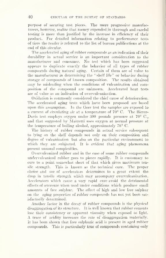
40 CIRCULAR OF THE BUREAU OF STANDARDS
purpose of securing test pieces. The more progressive manufac-turers, however, realize that money expended in thorough and careful
testing is more than justified by the increase in efficiency of their
product. For detailed information relating to performance tests
of tires the reader is referred to the list of bureau publications at the
end of this circular.
The accelerated aging of rubber compounds as an indication of their
durability in actual service is an important consideration to the
manufacturer and consumer. No test which has been suggested
appears to duplicate exactly the behavior of all types of rubber
compounds during natural aging. Certain of them are of value to
the manufacturer in determining the “ shelf life” or behavior during
storage of compounds of known composition. The results obtained
may be misleading when the conditions of vulcanization and com-position of the compound are unknown. Accelerated heat tests
are of value as an indication of overvulcanization.
Oxidation is commonly considered the chief cause of deterioration.
The accelerated aging tests which have been proposed are based
upon this assumption. In the Geer test the samples are exposed to
a current of circulating air at a temperature of 70° C. The Bierer-
Davis test employs oxygen under 300 pounds pressure at 70° C.,
and that suggested by Marzetti uses oxygen at normal pressure at
the temperature of boiling alcohol, approximately 78° C.
The history of rubber compounds in actual service subsequent
to lying on the shelf depends not only on their composition and
degree of vulcanization but also on the particular environment to
which they are subjected. It is evident that aging phenomenapresent unusual complexities.
Overvulcanized rubber and in the case of some rubber compoundsundervulcanized rubber goes to pieces rapidly. It is customary to
cure to a point somewhat short of that which gives maximum ten-
sile strength. This is known as the technical cure. The proper
choice and use of accelerators determines to a great extent the
drop in tensile strength which may accompany overvulcanization.
Accelerators which cause a very rapid cure avoid the detrimental
effects of overcure when used under conditions which produce small
amounts of free sulphur. The effect of high and low free sulphur
on the aging properties of rubber compounds has not yet been sat-
isfactorily determined.
Another factor in the decay of rubber compounds is the physical
disaggregation of its structure. It is well known that rubber cements
lose their consistency or apparent viscosity when exposed to light.
A trace of acidity increases the rate of disaggregation materially.
It has been shown that free sulphuric acid is present in aged rubber
compounds. This is particularly true of compounds containing only

TESTING OF RUBBER GOODS 41
rubber and sulphur and may account for the rapid deterioration of
such stocks. In general, an acid condition in rubber has a deleterious
effect on its aging characteristics and an alkaline condition is favor-
able to good aging properties. Practically all rubber compoundscontain accelerators and the presence of lead or zinc oxides, which are
basic, is necessary to activate most of them and cause them to function
properly. Consequently an alkaline condition is automatically
provided in the manufacture of rubber goods.
(a) COMPARISON OF NATURAL AND ACCELERATED AGING
For this comparison three compounds were chosen. CompoundNo. 1 has the following composition in percentage by volume :
Smoked sheet 83. 00
Sulphur 1. 47
Diphenylguanidine . 25
Zinc oxide . 55
Whiting 14. 73
Cured for 30 minutes at 287° F. (142° C.).
No. 2 compound is a tread compound and contains reclaimed rub-
ber and has the following composition in percentage by volume
:
Smoked sheet 60. 41
Hexamethylene-tetramine . 41
Sulphur 1. 74
Zinc oxide 1. 92
Gas black 10. 75
Mineral rubber 6. 03
Palm oil 3. 80
Reclaimed rubber 14. 94
Cured for 50 minutes at 294° F. (146° C.).
No. 3 compound is very similar in composition to the No. 1
compound except that in No. 3 an inorganic accelerator is used. Thecomposition in percentage by volume is as follows:
Smoked sheet 82. 45
Sulphur 2. 21
Litharge .80Whiting 14. 54
Cured for 15 minutes at 287° F. (142° C.).
Natural aging tests were made on the above stocks under varying
conditions as follows: Outdoor exposure on the roof where samples
were exposed to all atmospheric conditions, including sunlight. In-
door storage where samples were stored in the dark and aged at roomtemperature, approximately 75° F., for the same period of time as
those outdoors.
Accelerated tests were also made under three different conditions:
(a) Samples were exposed to a current of air at a temperature of
70° C., (b ) in an atmosphere of nitrogen at the same temperature,
and (c) in an atmosphere of oxygen at the same temperature.
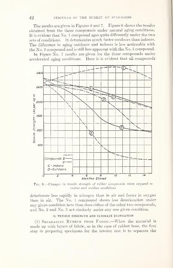
42 CIRCULAR OF THE BUREAU OF STANDARDS
The results are given in Figures 6 and 7. Figure 6 shows the results
obtained from the three compounds under natural aging conditions.
It is evident that No. 1 compound ages quite differently under the two
sets of conditions. It deteriorates much faster outdoors than indoors.
The difference in aging outdoors and indoors is less noticeable with
the No. 2 compound and is still less apparent with the No. 3 compound.
In Figure No. 7 results are given for the three compounds under
accelerated aging conditions. Here it is evident that all compounds
Fig. 6 .—Changes in tensile strength of rubber compounds when exposed to
indoor and outdoor conditions
deteriorate less rapidly in nitrogen than in air and faster in oxygen
than in air. The No. 1 compound shows less deterioration under
any given condition here than does either of the other two compounds,
and No. 2 and No. 3 act similarly under any one given condition.
(b) TENSILE STRENGTH AND ULTIMATE ELONGATION
(1) Separating Rubber from Fabric.—When the material is
made up with layers of fabric, as in the case of rubber hose, the first
step in preparing specimens for the tension test is to separate the

TESTING OF RUBBER GOODS 43
rubber from the fabric. Unless the frictioning is poor, this will
necessitate the use of a solvent. If there is more than one layer
of fabric, the easiest way is to remove the first layer along with the
rubber. The rubber is then separated from the adjoining layer of
fabric with the aid of gasoline blown from a wash bottle. Narrow
strips are more easily handled than larger pieces and there is less
danger of injuring the rubber. Great pains should be taken during
this operation, because any flaw or local imperfection will seriously
Fig. 7 .—Changes in tensile strength of rubber compounds in air,oxygen, and
nitrogen,at 70° C.
vitiate the results. The rubber should be allowed to rest for several
hours, in order that it may recover from the stretching it has received
and that the gasoline may thoroughly evaporate.
(2) Abrasive Machine for Buffing the Surface of Rubber.
—
The strips thus removed retain the impressions of the fabric from
which they have been separated, and it is necessary to grind the
surface smooth in order to measure accurately the thickness of the
test pieces. The abrasive wheel shown in Figure 8 was designed at
the bureau to accomplish this purpose and has proved very convenient

44 CIRCULAR OF THE BUREAU OF STANDARDS
and satisfactory. The rubber to be buffed is clamped, as shown, to a
circular sector which is rotated back and forth in front of a 5 by
134 inch emery wheel (No. 16), running at about 3,000 revolutions
per minute. An adjusting thumbscrew serves to advance the sector
by very small amounts as the buffing proceeds. The face of the
wheel should be dressed at intervals as may be required to maintain
a good abrasive surface.
(3) Form and Preparation of Test Pieces.—Test pieces are cut
with a metal die, which not only saves much time, but also insures
uniform width, which it is impossible to obtain if the specimens
Fig. 8 .—Abrasive wheel for grinding the surface of rubber test 'pieces to
produce a smooth surface
are cut by hand. An arbor press (fig. 9) is perhaps the most con-
venient and satisfactory means of forcing the die through the rubber,
although some prefer to cut the test pieces by striking the die with
a mallet. The operation is facilitated by wetting the rubber or the
cutting edges of the die, and the rubber should rest on a smooth
and slightly yielding surface which will not injure the cutting edges.
A piece of leather is suitable for the purpose. The central portion
of the test piece is straight, and the ends are gradually enlarged to
prevent tearing in the grips of the testing machine. The width of the
contracted section is usually made either one-fourth or one-half inch.
Figure 10 gives the dimensions of test pieces which have been found
to give satisfactory results. Figure 11 shows the various dies used at
this bureau. The one-fourth-inch test piece is to be preferred for
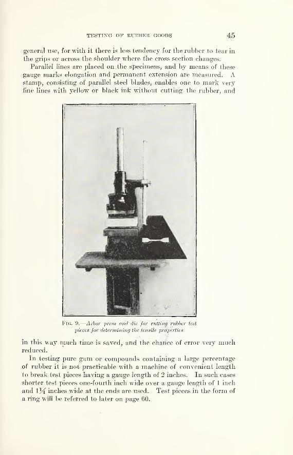
TESTING OF KUBBEK GOODS 45
general use, for with it there is less tendency for the rubber to tear in
the grips or across the shoulder where the cross section changes.
Parallel lines are placed on the specimens, and by means of these
gauge marks elongation and permanent extension are measured. Astamp, consisting of parallel steel blades, enables one to mark very
fine lines with yellow or black ink without cutting the rubber, and
Fig. 9 .—Arbor press and die for cutting rubber test
pieces for determining the tensile properties"
vV«».'•*
in this way much time is saved, and the chance of error very muchreduced.
In testing pure gum or compounds containing a large percentage
of rubber it is not practicable with a machine of convenient length
to break test pieces having a gauge length of 2 inches. In such cases
shorter test pieces one-fourth inch wide over a gauge length of 1 inch
and 134 inches wide at the ends are used. Test pieces in the form of
a ring will be referred to later on page 60.

46 CIRCULAR OF THE BUREAU OF STANDARDS
Fig. 11 .—Dies used for cutting test pieces

TESTING OF RUBBER GOODS 47
(4) Measuring the Thickness of Rubber.—A special form of
micrometer caliper (fig. 12, A) provided with enlarged contact sur-
faces and a ratchet stop is used to some extent for measuring the
thickness of rubber and textile materials. The ratchet stop makes
Fig. 12.
—
Instruments for measuring the thickness of rubber
A, micrometer; B, spring micrometer
Fig. 13 .—Grips used in making tensile tests of rubber
A, eccentric disks which tighten automatically as the tension increases; B, spools with ball bear-
ings for testing ring-shaped specimens; C, pivoted link grips for testing very soft stocks
it possible to measure each specimen under the same pressure andthus adds to the uniformity of results. A spring micrometer (fig.
12, B) is more generally employed for this purpose. It is exceedingly
convenient and very easily read.
48476°—27 4

48 CIRCULAR OF THE BUREAU OF STANDARDS
Fig. 14.
—
Motor-driven machine for test-
ing the tensile strength of rubber. See
Figures 15 and 16 for details
(5) Grips for HoldingTest Pieces.—In testing rub-
ber one of the greatest difficul-
ties has been to grip the test
piece in such a way as to pre-
vent slipping, without at the
same time injuring it. Evena very small scratch on tho
surface of a rubber test piece
may cause failure.
In order to prevent slipping
of the test piece as its section
is gradually reduced under in-
creasing tension, it has been
found advisable to provide
means for automatically tight-
ening the grip. This is conven-
iently accomplished by using
a number of thin cylindrical
disks, with knurled faces,
mounted eccentrically on a pin
(fig. 13, A), which act inde-
pendently, thus producing a
uniform pressure over the grip-
ping surface and preventing
any uneven slipping. The grips
shown in Figure 13, C, are es-
pecially well adapted for test-
ing soft rubber compounds hav-
ing a high rubber content.
When it is desired to test
specimens of circular form, such
as rubber bands, jar rings, or
washers, grips of the design
shown in Figure 13, B, maybe used. Each grip consists
of two rollers mounted on ball
bearings. The action of these
rollers is such that as tension
is applied they rotate in oppo-
site directions, thus tending to
equalize the stress around the
circumference of the test piece.
(6) Testing Machines.
—
The dynamometer 1 (fig. 14),
having a capacity of 125 poimds
and graduated to one-fourth

TESTING OF RUBBER GOODS 49
pound, is attached to the upper end of column 2,which is slotted to
receive the rack 3, carrying the eccentric grip 4 at its upper end. Themachine is operated by a one-twelfth horse-power motor, which is
belted to the stepped pulley 5 . A worm on the pulley shaft drives
a worm wheel which is geared to a spur (not shown) inside of column
2 . The eccentric grip 4 (fig. 15) is attached to the dynamometer
through pin connections 7 and 8 . The plate 9 serves to prevent
recoil of the springs when a specimen is broken, and acts in the
following manner: The rod 10,which is rigidly attached to column
2,passes with very little clearance through a hole in the back of
Fig. 15.—Detail of upper portion
of machine shown in Figure 14,
illustrating method of attaching
grip and device for preventing
recoil of spring
r
‘ ~
'
gj|
j
/6 ~ §13 jj
/3 - fiIhbI
Cfjf
S'
Sb™
- > i 71mUk 4. *—mil
Fig. 16.—Detail of lower portion of
machine shown in Figure 14, illus-
trating stepped pulley,gear drive
,and
releasing mechanism
plate 9 . The front of plate 9 is slotted to receive the rod 11,and is
supported by the shoulder 12 . As tension is applied to the specimen,
plate 9 is free to follow the shoulder 12,and passes down over the
rod 10,but when the specimen breaks the upward pressure of the
shoulder 12 causes the plate to bind on the rod 10,thus holding the
springs under the maximum tension. Hence the pointer of the
dynamometer remains at the maximum load when a specimen breaks.
The load having been recorded, the upper grip is pulled downward(by means of the hand wheel 13 and hooks 14 ,
if necessary, fig. 14)
to relieve the pressure of the shoulder 12 against plate 9,and at the

50 CIRCULAR OF THE BUREAU OF STANDARDS
same time the rear end of the plate is raised to release the rod 10 .
The tension of the springs may now be relieved- by allowing the grip
to rise, and the pointer is returned to zero.
At the end of a test the worm and gear are disengaged by means of
the spring clutch 15,
(fig. 16), and the rack is rapidly raised by hand
to its initial position.
The stepped pulleys provide for different speeds to meet the require-
ments of experimental work.
Elongation between gauge marks on the specimen may be measured
on the scale 16,attached to column 2
,but to do this requires the
services of two operators. A simpler and equally accurate methodis as follows: A wooden scale graduated to one-tenth inch, is held,
as shown in Figure 17, in a slightly inclined position at the back of
the test piece with its lower end pressed lightly against the rubber
just back of the lower gauge mark. As the rubber is stretched the
eye follows the scale just back of the upper gauge mark. With a
little practice the elongation at break can be measured with a fair
degree of accuracy.
The Schopper machine illustrated in Figure 18 is worked by hy-
draulic power, its operation, briefly stated, being as follows: Therubber test ring is placed over the spools, and the lower spool is
geared to the rack in such a way that it is caused to revolve during
a test. This motion is transmitted to the top spool by the rubber
test ring, the object of rotating the spools being to equalize the tension
at all parts of the specimen. As the tension is increased, the weighted
lever, to the short arm of which the top spool is attached, is gradually
deflected. When the test ring is broken, the lever is held at the point
of maximum load by means of a set of pawls. The breaking load
is then read from the curved scale and the elongation from the
vertical scale just opposite the test ring.
Figure 19 shows a motor-driven machine of 15 pounds’ capacity
which was designed for testing rubber bands. The load is applied
through the steel tape 1,at the end of which is the grip 2
,carrying
spools 4 , similar to those shown in Figure 13, B. The graduated steel
tape 3,attached to grip 2
,with its zero point coinciding with the
center of the spools 4 ,passes up behind the test specimen and through
the column 5 to a reel just behind the spring balance. When the
specimen breaks its elongation is determined by the distance betweenthe centers of the spools, as shown by the tape 3 . The plate 6 holds
the springs under the maximum tension at break in a way already
explained in connection with Figure 15. Stepped pulleys provide for
different speeds. When a specimen has been broken the worm andgear are disengaged by means of the lever 7, and the bottom spools
are raised by hand to their initial position. This machine is also
provided with eccentric grips which are used for testing straight
specimens of low tensile strength.

TESTING OF EUBBEE GOODS 51
Fig. 18 .—
“
Schopper” machine for
testing the tensile strength of rub-
ber. This machine operates on
the principle of a weighted lever
Fig. 17 .—Illustrating method of
measuring ultimate elongation
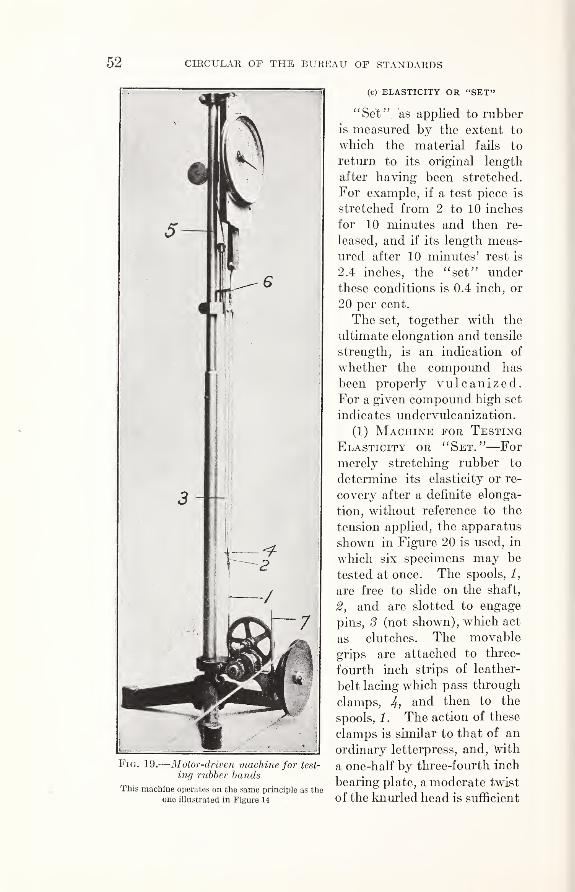
52 CIRCULAR OF THE BUREAU OF STANDARDS
(c) ELASTICITY OR “SET”
Fig. 19.
—
Motor-driven machine for test-
ing rubber bands
This machine operates on the same principle as the
one illustrated in Figure 14
“Set” as applied to rubber
is measured by the extent to
which the material fails to
return to its original length
after having been stretched.
For example, if a test piece is
stretched from 2 to 10 inches
for 10 minutes and then re-
leased, and if its length meas-
ured after 10 minutes’ rest is
2.4 inches, the “set” under
these conditions is 0.4 inch, or
20 per cent.
The set, together with the
ultimate elongation and tensile
strength, is an indication of
whether the compound has
been properly vulcanized.For a given compound high set
indicates undervulcanization.
(1) Machine for Testing
Elasticity or “Set.”—For
merely stretching rubber to
determine its elasticity or re-
covery after a definite elonga-
tion, without reference to the
tension applied, the apparatus
shown in Figure 20 is used, in
which six specimens may be
tested at once. The spools, 1,
are free to slide on the shaft,
2,and are slotted to engage
pins, 3 (not shown), which act
as clutches. The movable
grips are attached to three-
fourth inch strips of leather-
belt lacing which pass through
clamps, 4 ,and then to the
spools, 1 . The action of these
clamps is similar to that of an
ordinary letterpress, and, \vith
a one-half by three-fourth inch
bearing plate, a moderate twist
of the knurled head is sufficient

TESTING OF RUBBER GOODS 53
to prevent any slip of the belt lacing when under tension. Theoperation of the apparatus is as follows:
The specimens being in the grips, one of the spools is movedalong the shaft until it engages the corresponding pin, and the
shaft is revolved until the desired elongation measured between
gauge marks on the specimen is secured. The clamp is tightened
to hold the specimen in this position, and the spool is shifted back
so as to disengage the pin. The operation is repeated with each
Fig. 20 .—Apparatus for stretching rubber to determine its elasticity
of the specimens in turn. Each specimen is released after a specified
length of time (usually 1 or 10 minutes), and after an equal interval of
rest the permanent extension or set is measured with a scale graduated
to 0.01 inch.
<d) REDUCTION IN TENSION WHEN RUBBER IS HELD AT A DEFINITE ELONGATION
When rubber is stretched in a testing machine the extension
gradually increases with the applied tension, as is the case with other
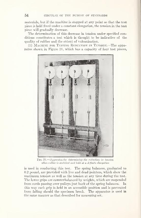
54 CIRCULAR OF THE BUREAU OF STANDARDS
materials, but if the machine is stopped at any point so that the test
piece is held fixed under a constant elongation, the tension in the test
piece will gradually decrease.
The determination of this decrease in tension under specified con-
ditions constitutes a test which is thought to be indicative of the
quality of rubber and the extent of vulcanization.
(1) Machine for Testing Reduction in Tension.—The appa-
ratus shown in Figure 21, which has a capacity of four test pieces,
Fig. 21 .—Apparatus for determining the reduction in tension
when rubber is stretched and held at a definite elongation
is used in conducting this test. The spring balances, graduated to
0.2 pound, are provided with live and dead pointers, which show the
maximum tension as well as the tension at any time during the test.
The lower grips are counterbalanced by weights, which are suspended
from cords passing over pulleys just back of the spring balances. In
this way each grip is held in an accessible position and is prevented
from falling should the specimen break. The apparatus is used in
the same manner as that described for measuring set.

TESTING OF RUBBER GOODS 55
(e) CONDITIONS AFFECTING THE RESULTS OF TENSION TESTS
In the absence of uniform methods of testing, it is found that results
obtained in different laboratories sometimes show marked discrep-;
ancies which are due to the varying conditions under which the tests
are made.
(1) Influence of Speed on Tensile Strength and UltimateElongation.—The speed at which rubber is stretched probably
affects the results to a less extent than is often supposed, though
doubtless different rubbers are not equally affected.
Table 2 shows the results obtained in a comparative test of four
compounds.
Table 2.—-Tensile strength and ultimate elongation as affected by rate of stretching
[Gauge length=2 inches]
Compound Rate of
stretchTensilestrength
Ultimateelongation
In./min. Lbs./in. 2 Per cent
f5 2, 495 605
G-18 -- f 25 2, 690 635
1 45 2,720 635
[5 1,900 465
M-l 1 25 1, 940 500{ 45 1, 970 490
\5 375 340
B-l \ 25 430 360l 45 465 375
1
5 340 105Gy-1 < 25 390 115
[ 45 430 120
These results would seem to indicate a general tendency toward
higher values for both tensile strength and ultimate elongation as the
speed of stretching increases.
(2) Influence of Temperature on Strength, Elongation,and Elasticity.—It is generally recognized that the physical proper-
ties of rubber are affected by changes in temperature, though, of
course, to a less extent after vulcanization than before.
Figure 22 shows the results of tests at 50, 70, and 90° F. In each
case the room was maintained at the specified temperature for three
hours before the tests were made. It will be noticed that the rubbers
are not all affected to the same extent by equal differences in tempera-
ture, but that there is a marked tendency in each case toward
decreased strength, decreased set (increased elasticity), and increased
elongations as the temperature is raised. It will be noted further
that in nearly every case greater differences occur between 50 and 70°
than between 70 and 90°.
The set in each case was measured after one-minute stretch andone-minute rest. Nos. 1 and 2 were stretched 350 per cent, Nos.
3 and 4, 300 per cent, and No. 6, 250 per cent.

56 CIRCULAR OF THE BUREAU OF STANDARDS
(3) Influence of Cross Section on Tensile Strength and
Ultimate Elongation.—Tensile strength and ultimate elongation
are theoretically independent of sectional area, but, as in other mate-
rials, there is a tendency for small test pieces of rubber to develop
higher unit values than large ones. Complete data on this subject
are not at hand, but it is thought that test pieces one-fourth and one-
3000
2800
2600
2400
2200
2000
1800
1600 3I
Il—
1400 &
1200 co
id
co1000 z
UJH
800
600
400
200
TEMPERATURE
Fig. 22 .—Chart showing influence of temperature on the elasticity, tensile
strength, and ultimate elongation of rubber
half inch wide will show, in general, but little difference in ultimate
elongation, but an appreciable difference in tensile strength, in the
case of high-grade compounds.
Comparative results obtained with test pieces one-fourth and
one-half inch wide are shown in Table 3. These rubbers represent
commercial compounds. The test pieces were cut from the tubes
and covers of plied hose, and the impression left by the fabric was
carefully removed with an abrasive wheel.

TESTING OF RUBBER GOODS 57
Table 3.—Influence of cross section upon the tensile strength and ultimate
elongation of rubber
Compound
M-4 cover.
M-3 tube..
G-19 tube.
G-19 cover.
M-5 tube..
Width ofspecimen
Tensilestrength
Ultimateelonga-tion
Inch Lbs./in. 2 Per cent
/ X 1, 565 525
t Vi 1, 455 515
/ X 2,160 580
X Vi 1, 955 570
/ X 1, 025 350
\ Vi 955 340
f X 735 255
\ >4 690 250
/ 2,490 615
l ^ 2,060 575
Table 4.—Influence of direction in which specimens are cut on tensile properties
Sample No.
1.
2 .
3.
4.
6 .
6 .
(Longitudinal./Transverse. ..
/Longitudinal./Transverse. ..
/Longitudinal./Transverse...
/Longitudinal./Transverse. ..
Longitudinal.Transverse. ..
/Longitudinal./Transverse. ..
DirectionTensilestrength 1
Ultimateelonga-tion
Set 1 after
300 percent elon-gation for
1 minutewith 1
minuterest
Lbs./in.2 Per cent Per cent
2,730 630 11.2
2, 575 640 7.3
2, 070 640 6.0
2, 030 670 5.0
1, 200 480 22.1
1,260 555 16.3
1, 850 410 34.01,700 460 24.0
690 320510 280
880 315 34.3690 315 25.9
1 The set and tensile strength were determined with different test pieces.
(4) Influence of the Direction in which Specimens areCut on Strength, Elongation, and Elasticity.—The tensile
properties of sheet rubber are not the same in all directions, as will be
shown later in connection with comparative tests of straight and
ring-shaped test pieces. There is a tendency for specimens cut
longitudinally, or in the direction in which the rubber has passed
through the calender, to show greater strength and (at least for the
better grades of compounds) less elongation than specimens cut
transversely or across the sheet. The recovery, however, is greater
in the transverse direction. Table 4 illustrates this.
No. 3 shows slightly greater strength transversely and No. 5
greater elongation longitudinally, while No. 6 shows the sameelongation in each direction. The exception noted in No. 3 is
attributed to experimental errors or to small defects in the specimens
which escaped detection. It may be, however, that low-grade rub-
bers, such as Nos. 5 and 6, are not more extensible transversely than
longitudinally.

58 CIRCULAR OF THE BUREAU OF STANDARDS
(5) Influence of “Backing” on the Tensile Strength andElasticity of Hose Lining.—In the case- of -cotton rubber-lined
hose the “backing” which is used to cement the lining to the fabric,
if not removed, affects to a greater or less extent the values obtained
for tensile strength and elasticity or “set.”
If the backing has an ultimate elongation greater than that of
the lining, it must necessarily increase the tensile strength which
is figured from the breaking load and the measured cross section of
the rubber lining. The observed value for “set” which is obtained
as described on page 52, is greater or less than the true value, according
as the lining is more or less elastic than the backing. If the elasticity
of the backing differs very much from that of the lining, it will be
found that the broken test pieces have a tendency to curl up like a
watch spring, with the backing on the inside or outside according
as its elasticity is greater or less than that of the lining. It is cus-
tomary to test hose linings with the backing removed.
In Table 5 are recorded the results of tests that were made to
determine the effect of backing on the tensile properties of hose
linings. For these tests the backing was removed with an abrasive
wheel. Differences in the values of tensile strength in A and Bmay be attributed partly to errors in measuring the thickness of
the specimens that were tested without removing the backing. In
the case of No. 1, however, it is thought that the thickness wasdetermined without appreciable error. The adhesion between tube
and backing being weak, it was possible to separate the two byhand, and the eight specimens thus secured showed a maximumvariation in thickness of only O' '.003. The average thickness wasused in computing the strength of specimens tested with backing
(A). It is seen that in this case the backing very materially increased
the strength of the test pieces.
Table 5.—Effect of backing on the tensile properties of fire-hose linings
Sample 1 SetTensilestrength
Ultimateelonga-tion
1, APer cent
2 24. 5
Lbs./in.2
3,0802,5353, 015
2, 790
Per cent590
1, B. 2 23.0 575
2, A 2 17. 5 6252, B 2 18. 5 635
3, A 2 17. 5 3, 0252,615
2, 7052,720
2,7952, 3002,5552,410
2,0952,3351, 190
6453, B 2 19. 0 6104, A 2 20. 5 6504, B 2 19.0 645
5, A 2 24. 0 5805, B 2 23. 5 5856, A 3 20. 5 5356, B 3 22. 5 540
7, A 2 21. 0 5507, B 2 17. 5 590
8, A 3 21. 5 5358, B 3 20.5 1, 190 535
1 A, tested without removing backing; B, tested with backing removed.2 Measured after 400 per cent elongation for 10 minutes, with 10 minutes’ rest.3 Measured after 350 per cent elongation for 10 minutes, with 10 minutes’ rest.

TESTING OF RUBBER GOODS 59
(6) Influence of Previous Stretching on Strength, Elonga-tion and Elasticity.—Test pieces that have been used to deter-
mine set usually show greater strength and ultimate elongation than
are obtained with test pieces that have not been previously stretched.
Table 6.—Influence of repeated stretch on tensile strength and ultimate elongation
Sample No.
Tensile strength Ultimate elongation
Singlestretch
Repeatedstretch
Singlestretch
Repeatedstretch
1
Lbs./in.2,4701, 740990
1,710750930
Lbs. /in.
2, 6101,9601, 1801,790
790920
Per cent645665510460430375
Per cent765780645555440465
23456
Table 6 gives the strength and ultimate elongation obtained
in testing six samples of rubber, first, with a single stretch, andsecond, by repeated stretching, beginning with 200 per cent andincreasing each stretch by 100 per cent until failure.
In testing rubber as described above, it is found that if during
the latter part of the test the increments in extension for successive
stretches are small (say, 25 per cent of the original length), a point
is reached where the rubber breaks down, and beyond which it
fails on a subsequent stretch at a tension less than the maximumwhich it has already withstood.
The elasticity or set after a definite elongation is usually greater
if the rubber has been previously stretched than if determined in the
usual way. This is illustrated by the results shown in Table 7; those
marked “ Repeated stretch” show the set after repeated stretching,
beginning with 100 per cent and increasing 100 per cent for each
subsequent stretch. Those marked “ Single stretch” were obtained
in the usual way, each specimen being stretched but once. In each
case the set was measured from the original gauge marks after
one-minute stretch and one-minute rest, the tabulated results being
the average of the values obtained in ttesting a number of specimens.
Table 7.—Influence of repeated stretch on the elasticity of rubber
Sam-pleNo.
Method of testing
Set (in per cent) after being stretched
—
100 percent
200 percent
300 percent
400 percent
500 percent
1(Repeated stretch ... . . 1.0 4. 5 9. 5 16. 0 25.0(Single stretch. . 11. 7 19.8 29. 0
o (Repeated stretch .. . 1.8 4.0 7. 7 13. 7 21. 2(Single stretch . 8. 0 14. 7 21. 5
3(Repeated stretch .. ._ 3.7 9.0 17. 7 27.0 37.0(Single stretch. ..... .... 21. 7 34. 0 47.0
4(Repeated stretch.. . . ...... ...... 4.0 12.3 28. 7 48. 7(Single stretch. ..... 14. 3 33. 0 56.0
(Repeated stretch . _ .. .... 8.
1
19.4 34. 05(Single stretch 19. 3 33. 0
(Repeated stretch.. . 4.3 16.3 34. 06(Single stretch ... ... . 17.0 35.3

60 CIRCULAR OF THE BUREAU OF STANDARDS
It will be noted that the effect of previous stretching is very
marked in the case of Nos. 1, 3, and 4; that it is very slight in the
case of Nos. 2 and 6; and that in the case of No. 5 the set is slightly
increased by previous stretching.
(7) Influence of the Form of Test Piece on the Results of
Tension Tests.—There is a wide difference of opinion in regard to
the relative merits of the straight and ring-shaped test pieces. Thering, which is highly recommended by some, undoubtedly possesses
certain advantages as regards convenience in testing, and uniform
results may be obtained with this form of test piece.
Ring test pieces, however, do not show the full tensile strength of
rubber, on account of the uneven distribution of stress over the cross
BEFORE STRETCHING
AFTER STRETCHING
Fig. 23 .—Ring test 'piece before and after being stretched
section. This fact is evident from a simple analysis, and may be
verified by comparative tests with straight and ring-shaped test
pieces, provided the straight test pieces are sufficiently enlarged at
the ends to prevent failure in the grips, and provided further that
the change in width is not made too abruptly.
Assuming for simplicity that the extensibility of rubber is the samein all directions, it will be seen by reference to Figure 23, which
represents a ring test piece before and after extension, that,
If E1= per cent elongation of the inside surface at breaking point
(automatically measured), then
Ei=K— • 100h
(i)
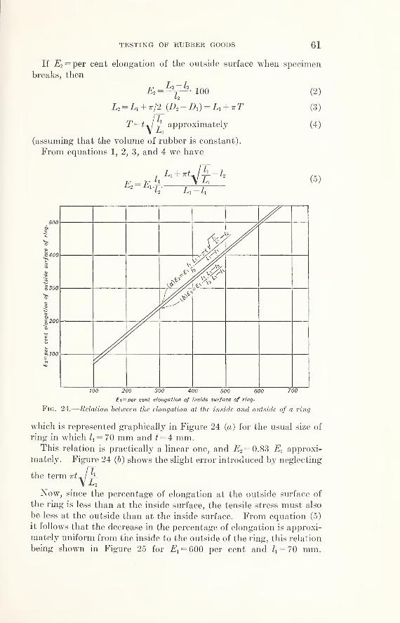
TESTING OF RUBBER GOODS 61
If jE^per cent elongation of the outside surface when specimen
breaks, then
e2 = 100
L2 = Li + 7r/2 {D2 —D\ )= L\ + 7rT
approximately
(assuming that the volume of rubber is constant).
From equations 1, 2, 3, and 4 we have
E2 =E1
1
y-l2
i, 4" Trt^ I J /
(2 )
(3 )
(4 )
(5 )
U-l:
100 200 300 400 500 600 700
Et=per cent elongation of inside surface of ring.
Fig. 24 .—Relation between the elongation at the inside and outside of a ring
which is represented graphically in Figure 24 (a) for the usual size of
ring in which ll = 70 mm and t = 4 mm.This relation is practically a linear one, and E2 = 0.83 El approxi-
mately. Figure 24 (6) shows the slight error introduced by neglecting
the term irt^ h-V£
Now, since the percentage of elongation at the outside surface of
the ring is less than at the inside surface, the tensile stress must also
be less at the outside than at the inside surface. From equation (5)
it follows that the decrease in the percentage of elongation is approxi-
mately uniform from the inside to the outside of the ring, this relation
being shown in Figure 25 for Ei = 600 per cent and Zx = 70 mm.

62 CIRCULAR OF THE BUREAU OF STANDARDS
The relation between stress and elongation being practically a linear
one for values of elongation near the breaking point, the decrease in
tensile stress must also be fairly uniform from the inside to the out-
side of the ring at the time of failure. This is illustrated graphically
in Figure 25, in which the values for tensile stress were taken from
the stress-strain diagram shown in Figure 26, No. 1.
0 y2 1 Vi 2 3 4
t= distance from jnside surface in mmFig. 25 .— Variation in elongation and tensile strength from the inside
to the outside of a ring
If = the stress at the inside surface of the ring at failure, or true
tensile strength of the rubber corresponding to Ei} and $2= the stress
at the outside surface, corresponding to E2 ,and S = the average stress
over the cross section of the ring, which is the value for tensile strength
obtained by the ring method, we have
S=Breaking load_ffi + ff2
Area of section 2
Si
2+ approximately. (6)

STRESS
—
LBS.
PER
SQ.
IN.
STRESS—
LBS.
PER
SQ.
IN.
50 100 150 200 250 300 350 400 450 500 550 600 6500 50 100 150 200 250 300 350 400 450 500 550 600 650 700
ELONGATION—PER CENT.Fig. 26. Stress-strain curves for rubber tested with straight and ring-shaped specimens48476°—27 5 68

64 CIRCULAR OF THE BUREAU OF STANDARDS
sNow, since the ratio varies for different rubbers, S does not
Ol
bear a constant ratio to, and, therefore, can not be taken as a meas-
ure of tensile strength. Elongation, however, is measured at the
inside surface of the ring and, therefore, represents the maximumextension of the rubber around the inside of the ring. The average
elongation over the cross section of the ring is,
2?= 1/2 (Ei +
E
2 ) approximately. (7)
If the extensibility of rubber were the same in all directions, values
of S and E obtained from equations (6) and (7) would, theoretically,
give a point lying very near the stress-strain curve for the samerubber tested in the form of a straight specimen. This, however, is
not the case, as has been already pointed out, and as may be seen
from Figure 26.
The difference between S and Si is greater for high-grade rubbers
than for compounds of poor quality, as may be seen by reference to
Figure 26, which represents stress-strain curves plotted from the
results of tests on straight and ring specimens. Table 8 shows
values for tensile strength and ultimate elongation obtained for the
same rubbers by the two methods.
The ring test piece obviously does not give a true stress-strain
curve on account of the varying stress over its cross section.
Table 8.—Relative tensile strength and elongation of rubber tested with straight andring-shaped specimens
Specimens
Tensile strength, in pounds per square inch, forrubber compounds Nos. 1 to 6
1 2 3 4 5 6
Straight specimens:Longitudinal (L) i_ 2, 730 2, 070
2, 0301,200 1,850 690 880
Transverse (T) _ 2,575 1,260 1,700 510 690Ring specimens (R) 2, 140 1,690 1,060 1,520 510 730
R/L .78 .82 .88 .82 .74 .83R/T .83 .83 .84 .89 1. 00 1.06
Ultimate elongation, in per cent
Straight specimens:Longitudinal 630 640 480 410 320 315Transverse 1 640 670 555 460 280 315
Ring specimens ... 635 675 525 435 285 320
1 Longitudinal indicates the direction in which the rubber has been passed through the calender rolls.
Straight specimens were cut both longitudinally and transversely,
with reference to the direction in which the rubber had been passed
through the calender rolls. They were tested with the machine
shown in Figure 14, and the ring specimens were tested with the
machine shown in Figure 18. In each case the specimens were
stretched at the rate of about 8 inches per minute. A number of

TESTING OF RUBBER GOODS 65
test pieces, both straight and ring-shaped, showed, particularly in the
case of No. 3, abnormally low tensile strength and elongation on
account of small holes or particles of grit at the point of rupture.
Such specimens are not included in the results tabulated above,
each of which represents the average of from 5 to 15 tests.
A line was drawn across each of the ring specimens to indicate the
longitudinal direction, and the point of failure was noted. There
was a tendency for the rings to rupture along this line, thus indicating
that the sheets were strongest longitudinally, or in the direction of
rolling. This difference in strength is shown b}T the straight test
pieces, except in the case of compound No. 3. It is seen from Figure
26 that the curve for transverse specimens lies below that for longi-
tudinal specimens, thus showing that a given stress will produce a
greater elongation if applied transversely than if applied longitudi-
nally. It is to be expected, therefore, that the elongation of a ring
will be less than that for a transverse straight specimen. The natural
variation in rubber, however, is often sufficient to obscure small
differences in elongation, which are due to the methods of testing.
In the case of Nos. 5 and 6, the curves for the ring specimens
almost coincide with those for the transverse straight specimens,
and the tensile strengths of these rubbers when tested by the two
methods are seen to agree fairly well. It is to be noted, however,
that for the higher-grade rubbers the difference in tensile strength
by the two methods is very marked. Although the difference is not
great, there is a tendency for the transverse specimens to show a
greater ultimate elongation than the longitudinal specimens, not-
withstanding the greater stength shown in the latter case.
(/) “FRICTION” TEST
The “friction” or adhesion between the plies of fabric, or between
the fabric and rubber parts, is of great importance; in fact, the life of
pneumatic tires, belting, hose, etc., depends in a great measure upon
the efficiency of this adhesion. For a description of detailed test
methods see Bureau Circular No. 232.
Friction is preferably determined autographic ally with the machine
illustrated in Figure 27, which records the tension required to cause
a definite rate of separation between the two parts considered.
The machine is operated by a one-eighth-horsepower worm-geared
shunt motor which is belted to a stepped pulley. A worm on the
pulley shaft drives a worm wheel which is geared to a spur inside of
the vertical steel column. This spur drives a steel rack, to the
upper end of which is attached the movable grip. From the top of
the machine is suspended a spring which carries at its lower end a
fork or suitable grip for holding the test piece. Between the spring
and fork is a pencil holder, in front of which is a drum carrying a
paper chart on which the record is drawn.

66 CIRCULAR OF THE BUREAU OF STANDARDS
Fig. 27.—Autographic friction
machine for measuring and re-
cording the adhesion between
;
plies of fabric
The machine is constructed so that
a spring suitable for the grade of ma-terial being tested can be used in it.
The drum is driven by a cord which
passes over a small guide pulley andthence to a spool on the spur-gear
shaft. The surface speed of the drumis the same as the rate of separation
of the plies of fabric being tested.
In the case of rubber hose a 1-inch
section is fitted over a mandrel and
placed in the fork suspended from the
top of the machine, and the detached
end of the fabric is secured to the
lower grip as shown.
In the case of rubber belting a
strip 1 inch wide containing two plies
is used. The plies are separated for
a short distance and the ends secured
in the two grips, the upper grip being
a clamp held in the fork above men-tioned.
The method formerly used, but
which is rapidly going out of use, is
illustrated in Figure 28 and consists in
measuring the rate of separation pro-
duced by the action of a dead weight.
The results of this test are in-
fluenced by the temperature condi-
tions, the rate of stripping caused bya given weight being greater at high
than at low temperatures. Also, the
rate of stripping is greater if the
mandrel fits snugly in the ring than
if the ring is allowed to sag over a
loose mandrel. The variation in fric-
tion, however, in the same hose is
often such as to obscure these influ-
ences, unless observations are madeunder conditions which differ greatly.
In connection with this test, atten-
tion may be called to a point which,
though generally recognized, is some-
times lost sight of in the interpreta-
tion of results.
It has been observed that no
stripping is produced by increasing
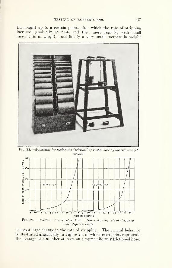
TESTING OF RUBBER GOODS 67
the weight up to a certain point, after which the rate of strippingincreases gradually at first, and then more rapidly, with smallincrements in weight, until finally a very small increase in weight
Fig. 28.—Apparatus for testing the “friction” of rubber hose by the dead-weight
method
Fig. 29.—“Friction” test of rubber hose. Curves showing rate of stripping
under different loads
causes a large change in the rate of stripping. The general behavioris illustrated graphically in Figure 29, in which each point represents
the average of a number of tests on a very uniformly frictioned hose.
68 CIRCULAR OF THE BUREAU OF STANDARDS
As a result of this behavior, an air hose, for example, which is
required to show a rate of stripping not exceeding 6 inches in 10
minutes under 25 pounds, might be regarded as of very inferior
quality if it stripped, say, 20 inches in 10 minutes, whereas the
same hose would probably show little or no stripping under 20
pounds and come within the required limit under 22 pounds.
In testing fire hose, the central portion of the lining is separated
from the jacket for a short distance at one end. The detached
end of the jacket is clamped in a stationary grip, and the weight
is suspended from the rubber lining.
The “ friction” between the plies of duck in rubber belting is
sometimes tested by applying the load in a direction at right angles
to the plane of separation, as in the case of “ plied” hose. As shown
in Figure 30, A, this is done by cutting the belt about halfway through
along parallel lines 1 inch apart. The belt rests on horizontal sup-
ports just outside of the strip which has been cut, and the weight is
suspended from the detached end of the duck. Figure 30, B, illus-
trates a method by which a 1-inch strip is held in a fixed clamp with
the weight suspended from the end of a detached layer of duck.
In testing by this method it will be found that the angle of separation
varies somewhat according to the thickness of the strip and that the
results are thereby influenced to some extent. The difficulty maybe avoided by subdividing the 1-inch section into strips of two
plies each, as shown in Figure 30, C, and very satisfactory results
are obtained in this way. It is found that for a given weight the
rate of stripping is decidedly greater by methods B and C than bymethod A. Figure 31 shows graphically the results obtained by the
three methods.
A marked difference is often found in the friction between different
plies of the same hose, or other articles of plied construction, as well
as at different points along the same ply. Uniformity in the friction
is desirable.
(g) HYDRAULIC-PRESSURE TEST
The pressure test as usually made consists simply in subjecting the
hose to water pressure created by a force pump of any convenient
type. The coupling at the free end is closed with a plug, and the
pump connection is made with a reducing coupling. By using twoclamps at each end it is possible to make a joint which is tight evenunder high pressure. It is necessary to provide a check valve to
protect the pressure gauge against shock when a hose bursts. Apet cock must be provided to release the air as the hose is being filled.
Requirements of specifications as regards the pressure test vary
according to the kind of hose, but, as a rule, the test is made not with
the view of developing the ultimate strength of the hose but rather
to detect defects in workmanship, which are usually noticeable at a
pressure well below that necessary to rupture the hose.

TESTING OF RIJBBEE GOODS 69
Fig. 31 .—Friction test of rubber belting
Curves showing rate of stripping when tested by the methods illustrated in Figure 30

70 CIRCULAR OF THE BUREAU OF STANDARDSi
In the case of fire hose it is usual to specify a certain pressure
when the hose is lying straight or when bent to the arc of a circle
of given radius, and the hose must stand a specified pressure whendoubled upon itself. A full 50-foot length must not show excessive
expansion, elongation, warping, or twist under pressure, and anytwist must be in a direction tending to tighten the couplings.
(h) STEAMING TEST
Fig. 32 .—Six samples of steam hose
connected up for steaming test
(i) TESTING THE RUBBER INSULATION OFWIRE
The mechanical tests that are
usually specified for the rubber insu-
lation of wire are the same as those
already described in connection
with tension tests.
The method of preparing test
pieces, however, is not always the
same, but depends upon the size of
the conductor and the character of
the insulation. (See Federal Specifi-
cations Board Specification No. 59,
Bureau of Standards Circular No.
232.)
(j)
COMPARATIVE TESTS OF MACHINE AND HANDMADE TUBES
A question is sometimes raised as to whether the tube of a hose
has been made in a tubing machine or from calendered sheet.
Calendered tubes are often specified, and since it is sometimes
impossible to determine by inspection if a tube is machinemade or
handmade, a test that could be depended upon in all cases to dis-
tinguish between the two kinds of tubes would serve a useful purpose.
From the nature of the case a chemical analysis could not deter-
mine this point, because a compound might be calendered or run
Figure 32 illustrates a method of testing steam hose. The header 1
is provided with six outlets, each of which is controlled by a one-half
inch globe valve. The header 2,
which is connected to a steam trap
3, is similarly provided with inlets
and controlling valves. The hose
to be tested is cut into lengths that
will just fit between the connections
on the headers, the bottom con-
nections being made with unions.
Steam passes through a regulating
valve (not shown) into the header 1
and thence through the hose to the
header 2,from which the condensa-
tion is carried to the steam trap.
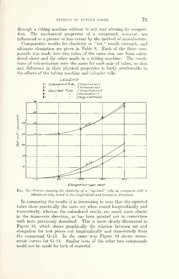
TESTING OF RUBBER GOODS 71
through a tubing machine without in any way altering its composi-
tion. The mechanical properties of a compound, however, are
influenced to a greater or less extent by the method of manufacture.
Comparative results for elasticity or “set,” tensile strength, andultimate elongation are given in Table 9. Each of the three com-pounds was made into two tubes of the same size, one from calen-
dered sheet and the other made in a tubing machine. The condi-
tions of vulcanization were the same for each pair of tubes, so that
any difference in their physical properties is fairly attributable to
the effects of the tubing machine and calender rolls.
L£G£1/VDO- Co/encf&rTsd Tube. (/or>g/+udwo/
/
<J>"
* ( f/'&/7.S'Ves'S<3J• “ Scpu/rf&cf Tube C/<=>^^fbac/f/7cr/)
- Ty’naos-tfgr&g
)
- (/ongcmcff-rarTs)
SAb/ij&T/on -/oes- cenf
Fig. 33 .—Curves showing the elasticity of a 11squirted" tube as compared with a
calendered tube, tested in the longitudinal and transverse directions
In comparing the results it is interesting to note that the squirted
tubes show practically the same set when tested longitudinally andtransversely, whereas the calendered stocks are much more elastic
in the transverse direction, as has been pointed out in connection
with tests previously described. This is more clearly illustrated in
Figure 33, which shows graphically the relation between set and
elongation for test pieces cut longitudinally and transversely fromthe compound G-13. In the same way Figure 34 shows stress-
strain curves for G-13. Similar tests of the other two compoundscould not be made for lack of material.

72 CIRCULAR OF THE BUREAU OF STANDARDS
Table 9.—Relative tensile properties of “squirted” and calendered tubes whentested in the longitudinal and transverse directions
Sample No. Method of manufacture
Set 1 after one-min-ute stretch and one-
minute rest
Tensile strength Ultimate elongation
Longi-tudinal
Trans-verse
Longi-tudinal
Trans-verse
Longi-tudinal
Trans-verse
V-14 fCalendered . .
Per cent11. 7
Per cent
10. 5
Lbs. jin.
520Lbs./in.
530Per cent
275Per cent
290\Squirted 12. 5 12. 5 460 460 240 235
V-16 fCalendered--- . . 24. 7 20. 0 1, 450 1, 380 530 535\Squirted 23. 0 21. 8 1, 310 1, 290 525 505
G-13fCalendered... . 26.0 18. 5 1, 110 1, 295 455 510\Squirted _ 22. 5 21. 5 1, 130 1, 330 470 510
i y_i4 was stretched 200 per cent; V-16 and G-13, 350 per cent.
£/on<g&-f/o/7 ~ cz&n/
Fig. 34.—Stress-strain curves for a “squirted” and a calendered tube tested in the
longitudinal and transverse directions

TESTING OF RUBBER GOODS 73
(k) TESTING OF RUBBER BANDS
(1) Under One-fourth Inch in Width.—In the testing of
rubber bands a different method is employed from that used in the
testing of other types of rubber goods. Owing to the size of the
specimens, it is impracticable to obtain accurately the cross-sectional
area, consequently the tensile strength is not computed in pounds
per square inch, as is customary in other goods.
Double-spool grips similar to the grips illustrated in Figure 13, B,
but smaller, are used. The test machine used for this work is
shown in Figure 19, and a description may be found on page 50.
Tensile strength and ultimate elongation .—The tensile strength is
measured in pounds and the elongation is expressed in percentage of
the original length.
Ultimate elongation, per cent =(L-LJ 100
Li
where
Z = one half the distance around spools at time of failure.
Li = initial inside length of band, measured flat (one-half total
length)
.
(2) Bands One-fourth Inch in Width or Over.—The testing of
bands one-fourth inch or more in width requires the use of the grips
shown in Figure 13, B, and the tests are made on the machine usually
employed for determining the tensile strength of rubber (fig. 14).
Tensile strength and ultimate elongation .—In bands of this size it is
practicable to measure the width and thickness. The tensile strength
is calculated in pounds per square inch as follows:
Tensile strength in pounds per square inch =
where
B = breaking load in pounds.
w = width of band in inches.
t= thickness of band in inches.
Elongation is measured and expressed in the same way as described
above for bands under one-fourth inch in width.
Jar rings are tested in the same way as rubber bands. Owing to
the shape of the material, the internal length Lx becomes one-half
the internal circumference, thus:
where
I) = internal diameter in inches.
(1) ABRASIVE RESISTANCE OF RUBBER COMPOUNDS
A great deal of work has been done in the past few years in an
attempt to develop laboratory machines which would measure
accurately the resistance to abrasion of a rubber compound. Many

74 CIRCULAR OF THE BUREAU OF STANDARDS
different types have been tried, several of which when used to com-
pare stocks of similar compositions give a good measure of the rela-
tive resistance to abrasion. In spite of the large amount of work
done, however, there is no machine which has been generally accepted
as a standard.
Some of the different types which have been developed are illus-
trated in Figure 35.
These machines may be briefly described as follows:
Machine G .—Samples 1 inch square and one-fourth inch thick are
secured to a weighted arm and pressed against the face of an abrasive
wheel 6 inches in diameter, which is surfaced with garnet paper.

TESTING OF RUBBER GOODS 75
Machine Hr—Twelve samples each 2 by 3^ inches by J4 inch
are fastened around the circumference of a flat-faced wheel approxi-
mately 15 inches in diameter. This wheel rests upon the surface
of a carborundum disk the axis of which is at right angles to that of
the wheel, and thus the wheel and disk constitute a friction drive
by means of which the samples drive the abrasive disk against a
constant resistance produced by a friction brake.
Machine I.
5
—This machine consists essentially of a revolving
table 30 inches in diameter, the surface of which is composed of
crushed feldspar held in place with Portland cement. The samples
2 by 5 inches by 34 inch are held in grips which are swivelled so that
they move under their weight. The samples bear against the sur-
face of the table and are abraded as the table revolves.
Machine J .—In this test a complete tire is used. It is mountedon a rim, inflated, and pressed against the face of a carborundumwheel. The tire and the abrasive wheel are driven in the samedirection where in contact, but at different speeds. The tire is run
until the tread wears through.
Machine K.—In this apparatus a sample approximately 2 by 3
inches by 34 inch is pressed against the face of an abrasive wheel.
Machine L .
Q—In this machine a series of disks of the rubber
samples are held on a spindle and caused to revolve in a cylindrical
vessel containing a granular abrasive.
2. THE PHYSICAL TESTING OF HARD RUBBER
The methods of testing soft rubber are not, in general, applicable
to hard rubber because of the difference in the properties and uses
of the two materials. Much of the testing of soft rubber relates
to the state of cure and the aging characteristics. But, in the case
of hard rubber, aging is a negligible factor, and there is wide latitude
in the proper cure, with little danger of overvulcanization. Further-
more, hard-rubber articles are seldom used where they are exposed
to mechanical wear, consequently abrasion and stress-strain tests
designed to show the wearing qualities of soft rubber have no place
in the examination of hard rubber.
(a) TENSILE STRENGTH
The tensile properties of hard rubber resemble those of a metal.
The machines used for the mechanical testing of soft rubber are not
suited to measuring the strength of hard rubber because of its high
tensile strength and relatively slight ultimate elongation. At the
Bureau of Standards a small universal screw-testing machine is used
4 An apparatus for measuring the relative wear of sole leather, B. S. Tech. Paper No. 147.
5 “An abrasion machine,” issued by New Jersey Zinc Co., Feb. 1, 1923.
6 W. W. Evans, Proc. Am. Soc. Testing Materials, 1923, p. 517.

76 CIRCULAR OF THE BUREAU OF STANDARDS
for tensile tests of hard rubber. The tensile strength is indicated bythe load on the beam and the elongation is measured with a short
scale clipped behind marks on the test strip.
Various methods have been used for the preparation of dumb-bell
shaped test strips. Some investigators recommend that they be
machined from panels of hard rubber. Others vulcanize test strips
in molds of the appropriate shape. A yet simpler method, to which
there is no apparent objection, is to cut test strips from a panel, which
has been softened by gentle heat, with the use of the same die that is
employed for cutting strips from soft-rubber sheets.
(b) IMPACT TESTS
Since many of the failures of hard rubber in service are due to
mechanical fracture various impact tests have been devised to deter-
mine the resistance of hard rubber to shock. The test machines are
designed to deliver gradually increasing blows to a rubber strip of
definite dimensions until it is fractured. In one type of machine
there is a pendulum which swings with a regularly increasing arc,
and in another a weight which is dropped from heights increased in
regular increments.(c) COLD FLOW TEST
Hard-rubber members under heavy load, such as panels carrying
heavy switches, are apt to sag and become distorted by slow flowing
of the rubber. This property is measured by placing a weight on a
strip of hard rubber supported horizontally between two points andobserving the deflection after a given time at a fixed temperature.
(d) OTHER TESTS
Various other tests are applied to hard rubber to determine its
fitness for specific purposes. The details of these have not been
standardized. There is a variety of electrical tests, including the
determination of dielectric constant, power factor, surface and volumeresistivity, and dielectric strength. These electrical tests, while of
considerable importance, are beyond the scope of this publication
but are described in a Technologic Paper (in preparation).
3. CHEMICAL ANALYSIS OF RUBBER
A detailed description of the methods employed in the analysis of
rubber may be found in Circular 232, United States Governmentgeneral specification No. 59 for Rubber Goods (Methods of Physical
Tests and Chemical Analyses), issued by this bureau.
No satisfactory method for the direct determination of rubber has
been found to date. The amount of rubber is determined by the
difference between 100 per cent and the sum of the percentages of
the other constituents. The methods employed are intended to
TESTING OF RUBBER GOODS 77
ascertain the amounts of all other constituents present in a rubber
compound. When the sample is comparatively simple in composi-
tion and contains a large amount of high-grade new rubber, the
analysis presents few difficulties. If it is quite complex in character
and contains inorganic and organic fillers, of which there is a great
variety, as well as mixtures of crude and reclaimed rubbers, a good
approximation of the exact amount of rubber used is all that can be
obtained. There is no method of determining the amounts of various
crude rubbers if more than one is present, and no method of deter-
mining the presence or amount of reclaimed rubber. However, if
the analysis indicates the presence of small amounts of a variety of
fillers and the tensile strength and other physical characteristics are
not what may be expected from a similar properly vulcanized com-
pound known to contain only new crude rubber of standard quality,
the analyst is justified in suspecting the presence of reclaim.
Many rubber technologists believe that the analysis of a rubber
compound as an indication of its quality has lost its significance. It
is true that before the general use of organic accelerators more infor-
mation could be obtained from the character and amount of acetone
soluble material than is possible at present. The amount of com-
bined sulphur when accelerators of vulcanization have been used fur-
nishes little information about the degree of cure. However, an
experienced rubber technologist may obtain much valuable informa-
tion from the results of an analysis. It is surprising how frequently
the results of an analysis complement the physical test data.
The determination of the amount of acetone soluble material is
important in both crude and vulcanized rubber. The rubber hydro-
carbon is insoluble in acetone and alcohol, but acetone is commonlyused in rubber analysis because it is an excellent solvent of other
organic materials which may be present.
The acetone extract from vulcanized rubber contains rubber
resins, oxidized rubber, free sulphur, mineral oils, waxes, and certain
softeners added during milling to facilitate mixing of the various
materials used in the rubber compound. The acetone partially ex-
tracts bituminous materials and vulcanized oils if present. The per-
centage of extracted or free sulphur is determined and deducted fromthe percentage of total extract. The corrected value may be help-
ful in determining the quality of rubber used. The better grades of
Hevea rubber contain not more than 5 per cent of acetone soluble
material. A high acetone extract does not necessarily indicate the
absence of high-grade Hevea rubber nor the presence of reclaimed
rubber.
Insulating compounds frequently contain paraffin or ceresin. Themaximum amount permitted by specifications is 4 per cent, but as
much as this is rarely present in rubber insulating compounds. The

78 CIRCULAR OF THE BUREAU OF STANDARDS
amount of waxy hydrocarbons is determined as a correction of the
value for acetone extract, as well as to learn whether a compoundcomplies with specifications.
After extracting the rubber with acetone it is extracted in the sameapparatus with chloroform, which removes nearly all of the remaining
bituminous material that was not extracted by the acetone. Chloro-
form may also dissolve some of the rubber, particularly when it has
been lightly cured. If vulcanized oil substitutes are present, the
rubber is further extracted with alcoholic potassium hydroxide.
Potassium, and not sodium hydroxide, is used because the potassium
soaps which are formed are more soluble than the corresponding
sodium soaps.
The free sulphur represents for the most part sulphur which did not
combine with the rubber during vulcanization. Acetone may also
remove organic sulphur compounds formed during vulcanization or
present as residues or decomposition products of organic accelerators.
The effect of large or small amounts of free sulphur on the deteriora-
tion of rubber compounds has not been conclusively determined.
The total sulphur represents sulphur which is in chemical combina-
tion with the rubber, uncombined or free sulphur, sulphur in mineral
compounding ingredients such as barium sulphate, in vulcanized oil
substitutes, and in residues of certain organic accelerators. Theamount of sulphur in combination with the rubber was formerly
considered significant as a measure of the degree of vulcanization.
There is no relation between combined sulphur and degree of cure
when organic accelerators are used. It was formerly the custom to
use 6 or even 8 per cent of sulphur, based on the amount of rubber, to
effect vulcanization. With the organic accelerators of vulcanization
now universally used, 3 per cent or less of sulphur is sufficient to pro-
duce vulcanized rubber of the same or better physical properties.
The ash is the residue after ignition. It consists principally of the
nonvolatile mineral compounding ingredients. As the amount of
rubber is determined by the difference between 100 per cent and the
sum of the percentages of all of the other constituents, it is necessary
to know as closely as possible the percentage of mineral matter that
was used in compounding. In practically no case is the ash left
after burning off the rubber the same in composition and weight as
the mineral matter compounded with the rubber. Any sulphur in
the ash consists of sulphur from certain mineral compounding ingre-
dients and also part of the sulphur that was combined with the rubber
and which during ignition entered into combination with one or
another of the mineral compounding materials. The amount of
sulphur in the ash, except that present as barium sulphate which is
used in compounding and is not changed during the ignition, musttherefore be determined and subtracted from the weight of ash

TESTING OF RUBBER GOODS 79
found. When a rubber compound contains carbonates or other
mineral fillers which would be decomposed and changed in weight
when the rubber is burned off, a solvent for vulcanized rubber is used
for their determination. Turpentine, terebene, cymene, anisole,
phenetole, cresol, aniline, salol, and many other chemical compoundshave been suggested as solvents. For the most part these solvents
produce solutions which filter slowly or do not bring about a perfect
separation of the mineral material and rubber. Kerosene has been
used with some success. An effective solvent for vulcanized rubber
has been obtained by mixing 300° mineral seal oils from different
crude petroleums. The mixed oils are passed through a column of
fuller’s earth until water white. Vulcanized soft rubber goods are
dissolved by this mixture at 150° to 155° C., at which temperature
even magnesium carbonate is not decomposed. Two hours or more is
usually necessary to dissolve the rubber to a clear solution. Whencooled and diluted with benzene and petroleum ether, the solution
can be filtered readily from the unchanged mineral matter. Whenusing oil as a solvent the rubber is at first depolymerized and dis-
persed through the liquid, holding the fine-grained mineral fillers in
suspension. While the solution is at this apparently homogeneous,
turbid stage it is easy to effect the separation of the rubber and rubber-
compounding ingredients from any fabric or fibrous material that
may be present. If the heating is continued until the solution becomes
almost clear, this separation is not so easy nor so complete. Thesolvent method is of great value in the analysis of asbestos rubber
packings and rubberized fabrics as well as of insulation and other
compounds which may contain decomposable fillers.
The specific gravities of the various constituents of vulcanized
rubber differ greatly. The percentages of the nonrubber constituents
found by analysis are usually expressed by weight, but the amountof rubber is reported by volume. If two compounds contain the
same percentage of rubber by weight, but one is made with denser
fillers than the other, the compounds will not have the same specific
gravity. It will be apparent that the compound of the higher specific
gravity contains a greater percentage of rubber by volume. Thepresent tendency in writing specifications is to state the minimumpermissible percentage of rubber by volume, because experience andlaboratory tests show that the quality of the product depends uponthis rather than upon the percentage by weight.
Special methods have been devised for the determination of
carbon black, glue, cellulose, antimony trisulphide, and bariumcarbonate.
It has been stated above that sulphur may be present in mineral
compounding ingredients. There can be no objection to such sulphur
provided that the mineral containing it has no injurious effect on48476°—27 6

80 CIRCULAR OF THE BUREAU OF STANDARDS
the rubber. Barytes is such a substance and is permitted in prac-
tically all compounds. Barium carbonate is sometimes used and mustbe taken into account when correcting for sulphur as barytes, if
mineral compounding ingredients are determined by the ignition
method. The amount of barium carbonate can be determined readily
in fillers isolated by the rubber solvent described above.
The determination of the amount of rubber present in a vulcanized
compound is an important though difficult matter. If a convenient
and accurate method for the direct determination of rubber were
available, it would greatly lessen the burden that now falls upon the
rubber analyst.
VI. APPENDIX
1. STANDARD PROCEDURE FOR TESTS AND ANALYSES
A standard procedure for the physical testing and chemical analysis
of rubber has been adopted by the Federal Specifications Board for
the use of the Government departments. This procedure, which is
based on the work of the Bureau of Standards, has been promulgated
as United States Government general specifications No. 59 for rubber
goods (Methods of Physical Tests and Chemical Analysis). It has
been published as Circular No. 232 of the Bureau of Standards.
A standard procedure for physical and chemical tests of textile
materials has been promulgated by the Federal Specifications Boardas United States Government general specifications No. 345 for
textile materials (Methods of Physical and Chemical Tests). It has
been published as Circular No. 293 of the Bureau of Standards.
2. SPECIFICATIONS FOR RUBBER GOODS PROMULGATED BY THEFEDERAL SPECIFICATIONS BOARD
The following specifications have been officially adopted and pro-
mulgated by the Federal Specifications Board as United States
Government master specifications for the mandatory use of all
departments and independent establishments of the Government.
Specifications bearing only a Federal Specifications Board numberare in mimeograph form and can be obtained upon request from the
Federal Specifications Board, Bureau of Standards, Washington,
D. C.
Specifications bearing Bureau of Standards circular numbersor other bureau publication numbers in addition to the Federal
Specifications Board number are in printed form and must be pur-
chased from the Superintendent of Documents. In requesting specifi-
cations from the Superintendent of Documents the bureau publication
number must be stated.
Do not send purchase orders to Bureau of Standards or Federal
Specifications Board. Address the request, accompanied by cash or
money order, to the Superintendent oj Documents, Government Printing
Office, Washington, D. C.

TESTING OF RUBBER GOODS 81
The price of each printed specification is 5 cents per copy, unless
otherwise noted. Postage stamps will not be accepted in paymentfor Government publications.
Commodity
Fed-eral
Speci-fica-
tionsBoardNo.
Bureauof
Stand-ardsCir-
cularNo.
Aprons, surgeons’ rubber 215a C247Bags, Politzer 218 C222Bandages, rubber . 219 C219Bands, rubber ... 64a C284Bottle, hot-water, cloth-inserted... 220a C249
Bottles, hot-water, rubber 221a C248Catheters, rubber . 222 C225Cement, rubber, for medical rub-
223Cots, rubber finger ...... .. . 224 C226Cushions, ring, cloth-inserted 226a C254
Cushions, ring, rubber .. ... 227a C246Dam, rubber . .. 228 C218Dredging sleeves 42
Gaskets, asbestos-copper, corru-gated .. . . . 93
Gaskets, asbestos metallic cloth 97b C242
Gloves, rubber, for electrical work-ers (for use in connection withapparatus or circuits not exceed-ing 3,000 volts to ground) .
Gloves, rubber, surgeons’. . ... ..
312 C271229 C217
Hose, air-brake and signal, andgaskets . 43
Hose, chemical 47
Hose, divers’. . . 44b C289Hose, fire, cotton rubber-lined
(couplings and gaskets) 38b 0114Hose, gas.. . 40b C290Hose, gasoline, rubber-metal. 136a C269Hose, oil suction and discharge 63b C209
Hose, pneumatic (a) hose, rockdrill; (6) hose, pneumatic tool 41b C307
Hose, spray 45Hose, steam 49b C268Hose, tender (corrugated) .. . 46c C288
Hose, water suction (smooth bore). 50a C292Hose, water and wash deck 48b C291Ice bag, helmet shaped. . 216 C228Ice bag, rubber . ... .. . 217 C227Matting, rubber 382 C306
Matting, rubber, for use aroundelectrical apparatus or circuitsnot exceeding 3,000 volts toground. ...... 414 C312
Packing, asbestos high-pressurerod. 103a C238
Commodity
Fed-eral
Speci-fica-
tionsBoardNo.
1
Bureauof
Stand-ardsCir-cularNo.
Packing, asbestos metallic clothsheet _ . .. 94b C243
Packing, asbestos sheet, com-pressed ...... .. 96b C241
Packing, asbestos valve stem 95Packing, diaphragm. . .. 98a C240Packing, fabric condenser tube.. 99
Packing, fiber, for lubricatingand fuel oil. 100
Packing, flax. .. .. .. .. . 101b C239Packing, low-pressure spiral
gland .. 104a C237Packing, metallic (fixed ringtype) 105
Packing, metallic, flexible .
Packing, metallic, plasticPacking, semimetallic .
102
106107
Packing, metallic, solid (floatingring type) 108
Packing rings for boiler blow-offvalves . 109
Packing, rubber, cloth insertion
_
110a C236
Packing, rubber, wire insertion. 112a C234Packing, rubber, and gaskets(molded, sheet, and strip). . 111a C235
Packing, Tucks ._ 113a C233Pads, surgical operating 230a C245
Pillowcases, rubber. 231 C224Pillows, air, rubber. . _. 232a C252Rings, rubber jar 51
Rubber-covered wires and cablesfor ordinary purposes 65
Rubber goods, general specifica-
tions for (methods of physicaltests and chemical analyses)(price, 10 cents)) ... .. 59a C232
Sheeting, rubber ... 233a C253Stoppers, rubber 383 C308Syringe, cloth-inserted, fountain. 234a C250
Syringe, rubber, fountain.. . ... 235a C251Tape, friction ... 291 C229Tape, rubber insulating .... 292 C230Tips for crutches, rubber. . . 225 C223Tires, pneumatic, solid andinner tubes 3c C115
Tube, colon — ... 236 C221Tube, stomach or lavage ... 237 C220Tubing, rubber. 39b C305Valves, rubber.. 114a C244
3. PUBLICATIONS OF THE BUREAU OF STANDARDS RELATING TORUBBER
Most of the publications can be bought from the Superintendent
of Documents, Government Printing Office, Washington, D. C.
Some of them are out of print. In each of the larger cities are one
or more libraries to which bureau publications are sent when issued.
Scientific Paper No. 174, The Determination of Total Sulphur in India Rubber,
by C. E. Waters and J. B. Tuttle. Also in J. Ind. Eng. Chem., 3, p. 734; 1911.
Technologic Paper No. 35, Combustion Method for the Direct Determination of
Rubber, by L. G. Wesson.

82 CIRCULAR OF THE BUREAU OF STANDARDS
Technologic Paper No. 45, A Study of Some Recent Methods for the Determina-
tion of Total Sulphur in Rubber, by J. B. Tuttle and A. Isaacs. Also in J.
Wash. Acad., 5, pp. 23A-236; 1915; J. Ind. Eng. Chem., 7, pp. 658-663; 1915.
Technologic Paper No. 64, Determination of Barium Carbonate and BariumSulphate in Vulcanized Rubber Goods, J. B. Tuttle. Also in J. Ind. Eng.
Chem., 8, pp. 324-326; 1916.
Technologic Paper No. 133, Tests of Flexible Gas Tubing, R. S. McBride andWalter M. Berry.
Technologic Paper No. 136, Determination of Free Carbon in Rubber Goods,
A. H. Smith and S. W. Epstein. Also in J. Ind. Eng. Chem., 11, pp. 33-36;
1919.
Technologic Paper No. 145, Direct Determination of India Rubber by the Nitro-
site Method, J. B. Tuttle and Louis Yurow. Also in India Rubber World,
57, pp. 17-18; 1917.
Technologic Paper No. 154, Determination of Cellulose in Rubber Goods, S. W.Epstein and R. L. Moore. Also in Rubber Age and Tire News, 6. pp. 289-293;
1920.
Technologic Paper 162, Extraction of Rubber Goods, S. W. Epstein and B. L.
Gonyo. Also in Rubber Age and Tire News, 6, pp. 445-447; 1920.
Technologic Paper 213, Power Losses in Automobile Tires, by W. L. Holt andP. L. Wormeley.
Technologic Paper No. 240, Dynamometer Tests of Automobile Tires, by W. L.
Holt and P. L. Wormeley.Technologic Paper No. 283, Effect of Tire Resistance on Fuel Consumption, byW. L. Holt and P. L. Wormeley.
Technologic Paper No. 299, Dielectric Constant, Power Factor, and Resistivity of
Rubber and Gutta-Percha, by H. L. Curtis and A. T. McPherson.Technologic Paper No. 294, Wearing Quality of Tire Treads as Influenced by
Reclaimed Rubber, by W. L. Holt and P. L. Wormeley.Technologic Paper No. 318, Endurance Tests of Tires, by W. L. Holt and P. L.
Wormeley.Effect of Heat Generated during Stressing upon the Tensile Properties of Rubber,
by C. E. Boone and J. R. Newman, Ind. and Eng. Chem., 18, No. 5, p. 539;
May, 1926.
The Sampling of Rubber Goods, J. B. Tuttle, J. Ind. Eng. Chem., 5, p. 618; 1913.
An improved Extraction Apparatus, T. B. Ford, J. Am. Chem. Soc., 34, pp.
552-553; 1912.
Detection of Glue in Rubber Goods, S. W. Epstein and W. E. Lange, India RubberWorld, 61, pp. 216-217; 1920.
Determination of Antimony in Rubber Goods, S. Collier, M. Levin, and J. A.
Scherrer, Rubber Age and Tire News, 8, pp. 104r-105; 1920; India Rubber J.,
64, p. 580; 1921; Rubber Eng. Production, 2, pp. 6-13; 1921.
An Improved Method for the Determination of Total Sulphur in Rubber Goods,
Rubber Age and Tire News, 9, pp. 47-48; 1921.
Determination of Rubber and Inorganic Materials in Soft Rubber Goods, by R.
T. Mease and N. P. Hanna, Ind. and Eng. Chem., 17, pp. 2, 161; 1925.
Circular No. 320, Puncture Sealing Compounds for Pneumatic Tires.
The work of the Bureau of Standards on rubber, C. E. Waters, J. Chem. Educa-tion, 3, pp. 291-295; 1926.
Circular No. 327, Selection and Care of Garden Hose.
Circular No. 341, Use and Care of Automobile Tires.
4. BOOKS
The Chemistry of India Rubber, Carl Otto Weber; Charles Griffin & Co.
(Ltd.), London; 1902.
Rubber, Philip Schidrowitz; Methuen & Co. (Ltd.), London; 1911.

TESTING OF BUBBEK GOODS 83
Crude Rubber and Compounding Ingredients, Henry C. Pearson; The India
Rubber World Pub. Co., New York; 1918.
The Manufacture of Rubber Goods, Adolf Heil and W. Esch, translation byEdward W. Lewis; Charles Griffin & Co. (Ltd.), London; 1909.
Rubber, Its Production, Chemistry, and Synthesis, A. C. Dubose and A. Lut-
tringer; Charles Griffin & Co. (Ltd.), London; 1918.
India Rubber and Gutta-Percha, T. Seeligmann, G. L. Torrilhon, and H.Falconnet; Scott, Greenwood & Son, London; 1910.
Plantation Rubber and Testing of Rubber, G. Stafford Whitby; Longmans,Green & Co., London and New York; 1921.
Rubber Manufacture, H. E. Simmons; D. Van Nostrand Co., New York; 1921.
The Preparation and Vulcanization of Plantation Para Rubber, B. J. Eaton,
J. Grantham, and F. W. F. Day; New York; 1918.
The Reign of Rubber, W. C. Geer; Century Co., New York; 1922.
Recent Progress in Rubber Chemistry and Technology, Philip Schidrowitz;
D. Van Nostrand Co., New York; 1922.
Rubber Machinery, H. C. Pearson; India Rubber World Pub. Co., New York;
1920.
Pneumatic Tires, H. C. Pearson; India Rubber World Pub. Co., New York; 1922.
Estate Rubber, Its Preparation, Properties and Testing, DeVries; Ruygrok &Co., Batavia; 1921.
The Preparation of Plantation Rubber, Sidney Morgan; Constable & Co.,
London; 1922.
Fourth Report on Colloid Chemistry, British Association for the Advancement of
Science: Rubber, H. P. Stevens; His Majesty’s Stationary Office, London;1922.
Systematic Survey of Rubber Chemistry. (A bibliography of the literature of
rubber chemistry), C. W. Bedford and H. A. Winkelmann; The Chemical
Catalog Co., Inc., New York; 1923.
The Chemistry of Rubber, B. D. W. Luff; S. Benn (Ltd.), London; 1923.
Technologie der Kautschukwaren, K. Gottlob; Vieweg und Sohn, Braunschweig;
1925.5. PERIODICALS
Devoted solely to the interests
India Rubber World.
The Rubber Age.
India Rubber Journal.
Bulletin of the Rubber Growers’
Association.
Gummi-Zeitung.
Le Caoutchouc et la Gutta-Percha.
Having abstracts or occasional
Industrial and Engineering Chemistry.
Chemical Abstracts.
Journal of the Society of Chemical
Industry.
The Analyst.
Kolloid Zeitschrift.
Washington, May 2, 1927.
of the rubber industry.
Kautschuk.
India Rubber Review.
Archief voor de Rubbercultuur.
Revue Gen£rale du Caoutchouc.
Transactions of the Institution of
Rubber Industry.
articles on rubber.
Automotive Industries.
Journal of the Society of Automotive
Engineers.
Journal of the American Chemical
Society.
Malayan Agricultural Journal.