The System Crew - Boat
44
The System Crew - Boat Lecture by Klaus B. Filter January 2004/ modified 2009
-
Upload
truonghanh -
Category
Documents
-
view
222 -
download
1
Transcript of The System Crew - Boat

The System Crew - Boat Lecture by Klaus B. Filter
January 2004/ modified 2009
2/44 The System Crew – Boat - © K.B. Filter The System Crew – Boat - © K.B. Filter
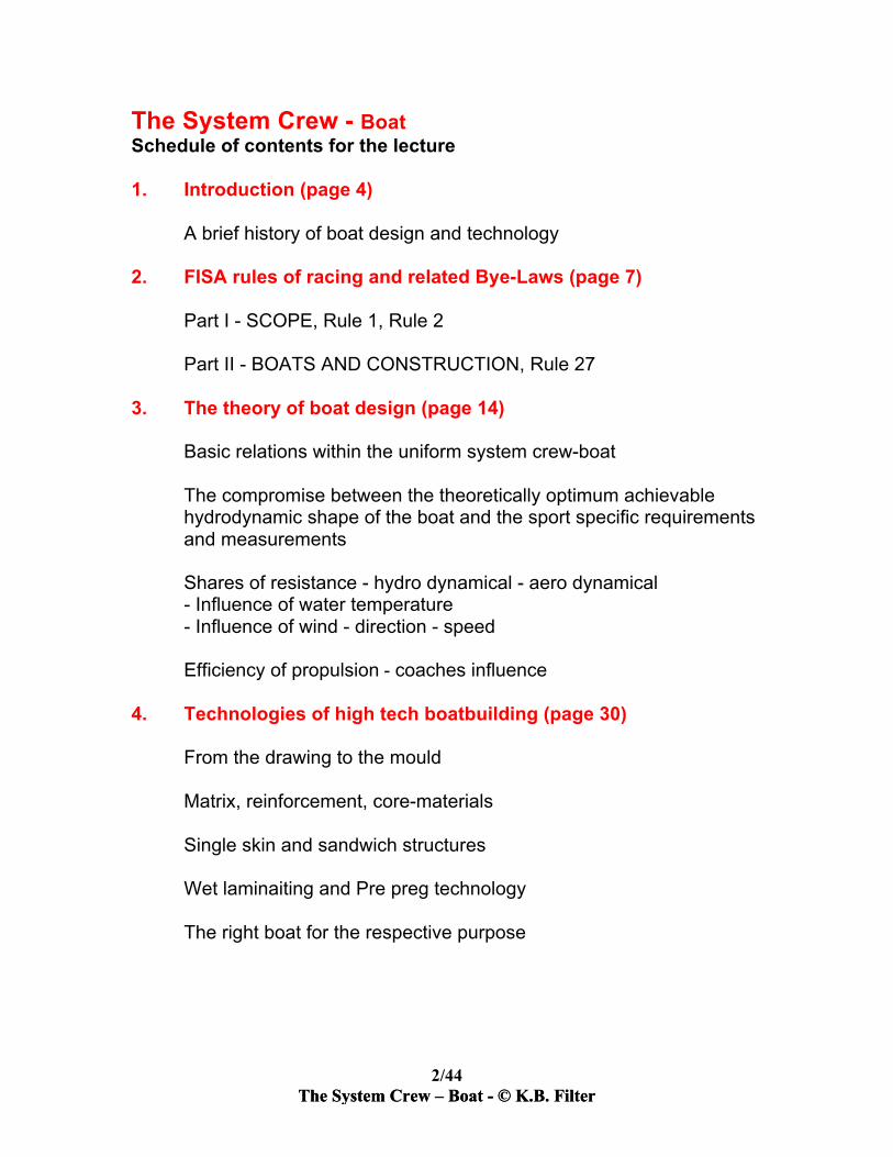
The System Crew - Boat Schedule of contents for the lecture 1. Introduction (page 4)
A brief history of boat design and technology
2. FISA rules of racing and related Bye-Laws (page 7)
Part I - SCOPE, Rule 1, Rule 2 Part II - BOATS AND CONSTRUCTION, Rule 27
3. The theory of boat design (page 14)
Basic relations within the uniform system crew-boat The compromise between the theoretically optimum achievable hydrodynamic shape of the boat and the sport specific requirements and measurements Shares of resistance - hydro dynamical - aero dynamical - Influence of water temperature - Influence of wind - direction - speed Efficiency of propulsion - coaches influence
4. Technologies of high tech boatbuilding (page 30)
From the drawing to the mould Matrix, reinforcement, core-materials Single skin and sandwich structures Wet laminaiting and Pre preg technology The right boat for the respective purpose

3/44 The System Crew – Boat - © K.B. Filter The System Crew – Boat - © K.B. Filter
5. Maintenance and repair (page 36) Stiffness of boat and boat speed State of wetted surface and boat speed
Most repairs are not too difficult, for example: How to repair a broken sandwich shell under a covered bow or stern section?
6. Rigging (page 45)
Basic measures Basic rules The importance of adaptation

4/44 The System Crew – Boat - © K.B. Filter The System Crew – Boat - © K.B. Filter
1. Design and materials in rowing 1. Introduction Rowing has a very long history with many different forms taking place worldwide. However, the origins of competitive rowing boats go back to the work boats of the professional watermen, especially from the rivers Tyne and Thames in England. Derived from the nature of their daily labour – bringing a load or a passenger to the required destination faster than other watermen – by the early nineteenth century professional watermen were already holding regattas using their own boats. When working rowing boats lost their role as a result of the introduction of steam boats, competitive and pleasure rowing spread, especially in universities and among the wealthy. In this period, the sport of ‘amateur rowing’ meant the exclusion of the waterman and other manual workers. Four developments enabled the evolution of traditional work boats into modern racing shells: • the outrigger; • the sliding seat; • the swivel oarlock; • the inside keel. The racing shell, with an inside keel, gunwhales from spruce, shell and saxboard from cedar wood and shoulders from ash, oak or maple wood remained for nearly 100 years with little change until new technologies in the materals field enabled the invention of new composites. The Olympic Games in Munich in 1972 saw for the first time competition between different composite shells made by different boat builders, and over time a sort of ‘arms race’ in boat building began. 2. FISA Rules of Racing and related Bye-Laws In 1979, the International Federation of Rowing Associations (FISA) formed a technical board to monitor and control the development of rowing materials. The FISA rules concerning equipment for rowing are focussed on fairness of competition and the safety of the athletes taking part. The definition of rowing Rule 1 – Rowing, Boats, Regattas Rowing is the propulsion of a displacement boat, with or without coxswain, by the muscular force of one or more rowers, using oars as simple levers of the second order and sitting with their backs to the direction of movement of

5/44 The System Crew – Boat - © K.B. Filter The System Crew – Boat - © K.B. Filter
the boat. Rowing on a machine or in a tank which simulates the action of rowing in a boat is also considered as rowing. In a rowing boat, all load bearing parts including the axes of moving parts, must be firmly fixed to the body of the boat, but the rower’s seat may move along the axis of the boat. A rowing regatta is a sporting competition consisting of one or more events divided, if necessary, into a number of races, in one or more classes of boats for rowers divided, as a general rule, into different categories of sex, age or weight. BoatsandconstructionRule 31 – Free Construction The construction, design and dimensions of boats and oars shall, in principle, be unrestricted subject to the limits laid down in Rule 1, paragraphs 1 and 2, and Rule 58. Nevertheless the Council of FISA may, in the Racing Bye-Laws, impose appropriate requirements. Bye-Law to Rule 31 – Boats and Equipment 1. Requirements for racing boats: 1.1 The bows of all boats shall be fitted with a white ball shape, minimum diameter 4 cm, in hard rubber or a hard material. If this is an external part it shall be firmly affixed to the bow of the boat, if an integral part of the hull construction it shall afford equivalent protection and visibility to a ball. 1.2 All boats and oars shall comply with the requirements set out in the Bye-Laws to Rule 41, below (name, symbol, etc.). 1.3 During racing, no wireless transmission equipment shall be used, whether for sending or receiving. 1.4 No substances or structures (including riblets) capable of modifying the natural properties of water or of the boundary layer of the hull/ water interface shall be used. 1.5 To avoid accidents arising from capsizing, all boats shall be equipped with stretchers or shoes that allow the competitors to get clear of the boat without using their hands and with the least possible delay. 1.6 The edges of blades must have a minimum thickness throughout as follows: – oars 5 mm, – sculls 3 mm. This thickness shall be measured 3 mm from the outer edge of the blade for oars and 2 mm for sculls. 1.7 The opening of the coxswain’s seat must be at least 70 cm long and

6/44 The System Crew – Boat - © K.B. Filter The System Crew – Boat - © K.B. Filter
it must be as wide as the boat for at least 50 cm. The inner surface of the enclosed part must be smooth and no structure of any sort may restrict the inner width of the coxswain’s section. 1.8 All boats used in eights events at World Rowing Championships, Olympic regattas, Olympic qualification regattas, Regional Games and Continental Championships and at all International regattas shall be in a minimum of two sections, with no section longer than 11.9 metres. 1.9 At World Championships, Olympic Regattas or Rowing World Cup regattas, the Council may require crews to carry on their boats such equipment as it considers desirable for the better promotion of the sport of rowing (e.g. mini cameras) provided that such equipment is identical for all boats in a race. 1.10 Boats constructed or delivered after 1 January 1998 must have a production plaque or equivalent visible and permanently affixed inside the boat, up to 50 sq cm in area, on which is written the name and address of the boat builder, its mark or logo, the year the boat was constructed, the average weight of the crew for which the boat is designed, and the weight of the boat on construction or upon delivery. 1.12 Length of Boats – Minimum length of racing boats – The minimum overall length of a racing boat shall be 7.20 metres. This will be measured from the front of the bow ball to the furthest aft extent of the boat, which may include an extension beyond the hull. If an extension is used it will be firmly affixed to the stern and terminate in a 4 cm ball as described in Bye-Law to Rule 31: 1.1. If a boat cannot be correctly aligned because it is less than the minimum overall length, the Starter may exclude the crew from the race. Rule 32 – Boat Weights All boats used at Olympic regattas or qualification regattas, World Championships, Rowing World Cup regattas, Regional Games and Continental Championships and all international regattas shall be of defined minimum weights. Bye-Law to Rule 32 – Boat Weights 1. Minimum boat weights are the following: 1x –14 kgs, 2x –27 kgs, 2− –27 kgs, 2+ –32 kgs, 4x –52 kgs, 4− –50 kgs, 4+ –51 kgs, 8+ –96 kgs 2. The minimum weight of the boat shall include only the fittings essential to its use; in particular – riggers, stretchers, shoes slides, seats and hull extensions. The minimum weight shall not include the oars or sculls, the bow number, any sound amplification equipment and loudspeakers or any other kind of electronic equipment.

7/44 The System Crew – Boat - © K.B. Filter The System Crew – Boat - © K.B. Filter
FISA guideline for safe rowing equipment Since 1 January 2007 the boatbuilder’s plaque, as described above in Bye-Law to Rule 31, must include additional information as described below. 1.11 Boats constructed or delivered after 1 January 2007 must also show on the production plaque (in 1.10 above) whether the boat meets “FISA’s Minimum Guidelines for the Safe Practice of Rowing”: “A boat when full of water with a crew of average weight equal to the design weight stated on the boat’s production plaque, seated in the rowing position should float such that the top of the seat is a maximum of 5 cm below the static waterline.” FISA guidelines indicate that the proper wording to be included on the plaque, in the same font and size as the other required information, is either: ‘This boat meets or exceeds the minimum flotation guideline’ or ‘This boat does not meet the minimum flotation guideline’ FISA has devised a special flotation test to be carried out by boat manufacturers for each model/size of boat to establish that any boat meets the guideline on the plaque. Rule 58 – Fairness – Innovation 1. Significant innovations in equipment including, but not limited to, boats, oars, related equipment and clothing, must meet the following requirements before they are allowed for use in FISA International Regattas; including World Championships and Olympic Games: a. They must be available to all competitors (no exclusive patents); b. The costs involved must be reasonable; c. There must be equal chances for all competitors; d. They must be safe and environmentally sound. 2. The innovation must be submitted to the FISA Executive Committee for evaluation. If it is judged to meet the above conditions and is approved for use, it must be readily available for all competitors by 1 January in order to be authorised for use in International regattas that year. Crews with unapproved innovations shall not be allowed to compete. The Executive Committee has the sole authority to decide all matters under this Rule including whether an innovation is significant, whether it is readily available, whether the costs are reasonable and whether it is safe and environmentally sound.

8/44 The System Crew – Boat - © K.B. Filter The System Crew – Boat - © K.B. Filter
3. The theory of boat design The compromise between the theoretically optimum achievable hydrodynamic shape of the boat and the sport specific requirements and measurements The following explanations, will give those theoretically inclined in-depth detailed descriptions of the forces that are the determinants in the design of racing shells, including a discussion about the properties of resistance and proper floatation. The resistance of a boat in water consists of two components; the frictional resistance and wave making resistance. When designing the hull of a boat the designer begins with the fact that it is obviously desirable that the shell has, as low a water resistance as possible but it still must be able to be rowed. It can be shown that these requirements leave us with a boat that, on average across the range of our boat types, has a frictional resistance that is approximately 85% of the total water resistance. Frictional resistance is directly proportional to the wetted surface of a hull. The result is that since this is such a large component of the total resistance, one tries to shape the boat so that the required displacement can be achieved with a minimum of wetted surface. The other 15% of drag are derived from wave making which is a very visible effect. This drag is created when a body (boat) is moved across a free surface such as the interface of the water and the air. The boat disturbs the general equilibrium by creating areas of high and low pressure and waves are made. In effect the boat creates waves along its way and consequently smaller waves mean less drag. For this discussion we will concentrate primarily on the friction drag since it is the largest component, easy to understand, and easiest to modify. Low frictional resistance is achieved by lowest wetted area, that will theoretically be achieved by a boat with semicircular cross-sections and with a reduction of the length of the boat down to the minimum where the wave drag begins to increase dramatically. These desirable aspects are contrary to the fact that the boat must have sufficient stability transversely as well as longitudinally.

9/44 The System Crew – Boat - © K.B. Filter The System Crew – Boat - © K.B. Filter
Concerning the transverse stability — this is in ship building the ability of a ship to right itself from a tilt — our rowing boats are unique in that they have no positive static stability, in other words the boats would be happier upside down. This is because the boats have an exceptionally high centre of gravity point with a crew sitting in them. Different are the 1x and 2x for adaptive rowing witch are wide enough to have a positive static stability.

10/44 The System Crew – Boat - © K.B. Filter
Height of bodies centre of gravity over waterline - (G) over (WL) Sketch for determination of the centre of gravity of the body during the recovery (phase between the strokes)
Part of the body Rel. Mass (%)
Distance over WL (cm)
Product (cm)
1 Head 0.07 93 6.51 2 Trunk 0.43 42.5 18.275 3 Upper arm 0.06 55 3.3 4 Forearms 0.04 36.5 1.46 5 Thighs 0.24 20 4.8 6 Calves 0.1 15 1.5 7 Hands 0.02 24 0.48 8 Feet 0.04 3 0.12
G over WL 36.445

11/44 The System Crew – Boat - © K.B. Filter
Heightofthecenterofgravityofthesystemcrew-boat
GoverWLPart Mass(kg) DistanceoverWL(cm) Product
Crew 160.0 36.4 5824.0
Boat 22.4 2.0 44.8Riggers 6.0 13.0 78.0Seats 1.6 4.0 6.4Oars 8.0 22.0 176.0
∑I 198.0 ∑II 6129.2
The transverse level results from the mass inertial forces of the system; which includes the rowers, boats and oars. This is especially true with the oars because they are comparable to the balancing pole of a tight ropewalker. The potential to control a racing boat is determined first by the technical performance of the crew but it is also important that the negative transverse stability is minimized as much as possible. The concept of stability will now be explained. For better comprehension we need a short theoretical contemplation of the forces acting on the boat: In the picture G means the centre of gravity, F the centre of buoyancy and MB the so-called apparent Metacentre. The latter is a point, which is theoretically derived resulting from the cut of the midship line, with a vertical line through the centre of buoyancy when a boat tilts. It may be seen that MB is the intersection above G.

12/44 The System Crew – Boat - © K.B. Filter
The French hydrograph and mathematician Pierre Bouguer (1698-1758) introduced the term “Metacentre”. The Centre of Gravity and the Centre of Floatation is in fact the centre of two forces, one acting downward (gravity) and one acting upward (floatation). This pair of forces centered at G and F produce in the case of a tilt a correcting or Righting Moment, which is what we find in any case for all “normal” boats and ships (a). In the case of our racing boat with crew MB is below G (b) and therefore the pair of forces instead of a Righting Moment produces a Capsizing Moment. The problem though is that the nearer the cross sections come to a total semicircle (which has the lowest wetted area) the bigger becomes the negative value of MBG. My calculations have shown that a double with a MBG of -0.24 m could be rowed well, but with an MBG of -0.28 m the limit was reached for most of the rowers. For this reason the shape of the cross-sections is an important consideration if one designs a boat for beginners or for top crews.

13/44 The System Crew – Boat - © K.B. Filter
The correct length of the boat is not only determined by hydrodynamic considerations. The length is responsible for the longitudinal stability, which is required to balance the fore and aft pitching induced by the continual movement of the crew. For example the length of a single with a sliding rigger where the crew is stationary could be reduced by 10% with the result of a reduction of the water resistance of 2%. The value of MLG for racing boats as the determinant of longitudinal stability is approximately twice the length. (For “normal” ships it corresponds to the length.) For the boat designer the underwater shape of a boat is characterized by specific data and calculated from the plan. As an example the data sheet of the most successful 2-/2x I have ever designed. On exhibition as “Redgraves successful boat” in the Henley River Museum it is described as a standard 2-, which it really has become, due to uncountable copies worldwide.

14/44 The System Crew – Boat - © K.B. Filter
DataSheet2-/2xLCWL 9.74m LengthoftheCWL(designedWL)BCWL 0.345m WidthoftheCWLT 0.119m Depth(WL-deepestpointofkeelline)L/B 28.24 Relationlength/widthB/T 2.90 Relationwidth/depthV 0.198m³ DisplacementS 3.2623m² WettedsurfaceF 0.0312m² AreaofthemaximumsectionχFCWL 2.3651m² AreaoftheCWLΔ 0.495 BlockcoefficientΑ 0.704 CWLcoefficientΒ 0.782 Maximumsectioncoefficient
0.633 Fineness(slimnesscoefficient)Rhy 12kp(118N) Hydrodynamicresistanceatstationaryspeed
5m/sandwatertemperature15°C
Specification of the dimensional less coefficients
Block coefficient

15/44 The System Crew – Boat - © K.B. Filter
Designed waterline coefficient
Maximum section coefficient
Fineness or Prismatic (slimness) coefficient

16/44 The System Crew – Boat - © K.B. Filter
BasicRelationswithintheuniformsystemcrew-boat
Vb Boatspeed (ms-1)
Rhy Hydrodynamicresistance(drag) (N)
Rae Aerodynamicresistance (N)
P Performanceofcrew (W)
Η Efficiencyofpropulsion
What can coaches influence or take in consideration Hydrodynamic resistance (Rhy) Choice of boat type: a boat built in accordance to the average weight of the crew means a boat with the least wetted surface.

17/44 The System Crew – Boat - © K.B. Filter
Caused by the motion of rowing by vertical movement and instationary speed, there is a resistance in addition to the results of the tank tests under stationary speed conditions of 6-1O%. This additional resistance can be reduced by the rowing technique. Curves of Rhy for different boat types
The influence of water temperature: The physical property or water changes depending on the temperature. Obviously the extremes are damp and ice. It is invisible in the liquid state but the mobility of the water molecules decreases at

18/44 The System Crew – Boat - © K.B. Filter
lower temperatures and with that the frictional resistance as well. When 2000-m-times of crews during a training period in spring and summer are compared take in consideration that the water temperature plays it’s share in the increase of performance. Change of the average boat speed in relation to the water temperature (warmer water = higher speed)
Examplecalculation(seediagrambefore)
Difference =1.32% = 2000 m times: 6’40”→ 6’34.7”

19/44 The System Crew – Boat - © K.B. Filter
Aerodynamic resistance (Rae) The system crew — boat above the waterline causes a resistance of approximately 13% of Rhy at the respective boat speed. This share can increase up to 4 times under headwind conditions and decrease to zero when the tallwind has boat speeds. The influence of wind forces decreases from lx to 8+ by the increasing inertial energy of the system crew — boat and the coverage of crewmembers.
The average shares of Rae Boat and riggers 15%
Crew 35% Oars 50%
Wind channel tests have shown that special profiles for the shafts of the oars can reduce up to 2O% when the shafts can turn within the profiles. In practice very difficult to realize because even the stiffest oars bend up to 150 mm. Other tests with different aerodynamic facings or wind defenders in front of the crew have shown no reductions within the range of “Reynolds numbers” caused by headwinds where we are racing. Measures of this kind are not to recommend for the following reasons: Rowing material becomes more complicated and more expensive The disadvantage of higher displacement occurs because such parts do not belong to the racing equipment of the boats Measures to recommend: In crews where the height of the bodies of the sitting athletes is different the tallest should be in the bow to give the best coverage and the smallest at the stroke to reduce the loosening resistance. Very disadvantageous is long hair. It increases the projection area of the head and when fluttering in headwind it can increase Rae up to 14%. Crews should wear caps where they can cover their hair under stronger headwind conditions.

20/44 The System Crew – Boat - © K.B. Filter
The kind of clothing has no influence as long as it does not flutter. To compare test and racing times under different wind conditions take the following table into consideration:

21/44 The System Crew – Boat - © K.B. Filter
Diagram of forces of air resistance (Rae)
Performance (P) It is not the subject of this lecture how to increase the performance of the athletes. We take the high performance athlete into consideration.

22/44 The System Crew – Boat - © K.B. Filter
Annotation: These dates of rowers of the US National Team are a good example for an average performance of good athletes. (In other sports)
The relation to the boat speed
Example calculation
For the efficiency of propulsion for a 2- with an average boat speed of 6 min 40 sec over 2000 m
Vb = 5 m/s
Rhy = 120.0 N (stationary speed)
Rtotal = 142.8 N
+6% = 7.2 N (add. From unstationary speed) +13% = 15.6 N (share of Rtae) ∑ = 142.8 N (total boat resistance) Performance of two average athletes with 460 W P = 920W

23/44 The System Crew – Boat - © K.B. Filter
It is the task of the coach to increase the value of η! Efficiency of propulsion (η) The efficiency of propulsion is the result of the rowing technique. It is the fact that athletes with the same biomechanical measurements, physical and physiological performance - the same “output” - row boats, built out of the same mould with the same rigging, but with a different average boat speed. This is the field where coaches have to concentrate on the search for the “secrets” of boat speed. A good coach can see a lot from outside but not everything. Many measuring systems have been developed in the past. Forces have been measured at the swivel, the stretcher, the handle and the blades of the oar. The results have often been surprising because athletes measured with lower forces could row faster. The result of a measuring system where stretcher and rigger are built as a closed system connected to the boat frictionless with roller bearings and fixed only by a measuring device make clear that many athletes waste a share of their positive input during and between the strokes. The advantage of this system is that the difference force between the contrary directed forces of swivel and stretcher is measured and in addition all forces resulting from the movement of the athlete over the whole cycle. Schematic course of propulsion (boat force) over the rowing cycle

24/44 The System Crew – Boat - © K.B. Filter
The results are individual handwritings of the rowing technique of each athlete. The curves show very clear the share of positive and negative forces affecting the boat over the whole cycle. The most mistakes are made between the strokes especially during the preparation of the stroke. Summarized some basic principles: Always look at crew and boat as a uniform system All changes need time for adaptation to come to proposed results. Take the developed dynamic stereotype into consideration. In general we achieve the best rowing technique when the whole motion, all velocities and accelerations are optimal harmonic, without peaks and inconstancies. In the result we have the minimal speed change of the boat over the rowing cycle and with that the highest average speed possible with the given output of a crew. 4. Technologies of hi-tech boatbuilding From the drawing to the mould In contrast to the construction of wooden shells where we have used positive cross sections (for massive wood) or plugs (for veneers) we need for any kind of plastic technology negative moulds. The quality of the mould is decisive for the quality of the boat made out of it. There are three main methods for our boat builders to get a mould: 1 Take a successful boat, which is still in good shape, and take a mould from it. This is the cheapest and fastest way and used by many boat builders worldwide. There is the disadvantage of often-uneven surfaces, which need a finishing treatment of surfacing and spraying for each boat. 2 Shape a plug corresponding to the drawing built up with massive wood, wooden ledges on cross sections or with hard foam. All these structures are covered after shaping with a

25/44 The System Crew – Boat - © K.B. Filter
Fiber-Reinforced-Plastic (FRP) composite and a sprayed plastic surfacer, which can finally be wet, sanded and polished. This technology is used by most boat builders who start with new designs. It needs normal workshop equipment but skilful workers who are able to work with an accuracy of about half a millimeter over length of one a meter. From such a polished plug you can take moulds where you get out shells protected with gelcoat ready for use. 3 A very exact method is to shape a plug computer controlled out of a block of foam with higher density. This method is mainly used In Marine Institutes with computer aided designs and also in the Aircraft Industry where they can afford the very expensive computer controlled milling machines with a length up to 20 m. The final surface treatment is the same as for method 2. Needs drawings created with a 3 D design program witch make it also easy to adopt designs to different requirements including CNC cutting of prepregs for precise laminating.
It is the task of any kind of technological research to find the optimum solution for the respective purpose. The materials and technologies we use today have never been developed for our boatbuilding. In this respect we are an appendage of the Aircraft Industry. This industry has of course the strongest demand for new materials with higher “strength-to-weight ratios” and the amounts of materials needed justify the expenditure of research in this field. More than 40 years ago the sandwich composite technology did find worldwide application. Simply stated a composite is a combination of different materials into a single structure to take advantage of the best properties of each material. Steel

26/44 The System Crew – Boat - © K.B. Filter
reinforced concrete and fiber reinforced plastics are composites but they are not the hi-tech sandwich composites we use for our boats with the highest strength to weight ratio. Sandwich composite structures use a low density, shear resistant core sandwiched between high-strength, high modulus skins of FRP materials. The skins are bounded to the core to prevent displacement between the layers when the composite is subjected to different loads. Together they create a synergistic structure with physical properties greater than the sum of the parts.
Matrix – reinforcement - core materials As matrix materials we use mainly liquid resins which convert through a chemical reaction to a thermoset solid. That sound complicated but it is just the so called curing procedure. The matrix resins have the task to support the reinforcing fibers and to distribute the forces affecting the structure to the fibers. In this respect it is very important that especially the ultimate elongation of the matrix is higher than the ultimate elongation of the fibers to avoid breakage and tears of the structure.
Resins used in boatbuilding — general overview Physical properties Price
index Purpose
Heat deflection temp. (°C)
Ultimate elongation (%)
Unsaturated Polyester 70 3 1 Training boats
and leisure sports Vinyl Ester
Resins 100 5 2

27/44 The System Crew – Boat - © K.B. Filter
Epoxy Resins 120 7
6 Boats for racing Epoxy Resins post cured 8 h 60°C
140 12
Fibers used for reinforcement have also different physical properties and also a respective price level. As for the different resins the density is nearly the same there are important differences between the fibers.
Fibers used in boatbuilding Physical properties Price
index Purpose
Density (g/cm³)
Ultimate elongation (%)
E modulus (GPa)
Fiber Glass 2.6 3 73 1
Mainly boats for training and leisure sports, in combination for racing
Aramid HM (Kevlar 49) (TwaronHM)
1.45 1.9 120 5 Mainly boats for racing, in combination with fiber glass also for training and leisure sports
Carbon Fiber HT 1.78 1.4 235 6
The right combination of fibers and resins is always a compromise between the optimum stiffness - weight ratio, the impact strength and of course the price relation. Core materials for sandwich composites used in boatbuilding are mainly honeycombs made from Aramid paper (Nomex) and hard PVC foams (Divinicell, Termanto). The same stiffness of a sandwich composite we get with honeycomb with a density of 60 kg/m³ and foam with a density of 90 kg/m³ but the impact strength of the foam sandwich is higher.

28/44 The System Crew – Boat - © K.B. Filter
Wet laminating and Pre preg technology WetlaminatingtechnologyMost boats are built using wet laminating technology with curing at room temperature. Combining with post this curing at medium temperature (50– 60 °C) results in laminates with good strength properties. Matrix materials are mainly epoxy resins with different hardeners for curing modifications. Wet laminated composites have limited strength properties when heated up. The temperature limit, Tg is highest after post-curing up to 100 °C. In certain circumstances, such as transport or storage with long exposure to sunlight and heat, the pressure of fixing belts can cause plastic deformation of the shell. For reinforcement, combined glass–aramid–carbon fabrics with different textures and weights per square meter are used. Woven carbon tapes with a high density of fibres are used for additional reinforcement in all directions where needed. It is likely that wet laminating technology will continue to be used in rowing boat building for racing at the lower level and for training and recreational boats because of the reasonable price of the product. Pre-pregtechnologyThe most advanced technology in many respects is pre-preg. Here one works with fibres that are machine pre-impregnated with modified resins. The material is flexible and sticky so it is easy to build up laminates without using wet resins. Its benefits are that the work is cleaner and the process ensures that the fibres contain the right amount of resin. The greatest advantage of the pre-preg technology is the potential to use layers of unidirectional (UD) carbon fibres. Optimal strength properties of the composite in all directions of load are achieved with a lay-up of a calculated amount of UD fibres in the direction required. Sample directions are (0°) for longitudinal stiffness, diagonally crossed (45°) for torsion stiffness and at night angles (90°) for transverse stiffness. The Tg of pre-preg composites depends on the type of resin system and a curing temperature of at least 120 °C. Figure 11.6 shows the construction of a boat using pre-preg technology. Advanced pre-preg technology enables the production of racing boats, complying with the FISA minimum weight limit, in accordance with the FISA Guidelines for Safety in Rowing with regard to the flotation requirements, i.e. the boat can be still rowed when full of water and is self-bailing through the rowing motion (see Fig. 11.7). The future of hi-tech racing boat building lies in advanced pre-preg technology. Moreover, a hurdle for the introduction of this technology is the high investment needed, particularly for specialist workshops with appropriate air conditioning, heat-resistant moulds and industrial ovens or autoclaves for the curing procedure.

29/44 The System Crew – Boat - © K.B. Filter
Fig.11.6Boat construction using pre-preg technology (Nomex® DuPont)
Not all carbon fibres used in boat building and other applications are the same. The main difference is the grade of carbonisation of the organic fibres under high temperature which determins the strenght properties of the fibres but also the price because of the energy needed for the carbonisation. Low modulus fibres often used for woven materials are cheap but have lower strength properties.
Another aspect is the direction of the fibres in woven materials there is mostly the same amount of fibres in warp and weft direction, except unidirectional tapes for special reinforcements with more fibres in warp direction. In woven materials the fibres respective the threads cross each other so they are not totally stretched and that reduces also the strenght properties and needs more resin to fill the gaps . But woven carbon fibre is easy to work up even for wet layup technology so it is the most used material.
Deck construction -Clear coat -UD pre-preg carbon fibre (multiple layers) -Nomex honeycomb core -UD prepreg carbon fibre (multiple layers) -Epoxy used to bond deck to hull Hull construction -UD pre-preg carbon fibre (multiple layers) -Nomex honeycomb core -UD-pre-preg carbon fibre (multiple layers) -Primer -Paint

30/44 The System Crew – Boat - © K.B. Filter
The following pictures show the difference between woven and UD-carbon fibres.

31/44 The System Crew – Boat - © K.B. Filter
Fig.11.7Photo showing bailing outlets on self-bailing boat The right boat for the respective purpose To get the right boat for the respective purpose is mainly an economical question. For the same boat type the weight given by the technology and material used, determines the price. Boats for international top level (A Grade) built according to the FISA weight limits and an approved stiffness test. These boats have sandwich structure. The outside laminate made from Aramid (Kevlar 49) fibers is strong against impact. The Nomex honeycomb as core material is approved worldwide. The inside laminate made from carbon fiber gives longitudinal and torsional stiffness. Keel and gunwales are reinforced with unidirectional carbon tapes. The monocoque decks of carbon fiber and the carbon shoulders give additional stiffness. Though the outside laminate of the A Grade boats is made from Kevlar the sandwich structure is not totally safe against damages, which can happen in the daily club training. It is also obvious that not all crews need the relative expensive sandwich boats at FISA weight level. For that reason we have developed the B Grade club boat good for all training purposes and also for competitions.

32/44 The System Crew – Boat - © K.B. Filter
The specific of this construction is an elastic single skin shell in the most endangered region of the boat. The shell contains a glassfibre laminate reinforced with unidirectional carbon tapes and a partly sandwich structure with Nomex honeycomb in the gunwale and saxboard region. The inside structure is like the A Grade and the weight is about 12 % over the FISA limit. All stiffness values are the same as the A Grade have. Advantages for the clubs are durability and the price level. The following shows a sample calculation for the influence of boat weight on the racing speed of a given crew: An 8 + (boat A) built from the same mould with the same stiffness, but with higher weight caused by cheaper materials and technology, can be produced up to 30 % cheaper than a hi-tech boat (boat B) built at or under the FISA weight limit. Displacement A (Δ2): boat 110 kg crew and oars 761 kg = 871 kg Displacement B (Δ1): boat 96 kg crew and oars 761 kg = 857 kg Using a formula derived from the tank tests of the ‘Versuchsanstalt fur Wasserbau und Schiffbau Berlin’ Report no. 52/10 and an average racing speed vA = 5.8 m/s for the heavier boat (i.e. a time of 2000 m if 5 min 44.4 sec), the speed of the lighter boat vB can be calculated from the following. The speed difference vdiff between boat A and boat B is given by:
The time difference over the racing distance is 0.9 sec which makes an advantage of 5.2 m for the lighter boat over the 2000 m racing distance. It is obvious that in international competitions at the highest level lighter boats will be used. For intermediate crews with lower technical ability the light boat can be a disadvantage because it does not tolerate mistakes and the average speed can decrease in these circumstances.

33/44 The System Crew – Boat - © K.B. Filter
5. Maintenance and repair Stiffness of boat and boat speed There are two main relatives where a lack of stiffness causes a negative influence on the speed of the boat. Lack of longitudinal stiffness: The boat bends too much under the load of the crew and does not float at the hydrodynamical optimum waterline. Under the changing vertical forces caused by the movement of the crew and the oars higher vibrations of the shell enlarge the turbulence of the boundary layer and with that the share of the frictional resistance. Lack of stiffness of the load bearing parts like oars, riggers, shoulders, stretchers including the torsion stiffness of the boat: Any kind of deformation of load bearing parts changes the exact rigging measures like for example the height of the swivel over the waterline in case of weak shoulders, riggers and torsion of the boat or the pitch when the pin bends. Even worse when we come into the range of plastic (strain) deformations. In addition any elastic deformation of material needs energy, which is stored but in our case lost because we cannot use it like a pole-vaulter. For example we do not have time at the end of the stroke to wait until the bent oar has totally stretched. We hear it very clearly when the released shaft bangs against the sternward side of the swivel at the end of the stroke. I always recommend stiff boats and oars especially for top crews to avoid any loss of energy for propulsion.

34/44 The System Crew – Boat - © K.B. Filter
Standard arrangements for stiffness test of boats (a) Longitudinal stiffness
Type of boat L (mm) f1 (mm) (max)
1x 2500 10 2x 3500 8 2- 3500 8 2+ 3700 8 4x 4500 7 4- 4500 7 4+ 4500 7 8+ 6300 10
(b) Stiffness of riggers and shoulders

35/44 The System Crew – Boat - © K.B. Filter
(a) and (b) must be measured at the upper edge of the sax board (a) for sculling across between the shoulders and (b) rowing diagonal between the shoulders Difference d of (a) and (b) under load and without load To check the torsional stiffness of fours and eight’s measure “f” and “b” with stroke and bow riggers under load.

36/44 The System Crew – Boat - © K.B. Filter
The stiffness test for oars that I developed in the sixtieth as a National Standard test for quality has become since that times a well known worldwide application. This standard includes also the position of the centre of gravity, which is important for the calculation of the moment an oar has at the swivel. Sculls and sweep oars should always be combined to pairs with the same moment (M) for better balance of the boat.
d = distance collar – center of gravity (M) m = mass of the oar (kg)
State of wetted surface and boat speed Because of the high share of frictional resistance the roughness of the surface, in hydrodynamics defined as grain size, plays an important role. It is physically smooth when wet sanded with grain 600 paper. It is unimportant if the surface looks shiny or not. But a dirty surface very often caused by polluted water increases the roughness of the surface above unacceptable limit. Cleaning with liquid detergent as used for dishwashing at least before each race is compulsory. Adherence of dirt and cleaning can be reduced when the surface is protected with concentrated polymer, which covers with a glass like film for a long time. The often seen polishing with car waxes is not advantageous because the wax increases the molecular tension within the boundary layer (in the FISA rules named the surface layer) and with that the frictional resistance. There are methods, which cause the opposite like macromolecular substances or the so named riblets but they are forbidden by our rules. Repair of broken hulls with cored skins (Sandwich structure) In boat repair seminars it was always very useful to demonstrate the repair of a sandwich hull located in the canvas area where the deck allows only the work from outside (described in the following steps 1-13). From this kind of repair you can derive most other hull repair because they are easier. 1 Cut off all parts which are broken or deformed, especially from the outer skin and parts of the core which are delaminated either from the outer or inner skin. If the inner skin is not broken it shall remain.

37/44 The System Crew – Boat - © K.B. Filter
2 All around the hole in the outer skin remove the core at least 8 mm deep under the edge of the outer skin. (See picture below)

38/44 The System Crew – Boat - © K.B. Filter
3 When the inner skin is yet present strengthen it with a larger piece of glass twill weave ( ~ 200g/m²). Twill weave is better than linen weave because it is more flexible. 4 Cut the size of the glass woven according to the hole but all around 20 mm wider. Soak it with resin as described before, bring it into the hole and give it a good connection to the inner skin and all around to the remaining core and the outer skin. Stretch it into the gap between the inner and outer skin. Let the layer harden. 5 Cut of hardened overlaps of the laminate all around the hole. To fill up the hole prepare a kind resin foam or light putty made from resin filled with micro balloons (powder of micro glass bubbles) or if not available with other light materials like saw dust. Fill it up not thicker than up to the under side of the outer skin. All around let a gap under the outer skin to bring the covering layer of glass woven into contact to the underside of the outer skin. It is useless to try to feather the very thin laminates of a sandwich hull. An overlap under the outer laminate is the best. Bring the covering laminate (glass woven 200g/m2) in when the light putty” is not yet fully hardened, when it is yet flexible. Control with a ruler that there is nothing higher than the level of the hull.

39/44 The System Crew – Boat - © K.B. Filter
6 After hardening of the covering layer fill up remaining hollows with fast hardening surface. Use a wide spatula. Then go on to hull refinishing.
7 To close a hole where the inner laminate is also destroyed you have to prepare a plain laminate from at least two layers of glass weave (100-200g/m2). Prepare the laminate one day before on a plain area covered with stretched release foil as described before and let it harden. 8 The larger the hole or the less bend the area of the hole is (near the keel or gunwale) the stiffer the laminate must be. The laminate must be so large that it overlaps all around the hole at least by 30 mm. (see next picture)
9 Now sand the under side of the inner skin with 80 grit sandpaper a little wider than the size of the prepared laminate is.

40/44 The System Crew – Boat - © K.B. Filter
10 Put the prepared laminate on the hull and mark the size of the hole with a dark marker very clearly. Prepare two pieces or not too soft wires with rectangular hooks at one end; drill at least two holes with the diameter of the wire into the prepared laminate. The holes shall lie on a line, which marks the highest point of the banded hull. Pierce the hooks of the wires through
the holes and use the wires as handles to bring the laminate into the hole. When it is in the right (the marked) position pull at the wires to control if the now banded laminate lies close to the under skin all around the hole. (see pictures below)

41/44 The System Crew – Boat - © K.B. Filter
11 Take the laminate out and soak a piece of strand mat (300g/m2) with the same size on it. 12 Insert the laminate with the soaked strand mat into the hole in the right position and bring with a helping construction under tension. 13 Move the wedges under the ledge with feeling. Stop when some resin is squeezed out of the soaked strand mat all around the edge of the inner skin. After hardening continue as described for a hole where the inner skin was not destroyed.

42/44 The System Crew – Boat - © K.B. Filter
6. Rigging Basic measures The basic measures for rigging are the seat height over the waterline and the position of the swivel lengthways. These positions are given through the calculations for the displacement according to the average weight of the crew that the boat is built for, and the accordance of the centre of gravity and the centre of buoyancy. All other measures are changeable to adapt to individual body size and the requirements of the respective rowing technique. It is not the purpose of this lecture to tell experienced coaches how to rig a boat. It is just to remember the basic rules and relations that are sometimes not in mind during the everyday routine work. If the “working place” of an athlete is rigged within the range of measures given in the following tabloid it should be suitable for women and men including juniors. For children I have given special recommendations published in the FISA Youth and Junior Rowing and Sculling Guide.
Sport specific measures

43/44 The System Crew – Boat - © K.B. Filter
a 14 - 17 cm b 15 - 18 cm c (From 1x to 8+) 7 - 10 cm d 22 - 26 cm e
1x 79 - 81 cm 2x 78 - 80 cm 2- 85 - 87 cm 2+ 86 - 88 cm 4x 78 - 80 cm 4- 84 - 86 cm 4+ 85 - 87 cm 8+ 83 - 85 cm
Basic relations 1 Control always the vertical position of the pin, check the pitch at catch, perpendicular and release position. Check at the blade, because not all oars have really the same pitch at the sleeve. Experienced rowers do not need lateral pitch of the pin. Even beginners should learn to keep the depth of the blades in the water without getting such an aid. 2 The higher the swivels are rigged over the waterline and seat the less the pitch can be. Big blades need because of their asymmetric shape generally less pitch than Macon blades. 3 It is to recommend using lower decking and rails and higher seats to enable the rowers to stretch their legs better during the stroke. To bring just the stretcher higher reduces the arc of the oar at the catch; even the stretcher has the right length position. Consider that most of the roller bearing seats are built lower than the double action seats and that makes this problem more crucial. 4 Mistakes are often made with the use of overlong rails of more than 80 cm length. I have measured distances of 14 - 16 cm between the face of the gate and the end of the rails sternwards. That causes a very acute knee angle with a position of the under leg inclined towards the stern. From this position it is impossible to use the legs in the right way for the first part of the stroke. On the other hand too acute knee angles are mostly the reason for knee problems.

44/44 The System Crew – Boat - © K.B. Filter
The importance of adaptation The final goal of any kind of individual adaptation especially in crew boats is to achieve the same stroke length with the same arcs at the catch and the release with an exactly corresponding timing. Many coaches want to achieve that with the same measures of spread, span and oars even some of the athletes have different biomechanical conditions as for example a sculler with shorter arms and trunk in a quad. This athlete will be always under tremendous stress to have the same arc at the catch like the others. Do not hesitate to give such an athlete less span and shorter inside levers. When he has qualified for a top crew under his lack of biomechanical conditions he must be very powerful and with the changed rig he is able to row in the same relaxed way like the other crew members. In the search for better solutions never change several measures at the same time, except measures that are interdependable. One will never know what is the reason for these different results. Never expect that a theoretically better solution will bring you an advantage from the first moment on when you try it. One needs the patience to adapt to the new conditions. Rowing is a sport with a cyclic motion where a dynamic stereotype will be developed in any case. Keep in mind that it is very often not the right one!