
THE STUDY ON THE IMPROVEMENT MEASURES …open_jicareport.jica.go.jp/pdf/11838968.pdfThe Study on the...
119
No. Ministry of Energy and Mineral Resources The Republic of Indonesia THE STUDY ON THE IMPROVEMENT MEASURES FOR ELECTRIC POWER GENERATION F ACILITIES IN JAVA-BALI REGION IN THE REPUBLIC OF INDONESIA FINAL REPORT < SUMMARY > November 2006 JAPAN INTERNATIONAL COOPERATION AGENCY NEWJEC INC. THE KANSAI ELECTRIC POWER CO., INC. E D J R 06-127
-
Upload
nguyenminh -
Category
Documents
-
view
214 -
download
0
Transcript of THE STUDY ON THE IMPROVEMENT MEASURES …open_jicareport.jica.go.jp/pdf/11838968.pdfThe Study on the...

No.
Ministry of Energy and Mineral Resources The Republic of Indonesia
TTHHEE SSTTUUDDYY OONN TTHHEE IIMMPPRROOVVEEMMEENNTT MMEEAASSUURREESS FFOORR
EELLEECCTTRRIICC PPOOWWEERR GGEENNEERRAATTIIOONN FFAACCIILLIITTIIEESS IINN JJAAVVAA--BBAALLII RREEGGIIOONN
IINN TTHHEE RREEPPUUBBLLIICC OOFF IINNDDOONNEESSIIAA
FFIINNAALL RREEPPOORRTT << SSUUMMMMAARRYY >>
NNoovveemmbbeerr 22000066
JAPAN INTERNATIONAL COOPERATION AGENCY
NEWJEC INC. THE KANSAI ELECTRIC POWER CO., INC.
E D
J R
06-127

PREFACE
In response to a request from the Government of Republic of Indonesia, the Government of Japan decided to conduct the Study on the Improvement Measures for Electric Power Generation Facilities in Java-Bali Region in the Republic of Indonesia, and the study was implemented by the Japan International Cooperation Agency (JICA). JICA selected and dispatched a study team headed by Mr. Yasuharu Matsuda of the NEWJEC Inc., and consist of NEWJEC Inc. and KANSAI Electric Power Co., Inc. to Indonesia five times from November 2005 to October 2006. The study team held discussions with the officials concerned of the Government of Indonesia and PT. PLN (Persero), and conducted related field surveys. After returning to Japan, the study team compiled the final results in this report. I hope this report will contribute to improvement of electric power generation facilities and to enhancement of friendly relations between our two countries. I wish to express my sincere appreciation to the officials concerned of the Government of Indonesia for their close cooperation throughout the study.
November 2006
Tadashi IZAWA Vice President Japan International Cooperation Agency
November, 2006
LETTER OF TRANSMITTAL
Mr. Tadashi Izawa Vice President Japan International Cooperation Agency Tokyo, Japan We are pleased to submit to you the report on the Study on the Improvement Measures for Electric Power Generation facilities in Java-Bali Region in the Republic of Indonesia. This study was conducted by NEWJEC Inc., in association with KANSAI Electric Power Company Co., Inc. under a contract to JICA, in a period from October 2005 to November 2006. During the course of the study, the study team visited objective sixteen power stations and developed improvement measures for electric power generation facilities including operation and maintenance to meet a short/medium-term power demand in the relevant region. Concerning power generation facilities, repowering plans in combination with shutdown of the existing less efficient power stations were proposed, in consideration of a current expensive fuel oil. For operation and maintenance aspects, effective measures to prevent the current frequent forced outages were proposed, based on the analysis of causes of forced outages and the current situation. Furthermore, technology transfer relating to Remaining Life Assessment aiming for effective and appropriate operation and maintenance was conducted. We dearly wish that our proposed measures will contribute to the improvement of reliability of power supply and to the alleviation of the current tight balance of power supply-demand in Java-Bali region. We would like to take this opportunity to express our sincere gratitude to your Agency, the Ministry of Foreign Affairs and the Ministry of Economy, Trade and Industry. We are also most grateful for the cooperation and assistance from the officials and personnel concerned in Indonesia, the Ministry of Energy and Mineral Resources, PT PLN (Persero), Indonesia Power, PJB and each power station.
Very truly yours, __________________________ Yasuharu Matsuda Team Leader, The Study on the Improvement Measures for Electric Power Generation Facilities in Java-Bali Region in the Republic of Indonesia
The Study on the Improvement Measures for Electric Power Generation Facilities in Java-Bali Region in the Republic of Indonesia
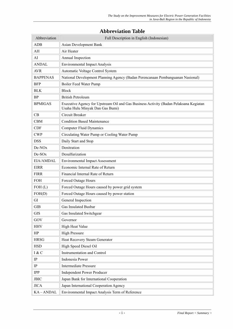
Abbreviation Table Abbreviation Full Description in English (Indonesian)
ADB Asian Development Bank
AH Air Heater
AI Annual Inspection
ANDAL Environmental Impact Analysis
AVR Automatic Voltage Control System
BAPPENAS National Development Planning Agency (Badan Perencanaan Pembanguanan Nasional)
BFP Boiler Feed Water Pump
BLK Block
BP British Petroleum
BPMIGAS Executive Agency for Upstream Oil and Gas Business Activity (Badan Pelaksana Kegiatan Usaha Hulu Minyak Dan Gas Bumi)
CB Circuit Breaker
CBM Condition Based Maintenance
CDF Computer Fluid Dynamics
CWP Circulating Water Pump or Cooling Water Pump
DSS Daily Start and Stop
De-NOx Denitration
De-SOx Desulfurization
EIA/AMDAL Environmental Impact Assessment
EIRR Economic Internal Rate of Return
FIRR Financial Internal Rate of Return
FOH Forced Outage Hours
FOH (L) Forced Outage Hours caused by power grid system
FOH(D) Forced Outage Hours caused by power station
GI General Inspection
GIB Gas Insulated Busbar
GIS Gas Insulated Switchgear
GOV Governor
HHV High Heat Value
HP High Pressure
HRSG Heat Recovery Steam Generator
HSD High Speed Diesel Oil
I & C Instrumentation and Control
IP Indonesia Power
IP Intermediate Pressure
IPP Independent Power Producer
JBIC Japan Bank for International Cooperation
JICA Japan International Cooperation Agency
KA – ANDAL Environmental Impact Analysis Term of Reference
- i - Final Report < Summary >
The Study on the Improvement Measures for Electric Power Generation Facilities in Java-Bali Region in the Republic of Indonesia
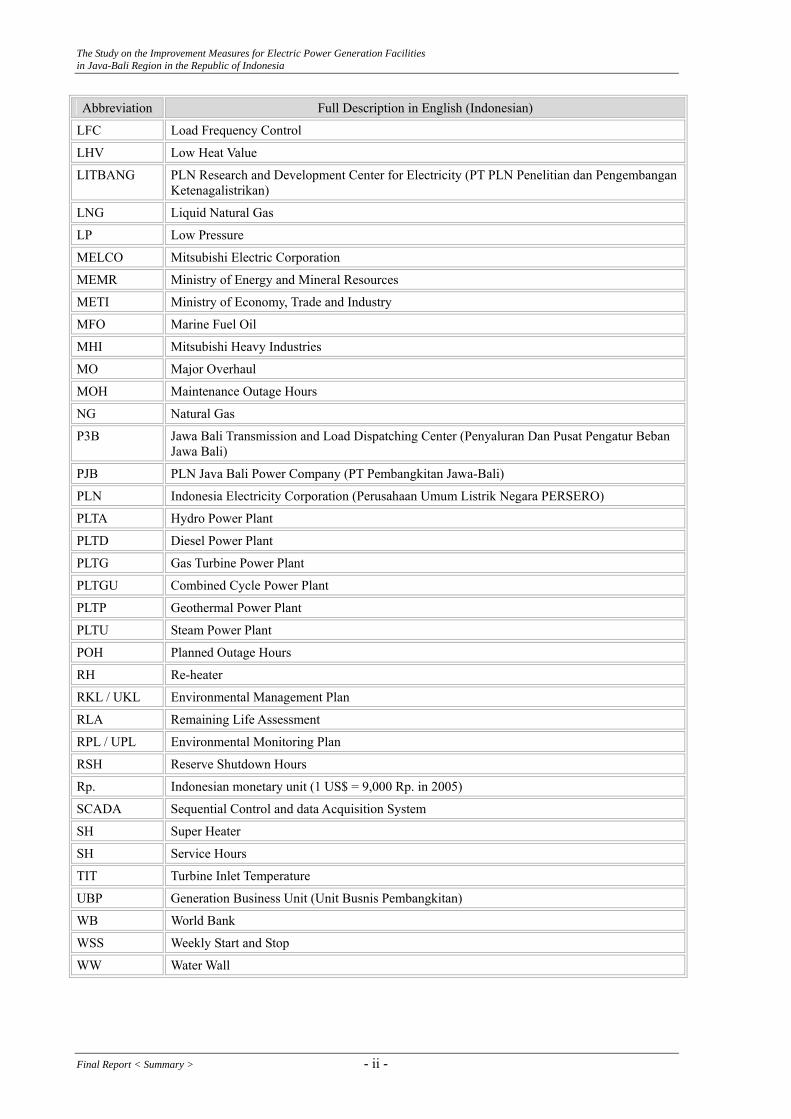
Abbreviation Full Description in English (Indonesian)
LFC Load Frequency Control
LHV Low Heat Value
LITBANG PLN Research and Development Center for Electricity (PT PLN Penelitian dan Pengembangan Ketenagalistrikan)
LNG Liquid Natural Gas
LP Low Pressure
MELCO Mitsubishi Electric Corporation
MEMR Ministry of Energy and Mineral Resources
METI Ministry of Economy, Trade and Industry
MFO Marine Fuel Oil
MHI Mitsubishi Heavy Industries
MO Major Overhaul
MOH Maintenance Outage Hours
NG Natural Gas
P3B Jawa Bali Transmission and Load Dispatching Center (Penyaluran Dan Pusat Pengatur Beban Jawa Bali)
PJB PLN Java Bali Power Company (PT Pembangkitan Jawa-Bali)
PLN Indonesia Electricity Corporation (Perusahaan Umum Listrik Negara PERSERO)
PLTA Hydro Power Plant
PLTD Diesel Power Plant
PLTG Gas Turbine Power Plant
PLTGU Combined Cycle Power Plant
PLTP Geothermal Power Plant
PLTU Steam Power Plant
POH Planned Outage Hours
RH Re-heater
RKL / UKL Environmental Management Plan
RLA Remaining Life Assessment
RPL / UPL Environmental Monitoring Plan
RSH Reserve Shutdown Hours
Rp. Indonesian monetary unit (1 US$ = 9,000 Rp. in 2005)
SCADA Sequential Control and data Acquisition System
SH Super Heater
SH Service Hours
TIT Turbine Inlet Temperature
UBP Generation Business Unit (Unit Busnis Pembangkitan)
WB World Bank
WSS Weekly Start and Stop
WW Water Wall
Final Report < Summary > - ii -

The Study on the Improvement Measures for Electric Power Generation Facilities in Java-Bali Region in the Republic of Indonesia
Unit Table Abbreviation Unit
bbl Barrel (1 bbl = 159 litter)
GWh Gigawatt-hour
kW Kilowatt
kWh Kilowatt-hour ( 1 kWh = 860 kcal) (1 kcal = 3.968 BTU)
MMBTU 106 British Thermal Unit (MM = 106)
MMSCF 106 Standard Cubic Feet (MM = 106)
mmscfd Million Standard Cubic Feet per Day
MSCF 103 Standard Cubic Feet (M = 103)
MVA Mega-volt-ampere
MW Megawatt
MWh Megawatt-hour
VA Volt-ampere
References
(1) “The Project Formation Study for the Improvement of Utilization of Electric Power Facilities in Java-Bali Region in the Republic of Indonesia”, September 2003, JICA
(2) “The Preliminary Study for the Study on the Improvement Measures for Electric Power Generation Facilities in Java-Bali Region”, June 29, 2005, JICA
(3) “Basic Strategy of Japan’s ODA Loan (The Medium-Term Strategy for Overseas Economic Cooperation)”, April 2005, Japan Bank for International Cooperation
(4) “Ex-post Evaluation Report on ODA Loan Project 1999 (Gas Firing Modification Works of Gresik Steam Power Plant Units III and IV)”, Japan Bank for International Cooperation
(5) “Ex-post Evaluation Report on ODA Loan Project 2002 (Priok Steam Power Plant Unit 3 & 4 Rehabilitation Project)”, Japan Bank for International Cooperation
(6) “Study Report for CDM/JI 2004 (Feasibility Study on the Effective Utilization of Biogas Recovery at Waste Disposal in Indonesia)”, 2004, KAJIMA Corporation and YACHIYO Engineering CO., LTD.
(7) “Policy Working Paper 2438 (Measurements of Poverty in Indonesia 1996, 1999, and Beyond)”, 2000, The World Bank
- iii - Final Report < Summary >
The Study on the Improvement Measures for Electric Power Generation Facilities in Java-Bali Region in the Republic of Indonesia
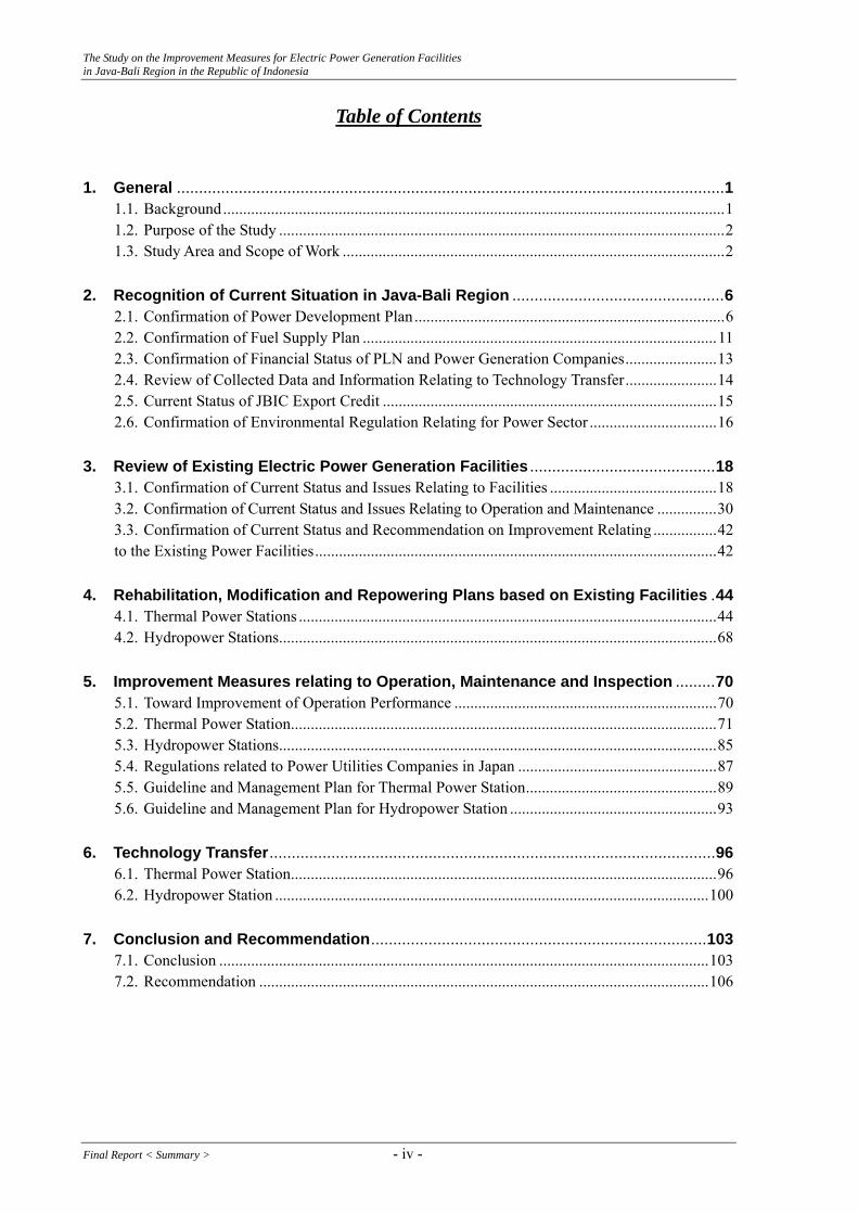
Table of Contents
1. General ............................................................................................................................1 1.1. Background..............................................................................................................................1 1.2. Purpose of the Study ................................................................................................................2 1.3. Study Area and Scope of Work ................................................................................................2
2. Recognition of Current Situation in Java-Bali Region ................................................6 2.1. Confirmation of Power Development Plan..............................................................................6 2.2. Confirmation of Fuel Supply Plan .........................................................................................11 2.3. Confirmation of Financial Status of PLN and Power Generation Companies.......................13 2.4. Review of Collected Data and Information Relating to Technology Transfer.......................14 2.5. Current Status of JBIC Export Credit ....................................................................................15 2.6. Confirmation of Environmental Regulation Relating for Power Sector ................................16
3. Review of Existing Electric Power Generation Facilities ..........................................18 3.1. Confirmation of Current Status and Issues Relating to Facilities ..........................................18 3.2. Confirmation of Current Status and Issues Relating to Operation and Maintenance ...............30 3.3. Confirmation of Current Status and Recommendation on Improvement Relating ................42 to the Existing Power Facilities.....................................................................................................42
4. Rehabilitation, Modification and Repowering Plans based on Existing Facilities .44 4.1. Thermal Power Stations .........................................................................................................44 4.2. Hydropower Stations..............................................................................................................68
5. Improvement Measures relating to Operation, Maintenance and Inspection .........70 5.1. Toward Improvement of Operation Performance ..................................................................70 5.2. Thermal Power Station...........................................................................................................71 5.3. Hydropower Stations..............................................................................................................85 5.4. Regulations related to Power Utilities Companies in Japan ..................................................87 5.5. Guideline and Management Plan for Thermal Power Station................................................89 5.6. Guideline and Management Plan for Hydropower Station ....................................................93
6. Technology Transfer.....................................................................................................96 6.1. Thermal Power Station...........................................................................................................96 6.2. Hydropower Station .............................................................................................................100
7. Conclusion and Recommendation............................................................................103 7.1. Conclusion ...........................................................................................................................103 7.2. Recommendation .................................................................................................................106
Final Report < Summary > - iv -
The Study on the Improvement Measures for Electric Power Generation Facilities in Java-Bali Region in the Republic of Indonesia
1. General 1.1. Background
Power demand in the Republic of Indonesia has steadily increased since the economic crisis in 1997. However, the power supply system to the consumers still does not seem to work efficiently and seems to become the bottleneck toward the economic recovery in Indonesia. For the above reason, JICA carried out the study on the optimum power sources development in Java-Bali system (Power Sector Study for the Optimum Power Sources Development) from 2001 to 2002. In the Study, JICA proposed recommendations on short-term countermeasures and mid-term plans from the viewpoint of stable power supply especially in Java-Bali system, because the occurrence of shortage of reserve margin for power supply in Java-Bali system in 2004 had been anticipated. And the immediate implementation of those recommendations was required. Based on the above needs, JICA conducted “Basic Study for Project Formation Related to Mining and Manufacturing (The Study on the Improvement Utilization for Electric Facilities in Java-Bali Region in the Republic Indonesia)” in June 2003. In the Preliminary Study, JICA mission studied on the current situation and identified the issues relating to the improvement measures for existing power generation facilities recommended in the Study in 2003, and formulated a specified project resulting from the confirmation of needs and consultation with relevant organizations in Indonesia. The specific content was stipulated in the Minutes of Meeting agreed on July 3, 2003 between JICA, Ministry of Energy and Mineral Resources (MEMR) and PT. PLN (Persero). Based on the Project Formation Study, the Government of Republic of Indonesia officially requested the Government of Japan to implement the Study on the Improvement Utilization for Electric Facilities in Java-Bali Region in July 23, 2004 and the Government of Japan accepted the request and decided to conduct the Study in 2005. The tight power supply balance in Java-Bali region envisaged at the project formation study was fortunately avoided due to the effect by tariff hike and depressing power demand such as restricted connection to new customers which had been imposed up to July 2003. In year 2004, the actual demand under ran the projected demand. In year 2005, power demand has been increasing again and exceeded the past maximum peak load. On the other hand, any power stations except an expansion of thermal station (Muara Tawar Gas Turbine: 858 MW) have not been reinforced up to now since the economic crisis. For the above reason, the phenomena of shortage for power supply and appreciate reserve margin were observed since April 2005. The envisaged tight power supply balance imposing
- 1 - Final Report < Summary >
The Study on the Improvement Measures for Electric Power Generation Facilities in Java-Bali Region in the Republic of Indonesia
forced-demand control for large consumers has become the realistic issue. In year 2006, new power stations are scheduled to start the commercial operation. On the other hand, due to the increase of power demand and decrease of exploitation of gas and oil in Indonesia, it is worried about stable supply of fuels for power stations. Further more, due to the difficulty of land acquisition, transmission expansion plan cannot keep the implementation schedule, which means that tight supply balance might not be resolved even though new power stations are put into operation. For the above reasons, the study on the improvement measures for electric power generation facilities is expected.
1.2. Purpose of the Study
The purpose of the Study is to develop the improvement measures for existing power stations to meet the power demand in short and middle terms in Java-Bali region based on the above background and to conduct the technology transfer relating the effective and appropriate operation and maintenance for the existing power stations.
1.3. Study Area and Scope of Work 1.3.1. Study Area
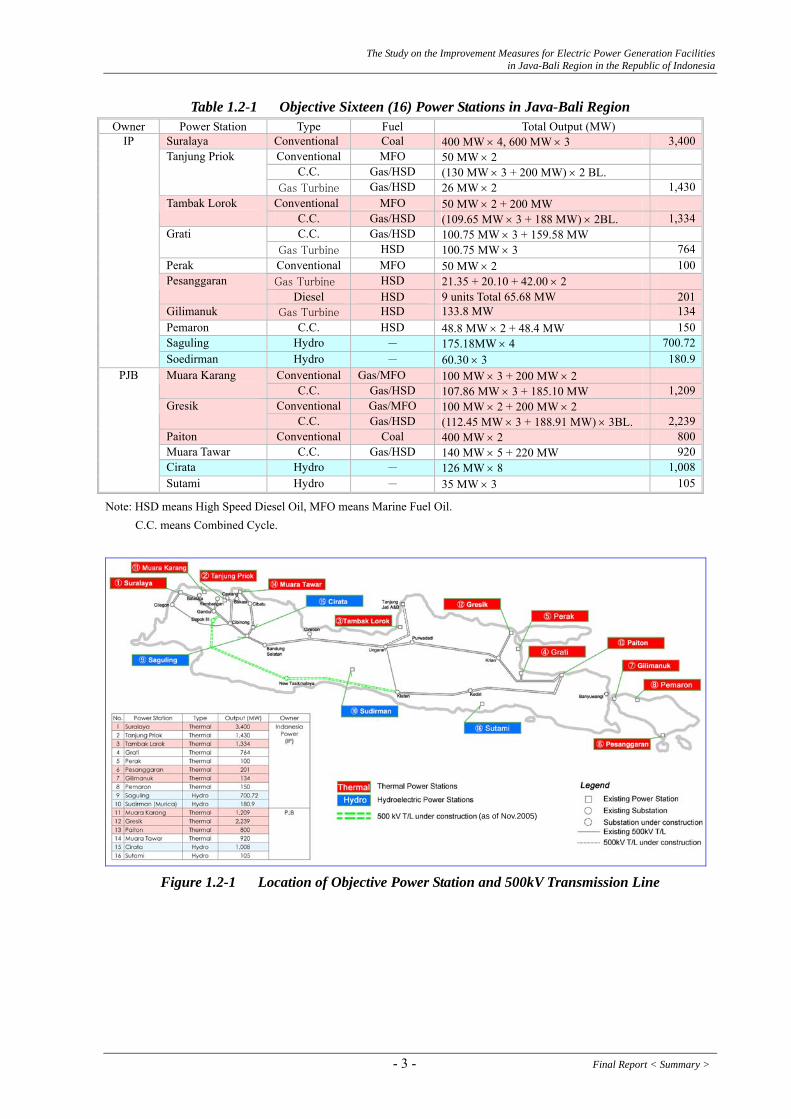
The objective power stations are the following sixteen (16) power stations in Java-Bali regions and their locations are figure below.
Final Report < Summary > - 2 -
The Study on the Improvement Measures for Electric Power Generation Facilities in Java-Bali Region in the Republic of Indonesia
Table 1.2-1 Objective Sixteen (16) Power Stations in Java-Bali Region Owner Power Station Type Fuel Total Output (MW)
Suralaya Conventional Coal 400 MW × 4, 600 MW × 3 3,400Conventional MFO 50 MW × 2
C.C. Gas/HSD (130 MW × 3 + 200 MW) × 2 BL. Tanjung Priok
Gas Turbine Gas/HSD 26 MW × 2 1,430Conventional MFO 50 MW × 2 + 200 MW Tambak Lorok
C.C. Gas/HSD (109.65 MW × 3 + 188 MW) × 2BL. 1,334C.C. Gas/HSD 100.75 MW × 3 + 159.58 MW Grati
Gas Turbine HSD 100.75 MW × 3 764Perak Conventional MFO 50 MW × 2 100
Gas Turbine HSD 21.35 + 20.10 + 42.00 × 2 Pesanggaran Diesel HSD 9 units Total 65.68 MW 201
Gilimanuk Gas Turbine HSD 133.8 MW 134Pemaron C.C. HSD 48.8 MW × 2 + 48.4 MW 150Saguling Hydro - 175.18MW × 4 700.72
IP
Soedirman Hydro - 60.30 × 3 180.9Conventional Gas/MFO 100 MW × 3 + 200 MW × 2 Muara Karang
C.C. Gas/HSD 107.86 MW × 3 + 185.10 MW 1,209Conventional Gas/MFO 100 MW × 2 + 200 MW × 2 Gresik
C.C. Gas/HSD (112.45 MW × 3 + 188.91 MW) × 3BL. 2,239Paiton Conventional Coal 400 MW × 2 800Muara Tawar C.C. Gas/HSD 140 MW × 5 + 220 MW 920Cirata Hydro - 126 MW × 8 1,008
PJB
Sutami Hydro - 35 MW × 3 105
Note: HSD means High Speed Diesel Oil, MFO means Marine Fuel Oil. C.C. means Combined Cycle.
(as of Nov.2005)
Figure 1.2-1 Location of Objective Power Station and 500kV Transmission Line
- 3 - Final Report < Summary >

The Study on the Improvement Measures for Electric Power Generation Facilities in Java-Bali Region in the Republic of Indonesia
1.3.2. Scope of Work
The Study is to develop the improvement measures relating to the existing power facilities and operation and maintenance based on the analyses of current situation of the objective power stations in order to reduce the gap between the installed capacity (total rated capacity: approximately 19,500 MW) and available power supply capacity (approximately 14,500 MW), which is regarded as the cause of tight of power balance and accounted to about 5,000 MW (26 % of total installed capacity). The Study is consisted of the following scope of work.
(1) Preliminary Survey Stage
The following survey will be carried out, in order to confirm the current situation of each power facilities in Java-Bali region.
1) Collection of data and information of the following items through the investigation of the relevant organization in Indonesia and electric power facilities in Java-Bali Region a) Performance of power generation facilities b) Current situation of operation, maintenance and inspection c) Organization and regulation for operation, maintenance and inspection d) Needs for the technology transfer on operation, maintenance and inspection e) 500 kV transmission line of Java-Bali system f) Plan of fuel supply
2) Review of the related reports and other relevant information
(2) Analysis and Examination Stage
Based on the result of the Preliminary Survey Stage, current situation and management system would be analyzed for each power generation facilities and necessary countermeasures would be examined. The following items will be considered in each power generation facilities. 1) Improvement measures of power generation facilities including rehabilitation,
modification and re-powering 2) Improvement measures of management for operation, maintenance and inspection 3) Economic and financial analysis of the above mentioned improvement 4) Grading the power facilities in need of improvement
(3) Technology Transfer Stage
Based on the impact and the needs for the technology transfer on operation, maintenance and inspection with are confirmed in the Preliminary Survey Stage, technology transfer on operation, maintenance and inspection will be conducted at the time of maintenance and inspection.
Final Report < Summary > - 4 -

The Study on the Improvement Measures for Electric Power Generation Facilities in Java-Bali Region in the Republic of Indonesia
(4) Recommendation Stage
Considering the results of the above mentioned stages, the following plan and recommendation will be submitted. 1) Rehabilitation, modification, or re-powering plan of the power generation facilities 2) Management plan and general guidelines of operation, maintenance and inspection 3) Recommendation to the organization and regulation for enhancing the capability of
operation, maintenance and inspection 4) Development plan of human resources for operation, maintenance and inspection
- 5 - Final Report < Summary >
The Study on the Improvement Measures for Electric Power Generation Facilities in Java-Bali Region in the Republic of Indonesia
2. Recognition of Current Situation in Java-Bali Region 2.1. Confirmation of Power Development Plan
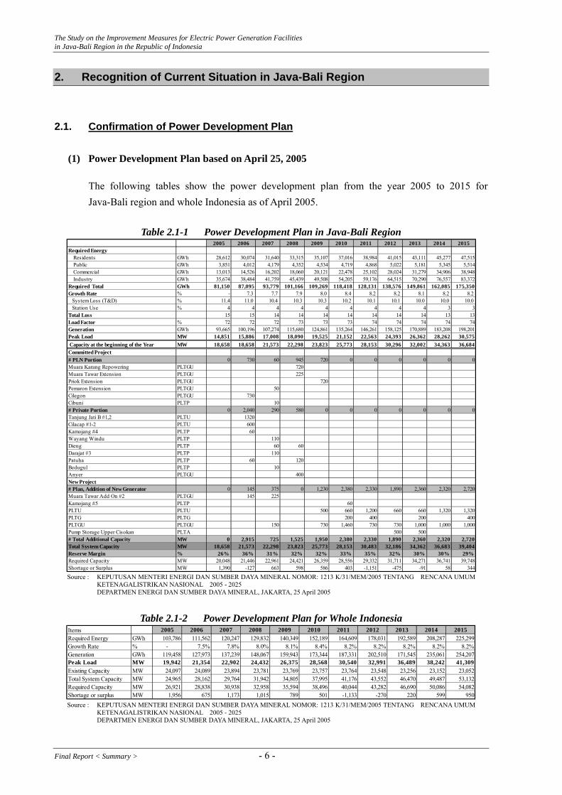
(1) Power Development Plan based on April 25, 2005
The following tables show the power development plan from the year 2005 to 2015 for Java-Bali region and whole Indonesia as of April 2005.
Table 2.1-1 Power Development Plan in Java-Bali Region
2005 2006 2007 2008 2009 2010 2011 2012 2013 2014 2015Required Energy Residents GWh 28,612 30,074 31,640 33,315 35,107 37,016 38,984 41,015 43,111 45,277 47,515 Public GWh 3,851 4,012 4,179 4,352 4,534 4,719 4,868 5,022 5,181 5,345 5,514 Commercial GWh 13,013 14,526 16,202 18,060 20,121 22,478 25,102 28,024 31,279 34,906 38,948 Industry GWh 35,674 38,484 41,759 45,439 49,508 54,205 59,176 64,515 70,290 76,557 83,372Required Total GWh 81,150 87,095 93,779 101,166 109,269 118,418 128,131 138,576 149,861 162,085 175,350Growth Rate % - 7.3 7.7 7.9 8.0 8.4 8.2 8.2 8.1 8.2 8. System Loss (T&D) % 11.4 11.0 10.4 10.3 10.3 10.2 10.1 10.1 10.0 10.0 10.0 Station Use % 4 4 4 4 4 4 4 4 4 3Total Loss 15 15 14 14 14 14 14 14 14 13 13Load Factor % 72 72 72 73 73 73 74 74 74 74 7Generation GWh 93,665 100,196 107,274 115,680 124,861 135,264 146,261 158,125 170,889 183,208 198,201Peak Load MW 14,851 15,886 17,008 18,090 19,525 21,152 22,563 24,393 26,362 28,262 30,575 Capacity at the beginning of the Year MW 18,658 18,658 21,573 22,298 23,823 25,773 28,153 30,296 32,002 34,363 36,684Committed Project# PLN Portion 0 730 60 945 720 0 0 0 0 0Muara Karang Repowering PLTGU 720Muara Tawar Extension PLTGU 225Priok Extension PLTGU 720Pemaron Extension PLTGU 50Cilegon PLTGU 730Cibuni PLTP 10# Private Portion 0 2,040 290 580 0 0 0 0 0 0Tanjung Jati B #1,2 PLTU 1320Cilacap #1-2 PLTU 600Kamojang #4 PLTP 60Wayang Windu PLTP 110Dieng PLTP 60 60Darajat #3 PLTP 110Patuha PLTP 60 120Bedugul PLTP 10Anyer PLTGU 400New Project# Plan, Addition of New Generator 0 145 375 0 1,230 2,380 2,330 1,890 2,360 2,320 2,720Muara Tawar Add On #2 PLTGU 145 225Kamojang #5 PLTP 60PLTU PLTU 500 660 1,200 660 660 1,320 1,320PLTG PLTG 200 400 200 400PLTGU PLTGU 150 730 1,460 730 730 1,000 1,000 1,000Pump Storage Upper Cisokan PLTA 500 500# Total Additional Capacity MW 0 2,915 725 1,525 1,950 2,380 2,330 1,890 2,360 2,320 2,720Total System Capacity MW 18,658 21,573 22,298 23,823 25,773 28,153 30,483 32,186 34,362 36,683 39,404Reserve Margin % 26% 36% 31% 32% 32% 33% 35% 32% 30% 30% 29%Required Capacity MW 20,048 21,446 22,961 24,421 26,359 28,556 29,332 31,711 34,271 36,741 39,748Shortage or Surplus MW 1,390 -127 663 598 586 403 -1,151 -475 -91 58 344
2
3
4
0
0
Source : KEPUTUSAN MENTERI ENERGI DAN SUMBER DAYA MINERAL NOMOR: 1213 K/31/MEM/2005 TENTANG RENCANA UMUM
KETENAGALISTRIKAN NASIONAL 2005 - 2025 DEPARTMEN ENERGI DAN SUMBER DAYA MINERAL, JAKARTA, 25 April 2005
Table 2.1-2 Power Development Plan for Whole Indonesia
Items 2005 2006 2007 2008 2009 2010 2011 2012 2013 2014 2015Required Energy GWh 103,786 111,562 120,247 129,832 140,349 152,189 164,609 178,031 192,589 208,287 225,299Growth Rate % - 7.5% 7.8% 8.0% 8.1% 8.4% 8.2% 8.2% 8.2% 8.2% 8.2%Generation GWh 119,458 127,973 137,239 148,067 159,943 173,344 187,331 202,510 171,545 235,061 254,207Peak Load MW 19,942 21,354 22,902 24,432 26,375 28,568 30,540 32,991 36,489 38,242 41,309Existing Capacity MW 24,097 24,089 23,894 23,781 23,769 23,757 23,764 23,548 23,256 23,152 23,052Total System Capacity MW 24,965 28,162 29,764 31,942 34,805 37,995 41,176 43,552 46,470 49,487 53,132Required Capacity MW 26,921 28,838 30,938 32,958 35,594 38,496 40,044 43,282 46,690 50,086 54,082Shortage or surplus MW 1,956 675 1,173 1,015 789 501 -1,133 -270 220 599 950 Source : KEPUTUSAN MENTERI ENERGI DAN SUMBER DAYA MINERAL NOMOR: 1213 K/31/MEM/2005 TENTANG RENCANA UMUM
KETENAGALISTRIKAN NASIONAL 2005 - 2025 DEPARTMEN ENERGI DAN SUMBER DAYA MINERAL, JAKARTA, 25 April 2005
Final Report < Summary > - 6 -

The Study on the Improvement Measures for Electric Power Generation Facilities in Java-Bali Region in the Republic of Indonesia
Referring to the above tables, the following findings are observed.
a) The Indonesian Government (MEMR) forecasts 7 ~ 8% of the growth rate for power demand in Java-Bali region and whole Indonesia.
b) The peak demand in the year 2010, five (5) years later, is estimated to 21,152 MW in Java-Bali region and 42 % more in comparison with 14,851 MW in the year 2005. To meet the peak demand in the year 2010, the new power stations and/or re-powering projects will be intensively implemented in the next four years from the year 2006. Since the most projects for the next four (4) years are committed projects, the materialization of the power development program is well expected.
c) Since there are not committed projects after the year 2010, the Indonesian Government has to prepare the concrete power development projects in cooperation with PLN in the next few years taken account of the long lead time for power source development.
(2) Crash Program for New Coal-fired Thermal Power Stations
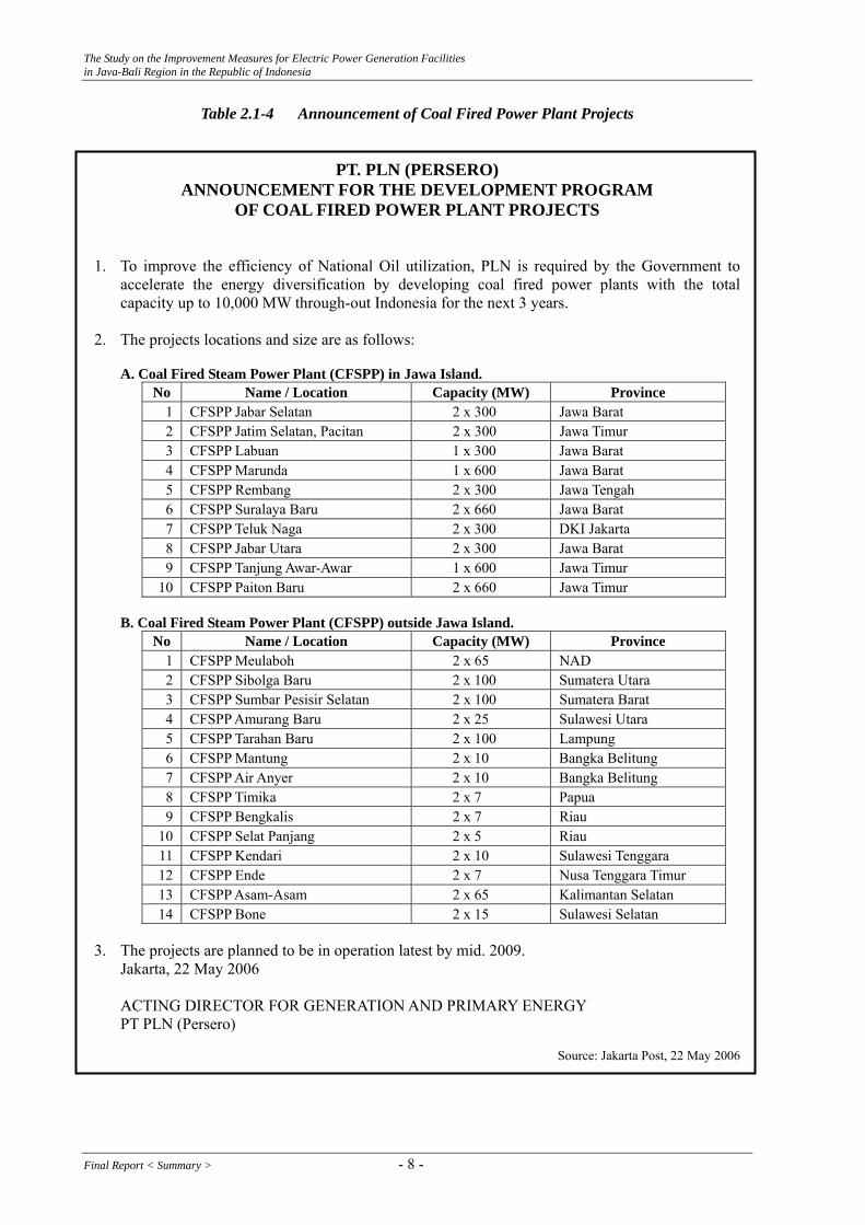
PLN has announced the development program of new coal fired thermal power plant projects to the amount of 10,000 MW within next three years on May 22, 2006 as shown blow. The purpose of the implementation of new coal fired thermal stations is to promote the diversification of energy, in other words, to cut the current expensive oil fuel according to the newspaper. In this connection, the Presidential Decree No. 71 (Team Formation) and No. 72 (List of Projects) was issued.
The Jakarta Post said “It expects that by 2010, the use of expensive fuel-fired power plants will be reduced to just 5 percent of total capacity from the current 30 percent, which would cut costs by as much as 80 percent.1” In line with the new crash program, MEMR has been revising the national power development plan (2006 ~ 2026) accordingly and released on June 30, 2006. The existing oil-fired power stations are more likely to be affected by the crash program in some way.
1 Jakarta post, July 21, 2006
- 7 - Final Report < Summary >
The Study on the Improvement Measures for Electric Power Generation Facilities in Java-Bali Region in the Republic of Indonesia
Table 2.1-4 Announcement of Coal Fired Power Plant Projects
PT. PLN (PERSERO) ANNOUNCEMENT FOR THE DEVELOPMENT PROGRAM
OF COAL FIRED POWER PLANT PROJECTS
1. To improve the efficiency of National Oil utilization, PLN is required by the Government to accelerate the energy diversification by developing coal fired power plants with the total capacity up to 10,000 MW through-out Indonesia for the next 3 years.
2. The projects locations and size are as follows:
A. Coal Fired Steam Power Plant (CFSPP) in Jawa Island. No Name / Location Capacity (MW) Province
1 CFSPP Jabar Selatan 2 x 300 Jawa Barat 2 CFSPP Jatim Selatan, Pacitan 2 x 300 Jawa Timur 3 CFSPP Labuan 1 x 300 Jawa Barat 4 CFSPP Marunda 1 x 600 Jawa Barat 5 CFSPP Rembang 2 x 300 Jawa Tengah 6 CFSPP Suralaya Baru 2 x 660 Jawa Barat 7 CFSPP Teluk Naga 2 x 300 DKI Jakarta 8 CFSPP Jabar Utara 2 x 300 Jawa Barat 9 CFSPP Tanjung Awar-Awar 1 x 600 Jawa Timur
10 CFSPP Paiton Baru 2 x 660 Jawa Timur
B. Coal Fired Steam Power Plant (CFSPP) outside Jawa Island. No Name / Location Capacity (MW) Province
1 CFSPP Meulaboh 2 x 65 NAD 2 CFSPP Sibolga Baru 2 x 100 Sumatera Utara 3 CFSPP Sumbar Pesisir Selatan 2 x 100 Sumatera Barat 4 CFSPP Amurang Baru 2 x 25 Sulawesi Utara 5 CFSPP Tarahan Baru 2 x 100 Lampung 6 CFSPP Mantung 2 x 10 Bangka Belitung 7 CFSPP Air Anyer 2 x 10 Bangka Belitung 8 CFSPP Timika 2 x 7 Papua 9 CFSPP Bengkalis 2 x 7 Riau
10 CFSPP Selat Panjang 2 x 5 Riau 11 CFSPP Kendari 2 x 10 Sulawesi Tenggara 12 CFSPP Ende 2 x 7 Nusa Tenggara Timur 13 CFSPP Asam-Asam 2 x 65 Kalimantan Selatan 14 CFSPP Bone 2 x 15 Sulawesi Selatan
3. The projects are planned to be in operation latest by mid. 2009. Jakarta, 22 May 2006
ACTING DIRECTOR FOR GENERATION AND PRIMARY ENERGY PT PLN (Persero)
Source: Jakarta Post, 22 May 2006
Final Report < Summary > - 8 -

The Study on the Improvement Measures for Electric Power Generation Facilities in Java-Bali Region in the Republic of Indonesia
(3) Expansion Plan for the Transmission Lines and Transformers in Ten Years
The expansion plans of 500 kV transmission line and 500 kV substation in ten years are shown in the following tables. 3,399 km transmission lines and 18,998 MVA transformers will be constructed in the next decade.
Expansion Plan of 500 kV Transmission Line (km)
2006 2007 2008 2009 2010 2011 2012 2013 2014 2015
861 178 280 250 110 920 356 - - 444
Expansion Plan of 500 kV Transformer (MVA)
2006 2007 2008 2009 2010 2011 2012 2013 2014 2015
3,498 3,000 - 1,000 500 2,500 2,000 2,000 1,500 3,000
Source; Rencana Usaha Penyediaan Tenaga Listrik 2006-2015
(4) Southern 500 kV Transmission Line (including Substation)
In order to supply from the eastern part which has a lot of power sources to the western part in Java including Jakarta which is the biggest demand area, it is necessary to solve the problem of system stability (Section 3.3.1) in Java-Bali system and to improve the reliability. That is why southern 500 kV transmission line from Paiton P/S to Depok III S/S2 through Kediri S/S, Klaten S/S, and Tasikmalaya S/S is under construction as shown in the following figure.
The section from Paiton P/S to Klaten S/S was already constructed and is in operation as of November 2005. But the one from Klaten S/S to Depok III has not connected yet. 90% and more of construction works are completed, but construction works such as transmission lines around Depok III S/S are delayed because of the difficulties of the land acquisition around the area. This southerly transmission line will be operated by the end of 2006.
2 The construction of southern 500kV transmission line was completed in June 2006.
- 9 - Final Report < Summary >

The Study on the Improvement Measures for Electric Power Generation Facilities in Java-Bali Region in the Republic of Indonesia
(as of Nov.2005)
Figure 2.1-1 Southerly 500 kV Transmission Line
(5) Java-Sumatera Interconnection Project
According to RUPTL, a coal fired power plant will be constructed in Mulut Tamgbang, Sumatera. The total capacity is planned as 2,400 MW (600 MW × 2 in 2010 and 600 MW × 2 in 2011). 400 MW of the planned capacity will be supplied inside Sumatera and the rest 2,000 MW will be transmitted to Java-Bali System. As one of the methods of supply from Sumatera to Java, there is a plan as follows;
(6) Java-Bali Interconnection Project
According to RUPTL, in Bali Island the total supply capacity of the existing generators and newly installed generators, considering supply from Java Island, will reach 874 MW in 2008. But in the future the amount of demand will exceed the total supply capacity because the demand will be expected to highly increase. Therefore, the new 500 kV transmission line will be constructed between Paiton substation in Java and newly installed Kapal substation in Bali in order to strengthen the system interconnection. As a result the supply capacity is enough for the demand in Bali as of 2015. Hereafter a further study is necessary in accordance with the power development plan including the repowering plan of the existing generators which is recommended in this report.
Since a coal fired power station with 3 × 130 MW (Celukan Bawang (Northern part of Bali)) will be operated in 2009 and 2010 and a coal fired thermal power station with 2 x 100 MW (Eastern part of Bali) based on the infrastructure project will be operated in 2012, the Java-Bali Interconnection project will be after the implementation of these coal fired power stations.
Now PLN has been conducting pre-F/S on a coal fired thermal power station in Nusa Penida located at South of Bali Island.
Final Report < Summary > - 10 -

The Study on the Improvement Measures for Electric Power Generation Facilities in Java-Bali Region in the Republic of Indonesia
2.2. Confirmation of Fuel Supply Plan 2.2.1. Fuel Oil Prices
The trend of fuel oil prices relating to MFO and HSD, which are used in power stations, for the period from February 2003 to April 2006, are shown in the figure below. As shown in the figure, fuel prices have skyrocketed in 2005 in line with the rise of crude oil worldwide. Since China, which had been one of the exporters of oil, is a oil importer substantially according to her sharp economic growth, the high fuel prices might be continued for some time. As of April 2006, the fuel prices for MFO and HSD have not been accompanied by any subsidies.
1,65
0 2,05
02,
050
2,03
01,
790
1,70
01,
710
1,88
01,
950
1,89
01,
990
2,05
02,
050
2,05
02,
050
2,05
02,
050
2,05
02,
050
2,05
02,
050
2,05
02,
050
2,05
02,
050 2,
660
2,66
0
5,24
05,
130
5,13
0 5,78
05,
940
5,18
04,
810
5,02
04,
900
4,98
3
1,56
01,
600
1,60
01,
580
1,56
01,
560
1,57
01,
600
1,56
01,
890
1,56
01,
560
1,56
01,
560
1,56
01,
590
1,60
01,
600
1,60
01,
600
1,60
01,
600
1,60
01,
600
1,60
02,
300
2,30
0 2,90
03,
150
3,15
03,
150
3,81
03,
870
3,68
03,
480
3,38
03,
603
3,67
2
4,56
0
0
1,000
2,000
3,000
4,000
5,000
6,000
7,000
03.0
2.01
03.0
4.01
03.0
6.01
03.0
8.01
03.1
0.01
03.1
2.01
04.0
2.01
04.0
4.01
04.0
6.01
04.0
8.01
04.1
0.01
04.1
2.01
05.0
2.01
05.0
4.01
05.0
8.01
05.1
0.01
05.1
1.01
06.0
1.01
06.0
3.01
Date(yy/mm/dd)
Fuel
Pri
ce (R
p/L
iter)
HSD MFOSource: PERTAMINA
Figure 2.2-1 Trend of Fuel Oil Prices for HSD and MFO
2.2.2. Natural Gas
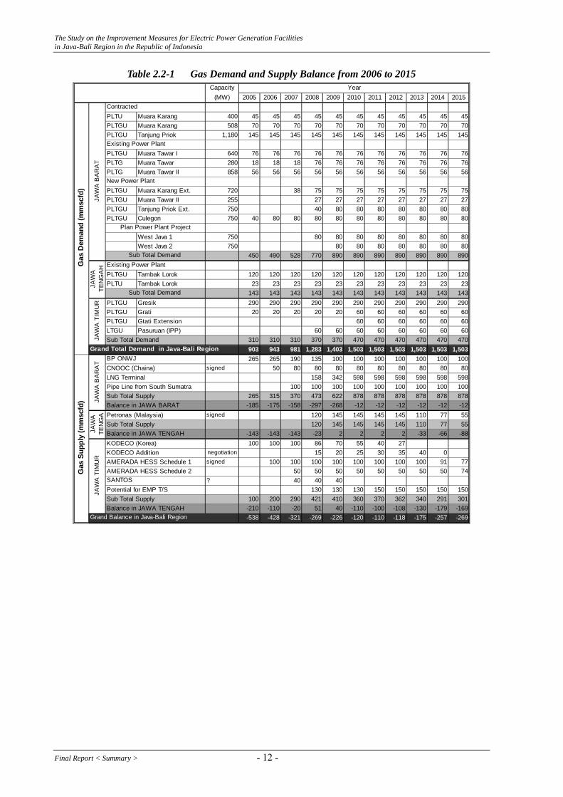
Table 2.2-1 shows the future gas demand and supply plan in Java-Bali region for the period from 2006 to 2015 as of August 2006 provided by PLN. However, the gas demand and supply plan does not reflect the actual situation. For example, Muara Tawar Block 1 & 2, Grati, Pesanggaran, Pemaron and Gilimanuk could use gas from the year 2006, although they are still forced to use oil as of July 2006. Measures for the shortage of gas supply as far as PLN concerned seem to be two alternatives. One is to cut the gas supply to power stations, the other is to request BPMIGAS, which is the government agency under the president’s direct control and have the power to supervise the business activities relating to gas, to allocate more gas to Power Sector. At the moment PLN seems to be forced to select the former option in a short term even though the additional efforts are made as described in Section 2.2.3. The following table is reference only because gas supply is out of control of PLN.
- 11 - Final Report < Summary >
The Study on the Improvement Measures for Electric Power Generation Facilities in Java-Bali Region in the Republic of Indonesia
Table 2.2-1 Gas Demand and Supply Balance from 2006 to 2015 Capacity
(MW) 2005 2006 2007 2008 2009 2010 2011 2012 2013 2014 2015
PLTU Muara Karang 400 45 45 45 45 45 45 45 45 45 45 45PLTGU Muara Karang 508 70 70 70 70 70 70 70 70 70 70 70PLTGU Tanjung Priok 1,180 145 145 145 145 145 145 145 145 145 145 145
PLTGU Muara Tawar I 640 76 76 76 76 76 76 76 76 76 76 76PLTG Muara Tawar 280 18 18 18 76 76 76 76 76 76 76 76PLTG Muara Tawar II 858 56 56 56 56 56 56 56 56 56 56 56
PLTGU Muara Karang Ext. 720 38 75 75 75 75 75 75 75 75PLTGU Muara Tawar II 255 27 27 27 27 27 27 27 27PLTGU Tanjung Priok Ext. 750 40 80 80 80 80 80 80 80PLTGU Culegon 750 40 80 80 80 80 80 80 80 80 80 80
West Java 1 750 80 80 80 80 80 80 80 80West Java 2 750 80 80 80 80 80 80 80
450 490 528 770 890 890 890 890 890 890 890
PLTGU Tambak Lorok 120 120 120 120 120 120 120 120 120 120 120PLTU Tambak Lorok 23 23 23 23 23 23 23 23 23 23 23
143 143 143 143 143 143 143 143 143 143 143PLTGU Gresik 290 290 290 290 290 290 290 290 290 290 290PLTGU Grati 20 20 20 20 20 60 60 60 60 60 60PLTGU Gtati Extension 60 60 60 60 60 60LTGU Pasuruan (IPP) 60 60 60 60 60 60 60 60Sub Total Demand 310 310 310 370 370 470 470 470 470 470 470
903 943 981 1,283 1,403 1,503 1,503 1,503 1,503 1,503 1,503265 265 190 135 100 100 100 100 100 100 100
CNOOC (Chaina) signed 50 80 80 80 80 80 80 80 80 80LNG Terminal 158 342 598 598 598 598 598 598Pipe Line from South Sumatra 100 100 100 100 100 100 100 100 100Sub Total Supply 265 315 370 473 622 878 878 878 878 878 878Balance in JAWA BARAT -185 -175 -158 -297 -268 -12 -12 -12 -12 -12 -12Petronas (Malaysia) signed 120 145 145 145 145 110 77 55Sub Total Supply 120 145 145 145 145 110 77 55Balance in JAWA TENGAH -143 -143 -143 -23 2 2 2 2 -33 -66 -88KODECO (Korea) 100 100 100 86 70 55 40 27 KODECO Addition negotiation 15 20 25 30 35 40 0AMERADA HESS Schedule 1 signed 100 100 100 100 100 100 100 100 91 77AMERADA HESS Schedule 2 50 50 50 50 50 50 50 50 74
? 40 40 40Potential for EMP T/S 130 130 130 150 150 150 150 150Sub Total Supply 100 200 290 421 410 360 370 362 340 291 301Balance in JAWA TENGAH -210 -110 -20 51 40 -110 -100 -108 -130 -179 -169
-538 -428 -321 -269 -226 -120 -110 -118 -175 -257 -269
Gas
Sup
ply
(mm
scfd
)
BP ONWJ
SANTOS
Grand Balance in Java-Bali Region
JAW
A T
IMU
RJA
WA
BA
RA
TJA
WA
TEN
GA
Year
Existing Power Plant
Sub Total Demand
JAW
ATE
NG
AHG
as D
eman
d (m
msc
fd)
Grand Total Demand in Java-Bali Region
Contracted
Existing Power Plant
New Power Plant
JAW
A T
IMU
R
Plan Power Plant Project
Sub Total Demand
JAW
A B
AR
AT
Final Report < Summary > - 12 -
The Study on the Improvement Measures for Electric Power Generation Facilities in Java-Bali Region in the Republic of Indonesia
2.3. Confirmation of Financial Status of PLN and Power Generation Companies
(1) PLN
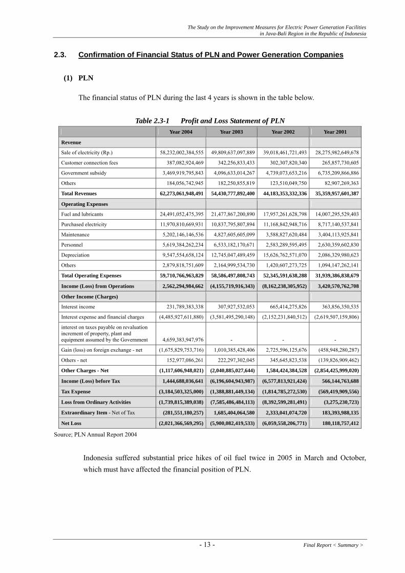
The financial status of PLN during the last 4 years is shown in the table below.
Table 2.3-1 Profit and Loss Statement of PLN Year 2004 Year 2003 Year 2002 Year 2001
Revenue
Sale of electricity (Rp.) 58,232,002,384,555 49,809,637,097,889 39,018,461,721,493 28,275,982,649,678
Customer connection fees 387,082,924,469 342,256,833,433 302,307,820,340 265,857,730,605
Government subsidy 3,469,919,795,843 4,096,633,014,267 4,739,073,653,216 6,735,209,866,886
Others 184,056,742,945 182,250,855,819 123,510,049,750 82,907,269,363
Total Revenues 62,273,061,948,491 54,430,777,892,400 44,183,353,332,336 35,359,957,601,387
Operating Expenses
Fuel and lubricants 24,491,052,475,395 21,477,867,200,890 17,957,261,628,798 14,007,295,529,403
Purchased electricity 11,970,810,669,931 10,837,795,807,894 11,168,842,948,716 8,717,140,537,841
Maintenance 5,202,146,146,536 4,827,605,605,099 3,588,827,620,484 3,404,113,925,841
Personnel 5,619,384,262,234 6,533,182,170,671 2,583,289,595,495 2,630,359,602,830
Depreciation 9,547,554,658,124 12,745,047,489,459 15,626,762,571,070 2,086,329,980,623
Others 2,879,818,751,609 2,164,999,534,730 1,420,607,273,725 1,094,147,262,141
Total Operating Expenses 59,710,766,963,829 58,586,497,808,743 52,345,591,638,288 31,939,386,838,679
Income (Loss) from Operations 2,562,294,984,662 (4,155,719,916,343) (8,162,238,305,952) 3,420,570,762,708
Other Income (Charges)
Interest income 231,789,383,338 307,927,532,053 665,414,275,826 363,856,350,535
Interest expense and financial charges (4,485,927,611,880) (3,581,495,290,148) (2,152,231,840,512) (2,619,507,159,806)
interest on taxes payable on revaluation increment of property, plant and equipment assumed by the Government 4,659,383,947,976 - - -
Gain (loss) on foreign exchange - net (1,675,829,753,716) 1,010,385,428,406 2,725,596,125,676 (458,948,280,287)
Others - net 152,977,086,261 222,297,302,045 345,645,823,538 (139,826,909,462)
Other Charges - Net (1,117,606,948,021) (2,040,885,027,644) 1,584,424,384,528 (2,854,425,999,020)
Income (Loss) before Tax 1,444,688,036,641 (6,196,604,943,987) (6,577,813,921,424) 566,144,763,688
Tax Expense (3,184,503,325,000) (1,388,881,449,134) (1,814,785,272,530) (569,419,909,556)
Loss from Ordinary Activities (1,739,815,389,038) (7,585,486,484,113) (8,392,599,281,491) (3,275,230,723)
Extraordinary Item - Net of Tax (281,551,180,257) 1,685,404,064,580 2,333,041,074,720 183,393,988,135
Net Loss (2,021,366,569,295) (5,900,082,419,533) (6,059,558,206,771) 180,118,757,412
Source; PLN Annual Report 2004
Indonesia suffered substantial price hikes of oil fuel twice in 2005 in March and October, which must have affected the financial position of PLN.
- 13 - Final Report < Summary >
The Study on the Improvement Measures for Electric Power Generation Facilities in Java-Bali Region in the Republic of Indonesia
2.4. Review of Collected Data and Information Relating to Technology Transfer
(1) Thermal Power Station
Remaining Life Assessment carried out in Indonesia seems to be different from that of Japan. Remaining Life Assessment in Japan is used for the assessments whether a power station operated more than 20 years is still operational and whether the interval of periodical inspection for the power station is changeable from once two years to once four years from the viewpoint of the reliability. On the other hand, Remaining Life Assessment in Indonesia seems to be similar with the so-called “Equipment Diagnosis”, which has been conducted in a periodical inspection in Japan. And concerning the frequency of outages of power stations, number of outages in Japan is less than that of Indonesia because the technical standards oblige to replace the relevant component before the occurrence of serious abrasion of thickness in Japan.
1) Concerning a boiler, LITBANG has conducted Remaining Life Assessment by his manner and tubes for SH (Super Heater), RH (Re-heater), and WW (Water Wall), where happened abrasion of thickness, have been replaced sequentially. For Paiton unit 1 & 2, some countermeasures seem to be necessary because a number of times of steam leakage have happened at the same portion.
2) Relating to a turbine body, Remaining Life Assessment has not been conducted by PLN. Instead of PLN, a manufacturer has conducted Remaining Life Assessment and reported (Suralaya unit 2). The Study Team received the report. For Gresik unit 4, sea water leakage at a condenser tube has happened repeatedly and damage at the final stage of low pressure turbine probably caused by Cl included in sea water was observed.
3) Relating to a generator, for Suralaya unit 2, deterioration of electrical insulation for the stator is reported by a manufacturer. The evaluation of the material used for the insulator seems to be necessary.
(2) Hydropower Station
In the course of the 1st Field Work, the current situation and the necessity relating to Remaining Life Assessment, such as “Nondestructive Examination” and “Electrical Insulation Examination for the generator stator winding” mainly, were investigated for objective four (4) hydropower stations and the researching institute of PLN (LITBANG).
Based on the results of the 1st Field Work, it can be said that Remaining Life Assessment utilizing a nondestructive examination and an electrical insulation examination for hydro power stations has not been conducted basically. However, the relevant personnel showed strong concerns and well understand the necessity and effect. Therefore, the introduction of Remaining Life Assessment to hydro power stations is well advisable form the viewpoint of
Final Report < Summary > - 14 -

The Study on the Improvement Measures for Electric Power Generation Facilities in Java-Bali Region in the Republic of Indonesia
preventive maintenance expected to reduce serious accidents.
For the above reasons, related technologies for a nondestructive examination and an electric insulation examination for generator stator winding are proposed at present as Technology Transfer relating to Remaining Life Assessment for the purpose of further rooting the concept of preventive maintenance in Indonesia.
More specific items for Technology Transfer are as follows at the moment:
(a) Remaining Life Assessment by using the nondestructive examination results for a casing and a stay vane
(b) Remaining Life Assessment by using the management of welding volume for the turbine runner
(c) Remaining Life Assessment by using the results of electrical insulation examination for the generator stator winding
2.5. Current Status of JBIC Export Credit
A rehabilitation plan of PLN for application to JBIC Export Credit Line, which was disclosed to JICA Study Team during the 1st Field Investigation, is as follows.
(1) Muara Karang Thermal Power Plant Units No. 4 and No. 5
Output : 422 MW (2 × 211 MW) Initial Commercial Operation : Unit No. 4 (1981), Unit No. 5(1982) Original Supplier : Mitsubishi Heavy Industries Estimated Cost for Rehab. : Phase I (US$ 112 Million), Phase II (US$ 36 Million) Proposed Rehabilitation : Replacement air preheater (AH) and GRF, etc.
(2) Suralaya Thermal Power Plant Units No. 1 through No. 4
Output : 1,680 MW (4 × 420 MW) Initial Commercial Operation : Unit No. 1 (1984), No. 2 (1985), No. 3 (1988) and No. 4 (1989) Original Supplier : Mitsubishi Heavy Industries Estimated Cost for Rehab. : US$ 201Million Proposed Rehabilitation : Replacement 2nd superheater and reheater outlet, etc.
(3) Paiton Thermal Power Plant Units No. 1 and No. 2
Output : 806.25 MW (2 × 403.25 MW) Initial Commercial Operation : Unit No. 1 (1994), Unit No. 2(1993) Original Supplier : Alstom and Toshiba Estimated Cost for Rehab. : US$ 44 Million Proposed Rehabilitation : Replacement of labyrinth and modification of boiler, etc.
- 15 - Final Report < Summary >

The Study on the Improvement Measures for Electric Power Generation Facilities in Java-Bali Region in the Republic of Indonesia
(4) Saguling Hydro Power Plant Units No. 1 through No. 4 Output : 700MW (4 × 175MW) Initial Commercial Operation : Units No. 1/No. 2 (1985)、Units No.3/No. 4(1986) Original Supplier : Toshiba Estimated Cost for Rehab. : US$ 23Million Proposed Rehabilitation : Replacement of turbine runner and governor system, etc.
Indonesia Power gives importance to Saguling Rehabilitation Project as a pilot project utilizing JBIC Export Credit Line, and they have a strong wish to implement rehabilitation of the Soedirman Hydro Power Plant using the same scheme of JBIC, if the Saguling rehabilitation is completed successfully in both technical and financial view points. As of July 2006, recommendation letters for Suralaya and Muara Karang were submitted from BAPPENAS to the Ministry of Finance (MFO). According to PLN information, PLN intends to implement rehabilitation/modification works for Suralaya Power Station PLTU #3 & #4 and Muara Karang Power Station PLTU #4 & #5 by the next JBIC Export Credit Line, which were excluded from the above 1st credit line due to the limitation of Indonesia’s budget.
2.6. Confirmation of Environmental Regulation Relating for Power Sector
The Environmental and social consideration in Indonesia shall be carried out by a project owner/executor. Therefore, the environmental and social consideration relating to rehabilitation/modification and repowering plans proposed in the Study shall be done by the generation companies, which are the owner of the power generation facilities. MEMR, a governing legal authority of Energy Sector, has environment sections/teams for each energy related activities. For example, Deputy Director of Electricity Environmental Protection under the Director General Electricity and Energy Utilization is one the personnel in charge of environmental issues for Power Sector (refer to Figure 2.6-1). Environment sections/ teams fills a role of giving instructions and advices to power enterprises (power generation companies and IPP) relating to environmental issues including KA-ANDAL and AMDAL to be submitted to BAPEDALDA. Environmental issues relating to rehabilitation plan for a power station developed in the FS stage are accepted by the Deputy Director of Electricity Installation and Safety under the Director General Electricity and Energy Utilization.
Final Report < Summary > - 16 -

The Study on the Improvement Measures for Electric Power Generation Facilities in Java-Bali Region in the Republic of Indonesia
Figure 2.6-1(1) Organization Chart for Ministry Energy and Mineral Resources
- 17 - Final Report < Summary >
The Study on the Improvement Measures for Electric Power Generation Facilities in Java-Bali Region in the Republic of Indonesia
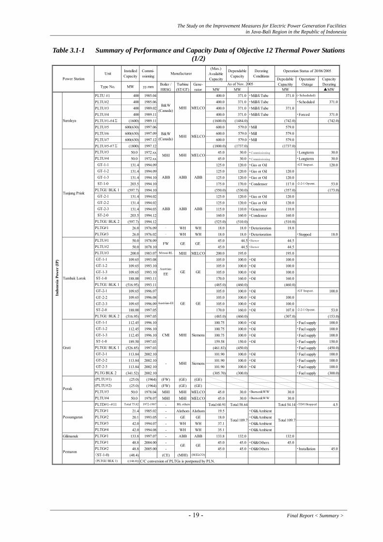
3. Review of Existing Electric Power Generation Facilities 3.1. Confirmation of Current Status and Issues Relating to Facilities 3.1.1. Thermal Power Stations 3.1.1.1. Overall Status and Issues of the Objective Twelve (12) Thermal Power Stations
The thermal team of the JICA Study Team visited and investigated the objective twelve (12) thermal power stations in Java-Bali region during the 1st Field Work from November 17 through December 15, 2005. The Study Team got and collected the huge volume of the operational data in the forms of hard copies or soft copies supplied by each power station. Thereafter, the Study Team visited some thermal power stations again in order to complement these data using the timings of the 2nd and 3rd Field Works. Then, it is noted that the figures of the total installed capacities of the objective thermal power stations have major difference between the Java-Bali region and our study of this time. Both figures of total installed capacities are compared as follows; Total Capacity Objective Capacity Thermal Power : 16,232 MW 12,660 MW Hydro Power : 2,548 MW 1,995 MW Geo-thermal Power : 754 MW - Total : 19,534 MW 14,655 MW
The operation status on 20/06/2005 causing the serious power supply shortage in Java-Bali region are listed in the Table 3.1-1 for the review of the requirements for the Study as to the requirements of capacity gain measures recovering performance deterioration for the thermal power stations.
Final Report < Summary > - 18 -
The Study on the Improvement Measures for Electric Power Generation Facilities in Java-Bali Region in the Republic of Indonesia
Table 3.1-1 Summary of Performance and Capacity Data of Objective 12 Thermal Power Stations (1/2)
MW MW MW ▲MWPLTU #1 400 1985.04 400.0 371.0 ・Mill&Tube 371.0 (・Scheduled)
PLTU#2 400 1985.06 400.0 371.0 ・Mill&Tube ・Scheduled 371.0PLTU#3 400 1989.02 400.0 371.0 ・Mill&Tube 371.0PLTU#4 400 1989.11 400.0 371.0 ・Mill&Tube ・Forced 371.0PLTU#1-#4∑ (1600) 1989.11 (1600.0) (1484.0) (742.0) (742.0)PLTU#5 600(630) 1997.06 600.0 579.0 ・Mill 579.0PLTU#6 600(630) 1997.09 600.0 579.0 ・Mill 579.0PLTU#7 600(630) 1997.12 600.0 579.0 ・Mill 579.0PLTU#5-#7∑ (1800) 1997.12 (1800.0) (1737.0) (1737.0)
50.0 1972.xx 45.0 30.0 ・Commissioning ・Longterm 30.050.0 1972.xx 45.0 30.0 ・Commissioning ・Longterm 30.0131.4 1994.09 125.0 120.0 ・Gas or Oil ・GT Inspect. 120.0131.4 1994.09 125.0 120.0 ・Gas or Oil 120.0131.4 1994.10 125.0 120.0 ・Gas or Oil 120.0203.5 1994.10 175.0 170.0 ・Condenser 117.0 ・2-2-1 Operat. 53.0
(597.7) 1994.10 (550.0) (530.0) (357.0) (173.0)131.4 1994.02 125.0 120.0 ・Gas or Oil 120.0131.4 1994.02 125.0 120.0 ・Gas or Oil 120.0131.4 1994.03 115.0 110.0 ・Generator 110.0203.5 1994.12 160.0 160.0 ・Condenser 160.0
(597.7) 1994.12 (525.0) (510.0) (510.0)26.0 1976.09 ‐ WH WH 18.0 18.0 ・Deterioration 18.026.0 1976.02 ‐ WH WH 18.0 18.0 ・Deterioration ・Stopped 18.050.0 1978.09 45.0 44.5 ・Burner 44.550.0 1078.10 45.0 44.5 ・Burner 44.5
200.0 1983.07 Mitsui-RL MHI MELCO 200.0 195.0 195.0109.65 1993.08 105.0 100.0 ・Oil 100.0109.65 1993.10 105.0 100.0 ・Oil 100.0109.65 1993.10 105.0 100.0 ・Oil 100.0188.00 1993.11 170.0 160.0 ・Oil 160.0
(516.95) 1993.11 (485.0) (460.0) (460.0)109.65 1996.07 105.0 100.0 ・Oil ・GT Inspect. 100.0
GT-2-2 109.65 1996.08 105.0 100.0 ・Oil 100.0 GT-2-3 109.65 1996.09 105.0 100.0 ・Oil 100.0
188.00 1997.05 170.0 160.0 ・Oil 107.0 ・2-2-1 Operat. 53.0(516.95) 1997.05 (485.0) (460.0) (307.0) (153.0)
112.45 1996.10 100.75 100.0 ・Oil ・Fuel supply 100.0112.45 1996.10 100.75 100.0 ・Oil ・Fuel supply 100.0112.45 1996.10 100.75 100.0 ・Oil ・Fuel supply 100.0189.50 1997.03 159.58 150.0 ・Oil ・Fuel supply 150.0
(526.85) 1997.03 (461.83) (450.0) ・Fuel supply (450.0)113.84 2002.10 101.90 100.0 ・Oil ・Fuel supply 100.0113.84 2002.10 101.90 100.0 ・Oil ・Fuel supply 100.0113.84 2002.10 101.90 100.0 ・Oil ・Fuel supply 100.0
(341.52) 2002.10 (305.70) (300.0) ・Fuel supply (300.0)(25.0) (1964) (FW) (GE) (GE)(25.0) (1964) (FW) (GE) (GE)50.0 1978.04 MHI MHI MELCO 45.0 30.0 ・Burner&WW 30.050.0 1978.07 MHI MHI MELCO 45.0 30.0 ・Burner&WW 30.0
Total 75.82 1972-1987 - BS, others Total 60.91 Total 58.64 Totol 54.14 ・TD#1Stopped 4.521.4 1985.02 - Alsthom Alsthom 19.5 ・Oil&Ambient20.1 1993.05 - GE GE 18.0 ・Oil&Ambient42.0 1994.07 - WH WH 37.1 ・Oil&Ambient42.0 1994.08 - WH WH 35.1 ・Oil&Ambient
Gilimanuk 133.8 1997.07 - ABB ABB 133.8 132.0 132.048.8 2004.00 - 45.0 45.0 ・Oil&Others 45.048.8 2005.00 - 45.0 45.0 ・Oil&Others ・Installation 45.0
(48.4) (CE) (MHI) (MELCO)
((146.0))
B&W(Canada)
MHI MELCO
B&W(Canada)
MHI MELCO
Type No.
InstalledCapacity
Commi-ssioning
Manufacturer
MW yy.mm Boiler /HRSG
Turbine(ST/GT)
MHI
FW GE
ABB ABB
Suralaya
Indo
nesi
a Po
wer
(IP)
Tambak Lorok
Pemaron
Perak
Pessangaran
Tanjung Priok
Grati
-
MHI
C/C conversion of PLTGs is postponed by PLN.
SiemensMHI
MHI
ABB
GE
GE
Siemens
PLTG#2
PLTG#1
PLTU#4PLTD#1~#11
PLTG#1
PLTG#2PLTG#3PLTG#4
Total 109.7
GEGE
Total 109.7
GT-1-1
PLTGU BLK 1
Austrian-EE
GT-1-1
CMI
GEGE
PLTGU BLK 1
PLTGU BLK 2
GT-1-2 GT-1-3 ST-1-0
(PLTGU BLK 1)
(ST-1-0)
PLTG#1
Unit(Max.)
AvailableCapacity Operation/
OutageCapacityDerating
DepedableCapactity
Operation Status of 20/06/2005
Power StationGene-rator
DependableCapacity
PLTU#2
GT-2-1
GT-2-3 ST-2-0PLTGU BLK 2
PLTGU BLK 1
PLTG#1
ST-1-0
PLTG BLK 2
PLTU#3(PLTU#2)
GT-2-1
ST-2-0
GT-2-1 GT-2-2 GT-2-3
(PLTU#1)
DeratingConditions
As of Nov. 2005
ABB
PLTG#3
PLTU#4
GT-2-2
GT-1-1
MELCO
GT-1-2 GT-1-3
PLTU#3
ABB
GT-1-2 GT-1-3
PLTU#3
ST-1-0
PLTU#1
ABB
GEAustrian-
EE
- 19 - Final Report < Summary >

The Study on the Improvement Measures for Electric Power Generation Facilities in Java-Bali Region in the Republic of Indonesia
Table 3.1-1 Summary of Performance and Capacity Data of Objective 12 Thermal Power Stations (2/2)
MW MW MW ▲MW100.0 1979.02 90.0 85.0 ・Boiler Aging 85.0100.0 1979.02 90.0 85.0 ・Boiler Aging 85.0100.0 1979.06 90.0 85.0 ・Boiler Aging 85.0200.0 1981.11 190.0 165.0 ・AH/Inspection 165.0200.0 1982.06 190.0 165.0 165.0
107.86 1993.10 103.0 100.0 ・Gas or Oil 100.0107.86 1993.10 103.0 100.0 ・Gas or Oil 100.0107.86 1993.10 103.0 100.0 ・Gas or Oil 100.0185.00 1995.xx 160.0 150.0 ・Gas or Oil ・ST/Inspection 150.0
(508.58) 1995.xx (469.0) (450.0) (300.0) (150.0)100.0 1981.08 95.0 92.0 92.0100.0 1981.11 95.0 94.0 94.0200.0 1988.08 200.0 195.0 195.0200.0 1988.11 200.0 195.0 ・Scheduled 195.0
112.45 1992.03 105/100 100/95 ・Gas or Oil 95.0112.45 1992.05 105/100 100/95 ・Gas or Oil 95.0112.45 1992.06 105/100 100/95 ・Gas or Oil 95.0188.91 1993.04 180/170 170/160 ・Gas or Oil 160.0
(526.26) (495/470) (470/445) (445.0)112.45 1992.07 100.0 95.0 ・(Gas or) Oil 95.0112.45 1992.08 100.0 95.0 ・(Gas or) Oil 95.0112.45 1992.09 100.0 95.0 ・(Gas or) Oil 30.0 ・GT Compres. 65.0188.91 1993.08 170.0 160.0 ・(Gas or) Oil 95.0 ・Comp. Crack 65.0
(526.26) (470.0) (445.0) (315.0) (130.0)112.45 1993.01 105.0 100.0 ・Gas (or Oil) 100.0112.45 1993.01 105.0 100.0 ・Gas (or Oil) 100.0112.45 1993.01 105.0 100.0 ・Gas (or Oil) 100.0188.91 1993.11 180.0 170.0 ・Gas (or Oil) 170.0
(526.26) (495.0) (470.0) (470.0)(40.1)
20.1 1978.06 17.0 15.5 ・Oil & Others 15.520.1 1978.06 17.0 15.5 ・Oil & Others 15.5
((20.1)) 1984.08
400.0 1994.04 400.0 400.0 ・ST Vibration 400.0
400.0 1993.11 400.0 400.0 400.0
145.0 1997.01 133.8 132.0 ・Oil 132.0145.0 1997.03 133.8 132.0 ・Oil ・GT Inspect. 132.0145.0 1997.04 133.8 132.0 ・Oil 132.0225.0 1997.10 202.0 185.0 ・Oil 123.0 ・2-2-1 Operat. 62.0
(660.0) (603.4) (581.0) (387.0) (194.0)145.0 1997.03 133.8 132.0 ・Oil 132.0145.0 1997.06 133.8 132.0 ・Oil 132.0
(145.0)(290.0) (267.6) (264.0) (264.0)
MELCO
MHI MELCOMHI
GT was moved to Bali in 1997.
Type No.
InstalledCapacity
Commi-ssioning
Manufacturer
MW yy.mm Boiler /HRSG
Turbine(ST/GT)
GEGE
B&W
PLTG#3
GT-2-2 GT-2-3 ST-2-0PLTGU BLK 2
PLTU#1
PJB
Muara Karang
Gresik
Muara Tawar
Paiton
GT-3-1 GT-3-2 GT-3-3 ST-3-0PLTGU BLK 3
PLTG BLK 2
GT-2-2
ST-1-0
MHI
PLTU#4
PLTU#2PLTU#1
Austrian-EE
PLTU#4
GT-1-2
PLTU#2
IHI
PLTGU BLK 1 GT-2-1
(GT-2-3)
GT-1-3
ST-1-0PLTGU BLK 1
GT-1-3 ST-1-0
GT-1-2
PLTU#1
PLTGU BLK 1
GT-1-1
PLTU#3
PLTU#2
GT-2-1
GT-1-2
GT-1-1
PLTG#1PLTG#2
GT-1-3
Gilitimur PLTG
GT-1-1PLTU#5
PLTU#3
MELCO
MHI MELCO
MHI MELCOMHI
MHI MHI
MHI
Alstom
CE Toshiba Toshiba
- Alstom
- ABB ABB
ABB ABB ABB
Unit(Max.)
AvailableCapacity Operation/
OutageCapacityDerating
DepedableCapactity
Operation Status of 20/06/2005
Power StationGene-rator
DependableCapacity
DeratingConditions
PLTG#1 were moved to Gilitimur, Madura Island.
PLGT#3 was moved to Sumatra.
As of Nov. 2005
Toshiba
IHI Toshiba Toshiba
Toshiba
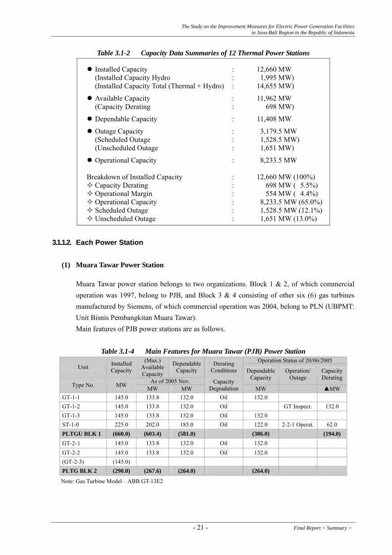
Table 3.1-2 shows the summarized capacity data of the objective twelve (12) thermal power stations on June 20, 2005 when the serous power supply shortage had occurred in Java-Bali region.
Final Report < Summary > - 20 -
The Study on the Improvement Measures for Electric Power Generation Facilities in Java-Bali Region in the Republic of Indonesia
Table 3.1-2 Capacity Data Summaries of 12 Thermal Power Stations
Installed Capacity : 12,660 MW (Installed Capacity Hydro : 1,995 MW) (Installed Capacity Total (Thermal + Hydro) : 14,655 MW)
Available Capacity : 11,962 MW (Capacity Derating : 698 MW)
Dependable Capacity : 11,408 MW
Outage Capacity : 3,179.5 MW (Scheduled Outage : 1,528.5 MW) (Unscheduled Outage : 1,651 MW)
Operational Capacity : 8,233.5 MW Breakdown of Installed Capacity : 12,660 MW (100%)
Capacity Derating : 698 MW ( 5.5%) Operational Margin : 554 MW ( 4.4%) Operational Capacity : 8,233.5 MW (65.0%) Scheduled Outage : 1,528.5 MW (12.1%) Unscheduled Outage : 1,651 MW (13.0%)
3.1.1.2. Each Power Station
(1) Muara Tawar Power Station
Muara Tawar power station belongs to two organizations. Block 1 & 2, of which commercial operation was 1997, belong to PJB, and Block 3 & 4 consisting of other six (6) gas turbines manufactured by Siemens, of which commercial operation was 2004, belong to PLN (UBPMT: Unit Bisnis Pembangkitan Muara Tawar). Main features of PJB power stations are as follows.
Table 3.1-4 Main Features for Muara Tawar (PJB) Power Station
Operation Status of 20/06/2005 Unit Installed
Capacity
(Max.) Available Capacity
Dependable Capacity
Derating Conditions
As of 2005 Nov.
Dependable Capacity
Operation/ Outage
Capacity Derating
Type No. MW MW MW Capacity
Degradation MW ▲MW
GT-1-1 145.0 133.8 132.0 Oil 132.0 GT-1-2 145.0 133.8 132.0 Oil GT Inspect. 132.0 GT-1-3 145.0 133.8 132.0 Oil 132.0 ST-1-0 225.0 202.0 185.0 Oil 122.0 2-2-1 Operat. 62.0 PLTGU BLK 1 (660.0) (603.4) (581.0) (386.0) (194.0) GT-2-1 145.0 133.8 132.0 Oil 132.0 GT-2-2 145.0 133.8 132.0 Oil 132.0 (GT-2-3) (145.0) PLTG BLK 2 (290.0) (267.6) (264.0) (264.0)
Note: Gas Turbine Model – ABB GT-13E2
- 21 - Final Report < Summary >
The Study on the Improvement Measures for Electric Power Generation Facilities in Java-Bali Region in the Republic of Indonesia
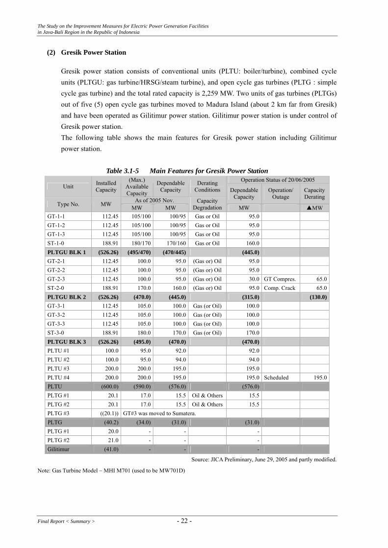
(2) Gresik Power Station
Gresik power station consists of conventional units (PLTU: boiler/turbine), combined cycle units (PLTGU: gas turbine/HRSG/steam turbine), and open cycle gas turbines (PLTG : simple cycle gas turbine) and the total rated capacity is 2,259 MW. Two units of gas turbines (PLTGs) out of five (5) open cycle gas turbines moved to Madura Island (about 2 km far from Gresik) and have been operated as Gilitimur power station. Gilitimur power station is under control of Gresik power station. The following table shows the main features for Gresik power station including Gilitimur power station.
Table 3.1-5 Main Features for Gresik Power Station
Operation Status of 20/06/2005 Unit Installed
Capacity
(Max.) Available Capacity
Dependable Capacity
Derating Conditions
As of 2005 Nov.
Dependable Capacity
Operation/ Outage
Capacity Derating
Type No. MW MW MW Capacity
Degradation MW ▲MW
GT-1-1 112.45 105/100 100/95 Gas or Oil 95.0 GT-1-2 112.45 105/100 100/95 Gas or Oil 95.0 GT-1-3 112.45 105/100 100/95 Gas or Oil 95.0 ST-1-0 188.91 180/170 170/160 Gas or Oil 160.0 PLTGU BLK 1 (526.26) (495/470) (470/445) (445.0) GT-2-1 112.45 100.0 95.0 (Gas or) Oil 95.0 GT-2-2 112.45 100.0 95.0 (Gas or) Oil 95.0 GT-2-3 112.45 100.0 95.0 (Gas or) Oil 30.0 GT Compres. 65.0 ST-2-0 188.91 170.0 160.0 (Gas or) Oil 95.0 Comp. Crack 65.0 PLTGU BLK 2 (526.26) (470.0) (445.0) (315.0) (130.0)GT-3-1 112.45 105.0 100.0 Gas (or Oil) 100.0 GT-3-2 112.45 105.0 100.0 Gas (or Oil) 100.0 GT-3-3 112.45 105.0 100.0 Gas (or Oil) 100.0 ST-3-0 188.91 180.0 170.0 Gas (or Oil) 170.0 PLTGU BLK 3 (526.26) (495.0) (470.0) (470.0) PLTU #1 100.0 95.0 92.0 92.0 PLTU #2 100.0 95.0 94.0 94.0 PLTU #3 200.0 200.0 195.0 195.0 PLTU #4 200.0 200.0 195.0 195.0 Scheduled 195.0 PLTU (600.0) (590.0) (576.0) (576.0) PLTG #1 20.1 17.0 15.5 Oil & Others 15.5 PLTG #2 20.1 17.0 15.5 Oil & Others 15.5 PLTG #3 ((20.1)) GT#3 was moved to Sumatera. PLTG (40.2) (34.0) (31.0) (31.0) PLTG #1 20.0 - - - PLTG #2 21.0 - - - Gilitimur (41.0) - - -
Source: JICA Preliminary, June 29, 2005 and partly modified.
Note: Gas Turbine Model – MHI M701 (used to be MW701D)
Final Report < Summary > - 22 -
The Study on the Improvement Measures for Electric Power Generation Facilities in Java-Bali Region in the Republic of Indonesia
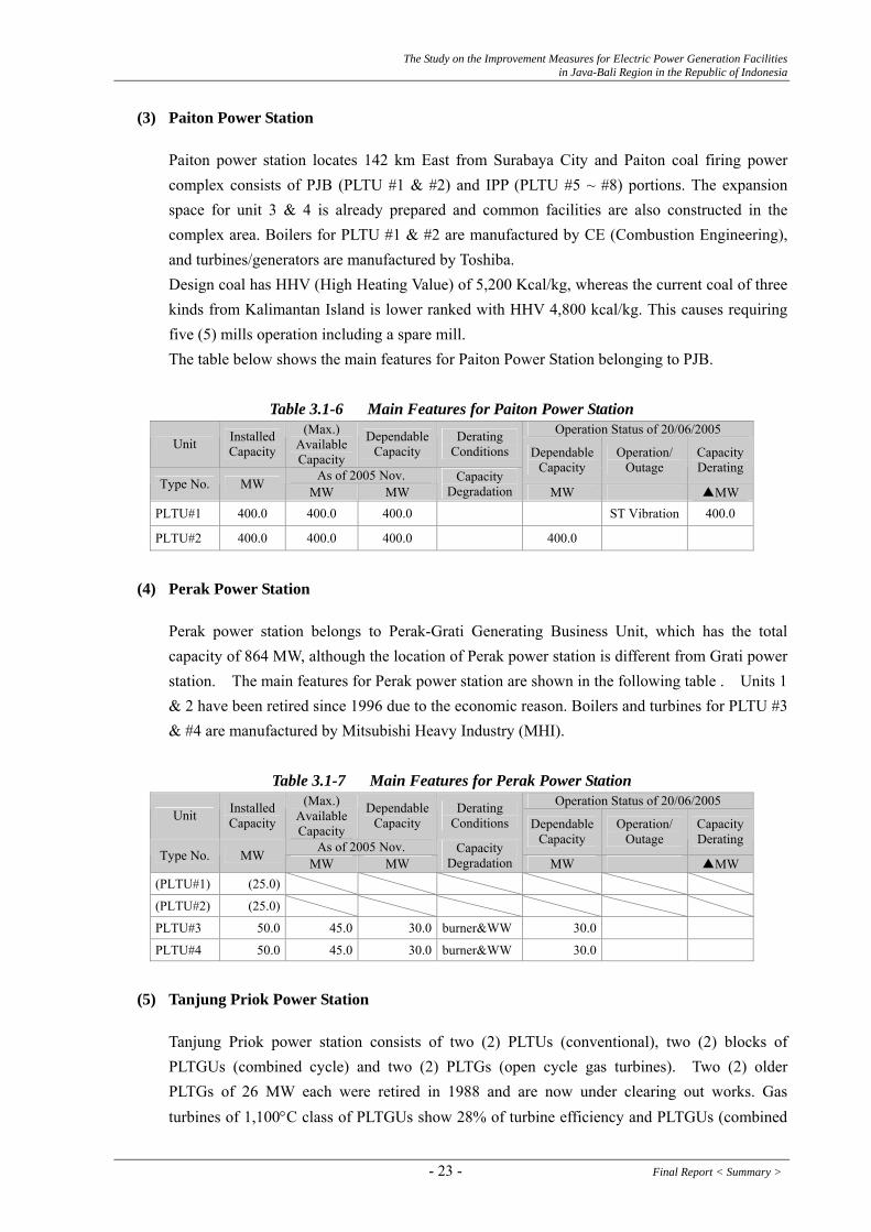
(3) Paiton Power Station
Paiton power station locates 142 km East from Surabaya City and Paiton coal firing power complex consists of PJB (PLTU #1 & #2) and IPP (PLTU #5 ~ #8) portions. The expansion space for unit 3 & 4 is already prepared and common facilities are also constructed in the complex area. Boilers for PLTU #1 & #2 are manufactured by CE (Combustion Engineering), and turbines/generators are manufactured by Toshiba. Design coal has HHV (High Heating Value) of 5,200 Kcal/kg, whereas the current coal of three kinds from Kalimantan Island is lower ranked with HHV 4,800 kcal/kg. This causes requiring five (5) mills operation including a spare mill. The table below shows the main features for Paiton Power Station belonging to PJB.
Table 3.1-6 Main Features for Paiton Power Station
Operation Status of 20/06/2005 Unit Installed
Capacity
(Max.) Available Capacity
Dependable Capacity
Derating Conditions
As of 2005 Nov.
Dependable Capacity
Operation/ Outage
Capacity Derating
Type No. MW MW MW Capacity
Degradation MW ▲MW
PLTU#1 400.0 400.0 400.0 ST Vibration 400.0
PLTU#2 400.0 400.0 400.0 400.0
(4) Perak Power Station
Perak power station belongs to Perak-Grati Generating Business Unit, which has the total capacity of 864 MW, although the location of Perak power station is different from Grati power station. The main features for Perak power station are shown in the following table . Units 1 & 2 have been retired since 1996 due to the economic reason. Boilers and turbines for PLTU #3 & #4 are manufactured by Mitsubishi Heavy Industry (MHI).
Table 3.1-7 Main Features for Perak Power Station Operation Status of 20/06/2005
Unit Installed Capacity
(Max.) Available Capacity
Dependable Capacity
Derating Conditions
As of 2005 Nov.
Dependable Capacity
Operation/ Outage
Capacity Derating
Type No. MW MW MW Capacity
Degradation MW ▲MW
(PLTU#1) (25.0)
(PLTU#2) (25.0)
PLTU#3 50.0 45.0 30.0 burner&WW 30.0
PLTU#4 50.0 45.0 30.0 burner&WW 30.0
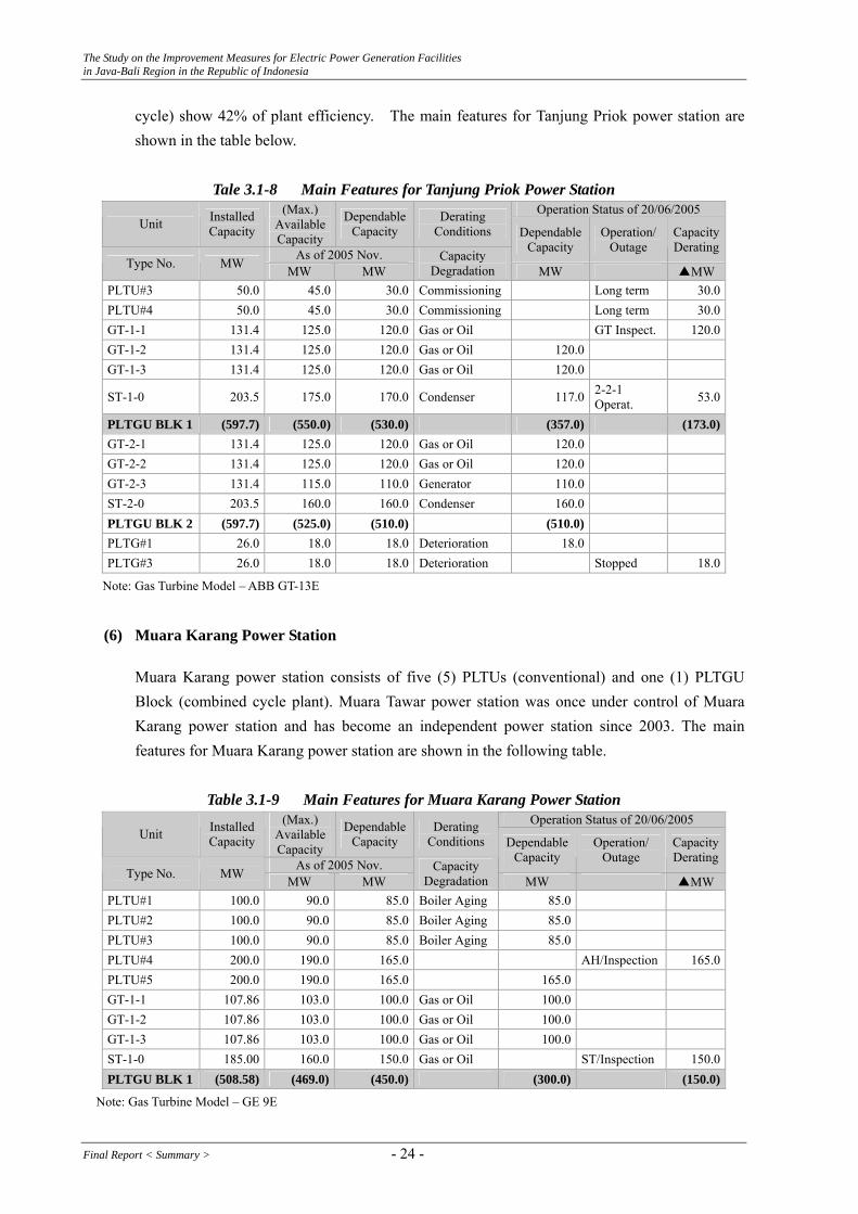
(5) Tanjung Priok Power Station
Tanjung Priok power station consists of two (2) PLTUs (conventional), two (2) blocks of PLTGUs (combined cycle) and two (2) PLTGs (open cycle gas turbines). Two (2) older PLTGs of 26 MW each were retired in 1988 and are now under clearing out works. Gas turbines of 1,100°C class of PLTGUs show 28% of turbine efficiency and PLTGUs (combined
- 23 - Final Report < Summary >
The Study on the Improvement Measures for Electric Power Generation Facilities in Java-Bali Region in the Republic of Indonesia
cycle) show 42% of plant efficiency. The main features for Tanjung Priok power station are shown in the table below.
Tale 3.1-8 Main Features for Tanjung Priok Power Station
Operation Status of 20/06/2005 Unit Installed
Capacity
(Max.) Available Capacity
Dependable Capacity
Derating Conditions
As of 2005 Nov.
Dependable Capacity
Operation/ Outage
Capacity Derating
Type No. MW MW MW Capacity
Degradation MW ▲MWPLTU#3 50.0 45.0 30.0 Commissioning Long term 30.0 PLTU#4 50.0 45.0 30.0 Commissioning Long term 30.0 GT-1-1 131.4 125.0 120.0 Gas or Oil GT Inspect. 120.0 GT-1-2 131.4 125.0 120.0 Gas or Oil 120.0 GT-1-3 131.4 125.0 120.0 Gas or Oil 120.0
ST-1-0 203.5 175.0 170.0 Condenser 117.0 2-2-1 Operat. 53.0
PLTGU BLK 1 (597.7) (550.0) (530.0) (357.0) (173.0)GT-2-1 131.4 125.0 120.0 Gas or Oil 120.0 GT-2-2 131.4 125.0 120.0 Gas or Oil 120.0 GT-2-3 131.4 115.0 110.0 Generator 110.0 ST-2-0 203.5 160.0 160.0 Condenser 160.0 PLTGU BLK 2 (597.7) (525.0) (510.0) (510.0) PLTG#1 26.0 18.0 18.0 Deterioration 18.0 PLTG#3 26.0 18.0 18.0 Deterioration Stopped 18.0
Note: Gas Turbine Model – ABB GT-13E
(6) Muara Karang Power Station
Muara Karang power station consists of five (5) PLTUs (conventional) and one (1) PLTGU Block (combined cycle plant). Muara Tawar power station was once under control of Muara Karang power station and has become an independent power station since 2003. The main features for Muara Karang power station are shown in the following table.
Table 3.1-9 Main Features for Muara Karang Power Station
Operation Status of 20/06/2005 Unit Installed
Capacity
(Max.) Available Capacity
Dependable Capacity
Derating Conditions
As of 2005 Nov.
Dependable Capacity
Operation/ Outage
Capacity Derating
Type No. MW MW MW Capacity
Degradation MW ▲MWPLTU#1 100.0 90.0 85.0 Boiler Aging 85.0 PLTU#2 100.0 90.0 85.0 Boiler Aging 85.0 PLTU#3 100.0 90.0 85.0 Boiler Aging 85.0 PLTU#4 200.0 190.0 165.0 AH/Inspection 165.0 PLTU#5 200.0 190.0 165.0 165.0 GT-1-1 107.86 103.0 100.0 Gas or Oil 100.0 GT-1-2 107.86 103.0 100.0 Gas or Oil 100.0 GT-1-3 107.86 103.0 100.0 Gas or Oil 100.0 ST-1-0 185.00 160.0 150.0 Gas or Oil ST/Inspection 150.0 PLTGU BLK 1 (508.58) (469.0) (450.0) (300.0) (150.0)
Note: Gas Turbine Model – GE 9E
Final Report < Summary > - 24 -

The Study on the Improvement Measures for Electric Power Generation Facilities in Java-Bali Region in the Republic of Indonesia
(7) Tambak Lorok Power Station
Tambak Lorok power station consists of three (3) PLTUs (conventional) and two (2) Blocks of PLTGUs (combined cycle plant) and belongs to UBP Semarang. The table below shows the main features for Tambak Lorok power station.
Table 3.1-10 Main Feature for Tambak Lorok Power Station
Operation Status of 20/06/2005 Unit Installed
Capacity
(Max.) Available Capacity
Dependable Capacity
Derating Conditions
As of 2005 Nov.
Dependable Capacity
Operation/ Outage
Capacity Derating
Type No. MW MW MW Capacity
Degradation MW ▲MW
PLTU#1 50.0 45.0 44.5 Burner 44.5 PLTU#2 50.0 45.0 44.5 Burner 44.5 PLTU#3 200.0 200.0 195.0 195.0 GT-1-1 109.65 105.0 100.0 Oil 100.0 GT-1-2 109.65 105.0 100.0 Oil 100.0 GT-1-3 109.65 105.0 100.0 Oil 100.0 ST-1-0 188.00 170.0 160.0 Oil 160.0 PLTGU BLK 1 (516.95) (485.0) (460.0) (460.0) GT-2-1 109.65 105.0 100.0 Oil GT Inspect. 100.0 GT-2-2 109.65 105.0 100.0 Oil 100.0 GT-2-3 109.65 105.0 100.0 Oil 100.0 ST-2-0 188.00 170.0 160.0 Oil 107.0 2-2-1 Operat. 53.0 PLTGU BLK 2 (516.95) (485.0) (460.0) (307.0) (153.0)
Note: Gas Turbine Model – GE 9E
(8) Grati Power Station
Grati power station consists of PLTGU combined cycle and PLTG open cycle gas turbine plants. Perak - Grati Generating Business Unit Office is in the site of Grati Power Station. The following table shows the main features for Grati power station.
Table 3.1-11 Main Features for Grati Power Station
Operation Status of 20/06/2005 Unit Installed
Capacity
(Max.) Available Capacity
Dependable Capacity
Derating Conditions
As of 2005 Nov.
Dependable Capacity
Operation/ Outage
Capacity Derating
Type No. MW MW MW Capacity
Degradation MW ▲MW
GT-1-1 112.45 100.75 100.0 Oil Fuel supply 100.0 GT-1-2 112.45 100.75 100.0 Oil Fuel supply 100.0 GT-1-3 112.45 100.75 100.0 Oil Fuel supply 100.0 ST-1-0 189.50 159.58 150.0 Oil Fuel supply 150.0 PLTGU BLK 1 (526.85) (461.83) (450.0) Fuel supply (450.0)GT-2-1 113.84 101.90 100.0 Oil Fuel supply 100.0 GT-2-2 113.84 101.90 100.0 Oil Fuel supply 100.0 GT-2-3 113.84 101.90 100.0 Oil Fuel supply 100.0 PLTG BLK 2 (341.52) (305.70) (300.0) Fuel supply (300.0)
Note: Gas Turbine Model – MHI M701 (used to be MW701D)
- 25 - Final Report < Summary >

The Study on the Improvement Measures for Electric Power Generation Facilities in Java-Bali Region in the Republic of Indonesia
(9) Suralaya Power Station
Suralaya power station consists of conventional (steam) power plant. The following table shows the main features for Suralaya power station.
Table 3.1-12 Main Features for Suralaya Power Station
Operation Status of 20/06/2005 Unit Installed
Capacity
(Max.) Available Capacity
Dependable Capacity
Derating Conditions
As of 2005 Nov.
Dependable Capacity
Operation/ Outage
Capacity Derating
Type No. MW MW MW Capacity
Degradation MW ▲MW
PLTU #1 400 400.0 371.0 Mill&Tube 371.0 (Scheduled)
PLTU#2 400 400.0 371.0 Mill&Tube Scheduled 371.0
PLTU#3 400 400.0 371.0 Mill&Tube 371.0
PLTU#4 400 400.0 371.0 Mill&Tube Forced 371.0
PLTU#1-#4Σ (1600) (1600.0) (1484.0) (742.0) (742.0)PLTU#5 600(630) 600.0 579.0 Mill 579.0 PLTU#6 600(630) 600.0 579.0 Mill 579.0 PLTU#7 600(630) 600.0 579.0 (Mill) 579.0 PLTU#5-#7Σ (1800) (1800.0) (1737.0) (1737.0)
(10) Pesanggaran Power Station
Pesanggaran power station consists of eleven (11) PLTD diesel generators and four (4) PLTG open cycle gas turbine plants. UBP Bali, Bali Generation Business Unit of Indonesian Power located in Pesanggaran power station manages and controls these Pesanggaran units and other power units in Gilimanuk and Pemaron power stations.
Table 3.1-13 Main Features for Pesanggaran Power Station
Operation Status of 20/06/2005 Unit Installed
Capacity
(Max.) Available Capacity
Dependable Capacity
Derating Conditions
As of 2005 Nov.
Dependable Capacity
Operation/ Outage
Capacity Derating
Type No. MW MW MW Capacity
Degradation MW ▲MW
PLTD#1~#11 Total 75.82 Total 60.91 Total 58.64 Total 54.14 TD#1Stopped 4.5 PLTG#1 21.4 19.5 Oil & Ambient PLTG#2 20.1 18.0 Oil & Ambient PLTG#3 42.0 37.1 Oil & Ambient PLTG#4 42.0 35.1
Total 109.7
Oil & Ambient
Total 109.7
Manufacturer for PLTD#1 to #7 : Mirrlees BS, Manufacturer for PLTD#8 to #11 : SWD GT#1 Model: Alstom PG.5341 P, GT#2 Model: GE MS.500, GT#3 Model: WH 251B11
(11) Gilimanuk Power Station
Gilimanuk power station has only one gas turbine plant, which was moved from Muara Tawar power station in 1997. Transmission line from Java Island is connecting to Bali grid system at 150 kV Gilimanuk switchyard by the submarine cable.
Final Report < Summary > - 26 -

The Study on the Improvement Measures for Electric Power Generation Facilities in Java-Bali Region in the Republic of Indonesia
The following table shows the main features for Gilimanuk power station.
Table 3.1-14 Main Features for Gilimanuk Power Station Operation Status of 20/06/2005
Unit Installed Capacity
(Max.) Available Capacity
Dependable Capacity
Derating Conditions
As of 2005 Nov.
Dependable Capacity
Operation/ Outage
Capacity Derating
Type No. MW MW MW Capacity
Degradation MW ▲MW
PLTG#1 133.8 133.8 132.0 132.0
GT Model; ABB GT-13E2
(12) Pemaron Power Station
Pemaron power station has two gas turbine generators, which were moved from Tanjung Priok power station in 2002. The unit 1 and the unit 2 have just started the commercial operation since November 2004 and October 2005, respectively. HRSG blocks, a completely assembled steam turbine and a assembled generator necessary for a bottoming cycle plant to be combined to these gas turbines had been purchased and are now being stored in the site. The table below shows the main features for Pemaron power station.
Table 3.1-15 Main Features for Pemaron Power Station
Operation Status of 20/06/2005 Unit Installed
Capacity
(Max.) Available Capacity
Dependable Capacity
Derating Conditions
As of 2005 Nov.
Dependable Capacity
Operation/ Outage
Capacity Derating
Type No. MW MW MW Capacity
Degradation MW ▲MW
PLTG#1 48.8 45.0 45.0 Oil & Others 45.0
PLTG#2 48.8 45.0 45.0 Oil & Others Installation 45.0 (ST-1-0) (48.4) (PLTGU BLK 1) ((146.0)) C/C conversion is postponed.
GT Model: GE MS.7001
3.1.1.3. Original Proposals of Rehabilitation, Modification and Repowering Plans
After the 1st Field Work, JICA Study Team proposed at the 1st Workshop, Table 3.1-16 (1) Original Proposals of Rehabilitation, Modification and Repowering Plans for IP units and Table 3.1-16 (2) -Ditto- for PJB below;
- 27 - Final Report < Summary >

The Study on the Improvement Measures for Electric Power Generation Facilities in Java-Bali Region in the Republic of Indonesia
Table 3.1-16 (1) Original Proposals of Rehabilitation, Modification and Repowering Plans for IP Power Station Proposed Plan MW Gain
Suralaya - -
PLTU#3 Modification Plan: Burner system modification & turbine uprating plan (PLTU#3) 30 MW
Perak PLTU#3 Repowering Plan: One block of C/C conversion of PLTU#3 STs
(1-1-2) 250 MW (GT)
Block-I & Block-II
Rehabilitation/Modification Plan: Block 1 & 2 condenser and cooling system modification plan 30 MW Tanjung
Priok PLTU#3 Repowering Plan: One block of C/C conversion of PLTU#3 STs
(1-1-2) 250 MW (GT)
PLTU#1
Rehabilitation/Uprating Plan: Boilers/Turbines/Generators refurbishment plan of PLTU#1 20 MW Tambak
Lorok PLTU#1 Repowering Plan: One block of C/C conversion of PLTU#1 (1-1-2) 250 MW (GT)
Grati PLTG B-II Repowering Plan: One block of C/C conversion of PLTG B-II GTs (3-3-1) 160 MW (ST)
Pesanggaran PLTU#3 Repowering Plan: One block of C/C conversion of PLTU#3 (2-2-1) 40 MW (ST)
Gilimanuk PLTG Repowering Plan: One block of C/C conversion of PLTG gas turbine (1-1-1) 65 MW (ST)
Table 3.1-16 (2) Original Proposals of Rehabilitation, Modification and Repowering Plans for PJB
Power Station Proposed Plan MW Gain
Gresik Repowering Plan: Two (2) blocks of C/C conversion of PLTU#1 STs (1-1-1 × 2) 500MW
Paiton Modification Plan: Final RH four (4) panels replacement (T11/12⇒T91) Equivalent. 75MW
Muara Tawar Repowering Plan: One block of C/C conversion of PLTG Block 2 GTs (3-3-1) 295MW
Muara Karang - -
3.1.1.4. Additional Proposals of Oil Reduction Plans
After further study of the operation and performance data of objective twelve (12) thermal stations as overviewed thoroughly in the Section 3.1.1.1 of this chapter, additional themes to combine with the Study: “Oil Reduction” was clearly closed up. • Oil consumption reduction plan with repowering concept, sometimes even no repowering to
be required. • Totally real oil reduction scheme per UBP, this means stopping less efficient oil fired units
and conversion to higher efficient C/C plant of another less efficient oil fired units • Oil reduction means less oil consumption and less CO2 emission. After over viewing the objective twelve (12) thermal power stations per UBP again, three (3) oil reduction plans are thought out as listed in the Table 3.1-17 below by combining with repowering concepts.
Final Report < Summary > - 28 -

The Study on the Improvement Measures for Electric Power Generation Facilities in Java-Bali Region in the Republic of Indonesia
Table 3.1-17 Additional Proposals of Oil Reduction Plans Power Station Proposed Plan MW Gain
UBP Semarang T.Lorok, Sunyaragi, Cilacap
One block of combined cycle conversion plan (PLTGU 1-1-2) consisting of a newly installed large GT instead of the existing Sunyaragi PLTG #1 to #4 and Cilacap PLTG #1, a HRSG and the existing PLTU#1 two (2) steam turbines.
100MW (238-(80+58))
UBP Perak Grati Perak Grati
One block of combined cycle conversion project (PLTGU 3-3-1) combining the existing PLTG Block 2 three (3) gas turbines, newly installed three (3) HRSGs and one (1) steam turbine instead of the existing Perak PLTU #3 STs.
60MW (160-100)
UBP Bali Gilimanuk, Pesanggaran
One block of combined cycle conversion project (PLTGU 1-1-1) combining the existing Gilimanuk gas turbine, a newly installed HRSG and a newly installed steam turbine instead of the existing Pesanggaran PLTG #1 GTs.
24MW (65-20-21)
3.1.2. Hydropower Stations
The main features of the objective power stations are shown in the Table 3.1-19.
Table 3.1-19 Main Features of Objective Hydropower Stations
Saguling Cirata Soedirman Sutami Company name IP PJB IP PJB River name Citarum Citarum Serayu Brantas Plant output 700.72 MW 1,008 MW 180.9 MW 105 MW Turbine rated value
Type Vertical Francis Vertical Francis Vertical Francis Vertical Francis Output 178.8 MW 129.6 MW 61.5 MW 36 MW Net head 355.7 m 106.8 m 88.5 m 78.0m Discharge 56 m3/s 132.5 m3/s 74 m3/s 53.5 m3/s Speed 333.3 r/m 187.5 r/m 230.8 r/m 250 r/m Number of unit 4 8 3 3 Manufacturer TOSHIBA VOEST ALPINE BOVING TOSHIBA
Generator rated value Output 206.1MVA 140MVA 67.01MVA 39MVA Power factor 0.85 0.9 0.9 0.9 Voltage 16.5kV 16.5kV 13.8kV 11kV Frequency 50Hz 50Hz 50Hz 50Hz Number of unit 4 8 3 3 Manufacturer MITSUBISHI ELIN ASEA TOSHIBA
Main transformer rated value Output 412.2 MVA
(for 2units) 280 MVA
(for 2units) 70 MVA 39 MVA
Voltage 16.5/525kV 16.5/525kV 13.8/154kV 11/154kV Number of unit 2 4Bank (1φ×3) 3 3 Manufacturer MITSUBISHI ALSTOM ASEA TOSHIBA Commencement date of commercial operation
#1;12/Oct/1985 #2;28/Nov/1985 #3;3/Apr/1986
#4;29/May/1986
#1;25/May/1988 #2;29/Feb/1988 #3;30/Sep/1988 #4;10/Aug/1988 #5;15/Aug/1997 #6;15/Aug/1997 #7;15/Apr/1998 #8;15/Apr/1998
Nov./1988
#1; Sep/1973 #2; Feb/1976 #3; Feb/1976
Purpose Power Power Power Irrigation, Power, Water Supply, Flood Control
Reservoir Catchment Area 2,283 km2 4,119 km2 1,022 km2 2,052 km2
HWL 643.00 220.00 231.00 272.5 LWL 623.00 205.00 224.50 246.0 Gross volume 881 Million m3 1,920 Million m3 165 Million m3 343 Million m3
Effective Volume 609 Million m3 796 Million m3 47 Million m3 253 Million m3
Source; PJB & INDONESIA POWER data
- 29 - Final Report < Summary >
The Study on the Improvement Measures for Electric Power Generation Facilities in Java-Bali Region in the Republic of Indonesia
(1) Saguling
Any derating of power output for every unit is not reported at the moment. For unit No.3, minimum output is restricted to 100 MW due to the reason that the thrust bearing temperature has risen abnormally during the operation at less than 100 MW since the last 3 years.
(2) Cirata
Any derating for every unit is not reported at the moment. Due to the deterioration of the reservoir water quality, closed circuit cooling water system is planned to prevent the relevant troubles in the cooling system (water leakage, corrosion in the piping).Cirata has the LFC (load frequency control) function to adjust the frequency of the Java Bali Power Grid System.
(3) Soedirman
Any derating for every unit is not reported at the moment. Whole unit is operated normally at present. Therefore overhaul of the main machines has not been carried out.
(4) Sutami
Any derating for every unit is not reported at the present. Whole unit is operated normally at present without serious trouble.
3.2. Confirmation of Current Status and Issues Relating to Operation and Maintenance 3.2.1. Thermal Power Stations
Figure 3.2-2 shows the annual operation records of Year 2004 seen from the viewpoint of operation hours of the thermal power stations under the study.
Final Report < Summary > - 30 -
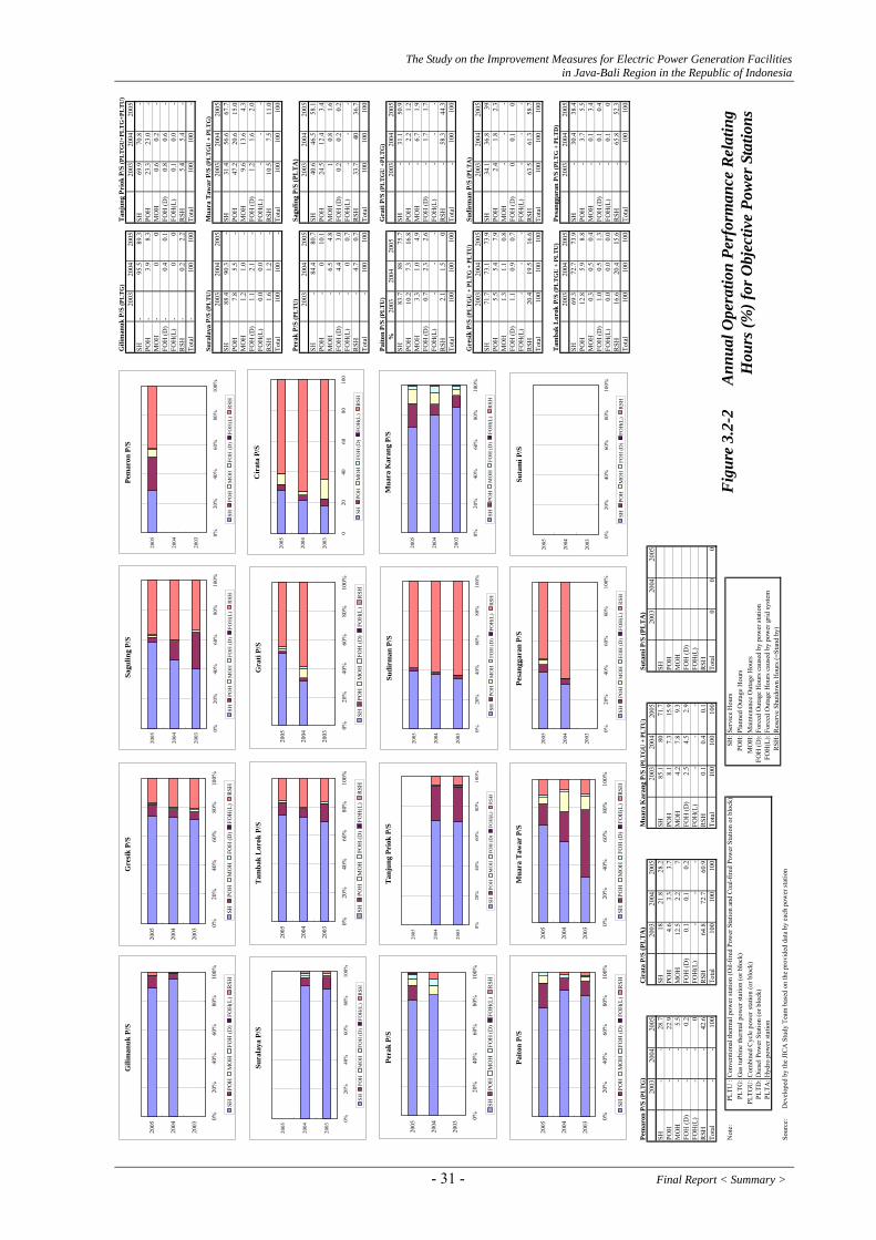
The Study on the Improvement Measures for Electric Power Generation Facilities in Java-Bali Region in the Republic of Indonesia
Gili
man
uk P
/S (P
LT
G)
Tan
jung
Pri
ok P
/S (P
LT
GU
+PL
TG
+PL
TU
)20
0320
0420
0520
0320
0420
05SH
-95
.589
.3SH
69.9
70.8
-PO
H-
3.9
8.3
POH
23.3
23.0
-M
OH
-0
0M
OH
0.6
0.2
-FO
H (D
)-
0.4
0.1
FOH
(D)
0.8
0.6
-FO
H(L
)-
00
FOH
(L)
0.1
0.0
-R
SH-
0.2
2.2
RSH
5.4
5.4
-To
tal
-10
010
0To
tal
100
100
-
Sura
laya
P/S
(PL
TU
)M
uara
Taw
ar P
/S (P
LT
GU
+ P
LT
G)
2003
2004
2005
2003
2004
2005
SH88
.490
.3-
SH31
.456
.667
.7PO
H7.
85.
5-
POH
47.2
20.6
15.0
MO
H1.
21.
0-
MO
H9.
613
.64.
3FO
H (D
)1.
12.
1-
FOH
(D)
1.2
1.6
2.0
FOH
(L)
0.0
0.0
-FO
H(L
)-
--
RSH
1.6
1.2
-R
SH10
.57.
511
.0To
tal
100
100
-To
tal
100
100
100
Pera
k P/
S (P
LT
U)
Sagu
ling
P/S
(PL
TA
)20
0320
0420
0520
0320
0420
05SH
-84
.480
.7SH
40.6
46.5
58.1
POH
-0
10.1
POH
24.5
12.4
3.4
MO
H-
6.5
4.8
MO
H1
0.8
1.6
FOH
(D)
-4.
43.
0FO
H (D
)0.
20.
20.
2FO
H(L
)-
00.
7FO
H(L
)-
--
RSH
-4.
70.
7R
SH33
.740
36.7
Tota
l-
100
100
Tota
l10
010
010
0
Paito
n P/
S (P
LT
U)
Gra
ti P/
S (P
LT
GU
+PL
TG
)%
2003
2004
2005
2003
2004
2005
SH83
.788
75.7
SH-
31.1
50.9
POH
10.2
7.3
16.8
POH
-2.
21.
2M
OH
3.3
1.0
4.9
MO
H-
6.7
1.9
FOH
(D)
0.7
2.3
2.6
FOH
(D)
-1.
71.
7FO
H(L
)-
--
FOH
(L)
--
-R
SH2.
11.
50
RSH
-58
.344
.3To
tal
100
100
100
Tota
l-
100
100
Gre
sik
P/S
(PL
TG
U +
PL
TG
+ P
LT
U)
Sudi
rman
P/S
(PL
TA
)20
0320
0420
0520
0320
0420
05SH
71.7
73.1
73.9
SH34
.136
.839
POH
5.5
5.4
7.9
POH
2.4
1.8
2.3
MO
H1.
31.
10.
8M
OH
--
-FO
H (D
)1.
10.
90.
7FO
H (D
)0
0.1
0FO
H(L
)-
--
FOH
(L)
--
-R
SH20
.419
.516
.6R
SH63
.561
.358
.7To
tal
100
100
100
Tota
l10
010
010
0
Tam
bak
Lor
ok P
/S (P
LT
GU
+ P
LT
U)
Pesa
ngga
ran
P/S
(PL
TG
+ P
LT
D)
2003
2004
2005
2003
2004
2005
SH69
.372
.773
.9SH
-30
.438
.4PO
H12
.85.
98.
8PO
H-
3.7
5.5
MO
H0.
30.
50.
4M
OH
-0.
13.
4FO
H (D
)1.
00.
51.
3FO
H (D
)-
0.1
0.4
FOH
(L)
0.0
0.0
0.0
FOH
(L)
-0.
10
RSH
16.6
20.4
15.6
RSH
-65
.852
.3To
tal
100
100
100
Tota
l-
100
100
Pem
aron
P/S
(PL
TG
)C
irat
a P/
S (P
LT
A)
Mua
ra K
aran
g P/
S (P
LT
GU
+ P
LT
U)
Suta
mi P
/S (P
LT
A)
2003
2004
2005
2003
2004
2005
2003
2004
2005
2003
2004
2005
SH-
-28
.7SH
1821
.828
.2SH
85.1
8071
.7SH
POH
--
22.9
POH
4.6
3.3
3.7
POH
8.1
7.3
15.9
POH
MO
H-
-5.
5M
OH
12.5
2.2
7M
OH
4.2
7.8
9.3
MO
HFO
H (D
)-
-0.
2FO
H (D
)0.
10.
10.
2FO
H (D
)2.
54.
52.
9FO
H (D
)FO
H(L
)-
-0
FOH
(L)
--
-FO
H(L
)-
--
FOH
(L)
RSH
--
42.6
RSH
64.8
72.7
60.9
RSH
0.1
0.4
0.1
RSH
Tota
l-
-10
0To
tal
100
100
100
Tota
l10
010
010
0To
tal
00
0
Not
e:PL
TU :
Con
vent
iona
l the
rmal
pow
er st
atio
n (O
il-fir
ed P
ower
Sta
tion
and
Coa
l-fire
d Po
wer
Sta
tion
or b
lock
)SH
:Ser
vice
Hou
rsPL
TG:G
as tu
rbin
e th
erm
al p
ower
stat
ion
(or b
lock
)PO
H:P
lann
ed O
utag
e H
ours
PLTG
U:C
ombi
ned
Cyc
le p
ower
stat
ion
(or b
lock
) M
OH
:Mai
nten
ance
Out
age
Hou
rsPL
TD:D
iese
l Pow
er S
tatio
n (o
r blo
ck)
FOH
(D):
Forc
ed O
utag
e H
ours
cau
sed
by p
ower
stat
ion
PLTA
:Hyd
ro p
ower
stat
ion
FOH
(L):
Forc
ed O
utag
e H
ours
cau
sed
by p
ower
grid
syst
emR
SH:R
eser
ve S
hutd
own
Hou
rs (=
Stan
d by
)So
urce
:D
evel
oped
by
the
JIC
A S
tudy
Tea
m b
ased
on
the
prov
ided
dat
a by
eac
h po
wer
stat
ion
Paito
n P/
S
0%20
%40
%60
%80
%10
0%
2003
2004
2005
SHPO
HM
OH
FOH
(D)
FOH
(L)
RSH
Gre
sik
P/S
0%20
%40
%60
%80
%10
0%
2003
2004
2005
SHPO
HM
OH
FOH
(D)
FOH
(L)
RSH
Gra
ti P/
S
0%20
%40
%60
%80
%10
0%
2003
2004
2005
SHPO
HM
OH
FOH
(D)
FOH
(L)
RSH
Pera
k P/
S
0%20
%40
%60
%80
%10
0%
2003
2004
2005
SHPO
HM
OH
FOH
(D)
FOH
(L)
RSH
Mua
ra T
awar
P/S
0%20
%40
%60
%80
%10
0%
2003
2004
2005
SHPO
HM
OH
FOH
(D)
FOH
(L)
RSH
Tam
bak
Lor
ok P
/S
0%20
%40
%60
%80
%10
0%
2003
2004
2005
SHPO
HM
OH
FOH
(D)
FOH
(L)
RSH
Tan
jung
Pri
ok P
/S
0%20
%40
%60
%80
%10
0%
2003
2004
2005
SHPO
HM
OH
FOH
(D)
FOH
(L)
RSH
Sura
laya
P/S
0%20
%40
%60
%80
%10
0%
2003
2004
2005
SHPO
HM
OH
FOH
(D)
FOH
(L)
RSH
Mua
ra K
aran
g P/
S
0%20
%40
%60
%80
%10
0%
2003
2004
2005
SHPO
HM
OH
FOH
(D)
FOH
(L)
RSH
Pesa
ngga
ran
P/S
0%20
%40
%60
%80
%10
0%
2003
2004
2005
SHPO
HM
OH
FOH
(D)
FOH
(L)
RSH
Gili
man
uk P
/S
0%20
%40
%60
%80
%10
0%
2003
2004
2005
SHPO
HM
OH
FOH
(D)
FOH
(L)
RSH
Pem
aron
P/S
0%20
%40
%60
%80
%10
0%
2003
2004
2005
SHPO
HM
OH
FOH
(D)
FOH
(L)
RSH
Sudi
rman
P/S
0%20
%40
%60
%80
%10
0%
2003
2004
2005
SHPO
HM
OH
FOH
(D)
FOH
(L)
RSH
Sagu
ling
P/S
0%20
%40
%60
%80
%10
0%
2003
2004
2005
SHPO
HM
OH
FOH
(D)
FOH
(L)
RSH
Cir
ata
P/S
020
4060
8010
0
2003
2004
2005
SHPO
HM
OH
FOH
(D)
FOH
(L)
RSH
Suta
mi P
/S
0%20
%40
%60
%80
%10
0%
2003
2004
2005
RSH
FOH
(L)
FOH
(D)
MO
HPO
HSH
Fig
ure
3.2-
2
Ann
ual O
pera
tion
Perf
orm
ance
Rel
atin
g H
ours
(%) f
or O
bjec
tive
Pow
er S
tatio
ns
- 31 - Final Report < Summary >

The Study on the Improvement Measures for Electric Power Generation Facilities in Java-Bali Region in the Republic of Indonesia
The number and hours of forced outages are analised including the causes as mentioned later for 75 units (PLTU: 23, PLTG: 12, PLTGU: 40) among the objective thermal power stations.
(1) Number of outages and hours by unit type
The numbers of outages and hours during the three years from 2003 to 2005 are as shown below3.
105
150134
49 49
90
280
339
423434
538
647
0
100
200
300
400
500
600
700
1 2 3
PLTU PLTG PLTGU TotalSources : INDONESIA POWER & PJB data
Numbers of Forced Outages are too many and have been increasing in the past 3 years.
Type 2003 2004 2005 Total
PLTU 105 150 134 389 PLTG 49 49 90 188
PLTGU 280 339 423 1,042Total 434 538 647 1,619
Table 3.2-1 Forced Outage (Times) for Thermal Power Stations
Table 3.2-2 Forced Outage (Hours) for Thermal Power Stations
2,600
5,158
9,318
6781,239 1,010
10,168
8,426 8,115
13,446
14,823
18,443
-
2,000
4,000
6,000
8,000
10,000
12,000
14,000
16,000
18,000
20,000
2003 2004 2005
PLTU PLTG PLTGU Total
Type 2003 2004 2005 Total PLTU 2,600 5,158 9,318 17,076PLTG 678 1,239 1,010 2,927PLTGU 10,168 8,426 8,115 26,709Total 13,446 14,823 18,443 46,712
Forced Outage Hours are also too many and have been increasing in the past 3 years.
Sources : INDONESIA POWER & PJB data
3 The electricity-related accidents for hydropower stations and thermal power stations for 2004 in Japan are 115 and 72 respectively for your
reference (Source: nuclear and Industrial Safety Agency, METI).
Final Report < Summary > - 32 -
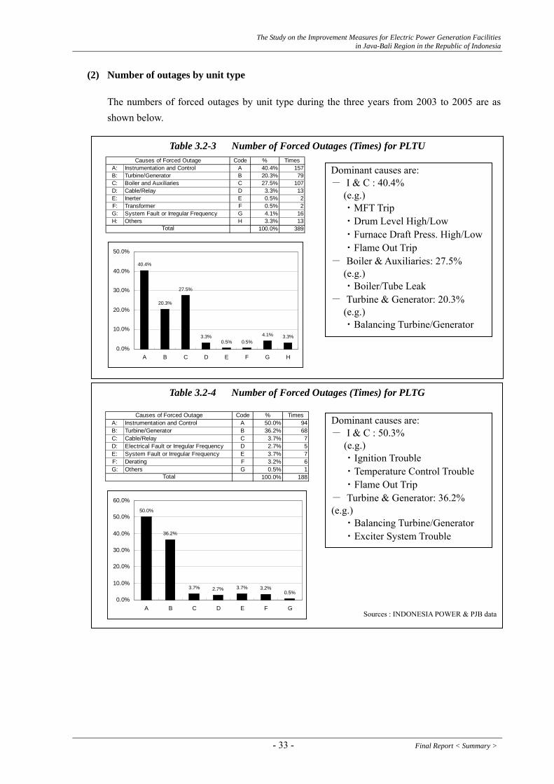
The Study on the Improvement Measures for Electric Power Generation Facilities in Java-Bali Region in the Republic of Indonesia
(2) Number of outages by unit type
The numbers of forced outages by unit type during the three years from 2003 to 2005 are as shown below.
Table 3.2-4 Number of Forced Outages (Times) for PLTG
Sources : INDONESIA POWER & PJB data
Causes of Forced Outage Code % Times
A: Instrumentation and Control A 40.4% 157B: Turbine/Generator B 20.3% 79C: Boiler and Auxiliaries C 27.5% 107D: Cable/Relay D 3.3% 13E: Inerter E 0.5% 2F: Transformer F 0.5% 2G: System Fault or Irregular Frequency G 4.1% 16H: Others H 3.3% 13
100.0% 389Total
40.4%
20.3%
27.5%
3.3%0.5% 0.5%
4.1% 3.3%
0.0%
10.0%
20.0%
30.0%
40.0%
50.0%
A B C D E F G H
Causes of Forced Outage Code % Times
A: Instrumentation and Control A 50.0% 94B: Turbine/Generator B 36.2% 68C: Cable/Relay C 3.7% 7D: Electrical Fault or Irregular Frequency D 2.7% 5E: System Fault or Irregular Frequency E 3.7% 7F: Derating F 3.2% 6G: Others G 0.5% 1
100.0%
Total 188
50.0%
36.2%
3.7% 2.7% 3.7% 3.2%0.5%
0.0%
10.0%
20.0%
30.0%
40.0%
50.0%
60.0%
A B C D E F G
Dominant causes are: - I & C : 50.3% (e.g.) ・Ignition Trouble ・Temperature Control Trouble ・Flame Out Trip - Turbine & Generator: 36.2% (e.g.) ・Balancing Turbine/Generator ・Exciter System Trouble
Dominant causes are: - I & C : 40.4% (e.g.) ・MFT Trip ・Drum Level High/Low ・Furnace Draft Press. High/Low ・Flame Out Trip - Boiler & Auxiliaries: 27.5% (e.g.) ・Boiler/Tube Leak - Turbine & Generator: 20.3% (e.g.) ・Balancing Turbine/Generator
Table 3.2-3 Number of Forced Outages (Times) for PLTU
- 33 - Final Report < Summary >

The Study on the Improvement Measures for Electric Power Generation Facilities in Java-Bali Region in the Republic of Indonesia
Table 3.2-5 Number of Forced Outages (Times) for PLTGU
Sources : INDONESIA POWER & PJB data
Dominant causes are: - I & C : 36.8% (e.g.) ・Exhaust Temperature High ・Flame Out Trip ・Ignition Trouble - Turbine & Generator: 17.9% ・Condenser Plugging ・Starting Motor Trouble - HRSG & Auxiliaries: 10.4% (e.g.) ・Exhaust Dumper Trouble
(3) Sharing of roles between Power Station and Maintenance Business Unit (UBHAR/UHAR) for Scheduled Maintenance
As shown in Table 3.2-9 and Table 3.2-10, there are differences between Indonesia Power and PJB in the details of assistance provided by the Maintenance Business Unit (UBHAR/UHAR) in Scheduled Inspection Work and Scheduled Special Order Maintenance Work.
Causes of Forced Outage Code % TimesA: Instrumentation and Control A 36.8% 383B: Turbine/Generator B 17.9% 186C: HRSG and Auxiliaries C 10.4% 108D: Relay D 1.2% 12E: 6kV Bus E 0.8% 8F: UPS System F 0.3% 3G: Electrical G 1.1% 11H: System Fault or Irregular Frequency H 7.4% 77I: Derating I 14.6% 152J: Others J 9.7% 101
100.0% 1041Total
36.8%
17.9%
10.4%
1.2% 0.8% 0.3% 1.1%
7.4%
14.6%
9.7%
0.0%
10.0%
20.0%
30.0%
40.0%
50.0%
A B C D E F G H I J
Indonesia Power’s UBHAR/UHAR : Main facilities such as boilers, turbines, generators, etc. PJB’s UBHAR/UHAR : All facilities such as main turbines, auxiliary machinery
and commonly used facilities.
Final Report < Summary > - 34 -
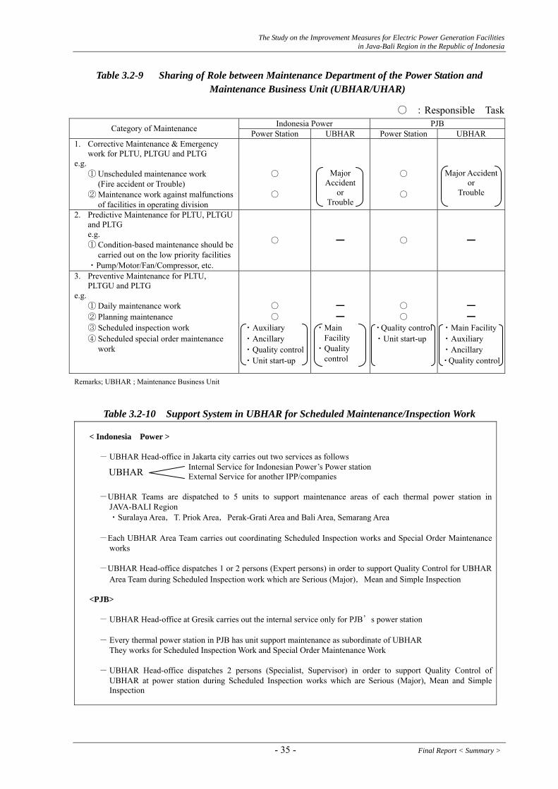
The Study on the Improvement Measures for Electric Power Generation Facilities in Java-Bali Region in the Republic of Indonesia
Table 3.2-9 Sharing of Role between Maintenance Department of the Power Station and Maintenance Business Unit (UBHAR/UHAR)
○ :Responsible Task Indonesia Power PJB Category of Maintenance Power Station UBHAR Power Station UBHAR
1. Corrective Maintenance & Emergency work for PLTU, PLTGU and PLTG
e.g. ① Unscheduled maintenance work
(Fire accident or Trouble)
○
② Maintenance work against malfunctions of facilities in operating division
○
Major Accident
or Trouble
○ ○
Major Accidentor
Trouble
2. Predictive Maintenance for PLTU, PLTGU and PLTG
e.g. ① Condition-based maintenance should be
carried out on the low priority facilities・Pump/Motor/Fan/Compressor, etc.
○ ━ ○ ━
3. Preventive Maintenance for PLTU, PLTGU and PLTG
e.g. ① Daily maintenance work ② Planning maintenance ③ Scheduled inspection work ④ Scheduled special order maintenance
work
○ ○
・Auxiliary ・Ancillary ・Quality control・Unit start-up
━ ━
・Main Facility ・Quality
control
○ ○
・Quality control ・Unit start-up
━ ━
・Main Facility・Auxiliary ・Ancillary ・Quality control
Remarks; UBHAR ; Maintenance Business Unit
Table 3.2-10 Support System in UBHAR for Scheduled Maintenance/Inspection Work
< Indonesia Power >
- UBHAR Head-office in Jakarta city carries out two services as follows Internal Service for Indonesian Power’s Power station External Service for another IPP/companies -UBHAR Teams are dispatched to 5 units to support maintenance areas of each thermal power station in
JAVA-BALI Region ・Suralaya Area,T. Priok Area,Perak-Grati Area and Bali Area, Semarang Area -Each UBHAR Area Team carries out coordinating Scheduled Inspection works and Special Order Maintenance
works -UBHAR Head-office dispatches 1 or 2 persons (Expert persons) in order to support Quality Control for UBHAR
Area Team during Scheduled Inspection work which are Serious (Major),Mean and Simple Inspection
<PJB> - UBHAR Head-office at Gresik carries out the internal service only for PJB’s power station - Every thermal power station in PJB has unit support maintenance as subordinate of UBHAR
They works for Scheduled Inspection Work and Special Order Maintenance Work - UBHAR Head-office dispatches 2 persons (Specialist, Supervisor) in order to support Quality Control of
UBHAR at power station during Scheduled Inspection works which are Serious (Major), Mean and Simple Inspection
UBHAR
- 35 - Final Report < Summary >

The Study on the Improvement Measures for Electric Power Generation Facilities in Java-Bali Region in the Republic of Indonesia
3.2.2. Hydropower Stations
Annual generation energy for each objective power station is shown in the following table.
Annual Generation Energy (MWh) Year Saguling Cirata Soedirman Sutami
1995 2,254.9 1,406.3 598.2 1996 2,504.0 1,472.6 524.3 1997 1,325.9 851.8 283.2 1998 3,131.8 1,734.2 629.4 1999 2,319.1 1,358.6 616.7 2000 2,272.5 1,285.4 569.1 2001 2,959.3 1,694.3 617.7 509.8 2002 2,313.3 1,368.7 361.8 490.1 2003 1,780.2 952.0 420.2 400.5 2004 1,990.5 1,132.9 437.8 451.1 2005 2,123.7 1,265.6 368.3 342.6
Note; Annual generation energy for the year 2005 is up to October. Source; PJB & INDONESIA POWER data
(1) Annual Start & Stop Frequency
1) Saguling
Number of annual start and stop frequencies for each unit are shown in the following table.
Annual Start and Stop Frequency Year Unit 1 Unit 2 Unit 3 Unit 4 2000 205 198 188 158 2001 199 163 178 183 2002 74 151 227 163 2003 101 159 260 246 2004 245 229 240 152 2005 158 174 245 177
Note; Annual start & stop for the year 2005 are up to October. Source; INDONESIA POWER data
2) Cirata
Number of annual start and stop frequencies for each unit are shown in the following table.
Annual Start and Stop Frequency Year Unit 1 Unit 2 Unit 3 Unit 4 Unit 5 Unit 6 Unit 7 Unit 8 2000 130 337 247 307 351 320 340 347 2001 122 222 49 297 312 339 331 325 2002 288 218 153 282 333 333 330 298 2003 280 302 0 253 292 286 320 291 2004 265 272 229 242 306 274 258 240 2005 238 239 222 211 238 218 223 110
Till end of Oct. in 2005 Source; PJB data
Final Report < Summary > - 36 -

The Study on the Improvement Measures for Electric Power Generation Facilities in Java-Bali Region in the Republic of Indonesia
3) Soedirman
Number of annual start and stop frequencies for each unit are shown in the following table.
Annual Start & Stop Frequency Year Unit 1 Unit 2 Unit 3 2000 2001 273 255 265 2002 276 278 272 2003 252 236 211 2004 263 283 261 2005 298 306 318
For the year 2005 is up to October Source; INDONESIA POWER data
4) Sutami
Number of annual start and stop frequencies for each unit are shown in the following table.
Annual Start & Stop Frequency Year Unit 1 Unit 2 Unit 3 2000 2001 132 146 246 2002 125 109 236 2003 211 113 277 2004 133 118 263 2005 129 128 266
For the year 2005 is up to October Source; PJB POWER data
(2) Typical Daily Operation Pattern
1) Saguling
Units operation is usually corresponding to peak load and units start/stop operation is requested by P3B Gandul Dispatching Center.
Also units output is controlled manually according to LFC (Load Frequency Control) system signal (This system is probably not a full automatic load frequency control.)
Source ; INDONESIA POWER data (2005.8.15)
Saguling Daily Operation Pattern (Load Curve)
0
100
200
300
400
500
600
0 6 12 18 24Time
Out
put(M
W)
Unit1 Unit2Unit3 Unit4Total
- 37 - Final Report < Summary >

The Study on the Improvement Measures for Electric Power Generation Facilities in Java-Bali Region in the Republic of Indonesia
2) Cirata
Units operation is usually corresponding to peak load and units start/stop operation is requested by P3B Gandul Dispatching Center.
Also units output is controlled manually according to LFC (Load Frequency Control) system signal (This system is probably not a full automatic load frequency control.)
Source; PJB data (2005.09.15)Cirata Daily Operation Pattern (Load Curve)
0
100
200
300
400
500
600
700
0 6 12 18 24
Time
OU
tput
(MW
)
Unit1 Unit2 Unit3
Unit4 Unit5 Unit6
Unit7 Unit8 Total
LFC condition is the same as Saguling.
3) Soedirman
Units operation is usually corresponding to peak load.
0
20
40
60
80
100
120
140
160
180
200
0 6 12 18 24Time
Out
put(M
W)
Unit1 Unit2Unit3 total
Source; INDONESIA POWER data (2005.1.15)
Soedirman Daily Operation Pattern (Load Curve) 4) Sutami
Units operation is basically corresponding to peak load, although one (1) unit is operated for a whole day. During the rainy season, sometimes full load operation is carried out for all day long.
0
10
20
30
40
50
60
70
80
0 6 12 18 24Time
OU
tput
(MW
)
unit1 unit2unit3 total
Source; PJB data (2005.8.28)
Sutami Daily Operation Pattern (Load Curve)
Final Report < Summary > - 38 -

The Study on the Improvement Measures for Electric Power Generation Facilities in Java-Bali Region in the Republic of Indonesia
(3) Routine Management (check items, frequency, etc.)
For all power stations, all areas in the powerhouse and switchyard are kept very clean and good arrangement. Any harmful rust and/or peeling of paint on all equipment were not observed. Emergency exit indications are installed at all stairs for safety.
Generally, the number of labels indicating the equipment/machine name, abbreviation number for whole equipment seems to be insufficient. Valve No. and valve open/close indicating tags are not found out for every power station.
Indication of normal range for the various meters such as pressure gauges, oil level gauges, and temperature meters seems to be insufficient.
(4) Organization of Operation and Maintenance Management
The organization of operation and maintenance is basically same for all power stations. The organization is as follows:
Operation team; The power station is controlled and supervised in full time by three(3) shifted four(4) groups. The operation staff is stationed in the control room and the powerhouse.
The staff in the control room controls the unit start and stop, output, voltage, and supervises the unit’s condition. And the staff in the power house supervises the whole equipment in the power station.
Maintenance team; The maintenance team basically consists of three (3) groups such as “Mechanical”, “Electrical” and “Control and Instrument” and weekly inspection, monthly inspection, periodical inspection are planned and inspected by the staff. Also repairing work is carried out by the staff.
The periodical job rotation between operation staff and maintenance staff is generally rare.
(5) Integrated Reservoir Operation on Citarum River
For integrated reservoir operation, rule curves for reservoir operation have been made every year of the existing three (3) reservoirs: Saguling, Cirata and Jatilhur on the Citarum River. These three reservoirs have been operated following the rule curves to efficiently use water resources of the Citarum River without any conflicts among stakeholders.
The rule curves are made by a coordination committee headed by SPK-TPA. Sekretariat Pelaksana Koordinasi Tasa Pengatura Air (Secretariat of Water Management Coordination).
A reservoir simulation study of the three reservoirs is actually carried out by Pusat Penelition & Peugemerongon Air under the ministry of Public Works so as to establish rule curve every year.
- 39 - Final Report < Summary >

The Study on the Improvement Measures for Electric Power Generation Facilities in Java-Bali Region in the Republic of Indonesia
The simulation software is programmed to meet water demand at the most down stream reservoir: Jatilhur, which should release the water for irrigation and industrial/residential water supply in the downstream area as well as power generation with the priority below;
1st: Municipal water supply 2nd: Irrigation requirement 3rd: Water requirement for industry 4th: Flushing for cleaning of channels in the cities 5th: Power generation at the three reservoirs
It can be seen in Figure 3.2-4 that the both power stations have made good effort to follow the rule curves. Therefore, if the rule curves are set up at higher water level than ones presented in Figure 3.2-4, more energy could have been generated by the same volume of inflow and out flow with higher hydraulic head and higher efficiency of generator and turbine.
Final Report < Summary > - 40 -

The Study on the Improvement Measures for Electric Power Generation Facilities in Java-Bali Region in the Republic of Indonesia
2004
Sag
ulin
g
600
605
610
615
620
625
630
635
640
645
650
JanFebMarApr
MayJunJul
AugSepOctNovDecJan
Reservoir WL (m)
0100
200
300
400
500
Monthly Discharge (m3/s)
Rul
e C
urve
HW
LLW
LA
ctua
l WL
Inflo
wO
utflo
wAc
tual
Inflo
wA
ctua
l Out
flow
2005
Sag
ulin
g
600
605
610
615
620
625
630
635
640
645
650
JanFebMarApr
MayJunJul
AugSepOctNovDecJan
Reservoir WL (m)
0100
200
300
400
500
Monthly Discharge (m3/s)
Rul
e C
urve
HW
LLW
LA
ctua
l WL
Inflo
wO
utflo
wA
ctua
l Inf
low
Act
ual O
utflo
w
2003
Sag
ulin
g
600
605
610
615
620
625
630
635
640
645
650
JanFebMarApr
MayJunJul
AugSepOctNovDecJan
Reservoir WL (m)
0100
200
300
400
500
Monthly Discharge (m3/s)
Rul
e C
urve
HW
LLW
LAc
tual
WL
Inflo
wO
utflo
wAc
tual
Inflo
wAc
tual
Out
flow
2002
Sag
ulin
g
600
605
610
615
620
625
630
635
640
645
650
Jan
Mar
May
Jul
Sep
Nov
Jan
Reservoir WL (m)
0100
200
300
400
500
Monthly Discharge (m3/s)
Rul
e C
urve
HW
LLW
LAc
tual
WL
Inflo
wO
utflo
wA
ctua
l Inf
low
Actu
al O
utflo
w
2001
Sag
ulin
g
600
605
610
615
620
625
630
635
640
645
650
Jan
Mar
May
Jul
Sep
Nov
Jan
Reservoir WL (m)
0100
200
300
400
500
Monthly Discharge (m3/s)
Rul
e C
urve
HW
LLW
LA
ctua
l WL
Inflo
wO
utflo
wAc
tual
Inflo
wA
ctua
l Out
flow
2005
Cira
ta
170
175
180
185
190
195
200
205
210
215
220
225
JanFebMarApr
MayJunJul
AugSepOctNovDecJan
Reservoir WL (m)
50150
250
350
450
Monthly Discharge (m3/s)
Rul
e C
urve
HW
LLW
LA
ctua
l WL
Act
ual O
utflo
wA
ctua
l Inf
low
Out
flow
Inflo
w
2004
Cira
ta
170
175
180
185
190
195
200
205
210
215
220
225
Jan
Feb
Mar
Apr
May
Jun
Jul
Aug
Sep
Oct
Nov
Dec
Jan
Reservoir WL (m)
50150
250
350
450
Monthly Discharge (m3/s)
Rul
e C
urve
HW
LLW
LAc
tual
WL
Actu
al O
utflo
wAc
tual
Inflo
wIn
flow
Out
flow
Fig
ure
3.2-
4
Res
ervo
ir O
pera
tion
in S
agul
ing
and
Cir
ata
2003
Cira
ta
170
175
180
185
190
195
200
205
210
215
220
225
JanFebMarApr
MayJunJul
AugSepOctNovDecJan
Reservoir WL (m)
50150
250
350
450
Monthly Discharge (m3/s)
Rul
e C
urve
HW
LLW
LAc
tual
WL
Actu
al O
utflo
wAc
tual
Inflo
wO
utflo
wIn
flow
2002
Cira
ta
170
175
180
185
190
195
200
205
210
215
220
225
JanFebMarApr
MayJunJul
AugSepOctNovDecJan
Reservoir WL (m)
50150
250
350
450
Monthly Discharge (m3/s)
Rul
e C
urve
HW
LLW
LA
ctua
l WL
Act
ual O
utflo
wAc
tual
Inflo
wO
utflo
wIn
flow
2001
Cira
ta
170
175
180
185
190
195
200
205
210
215
220
225
JanFebMarApr
MayJunJul
AugSepOctNovDecJan
Reservoir WL (m)
50150
250
350
450
Monthly Discharge (m3/s)
Rul
e C
urve
HW
LLW
LAc
tual
WL
Actu
al O
utflo
wA
ctua
l Inf
low
Out
flow
Inflo
w
- 41 - Final Report < Summary >
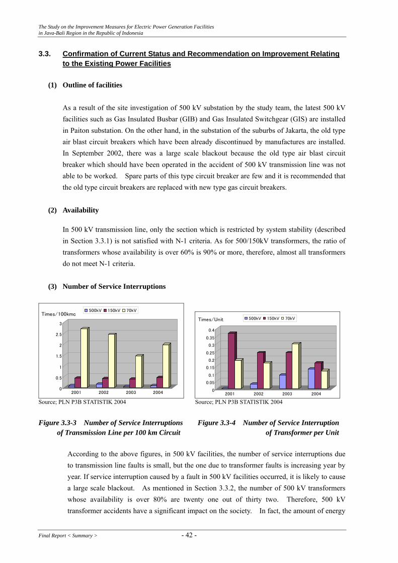
The Study on the Improvement Measures for Electric Power Generation Facilities in Java-Bali Region in the Republic of Indonesia
3.3. Confirmation of Current Status and Recommendation on Improvement Relating to the Existing Power Facilities
(1) Outline of facilities
As a result of the site investigation of 500 kV substation by the study team, the latest 500 kV facilities such as Gas Insulated Busbar (GIB) and Gas Insulated Switchgear (GIS) are installed in Paiton substation. On the other hand, in the substation of the suburbs of Jakarta, the old type air blast circuit breakers which have been already discontinued by manufactures are installed. In September 2002, there was a large scale blackout because the old type air blast circuit breaker which should have been operated in the accident of 500 kV transmission line was not able to be worked. Spare parts of this type circuit breaker are few and it is recommended that the old type circuit breakers are replaced with new type gas circuit breakers.
(2) Availability
In 500 kV transmission line, only the section which is restricted by system stability (described in Section 3.3.1) is not satisfied with N-1 criteria. As for 500/150kV transformers, the ratio of transformers whose availability is over 60% is 90% or more, therefore, almost all transformers do not meet N-1 criteria.
(3) Number of Service Interruptions
0
0.5
1
1.5
2
2.5
3
Times/100kmc
2001 2002 2003 2004
500kV 150kV 70kV
0
0.05
0.1
0.15
0.2
0.25
0.3
0.35
0.4
Times/Unit
2001 2002 2003 2004
500kV 150kV 70kV
Source; PLN P3B STATISTIK 2004 Source; PLN P3B STATISTIK 2004 Figure 3.3-3 Number of Service Interruptions Figure 3.3-4 Number of Service Interruption of Transmission Line per 100 km Circuit of Transformer per Unit
According to the above figures, in 500 kV facilities, the number of service interruptions due to transmission line faults is small, but the one due to transformer faults is increasing year by year. If service interruption caused by a fault in 500 kV facilities occurred, it is likely to cause a large scale blackout. As mentioned in Section 3.3.2, the number of 500 kV transformers whose availability is over 80% are twenty one out of thirty two. Therefore, 500 kV transformer accidents have a significant impact on the society. In fact, the amount of energy
Final Report < Summary > - 42 -

The Study on the Improvement Measures for Electric Power Generation Facilities in Java-Bali Region in the Republic of Indonesia
not supplied in 2004 increased by 2.5% from the previous year 2003, although the number of service interruptions in 2004 is 13% smaller that in 2003. Considering these situations as well as the availability described in Section 3.3.2, 500 kV transformers have to be expanded.
(4) Frequency
According to the information acquired in the site investigation, generators owned by IPPs and PLN (Muara Tawar 3.1, 3.2, 3.3, 4.1, 4.2, 4.3) are operated with governor free mode, but generators owned by IP and PJB do not carry out governor free operation. Therefore, it is IPP and some of Muara Tawar that control frequency in short period. ATURAN JARINGAN Java-Madura-Bali regulates that all power stations have to be operated with governor free mode. In addition, P3B UBOS instructed each power station to operate with governor free mode. In order to keep frequency stable, it is recommended that these generators of IP and PJB are operated with governor free.
- 43 - Final Report < Summary >

The Study on the Improvement Measures for Electric Power Generation Facilities in Java-Bali Region in the Republic of Indonesia
4. Rehabilitation, Modification and Repowering Plans based on Existing
Facilities 4.1. Thermal Power Stations 4.1.1. Technical Study
(1) Tambak Lorok PLTU#1 Combined Cycle Conversion Plan
The basic design figures of the main components of the plan are as follows:-
GT& Generator ; F-Type Gas Turbine, 240 MW Capacity at 30°C Gas/HSD Dual Firing, DLN*1 for Gas & Water Injection for HSD*2
282 kVA Generator and Step-up Transformer
◊
◊ HRSG ; One Drum Type, Steam Condition 88 kg/cm2g × 510°C
◊ Existing STs & Generators ; Single-flow Condensing Type Steam Turbines, 50MW Capacity × 2 sets Rehabilitation of Turbine Rotor and Renewal of Governor
◊ Existing ST Generators & Step-up Transformers ;
Capacity 60kVA × 2sets, Rehabilitation of Stator Coil Rewinding
Instrument & Control Systems ; C/C Operation System ◊
Major BOP; BFPs (Boiler feedwater Pumps), Steam & Water Piping and Valves
◊
Electrical Equipments & S/S ; Conventional Type (150kV Connection) ◊ *1) DLN: Dry Low NOx Combustion *2) HSD: High Speed Diesel Oil
The summary of the repowering plan; ① Repowering; 186.4MW ② EPC cost; 159.3 Million US$
(2) Grati Block II PLTGs Combined Cycle Conversion Plan
The basic design figures of the main components of the plan are basically same as Block I and are as follows:-
◊ Existing GT & Generator ;
701D-Type × 3 sets, Gas/HSD Dual Firing Capacity 112.45MW for Gas, 100.75MW for HSD at 32°C Generator & Step-up Transformer 135 kVA × 3 sets
Final Report < Summary > - 44 -
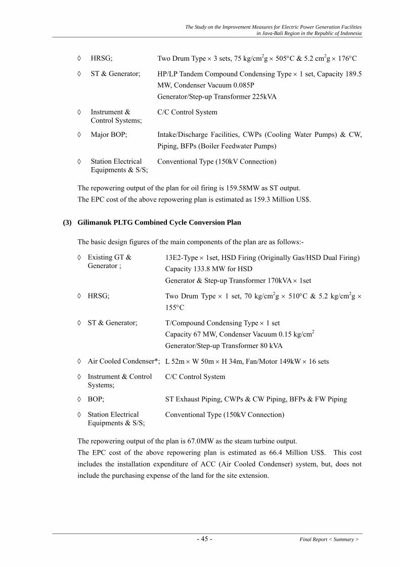
The Study on the Improvement Measures for Electric Power Generation Facilities in Java-Bali Region in the Republic of Indonesia
◊ HRSG; Two Drum Type × 3 sets, 75 kg/cm2g × 505°C & 5.2 cm2g × 176°C
◊ ST & Generator; HP/LP Tandem Compound Condensing Type × 1 set, Capacity 189.5MW, Condenser Vacuum 0.085P Generator/Step-up Transformer 225kVA
◊ Instrument & Control Systems;
C/C Control System
◊ Major BOP; Intake/Discharge Facilities, CWPs (Cooling Water Pumps) & CW, Piping, BFPs (Boiler Feedwater Pumps)
Station Electrical ◊ Equipments & S/S;
Conventional Type (150kV Connection)
The repowering output of the plan for oil firing is 159.58MW as ST output. The EPC cost of the above repowering plan is estimated as 159.3 Million US$.
(3) Gilimanuk PLTG Combined Cycle Conversion Plan
The basic design figures of the main components of the plan are as follows:-
◊ Existing GT & Generator ;
13E2-Type × 1set, HSD Firing (Originally Gas/HSD Dual Firing)Capacity 133.8 MW for HSD Generator & Step-up Transformer 170kVA × 1set
HRSG; Two Drum Type × 1 set, 70 kg/cm2g × 510°C & 5.2 kg/cm2g ×155°C
◊
◊ ST & Generator; T/Compound Condensing Type × 1 set Capacity 67 MW, Condenser Vacuum 0.15 kg/cm2
Generator/Step-up Transformer 80 kVA
◊ Air Cooled Condenser*; L 52m × W 50m × H 34m, Fan/Motor 149kW × 16 sets
◊ Instrument & Control Systems;
C/C Control System
◊ BOP; ST Exhaust Piping, CWPs & CW Piping, BFPs & FW Piping
Station Electrical Conventional Type (150kV Connection) ◊ Equipments & S/S;
The repowering output of the plan is 67.0MW as the steam turbine output. The EPC cost of the above repowering plan is estimated as 66.4 Million US$. This cost includes the installation expenditure of ACC (Air Cooled Condenser) system, but, does not include the purchasing expense of the land for the site extension.
- 45 - Final Report < Summary >

The Study on the Improvement Measures for Electric Power Generation Facilities in Java-Bali Region in the Republic of Indonesia
(4) Concept of Oil Reduction Plans
The basic idea of oil reduction plans is based on the followings;
◊ Reduce Oil Consumption Totally per UBP*
◊ Stop the Operation of the Existing Less Heat Efficient Simple Cycle Gas Turbines (PLTGs) and/or Steam Plants (PLTUs) within the UBP’s management territory
◊ Instead of above Stopping Units (as the alternative plant), ① To convert the Existing GTs to a Higher Efficient Combined Cycle Plant, this means a
Conversion-type Repowering Plan, or, ② To install a newly Higher Efficient Combined Cycle Plant, this means a Scrap &
Build-type Repowering Plan
(5) UBP Semarang Oil Reduction Plan
UBP Semarang manages and controls the following thermal power stations and their power units. The following oil reduction scheme will be born;
◊ Less Efficient Oil Firing Plants to be stopped T.Lorok PLTU #1& #2 (MFO Firing) 50MW × 2 units Sunyaragi PLTG #1- #4(HSD Firing) 20MW × 4 units Cilacap PLTG #1& #2(HSD Firing) 26MW + 29MW Total Capacity of above Stopping Plants 235MW
◊ An Alternative Combined Cycle Plant to be newly installed F-type GT+HRSG+ST/Generator PLTGU (1-1-1) C/C Output at HSD Firing 307.4MW
◊ Repowering & Oil Consumption Reduction to be obtained Repowering (307.4 – 235 = 72.4) 72.4MW Oil Reduction PLTGU Consumption < Stopping Plants Consumption
The basic specification data of the alternative C/C Plant (1-1-1) is as follows;
◊ GT& Generator ; F-Type, Capacity 240MW at 30°C Gas/HSD Dual Firing with Low NOx Combustor Generator & Step-up Transformer 285 kVA
◊ HRSG; RH & Three Drums Type, Steam Condition 110 kg/cm2g ×538/566°C
◊ ST& Generator; RH T/C Condensing Type, ST Capacity 133MW, Generator & step-up Transformer 160kVA
◊ Instrument & Control Systems;
C/C Control System
Final Report < Summary > - 46 -

The Study on the Improvement Measures for Electric Power Generation Facilities in Java-Bali Region in the Republic of Indonesia
◊ BOP; Intake & Discharge Water Facilities, Steam & FeedwaterPiping and Valves
◊ Electrical Equipments & S/S; Conventional Type (150kV Connection)
This combined cycle PLTGU (1-1-1) will be proposed to be installed at the open space area now being used as the football field next to the existing PLTU#3 unit.
The performance data of the alternative C/C Plant will be as follows; Gas Firing GT Output 236.9MW ST Output 133.0MW Plant Output 369.9MW Plant Efficiency 56.4% (LHV) HSD Firing GT Output 206.4MW ST Output 101.0MW Plant Output 307.4MW Plant Efficiency 50.4% (LHV)
(6) UBP Perak/Grati Oil Reduction Plan
UBP Perak/Grati manages and controls both of Perak and Grati Power Stations and their Power Units. The following oil reduction scheme will be born;
◊ Less Efficient Oil Existing Plants to be stopped. Perak PLTU#3 (MFO Firing) 50MW × 2 units
◊ Grati BLK II PLTG#1-#3 101.90MW × 3units to be converted into a higher efficient Alternative Combined Cycle Plant.
Newly Installed HRSG × 3+ST/Generator × 1 PLTGU (3-3-1) C/C Output at HSD Firing 461.83MW
The Basic Specification of Grati BLK II PLTGU (3-3-1) is as follows;
Existing GT& Generator ; 701D-Type × 3 sets, Gas/HSD Dual Firing Capacity 112.45MW for Gas, 100.75MW for HSD at 32°C
◊
HRSG; Two Drum Type × 3 sets, 75 kg/cm2g × 505°C T & 5.2kg/cm2g × 176°C
◊
ST& Generator; HP/LP T/Compound Condensing Type × 1 set, Capacity 189.5MW, Condenser Vacuum 0.085ata
◊
◊ Instrument & Control Systems; C/C control system
◊ BOP; Intake/Discharge Facilities, CWPs & CW Piping, BFPs & Piping
- 47 - Final Report < Summary >

The Study on the Improvement Measures for Electric Power Generation Facilities in Java-Bali Region in the Republic of Indonesia
Station Electrical Equipments Conventional Type (150kV Connection) ◊ & S/S;
It is noted that Grati Block II PLTGU (3-3-1) Specification is just same as Block I (3-3-1).
Then, HSD firing performance of Grati Block II Alternative C/C is the same as Block I. ◊ GT/ST Output 100.75MW × 3/159.58MW ◊ Plant Output 461.83MW ◊ Plant Thermal Efficiency 47.1% (LHV)
(7) UBP Bali Oil Reduction Plan
UBP Bali manages and controls three thermal power stations and the grid power from Java Island.
The following oil reduction scheme will be born;
◊ Less Efficient Oil Fired Existing Plants to be stopped. Pesanggaran PLTG #1& #2 (HSD Firing) 21.4+20.1MW Pesanggaran PLTD #1- #4 (HSD Firing) 5.08MW × 4 ◊ Gilimanuk PLTG to be converted to a Higher Efficient Alternative Combined Cycle Plant. One Newly Installed HRSG + One ST/Generator PLTGU (1-1-1) C/C Output at HSD Firing 200MW ◊ Repowering & Oil Consumption Reduction to be obtained. Repowering 67.0 – (41.5+ 20.3) = 5.2 5.2MW Oil Reduction; Oil Consumption by Stopping Plants
The basic design figures of the main components of the plan are as follows:-
Existing GT& Generator ; 13E2-Type × 1 set, HSD Firing (Originally Gas/HSD Dual Firing), Capacity 133MW for HSD
◊
HRSG; Two Drum Type × 1 set, 70 kg/cm2g × 510°C & 5.2kg/cm2g × 155°C
◊
ST& Generator; T/Compound Condensing Type × 1 set, Capacity 67MW, Condenser Vacuum 0.15P
◊
Air Cooled Condenser* L 52m × W 50m × H 34m Structure and Cooling Surfaces, Fan/Motor 149kW × 16 sets
◊
Instrument & Control Systems; C/C Control System ◊
BOP; ST Exhaust Piping, CWPs & CW Piping, BFPs & FW Ping
◊
Station Electrical Equipments & S/S; Conventional Type (150kV Connection) ◊
Final Report < Summary > - 48 -

The Study on the Improvement Measures for Electric Power Generation Facilities in Java-Bali Region in the Republic of Indonesia
4.1.2. Economic Financial Analysis
(1) Proposed Repowering Plans
Table 4.1-5 Outline of Proposed Plans Case Final Plans Fuel
Type Proposed Plan Investment Cost No. (Additional Output)
1 Conversion to C/C (PLTGU 1-1-2) by utilizing existing PLTU #1 and adding one (1) GT & one (1) HRSG
1.1
HSD GT output ST output Plant output Plant efficiency
206.4 MW 40.0 MW × 2 units
286.4 MW 47.0 % (LHV base)
179.0 M.US$ (186.4 MW)
1.2
Tambak Lorok
Gas GT output ST output Plant output Plant efficiency
236.9 MW 50.7 MW × 2 units
338.3 MW 51.6 % (LHV base)
179.0 M.US$ (238.3 MW)
2 Conversion to C/C (PLTGU 3-3-1) by utilizing existing BLK 2 PLTG #1, #2 and #3, and adding three (3) HRSG & one (1) ST
2.1 HSD GT output ST output Plant output Plant efficiency
100.75 MW × 3 units 159.58 MW 461.83 MW 47.1 % (LHV base)
179.0 M.US$ (120.3 MW)
2.2
Grati
Gas GT output ST output Plant output Plant efficiency
112.45 MW × 3 units 189.5 MW 526.85 MW 49.8 % (LHV base)
179.0 M.US$ (185.4 MW)
3 Conversion to C/C (PLTGU 1-1-1) by utilizing existing PLTG and adding one (1) HRSG & one (1) ST
3.1
Gilimanuk
HSD GT output ST output Plant output Plant efficiency
133.00 MW 67.00 MW
200.00 MW 49.6 % (LHV base)
74.6 M.US$ (66.2 MW)
4 New C/C (PLTGU 1-1-1) consisting of a new large GT, one HRSG and one ST.
4.1 HSD GT output ST output Plant output Plant efficiency
206.4 MW 101.0 MW 307.4 MW 50.4 % (LHV base)
238.6 M.US$ (72.4 MW)
4.2
UBP Semarang Shutdown of Tambak Lorok PLTU #1 & #2 (50 MW each) and also shutdown of Sunyaragi #1~#4 (20 MW each) and Cilacap PLTG #1 & #2 (29 MW and 26 MW each)
Gas GT output ST output Plant output Plant efficiency
236.9 MW 133.0 MW 369.9 MW 56.4 % (LHV base)
238.6 M.US$ (134.0 MW)
5 Conversion to C/C (PLTGU 3-3-1) by utilizing of Grati BLK 2 PLTG #1~#3 and adding three (3) HRSG and one (1) ST. Shutdown of Perak PLTU #3 and #4.
5.1 HSD GT output ST output Plant output Plant efficiency
100.75 MW x 3 units 159.58 MW 461.83 MW 47.1 % (LHV base)
179.0 M.US$ (20.3 MW)
5.2
UBP Grati and Perak Shutdown of Perak PLTU #3 (50 MW) & #4 (50 MW)
Gas GT output ST output Plant output Plant efficiency
112.45 MW x 3 units 189.5 MW 526.85 MW 49.8 % (LHV base)
179.0 M.US$ (85.4 MW)
6 Conversion to C/C (PLTGU 1-1-1) by utilizing existing Gilimanuk GT and adding one HRSG and one ST. Shutdown of Pesanggaran PLTG #1 and #2
6.1
UBP Bali 4
Shutdown of Pesanggaran PLTG #1 (21 MW) & #2 (20 MW) HSD GT output
ST output Plant output Plant efficiency
133.00 MW 74.6 M.US$ 67.00 MW
200.00 MW (25.2 MW) 49.6 % (LHV base)
4 There seems to be possibility of shutdown of Pesanggaran PLTD #1 ~ #4.
- 49 - Final Report < Summary >
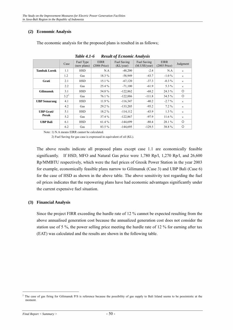
The Study on the Improvement Measures for Electric Power Generation Facilities in Java-Bali Region in the Republic of Indonesia
(2) Economic Analysis
The economic analysis for the proposed plans is resulted in as follows;
Table 4.1-6 Result of Ecnomic Analysis
Case Fuel Type (new plans)
EIRR (2006 Price)
Fuel Saving (KL/year)
Fuel Saving(M.US$/year)
EIRR (2003 Price) Judgment
1.1 HSD N.A -48,200 -2.4 N.A × Tambak Lorok 1.2 Gas 18.3 % -58,949 -43.7 -1.0 % ×
2.1 HSD 15.1 % -67,120 -37.3 -0.3 % × Grati 2.2 Gas 25.4 % -71,100 -61.9 5.3 % × 3.1 HSD 54.8 % -122,862 -68.2 24.3 % Gilimanuk 3.25 Gas 76.1 % -122,886 -111.8 34.5 % 4.1 HSD 11.9 % -116,347 -40.2 -2.7 % × UBP Semarang 4.2 Gas 29.2 % -133,205 -95.2 7.2 % × 5.1 HSD 18.2 % -114,112 -43.9 1.3 % × UBP Grati/
Perak 5.2 Gas 37.4 % -122,867 -97.9 11.6 % × 6.1 HSD 61.4 % -144,699 -80.4 28.1 % UBP Bali
6.2 Gas 83.5 % -144,695 -129.5 38.8 %
Note: 1) N.A means EIRR cannot be calculated. 2) Fuel Saving for gas case is expressed in equivalent of oil (KL).
The above results indicate all proposed plans except case 1.1 are economically feasible significantly. If HSD, MFO and Natural Gas price were 1,780 Rp/l, 1,270 Rp/l, and 26,600 Rp/MMBTU respectively, which were the fuel prices of Gresik Power Station in the year 2003 for example, economically feasible plans narrow to Gilimanuk (Case 3) and UBP Bali (Case 6) for the case of HSD as shown in the above table. The above sensitivity test regarding the fuel oil prices indicates that the repowering plans have had economic advantages significantly under the current expensive fuel situation.
(3) Financial Analysis
Since the project FIRR exceeding the hurdle rate of 12 % cannot be expected resulting from the above annualised generation cost because the annualized generation cost does not consider the station use of 5 %, the power selling price meeting the hurdle rate of 12 % for earning after tax (EAT) was calculated and the results are shown in the following table.
5 The case of gas firing for Gilimanuk P/S is reference because the possibility of gas supply to Bali Island seems to be pessimistic at the
moment.
Final Report < Summary > - 50 -
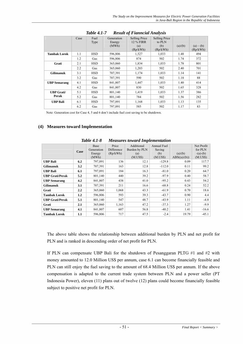
The Study on the Improvement Measures for Electric Power Generation Facilities in Java-Bali Region in the Republic of Indonesia
Table 4.1-7 Result of Fianncial Analysis Case Fuel
Type Generation
Energy (MWh)
Selling Price 12 % FIRR
(a) (Rp/kWh)
Selling Price to PLN
(b) (Rp/kWh)
(a)/(b)
(a) – (b) (Rp/kWh)
1.1 HSD 596,806 1,527 1,033 1.48 494 Tambak Lorok 1.2 Gas 596,806 874 502 1.74 372 2.1 HSD 365,060 1,834 1,033 1.78 801 Grati 2.2 Gas 365,060 1,203 502 2.40 701 3.1 HSD 707,391 1,174 1,033 1.14 141 Gilimanuk 3.2 Gas 707,391 590 502 1.18 88 4.1 HSD 841,807 1,447 1,033 1.40 414 UBP Semarang 4.2 Gas 841,807 830 502 1.65 328 5.1 HSD 801,140 1,419 1,033 1.37 386 UBP Grati/
Perak 5.2 Gas 801,140 784 502 1.56 282 6.1 HSD 797,891 1,168 1,033 1.13 135 UBP Bali 6.2 Gas 797,891 585 502 1.17 83
Note: Generation cost for Case 4, 5 and 6 don’t include fuel cost saving to be shutdown.
(4) Measures toward Implementation
Table 4.1-8 Measures toward Implementation
Case
Base Generation
Energy (MWh)
Price Difference(Rp/kWh)
Additional Burden by PLN
(a) (M.US$)
Annual Fuel Saving
(b) (M.US$)
(a)/(b) ABS((a)/(b))
Net Profit for PLN -(a)-(b)
(M.US$) UBP Bali 6.2 797,891 136 12.1 -129.8 0.09 117.7Gilimanuk 3.2 707,391 163 12.8 -112.0 0.11 99.2UBP Bali 6.1 797,891 184 16.3 -81.0 0.20 64.7UBP Grati/Perak 5.2 801,140 440 39.2 -97.9 0.40 58.7UBP Semarang 4.2 841,807 438 41.0 -95.2 0.43 54.2Gilimanuk 3.1 707,391 211 16.6 -68.8 0.24 52.2Grati 2.2 365,060 1,068 43.3 -61.9 0.70 18.6Tambak Lorok 1.2 596,806 593 39.3 -43.7 0.90 4.4UBP Grati/Perak 5.1 801,140 547 48.7 -43.9 1.11 -4.8Grati 2.1 365,060 1,163 47.2 -37.3 1.27 -9.9UBP Semarang 4.1 841,807 607 56.8 -40.2 1.41 -16.6Tambak Lorok 596,806 717 47.5 -2.4 19.79 -45.11.1
The above table shows the relationship between additional burden by PLN and net profit for PLN and is ranked in descending order of net profit for PLN.
If PLN can compensate UBP Bali for the shutdown of Pesanggaran PLTG #1 and #2 with money amounted to 12.0 Million US$ per annum, case 6.1 can become financially feasible and PLN can still enjoy the fuel saving to the amount of 68.4 Million US$ per annum. If the above compensation is adapted to the current trade system between PLN and a power seller (PT Indonesia Power), eleven (11) plans out of twelve (12) plans could become financially feasible subject to positive net profit for PLN.
- 51 - Final Report < Summary >
The Study on the Improvement Measures for Electric Power Generation Facilities in Java-Bali Region in the Republic of Indonesia
(5) Conclusion and Recommendation
Based on the economic and financial analyses, conclusion and recommendation are as follows;
1) All repowering plans except case 1 resulted in economically feasible. PLN can expect to save a large amount of oil, which leads to reduction of generation cost and financial burden of PLN as a power purchaser. The higher fuel prices rise, the higher EIRR is expected. Furthermore, the saved amount of fuel can be allocated to other industries for further production or to export to gain more hard currencies. However, all repowering plans resulted in financially not feasible under the current average power selling prices.
2) “Economically feasible and financially not feasible” might be interpreted as the current power selling prices6 to PLN are rather low taken account of expensive fuel.
3) If PLN can compensate for the UBP involved in shutdown with money of part of fuel saving, most repowering plans could be financially feasible and the both parties, a seller and a buyer, could share the profits by implementation of repowering/oil reduction plans.
4) Economic and financial analyses indicated that UBP Bali (Case 6) was the most attractive plans. Therefore, the implementation of case 6 is strongly recommended.
5) Under the current fuel situation in Indonesia, the concept of proposed repowering/oil reduction might indicate the future directional movement relating to oil fired thermal stations in parallel with the promotion of the new crash program.
6) Concerning rehabilitation/modification plans to improve the reliability of operation mainly, utilization of export credit as mentioned in Section 2.5 is recommended.
4.1.3. Environmental and Social Consideration
This section evaluates the environmental burden relating to rehabilitation/modification and repowering plans for the existing power generation facilities. Concerning the thermal power stations, rehabilitation and modification plans, such as restoring the capacity and/or replacement of power facilities, are already planned by IP, PJB and PLN and some repowering plans are proposed by the JICA Study Team. And it seems there are not any issues to be considered form the viewpoint of environmental and social consideration in respect of “Improvement Measures for Operation and Maintenance for the existing power generation facilities”.
6 Power tariff rate for consummers has not been changed since 2003 by the President Decree No. 104.
Final Report < Summary > - 52 -

The Study on the Improvement Measures for Electric Power Generation Facilities in Java-Bali Region in the Republic of Indonesia
(1) Environmental Impact Scoping relating to Repowering Plans
Proposed repowering plans are all conversion plans from the existing plants to PLTGU for Tambak Lorok Power Station, Grati Power Station and Gilimanuk Power Station. In combination with these power stations, oil reduction plans are also proposed in manner of shutdown of the existing lower thermal efficiency plants by UBP basis. The outline of the proposed plans is as mentioned in Section 4.1.1.
1) Each Repowering Plans
Outline of repowering plan, envisaged environmental impact and surrounding condition for each repowering plan are as follows.
Tambak Lorok Power Station -Outline-
The existing PLTU boilers for unit 1 and unit 2 will be removed. One gas turbine and one HRSG will be newly constructed. In combination with the existing two steam turbines and generators, the existing plants are converted to PLTGU (1-1-2). PLTGU will be designed as dual firing of gas and HSD as well as the existing PLTGU. However, it seems to be unforeseeable to promote the repowering plan by gas firing.
-Environmental Impact- The amount of combustion gas would be more than that of existing two boilers. However, if a new gas turbine adopts the low NOx combustion technology, the total pollutant amount consisting of SOx, NOx, dust and so on seem to be not increased. Since the power output of steam turbine does not increase, the thermal effluent from the condenser remains the current level.
-Surrounding Condition- According to the atmospheric monitoring data in 2005, NO2 and dust were lower than the emission standard values and SO2 was close to the upper limit of the emission standard for PLTU unit 1 and unit 2 (no monitoring data for PLTU unit 3). Concerning the water quality monitoring data, water temperatures at intake and outlet indicated 29.5°C and 36.2°C respectively. Field survey conducted in 1999 reported the existence of the avicennia alba near the power station, which is widely observed in south-eastern Asia. Other precious fauna and flora were not identified (IP, 2004 7)
-Others- The ground settlement with about 4 cm per annum occurs at the periphery of the power station and peripheral roads are submerged. The power station is also
7 Indonesia Power, 2004, “ANDAL Revisi Pengembangan PLTGU Tambaklorok I - Semarang”
- 53 - Final Report < Summary >

The Study on the Improvement Measures for Electric Power Generation Facilities in Java-Bali Region in the Republic of Indonesia
sometimes submerged and is forced to stop the operation due to the unavailability of the cooling pump. Tambak Lorok power station seems to be constructed on the reclaimed land and the ground resettlement might occur according to the map.
Grati Power Station -Outline-
The conversion to PLTGU as well as Block I is achieved in manner of adding new three (3) HRSG and one steam turbine/generator to existing three gas turbines in Block II (3-3-1).
-Environmental Impact- Since the amount of fuel consumption will not increase, the total emission also will not increase. However, thermal effluent from the condenser will increase twice as high due to the addition of a new steam turbine.
-Surrounding Condition- According to the atmospheric monitoring data in 2005, NO2, SO2 and dust from the current six (5) gas turbines cleared the emission standard. The air quality at the monitoring point also cleared the air standard. The water temperatures measured in December 2003 at intake and outlet indicated 32.0°C and 35.0°C respectively (IP, 20048). The field survey in 2004 reported the existence of kingfisher race and heron race at the periphery of the power station, of which number has been rather decreased recently worldwide. Other precious fauna and flora were not identified (IP, 20044).
-Others- There seems to be no ecological importance area, such as mangrove, and residential area near the power station. According to the results of scoping as described later, increase of thermal effluent is seems to make the most impact on the ambient surrounding. The AMDAL approved in March 2005 for Block III was prepared in manner of adding new Block III to the current Blocks. The AMDAL said that the diffusion of thermal effluent would enlarge within a certain area only. Therefore, the thermal effluent seems to cause minor impact. The new or revised AMDAL for the proposed repowering plan in Block II might not be necessary because the AMDAL in March 2005 for Block III could be utilized for the proposed repowering plan.
Gilimanuk Power Station -Outline-
PLTGU will be achieved in manner of adding one bottoming plant HRSG and one steam turbine/generator to the existing gas turbine (1-1-1).
8 Indonesia Power, 2004, “Review ANDAL PLTGU Grati I & II Pasuruan”
Final Report < Summary > - 54 -

The Study on the Improvement Measures for Electric Power Generation Facilities in Java-Bali Region in the Republic of Indonesia
-Environmental Impact- Since the amount of fuel consumption will not increase, the total emission also will not increase. Emission gas temperature will lower and the concentration on the ground of air contaminant will change accordingly. However, there seems to be no occurrence of environmental issues because the existing plants adopt the low NOx combustion technology although it is necessary to confirm no occurrence of environmental issues by the diffusion simulation of air contaminant. Since the cooling water by seawater seems to be difficult due to the relevant landscape (existing plants are installed at +4 m or more above sea level and the candidate site is located at inland with 1 km far from the seashore.), air cooling condenser is provisionally proposed. The type of cooling system will be further studied in combination with the study on the availability of seawater.
-Surrounding Condition- According to the atmospheric monitoring data in 2004 and 2005 for a gas turbine, NO2, SO2 and dust cleared the emission standard. Field survey conducted in 1997 reported the existence of Biawak (scientific name: Varanus salvator), which belong to Appendix II of Washington Convention. Addition to Biawak, mangrove forest, marine forest and shelf of coral were also identified (PT. PLN, 19989).
-Others- Repowering plan for Gilimanuk requires extension of area to a certain degree because of new installation of steam turbine. The extension of area shall be carefully considered to avoid the adjacent national park, and houses spread in the north of the power station. Because ecological importance sea area, such as mangrove forest and shelf of coral, are spread at the periphery of Gilimanuk power station, study on the thermal effluent impact is required in case of using seawater as cooling water.
2) Oil Reduction Plan
The above power stations involved in the repowering plans are managed by UBP (Unit Bisnis Pembangkitan: Generation Business Unit). The outline of oil reduction plan by UBP basis and envisaged environmental impact is as follows. Since the surrounding conditions and so on for oil reduction plan are the same as those of each repowering plan as mentioned above, the relevant description is omitted here.
UBP Semarang -Outline-
New one-axis PLTGU by F-type GT (1-1-1) will be constructed adjacent to the
9 PT.PLN, 1998, “Analisis Dampak Lingkungan (ANDAL) PLTG Gilimanuk, Bali”
- 55 - Final Report < Summary >
The Study on the Improvement Measures for Electric Power Generation Facilities in Java-Bali Region in the Republic of Indonesia
existing PLTU unit 3. On the other hand, Sunyaragi power station PLTG unit 1 to unit 4, Cilacap power station PLTG unit 1 and 2, which are belonging to UBP Semarang, and Tambak Lorok PLTU unit 1 and unit 2 will be shutdown for the fuel oil saving.
-Environmental Impact- Regarding the amount of combustion gas and total pollutant amount are the same condition as those of above repowering plan. However, since the power output of a new steam turbine proposed in UBP Semarang is bigger than the total power outputs of existing PLTU unit 1 and unit 2 of Tambak Lorok, thermal effluent will increase in compared with the current level. In connection with the shutdown of Sunyaragi and Cilacap power stations, social consideration to the peripheral residents, whose livelihood depend on the power stations, handling of unnecessary power facilities and utilization of empty lots shall be carefully considered.
UBP Perak/Grati -Outline-
Outline of repowering plan is the same as that of Grati power station. Furthermore, Perak PLTU unit 3 and unit 4 belonging to UBP Perak/Grati will be shutdown for the fuel oil saving.
-Environmental Impact- Environmental burden will be decreased in proportion to the shutdown of Perak PLTU unit 3 and unit 4. In connection with the shutdown of Perak power station, social consideration to the peripheral residents, whose livelihood depend on the power station, handling of unnecessary power facilities and utilization of empty lots shall be carefully considered.
UBP/Bali -Outline-
Outline of repowering plan is the same as that of Gilimanuk power station. Furthermore, Pesanggaran PLTG unit 1 and unit 2 and possibility of PLTD unit 1 to unit 4 will be shutdown for the fuel oil saving.
-Environmental Impact- Environmental burden will be decreased in proportion to the shutdown of Pesanggaran PLTG unit 1 and unit 2 and PLTD unit 1 to unit 4. In connection with the shutdown of parts of Pesanggaran power station, social consideration to the peripheral residents, whose livelihood depend on the power station, handling of unnecessary power facilities and utilization of empty lots shall be carefully considered.
Final Report < Summary > - 56 -

The Study on the Improvement Measures for Electric Power Generation Facilities in Java-Bali Region in the Republic of Indonesia
Based on the consultation with the environmental staff in the IP head office regarding the proposed repowering plans, the scoping for environmental burden was prepared provisionally. Table 4.1-14 shows the scoping relating to repowering plans and Table 4.1-15 shows the scoping relating to the combination of repowering and oil reduction plans.
(2) Required Investigation toward Implementation
Based on the results of scoping about proposed repowering and oil reduction plans, the following items deem to be required investigation toward the implementation of proposed plans.
Tambak Lorok Power Station Items Assessment Procedure Survey Items
Air Quality Pollution Prediction - Meteorological Investigation (Air Temperature, Humidity, Wind Direction, Wind Velocity, Atmospheric Stability, etc.)
- Parameters of Exhaust Gas (Amount of Emission, Temperature of Exhaust Gas, etc.)
Water Quality - - Taking the cooling water - - Soil and Ground Situation and Forecast of Ground Settlement - Leveling
- Drilling Survey (Geologic Condition, Type of Soil, etc.) Fauna and Flora - - Endangered Species - - Noise and Vibration Prediction of Noise and Vibration - Survey of Noise and Vibration
- Equipment Noise Level and Vibration Level Waste - - Offensive Odor - - Population and Industry - - Poverty Group and Ethnic Tribes - -
Water Usage - - Protective Zone - - Cultural Facilities - - Sanitary Conditions - - Landscape - - Land Usage - - Impacts during Construction -Living and Livelihood -Air Pollution -Water Pollution -Noise and Vibration
- Reduction Measures - Proper Plan at Construction Period - Education to worker - Selection of Construction Machine - Others (Water Spray, Installation of Portable
Toilets, etc.)
- Use of Optimization Technique (For instance PERT
Technique) - Conduct of Monitoring Study during Construction Period
(Population, Industry, Air Quality, Water Quality, Noise and Vibration, etc.)
Grati Power Station
Assessment Procedure Survey Items Items Air Quality - - Water Quality - - Taking the cooling water - - Soil and Ground - - Fauna and Flora - - Endangered Species - - Noise and Vibration Prediction of Noise and Vibration - Survey of Noise and Vibration
- Equipment Noise Level and Vibration Level
- 57 - Final Report < Summary >

The Study on the Improvement Measures for Electric Power Generation Facilities in Java-Bali Region in the Republic of Indonesia
Assessment Procedure Survey Items Items Waste - - Offensive Odor - - Population and Industry - - Poverty Group and Ethnic Tribes - -
Water Usage - - Protective Zone - - Cultural Facilities - - Sanitary Conditions - - Landscape - - Land Usage - - Impacts during Construction - Conflict of Interests -Living and Livelihood -Air Pollution -Water Pollution -Noise and Vibration
- Understanding of Consideration of Resident to
Power Station - Reduction Measures - Proper Plan at Construction Period
- Attitude Survey to Power Station (Survey by
Questionnaire) - Use of Optimization Technique (For instance PERT
Technique) - Education to worker - Conduct of Monitoring Study during Construction Period
(Population, Industry, Air Quality, Water Quality, Noise and Vibration, etc.)
- Selection of Construction Machine - Others (Water Spray, Installation of Portable
Toilets, etc.)
Gilimanuk Power Station
Items Assessment Procedure Survey Items Air Quality - - Water Quality Diffusion Prediction of Thermal Effluent - Hydrographic Investigation (Water Temperature, Current
Direction, Current Velocity, etc.) - Meteorological Investigation (Air Temperature, Humidity,
Wind Velocity, Cloud Cover, etc.) - Investigation of Organism (Sessile Organisms,
Vegetation, etc.) - Parameters of Thermal Effluent (Amount of Discharge,
Temperature of Thermal Effluent) Taking the cooling water Prediction of intake of plankton Investigation of Organism (Plankton) Soil and Ground - - Fauna and Flora Examination of Additional Site Investigation of Land Usage (Mangrove, etc.) Endangered Species - - Noise and Vibration Prediction of Noise and Vibration - Survey of Noise and Vibration
- Equipment Noise Level and Vibration Level Waste - - Offensive Odor - - Population and Industry - - Poverty Group and Ethnic Tribes
Examination of possibility about unfairly distribution between Bali Native and Java People
Social Investigation (Industrial Structure, Employed Workforce, etc.)
Water Usage Prediction of Volume of intake Water Survey of Water Usage (Fisheries Industry, etc.) Protective Zone Diffusion Prediction of Thermal Effluent - Hydrographic Investigation (Water Temperature, Current
Direction, Current Velocity, etc.) - Meteorological Investigation (Air Temperature, Humidity,
Wind Velocity, Cloud Cover, etc.) - Investigation of Organism (Sessile Organisms,
Vegetation, etc.) - Parameters of Thermal Effluent (Amount of Discharge,
Temperature of Thermal Effluent) Cultural Facilities - - Sanitary Conditions - - Landscape Prediction of Scenery Situation and Prediction of Scenery Land Usage Examination of Additional Site Investigation of Land Usage (residential land, etc.) Impacts during Construction ・Living and Livelihood ・Air Pollution ・Water Pollution ・Noise and Vibration
- Reduction Measures
- Use of Optimization Technique (For instance PERT
Technique) - Proper Plan at Construction Period - Education to worker - Selection of Construction Machine
- Conduct of Monitoring Study during Construction Period (Population, Industry, Air Quality, Water Quality, Noise
Final Report < Summary > - 58 -
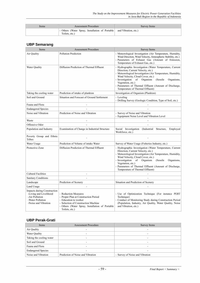
The Study on the Improvement Measures for Electric Power Generation Facilities in Java-Bali Region in the Republic of Indonesia
Assessment Procedure Survey Items Items - Others (Water Spray, Installation of Portable
Toilets, etc.) and Vibration, etc.)
UBP Semarang
Items Assessment Procedure Survey Items Air Quality Pollution Prediction - Meteorological Investigation (Air Temperature, Humidity,
Wind Direction, Wind Velocity, Atmospheric Stability, etc.)- Parameters of Exhaust Gas (Amount of Emission,
Temperature of Exhaust Gas, etc.) Water Quality Diffusion Prediction of Thermal Effluent - Hydrographic Investigation (Water Temperature, Current
Direction, Current Velocity, etc.) - Meteorological Investigation (Air Temperature, Humidity,
Wind Velocity, Cloud Cover, etc.) - Investigation of Organism (Sessile Organisms,
Vegetation, etc.) - Parameters of Thermal Effluent (Amount of Discharge,
Temperature of Thermal Effluent) Taking the cooling water Prediction of intake of plankton Investigation of Organism (Plankton) Soil and Ground Situation and Forecast of Ground Settlement - Leveling
- Drilling Survey (Geologic Condition, Type of Soil, etc.) Fauna and Flora - - Endangered Species - - Noise and Vibration Prediction of Noise and Vibration - Survey of Noise and Vibration
- Equipment Noise Level and Vibration Level Waste - - Offensive Odor - - Population and Industry Examination of Change in Industrial Structure Social Investigation (Industrial Structure, Employed
Workforce, etc.) Poverty Group and Ethnic Tribes - -
Water Usage Prediction of Volume of intake Water Survey of Water Usage (Fisheries Industry, etc.) Protective Zone Diffusion Prediction of Thermal Effluent - Hydrographic Investigation (Water Temperature, Current
Direction, Current Velocity, etc.) - Meteorological Investigation (Air Temperature, Humidity,
Wind Velocity, Cloud Cover, etc.) - Investigation of Organism (Sessile Organisms,
Vegetation, etc.) - Parameters of Thermal Effluent (Amount of Discharge,
Temperature of Thermal Effluent) Cultural Facilities - - Sanitary Conditions - - Landscape Prediction of Scenery Situation and Prediction of Scenery Land Usage - - Impacts during Construction -Living and Livelihood -Air Pollution -Water Pollution -Noise and Vibration
- Reduction Measures - Proper Plan at Construction Period - Education to worker - Selection of Construction Machine - Others (Water Spray, Installation of Portable
Toilets, etc.)
- Use of Optimization Technique (For instance PERT
Technique) - Conduct of Monitoring Study during Construction Period
(Population, Industry, Air Quality, Water Quality, Noise and Vibration, etc.)
UBP Perak-Grati
Assessment Procedure Survey Items Items Air Quality - - Water Quality - - Taking the cooling water - - Soil and Ground - - Fauna and Flora - - Endangered Species - - Noise and Vibration Prediction of Noise and Vibration - Survey of Noise and Vibration
- 59 - Final Report < Summary >

The Study on the Improvement Measures for Electric Power Generation Facilities in Java-Bali Region in the Republic of Indonesia
Items Assessment Procedure Survey Items - Equipment Noise Level and Vibration Level
Waste - - Offensive Odor - - Population and Industry Examination of Change in Industrial Structure Social Investigation (Industrial Structure, Employed
Workforce, etc.) Poverty Group and Ethnic Tribes - -
Water Usage - - Protective Zone - - Cultural Facilities - - Sanitary Conditions - - Landscape Prediction of Scenery Situation and Prediction of Scenery Land Usage - - Impacts during Construction - Conflict of Interests -Living and Livelihood -Air Pollution -Water Pollution -Noise and Vibration
- Understanding of Consideration of Resident to
Power Station - Reduction Measures - Proper Plan at Construction Period
- Attitude Survey to Power Station (Survey by
Questionnaire) - Use of Optimization Technique (For instance PERT
Technique) - Education to worker - Conduct of Monitoring Study during Construction Period
(Population, Industry, Air Quality, Water Quality, Noise and Vibration, etc.)
- Selection of Construction Machine - Others (Water Spray, Installation of Portable
Toilets, etc.)
UBP Bali
Items Assessment Procedure Survey Items Air Quality - - Water Quality Diffusion Prediction of Thermal Effluent - Hydrographic Investigation (Water Temperature, Current
Direction, Current Velocity, etc.) - Meteorological Investigation (Air Temperature,
Humidity, Wind Velocity, Cloud Cover, etc.) - Investigation of Organism (Sessile Organisms,
Vegetation, etc.) - Parameters of Thermal Effluent (Amount of Discharge,
Temperature of Thermal Effluent) Taking the cooling water Prediction of intake of plankton Investigation of Organism (Plankton) Soil and Ground - - Fauna and Flora Examination of Additional Site Investigation of Land Usage (Mangrove, etc.) Endangered Species - - Noise and Vibration Prediction of Noise and Vibration - Survey of Noise and Vibration
- Equipment Noise Level and Vibration Level Waste - - Offensive Odor - - Population and Industry Examination of Change in Industrial Structure Social Investigation (Industrial Structure, Employed
Workforce, etc.) Poverty Group and Ethnic Tribes
Examination of possibility about unfairly distribution between Bali Native and Java People
Social Investigation (Industrial Structure, Employed Workforce, etc.)
Water Usage Prediction of Volume of intake Water Survey of Water Usage (Fisheries Industry, etc.) Protective Zone Diffusion Prediction of Thermal Effluent - Hydrographic Investigation (Water Temperature, Current
Direction, Current Velocity, etc.) - Meteorological Investigation (Air Temperature,
Humidity, Wind Velocity, Cloud Cover, etc.) - Investigation of Organism (Sessile Organisms,
Vegetation, etc.) - Parameters of Thermal Effluent (Amount of Discharge,
Temperature of Thermal Effluent) Cultural Facilities - - Sanitary Conditions - - Landscape Prediction of Scenery Situation and Prediction of Scenery Land Usage Examination of Additional Site Investigation of Land Usage (residential land, etc.) Impacts during Construction ・Living and Livelihood
- Reduction Measures
- Use of Optimization Technique (For instance PERT
Final Report < Summary > - 60 -
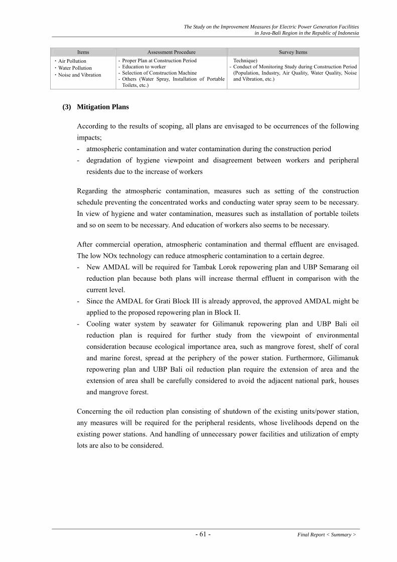
The Study on the Improvement Measures for Electric Power Generation Facilities in Java-Bali Region in the Republic of Indonesia
Items Assessment Procedure Survey Items
・Air Pollution ・Water Pollution ・Noise and Vibration
- Proper Plan at Construction Period Technique) - Education to worker - Conduct of Monitoring Study during Construction Period
(Population, Industry, Air Quality, Water Quality, Noise and Vibration, etc.)
- Selection of Construction Machine - Others (Water Spray, Installation of Portable
Toilets, etc.)
(3) Mitigation Plans
According to the results of scoping, all plans are envisaged to be occurrences of the following impacts; - atmospheric contamination and water contamination during the construction period - degradation of hygiene viewpoint and disagreement between workers and peripheral
residents due to the increase of workers
Regarding the atmospheric contamination, measures such as setting of the construction schedule preventing the concentrated works and conducting water spray seem to be necessary. In view of hygiene and water contamination, measures such as installation of portable toilets and so on seem to be necessary. And education of workers also seems to be necessary.
After commercial operation, atmospheric contamination and thermal effluent are envisaged. The low NOx technology can reduce atmospheric contamination to a certain degree. - New AMDAL will be required for Tambak Lorok repowering plan and UBP Semarang oil
reduction plan because both plans will increase thermal effluent in comparison with the current level.
- Since the AMDAL for Grati Block III is already approved, the approved AMDAL might be applied to the proposed repowering plan in Block II.
- Cooling water system by seawater for Gilimanuk repowering plan and UBP Bali oil reduction plan is required for further study from the viewpoint of environmental consideration because ecological importance area, such as mangrove forest, shelf of coral and marine forest, spread at the periphery of the power station. Furthermore, Gilimanuk repowering plan and UBP Bali oil reduction plan require the extension of area and the extension of area shall be carefully considered to avoid the adjacent national park, houses and mangrove forest.
Concerning the oil reduction plan consisting of shutdown of the existing units/power station, any measures will be required for the peripheral residents, whose livelihoods depend on the existing power stations. And handling of unnecessary power facilities and utilization of empty lots are also to be considered.
- 61 - Final Report < Summary >

The Study on the Improvement Measures for Electric Power Generation Facilities in Java-Bali Region in the Republic of Indonesia
Table 4.1-14(1) Scoping Results of the Repowering Plan in Tambak Lorok Thermal Power Station Rating Criteria Con Ope Reasons
Involuntary Resettlement D D Since facilities will be added to the existing power station on its site, no local residents will ask relocation.
Local economy such as livelihood, etc.
C D Although increase in the staff members is unknown, no impact to the surrounding residents will be anticipated. However, during construction, since the number of the worker increase, some impact to the surrounding residents will be anticipated.
Land use and utilization of local resources
C D Although facilities will be added to the existing power station on its site, no impact to the surrounding environment will be anticipated. However, during construction, since the number of the worker increase, some impact to the surrounding residents will be anticipated.
Social institution such as social infrastructure and local decision making institution
C D Although facilities will be added to the existing power station on its site, no impact to the surrounding environment will be anticipated. However, during construction, since the number of the worker increase, some impact to the surrounding residents will be anticipated.
Existing social infrastructures and services
C D Although facilities will be added to the existing power station on its site, no impact to the surrounding environment will be anticipated. However, during construction, since the number of the worker increase, some impact to the surrounding residents will be anticipated.
The poor, indigenous and ethnic people
C D Although the additional number of staff members is unknown, no impact to the surrounding residents will be anticipated. However, during construction, since the number of the worker increase, some impact to the surrounding residents will be anticipated.
Misdistribution of benefit and damage
C D Although increase in the staff members is unknown, no impact to the surrounding residents will be anticipated. However, during construction, since the number of the worker increase, some impact to the surrounding residents will be anticipated.
Cultural heritage D D Although facilities will be added to the existing power station on its site, no impact to the surrounding environment will be anticipated.
Local conflict of interests C D Although the additional number of staff members is unknown, no impact to the surrounding residents will be anticipated. However, during construction, since the number of the worker increase, some impact to the surrounding residents will be anticipated.
Water Usage or Water Rights and Rights of Common
D D Since the steam turbine output will not increase, the intake volume of cooling water will not increase.
Sanitation C D Although increase in the staff members is unknown, no increase of sewage will be anticipated. However, during construction, since the number of the worker increase, the increase of sewage will be anticipated.
Hazards (Risk) Infectious diseases such as HIV/AIDS
C D Although increase in the staff members is unknown, no impact to the surrounding residents will be anticipated. However, during construction, since the number of the worker increase, there is a possibility that the risk of infectious diseases increases.
Topography and Geographical features
D D Since additional facilities will not be large in scale, no impact will be anticipated.
Soil Erosion D C Since ground subsidence in the site has been reported, the impact will depend on the type of the additional facilities.
Groundwater C D If groundwater use for sanitation during construction, minor impact to groundwater will be anticipatedHydrological Situation D D Since the steam turbine output will not increase, the intake volume of cooling water will not increase.Coastal Zone D D Since the steam turbine output will not increase, the volume of the thermal effluent will not increase. Flora, Fauna and Biodiversity D D Although facilities will be added to the existing power station on its site, no impact to the surrounding
environment will be anticipated. Meteorology D D Since additional facilities will be not large in scale, no influence will be anticipated. Landscape D D Although facilities will be added to the existing power station on its site, minor impact to the scenery
will be anticipated. Global Warming D D Since CO2 emissions will increase by additional facilities in small scale, minor impact will be
anticipated. Air Pollution C B The proposed plan is the gas firing. The amount of gas emission will increases when the HSD firing.
During construction, air pollution by construction machines will be anticipated. Water Pollution C D The volume of the thermal effluent will not increase. However, during construction, water pollution
by construction machines will be anticipated. Soil Contamination D D Since no additional fuel tanks will be added, the risk of oil leakage will be not anticipated. Waste C D During construction, since the number of the worker increase, waste will increase. Noise and Vibration C C Since facilities will be added to the existing power station on its site, some impact to the surrounding
environment will be anticipated. During construction, noise and vibration by construction machines will be anticipated
Ground Subsidence D C Since ground subsidence in the site has been reported, the impact will depend on the type of the additional facilities
Offensive Odor D D No source of bad odors will be added. Bottom sediment D D Since no additional fuel tanks will be added, the risk of oil leakage will be not anticipated. Accident C D Since additional facilities will be small in scale, the risk of accidents will not increase. However,
during construction, there is a possibility that the risk of accidents increase. Mention of marks on the “Rating” in the table as follow:
A : significant impact to the environment will be anticipated B ; minor impact to the environment will be anticipated C : impact to the environment may or may not occur right now D ; no environmental impact will be anticipated (no problem) Con: Construction phase Ope: Operation phase
Final Report < Summary > - 62 -

The Study on the Improvement Measures for Electric Power Generation Facilities in Java-Bali Region in the Republic of Indonesia
Table 4.1-14(2) Scoping Results of the Repowering Plan in Grati Thermal Power Station Rating Criteria Con Ope Reasons
Involuntary Resettlement D D Since facilities will be added to the existing power station on its site, no local residents will ask relocation.
Local economy such as livelihood, etc.
C D Although increase in the staff members is unknown, no impact to the surrounding residents will be anticipated. However, during construction, since the number of the worker increase, some impact to the surrounding residents will be anticipated.
Land use and utilization of local resources
C D Although facilities will be added to the existing power station on its site, no impact to the surrounding environment will be anticipated. However, during construction, since the number of the worker increase, some impact to the surrounding residents will be anticipated.
Social institution such as social infrastructure and local decision making institution
C D Although facilities will be added to the existing power station on its site, no impact to the surrounding environment will be anticipated. However, during construction, since the number of the worker increase, some impact to the surrounding residents will be anticipated.
Existing social infrastructures and services
C D Although facilities will be added to the existing power station on its site, no impact to the surrounding environment will be anticipated. However, during construction, since the number of the worker increase, some impact to the surrounding residents will be anticipated.
The poor, indigenous and ethnic people
C D Although the additional number of staff members is unknown, no impact to the surrounding residents will be anticipated. However, during construction, since the number of the worker increase, some impact to the surrounding residents will be anticipated.
Misdistribution of benefit and damage
C D Although increase in the staff members is unknown, no impact to the surrounding residents will be anticipated. However, during construction, since the number of the worker increase, some impact to the surrounding residents will be anticipated.
Cultural heritage D D Although facilities will be added to the existing power station on its site, no impact to the surrounding environment will be anticipated.
Local conflict of interests C D Although the additional number of staff members is unknown, no impact to the surrounding residents will be anticipated. However, during construction, since the surrounding residents are conservative, there is a possibility that conflict between the residents and the workers happens.
Water Usage or Water Rights and Rights of Common
D D The intake volume of cooling water is increased. However, its impact has been already evaluated. According to it, the impact is only in the limited range.
Sanitation C D Although increase in the staff members is unknown, no increase of sewage will be anticipated. However, during construction, since the number of the worker increase, the increase of sewage will be anticipated.
Hazards (Risk) Infectious diseases such as HIV/AIDS
C D Although increase in the staff members is unknown, no impact to the surrounding residents will be anticipated. However, during construction, since the number of the worker increase, there is a possibility that the risk of infectious diseases increases.
Topography and Geographical features
D D Since additional facilities will not be large in scale, no impact will be anticipated.
Soil Erosion D D Although facilities will be added to the existing power station on its site, no impact will be anticipated.
Groundwater C D If groundwater use for sanitation during construction, minor impact to groundwater will be anticipatedHydrological Situation D D The intake volume of cooling water will increase. However, its impact has been already evaluated.
According to it, the impact will be only in the limited range. Coastal Zone D D Since the volume of the thermal effluent will be increased, some impact to the surrounding aquatic
organisms will depend on the volume of the thermal effluent. Flora, Fauna and Biodiversity D D Although facilities will be added to the existing power station on its site, no impact to the surrounding
environment will be anticipated. Meteorology D D Since additional facilities will be not large in scale, no influence will be anticipated. Landscape D D Although facilities will be added to the existing power station on its site, minor impact to the scenery
will be anticipated. Global Warming D D Since fuel consumption is not increased, the amount of CO2 emission will not increase. Air Pollution C D Since fuel consumption will not increase, the value of air pollutants will not increase. However,
during construction, air pollution by construction machines will be anticipated. Water Pollution C D The volume of the thermal effluent is increased. However, its impact has been already evaluated.
According to it, the impact is only in the limited range. During construction, water pollution by construction machines will be anticipated.
Soil Contamination D D Since no additional fuel tanks will be added, the risk of oil leakage will be not anticipated. Waste C D During construction, since the number of the worker increase, waste will increase. Noise and Vibration C C Since facilities will be added to the existing power station on its site, some impact to the surrounding
environment will be anticipated. However, its impact has been already evaluated. According to it, the impact is only in the limited range. During construction, noise and vibration by construction machines will be anticipated
Ground Subsidence D D Since additional facilities will be small in scale, no impact will be anticipated. Offensive Odor D D No source of bad odors will be added. Bottom sediment D D Since no additional fuel tanks will be added, the risk of oil leakage will be not anticipated. Accident C D Since additional facilities will be small in scale, the risk of accidents will not increase. However,
during construction, there is a possibility that the risk of accidents increase. Mention of marks on the “Rating” in the table as follow
A : significant impact to the environment will be anticipated B ; minor impact to the environment will be anticipated C : impact to the environment may or may not occur right now D ; no environmental impact will be anticipated (no problem) Con: Construction phase Ope: Operation phase
- 63 - Final Report < Summary >
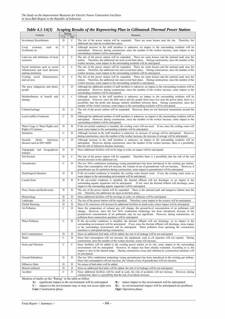
The Study on the Improvement Measures for Electric Power Generation Facilities in Java-Bali Region in the Republic of Indonesia
Table 4.1-14(3) Scoping Results of the Repowering Plan in Gilimanuk Thermal Power Station Rating Criteria Con Ope Reasons
Involuntary Resettlement D C The site of the power station will be expanded. There are some houses near the site. Therefore, the additional site must be avoided their place.
Local economy such as livelihood, etc.
C D Although increase in the staff members is unknown, no impact to the surrounding residents will be anticipated. However, during construction, since the number of the worker increase, some impact to the surrounding residents will be anticipated.
Land use and utilization of local resources
C C The site of the power station will be expanded. There are some houses and the national park near the station. Therefore, the additional site must avoid their place. During construction, since the number of the worker increase, some impact to the surrounding residents will be anticipated.
Social institution such as social infrastructure and local decision making institution
C C The site of the power station will be expanded. There are some houses and the national park near the station. Therefore, the additional site must avoid their place. During construction, since the number of the worker increase, some impact to the surrounding residents will be anticipated.
Existing social infrastructures and services
C C The site of the power station will be expanded. There are some houses and the national park near the station. Therefore, the additional site must avoid their place. During construction, since the number of the worker increase, some impact to the surrounding residents is anticipated.
The poor, indigenous and ethnic people
C D Although the additional number of staff members is unknown, no impact to the surrounding residents will be anticipated. However, during construction, since the number of the worker increase, some impact to the surrounding residents will be anticipated.
Misdistribution of benefit and damage
C C Although increase in the staff members is unknown, no impact to the surrounding residents will be anticipated. However, since the Bali native and the people from Jawa live near the power plant, there is a possibility that the profit and damage unfairly distribute between them. During construction, since the number of the worker increase, some impact to the surrounding residents will be anticipated.
Cultural heritage D D The site of the power station will be expanded. However, there are not historical monuments around the site.
Local conflict of interests C D Although the additional number of staff members is unknown, no impact to the surrounding residents will be anticipated. However, during construction, since the number of the worker increase, some impact to the surrounding residents will be anticipated.
Water Usage or Water Rights and Rights of Common
D B If the air-cooled condenser is installed, the cooling water will not need. If not, since the cooling water will need, some impact to the surrounding residents will be anticipated.
Sanitation C D Although increase in the staff members is unknown, no increase of sewage will be anticipated. However, during construction, since the number of the worker increase, the increase of sewage will be anticipated.
Hazards (Risk) Infectious diseases such as HIV/AIDS
C D Although increase in the staff members is unknown, no impact to the surrounding residents will be anticipated. However, during construction, since the number of the worker increase, there is a possibility that the risk of infectious diseases increases.
Topography and Geographical features
D D Since additional facilities will not be large in scale, no impact will be anticipated.
Soil Erosion D C The site of the power station will be expanded. Therefore there is a possibility that the risk of the soil erosion increase in the additional site.
Groundwater C D The low NOx combustion technology (using groundwater) has been introduced in the existing gas turbine. Since fuel consumption will not increase, the volume of use of groundwater will not increase. However, if groundwater use for sanitation during construction, some impact to groundwater will be anticipated
Hydrological Situation D B
If the air-cooled condenser is installed, the cooling water doesn't need. If not, the cooling water need, so some impact to the surrounding environment will be anticipated.
Coastal Zone D B
If the air-cooled condenser is installed, the thermal effluent will not discharge, so no impact to the surrounding aquatic organisms will be anticipated. If not, since the thermal effluent will discharge, some impact to the surrounding aquatic organisms will be anticipated.
Flora, Fauna and Biodiversity D B The site of the power station will be expanded. There is the national park and mangrove habitat near the site. Therefore, the additional site must avoid their place.
Meteorology D D Since additional facilities will be not large in scale, no influence will be anticipated. Landscape D C The site of the power station will be expanded. Therefore, some impact to the scenery will be anticipated. Global Warming D D Since CO2 emissions will increase by additional facilities in small scale, minor impact will be anticipated. Air Pollution C D Since the temperature of exhaust gas will change, the ground-level concentration of air pollutants will
change. However, since the low NOx combustion technology has been introduced, increase of the ground-level concentration of air pollutants may be not significant. However, during construction, air pollution from construction machines will be anticipated.
Water Pollution C B If the air-cooled condenser is installed, the thermal effluent will not discharge, so no impact to the surrounding environment will be anticipated. If not, since the thermal effluent will discharge, some impact to the surrounding environment will be anticipated. Water pollution from operating the construction machines is anticipated during construction.
Soil Contamination D D Since no additional fuel tanks will be added, the risk of oil leakage will be not anticipated. Waste C D Since fuel consumption will not increase, the equipment, such as oil separator will not expand. During
construction, since the number of the worker increase, waste will increase. Noise and Vibration C C Since facilities will be added to the existing power station on its site, some impact to the surrounding
environment will be anticipated. However, its impact has been already evaluated. According to it, the impact is only in the limited range. During construction, noise and vibration by construction machines will be anticipated.
Ground Subsidence D D The low NOx combustion technology (using groundwater) has been introduced in the existing gas turbine. Since fuel consumption will not increase, the volume of use of groundwater will not increase.
Offensive Odor D D No source of bad odors will be added. Bottom sediment D D Since no additional fuel tanks will be added, the risk of oil leakage will be not anticipated. Accident C D Since additional facilities will be small in scale, the risk of accidents will not increase. However, during
construction, there is a possibility that the risk of accidents increase. Mention of marks on the “Rating” in the table as follow
A : significant impact to the environment will be anticipated B ; minor impact to the environment will be anticipated C : impact to the environment may or may not occur right now D ; no environmental impact will be anticipated (no problem) Con: Construction phase Ope: Operation phase
Final Report < Summary > - 64 -
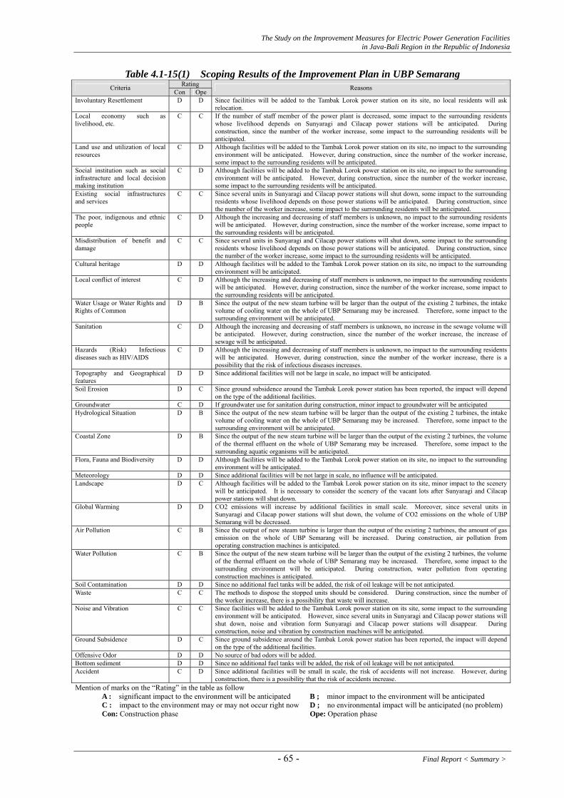
The Study on the Improvement Measures for Electric Power Generation Facilities in Java-Bali Region in the Republic of Indonesia
Table 4.1-15(1) Scoping Results of the Improvement Plan in UBP Semarang Rating Criteria Con Ope Reasons
Involuntary Resettlement D D Since facilities will be added to the Tambak Lorok power station on its site, no local residents will ask relocation.
Local economy such as livelihood, etc.
C C If the number of staff member of the power plant is decreased, some impact to the surrounding residents whose livelihood depends on Sunyaragi and Cilacap power stations will be anticipated. During construction, since the number of the worker increase, some impact to the surrounding residents will be anticipated.
Land use and utilization of local resources
C D Although facilities will be added to the Tambak Lorok power station on its site, no impact to the surrounding environment will be anticipated. However, during construction, since the number of the worker increase, some impact to the surrounding residents will be anticipated.
Social institution such as social infrastructure and local decision making institution
C D Although facilities will be added to the Tambak Lorok power station on its site, no impact to the surrounding environment will be anticipated. However, during construction, since the number of the worker increase, some impact to the surrounding residents will be anticipated.
Existing social infrastructures and services
C C Since several units in Sunyaragi and Cilacap power stations will shut down, some impact to the surrounding residents whose livelihood depends on those power stations will be anticipated. During construction, since the number of the worker increase, some impact to the surrounding residents will be anticipated.
The poor, indigenous and ethnic people
C D Although the increasing and decreasing of staff members is unknown, no impact to the surrounding residents will be anticipated. However, during construction, since the number of the worker increase, some impact to the surrounding residents will be anticipated.
Misdistribution of benefit and damage
C C Since several units in Sunyaragi and Cilacap power stations will shut down, some impact to the surrounding residents whose livelihood depends on those power stations will be anticipated. During construction, since the number of the worker increase, some impact to the surrounding residents will be anticipated.
Cultural heritage D D Although facilities will be added to the Tambak Lorok power station on its site, no impact to the surrounding environment will be anticipated.
Local conflict of interest C D Although the increasing and decreasing of staff members is unknown, no impact to the surrounding residents will be anticipated. However, during construction, since the number of the worker increase, some impact to the surrounding residents will be anticipated.
Water Usage or Water Rights and Rights of Common
D B Since the output of the new steam turbine will be larger than the output of the existing 2 turbines, the intake volume of cooling water on the whole of UBP Semarang may be increased. Therefore, some impact to the surrounding environment will be anticipated.
Sanitation C D Although the increasing and decreasing of staff members is unknown, no increase in the sewage volume will be anticipated. However, during construction, since the number of the worker increase, the increase of sewage will be anticipated.
Hazards (Risk) Infectious diseases such as HIV/AIDS
C D Although the increasing and decreasing of staff members is unknown, no impact to the surrounding residents will be anticipated. However, during construction, since the number of the worker increase, there is a possibility that the risk of infectious diseases increases.
Topography and Geographical features
D D Since additional facilities will not be large in scale, no impact will be anticipated.
Soil Erosion D C Since ground subsidence around the Tambak Lorok power station has been reported, the impact will depend on the type of the additional facilities.
Groundwater C D If groundwater use for sanitation during construction, minor impact to groundwater will be anticipated Hydrological Situation D B Since the output of the new steam turbine will be larger than the output of the existing 2 turbines, the intake
volume of cooling water on the whole of UBP Semarang may be increased. Therefore, some impact to the surrounding environment will be anticipated.
Coastal Zone D B Since the output of the new steam turbine will be larger than the output of the existing 2 turbines, the volume of the thermal effluent on the whole of UBP Semarang may be increased. Therefore, some impact to the surrounding aquatic organisms will be anticipated.
Flora, Fauna and Biodiversity D D Although facilities will be added to the Tambak Lorok power station on its site, no impact to the surrounding environment will be anticipated.
Meteorology D D Since additional facilities will be not large in scale, no influence will be anticipated. Landscape D C Although facilities will be added to the Tambak Lorok power station on its site, minor impact to the scenery
will be anticipated. It is necessary to consider the scenery of the vacant lots after Sunyaragi and Cilacap power stations will shut down.
Global Warming D D CO2 emissions will increase by additional facilities in small scale. Moreover, since several units in Sunyaragi and Cilacap power stations will shut down, the volume of CO2 emissions on the whole of UBP Semarang will be decreased.
Air Pollution C B Since the output of new steam turbine is larger than the output of the existing 2 turbines, the amount of gas emission on the whole of UBP Semarang will be increased. During construction, air pollution from operating construction machines is anticipated.
Water Pollution C B Since the output of the new steam turbine will be larger than the output of the existing 2 turbines, the volume of the thermal effluent on the whole of UBP Semarang may be increased. Therefore, some impact to the surrounding environment will be anticipated. During construction, water pollution from operating construction machines is anticipated.
Soil Contamination D D Since no additional fuel tanks will be added, the risk of oil leakage will be not anticipated. Waste C C The methods to dispose the stopped units should be considered. During construction, since the number of
the worker increase, there is a possibility that waste will increase. Noise and Vibration C C Since facilities will be added to the Tambak Lorok power station on its site, some impact to the surrounding
environment will be anticipated. However, since several units in Sunyaragi and Cilacap power stations will shut down, noise and vibration form Sunyaragi and Cilacap power stations will disappear. During construction, noise and vibration by construction machines will be anticipated.
Ground Subsidence D C Since ground subsidence around the Tambak Lorok power station has been reported, the impact will depend on the type of the additional facilities.
Offensive Odor D D No source of bad odors will be added. Bottom sediment D D Since no additional fuel tanks will be added, the risk of oil leakage will be not anticipated. Accident C D Since additional facilities will be small in scale, the risk of accidents will not increase. However, during
construction, there is a possibility that the risk of accidents increase. Mention of marks on the “Rating” in the table as follow
A : significant impact to the environment will be anticipated B ; minor impact to the environment will be anticipated C : impact to the environment may or may not occur right now D ; no environmental impact will be anticipated (no problem) Con: Construction phase Ope: Operation phase
- 65 - Final Report < Summary >

The Study on the Improvement Measures for Electric Power Generation Facilities in Java-Bali Region in the Republic of Indonesia
Table 4.1-15(2) Scoping Results of the Improvement Plan in UBP Perak Grati Rating Criteria Con Ope Reasons
Involuntary Resettlement D D Since facilities will be added to the Grati power station on its site, no local residents will ask relocation. Local economy such as livelihood, etc.
C C If the number of staff member of the power plant is decreased, some impact to the surrounding residents whose livelihood depends on Perak power station will be anticipated. During construction, since the number of the worker increase, some impact to the surrounding residents will be anticipated.
Land use and utilization of local resources
C D Although facilities will be added to the Grati power station on its site, no impact to the surrounding environment will be anticipated. However, during construction, since the number of the worker increase, some impact to the surrounding residents will be anticipated.
Social institution such as social infrastructure and local decision making institution
C D Although facilities will be added to the Grati power station on its site, no impact to the surrounding environment will be anticipated. However, during construction, since the number of the worker increase, some impact to the surrounding residents will be anticipated.
Existing social infrastructures and services
C C Since several units in Perak power station will shut down, some impact to the surrounding residents whose livelihood depends on Perak power station will be anticipated. During construction, since the number of the worker increase, some impact to the surrounding residents will be anticipated.
The poor, indigenous and ethnic people
C D Although the increasing and decreasing of staff members is unknown, no impact to the surrounding residents will be anticipated. However, during construction, since the number of the worker increase, some impact to the surrounding residents will be anticipated.
Misdistribution of benefit and damage
C C Since several units in Perak power station will shut down, some impact to the surrounding residents whose livelihood depends on Perak power station will be anticipated. However, during construction, since the number of the worker increase, some impact to the surrounding residents will be anticipated.
Cultural heritage D D Although facilities will be added to the Grati power station on its site, no impact to the surrounding environment will be anticipated.
Local conflict of interest C D Although the increasing and decreasing of staff members is unknown, no impact to the surrounding residents will be anticipated. However, during construction, since the surrounding residents are conservative, there is a possibility that conflict between the residents and the workers happens.
Water Usage or Water Rights and Rights of Common
D D Even if the intake volume of cooling water on the whole of UBP Perak Grati increase, the impact has been already evaluated. According to it, the impact is only in the limited range.
Sanitation C D Although the increasing and decreasing of staff members is unknown, no increase in the sewage volume will be anticipated. However, during construction, since the number of the worker increase, the increase of sewage will be anticipated.
Hazards (Risk) Infectious diseases such as HIV/AIDS
C D Although the increasing and decreasing of staff members is unknown, no impact to the surrounding residents will be anticipated. However, during construction, since the number of the worker increase, there is a possibility that the risk of infectious diseases increases.
Topography and Geographical features
D D Since additional facilities will not be large in scale, no impact will be anticipated.
Soil Erosion D D Although facilities will be added to the Grati power station on its site, no impact will be anticipated. Groundwater C D If groundwater use for sanitation during construction, minor impact to groundwater will be anticipated Hydrological Situation D D Even if the intake volume of cooling water on the whole of UBP Perak Grati increase, the impact has been
already evaluated. According to it, the impact is only in the limited range. Coastal Zone D D Even if the volume of the thermal effluent on the whole of UBP Perak Grati increase, the impact has been
already evaluated. According to it, the impact is only in the limited range. Flora, Fauna and Biodiversity D D Although facilities will be added to the existing power station on its site, no impact to the surrounding
environment will be anticipated. Meteorology D D Since additional facilities will be not large in scale, no influence will be anticipated. Landscape D C Although facilities will be added to the Grati power station on its site, minor impact to the scenery will be
anticipated. It is necessary to consider the scenery of the vacant lots after Perak power station will shut down.
Global Warming D D Since fuel consumption in Grati power station is not increased, the amount of CO2 emission is not increased. Moreover, since several units in Perak power station will shut down, the volume of CO2 emissions on the whole of UBP Perak Grati will be decreased.
Air Pollution C D Since fuel consumption will not increase, the value of air pollutants will not increase. Moreover, since several units in Perak power station will shut down, the value of air pollutants on the whole of UBP Perak Grati will be decreased. However, during construction, air pollution by construction machines will be anticipated.
Water Pollution C D Even if the volume of the thermal effluent on the whole of UBP Perak Grati increase, the impact has been already evaluated. According to it, the impact is only in the limited range. However, during construction, water pollution from operating construction machines will be anticipated.
Soil Contamination D D Since no additional fuel tanks will be added, the risk of oil leakage will be not anticipated. Waste C C The methods to dispose the stopped units should be considered. During construction, since the number of
the worker increase, there is a possibility that waste will increase. Noise and Vibration C C Since facilities will be added to the Grati power station on its site, some impact to the surrounding
environment will be anticipated. However, since several units in Perak power station will shut down, noise and vibration form Perak power station will disappear. During construction, noise and vibration by construction machines will be anticipated.
Ground Subsidence D D Since additional facilities will be small in scale, no impact will be anticipated. Offensive Odor D D No source of bad odors will be added. Bottom sediment D D Since no additional fuel tanks will be added, the risk of oil leakage will be not anticipated. Accident C D Since additional facilities will be small in scale, the risk of accidents will not increase. However, during
construction, there is a possibility that the risk of accidents increase. Mention of marks on the “Rating” in the table as follow
A : significant impact to the environment will be anticipated B ; minor impact to the environment will be anticipated C : impact to the environment may or may not occur right now D ; no environmental impact will be anticipated (no problem) Con: Construction phase Ope: Operation phase
Final Report < Summary > - 66 -

The Study on the Improvement Measures for Electric Power Generation Facilities in Java-Bali Region in the Republic of Indonesia
Table 4.1-15(3) Scoping Results of the Improvement Plan in UBP Bali Rating Criteria
Con Ope Reasons
Involuntary Resettlement D C The site of the Gilimanuk power station will be expanded. There are some houses near the site. Therefore, the additional site must be avoided the place.
Local economy such as livelihood, etc.
C C Since Pesanggaran power plant will shut down, the impact to the surrounding residents whose livelihood depends on Pesanggaran power station will be anticipated. During construction, since the number of the worker increase, some impact to the surrounding residents will be anticipated.
Land use and utilization of local resources
C C The site of the Gilimanuk power station will be expanded. There are some houses and the national park near the site. Therefore, the additional site must be avoided their place. During construction, since the number of the worker increase, some impact to the surrounding residents will be anticipated.
Social institution such as social infrastructure and local decision making institution
C C The site of the Gilimanuk power station will be expanded. There are some houses and the national park near the site. Therefore, the additional site must be avoided their place. During construction, since the number of the worker increase, some impact to the surrounding residents will be anticipated.
Existing social infrastructures and services
C C The site of the Gilimanuk power station will be expanded. There are some houses and the national park near the site. Therefore, the additional site must be avoided their place. Since Pesanggaran power plant will shut down, the impact to the surrounding residents whose livelihood depends on Pesanggaran power station will be anticipated. During construction, since the number of the worker increase, some impact to the surrounding residents will be anticipated.
The poor, indigenous and ethnic people
C D Although the increasing and decreasing of staff members is unknown no impact to the surrounding residents will be anticipated. However, during construction, since the number of the worker increase, some impact to the surrounding residents will be anticipated.
Misdistribution of benefit and damage
C C Although the increasing and decreasing of staff members is unknown no impact to the surrounding residents will be anticipated. However, since the Bali native and the people from Jawa live near the power plant, there is a possibility that the profit and damage unfairly distribute between them.Moreover, since Pesanggaran power plant will shut down, the impact to the surrounding residents whose livelihood depends on Pesanggaran power station will be anticipated. During construction, since the number of the worker increase, some impact to the surrounding residents will be anticipated.
Cultural heritage D D The site of the Gilimanuk power station will be expanded. However, there are not historical monuments around the site.
Local conflict of interests C D Although the increasing and decreasing of staff members is unknown, no impact to the surrounding residents will be anticipated. However, during construction, since the number of the worker increase, some impact to the surrounding residents will be anticipated.
Water Usage or Water Rights and Rights of Common
D B As for the Gilimanuk power station, if the air-cooled condenser is installed, the cooling water will not need. If not, since the cooling water will need, some impact to the surrounding residents will be anticipated.
Sanitation C D Although the increasing and decreasing of staff members is unknown, no increase of sewage will be anticipated. However, during construction, since the number of the worker increase, the increase of sewage will be anticipated.
Hazards (Risk) Infectious diseases such as HIV/AIDS
C D Although the increasing and decreasing of staff members is unknown, no impact to the surrounding residents will be anticipated. However, during construction, since the number of the worker increase, there is a possibility that the risk of infectious diseases increases.
Topography and Geographical features
D D Since additional facilities will not be large in scale, no impact will be anticipated.
Soil Erosion D C The site of the Gilimanuk power station will be expanded. Therefore there is a possibility that the risk of the soil erosion increase in the additional site.
Groundwater C D As for the Gilimanuk power station, the low NOx combustion technology (using groundwater) has been introduced in the existing gas turbine. Since fuel consumption will not increase, the volume of use of groundwater will not increase. However, if groundwater use for sanitation during construction, some impact to groundwater will be anticipated
Hydrological Situation D B As for the Gilimanuk power station, if the air-cooled condenser is installed, the cooling water doesn't need. If not, the cooling water need, so some impact to the surrounding environment will be anticipated.
Coastal Zone D B As for the Gilimanuk power station, if the air-cooled condenser is installed, the thermal effluent will not discharge, so no impact to the surrounding aquatic organisms will be anticipated. If not, since the thermal effluent will discharge, some impact to the surrounding aquatic organisms will be anticipated.
Flora, Fauna and Biodiversity D B
The site of the Gilimanuk power station will be expanded. There is the national park and mangrove habitat near the site. Therefore, the additional site must avoid their place.
Meteorology D D Since additional facilities will be not large in scale, no influence will be anticipated. Landscape D C The site of the Gilimanuk power station will be expanded. Therefore, some impact to the scenery
will be anticipated. It is necessary to consider the scenery of the vacant lots after Pesanggaran power station will shut down.
Global Warming D D CO2 emissions will increase by additional facilities in small scale. Moreover, since several units in Pesanggaran power station will shut down, the volume of CO2 emissions on the whole of UBP Bali will be decreased.
Air Pollution C D As for the Gilimanuk power station, since the temperature of exhaust gas will change, the ground-level concentration of air pollutants will change. However, since the low NOx combustion technology has been introduced, increase of the ground-level concentration of air pollutants may be not significant. Moreover, since several units in Pesanggaran power station will shut down, air pollutants by Pesanggaran power station will disappear. However, during construction, air pollution from construction machines will be anticipated.
- 67 - Final Report < Summary >
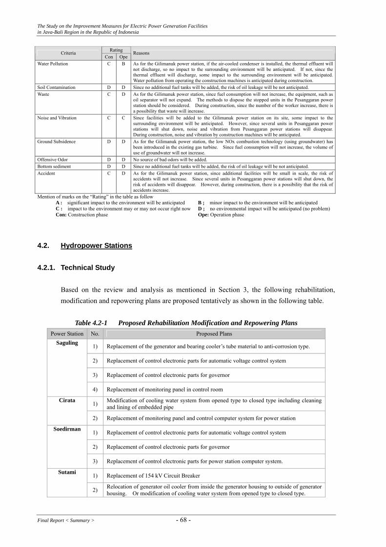
The Study on the Improvement Measures for Electric Power Generation Facilities in Java-Bali Region in the Republic of Indonesia
Rating Criteria Con Ope
Reasons
Water Pollution C B As for the Gilimanuk power station, if the air-cooled condenser is installed, the thermal effluent will not discharge, so no impact to the surrounding environment will be anticipated. If not, since the thermal effluent will discharge, some impact to the surrounding environment will be anticipated.Water pollution from operating the construction machines is anticipated during construction.
Soil Contamination D D Since no additional fuel tanks will be added, the risk of oil leakage will be not anticipated. Waste C D As for the Gilimanuk power station, since fuel consumption will not increase, the equipment, such as
oil separator will not expand. The methods to dispose the stopped units in the Pesanggaran power station should be considered. During construction, since the number of the worker increase, there is a possibility that waste will increase.
Noise and Vibration C C Since facilities will be added to the Gilimanuk power station on its site, some impact to the surrounding environment will be anticipated. However, since several units in Pesanggaran power stations will shut down, noise and vibration from Pesanggaran power stations will disappear.During construction, noise and vibration by construction machines will be anticipated.
Ground Subsidence D D As for the Gilimanuk power station, the low NOx combustion technology (using groundwater) has been introduced in the existing gas turbine. Since fuel consumption will not increase, the volume of use of groundwater will not increase.
Offensive Odor D D No source of bad odors will be added. Bottom sediment D D Since no additional fuel tanks will be added, the risk of oil leakage will be not anticipated. Accident C D As for the Gilimanuk power station, since additional facilities will be small in scale, the risk of
accidents will not increase. Since several units in Pesanggaran power stations will shut down, the risk of accidents will disappear. However, during construction, there is a possibility that the risk of accidents increase.
Mention of marks on the “Rating” in the table as follow A : significant impact to the environment will be anticipated B ; minor impact to the environment will be anticipated C : impact to the environment may or may not occur right now D ; no environmental impact will be anticipated (no problem) Con: Construction phase Ope: Operation phase
4.2. Hydropower Stations
4.2.1. Technical Study
Based on the review and analysis as mentioned in Section 3, the following rehabilitation, modification and repowering plans are proposed tentatively as shown in the following table.
Table 4.2-1 Proposed Rehabilitation Modification and Repowering Plans
Power Station No. Proposed Plans
1) Replacement of the generator and bearing cooler’s tube material to anti-corrosion type.
2) Replacement of control electronic parts for automatic voltage control system
3) Replacement of control electronic parts for governor
Saguling
4) Replacement of monitoring panel in control room
1) Modification of cooling water system from opened type to closed type including cleaning and lining of embedded pipe
Cirata
2) Replacement of monitoring panel and control computer system for power station
1) Replacement of control electronic parts for automatic voltage control system
2) Replacement of control electronic parts for governor
Soedirman
3) Replacement of control electronic parts for power station computer system.
1) Replacement of 154 kV Circuit Breaker Sutami
2) Relocation of generator oil cooler from inside the generator housing to outside of generator housing. Or modification of cooling water system from opened type to closed type.
Final Report < Summary > - 68 -

The Study on the Improvement Measures for Electric Power Generation Facilities in Java-Bali Region in the Republic of Indonesia
4.2.2. Economic Financial Analysis
Rehabilitation/modification and repowering plans relating to the existing hydropower stations proposed by the JICA Study Team are rehabilitation/modification plans only as mentioned in Section 4.2.1. The main purpose of rehabilitation/modification plan is to improve the reliability of operation, in other words, to reduce the forced outage caused or might be caused by deterioration and /or defect of power generation facilities. However, from the economic and financial viewpoint, it is very difficult to estimate the benefit (improvement of reliability) in money term because the extent to which the improvement of reliability will be achieved by rehabilitation/modification plans is unforeseeable. Based on the above reason, the utilization of JBIC export credit for rehabilitation/ modification plans is proposed here as mentioned in Section 2.5 instead of economic and financial analyses. In the meeting with JBIC Jakarta Office on June 7, 2006, the JBIC informed of the following assistance policy for the future in Indonesia.
a) Development of PLTP (Geothermal Power Station) b) Development and reinforcement of Transmission Line in outer islands c) Promotion of rehabilitation/modification and repowering plans for the existing power
stations in Java-Bali region
4.2.3. Environmental and Social Consideration
Rehabilitation/modification and repowering plans relating to existing hydropower stations proposed by the Study Team are shown in Section 4.2.1. As shown in Section 4.2.1, no repowering plan is proposed. Rehabilitation/modification plans including replacement of facilities are not required AMDAL because the relevant engineering woks are envisaged to be small-scale and not to affect the serious impact on the environmental aspects. And there seems to be no environmental and social consideration issue relating to improvement measures for operation and maintenance for the existing hydropower stations as well as thermal power stations.
- 69 - Final Report < Summary >
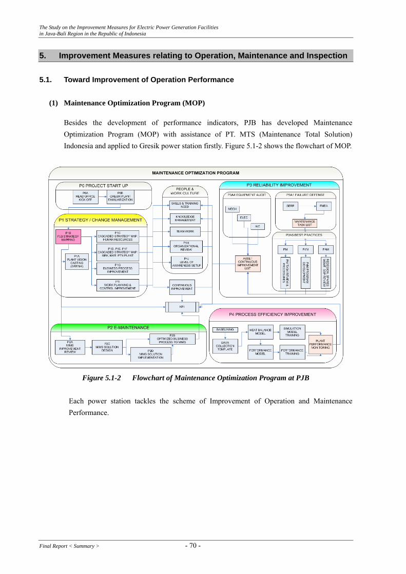
The Study on the Improvement Measures for Electric Power Generation Facilities in Java-Bali Region in the Republic of Indonesia
5. Improvement Measures relating to Operation, Maintenance and Inspection 5.1. Toward Improvement of Operation Performance
(1) Maintenance Optimization Program (MOP)
Besides the development of performance indicators, PJB has developed Maintenance Optimization Program (MOP) with assistance of PT. MTS (Maintenance Total Solution) Indonesia and applied to Gresik power station firstly. Figure 5.1-2 shows the flowchart of MOP.
Figure 5.1-2 Flowchart of Maintenance Optimization Program at PJB
Each power station tackles the scheme of Improvement of Operation and Maintenance Performance.
Final Report < Summary > - 70 -
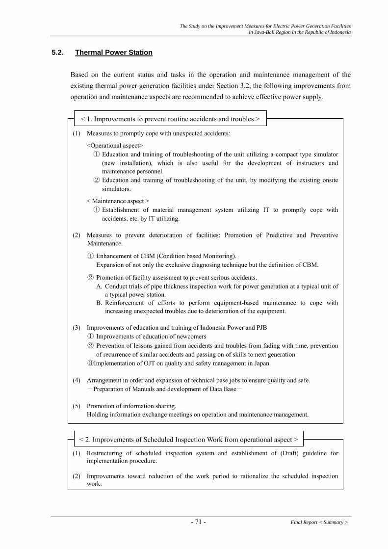
The Study on the Improvement Measures for Electric Power Generation Facilities in Java-Bali Region in the Republic of Indonesia
5.2. Thermal Power Station
Based on the current status and tasks in the operation and maintenance management of the existing thermal power generation facilities under Section 3.2, the following improvements from operation and maintenance aspects are recommended to achieve effective power supply.
(1) Measures to promptly cope with unexpected accidents:
<Operational aspect> ① Education and training of troubleshooting of the unit utilizing a compact type simulator
(new installation), which is also useful for the development of instructors and maintenance personnel.
② Education and training of troubleshooting of the unit, by modifying the existing onsite simulators.
< Maintenance aspect > ① Establishment of material management system utilizing IT to promptly cope with
accidents, etc. by IT utilizing. (2) Measures to prevent deterioration of facilities: Promotion of Predictive and Preventive
Maintenance.
① Enhancement of CBM (Condition based Monitoring). Expansion of not only the exclusive diagnosing technique but the definition of CBM.
② Promotion of facility assessment to prevent serious accidents. A. Conduct trials of pipe thickness inspection work for power generation at a typical unit of
a typical power station. B. Reinforcement of efforts to perform equipment-based maintenance to cope with
increasing unexpected troubles due to deterioration of the equipment. (3) Improvements of education and training of Indonesia Power and PJB
① Improvements of education of newcomers ② Prevention of lessons gained from accidents and troubles from fading with time, prevention
of recurrence of similar accidents and passing on of skills to next generation ③Implementation of OJT on quality and safety management in Japan
(4) Arrangement in order and expansion of technical base jobs to ensure quality and safe. -Preparation of Manuals and development of Data Base- (5) Promotion of information sharing. Holding information exchange meetings on operation and maintenance management.
< 1. Improvements to prevent routine accidents and troubles >
(2) Improvements toward reduction of the work period to rationalize the scheduled inspection work.
< 2. Improvements of Scheduled Inspection Work from operational aspect >
(1) Restructuring of scheduled inspection system and establishment of (Draft) guideline for implementation procedure.
- 71 - Final Report < Summary >
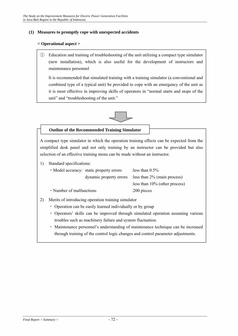
The Study on the Improvement Measures for Electric Power Generation Facilities in Java-Bali Region in the Republic of Indonesia
(1) Measures to promptly cope with unexpected accidents
< Operational aspect >
①
Education and training of troubleshooting of the unit utilizing a compact type simulator (new installation), which is also useful for the development of instructors and maintenance personnel
It is recommended that simulated training with a training simulator (a conventional and combined type of a typical unit) be provided to cope with an emergency of the unit as it is most effective in improving skills of operators in “normal starts and stops of the unit” and “troubleshooting of the unit.”
Asim
2)
compact type simulator in which the operation training effects can be expected from the plified desk panel and not only training by an instructor can be provided but also
selection of an effective training menu can be made without an instructor.
1) Standard specifications: ・Model accuracy: static property errors :less than 0.5% dynamic property errors :less than 2% (main process) :less than 10% (other process) ・Number of malfunctions :200 pieces
Merits of introducing operation training simulator ・ Operation can be easily learned individually or by group ・ Operators’ skills can be improved through simulated operation assuming various
troubles such as machinery failure and system fluctuation. ・ Maintenance personnel’s understanding of maintenance technique can be increased
through training of the control logic changes and control parameter adjustments.
Outline of the Recommended Training Simulator
Final Report < Summary > - 72 -

The Study on the Improvement Measures for Electric Power Generation Facilities in Java-Bali Region in the Republic of Indonesia
Simulation Training Course: Learning of Knowledge & Technique in Standard Target of 5 Years
・Advanced course : Learning of exact troubleshooting for unexpectedly occurring accidents and troubles of facilities.
・Middle class course : Learning of exact troubleshooting for frequently occurring accidents and troubles of facilities.
・Beginners’ course : Learning of start-up/Shutdown of normal units. Learning of easy troubleshooting.
Image of Upgrading of High School Graduates
Standard Target: 5 yrs
Step I, II
Simulator Training Course
OJT Step Up
Beginners’ Course
Middle Class Course
Pre-Advanced Course
Advanced Course
Basic Education 3 yrs Applied Education (2-4 yrs)
Step I, II, III
Step IV, V
Control
Patrol
Control
Step I, IV : Learning of knowledge at Power Station … to be checked by paper testsStep II : Learning of skills … to be checked by simulated operation tests Step III, V : Learning of skills which are common
- 73 - Final Report < Summary >
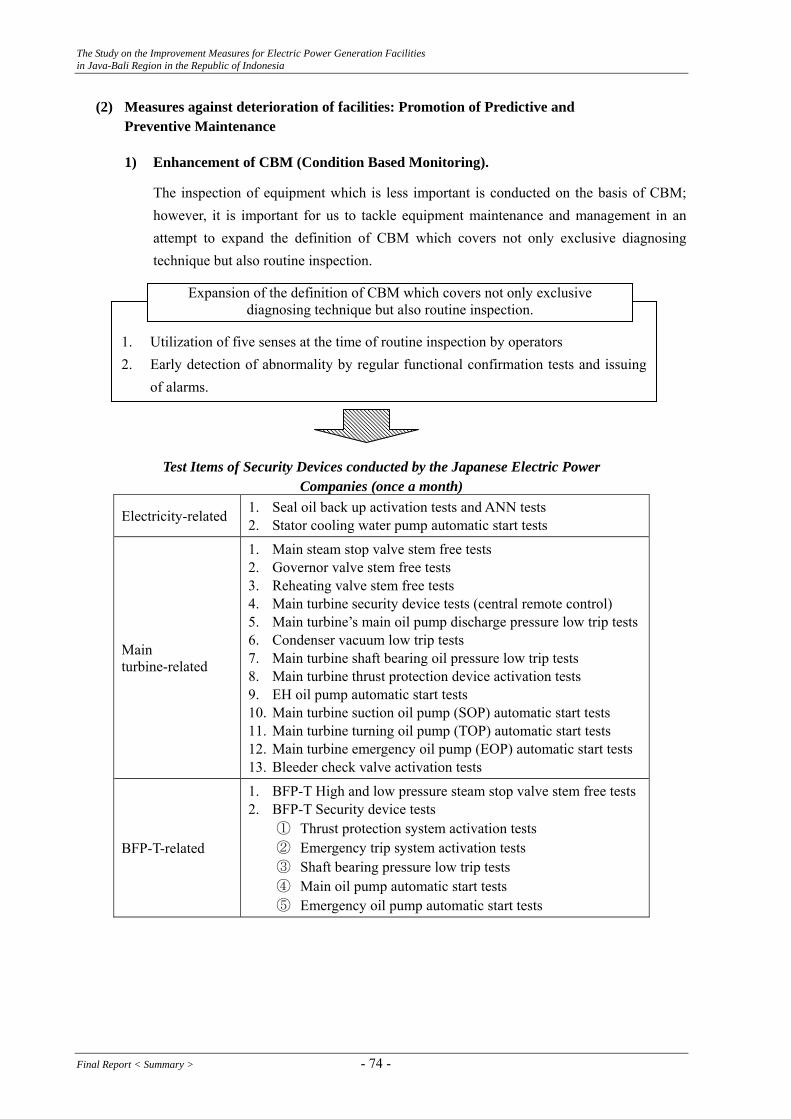
The Study on the Improvement Measures for Electric Power Generation Facilities in Java-Bali Region in the Republic of Indonesia
(2) Measures against deterioration of facilities: Promotion of Predictive and Preventive Maintenance
1) Enhancement of CBM (Condition Based Monitoring).
The inspection of equipment which is less important is conducted on the basis of CBM; however, it is important for us to tackle equipment maintenance and management in an attempt to expand the definition of CBM which covers not only exclusive diagnosing technique but also routine inspection.
1. 2.
Utilization of five senses at the time of routine inspection by operators Early detection of abnormality by regular functional confirmation tests and issuing of alarms.
Expansion of the definition of CBM which covers not only exclusive diagnosing technique but also routine inspection.
Test Items of Security Devices conducted by the Japanese Electric Power
Companies (once a month)
Electricity-related 1. Seal oil back up activation tests and ANN tests 2. Stator cooling water pump automatic start tests
Main turbine-related
1. Main steam stop valve stem free tests 2. Governor valve stem free tests 3. Reheating valve stem free tests 4. Main turbine security device tests (central remote control) 5. Main turbine’s main oil pump discharge pressure low trip tests 6. Condenser vacuum low trip tests 7. Main turbine shaft bearing oil pressure low trip tests 8. Main turbine thrust protection device activation tests 9. EH oil pump automatic start tests 10. Main turbine suction oil pump (SOP) automatic start tests 11. Main turbine turning oil pump (TOP) automatic start tests 12. Main turbine emergency oil pump (EOP) automatic start tests 13. Bleeder check valve activation tests
BFP-T-related
1. BFP-T High and low pressure steam stop valve stem free tests 2. BFP-T Security device tests
① Thrust protection system activation tests ② Emergency trip system activation tests ③ Shaft bearing pressure low trip tests ④ Main oil pump automatic start tests ⑤ Emergency oil pump automatic start tests
Final Report < Summary > - 74 -

The Study on the Improvement Measures for Electric Power Generation Facilities in Java-Bali Region in the Republic of Indonesia
2) Promotion of facility assessment to prevent serious accidents
a. Conduct trials of pipe thickness inspection work for power generation at a typical unit of a typical power station In August 2004, a pipeline breakage accident (a condenser pipe and a drain pipe of feed water heater) occurred due to reduction of pipe thickness caused by erosion and corrosion at two Japanese power stations, which resulted in a socially major problem. As a result of the pipeline thickness inspection at each power station of electric companies, IPP and private power stations soon after these accidents, many pipelines which did not meet TSR* (Thickness Shell Requirement) were found.
* “TSR” is the thickness required to maintain pipeline strength which is obtained by calculation.
IP and PJB are recommended to establish a pipeline management policy of thermal power facilities as well as pipeline inspection plans and conduct trials of the following contents at early stages in a typical unit of a typical power station because there seems to be the possibility of occurrence of the same accident in Indonesia as well as Japan.
1. Facilities subject to investigation: Thermal power generation facilities using steam turbines with output of 1 MW or more. 2. Pipelines subject to investigation: Pipelines made of materials which have a potential to suffer thickness reduction caused by
water and steam. Each pipeline of the following: ①Main steam system ②Reheat steam system ③Condenser system ④Feed water system ⑤Bleeder system ⑥Drain system 3. Portions subject to investigation (See Figure 5.2-1) : Portions which have a potential for thickness reduction due to erosion and corrosion. ①Control valve downstream ②Glove type check valve downstream ③Elbow ④T pipe ⑤Orifice downstream ⑥Swing type check valve downstream ⑦Reducer ⑧Bent pipe ⑨Glove type valve downstream 4. Inspection (test) method Inspection (test) method should be the following: ①Thickness measurement method with ultrasonic waves pulse reflection ②Test method by radioactive penetration image inspection ③Screening test method using pulse vortex ④Test method utilizing potential difference ⑤Test method with three-dimensional ultrasonic inspection 5. Inspection period: While the unit is shutdown during the scheduled inspection work period.
Contents of Inspection
- 75 - Final Report < Summary >

The Study on the Improvement Measures for Electric Power Generation Facilities in Java-Bali Region in the Republic of Indonesia
Figure 5.2-1 Measurement Points
Figure 5.2-2 Measurement Flow for Key Inspecting System
Decision standard thickness;
less than (tm)?
Preparation of skeleton of pipe thickness inspection range
Decision of measuring points by shape of the measuring parts
Conduct measurements at each measuring point
Yes Detailed measurement around the measuring points
(20mm pitch)
No
Evaluation of the Remaining Life
Pipe thickness evaluation at each measuring point
(Source: “Standard for thermal equipment for power generation”)
T : Pipe thickness tn : Minimum pipe thickness (Pipe thickness - Required
pipe thickness by calculation) tm : Decision standard thickness for detailed measurements tsr : Required pipe thickness by calculation
pipe thickness
T
(Negative difference)
tn
tm
Decision standard thickness for detailed measurement (tm) = Required pipe thickness by calculation +2/3 (minimum thickness - required pipe thickness by calculation) = tsr + 2/3 (tn-tsr)
tsr
2/3(tn-tsr)
Final Report < Summary > - 76 -

The Study on the Improvement Measures for Electric Power Generation Facilities in Java-Bali Region in the Republic of Indonesia
(3) Improvements of education and training at IP and PJB
① Prevention of lessons gained from accidents and troubles from fading with time, prevention of recurrence of similar accidents and passing on of skills to next
generation -Preparation of cases of troubles and entry of Data Base-
A. “A collection of unexpected or unusual trouble cases” - Min. 20 cases For example, ・A trip due to boiler “low drum level” ・Steam turbine trip while turbines are gaining speed ・Steam Adjusting Valve spring tightening bolts, etc. ・Inability to start units due to BCP trip while the units are being started up
B. “A collection of damage cases of equipment suffering aged deterioration” - Min. 20 cases
For example, ・Corrosion on exterior surface of pipeline ・Expansion damage (HRSG exhaust gas damper) ・Tube rupture due to surface corrosion ・System shutdown due to malfunction of sequencer, etc.
C. “A collection of facility trouble cases due to human errors” - Min. 20 cases For example, ・ Emergency shutdown of boilers due to erroneous operation of DCS (Digital
Control System) ・ Erroneous activation of Gland Steam Pressure Adjusting Valve due to erroneous
connection of the signal wires ・ Delay in startup due to failure of steam turbine startup conditions ・ Lowering of condenser vacuum
② Implementation of OJT on quality and safety control in Japan
Purpose : To acquire through OJT the actual status of quality and safetycontrol in scheduled inspection work of the Japanese electric powercompanies in order to enhance skills of maintenance personnel in quality and safety control and make horizontal development of suchskills in Indonesia.
Number of participants
: 4 to 5 persons (Supervisor class in charge of boilers, turbines, generators, instrumentation and electricity)
Implementing Place
: Existing coal-fired or gas-fired thermal power station and such a power station under construction
Duration : about 6 months × 2 times or so
- 77 - Final Report < Summary >
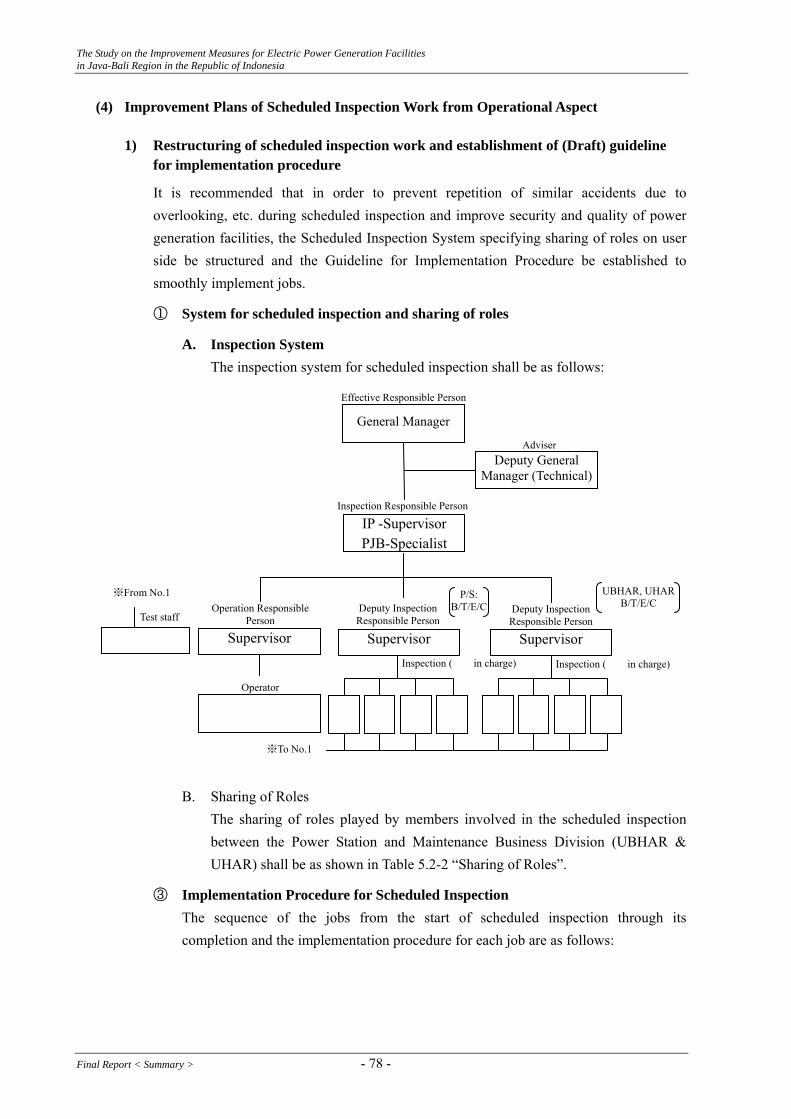
The Study on the Improvement Measures for Electric Power Generation Facilities in Java-Bali Region in the Republic of Indonesia
(4) Improvement Plans of Scheduled Inspection Work from Operational Aspect
1) Restructuring of scheduled inspection work and establishment of (Draft) guideline for implementation procedure
It is recommended that in order to prevent repetition of similar accidents due to overlooking, etc. during scheduled inspection and improve security and quality of power generation facilities, the Scheduled Inspection System specifying sharing of roles on user side be structured and the Guideline for Implementation Procedure be established to smoothly implement jobs.
① System for scheduled inspection and sharing of roles
A. Inspection System The inspection system for scheduled inspection shall be as follows:
Deputy Inspection Responsible Person
Effective Responsible Person
Deputy General Manager (Technical)
Adviser
General Manager
IP -Supervisor PJB-Specialist
Inspection Responsible Person
Supervisor
Deputy Inspection Responsible Person
Supervisor Supervisor
Operation Responsible Person
Operator
Inspection ( in charge) Inspection ( in charge)
※To No.1
From No.1
※
Test staff
P/S: B/T/E/C
UBHAR, UHARB/T/E/C
B. Sharing of Roles The sharing of roles played by members involved in the scheduled inspection
between the Power Station and Maintenance Business Division (UBHAR & UHAR) shall be as shown in Table 5.2-2 “Sharing of Roles”.
③ Implementation Procedure for Scheduled Inspection The sequence of the jobs from the start of scheduled inspection through its completion and the implementation procedure for each job are as follows:
Final Report < Summary > - 78 -
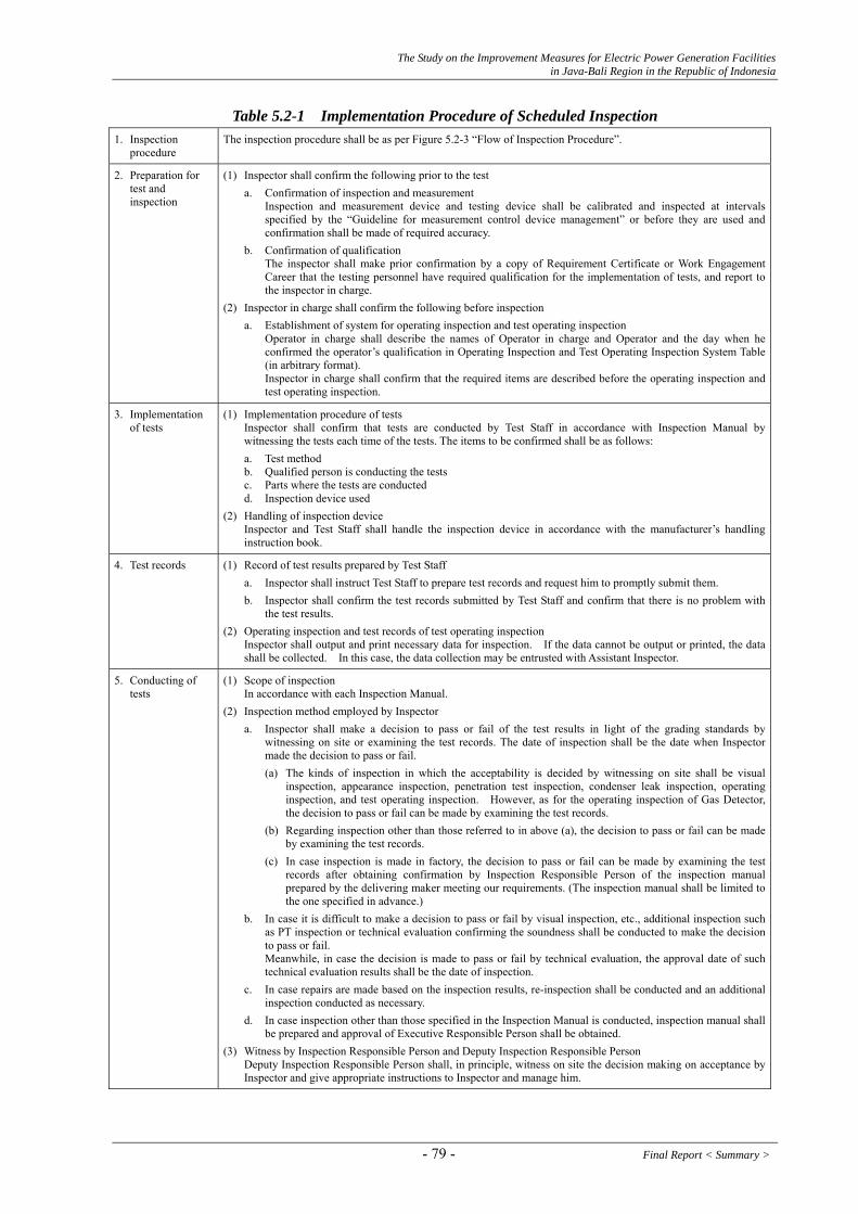
The Study on the Improvement Measures for Electric Power Generation Facilities in Java-Bali Region in the Republic of Indonesia
Table 5.2-1 Implementation Procedure of Scheduled Inspection 1. Inspection
procedure The inspection procedure shall be as per Figure 5.2-3 “Flow of Inspection Procedure”.
2. Preparation for test and inspection
(1) Inspector shall confirm the following prior to the test a. Confirmation of inspection and measurement
Inspection and measurement device and testing device shall be calibrated and inspected at intervals specified by the “Guideline for measurement control device management” or before they are used and confirmation shall be made of required accuracy.
b. Confirmation of qualification The inspector shall make prior confirmation by a copy of Requirement Certificate or Work Engagement Career that the testing personnel have required qualification for the implementation of tests, and report to the inspector in charge.
(2) Inspector in charge shall confirm the following before inspection a. Establishment of system for operating inspection and test operating inspection
Operator in charge shall describe the names of Operator in charge and Operator and the day when he confirmed the operator’s qualification in Operating Inspection and Test Operating Inspection System Table (in arbitrary format). Inspector in charge shall confirm that the required items are described before the operating inspection and test operating inspection.
3. Implementation of tests
(1) Implementation procedure of tests Inspector shall confirm that tests are conducted by Test Staff in accordance with Inspection Manual by witnessing the tests each time of the tests. The items to be confirmed shall be as follows:
a. Test method b. Qualified person is conducting the tests c. Parts where the tests are conducted d. Inspection device used
(2) Handling of inspection device Inspector and Test Staff shall handle the inspection device in accordance with the manufacturer’s handling instruction book.
4. Test records (1) Record of test results prepared by Test Staff a. Inspector shall instruct Test Staff to prepare test records and request him to promptly submit them. b. Inspector shall confirm the test records submitted by Test Staff and confirm that there is no problem with
the test results. (2) Operating inspection and test records of test operating inspection
Inspector shall output and print necessary data for inspection. If the data cannot be output or printed, the data shall be collected. In this case, the data collection may be entrusted with Assistant Inspector.
5. Conducting of tests
(1) Scope of inspection In accordance with each Inspection Manual.
(2) Inspection method employed by Inspector a. Inspector shall make a decision to pass or fail of the test results in light of the grading standards by
witnessing on site or examining the test records. The date of inspection shall be the date when Inspector made the decision to pass or fail. (a) The kinds of inspection in which the acceptability is decided by witnessing on site shall be visual
inspection, appearance inspection, penetration test inspection, condenser leak inspection, operating inspection, and test operating inspection. However, as for the operating inspection of Gas Detector, the decision to pass or fail can be made by examining the test records.
(b) Regarding inspection other than those referred to in above (a), the decision to pass or fail can be made by examining the test records.
(c) In case inspection is made in factory, the decision to pass or fail can be made by examining the test records after obtaining confirmation by Inspection Responsible Person of the inspection manual prepared by the delivering maker meeting our requirements. (The inspection manual shall be limited to the one specified in advance.)
b. In case it is difficult to make a decision to pass or fail by visual inspection, etc., additional inspection such as PT inspection or technical evaluation confirming the soundness shall be conducted to make the decision to pass or fail. Meanwhile, in case the decision is made to pass or fail by technical evaluation, the approval date of such technical evaluation results shall be the date of inspection.
c. In case repairs are made based on the inspection results, re-inspection shall be conducted and an additional inspection conducted as necessary.
d. In case inspection other than those specified in the Inspection Manual is conducted, inspection manual shall be prepared and approval of Executive Responsible Person shall be obtained.
(3) Witness by Inspection Responsible Person and Deputy Inspection Responsible Person Deputy Inspection Responsible Person shall, in principle, witness on site the decision making on acceptance by Inspector and give appropriate instructions to Inspector and manage him.
- 79 - Final Report < Summary >

The Study on the Improvement Measures for Electric Power Generation Facilities in Java-Bali Region in the Republic of Indonesia
6. Inspection records
(1) Recording of Inspection results a. Inspector shall use “Inspection records” to describe necessary matters and prepare inspection records.
Nothing shall be transcribed from the test records into the inspection records except minimum requirements. In case re-inspection is conducted or blank space of the inspection record format is insufficient due to additional inspection, inspection records shall be newly prepared. Each time inspection is conducted, the inspection results shall be confirmed by Deputy Inspection Responsible Person.
b. Deputy Inspection Responsible Person shall confirm that Inspector prepares appropriate records each time inspection is conducted and sign the inspection records. He shall also confirm completion of the inspection of all the facility items (name of inspection in the inspection records) and obtain approval of Inspection Responsible Person.
c. Inspection Responsible Person shall approve of the inspection records and conduct document registration and post in the scheduled inspection record data base inspection cover sheet, test records of operating inspection and test run inspection as well as inspection system table for operating inspection and test runs.
(2) Attachment to Inspection records a. Materials used to make a decision to pass or fail shall be attached to the inspection records. The original test
records prepared by the test staff shall be attached. b. Description or supplement of the inspection results shall be attached. c. As for operating inspection and test run inspection, the original of the test records and the actual records of
inspection system including Operation Responsible Person and Operator shall be attached. In case it is difficult to make a decision to pass or fail in light of the judgment standards, a list of the test records may be prepared. In that case, the original of the test records shall always be attached.
7. Measures against failure
If Inspector decides that any item does not meet the requirement, the most appropriate measures shall be studied and described in the intra-office prompt report and confirmation of Inspection Responsible Person shall be obtained. (1) In case repair is made
After gaining approval from Inspection Responsible Person, retest shall be conducted after the repair or replacement and the series of actions taken shall be recorded in the inspection records.
(2) In case repair is not made a. Technical evaluation
(a) If technical evaluation method is specified in the intra-office standards, technical evaluation shall be conducted in accordance with such standards.
(b) If there is no prescription in the intra-office standards, Inspection Responsible Person shall coordinate with the maker’s recommendations, operation records, etc, and if necessary, coordinate with the related parts and report to Executive Responsible Person on the result of the technical evaluation.
b. Special Employment If, as a result of the technical evaluation, Inspector decides that safe and stable operations can be continued until the next inspection, and Inspection Responsible Person approves of it, then it can be treated as Special Employment. The date when the special employment is approved shall be the date of inspection.
8. Delivery to next process
If Inspection Responsible Person approves as “pass” or as “Special employment” in making a decision to pass or fail, the delivery to the next process is permissible. If Deputy Inspection Responsible Person approves any item as “pass,” he is allowed to give permission to the assembly or restoration.
9. Inspection process management
Inspection Responsible Person shall prepare “Inspection Process Management Table” after receiving reports from Deputy Inspection Responsible Person and grasp each inspection process. After completion of the inspection, he shall make an interim report to Executive Responsible Person in general interlocking timing. (Such a report can be eliminated if the scheduled inspection does not include the general interlocking.) After making reports upon completion of the inspection, he shall post it on “Inspection Process Management Table” in Scheduled Inspection Record Data Base.”
10. Completion of scheduled inspection
When Inspection Responsible Person confirms the completion of all the scheduled inspections, the inspections shall be completed.
Final Report < Summary > - 80 -

The Study on the Improvement Measures for Electric Power Generation Facilities in Java-Bali Region in the Republic of Indonesia
Table 5.2-2 Sharing of Roles Title Contents of duty
Executive Responsible Person / General Manager of Power Station
He shall exercise control over jobs on security at the power station. If Deputy Superintendent is posted, he can have him assist his duty.
Inspection Responsible Person: Representatives of Maintenance Divisions at P/S IP: Supervisor Senior PJB: Specialist
・ He shall be responsible for appropriate implementation of scheduled inspections. ・ He shall prepare Inspection Manual and establish inspection system. ・ He shall post inspectors who have knowledge and experience required to conduct scheduled
inspections. On the basis that he shall be familiar and comply with the procedure necessary for inspection, he shall conduct inspection having sufficient contact and cooperation with parties concerned, and give appropriate instructions and make management of inspectors under his control performing their duty.
・ If there is any failure, he shall take measures in accordance with the guideline. ・ He shall confirm that there is no imperfection in the inspection records and attachment and if he
finds any imperfection, he shall correct it. ・ He shall be authorized to give permission to the delivery to next process. ・ He shall conduct process management of scheduled inspections.
Deputy Inspection Responsible Person: ・IP/PJB Power Station: Supervisor (B/T/E/C) ・UBHAR/UHAR; Supervisor (B/T/E/C)
・ When Inspection Responsible Person is absent, he shall perform superior’s duty on his behalf. ・ If it is difficult for him to abide by the procedure necessary for the inspection in
performing his duty, he shall seek Inspection Responsible Person’s judgment and take necessary measures.
・ He shall confirm that there is no imperfection in the inspection records and attachment, and if finds any imperfection, he shall correct it.
・ He is authorized to give permission to the assembly or restoration. ・ He shall grasp the inspection status and periodically report to Inspection Responsible
Person. ・ Deputy Inspection Responsible Official who has qualification necessary for inspection
can perform Inspector’s duty. Inspector (Maintenance Div.)
・IP/PJB Power Station: Technician Senior (B/T/E/C) ・UBHAR/UHAR; Technician Senior (B/T/E/C)
・ On the basis of compliance with the procedure necessary for inspection, he shall conduct scheduled inspections.
・ If he finds it difficult to abide by the procedure necessary for inspection, he shall seek Inspection Responsible Person’s judgment and take necessary measures.
・ He shall decide to pass or fail in light of the judgment standards. ・ If he finds it difficult to decide to pass or fail, he shall seek guidance or advice from
Deputy Inspection Responsible Person, Inspection Responsible Person or BT Chief Technician.
・ If any decision goes beyond the decision standards, he shall review the contents of measures to be taken in case of failure and after obtaining approval from Inspection Responsible Person, he shall take measures against failure.
Operation Responsible Person (IP/PJB)
・He shall select Operators necessary for inspection and give instructions on operations.・If he finds any malfunction, he shall report to Inspection Responsible Person.
Operator ・He shall perform operations under the instructions given by Operation Responsible Person. (IP/PJB)
・If he finds any malfunction, he shall report to Inspection Responsible Person.
- 81 - Final Report < Summary >
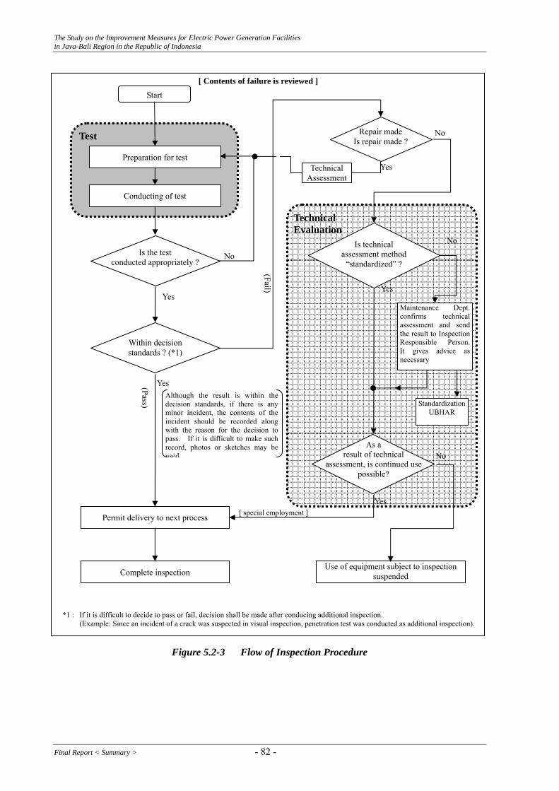
The Study on the Improvement Measures for Electric Power Generation Facilities in Java-Bali Region in the Republic of Indonesia
Start Preparation for test
Technical Assessment
Conducting of test
Is technical assessment method
“standardized” ?
Maintenance Dept. confirms technical assessment and send the result to Inspection Responsible Person. It gives advice as necessary
Yes Although the result is within the
decision standards, if there is any m
Standardization UBHAR i
pass. ecor
nor incident, the contents of the incident should be recorded along with the reason for the decision to
If it is difficult to make such r d, photos or sketches may be used.
Permit delivery to next process
Complete inspection
Use of equipment subject to inspection suspended
*1 : If it is difficult to decide to pass or fail, decision shall be made after conducing additional inspection. (Example: Since an incident of a crack was suspected in visual inspection, penetration test was conducted as additional inspection).
Yes
Test
(Pass)
No
[ Contents of failure is reviewed ]
Yes
No
Yes
No
Yes
No
[ special employment ]
Technical Evaluation
(Fail)
Is the test
conducted appropriately ?
Within decision standards ? (*1)
As a result of technical
assessment, is continued use possible?
Repair made
Is repair made ?
Figure 5.2-3 Flow of Inspection Procedure
Final Report < Summary > - 82 -
The Study on the Improvement Measures for Electric Power Generation Facilities in Java-Bali Region in the Republic of Indonesia
(5) Improvements toward reduction of the work period to rationalize the scheduled inspection work
The work period reduction items are employed in Japan at each work process of the scheduled precision inspection of boilers and turbines. We investigated whether or not each power station of Indonesian Power/PT PJB also performed such work process reduction items in the form of questionnaire.
The results are shown in Table 5.2-3. Since these work period reduction items seem to greatly contribute to ensuring high operation performance of the equipment and reduction of the operation and maintenance and repair costs, IP and PJB are recommended to re-review the items of the shortening methods for scheduled inspection at each power station.
- 83 - Final Report < Summary >
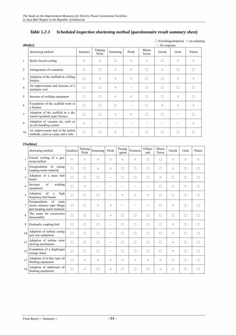
The Study on the Improvement Measures for Electric Power Generation Facilities in Java-Bali Region in the Republic of Indonesia
Table 5.2-3 Scheduled inspection shortening method (questionnaire result summary sheet)
○:Finishing[adoption] ×;un-adopting (Boiler) -: No response
shortening method Suralaya TanjungPriok Semarang Perak Muara
Tawar Gresik Grati Paiton
1 Boiler forced cooling × × ○ × × ○ × ×
2 Enlargement of a manhole × ○ × × ○ × ○ ○
3 Adoption of the scaffold in a lifting furnace ○ × × × ○ ○ × ×
4 An improvement and increase of a mechanic tool ○ ○ × - ○ ○ ○ ○
5 Increase of welding equipment ○ ○ × × ○ ○ × ○
6 Foundation of the scaffold work in a furnace ○ ○ ○ - ○ × × ×
7 Adoption of the scaffold in a sky station (gondola type) furnace ○ ○ × × ○ ○ - ○
9 Adoption of vacuum car, such as an ash handling system × - - - - - - ×
10 An improvement and of the polish methods, such as a pipe and a tube ○ ○ × - ○ ○ ○ ○
(Turbine)
shortening method Suralaya Tanjung Priok Semarang Perak Pesang
-garan Pemaron Gilima- nuk
MuaraTawar Gresik Grati Paiton
1 Forced cooling of a gas/ steam turbine × × × × × × ○ ○ × × ×
2 Encapsulation of casing keeping-warm material ○ ○ × × ○ ○ ○ ○ × ○ ○
3 Adoption of a mass bolt heater ○ ○ ○ - ○ ○ ○ × ○ ○ ○
4 Increase of welding equipment ○ × - - - - - ○ ○ × ○
5 Adoption of a high frequency bolt heater ○ ○ ○ - × × × ○ ○ ○ ○
7 Encapsulation of main steam entrance pipe flange part keeping-warm material
○ ○ × × - - - ○ × ○ ○
8 The crane for accessories disassembly ○ ○ ○ × ○ ○ ○ ○ ○ ○ ○
9 Hydraulic coupling bolt ○ ○ ○ - ○ ○ ○ ○ × ○ ○
10 Adoption of turbine casing jack rise equipment ○ ○ ○ - ○ ○ ○ ○ × ○ ○
11 Adoption of turbine rotor slewing mechanism ○ ○ ○ - ○ ○ ○ ○ × ○ ○
12 Foundation of a diaphragm storage stand ○ ○ ○ - ○ ○ ○ ○ × ○ ○
13 Adoption of in-line type oil flushing equipment ○ × × × × × × × ○ ○ ○
14 Adoption of additional oil flushing equipment ○ × ○ × ○ ○ ○ × ○ ○ ○
Final Report < Summary > - 84 -
The Study on the Improvement Measures for Electric Power Generation Facilities in Java-Bali Region in the Republic of Indonesia
5.3. Hydropower Stations
Based on the review and analysis as mentioned in Section 3, common issues to be studied for each power station are as follows at the moment. And selections of the items to be applied are recommended.
(1) Periodical Personnel Exchange between Operation Staff and Maintenance Staff
Number of operation staff and maintenance staff seems to be enough at the all power stations. However, the periodical personnel exchange between operation staff and maintenance staff is seldom carried out basically. The periodical personnel exchange is advisable in view of further upgrading the existing skill of the relevant staff.
(2) Flexible operation of scheduled periodical inspection
The periodical inspection in Indonesia consists of “Annual Inspection (AI)”, “General Inspection (GI)” and “Major Overhaul (MO)” basically and a certain inspection is conducted for almost every year in keeping with the schedule. However, considering the current frequency level of accidents, the flexible operation of scheduled periodical inspection including the extension of interval is advisable like Soedirman, which once simplified Annual Inspection (AI) to 6-month maintenance inspection and reduced the inspection duration to 30 hours for an example.
Concerning the Major Overhaul, MO is scheduled to conduct for every 40,000 hours basically. However, MO has not been carried out up to now at Soedirman power station because the operation has been in good condition even though the first commercial operation was about twenty (20) years ago (1998.11). If the unit operation is in good condition, non Major Overhaul is advisable.
(3) Better operation and maintenance work
Indication of the equipment name or machine’s abbreviation number is quite important to prevent miss operation and/or miss judgment. Therefore it is desirable to indicate above mentioned indications for safety work.
For the meters, pressure gauges, level gauges, indication of standard value or normal range is desirable if possible.
Description of the criteria is important in the recording sheets for easier judgment during maintenance work.
Measurement and recording of the unit operation sequence time (for instance “preparation finished, inlet valve full open, start the machine, excitation, in parallel”, and vice versa) during
- 85 - Final Report < Summary >

The Study on the Improvement Measures for Electric Power Generation Facilities in Java-Bali Region in the Republic of Indonesia
starting and stopping is one of the useful check to judge the machine condition.
The machine’s temperature is recorded closely at this moment for every power station however long term trend management is advised to continue closely for bearing temperature, stator winding temperature, generator cooling air temperature, etc.
Concerning the machine temperature management, comparison is quite important for actual gathered data and design data and/or commissioning test data.
In case that abnormal data is found out, urgent confirmation of machine condition and measurement system condition are needed. Also description of its cause is important to the recording sheets for the reference at long afterward maintenance. And it’s important the calibration of the detector if necessary.
(4) Better inspection work
It is considered, overhaul of the machine is not necessary only the reason that operation hours of the unit reach the scheduled period. (and also economical point of view)
Except the special case, it is considered that inspection of the bearing pad surface is not necessary at AI.
Detail description of repair work is desirable in the report for the reference at long afterward.
Polarity index (PI) test and Tan (δ) test are useful for the evaluation of stator winding. Therefore it desired that both of test is carried out during general inspection. (according to the periodical inspection reports, these tests ware carried out some cases completely and some cases incompletely.)
It is desirable to add the some performance test items after inspection.
Measurement of relation between guide vane opening and output is advised to confirm turbine performance.
During GI, carrying out the load rejection test is desirable to confirm the governor performance if it is permitted both of the power grid side and power station facility side.
Any performance record is not described in the some periodical inspection report. Test result is important not only to confirm the machine performance but also to compare the previous time record. Therefore description of the performance test record is advised in the report.
Final Report < Summary > - 86 -
The Study on the Improvement Measures for Electric Power Generation Facilities in Java-Bali Region in the Republic of Indonesia
5.4. Regulations related to Power Utilities Companies in Japan
This section introduces the related laws and regulations on Power Utilities Companies in Japan, especially on operation and maintenance, in order to serve MEMR, a control authority of Indonesia power sector, for her reference toward the improvement of her supervision and instruction.
Power utilities companies in Japan run their business in compliance with the following regulations and rules set by METI (Ministry of Economy, Trade and Industry).
(1) Electricity Utilities Industry Law (National Law : enacted in 1964, revised in 2005)
(2) Enforcement Order for Electricity Utilities Industry Law (Ministerial Decree: enacted in 1965, revised finally in 1996)
(3) Rules for Enforcement of Electricity Utilities Industry Law (Ministerial Decree: enacted in 1965, revised finally in 2006)
(4) Ministerial Decree for Technical Standards on (a) Electrical Facilities (enacted in 1965, revised finally in 2006) (b) Thermal Power Facilities (enacted in 1965, revised finally in 2006) (c) Hydropower Facilities (enacted in 1965, revised finally in 2006)
(5) Regulation on Electricity Related Accident Report (Ministerial Decree: enacted in 1965, revised finally in 2004)
(1) Electricity Utilities Industry Law
1) Conformance to Technical Standard (Clauses 39 & 40) 2) Establishment of Independent Safety Rule (Clause 42) 3) Chief Engineer (Clause 43)
(2) Enforcement Order for Electricity Utilities Industry Law
1) Collection of Report (Clause 8)
(a) The Minister of METI can let the Electric Power Supplier report the following issues: - Issues relating to management of electric power supply business - Issues relating to engineering work, operation and maintenance in connection
with security of power utility facilities - Issues relating to financial status - Issues relating to management of research services
- 87 - Final Report < Summary >
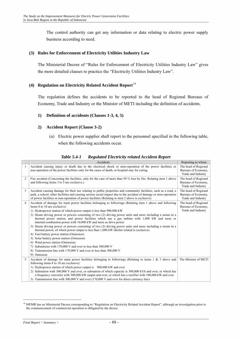
The Study on the Improvement Measures for Electric Power Generation Facilities in Java-Bali Region in the Republic of Indonesia
The control authority can get any information or data relating to electric power supply business according to need.
(3) Rules for Enforcement of Electricity Utilities Industry Law
The Ministerial Decree of “Rules for Enforcement of Electricity Utilities Industry Law” gives the more detailed clauses to practice the “Electricity Utilities Industry Law”.
(4) Regulation on Electricity Related Accident Report10
The regulation defines the accidents to be reported to the head of Regional Bureaus of Economy, Trade and Industry or the Minister of METI including the definition of accidents.
1) Definition of accidents (Clauses 1-3, 4, 5)
2) Accident Report (Clause 3-2)
(a) Electric power supplier shall report to the personnel specified in the following table, when the following accidents occur.
Table 5.4-1 Regulated Electricity related Accident Report
Accidents Reporting to whom 1 Accident causing injury or death due to the electrical shock or miss-operation of the power facilities or
non-operation of the power facilities only for the cases of death, or hospital stay for curing. The head of Regional Bureaus of Economy,
Trade and Industry 2 Fire accident (Concerning the facilities, only for the case of more than 50 % loss by fire. Relating item 1 above
and following items 3 to 5 are exclusive.) The head of Regional Bureaus of Economy,
Trade and Industry 3 Accident causing damage for their use relating to public properties and community facilities, such as a road, a
park, a school, other facilities and causing serious social impact due to the accident of damage or miss-operation of power facilities or non-operation of power facilities (Relating to item 2 above is exclusive)
The head of Regional Bureaus of Economy,
Trade and Industry 4 Accident of damage for main power facilities belonging to followings (Relating item 1 above and following
items 8 to 10 are exclusive) 1) Hydropower station of which power output is less than 900,000 kW 2) Steam driving power or powers consisting of two (2) driving power units and more including a steam in a
thermal power station, and power facilities which use a gas turbine with 1,000 kW and more or internal-combustion power with 10,000 kW and more as drive power
3) Steam driving power or powers consisting of two (2) driving power units and more including a steam in a thermal power, of which power output is less than 1,000 kW (Boiler related is exclusive)
4) Fuel battery power station (Omission) 5) Solar battery power station (Omission) 6) Wind power station (Omission) 7) Substations with 170,000 V and over to less than 300,000 V 8) Transmission line with 170,000 V and over to less than 300,000 V 9) Omission
The head of Regional Bureaus of Economy,
Trade and Industry
5 Accident of damage for main power facilities belonging to followings (Relating to items 1 & 3 above and following items 8 to 10 are exclusive) 1) Hydropower station of which power output is 900,000 kW and over 2) Substation with 300,000 V and over, or substation of which capacity is 300,000 kVA and over, or which has
a frequency converter with 300,000 kW output and over, or which has a rectifier with 100,000 kW and over 3) Transmission line with 300,000 V and over (170,000 V and over for direct currency line)
The Minister of METI
10 MEMR has no Ministerial Decree corresponding to “Regulation on Electricity Related Accident Report”, although an investigation prior to
the commencement of commercial operation is obligated by the decree.
Final Report < Summary > - 88 -

The Study on the Improvement Measures for Electric Power Generation Facilities in Java-Bali Region in the Republic of Indonesia
Accidents Reporting to whom 6 Accident of delivery failure of which delivery failure output is 7,000 kW more and 70,000 kW less and its
delivery failure time is more than one (1) hours, or of which delivery failure output is 70,000 kW more and 100,000 kW less and its delivery failure time is more than ten (10) minutes (Relating to item 3 above and following item 8 are exclusive)
The head of Regional Bureaus of Economy,
Trade and Industry
7 Accident of delivery failure of which delivery failure output is 100,000 kV and over, and its delivery failure time is ten (10) minutes and more (Relating to item 3 above and following item 9 are exclusive)
The Minister of METI
8 Accident causing other electricity power suppliers the delivery failure of which delivery failure output is 7,000 kW and over and less than 70,000 kW and their delivery failure time is one (1) hour and more, or of which delivery failure output is 100,000 kW and over, and their delivery failure time is ten (10) minutes and more due to the accident of damage or miss-operation of power facilities or non-operation of power facilities (Relating to item 3 above is exclusive)
The head of Regional Bureaus of Economy,
Trade and Industry
9 Accident causing other electricity power suppliers the delivery failure of which delivery failure output is 100,000 kW and over, and their delivery failure time is ten (10) minutes and more (Relating to item 3 above is exclusive)
The Minister of METI
10 Omission 11 Omission 12 Accident caused by the abnormal discharge passing through a spillway of a dam (Relating to item 3 above is
exclusive) The head of Regional Bureaus of Economy,
Trade and Industry
5.5. Guideline and Management Plan for Thermal Power Station
(1) Organization
A. The system for the operation, maintenance/Inspection management of the thermal power stations (hereinafter “Organization”) shall have clear description of the responsibility, authority and mutual relationships of the following departments (including the employees) and shall be documented. ① Department which manages the jobs on the operation and maintenance and safety
management. ② Department which implements the jobs on the operation and maintenance and safety
management. ③ Department which verifies the validity of the jobs on the operation and maintenance
and safety management.
(Remarks) “Safety management” means to make prior evaluation of safety when the condition of use such as for the modification of boilers, etc. and to utilize information on malfunctions and incidents inside and out of the company for the operation and maintenance management.
(2) Standards for the operation management and routine inspection
A. Table 5.5-1 of Boilers/Turbines, etc. Proper standards specifying operation management items shall be established and the operation management shall be implemented based on the standards and the results shall be recorded and kept.
B. Table 5.5-2 of Boilers/Turbines, etc. Proper standards specifying routine inspection of equipment, inspection points, inspection items, inspection method, standards for adequacy, etc. shall be established and the routine inspection shall be conducted based on the standards and the results shall be recorded and kept.
- 89 - Final Report < Summary >

The Study on the Improvement Measures for Electric Power Generation Facilities in Java-Bali Region in the Republic of Indonesia
Table 5.5-1 Items for Operation Management Equipment Items for Operation Management Remarks
・Steam pressure & temperature at outlet of Superheater & Resuperheater 1 ・Boiler vaporization volume or feed water flow rate ・Drum water level 2 ・Drum pressure 2 ・Quality of boiler water and feed water ・Fuel used ・Spray water quantity of superheater and reheater or steam temperature before and after
spraying 2
Boilers
・Boiler efficiency 3 ・Output of the generators ・Steam pressure and temperature upstream of Main Steam Stop Valve and upstream of
Re-heater Stop Valve
・Steam turbine speed 2 ・Steam turbine exhaust pressure ・Steam turbine extraction pressure and temperature 2 ・Oil pressure at inlet of steam turbine bearings 2 ・Temperature of steam turbine bearings & oil temperature at outlet of bearings 2 ・Characteristics of lubricating oil ・Steam turbine control hydraulic pressure 2 ・Opening of steam regulating valve 2 ・Vibration of steam turbines 2 ・Steam turbine efficiency 3
Steam turbines
・Expansion and difference in expansion of shaft and casing (only for those with 2 or more casings) 2
・Output of generators 4 ・Gas turbine speed 5 ・Discharge pressure of Gas turbine air compressor 2 ・Gas temperature at gas turbine inlet 6 ・Oil pressure at gas turbine shaft inlet 2 ・Gas turbine shaft temperature or oil temperature at gas turbine shaft outlet 2 ・Characteristics of lubricant oil ・Gas turbine control fluid temperature 2 ・Vibrations of gas turbines 2 ・Gas turbine air compressor inlet air temperature 7
Gas turbines
・Fuel used 8 ・Gas turbine efficiency
Note 1: In the case of the unit system, the pressure and temperature may be covered by those upstream of Main Steam Stop Valve and
upstream of Reheating Steam Stop Valve. Note 2: Recording of the data is not always required. However, any abnormality in light of the operation management standards shall be
recorded. Note 3: In the case of the unit system, the boiler efficiency may be covered by the general efficiency of the unit. Note 4: The data may be covered by generation power output. Note 5: In the case of free turbine type gas turbine, the data shall be gas generator speed and output turbine speed. Although recording is not
always required, any abnormality in light of the operation management standards shall be recorded. Note 6: The data may be covered by gas temperature at the gas turbine outlet. Note 7: In the case of indoor equipment, the temperature may be air temperature at air intake of power generation plant, and in the case of
outdoor equipment, it may be ambient temperature. Although recording is not always required, any abnormality in light of the operation management standards shall be recorded.
No.8: The efficiency may be covered by the general efficiency.
Final Report < Summary > - 90 -

The Study on the Improvement Measures for Electric Power Generation Facilities in Java-Bali Region in the Republic of Indonesia
Table 5.5-2 Routine Inspection Items Equipment Routine Inspection Item
Boiler safety valve ・Steam leaks from valve seats
Main pipeline ・Abnormality of hangers ・Leaks of steam and gas from pipeline ・Vibration of pipeline
Boiler or furnace ・Combustion status ・Abnormality inside the furnace
HRSG ・Damage to boiler body or tubes ・Drum two-tone water level, steam leaks, damage to glass
Steam turbines
・Vibration, abnormal noise ・Steam leaks from casing ・Loosening of bolts & nuts ・Vibration, abnormal noise, species, superheating and waste oil of bearings
Main heat exchanger, etc. ・Steam leaks ・Water level
Gas turbines
・Vibration, abnormal noise, superheating and other abnormality ・Leaks of gas, lubricant oil, etc. ・Abnormality of scaffolding, supporting metal fittings, and loosening of bolts & nuts ・Vibration, abnormal noise superheating and waste oil condition of bearings
Gas turbine air compressor
・Vibration, abnormal noise and other abnormality ・Leaks of lubricant oil ・Abnormality of scaffolding, supporting metal fittings, and loosening of bolts & nuts ・Vibration, abnormal noise superheating and waste oil condition of bearings
Generators
・Vibration, abnormal noise, offensive smell ・Leakage of hydrogen gas ・Quantity and temperature of waste oil from bearings, bubbling condition ・Vibration of CT bushing and phase separating bus bar, leak from water leakage alarm ・Wear condition, vibration of the brush, superheating and connecting condition of lead
lines Main revolver
excluding Steam turbines, Gas turbines and Gas turbine air compressors
・Vibration, abnormal noise and temperature increase of the body ・Steam and gas leaks from glands ・Oil temperature, oil surface and oil leaks from bearings
Main valves ・Vibration, abnormal noise of valves ・Leaks of steam, gas, etc. from valve glands, valve seats ・Abnormality of activating source
Main transformer ・Superheating, offensive smell, buzzing and discoloring condition ・Conservator oil surface, discoloring condition of breather silica gel
Electric equipment
・Abnormality of display lights on operation panels, monitoring panels, distribution panel switching device, Switch-on condition of alarm display
・Superheating, offensive odor and discoloring and terminal tightening condition ・ Vibration, abnormal noise, offensive smell of motor transformer, illumination
transformer ・Damage condition of indicators and recorders, etc. ・Damage condition and any difference by comparison between indicated values and
standard values on instruments such as indicators and recorders Instruments ・Condition of ink loss from recorders and of chart processing ・Indicated value on , leaks from detector
- 91 - Final Report < Summary >
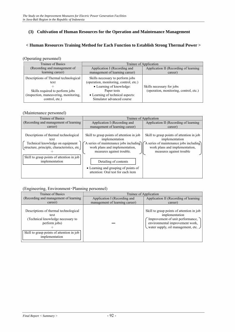
The Study on the Improvement Measures for Electric Power Generation Facilities in Java-Bali Region in the Republic of Indonesia
(3) Cultivation of Human Resources for the Operation and Maintenance Management
< Human Resources Training Method for Each Function to Establish Strong Thermal Power > (Operating personnel)
Trainee of Application Trainee of Basics (Recording and management of
learning career) Application I (Recording and
management of learning career) Application II (Recording of learning
career) Descriptions of Thermal technological
text +
Skills required to perform jobs
Skills necessary to perform jobs (operation, monitoring, control, etc.)
• Learning of knowledge: Paper tests
• Learning of technical aspects: Simulator advanced course
Skills necessary for jobs (operation, monitoring, control, etc.)
(inspection, maneuvering, monitoring, control, etc.)
(Maintenance personnel)
Trainee of Application Trainee of Basics (Recording and management of learning
career) Application I (Recording and
management of learning career) Application II (Recording of learning
career)
Descriptions of thermal technological text
Technical knowledge on equipment structure, principle, characteristics, etc.
+
Skill to grasp points of attention in job
implementation A series of maintenance jobs including
work plans and implementation, measures against trouble.
• Learning and grasping of points of attention: Oral test for each item
Skill to grasp points of attention in job implementation
A series of maintenance jobs including work plans and implementation,
measures against trouble
(Engineering, Environment・Planning personnel)
Trainee of Application Trainee of Basics (Recording and management of learning
career) Application I (Recording and
management of learning career) Application II (Recording of learning
career)
Descriptions of thermal technological text
Skill to grasp points of attention in job implementation
(Technical knowledge necessary to perform jobs)
Improvement of unit performance, environmental improvement work, water supply, oil management, etc.
━ +
Skill to grasp points of attention in job implementation Detailing of contents
Skill to grasp points of attention in job implementation
Final Report < Summary > - 92 -
The Study on the Improvement Measures for Electric Power Generation Facilities in Java-Bali Region in the Republic of Indonesia
5.6. Guideline and Management Plan for Hydropower Station
(1) Items for operation job
Regarding the operation job for hydro power station, the main daily affairs are as ① start/ stop, open/close etc. of the facilities, ② supervision of the machines, ③ daily patrol check of the facilities, ④ open/close and locking of the electrical switches, valves, protection relays, etc. for maintenance work
① During operation of the facilities, preventing the miss operation is the most important. Therefore, operation of the main machines such as unit start/stop, open/close of main circuit breakers and disconnecting switches are usually carried out by operation staff under the chief engineer’s supervision and instruction step by step.
And the operation job such as open/close the valves, start/stop the auxiliary equipment and locking the relays are permissible in case that the job is in accordance with the approved operation procedure.
② Regarding the supervision of the facilities, careful watching for meters is required at any time. And daily trainings are important to recover from the abnormal condition quickly.
③ Regarding the daily patrol check of the facilities, not only the visual check but also the five senses check are important. Also for easier detecting the abnormal condition of the equipment, the daily check sheet had better include the indication of normal/allowable ranges of the relevant meters and detectors, etc. and/or description of the criteria.
The patrol route is carefully considered to prevent the facilities from missing the inspection and for easier patrol.
④ Before starting the inspection work or repairing work, perfect lock of the related switches, valves, protection relays, and so on are very important in view of safety work of maintenance staffs and the prevention of the bad influence to the power grid.
For these purposes, it is quite important that locking job is carried out based on the approved operation procedure. And it is the same manner during the restoration.
To prevent any miss operation, it is desirable to attach the indicators and/or tags nearby such as machine’s abbreviation number, each equipment name, valve number, valve open/close condition, flow direction and classification of fluid on the pipes.
(2) Items for Maintenance Job
Regarding the maintenance job for hydro power station, the main affairs are as ① planning, action and evaluation of periodical inspections such as weekly, monthly, yearly and reflection of the inspection result on the next inspection plan, ② in case of trouble or incident, recovering, investigation of the causes and study on prevention of recurrence, ③ examination
- 93 - Final Report < Summary >
The Study on the Improvement Measures for Electric Power Generation Facilities in Java-Bali Region in the Republic of Indonesia
and management of setting values of protection relays, ④ management of design drawings and calculation sheets, instruction documents, commissioning test records and periodical inspection reports, etc.
① For the planning of the inspection schedule and items, it is very important that inspection frequency is decided under consideration of reliability and level of importance of each facility. And the inspection sheet is proposed to include the criterion measure/average level in order to judge whether the machine condition is normal or abnormal at a glance.
Regarding the yearly inspections such as Annual Inspection and General Inspection, these are relatively large scale inspections, therefore it is important that inspection items is decided in advance under the close consideration of previous inspection results. In case that the items which were judged as “good”, it is better to reconsider the extension of the inspection period.
Especially concerning Major Overhaul, it is large scale inspection and gives influence to the power grid reliability and also economical viewpoint, therefore it is quite important that the timing of the M.O is considered closely actual machine condition.
It is not necessary to carry out M.O only by the reason that unit operating hours reach the planned M.O timing.
In the inspection report, detail description of repaired work and operation test results are especially desired for serving subsequent inspections.
② In case of trouble or incident, of course quick recover is very important and it is also important to investigate it’s cause closely and to prevent recurrence of same trouble.
③ Regarding the protection relays, review of setting values are needed sometime according to changing the power grid condition and/or changing machine’s operation condition. Therefore, it is important to prepare rule of the calculation method of protection relays.
④ Drawings, calculation sheets, instruction documents, erection records and test records during the construction period, periodical inspection reports, and so on are quite important for good maintenance. Therefore preparation the managing method is important to prevent any missing the materials.
Final Report < Summary > - 94 -

The Study on the Improvement Measures for Electric Power Generation Facilities in Java-Bali Region in the Republic of Indonesia
(3) Items for Training
System of Yearly Staff Training Policy Division Manager of power station Each staff
Policy
Target P
Planning
D Practice
Evaluation
C
Analysis
A Utilization
Contents of Training for Each Skill Level
Stage 1 Stage 2 Stage 3
Yearly training policy
Setting the target Setting the target
Training program Training plan Skill up by own (planning)
Practice On the job training Skill up by own (practice)
Evaluation of the staff skill
Self evaluation for skill up
Job rotation
Evaluation, analysis & conduct of all staff
skill improvement
Analysis of result of training
Stage 4 Stage 5
Mai
nten
ance
Maintenance of GIS
Maintenance of turbine &generator
Over haul work of turbine & generator
Maintenance of transformer
Maintenance of GOV & AVR
Ope
ratio
n
Individual training section or P/S level
(Setting training curriculum
according to own specialty)
Individual training section or P/S level
(Same as left)
Self study Individual training section or P/S level(Same as left)
Individual training section or P/S level (Same as left)
Operation of hydro power
Role of senior operator and senior maintenance staff
- 95 - Final Report < Summary >

The Study on the Improvement Measures for Electric Power Generation Facilities in Java-Bali Region in the Republic of Indonesia
6. Technology Transfer 6.1. Thermal Power Station
(1) Background
Based on the above investigation, the following issues are confirmed for RLA. 1) LITBANG, PLN’s research institute, has already RLA technology for a boiler. 2) RLA for a turbine and a generator has been carried out by manufacturers and LITBANG
hopes for technology transfer of RLA regarding a turbine and a boiler. 3) Since some power stations have already exceeded the design life time, the execution of
RLA is required.
Considering the deterioration of facilities, rehabilitation/modification works in the past and effectiveness of RLA technology for Indonesia side addition to the above confirmation, the contents of technology transfer for a boiler, a turbine and a generator had been set by the Study Team and consensus was obtained in the 2nd Workshop.
(2) Technology Transfer
1) Turbine 1. Thermal Power Station
RLA has been conducted by turbine manufacturers. 2. LITBANG
LITBANG hopes for technology transfer of RLA
Deterioration of turbine might be caused by various factors, such as creep, fatigue and embrittlement etc. → Among the above factors, deterioration by embrittlement is important because
turbine failure by embrittlement causes the serious damage.
Example of burst of turbine rotor due to embrittlement (USA Gallatin #2 1974)
Final Report < Summary > - 96 -
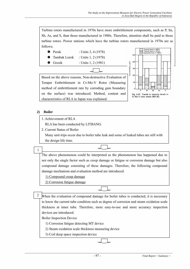
The Study on the Improvement Measures for Electric Power Generation Facilities in Java-Bali Region in the Republic of Indonesia
Turbine rotors manufactured in 1970s have more embrittlement components, such as P, Sn, Sb, As, and S, than those manufactured in 1980s. Therefore, attention shall be paid to those turbine rotors. Power stations which have the turbine rotors manufactured in 1970s are as follows;
Perak : Units 3, 4 (1978) Tambak Lorok : Units 1, 2 (1978) Gresik : Units 1, 2 (1981)
Based on the above reasons, Non-destructive Evaluation of Temper Embrittlement in Cr-Mo-V Rotor (Measuring method of embrittlement rate by corroding gain boundary on the surface) was introduced. Method, content and characteristics of RLA in Japan was explained.
2) Boiler 1. Achievement of RLA RLA has been conducted by LITBANG. 2. Current Status of Boiler Many unit trips occur due to boiler tube leak and some of leaked tubes are still with the design life time.
The above phenomenon could be interpreted as the phenomenon has happened due to not only the single factor such as creep damage or fatigue or corrosion damage but also compound damage consisting of these damages. Therefore, the following compound damage mechanism and evaluation method are introduced.
1
1) Compound creep damage 2) Corrosion fatigue damage
When the evaluation of compound damage for boiler tubes is conducted, it is necessary to know the current tube condition such as degree of corrosion and steam oxidation scale thickness at inner tube. Therefore, more easy-to-use and more accuracy inspection devices are introduced.
2
Boiler Inspection Device 1) Corrosion fatigue detecting MT device 2) Steam oxidation scale thickness measuring device
3) Coil deep space inspection device
- 97 - Final Report < Summary >
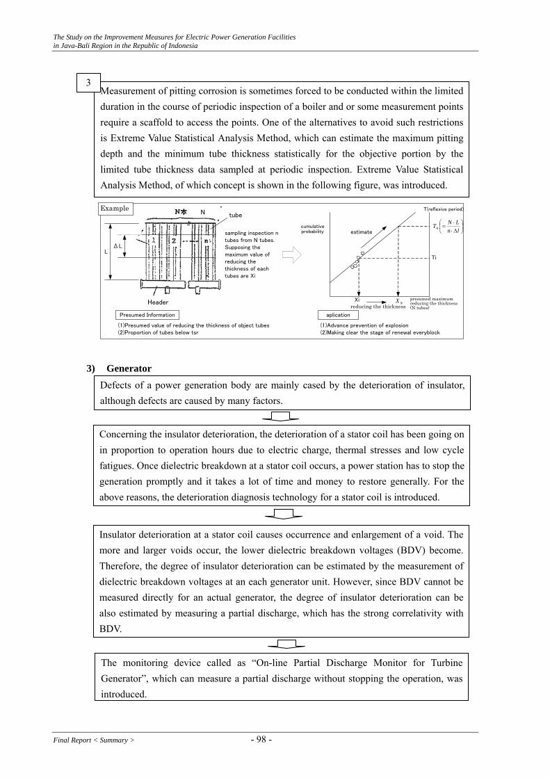
The Study on the Improvement Measures for Electric Power Generation Facilities in Java-Bali Region in the Republic of Indonesia
Defects of a power generation body are mainly cased by the deterioration of insulator, although defects are caused by many factors.
Insulator deterioration at a stator coil causes occurrence and enlargement of a void. The more and larger voids occur, the lower dielectric breakdown voltages (BDV) become. Therefore, the degree of insulator deterioration can be estimated by the measurement of dielectric breakdown voltages at an each generator unit. However, since BDV cannot be measured directly for an actual generator, the degree of insulator deterioration can be also estimated by measuring a partial discharge, which has the strong correlativity with BDV.
The monitoring device called as “On-line Partial Discharge Monitor for Turbine Generator”, which can measure a partial discharge without stopping the operation, was introduced.
Concerning the insulator deterioration, the deterioration of a stator coil has been going on in proportion to operation hours due to electric charge, thermal stresses and low cycle fatigues. Once dielectric breakdown at a stator coil occurs, a power station has to stop the generation promptly and it takes a lot of time and money to restore generally. For the above reasons, the deterioration diagnosis technology for a stator coil is introduced.
sampling inspection ntubes from N tubes.Supposing themaximum value ofreducing thethickness of eachtubes are Xi
(1)Presumed value of reducing the thickness of object tubes(2)Proportion of tubes below tsr
Presumed Information
(1)Advance prevention of explosion(2)Making clear the stage of renewal everyblock
aplication
tube
LΔL
Header
ExampleN
Xireducing the thickness
cumulativeprobability
Ti
T(reflexive period)
⎟⎠⎞
⎜⎝⎛
Δ⋅⋅
=ln
LNTN
NX
estimate
presumed maximum reducing the thickness(N tubes)
Measurement of pitting corrosion is sometimes forced to be conducted within the limited duration in the course of periodic inspection of a boiler and or some measurement points require a scaffold to access the points. One of the alternatives to avoid such restrictions is Extreme Value Statistical Analysis Method, which can estimate the maximum pitting depth and the minimum tube thickness statistically for the objective portion by the limited tube thickness data sampled at periodic inspection. Extreme Value Statistical Analysis Method, of which concept is shown in the following figure, was introduced.
3
3) Generator
Final Report < Summary > - 98 -
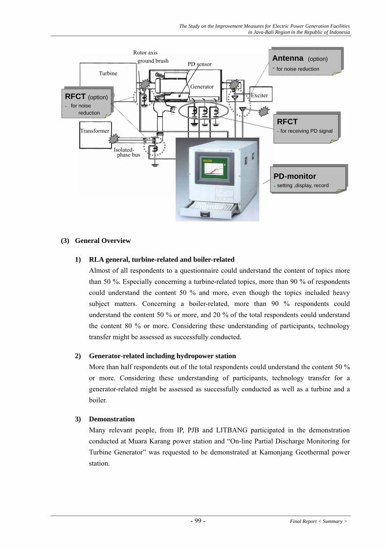
The Study on the Improvement Measures for Electric Power Generation Facilities in Java-Bali Region in the Republic of Indonesia
PD sensorground brush
Generator
Turbine
Exciter
Transformer
Isolated- phase bus
Partial discharge monitor
PD - monitor - setting ,display, record
PD - monitor - setting ,display, record
Antenna (option)- for noise reduction
Antenna (option)- for noise reduction
RFCT (option)- for noise
reduction
RFCT (option) - for noise
reduction RFCT - for receiving PD
signal
RFCT - for receiving PD signal
Rotor axis
(3) General Overview
1) RLA general, turbine-related and boiler-related Almost of all respondents to a questionnaire could understand the content of topics more than 50 %. Especially concerning a turbine-related topics, more than 90 % of respondents could understand the content 50 % and more, even though the topics included heavy subject matters. Concerning a boiler-related, more than 90 % respondents could understand the content 50 % or more, and 20 % of the total respondents could understand the content 80 % or more. Considering these understanding of participants, technology transfer might be assessed as successfully conducted.
2) Generator-related including hydropower station More than half respondents out of the total respondents could understand the content 50 % or more. Considering these understanding of participants, technology transfer for a generator-related might be assessed as successfully conducted as well as a turbine and a boiler.
3) Demonstration Many relevant people, from IP, PJB and LITBANG participated in the demonstration conducted at Muara Karang power station and “On-line Partial Discharge Monitoring for Turbine Generator” was requested to be demonstrated at Kamonjang Geothermal power station.
- 99 - Final Report < Summary >

The Study on the Improvement Measures for Electric Power Generation Facilities in Java-Bali Region in the Republic of Indonesia
7/13,14 Technology Transfer 7/27 Confirmation of Terminal Box at
Muara Karaang Unit 1 Generator
7/27 Result of PDM at Muara Karang Unit 1 6.2. Hydropower Station
(1) Background
During the course of the above investigation, RLA by utilization of non-destructive examination and electrical insulation examination has not been conducted for hydropower stations. But the necessity and effect of conducting RLA were well understood and they showed their high interest in RLA. The application of RLA to old hydropower stations are well expected to contribute to prevent serious accidents by preventive maintenance.
Based on the above conditions, technology transfer for RLA, by using non-destructive examination method and electrical insulation examination for a generator stator aiming the establishment of preventive maintenance, is to be conducted. The following three (3) topics for the technology transfer were confirmed by the discussion with the Indonesia side and the Study Team in the 3rd Field Work based on the results of the 1st Field Work. - Remaining Life Assessment by using non-destructive examination results for a casing and a
stay vane - Remaining Life Assessment by using the management of welding volume for a turbine
runner - Remaining Life Assessment by using the results of electrical insulation examination for a
generator stator
Final Report < Summary > - 100 -

The Study on the Improvement Measures for Electric Power Generation Facilities in Java-Bali Region in the Republic of Indonesia
(2) Technology Transfer
1) RLA by using the non-destructive examination results for a casing and a stay vane
The RLA is to evaluate the remaining life by firstly modeling the defects resulting from an ultrasonic defecting device as one of the non-destructive method, and by application of fracture mechanism considering the operating stresses and material characteristics secondly. The concrete evaluation method and points to remember were explained by using the actual samples in the technology transfer.
2) RLA by using the management of welding volume for a turbine runner
The RLA is to evaluate the remaining life of a runner by digitalizing the damage, utilizing an evaluation standard, caused by the repair works for a runner, such as welding volume, stress relief, and deformation. The concrete evaluation method and points to remember were explained by using the actual samples in the technology transfer.
3) RLA by using the results of electrical insulation examination for a generator stator coil
The RLA is to evaluate the remaining life of a stator coil by estimating the dielectric strength resulting from the measurements of the maximum partial discharge and tan δ carried out for an electrical insulation examination for a generator stator coil. The concrete evaluation method and points to remember were explained by using the actual samples in the technology transfer.
(3) General Overview
1) RLA Technology Transfer for Hydropower Station
More than half respondents out of the total respondents could understand the content 50 % or more. Considering these understanding of participants, technology transfer for a generator-related might be assessed as successfully conducted.
2) Demonstration of PDM
Many relevant people, from IP, PJB and LITBANG participated in the demonstration conducted at Cirata Hydropower Station. Many questions arose in the demonstration, such as - Can the remaining life of a stator coil be evaluated by only the measurement of partial
discharge? - Can the concrete defective coil portion be identified by the PDM? - Please more explanation about the occurrence mechanism of void causing insulation
deterioration. - Please show us the examples of measuring results conducted at power stations in the
KANSAI.
- 101 - Final Report < Summary >
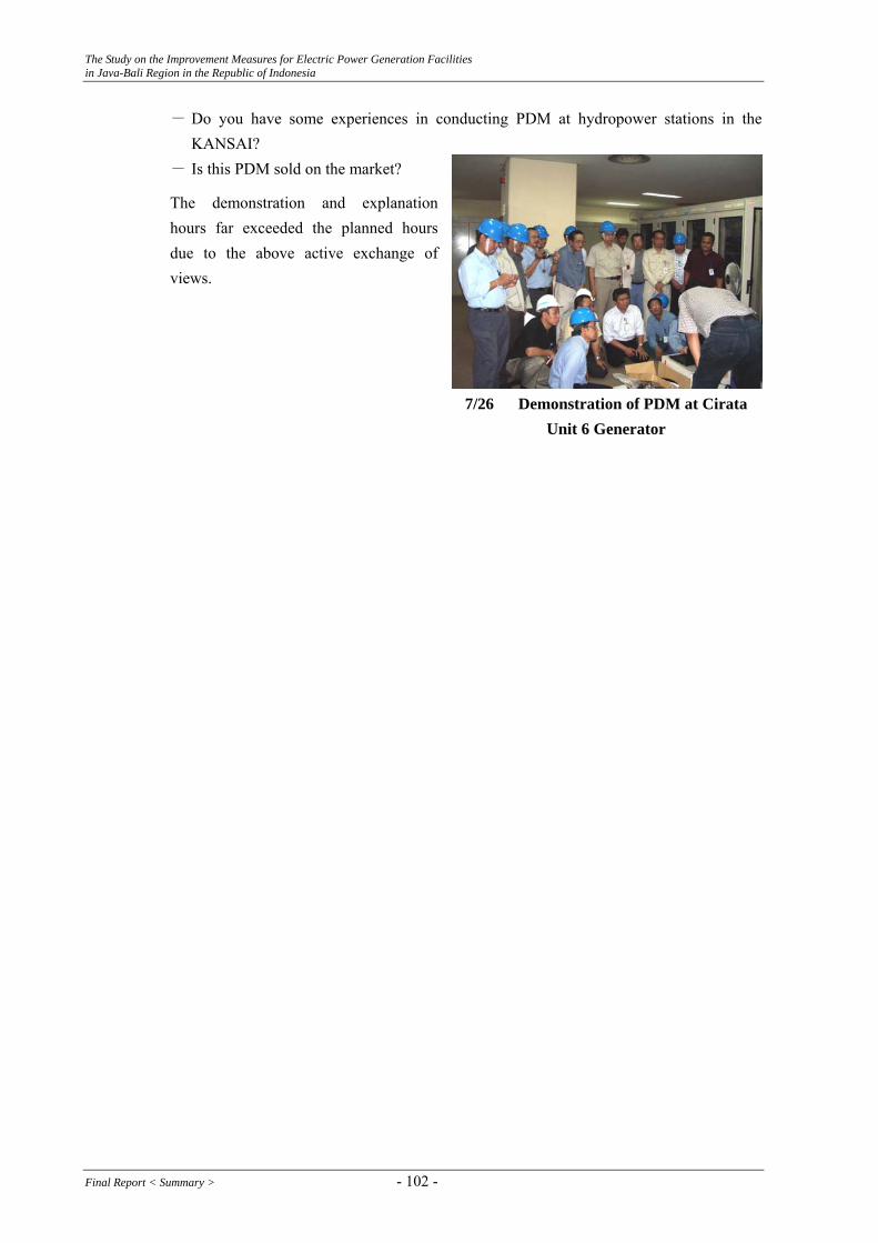
The Study on the Improvement Measures for Electric Power Generation Facilities in Java-Bali Region in the Republic of Indonesia
- Do you have some experiences in conducting PDM at hydropower stations in the KANSAI?
- Is this PDM sold on the market?
The demonstration and explanation hours far exceeded the planned hours due to the above active exchange of views.
7/26 Demonstration of PDM at Cirata Unit 6 Generator
Final Report < Summary > - 102 -

The Study on the Improvement Measures for Electric Power Generation Facilities in Java-Bali Region in the Republic of Indonesia
7. Conclusion and Recommendation In the course of the one-year Study, the Study team visited sixteen (16) power stations, LITBANG, Suralaya Training Center, P3B and local dispatching center in Java-Bali region and collected a lot of relevant data/information in the meetings relating to power generation facilities and O&M. Further more, technology transfer relating to Remaining Life Assessment was also conducted including the demonstration at Cirata hydropower station and Muara Karang thermal power station. Addition to the above activities and studies, three (3) Workshops and three (3) Steering Committees were held and useful comments were made by the participants. Based on the above activities and studies, the following conclusions and recommendations are induced. Table 7-2 shows the summary of objective power stations in respect to their operation and maintenance performance. 7.1. Conclusion 7.1.1. Thermal Power Stations
(1) The Study Team analyzed the operation performance on June 20, 2005 which caused the serious power supply shortage in Java-Bali region, for the objective power stations. The results of analyses are; (a) About 25 % of the total installed capacity with 12,660 MW were forced to stop the
operation and causing the derating due to planned outages and forced outages. (b) The derating caused by fuel issues was about 6 %. The 6 % doesn’t include
shutdown of power station due to the stop of fuel supply.
(2) Concerning the gas and oil related, it is confirmed that MEMR is a regulator and a policy maker, and BPMIGAS (Executive Agency for Upstream Oil and Gas Business Activity) under the direct control of the president is a regulator and a supervisor relating to the gas and oil business.
(3) Development of new coal fired power plants with the total capacity up to 10,000 MW through out Indonesia for the next three years aiming the energy diversification was announced on May 22, 2006 by PLN during the Study Period. According to a newspaper, the development of new coal fired power plant seems more likely to affect the current thermal power stations in some form, especially HSD firing power stations.
(4) The Study Team analyzed accidents and troubles (times and hours) for 75 units among the objective thermal power stations from 2003 to 2005. The results of analysis are; (a) The number and hours of forced outages show the tendency to increase of forced
outage as a whole.
- 103 - Final Report < Summary >
The Study on the Improvement Measures for Electric Power Generation Facilities in Java-Bali Region in the Republic of Indonesia
(b) The main cause of forced outages is due to the defect or malfunction of Instrumentation and Control (I & C), which might be caused by maladjustment at the periodic inspection, aged deterioration and sometimes by human errors.
Based on the above analysis, measures for “Improvement to preventive routine accidents and troubles” and “Improvement of scheduled inspection work from operation aspect” are prepared by the Study Team.
(5) It is confirmed that PLN’s affiliated companies IP and PJB report their financial status to PLN but don’t submit the accident reports to PLN. And it is also confirmed that MEMR, the control authority for the power sector, is not normally engaged with the electricity related accidents except for the case, such as the large area blackout in Java-Bali region which occurred on August 18, 2005 causing the serious social impact and MEMR has been investigating the cause of and responsibility for the blackout.
(6) In respect of maintenance system for a power station, it is confirmed that IP adopts the Maintenance System Based on Location of Facilities and PJB adopts the Maintenance System Based on Category of Maintenance Methods, and both maintenance systems are different.
(7) It is confirmed that currently Suralaya, Muara Karang, Paiton and Saguling power stations are under procedure of JBIC export credit. Addition to the above four (4) plans, it is also confirmed that PLN has intention to carry out further rehabilitation and modification plans for Suralaya unit 3 and unit 4, and Muara Karang PLTU unit 4 and unit 5, which are excluded in the current JBIC export credit due to the limit of PLN budget.
(8) The Study Team proposed the repowering plans for Tambak Lorok, Grati and Gilimanuk power stations to be converted from the existing PLTU/PLTG to PLTGU. Along with the repowering plans, oil reduction plans are also proposed for UBP basis, such as UBP Semarang, UBP Perak/Grati and UBP Bali.
(9) The economic and financial analyses were conducted for the six (6) proposed plans. The economic analysis resulted in good EIRR exceeding the social discount of 12 % under the current high fuel oil prices. However, the financial analysis resulted in pessimistic project FIRR below the opportunity cost of 12 %. Measures to implement the proposed plans are presented by the Study Team.
(10) The Study Team conducted scoping for the six (6) proposed plans from the viewpoint of Environmental and Social Consideration. And a draft KA-ANDAL is prepared by the Study Team.
Final Report < Summary > - 104 -

The Study on the Improvement Measures for Electric Power Generation Facilities in Java-Bali Region in the Republic of Indonesia
7.1.2. Hydropower Stations
(1) Regarding four (4) hydropower stations, no derating was observed. Operation and maintenance are well managed.
(2) Some rehabilitation/modification plans for Saguling, Cirata, Soedirman and Sutami were proposed by the Study Team.
(3) The water quality deterioration in the reservoir, due to the inflow of domestic wasted water and factory effluent, is causing the serious damage to the water cooling system at Cirata and Saguling hydropower stations. It is confirmed that Replacement of water cooling piping is under progress at Cirata by PJB own budget or planned at Saguling by JBIC export credit.
(4) It is confirmed that reservoir operation rule for Saguling and Cirata is developed by the Coordination Committee and the generation use of the Citarum River is set at the lowest priority among the utilizations of the Citarum River.
7.1.3. Power Facilities (Transmission Line and Substation)
(1) Construction of southerly 500 kV transmission line with two circuits was completed in June 2006.
(2) It is confirmed that in 500 kV transmission line, only the section which is restricted by system stability is not satisfied with N-1 criteria and as for 500/150 kV transformers, the ratio of transformers whose availability is over 60 % accounts for 90 % or more of the total, and almost of transformers do not meet N-1 criteria.
(3) The Study Team analyzed the accidents relating to transmission lines and transformers. The result is that the number of service interruption due to transmission line is small, but one due to transformer faults has been increasing year by year.
(4) It is confirmed that generators owned by IP and PJB do not carry out governor free operation even though Grid Code regulates all power stations have to be operated with governor free mode. It is also confirmed that generators owned by IPPs and PLN (Muara Tawar) are operated with governor free mode.
7.1.4. Technology Transfer for Remaining Life Assessment (RLA)
(1) It is confirmed that LITBANG, PLN’s research institute, has many experiences in RLA for boiler related, while RLA for turbines and generators is conducted by manufacturers, and RLA has not been conducted by Indonesia side for hydropower stations.
(2) Based on the current situation of RLA in Indonesia, technology transfer relating to RLA
- 105 - Final Report < Summary >
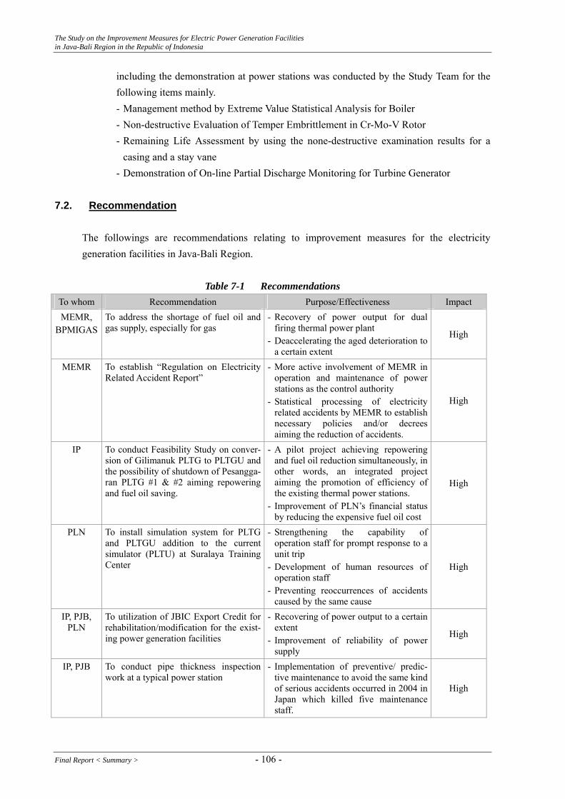
The Study on the Improvement Measures for Electric Power Generation Facilities in Java-Bali Region in the Republic of Indonesia
including the demonstration at power stations was conducted by the Study Team for the following items mainly. - Management method by Extreme Value Statistical Analysis for Boiler - Non-destructive Evaluation of Temper Embrittlement in Cr-Mo-V Rotor - Remaining Life Assessment by using the none-destructive examination results for a
casing and a stay vane - Demonstration of On-line Partial Discharge Monitoring for Turbine Generator
7.2. Recommendation
The followings are recommendations relating to improvement measures for the electricity generation facilities in Java-Bali Region.
Table 7-1 Recommendations To whom Recommendation Purpose/Effectiveness Impact MEMR,
BPMIGAS To address the shortage of fuel oil and gas supply, especially for gas
- Recovery of power output for dual firing thermal power plant
- Deaccelerating the aged deterioration to a certain extent
High
MEMR To establish “Regulation on Electricity Related Accident Report”
- More active involvement of MEMR in operation and maintenance of power stations as the control authority
- Statistical processing of electricity related accidents by MEMR to establish necessary policies and/or decrees aiming the reduction of accidents.
High
IP To conduct Feasibility Study on conver-sion of Gilimanuk PLTG to PLTGU and the possibility of shutdown of Pesangga-ran PLTG #1 & #2 aiming repowering and fuel oil saving.
- A pilot project achieving repowering and fuel oil reduction simultaneously, in other words, an integrated project aiming the promotion of efficiency of the existing thermal power stations.
- Improvement of PLN’s financial status by reducing the expensive fuel oil cost
High
To install simulation system for PLTG and PLTGU addition to the current simulator (PLTU) at Suralaya Training Center
- Strengthening the capability of operation staff for prompt response to a unit trip
- Development of human resources of operation staff
- Preventing reoccurrences of accidents caused by the same cause
PLN
High
IP, PJB, PLN
To utilization of JBIC Export Credit for rehabilitation/modification for the exist-ing power generation facilities
- Recovering of power output to a certain extent
- Improvement of reliability of power supply
High
IP, PJB To conduct pipe thickness inspection work at a typical power station
- Implementation of preventive/ predic-tive maintenance to avoid the same kind of serious accidents occurred in 2004 in Japan which killed five maintenance staff.
High
Final Report < Summary > - 106 -
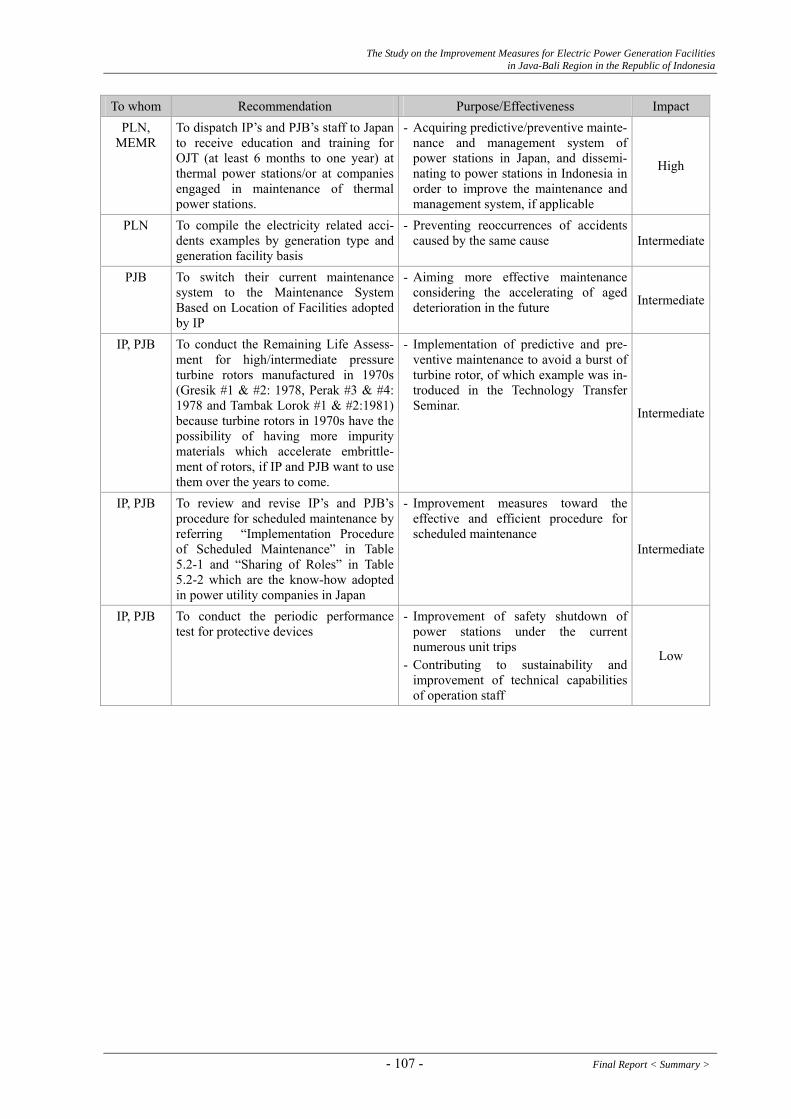
The Study on the Improvement Measures for Electric Power Generation Facilities in Java-Bali Region in the Republic of Indonesia
To whom Recommendation Purpose/Effectiveness Impact PLN,
MEMR To dispatch IP’s and PJB’s staff to Japan to receive education and training for OJT (at least 6 months to one year) at thermal power stations/or at companies engaged in maintenance of thermal power stations.
- Acquiring predictive/preventive mainte-nance and management system of power stations in Japan, and dissemi-nating to power stations in Indonesia in order to improve the maintenance and management system, if applicable
High
PLN To compile the electricity related acci-dents examples by generation type and generation facility basis
- Preventing reoccurrences of accidents caused by the same cause Intermediate
PJB To switch their current maintenance system to the Maintenance System Based on Location of Facilities adopted by IP
- Aiming more effective maintenance considering the accelerating of aged deterioration in the future Intermediate
To conduct the Remaining Life Assess-ment for high/intermediate pressure turbine rotors manufactured in 1970s (Gresik #1 & #2: 1978, Perak #3 & #4: 1978 and Tambak Lorok #1 & #2:1981) because turbine rotors in 1970s have the possibility of having more impurity materials which accelerate embrittle-ment of rotors, if IP and PJB want to use them over the years to come.
- Implementation of predictive and pre-ventive maintenance to avoid a burst of turbine rotor, of which example was in-troduced in the Technology Transfer Seminar.
IP, PJB
Intermediate
To review and revise IP’s and PJB’s procedure for scheduled maintenance by referring “Implementation Procedure of Scheduled Maintenance” in Table 5.2-1 and “Sharing of Roles” in Table 5.2-2 which are the know-how adopted in power utility companies in Japan
- Improvement measures toward the effective and efficient procedure for scheduled maintenance
IP, PJB
Intermediate
To conduct the periodic performance test for protective devices
- Improvement of safety shutdown of power stations under the current numerous unit trips
IP, PJB
Low - Contributing to sustainability and
improvement of technical capabilities of operation staff
- 107 - Final Report < Summary >
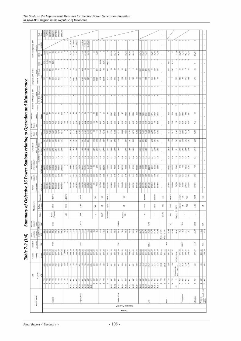
The Study on the Improvement Measures for Electric Power Generation Facilities in Java-Bali Region in the Republic of Indonesia
Com
mi-
Inst
alle
d (M
ax.)
Ava
ilabl
eA
vaila
ble
Cap
acity
Pow
er
Gro
ssC
apac
itySe
rvic
eH
ours
Serv
ice
Fact
orSt
and
by
ssio
ning
Cap
acity
Cap
acity
Tota
lG
ener
atio
nFa
ctor
Rat
eEf
ficie
ncy
(SH
)(S
F)(R
SH)
Out
age
by P
/Sby
Sys
tem
F.O
+M.O
MFO
HSD
NG
Coa
lyy
.mm
MW
MW
MW
MW
h/ye
ar
MW
h/ye
ar%
kcal
/kW
h%
Hou
rs%
Hou
rsK
LK
LM
MB
TUTo
n1
TU40
0.0
1985
.04
400.
02,
614,
863
0.74
164,
175
6.3
2,47
734
.77,
539
85.8
331
100
705
507
37,9
142,
486
1,24
2,03
42
TU40
0.0
1985
.06
400.
02,
113,
298
0.60
143,
084
6.8
2,36
336
.47,
829
89.1
286
112
00
668
31,8
604,
933
947,
391
3TU
400.
019
89.0
240
0.0
2,57
9,47
90.
7315
9,23
06.
22,
393
35.9
7,58
186
.377
14
097
515
113
,214
894
1,21
0,79
24
TU40
0.0
1989
.11
400.
02,
638,
923
0.75
166,
632
6.3
2,38
336
.17,
557
86.0
691
40
676
481
24,8
6082
31,
225,
349
5TU
600.
019
97.0
660
0.0
4,16
2,81
30.
7919
3,28
04.
62,
418
35.6
8,52
697
.156
14
019
012
094
62,
017,
561
6TU
600.
019
97.0
960
0.0
4,09
0,61
60.
7819
3,67
94.
72,
344
36.7
7,87
089
.656
12
180
936
088
11,
906,
130
7TU
600.
019
97.1
260
0.0
4,51
0,58
80.
8620
8,00
64.
62,
304
37.3
8,61
798
.115
80
10
08
048
32,
086,
743
3TU
50.0
(199
8)45
.00
00
--
-0
0.0
0-
--
00
00
04
TU50
.020
05.1
245
.00
00
--
-0
0.0
0-
--
00
00
0B
L1.1
GT
131.
419
94.0
912
5.0
653,
989
0.57
3,98
10.
63,
039
28.3
6,47
573
.722
43
02,
275
110
19,7
487,
249,
797
BL1
.2G
T13
1.4
1994
.09
125.
076
2,28
10.
6625
,083
3.3
2,91
929
.57,
311
83.2
382
60
1,41
024
083
,284
6,23
4,09
3B
L1.3
GT
131.
419
94.1
012
5.0
687,
426
0.60
23,1
793.
42,
898
29.7
6,40
172
.933
37
02,
118
232
027
,997
7,24
8,97
2B
L1.4
ST20
3.5
1994
.10
175.
01,
003,
749
0.56
2,62
90.
3-
-8,
781
100.
00
03
10
3-
BL2
.1G
T13
1.4
1994
.02
125.
070
9,58
00.
6124
,995
3.5
2,95
529
.17,
126
81.1
04
51
1,54
311
60
17,7
017,
997,
034
BL2
.2G
T13
1.4
1994
.02
125.
088
8,29
70.
7723
,178
2.6
2,90
229
.68,
289
94.4
584
41
423
140
141,
830
5,57
2,19
3B
L2.3
GT
131.
419
94.0
311
5.0
896,
215
0.78
4,44
70.
53,
032
28.4
8,55
597
.40
24
121
515
010
,948
10,4
27,8
85B
L2.4
ST20
3.5
1994
.12
160.
01,
186,
409
0.66
3,41
30.
3-
-8,
779
99.9
00
31
05
-1
GT
26.0
1976
.09
18.0
936
0.00
313.
34,
476
19.2
500.
652
10
08,
682
00
494
03
GT
26.0
1976
.02
18.0
7,66
20.
0328
43.
74,
339
19.8
411
4.7
4,55
42
50
3,52
629
30
3,88
70
1TU
50.0
1978
.09
45.0
312,
384
0.71
26,2
738.
42,
771
31.0
7,94
690
.56
14
166
416
893
,504
00
2TU
50.0
1978
.10
45.0
284,
422
0.65
22,2
317.
82,
797
30.7
7,61
886
.765
15
11,
043
5885
,962
00
3TU
200.
019
83.0
720
0.0
Mits
ui-R
iley
MH
IM
ELC
O1,
125,
718
0.64
71,5
496.
42,
387
36.0
7,98
390
.936
12
162
214
329
0,17
90
0
BL1
.1G
T10
9.7
1993
.08
105.
045
9,18
80.
485,
160
1.1
3,06
528
.15,
734
65.3
2,38
11
60
639
300
163,
286
0
BL1
.2G
T10
9.7
1993
.10
105.
043
2,69
20.
457,
003
1.6
3,09
027
.85,
455
62.1
2,71
31
50
589
270
155,
117
0
BL1
.3G
T10
9.7
1993
.10
105.
026
8,25
10.
288,
118
3.0
3,08
627
.93,
512
40.0
4,18
01
40
1,06
824
096
,035
0
BL1
.4ST
188.
019
97.1
117
0.0
568,
834
0.34
34,3
536.
0-
-8,
080
92.0
471
181
574
83-
--
BL2
.1G
T10
9.7
1996
.07
105.
039
2,89
60.
413,
172
0.8
2,99
628
.74,
921
56.0
3,30
21
40
387
175
013
6,56
30
BL2
.2G
T10
9.7
1996
.08
105.
043
3,39
50.
452,
995
0.7
2,99
728
.75,
241
59.7
3,38
61
10
155
20
150,
693
0
BL2
.3G
T10
9.7
1996
.09
105.
042
3,61
10.
442,
586
0.6
3,05
528
.26,
079
69.2
2,38
61
30
317
20
150,
101
0
BL2
.4ST
188.
019
97.0
517
0.0
577,
928
0.35
50,1
118.
7-
-8,
492
96.7
169
012
146
77-
--
BL1
.1G
T11
2.45
1996
.10
100.
7518
6,82
00.
193,
126
1.7
3,29
226
.12,
630
29.9
3,94
21
20
476
1,73
70
69,7
160
BL1
.2G
T11
2.45
1996
.10
100.
7522
9,07
00.
233,
377
1.5
3,39
425
.33,
423
39.0
5,13
90
140
022
20
87,5
970
BL1
.3G
T11
2.45
1996
.10
100.
7525
0,63
00.
253,
902
1.6
3,40
925
.23,
468
39.5
4,61
11
80
572
133
094
,413
0B
L1.4
ST18
9.50
1997
.03
159.
5827
5,91
00.
1722
,234
8.1
--
4,05
046
.12,
800
010
00
1,93
4-
--
BL2
1G
T11
3.84
2002
.10
101.
9014
2,56
00.
142,
979
2.1
3,65
923
.52,
209
25.1
6,39
61
30
106
730
55,8
240
BL2
2G
T11
3.84
2002
.10
101.
9010
5,35
00.
112,
372
2.3
3,39
925
.31,
575
17.9
6,36
71
90
114
729
039
,916
0B
L2 3
GT
113.
8420
02.1
010
1.90
117,
150
0.12
2,56
52.
23,
423
25.1
1,78
320
.36,
568
110
088
345
044
,495
0
1TU
(25.
0)19
64.x
x-
--
--
--
--
--
--
--
--
-
2TU
(25.
0)19
64.x
x-
--
--
--
--
--
--
--
--
-
3TU
50.0
1978
.04
45.0
023
1,19
60.
5314
,912
6.4
3,01
028
.67,
817
89.0
312
08
00
655
69,1
1811
80
4TU
50.0
1978
.07
45.0
020
4,88
40.
4713
,900
6.8
3,09
927
.87,
017
79.9
520
05
00
1,24
761
,128
430
1~11
D5.
08 x
4 +
4.14
+6.
77x 2
+ 6
.52
x 219
73.0
2~19
89.0
260
.91
70,5
340.
123,
848
5.5
2,51
134
.21,
561
17.8
6,95
13.
71
727
21
019
,106
0
1G
T21
.35
1985
.02
19.5
Alst
omA
lstom
54,8
750.
2964
21.
23,
885
22.1
3,13
135
.65,
017
42
061
818
022
,996
02
GT
20.1
019
93.0
518
.0G
EG
E35
,625
0.20
432
1.2
3,94
621
.82,
067
23.5
6,58
89
10
5871
015
,163
03
GT
42.0
019
94.0
737
.126
9,66
10.
733,
532
1.3
3,40
825
.28,
216
93.5
332
32
214
09
099
,111
04
GT
42.0
019
94.0
735
.123
2,63
30.
632,
212
1.0
3,39
525
.37,
225
82.3
611
45
091
533
085
,197
0
Gilim
anuk
1G
T13
3.8
1997
.07
133.
813
3.80
133.
8-
AB
BA
BB
707,
391
0.60
494
0.1
3,31
026
.08,
389
95.5
186
40
346
310
256,
854
0
1G
T48
.820
04.1
145
.0-
--
--
--
--
--
--
--
--
-
2G
T48
.820
05.1
045
.0-
--
--
--
--
--
--
--
--
-
Thermal
170.
61
Fuel
Con
sum
ptio
n in
200
4
Fue
l Typ
e
MH
I
WH
GE
-
Mirr
lees
BS,
SW
D
3,40
0
Aus
trian
-EE -
CM
I
Retir
ed in
199
6
B&
W(C
anad
a)
(F&
W)
90 90.0
Stat
ion
Use
(PS
+ SU
SUT
TRA
FO)
Gro
ss H
eat
(GE)
Boi
ler
-
GE
AB
B
GE
MH
I
100.
0
MH
IM
HI
F&W
WH
AB
B
MH
I
Retir
ed in
199
6
Pesa
ngga
ran
Gra
ti
3,40
0
1347
.4
Tam
bak
Loro
k
Sura
laya
Tanj
ung
Prio
k
1334
.2
Pera
k
Pem
aron
*com
ing
from
T. P
riok
in 2
002.
97.6
201.
27
Indonesia Power (IP)Pow
er S
tatio
n
No.
of t
imes
as o
f Nov
embe
r 200
5C
apac
ity
Uni
t
MW
Out
gae
Hou
rs
Num
ber o
f Out
ages
in 2
004
Out
ages
in 2
004
by P
/S
868.
37
1,20
1.0
1260
.00
-M
HI
MH
I
767.
5
(GE)
AB
B
GE
MEL
CO
Turb
ine
/R
unne
r
Siem
ens
Plan
ned
Plan
ned
in 2
004
(PH
= 8
,784
Hou
rs)
Gen
erat
or
Man
ufac
ture
r MEL
CO
WH
MEL
CO
WH
GE
GE
Siem
ens
Tabl
e 7-
2 (1
/4)
Su
mm
ary
of O
bjec
tive
16 P
ower
Sta
tions
rela
ting
to O
pera
tion
and
Mai
nten
ance
Final Report < Summary > - 108 -

The Study on the Improvement Measures for Electric Power Generation Facilities in Java-Bali Region in the Republic of Indonesia
C
omm
i-In
stal
led
(Max
.)A
vaila
ble
Ava
ilabl
eC
apac
ityPo
wer
G
ross
Cap
acity
Serv
ice
Hou
rsSe
rvic
eFa
ctor
Stan
d by
ssio
ning
Cap
acity
Cap
acity
Tota
lG
ener
atio
nFa
ctor
Rat
eEf
ficie
ncy
(SH
)(S
F)(R
SH)
Out
age
by P
/Sby
Sys
tem
F.O
+M.O
MFO
HSD
NG
Coa
lyy
.mm
MW
MW
MW
MW
h/ye
ar
MW
h/ye
ar%
kcal
/kW
h%
Hou
rs%
Hou
rsK
LK
LM
MB
TUTo
n1
TU10
0.0
1979
.02
90.0
604,
005
0.69
39,8
546.
62,
822
30.5
8,18
093
.125
08
10
579
167,
490
870
2TU
100.
019
79.0
290
.055
8,99
00.
6431
,995
5.7
2,84
930
.27,
570
86.2
143
012
00
1,07
116
9,06
552
03
TU10
0.0
1979
.06
90.0
491,
665
0.56
31,2
346.
42,
887
29.8
6,49
674
.010
6?
70
1,21
796
514
9,03
251
04
TU20
0.0
1981
.11
190.
055
7,55
40.
3256
,433
10.1
2,64
832
.57,
715
87.8
330
81
01,
035
165,
032
624
4,59
4,19
55
TU20
0.0
1982
.06
190.
066
6,33
20.
3843
,731
6.6
2,61
332
.96,
389
72.7
0?
171
1,31
31,
082
185,
188
1,28
31,
427,
452
BL1
.1G
T10
7.8
1993
.10
103.
066
1,03
60.
7077
90.
13,
256
26.4
7,21
282
.110
012
30
1,56
20
08,
429,
573
BL1
.2G
T10
7.8
1993
.xx
103.
036
6,30
70.
3968
40.
23,
788
22.7
5,78
065
.836
?20
22,
233
736
00
5,11
5,22
1B
L1.3
GT
107.
819
93.x
x10
3.0
524,
762
0.55
745
0.1
3,17
827
.15,
772
65.7
0?
42
988
2,02
40
06,
593,
872
BL1
.4ST
185.
019
95.x
x16
0.0
586,
954
0.36
46,3
617.
9-
-8,
131
92.6
00
113
065
2-
--
1TU
100.
019
81.0
895
.061
9,31
7
0.71
36,0
555.
82,
652
32.4
8,77
199
.90
01
00
1316
7,68
90
02
TU10
0.0
1981
.11
95.0
596,
256
0.
6834
,021
5.7
2,68
732
.08,
339
94.9
01
10
289
156
103,
506
00
3TU
200.
019
88.0
320
0.0
986,
821
0.
5661
,425
6.2
2,40
435
.87,
790
88.7
01
11
850
143
168,
360
02,
863,
878
4TU
200.
019
88.0
720
0.0
1,02
3,17
7
0.
5864
,420
6.3
2,40
635
.77,
953
90.5
02
11
701
129
191,
129
02,
333,
800
BL1
.1G
T11
2.45
1992
.03
100.
070
4,69
0
0.71
4,60
30.
73,
390
25.4
8,36
195
.26
21
121
320
40
09,
480,
435
BL1
.2G
T11
2.45
1992
.05
100.
072
0,79
0
0.73
4,16
90.
63,
394
25.3
8,52
497
.019
12
221
230
00
9,70
8,53
6B
L1.3
GT
112.
4519
92.0
610
0.0
715,
810
0.
734,
177
0.6
3,35
025
.78,
443
96.1
181
41
242
800
09,
514,
354
BL1
.4ST
188.
9119
93.0
417
0.0
1,29
2,89
0
0.
7838
,321
3.0
--
8,48
796
.60
14
228
313
--
-B
L2.1
GT
112.
4519
92.0
710
0.0
482,
250
0.
493,
152
0.7
3,58
724
.07,
447
84.8
233
16
091
419
00
190,
062
172
BL2
.2G
T11
2.45
1992
.08
100.
051
2,01
0
0.52
3,74
90.
73,
605
23.9
7,95
290
.530
31
30
211
318
019
9,71
011
3,46
1B
L2.3
GT
112.
4519
92.0
910
0.0
429,
120
0.
432,
790
0.7
3,64
423
.66,
866
78.2
667
311
196
029
10
171,
741
172
BL2
.4ST
188.
9119
93.0
817
0.0
859,
730
0.
5234
,961
4.1
--
8,76
199
.720
00
10
2-
--
BL3
.1G
T11
2.45
1993
.01
105.
052
9,90
0
0.54
3,11
50.
63,
681
23.4
7,90
590
.024
31
11
585
520
07,
740,
848
BL3
.2G
T11
2.45
1993
.01
105.
050
7,95
0
0.51
2,54
30.
53,
640
23.6
7,45
884
.945
51
01
780
910
07,
338,
347
BL3
.3G
T11
2.45
1993
.01
105.
054
2,07
0
0.55
4,09
40.
83,
579
24.0
7,70
987
.819
01
11
864
210
07,
698,
444
BL3
.4ST
188.
9119
93.1
118
0.0
978,
140
0.
5934
,454
3.5
--
7,93
990
.40
12
283
212
--
-1
GT
20.1
1978
.06
17.0
Alst
omA
lstom
6,94
9
0.
0416
52.
44,
488
19.2
464
5.3
7,30
80
30
01,
012
03,
439
02
GT
20.1
1978
.06
17.0
Alst
omA
lstom
8,98
4
0.
0519
42.
23,
863
22.3
520
5.9
7,59
71
60
513
153
03,
820
03
GT
(20.
1)19
84.0
8To
Sum
atra
-A
lstom
Alst
om-
--
--
--
--
--
--
--
--
1*G
T20
.119
99.1
016
.5G
E7,
830
0.04
218
2.8
4,20
820
.449
05.
67,
581
12
057
014
30
3,63
90
2*G
T20
.119
99.1
116
.5G
E9,
355
0.05
216
2.3
4,25
120
.259
06.
77,
866
01
00
328
04,
386
0
1TU
400.
019
94.0
440
0.0
2,74
9,48
70.
7819
4,82
87.
12,
614
32.9
7,69
187
.615
51
60
662
276
01,
100
1,39
6,58
0
2TU
400.
019
93.1
140
0.0
2,75
1,94
80.
7819
1,40
17.
02,
575
33.4
7,76
288
.410
61
50
624
292
01,
021
1,37
5,49
7
BL1
.1G
T14
5.0
1997
.01
133.
865
4,60
10.
515,
460
0.80
3,20
226
.96,
780
77.2
870
33
11,
032
102
022
5,80
90
BL1
.2G
T14
5.0
1997
.03
133.
863
5,21
10.
505,
072
0.80
3,17
327
.16,
393
72.8
760
25
065
997
10
217,
263
0B
L1.3
GT
145.
019
97.0
413
3.8
649,
435
0.51
5,15
60.
803,
163
27.2
6,61
375
.399
92
11
474
698
022
1,46
80
BL1
.4ST
225.
019
97.1
020
2.0
1,01
8,43
10.
5281
,747
8.00
--
8,14
692
.761
40
41
023
--
-2.
1G
T14
5.0
1997
.03
133.
870
,475
0.06
1,17
11.
703,
112
27.6
707
8.0
150
10
02,
147
5,78
00
23,4
890
2.2
GT
145.
019
97.0
613
3.8
102,
349
0.08
1,20
71.
203,
295
26.1
1,18
013
.458
31
30
6,55
147
10
36,1
030
2.3
GT
(145
.0)
--
--
--
--
--
--
--
--
--
1-
175.
1819
85.1
017
5.18
586,
933
0.40
4,76
354
.23,
862
13
154
52
-17
5.18
1985
.11
175.
1856
0,78
90.
404,
773
54.3
3,87
91
512
84
3-
175.
1819
86.0
417
5.18
337,
063
0.20
2,62
829
.94,
091
18
2,02
045
4-
175.
1819
86.0
517
5.18
505,
703
0.30
4,18
447
.62,
232
45
2,33
434
1-
60.3
1988
.11
60.3
155,
354
0.30
982.
20.
63,
420
38.9
5,23
51
012
90
2-
60.3
1988
.11
60.3
131,
602
0.20
815.
60.
62,
949
33.6
5,71
81
410
89
3-
60.3
1988
.11
60.3
150,
825
0.30
932.
40.
63,
342
38.0
5,18
81
324
86
1-
126.
019
88.0
512
6.0
142,
472
0.10
1,82
620
.86,
487
21
466
52
-12
6.0
1988
.02
126.
013
9,42
80.
101,
799
20.5
6,20
91
177
51
3-
126.
019
88.0
912
6.0
168,
325
0.20
2,10
023
.95,
173
33
1,48
823
4-
126.
019
88.0
812
6.0
119,
375
0.10
1,76
220
.17,
022
00
00
5-
126.
019
97.0
812
6.0
165,
839
0.10
5,40
3 (2
005)
0.4
(200
5)2,
300
26.2
6,21
11
027
30
6-
126.
019
97.0
812
6.0
138,
285
0.10
1,92
621
.96,
501
13
348
97
-12
6.0
1998
.04
126.
013
3,87
00.
101,
828
20.8
5,92
31
11,
032
18
-12
6.0
1998
.04
126.
012
5,30
80.
101,
748
19.9
6,37
11
165
015
1-
35.0
1973
.xx
35.0
149,
702
0.50
5,69
964
.92,
965.
00
120
02
-35
.019
73.x
x35
.017
0,99
90.
6063
6 (2
005)
0.2
(200
5)6,
562
74.7
2,12
6.0
096
03
-35
.019
73.x
x35
.013
0,35
60.
404,
383
49.9
3,65
7.0
074
40
Not
e:(1
)O
utag
e ho
urs
= F.
O(F
orce
d O
utag
e) h
ours
+ M
.O.
(Mai
nten
ance
Out
age)
hou
rs
Gen
erat
orM
W
Plan
ned
in 2
004
(PH
= 8
,784
Hou
rs)
Pow
er S
tatio
n
Uni
t M
anuf
actu
rer
Cap
acity
as o
f Nov
embe
r 200
5B
oile
rTu
rbin
e /
Run
ner
IHI
Fuel
Con
sum
ptio
n in
200
4
Fue
l Typ
e
No.
of t
imes
Hou
rs
Stat
ion
Use
(PS
+ SU
SUT
TRA
FO
Tabl
e 7-
2 (2
/4)
Su
mm
ary
of O
bjec
tive
16 P
ower
Sta
tions
rela
ting
to O
pera
tion
and
Mai
nten
ance
)
Gro
ss H
eat
Num
ber o
f Out
ages
in 2
004
Out
ages
in 2
004
by P
/S
Plan
ned
5,52
90.
3
-M
HI
Out
gae
1119
.0
Aus
trian
EE
MH
I
MH
I
GE
Tosh
iba
Tosh
iba
Tosh
iba
-
MH
I
-
B&
W
Tosh
iba
BO
VIN
G
AB
B
-
AB
B
Voe
stA
ppin
e H
G
180.
9
Paito
n80
0.0
Mua
ra K
aran
g12
08.4
* m
eans
Gili
timur
P/S
in M
adur
a
Gre
sik
Hydro
IP PJBPJB
Thermal
Mov
e to
Gili
man
uk in
199
7
2,25
9.2
Mua
ra T
awar
950.
0
Suta
mi
105.
0
Sudi
rman
(Soe
dirm
an)
180.
9
Cira
ta10
08.0
Sagu
ling
700.
72
105.
0
1008
.0
871.
0
Com
butio
nEn
g. U
SA80
0.0
Tosh
iba
700.
72
2092
.0
AB
B
GE
Tosh
iba
MEL
CO
Tosh
iba
MEL
CO
ASE
A
ELIN
MEL
CO
- 109 - Final Report < Summary >

The Study on the Improvement Measures for Electric Power Generation Facilities in Java-Bali Region in the Republic of Indonesia
Com
mi-
ssio
ning
yy.m
m1
TU40
0.0
1985
.04
2TU
400.
019
85.0
63
TU40
0.0
1989
.02
4TU
400.
019
89.1
15
TU60
0.0
1997
.06
6TU
600.
019
97.0
97
TU60
0.0
1997
.12
3TU
50.0
(199
8)4
TU50
.020
05.1
2B
L1.1
GT
131.
419
94.0
9B
L1.2
GT
131.
419
94.0
9B
L1.3
GT
131.
419
94.1
0B
L1.4
ST20
3.5
1994
.10
BL2
.1G
T13
1.4
1994
.02
BL2
.2G
T13
1.4
1994
.02
BL2
.3G
T13
1.4
1994
.03
BL2
.4ST
203.
519
94.1
21
GT
26.0
1976
.09
3G
T26
.019
76.0
2
1TU
50.0
1978
.09
2TU
50.0
1978
.10
3TU
200.
019
83.0
7
BL1
.1G
T10
9.7
1993
.08
BL1
.2G
T10
9.7
1993
.10
BL1
.3G
T10
9.7
1993
.10
BL1
.4ST
188.
019
97.1
1
BL2
.1G
T10
9.7
1996
.07
BL2
.2G
T10
9.7
1996
.08
BL2
.3G
T10
9.7
1996
.09
BL2
.4ST
188.
019
97.0
5
BL1
.1G
T11
2.45
1996
.10
BL1
.2G
T11
2.45
1996
.10
BL1
.3G
T11
2.45
1996
.10
BL1
.4ST
189.
5019
97.0
3B
L2 1
GT
113.
8420
02.1
0B
L2 2
GT
113.
8420
02.1
0B
L2 3
GT
113.
8420
02.1
0
1TU
(25.
0)19
64.x
x
2TU
(25.
0)19
64.x
x
3TU
50.0
1978
.04
4TU
50.0
1978
.07
1~11
D5.
08 x
4 +
4.1
4+
6.77
x 2
+ 6.
52x
2 +1
2.39
x 2
1973
.02
~198
9.02
1G
T21
.35
1985
.02
2G
T20
.10
1993
.05
3G
T42
.00
1994
.07
4G
T42
.00
1994
.07
Gilim
anuk
1G
T13
3.8
1997
.07
(1) C
.C. c
onve
rsio
n of
PLT
G ga
s tu
rbin
e (1
-1-1
)(2
) C.C
. con
vers
ion
of P
LTG
(1-1
-1) a
nd s
hotd
own
ofex
istin
g Pe
sang
gara
n PL
TG #
1 &
#2
(UBP
Bal
i)
1G
T48
.820
04.1
1
2G
T48
.820
05.1
0
(1) C
.C. c
onve
rsio
n of
PLT
U #
1 an
d #2
(1-1
-2)
(2) N
ew C
.C. p
lant
con
sist
ing
of la
rge
GT (1
-1-2
) and
shut
dow
n of
the
exis
ting
Suny
arag
i PLT
G #
1 to
#4
and
Cila
cap
PLTG
#1
and
#2 (O
il Re
duct
ion
Plan
as
UBP
Sem
aran
g)
(1) C
.C. c
onve
rsio
n of
PLT
G Bl
ock
2 (3
-3-1
)(2
) C.C
. con
vers
ion
of P
LTG
Bloc
k 2
(3-3
-1) a
ndsh
utdo
wn
of th
e ex
istin
g Pe
rak
PLTU
#3
& #
4 (O
ilRe
duct
ion
Plan
as
UBP
Per
ak/G
rati)
Dev
elop
men
t of B
L3 fo
r Com
bine
d Cy
cle
(PLT
GU) b
yIP
P fo
rmat
ion
Uni
t
MW
Cap
acity
Non
e
No
Repo
wer
ing
Plan
due
to e
nviro
nmen
tal
cons
erva
tion
of m
angr
ove
at s
eash
ore
Pow
er S
tatio
n
Tam
bak
Loro
k
Sura
laya
Tanj
ung
Prio
k
Indonesia Power (IP)
Thermal
Pesa
ngga
ran
Gra
ti
Pera
k
Pem
aron
*com
ing
from
T. P
riok
in 2
002.
Mod
erni
zatio
n pr
ojec
t for
Pes
angg
aran
Pow
er S
tatio
n(J
BIC,
12/
28/2
005
Adv
ertis
emen
t)- N
ew c
onst
ruct
ion
of D
ME
(dim
ethy
l eth
er)-f
ired
com
bine
d cy
cle
pla
nt
Conv
ersi
on to
PLG
TU b
y ad
ding
one
GT
and
one
HRS
G to
exis
ting
TU3
& T
U4
(1-1
-2)
Con
vers
ion
to P
LTG
U +
50
MW
,lis
ted
in R
UK
N (
IP O
wn
Bud
get)
Sem
aran
g Po
wer
Pla
ntRe
habi
litat
ion
and
Gasi
ficat
ion
Proj
ect (
for U
nit 3
) (J
BIC
Yen
Loan
)
Con
vert
ion
to P
LTG
U +
720
MW
(JB
IC Y
en L
oan)
- Add
ition
of t
hree
gas
turb
ines
Mai
n R
ehab
ilitat
ion,
Mod
ifica
tion
and
Upr
atin
g W
orks
The
reha
bilit
atio
n pr
ojec
t for
PLT
U U
nit 3
and
4 (J
BIC
Yen
Loan
; 19
91.0
8 ~
1994
. 09)
- Boi
ler :
repl
acem
ent o
f Hea
ter,
nozz
le, a
nd a
ir he
ater
,et
c.- T
urbi
ne: o
verh
aul o
f bla
de, C
WP,
con
dens
er tu
be,
etc.
- Ele
ctric
al a
nd C
ontro
l Sys
tem
: ov
erha
ul- M
oder
Boi
ler -
Rel
ated
Oth
ers
Turb
ine-
Rel
ated
Rem
aini
ng L
ife A
sses
smen
t&
Perf
orm
ance
Ass
essm
ent
Tan
jung
Per
ak H
arbo
r, Su
raba
ya, I
ndon
esia
Pera
k T
herm
al P
lant
# 3
& 4
The
rmal
Per
form
ance
Tes
t Rep
ort
(200
5. 1
0. K
orea
Ele
ctric
Pow
er R
esea
rch
Inst
itute
)
Life
Tim
e A
sses
smen
t of C
onde
nser
Tub
e,Bo
iler U
nit 3
A&
B(2
004.
05, P
T. S
uper
inte
ndin
g Co
mpa
ny o
fIn
done
sia
Engi
neer
ing
and
Tran
sfor
mat
ion
(SU
COFI
ND
O))
Rem
aini
ng L
ife A
sses
smen
t Boi
ler U
nit-2
PLT
UTa
mba
k Lo
rok
UBP
Sem
aran
gN
o. 0
56.B
KIT
.097
A.2
004
(200
4.0
Boile
r Rem
aini
ng L
ife A
sses
smen
t (BR
LA)
No.
073.
BKIT
.007
E.20
04U
nit -
1 U
BP S
URA
LAY
A(2
004,
LIT
BAN
G)Li
fe E
xten
sion
for S
ural
aya,
Pre
limin
ary
Boile
rIn
spec
tion
for U
nit 2
(199
8.01
, Bab
cock
& W
ilcox
Inte
rnat
iona
l, In
c.)
Sura
laya
Ste
am P
ower
Pla
nt U
nit-
2,
Reh
abilit
atio
n, M
odifi
catio
n &
Rep
ower
ing
Plan
as
of 2
005.
12
Fina
l Pro
posa
l by
JIC
A S
TUD
Y T
eam
Non
e
Non
e
Und
er P
repa
ratio
n an
d Fu
ture
Pla
nA
lread
y C
omm
itted
#1 ~
#4
Rep
lace
men
t of s
econ
dary
sup
erhe
ater
& re
heat
er o
utle
t,pr
imar
y &
sec
onda
ry a
ir he
ater
bas
ket,
seal
and
fan
adju
stm
ent a
nd H
IP tu
rbin
e. In
spec
tion
mai
n co
nden
ser,
dear
ator
& H
P fe
ed w
ater
. Rew
indi
ng g
ener
ator
sta
tor &
rote
r. R
enew
al o
f bru
shle
ss e
Non
e
Ta
ble
7-2
(3/4
)
Sum
mar
y of
Obj
ectiv
e 16
Pow
er S
tatio
ns re
latin
g to
Ope
ratio
n an
d M
aint
enan
ce
Final Report < Summary > - 110 -

The Study on the Improvement Measures for Electric Power Generation Facilities in Java-Bali Region in the Republic of Indonesia
Com
mi-
ssio
ning
yy.m
m1
TU10
0.0
1979
.02
2TU
100.
019
79.0
23
TU10
0.0
1979
.06
4TU
200.
019
81.1
15
TU20
0.0
1982
.06
BL1
.1G
T10
7.8
1993
.10
BL1
.2G
T10
7.8
1993
.xx
BL1
.3G
T10
7.8
1993
.xx
BL1
.4ST
185.
019
95.x
x1
TU10
0.0
1981
.08
2TU
100.
019
81.1
13
TU20
0.0
1988
.03
4TU
200.
019
88.0
7B
L1.1
GT
112.
4519
92.0
3B
L1.2
GT
112.
4519
92.0
5B
L1.3
GT
112.
4519
92.0
6B
L1.4
ST18
8.91
1993
.04
BL2
.1G
T11
2.45
1992
.07
BL2
.2G
T11
2.45
1992
.08
BL2
.3G
T11
2.45
1992
.09
BL2
.4ST
188.
9119
93.0
8B
L3.1
GT
112.
4519
93.0
1B
L3.2
GT
112.
4519
93.0
1B
L3.3
GT
112.
4519
93.0
1B
L3.4
ST18
8.91
1993
.11
1G
T20
.10
1978
.06
2G
T20
.10
1978
.06
3G
T(2
0.1)
1984
.08
1*G
T20
.10
1999
.10
2*G
T20
.10
1999
.11
1TU
400.
019
94.0
4
2TU
400.
019
93.1
1
BL1
.1G
T14
5.0
1997
.01
BL1
.2G
T14
5.0
1997
.03
BL1
.3G
T14
5.0
1997
.04
BL1
.4ST
225.
019
97.1
02.
1G
T14
5.0
1997
.03
2.2
GT
145.
019
97.0
6
2.3
GT
(145
.0)
Mov
e to
Gili
man
uk in
1997
1-
175.
1819
85.1
02
-17
5.18
1985
.11
3-
175.
1819
86.0
44
-17
5.18
1986
.05
1-
60.3
1988
.11
2-
60.3
1988
.11
3-
60.3
1988
.11
1-
126.
019
88.0
52
-12
6.0
1988
.02
3-
126.
019
88.0
94
-12
6.0
1988
.08
5-
126.
019
97.0
86
-12
6.0
1997
.08
7-
126.
019
98.0
48
-12
6.0
1998
.04
1-
35.0
1973
.xx
2-
35.0
1973
.xx
3-
35.0
1973
.xx
Not
e:(1
)O
utag
e ho
urs
= F.
O(F
orce
d O
utag
e) h
ours
+ M
.O.
(Mai
nten
ance
Out
age)
hou
rs
Und
er P
repa
ratio
n an
d Fu
ture
Pla
nFi
nal P
ropo
sal b
y JI
CA
STU
DY
Tea
mB
oile
r - R
elat
ed
Uni
t R
ehab
ilitat
ion,
Mod
ifica
tion
& R
epow
erin
g Pl
an a
s of
200
5.12
MW
Cap
acity
The
proj
ect f
or re
habi
litat
ion
of G
resi
k St
eam
Pow
er P
lant
Uni
t 1 a
nd 2
(Jap
an's
OD
A g
rant
;19
99 ~
2000
)
- Ef
ficie
ncy
reco
very
(re
plac
emen
t of t
urbi
nebl
ade)
The
proj
ect f
or re
habi
litat
ion
of G
resi
k St
eam
Pow
er P
lant
Uni
t 3 a
nd 4
(Jap
an's
OD
A g
rant
;20
05 ~
2006
)
- Fu
el c
onve
rsio
n fro
m M
FO to
Gas
for
Boile
rs
+GT2
.2 R
epla
cem
ent o
f Noz
le N
o. 1
0, 1
1, 1
5 an
d16
(04.
06)
+GT1
.2 R
epla
cem
ent o
f Fue
l Gas
No
Mai
n R
ehab
ilitat
ion,
Mod
ifica
tion
and
Upr
atin
g W
orks
Turb
ine-
Rel
ated
The
proj
ect f
or re
habi
litat
ion
of G
resi
k St
eam
Pow
erPl
ant U
nit 1
and
2 (J
apan
's O
DA
gra
nt ;
1999
~20
00)
-
Fuel
con
vers
ion
from
MFO
to G
as f
or B
oile
rs
The
proj
ect f
or re
habi
litat
ion
of G
resi
k St
eam
Pow
erPl
ant U
nit 3
and
4 (J
apan
's O
DA
gra
nt ;
2005
~20
06)
-
Fuel
con
vers
ion
from
MFO
to G
as f
or B
oile
rs
The
fuel
con
vers
ion
proj
ect f
or U
nit 3
and
4 (J
BIC
Yen
Loan
; 199
1.05
~ 1
994.
08)
- Ins
talla
tion
of
+GT1
.1 C
hem
ical
Cle
anin
g an
d Re
-bal
anci
ngof
Com
pres
sor (
04.0
1)+H
RSG3
.3 W
eldi
ng a
t lek
age
porti
on in
Supe
rhea
ter (
03.0
6)
+TU
#3
Repl
acem
ent o
f Fue
l oil
pum
pbe
arin
g (0
4.02
)
Stea
m tu
rbin
e, c
onde
nser
& p
umps
, gen
erat
or, e
xcite
ran
d tra
nsfo
rmer
s, b
oler
for T
U 4
& T
U5
(JBI
C Ex
port
Cred
it)
+GT
#1.1
Rep
lace
men
t of 1
st s
tage
noz
le&
buc
ker (
04.0
9)+G
T #1
.2 R
epla
cem
ent o
f cou
plin
g bo
lts &
exite
r (00
.04)
Non
e
Impr
ove
relia
bilit
y an
d av
aila
bilit
y Bo
iler,
Maj
or v
alve
and
turb
ine
acce
ssor
ies.
Impr
ove
effic
ienc
y, re
liabi
lity
and
life
exte
nsio
n of
ste
am tu
rbin
e. L
ife A
sess
men
t of
Gene
rato
r (JB
IC E
xpor
t Cre
dit)
New
con
stru
ctio
n of
BL
5 as
PLT
GU
+ 22
5 M
W(J
BIC
Yen
Loa
n)
+TU
#1
Repl
acem
ent o
f SH
& E
cono
mize
r tub
e (0
4.05
)+T
U #
1 Re
plac
emen
t of B
oile
r tub
e (0
4.02
)+T
U #
3 Re
plac
emen
t of A
H e
lem
ent(0
4.10
)+T
U #
3 Re
plac
emen
t of B
oile
r wal
l tub
e (0
4.06
)+T
U #
4 Re
plac
emen
t & w
eldi
ng o
f Eco
nom
izer t
ube
(04.
12)
+TU
#5
Repl
acem
ent
Oth
ers
Sagu
ling
Mua
ra T
awar
Suta
mi
Sudi
rman
(Soe
dirm
an)
Cira
ta
Rep
lace
men
t of t
urbi
ne ru
nner
& a
cces
sorie
s an
d go
vern
orsy
stem
(JB
IC E
xpor
t Cre
dit)
(200
6~)
- Rep
lace
men
t to
new
turb
ine
runn
er (u
prat
ing 2
%)
- Rep
lace
men
t of g
uide
val
ve, g
oven
or s
yste
m a
nd c
oolin
gsy
stem
Mod
ifica
tion
of C
ontr
ol P
anel
Sys
tem
(Int
egra
tion
of e
ach
cont
rol s
yste
m) (
2006
) (PJ
B O
wn
Budg
et)
Hydro
IP PJBPJBPow
er S
tatio
n
Thermal
Rep
lace
men
t of e
mbe
ded
pipe
coo
ling
syst
em (2
006
~ 07
)(P
JB O
wn
Bud
get)
Cira
ta C
ontr
ol P
anel
sys
tem
mod
ifica
tion
(SC
AD
A) (
2006
~ 07
) (PJ
B O
wn
Bud
get)
Mua
ra K
aran
gCo
nver
sion
to P
LTGU
for T
U 1
~3(2
-2-3
), +
720
MW
(JBI
C Ye
nLo
an)
* m
eans
Gili
timur
P/S
in M
adur
a
Gre
sik
Paito
n
Mod
ifica
tion
of C
ontr
ol S
yste
m fo
r Gas
Tur
bine
Ope
nC
ycle
(200
6) (P
JB O
wn
Bud
get)
Con
vers
ion
to c
ombi
ned
cycl
e pl
ant f
or G
T1
and
GT
2(E
xpec
ting
JBIC
yen
loan
)
Alre
ady
Com
mitt
ed
Site
Inve
stig
atio
n R
epor
t for
Pre
sent
Sta
tus
ofEl
ectr
o-M
echa
nica
l Equ
ipm
ent f
or S
utam
iH
ydro
pow
er S
tatio
n(2
004.
12, N
ippo
n K
oei C
o., L
td.)
Infra
red
Ther
mog
raph
y In
spec
tion
Repo
rt us
ing
Ther
maC
AM
PM
-595
FLI
R Sy
stem
s (2
002.
11,
Don
ny G
UST
IAN
)
Rem
aini
ng L
fe A
sses
smen
t of B
oile
r #4
& #
5N
o.18
9.BK
IT.4
21A
.200
4(2
004,
LIT
BAN
G)
Lapo
ran
Has
il Pe
ngka
jian
Sisa
Um
ur, S
team
Biol
er P
ower
Pla
nt U
nit I
, PT.
PJB
II U
P. G
RESI
K(2
004,
PT
SURV
EYO
R IN
DO
NES
IA)
Lapo
ran
Has
il Pe
ngka
jian
Sisa
Um
ur, S
team
Biol
er P
ower
Pla
nt U
nit I
I, PT
. PJB
II U
P.GR
ESIK
(200
4, P
T SU
RVEY
OR
IND
ON
ESIA
)
Rem
ai
Stea
m T
urbi
ne In
spec
tion
Repo
rt on
Pai
ton
Pow
er S
tatio
n U
nit 1
and
2 (2
004.
08, T
oshi
ba)
Insp
ectio
n Re
port
Boile
r Pai
ton
Uni
t 1, 2
(200
4.07
, Tos
hiba
)Bo
iler R
emai
ning
Life
Ass
essm
ent (
BRLA
) PLU
Paito
n U
NIT
1 (2
005.
09 L
ITBA
NG)
Rem
aini
ng L
ife A
sses
smen
t&
Perf
orm
ance
Ass
essm
ent
(1) M
odifc
atio
n of
coo
ling
wat
er s
yste
m fr
om o
pene
d ty
peto
clo
sed
type
incl
udin
g cl
eani
ng a
nd li
ning
of e
mbe
ded
pipe
(2) R
epla
cem
ent o
f mon
itorin
g pa
nel a
nd c
ontr
ol c
ompu
ter
syst
em fo
r pow
er s
tatio
n
(1) R
epla
cem
ent o
f 154
kV
Circ
uit B
reak
er(2
) Rel
ocat
ion
of o
il co
oler
from
insi
de o
f the
gene
rato
r hou
sing
to o
utsi
de o
f the
gen
erat
orho
usin
g
Non
e
Non
e
Non
e
(1)R
epal
cem
ent o
f the
gen
erat
or a
nd b
earin
g co
oler
's tu
bem
ater
ial t
o an
ti co
rros
in ty
pe.
(2) R
epla
cem
ent o
f con
trol
ele
ctric
par
ts fo
r au
tom
atic
volta
ge c
ontr
ol s
yste
m a
nd g
over
nor
(3) R
epal
cem
ent o
f mon
itorin
g pa
nnel
in c
ontr
ol ro
om
(1) R
epla
cem
ent o
f con
trol e
lect
ric p
arts
for a
utom
atic
volta
ge c
ontro
l sys
tem
and
gov
erno
r(2
) Rep
lace
men
t of c
ontro
l ele
ctric
par
ts fo
r pow
erst
atio
n co
mpu
ter s
yste
m
Tabl
e 7-
2 (4
/4)
Su
mm
ary
of O
bjec
tive
16 P
ower
Sta
tions
rela
ting
to O
pera
tion
and
Mai
nten
ance
- 111 - Final Report < Summary >