Global SCADA Market in the Oil and Gas Industry 2016 to 2020

11-004CR (3)SAD
THE STUDY ON
GAS SCADA SYSTEM REHABILITATION AND EXPANSION PROJECT
FOR GAS TRANSMISSION COMPANY LIMITED (GTCL)
IN THE PEOPLE’S REPUBLIC OF BANGLADESH
FINAL REPORT
VOLUME 2
MARCH 2011
JAPAN INTERNATIONAL COOPERATION AGENCY
ORIENTAL CONSULTANTS CO., LTD.
Ministry of Power, Energy and Mineral Resources The People’s Republic of Bangladesh
Gas SCADA System Rehabilitation and Expansion Projec For GTCL Technical Specification
THE STUDY ON
THE GAS SCADA SYSTEM REHABILITATION AND EXPANSION PROJECT FOR
GAS TRANSMISSION COMPANY LIMITED (GTCL) IN
BANGLADESH
VOLUME 2: TECHNICAL SPECIFICATIONS (DRAFT)
TABLE OF CONTENTS
Abbreviations & Definitions
1. General Requirements......................................................................................................................... 1 1.1. Introduction..................................................................................................................................... 1 1.2. Background Information................................................................................................................. 1 1.3. Project Description.......................................................................................................................... 2
1.3.1. Introduction.............................................................................................................................. 2 1.3.2. Project Geography ................................................................................................................... 3 1.3.3. Petrobangla and the Employer ................................................................................................. 4 1.3.4. Operating Companies............................................................................................................... 4 1.3.5. The National Gas Grid ............................................................................................................. 5 1.3.6. Site Description........................................................................................................................ 7 1.3.7. Gas Pipeline Operation Philosophy ......................................................................................... 8
1.4. Intended Purpose of the New System ............................................................................................. 9 1.5. Brief Description of the New System ............................................................................................. 9
1.5.1. The SCADA System ................................................................................................................ 9 1.5.2. The Communication System.................................................................................................. 11
1.6. Applicable Standards..................................................................................................................... 13
Gas SCADA System Rehabilitation and Expansion Projec For GTCL Technical Specification
2. Scope of Work .................................................................................................................................... 19 2.1. Introduction................................................................................................................................... 19 2.2. Project Management ..................................................................................................................... 19 2.3. Site Investigation .......................................................................................................................... 20 2.4. Engineering and Detailed Design ................................................................................................. 20 2.5. Manufacture .................................................................................................................................. 20 2.6. Factory Acceptance Test (FAT) ..................................................................................................... 20 2.7. Pre-Installation Site Works ........................................................................................................... 21 2.8. Installation .................................................................................................................................... 21 2.9. Site Acceptance Test (SAT)........................................................................................................... 21 2.10. Commissioning ........................................................................................................................... 22 2.11. System Taking-Over................................................................................................................... 22 2.12. Operation and Maintenance Support........................................................................................... 22 2.13. Training....................................................................................................................................... 22 2.14. Temporary Site Facilities ............................................................................................................ 22
2.14.1. General................................................................................................................................. 22 2.14.2. Local Site Facilities.............................................................................................................. 23 2.14.3. Office Facilities.................................................................................................................... 23 2.14.4. Living and Messing Accommodation (Demra and Ashuganj) ............................................. 25 2.14.5. Supply of Electricity and Water ........................................................................................... 25 2.14.6. Inspection Equipment .......................................................................................................... 26 2.14.7. Vehicles ................................................................................................................................ 26 2.14.8. Vehicle Equipment ............................................................................................................... 27 2.14.9. Assistance............................................................................................................................. 28 2.14.10. CD-VAT Charges on Imported Items ................................................................................. 28
2.15. The Employer’s Scope of Work .................................................................................................. 28 3. Contractor’s Key Management Responsibilities............................................................................. 30
3.1. Administrative Matters.................................................................................................................. 30 3.1.1. Contractor’s Documents ........................................................................................................ 30 3.1.2. Design Submissions ............................................................................................................... 32 3.1.3. As-Built Documents............................................................................................................... 33 3.1.4. Operation and Maintenance Manuals..................................................................................... 34 3.1.5. Provision of Standards ........................................................................................................... 35 3.1.6. Drawings and Specifications.................................................................................................. 35 3.1.7. Method Statements................................................................................................................. 35 3.1.8. Systems Design Methodology ............................................................................................... 37
Gas SCADA System Rehabilitation and Expansion Projec For GTCL Technical Specification
3.1.9. Meetings................................................................................................................................. 38 3.1.10. Coordination with Other Persons and Organizations ........................................................... 38 3.1.11. Liaison with Authorities....................................................................................................... 39 3.1.12. Reporting ............................................................................................................................. 39
3.2. Programming and Planning........................................................................................................... 40 3.2.1. Planning ................................................................................................................................. 40 3.2.2. Programming.......................................................................................................................... 42
3.3. Quality Management System (QMS)............................................................................................ 43 3.3.1. Principles ............................................................................................................................... 43 3.3.2. Quality Control and Verification of the Works....................................................................... 44 3.3.3. System Monitoring and Performance Improvement .............................................................. 45 3.3.4. QMS Reporting...................................................................................................................... 46 3.3.5. QMS Documentation ............................................................................................................. 46
3.4. Health & Safety Management System (HSMS)............................................................................ 47 4. Design General Requirements .......................................................................................................... 48
4.1. System Assurance Requirements .................................................................................................. 48 4.2. Reliability and Availability ........................................................................................................... 48 4.3. Maintainability.............................................................................................................................. 49 4.4. Expandability ................................................................................................................................ 49 4.5. Spare Capacity .............................................................................................................................. 49
5. Procurement and Construction/Installation General Requirements ............................................ 51 5.1. Introduction................................................................................................................................... 51 5.2. Procurement .................................................................................................................................. 51 5.3. General Requirement for Construction/Installation ...................................................................... 52 5.4. Site Access and Cleanliness .......................................................................................................... 52 5.5. Hazardous Areas and Dangerous Substances................................................................................ 53
6. SCADA System................................................................................................................................... 54 6.1. System Configuration Requirements ............................................................................................ 54
6.1.1. MCC....................................................................................................................................... 54 6.1.2. ACC ....................................................................................................................................... 54 6.1.3. RTU........................................................................................................................................ 55 6.1.4. Operating Company Terminal................................................................................................ 55
6.2. SCADA System Functional Requirements ................................................................................... 56 6.2.1. General................................................................................................................................... 56 6.2.2. Data Acquisition and Control................................................................................................. 56 6.2.3. Custom Graphic Display........................................................................................................ 57
Gas SCADA System Rehabilitation and Expansion Projec For GTCL Technical Specification
6.2.4. Alarms and Event Management ............................................................................................. 57 6.2.5. Historical Data ....................................................................................................................... 58 6.2.6. Simulation and Training Function.......................................................................................... 59 6.2.7. System Security ..................................................................................................................... 59 6.2.8. Data Validation....................................................................................................................... 60 6.2.9. Report Generation.................................................................................................................. 60 6.2.10/ System Time Adjustment ..................................................................................................... 60 6.2.11. Interface to Other System..................................................................................................... 60 6.2.12. Pipeline Operations Application Software ........................................................................... 61
6.3. SCADA System Equipment Requirements................................................................................... 61 6.3.1. Server ..................................................................................................................................... 61 6.3.2. HMI Workstations.................................................................................................................. 62 6.3.3. Printers ................................................................................................................................... 62 6.3.4. LAN ....................................................................................................................................... 62 6.3.5. Large Screen Monitor ............................................................................................................ 63 6.3.6. UPS at Operating Company Terminal Site ............................................................................ 63
6.4. RTU Equipment Requirements ..................................................................................................... 63 6.4.1. General................................................................................................................................... 63 6.4.2. Electric Power........................................................................................................................ 64 6.4.3. IS Barrier and Lightning Protection....................................................................................... 64 6.4.4. Dew Condensation Prevention............................................................................................... 64 6.4.5. I/O Interface ........................................................................................................................... 65 6.4.6. AGA Report Standard Compatible......................................................................................... 65 6.4.7. Data Link to Other Systems Using Serial Links .................................................................... 65 6.4.8. Display Monitor for Process Data Monitoring....................................................................... 65 6.4.9. Data Storage during Server Communication Failure ............................................................. 66 6.4.10. Electric Outlet for Maintenance........................................................................................... 66 6.4.11. DC Power Supply Unit......................................................................................................... 66 6.4.12. RTU Maintenance Terminal ................................................................................................. 67
7. Communication System..................................................................................................................... 68 7.1. System Configuration Requirements ........................................................................................... 68
7.1.1. General................................................................................................................................... 68 7.1.2. System Configuration ............................................................................................................ 71
7.2. Communication System Equipment Requirements ..................................................................... 72 7.2.1. IP Radio Equipment ............................................................................................................... 72 7.2.2. Telemetry Radio Equipment .................................................................................................. 74
Gas SCADA System Rehabilitation and Expansion Projec For GTCL Technical Specification
7.2.3. Telephone System .................................................................................................................. 76 7.2.4. Network system ..................................................................................................................... 78
8. Instrumentation Requirements......................................................................................................... 82 8.1. General.......................................................................................................................................... 82 8.2. Pressure Transmitters .................................................................................................................... 82 8.3. Temperature Transmitters.............................................................................................................. 83 8.4. Limit Switch ................................................................................................................................. 83 8.5. Pick up Signal from the Existing Turbine Meter .......................................................................... 84 8.6. Tubing System .............................................................................................................................. 84 8.7. Junction Box ................................................................................................................................. 84 8.8. Instrument Cabling........................................................................................................................ 85
8.8.1. Serial Link or Control Bus Cable........................................................................................... 85 8.9. Cable Glands................................................................................................................................. 85
9. Electrical Works Requirements ........................................................................................................ 86 9.1. General.......................................................................................................................................... 86 9.2. Power Supply from Existing/New Power Source ......................................................................... 86
9.2.1. MCC and ACC....................................................................................................................... 86 9.2.2. RTUs ...................................................................................................................................... 86 9.2.3. UPS for the Operating Company Terminal ............................................................................ 88 9.2.4. Communications Equipment.................................................................................................. 88
9.3. Technical Specifications ............................................................................................................... 89 9.3.1. Uninterruptible Power Supply (UPS) for MCC and ACC ..................................................... 89 9.3.2. Backup Battery....................................................................................................................... 91 9.3.3. Solar Panel with Battery ........................................................................................................ 91 9.3.4. UPS for Computers installed at the Operating Company ...................................................... 92 9.3.5. Emergency Generator ............................................................................................................ 93 9.3.6. Portable Generator for Maintenance ......................................................................................93 9.3.7. MCB Box............................................................................................................................... 93 9.3.8. Cables..................................................................................................................................... 94 9.3.9. Cable Laying and Cable support ............................................................................................ 95 9.3.10. Lightning Protection ............................................................................................................ 96 9.3.11. Earthing................................................................................................................................ 96 9.3.12. Cable Terminals ................................................................................................................... 97
10. Civil Works Requirements .............................................................................................................. 98 10.1. General Information.................................................................................................................... 98
10.1.1. Introduction.......................................................................................................................... 98
Gas SCADA System Rehabilitation and Expansion Projec For GTCL Technical Specification
10.1.2. Scope of Work...................................................................................................................... 98 10.1.3. General Requirements.......................................................................................................... 99
10.2. Foundations & Sunshades for Equipment................................................................................. 100 10.2.1. General............................................................................................................................... 100 10.2.2. Requirements ..................................................................................................................... 102
10.3. Refurbishment of Radio Rooms/Buildings ............................................................................... 102 10.3.1. General............................................................................................................................... 102 10.3.2. Requirements ..................................................................................................................... 104
10.4. Refurbishment of Control Centers ............................................................................................ 104 10.4.1. General............................................................................................................................... 104 10.4.2. Requirements ..................................................................................................................... 104
11. Inspection and Testing ................................................................................................................... 105 11.1. General................................................................................................................................... 105 11.2. Test Equipment and Facilities ................................................................................................... 105 11.3. Test ............................................................................................................................................ 106
11.3.1. Factory Acceptance Test (FAT) .......................................................................................... 106 11.3.2. Site Acceptance Test (SAT)................................................................................................ 106 11.3.3. Commissioning Test........................................................................................................... 107 11.3.4. Final System Test ............................................................................................................... 107
12. Operation and Maintenance Support and Spare ........................................................................ 108 12.1. Introduction............................................................................................................................... 108 12.2. Operation Support..................................................................................................................... 108
12.2.1. General............................................................................................................................... 108 12.2.2. Qualifications and Experience ........................................................................................... 108
12.3. Maintenance Philosophy........................................................................................................... 108 12.4. Design to Facilitate Maintenance.............................................................................................. 109 12.5. Spare Parts ................................................................................................................................ 109 12.6. Maintenance Contracts.............................................................................................................. 110
12.6.1. General............................................................................................................................... 110 12.6.2. Routine Maintenance ......................................................................................................... 111 12.6.3. Hardware Remedial Maintenance...................................................................................... 111 12.6.4. Software Remedial Maintenance ....................................................................................... 112 12.6.5. Consumables ...................................................................................................................... 112
13. Training........................................................................................................................................... 113 13.1. Introduction............................................................................................................................... 113 13.2. General Course Requirements .................................................................................................. 113
Gas SCADA System Rehabilitation and Expansion Projec For GTCL Technical Specification
13.3. Categories of Personnel Requiring Training ............................................................................. 113 13.3.1. General............................................................................................................................... 113 13.3.2. Managers............................................................................................................................ 113 13.3.3. Engineers ........................................................................................................................... 114 13.3.4. Operators............................................................................................................................ 114 13.3.5. Technicians......................................................................................................................... 114 13.3.6 Trainers ............................................................................................................................... 114
13.4. Training Requirements.............................................................................................................. 115 13.4.1. Location and Methodology ................................................................................................ 115 13.4.2. Training Course during Installation and Commissioning .................................................. 115 13.4.3. Training Course Structure for Operation & Maintenance ................................................. 115
Appendix-1 Site List
Appendix-2 Site Information & Scope of Work
Appendix-3 RTU List
Appendix-4 I/O List
Gas SCADA System Rehabilitation and Expansion Projec For GTCL Technical Specification
Abbreviations & Definitions
Abbreviations
ACC : Auxiliary Control Center
ADB : Asian Development Bank
BGFCL : Bangladesh Gas Field Co., Ltd.
BGSL : Bakhrabad Gas System Ltd.
CGS : City Gate Station
DRS : District Regulating Station
FAT : Factory Acceptance Test
FF : Fertilizer Factory
GMS : Gas Manifold Station
GTCL : Gas Transmission Co., Ltd.
IP-PBX : Internet Protocol Private Branch Exchange
JICA : Japan International Cooperation Agency
JGTDSL : Jalalabad Gas Transmission & Distribution System Ltd.
KGDCL : Karnaphuli Gas Distribution Company Ltd.
MCC : Main Control Center
MS : Metering Station
MTS : Master Telemetry Station
NMS : Network Monitoring System
OCT : Operation Company Terminal
PS : Power Station
RMS : Regulating & Metering Station
RTU : Remote Terminal Unit
SAT : Site Acceptance Test
SCADA : Supervisory Control and Data Acquisition
SGFL : Sylhet Gas Field Ltd.
STS : Slave Telemetry Station
TBS : Town Bordering Station
TGTDCL : Titas Gas Transmission & Distribution Co., Ltd.
UPS : Uninterruptible Power Supply
VS : Valve Station
WB : World Bank
Gas SCADA System Rehabilitation and Expansion Projec For GTCL Technical Specification
Definitions
Access Point : Provider’s network station where Master Telemetry Station of The
New System shall be linked with.
Additional Site : Existing site which is currently not covered by The Existing System
but shall be covered by The New System.
Employer : GTCL
Future Site : Upcoming site which is planned to be added into The New System
after the completion of the Project.
Master Telemetry Station : The radio station which communicate with its associated New RTU(s)
and Control Center as relay station.
Original Site : Existing site which has been covered by The Existing System, and
shall be covered by The New System.
Project : Detail design, procurement, construction, installation,
commissioning and training for the rehabilitation and expansion of
The Existing System.
Site : Place where gas pipeline related facilities are or will be situated.
Slave Telemetry Station : The local radio station installed with New RTU that communicates
with Master Telemetry Station.
Study : All activities by experts selected by JICA to examine the requirement
for the rehabilitation and expansion of The Existing System and to
formulate a detailed future investment plan for the efficient gas
transmission inclusive of training for transfer of technical know-how.
The Engineer : Consultant to supervise the tendering stage and the implementation
of the Project, representative of the Employer.
The Existing System : Existing SCADA and Telecommunication System which had been
previously established and shall be rehabilitated in the Project.
The New System : New SCADA and Communication System which shall be established
in the Project.
Gas SCADA System Rehabilitation and Expansion Project Technical Specification For GTCL 1. General Requirements
- 1 -
1. General Requirements
1.1. Introduction
(1) This document is the Functional and Performance Specification for ‘Gas SCADA System
Rehabilitation and Expansion Project’ for GTCL in Bangladesh, and form Volume XX of
the Invitation to Tender for the said Project.
(2) Gas Transmission Company Ltd. (GTCL) are the Employer for this Contract who own,
control, operate and maintain the high pressure gas transmission trunk pipelines that shall
be covered by New SCADA and Communication System.
(3) The Project is implemented under Japan’s ODA (Official Development Assistance) loan.
1.2. Background Information
The existing gas SCADA-Telecommunication system operated by GTCL (the Existing System)
was installed under DFID (Department for International Development, UK Government)
assistance in 1996-2003 for the efficient operation and monitoring of the gas supply in
Bangladesh. However, it currently has fallen into malfunction due to the following serious
problems.
(1) Since the installation and subsequent operation of the Existing System, there has been a
significant growth in the gas sector. Many new gas fields have started the gas production and
delivery to the GTCL pipelines, and also new gas off-take points have been developed.
However, no measure to expand the Existing System have been taken by GTCL, and all
newly developed gas sites have remained outside the coverage of the Existing System.
(2) Due to the lack of maintenance support from the previous Contractor and others after the
operation & maintenance support service period, the Existing System was not maintained
properly, and has become old and dilapidated.
(3) The TGTDCL microwave analog communication system, which was used as the backbone of
the Bramaputra Basin pipeline from Monohordi to Elenga and Tarakandi, has become old
and unusable.
Gas SCADA System Rehabilitation and Expansion Project Technical Specification For GTCL 1. General Requirements
- 2 -
(4) The Existing System was designed in 1995 (15 years ago), and is approaching the final stage
of its lifetime. Also, the procurement of spare parts for the system has become difficult year
after year and thereby the operation and maintenance of the system has been seriously
affected.
On the other hand, the Bangladesh gas sector has been coping to achieve the vision of 2025, and
many expansion/extension gas pipeline projects to meet the strong gas demand forecast are under
implementation or planning.
Due to the above situation, an integrated SCADA-telecommunication system, which will be built
up through the rehabilitation and expansion of the Existing System and will realize the effective
and sustainable gas supply to the whole country, is urgently required.
1.3. Project Description
1.3.1. Introduction
(1) The Contractor shall provide new SCADA and Communication System through
rehabilitation and expansion of the existing SCADA and Telecommunication System for
effective operation/control of the nationwide gas pipeline network.
(2) This chapter provides information on the Project, the Employer, other operating companies
and the sites at which new SCADA and Communication System are to be implemented.
(3) The New System shall be implemented as an EPC (Engineering, Procurement and
Construction) Contract according to the requirements specified in this document.
(4) The New System shall consist of a SCADA System and a Communication System specified
in this document.
(5) The New System shall provide the Employer with a unified voice and data communication
services to support their operations including but not limited to the following:
1) Monitoring of gas parameters at specified sites.
2) Control of gas flow either remotely or through instruction to third parties.
3) Planning the strategic use of gas in accordance with gas production and consumption.

Gas SCADA System Rehabilitation and Expansion Project Technical Specification For GTCL 1. General Requirements
- 3 -
4) Fault identification and diagnosis of the gas grid covered by the New System.
5) Transfer of reports within the Petrobangla group of companies.
(6) These Specifications have been based on a conceptual design in order to allow the
requirements to be adequately specified. The design of the System architecture and
configuration shall be the responsibility of the Contractor in accordance with the functional
and performance requirements described in these Specifications.
1.3.2. Project Geography
(1) Gas development in Bangladesh is mostly restricted to the eastern half of the country.
(2) Bangladesh is a predominantly flat country with the only hilly area of note being in the
Sylhet region, starting at Hobigonj and extending to the south and east of Chittagong.
(3) A far more prominent natural feature is water, with the land being dominated by rivers and,
for much of the year during and after the monsoon, floodplains.
(4) Other geographical features of note are the high probability of extreme climatic and
meteorological conditions including prolonged periods of high temperatures and humidity,
electrical storms and cyclones, and a monsoon season.
(5) Bangladesh has three seasons; winter, between November and February which is dry and
cool, the pre-monsoon season between March and May which exhibits increasing
temperatures and periodic thunderstorms and increasing rainfall, and the monsoon season
itself from June to October which is hot and humid and in which more than 80% of the
annual rainfall occurs.
(6) Such conditions have a direct impact on the transport infrastructure within Bangladesh with
some roads becoming temporarily impassable or washed away in sections.
(7) The Contractor shall study the geographic and climatic conditions of Bangladesh and
address them in all areas of the System design.
(8) The Contractor shall address the geographical, meteorological and environmental
conditions in the Project Plan and demonstrate that sufficient contingency has been

Gas SCADA System Rehabilitation and Expansion Project Technical Specification For GTCL 1. General Requirements
- 4 -
included to ensure the program is both realistic and achievable.
1.3.3. Petrobangla and the Employer
(1) The gas sector in Bangladesh, whilst being a public utility, is run semi-autonomously from
the Government by Petrobangla. Petrobangla's Head Office is located in Dhaka.
(2) The Employer, GTCL, is an operating company of Petrobangla which owns and operates
the Bangladesh National Gas Grid, and responsible for the transmission of gas from gas
fields to distributors.
1.3.4. Operating Companies
(1) Introduction
There are several Operating Companies of sites that are to be monitored by the New
System, and their main activities are described below.
(2) Bakhrabad Gas Systems Limited (BGSL)
1) BGSL is a company of Petrobangla and is engaged in the gas distribution within the
southeastern part of Bangladesh covering Chittagong Division excluding
Brahmanbaria District.
2) The Employer supplies gas to BGSL sites.
3) BGSL’s head office is located in Comilla where new OCT and extension telephone
shall be installed.
(3) Jalalabad Gas Transmission and Distribution Systems Limited (JGTDSL)
1) JGTDSL is a company of Petrobangla and is engaged in the gas transmission and
distribution within the northeastern part of Bangladesh covering Sylhet Division.
2) The Employer supplies gas to JGTDSL sites.
3) JGTDSL’s head office is located in the commercial building on the outskirts of Sylhet
where a new OCT and extension telephone shall be installed.
(4) Titas Gas Transmission and Distribution Company Limited (TGTDCL)
1) TGTDCL is a company of Petrobangla and is engaged in the gas transmission and
distribution within the central and northern part of Bangladesh covering Dhaka
Gas SCADA System Rehabilitation and Expansion Project Technical Specification For GTCL 1. General Requirements
- 5 -
Division and Brahmanbaria District.
2) The Employer supplies gas to TGTDCL sites.
3) TGTDCL’s head office is located in Dhaka where a new OCT and extension telephone
shall be installed.
(5) Bangladesh Gas Field Company Limited (BGFCL)
1) BGFCL is a company of Petrobangla who owns and operates several gas fields in the
districts of Brahmanbaria, Comilla, Hobigonj, Narsingdi and Gazupur. Gas is supplied
to the Employer and also directly to TGTDCL.
2) BGFCL’s head office is located in Brahmanbaria where a new OCT and extension
telephone shall be installed.
(6) Sylhet Gas Fields Limited (SGFL)
1) SGFL is a company of Petrobangla who owns and operates several gas fields in
Sylhed Division. Gas is supplied to the Employer.
2) SGFL’s head office is located at Horipur gas field, Sylhet where a new OCT and
extension telephone shall be installed.
(7) Other Companies
There are some other companies operating or constructing gas facilities which shall be
covered by the new SCADA System such as:
1) Chevron: International oil company operating three gas fields in Sylhed Division.
2) Tullow: International oil company operating a gas filed in Comilla District.
3) BAPEX: Company of Petrobangla constructing and operating several gas fields.
1.3.5. The National Gas Grid
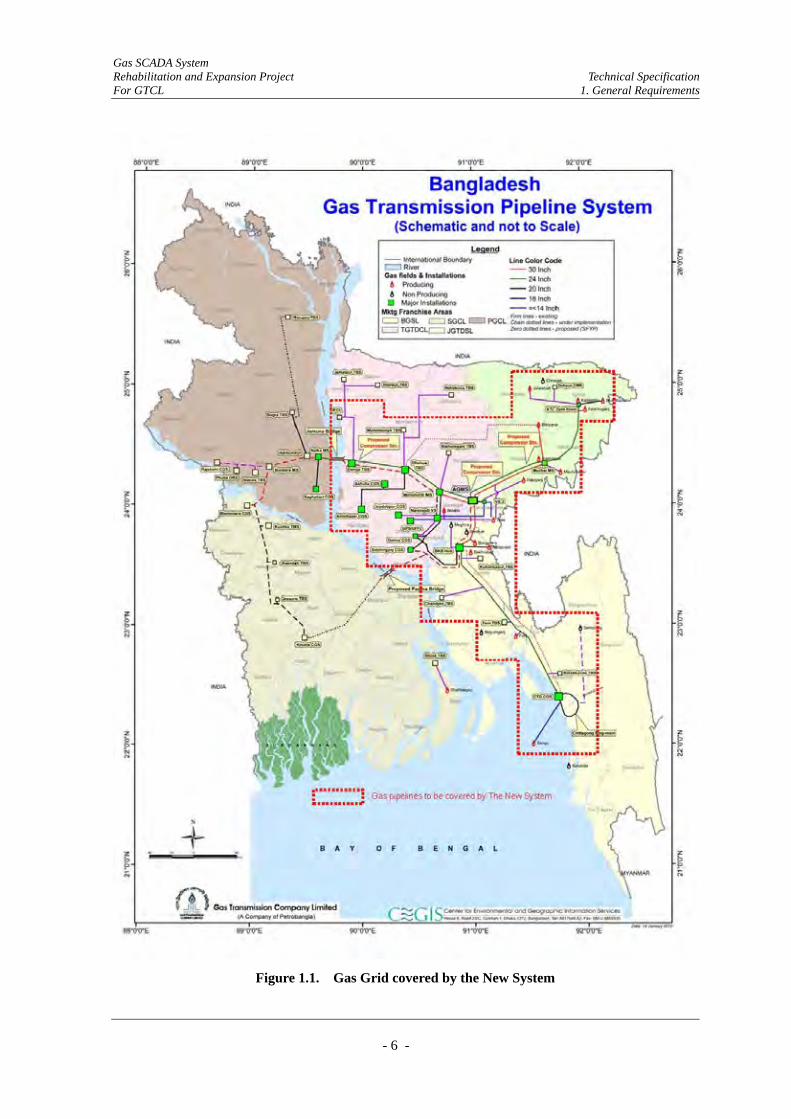
(1) Sections of the national gas grid that shall be covered by The New System are indicated in
Figure 1.1.
Gas SCADA System Rehabilitation and Expansion Project Technical Specification For GTCL 1. General Requirements
- 6 -
Figure 1.1. Gas Grid covered by the New System
Gas SCADA System Rehabilitation and Expansion Project Technical Specification For GTCL 1. General Requirements
- 7 -
1.3.6. Site Description
(1) Introduction
There are several classifications of sites which are defined below. The Site List
(Appendix-1) identifies the classification of each site to be included in The New System.
(2) Control Center (CC)
1) The Main Control Center (MCC) of the New System is located at Demra
approximately 20km east of Dhaka.
2) The Auxiliary Control Center (ACC) of the New System is located at Ashuganj
approximately 90km northeast of Dhaka.
3) Both Control Centers enable the Employer to supervise and control the entire gas
pipeline network covered by the New System.
(3) Master Telemetry Station (MTS)
1) There are 20 Master Telemetry Stations that communicate with their associated New
RTU(s) and Control Center as relay station. The existing radio equipment rooms and
towers shall be utilized for MTS.
(4) Gas Metering and Regulating Station
1) There are dozens of gas metering & regulating stations to be monitored by the New
System under different classifications as below.
GMS: Gas Manifold Station
CGS: City Gate Station
TBS: Town Bordering Station
RMS: Regulating & Metering Station
DRS: District Regulating Statio
CMS: Customer Metering Station
MS: Metering Station
2) The New System shall monitor the gas flow volume at these sites.
(5) Gas Field
1) There are 20 Gas Fields to be incorporated in the New System.
2) The New System shall monitor the inlet gas volume from these sites.

Gas SCADA System Rehabilitation and Expansion Project Technical Specification For GTCL 1. General Requirements
- 8 -
(6) Bulk Consumers
1) Power stations (PS) and fertilizer factories (FF), which are the largest consumers of
gas in the industrial sector, are defined as bulk consumers to be monitored by the New
System.
2) The New System shall monitor the outlet gas volume feeding the bulk consumers.
(7) Main Line Valve Stations (VS)
1) There are dozens of main line valve stations (VS) to be monitored by the New System.
2) The New System shall monitor the open/close status of these valves. Further control
these valves shall be provided.
(8) Petrobangla and Operating Companies’ Head Office
The head office of Petrobangla and other major operating companies shall be equipped with
an Operating Company Terminal (OCT) and extension telephone for the monitoring of the
entire gas grid covered by the New System and for internal/direct liaison.
1.3.7. Gas Pipeline Operation Philosophy
(1) The Employer will receive requests or nominations from distribution companies for the
supply of gas at designated sites on a periodical basis.
(2) The Employer will also establish the levels of gas to be provided to the National Gas Grid
by production companies on a regular basis.
(3) The Employer will plan for the transmission of gas through the National Gas Grid in
accordance with the demand as put forward by distribution companies under their contract
with the production companies.
(4) The Employer will provide figures for the quantity of gas flowing into and out of the
National Gas Grid to Petrobangla and the other Operating Companies to support billing and
payment for gas and other financial systems such as periodic accounts or planning.

Gas SCADA System Rehabilitation and Expansion Project Technical Specification For GTCL 1. General Requirements
- 9 -
1.4. Intended Purpose of the New System
(1) SCADA System
The intended purpose of the SCADA System is to ensure for GTCL that the natural gas
transmission pipeline is:
1) Capable of being operated and maintained safely, effectively and efficiently.
2) Equipped with operational interfaces that will enable the efficient monitoring and
control of the natural gas transmission pipeline from both of the Master Control Center
(MCC) and the Auxiliary Control Center (ACC).
The SCADA System shall permit data acquisition and control functions to be performed at
remote locations while providing the capability to monitor and control distributed functions
from MCC and ACC.
The Master Control Center (MCC) shall be the central operating center to monitor and
control the pipeline network.
The Auxiliary Control Center (ACC) shall be the hot-standby operating center with the
same functionality and operating capability as the MCC.
(2) Communication System
The intended purpose of the Communication System is to:
1) Provide adequate communication ability such as ensuring that the GTCL natural gas
transmission pipeline is capable of being operated and maintained safely, effectively
and efficiently.
2) Provide properly integrated communication interfaces among all sites and operating
companies.
3) Make the operating staff aware of any abnormal operating conditions in a timely and
effective manner to enable them to minimize consequential damage.
1.5. Brief Description of the New System
1.5.1. The SCADA System
The system shall be based around two Control Centers geographically separated for security
purposes, with identical facilities and a redundant server configuration for resilience and
Gas SCADA System Rehabilitation and Expansion Project Technical Specification For GTCL 1. General Requirements
- 10 -
additional security.
The Main Control Center (MCC) is located at Demra, 20 km south-east of Dhaka and the
Auxiliary Control Center (ACC) is at Ashuganj, 90 km north-east of Dhaka. The database will
be transferred via communication network between the servers at MCC and ACC.
The servers shall support HMI workstations in the control rooms and Operating Company
Terminals (OCTs) to be installed at the Gas Operating Company Head Offices throughout
Bangladesh to provide the facilities for Gas Plant monitoring, pipeline operation management,
maintenance dispatch, production planning and training.
An on-line modeling package shall be incorporated into the SCADA System to support gas leak
detection, load balancing and scheduling.
RTUs shall be installed at sites classified as below, throughout the existing gas pipeline network
covered by the Project, to retrieve data and transmit them to the MCC and the ACC.
(1) At Original Sites
All RTUs that are currently installed at original site shall be replaced with New RTU.
(2) At Additional Sites
Currently no RTUs are installed at the Additional Sites, thus New RTUs shall be installed.
(3) At Future Sites
GTCL and operating companies plan to construct some sites for gas transmission operation.
These planned sites may not be constructed by the completion of the Project therefore
RTUs shall be designed and supplied to the Employer.
Batteries shall be installed in the RTU cabinet to provide power back up and maintain equipment
operation for a full 24 hours on loss of the public electricity supply. Solar panels are equipped at
some existing sites without public electricity supply and these existing solar panels shall be
replaced. At additional sites without public electricity supply, solar panels shall be installed on
the RTU shelter roofs to provide the power necessary to energize the RTU equipment and
pipeline instrumentation.
Field Instruments shall be installed for all the Additional Sites and some of the Existing Sites
that have extended streams without flow measurement. The applicable sites, type and quantity of
the instruments are shown in the RTU list.
Gas SCADA System Rehabilitation and Expansion Project Technical Specification For GTCL 1. General Requirements
- 11 -
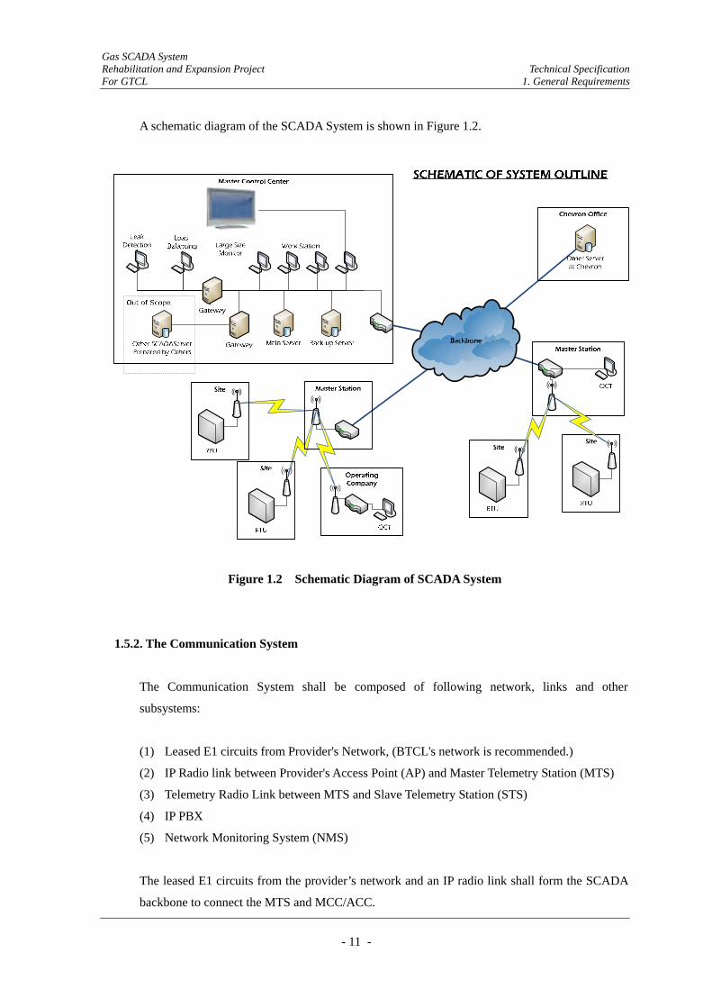
A schematic diagram of the SCADA System is shown in Figure 1.2.
Figure 1.2 Schematic Diagram of SCADA System
1.5.2. The Communication System
The Communication System shall be composed of following network, links and other
subsystems:
(1) Leased E1 circuits from Provider's Network, (BTCL's network is recommended.)
(2) IP Radio link between Provider's Access Point (AP) and Master Telemetry Station (MTS)
(3) Telemetry Radio Link between MTS and Slave Telemetry Station (STS)
(4) IP PBX
(5) Network Monitoring System (NMS)
The leased E1 circuits from the provider’s network and an IP radio link shall form the SCADA
backbone to connect the MTS and MCC/ACC.
Gas SCADA System Rehabilitation and Expansion Project Technical Specification For GTCL 1. General Requirements
- 12 -
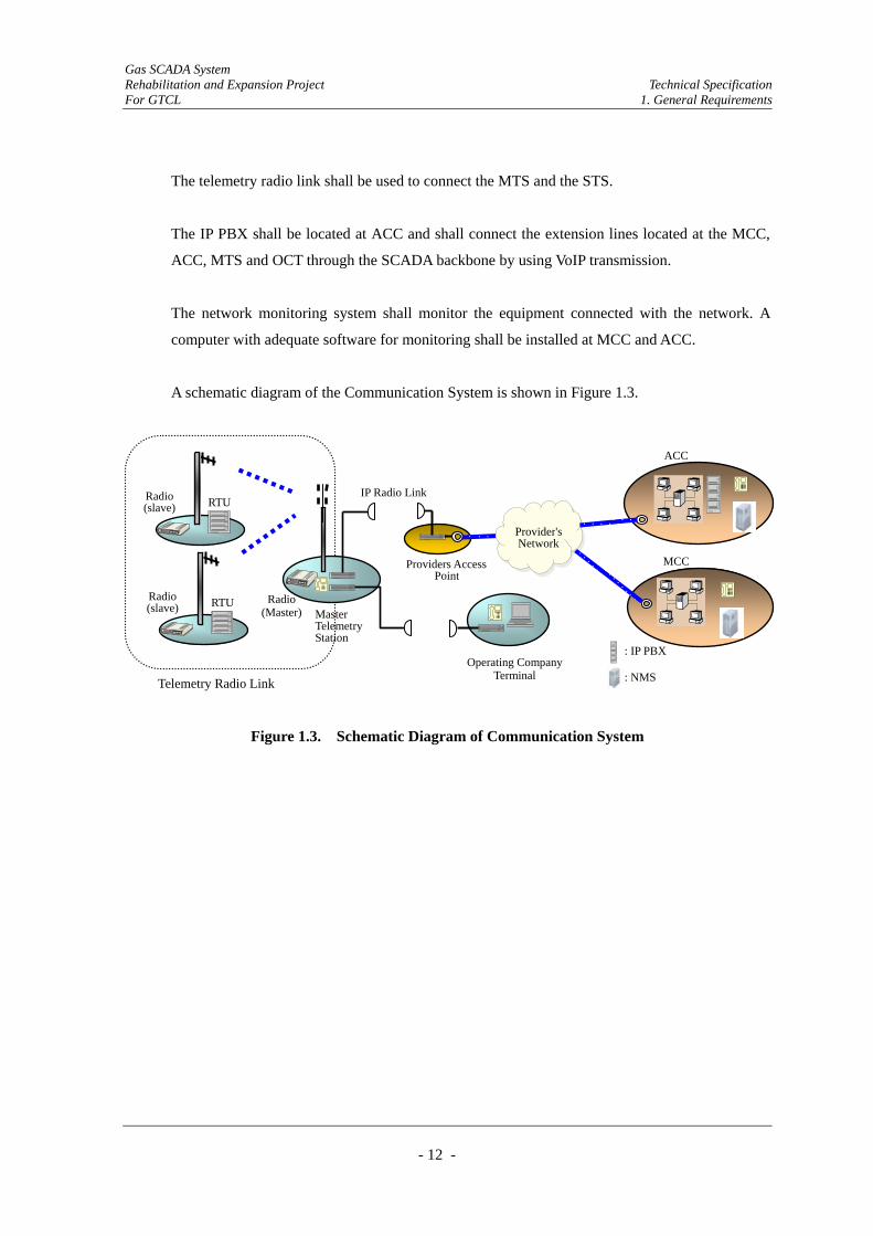
The telemetry radio link shall be used to connect the MTS and the STS.
The IP PBX shall be located at ACC and shall connect the extension lines located at the MCC,
ACC, MTS and OCT through the SCADA backbone by using VoIP transmission.
The network monitoring system shall monitor the equipment connected with the network. A
computer with adequate software for monitoring shall be installed at MCC and ACC.
A schematic diagram of the Communication System is shown in Figure 1.3.
Figure 1.3. Schematic Diagram of Communication System
Providers AccessPoint
IP Radio LinkRTU Radio
(slave)
Radio (Master)
RTU Radio (slave)
Telemetry Radio Link
Master TelemetryStation
Operating CompanyTerminal
ACC
MCC
Provider'sNetwork
: IP PBX : NMS

Gas SCADA System Rehabilitation and Expansion Project Technical Specification For GTCL 1. General Requirements
- 13 -
1.6. Applicable Standards
(1) A “standard” is a published specification that establishes a common language and contains a
technical specification or other precise criteria; it is designed to be used consistently, as a rule,
guideline or definition. For the purpose of the Contract the term “standard” encompasses the
expression “code of practice” and “regulation”.
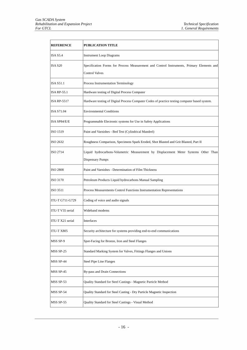
(2) The design, execution and completion of the Works shall be governed by, but not limited to,
the applicable standards and codes listed in the following table:
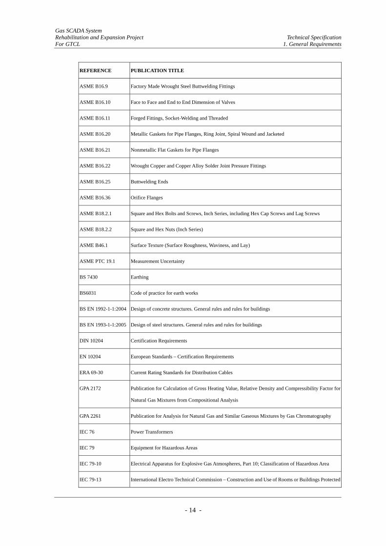
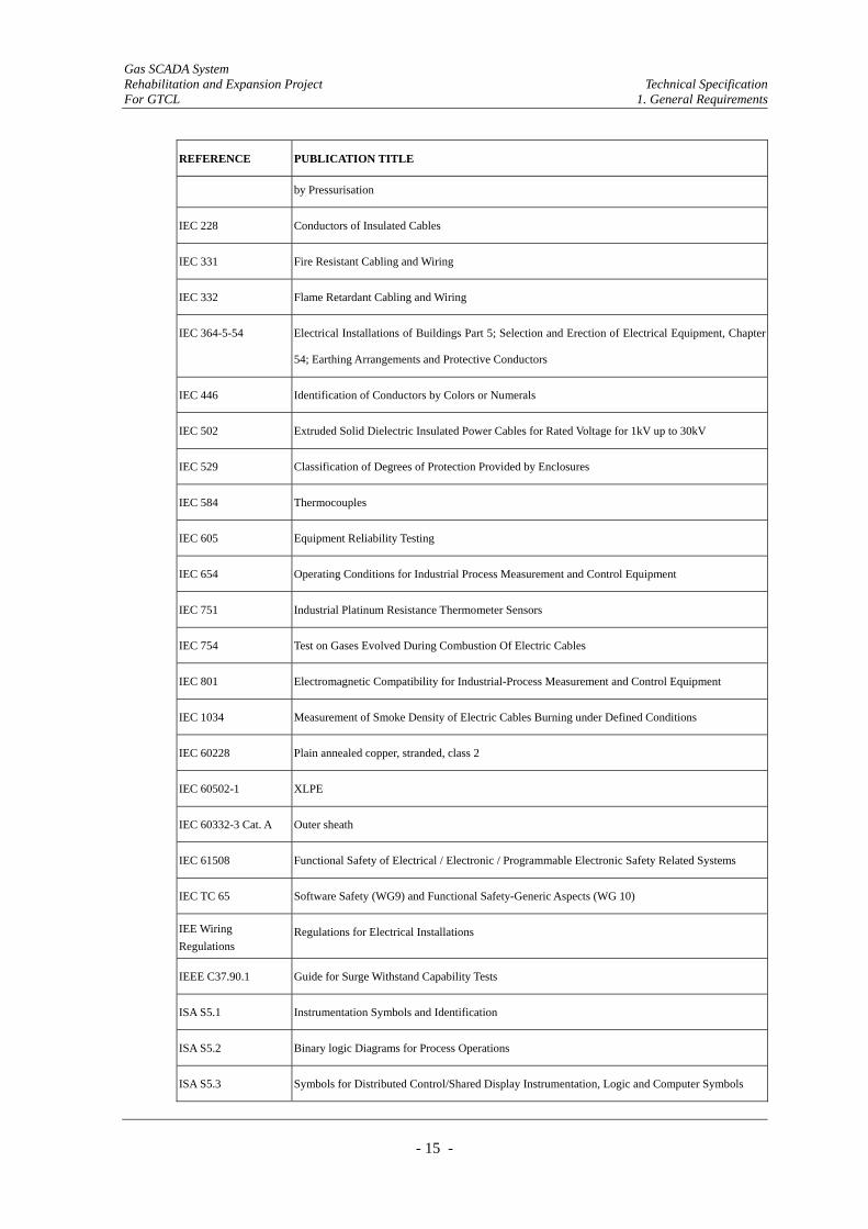
Table 1.1. List of Applicable Standards and Codes
REFERENCE PUBLICATION TITLE
AGA Report No. 3 Orifice Metering of Natural Gas (Part 2); specification and installation requirements
AGA Report No. 7 Measurement of Gas by Turbine Meters
AGA Report No. 8 AGA Compression factor of Natural gas and Hydrocarbon gas Report No. 8
AGA Report No. 9 Measurement of Gas by Multi-path Ultrasonic Meters
API 1104 Standard for Welding Pipelines and Related Facilities
API 2530 Manual of Petroleum Measurement Standards
API 2534 Measurement Control Charts and Statistical Methods for Petroleum Metering Systems
API RP 17A Pipe Flanges and Pipe Fittings
API RP 500 Classification of Locations for Electrical Installations
API RP 550 Manual on installation of Refinery, Instruments and Control Systems
API RP 551 Processing, Measurement, Instrumentation
API RP 554 Process Instrumentation and Control
API RP 2003 Protection against Ignitions arising out of Static Lighting and Stray Currents
API Spec 2B Fabrication of Structural Steel Pipe
API RP 750 Management of Process Hazards
ASME B1.20.1 Pipe Threads, General Purpose, Inch
ASME B16.5 Pipe Flanges and Flanged Fittings
Gas SCADA System Rehabilitation and Expansion Project Technical Specification For GTCL 1. General Requirements
- 14 -
REFERENCE PUBLICATION TITLE
ASME B16.9 Factory Made Wrought Steel Buttwelding Fittings
ASME B16.10 Face to Face and End to End Dimension of Valves
ASME B16.11 Forged Fittings, Socket-Welding and Threaded
ASME B16.20 Metallic Gaskets for Pipe Flanges, Ring Joint, Spiral Wound and Jacketed
ASME B16.21 Nonmetallic Flat Gaskets for Pipe Flanges
ASME B16.22 Wrought Copper and Copper Alloy Solder Joint Pressure Fittings
ASME B16.25 Buttwelding Ends
ASME B16.36 Orifice Flanges
ASME B18.2.1 Square and Hex Bolts and Screws, Inch Series, including Hex Cap Screws and Lag Screws
ASME B18.2.2 Square and Hex Nuts (Inch Series)
ASME B46.1 Surface Texture (Surface Roughness, Waviness, and Lay)
ASME PTC 19.1 Measurement Uncertainty
BS 7430 Earthing
BS6031 Code of practice for earth works
BS EN 1992-1-1:2004 Design of concrete structures. General rules and rules for buildings
BS EN 1993-1-1:2005 Design of steel structures. General rules and rules for buildings
DIN 10204 Certification Requirements
EN 10204 European Standards – Certification Requirements
ERA 69-30 Current Rating Standards for Distribution Cables
GPA 2172 Publication for Calculation of Gross Heating Value, Relative Density and Compressibility Factor for
Natural Gas Mixtures from Compositional Analysis
GPA 2261 Publication for Analysis for Natural Gas and Similar Gaseous Mixtures by Gas Chromatography
IEC 76 Power Transformers
IEC 79 Equipment for Hazardous Areas
IEC 79-10 Electrical Apparatus for Explosive Gas Atmospheres, Part 10; Classification of Hazardous Area
IEC 79-13 International Electro Technical Commission – Construction and Use of Rooms or Buildings Protected
Gas SCADA System Rehabilitation and Expansion Project Technical Specification For GTCL 1. General Requirements
- 15 -
REFERENCE PUBLICATION TITLE
by Pressurisation
IEC 228 Conductors of Insulated Cables
IEC 331 Fire Resistant Cabling and Wiring
IEC 332 Flame Retardant Cabling and Wiring
IEC 364-5-54 Electrical Installations of Buildings Part 5; Selection and Erection of Electrical Equipment, Chapter
54; Earthing Arrangements and Protective Conductors
IEC 446 Identification of Conductors by Colors or Numerals
IEC 502 Extruded Solid Dielectric Insulated Power Cables for Rated Voltage for 1kV up to 30kV
IEC 529 Classification of Degrees of Protection Provided by Enclosures
IEC 584 Thermocouples
IEC 605 Equipment Reliability Testing
IEC 654 Operating Conditions for Industrial Process Measurement and Control Equipment
IEC 751 Industrial Platinum Resistance Thermometer Sensors
IEC 754 Test on Gases Evolved During Combustion Of Electric Cables
IEC 801 Electromagnetic Compatibility for Industrial-Process Measurement and Control Equipment
IEC 1034 Measurement of Smoke Density of Electric Cables Burning under Defined Conditions
IEC 60228 Plain annealed copper, stranded, class 2
IEC 60502-1 XLPE
IEC 60332-3 Cat. A Outer sheath
IEC 61508 Functional Safety of Electrical / Electronic / Programmable Electronic Safety Related Systems
IEC TC 65 Software Safety (WG9) and Functional Safety-Generic Aspects (WG 10)
IEE Wiring Regulations
Regulations for Electrical Installations
IEEE C37.90.1 Guide for Surge Withstand Capability Tests
ISA S5.1 Instrumentation Symbols and Identification
ISA S5.2 Binary logic Diagrams for Process Operations
ISA S5.3 Symbols for Distributed Control/Shared Display Instrumentation, Logic and Computer Symbols
Gas SCADA System Rehabilitation and Expansion Project Technical Specification For GTCL 1. General Requirements
- 16 -
REFERENCE PUBLICATION TITLE
ISA S5.4 Instrument Loop Diagrams
ISA S20 Specification Forms for Process Measurement and Control Instruments, Primary Elements and
Control Valves
ISA S51.1 Process Instrumentation Terminology
ISA RP-55.1 Hardware testing of Digital Process Computer
ISA RP-5517 Hardware testing of Digital Process Computer Codes of practice testing computer based system.
ISA S71.04 Environmental Conditions
ISA SP84/E/E Programmable Electronic systems for Use in Safety Applications
ISO 1519 Paint and Varnishes - Bed Test (Cylindrical Mandrel)
ISO 2632 Roughness Comparison, Specimens Spark Eroded, Shot Blasted and Grit Blasted, Part II
ISO 2714 Liquid hydrocarbons-Volumetric Measurement by Displacement Meter Systems Other Than
Dispensary Pumps
ISO 2808 Paint and Varnishes - Determination of Film Thickness
ISO 3170 Petroleum Products Liquid hydrocarbons Manual Sampling
ISO 3511 Process Measurements Control Functions Instrumentation Representations
ITU-T G711-G729 Coding of voice and audio signals
ITU-T V35 serial Wideband modems
ITU-T X21 serial Interfaces
ITU-T X805 Security architecture for systems providing end-to-end communications
MSS SP-9 Spot-Facing for Bronze, Iron and Steel Flanges
MSS SP-25 Standard Marking System for Valves, Fittings Flanges and Unions
MSS SP-44 Steel Pipe Line Flanges
MSS SP-45 By-pass and Drain Connections
MSS SP-53 Quality Standard for Steel Castings - Magnetic Particle Method
MSS SP-54 Quality Standard for Steel Casting - Dry Particle Magnetic Inspection
MSS SP-55 Quality Standard for Steel Castings - Visual Method

Gas SCADA System Rehabilitation and Expansion Project Technical Specification For GTCL 1. General Requirements
- 17 -
REFERENCE PUBLICATION TITLE
MSS SP-61 Hydrostatic Testing of Steel Valves
MSS SP-80 Bronze Gate, Globe and Check Valves
MSS SP-82 Valve Pressure Testing Methods
MSS SP-92 Valve User Guide
NFPA 101 Code for Safety to Life from Fire in Building and Structures
NFPA 110 Emergency and Standby Power Systems
NFPA 321 Standard on Basic Classification of Flammable and Combustible Liquids
NFPA 496 Standard for Purged and Pressurised Enclosures for Electrical Equipment
OSHA Construction Standard for Excavations
RS-222-C Structural Standards for Steel Antenna Towers and Antenna Supporting Structures
SAMA PMC 33.1C Radio Frequencies Sensitivity Test
UTM Universal Transverse Mercator
(3) The Contractor shall demonstrate compliance with all of the above standards and codes at all
stages of implementation of the Works. In the event of conflict between the various listed
standards, the stricter provisions shall prevail.
(4) The Contractor shall comply with all Bangladeshi Safety Legislation and Regulations insofar
as they are applicable to the carrying out of the Works.
(5) The Contractor shall be responsible for sourcing and obtaining copies of the latest edition of
all standards and codes, of which two copies of each shall be provided to the Engineer.
(6) The latest versions of the above standards and codes shall be applicable for implementation
purposes unless otherwise specifically stated elsewhere in this document.
(7) If circumstances are encountered in which the requirements of a standard or code cannot be
met, then a variation request shall be prepared by the Contractor and submitted to the
Employer. The Contractor shall provide full technical justifications for such variation request.
Gas SCADA System Rehabilitation and Expansion Project Technical Specification For GTCL 1. General Requirements
- 18 -
(8) Where specific standards, codes of practice or industry norms are stated in this document, the
Contractor may nonetheless use any other standard that will result in the quality of the Works
being equivalent to or higher than the quality that would have resulted through the
application of the stated standard.
(9) All of the relevant standards are to be adhered to and used in the integrated and
interdependent manner in which the issuing body intended.
(10) In certain areas of science and engineering there are no published standards. In such cases the
Contractor is obliged to ensure that in the design, execution and completion of the Works the
Contractor has at all times complied with established “best practice”. To demonstrate
compliance the Contractor may draw upon the latest technical references in such areas and
refer thereto in the preparation of the Design.
(11) The Contractor’s technical documents for their design, installation, commissioning and
testing shall identify the standards which are applied to.
Gas SCADA System Rehabilitation and Expansion Project Technical Specification For GTCL 2. Scope of Work
- 19 -
2. Scope of Work
2.1. Introduction
(1) The Project shall be implemented by EPC (Engineering, Procurement and Construction)
Contract. The Contract Scope of Works shall include, but are not limited to, engineering,
detailed design, manufacture, installation, construction, testing, commissioning, training
and post-implementation services.
(2) The Scope of Work to be carried out by the Contractor at each site is specified in the Site
Information & Scope of Work (Appendix-2).
(3) The Site Information & Scope of Work is based on a conceptual design and provides basic
information of each site and an overview of each site’s scope of work. The Contract is the
EPC Contract therefore, the Site Information & Scope of Work does not relieve the
Contractor of any responsibility for any aspects of the design and implementation, nor for
allowing for any variation between the Site Information & Scope of Work and the specific
aspects of implementing the Contract Works.
2.2. Project Management
(1) The Contractor shall be responsible for the Project Management, and nominate a single
Project Manager to be mainly based in Bangladesh. The Project Manager shall be the point
of contact during the Contract and shall be responsible for all aspects of the Contractor’s
work including, but not limited to, program management, progress reporting, finance,
safety and technical compliance.
(2) The Contractor shall produce a Project Plan as specified in Section 3.2.1. This shall address
both Bangladesh and overseas based activities.
(3) The Contractor shall monitor performance against the Project Plan and produce monthly
reports detailing progress, activities undertaken, problems and future activities.

Gas SCADA System Rehabilitation and Expansion Project Technical Specification For GTCL 2. Scope of Work
- 20 -
2.3. Site Investigation
(1) The Contractor shall be responsible for defining and implementing all necessary Site
investigations, including a sampling and testing program.
(2) The purpose of the Site investigations shall be to identify and quantify those characteristics
or properties of the materials found on or under the Site for use in the design and execution of
the Works. The definition of what investigation is required shall take into account the data
provided at the bid stage and any assumptions or conclusions drawn from such data with
respect to the characteristics or properties of materials.
2.4. Engineering and Detailed Design
The Contractor shall be responsible for the engineering and detailed design of the New System
in accordance with the requirements specified in this document.
2.5. Manufacture
The Contractor shall manufacture the equipment required for the New System in accordance
with the design.
2.6. Factory Acceptance Test (FAT)
(1) The requirements for FAT are specified in greater detail in Section 11.3.1.
(2) The Contractor shall perform the Factory Acceptance Test (FAT) of the equipment
manufactured for the New System before any item of the equipment is packed or delivered
from the manufacturer's factory.
(3) The FAT shall be witnessed by the Employer and/or the Engineer.
Gas SCADA System Rehabilitation and Expansion Project Technical Specification For GTCL 2. Scope of Work
- 21 -
2.7. Pre-Installation Site Works
The Contractor shall be responsible for pre-installation site works including, but not limited to,
the following works:
(1) The Contractor shall refurbish existing rooms, foundations and sunshades where equipment
is installed prior to the installation works as specified in Section 10.
(2) The Contractor shall construct the foundations and sunshades for new equipment prior to
the installation works as specified in Section 10.
(3) The Contractor shall carry out all necessary cabling works prior to the installation works as
specified in Section 9.
2.8. Installation
(1) The requirements for delivery and installation are specified in greater detail in Section 5.
(2) The Contractor shall be responsible for delivery of all equipment, materials and tools to
Bangladesh and onward to the sites.
(3) The Contractor shall be responsible for providing adequate and appropriate storage
facilities for all equipment, materials and tools.
(4) The Contractor shall install equipment in accordance with the design, specification, safety
plans and method statements.
2.9. Site Acceptance Test (SAT)
(1) The requirements for SAT are specified in greater detail in Section 11.3.2.
(2) The Contractor shall perform the Site Acceptance Test (SAT) of the equipment and software
for the New System after they are fully assembled/installed at sites.
(3) The SAT shall be witnessed by the Employer and the Engineer.
Gas SCADA System Rehabilitation and Expansion Project Technical Specification For GTCL 2. Scope of Work
- 22 -
2.10. Commissioning
The Contractor shall carry out commissioning tests to demonstrate the satisfactory operation of
the New System prior to Taking-Over as specified in Section 11.3.3.
2.11. System Taking-Over
Following satisfactory completion of the Final System Tests as specified in Section 11.3.4. and
provided the other requirements have been met, the System Taking-Over shall take place when
the Employer commences full operation of the New System.
2.12. Operation and Maintenance Support
(1) The requirements for the operation and maintenance support are specified in greater detail
in Section 12.
(2) The Contractor shall support two years warranty period along with Operation and
Maintenance (O&M) support.
2.13. Training
(1) The requirements for training are specified in greater detail in Section 13.
(2) Training shall be provided to the Employer’s staff during installation, commissioning,
operation and maintenance of the New System. This activity shall be scheduled to allow
these staff to contribute to the site testing and setting work.
2.14. Temporary Site Facilities
2.14.1. General
(1) The Contractor shall be fully responsible for all necessary temporary facilities for the
Gas SCADA System Rehabilitation and Expansion Project Technical Specification For GTCL 2. Scope of Work
- 23 -
implementation of the Project.
(2) The Contractor shall provide temporary local site facilities for the Employer and the
Engineer where travel back to Dhaka, Demra or Ashuganj is not feasible in a day.
(3) The Contractor shall provide temporary office and accommodation facilities for the
Employer and the Engineer at Demra and Ashuganj with the facilities as outlined below.
(4) The Contractor shall be fully responsible for locating and arranging the use of sites for the
temporary facilities, temporary accommodation and such utilities as required by the
Contractor, the Employer and the Engineer.
(5) Alcohol, liquor, firearms and drugs shall be strictly forbidden in the camp area and
construction site.
2.14.2. Local Site Facilities
In addition to that required by himself, the Contractor shall provide, in areas where travel back
to Dhaka, Demra or Ashuganj is not feasible in a day, local site facilities for the Employer and
the Engineer including:
(1) Indoor working space at site (or reasonably close to the site) with adequate office furniture
for the Employer and the Engineer (minimum 4 staff).
(2) Full board accommodations for the Employer with following facilities:
One air conditioned bedroom for each staff
Western style attached and/or common bathroom with hot water
Communication facilities such as internet connection and/or facsimile
2.14.3. Office Facilities
2.14.3.1. General
(1) In addition to that required by himself, the Contractor shall further provide the following
facilities at each of Demra and Ashuganj;

Gas SCADA System Rehabilitation and Expansion Project Technical Specification For GTCL 2. Scope of Work
- 24 -
1) Project Office
2) Computer equipment
for the exclusive use of the staff of the Employer and the Engineer during the construction
period and with a demobilization period of up to three (3) months after issue of the
Taking-Over Certificate.
(2) All items in Sections 2.14.3.3. shall become the property of the Employer at the time of
issuance of the Taking-Over Certificate.
2.14.3.2. Project Office
(1) The Contractor shall provide office space adequate for minimum 10 staff with following
facilities, and be responsible for the security, cleaning and regular maintenance.
1) Air conditioned office rooms.
2) 1 No. air conditioned meeting room.
3) Broadband internet connection and LAN system with regular maintenance.
4) Office furniture adequate for the entire office space mentioned above.
5) Kitchen with cold & hot water supply, refrigerator, table wares and other necessary
facilities for tea/coffee and light meal services.
6) Toilets adequate for minimum 10 staff’s use.
7) Fire extinguishers in accordance with local regulation.
8) Office boys to provide general office service.
9) Provision of all consumable items for daily office use throughout the Project.
10) Adjacent parking space for minimum 5 vehicles.
2.14.3.3. Computer Equipment
As a minimum the following computer equipment shall be provided by the Contractor and be
dispersed as directed by the Engineer:
(1) 1 No. reputable brand name latest desktop PC with UPS.
(2) 2 No. reputable brand name laptop PC.
(3) 1 No. A3/A4 size color laser printer/scanner/photocopier with regular maintenance service.
(4) Latest version of following software shall be pre-loaded on all PCs mentioned above and
also provided on CD/DVD-ROM:
1) Microsoft Windows
2) Microsoft Internet Explorer

Gas SCADA System Rehabilitation and Expansion Project Technical Specification For GTCL 2. Scope of Work
- 25 -
3) Microsoft Outlook
4) Microsoft Office
5) Word module for word processing in Bangla script
6) Microsoft Project
7) Anti-virus software
8) AutoCAD
2.14.4. Living and Messing Accommodation (Demra and Ashuganj)
(1) The Contractor shall provide two fully furnished houses (or flats) with following facilities
for the accommodations of the Employer during installation and commissioning period and
with a demobilization period of up to three (3) months after issue of the Taking-Over
Certificate at each of Demra and Ashuganj, and be responsible for the security, cleaning and
regular maintenance.
1) One air conditioned master bedroom with attached bathroom.
2) Two air conditioned bedrooms
3) One common bathroom
4) Hot water supply at all bathrooms and kitchen.
5) Kitchen, Dinning and Lounge space
6) Satellite TV
7) Fire extinguishers in accordance with local regulation.
8) Three meals per day for all staff
9) Cooks and bearers necessary for daily meal, cleaning and maintenance.
10) Provision of all consumable items for general daily use.
11) Adjacent parking space for minimum 2 vehicles.
2.14.5. Supply of Electricity and Water
(1) The Contractor shall be solely responsible for all arrangements for, and charges associated
with, the provision and use of drinking quality water and electrical power (230V 50Hz) to
the offices, living and messing accommodation for the duration of the Construction Period.
(2) Drinking water quality shall be subject to independent laboratory tests at the expense of the
Contractor.
Gas SCADA System Rehabilitation and Expansion Project Technical Specification For GTCL 2. Scope of Work
- 26 -
(3) Attention is drawn to the non-reliability of electricity supplies from the National Power
Grid in Bangladesh. Supplies of power are often discontinuous for several hours during
each day. The Contractor shall provide and maintain an independent full capacity diesel
fuelled generator system, with standby, for supply of electricity to the offices, living and
messing accommodation.
2.14.6. Inspection Equipment
The Contractor shall supply for the exclusive use of the Engineer and his staff the equipment
required for inspection of the works. This equipment will be retained by the Employer at the
time of issuance of the Taking-Over Certificate.
2.14.7. Vehicles
(1) Within forty-five (45) days of Commencement of Works, the Contractor shall supply, for
the exclusive use of the Employer and the Engineer or their staff, the following vehicles or
similar approved and drivers. These vehicles will, become the property of the Employer at
the time of issuance of the Taking-Over Certificate.
1) Saloon cars, petrol and/or CNG fuelled, air conditioned, fully equipped, to carry four
(4) passengers and driver in comfort - 1 No. with driver.
2) Toyota Land Cruiser (long wheel base) or equivalent, petrol and/or CNG fuelled, air
conditioned, fully equipped - 4 No. with drivers.
(2) Four wheel drive vehicles shall have an engine capacity of not less than 4000 cc. The
saloon cars shall have an engine capacity of not less than 2000 cc.
(3) All vehicles supplied by the Contractor shall be new and in a fully road worthy condition.
The Contractor shall pay all costs including CD-VAT and other payments necessary to
allow them to be used freely on all public highways in Bangladesh and shall continue to
make such payments throughout the duration of the Contract until the issuance of the
Taking-Over Certificate.
(4) The Contractor shall insure all the above vehicles fully comprehensively for any driver and
all passengers up to 90 days after the issuance of the Taking-Over Certificate. The
insurance company shall be registered in Bangladesh and the policies approved by the
Gas SCADA System Rehabilitation and Expansion Project Technical Specification For GTCL 2. Scope of Work
- 27 -
Employer prior to delivery. Receipts of premium payments shall be submitted to the
Employer and copied to the Engineer at the time of delivery of the vehicles. Full policy
documents shall J be submitted to the Employer and copied to the Engineer within 30 days
of delivery.
(5) The Contractor shall provide fuel, oil and other consumables for these vehicles throughout
the Contract until the issuance of the Taking-Over Certificate.
(6) The Contractor shall maintain all vehicles supplied by him in fully road worthy condition,
including routine maintenance and all repairs and replacements as they become necessary.
Should any vehicle be off the road for maintenance purpose for more than 24 hours, the
Contractor shall supply an equivalent vehicle at no extra cost for the duration of the period
of service. All the conditions in this Clause shall apply to the replacement vehicle.
(7) If any vehicle is lost, damaged or stolen whilst in the possession of the Employer or the
Engineer, the Contractor shall immediately provide an equivalent replacement vehicle, at
his own expense. The Contractor shall assume responsibility for any legal and insurance
procedures resulting from any of the above eventualities.
2.14.8. Vehicle Equipment
(1) The four wheel drive vehicles shall be equipped with the following:
1) Water carrier of approximately 20 litre capacity
2) Fuel carrier of approximately 20 litre capacity
3) Shovel
4) Hi-lift jack
5) One spare wheel, with tyre
6) Sump guard, track guard and front fender grill bars
7) Seat covers, floor mats and cleaning materials
8) First aid kit, including blanket
9) Normal emergency tool kit
(2) In addition, the Contractor shall provide with each vehicle 4 No. new spare tyres at the time
of handing over of the vehicles to the Employer.
(3) The saloon car shall be equipped as appropriate as per the four (4) wheel drive vehicles.
Gas SCADA System Rehabilitation and Expansion Project Technical Specification For GTCL 2. Scope of Work
- 28 -
2.14.9. Assistance
(1) The Contractor shall render all necessary assistance to the Engineer and his staff in their
inspection, evaluation and supervision of the Works.
(2) The Contractor shall also provide such other labour as is required to attend nightly to the
office security and cleaning and other requirements and where required to assist the
Engineer and his staff in measuring, supervising, testing, checking and examining the
Contractor's work whether by day or night.
2.14.10. CD-VAT Charges on Imported Items
(1) The Employer shall be responsible for the payment of CD-VAT charges on items of
imported Materials and Plant incorporated in the Permanent Works.
(2) The Contractor shall be responsible for the payment of CD-VAT and other duties and
charges of all imported items and consumables provided as required in this section 2.14.
2.15. The Employer’s Scope of Work
For smooth implementation of the Project, GTCL shall be responsible to undertake the following
items.
(1) Undertakings by GTCL
1) Procedures for lands
In this Project, procured equipment and materials will be installed at the Sites owned by
GTCL or other companies who belong to the gas sector and have gas business with
GTCL. Therefore, necessary land-use permissions shall been obtained by GTCL so that
the Contractor can start their work without any delay.
2) Communication system lease contract between GTCL and BTCL
GTCL has decided to select the communication system provided by BTCL as the
communication backbone for the GTCL SCADA System. Accordingly, the lease
contract between GTCL and BTCL shall be made within one (1) month of Notice to
Proceed to the EPC Contractor.

Gas SCADA System Rehabilitation and Expansion Project Technical Specification For GTCL 2. Scope of Work
- 29 -
(2) Works by GTCL
1) Thermo-wells additionally required for the New System shall be installed by GTCL
prior to the issuance of “Notice To Proceed”.
2) The soundness of all transmitters, limit switches and/or supply power including related
cables and junction boxes at existing RTU sites and other related sites shall be checked
and repaired/replaced by GTCL as necessary prior to the issuance of “Notice To
Proceed”.
3) For the detection of a gas leakage from the pipelines covered by the Project, the precise
measurement of gas flow at whole intake and offtake points shall be indispensable.
Therefore, the current situation of the relevant points with respect to the gas flow
measuring capability shall be checked by GTCL and necessary countermeasures shall
be taken prior to the commencement of the Project.
4) The following information shall be provided by GTCL as a part of the tender document
for the EPC Contract:
a) Detailed information, such as the type and exact location of whole intake and
offtake points, valve stations, metering stations, etc., on GTCL and other related gas
pipeline networks
b) Layout and P&ID drawings of sites to be covered by the New System.

Gas SCADA System Rehabilitation and Expansion Project Technical Specification For GTCL 3. Contractor’s Key Management Responsibilities
- 30 -
3. Contractor’s Key Management Responsibilities
This chapter identifies the requirements of the Employer with respect to how the design, execution
and completion of the Works is to be planned, managed and administered by the Contractor. For the
most part it sets out detailed requirements that are to be read in conjunction with the more general
requirements stipulated in the Conditions of Contract, particularly (but not limited to) the
requirements of the following subsections:
1) 4.6 [Co-operation]
2) 5.2 [Contractor’s Documents]
3) 5.6 [As- Built Documents]
4) 5.7 [Operation and Maintenance Manuals]
This chapter also addresses general administrative matters and the coordination thereof between the
Employer’s Personnel and the Contractor.
3.1. Administrative Matters
3.1.1. Contractor’s Documents
(1) Certain Contractor’s Documents are specified in the Contract as being required by the
Engineer for review. The submission of such documents and the subsequent review thereof
shall be carried out under the provisions of Conditions of Contract subsection 5.2
[Contractor’s Documents].
(2) In respect of any of those Contractor’s Documents where the Contract is silent on the need
for submission, the Contractor is not required to submit such documents unless the Engineer
specifically requests the Contractor to do so. This is intended to ensure that the Engineer is
not inundated with data that is not critical to the review process, and the Contractor is
expected to cooperate with the Engineer to ensure that this intention is realised in practice.
The Contractor shall nonetheless provide or provide access to such other documents when so
requested, including the following:
1) Administration Documents: these are documents for discussion between the Contractor
and the Engineer in order to facilitate the establishment of various management and
communication systems, for example, those with respect to Quality Management
Systems. Such documents are indicated in the Employer’s Requirements, and the level
of detail required will be agreed between the Engineer and the Contractor.
2) General Records: documents such as those produced by the Contractor to record and
document his work and which are to be handed over to the Employer on completion of
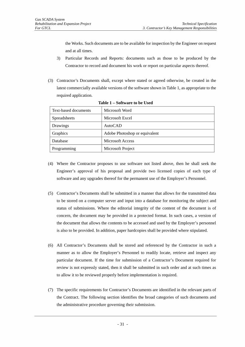
Gas SCADA System Rehabilitation and Expansion Project Technical Specification For GTCL 3. Contractor’s Key Management Responsibilities
- 31 -
the Works. Such documents are to be available for inspection by the Engineer on request
and at all times.
3) Particular Records and Reports: documents such as those to be produced by the
Contractor to record and document his work or report on particular aspects thereof.
(3) Contractor’s Documents shall, except where stated or agreed otherwise, be created in the
latest commercially available versions of the software shown in Table 1, as appropriate to the
required application.
Table 1 – Software to be Used
Text-based documents Microsoft Word
Spreadsheets Microsoft Excel
Drawings AutoCAD
Graphics Adobe Photoshop or equivalent
Database Microsoft Access
Programming Microsoft Project
(4) Where the Contractor proposes to use software not listed above, then he shall seek the
Engineer’s approval of his proposal and provide two licensed copies of each type of
software and any upgrades thereof for the permanent use of the Employer’s Personnel.
(5) Contractor’s Documents shall be submitted in a manner that allows for the transmitted data
to be stored on a computer server and input into a database for monitoring the subject and
status of submissions. Where the editorial integrity of the content of the document is of
concern, the document may be provided in a protected format. In such cases, a version of
the document that allows the contents to be accessed and used by the Employer’s personnel
is also to be provided. In addition, paper hardcopies shall be provided where stipulated.
(6) All Contractor’s Documents shall be stored and referenced by the Contractor in such a
manner as to allow the Employer’s Personnel to readily locate, retrieve and inspect any
particular document. If the time for submission of a Contractor’s Document required for
review is not expressly stated, then it shall be submitted in such order and at such times as
to allow it to be reviewed properly before implementation is required.
(7) The specific requirements for Contractor’s Documents are identified in the relevant parts of
the Contract. The following section identifies the broad categories of such documents and
the administrative procedure governing their submission.
Gas SCADA System Rehabilitation and Expansion Project Technical Specification For GTCL 3. Contractor’s Key Management Responsibilities
- 32 -
3.1.2. Design Submissions
(1) The purpose of the Design Submissions is to allow the Employer’s personnel to:
1) Monitor the progress of design
2) Satisfy themselves that the design is being performed and verified in a competent,
professional manner
3) Satisfy themselves that the design can be effectively and safely built
4) Satisfy themselves that the Contractor is complying with any other obligation under
the Contract.
(2) The Contractor is required to submit the design work required for review, including
specifications, in the following order of stages:
1) Stage 1 - Preliminary Design
2) Stage 2 - Detailed Design
(3) The Contractor is not authorised to proceed to the next stage of design until he has received
from the Engineer a notice of “no objection” for the stage of design under review.
(4) The Design Submissions shall be structured, referenced and presented in a manner that:
1) Facilitates the achievement of their intended purpose
2) Allows them to be filed to form part of what will eventually be a comprehensive,
integrated and complete record of the design.
(5) A time schedule covering the submission of the Contractor’s Documents related to design
(the Design Submission Schedule or DSS) shall be incorporated as part of the Programme
referred to in the Conditions of Contract subsection 8.3 [Programme]. The DSS shall
identify the attributes of each Design Submission. The minimum attributes shall be:
1) The Design Stage covered by the submission (either the Conceptual Design, the
Preliminary Design or the Detailed Design)
2) Whether the design work covers Permanent Works or Temporary Works
3) Where Facility references are applicable, the appropriate code for that part of the
Works forming the subject of the submission
4) The date by which the submission is due
5) The date for completion of the review.
(6) Except as may otherwise be agreed with the Engineer, the Design Submission for each
respective Facility shall be comprehensive and cover the entirety of the design for that
Gas SCADA System Rehabilitation and Expansion Project Technical Specification For GTCL 3. Contractor’s Key Management Responsibilities
- 33 -
Facility. Partial Design Submissions for a Facility will not be acceptable to the Engineer.
The review period for any Facility shall be deemed not to have commenced until such time
as the Contractor has submitted the full design according to the requirements as stipulated
herein.
(7) Should the Engineer not require a particular aspect of the design to be submitted for review,
then this will be identified by the Engineer on a copy of the DSS returned to the Contractor.
3.1.3. As-Built Documents
(1) The As-Built Documents shall be comprised of:
1) Drawings of the Permanent Works as installed (including a ‘family tree’ index
incorporating all drawings from suppliers and subcontractors), indicating all changes
made to the original Drawings issued for construction/installation purposes
2) Specifications of the Permanent Works as installed, indicating all changes made to the
original Specifications issued for construction/installation purposes
3) A copy of all Variations and Change orders issued by the Engineer during the execution
of the Works
4) A full report on all non-conformities identified and corrective measures taken
5) A copy of all construction records, including all test results
6) A copy of all Standards and Codes of Practice applicable to the Works, and
7) Operation and maintenance documentation, including all; applicable product
information, required to operate and maintain the system.
(2) Drafts of the As-Built Documents shall be submitted in paper hard-copy format (5 copies)
with the exception of the item (6) stated above. The finally agreed set of As-Built Documents
shall be submitted in 1 original and 5 paper copies, together with 2 editable soft copies. For
the Standards and Codes as described in item (6) above, 1 original paper hard format or 1
CD-ROM format shall be submitted.
(3) A copy of all indicated software provided for operating and maintaining the completed
Works (i.e. software especially written or standard software customized by specialists),
together with all supporting documentation relating thereto (including “Help” files and the
like), shall be provided by the Contractor to complete the As-Built Documents submission
data.

Gas SCADA System Rehabilitation and Expansion Project Technical Specification For GTCL 3. Contractor’s Key Management Responsibilities
- 34 -
(4) The original design shall be clearly distinguishable from what has been built. On drawings,
this may be achieved by layer separation, line colour or line type, or a combination thereof.
In the Specifications, this shall be achieved by any changes being identified in red. Where
words have been deleted from the Specifications, the deleted words shall remain in view but
be struck through with a line.
(5) Each change from the original design shall be referenced to the authorization giving rise to
that change.
(6) The documentation of Variations to the Works arising from Conditions of Contract
subsection 13.2 [Variations and Adjustments] shall be in paper hard-copy format. Each
variation shall be assigned a unique reference code and shall be contained in a separate file
identified with the Variation reference number. The file shall contain all communications
and documents related to that variation, filed in chronological order. A table of contents shall
be provided at the front of each file.
3.1.4. Operation and Maintenance Manuals
(1) The Contractor is required to prepare an operating and maintenance manual for the System.
Specifically, manuals must be prepared to explain how all items of equipment and systems
are to be correctly operated and maintained. The manuals are to be written in English, and are
to be fully illustrated. They are to be in a consistent format as agreed with the Engineer to
facilitate use, and are to form an integrated whole. Except where otherwise identified in
detail for specific items of equipment and systems, the manual shall comprise of individual
sections on all discrete areas of operations.
(2) The manuals shall contain Maintenance Plans covering all aspects of the Works. Each such
plan shall be prepared to ensure that any design life requirements are met in full, and it shall
be prepared to maximize the service life. All items that are not considered to be
maintenance-free shall be identified, and recommendations shall be given for the frequency
and mode of inspection, the means of access, materials, tools and special equipment required,
and methods of carrying out the maintenance work. Where proprietary materials and
components are incorporated in the Works, details of the manufacturer and supplier,
including addresses, telephone numbers and Internet information shall be provided.
(3) Professionally printed and bound copies of each approved manual, in the numbers required,
Gas SCADA System Rehabilitation and Expansion Project Technical Specification For GTCL 3. Contractor’s Key Management Responsibilities
- 35 -
together with a CD-ROM copy thereof, are to be supplied to the Engineer before a
Taking-Over Certificate is issued for that section of the Works in which the relevant
equipment or system is required to function. The first drafts in paper hard-copy format of
Operation and Maintenance Manuals, illustrating the structure and the nature of the contents,
shall be submitted at the Detailed Design Stage.
3.1.5. Provision of Standards
(1) Two copies in English (together with an additional copy of the original if not in English) of
all standards, guidelines, codes of practice or similar used by the Contractor are required. The
copies are to be provided in advance of, or with, any Design Submission or submission to
which they relate and, in general, in advance of when they may be required by the Engineer.
Where standards and the like are available from the issuing authority on CD-ROM, they shall
be provided to the Engineer in that format. Where the original standard is not in English, an
English translation shall be made and certified by a qualified translator.
3.1.6. Drawings and Specifications
(1) The Drawings shall show information that is best or most conveniently presented in a
pictorial or tabular form, supplemented by appropriate notes thereon. The Specifications
shall provide all other necessary information in text, tables and figures with respect to the
materials to be used and the standard of workmanship required to enable the Works to be
manufactured, fabricated, constructed, installed, commissioned, tested and operated as
designed.
(2) The Works shall be completed in full accordance with all Drawings and Specifications that
have been submitted for the Employer’s review and against which the Contractor has not
received notice from the Employer that such Drawings and/or Specifications fail to comply
with the requirements of the Contract.
3.1.7. Method Statements
(1) Method statements describe how particular aspects, parts, stages and elements of the Works
are to be executed. The Contractor is required to prepare method statements:

Gas SCADA System Rehabilitation and Expansion Project Technical Specification For GTCL 3. Contractor’s Key Management Responsibilities
- 36 -
(a) In general terms in response to the Conditions of Contract subsection 8.3 [Programme]
(b) In detail for all significant elements of work, to comply with the explicit or implicit
requirements of the Quality Management System referred to in this Chapter and/or to
enable verification that all health, safety and environmental requirements are being
complied with.
(2) Where the method of construction influences any stresses (including transient stresses) in a
part of the Permanent Works, the method statement shall refer to the design calculations
identifying such stresses and demonstrate that they are allowable. Specifically,
method-related health, safety and environmental mitigation measures shall be included. The
method statement shall also contain an assessment of the risk associated with the method to
be used, in terms of safety, cost and time, and the measures to mitigate such risk.
(3) Method statements to satisfy the “type (a)” requirement stated above shall describe the
overall method for the construction of a major aspect, part or stage of the Works and in all
cases shall be submitted to the Engineer without the need for the Engineer to request them.
They shall identify the resources required and the organization and application of those
resources. Temporary Works shall be identified, and the method statements shall reference
the design of the Temporary Works.
(4) Typical topics that will need to be addressed under “type (a)” method statements are:
Procurement of major equipment and materials
Transport, storage and handling procedures for major equipment and materials
Installation of the System including mechanical completion and pre-commissioning
tests, and interface coordination with the other SCADA systems
Commissioning of the Systems
Tests after completion.
(5) The method of manufacturing, fabrication and installation (including systems integration,
commissioning and testing) is, except where specifically defined in the Contract, at the
discretion of the Contractor. Accordingly, the Contractor is required to prepare “type (b)”
method statements for all significant work elements, fully describing the methods to be
employed. Each such method statement shall describe in detail the process to which it refers,
a description of the techniques to be used and the qualification requirements of any specialist
personnel that will be needed to apply those techniques. The Contractor shall prepare and
submit to the Engineer a list of all such method statements that he proposes to prepare,
referencing them to the relevant part of the Employer’s Requirements, the Drawings and the
Gas SCADA System Rehabilitation and Expansion Project Technical Specification For GTCL 3. Contractor’s Key Management Responsibilities
- 37 -
Specifications. The Engineer shall indicate to the Contractor on a copy of such list those
method statements that the Engineer wishes to review.
3.1.8. Systems Design Methodology
3.1.8.1. Purpose of System Design
(1) The purpose of the management and validation of the system design by the Contractor is to
provide a systematic framework of activities and reporting that confirms the convergence of
the system design upon the fulfillment of the performance and programme requirements.
(2) Design Submissions shall be subdivided into the following stages:
1) Preliminary Design (required prior to commencement of production)
2) Detailed Design (after completion of Factory Acceptance Tests and prior to shipment)
3) Acceptance Design (after completion of Site Acceptance Tests and Trial Operations)
4) Final Design (after expiration of the Defects Notification Period).
3.1.8.2. Methodology
The Employer requires that within the Contractor’s methodology for undertaking the design
process it can be clearly seen that:
(1) The Contractor understands the complexity and interactive nature of the design task
(2) The implementation plans and procedures are already fully developed and the
implementation methodology appears sound
(3) The selection of technologies and subsystem specifications are based upon consistent and
coherent analysis
(4) Design freeze(s) will be properly documented and will be fully auditable internally and
externally across the Contractor’s organisation
(5) Systems assurance disciplines are systematically applied to subsystem specification and
design, and to the validation of system integration
(6) Validation, by means of testing and commissioning, training, certification, etc. is systematic,
coherent and conclusive.

Gas SCADA System Rehabilitation and Expansion Project Technical Specification For GTCL 3. Contractor’s Key Management Responsibilities
- 38 -
3.1.9. Meetings
(1) Meetings shall be in either Dhaka or on the Site, as deemed appropriate by the Engineer.
Meetings shall be attended by the Contractor’s personnel responsible for the subjects under
discussion, supported as necessary by the appropriate technical staff. The types of meetings
to be arranged and the personnel to be in attendance, including any limitations on numbers in
order to ensure that the meetings are productive, shall be agreed between the Engineer and
the Contractor from the outset of the Contract. Ad hoc Meetings that are not part of the
regular schedule of meetings may be convened according to the requirements of the parties,
but shall be restricted as far as possible to only those necessary to progress the completion of
the Works.
(2) The convening party shall prepare and distribute an agenda by such time before the meeting
as is to be agreed between the Engineer and Contractor, together with any information
necessary for the proper conduct of the meeting. Progress and coordination meetings shall be
held regularly at intervals not exceeding one month, and at such shorter intervals as may be
dictated by the rate of progress or the need to resolve matters that might otherwise result in
delay to the Works.
3.1.10. Coordination with Other Persons and Organizations
(1) There may be other persons and organizations working on the Site with the permission of the
Employer. If so, the requirements of Conditions of Contract subsection 4.6 [Co-operation]
extend to the Contractor being required to accommodate shared possession of the Site and the
need to coordinate his activities with those other persons and organizations. Except where
otherwise directed by the Engineer, all others working on the Site will be required to attend a
coordination meeting on a weekly basis. The purpose of the meeting shall be to resolve any
problems arising from the conflict of activities or access. In the event that any such matters
cannot be resolved by discussion, the Engineer's wishes or decisions on the matter shall
prevail. No claims for delays or additional costs will be considered where arising from (i)
shared possession of Site, (ii) failure to coordinate properly with others having the right to be
on the Site or (iii) a decision of the Engineer on such matters. The Contractor will be
expected to have assessed the risk of such delays and costs, and to have allowed for the same
in his bid. Such meetings are to be considered as supplemental to the meetings held solely
between the Contractor and other persons and organizations that may be required for daily
coordination.
Gas SCADA System Rehabilitation and Expansion Project Technical Specification For GTCL 3. Contractor’s Key Management Responsibilities
- 39 -
(2) The Contractor shall obtain details of all operations by utilities authorities that may affect the
Works, and keep the Engineer advised thereof.
(3) The Contractor shall, at the reasonable request of the Engineer, make available for inspection
by other persons and organizations having the right to be on the Site any drawings,
specifications or data prepared for the purpose of the Contract, with the exception of those
that contain confidential details concerning proprietary methods of construction or design.
3.1.11. Liaison with Authorities
(1) A single person, with a designated deputy in case of absence, shall be appointed by the
Contractor to be responsible for liaison and coordination of all communications between the
Contractor and those local and national authorities that need to be consulted or advised with
respect to the execution of the Works.
3.1.12. Reporting
(1) The Contractor shall prepare such reports as may be required by the Engineer to explain
specific situations as they arise from time to time, in addition to the particular requirements
for reporting set out hereunder.
(2) The Contractor shall submit a Monthly Progress Report to the Engineer within 7 days
following the end of each month. The topics covered shall include but not be limited to the
following:
1) Executive Summary –description of highlights and progress achievements (including
actual verses planned progress and manpower)
2) Areas of Concern – description of any issue that could have a detrimental effect on the
Works and an impact on cost or schedule
3) Progress Summary – narrative description of progress in each phase of the
implementation work (Design, Procurement, Fabrication, Construction and
Commissioning)
4) Permits and Certification – work permit status, environmental issues, safety, health and
MIGAS certification, etc.
5) Quality Management System (QMS) – requirements are as described in section 3.3.4.
Gas SCADA System Rehabilitation and Expansion Project Technical Specification For GTCL 3. Contractor’s Key Management Responsibilities
- 40 -
herein.
(3) The Monthly Progress Reports shall also include the following:
1) Progress photographs showing evidence of procurement, fabrication and construction
progress in key areas, together with schematic drawings to show installation progress of
the pipeline and pipeline stations, and the construction of work such as pipe bridges,
major and minor pipeline crossings, etc.
2) The Master Time Schedule, showing current schedule status against baseline
3) Manpower Histograms, showing planned and actual manpower status
4) Planned work schedule for the following month
5) Progress ‘S’ curves for each section of the Works and overall, showing planned and
actual percentages.
(4) The Contractor shall also maintain a daily construction report in the form of a diary for each
separate working location on the Site, a copy of which shall be delivered on a daily basis to
the nearest Site office of the Employer’s Personnel.
3.2. Programming and Planning
3.2.1. Planning
(1) The Contractor shall ensure that the scope of work, programme and resource requirements
are clearly defined within the Project documentation.
(2) The Project Manager shall break down the Project into manageable, discrete packages of
work and define these in a series of documents collectively called the Project Plan.
(3) The Project Plan shall establish a clear and unambiguous understanding of interfaces,
responsibilities and standards by which the Project will be managed.
(4) The Project Plan shall provide a resource profile showing the utilization of the staff allocated
to the job.
(5) The Project Plan shall provide a single reference document throughout the life of the project
and shall be used to monitor the progress of the Project work.
Gas SCADA System Rehabilitation and Expansion Project Technical Specification For GTCL 3. Contractor’s Key Management Responsibilities
- 41 -
(6) The Contractor shall provide a Project Plan as described above. There are a variety of
influences, many particular to Bangladesh and the Project that will impact the Contract. The
Contractor shall evaluate and consider these in preparing the Project Plan and reflect them in
a realistic and balanced manner. These shall include but not be limited to:
1) The ownership of sites by several Operating Companies and other Third Parties.
2) Approval for site works and access to sites from these Operating Companies and other
Third Parties.
3) Minimized disruption to Operating companies and other Third Parties.
4) The geographical spread of sites in relation to Franchise Areas, Operating Company
ownership and locations of the MCC and ACC.
5) Staged passing of ownership to the Employer.
6) Staged commissioning of some sites which are not currently operational.
7) On-going development of sites under other projects.
8) Scopes and programme of other gas development projects.
9) Climatic and seasonal factors.
(7) The Contractor shall appoint experienced management staff and proven project management
techniques to ensure that projects are completed to specification, programme and cost.
(8) The Contractor shall appoint a Project Manager who shall be responsible for all aspects of the
Project and shall act as the single point of contact for all communications with the Engineer
and the Employer.
(9) The Project Manager shall be supported by a project team and ancillary staff to ensure the
successful execution of the Project.
(10) The Project Manager shall divide his time between his home country and Bangladesh up to
and including the end of the Factory Acceptance Test as dictated by the needs of the Contract.
Following FAT and commencement of installation works the Project Manager shall be based
full time in Bangladesh.
(11) The Contractor shall appoint a full-time deputy to be based in Bangladesh from Award of
Contract and whom will act as a point of contact for up to the commencement of installation
works whilst the Project Manager is in his home country.
(12) All Contract related correspondence from the Contractor shall be from the Project Manager
and addressed to the Engineer.
Gas SCADA System Rehabilitation and Expansion Project Technical Specification For GTCL 3. Contractor’s Key Management Responsibilities
- 42 -
3.2.2. Programming
(1) This section identifies those Employer’s Requirements that are additional to the requirements
stipulated in Conditions of Contract subsection 8.3 [Programme].
(2) The purpose of the Programme required of subsection 8.3 [Programme] is to facilitate the
Contractor’s management of the design, execution and completion of the Works. The
purpose of submitting copies of the Programme and related information to the Engineer is to
allow the Engineer to:
1) Monitor accurately the progress of the planning, design, procurement, installation,
testing, commissioning and Final Taking Over of the Works
2) Monitor accurately the value of work completed
3) Identify demands on the Employer’s staff and to arrange staff to meet those demands
4) Identify the impact of events that may give rise to delay to completion of the Works or
any part thereof
5) Satisfy the Engineer that all aspects of planning and coordination are being performed in
a competent, professional manner
6) Satisfy the Engineer that the methods of installation to be used for the execution of the
Works are planned and are in accordance with the Contract
7) Satisfy the Engineer that the Contractor is complying with his obligations.
(3) The Programme shall be structured and presented in a manner that achieves the intended
purpose. The Programme shall be developed using the latest version of “Microsoft Project”
in such a manner that it can be effectively copied to and legitimately used by the Engineer.
(4) The Contractor shall provide the Programme that details the packages of work against time,
key milestones and payment milestones and identifies inter-dependencies between the
packages and progress to date.
(5) The Programme shall be multi-leveled containing a high level phased overview and lower
level programmes detailing work packages.
(6) The Programme shall identify the following items as a minimum:
1) Project, QA and Test Plans, draft and issue
2) Submission of design drawings and documents for review
3) Delivery of final drawings and documents for major items of equipment
4) Placing of purchase orders for major items of equipment

Gas SCADA System Rehabilitation and Expansion Project Technical Specification For GTCL 3. Contractor’s Key Management Responsibilities
- 43 -
5) Receipt of materials
6) Fabrication and manufacture
7) Type, Unit and Factory Acceptance Tests (FAT)
8) System support and Installation Manuals, draft and final issues
9) Delivery of major items of equipment and software, including the SCADA System
infrastructure, work stations and definite works RTUs
10) Site works commence and end dates by site
11) Site Acceptance Tests (SAT)
12) Final System Test
13) Taking-Over
14) Warranty Period
15) Earliest and latest dates for the requisition of optional items in order to incorporate them
in the major item delivery Programme.
16) The Programme shall be reviewed in each monthly report and progress against the
original Programme identified. In addition to this the Contractor shall review the
Programme in the light of developments and circumstances that have a bearing on it
monthly.
3.3. Quality Management System (QMS)
This section contains the details referred to in Conditions of Contract subsection 4.9 [Quality
Assurance].
3.3.1. Principles
(1) The basic principles that the Contractor is required to adhere to with respect to the
management of quality are as follows:
1) The quality of (i) the design, execution and completion of the Works and (ii) the
management systems necessary to bring the Works into affect are both to be assured
through the operation of a QMS designed to monitor those activities.
2) The Contractor shall establish, document, implement and maintain a QMS for use under
this Contract, and must continually improve its effectiveness based on ISO 9001:2000
(or such later version as may apply on the Base Date).
3) The Contractor’s QMS must embody the principles contained in the ISO 9000 series of
international standards such as will provide full documentary evidence that the Works
comply with the Contract.
Gas SCADA System Rehabilitation and Expansion Project Technical Specification For GTCL 3. Contractor’s Key Management Responsibilities
- 44 -
4) The Contractor’s QMS shall apply equally to the Contractor and all his Subcontractors,
sub-consultants and suppliers, and the Contractor shall be responsible for ensuring that
such Subcontractors, sub-consultants and suppliers faithfully adhere to the requirements
of the Contractor’s QMS.
5) The procedures contained within the Contractor’s QMS must have been proven to be
effective on projects of a similar nature, size and complexity.
(2) The Contractor’s QMS shall identify how:
1) The quality of the Works is to be assured
2) The quality of the work of Subcontractors, sub-consultants and suppliers is to be assured
3) Changes to the manner in which the Works are to be designed, executed and completed
are to be assessed, recorded, monitored and controlled.
(3) The Contractor’s QMS must cover all aspects of the Contractor’s undertakings under the
Contract including, but not limited to, the following activities:
1) Management
2) Procurement
3) Design
4) Manufacture
5) Fabrication
6) Installation
7) Construction
8) Testing and verification
9) Pre-commissioning
10) Commissioning
11) Completion
12) Taking Over of the Works.
3.3.2. Quality Control and Verification of the Works
(1) Quality Control and verification systems shall ensure and record conformance of the Works
with the Contract requirements and the documented Quality Plans. This shall include, where
appropriate, quality monitoring of subcontractors/suppliers, manufacturers, goods, services
and workmanship.
(2) Inspection and testing shall be carried out on goods, workmanship, construction, finished
Gas SCADA System Rehabilitation and Expansion Project Technical Specification For GTCL 3. Contractor’s Key Management Responsibilities
- 45 -
work, functional performance and identification systems, to ensure conformance with the
Employer’s Requirements.
(3) Where goods are supplied to the Contractor with recommendations or instructions as to how
they are to be assembled, handled, installed and/or operated, such recommendations or
instructions shall be adhered to.
3.3.3. System Monitoring and Performance Improvement
(1) This tem and its subordinate items identify the requirements with respect to how the
Contractor shall monitor the functioning and performance of the QMS, identify problems and
initiate corrective action.
(2) The Contractor shall establish documented Procedures for monitoring and analysing his
performance in relation to his objectives, product conformity and the satisfaction of
interested parties. The Procedures shall identify the issues for measurement and what the
needs are, and translate them into requirements. They shall identify what criteria are
applicable, what measurements are made and the methods of analysing the data. The issues
for assessment shall include both achievement of performance objectives and satisfaction of
interested parties.
(3) The Contractor shall identify actions for improvement from the monitoring and analysis of
his performance, and implement actions for continual improvement.
(4) The Contractor’s monthly progress report shall include a summary of the monitoring
activities and results with an analysis of any trends and identification of improvement actions.
(5) The Engineer may at any stage of the Contract verify the correct application of the
Contractor's quality system by the application of Quality Audits during build and upon
completion of the manufacture of major items of equipment and upon completion of major
integration builds of software.
(6) The Engineer may visit both the Contractor's and any of his Subcontractor's premises, at
mutually agreed times, in order to gain objective evidence that the level of quality control is
adequate to meet the requirements of the Contract. These visits may be in addition to those
necessary to undertake inspection and witness tests on completed equipment or software.

Gas SCADA System Rehabilitation and Expansion Project Technical Specification For GTCL 3. Contractor’s Key Management Responsibilities
- 46 -
3.3.4. QMS Reporting
(1) The Contractor’s monthly report to the Employer shall include a section on Quality
Management, which shall incorporate the following topics where applicable (not all topics
listed are required every month):
1) A summary of the status of QMS (including the status at the end of the last period, with
comments on progress, and the items anticipated during the next period)
2) Analysis of conformity of product, including a summary of inspection and test activities,
results for the month, acceptability of results with reference to NCRs and analysis of any
trends
3) Analysis of conformity with performance objectives, including a summary of
outstanding issues relating to the Contractor’s QMS
4) A summary of Non-Conformities and Corrective Actions and their status.
(2) In the regular progress meetings with the Engineer and other Employer’s Personnel, the
Contractor shall report the status of the above items as appropriate and, in addition, discuss:
1) Any quality issues causing problems in order to agree on preventative or remedial
measures
2) Items arising from the management review meetings that require revisions to the
Contractor’s QMS.
3.3.5. QMS Documentation
(1) The Contractor must submit all relevant records to the Employer when the Works or any
portions thereof are finally taken over. The specific contents of such records shall be as
required by the Engineer. The records shall be suitably indexed and labeled so that records
for specific sections or parts of the Works can be readily identified.
(2) The Inspection and Test Plans may be in the Contractor’s own format but shall include as a
minimum the following:
1) The series of activities, including the inspections and tests performed in a logical
sequence appropriate to the type of work
2) Reference to the Contractor’s procedure/instructions used to control each activity
3) The Specifications or standard reference
4) The compliance criteria
5) The personnel allocation for performing the activities, inspections and tests
Gas SCADA System Rehabilitation and Expansion Project Technical Specification For GTCL 3. Contractor’s Key Management Responsibilities
- 47 -
6) The frequency of the inspections or tests
7) The type of verification document or check-sheet used to record the result of the activity
8) A facility for the Engineer to indicate his requirements to inspect or witness any
activities.
(3) All records are to be made available for inspection by the Engineer. Copies are to be
submitted when so requested by the Engineer.
(4) Each major item of equipment shall have a unique Certificate of Conformity, substantiated by
detailed results of inspections and tests. Batch-produced items such as RTU enclosures may
be covered by a Batch Certificate, providing all serial numbers of equipment are shown and
an appendix detailing the acceptance parameter bands within which the controlled
parameters have been found to conform.
(5) Records generated to substantiate the attainment of performance and design standards shall
be retained for at least 5 years and shall be filed/archived to enable access by the Engineer.
3.4. Health & Safety Management System (HSMS)
(1) The Contractor shall comply in all respects with the requirements of the safe working
practices of the Employer, details of which will be provided on requisition in writing to the
Engineer.
(2) No explosive or other dangerous substance shall be brought onto any site or used for any
purpose unless the Contractor has previously obtained the written approval of the Engineer.
(3) It shall be the Contractor's responsibility during the works to ensure that the handling, storage
and use of any dangerous substances follow the safe working procedures to ensure the Health
and Safety of all personnel and property.
(4) The Contractor shall ensure, and give written details if so requested by the Engineer, that the
materials used in the construction of the works, or those required for operation after take-over,
do not in themselves or in any combination lead to the production of other dangerous
substances, materials or conditions.

Gas SCADA System Rehabilitation and Expansion Project Technical Specification For GTCL 4. Design General Requirements
- 48 -
4. Design General Requirements
4.1. System Assurance Requirements
The design life of the system infrastructure shall be 15 years. The electronic equipment shall have
an operating life of 10 years minimum.
The SCADA System shall be designed, manufactured and installed such as will ensure that
modifications and/or extensions can be executed safely, with no disruption of the operation of the
Pipeline System.
Database in the SCADA servers of the MCC and the ACC shall form part of a redundant pair
arrangement or the like. The database of the MCC and the ACC shall be synchronized to be
maintained as a redundant pair database.
In case of a failure on the SCADA server of the MCC, a switch over to the SCADA server of the
ACC shall take place to continue scanning and storing data from the RTUs.
In the event of a communication failure between any RTU and the MCC/ACC, the RTU shall
continue scanning and storing data from the field devices and subsystems. After such
communication failure is rectified, all missing data at the MCC or the ACC shall be transmitted
from the respective RTU.
The MCC and ACC SCADA master computer shall generate reliability reports on demand,
including summaries, fault categories, trends and frequency of failure of specific components.
4.2. Reliability and Availability
The reliability of the SCADA System shall ensure that the monitoring and control functions shall
not contribute to degradation of operations due to the loss of control of safety-critical functions.
The architecture of the SCADA System shall effectively exploit software and hardware redundancy
to achieve high operational reliability.
The basic design of the SCADA System shall be based on a 24 hour per day, 365 day per year
operation. The availability of the SCADA System will be 99.7%.

Gas SCADA System Rehabilitation and Expansion Project Technical Specification For GTCL 4. Design General Requirements
- 49 -
4.3. Maintainability
The SCADA System maintainability design shall be consistent with the availability requirements.
In particular, diagnostic time, replacement component availability, software loading and validation
shall be analyzed and defined in Design Submissions.
The SCADA System shall include comprehensive self-diagnostic checking facilities. The
equipment design, including software design, shall incorporate modular or component replacement
principles, as appropriate, to minimize downtime.
Equipment requiring routine maintenance shall be able to be maintained without loss of view.
Also IO module replacement and I/O tagging shall be maintained with on-line status.
4.4. Expandability
The SCADA shall support a scalable architecture for future expansions. It shall be possible to add
additional RTUs and HMI Workstations without the need for additional servers. Expansions to
database sizing shall be simple (such as entering a new authorization code) and shall not require
additional software installation. In addition, the SCADA shall allow communications with a wide
variety of control devices utilizing off the shelf driver packages.
The SCADA System shall be capable of expansion to support 200 RTUs.
GTCL plans to expand their natural gas pipeline network. The other SCADA system dedicated for
those planned pipelines will be prepared. The SCADA System shall have an interface with the
other SCADA systems and capability to monitor whole pipeline network expanded in the future.
An OPC compliant server will be used for the SCADA server.
4.5. Spare Capacity
All parts of the system (I/O, operator stations, RTU interfaces etc) shall have the capability of
further expansion by an additional 25% to cater for future expansion. This includes all aspects
including hardware, software, firmware and communications.
Sufficient point/tag software licenses shall be furnished to cover the entire initial scope of the
Project, including all configuration databases, control modules, I/O points and HMI displays.

Gas SCADA System Rehabilitation and Expansion Project Technical Specification For GTCL 4. Design General Requirements
- 50 -
Point/tag licenses shall be provided for all spare I/O capacity, specified and included with the
system.
All operator stations must be capable of viewing all tags, databases, trends and HMI displays.
Gas SCADA System Rehabilitation and Expansion Project Technical Specification For GTCL 5. Procurement and Construction/Installation General Requirements
- 51 -
5. Procurement and Construction/Installation General Requirements
5.1. Introduction
(1) This section covers the procurement and construction/installation of the system and its
components both at the factory and on site.
(2) Detailed requirements for procurement and construction/installation are specified in Chapter
6~10.
5.2. Procurement
(1) The Contractor shall be responsible to the procurement and delivery including all related
activities for all equipment and materials to be supplied under this Contract into Bangladesh and
onwards to the final locations.
(2) The Contractor shall prepare and submit a Procurement Plan to the Engineer outlining the
methods, procedures and schedules for all procurement and related activities required for the
Project. The Procurement Plan shall be submitted for the review of Engineer no later than 45
days from the Commencement date, and it shall include a sample of each standard form to be
used for such activities.
(3) The Contractor shall provide the Engineer with bi-weekly reports on the procurement status of
all equipment and materials, or more frequently when requested by the Engineer. Any deviation
from the schedule on any of these items must be reported immediately to the Engineer with an
explanation given for each deviation from the schedule and the proposed action plan to correct
the situation.
(4) No deliveries to Sites shall be made without prior written approval by the Engineer. The
Contractor shall allow in his program a period of two weeks for this permission to be given.
(5) The Contractor shall make visits to site to identify the conditions for delivery and temporary
storage prior to installation.
Gas SCADA System Rehabilitation and Expansion Project Technical Specification For GTCL 5. Procurement and Construction/Installation General Requirements
- 52 -
5.3. General Requirement for Construction/Installation
(1) The Contractor shall install all equipment and construct all associated facilities under this
Contract.
(2) The Contractor shall be responsible for ensuring that any existing facilities at sites are not
damaged by Contractor’s activities.
(3) The Contractor shall be responsible for ensuring that any operations of existing gas facilities at
Sites are not interrupted by Contractor’s activities.
(4) The Contractor shall note that at many locations, new equipment is to be installed alongside
existing equipment which is operational and must continue to operate during and after the
installation.
(5) The Contractor shall be responsible for the temporary power generation at remote Sites where
commercial power supply is not available.
(6) The Contractor shall carry regular inspection of Sites to ensure that installation of equipment and
construction of associated facilities are in accordance with the specified requirements.
(7) The Engineer will carry out regular inspection of Sites to verify that installation of equipment
and construction of associated facilities are in accordance with the specified requirements.
(8) The Contractor shall rectify any installation or construction work indentified by the Engineer
that is not in accordance with the specified requirements.
5.4. Site Access and Cleanliness
(1) The Contractor shall set up the system for requesting access to Sites from the Engineer for all
visits required to complete the Contract Works.
(2) Where the Contractor’s staff are required to be accompanied by the Employer or the Engineer or
the staff from another Operating Company, it shall be assumed that the normal hours of work
that they will be available for shall be Sunday to Thursday 09:00 to 17:00 hours inclusive of
travel time to the agreed working place.

Gas SCADA System Rehabilitation and Expansion Project Technical Specification For GTCL 5. Procurement and Construction/Installation General Requirements
- 53 -
(3) The Contractor shall ensure that Site is left in a clean, tidy and orderly state and all equipment,
materials and tools are stored in the designated location and waste materials are removed on
completion of a day of work or particular activity.
5.5. Hazardous Areas and Dangerous Substances
(1) The Contractor shall be responsible to follow the safety procedure and regulation of each Site
operated by the Employer or other operating companies.
(2) No explosive or other dangerous substance shall be brought onto any Site or used for any
purpose unless the Contractor obtain the written approval of the Engineer.
(3) The Contractor shall be responsible to ensure that the handling, storage and use of any
dangerous substances follow the safe working procedures to ensure the Health and Safety of all
personnel and property.
(4) The Contractor shall ensure, and give written details if so requested by the Engineer, that the
materials used in the construction of the works, or those required for operation after take-over,
do not in themselves or in any combination lead to the production of other dangerous substances,
materials or conditions.

Gas SCADA System Rehabilitation and Expansion Project Technical Specification For GTCL 6. SCADA System
- 54 -
6. SCADA System
6.1. System Configuration Requirements
The SCADA System shall be based on a network of distributed processor and communication links
with multi-level functional tasks incorporating:
(1) Master Control Center (MCC) at Demra as the main control center
(2) Auxiliary Control Center (ACC) at Ashuganj as the hot-standby control center
(3) WAN communication network
(4) Remote Terminal Units (RTUs)
(5) Operating Company Terminal (OCT)
(6) Interfaces to controlled and monitored equipment.
6.1.1. MCC
MCC shall be configured with the following system components as a minimum;
(1) 2 No. SCADA server (redundant application, OPC and ODBC compliant)
(2) 4 No. HMI workstations
(3) 1 No. pipeline application (leak detection and load balancing) console including necessary
sub-systems and components
(4) 2 No. laser printers (1 no. color, 1 no. monochrome)
(5) 1 No. Large screen monitor (flat panel LCD monitor with LED backlight type, bigger than
50 inch)
(6) Ethernet LAN (redundant)
(7) Backup or data archiving system.
The SCADA System shall have capability to accommodate the other SCADA system prepared
for new pipeline.
6.1.2. ACC
ACC shall be configured with the same equipment as MCC.

Gas SCADA System Rehabilitation and Expansion Project Technical Specification For GTCL 6. SCADA System
- 55 -
6.1.3. RTU
The RTU is a device that is required to be installed at each Site to collect data, code the data into
a format that is transmittable and transmit the data to the MCC and the ACC. RTUs shall also
collect information from the MCC and ACC and implement processes that are directed by the
MCC and ACC. RTUs shall be equipped with input channels for sensing or metering, output
channels for control, and a communication port.
88 RTUs shall be prepared as mentioned in RTU list (Appendix-3).
6.1.4. Operating Company Terminal
Operation data can be monitored at the following operating companies. These OCT shall be the
same as the HMI workstations to be installed at MCC/ACC to monitor the whole GTCL pipeline
network operation accessing to the SCADA server at MCC/ACC through communication
backbone prepared by the Project.
Code Site
20-CML-100T Comilla Head Office
10-ASH-204T BGFCL Head Office
10-HOR-300T Horipur Head Office
30-PBG-500T TITAS Head Office
10-JAL-600T Jalalabad Head Office
30-PBG-700T Petrobangla Head Office
20-FAU-701T Sanghu Onshore Process Plant
20-FAU-702T KGDCL Head Office
30-PBG-701T Chevron Head Office
The following equipment shall be equipped as minimum:
(1) HMI: 1
(2) Color printer: 1
(3) UPS (30 minutes power supply during power failure): 1
The Employer plans to build a new head office. The following equipment shall be prepared for
monitoring at the new head office.
(1) HMI workstation: 2
Gas SCADA System Rehabilitation and Expansion Project Technical Specification For GTCL 6. SCADA System
- 56 -
(2) Engineering workstation: 1
6.2. SCADA System Functional Requirements
6.2.1. General
The SCADA System shall be based on a standard SCADA system including hardware and
software that must have been proven in use in one or more similar applications for at least 2
years, and which is a “Commercial Off-The-Shelf” (COTS) system. The application history shall
include safety-critical systems.
All equipment to be provided for the SCADA System shall be provided with standard interfaces
and open system software to communicate with RTUs and other subsystems, to enable system
expansion and upgrade interconnection model or similar standard.
Monitoring and controlling the entire Pipeline System shall be a microprocessor based SCADA
System with personal computer-based and/or work station based operator consoles configured
with HMI software for operator interface.
The SCADA System CPU load shall occupy a maximum of 60% when all programs for the
SCADA System are running simultaneously.
6.2.2. Data Acquisition and Control
The SCADA shall provide data acquisition and control facilities to communicate with RTUs
using standard software drivers and shall not require any programming to implement. All
configurations shall be permissible while the server is on-line without interruption to data
acquisition and control on other channels.
The SCADA shall be capable of supporting communication links to networks of RTUs. Each
connection shall operate independently of the others and facilities shall be provided by SCADA
displays on the Operator Interface to individually place the channels in service or out of service.
Once a RTU is configured and placed in service, the SCADA shall automatically begin
background diagnostic scanning of the device to ensure that communications are monitored
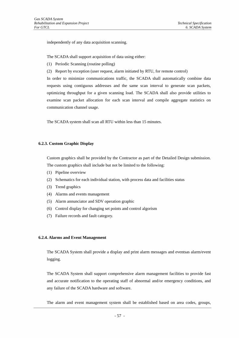
Gas SCADA System Rehabilitation and Expansion Project Technical Specification For GTCL 6. SCADA System
- 57 -
independently of any data acquisition scanning.
The SCADA shall support acquisition of data using either:
(1) Periodic Scanning (routine polling)
(2) Report by exception (user request, alarm initiated by RTU, for remote control)
In order to minimize communications traffic, the SCADA shall automatically combine data
requests using contiguous addresses and the same scan interval to generate scan packets,
optimizing throughput for a given scanning load. The SCADA shall also provide utilities to
examine scan packet allocation for each scan interval and compile aggregate statistics on
communication channel usage.
The SCADA system shall scan all RTU within less than 15 minutes.
6.2.3. Custom Graphic Display
Custom graphics shall be provided by the Contractor as part of the Detailed Design submission.
The custom graphics shall include but not be limited to the following:
(1) Pipeline overview
(2) Schematics for each individual station, with process data and facilities status
(3) Trend graphics
(4) Alarms and events management
(5) Alarm annunciator and SDV operation graphic
(6) Control display for changing set points and control algorism
(7) Failure records and fault category.
6.2.4. Alarms and Event Management
The SCADA System shall provide a display and print alarm messages and eventsas alarm/event
logging.
The SCADA System shall support comprehensive alarm management facilities to provide fast
and accurate notification to the operating staff of abnormal and/or emergency conditions, and
any failure of the SCADA hardware and software.
The alarm and event management system shall be established based on area codes, groups,
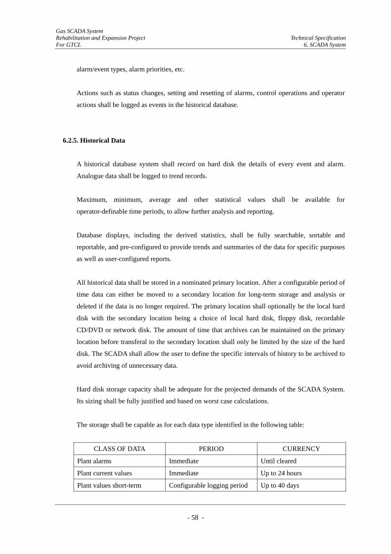
Gas SCADA System Rehabilitation and Expansion Project Technical Specification For GTCL 6. SCADA System
- 58 -
alarm/event types, alarm priorities, etc.
Actions such as status changes, setting and resetting of alarms, control operations and operator
actions shall be logged as events in the historical database.
6.2.5. Historical Data
A historical database system shall record on hard disk the details of every event and alarm.
Analogue data shall be logged to trend records.
Maximum, minimum, average and other statistical values shall be available for
operator-definable time periods, to allow further analysis and reporting.
Database displays, including the derived statistics, shall be fully searchable, sortable and
reportable, and pre-configured to provide trends and summaries of the data for specific purposes
as well as user-configured reports.
All historical data shall be stored in a nominated primary location. After a configurable period of
time data can either be moved to a secondary location for long-term storage and analysis or
deleted if the data is no longer required. The primary location shall optionally be the local hard
disk with the secondary location being a choice of local hard disk, floppy disk, recordable
CD/DVD or network disk. The amount of time that archives can be maintained on the primary
location before transferal to the secondary location shall only be limited by the size of the hard
disk. The SCADA shall allow the user to define the specific intervals of history to be archived to
avoid archiving of unnecessary data.
Hard disk storage capacity shall be adequate for the projected demands of the SCADA System.
Its sizing shall be fully justified and based on worst case calculations.
The storage shall be capable as for each data type identified in the following table:
CLASS OF DATA PERIOD CURRENCY
Plant alarms Immediate Until cleared
Plant current values Immediate Up to 24 hours
Plant values short-term Configurable logging period Up to 40 days
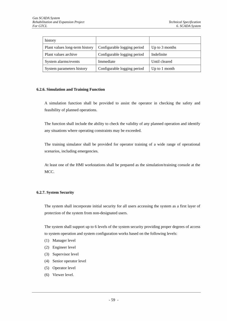
Gas SCADA System Rehabilitation and Expansion Project Technical Specification For GTCL 6. SCADA System
- 59 -
history
Plant values long-term history Configurable logging period Up to 3 months
Plant values archive Configurable logging period Indefinite
System alarms/events Immediate Until cleared
System parameters history Configurable logging period Up to 1 month
6.2.6. Simulation and Training Function
A simulation function shall be provided to assist the operator in checking the safety and
feasibility of planned operations.
The function shall include the ability to check the validity of any planned operation and identify
any situations where operating constraints may be exceeded.
The training simulator shall be provided for operator training of a wide range of operational
scenarios, including emergencies.
At least one of the HMI workstations shall be prepared as the simulation/training console at the
MCC.
6.2.7. System Security
The system shall incorporate initial security for all users accessing the system as a first layer of
protection of the system from non-designated users.
The system shall support up to 6 levels of the system security providing proper degrees of access
to system operation and system configuration works based on the following levels:
(1) Manager level
(2) Engineer level
(3) Supervisor level
(4) Senior operator level
(5) Operator level
(6) Viewer level.
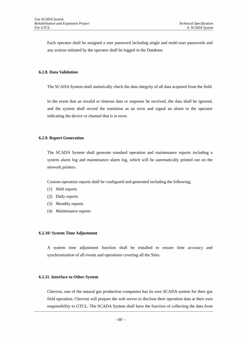
Gas SCADA System Rehabilitation and Expansion Project Technical Specification For GTCL 6. SCADA System
- 60 -
Each operator shall be assigned a user password including single and multi-user passwords and
any actions initiated by the operator shall be logged in the Database.
6.2.8. Data Validation
The SCADA System shall statistically check the data integrity of all data acquired from the field.
In the event that an invalid or timeout data or response be received, the data shall be ignored,
and the system shall record the transition as an error and signal an alarm to the operator
indicating the device or channel that is in error.
6.2.9. Report Generation
The SCADA System shall generate standard operation and maintenance reports including a
system alarm log and maintenance alarm log, which will be automatically printed out on the
network printers.
Custom operation reports shall be configured and generated including the following;
(1) Shift reports
(2) Daily reports
(3) Monthly reports
(4) Maintenance reports
6.2.10/ System Time Adjustment
A system time adjustment function shall be installed to ensure time accuracy and
synchronization of all events and operations covering all the Sites.
6.2.11. Interface to Other System
Chevron, one of the natural gas production companies has its own SCADA system for their gas
field operation. Chevron will prepare the web server to disclose their operation data at their own
responsibility to GTCL. The SCADA System shall have the function of collecting the data from
Gas SCADA System Rehabilitation and Expansion Project Technical Specification For GTCL 6. SCADA System
- 61 -
Chevron’s web server through the secured lease line.
6.2.12. Pipeline Operations Application Software
Pipeline operations application software shall be provided to support “on-line leak detection”
and “load balancing and supply scheduling”.
The application software shall be based around a real time dynamic model of the gas pipeline
network covered by the Project which shall provide a kernel for any additional functionality
required.
(1) On-line leak detection
The leak detection method used shall calculate and monitor the line pack, pressure profile
and rate of change of pressure of the calculation points on the pipeline.
(2) Load balancing and supply scheduling
Application software shall be provided for load balancing and supply scheduling.
Load balancing software shall allow the monitoring of the gas pipeline network covered by
the Project parameters and calculation of line pack and pressure to allow them to be
maintained within agreed operational bands.
Supply scheduling shall allow the planning of gas production and consumption based on
nominations to enable the requirements of producers and consumers to be met.
Load balancing and supply scheduling shall be carried out on at least an hourly basis.
The load balancing and scheduling software shall assist in the assessment of the effects of
nominations in keeping the gas pipeline network covered by the Project in balance.
6.3. SCADA System Equipment Requirements
6.3.1. Server
The SCADA servers to be installed in the MCC and the ACC shall be provided to communicate
with each RTU and be capable of performing the following tasks and functions:
(1) Real-time database handling
(2) Event database handling
(3) Ttrending
Gas SCADA System Rehabilitation and Expansion Project Technical Specification For GTCL 6. SCADA System
- 62 -
(4) Hhistorical data archiving
(5) Engineering tool
(6) Alarm management
(7) Reporting
All servers shall form part of a redundant pair arrangement and be equipped with full
Human-Machine Interface activities.
The number of servers to be provided shall be such as will achieve maximum availability and
reliability of operations, with no single point of failure.
6.3.2. HMI Workstations
The main operator interface of the SCADA System for control, monitoring and shutdown shall
be a software application. The application shall operate on personal or desktop computers within
local workstations. These workstations shall be ‘clients’ to the main system communication
controllers or ‘servers’.
The number of client operator stations shall be such as will be capable of fully controlling and
monitoring all likely operating scenarios within the facilities.
6.3.3. Printers
High quality monochrome (black and white) laser printers and color laser printers, with a
minimum throughput rate of 20 pages a minute, shall be provided for printing reports at the MCC
and the ACC. Each printer shall be accessible from all workstations to provide flexible use of
network printers connected to the LAN.
6.3.4. LAN
Interconnection within the SCADA System at the MCC and the ACC shall be supported by a
redundant LAN, which shall conform to a recognized international open standard.
Gas SCADA System Rehabilitation and Expansion Project Technical Specification For GTCL 6. SCADA System
- 63 -
6.3.5. Large Screen Monitor
A flat panel large screen monitor which will give an overview of information to all personnel in
the MCC and the ACC shall be provided.
The monitor shall have a picture size of no less than 50 inches diagonal with a screen aspect
ratio chosen to accommodate both the video formats and graphics resolution selected.
6.3.6. UPS at Operating Company Terminal Site
UPS shall have the capacity of30 minutes power supply during power failure for proposed OCT
equipment.
6.4. RTU Equipment Requirements
6.4.1. General
The RTU is a device that is required to be installed at each Site to collect data, code the data into
a format that is transmittable and transmit the data to the MCC and the ACC. RTUs shall also
collect information from the MCC and ACC and implement processes that are directed by the
MCC and ACCS. RTUs shall be equipped with input channels for sensing or metering, output
channels for control and a communication port.
RTUs shall be outdoor self-stand type data acquisition and control units, with IP65 enclosure.
RTUs shall be installed under the existing sunshades at the Existing Sites and new sunshades
shall be prepared by the Project at the Additional Sites for weather protection.
RTUs shall have the following attributes
(1) Backup batteries (24 hours)
(2) IS barrier and lightning protection
(3) Dew condensation prevention
(4) I/O interface,
(5) AGA report standard compatible
(6) Data links to other systems/packages using serial links
(7) Display monitor for process data monitoring at specified site (refer to Section 6.5.8)
Gas SCADA System Rehabilitation and Expansion Project Technical Specification For GTCL 6. SCADA System
- 64 -
(8) Data storage (at least 3 days) during server communication failure
(9) Electric outlet (AC 230V) for maintenance
(10) DC power supply unit for field instruments and radio equipment
6.4.2. Electric Power
The following types of power supply will be applied for RTUs. Applicable power supplies are
referred to in the RTU List (Appendix-3).
(1) Existing AC 230V
(2) Replace of existing solar panel
(3) Preparation of new solar power system
All RTUs shall be provided with battery backup systems to supply emergency loads (RTU and
radio equipment for communication network) for a period of 24 hours under the condition of loss
of AC commercial power.
Detailed specifications for RTU electric power are indicated in Section 9 “Electrical Works
Requirements”.
6.4.3. IS Barrier and Lightning Protection
All input signals shall be provided with IS barrier and lightning protection.
6.4.4. Dew Condensation Prevention
The Bangladesh climate during the season of high humidity and high ambient temperature can
result in condensation occurring within the RTU. To mitigate this, condensation prevention shall
be provided in the RTU.
For the solar powered RTU, condensation prevention may be ignored due to power supply
condition.
Gas SCADA System Rehabilitation and Expansion Project Technical Specification For GTCL 6. SCADA System
- 65 -
6.4.5. I/O Interface
I/O interfacing function shall be provided for the RTUs according to the I/O List (Appendix-4).
The number of I/Os for each RTU shall be determined in accordance with the said I/O list and
shall have a spare capacity of 25%.
6.4.6. AGA Report Standard Compatible
RTUs installed at orifice metering site and turbine metering site shall calculate the gas volume
flow with the use of formula certified by the AGA gas report No.3 and No. 7 respectively.
The following parameters as a minimum for gas volume calculation can be inputted at
MCC/ACC and the display mounted on the RTU.
(1) Orifice bore diameter
(2) Pipe bore diameter
(3) Specific gravity
(4) Bas pressure
(5) Base Temperature
(6) Mol% of CO2
(7) Mol% of Nitrogen
(8) Bas Compressibility
6.4.7. Data Link to Other Systems Using Serial Links
The site “20-BKB-702, Bangura Gas Field” is operated by Tullow Bangladesh Company Ltd.
Tullow uses a PLC (Allen-Bradley Model # Control Logic 5562) and HMI software for
monitoring and control of this site.
The RTU shall have sufficient interface functionality to communicate with Tullow’s PLC.
6.4.8. Display Monitor for Process Data Monitoring
RTUs at the following sites shall be equipped with display to monitor the process data limited to
Gas SCADA System Rehabilitation and Expansion Project Technical Specification For GTCL 6. SCADA System
- 66 -
the site covered by each RTU respectively. The operator can input the parameters of gas volume
calculation through these monitors and from HMI workstations at MCC/ACC.
Code Site
10-ASH-400 Ashuganj
20-BKB-101 Kutombopur
20-FAU-100 Faujdarhat
20-MIR-401 Barakubundu TBS
30-PBG-401 CGS Aminbazar (out)
30-PBG-402 CGS Ashulia (out)
40-ELE-500 Elenga
40-MHD-500 Monohordi
6.4.9. Data Storage during Server Communication Failure
At each RTU to be installed in the Site, a database storage facility shall be provided to store all
acquired data from field, control tuning data and other historical operating data of every 30
minutes as a minimum, for a period of 15 days.
The database of the RTU shall be configured according to the master database to be provided for
the MCC and the ACC to enable recovery of missing data at the master database in the event of
communication failure between the RTUs and the MCC and the ACC.
6.4.10. Electric Outlet for Maintenance
An AC 230V electric outlet shall be prepared in the RTU for maintenance except solar powered
RTUs.
6.4.11. DC Power Supply Unit
The RTUs shall be equipped with 24 VDC power supply system for the field instruments to be
designed based on the power load for power system sizing and distribution design.
Gas SCADA System Rehabilitation and Expansion Project Technical Specification For GTCL 6. SCADA System
- 67 -
6.4.12. RTU Maintenance Terminal
The Contractor shall provide four laptop computers suitable for the programming and
interrogation of RTUs. These shall be capable of preparing and modifying sequence programs,
editing RTU point and alarm configuration and displaying/retrieving historical data and current
data from RTU.
The RTU maintenance terminal shall be suitable for use in the environmental conditions of
temperature and humidity specified in the general equipment requirements for outdoor
Bangladesh.
Gas SCADA System Rehabilitation and Expansion Project Technical Specification For GTCL 7. Communication System
- 68 -
7. Communication System
7.1. System Configuration Requirements
7.1.1. General
(1) The Communication System shall be connected to the Master Telemetry Stations (20
stations), the Slave Telemetry Stations (81 + 7 upcoming stations), Operating Company
Terminal (9 stations), Chevron’s server at Chevron Head Office and MCC/ACC. The
system shall be composed of the following links and systems:
1) Leased E1 circuits from service provider’s network between MCC/ACC and Access
Points (AP) of provider’s network
2) IP radio link between AP and Master Telemetry Station (MTS)
3) IP radio link between MTS and OCT as well as Chevron’s server
4) Telemetry radio link between the MTS and Slave Telemetry Station (STS)
5) IP PBX System
(2) The Communication System shall use IP/Ethernet signal transmission system and has
enough capacity for data transmission increase in future.
(3) The Communication System is a closed network, however some port of the network will be
connected to WAN. Therefore security measures shall be required.
(4) The Contractor shall be responsible for the following aspects for Communication System
design:
1) Network design
2) IP radio path design
3) VoIP(IP PBX) configuration design
(5) The contract for the lease of E1 circuits from service provider’s network shall be made
between GTCL and the provider (BTCL is recommended). The Contractor shall be
responsible to provide GTCL with technical assistance for their Contract agreement as well
as necessary coordination during implementation of the Works. The configuration of leased
E1 circuits is illustrated in Figure 7.1.
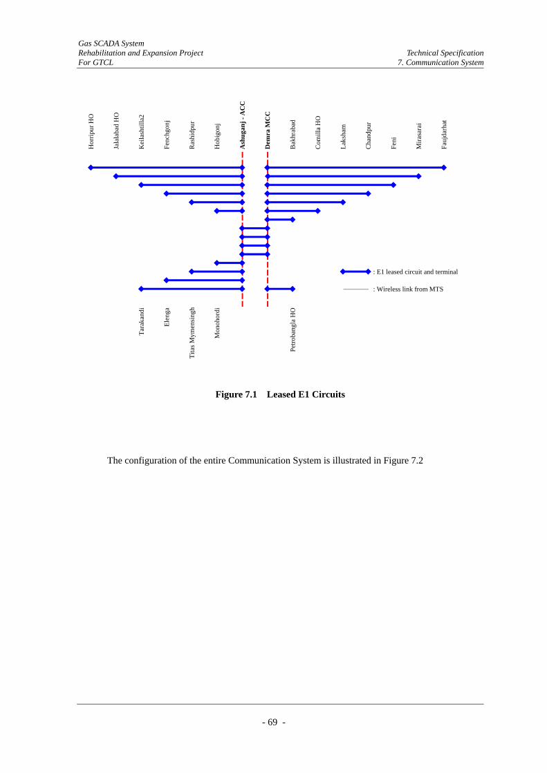
Gas SCADA System Rehabilitation and Expansion Project Technical Specification For GTCL 7. Communication System
- 69 -
Petro
bang
la H
O
: E1 leased circuit and terminal
: Wireless link from MTS
Tara
kand
i
Elen
ga
Tita
s Mym
ensi
ngh
Mon
ohor
di
Feni
Mira
sara
i
Fauj
darh
at
Bak
hrab
ad
Com
illa
HO
Laks
ham
Cha
ndpu
r
Ras
hidp
ur
Hob
igon
j
Ash
ugan
j - A
CC
Dem
ra M
CC
Hor
ripur
HO
Jala
laba
d H
O
Kei
lash
tilla
2
Fenc
hgon
j
Figure 7.1 Leased E1 Circuits
The configuration of the entire Communication System is illustrated in Figure 7.2

Gas SCADA System Rehabilitation and Expansion Project Technical Specification For GTCL 7. Communication System
- 70 -
(Sanghu on shore P.P.)
Keilashtilla2
Horipur HO
Fenchugonj
Jalalabad HO
Hobigonji
Rashidpur
Ashuganji
MonohordiElenga
Tarakandi
Mirasarai
Demra
Bakhrabad
Laksham Chandpur
Feni
Faujdarhat
Comilla
Mymensingh
Provider’sNetwork & AP
Wireless Link between MTS & AP
Wireless Link between OCT/Server & MTS
: Master Telemetry Station
: OCT(Operating Company Terminal)
Petrobangla HO
: Telemetry Slave Station(RTU)
TITAS HO
(SGFL)
(JGTDSL)
(TGTDSL)
(BGFL)
(BGFCL)
(10.5)
(10.2)
(2.6)
(2.0)
(15.0)
(1.2)
(1.0)(9.4)
(3.5)
(12.6)(1.5) (1.0)
(3.7)
(0.1) (1.5)
(2.9)
(10.8)
(1.8)
(xx) : Radio link distance(km)
(0.2)
(1.6)
(4.7)
(10.0)
(12.1)
(9)
(2)
(1)
(4)
(6)
(2)
(1)
(12)
(8)
(14)(3)
(1)
(1)
(3)
(3) (5)
Figure 7.2 Entire Communication System
(KGDCL)
Chevron HO (Server/OCT)
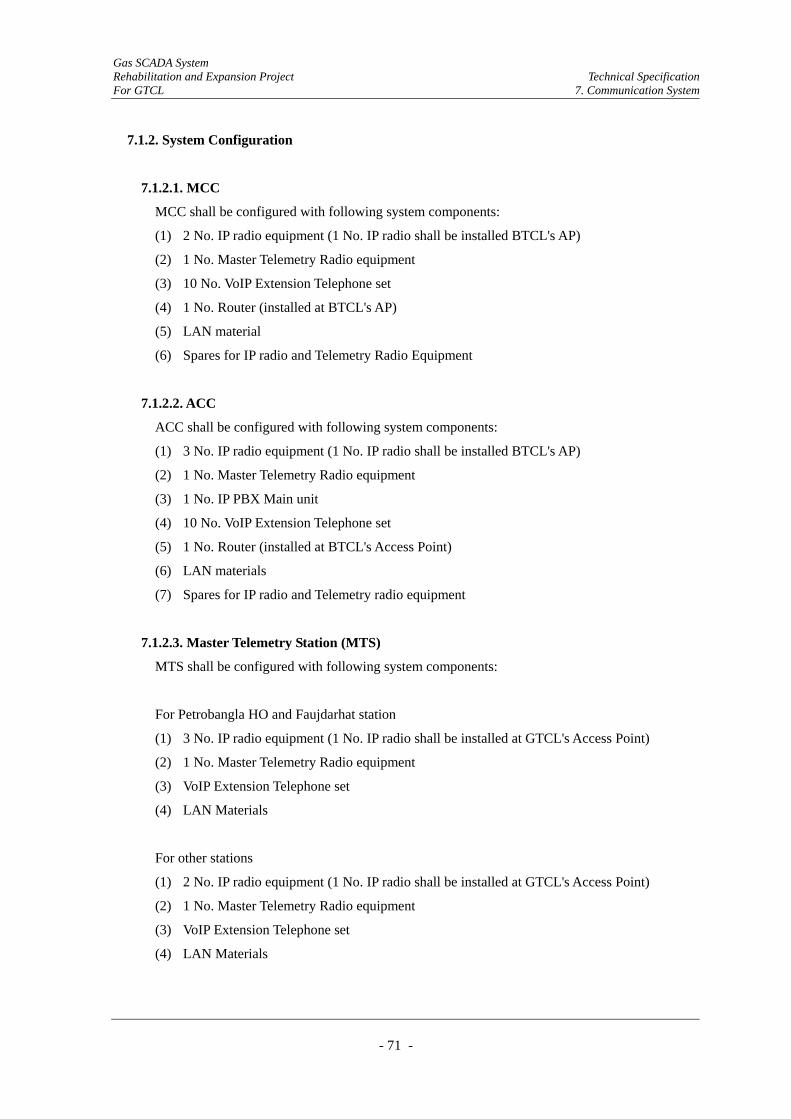
Gas SCADA System Rehabilitation and Expansion Project Technical Specification For GTCL 7. Communication System
- 71 -
7.1.2. System Configuration
7.1.2.1. MCC
MCC shall be configured with following system components:
(1) 2 No. IP radio equipment (1 No. IP radio shall be installed BTCL's AP)
(2) 1 No. Master Telemetry Radio equipment
(3) 10 No. VoIP Extension Telephone set
(4) 1 No. Router (installed at BTCL's AP)
(5) LAN material
(6) Spares for IP radio and Telemetry Radio Equipment
7.1.2.2. ACC
ACC shall be configured with following system components:
(1) 3 No. IP radio equipment (1 No. IP radio shall be installed BTCL's AP)
(2) 1 No. Master Telemetry Radio equipment
(3) 1 No. IP PBX Main unit
(4) 10 No. VoIP Extension Telephone set
(5) 1 No. Router (installed at BTCL's Access Point)
(6) LAN materials
(7) Spares for IP radio and Telemetry radio equipment
7.1.2.3. Master Telemetry Station (MTS)
MTS shall be configured with following system components:
For Petrobangla HO and Faujdarhat station
(1) 3 No. IP radio equipment (1 No. IP radio shall be installed at GTCL's Access Point)
(2) 1 No. Master Telemetry Radio equipment
(3) VoIP Extension Telephone set
(4) LAN Materials
For other stations
(1) 2 No. IP radio equipment (1 No. IP radio shall be installed at GTCL's Access Point)
(2) 1 No. Master Telemetry Radio equipment
(3) VoIP Extension Telephone set
(4) LAN Materials
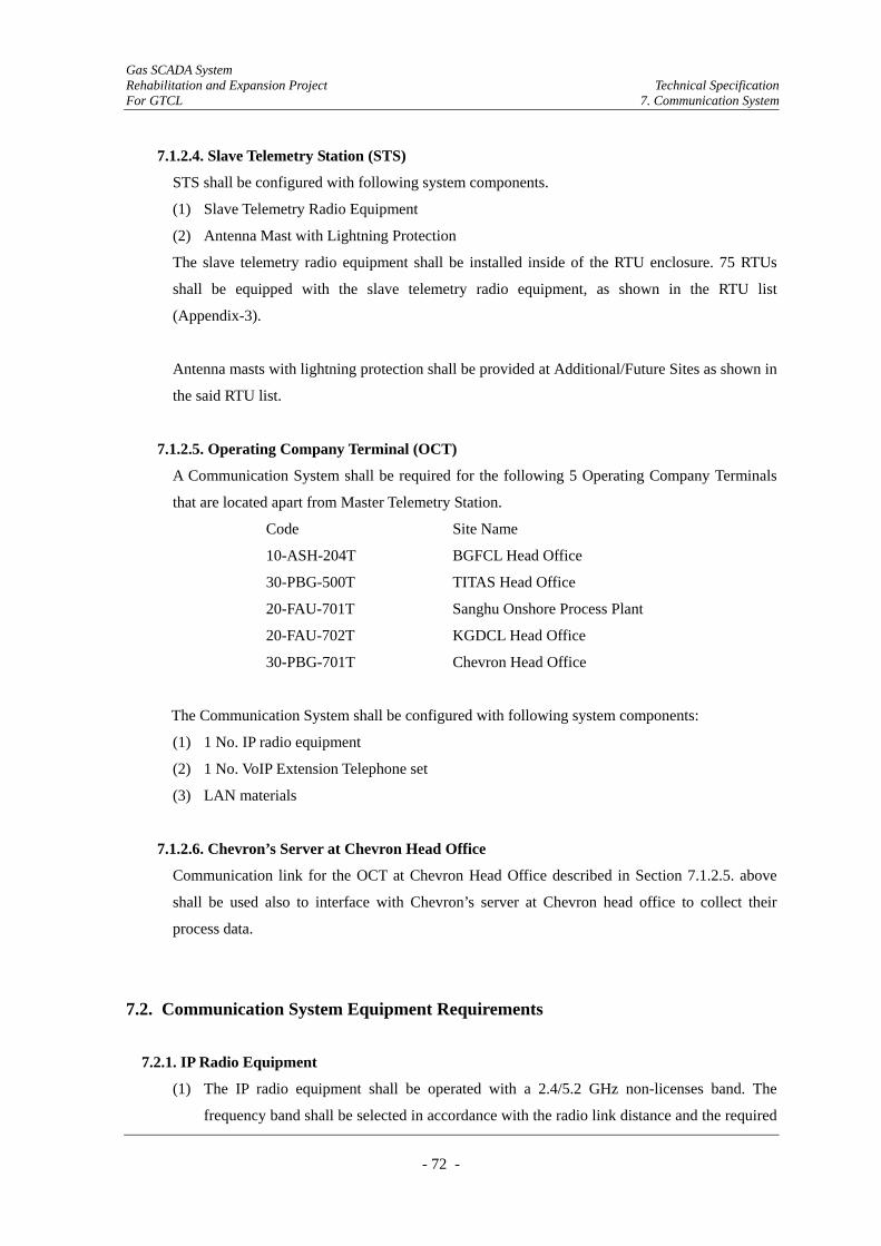
Gas SCADA System Rehabilitation and Expansion Project Technical Specification For GTCL 7. Communication System
- 72 -
7.1.2.4. Slave Telemetry Station (STS)
STS shall be configured with following system components.
(1) Slave Telemetry Radio Equipment
(2) Antenna Mast with Lightning Protection
The slave telemetry radio equipment shall be installed inside of the RTU enclosure. 75 RTUs
shall be equipped with the slave telemetry radio equipment, as shown in the RTU list
(Appendix-3).
Antenna masts with lightning protection shall be provided at Additional/Future Sites as shown in
the said RTU list.
7.1.2.5. Operating Company Terminal (OCT)
A Communication System shall be required for the following 5 Operating Company Terminals
that are located apart from Master Telemetry Station.
Code Site Name
10-ASH-204T BGFCL Head Office
30-PBG-500T TITAS Head Office
20-FAU-701T Sanghu Onshore Process Plant
20-FAU-702T KGDCL Head Office
30-PBG-701T Chevron Head Office
The Communication System shall be configured with following system components:
(1) 1 No. IP radio equipment
(2) 1 No. VoIP Extension Telephone set
(3) LAN materials
7.1.2.6. Chevron’s Server at Chevron Head Office
Communication link for the OCT at Chevron Head Office described in Section 7.1.2.5. above
shall be used also to interface with Chevron’s server at Chevron head office to collect their
process data.
7.2. Communication System Equipment Requirements
7.2.1. IP Radio Equipment
(1) The IP radio equipment shall be operated with a 2.4/5.2 GHz non-licenses band. The
frequency band shall be selected in accordance with the radio link distance and the required
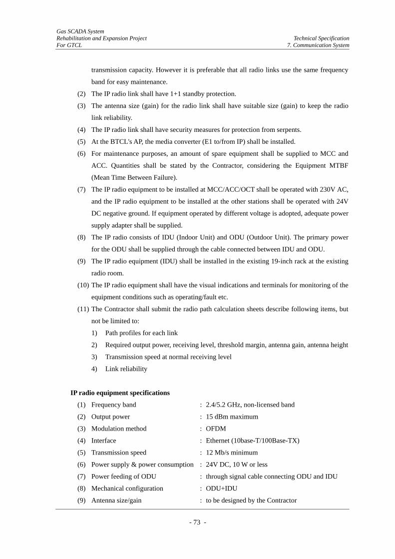
Gas SCADA System Rehabilitation and Expansion Project Technical Specification For GTCL 7. Communication System
- 73 -
transmission capacity. However it is preferable that all radio links use the same frequency
band for easy maintenance.
(2) The IP radio link shall have 1+1 standby protection.
(3) The antenna size (gain) for the radio link shall have suitable size (gain) to keep the radio
link reliability.
(4) The IP radio link shall have security measures for protection from serpents.
(5) At the BTCL's AP, the media converter (E1 to/from IP) shall be installed.
(6) For maintenance purposes, an amount of spare equipment shall be supplied to MCC and
ACC. Quantities shall be stated by the Contractor, considering the Equipment MTBF
(Mean Time Between Failure).
(7) The IP radio equipment to be installed at MCC/ACC/OCT shall be operated with 230V AC,
and the IP radio equipment to be installed at the other stations shall be operated with 24V
DC negative ground. If equipment operated by different voltage is adopted, adequate power
supply adapter shall be supplied.
(8) The IP radio consists of IDU (Indoor Unit) and ODU (Outdoor Unit). The primary power
for the ODU shall be supplied through the cable connected between IDU and ODU.
(9) The IP radio equipment (IDU) shall be installed in the existing 19-inch rack at the existing
radio room.
(10) The IP radio equipment shall have the visual indications and terminals for monitoring of the
equipment conditions such as operating/fault etc.
(11) The Contractor shall submit the radio path calculation sheets describe following items, but
not be limited to:
1) Path profiles for each link
2) Required output power, receiving level, threshold margin, antenna gain, antenna height
3) Transmission speed at normal receiving level
4) Link reliability
IP radio equipment specifications
(1) Frequency band : 2.4/5.2 GHz, non-licensed band
(2) Output power : 15 dBm maximum
(3) Modulation method : OFDM
(4) Interface : Ethernet (10base-T/100Base-TX)
(5) Transmission speed : 12 Mb/s minimum
(6) Power supply & power consumption : 24V DC, 10 W or less
(7) Power feeding of ODU : through signal cable connecting ODU and IDU
(8) Mechanical configuration : ODU+IDU
(9) Antenna size/gain : to be designed by the Contractor

Gas SCADA System Rehabilitation and Expansion Project Technical Specification For GTCL 7. Communication System
- 74 -
7.2.2. Telemetry Radio Equipment
(1) The telemetry radio equipment shall be operated in 400 MHz band.
(2) The master telemetry radio equipment shall have 1+1 standby protection.
(3) The master/slave telemetry radio equipment shall have IP/Ethernet interface port.
(4) To reduce the power consumption, the transmitter output power shall be adjusted depending
on the radio link distance.
(5) The rise up time for the transmitter of slave telemetry radio equipment shall be as short as
possible for the polling operation method. The contractor shall state the rise up time, and
also state whether the master station transmitter can operates intermittently.
(6) As distances of some links between MTS and STS are over 30 km, the Contractor shall
select suitable antenna sizes for STS and suitable antenna heights for MTS.
(7) The telemetry radio equipment to be installed at MCC/ACC shall be operated with AC
230V AC. The telemetry radio equipment to be installed at the other stations shall be
operated with 24V DC negative ground. If the equipment operated with different voltage is
adopted, adequate power supply adapter shall be supplied.
(8) The power consumption of radio equipment shall be as small as possible. The contractor
shall state the power consumption of the base/slave radio equipment.
(9) The master telemetry radio equipment shall be installed in the existing 19-inch rack at the
existing radio room.
(10) An antenna mast with lightning protection for the slave telemetry radio equipment as well
as for RTUs shall be provided. The Contractor shall decide its height in accordance with the
radio path calculation.
(11) The Contractor shall submit the radio path calculation sheet for the following 4 links:
1) Jalalabad H.O (MTS) – Devpur DRS (4.5 km)
2) Rashidpur (MTS) - VS M (11.2 km)
3) Mirasarai (MTS) – Semutang Gas Field (21.5 km)
4) Monohordi (MTS) - Joydepur CGS (32.9 km)
The calculation sheets shall include the following items, but not be limited to:
1) Path profiles
2) Required output power, receiving level, threshold margin, antenna gain, antenna height
3) Transmission speed at normal receiving level
4) Link reliability
(12) Telemetry scanning method
1) Each transmitter of master telemetry radio equipment shall be continuously operated
to enable the telemetry system to sequentially address the STSs.
Gas SCADA System Rehabilitation and Expansion Project Technical Specification For GTCL 7. Communication System
- 75 -
2) The slave telemetry radio equipment receives its own address, and the transmitter of
master telemetry radio equipment shall be enabled to send data from RTU to the
SCADA System.
3) Each transmitter of slave telemetry radio equipment shall be activated only when the
slave telemetry radio equipment is addressed.
Telemetry radio equipment specifications
(1) Operating frequency band : 400 MHz band
(2) Operation mode : Simplex, half-duplex
(3) Protection : 1+1 Standby protection (Master)
: 1+0 standby protection (Slave)
(4) Output power : 5W max.
(5) Modulation method : Digital, CPFSK
(6) Interface : Ethernet (10Base-T/100Base-TX)
(7) Transmission speed : 4.8 kb/s minimum
(8) Power supply & power consumption : 24V, 40W or less (continuous operation TX/RX),
2W or less (RX only)
(9) Transmitter rise up time : 5 ms typical,
(the contractor shall design the rise up time of the
transmitter to be offered)
(10) Antenna size/gain : Omni-directional at master, directional at slave
station. The gain of antennae shall be designed by
the Contractor.
(11) Antenna mast at Additional Sites
1) Height, strength and material : to be designed by the Contractor
2) Foundation : to be designed and constructed by the Contractor
3) Lightning system : Lightning rod shall connect to RTU's earthing
system.
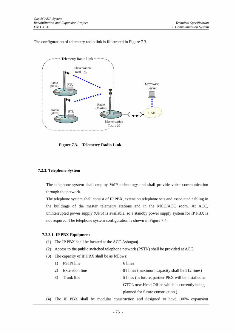
Gas SCADA System Rehabilitation and Expansion Project Technical Specification For GTCL 7. Communication System
- 76 -
The configuration of telemetry radio link is illustrated in Figure 7.3.
7.2.3. Telephone System
The telephone system shall employ VoIP technology and shall provide voice communication
through the network.
The telephone system shall consist of IP PBX, extension telephone sets and associated cabling in
the buildings of the master telemetry stations and in the MCC/ACC room. At ACC,
uninterrupted power supply (UPS) is available, so a standby power supply system for IP PBX is
not required. The telephone system configuration is shown in Figure 7.4.
7.2.3.1. IP PBX Equipment
(1) The IP PBX shall be located at the ACC Ashuganj.
(2) Access to the public switched telephone network (PSTN) shall be provided at ACC.
(3) The capacity of IP PBX shall be as follows:
1) PSTN line : 6 lines
2) Extension line : 81 lines (maximum capacity shall be 512 lines)
3) Trunk line : 5 lines (in future, partner PBX will be installed at
GTCL new Head Office which is currently being
planned for future construction.)
(4) The IP PBX shall be modular construction and designed to have 100% expansion
Slave station Total : 75
LAN
MCC/ACCServer
RTU Radio (slave)
Radio (Master)
RTU Radio (slave)
Telemetry Radio Link
Figure 7.3. Telemetry Radio Link
Master stationTotal : 20
Gas SCADA System Rehabilitation and Expansion Project Technical Specification For GTCL 7. Communication System
- 77 -
capability.
(5) The IP PBX shall be non blocking digital switches, operating under stored program control.
(6) All common control equipment shall be duplicated.
(7) PSTN connection
1) In the case where the PSNT connection is a digital circuit, the interface condition shall
be compliant with relevant ITU-T Rec. and other regulations.
2) The IP PBX shall have facilities to restrict dialing access from any telephone extension
to the PSTN.
3) Access to the PSTN shall be done through direct dialing where configured, and shall
be permitted to the selected extension lines.
(8) Supervisory function
1) A supervisory system shall be provided for IP PBX that allows the performance to be
analyzed as well as providing configuration facilities and fault information and
diagnostics.
2) The IP PBX shall prepare, store and collate information on call logging, traffic
analysis and fault analysis. A hard copy printout shall be available at IP PBX
installation on dedicated printers.
(9) The exact quantities and locations of the VoIP extension telephone set are shown in Figure
7.4.
IP PBX equipment specifications
(1) Outside lines : 16 minimum
(2) Extension lines : 512 maximum
(3) Applications : to be designed by the Contractor (Voice mail,
Automated call, Distribution, Group hunting etc.)
(4) Power supply : AC 230V, single phase
(5) Backup battery : Not required
(6) Mechanical construction : to be equipped on 19 inches rack, the Contractor
shall design the height of the rack.
Extension Telephone set specifications
(1) Operation : VoIP on LAN
(2) Interface : RJ-45 (10Base-T/100Base-TX)
(3) Line key : 6 lines maximum
(4) Speaker phone : required
(5) Display : LED's display
(6) Applications : to be designed by the Contractor

Gas SCADA System Rehabilitation and Expansion Project Technical Specification For GTCL 7. Communication System
- 78 -
(7) Power supply : AC 230V, power adapter shall be provided
7.2.3.2. Telephone cabling
The contractor shall be responsible for the installation of telephones and associated cabling
inside of the room at MCC/ACC and also inside the radio building at MTS. The telephone
cabling shall be made of Ethernet cable.
7.2.3.3. Maintenance PC
The PC for the maintenance purpose shall be supplied. It shall be able to interface with IP PBX
in order to upgrade or renew the programs installed in IP PBX memory.
Figure 7.4 IP PBX System
7.2.4. Network system
7.2.4.1. Media converter
(1) A media converter (IP/Ethernet to/from E1) shall be installed at BTCL's AP.
(2) The media converter shall be operated with 24V DC negative ground. If the equipment
operated with different voltage is adopted, a DC/DC converter shall be supplied.
Jala
bad(
TGTD
SL)
(OC
T)
Fenc
hugo
nji
Hor
ipur
Hob
igon
ji
Mon
ohor
di
Elen
ga
Tara
kand
i
Mym
ensi
ngh
Ash
ugan
j(A
CC
)
Dem
ra(M
CC
)
Laks
ham
Petro
bang
la H
O
Feni
Mira
sara
i
Fauj
darh
at
Cha
ndpu
r
Kei
lash
itilla
Ras
hidp
ur
Com
ila
TITA
S H
O(T
GTD
SL)
(OC
T)
BG
FCL (
Ash
ugan
j)
IP P
BX
GTCL NETWORK
6 x PSTN lines
(20)
(2) (1) (3) (2) (2) (3) (1) (20) (2) (2) (2) (1) (2) (1) (2) (2) (2) (2) (2) (3)
: Extension line (VoIP Telephone)
(Max: 512 Ext. lines) Sa
hghu
on
shor
e P.
P
(1)
Bak
hrab
ad
(3)

Gas SCADA System Rehabilitation and Expansion Project Technical Specification For GTCL 7. Communication System
- 79 -
(3) A Router or HUB which converts IP/Ethernet to/from E1 can be offered.
Media converter specifications
(1) Converting signal protocol : IP/Ethernet to/from E1(2Mb/s)
(2) Number of required port : For MCC's AP
3 nos. IP/Ethernet: 12 nos. E1 Min.
: For ACC's AP
3 nos. IP/Ethernet: 14 nos. E1 Min.
: For other 18 AP
1 no. IP/Ethernet: 1 no. E1 Min.
(3) E1 signal format : HDB-3
(4) Interface connector : RJ-45 for IP/Ethernet side
BNC-R for E1 side
(5) Power supply : 24V DC negative ground
(6) Power consumption : to be designed by the Contractor
(7) Mechanical construction : to be installed on a 19-inch rack
7.2.4.2. HUB/Router
(1) To connect with the branching network, a HUB or Router shall be provided to each MTS
and MCC/ACC.
(2) The Contractor shall select an adequate branching device from the HUB or Router to get
the best performance of the network.
(3) The HUB/Router to be installed at MCC/ACC shall be operated with 230V AC. The
HUB/Router to be installed at the other stations shall be operated with 24V DC negative
ground. If the equipment operated with different voltage is adopted, an adequate power
supply adapter shall be supplied.
HUB specifications
(1) Number of port : 5 minimum
(2) LAN interface : 10Base-T, 100Base-TX, 1000Bae-T
(3) Switching data transfer method : Store and forward
(4) Access method : CSMA/CD
(5) Address table : MAC address, 1,000 (min) address, self learning
(6) Interface connector : RJ-45
(7) Power supply : 24V DC, negative ground
(8) Power consumption to be designed by the Contractor
Gas SCADA System Rehabilitation and Expansion Project Technical Specification For GTCL 7. Communication System
- 80 -
Router specifications
For WAN side
(1) Number of port : 1 minimum
(2) WAN interface : 10Base-T, 100Base-TX
(3) Access Method : CSMA/CD
(4) Interface connector : RJ-45
(5) Transmission speed : 10 Mb/s, 100Mb/s, auto sense
(6) IP Address acquisition : Manual/DHCP/PPPoE/IPUnnumberd
For LAN side
(7) Number of port : 4 minimum
(8) Switching data transfer method : Store and forward
(9) Address table : MAC address, 1,024 (min) address, self learning
(10) Interface connector : RJ-45
Router function
(11) Number of registry of packet filter : 32 minimum
(12) Number of registry interchangeable address (port) : 20 minimum
(13) Number of IP masquerading session : 800 minimum
(14) Number of registry routing table : 20 minimum
(15) Number of MAC address filtering : 32 minimum
(16) Number of Subnet : /24 - /30
(17) Power supply : 24V DC, negative ground
(18) Power consumption : to be designed by the Contractor
7.2.4.3. Monitor PC for Network Monitoring System (NMS)
The PC with software for NMS shall be provided at MCC and ACC.
Monitor PC for NMS specifications
(1) Type of PC : Laptop type
(2) Display size : 15 inches or more
(3) OS : Windows 7 or latest version
(4) CPU : Core_2_Duo, mobile processor or better
(5) HD capacity : 500GB or more
(6) Media Drive : Built-in, CD/DVD
7.2.4.3. LAN Cable
The Contractor shall provide the LAN cable with category-5 or higher category cable for
10Base-T, or 100Base-TX for LAN cabling.
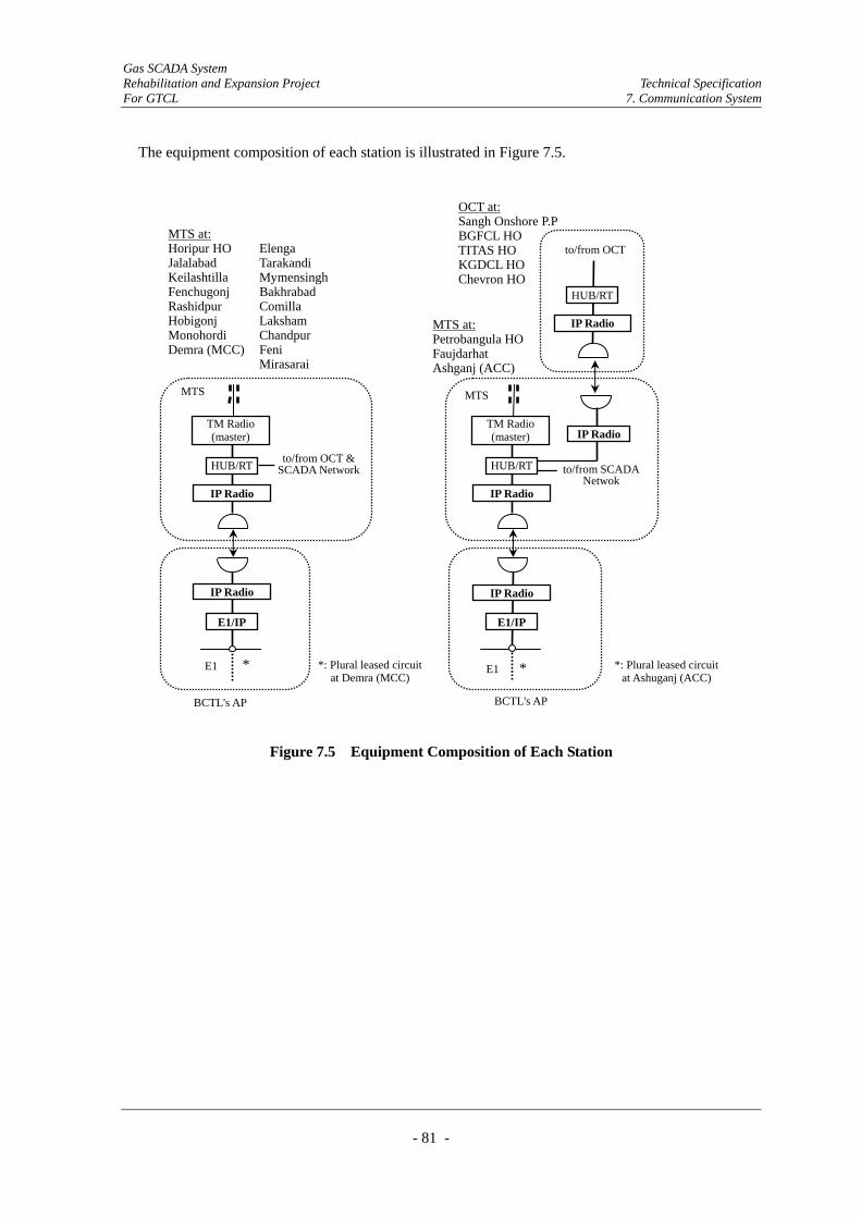
Gas SCADA System Rehabilitation and Expansion Project Technical Specification For GTCL 7. Communication System
- 81 -
The equipment composition of each station is illustrated in Figure 7.5.
Figure 7.5 Equipment Composition of Each Station
MTS at: Horipur HO Elenga Jalalabad Tarakandi Keilashtilla Mymensingh Fenchugonj Bakhrabad Rashidpur Comilla Hobigonj Laksham Monohordi Chandpur Demra (MCC) Feni Mirasarai
BCTL's AP
MTS at:Petrobangula HOFaujdarhat Ashganj (ACC)
BCTL's AP
HUB/RT
IP Radio
TM Radio (master) IP Radio
to/from SCADA Netwok
HUB/RT
IP Radio
TM Radio (master)
to/from OCT & SCADA Network
IP Radio
E1/IP
E1
MTS
* *: Plural leased circuitat Demra (MCC)
*: Plural leased circuitat Ashuganj (ACC)
E1/IP
E1
IP Radio
*
HUB/RT
IP Radio
to/from OCT
OCT at:Sangh Onshore P.PBGFCL HO TITAS HO KGDCL HO Chevron HO
MTS
Gas SCADA System Rehabilitation and Expansion Project Technical Specification For GTCL 8. Instrumentation Requirements
- 82 -
8. Instrumentation Requirements
The Contractor shall design, supply and install the following instruments:
(1) Pressure Transmitter (PT): 71
(2) Temperature Transmitter (TT): 58
(3) Differential Pressure Transmitter (PdT): 82
(4) Limit switch for valve status monitoring: 11
Instrument installation sites are shown in the RTU List (Appendix-3).
In addition to the above, the following instruments shall be supplied for spares of existing
instruments.
(1) Pressure Transmitter (PT): 15
(2) Temperature Transmitter (TT): 15
(3) Differential Pressure Transmitter(PdT): 20
8.1. General
All electronic instruments requiring separate power supply, shall generally operate on 24V DC.
Electronic transmitters shall generally be two-wire type. These shall have transmission/output
signal of 4-20 mA DC and shall be capable of delivering rated current into external load of at least
600 ohm when powered with 24 V DC nominal voltages.
8.2. Pressure Transmitters
The Contractor shall verify the process connection for pressure instruments at the sites. As a
reference, process connections for pressure instruments are normally 1/2” NPT.
At some sites, the Contractor shall make a branch on the existing impulse tubing as a tapping point
for pressure instruments. The Contractor shall survey the installation condition, make hook-up
drawings and install the pressure transmitters.
Pressure transmitters shall be electronic SMART type, two wire, loop powered at 24VDC with
4-20 mA output and an integral digital indicator meter in both MKS and FPS engineering units.
Gas SCADA System Rehabilitation and Expansion Project Technical Specification For GTCL 8. Instrumentation Requirements
- 83 -
Transmitters shall have HART protocol for digital communication.
Material for construction for wetted parts shall be SS 316L as a minimum, except where process
conditions require more stringent materials. Materials for construction shall be suitable for the
process media and based upon the piping specification.
Pressure transmitters shall have minimum accuracy ± 0.075% of the calibrated span. Transmitters
shall have independent external screws for zero and span adjustment.
8.3. Temperature Transmitters
Thermo Wells
Temperature measuring instruments shall be provided with thermo well. The boss on the pipeline
as a process connection for thermo well will be prepared by the Employer. The Contractor shall
verify the information of process connection and design suitable thermo well.
Thermo wells shall be constructed from one-piece bar stock, and machined to get a smooth and
tapered profile with no sharp edges. All insertion type temperature instruments and indicators shall
be provided with a thermo well. The thermo well immersion depth in the pipe shall be between
one-third and two-thirds of the internal diameter of the pipe.
Temperature Transmitter
Resistance temperature detectors (RTDs) shall be used for centralized and multi-point indication.
The RTDs shall be grade II, Platinum 100 ohms at 0 °C (32 °F).
A detector with head mounted transmitters shall be used. The 4-20 mA output signal must be
directly proportional and linear to temperature.
8.4. Limit Switch
Limit switches for open/close valve position indication shall be of proximity type. The switch
enclosure shall be copper free cast aluminum, weather proof (NEMA 4X) and it shall be
intrinsically safe.
Gas SCADA System Rehabilitation and Expansion Project Technical Specification For GTCL 8. Instrumentation Requirements
- 84 -
8.5. Pick up Signal from the Existing Turbine Meter
The Contractor shall supply and install a dual pulse output pickup head in place of the single pulse
output pickup in the existing turbine flow meter sensor head at sites specified in Site Information &
Scope of Work (Appendix-2). The output signal from the existing turbine flow meter shall be
cabled via junction box to RTU.
8.6. Tubing System
Stainless steel ANSI 316 tubing and fittings shall be used for the instrument gas supply distribution
system. Double compression fittings shall be used. Pneumatic devices shall be stainless steel.
Tubing shall be protected so that no galvanic corrosion will occur.
The tubing system shall be capable of continuously withstanding the design pressure and
temperature.
All materials for pressure lead pipe including valves, regulators and accessories, shall be stainless
steel. Pressure lead pipes and fittings shall be 316 SS with double compression fittings.
8.7. Junction Box
Junction boxes shall be of intrinsically safe types. Material for construction of junction boxes shall
be LM-6 cast aluminum.
Terminals shall be vibration proof, clip-on types mounted on nickel-plated steel rails complete with
end covers and clamps for each row. All terminals shall be suitable for accepting a minimum 2.5
mm2 copper conductor in general. Sizing shall be done with due consideration for accessibility and
maintenance.
Plugs shall be of Nickel plated brass.
Cable glands shall be double compression type for use with armored cables. They shall be made of
Nickel plated brass. All cable glands shall be provided with rubber cable hood. All cable glands
shall be supplied to suit the cable dimensions. Various components like rubber rings, metallic rings,
metallic cones and the outer/inner nuts, etc. shall be capable of being adjusted according to the
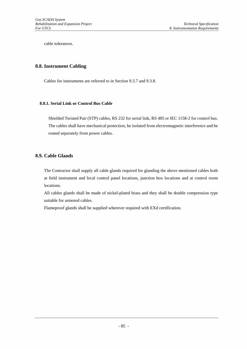
Gas SCADA System Rehabilitation and Expansion Project Technical Specification For GTCL 8. Instrumentation Requirements
- 85 -
cable tolerances.
8.8. Instrument Cabling
Cables for instruments are referred to in Section 9.3.7 and 9.3.8.
8.8.1. Serial Link or Control Bus Cable
Shielded Twisted Pair (STP) cables, RS 232 for serial link, RS 485 or IEC 1158-2 for control bus.
The cables shall have mechanical protection, be isolated from electromagnetic interference and be
routed separately from power cables.
8.9. Cable Glands
The Contractor shall supply all cable glands required for glanding the above mentioned cables both
at field instrument and local control panel locations, junction box locations and at control room
locations.
All cables glands shall be made of nickel-plated brass and they shall be double compression type
suitable for armored cables.
Flameproof glands shall be supplied wherever required with EXd certification.
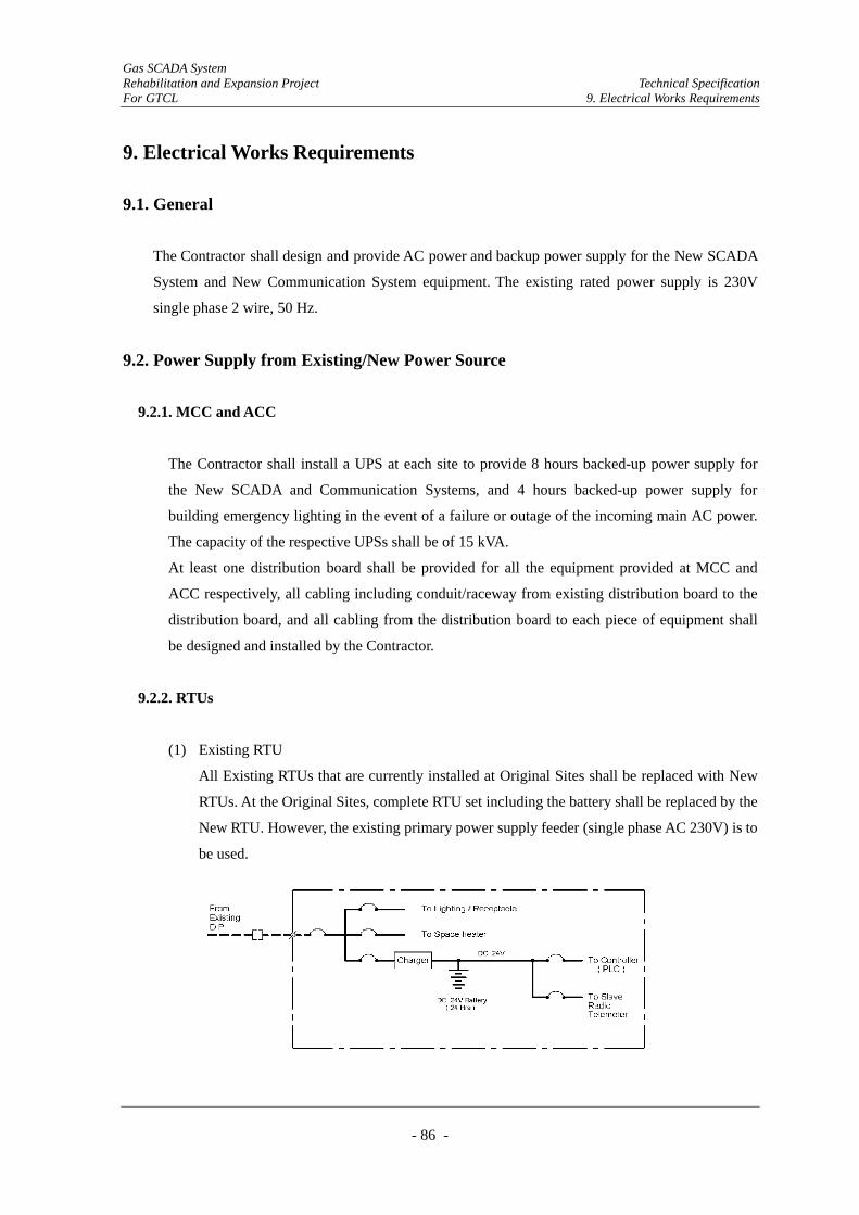
Gas SCADA System Rehabilitation and Expansion Project Technical Specification For GTCL 9. Electrical Works Requirements
- 86 -
9. Electrical Works Requirements
9.1. General
The Contractor shall design and provide AC power and backup power supply for the New SCADA
System and New Communication System equipment. The existing rated power supply is 230V
single phase 2 wire, 50 Hz.
9.2. Power Supply from Existing/New Power Source
9.2.1. MCC and ACC
The Contractor shall install a UPS at each site to provide 8 hours backed-up power supply for
the New SCADA and Communication Systems, and 4 hours backed-up power supply for
building emergency lighting in the event of a failure or outage of the incoming main AC power.
The capacity of the respective UPSs shall be of 15 kVA.
At least one distribution board shall be provided for all the equipment provided at MCC and
ACC respectively, all cabling including conduit/raceway from existing distribution board to the
distribution board, and all cabling from the distribution board to each piece of equipment shall
be designed and installed by the Contractor.
9.2.2. RTUs
(1) Existing RTU
All Existing RTUs that are currently installed at Original Sites shall be replaced with New
RTUs. At the Original Sites, complete RTU set including the battery shall be replaced by the
New RTU. However, the existing primary power supply feeder (single phase AC 230V) is to
be used.
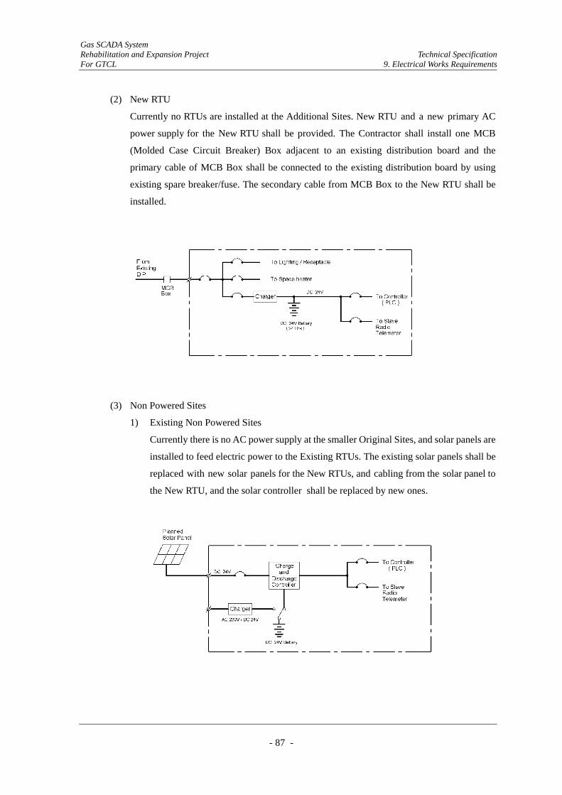
Gas SCADA System Rehabilitation and Expansion Project Technical Specification For GTCL 9. Electrical Works Requirements
- 87 -
(2) New RTU
Currently no RTUs are installed at the Additional Sites. New RTU and a new primary AC
power supply for the New RTU shall be provided. The Contractor shall install one MCB
(Molded Case Circuit Breaker) Box adjacent to an existing distribution board and the
primary cable of MCB Box shall be connected to the existing distribution board by using
existing spare breaker/fuse. The secondary cable from MCB Box to the New RTU shall be
installed.
(3) Non Powered Sites
1) Existing Non Powered Sites
Currently there is no AC power supply at the smaller Original Sites, and solar panels are
installed to feed electric power to the Existing RTUs. The existing solar panels shall be
replaced with new solar panels for the New RTUs, and cabling from the solar panel to
the New RTU, and the solar controller shall be replaced by new ones.
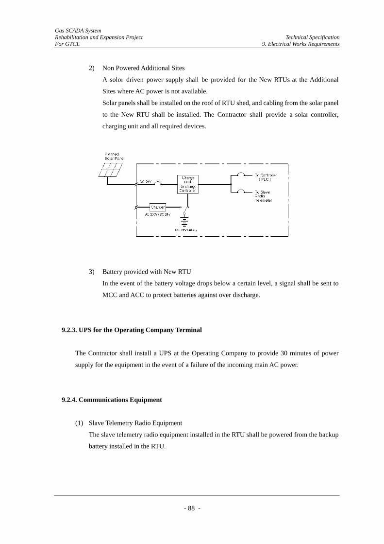
Gas SCADA System Rehabilitation and Expansion Project Technical Specification For GTCL 9. Electrical Works Requirements
- 88 -
2) Non Powered Additional Sites
A solor driven power supply shall be provided for the New RTUs at the Additional
Sites where AC power is not available.
Solar panels shall be installed on the roof of RTU shed, and cabling from the solar panel
to the New RTU shall be installed. The Contractor shall provide a solar controller,
charging unit and all required devices.
3) Battery provided with New RTU
In the event of the battery voltage drops below a certain level, a signal shall be sent to
MCC and ACC to protect batteries against over discharge.
9.2.3. UPS for the Operating Company Terminal
The Contractor shall install a UPS at the Operating Company to provide 30 minutes of power
supply for the equipment in the event of a failure of the incoming main AC power.
9.2.4. Communications Equipment
(1) Slave Telemetry Radio Equipment
The slave telemetry radio equipment installed in the RTU shall be powered from the backup
battery installed in the RTU.
Gas SCADA System Rehabilitation and Expansion Project Technical Specification For GTCL 9. Electrical Works Requirements
- 89 -
(2) Master Telemetry Stations
The Contractor shall provide a backup battery (48V) for the communication equipment
installed in the Master Telemetry Stations. In addition to the above backup battery, an
emergency generator shall be provided at the following Mater Telemetry Stations:
1) Monohordi
2) Eleng
3) Mirasara
4) Feni
5) Laksham
6) Chandpur
The generator shall be of manual start/stop, 3 phase 4 wire, 400/230 V and output capacity of
the generator shall be 15 kVA.
9.3. Technical Specifications
9.3.1. Uninterruptible Power Supply (UPS) for MCC and ACC
(1) General
The UPS shall be manufactured in accordance with IEC 439 and BS 800 or equivalent
standards. The capacity of each UPS shall be designed by the Contractor based on the
proposed equipment’s power consumption.
(2) Components of UPS
The UPS shall comprise the following major components:
1) Battery charger
2) Static inverter
3) Bypass switch
4) Battery
5) Status monitoring panel
(3) Rating
Output
Nominal Output Voltage : AC 230V
Input
Input Voltage : Single Phase AC 230V or 3 Phase 4 wire 400/230 V
Capacity : min. 15kVA
Gas SCADA System Rehabilitation and Expansion Project Technical Specification For GTCL 9. Electrical Works Requirements
- 90 -
(4) Battery Charger
1) The battery charger shall be automatic solid state type, capable of rated output with an
input voltage tolerance of +10% to -l5% and input frequency ±l0%.
2) The battery charger shall be capable of automatic recharge, equalizing and floating
operations to suit the battery type.
(5) Static Inverter
1) The inverter shall be static type, capable of supplying full load, continuously with
overload capability, performance characteristics shown below are for 0 to 100% load at
80% power factor, and for input variations from battery discharged value to charger
maximum output value:
±2% voltage steady rated
±1 Hz frequency when operating on internal frequency
Wave shape: Less than 5% harmonic distortion for all possible operating
conditions.
(6) Bypass Switch
1) A static bypass switch shall provide no-break transfer of AC loads from the inverter to
the alternative supply and back to the inverter, and have performance characteristics
equal to those of the inverter.
2) A manual bypass shall be provided and be mounted in the same cubicle/section as the
static switch to allow manual transfer in the event of maintenance or failure of
equipment.
(7) Batteries
1) Maintenance free sealed lead acid batteries shall be employed and the guaranteed life
of battery shall be a minimum of 10 years.
2) The battery capacity shall be 20% in excess of what is required to achieve the specified
emergency discharge duty.
3) The battery back-up power supply duration is 8 hours for SCADA and Communication
Systems, and 4 hours for building emergency lighting.
Gas SCADA System Rehabilitation and Expansion Project Technical Specification For GTCL 9. Electrical Works Requirements
- 91 -
9.3.2. Backup Battery
(1) General
1) The Contractor shall provide a battery backup for the New RTUs and Master
Telemetry Stations.
2) The backup duration of the batteries for the RTU and Master Telemetry Stations is 24
hours and 48 hours, respectively. The Contractor shall design the capacity (kVA) of the
batteries based on the power consumption of the relevant equipment.
3) The batteries for the RTUs shall be housed in RTUs however the batteries for the
Master Telemetry Stations shall be mounted on a steel rack. The steel rack shall be
painted to resist the corrosive properties of the electrolyte.
4) Batteries and chargers shall be complete with control panels. The battery charger panel
shall incorporate an input switch and an output switch to allow the charger to be
readily isolated for maintenance.
(2) Batteries
1) Maintenance free sealed lead acid batteries shall be used and the guaranteed life of
each battery shall be a minimum of 10 years.
2) The battery capacity shall be 20% in excess of what is required to achieve the specified
emergency discharge duty.
(3) Battery Charger
1) The charger shall be suitable for supplying the initial charging requirements, boost
charging a battery subsequent to an emergency discharge, supplying the maximum DC
load whilst float charging both batteries and providing 20% spare capacity.
2) DC out put shall be suitable for DC 24/48V nominal load voltage with float and boost
charging.
3) A changing over switch for float/boost charging shall be provided.
4) The charger shall be provided with protection devices such as over-voltage and
under-voltage cut relays to protect the equipment against fluctuation in voltage.
9.3.3. Solar Panel with Battery
At sites where no AC 230V power is available, the Contractor shall provide solar power supplies
consisting of solar panels, a charging and discharging controller and batteries. The specifications
for the batteries are referred to in Section 9.3.2.
Gas SCADA System Rehabilitation and Expansion Project Technical Specification For GTCL 9. Electrical Works Requirements
- 92 -
(1) Solar Panels
1) General
Solar panels are to be installed in a very limited space (on the roof of the RTU shed).
The Contractor shall design a solar panel that has the smallest solar panel footprint.
2) The solar panel shall be of a durable construction and designed for use in a tropical
environment.
3) The Contractor shall design the exact number of solar panels required based on the
solar radiation of Bangladesh and required power consumption of the equipment in the
RTU to keep continuous operation of the RTU. Regarding tentative battery capacity,
24 hours as specified, the Contractor shall review the specified capacity based on the
solar panel output and power consumption, and all calculation data shall be submitted
to the Engineer prior to install the equipment.
(2) Charge and Discharge Controller
A charging and discharging controller together with overcharging protection, and a low
voltage disconnector to protect the battery from over discharge shall be provided. This
controller shall be equipped with back-flow (battery to solar panel) prevention device.
The charging and discharging controller shall be provided with an AC 230V input terminal
for boost charge of the battery. The boost charge will be carried out by using a potable type
AC 230 V generator.
9.3.4. UPS for Computers installed at the Operating Company
The Contractor shall provide the UPS for the HMI installed in the Operating Company.
The capacity of the battery shall be calculated by the Contractor based on the electrical demand
of the HMI.
(1) Output
Nominal Output Voltage : AC 230V
Output Voltage Distortion : Less than 5% at full load
Output Frequency : 47 Hz – 53 Hz
(2) Input
Input Voltage : Single Phase AC 230V ±20%
Input Frequency : 50 Hz ± 3 Hz
Serge Protection : to be provided
Gas SCADA System Rehabilitation and Expansion Project Technical Specification For GTCL 9. Electrical Works Requirements
- 93 -
(3) Capacity : min. 30 minutes operation of HMI in the event
failure/outage of the incoming mains supply
(4) Battery : Maintenance free sealed Lead-Acid battery
(5) Unattended shutdown
Provision of an unattended shutdown device for HMI.
A software interface shall provide automatic, unattended shutdown when the battery voltage
drops below a certain level.
9.3.5. Emergency Generator
Frequency : 50 Hz
Out put : 15 kVA
Rated Voltage : 400/230 V, 3 phase 4 wire
Power Factor : 0.8 (lagging)
Voltage Regulation : ±2% of nominal from no-load to full load
Excitation : Brushless, Rotating Exciter (with AVR)
Engine : Diesel engine including all required accessories.
9.3.6. Portable Generator for Maintenance
A portable generator shall be provided for maintenance of the battery for the RTUs located
where AC power is not available.
Frequency : 50Hz
Output : 1kVA
Rated Voltage : 230V single phase
7 sets of generators shall be provided and will be kept at the Master Telemetry Stations
monitoring RTUs without AC power supply.
9.3.7. MCB Box
The Contractor shall provide a MCB Box for feeding AC 230V to the New RTU.
Rated MCB : Molded Case Circuit Breaker 2 pole 50 AF/ 20 AT
Box : The MCB shall be installed in an IP55 enclosure
Gas SCADA System Rehabilitation and Expansion Project Technical Specification For GTCL 9. Electrical Works Requirements
- 94 -
9.3.8. Cables
(1) General
The cables shall be made of flame retardant cable and shall have stranded copper
conductors with minimum cross section area shall be as follows:
1) Power Cable : 2.5 mm2
2) Control Cable : 1.5 mm2
(2) Power Cable/Control Cable
0.6/1kV XLPE/PVC/SWA/PVC flame retardant cable
Conductor : copper
Insulation : XLPE
Armour : Galvanized steel wire
Outer Sheath : Blue colored PVC, compound having flame retardant properties
as per IEC 60332-3 Category A
Cable Identification : 3 cores Red, Yellow, Blue
(3) Control Cables (Screened Pair Cable)
0.6/1kV XLPE/PE/SWA/PVC-SLA, overall screened flame retardant cable (control cable)
Conductor : copper
Insulation : XLPE
Screen : Laminated aluminum polyester tape with tinned copper drain
wire of 0.5 mm2
Armour : Galvanized steel wire
Outer Sheath : Blue colored PVC, compound having flame retardant properties
as per IEC 60332-3 Category A
Cable Identification : 1 pair - Red, Black
(4) Control Cables (Multi Screened Pair Cable)
0.6/1kV XLPE/PVC/PSLA/PE/SWA/PVC (control cable), individual pair screened flame
retardant cable
Conductor : copper
Insulation : XLPE
Screen : Laminated aluminum polyester tape with tinned copper drain
wire of 0.5mm2
Armour : Galvanized steel wire
Outer Sheath : Blue colored PVC, compound having flame retardant properties
Gas SCADA System Rehabilitation and Expansion Project Technical Specification For GTCL 9. Electrical Works Requirements
- 95 -
as per IEC 60332-3 Category A
Cable Identification : Manufacturer’s standard
9.3.9. Cable Laying and Cable support
(1) Cables laid directly in the ground shall have the following depth of cover:
Power cable :500 mm
Control cable : 500 mm
Cable markers shall be provided to indicate where cables have been laid.
(2) Cable Tray
1) All tray work and accessories shall be heavy duty and sized to provide 25% additional
free space.
2) The minimum clearance behind the tray shall be sufficient to allow for fixing of cables,
which shall relate to tray width, but shall not be less than 25 mm.
3) The galvanized cable tray shall be perforated, heavy-duty return flange type, hot dipped
galvanized after manufacturing. All cut ends shall be made good to equal protection as
uncut lengths, using "galvanized" paints.
4) The plastic coated cable tray shall be diamond pattern, and covered with heavy duty,
black PVC. It shall only be used where, for reasons of corrosion, galvanized tray work
is impracticable.
5) The rigid PVC cable tray shall be manufactured from rigid un-plasticized PVC having a
thickness of not less than 3 mm. It shall be perforated and have provision for a cover.
The manufacturing material shall be self extinguishing or non flammable and suitable
for use in ambient temperatures of 0℃ to +80℃.
(3) Conduit
1) The steel conduit shall be heavy duty, welded, screwed and galvanized to Class 4 of the
relevant British Standard.
2) They shall be sized to enable satisfactory accommodation of the cables required for the
contract with a further 25% free space for future installations.
3) Conduit systems shall be completely installed before commencing cable installations.
4) They shall be securely fixed by means of distance saddles to give not less than 6 mm
clearance between the conduit and the building.
Gas SCADA System Rehabilitation and Expansion Project Technical Specification For GTCL 9. Electrical Works Requirements
- 96 -
9.3.10. Lightning Protection
A one-meter long lightning rod complete with a down conductor and earthing system shall be
provided. The earthing resistance for the lightning protection shall be less than 10 obm.
The lightning rod shall be installed at the top of the antenna mast.
9.3.11. Earthing
(1) All new power cables from the existing distribution board to the MCB Box and the MCB
Box to the New RTU shall be of 3 cores; Live, Neutral and Earth. The earth core shall be
terminated at the SCADA earth star point.
(2) All equipment enclosures to which an electrical power supply is connected shall have a main
earth connection point suitable for a l0 mm2 wire. The exposed metal cases of all electrical
apparatus shall be connected to the SCADA star point earth unless the apparatus is nearer to
the system earth point, in which case the connection shall be to the system earth point. The
protective and non-live metalwork of the panel shall have a maximum resistance not
exceeding l0 milliohms to the SCADA earth star point. An earth cable shall then be taken
from the SCADA star point earth to the system earth point within the building containing the
SCADA equipment. The maximum resistance between the SCADA star point earth and the
system earth shall not exceed l0 milliohms.
(3) All equipment to be earthed shall be connected to the SCADA earth star point using
green/yellow PVC insulated cable of the appropriate size.
(4) The steel wire armoured power cable shall not be used as the earthing conductor.
(5) Equipment shall not be earthed to its chassis but shall have the earth points brought to an
insulated point from which the connection to a special logic earth can be made.
(6) Provision shall be made for the termination of signal screens, or to maintain the continuity of
isolated screens as required.
(7) The minimum earthing conductor shall be 2.5 mm2.

Gas SCADA System Rehabilitation and Expansion Project Technical Specification For GTCL 9. Electrical Works Requirements
- 97 -
9.3.12. Cable Terminals
(1) A steel wire armoured (SWA) cable shall be terminated by using a cable gland. The cable
gland shall be suitable for the environment in which they are to be used, and shall be complete
with PVC shrouds, back nuts and bonded earth tags.
(2) AC/DC power cables shall be terminated in a screw clamp/clamp terminal.
(3) Instrument cable cores and internal connection cores shall be terminated with polyamide
type terminals, having socket screw clamp connections with a knife-edge switch
disconnection.
Gas SCADA System Rehabilitation and Expansion Project Technical Specification For GTCL 10. Civil Works Requirements
- 98 -
10. Civil Works Requirements
10.1. General Information
10.1.1. Introduction
(1) This part provides a general description of the civil works required for the Project.
10.1.2. Scope of Work
(1) The Contractor shall carry out pre-installation civil works to provide foundations or to
prepare sites and buildings for the installation of the New System.
(2) The Contractor shall remove and dispose of unnecessary existing equipment for the
installation of the New System.
(3) The Contractor shall design and construct foundations and sunshades for new RTUs at
Additional Sites.
(4) The Contractor shall refurbish existing foundations and sunshades for the replacement of
existing RTUs at Original Sites, if necessary.
(5) The Contractor shall design and construct the instrument stands with foundations and
sunshades at sites where new instruments are installed.
(6) The Contractor shall refurbish existing instrument stands with foundations and sunshades, if
necessary, for the continuous use of existing instruments.
(7) The Contractor shall refurbish existing equipment rooms to accommodate new SCADA and
Communication equipment according to the requirement.
(8) The Contractor shall carry out soil investigation if it is required for the design of foundations
mentioned above.
(9) The Contractor shall provide temporary facilities required for the execution of the works
described herein.
Gas SCADA System Rehabilitation and Expansion Project Technical Specification For GTCL 10. Civil Works Requirements
- 99 -
(10) All other works as described and/or implied in the Tender Documents to complete the
Contract.
10.1.3. General Requirements
(1) All designs and constructions shall be prepared and carried out in accordance with British
Standards and codes of practice or other equal national standards approved by the Engineer.
Any departure from these standards and codes shall be subject to approval by the Engineer.
(2) All works shall be carried out in accordance with recognized standards of safety. The
Engineer shall have the power to instruct the Contractor to comply with the safety
requirements. This shall not relieve the Contractor of any of his obligations under the
Contract.
(3) All design documents shall indicate the referred standard and codes of practice, and the
Contractor shall be able to present the copies of the referred standard and codes of practice at
the request of the Engineer.
(4) Foundations shall be designed to suit the ground conditions.
(5) The Contractor shall be responsible for the complete design and design check of the Works
which shall be submitted to the Engineer for approval.
(6) The Contractor shall ensure that the submitted design is adequate in all respects for proper
functioning of the System.
(7) The Contractor shall submit the Method Statement for the works that describes the method &
sequence of the construction, working program, quality assurance, referred standards and
codes of practice, etc. for the approval of the Engineer.
(8) For any deviation from the approved specification and quality, the Engineer will have the
authority to instruct the Contractor to reinstate such work to the required standard.
(9) The Contractor shall arrange suitably qualified competent civil engineers on site to supervise
the work and ensure the quality and progress of the civil works is achieved and maintained.

Gas SCADA System Rehabilitation and Expansion Project Technical Specification For GTCL 10. Civil Works Requirements
- 100 -
The site engineers shall be responsible for liaising with the Engineer.
(10) The Contractor's engineers shall inspect and test the works to ensure that all works are done
as per approved design, standard and specification, and shall submit the records of such
inspections and tests to the Engineer for approval.
(11) The Contractor shall carry out all geotechnical investigations necessary and submit the
reports to the Engineer for approval. The Contractor shall use the approved Geotechnical
Reports for designing all foundations.
(12) The Contractor shall also ensure that progress is maintained in accordance with the
contracted program of work.
(13) The Contractor shall coordinate with operating companies of existing gas facilities where
Contractor’s works shall be carried out, and ensure no disturbance to the operations of
existing gas facilities, and also ensure no damage to the existing gas facilities.
10.2. Foundations & Sunshades for Equipment
10.2.1. General
(1) New stands, foundations and sunshades shall be designed and constructed for the installation
of new RTUs and instrument for the Project at Additional and Original Sites.
(2) Existing stands, foundations and sunshades shall be refurbished at Original Sites, if
necessary.
(3) A typical indicative plan and elevation for new stand, foundation and sunshade are shown in
Figure 10.1.
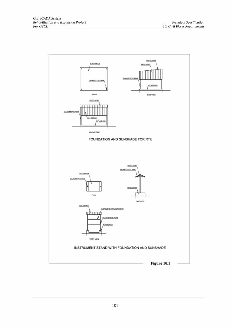
Gas SCADA System Rehabilitation and Expansion Project Technical Specification For GTCL 10. Civil Works Requirements
- 101 -

Gas SCADA System Rehabilitation and Expansion Project Technical Specification For GTCL 10. Civil Works Requirements
- 102 -
10.2.2. Requirements
(1) The Contractor shall design and construct reinforced concrete foundation with sunshade for
New RTU at Additional Sites.
(2) The Contractor shall remove and dispose the existing RTU, and refurbish the existing
foundation and sunshade of existing RTU, if necessary, in order to install New RTU at
Original Sites.
(3) The Contractor shall design and construct new Instrument Stand with reinforced concrete
foundations and sunshades for new instruments installation at Original and Additional Sites.
(4) The Contractor shall refurbish the existing Instrument Stand with foundation and sunshade
for the existing instrument(s), if necessary for the continuous use of the existing
instrument(s).
(5) The new foundation shall be designed to suit ground conditions and to resist possible loads
on the structure.
(6) New sunshades shall be designed to adequately house the RTUs and instruments to provide
ample protection against sunlight and rain.
(7) Ducts for cables shall be properly embedded into reinforced concrete foundations.
(8) At remote sites without commercial power supply, new sunshades for RTUs shall be
designed to support solar power panels on the roof.
10.3. Refurbishment of Radio Rooms/Buildings
10.3.1. General
(1) There are a total of 20 existing radio rooms/buildings at Master Telemetry Stations to be
refurbished for the installation of new communication equipment collecting natural gas
process data from RTUs and sending it to Control Centers through BTCL’s leased network.

Gas SCADA System Rehabilitation and Expansion Project Technical Specification For GTCL 10. Civil Works Requirements
- 103 -
(2) The existing radio rooms/buildings are listed in Table 10.1. with further details.
Radio Room Battery Room Entire Building
306 10-HOR-300M Horipur Head Office This is GTCL's radio building entirelydedicated to the telecommunication system forthe exsiting SCADA system.Entire building shall be refurbished toaccommodate new equipment.
4.1m x 3.5m 3.1m x 2.9m 10.6m x 4.6m
405 10-KAI-400M Kailashtilla2 Radio Ditto Ditto Ditto Ditto
608 10-JAL-600M Jalalabad Head Office Radio equipment is installed at penthouse ofthe commercial building at Sylhet city.Since this building is not owned by GTCL,refurbishment is not necessary and onlycleaning is required.
Not Applicablebut cleaning is
required
Not Applicablebut cleaning is
required
Not Applicable
604 10-FCH-600M Fenchugonj Radio This is GTCL's radio building entirelydedicated to the telecommunication system forthe exsiting SCADA system.Entire building shall be refurbished toaccommodate new equipment.
4.1m x 3.5m 3.1m x 2.9m 10.6m x 4.6m
302 10-RAS-300M Rashidpur Gas Field Ditto Ditto Ditto Ditto
203 10-HOB-200M Hobigonj Gas Field Ditto Ditto Ditto Ditto
400 10-ASH-400M Ashuganj New Radio Ditto Ditto Ditto 8.5m x 4.6m
120A 20-BKB-100M Bakhrabad New Radio Ditto 4.1m x 3.5m 3.0m x 2.9m 10.6m x 4.6m
114 20-CML-100M Comilla Head Office Ditto 4.3m x 3.0m 2.9m x 2.5m 9.6m x 6.7m
115 20-LAK-100M Laksham Radio Ditto 4.2m x 3.0m 2.8m x 2.3m 12.7m x 5.0m
116 20-CHA-100M Chandpur Ditto 3.0m x 2.8m 3.0m x 1.5m 9.0m x 3.0m
102 20-FEN-100M Feni Ditto 4.2m x 3.0m 2.9m x 2.5m 6.6m x6.3m
118 20-MIR-100M Mirasarai Ditto 3.0m x 3.0m 3.1m x 1.8m 10.7m x 4.7m
105 20-FAU-100M Faujdarhat Ditto 3.5m x 2.4m 3.0m x 2.0m 7.8m x 4.1m
109 30-DMR-100M Demra Ditto 3.0m x 2.7m 3.5m x 2.8m 5.0m x 4.9m
702 30-PBG-700M Petrobangla Head Office Radio equipment is installed in the roomlocated at 9F of the commercial building inDhaka city.Since this building is not owned by GTCL,refurbishment is not necessary and onlycleaning is required.
Not Applicablebut cleaning is
required
Not Applicablebut cleaning is
required
Not Applicable
510 40-MHD-500M Monohordi A part of GTCL's office building is currentlyused for the telecommunication system of theexisting SCADA system.Cleaning and refurbishment are required onlyfor the rooms used for the telecommunicationsystem and no refurbishment is required atother part of the building.
6.3m x 3.9m 3.3m x 3.0m Not Applicable
508 40-ELE-500M Elenga Ditto 3.6m x 3.2m 1.7m x 1.5m Not Applicable
- 40-MYM-500M TITAS Mymensing Office A part of TGTDCL's office building is currentlyused for the telecommunication system of theexisting SCADA system.Cleaning and refurbishment are required onlyfor the rooms used for the telecommunicationsystem and no refurbishment is required atother part of the building.
6.5m x 2.7m 3.0m x 2.0m Not Applicable
511 40-TRK-500M Tarakandi Ditto 4.7m x 4.0m 3.2m x 2.0m Not Applicable
Table 10.1. Radio Rooms and Buildings at Master Telemetry Stations
Master StationOldSite
Code
Approximate Size of Rooms/Buildingsfor RefurbishmentState of the Radio Rooms/Buildings
NewSite
Code
Gas SCADA System Rehabilitation and Expansion Project Technical Specification For GTCL 10. Civil Works Requirements
- 104 -
10.3.2. Requirements
(1) The Contractor shall remove and dispose of the existing radio equipment that is no longer
required for the new Communication System.
(2) The Contractor shall examine the condition of the existing radio room and repair defects if
they are found.
(3) The Contractor shall clean and neatly touch-up the external and internal finish of existing
radio rooms/buildings to accommodate new radio equipment.
10.4. Refurbishment of Control Centers
10.4.1. General
(1) There are two existing Control Centers for the Existing System. One is the Main Control
Center located at Demra and the other is the Auxiliary Control Center located at Ashuganj.
Existing equipment of these control centers shall be replaced with new equipment. Therefore
the existing equipped rooms shall be refurbished for the installation of new equipment after
the removal of existing equipment.
10.4.2. Requirements
(1) The Contractor shall remove and dispose of existing SCADA equipment that is no longer
required for the new SCADA System.
(2) The Contractor shall examine the present condition of the following existing rooms at both
Control Centers and repair defects if they are found.
System Management Room
Equipment Room
Battery Room
(3) The Contractor shall clean and neatly touch-up the internal finishes of these rooms at both
Control Centers to accommodate the new SCADA equipment.
Gas SCADA System Rehabilitation and Expansion Project Technical Specification For GTCL 11. Inspection and Testing
- 105 -
11. Inspection and Testing
11.1. General
At stages throughout the Contract, formal tests shall be carried out and all test result shall be
submitted by the Contractor. These test procedures shall be designed to show that the System
meets the requirements of the Specifications, and shall be completed to the satisfaction of the
Engineer before subsequent stages can proceed.
The procedures shall define detailed test method and procedures, measuring items, testing
equipment to be used and recording forms for test results, and shall contain design values and
tolerances which will be treated as the criteria for evaluation of each test. The test procedure shall
be submitted to the Engineer for approval prior to respective test.
The Factory Acceptance Test (FAT), Site Acceptance Test (SAT), Commissioning Test and the
Final System Test to be carried out by the Contractor shall include but are not limited to the
following:
Visual check
Name plate check
Dimensional check
Cabling, wiring, and grounding check
Protective and safety system function check
Functional test
Operation test
Performance test
11.2. Test Equipment and Facilities
(1) The Contractor shall provide for the purpose of the tests all equipment and services required
for testing, including but not limited to:
1) Laboratory test instruments
2) Special test equipment, simulators and test software
3) Other items of equipment and software specified elsewhere as part of the Contractor's
supply, or required for the purpose of conducting a test
4) Consumables

Gas SCADA System Rehabilitation and Expansion Project Technical Specification For GTCL 11. Inspection and Testing
- 106 -
5) Payment of all communications charges during the Factory Acceptance Test including
local and international telephone calls.
(2) All test instruments shall be subject to routine inspection testing and calibration, by the
Contractor. All test instruments shall be subject to approval by the Engineer, and if required
by the Engineer shall be calibrated at the expense of the Contractor by an approved standards
laboratory.
11.3. Test
The following tests shall be carried out by the Contractor
(1) Factory Acceptance Test (FAT)
(2) Site Acceptance Test (SAT)
(3) Commissioning Test
(4) Final System Test
11.3.1. Factory Acceptance Test (FAT)
Before any item of the equipment is packed or delivered from the manufacturer's factory, all tests
itemized in the relevant sections of these Technical Specifications shall be carried out by the
Contractor as far as practicable to prove compliance with the requirements of the Specifications.
All parts of the SCADA and Telecommunication System shall be assembled in the manufacturer’s
factories prior to shipment and tests shall be performed by the Contractor as may be required to
demonstrate the adequacy of the systems and its component parts. All tests should simulate
normal operating conditions as closely as possible.
The Contractor shall give the call regarding FAT well in advance with a minimum of 30 days
notice of the date at which the system is ready for testing.
11.3.2. Site Acceptance Test (SAT)
After the equipment has been fully assembled/installed, the Contractor shall carry out the Site
Acceptance Test.
(1) The SAT shall be carried out on all equipment and software supplied under the Contract.
(2) The SAT shall be carried out after the equipment has been installed at the site.
Gas SCADA System Rehabilitation and Expansion Project Technical Specification For GTCL 11. Inspection and Testing
- 107 -
(3) The SAT shall be performed with equipment at the locations in which they will eventually
operate, or in a typical location in the case of portable equipment.
(4) The SAT shall demonstrate that the overall design of the System meets the requirements of
the Specification in the field, using the actual communications network, including equipment
supplied by others.
(5) The installation shall be inspected to ensure compliance with the installation manual and
cable drawings and to verify satisfactory condition of all equipment.
11.3.3. Commissioning Test
The Commissioning Tests shall be performed following completion of the installation of
equipment at each site. The Commissioning Test shall be carried out under the conditions of
connecting all the equipment.
(1) The Contractor shall carry out the Commissioning Tests in the presence of the Employer’s
Personnel and the Engineer to demonstrate that all guarantees and technical particulars as
listed in the Contract Documents are satisfied and that all the equipment is properly installed.
(2) The Commissioning Test shall be conducted on all equipment and software supplied under
the Contract in accordance with the SAT document approved by the Employer.
(3) The Commissioning Test shall establish all aspects of functionality, including proving of all
types of communication link.
(4) The Commissioning Test shall include both polling of the RTU by the SCADA Server and
generating an alarm in the RTU to ascertain it can initiate a call to the Server. The necessary
test software/configuration to perform the above shall be supplied by the Contractor
11.3.4. Final System Test
The Final System Test shall be carried out to confirm continuous functional operation of the
systems with the required system reliability and availability. This test aims at keeping the
complete integrated system operating for 24 hours a day for a period of 14 days.
In case of failure, the tests shall be restarted till the system operates without failure of any
system functionality for 14 days.
The Final System Test shall be carried out in accordance with a test plan and procedures approved
by the Employer.
The test result obtained during the Final System Test shall be documented in the form of report and
submitted to the Employer for approval.
Gas SCADA System Rehabilitation and Expansion Project Technical Specification For GTCL 12. Operation and Maintenance Support and Spare
- 108 -
12. Operation and Maintenance Support and Spare
12.1. Introduction
The New System is required to provide full operational facilities for a minimum of fifteen (15) years.
The Contractor shall ensure that supplier is able to provide spares for 15 years.
12.2. Operation Support
12.2.1. General
In addition to or as part of the staff required for maintenance support and training, the Contractor
shall provide two engineers in Bangladesh for the 24 months period from System Take-over to
Contract Completion. The two engineers shall be a SCADA engineer and a communication
engineer
The engineers shall be based between Demra MCC, Ashuganj ACC and GTCL Head Office. In
addition they will be required to travel to all sites covered by the Contract as and when required.
The engineers shall work under the direction of the Engineer and/or as directed by the Employer.
Each engineer shall work a minimum of 42 working weeks per year in Bangladesh. At all times at
least one engineer shall be working in Bangladesh.
12.2.2. Qualifications and Experience
The said two engineers shall be degree qualified with a minimum of five years practical
experience in the relevant area.
The SCADA engineer shall have experience in SCADA systems configuration and maintenance,
and shall advise and assist the Employer in configuring and maintaining the System.
The Communication engineer shall have experience in communication systems configuration and
maintenance, and shall advise and assist the Employer in configuring and maintaining the System.
12.3. Maintenance Philosophy
The Contractor shall provide all maintenance services for the System during the two years warranty
period following System Taking-Over.
Gas SCADA System Rehabilitation and Expansion Project Technical Specification For GTCL 12. Operation and Maintenance Support and Spare
- 109 -
On completion of the warranty period, the Employer will enter maintenance contracts for all
maintenance activities for the System and the provision of spare parts.
The Contractor shall support these maintenance contracts through the vendor and/or relevant
maintenance service provider for the following services:
(1) Routine maintenance
(2) First level hardware maintenance
(3) Repair of all items replaced under first level maintenance
(4) Emergency call-out
(5) Software maintenance
First level maintenance and support shall include identification of faults down to module or card
level and on-line replacement of faulty equipment.
Notwithstanding this requirement to maintain the System, the Contractor shall provide
documentation and training of the Employer's staff during the Contract period, to a level that would
allow first level and routine maintenance to be performed.
12.4. Design to Facilitate Maintenance
The System shall have remote and local diagnostic facilities to allow for identification of faults
necessary for first level maintenance.
Equipment shall be designed to allow the on-line replacement of modules or cards without affecting
System operation.
Peripheral equipment shall be easily removable from service and either replaced by standby
equipment or spare equipment without affecting System operation.
12.5. Spare Parts
During the two years warranty period, the Contractor shall provide all spare parts and consumables
required for the support of the System appropriate to maintaining the System within the specified
availability. These spare parts shall be stored on the Employer's premises, and at the end of the
Contract period all spare parts that have been used shall be replaced.
All spare parts shall be identical, electrically and mechanically, to the corresponding parts in the
equipment provided and shall be suitably packed and clearly marked, ready for storage.
Spare or replacement parts shall be fully compatible with and necessarily similar to items previously

Gas SCADA System Rehabilitation and Expansion Project Technical Specification For GTCL 12. Operation and Maintenance Support and Spare
- 110 -
supplied.
The Contractor shall furnish full contact address of all the equipment suppliers with their
(supplier’s) commitment letter to support spares provision to the Employer, the local associate or
any other party undertaking maintenance contracts with the Employer to maintain the System
availability for its lifetime.
The suppliers shall maintain the availability of spares or replacement parts for the System lifetime.
If the supplier intends to discontinue the manufacture of spare or replacement parts for the works
during the maintenance Contract with the Employer, the supplier shall supply such spare or
replacement parts required to maintain the System availability for the remainder of the maintenance
Contract to the local associate. This shall include any repair service that may be discontinued.
If the supplier intends to discontinue the manufacture of spare or replacement parts for the works, the
supplier shall either:
(1) Forthwith give notice to the Employer of such intention and afford the Employer the
opportunity of ordering all spare or replacement parts required to maintain the System
availability for its lifetime.
(2) Or sell to the Employer such drawings, patterns, specifications and other information as he may
have in his possession to enable him to make or have made such spares or replacement parts.
12.6. Maintenance Contracts
12.6.1. General
The maintenance Contractor shall provide maintenance contracts for all System hardware and
software.
Hardware maintenance contracts shall conform to the Model Form of Conditions of Contract for
the Servicing (Maintenance) of Computer Equipment of The Institute of Purchasing and Supply,
1988. The Contract shall provide for both preventive and remedial maintenance to a specified
standard of service.
Software maintenance contracts shall be to the Model Form of License Agreement for the use of
Computer Software Products of the Institute of Purchasing and Supply, IPS Model L 1987, The
Contract shall provide remedial maintenance to a specified standard of service.
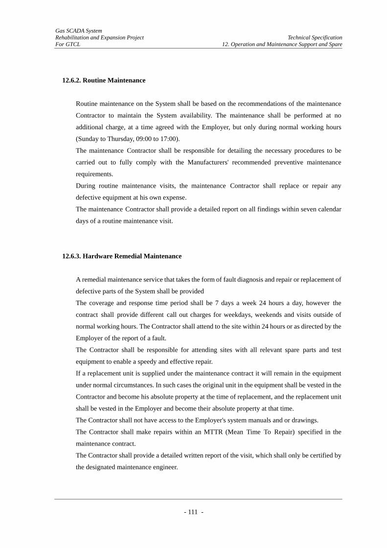
Gas SCADA System Rehabilitation and Expansion Project Technical Specification For GTCL 12. Operation and Maintenance Support and Spare
- 111 -
12.6.2. Routine Maintenance
Routine maintenance on the System shall be based on the recommendations of the maintenance
Contractor to maintain the System availability. The maintenance shall be performed at no
additional charge, at a time agreed with the Employer, but only during normal working hours
(Sunday to Thursday, 09:00 to 17:00).
The maintenance Contractor shall be responsible for detailing the necessary procedures to be
carried out to fully comply with the Manufacturers' recommended preventive maintenance
requirements.
During routine maintenance visits, the maintenance Contractor shall replace or repair any
defective equipment at his own expense.
The maintenance Contractor shall provide a detailed report on all findings within seven calendar
days of a routine maintenance visit.
12.6.3. Hardware Remedial Maintenance
A remedial maintenance service that takes the form of fault diagnosis and repair or replacement of
defective parts of the System shall be provided
The coverage and response time period shall be 7 days a week 24 hours a day, however the
contract shall provide different call out charges for weekdays, weekends and visits outside of
normal working hours. The Contractor shall attend to the site within 24 hours or as directed by the
Employer of the report of a fault.
The Contractor shall be responsible for attending sites with all relevant spare parts and test
equipment to enable a speedy and effective repair.
If a replacement unit is supplied under the maintenance contract it will remain in the equipment
under normal circumstances. In such cases the original unit in the equipment shall be vested in the
Contractor and become his absolute property at the time of replacement, and the replacement unit
shall be vested in the Employer and become their absolute property at that time.
The Contractor shall not have access to the Employer's system manuals and or drawings.
The Contractor shall make repairs within an MTTR (Mean Time To Repair) specified in the
maintenance contract.
The Contractor shall provide a detailed written report of the visit, which shall only be certified by
the designated maintenance engineer.

Gas SCADA System Rehabilitation and Expansion Project Technical Specification For GTCL 12. Operation and Maintenance Support and Spare
- 112 -
12.6.4. Software Remedial Maintenance
A software remedial maintenance service that takes the form of fault diagnosis and correction of
software shall be provided.
The coverage and response time period shall be 7 days a week 24 hours a day however the contract
shall provide different call out charges for weekdays, weekends and visits outside of normal
working hours. The Contractor shall attend to site within 24 hours of the report of a fault.
The Contractor shall be responsible for attending sites with all relevant equipment to enable a
speedy and effective repair.
The Contractor shall not have access to the Employer's system manuals and or drawings.
The Contractor shall make repairs within an MTTR specified in the maintenance contract.
The Contractor shall provide a detailed written report of the visit, which shall only be certified by
the designated maintenance engineer.
In the case of non-critical software errors or faults, the Employer will agree with the Contractor on
a mutually convenient time for the Contractor to attend the site and be granted access to the
System.
All successful Software Remedial Maintenance will be documented and included on all system
working and back-up copies of the software.
12.6.5. Consumables
The Contractor shall offer to provide all consumables such as printer paper, floppy disks, printer
ribbons, plotter pens, streamer tapes etc., as with spare parts.
Gas SCADA System Rehabilitation and Expansion Project Technical Specification For GTCL 13. Training
- 113 -
13. Training
13.1. Introduction
The Contractor shall provide a program of training courses and training to enable the installation,
operation, management and maintenance of the System to be effectively carried out.
13.2. General Course Requirements
Courses shall consist of lectures, discussions, demonstrations and experience of the equipment
involved. Courses shall be prepared in advance and printed sets of course notes shall be provided to
all attendees.
All courses shall be held in English and all course notes shall be written in English.
All equipment to be used for training shall be provided by the Contractor, and its use shall not
interfere with any other use of the System, or with the program or time schedules for commissioning
or testing.
The training staff of the Contractor shall have experience in giving training. The Contractor shall
provide evidence of the training experience and appropriate accreditation of proposed staff six weeks
prior to the start of the first course.
The program of training courses shall be arranged to comply with the program for implementation of
the System and by arrangement with the Engineer.
Courses shall provide attendees with sufficient skills to achieve a level of in-house support required
for the successful operation of the System.
13.3. Categories of Personnel Requiring Training
13.3.1. General
Training shall be provided making due provision for the abilities and needs of the attendees. To
this end the following categories of user should be noted by the Contractor.
13.3.2. Managers
This group of personnel are those charged with responsibility for the safe and efficient running of
Gas SCADA System Rehabilitation and Expansion Project Technical Specification For GTCL 13. Training
- 114 -
the plant. Knowledge on the System operation is needed to enable appreciation of the benefits and
limits of the information available and assist the decision making process. Their involvement is
essentially at an executive level.
13.3.3. Engineers
Engineers will require detailed knowledge of the supplied System to ensure that it becomes a
sustainable and supportable system.
Training in both software and hardware shall be given to cover both the maintenance function and
to deliver the capability for effecting future enhancements.
13.3.4. Operators
Operators have knowledge of gas transmission operations and use of the System as their main
operational tool based at a control centre.
Their responsibility is continuous supervision of the National Gas Grid in a safe and efficient
manner and typical duties include:
(1) Reporting the performance of the pipeline operations, for example how much gas is available,
and from where.
(2) Monitoring maintenance operations, e.g. on valves.
(3) Carrying out appropriate actions when alarms are activated.
13.3.5. Technicians
Technicians perform maintenance and modification duties under the direction of an engineer.
Training should be given in all aspects of system support including planned maintenance and
minor configuration changes.
13.3.6 Trainers
In order to ensure effective in service training and to ensure sustainability of training after the
Contractor's warranty period is over, staff will be identified who in addition to other duties will be
designated as trainers and undergo a 'Training to the Trainers' program. These trainers will then be

Gas SCADA System Rehabilitation and Expansion Project Technical Specification For GTCL 13. Training
- 115 -
assigned to provide in-service training to new staff.
13.4. Training Requirements
13.4.1. Location and Methodology
The Contractor shall provide training in suitable premises at locations of their choice. It is
envisaged that the majority of the training will take place within Bangladesh.
The Contractor shall provide all accommodation, travel costs and subsistence for the Employer's
staff, except for Dhaka based training where only travel and subsistence costs shall be provided.
The Contractor shall maintain records of topics covered, records of who has carried out training
and who has attended.
13.4.2. Training Course during Installation and Commissioning
The Contractor shall provide technology transfer training course to demonstrate and lecture the
installation and commissioning of equipment at site for three months.
13.4.3. Training Course Structure for Operation & Maintenance
The Contractor shall provide technology transfer training where ten members of the Employer's
staff visit an overseas gas transmission company with an established SCADA system in use. The
visit shall consist of seminars, site visit and time spent within control rooms viewing operations.
The course shall demonstrate the benefits and problems encountered when operating a complex
gas transmission grid. The period of the visit shall be four weeks.
The following course structure and guidelines are provided as typical examples of the content and
duration required and the attendees experience. The list shall not be deemed comprehensive and
the Contractor shall devise courses that are appropriate to the System provided and the scope
required.
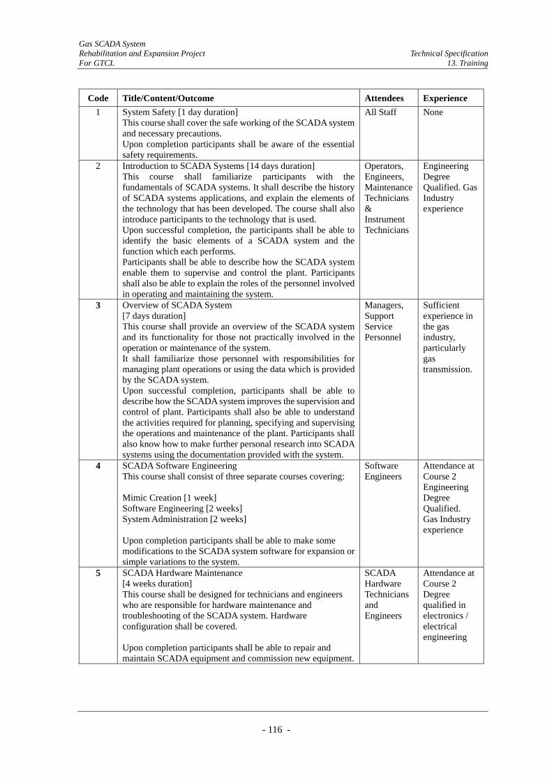
Gas SCADA System Rehabilitation and Expansion Project Technical Specification For GTCL 13. Training
- 116 -
Code Title/Content/Outcome Attendees Experience 1 System Safety [1 day duration]
This course shall cover the safe working of the SCADA system and necessary precautions. Upon completion participants shall be aware of the essential safety requirements.
All Staff None
2 Introduction to SCADA Systems [14 days duration] This course shall familiarize participants with the fundamentals of SCADA systems. It shall describe the history of SCADA systems applications, and explain the elements of the technology that has been developed. The course shall also introduce participants to the technology that is used. Upon successful completion, the participants shall be able to identify the basic elements of a SCADA system and the function which each performs. Participants shall be able to describe how the SCADA system enable them to supervise and control the plant. Participants shall also be able to explain the roles of the personnel involved in operating and maintaining the system.
Operators, Engineers, Maintenance Technicians & Instrument Technicians
Engineering Degree Qualified. Gas Industry experience
3 Overview of SCADA System [7 days duration] This course shall provide an overview of the SCADA system and its functionality for those not practically involved in the operation or maintenance of the system. It shall familiarize those personnel with responsibilities for managing plant operations or using the data which is provided by the SCADA system. Upon successful completion, participants shall be able to describe how the SCADA system improves the supervision and control of plant. Participants shall also be able to understand the activities required for planning, specifying and supervising the operations and maintenance of the plant. Participants shall also know how to make further personal research into SCADA systems using the documentation provided with the system.
Managers, Support Service Personnel
Sufficient experience in the gas industry, particularly gas transmission.
4 SCADA Software Engineering This course shall consist of three separate courses covering: Mimic Creation [1 week] Software Engineering [2 weeks] System Administration [2 weeks] Upon completion participants shall be able to make some modifications to the SCADA system software for expansion or simple variations to the system.
Software Engineers
Attendance at Course 2 Engineering Degree Qualified. Gas Industry experience
5 SCADA Hardware Maintenance [4 weeks duration] This course shall be designed for technicians and engineers who are responsible for hardware maintenance and troubleshooting of the SCADA system. Hardware configuration shall be covered. Upon completion participants shall be able to repair and maintain SCADA equipment and commission new equipment.
SCADA Hardware Technicians and Engineers
Attendance at Course 2 Degree qualified in electronics / electrical engineering

Gas SCADA System Rehabilitation and Expansion Project Technical Specification For GTCL 13. Training
- 117 -
6 Instrument Technicians Course [4 weeks duration] This course shall be designed to familiarize technicians with equipment such as energy metering, gas analysis and intrinsic safety devices. Upon completion technicians shall be able to carry out calibration and simple maintenance operations.
Instrument Technicians
Attendance at Course 2 Electrical Engineering Diploma
7 Material control - Handling [1 week duration] This course shall cover the essential materials control and handling activities such as inventory control, safe handling and custody of materials. Handling of equipment and stock keeping. Upon completion participants could be given control of area store.
Store keepers
Experience in store keeping and security
8 Communications Software Engineering [4 weeks duration] This course shall cover configuration, diagnostics and performance monitoring. Upon completion participants shall be able to make some modifications to the communications systems software for expansion or simple variations to the system.
Comms Engineers
Degree qualified in comms related subjects
9 Communications Hardware Maintenance [4 weeks duration] This course shall be designed for technicians and engineers who are responsible for hardware maintenance and troubleshooting of communications systems. Hardware configuration shall be covered. Upon completion participants shall be able to repair and maintain communications equipment and commission new equipment.
Comms Hardware Technicians and Engineers
Degree qualified in comms related subjects
10 Basic Quality Control & Management [2 weeks duration] This course shall cover the basic elements of calibration, preparation of work instructions and basic auditing techniques.Upon completion participants shall carry out basic quality audits, manage the calibration process and prepare simple work instructions.
Inspectors Experience gained within the gas sector at the supervisor level.
11 Leak Detection [2 weeks duration] This course shall cover the Leak Detection application software. Upon completion of the course participants shall be able to use the application software and the SCADA system in general to monitor for leak detection and to implement operational procedures for dealing with the leak.
Operators Attendance in course 2. Engineering Degree Qualified. Gas industry experience.
12 Load Balancing and System Scheduling [2 weeks duration] This course shall cover the Load Balancing and System Scheduling application software provided with particular emphasis on the Employer's existing operational and organizational involvement in this area. Upon completion the participants shall be able to use the application software to implement load balancing and system scheduling.
Operators Supervisors & Managers
Attendance in course 2. Engineering Degree Qualified. Gas industry experience.

Gas SCADA System Rehabilitation and Expansion Project Technical Specification For GTCL 13. Training
- 118 -
13 Training the trainers [2 weeks duration] This course shall cover basic training skills necessary for providing on the job training. Upon completion the participants shall be able to train new and existing staff in the main tasks for their area of work.
Supervisors & Managers
Attendance in course 2 Extensive experience of work within the gas industry.
TECHNICAL SPECIFICATIONS
APPENDICES
Appendix-1 Site List
Appendix-2 Site Information & Scope of Work
Appendix-3 RTU List
Appendix-4 I/O List

Appendix-1 Site List

Gas SCADA System Rehabilitation and Expansion Project for GTCL
10-ASH-400M 400 Ashuganj New Radio GTCL MTS Original N 24° 01’ 48.60” E 90° 59’ 52.40”10-ASH-400C 400 ACC at Ashuganj GTCL CC Original10-ASH-201 205 Titas Gas Filed 1 BGFCL GF Original N 23° 59’ 49.20” E 91° 06’ 41.90”10-ASH-202 206 Titas Gas Filed 3 BGFCL GF Original N 24° 00’ 55.70” E 91° 07’ 20.40”10-ASH-203 N400-4 TITAS Location 7 BGFCL GF future N 23° 56’ 54.40” E 91° 06’ 48.90”10-ASH-204T 205 BGFCL Head Office BGFCL OCT Additional N 23° 58’ 59.10” E 91° 06’ 00.00”10-ASH-400 400 Ashuganj GTCL GMS Original10-ASH-401 409 VS R GTCL VS Original N 24° 02’ 22.20” E 91° 10’ 01.90”10-ASH-402 410 VS T GTCL VS Original N 24° 02’ 55.70” E 91° 06’ 55.70”10-ASH-403 417 VS 1 A-B GTCL VS Original N 23° 58’ 13.60” E 91° 02’ 55.80”10-ASH-404 N400-X VS Chandura R-A Line GTCL VS Additional N 24° 02’ 24.80” E 91° 13’ 58.10”10-ASH-501 500 Ashganj PS TGTDCL PS Original N 24° 02’ 28.60” E 91° 00’ 40.00”10-ASH-502 502 Ashganj FF TGTDCL FF Original N 24° 01’ 28.50” E 90° 59’ 27.20”10-ASH-503 514 TITAS VS3 TGTDCL VS Original N 24° 02’ 11.80” E 91° 00’ 25.70”10-ASH-504 516 Daulatkandi VS0 TGTDCL VS Original N 24° 01’ 18.70” E 90° 57’ 08.60”
N 23° 59’ 50.30” E 91° 06’ 29.70”10-HOB-200M 203 Hobigonj Gas Field BGFCL MTS Original N 24° 14’ 00.00” E 91° 22’ 38.80”10-HOB-200 203 Hobigonj Gas Field BGFCL GF Original10-HOB-401 416 VS P GTCL VS Original N 24° 13’ 51.00” E 91° 22’ 30.60”10-HOB-501 513 Hobigonj TITAS DRS TGTDCL DRS Original N 24° 14’ 03.60” E 91° 22’ 23.40”10-RAS-300M 302 Rashidpur Gas Field SGFL MTS Original N 24° 18’ 43.20” E 91° 36’ 26.30”10-RAS-300 302 Rashidpur Gas Field SGFL GF Original10-RAS-401 403 VS L GTCL VS Original N 24° 17’ 42.20” E 91° 36’ 42.30”10-RAS-402 412 VS H GTCL VS Original N 24° 29’ 58.70” E 91° 44’ 32.10”10-RAS-403 414 VS K GTCL VS Original N 24° 22’ 19.60” E 91° 44’ 10.90”10-RAS-404 415 VS M GTCL VS Original N 24° 16’ 09.00” E 91° 30’ 09.60”10-RAS-405 N302-3 Rashipdur/Muchai Compressor Station GTCL CS future N 24° 17’ 42.90” E 91° 35’ 09.00”10-RAS-406 N302-X VS Chunarughat R-A Line GTCL VS Additional N 24° 15’ 37.60” E 91° 28’ 58.80”
10-FCH-600M 604 Fenchugonj Radio JGTDSL MTS Original N 24° 41’ 16.90” E 91° 55’ 16.50”10-FCH-401 406 VS E GTCL VS Original N 24° 41’ 24.00” E 91° 55’ 13.20”10-FCH-402 413 VS D GTCL VS Original N 24° 41’ 40.80” E 91° 55’ 12.60”10-FCH-600 604 Fenchugonj 90MW PS JGTDSL PS Original10-FCH-601 602 Fenchugonj NGF JGTDSL FF Original N 24° 39’ 39.00” E 91° 56’ 13.80”10-FCH-701 N604-1 Fenchugonj Gas Field BAPEX GF Additional N 24° 36’ 58.20” E 91° 57’ 09.20”10-JAL-600M 608 Jalalabad Head Office JGTDSL MTS Original N 24° 53’ 00.80” E 91° 53’ 04.90”10-JAL-600T 608 Jalalabad Head Office JGTDSL OCT Original10-JAL-601 N608-X Devpur DRS JGTDSL DRS Additional N 24° 54’ 13.80” E 91° 55’ 15.70”
10-KAI-400M 405 Kailashtilla 2 Radio GTCL MTS Original N 24° 51’ 58.90” E 92° 01’ 44.00”10-KAI-301 303 Benibazar Gas Field SGFL GF Original N 24° 47’ 42.80” E 92° 09’ 58.90”
10-KAI-601 600 Kailashtilla DRS JGTDSL DRS Original N 24° 51’ 16.80” E 92° 00’ 48.00”10-HOR-300M 306 Horipur Head Office SGFL MTS Original N 24° 58’ 04.30” E 92° 01’ 41.80”10-HOR-300T 306 Horipur Head Office SGFL OCT Original10-HOR-300 300 Horipur Gas Field SGFL GF Original20-BKB-100M 120 Bakhrabad Radio BGSL MTS Original N 23° 38’ 04.20” E 90° 52’ 24.70”20-BKB-100 120 Bakhrabad BGSL GF Original20-BKB-101 100 Kutombopur BGSL TBS Original N 23° 30’ 11.50” E 90° 54’ 42.80”20-BKB-102 128 VS3 BKB-Demra BGSL VS Original N 23° 31’ 48.40” E 90° 43’ 01.40”20-BKB-201 200 Meghna Gas Field BGFCL GF Original N 23° 50’ 16.30” E 90° 47’ 18.10”20-BKB-401 418 VS2 A-B GTCL VS Original N 23° 45’ 34.70” E 90° 59’ 44.30”20-BKB-501 N120-2 TBS Gazaria TGTDCL TBS Additional N 23° 34’ 32.20” E 90° 38’ 32.90”20-BKB-701 703 Salda Nadi Gas Field BAPEX GF Original N 23° 40’ 31.00” E 91° 10’ 15.40”20-BKB-702 N120-1 Bangura Gas Field Tullow GF Additional N 23° 42’ 38.60” E 90° 58’ 59.30”20-BKB-703 N120-5 Srikail Gas Field BAPEX GF future N 23° 45’ 14.60” E 90° 58’ 13.40”
20-CML-100M 114 Comilla Head Office BGSL MTS Original N 23° 26’ 53.20” E 91° 12’ 49.50”Comilla HO 20-CML-100T 114 Comilla Head Office BGSL OCT Original
20-LAK-100M 115 Laksham Radio BGSL MTS Original N 23° 15’ 04.50” E 91° 07’ 20.60”Laksham 20-LAK-101 101 Laksham TBS BGSL TBS Original N 23° 16’ 18.60” E 91° 07’ 21.80”
20-CHA-100M 116 Chandpur BGSL MTS Original N 23° 14’ 02.80” E 90° 41’ 00.60”Chandpur 20-CHA-101 112 Chandpur TBS BGSL TBS Original N 23° 14’ 22.90” E 90° 40’ 55.60”
20-FEN-100M 102 Feni BGSL MTS Original N 23° 01’ 02.00” E 91° 22’ 10.50”20-FEN-100 102 Feni TBS BGSL TBS Original20-FEN-701 N102-1 Feni Gas Field NIKO GF Additional N 22° 56’ 29.30” E 91° 24’ 08.00”20-FEN-702 N102-2 Sundalpur Gas Field BAPEX GF future N 22° 51’ 28.40” E 91° 14’ 39.00”20-FEN-703 N102-3 Begumgonj Gas Field BAPEX GF future N 22° 59’ 17.00” E 91° 10’ 03.00”
20-MIR-100M 118 Mirasarai BGSL MTS Original N 22° 42’ 15.80” E 91° 36’ 46.60”20-MIR-101 103 Mitachara BGSL TBS Original N 22° 48’ 16.20” E 91° 33’ 20.60”20-MIR-401 N118-X Barakubundu TBS GTCL TBS Additional N 22° 34’ 58.00” E 91° 39’ 58.20”20-MIR-701 N118-1 Semutang Gas Field BAPEX GF future N 22° 49’ 59.30” E 91° 46’ 01.20”
20-FAU-100M 105 Faujdarhat BGSL MTS Original N 22° 23’ 00.00” E 91° 46’ 07.00”20-FAU-100 105 Faujdarhat BGSL CGS Original20-FAU-101 122 CUFL BGSL FF Original N 22° 13’ 22.30” E 91° 49’ 48.30”20-FAU-102 123 KAFCO BGSL FF Original N 22° 13’ 51.00” E 91° 49’ 37.20”20-FAU-103 124 Sikalbaha BGSL PS Original N 22° 19’ 26.80” E 91° 51’ 59.10”20-FAU-104 125 Raujan PS BGSL PS Original N 22° 27’ 32.00” E 91° 58’ 32.40”20-FAU-701 706 Sanghu Onshore Process Plant CAIRN GF Original N 22° 23’ 44.80” E 91° 45’ 10.10”20-FAU-701T 706 Sanghu Onshore Process Plant CAIRN OCT Original20-FAU-702T - KGDCL Head Office KGDCL OCT Additional30-DMR-100M 109 Demra BGSL MTS Original N 23° 42’ 40.10” E 90° 30’ 25.20”30-DMR-401C 401 MCC at Demra GTCL CC Original30-DMR-100 109 Demra CGS BGSL CGS Original30-DMR-101 107 Sonargaon BGSL TBS Original N 23° 38’ 23.20” E 90° 36’ 08.10”30-DMR-102 108 Dewanbagh BGSL TBS Original N 23° 41’ 33.90” E 90° 32’ 31.20”30-DMR-103 126 VS7 BKB-Demra BGSL VS Original N 23° 42’ 38.60” E 90° 31’ 27.20”30-DMR-104 127 VS5 BKB-Demra BGSL VS Original N 23° 36’ 01.80” E 90° 36’ 52.70”
30-DMR-502 N109-10 Horipur IPP 350 MW PS TGTDCL PS future N 23° 41’ 05.50” E 90° 31’ 46.90”30-DMR-503 N109-2 Horipur IPP 360 MW PS TGTDCL PS Additional N 23° 40’ 44.80” E 90° 32’ 05.60”
30-DMR-505 N109-4 VS 14 Madhabdi TGTDCL VS Additional N 23° 51’ 23.00” E 90° 39’ 20.40”30-DMR-506 N109-5 VS 15 Tarabo TGTDCL VS Additional N 23° 43’ 03.90” E 90° 30’ 26.90”30-DMR-507 N109-6 VS Dighibarabo TGTDCL VS Additional N 23° 43’ 25.70” E 90° 31’ 00.90”30-DMR-508 N109-7 VS Horipur TGTDCL VS Additional N 23° 41’ 11.60” E 90° 32’ 10.30”30-DMR-509 N120-3 VS Meghnaghat TGTDCL VS Additional N 23° 36’ 49.20” E 90° 36’ 19.60”30-DMR-510 N120-4 Meghnaghat IPP 450 MW PS TGTDCL PS Additional N 23° 36’ 47.60” E 90° 36’ 02.20”30-DMR-701 N302-1 Moulavibazar Gas Field Chevron GF Original30-DMR-702 N302-2 Bibiyana Gas Field Chevron GF Original30-DMR-703 N405-1 Jalalabad Gas Field Chevron GF Original30-PBG-700M 702 Petrobangla Head Office Petrobangla MTS Original N 23° 44’ 59.30” E 90° 23’ 50.30”
30-PBG-402 N702-3 CGS Ashulia (out) GTCL CGS Additional N 23° 53’ 13.70” E 90° 19’ 48.90”30-PBG-500T 509 TITAS Head Office TGTDCL OCT Original N 23° 45’ 02.30” E 90° 23’ 37.00”30-PBG-501 N702-1 Tongi 80 MW P.S. (out) TGTDCL PS Additional N 23° 53’ 47.40” E 90° 24’ 41.50”30-PBG-700T 702 Petrobangla Head Office Petrobangla OCT Original30-PBG-701T - Chevron Head Office Chevron OCT Additional40-MHD-500M 510 Monohordi TGTDCL MTS Original N 24° 07’ 55.00” E 90° 42’ 09.00”40-MHD-201 201 Narsingdi Gas Field BGFCL GF Original N 24° 01’ 23.20” E 90° 49’ 00.50”40-MHD-500 510 Monohordi TGTDCL GMS Original40-MHD-501 503 GUFF/PUFF TGTDCL FF Original N 23° 59’ 11.00” E 90° 38’ 28.60”40-MHD-502 504 Ghorasal PS TGTDCL PS Original N 23° 58’ 50.50” E 90° 38’ 40.40”
40-MHD-504 515 Poladi VS3 TGTDCL VS Original N 24° 12’ 49.20” E 90° 32’ 00.00”40-MHD-505 517 Uzilab VS1 TGTDCL VS Original N 24° 04’ 26.40” E 90° 49’ 34.00”40-MHD-506 518 Khirti VS2 TGTDCL VS Original N 24° 09’ 06.90” E 90° 40’ 50.30”40-MHD-507 519 Dhanua VS4 TGTDCL VS Original N 24° 14’ 39.70” E 90° 24’ 11.10”40-MHD-508 N510-2 VS-12 Narsingdi TGTDCL VS Additional N 23° 55’ 56.20” E 90° 42’ 06.60”40-ELE-500M 508 Elenga TGTDCL MTS Original N 24° 20’ 18.50” E 89° 55’ 34.20”
Elenga 40-ELE-500 508 Elenga TGTDCL GMS Original40-MYM-500M NMW1 TITAS Mymensing Office TGTDCL MTS Original N 24° 43’ 17.60” E 90° 24’ 37.60”
Titas Mymensingh 40-MYM-501 NMW1-1 RPCL PS Mymensing TGTDCL PS Additional N 24° 45’ 47.90” E 90° 25’ 06.40”40-TRK-500M 511 Tarakandi TGTDCL MTS Original N 24° 41’ 03.50” E 89° 49’ 42.20”
Tarakandi 40-TRK-500 511 Tarakandi (JFCL RMS) TGTDCL DRS Original
Control Centre 2 CC : Control CenterMaster Station 20 CGS : City Gate StationExisting RTU to be replaced 58 CS : Compressor StationNew RTU to be supplied & installed 23 DRS : District Regulating StationNew RTU to be supplied for future site 7 FF : Fertilizer FactoryOperation Company Terminal 9 GF : Gas Field
GMS : Gas Manifold StationMS : Metering Station
MTS : Master Telemetry StationOCT : Operating Company Terminal
PS : Power StationTBS : Town Bordering StationVS : Valve Station
Horipur SBU 100MW
PS
CGS
10-KAI-400 405 Kailashtilla GTCL CompoundKailashtilla2 GTCL OriginalGMS
40-MHD-503 505 Joydevpur CGS
CGS
Original 31.80” E 90° 24’
Nort
h-W
est
Leg [
Monohord
i -
Tara
kandi]
TGTDCL
N702-2 CGS Aminbazar (out) GTCL
Monohordi
PetrobanglaHO
Aro
und D
emra
& D
haka
Siddirganj 210 MW PS TGTDCL
Nort
h-E
ast
Leg
[Ash
uganj -
Hori
pur
H/O
]
Rashidpur
Fenchugonj
AreaCovered
by
Jalalabad HO
Hobigonj
Site List
Additional N 23° 40’ 55.10” E 90° 16.20”31’30-DMR-501 N109-1
Horipur HO
Bakhrabad
Demra
Faujdarhat
Feni
Mirasarai
30-DMR-504 N109-3
TGTDCL
Operator
Additional
SiteStatus
MS
SiteCategory
Additional
30-PBG-401
N 24° 55.80”
TGTDCL
Additional
PS
00’
New Code Old Code SITE
10-ASH-505 N400-2 MS Ghatura
Ashuganj
Latitude Longtitude
Coordinates
04.10”
18.80”
E 90°N 23° 41’
47’
N/AN/AN/A
South
-East
Leg
[Bakh
rabad -
Faujd
arh
at]
N 23°
31’ 54.10”
19’ 04.60”E 90°
colocated with 40-TRK-500M
colocated with 40-ELE-500M
colocated with 40-MHD-500M
colocated with 30-PBG-700MNot available, but in Gulshan, Dhaka
colocated with 30-DMR-100Mcolocated with 30-DMR-101M
colocated with 20-FAU-701TNot available, but in Chittagong City
colocated with 20-FAU-100M
colocated with 20-FEN-100M
colocated with 20-CML-100M
colocated with 20-BKB-100M
colocated with 10-HOR-300Mcolocated with 10-HOR-301M
colocated with 10-KAI-400M
colocated with 10-JAL-600M
colocated with 10-ASH-400M
colocated with 10 FCH-600M
colocated with 10 RAS-300M
colocated with 10 HOB-200M
colocated with 10-ASH-400M

Appendix 2 Site Information & Scope of Work
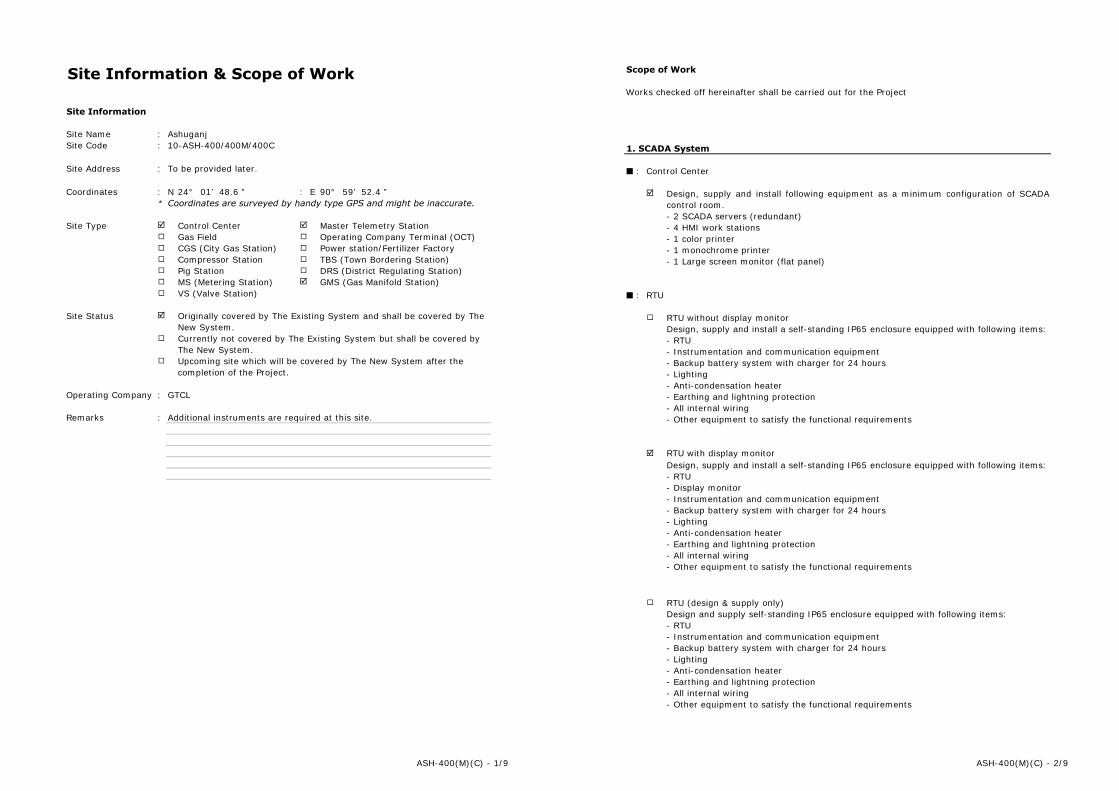
Site Information & Scope of Work
Site Information
Site Name :Site Code :
Site Address :
Coordinates : N : E* Coordinates are surveyed by handy type GPS and might be inaccurate.
Site Type Control Center Master Telemetry StationGas Field Operating Company Terminal (OCT)CGS (City Gas Station) Power station/Fertilizer FactoryCompressor Station TBS (Town Bordering Station)Pig Station DRS (District Regulating Station)MS (Metering Station) GMS (Gas Manifold Station)VS (Valve Station)
Site Status
Operating Company :
Remarks : Additional instruments are required at this site.
Ashuganj10-ASH-400/400M/400C
To be provided later.
24° 01’ 48.6 ” 90° 59’ 52.4 ”
Originally covered by The Existing System and shall be covered by TheNew System.Currently not covered by The Existing System but shall be covered byThe New System.Upcoming site which will be covered by The New System after thecompletion of the Project.
GTCL
ASH-400(M)(C) - 1/9
Scope of Work
Works checked off hereinafter shall be carried out for the Project
1. SCADA System
■ : Control Center
■ : RTU
RTU with display monitorDesign, supply and install a self-standing IP65 enclosure equipped with following items:- RTU- Display monitor- Instrumentation and communication equipment- Backup battery system with charger for 24 hours- Lighting- Anti-condensation heater- Earthing and lightning protection- All internal wiring- Other equipment to satisfy the functional requirements
RTU (design & supply only)
Design, supply and install following equipment as a minimum configuration of SCADAcontrol room.- 2 SCADA servers (redundant)- 4 HMI work stations- 1 color printer- 1 monochrome printer- 1 Large screen monitor (flat panel)
RTU without display monitorDesign, supply and install a self-standing IP65 enclosure equipped with following items:- RTU- Instrumentation and communication equipment- Backup battery system with charger for 24 hours- Lighting- Anti-condensation heater- Earthing and lightning protection- All internal wiring- Other equipment to satisfy the functional requirements
Design and supply self-standing IP65 enclosure equipped with following items:- RTU- Instrumentation and communication equipment- Backup battery system with charger for 24 hours- Lighting- Anti-condensation heater- Earthing and lightning protection- All internal wiring- Other equipment to satisfy the functional requirements
ASH-400(M)(C) - 2/9
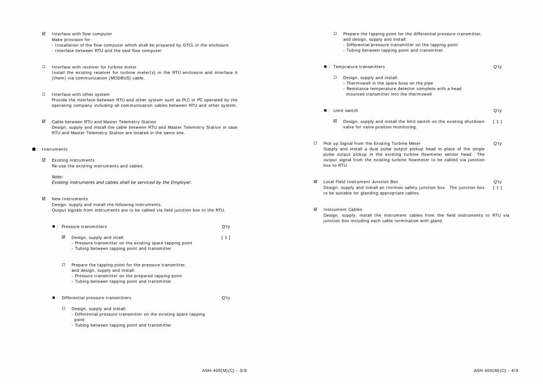
■ : Instruments
■ : Pressure transmitters
■ : Differential pressure transmitters
New InstrumentsDesign, supply and install the following instruments.Output signals from instruments are to be cabled via field junction box to the RTU.
Design, supply and intall:- Pressure transmitter on the existing spare tapping point- Tubing between tapping point and transmitter
Q'ty
[ 1 ]
Prepare the tapping point for the pressure transmitter,and design, supply and install:- Pressure transmitter on the prepared tapping point- Tubing between tapping point and transmitter
Design, supply and install:- Differential pressure transmitter on the existing spare tapping point- Tubing between tapping point and transmitter
Provide the interface between RTU and other system such as PLC or PC operated by theoperating company including all communication cables between RTU and other system.
Interface with other system
Q'ty
Existing instrumentsRe-use the existing instruments and cables.
Note:Existing instruments and cables shall be serviced by the Employer.
Interface with flow computerMake provision for:- Installation of the flow computer which shall be prepared by GTCL in the enclosure- Interface between RTU and the said flow computer
Cable between RTU and Master Telemetry StationDesign, supply and install the cable between RTU and Master Telemetry Station in caseRTU and Master Telemetry Station are located in the same site.
Interface with receiver for turbine meterInstall the existing receiver for turbine meter(s) in the RTU enclosure and interface it(them) via communication (MODBUS) cable.
ASH-400(M)(C) - 3/9
■ : Temprature transmitters
■ : Limit switch
Supply and install a dual pulse output pickup head in place of the singlepulse output pickup in the existing turbine flowmeter sensor head. Theoutput signal from the existing turbine flowmeter to be cabled via junctionbox to RTU.
Local Field Instrument Junction Box[ 1 ]
Q'ty
Pick up Signal from the Existing Turbine Meter
Design, supply and install:- Thermowell in the spare boss on the pipe- Resistance temperature detector complete with a head mounted transmitter into the thermowell
[ 1 ]
Q'ty
Design, supply and install the limit switch on the existing shutdownvalve for valve position monitoring.
Q'ty
Prepare the tapping point for the differential pressure transmitter,and design, supply and install:- Differential pressure transmitter on the tapping point- Tubing between tapping point and transmitter
Design, supply, install the instrument cables from the field instruments to RTU viajunction box including each cable termination with gland.
Design, supply and install an Intrinsic safety junction box. The junction boxto be suitable for glanding appropriate cables.
Instrument Cables
Q'ty
ASH-400(M)(C) - 4/9

2. Communication System
■ : Master Telemetry Station (Former Microwave Radio Station)
Removal of existing communication system
Radio equipment to connect Master Telemetry Station with Provider's Access Point
Master telemetry equipment
Radio equipment to connect Master Telemetry Station with OCT
Radio equipment to connect Provider's Access Point with Master Telemetry Station
Network equipment
Network cable to OCT
■ : IP PBX System
IP PBX main unit
Extension telephone set
Design, supply and install IP PBX main unit with necessary accessories and spare parts.
Design, supply and install IP radio equipment at nearest BTCL's access point to connectBTCL's AP with Master Telemetry Station, including all necessary cables, accessories andthe antenna with monopole.
Design, supply and install network cable between Master Telemetry Station and OCTwhich shall be installed within the same site.
Remove and dispose following existing items used for microwave transmission system:- Microwave equipment/facilities in the radio equipment room- Antenna mounted on the existing tower- Cables between radio equipment room and existing tower
Design, supply and install master telemetry equipment at existing radio equipmentroom to connect with slave telemetry equipment, including all necessary cables,accessories and the antenna to be mounted on the existing tower.
Design, supply and install IP radio equipment at radio equipment room to connectMaster Telemetry Station with Operating Company Terminal (OCT) at another site,including all necessary cables, accessories and the antenna to be mounted on theexisting tower.
Design, supply and install IP radio equipment at existing radio equipment room toconnect Master Telemetry Station with nearest Provider's Access Point (BTCL's AP),including all necessary cables, accessories and the antenna to be mounted on theexisting tower.
Design, supply and install all necessary Network equipment at radio equipment room ofMaster telemetry station as well as at nearest BTCL's access point.
Q'tyDesign, supply and install extension telephone set(s) with required cables. [ 20 ]
ASH-400(M)(C) - 5/9
3. Electrical Works
■ : Power Supply to RTU
■ : Backup Batteries for Radio Equipment at Master Station
■ : Replacement of Air conditioner at Radio room of Master Station
■ : Supply of Portable Engine Generator
Electrical power shall be supplied to RTU from existing PDB, and existing power cableshall be re-used.
Design, supply and intall power controller and power cable to RTU at remote site whereelectrical power is supplied from existing solar panel.
Remove and dispose existing window type air conditioner at raido room, and Supply &install new air conditioner suitably selected to maintain the specified temperature andhumidity of radio room.
Design, supply and install MCB box for the power supply to RTU including all cables fromexisting PDB to MCB box and from MCB box to RTU.
[ 1 ]
Q'ty
Supply of the petrol and/or diesel driven 1 kVA portable engine generatorfor the maintenance of remote site(s) without commercial power supply.
Remove and dispose existing backup batteries for radio equipment.Supply & install new backup batteries with charger suitable to backup new radioequipment for 48 hours.
Design, supply and install new solar panel, power controller and power cable to RTU.
ASH-400(M)(C) - 6/9
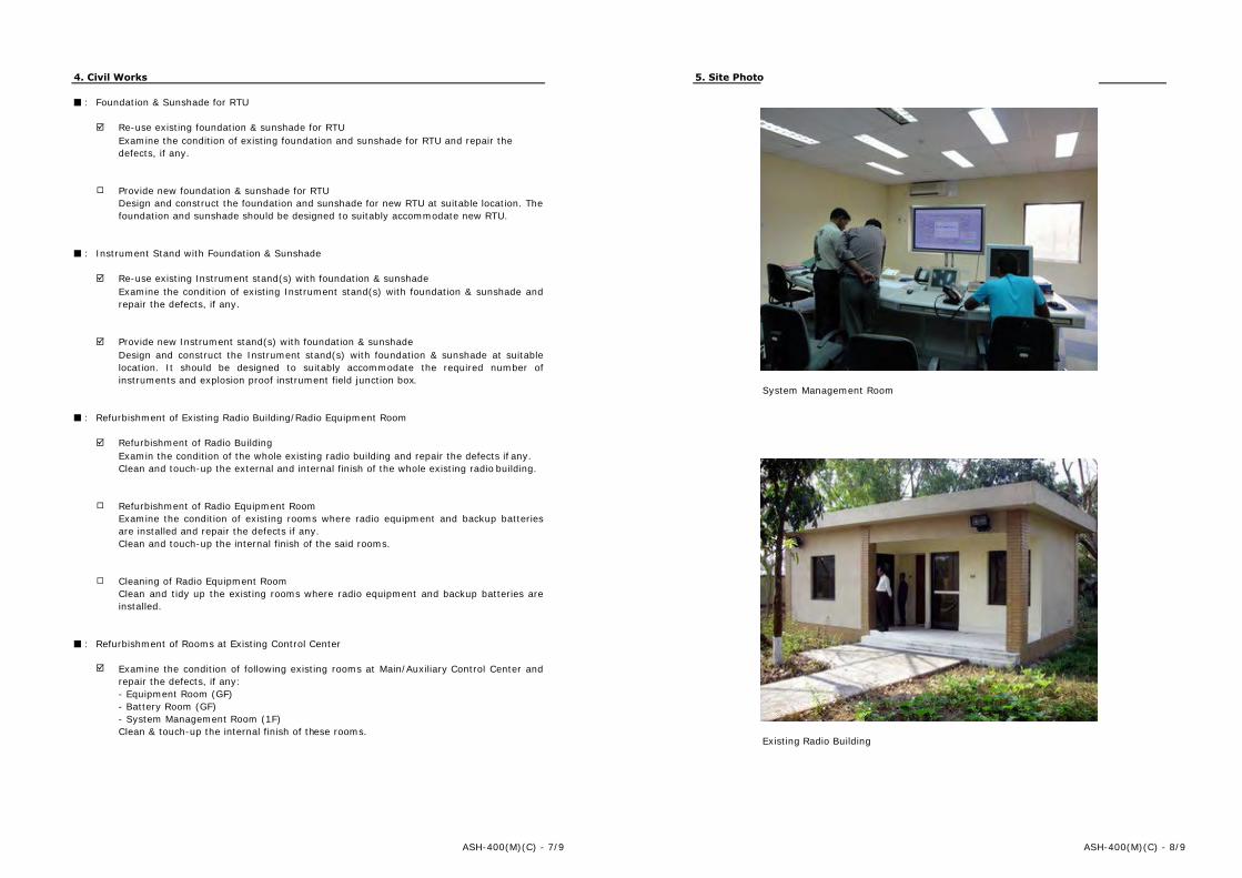
4. Civil Works
■ : Foundation & Sunshade for RTU
■ : Instrument Stand with Foundation & Sunshade
■ : Refurbishment of Existing Radio Building/Radio Equipment Room
■ : Refurbishment of Rooms at Existing Control Center
Clean and tidy up the existing rooms where radio equipment and backup batteries areinstalled.
Provide new Instrument stand(s) with foundation & sunshadeDesign and construct the Instrument stand(s) with foundation & sunshade at suitablelocation. It should be designed to suitably accommodate the required number ofinstruments and explosion proof instrument field junction box.
Re-use existing foundation & sunshade for RTUExamine the condition of existing foundation and sunshade for RTU and repair thedefects, if any.
Provide new foundation & sunshade for RTU
Re-use existing Instrument stand(s) with foundation & sunshadeExamine the condition of existing Instrument stand(s) with foundation & sunshade andrepair the defects, if any.
Refurbishment of Radio Equipment Room
Cleaning of Radio Equipment Room
Design and construct the foundation and sunshade for new RTU at suitable location. Thefoundation and sunshade should be designed to suitably accommodate new RTU.
Refurbishment of Radio BuildingExamin the condition of the whole existing radio building and repair the defects if any.Clean and touch-up the external and internal finish of the whole existing radio building.
Examine the condition of existing rooms where radio equipment and backup batteriesare installed and repair the defects if any.Clean and touch-up the internal finish of the said rooms.
Examine the condition of following existing rooms at Main/Auxiliary Control Center andrepair the defects, if any:- Equipment Room (GF)- Battery Room (GF)- System Management Room (1F)Clean & touch-up the internal finish of these rooms.
ASH-400(M)(C) - 7/9
5. Site Photo
paste site photo
Existing Radio Building
System Management Room
paste site photo
ASH-400(M)(C) - 8/9

6. Site Layout
See attached Layout Plan.
ASH-400(M)(C) - 9/9
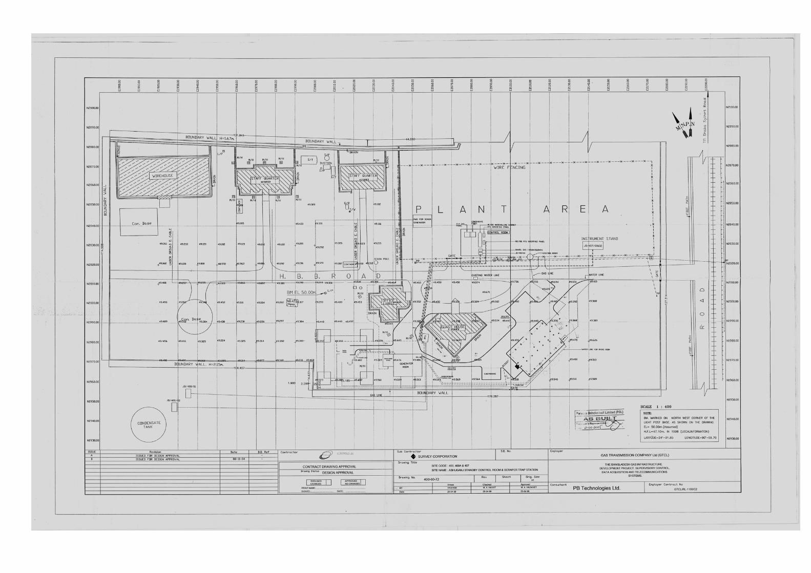

Site Information & Scope of Work
Site Information
Site Name :Site Code :
Site Address :
Coordinates : N : E* Coordinates are surveyed by handy type GPS and might be inaccurate.
Site Type Control Center Master Telemetry StationGas Field Operating Company Terminal (OCT)CGS (City Gas Station) Power station/Fertilizer FactoryCompressor Station TBS (Town Bordering Station)Pig Station DRS (District Regulating Station)MS (Metering Station) GMS (Gas Manifold Station)VS (Valve Station)
Site Status
Operating Company :
Remarks : Additional instruments are required at this site.
Originally covered by The Existing System and shall be covered by TheNew System.Currently not covered by The Existing System but shall be covered byThe New System.Upcoming site which will be covered by The New System after thecompletion of the Project.
41.9 ”
BGFCL
Titas Gas Field Location 110-ASH-201
To be provided later.
23° 49.2 ” 91° 06’59’
ASH-201 - 1/8
Scope of Work
Works checked off hereinafter shall be carried out for the Project
1. SCADA System
■ : RTU
Design, supply and install a self-standing IP65 enclosure equipped with following items:- RTU- Display monitor- Instrumentation and communication equipment- Backup battery system with charger for 24 hours- Lighting- Anti-condensation heater- Earthing and lightning protection- All internal wiring- Other equipment to satisfy the functional requirements
RTU (design & supply only)
Interface with flow computerMake provision for:- Installation of the flow computer which shall be prepared by GTCL in the enclosure- Interface between RTU and the said flow computer
Interface with receiver for turbine meterInstall the existing receiver for turbine meter(s) in the RTU enclosure and interface it(them) via communication (MODBUS) cable.
RTU without display monitorDesign, supply and install a self-standing IP65 enclosure equipped with following items:- RTU- Instrumentation and communication equipment- Backup battery system with charger for 24 hours- Lighting- Anti-condensation heater- Earthing and lightning protection- All internal wiring- Other equipment to satisfy the functional requirements
Design and supply self-standing IP65 enclosure equipped with following items:- RTU- Instrumentation and communication equipment- Backup battery system with charger for 24 hours- Lighting- Anti-condensation heater- Earthing and lightning protection- All internal wiring- Other equipment to satisfy the functional requirements
RTU with display monitor
ASH-201 - 2/8
■ : Instruments
■ : Pressure transmitters
■ : Differential pressure transmitters
■ : Temprature transmitters
Design, supply and install:- Thermowell in the spare boss on the pipe- Resistance temperature detector complete with a head mounted transmitter into the thermowell
Prepare the tapping point for the differential pressure transmitter,and design, supply and install:- Differential pressure transmitter on the tapping point- Tubing between tapping point and transmitter
Q'ty
[ 1 ]
Design, supply and install the cable between RTU and Master Telemetry Station in caseRTU and Master Telemetry Station are located in the same site.
Q'ty
[ 1 ]
Prepare the tapping point for the pressure transmitter,and design, supply and install:- Pressure transmitter on the prepared tapping point- Tubing between tapping point and transmitter
Re-use the existing instruments and cables.
Note:Existing instruments and cables shall be serviced by the Employer.
New InstrumentsDesign, supply and install the following instruments.Output signals from instruments are to be cabled via field junction box to the RTU.
Design, supply and intall:- Pressure transmitter on the existing spare tapping point- Tubing between tapping point and transmitter
Q'ty
Provide the interface between RTU and other system such as PLC or PC operated by theoperating company including all communication cables between RTU and other system.
Interface with other system
Existing instruments
Cable between RTU and Master Telemetry Station
[ 2 ]Design, supply and install:- Differential pressure transmitter on the existing spare tapping point- Tubing between tapping point and transmitter
ASH-201 - 3/8
■ : Limit switch
[ 1 ]
Pick up Signal from the Existing Turbine Meter Q'ty
Design, supply and install the limit switch on the existing shutdownvalve for valve position monitoring.
Design, supply, install the instrument cables from the field instruments to RTU viajunction box including each cable termination with gland.
Design, supply and install an Intrinsic safety junction box. The junction boxto be suitable for glanding appropriate cables.
Instrument Cables
Q'ty
Supply and install a dual pulse output pickup head in place of the singlepulse output pickup in the existing turbine flowmeter sensor head. Theoutput signal from the existing turbine flowmeter to be cabled via junctionbox to RTU.
Local Field Instrument Junction Box
Q'ty
ASH-201 - 4/8
2. Communication System
■ : Slave Telemetry System
Removal of existing slave telemetry equipment
Slave Telemetry Equipment
Slave Telemetry Equipment (design & supply only)
Existing monopole
New monopole
New monopole (design & supply only)
Design and supply new slave telemetry equipment in the RTU enclosure, includingcables and antenna.
Design and supply new monopole to mount new antenna.
Remove and dispose the existing slave telemetry system including antenna and cable.
Design, supply and install new slave telemetry equipment in the RTU enclosure,including cables and antenna.
Re-use existing monople to mount new antenna.
Design, supply and install new monopole with foundation to mount new antenna.
ASH-201 - 5/8
3. Electrical Works
■ : Power Supply to RTU
4. Civil Works
■ : Foundation & Sunshade for RTU
■ : Instrument Stand with Foundation & Sunshade
Provide new Instrument stand(s) with foundation & sunshadeDesign and construct the Instrument stand(s) with foundation & sunshade at suitablelocation. It should be designed to suitably accommodate the required number ofinstruments and explosion proof instrument field junction box.
Re-use existing foundation & sunshade for RTUExamine the condition of existing foundation and sunshade for RTU and repair thedefects, if any.
Provide new foundation & sunshade for RTU
Re-use existing Instrument stand(s) with foundation & sunshadeExamine the condition of existing Instrument stand(s) with foundation & sunshade andrepair the defects, if any.
Design, supply and install new solar panel, power controller and power cable to RTU.
Design and construct the foundation and sunshade for new RTU at suitable location. Thefoundation and sunshade should be designed to suitably accommodate new RTU.
Design, supply and install MCB box for the power supply to RTU including all cables fromexisting PDB to MCB box and from MCB box to RTU.
Electrical power shall be supplied to RTU from existing PDB, and existing power cableshall be re-used.
Design, supply and intall power controller and power cable to RTU at remote site whereelectrical power is supplied from existing solar panel.
ASH-201 - 6/8
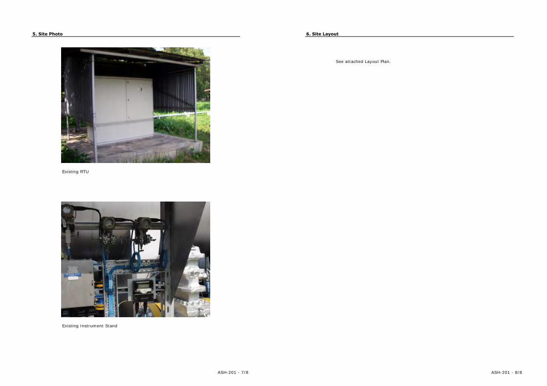
5. Site Photo
paste site photo
Existing Instrument Stand
Existing RTU
paste site photo
ASH-201 - 7/8
6. Site Layout
See attached Layout Plan.
ASH-201 - 8/8