
The Study of II-VI Semiconductor Nanocrystal Sensitized Solar Cells
49
The Study of II-VI Semiconductor Nanocrystal Sensitized Solar Cells Chunze Yuan Licentiate Thesis in Theoretical Chemistry and Biology School of Biotechnology Royal Institute of Technology Stockholm, Sweden 2012
Transcript of The Study of II-VI Semiconductor Nanocrystal Sensitized Solar Cells

The Study of II-VI Semiconductor Nanocrystal
Sensitized Solar Cells
Chunze Yuan
Licentiate Thesis in Theoretical Chemistry and Biology
School of Biotechnology
Royal Institute of Technology
Stockholm, Sweden 2012

The study of II-VI semiconductor nanocrystal sensitized solar cells
© Chunze Yuan, 2012
ISBN 978-91-7501-300-8
ISSN 1654-2312
TRITA-BIO Report 2012:5

Abstract
Semiconductor nanocrystals, also referred to as quantum dots (QDs), have been the focus of great
scientific and technological efforts in solar cells, as a result of their advantages of low-cost,
photostability, high molar extinction coefficients and size-dependent optical properties. Due to
the multi-electron generation effect, the theoretically maximum efficiency of quantum dots-
sensitized solar cells (QDSCs) is as high as 44%, which is much higher than that of dye-
sensitized solar cells (DSCs). Thus QDSCs have a clear potential to overtake the efficiency of all
other kinds of solar cells.
In recent years, the efficiency of QDSCs has been improved very quickly to around 5%. It is
however still much lower than that of DSCs. The low efficiency is mostly caused by the high
electron loss between electrolyte and electrodes and the lack of an efficient electrolyte. In this
thesis, we have been working to enhance the performance of QDSCs with II-VI group
nanocrystals by increasing the electron injection efficiency from QDs to TiO2 and developing
new redox couples in electrolyte.
To increase the electron injection, firstly, colloidal ZnSe/CdS type-II QDs were synthesized and
applied for QDSCs for the first time, whose photoelectron and photohole are located on CdS shell
and ZnSe core, respectively. The spatial separation between photoelectron and photohole can
effectively enhance the charge extraction efficiency, facilitating electron injection, and also
effectively expand the absorption spectrum. All these characteristics contribute to the high photon
to current conversion efficiency. Furthermore, a comparison between the performances of
ZnSe/CdS and CdS/ZnSe QDs shows that the electron distribution is important for the electron
injection of the QDs in QDSCs. Secondly, colloidal CdS/CdSe quantum rods (QRs) were applied
to a quantum rod-sensitized solar cell (QRSCs) that showed a higher electron injection efficiency
than analogous QDSCs. It is concluded that reducing the carrier confinement dimensions of
nanocrystals can improve electron injection efficiency of nanocrystal sensitized solar cells.
In this thesis, two types of organic electrolytes based McMT-/BMT and TMTU/TMTU-TFO were
used for QDSCs. By reducing the charge recombination between the electrolyte and counter
electrode, fill factor (FF) of these QDSCs was significantly improved. At the same time, the
photovoltages of the QDSCs were remarkably increased. As a result, the overall conversion
efficiency of QDSCs based on the new electrolytes was much higher than that with a commonly
used inorganic electrolyte.
In addition, CdS QDSCs on NiO photoelectrode were studied which shows a n-type photovoltaic
performance. This performance is attributed to the formation of a thin Cd metal film before CdS
QDs formation on NiO. Since the CB edge of CdS sits between the Fermi level and the CB edge
of Cd metal, a much strong electron transfer between Cd and CdS QD is obtained, resulting in the
observed n-type photovoltaic performance of these CdS/NiO QDSCs.
Keywords: quantum dots, quantum rods, nanocrytals, solar cells, colloidal, type-II, electron
injection, organic electrolyte.

Abbreviations
QDs Quantum dots
QRs Quantum rods
NCs Nanocrystals
QY Quantum yield
PL Photoluminescence
DSCs Dye-sensitized solar cells
QDSCs Quantum dots-sensitized solar cells
QRSCs Quantum rods-sensitized solar cells
McMT-/BMT A type of organic redox couple for electrolyte
TMTU/TMTU-TFO A type of organic redox couple for electrolyte
Jsc Short circuit current density
Voc Open-circuit voltage
FF Fill factor
η The efficiency of a solar cell
IPCE Incident photon to current conversion efficiency
APCE Absorbed photon to current conversion efficiency
UV-Vis Ultraviolet-visible
J-V Current density-voltage
λ Wavelength of light
Eg Bandgap
HOMO Highest occupied molecular orbital
LUNO Lowest unoccupied molecular orbital
TEM Transmission electron microscopy
SEM Scanning electron microscope
CB Conduction band
VB Valence band
AM Air Mass

TiO2 Titanium dioxide
NiO Nickel Oxide
NHE Normal hydrogen electrode
ODE Octadecene
TOP Trioctylphosphine
OA Oleic acid
ODA 1-octadecanamine
FTO Fluoride-doped tin oxide
MPA Mercaptopropionic acid
CBD Chemical bath deposition
SILAR Successive ion layer adsorption reactions

List of Publications
This thesis is based on the following papers, referred to in text by their Roman numerals
I-V:
I. Solar cells sensitized with type-II ZnSe–CdS core/shell colloidal quantum dots
Zhijun Ning, Haining Tian, Chunze Yuan, Ying Fu, Haiyan Qin, Licheng Sun and
Hans Ågren
Chem. Commun., 2011, 47, 1536-1538.
II. Quantum rod-sensitized solar cells
Zhijun Ning, Chunze Yuan, Haining Tian, Peter Hedström, Licheng Sun and Hans
Ågren
ChemSusChem, 2011, 4, 1741-1744.
III. Type-II colloidal quantum dot sensitized solar cells with a thiourea based
organic redox couple
Zhijun Ning, Chunze Yuan, Haining Tian, Ying Fu, Lin Li, Licheng Sun and Hans
Ågren
J. Mater. Chem., 2012, 22, 6032-6037.
IV. Pure organic redox couple for quantum-dot-sensitized solar cell
Zhijun Ning, Haining Tian, Chunze Yuan, Ying Fu, Licheng Sun and Hans Ågren
Chem. Eur. J., 2011, 17, 6330 -6333.
V. Study of CdS quantum dot solar cells directly deposited on p-type NiO
photoelectrodes
Chunze Yuan, Lin Li, Zhijun Ning, Licheng Sun and Ying Fu
Manuscript.
Contribution to the Publications
I took part of the work on the synthesis, measurements, discussion, analysis and writing
for paper II and III.
I took part of the work on the synthesis, measurements, discussion, analysis for paper I
and IV.
I took major contribution to synthesis, measurements, discussion, analysis and writing for
paper V.

Table of Contents
1 Introduction ........................................................................................................................... - 1 -
2 Overview of Solar Energy ..................................................................................................... - 3 -
2.1 Energy crisis and renewable energy resources ............................................................ - 3 -
2.2 Solar energy and solar constant ................................................................................... - 4 -
2.3 Utilization of solar energy and development of solar cells ......................................... - 6 -
3 Semiconductor Nanocrystals ................................................................................................ - 9 -
3.1 QDs and the classification ......................................................................................... - 10 -
3.2 The characteristics of QDs ........................................................................................ - 11 -
3.2.1 Size-dependent effect ........................................................................................ - 11 -
3.2.2 Multiple exciton generation ............................................................................... - 13 -
3.3 Type-I and type-II of core/shell QDs ........................................................................ - 14 -
3.4 Quantum rods ............................................................................................................ - 15 -
4 Quantum Dots-sensitized Solar Cells ................................................................................. - 17 -
4.1 Working principle and basic components of QDSCs ................................................ - 17 -
4.1.1 Working principle .............................................................................................. - 17 -
4.1.2 Basic components .............................................................................................. - 19 -
4.2 Synthesis of colloidal QDs and QRs ......................................................................... - 21 -
4.2.1 Synthesis of QDs ............................................................................................... - 21 -
4.2.2 Synthesis of QRs ............................................................................................... - 23 -
4.3 Fabrication and assembly of QDSCs ......................................................................... - 23 -
4.3.1 Fabrication of TiO2 and NiO photoelectrode ..................................................... - 23 -
4.3.2 QDs deposition on photoelectrode .................................................................... - 24 -
4.3.3 Fabrication of counter electrode ........................................................................ - 25 -
4.3.4 Assembly of QDSCs .......................................................................................... - 25 -
4.4 Characterization of QDs and QDSCs ........................................................................ - 26 -
4.4.1 Optical characterization of QDs ........................................................................ - 26 -
4.4.2 Characterization of photovoltaic performance of QDSCs ................................. - 26 -
5 Results and Conclusions ..................................................................................................... - 29 -
5.1 The study of type-II QDs sensitized solar cells (Paper I) ......................................... - 29 -
5.2 The study of quantum rods-sensitized solar cells (Paper II) ..................................... - 30 -

5.3 The study of QDSCs based on pure organic electrolyte (Paper III and IV) .............. - 31 -
5.4 The study of p-type QDSCs (Paper V) ...................................................................... - 33 -
6 Future outlook ..................................................................................................................... - 35 -
Acknowledgements .................................................................................................................. - 37 -
References ................................................................................................................................ - 38 -

- 1 -
Chapter 1
Introduction
Accompanied by the extensive use of traditional fossil energy sources, environmental
pollution and energy crisis have become major issues facing humanity so that
development and utilization of new energy are imminent. Human has been able to
successfully use a variety of green energy resources, for instance, tidal, geothermal, wind
and solar energy. However, among various energy resources, wind, geothermal and tidal
energy were limited to the civil popularization due to geographical and other factors.
Solar energy as a new kind of energy has the characteristics of no pollution, basically no
geographical restrictions, rich reserves, use diversification and so forth. If we can use
solar energy effectively, all the energy of the human activities maybe can be provided by
solar.
At present, the main method of utilization of solar energy is the conversion of solar
energy into other energy sources. In 1954 the silicon solar cell developed by Bell marks
that human can make solar energy converse into electrical energy for use, which is
epoch-making significance.1 However, it is not suitable for large-scale civilian since this
type of battery has the more stringent requirements for raw materials and production
process. Although the subsequent development of polysilicon and amorphous silicon
solar cells is relatively simple in production process, high prices still can’t meet the large-
scale use.
In 1991, Professor Grätzel reported a new low-cost chemical solar cell using organic dye
absorbed nanocrystal titanium dioxide (TiO2) film as the photoanode, known as Grätzel
cells or dye-sensitized solar cells (DSCs),2 which gave a photoelectric conversion
efficiency of 7% under simulated sunlight irradiation. After development in twenty years,
now the efficiency of this kind of solar cells has more than 12%.3 Because of the simple
production process, much lower cost relative to silicon cells and the lifetime of more than
15 years, this type of cells provides a feasible approach for large-scale utilization of solar
energy.4
In recent decades, quantum dots (QDs), also referred as semiconductor nanocrystals, have
been the research focus in biomarkers,5,6
light-emitting diodes7 and photovoltaic devices,
8
due to their unique electronic and luminescent properties. In particular, quantum dots-
sensitized solar cells (QDSCs) are of great interest because of their excellent performance
of low-cost, photostability, high molar extinction coefficients and size-dependent optical
properties.9-12
Furthermore their special multi-electron generation character can enable

- 2 -
the theoretically maximum efficiency to be as high as 44%,13
much higher than that of
dye based DSCs. Although QDSCs have been developed very quickly, their efficiency of
around 5% is still much lower than that of DSCs.14,15
This mainly results from the high
electron loss between electrolyte and electrodes (photoelectrode and counter electrode).
Thus, to increase the conversion efficiency, most efforts have been concentrated to
develop QDs properties in the regions of the electron transport rate and light harvesting
ability, to improve catalytic ability of counter electrode and to decrease the charge
recombination.
The aim of this thesis has been to improve the performance of QDSCs with II-VI group
QDs by optimizing the size, structure and shape of QDs, and using new type electrolyte.
Thus, my thesis works are divided into two parts. One part has focused on the chemical
synthesis of type-II QDs and quantum rods (QRs) applied in QDSCs in order to enhance
the conversion efficiency via increasing the electron extraction efficiency and electron
injection efficiency, respectively. The second part has been committed to try some
organic redox couples in electrolyte of QDSCs. In addition, we also made some studies
on p-type QDSC.

- 3 -
Chapter 2
Overview of Solar Energy
2.1 Energy crisis and renewable energy resources
In the 21st century, human will face a major challenge to achieve sustainable economic
and social development under the astringent requirements of the limited resources and
environmental protection. This has become a global hot issue. Energy issue will become
more prominent due to not only the lack of conventional energy but also a series of
adverse consequences brought by the consumption of fossil fuels.
1. Energy shortage
The limitation and uneven distribution of conventional energy sources cause that
the energy supply of most counties can’t meet the needs of economic development.
Therefore, human will face the exhaustion of fossil fuel sooner or later if not as
soon as possible to resolve the issue to find alternative energy.
2. Environmental pollution
Currently, due to the burning of fossil fuels, huge sulfur and some poisonous
substances are emitted into the sky every year, bringing the solemn pollution of
atmospheric environment, soil and water. Due to these issues, eventually human
have to change the energy structure and rely on the use of solar and other
renewably clean energies.
3. Greenhouse effect
The use of fossil fuels also causes the greenhouse effect due to large amounts of
CO2 emissions, resulting in global climate alteration. Its impact has been even
more serious than the environmental pollution. Now this problem has been already
referred to the global agenda.
Therefore, to solve the energy problem and achieve sustainable development, human
have to rely on scientific and technological process and large-scale development to utilize
renewable and clean energies. Renewable energies refer to the renewable, sustainable and
inexhaustible resources in nature, which is (almost) harmless to the environment, widely
distributed and suitable for in situ exploitation and utilization. These mainly include solar,
wind, hydro, biomass, geothermal and tidal energy. World renewable energy is now in a

- 4 -
stage of rapid development and some technology has been at or near the level of
commercialization. Currently, wind power technology is relatively mature. From 2011
report of the American Wind Energy Association,16
wind power costs about 5~6
cents/kWh, with which wind energy can compete with nuclear power, coal and gas under
the same conditions and there is decline in the cost. Although wind energy has the
advantage of low cost and no pollution, there are still the limitations of noise and
geography. Solar energy with its unique characters and gradually economic advantage
will have considerable development on exploitation and utilization in 21st century.
2.2 Solar energy and solar constant
Solar energy is generated by the continuous fusion reactions inside the Sun. The total
energy emitted from the Sun is about 3.75× 1026
W, one of 2.2 billion of which can be
obtained by the Earth. If the batteries with 10% of photoelectric conversion efficiency
cover 0.1% of the Earth’s surface, the produced energy can meet all human’s energy
needs.17
The main characteristics of the exploitation and utilization of solar energy are as
follows.
1. “Infinity” reserve
The solar energy reaching the Earth’s surface within one year is one million times
of the current proven reserves of the world’s major energy resource. The sun’s
lifetime is at least 4 billion years. Relative to the history of mankind, the sun can
continuously supply the Earth with the energy in infinite time. Thus, compared to
finite conventional energy, the reserve of solar energy is “infinite” and
inexhaustible. This decides that solar energy will be the most effective resource to
solve the shortage and depletion of conventional energy.
2. Universality of the existence
Although the differences in latitudes and climatic conditions cause the uneven
solar radiation, relative to other energy resource, solar energy is available in most
areas on. This provides a bright future to solve the energy problem for the
countries and regions that are lack of conventional energy.
3. Absolutely clean utilization
Like wind, tidal and other clean energies, the utilization of solar energy almost
doesn’t produce any pollution. Combined with the infinite reserve, it is the ideal
alternative energy of human.

- 5 -
Since the Sun-Earth distance (an average distance of 1.5×10⁸ km) is very large, the
distance can be considered to a constant and thus the intensity of solar radiation outside
the Earth’s atmosphere is almost a constant, called the “solar constant” with the value of
1.338~1.418 kW/m2.18
Fig. 2.1 Solar radiation spectrum at the top of atmosphere (AM 0) and at sea level (AM 1.5)
Sunlight reaches the Earth’s surface through the atmosphere by the absorption of the
various components of the atmosphere and the reflection of clouds. The average energy is
about 1 kW/m2 while solar energy reaches the Earth’s surface in the form of direct and
diffuse light finally. Once the photons enter the atmosphere, the continuous solar
spectrum will become into spectral bands due to absorption and scattering of water,
carbon dioxide and other substances. In the spectrum of solar radiation, 99% of energy
concentrates between 276 nm and 4960 nm (Fig. 2.1).
Fig. 2.2 The path length in units of Air Mass
Due to the different angles of incidence sunlight resulting in different thickness of passed
atmosphere, Air Mass (AM) is usually used to represent the incident path of the

- 6 -
sunlight.19
When the vertical irradiation of sunlight outside the atmosphere, AM is 0;
when the angle between incident sunlight and the ground is 90 º, AM is 1, as shown in
Fig. 2.2. The zenith angel θ is the angel between the connection line of any point of sea
level with the sun and sea level. The relationship between θ and AM is expressed as
follows:
AM = 1/sin θ (2.1)
Generally speaking, the performances of solar devices are measured under simulated
solar illumination of AM 1.5 with an intensity of 1000 kW/m2.
2.3 Utilization of solar energy and development of solar cells
Human have been constantly looking for effective utilization of solar energy for a long
time. Especially in recent years solar energy has been vigorous developed due to the
problems of depletion of traditional energy and environmental pollution. The methods of
utilization of solar cells are the following.17
1. Photothermal conversion
Heat utilization occupies an important position in the technology of solar energy.
Solar collectors with air or liquid as heat transfer medium absorb and store thermal
energy for utilization. Development of new efficient solar collector is one of the
future directions of thermal utilization of solar energy.
2. Photochemical conversion
This conversion relies mainly on use of solar catalyst producing other chemical
substances or energy carriers by solar illumination. For example, hydrogen can be
manufactured by photochemical cells.
3. Photoelectric conversion
This conversion is achieved by the employment of solar cells, which are
semiconductor optoelectronic devices based on the photoelectric or photochemical
effect that directly convert sunlight into electrical energy. Since the 21st century,
world’s solar photovoltaic industry has been developed and the market has been
expanded rapidly. Photovoltaic power is likely to fundamentally change the energy
production, supply and consumption patterns and even bring revolutionary changes
to energy development in the near future.
The solar cell is generated by the photovoltaic principle, which has experienced a long
course of development since the 18th
century.20
In 1839, Becquerel first discovered the

- 7 -
photoelectric effect by the experiment that CuO or AgX coated metal electrode can
generate electricity under illumination. Later, British scientist, Adams and Day obtained
1% of photoelectric conversion efficiency by the illumination of the selenium. After the
continuous efforts of scientists from various countries, in 1941 the first practical silicon
solar cell was born at Bell Labs, making the forming of solar cells. By the technological
advances the cost of silicon solar cell has decreased a little to meet the needs in specific
range, such as military, aerospace and parts of civilian power supply.
At present, solar cells mainly include the following types according to the different
materials used, they are silicon solar cells, thin film solar cells, polymer solar cells,
organic solar cells and sensitized solar cells.17
Although solar cells based on
semiconductor silicon and inorganic semiconductor compounds have the higher
conversion efficiency, their complex production process and high cost limit their
development. In recent years, much effort has been given to sensitized solar cells based
on nanocrystal TiO2 due to low cost. According to the different types of sensitized
materials, sensitized solar cells are divided into two types, dye-sensitized solar cells
(DSCs) with organic dye as photosensitizer and quantum dots-sensitized solar cells
(QDSCs) with QDs as photosensitizer. Comparing to DSCs, QDs have the potential to
enhance the cell stability, and their special multi-electron generation character can enable
the theoretically maximum efficiency to be as high as 44%,13
much higher than that of
DSCs.

- 8 -

- 9 -
Chapter 3
Semiconductor Nanocrystals
Semiconductor nanocrystals (NCs) are tiny light-emitting particles with typical
dimensions in the range of 1-100 nm depending on the materials. The NCs are the
materials located on the transition region at the junction of the molecule clusters and bulk
materials, resulting from the dramatic quantum confinement effects.21
When the radius of
nanocrystals is less than the Bohr radius of excitons (electron-hole pairs) in bulk
materials, the charge carriers become spatially confined and the continuous energy bands
of bulk semiconductor will split into discrete energy levels like molecules. The values of
energy levels are ultimately determined by the size of NCs. As a result, the optical and
electronic properties are also dependent on the size of NCs.
Fig. 3.1 The density of energy states of bulk materials, quantum wells, quantum rods and
quantum dots show the process of energy bands splitting from bulk to quantum dots.
As shown in Fig. 3.1, the energy of the bulk materials is continuous in three-dimensional
space. When the system is transited from bulk to QDs, the density of states will be
gradually reduced. When the charge carriers are confined by the quantum confinement in
one-dimensions, the energy is only continuous in the two-dimensional space, so the
materials are termed quantum wells or quantum films. Similarly, when the carriers are
confined in the two-dimensional space and the energy is only one-dimensionally
continuous, the materials are quantum wires or quantum rods (QRs). When the carriers
are confined in all three spatial dimensions, like the movement of carriers limited in a
‘small box’, these are quantum dots (QDs), whose energy is completely quantized. With
the size decreasing of the materials resulting in quantum effects, the structure and
property will shift from macro to micro. QDs have more obvious quantum effect than

- 10 -
quantum wells and quantum wires, resulting from the confinement of three-dimension.
The small size and large specific surface area of QDs lead to the quantum size effect and
unique optical properties. Since the works in this thesis mainly involved the application
of QDs on solar cells and also QDs are also frequently referred to as NCs, we will discuss
the properties of QDs.
3.1 QDs and the classification
In recent decades, due to the unique electronic and luminescent properties and the
applications in biological labeling, light emitting diodes and solar cells, QDs became the
focus of research attentions. QDs are a type of semiconductor NCs with a size range from
one to tens nanometers, consisting of several hundreds to a few thousands of atoms. QDs
can be synthesized by chemical methods, also known as colloidal QDs, which are coated
by a layer of organic surfactant molecules (also termed ‘ligands’) on the surface. Since
QDs were first discovered by Louis E. Brus in 1982,22 many types of QDs have been
developed, shown in Table 3.1.
Table 3.1 Classification of QDs
Single-core structure
II-VI CdS,23
CdSe,24,25
CdTe,26,27
ZnSe28
III-V InP,29,30
InAs,31
GaN32
IV-VI PbS,33
PbSe34
IV Ge,35
Si36
Core/shell structure
Type-I CdSe/ZnS,
37 InP/ZnS,
38,39 CdSe/CdS/ZnS,
40
CdSe/CdS/Cd0.5ZnS0.5/ZnS41
Type-II CdTe/ CdSe,42
CdSe/ZnTe,42
ZnSe/CdS43
Alloy ZnXCd1-XSe,44
HgXCd1-XTe45
In accordance to the type of material structures, QDs can be classified to single-core,
core-shells and alloy structured QDs. Furthermore single-core QDs are classified to II-VI,
III-V, IV-VI and IV by the elemental compositions. And core/shell QDs are classified to
type-I and type-II according to energy band structures of electrons and holes.43 The
core/shell structure consists of a core of semiconductor material and surrounds a 0.5-2 nm
thick layer of different semiconductors as the shells. Comparing to single-core structure,
core/shell structure can greatly improve the fluorescence quantum yield (QY) and
stability of QDs.41 Generally the QY is used to character the luminescence efficiency of
QDs, which is the ratio of emitted photons to absorbed photons through fluorescence.46
Different from core-shells QDs, alloy QDs have a homogeneous composition, like single-

- 11 -
core QDs, with three or more chemical elements, whose chemical stability and QY are
usually higher than those of single-core QDs.44
Of course, some core/shell QDs can also be classified by their elemental composition.
For example, ZnSe/CdS of type-II core/shell is totally made of the elements of II-VI
group. Thereby, it also can be classified to II-VI QDs. In this thesis, all of prepared QDs
belong to II-VI group.
3.2 The characteristics of QDs
3.2.1 Size-dependent effect
As shown in Fig. 3.2, the optical properties of QDs, i.e., photoluminescence (PL) and
absorption, show the unique size-dependent effect. With the gradual increase of the size
of CdSe QDs, absorption and fluorescence peaks red shift continuously. The smallest
CdSe QDs with a diameter of 1.6 nm show a blue emission light. The largest one with a
diameter of 8 nm emits red light. It is well known that this optical behavior of red shift is
caused by the decreasing of the QD bandgap (HOMO-LUNO, Eg). The decreasing of the
bandgap is leaded by increase the QD size.
Fig. 3.2 Red shift of UV-vis and PL spectra of colloidal CdSe QDs with the increase of the QD
size; The upper right corner shows the solutions of CdSe under UV excitation. The spectra
display the size-dependent effect on optical properties of QDs.

- 12 -
The size-dependent optical properties and bandgaps of semiconductor QDs are dependent
on quantum confinement. Based on this theory, QDs can be considered as an intermediate
material between molecules and bulk material, whose energy levels integrate some parts
of their characteristics (see Fig. 3.3). Due to the quantum confinement effect, when the
bulk semiconductor material gradually decreases its size to a critical size (Bohr radius),
the movement of the carriers will be strongly quantum limited. At the same time the
density of electronic states is changed from a continuous energy band of bulk materials
into a quasi-discrete energy level, similar to molecules. And the QD bandgap is increased
following the increase of the quantum confinement effect. The smaller size of QDs will
lead to the stronger quantum confinement effect. With the size of QDs decreases, the
increase of bandgap and the splitting energy band are more significantly, blue-shift of
optical spectrum is greater, and also the behavior becomes more like molecules. As a
result, the strong size-dependent optoelectronic properties of QDs make it possible to
tune the absorption and PL of QDs through a wide spectral window by tailing the size.
Fig. 3.3 Schematic representation of the size-dependence of the energy level structure and
bandgap of CdSe QDs resulting from quantum confinement effect.
Due to the size-dependent effect, the size of QDs has become an important parameter to
the development of QDs. The size can be exactly determined by transmission electron
microscopy (TEM) measurements. Researchers have also determined the QD sizes from
their absorption spectra. For the most popular QDs of CdS, CdSe and CdTe, Peng and co-
authors gave the empirical equations (shown below), which make the diameter D (nm) of
QDs as the function of the wavelength λ (nm) of the first excitonic absorption peak of
QDs.47
Currently, these equations are widely utilized to calculate the size of these three
types of QDs and the result values give well agreement with the experimental values.
CdS: ( ) ( ) (2.1)
( )

- 13 -
CdSe: ( ) ( ) (2.2)
( )
CdTe: ( ) ( ) (2.3)
3.2.2 Multiple exciton generation
Fig. 3.4 Schematic the process of multiple exciton generation in QDs. One photon yields two
electron-hole pairs through the process of impact ionization.
Another unique and valuable property of QDs is the multiple exciton generation.48,49
Under illumination, an electron from the valence band (VB) is excited by a high-energy
photon, jumps to a high level in the conduction band (CB), and generates one exciton
(electron-hole pair). If the energy of photon is at least twice as large as the bandgap of
this given QDs, the excited exciton will have a very high kinetic energy, which can be
released to excite another electron from the VB to the CB by impact ionization. As a
result, one photon now generates two excitons as the process shown in Fig 3.4, causing
internal quantum efficiency beyond 100%. Note that quantum efficiency (QE) is the ratio
between the number of photogenerated excitons and the number of the incident photons.
Certainly more excitons can be generated if the energy of photon is high enough. So far,
highly efficiency multiple exciton behavior has been observed in PbS,13
PbSe50
and
CdSe/ZnS (core/shell) QDs.51
Therefore this property of QDs is helpful to increase the
efficiency of QDs-based photovoltaic and light-emitting devices. For example, the
theoretical maximum efficiency (44%) of QDSCs is higher than that of DSCs.13
And an

- 14 -
incident photon to current conversion efficiency (IPCE) of over 100% in PbS based
QDSCs was observed, which was attributed to this multiple exciton generation effect.52
3.3 Type-I and type-II of core/shell QDs
Core/shell structured QDs are the overgrowth of a shell of a second semiconductor on the
core, which currently are the hot research point in QDs field due to their superior optical
properties and higher stability against photo-oxidation than single-core structured QDs.
There are two types of core/shell QDs, type-I and type-II, classified by the different
photoexcited charge carrier localization that results from the band offsets between the
CBs and the VBs of the two adjacent semiconductors.53
As shown in Fig. 3.5, in type-I
QDs, the energy of CB of shell material is higher than that of CB of core while the
energy of VB of shell is lower than that of VB of core. The QD bandgap is the bandganp
of the core material. As a result, the excited electrons and holes are all confined in the
core. However, type-II QDs have special electron-hole pair separation characters. The
energies of both CB and VB of the shell are lower than those of the core, and thus excited
electrons are located in the shell and holes are confined in the core. Type-II QDs have a
smaller bandgap than the core material, which equals the difference between the CB edge
of the shell and the VB edge of the core.
Fig. 3.5 Schematic representations of band edge alignments in type-I and II QDs. For type-I, the
photogenerated electrons and holes are all located in the core; for type-II, excited electrons are
located in the shell and holes are located in the core.
QDs have been largely utilized for practical light-emitting applications. However surface
defect states and trap sites of QDs and the external environment strongly influence on the
fluorescence intensity and stability. In type-I QDs, the excitons of the core are protected

- 15 -
from interacting with the surface and the environment by the shell. Thus the shell is
equivalent to work as the passivation shell that diminishes those adverse impacts. As a
result, the fluorescence QY of type-I QDs is normally quite high and the stability against
photodegradation is increased.54
Therefore type-I QDs are mostly applied as the
efficiently light-emitting materials.
In type-II QDs, the smaller bandgap results in a broader absorption spectrum and red-
shift emission, providing a strategy to tune the absorption and emission by the shell
thickness. Comparing to single-core QDs, spatial separation of electrons and holes in
type-II QDs can hinder the photoelectron recombination causing a long fluorescence
decay lifetime owing to the lower overlap of the electron and hole wave functions.43
So
type-II QDs may be significantly valuable for photovoltaic application.
3.4 Quantum rods
Fig. 3.6 Transmission electron microscope (TEM) image of quantum rods.
The properties of semiconductor nanocrystals (NCs) can be controlled by not only the
size, but also the shape.55
As seen from Fig. 3.6, quantum rods (QRs) are the rod-like
NCs with the strong quantum confinement in two dimensions. From Fig. 3.7, since
spherical QDs can be treated as zero-dimensional objects, their confinement is employed
in all three directions of axes and thus the photoexcited carriers are confined in the core.
However the carriers in QRs are not confined in the direction of x-axis, leading to favor
the electron transport along the QRs. The positions of the electronic levels are still
decided by the size of the smallest axes. For example, the bandgap has a small change
with increasing the ratio of length to diameter.56
So this effect provides QRs with extra
unique properties for electronic devices.

- 16 -
Fig. 3.7 Schematic drawings of electron confinements in QDs and QRs. In QDs, its carriers are
confined in the core due to three-dimensional confinement; in QRs, its carriers have a small
confinement in the x-direction, favoring electron transport along this direction.
While three-dimensional confined QDs have been extensively studied thus far, the
development of nanocrystals with two-dimensional confinement characters, such as
quantum rods, tipped-quantum rods, nano-dumbbells, and hyper-branched quantum rods,
is receiving more and more attention as these two-dimensional nanocrystals offer better
flexibility in design and applications.57,58
There is strong impetus to further develop them
and to explore their potential in various applications of optoelectronic device technology,
solar cells, hydrogen generation and catalytic devices.57
Based on this consideration, we
believe that the development of nanocrystals from three to two dimensional may bring
the opportunity to increase the efficiency of QDSCs by attending the electron injection
efficiency into TiO2.

- 17 -
Chapter 4
Quantum Dots-sensitized Solar Cells
4.1 Working principle and basic components of QDSCs
4.1.1 Working principle
Fig. 4.1 General schematic structure of the n-type QD sensitized solar cells shows all the
components and a process of excited electron transfer under illumination.
The basic structure of the n-type QDSCs is shown in Fig. 4.1, it mainly consists of three
parts: working electrode, electrolyte and counter electrode.59
Working electrode, that is
photoelectrode or photoanode, is generally fabricated through deposition of a layer of
mesoporous nanocrystalline semiconductor (TiO2 or ZnO) on a conductive substrate (e.g.
FTO and ITO glass), and then the absorption of QDs onto the mesoporous semiconductor.
The electrolyte is normally liquid containing a redox couple (S2-
/Sx2-
), filling in between
the working electrode and the counter electrode to transport carriers. The counter
electrode, also named cathode, is a passive electrode, normally a conductive glass coated
with a layer of catalyst (Pt, Au), for charge exchange between counter electrode and
electrolyte.
From Fig 4.1 and n-type energy diagram of Fig 4.2(a), we see that for the typical n-type
cells, the QDs generate the excitons under illumination with sunlight and then the excited
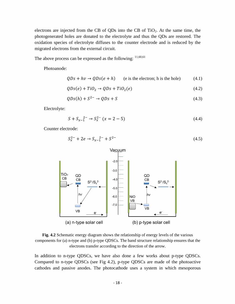
- 18 -
electrons are injected from the CB of QDs into the CB of TiO2. At the same time, the
photogenerated holes are donated to the electrolyte and thus the QDs are restored. The
oxidation species of electrolyte diffuses to the counter electrode and is reduced by the
migrated electrons from the external circuit.
The above process can be expressed as the following: 11,60,61
Photoanode:
( ) (e is the electron; h is the hole) (4.1)
( ) ( ) (4.2)
( ) (4.3)
Electrolyte:
( ) (4.4)
Counter electrode:
(4.5)
Fig. 4.2 Schematic energy diagram shows the relationship of energy levels of the various
components for (a) n-type and (b) p-type QDSCs. The band structure relationship ensures that the
electrons transfer according to the direction of the arrow.
In addition to n-type QDSCs, we have also done a few works about p-type QDSCs.
Compared to n-type QDSCs (see Fig 4.2), p-type QDSCs are made of the photoactive
cathodes and passive anodes. The photocathode uses a system in which mesoporous
- 19 -
nanocrystalline nickel oxide (NiO) is coated on the FTO and then QDs are deposited on
it.62-64
Counter electrode is still same to that of n-type cells. The target of this cell is to
develop the photocathodes and offer a choice to fabricate the tandem solar cells which
use n-type semiconductor as photoanode and p-type as photocathode in order to improve
further the energy conversion efficiency of QDSCs.65-67
In p-type QDSCs, photoexcited electronds in the QDs are expected to transfer to the
electrolyte and then to the counter electrode by the diffusion of electrolyte. The oxidized
QDs are reduced by the electron from the VB of NiO. Through the external circuit,
electron is migrated back to NiO.
4.1.2 Basic components
A. Mesoporous nanocrystalline semiconductor
In QDSCs, the mesoporous semiconductor, normally a semiconductor oxide coated on
conducting glass, plays a role of supporting the sensitizers (organic dye or QDs) and
transporting the electrons. It should at least meet the following conditions:68,69
a) A sufficiently large surface area for absorbing a large amount of sensitizers.
b) The energy levels of semiconductor oxide, sensitizer and electrolyte should match
each other, so that electron transfer is possible in thermodynamic.
c) To ensure that electrons can efficiently inject into the CB of semiconductor oxide.
d) Electron in the semiconductor has a faster transfer speeds and thus reduce the
electron recombination with electrolyte.
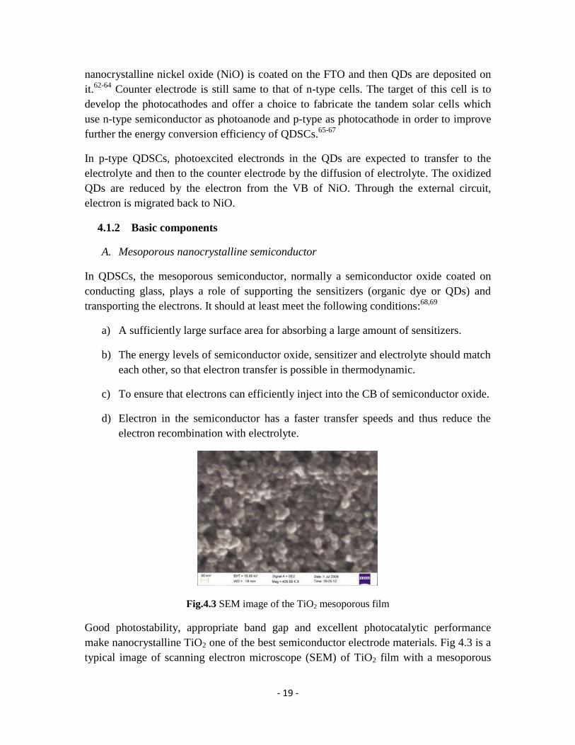
Fig.4.3 SEM image of the TiO2 mesoporous film
Good photostability, appropriate band gap and excellent photocatalytic performance
make nanocrystalline TiO2 one of the best semiconductor electrode materials. Fig 4.3 is a
typical image of scanning electron microscope (SEM) of TiO2 film with a mesoporous

- 20 -
structure. Furthermore the photoconversion efficiency can be developed by using TiO2
nanotubes as the working electrode due to the fast rate of electron transport in the TiO2
nanotube. In addition, ZnO with a wide bandgap similar to TiO2 is also a good choice as
electrode materials.70,71
B. QDs
In the past ten year, many kinds of QDs were used in QDSCs, such as CdS,72
CdSe,73
CdTe,74
PbS,10
Sb2S3,14
Bi2S3,75
Ag2S76
and InP.77
In QDSCs system, QDs as sensitizers
play a role of energy collection like the light-harvesting antenna.10
Their performances
have a direct impact on the photoelectric conversion of QDSCs and thus QDs are one of
the most important parts that ensure the efficient work of QDSCs. The size dependence
of absorption spectrum makes QDs to efficiently harvest light in the visible area. Due to
the tunable bandgap, the CBs of QDs can match the CB of TiO2 and thereby ensure
effective electron transfer from QDs to TiO2. And QDs give a high theoretical efficiency
for QDSCs because of their multiple-exciton effect. Moreover QDs have a better
photochemical stability compared to organic dye.11
C. Electrolyte
The electrolyte generally contains a redox couple including a reduction and an oxidation
species, and is an important part of QDSCs to ensure the cells work normally. When the
excited electrons are injected into the CB of TiO2 from QDs, QDs are oxidized. In order
to make photoelectric conversion occur continuously, the QDs should be regenerated by
the redox couple in the electrolyte. I-/I3
- of redox couple is mostly used in DSCs.
4 It may
quickly restore the oxidized dye and thus effectively inhibit the charge recombination on
the electrode surface. Unfortunately its corrosion leads to a quick decomposition of QDs,
thereby causing the much decrease of photovoltaic efficiency and lifetime.78,79
In order to
replace the iodide electrolyte, the inorganic redox couple polysulfide (S2-
/Sx2-
) is mostly
employed in QDSCs. It is not corrosive to QDs and can give stable photovoltaic
performance and increase the lifetime of QDSCs.9,69,80
However QDSCs using S2-
/Sx2-
as
electrolyte show a lower open-circuit voltage (Voc) and fill factor (FF) than that of I-/I3
-
electrolyte.81
These problems may be the result of its higher redox potential (-0.45 V vs
NHE) compared to I-/I3
- (+0.35 V vs NHE) and low activity with counter electrode, such
as Pt.82,83
Grätzel group developed cobalt redox couple (Co2+
/Co3+
) as electrolyte for QDSCs. 3,84,85
For CdSe based QDSCs, it can ensure that the solar cells are stabile and short-circuit
current (Jsc) decreased less than 20% after 6 weeks. But the complexity of their synthesis
limits their application in QDSCs.

- 21 -
So the development of a stable and commercially available electrolyte is an effective way
to improve the performance of QDSCs. We have developed two pure organic electrolytes
for QDSCs, see more discussions in section 5.3.
D. Counter electrode
The role of the counter electrode is to catalyze the reduction of redox couple in the
electrolyte. Because the catalytic reduction of Platinum (Pt) to iodine electrolyte is
relatively strong, the common electrode is prepared by depositing a layer of Pt on FTO
conductive glass. However, Pt produces poor catalytic activity for the polysulfide
electrolyte, resulting in low FF.83
So researchers have exerted to find an ideal alternative
to replace Pt. Some materials of counter electrode (Au, CoS, Cu2S and porous carbon)
have been reported for Pt-free QDSCs and given better performances.11,86-88
4.2 Synthesis of colloidal QDs and QRs
In 1993, Bawendi et al. first proposed the hot-injection method to chemically synthesize
colloidal CdSe QDs through the method of the pyrolysis of organometallic reagents by
injecting the precursor solution into a hot coordinating solvent.89
In this thesis, all of II-
VI colloidal semiconductor nanocrystals (QDs and QRs) are synthesized according to this
hot-injection process with a few modifications.41,90
And all the prepared nanocrystals are
hydrophobic. All reactions are managed under N2 or Ar atmosphere using standard
Schlenk techniques.
4.2.1 Synthesis of QDs
QDs used in the thesis work mainly include single-core QDs (CdS, CdSe and ZnSe) and
core/shell QDs (CdS/ZnSe and ZnSe/CdS). ZnSe/CdS QDs are made as an example to
introduce the synthesis procedure. Others QDs are synthesized by a similar procedure
with a few differences in growth temperature, solvent, organic ligands and reaction time
et al. (see the detail of procedure in the attached Papers).

- 22 -
Fig.4.4 Schematic reaction device (left) of colloidal QDs by hot-inject method and reaction
pathway (right) of colloidal ZnSe QDs.
Type-II ZnSe/CdS core/shell QDs were synthesized by a two steps process, which
consists of growth and purification of ZnSe seed QDs as a core, followed by growth of a
CdS shell.
Fig 4.5 TEM image of ZnSe/CdS QDs
Synthesis of ZnSe core: To form pure crystals of high quality, the hot-injection process
was adopted to synthesize ZnSe QDs, i.e., heating reactant precursor (Zn-precursor) to a
quite high temperature and then injecting another precursor (Se-precursor) into it, as
shown in Fig. 4.4. The typical synthesis process is as following.
Zinc oxide and stearic acid were dissolved in non-coordinating solvent octadecene (ODE)
by heating the reagents to 280 ºC in the three-necked flask under N2 flow, while keeping
stir. After the mixture was totally dissolved as a clear solution, a selenium stock solution
was injected quickly into the reaction flask, prepared by dissolving selenium powder in
trioctylphosphine (TOP). Keep the temperature at 270–280 ºC during the nanocrystal

- 23 -
growth. The reaction was terminated after 10 min by removing the heating mantle. Some
hexane was added when the mixture was cooled to 60 ºC. The residual reagent was
removed by washing the reaction mixture with methanol three times. The average
diameter of the resulting ZnSe cores is about 4.5 nm.
Deposition of CdS shell: The CdS shell growth was accomplished by the technique of
successive ion layer adsorption reactions (SILAR),43
which is used by alternately
injecting cadmium and sulfur precursors into the solution with prepared CdS core QDs in
1-octadecanamine (ODA) and ODE at 190~210 ºC. To prevent the formation of CdSe
interlayers between the ZnSe core and CdS shells, the sulfur precursor was injected first.
The cadmium and sulfur precursors were prepared by dissolving CdO in oleic acid (OA)
and ODE and dissolving sulfur in ODE, respectively. During SILAR procedure, sulfur
and cadmium precursors were injected in sequences during 10 min, respectively.
Repeated the procedure two or three times to give two or three layers of CdS shell and
the deposition was ended when QDs reached the targeted size. And then the reaction
mixture was kept in 190 ºC for 30 min and carried out the washing process in order to
obtain the desired ZnSe/CdS core/shell QDs (TEM image shown in Fig. 4.5).
4.2.2 Synthesis of QRs
Synthesis of CdS/CdSe QRs: Firstly CdS QDs as a seed should be synthesized in
advance. The reaction process was similar to that of ZnSe. Subsequently, in the growth of
CdSe shell of rods on the CdS seed, the SILAR method was used by alternately injecting
cadmium and selenium precursors into the solution with CdS core QDs in OA and ODE
at 190 ~210 ºC. The cadmium and selenium precursors were prepared by dissolving CdO
in oleic acid and ODE and dissolving selenium in TOP and ODE, respectively. In SILAR
procedure, selenium and cadmium precursors were injected in sequences during 5~10
min, respectively, and then the procedure was repeated one or two times. After these, the
reaction mixture was kept in 190 ºC for 30 min, followed the washing process in order to
obtain the desired quantum rods, whose TEM image is shown in Fig. 3.6.
4.3 Fabrication and assembly of QDSCs
4.3.1 Fabrication of TiO2 and NiO photoelectrode
The typical TiO2 electrode is fabricated according to the procedure reported in the
literature61
with few modifications. The TiO2 film (about 12 mm thick) is made by
doctor-blading nanocrystalline TiO2 colloidal solution onto a cleaned conducting glass
surface with a layer of Fluoride-doped tin oxide (FTO), following the sintering at 450 ºC
for 30 min. After the sintering, a final treatment is carried out, which the sintered TiO2
film is immersed in 40 mM TiCl4 aqueous solution at 70 ºC for half an hour, followed by
- 24 -
washing the film with deionized water and re-sintering at 450 ºC for 30 min. A uniform
dispersion of TiO2 colloidal solution is prepared by mixing and grinding a mixture with
commercial P25 TiO2, acetylacetone, deionized water and a kind of surfactant of Triton
X-100.
NiO electrode was prepared according to the following procedure.64
The precursor
solution of NiO was obtained by dissolving NiCl2 and co-polymer F108 into Milli-Q
water and ethanol. The film is made by doctor blading the precursor solution onto a
cleaned FTO glass, followed by sintering at 450 ºC for 30 min to remove remaining
organic chemicals.
4.3.2 QDs deposition on photoelectrode
Usually there are two common methods to deposit QDs on photoelectrode.
A. In situ growth of QDs on photoelectrode
This method is to directly grow QDs onto the electrode according to the chemical
bath deposition (CBD) process of successive ionic layer adsorption and reaction
(SILAR) in alcohol solutions by the ionic chemical reaction.11,85
For example of
CdS QDs deposition on TiO2 electrode, the TiO2 film is immersed into a
Cd(NO3)2 methanol solution for several min, washed with methanol, then
immersed for another several min into a Na2S methanol solution and washed
again with methanol. The two-step immersing procedure is labeled as one CBD
cycle. The deposited amount of CdS QDs can increase though repeating the CBD
cycles, accompanied by QD size increase.
Compared to colloidal QDs, direct growth on TiO2 facilitates the electron
injection into TiO2, and no organic ligand on its surface is in favor for polysulfide
electrolyte to penetrate into the pores of electrode and thus increase the interaction
between QDs and electrolyte. Now this method is mostly utilized and more than
4 % of conversion efficiency has been obtained.11
B. Deposition by a bifunctional linker molecule
This method is to connect pre-synthesized colloidal QDs with photoelectrode
material by a bifunctional linker molecule.60,61
This molecule (HOOC-R-SH)
consists of a carboxylate and thiol functional group at its both terminals. The
carboxylate group is used to bind to electrode and thiol group is attached to QDs.
We always utilize mercaptopropionic acid (MPA, HOOC-C2H4-SH) as linker.
The typical process is that the TiO2 electrodes are immersed in a 1 M MPA
acetonitrile solution for 12 h, and then transferred to the QDs toluene solution for
1~2 days, as schematic shown in Fig. 4.6.

- 25 -
Compared with the direct growth QDs on photoelectrode which has the difficulty
of controlling the size distribution of QDs on TiO2, colloidal QDs deposition can
provide uniform and precise morphological characteristics in shape and size.
Sometimes these two methods are used together to prepare the QDs-coated
photoelectrode. For example, colloidal CdSe QDs are deposited on TiO2 by linker,
followed by deposition of directly grown CdSe using CBD method. The
assembled solar cells show a better conversion efficiency.91
Fig 4.6 Schematic process of connection between TiO2 and QDs with a bifunctional molecule
MPA as linker. The carboxylate group of MPA is bound to TiO2 and its thiol group is attached to
QDs.
In the fabrication of QDSCs, a layer of ZnS is always deposited on QDs-coated
photoelectrode by CBD method.92
With ZnS coating, the conversion efficiency of
QDSCs can be increased substantially. Firstly, ZnS can passivate the surface of QDs and
thus inhibit the carrier loss due to surface trapping of QDs. Secondly, because the wide
bandgap of ZnS makes its CB higher than the CB of many QDs, ZnS can efficiently
suppress the recombination of photoexcited electron at the interface between
photoelectrode and electrolyte. Moreover, ZnS can increase the chemical stability of
QDSCs.
4.3.3 Fabrication of counter electrode
The counter electrode loading a catalytic amount of Pt is prepared as followed.93
Firstly
the chemical of H2PtCl6 is dissolved into isopropyl alcohol to prepare a solution (3% by
mass). And sequentially drop a little amount of solution on the surface of FTO glass with
a predrilled hole, followed by rolling with a glass rod on the surface to get a uniform
coating. After drying, the electrode is sintered at 400 ºC for 20~30 min, leading to the
thermal decomposition of H2PtCl6 into Pt.
4.3.4 Assembly of QDSCs

- 26 -
Finally, QDs-coated photoelectrode as a working electrode and Pt-coated FTO glass as a
counter electrode are assembled to fabricate QDSCs with 60 μm Surlyn gasket as the
sealing thermoplastic material. Electrolyte is introduced to fill the empty space between
the two electrodes through a hole on the counter electrode, and the hole is sealed with a
Surlyn sheet and a thin cover glass by heating. A black mask (8 mm × 8 mm) is used in
the subsequent photovoltaic studies.
4.4 Characterization of QDs and QDSCs
4.4.1 Optical characterization of QDs
A. UV-Vis Absorption Spectroscopy
Ultraviolet-visible (UV-vis) absorption spectroscopy is used to characterize the light-
harvesting capability of the QDs in the solution or on the film. We can obtain the
information about the size and bandgap of QDs from UV-vis spectrum due to size-
dependent effect as discussed in section 3.2.1.
UV-Vis abortion was recorded by using a Lambda 750 UV-Vis spectrometer. In a typical
experiment, the absorbance of the substance is recorded as a function of wavelength of
light. The analysis can be carried out either in solution with the same solvent as the blank
or on the film with transparent bare film as the blank.
B. Fluorescence spectroscopy
Fluorescence spectroscopy is complementary to UV-Vis spectroscopy. Fluorescence is a
form of luminescence, which is the emission of light from a substance. Fluorescence
occurs when the substance absorbs a photon and is excited from its ground state to the
excited state, then drops down to one of the various vibrational levels of the ground state
again. In the process, thermal losses occur in the most cases, leading to a longer
wavelength of emission than the wavelength of absorption of light.
The fluorescence spectra were measured by using a Cary Eclipse fluorescence
spectrophotometer. In a typical experiment, the fluorescent was measured using a
monochromator, holding the excitation light at a certain wavelength where is typically
the strongest absorption in the UV-Vis spectroscopy.
4.4.2 Characterization of photovoltaic performance of QDSCs
A. Photon to current conversion efficiency (IPCE and APCE)
Incident photon to current conversion efficiency (IPCE) is one of the standard
characterization techniques used for DSCs and QDSCs, which describes how efficiently

- 27 -
the incoming incident photons are converted to electrons. “The IPCE value corresponds
to the photocurrent density produced in the external circuit under monchromatic
illumination of the cell divided by the photon flux that strikes the cell”.94
It can be
calculated according to the equation 4.6, where h is the Plank’s constant, c is the speed of
light, e is the elementary charge, JPH is the short circuit current density generated by the
cell under the illumination of the monochromatic light, λ is the wavelength of the
incident light, and Pin is the light intensity of the incident light, respectively.
( ) ( )
( )
( )
( )
( )
( ) (4.6)
IPCE measurements presented in this thesis were mostly performed using a
monochromatic light from a system containing a Xenon lamp, a monchromator, and
appropriate filters. The system was calibrated by using a reference silicon solar cell.
IPCE measurements are carried out by measuring the short-circuit current every 10 nm in
the range of 400~900 nm under the short-circuit mode. Thereby IPCE spectrum can be
obtained through equation 4.6 (see Fig. 4.7).
Fig 4.7 Typical IPCE spectrum of QDSCs is obtained by measuring the short-circuit current
every 10 nm in the normal range of 400~900 nm under the short-circuit mode.
By taking into account the absorbance, the absorbed photon to current efficiency (APCE)
can be calculated from the follow equation:
( ) ( )
( ) (4.7)
where Abs(λ) is the absorbance of the photoanode at λ.
The APCE describes how efficiently the absorbed photons are converted to electrons.
When considering the differences in the absorption capability of QDs on TiO2, it seems
that it is better to use the APCE values in the comparison of electron-injection
efficiencies.

- 28 -
B. Current density-voltage characteristics (J-V)
Current density-voltage (J-V) measurement under illumination is another conventional
measurement to quantitatively evaluate the efficiencies of DSCs and QDSCs. The
photovoltaic performance of solar cells can be illustrated by a J-V curve (see Fig. 4.8).
The efficiency of a solar cell, η, is given by equation 4.8
(4.8)
where Pmax is the maximum obtainable power of the cell, Pin is the input of the
illumination intensity, Jmax is the maximum current density of the cell, and Vmax is the
maximum voltage of the cell, respectively.
To order to describe the efficiency in terms of the short-circuit current (Jsc) and open-
circuit voltage (Voc), fill factor (FF) is introduced, which is the ratio of Pmax to the product
of the Jsc and Voc according to equation 4.9
(4.9)
Thus, the efficiency can be written by equation 4.10
(4.10)
Under illumination, the current-voltage was monitored by using a Keithley source/meter
from zero load (short-circuit condition) to infinite load (open-circuit condition). The
illumination was provided by a sun simulator with a spectrum very similar the AM 1.5
and an intensity of 1000 W/m2 which is also referred to as 1 sun.
Fig 4.8 Typical J-V curve of QDSCs
- 29 -
Chapter 5
Results and Conclusions
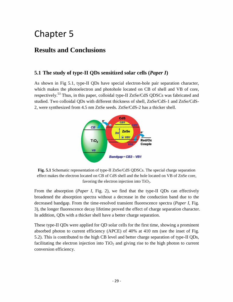
5.1 The study of type-II QDs sensitized solar cells (Paper I)
As shown in Fig 5.1, type-II QDs have special electron-hole pair separation character,
which makes the photoelectron and photohole located on CB of shell and VB of core,
respectively.53
Thus, in this paper, colloidal type-II ZnSe/CdS QDSCs was fabricated and
studied. Two colloidal QDs with different thickness of shell, ZnSe/CdS-1 and ZnSe/CdS-
2, were synthesized from 4.5 nm ZnSe seeds. ZnSe/CdS-2 has a thicker shell.
Fig. 5.1 Schematic representation of type-II ZnSe/CdS QDSCs. The special charge separation
effect makes the electron located on CB of CdS shell and the hole located on VB of ZnSe core,
favoring the electron injection into TiO2.
From the absorption (Paper I, Fig. 2), we find that the type-II QDs can effectively
broadened the absorption spectra without a decrease in the conduction band due to the
decreased bandgap. From the time-resolved transient fluorescence spectra (Paper I, Fig.
3), the longer fluorescence decay lifetime proved the effect of charge separation character.
In addition, QDs with a thicker shell have a better charge separation.
These type-II QDs were applied for QD solar cells for the first time, showing a prominent
absorbed photon to current efficiency (APCE) of 40% at 410 nm (see the inset of Fig.
5.2). This is contributed to the high CB level and better charge separation of type-II QDs,
facilitating the electron injection into TiO2 and giving rise to the high photon to current
conversion efficiency.

- 30 -
Fig 5.2 The IPCE spectra of QDSCs based on ZnSe/CdS-1 and ZnSe/CdS-2 QDs. The inset is the
absorption spectra of them adsorbed on the TiO2 film.
5.2 The study of quantum rods-sensitized solar cells (Paper II)
Compared to QDs with the strong intrinsic quantum confinement effect for the carriers in
three-dimensional space, QRs may bring the opportunity to increase the efficiency of
colloidal nanocrystals-sensitized solar cells by improving the electron injection efficiency
due to their two-dimensional confinement which facilitates the carriers transport in QRs,
as shown in Fig. 5.3. With this mind, we synthesized a new kind of colloidal CdSe
nanorods with CdS as seed, and applied them for quantum rod-sensitized solar cells
(QRSCs) for the first time.
Fig 5.3 Schematic drawing of the electron transfer process for QDs and QRs. QRs with two-
dimensional confinement would facilitate the carriers transport, thus improving the electron
injection efficiency to TiO2.
Calculated from the fluorescence lifetimes on glass and TiO2 substrate by the time-
resolved transient fluorescence spectra (Paper II, Fig. 4), the electron-injection constant
of QRs on TiO2 is larger than that of CdSe QDs, indicating that the electron injection rate
of the QRs is faster than for the QDs.
- 31 -
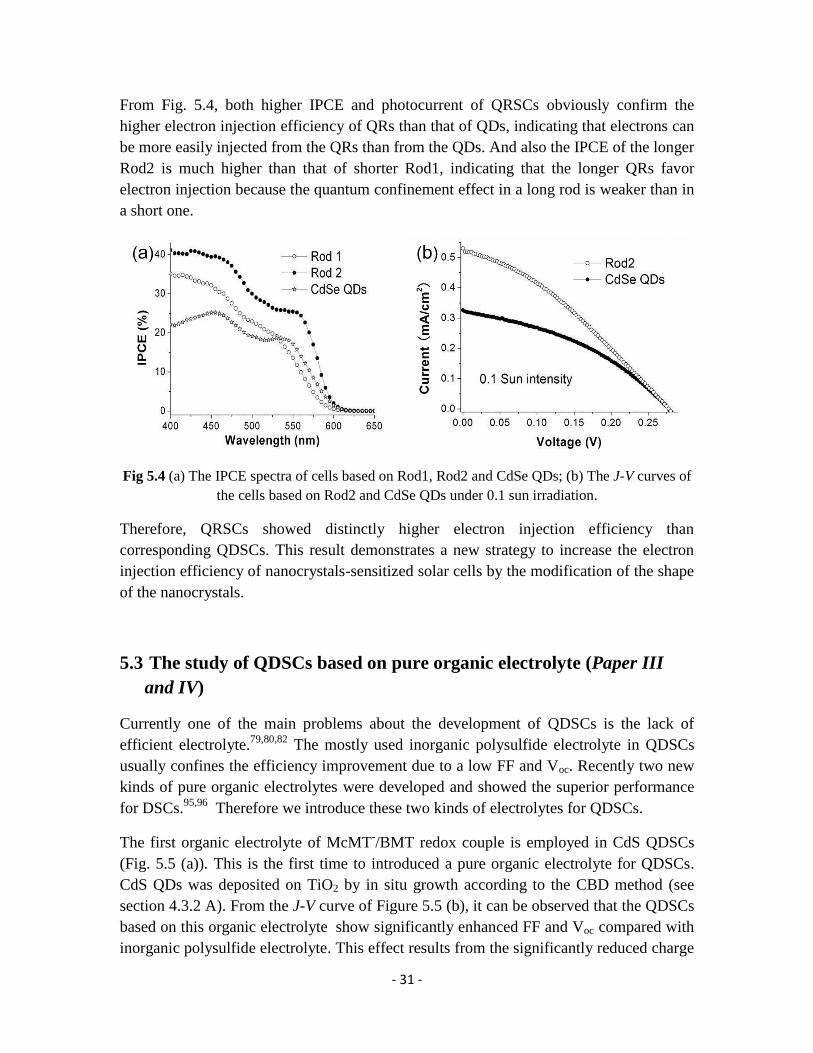
From Fig. 5.4, both higher IPCE and photocurrent of QRSCs obviously confirm the
higher electron injection efficiency of QRs than that of QDs, indicating that electrons can
be more easily injected from the QRs than from the QDs. And also the IPCE of the longer
Rod2 is much higher than that of shorter Rod1, indicating that the longer QRs favor
electron injection because the quantum confinement effect in a long rod is weaker than in
a short one.
Fig 5.4 (a) The IPCE spectra of cells based on Rod1, Rod2 and CdSe QDs; (b) The J-V curves of
the cells based on Rod2 and CdSe QDs under 0.1 sun irradiation.
Therefore, QRSCs showed distinctly higher electron injection efficiency than
corresponding QDSCs. This result demonstrates a new strategy to increase the electron
injection efficiency of nanocrystals-sensitized solar cells by the modification of the shape
of the nanocrystals.
5.3 The study of QDSCs based on pure organic electrolyte (Paper III
and IV)
Currently one of the main problems about the development of QDSCs is the lack of
efficient electrolyte.79,80,82
The mostly used inorganic polysulfide electrolyte in QDSCs
usually confines the efficiency improvement due to a low FF and Voc. Recently two new
kinds of pure organic electrolytes were developed and showed the superior performance
for DSCs.95,96
Therefore we introduce these two kinds of electrolytes for QDSCs.
The first organic electrolyte of McMT-/BMT redox couple is employed in CdS QDSCs
(Fig. 5.5 (a)). This is the first time to introduced a pure organic electrolyte for QDSCs.
CdS QDs was deposited on TiO2 by in situ growth according to the CBD method (see
section 4.3.2 A). From the J-V curve of Figure 5.5 (b), it can be observed that the QDSCs
based on this organic electrolyte show significantly enhanced FF and Voc compared with
inorganic polysulfide electrolyte. This effect results from the significantly reduced charge

- 32 -
recombination in McMT-/BMT based QDSCs, confirmed by dark current and impedance
measurement (Paper IV, Fig. 1(b) and Fig. 3). Therefore the overall conversion efficiency
of QDSCs based on the new organic electrolyte was doubled to that of inorganic
electrolyte.
Fig 5.5 (a) Schematic representation of CdS QDSCs based on organic electrolyte; (b) The J-V
curves of CdS QDSCs based on the McMT-/BMT electrolyte (OS) and inorganic polysulfide
electrolyte (IS) under one sun irradiation.
The second organic electrolyte is a sulfide redox couple of TMTU and TMTU-TFO
shown in Fig. 5.6. This kind of electrolyte combined with colloidal type-II QDs is
introduced for QDSCs. Two type-II core/shell ZnSe/CdS and CdS/ZnS QDs were
synthesized.
Fig 5.6 Schematic molecular structure of TMTU and TMTU-TFO electrolyte (OS2)
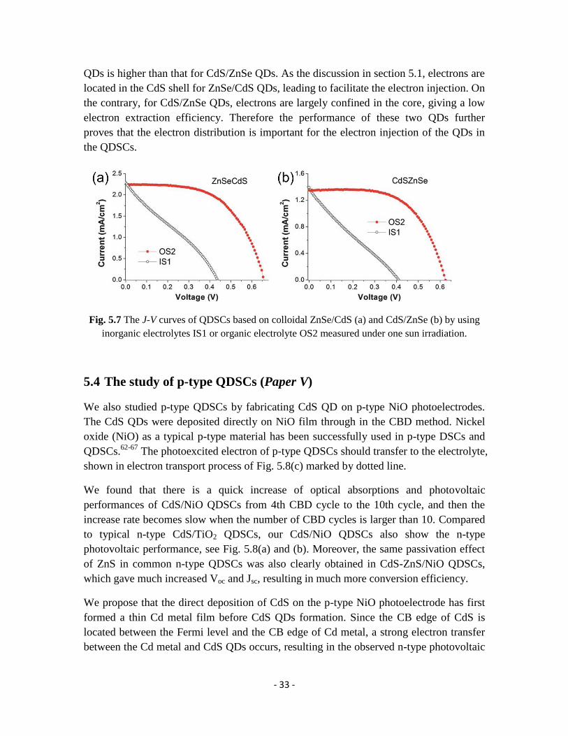
As shown in Fig. 5.7, the FF of these cells based on this type of organic electrolyte was
significantly improved due to the reduced impedance (Paper III, Fig. 6) between the
electrolyte and counter electrode. It is possible to substantially increase the photovoltage
and to reach an efficiency three times higher than that of a commonly used inorganic
redox couple.
Furthermore, Jsc of the QDSC based on the ZnSe/CdS QDs is obviously higher than that
of CdS/ZnSe. Similarly, IPCE of ZnSe/CdS QDSCs is also higher (Paper III, Fig. 3).
Since these two QDs adsorbed on TiO2 films exhibit a similar absorption spectrum
(Paper III, Fig. 4), it can be concluded that the electron injection efficiency of ZnSe/CdS
- 33 -
QDs is higher than that for CdS/ZnSe QDs. As the discussion in section 5.1, electrons are
located in the CdS shell for ZnSe/CdS QDs, leading to facilitate the electron injection. On
the contrary, for CdS/ZnSe QDs, electrons are largely confined in the core, giving a low
electron extraction efficiency. Therefore the performance of these two QDs further
proves that the electron distribution is important for the electron injection of the QDs in
the QDSCs.
Fig. 5.7 The J-V curves of QDSCs based on colloidal ZnSe/CdS (a) and CdS/ZnSe (b) by using
inorganic electrolytes IS1 or organic electrolyte OS2 measured under one sun irradiation.
5.4 The study of p-type QDSCs (Paper V)
We also studied p-type QDSCs by fabricating CdS QD on p-type NiO photoelectrodes.
The CdS QDs were deposited directly on NiO film through in the CBD method. Nickel
oxide (NiO) as a typical p-type material has been successfully used in p-type DSCs and
QDSCs.62-67
The photoexcited electron of p-type QDSCs should transfer to the electrolyte,
shown in electron transport process of Fig. 5.8(c) marked by dotted line.
We found that there is a quick increase of optical absorptions and photovoltaic
performances of CdS/NiO QDSCs from 4th CBD cycle to the 10th cycle, and then the
increase rate becomes slow when the number of CBD cycles is larger than 10. Compared
to typical n-type CdS/TiO2 QDSCs, our CdS/NiO QDSCs also show the n-type
photovoltaic performance, see Fig. 5.8(a) and (b). Moreover, the same passivation effect
of ZnS in common n-type QDSCs was also clearly obtained in CdS-ZnS/NiO QDSCs,
which gave much increased Voc and Jsc, resulting in much more conversion efficiency.
We propose that the direct deposition of CdS on the p-type NiO photoelectrode has first
formed a thin Cd metal film before CdS QDs formation. Since the CB edge of CdS is
located between the Fermi level and the CB edge of Cd metal, a strong electron transfer
between the Cd metal and CdS QDs occurs, resulting in the observed n-type photovoltaic

- 34 -
performance of our QDSCs. The electron transfer process is shown in Fig. 5.8(c) marked
by solid line.
Fig. 5.8 (a) J–V curves of CdS/NiO QDSCs and (b) J–V characteristics of CdS/TiO2 QDSCs with
different CDB cycles measured under one sun. (c) Schematic energy diagrams of CdS/NiO
QDSCs; The red arrows with dotted line for the electron transfer of typical p-type QDSCs, the
black arrows with solid line for the proposed n-type electron transfer.
(c)

- 35 -
Chapter 6
Future outlook
Although QDSCs possess an excellent theoretically potential and have a fast
development in recent years, the overall efficiency of QDSCs is still far less than the
requirement for large scale applications. Many critical challenges need to be met in the
future, most important of all is to increase electron transport rate and light harvesting
ability, decrease charge recombination, low toxicity, extend durability. We can improve
the performance of QDSCs from the following four aspects:
TiO2 photoelectrode. Compared to the common photoelectrode with spherical
nanoparticle TiO2, TiO2 nanotube, nanorod and nanowire were confirmed to be an
efficient structures to improve electron transport and thus decrease the charge
recombination between TiO2 and QDs or electrolyte.61
And also this strategy is helpful to
increase the deposition amount of QDs on TiO2 electrode due to large surface areas of
these nanostructures, thereby increasing the light harvesting efficiency. In addition, other
materials with similar structures, such as ZnO70
and carbon97
, can be employed.
QDs. As extensively discussed in the thesis, the spatial electron and hole separation of
type-II QDs and the reduction of the carrier confinement dimensions of QRs can enhance
electron injection. Further research along this line should be made in order to find the
nanocrystals with broader adsorption spectrum. For the consideration of toxicity, low
toxic QDs, such as InP, Ag2S, Sb2S3 and CuInS, should be employed in QDSCs. In
addition, we can develop more effective passivation materials, like ZnS, to suppress the
recombination between photoelectrode and electrolyte and increase the chemical stability
of QDSCs.
Electrolyte. Organic electrolyte is a strategy to develop the performance of QDSCs by
reducing the charge recombination between the electrolyte and counter electrode. This
electrolyte should be noncorrosive for QDs. Additionally, using low-volatile solvent,
ionic liquids or solid electrolyte is the good choice to increase the durability of solar cells.
Counter electrode. Although many new materials for the counter electrode have been
used in QDSCs and also can give an improved performance, their fill factors (FF) are still
lower than the level of DSCs. Thus, much effort should be taken to develop more
efficient counter electrode for QDSCs.

- 36 -
Therefore, we believe that QDSCs will have a clear potential to overtake the efficiency of
all other kinds of solar cells and contribute to the world energy market.

- 37 -
Acknowledgements
I would like to express my sincere gratitude to:
Associate Prof. Ying Fu, my supervisor, for accepting me as a Ph.D student, for
providing the great working condition, and for being so patient and encouraging during
the years.
Dr. Zhijun Ning, my excellent colleague and friend, for sharing the knowledge,
collaborations and support especially during the beginning of my Ph.D. I learned a lot
from you. It’s great to work with you.
Prof. Hans Ågren, Prof. Licheng Sun for the help, support and nice collaboration.
Prof. Yi Luo for the warm-hearted helps.
Haining, Haiyan, Lin and Peter for encouraging discussion and nice collaboration.
All the members of Licheng Sun’s group for being so friendly and helpful, in particular
Haining and Lin for nice collaboration.
Marlene and Nina for all helps with administrative things.
Zhihui, Shangjun, Xifeng, Li and Staffan for providing positive and enjoyable working
environment throughout the group.
Xifeng and Lijun for sharing the office.
All former and present co-workers at the department of theoretical chemistry & biology
for spreading the nice atmosphere.
My friends and family for always being there.
My wife Lin for every single day.

- 38 -
References
(1) Chapin, D. M.; Fuller, C. S.; Pearson, G. L. J. Appl. Phys. 1954, 25, 676-677.
(2) O'Regan, B.; Grätzel, M. Nature 1991, 353, 737-740.
(3) Yella, A.; Lee, H.-W.; Tsao, H. N.; Yi, C.; Chandiran, A. K.; Nazeeruddin, M. K.;
Diau, E. W.-G.; Yeh, C.-Y.; Zakeeruddin, S. M.; Grätzel, M. Science 2011, 334, 629-634.
(4) Hagfeldt, A.; Boschloo, G.; Sun, L.; Kloo, L.; Pettersson, H. Chem. Rev. 2010, 110,
6595-6663.
(5) Bruchez, M., Jr.; Moronne, M.; Gin, P.; Weiss, S.; Alivisatos, A. P. Science 1998,
281, 2013-2016.
(6) Medintz, I.; Uyeda, H.; Goldman, E.; Mattoussi, H. Nat. Mater. 2005, 4, 435-481.
(7) Anikeeva, P. O.; Halpert, J. E.; Bawendi, M. G.; Bulovic, V. Nano Lett. 2009, 9,
2532-2536.
(8) Huynh, W. U.; Dittmer, J. J.; Alivisatos, A. P. Science 2002, 295, 2425-2427.
(9) Mora-Sero, I.; Gimenez, S.; Fabregat-Santiago, F.; Gomez, R.; Shen, Q.; Toyoda, T.;
Bisquert, J. Acc. Chem. Res. 2009, 42, 1848-1857.
(10) Lee, H.; Leventis, H. C.; Moon, S.-J.; Chen, P.; Ito, S.; Haque, S. A.; Torres, T.;
Nueesch, F.; Geiger, T.; Zakeeruddin, S. M.; Grätzel, M.; Nazeeruddin, M. K. Adv. Funct.
Mater. 2009, 19, 2735-2742.
(11) Lee, Y.-L.; Lo, Y.-S. Adv. Funct. Mater. 2009, 19, 604-609.
(12) Yu, X.-Y.; Liao, J.-Y.; Qiu, K.-Q.; Kuang, D.-B.; Su, C.-Y. ACS Nano 2011, 5,
9494-9500.
(13) Randy, J. E.; Matthew, C. B.; Justin, C. J.; Pingrong, Y.; Olga, I. M.; Arthur, J. N.;
Andrew, S.; Alexander, L. E. Nano Lett. 2005, 5, 865-871.
(14) Chang, J. A.; Rhee, J. H.; Im, S. H.; Lee, Y. H.; Kim, H.-j.; Seok, S. I.;
Nazeeruddin, M. K.; Grätzel, M. Nano Lett. 2010, 10, 2609-2612.
(15) Zhang, Q.; Guo, X.; Huang, X.; Huang, S.; Li, D.; Luo, Y.; Shen, Q.; Toyoda, T.;
Meng, Q. Phys. Chem. Chem. Phys. 2011, 13, 4659-4667.
(16) Salerno, E. AWEA Director of Industry and Data Analysis, as quoted in Shahan, Z,
2011.
(17) Grätzel, M. Nature 2001, 414, 338-344.
(18) Kopp, G.; Lean, J. L. Geophysical Research Letters 2011, 38.
(19) Wurfel, P. The Physics of Solar Cells; Wiley-VCH, 2005.
(20) Martin A, G. Physica E 2002, 14, 11-17.
(21) Nozik, A.; Beard, M.; Luther, J.; Law, M. Chem. Rev. 2010, 110, 6873-6890.
(22) Rossetti, R.; Brus, L. J. Phys. Chem. 1982, 86, 4470-4472.
(23) Yu, W. W.; Peng, X. Angew. Chem., Int. Ed. 2002, 41, 2368-2371.
(24) Qu, L.; Peng, X. J. Am. Chem. Soc. 2002, 124, 2049-2104.
(25) Lee, H. J.; Yum, J. H.; Leventis, H. C.; Zakeeruddin, S. M.; Haque, S. A.; Chen, P.;
Seok, S. I.; Gräzel, M.; Nazeeruddin, M. K. Journal of Physical Chemistry C 2008, 112,
11600-11608.
(26) Gao, M. Y.; Kirstein, S.; Mohwald, H.; Rogach, A. L.; Kornowski, A.; Eychmuller,
A.; Weller, H. J. Phys. Chem. B 1998, 102, 8360-8363.
- 39 -
(27) Gaponik, N.; Talapin, D. V.; Rogach, A. L.; Hoppe, K.; Shevchenko, E. V.;
Kornowski, A.; Eychmuller, A.; Weller, H. J. Phys. Chem. B 2002, 106, 7177-7185.
(28) Hines, M. A.; Guyot-Sionnest, P. J. Phys. Chem. B 1998, 102, 3655-3657.
(29) Xu, S.; Kumar, S.; Nann, T. J. Am. Chem. Soc. 2006, 128, 1054-1055.
(30) Battaglia, D.; Peng, X. G. Nano Lett. 2002, 2, 1027-1030.
(31) Xie, R.; Peng, X. Angew. Chem., Int. Ed. 2008, 47, 7677-7680.
(32) Tanaka, S.; Iwai, S.; Aoyagi, Y. Appl. Phys. Lett. 1996, 69, 4096-4098.
(33) Dasgupta, N. P.; Jung, H. J.; Trejo, O.; McDowell, M. T.; Hryciw, A.; Brongersma,
M.; Sinclair, R.; Prinz, F. B. Nano Lett. 2011, 11, 934-940.
(34) Murphy, J. E.; Beard, M. C.; Nozik, A. J. J. Phys. Chem. B 2006, 110, 25455-
25461.
(35) Niquet, Y. M.; Allan, G.; Delerue, C.; Lannoo, M. Appl. Phys. Lett. 2000, 77,
1182-1184.
(36) Littau, K. A.; Szajowski, P. J.; Muller, A. J.; Kortan, A. R.; Brus, L. E. J. Phys.
Chem. 1993, 97, 1224-1230.
(37) Dabbousi, B. O.; Rodriguez-Viejo, J.; Mikulec, F. V.; Heine, J. R.; Mattoussi, H.;
Ober, R.; Jensen, K. F.; Bawendi, M. G. J. Phys. Chem. B 1997, 101, 9463-9475.
(38) Xu, S.; Ziegler, J.; Nann, T. J. Mater. Chem. 2008, 18, 2653-2656.
(39) Xie, R.; Battaglia, D.; Peng, X. J. Am. Chem. Soc. 2007, 129, 15432-15433.
(40) Manna, L.; Scher, E. C.; Li, L.-S.; Alivisatos, A. P. J. Am. Chem. Soc. 2002, 124,
7136-7145.
(41) Xie, R.; Kolb, U.; Li, J.; Basché, T.; Mews, A. J. Am. Chem. Soc. 2005, 127, 7480-
7488.
(42) Kim, S.; Fisher, B.; Eisler, H.-J.; Bawendi, M. J. Am. Chem. Soc. 2003, 125,
11466-11467.
(43) Nemchinov, A.; Kirsanova, M.; Hewa-Kasakarage, N. N.; Zamkov, M. J. Phys.
Chem. C 2008, 112, 9301-9307.
(44) Zhong, X.; Han, M.; Dong, Z.; White, T. J.; Knoll, W. J. Am. Chem. Soc. 2003,
125, 8589-8594.
(45) Smith, A.; Nie, S. J. Am. Chem. Soc. 2011, 133, 24-26.
(46) Grabolle, M.; Spieles, M.; Lesnyak, V.; Gaponik, N.; Eychmuller, A.; Resch-
Genger, U. Anal. Chem. 2009, 81, 6285-6294.
(47) Yu, W. W.; Qu, L.; Guo, W.; Peng, X. Chem. Mater. 2003, 15, 2854-2860.
(48) Klimov, V. I. Annu. Rev. Phys. Chem. 2007, 58, 635-673.
(49) Klimov, V. I.; Mikhailovsky, A. A.; McBranch, D. W.; Leatherdale, C. A.;
Bawendi, M. G. Science 2000, 287, 1011-1013.
(50) Trinh, M. T.; Houtepen, A. J.; Schins, J. M.; Hanrath, T.; Piris, J.; Knulst, W.;
Goossens, A. P. L. M.; Siebbeles, L. D. A. Nano Lett. 2008, 8, 1713-1718.
(51) Fisher, B.; Caruge, J. M.; Zehnder, D.; Bawendi, M. Phys. Rev. Lett. 2005, 94,
087403.
(52) Sambur, J. B.; Novet, T.; Parkinson, B. A. Science 2010, 330, 63-66.
(53) de Mello Donega, C. Chem. Soc. Rev. 2011, 40, 1512-1546.
(54) Reiss, P.; Protiere, M.; Li, L. Small 2009, 5, 154-168.
(55) Smith, A. M.; Nie, S. Acc. Chem. Res. 2010, 43, 190-200.
(56) Kan, S.; Mokari, T.; Rothenberg, E.; Banin, U. Nat. Mater. 2003, 2, 155-158.
(57) Costi, R.; Saunders, A. E.; Banin, U. Angew. Chem., Int. Ed. 2010, 49, 4878-4897.

- 40 -
(58) Liang, H.-W.; Liu, S.; Yu, S.-H. Adv. Mater. 2010, 22, 3925-3937.
(59) Yang, Z.; Chen, C.-Y.; Roy, P.; Chang, H.-T. Chem. Commun. 2011, 47, 9561-
9632.
(60) Robel, I.; Subramanian, V.; Kuno, M.; Kamat, P. V. J. Am. Chem. Soc. 2006, 128,
2385-2393.
(61) Kongkanand, A.; Tvrdy, K.; Takechi, K.; Kuno, M.; Kamat, P. V. J. Am. Chem.
Soc. 2008, 130, 4007-4015.
(62) Wu, X.; Yeow, E. K. Chem. Commun. 2010, 46, 4390-4392.
(63) Qin, P.; Zhu, H.; Edvinsson, T.; Boschloo, G.; Hagfeldt, A.; Sun, L. J. Am. Chem.
Soc. 2008, 130, 8570-8571.
(64) Li, L.; Gibson, E. A.; Qin, P.; Boschloo, G.; Gorlov, M.; Hagfeldt, A.; Sun, L. Adv.
Mater. 2010, 22, 1759-1762.
(65) He, J.; Lindstrom, H.; Hagfeldt, A.; Lindquist, S. E. Sol. Energy Mater. Sol. Cells
2000, 62, 265-273.
(66) Morandeira, A.; Boschloo, G.; Hagfeldt, A.; Hammarström, L. J. Phys. Chem. B
2005, 109, 19403-19410.
(67) Nattestad, A.; Mozer, A. J.; Fischer, M. K.; Cheng, Y. B.; Mishra, A.; Bauerle, P.;
Bach, U. Nat. Mater. 2010, 9, 31-35.
(68) Shah, A.; Torres, P.; Tscharner, R.; Wyrsch, N.; Keppner, H. Science 1999, 285,
692-698.
(69) Kamat, P. V.; Tvrdy, K.; Baker, D. R.; Radich, J. G. Chem. Rev. 2010, 110, 6664-
6688.
(70) Kuo, K.-T.; Liu, D.-M.; Chen, S.-Y.; Lin, C.-C. J. Mater. Chem. 2009, 19, 6780-
6788.
(71) Greene, L. E.; Law, M.; Tan, D. H.; Montano, M.; Goldberger, J.; Somorjai, G.;
Yang, P. Nano Lett. 2005, 5, 1231-1236.
(72) Jia, H.; Xu, H.; Hu, Y.; Tang, Y.; Zhang, L. Electrochem. Commun. 2007, 9, 354-
360.
(73) Lévy-Clément, C.; Tena-Zaera, R.; Ryan, M. A.; Katty, A.; Hodes, G. Adv. Mater.
2005, 17, 1512-1515.
(74) Gao, X.-F.; Li, H.-B.; Sun, W.-T.; Chen, Q.; Tang, F.-Q.; Peng, L.-M. J. Phys.
Chem. C 2009, 113, 7531-7535.
(75) Peter, L. M.; Wijayantha, K. G. U.; Riley, D. J.; Waggett, J. P. J. Phys. Chem. B
2003, 107, 8378-8381.
(76) Tubtimtae, A.; Wu, K.-L.; Tung, H.-Y.; Lee, M.-W.; Wang, G. J. Electrochem.
Commun. 2010, 12, 1158-1160.
(77) Zaban, A.; Micic, O. I.; Gregg, B. A.; Nozik, A. J. Langmuir 1998, 14, 3153-3156.
(78) Schaller, R. D.; Klimov, V. I. Phys. Rev. Lett. 2004, 92, 186601.
(79) Sambur, J. B.; Parkinson, B. A. J. Am. Chem. Soc. 2010, 132, 2130-2131.
(80) Mora-Sero, I.; Bisquert, J. J. Phys. Chem. Lett. 2010, 1, 3046-3052.
(81) Lee, W.; Min, S. K.; Dhas, V.; Ogale, S. B.; Han, S. H. Electrochem. Commun.
2009, 11, 103-106.
(82) Tachibana, Y.; Akiyama, H. Y.; Ohtsuka, Y.; Torimoto, T.; Kuwabata, S. Chem.
Lett. 2007, 36, 88-89.
(83) Boschloo, G.; Hagfeldt, A. Acc. Chem. Res. 2009, 42, 1819-1826.
- 41 -
( ) ee, . . um, .- . eventis, . C. akeeruddin, S. . a ue, S. A. Chen,
P. Seok, S. I. r t el, . a eeruddin, . . J. Phys. Chem. C 2008, 112, 11600-
11608.
(85) Lee, H. J.; Wang, M.; Chen, P.; Gamelin, D. R.; Zakeeruddin, S. M.; Grätzel, M.;
Nazeeruddin, M. K. Nano Lett. 2009, 9, 4221-4227.
(86) Yang, Z.; Chen, C. Y.; Liu, C. W.; Chang, H. T. Chem. Commun. 2010, 46, 5485-
5487.
(87) Gimenez, S.; Mora-Sero, I.; Macor, L.; Guijarro, N.; Lana-Villarreal, T.; Gomez,
R.; Diguna, L. J.; Shen, Q.; Toyoda, T.; Bisquert, J. Nanotechnology 2009, 20, 295204.
(88) Zhang, Q. X.; Zhang, Y. D.; Huang, S. Q.; Huang, X. M.; Luo, Y. H.; Meng, Q. B.;
Li, D. M. Electrochem. Commun. 2010, 12, 327-330.
(89) Murray, C. B.; Norris, D. J.; Bawendi, M. G. J. Am. Chem. Soc. 1993, 115, 8706-
8715.
(90) Peng, Z. A.; Peng, X. G. J. Am. Chem. Soc. 2001, 123, 183-184.
(91) Fan, S.-Q.; Kim, D.; Kim, J.-J.; Jung, D. W.; Kang, S. O.; Ko, J. Electrochem.
Commun. 2009, 11, 1337-1339.
(92) Shen, Q.; Kobayashi, J.; Diguna, L. J.; Toyoda, T. J. Appl. Phys. 2008, 103,
084304.
(93) Ning, Z.; Tian, H.; Qin, H.; Zhang, Q.; Ågren, H.; Sun, L.; Fu, Y. J. Phys. Chem.
C 2010, 114, 15184-15189.
(94) Grätzel, M. Acc. Chem. Res. 2009, 42, 1788-1798.
(95) Tian, H.; Jiang, X.; Yu, Z.; Kloo, L.; Hagfeldt, A.; Sun, L. Angew. Chem., Int. Ed.
2010, 49, 7328-7331.
(96) Li, D. M.; Li, H.; Luo, Y. H.; Li, K. X.; Meng, Q. B.; Armand, M.; Chen, L. Q.
Adv. Funct. Mater. 2010, 20, 3358-3365.
(97) Farrow, B.; Kamat, P. V. J. Am. Chem. Soc. 2009, 131, 11124-11131.