
The Study of End Losses in a Three Dimensional Rectilinear ... filesuction and pressure surfaces of...
16
International Journal of Emerging Technology and Advanced Engineering Website: www.ijetae.com (ISSN 2250-2459, ISO 9001:2008 Certified Journal, Volume 3, Issue 8, August 2013) 782 The Study of End Losses in a Three Dimensional Rectilinear Turbine Cascade Vinod Kumar Singoria 1 , Samsher 2 1 Research Scholar, 2 Professor, Department of Mechanical Engineering, Delhi Technological University (DTU), (Formerly Delhi College of Engineering) Bawana Road, Delhi –India-110042. Abstract--Three dimensional geometry of rectilinear cascade of four reaction blades is created using Gambit 2.4.6® software and solved using CFD commercial software FLUENT 6.2.16 ®. Air with an inlet velocity of 102 m/s is passed through the cascade. The cascade is open to atmosphere at the exit. Initially, both surfaces of the blades of the cascade are kept as smooth and secondary loss is analyzed. This secondary flow loss is then compared with the blades on which roughnesses of 250, 500, 750 &1000 μm were applied on suction and pressure surfaces individually as well as on both the surfaces together. It is observed that in a cascade having both surfaces smooth, mass averaged total loss is 10.53%. Whereas this loss gets almost doubled and becomes 19.72% when a roughness of 1000 μm is applied on both the surfaces. When roughness of 1000 μm is applied separately on the suction and pressure surfaces of all the blades, the mass averaged total loss is 17.96% and 12.33% respectively. These total losses are segregated into secondary flow loss or end loss and profile loss. It is observed that contribution of secondary loss is 4.94%, 5.98% and 2.75% respectively for smooth and roughness of 500 μm is applied over pressure & suction surfaces separately. The same is 5.79%, 2.47% & 4.37 % when roughness of 1000 μm is applied over pressure & suction surfaces & over both surfaces together respectively. Therefore, the secondary loss is maximum with cascade having pressure surfaces rough and minimum in which suction surfaces of blades are roughened. However, the effect of roughness on secondary loss in case of blades having both the surfaces rough is of intermediate values. The trend of increase in losses is insignificant with the increase in magnitude of roughness (beyond 500μm) for all types of application of roughness. Keywords-- cascade, energy loss, secondary flow loss, profile loss, roughness. I. INTRODUCTION The turbine is a heat engine designed specifically to convert the thermal or potential energy of working substance into rotational kinetic energy, which in turn drives a generator to generate electricity. As the working substance flows through the turbine its temperature and pressure vary from stage to stage. Each stage of a turbine employs fixed and moving blades having an airfoil shape that is optimized for the inlet fluid conditions. In a closed cycle steam turbine, as it operates, there is a continuous buildup of various impurities in the feed water with time. Contact between contaminated steam/water with metal surfaces in stationery and moving parts results in corrosion, erosion, and deposition [Samsher, 2007]. The net result is a continuous deterioration in performance and reliability of turbine. Efficiency loss occurs when erosion, deposition or corrosion results in increased surface roughness. This effect is more marked in the high pressure (HP) or intermediate pressure (IP) than in the low pressure (LP) stage of turbine due to high Reynolds number in HP turbine. In low pressure turbine, generally, the Reynolds number is below the critical value. The viscous diffusion in the flow through turbine cascade results in the decrease in integrated flux of total pressure through the cascade. Since this decrease in total pressure flux is related to the amount of kinetic and potential energy loss in the cascade, hence this pressure flux is termed as ‗total pressure loss‘ or simply ‗loss‘. This total pressure loss has significant effect on the efficiency of the cascade and hence it should be minimized. Losses of various kinds, adversely affects the efficiency of turbines. The two major losses encountered in the cascade are termed as ‗profile loss‘ and ‗end loss‘ or secondary loss. Profile loss: The profile loss is the loss due to boundary layer on the blade surface and trailing edge thickness. When a fluid flows over a solid surface, the fluid velocity changes from zero at the wall (for stationary wall) to its free stream value. This fluid layer in the neighborhood of the solid boundary where the effect of fluid friction (viscous effects) is predominant is called the boundary layer. The flow outside the boundary layer can be considered frictionless or potential flow. The boundary layer separates near trailing edge as it has some definite thickness. The separation points shift towards leading edge depending upon the extent of adverse pressure gradient [Samsher, 2002].
Transcript of The Study of End Losses in a Three Dimensional Rectilinear ... filesuction and pressure surfaces of...

International Journal of Emerging Technology and Advanced Engineering
Website: www.ijetae.com (ISSN 2250-2459, ISO 9001:2008 Certified Journal, Volume 3, Issue 8, August 2013)
782
The Study of End Losses in a Three Dimensional Rectilinear
Turbine Cascade Vinod Kumar Singoria
1, Samsher
2
1Research Scholar,
2Professor, Department of Mechanical Engineering, Delhi Technological University (DTU), (Formerly
Delhi College of Engineering) Bawana Road, Delhi –India-110042.
Abstract--Three dimensional geometry of rectilinear
cascade of four reaction blades is created using Gambit 2.4.6®
software and solved using CFD commercial software
FLUENT 6.2.16 ®. Air with an inlet velocity of 102 m/s is
passed through the cascade. The cascade is open to
atmosphere at the exit. Initially, both surfaces of the blades of
the cascade are kept as smooth and secondary loss is analyzed.
This secondary flow loss is then compared with the blades on
which roughnesses of 250, 500, 750 &1000 µm were applied on
suction and pressure surfaces individually as well as on both
the surfaces together. It is observed that in a cascade having
both surfaces smooth, mass averaged total loss is 10.53%.
Whereas this loss gets almost doubled and becomes 19.72%
when a roughness of 1000 µm is applied on both the surfaces.
When roughness of 1000 µm is applied separately on the
suction and pressure surfaces of all the blades, the mass
averaged total loss is 17.96% and 12.33% respectively. These
total losses are segregated into secondary flow loss or end loss
and profile loss. It is observed that contribution of secondary
loss is 4.94%, 5.98% and 2.75% respectively for smooth and
roughness of 500 µm is applied over pressure & suction
surfaces separately. The same is 5.79%, 2.47% & 4.37 %
when roughness of 1000 µm is applied over pressure & suction
surfaces & over both surfaces together respectively.
Therefore, the secondary loss is maximum with cascade
having pressure surfaces rough and minimum in which
suction surfaces of blades are roughened. However, the effect
of roughness on secondary loss in case of blades having both
the surfaces rough is of intermediate values. The trend of
increase in losses is insignificant with the increase in
magnitude of roughness (beyond 500µm) for all types of
application of roughness.
Keywords-- cascade, energy loss, secondary flow loss,
profile loss, roughness.
I. INTRODUCTION
The turbine is a heat engine designed specifically to
convert the thermal or potential energy of working
substance into rotational kinetic energy, which in turn
drives a generator to generate electricity. As the working
substance flows through the turbine its temperature and
pressure vary from stage to stage.
Each stage of a turbine employs fixed and moving
blades having an airfoil shape that is optimized for the inlet
fluid conditions. In a closed cycle steam turbine, as it
operates, there is a continuous buildup of various impurities
in the feed water with time. Contact between contaminated
steam/water with metal surfaces in stationery and moving
parts results in corrosion, erosion, and deposition [Samsher,
2007]. The net result is a continuous deterioration in
performance and reliability of turbine. Efficiency loss
occurs when erosion, deposition or corrosion results in
increased surface roughness. This effect is more marked in
the high pressure (HP) or intermediate pressure (IP) than in
the low pressure (LP) stage of turbine due to high Reynolds
number in HP turbine. In low pressure turbine, generally,
the Reynolds number is below the critical value.
The viscous diffusion in the flow through turbine
cascade results in the decrease in integrated flux of total
pressure through the cascade. Since this decrease in total
pressure flux is related to the amount of kinetic and
potential energy loss in the cascade, hence this pressure
flux is termed as ‗total pressure loss‘ or simply ‗loss‘. This
total pressure loss has significant effect on the efficiency of
the cascade and hence it should be minimized.
Losses of various kinds, adversely affects the efficiency
of turbines. The two major losses encountered in the
cascade are termed as ‗profile loss‘ and ‗end loss‘ or
secondary loss.
Profile loss: The profile loss is the loss due to boundary
layer on the blade surface and trailing edge thickness.
When a fluid flows over a solid surface, the fluid velocity
changes from zero at the wall (for stationary wall) to its
free stream value. This fluid layer in the neighborhood of
the solid boundary where the effect of fluid friction
(viscous effects) is predominant is called the boundary
layer. The flow outside the boundary layer can be
considered frictionless or potential flow. The boundary
layer separates near trailing edge as it has some definite
thickness. The separation points shift towards leading edge
depending upon the extent of adverse pressure gradient
[Samsher, 2002].

International Journal of Emerging Technology and Advanced Engineering
Website: www.ijetae.com (ISSN 2250-2459, ISO 9001:2008 Certified Journal, Volume 3, Issue 8, August 2013)
783
Build-up of various impurities, erosion, and corrosion
introduces the roughness over the surface of the blades,
which in turn greatly affect magnitude of profile loss
through the turbine blades.
End wall or secondary losses: The term secondary flows
refers to the three- dimensional vortical flow structures that
develop in blade passages due to high turning of the flow
and non-uniform inlet total pressure profiles. The work
output is significantly affected due to the Secondary Flow.
Secondary flows are superimposed upon the mean flow in
transverse plane of the primary flow. Secondary flows
cause to generate a non-uniform flow at exit of the blade
row thereby efficiency of the blade row downstream gets
reduced. Roughness over the surface of the blades also
significantly affects the secondary losses. Other than
profile losses, secondary losses also contribute significantly
to the total loss [Yahya, S. M.,1983], if the blade is short.
Formation of vortex and Secondary flow phenomenon:
The formation of vortex in a turbine system largely affects
the secondary loss. The incoming boundary layer separates
upstream of the leading edge, forming a horseshoe vortex.
This vortex is consisted of two legs. The leg formed at the
pressure side and suction side of the blade are called
pressure vortex and suction vortex respectively. The legs so
formed differ from each other. The suction side leg is
affected mainly by curvature of the suction surface.
Whereas the pressure side leg is affected by curvature and
pressure difference between pressure side and suction side
of adjacent blade of the corresponding flow channel. The
formation of a suction and pressure side leg and passage
vortex in a wind tunnel experiment is shown in figure 1.
The pressure side vortex leg is usually increases towards
the exit of the cascade.
Langston et al. [1977] was among the first to study the
evolution of secondary flows using hot wire and flow
visualization techniques to qualitatively assess flow
patterns at boundary layer, near the end wall region of a
cascade. According to Langston, the incoming inlet
boundary layer splits into two streams, one moves towards
the pressure surface and other towards suction surface.
Adverse pressure gradient is resulted in 3-D flow
separation and horseshoe vortex formation. Passage vortex
is formed due to boundary layer and pressure gradient
across the blade passage and rotates in anticlockwise
direction. Cross flow is observed at end wall, because of
the blade to blade pressure gradient. Suction surface leg
rotates in opposite direction of pressure surface leg and
consequently termed as counter vortex.
The pressure surface leg of horseshoe vortex merges and
strengthens the passage vortex. Later, different experiments
were performed by Marchal et al. [1977], Sieverding et al.,
[1983], Wang et al. [1997] and Sharma et al. [1987] which
complied with the conclusions of Langston et al. [1977].
Wang et al. [1997] concluded that pressure side vortex
moves towards the suction side and merge with passage
vortex at approximately one fourth of the distance from the
leading edge.
There are two main designs for leading edge geometry:
the fillet and the bulb for reducing secondary flow loss.
Young J. Moon et al. [2000] analyzed the effect of end wall
fencing for reducing the secondary flow using k-ξ
turbulence model. They also justified the optimized
positioning of the endwall fencing for reducing the
secondary flow losses, because the end wall fencing
prevents the merging of pressure side horse shoe vortex
with the passage vortex and hence total pressure loss
decreases.
Arun K. Saha et al. [2008] analyzed the turbulent flow
through a three dimensional non-axisymmetric blade
passage and observed that endwall contouring reduces the
pitch wise pressure gradient near the endwall which
reduces the chances of flow separation. SonodaToyotaka et
al. [2009] use axis-symmetrical end wall contouring
method for reducing the secondary losses in high pressure
turbine having low aspect ratio. They investigated the
effect of three types of end wall contouring: 1) only hub
contour, 2) only tip contour and 3) hub and tip contour and
observed that hub contouring, the tip contouring and the
hub and tip contouring all reduce the mass averaged overall
loss by 4%, 5%, and 10%, respectively, as compared to the
base line.
Brear et al. in [2010] strived to reduce the pressure
surface separation by modifying the leading edge
geometry. They observed that increasing the blade
thickness at the pressure surface decrease the strength of
secondary flow by increasing the momentum near the wall.
Shih et al. [2003] observed effects of leading-edge airfoil
fillet on the flow in a turbine. The increased size of the
stagnation zones on the endwalls about the airfoil‘s leading
edge lowers the flow speed and velocity gradients there,
which in turn reduces turbulence production. G. I.
Mahmood et al. [2007] studied the secondary flow structure
in a blade passage with and without leading edge fillet and
observed that the size and strength of the passage vortex
become smaller with the fillets.

International Journal of Emerging Technology and Advanced Engineering
Website: www.ijetae.com (ISSN 2250-2459, ISO 9001:2008 Certified Journal, Volume 3, Issue 8, August 2013)
784
T. Korakianitis et al. [2010] has proposed a direct design
method based on specifying blade surface-curvature
distributions so as to minimize the chances of flow
separation. Qi Lei et al. [2011] analyzed the effect of
leading edge modification on the secondary loss. They used
vortex generator for introducing counter rotating vortex
which oppose the passage vortex and hence reduce the
secondary flow losses.
Much work has been done to understand the occurrence
and modeling of secondary flow and end loss phenomenon.
Moreover researchers had tried to reduce the secondary
loss in any cascade in order to get higher aerodynamic
efficiency of the power plant. It is a well-established fact
that roughness over the blade surface increases the profile
loss and corresponding total loss for a given cascade. But
effect of roughness on the secondary flow and
corresponding losses has not been studied much. In this
paper results of computational study of flow through Three
Dimensional Rectilinear Turbine Cascade in general and
secondary loss and its dependence on roughness of the
blades of the Cascade in particular is presented.
II. MODELLING
The friction losses and the secondary losses are
generated as the fluid flows through blades passages in the
turbine. The roughness on aerofoil surfaces affects these
losses greatly. The present computational study for finding
End Losses in a Three Dimensional Rectilinear Turbine
Cascade has been carried out using Computational Fluid
Dynamics (CFD). The brief of CFD software used and
boundary conditions is presented here.
2.1 CFD Simulation
CFD is a computational tool that solve the fundamental
nonlinear differential equations (mentioned below) that
describe fluid flow (Navier-Stokes and allied
equations), for predefined geometries and boundary
conditions.
i. Conservation of momentum (Navier-Stokes equation)
ii
j
ij
j
ji
j
i Fgxx
puu
xu
t
)()(
(1)
ii. Conservation of energy (Energy Equation)
)( Et
+ ))(( pEux
i
i
=
ix
'' ' jj ji
eff jhx
Tk
+ effijju )( + Sh (2)
iii. Conservation of mass (Continuity equation)
mii
Suxt
)(
(3)
FLUENT 6.2.16 ® converts unsolvable governing
equations (Navier-Stokes equations) to a solvable set of
algebraic equations for a finite set of points within the
space under consideration. FLUENT 6.2.16 ® uses
iteration technique for finding detailed information with
respect to velocity, pressure, temperature, and chemical
species etc.
Using Gambit2.4.6® as preprocessor, three-dimensional
model of a typical blade cascade geometry has been made
[Samsher, 2002]. Virtual prototype is prepared allocating
proper boundary conditions representing the actual flow
behavior. Thereafter the computational software FLUENT
6.2.16 ® is used as solver & post processor for flow
simulation.
In turbomachinery flow is affected by rotation, three-
dimensionality, curvature, separation, free stream
turbulence, compressibility, large scale unsteadiness, heat
transfer and other effects. Fluid flows of practical relevance
are mostly turbulent. Turbulence models approximate these
transport processes in terms of mean flow field by
empirical formulations. Therefore, in view to obtain a
better result, turbulence modeling is chosen due to its being
realistic.Turbulence models modify the original unsteady
Navier Stokes equations by introduction of mass averaged
fluctuating components to produce Reynolds Mass
averaged Navier Stokes (RANS) equations.
The most widely used models for turbomachinery
application is the - model [Shih et al., 2003]. In this
model, the turbulent kinetic energy ( ) and the energy
dissipation rate ( ) are considered as the properties, which
govern the turbulent flow phenomena. The Realizable -
turbulence model of Shih et al. [2003] has been selected
for solution of present problem.
International Journal of Emerging Technology and Advanced Engineering
Website: www.ijetae.com (ISSN 2250-2459, ISO 9001:2008 Certified Journal, Volume 3, Issue 8, August 2013)
785
This model is expected to provide more accurate results
since it contains additional terms in the transport equations
for and that are more suitable for stagnation flows and
flows with high streamline curvature.
2.2. Description of Computational Domain
A computational study of flow through Three
Dimensional Rectilinear Turbine Cascade for smooth
profile and profile having roughness of 500 µm was
carried out [Vinod Kumar Singoria et al., 2012] results of
which were compared with values of percentage loss
coefficients measured along the pitch by Samsher [2002].
Results of computational study and experiment were found
to be in agreement as shown in Figure 2. The same inlet
and outlet boundary conditions are taken as compared in
experimental setup.
After validation, the model was taken for investigation
of effect of roughness on the secondary flow loss as
percentage of total loss. The set of following conditions are
taken for the present study of secondary flow loss:
i. both surfaces of the blade of the cascade are smooth
ii. roughness of 250, 500, 750 & 1000 µm is applied
separately over:
a. Entire pressure surfaces of all blades (PSR )
b. Entire suction surfaces of all blades (SSR )
c. Both surfaces (suction & pressure sides) of all
blades (BSR) .
Keeping in view the limitation of computational facility
the cascade of a reaction profile (6030) consists of three
flow channels using four test blades are placed in
rectilinear cascade test section with appropriate stagger
angle, chord, pitch, and inlet fluid flow angle. A three
dimensional model of the profile 6030 was created, with
the help of Gambit2.4.6® and the dimensions of the model
were kept same as the experimental setup of Samsher
[2006]. Shape and specifications of turbine blade 6030
cascade model is shown in Figure 3. Various boundary
zones so created from various faces & boundary types
assigned to each of them is also shown in figure 3. Flow is
assumed to be symmetric about the mid span plane. In
order to make 3-D model to represent the actual flow, first
of all a 2D model was created and then this 2-D model was
converted into 3-D by sweeping the faces of the 2-D model
by blade height. After creating the volume which is
subjected to fluid flow meshing of the same is done.
2.3 Boundary and Operating Conditions
The atmospheric temperature is assumed to be constant
at 27 °C, as it varied from 20°C to 35 °C in experiment
performed by Samsher [2002]. The velocity at the inlet is
given as 102 m/s. The pressure outlet value at exit is
assigned as zero gauge pressure, as the exit is directly
exposed to atmosphere. The exit measurement plane is at
15 % distance of chord distance. Initially blade surfaces
were kept smooth and results were obtained. In addition to
these input conditions for study of secondary flow loss,
roughness of 250, 500, 750 and 1000 µm were applied on
pressure and suction surfaces individually and then on both
the surfaces together to see the effect of roughness on
secondary flow. Figure 4 shows a 2D view of passage
between two blades of a rectilinear Cascade.
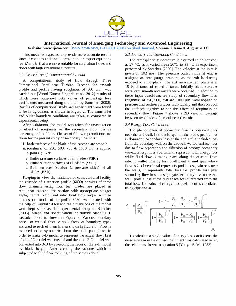
2.4 Energy Loss Calculation
The phenomenon of secondary flow is observed only
near the end wall. In the mid span of the blade, profile loss
is dominant. Secondary loss at the end walls includes loss
from the boundary wall on the endwall wetted surface, loss
due to flow separation and diffusion of passage secondary
vortex. Energy loss coefficients represent total energy loss
while fluid flow is taking place along the cascade from
inlet to outlet. Energy loss coefficient at mid span where
flow is 2- dimensional represents profile loss, whereas near
the walls, it represents total loss i.e. profile loss plus
secondary flow loss. To segregate secondary loss at the end
wall, profile loss at the mid space was subtracted from the
total loss. The value of energy loss coefficient is calculated
using equation-4.
y =
1
01
2
201
0201
1
01
2
1
01
2
201
02011
01
2
111
111
P
P
PP
PP
P
P
P
P
PP
PP
P
P
s
s
s
s
ss
(4)
To calculate a single value of energy loss coefficient, the
mass average value of loss coefficient was calculated using
the relationas shown in equation 5 [Yahya, S. M., 1983].

International Journal of Emerging Technology and Advanced Engineering
Website: www.ijetae.com (ISSN 2250-2459, ISO 9001:2008 Certified Journal, Volume 3, Issue 8, August 2013)
786
=
s
a
s
ay
dyV
dyV
0
0
(5)
Where is the mass average loss coefficient, Va is the
axial velocity, is the density of air, S is the pitch
distance and dy is the elemental length in pitch wise
direction.
III. RESULT AND DISCUSSION
The pressure and velocity vector were analyzed at
appropriate locations in order to understand behavior of the
flow through cascade. Various values of pressure (total as
well as static pressure) at inlet & exit are taken along the
whole blade span. Mass averaged total loss coefficients
were computed along the complete blade span starting from
endwall surface at zero mm to other endwall surface at 95
mm height. In order to visualize the flow near the end wall,
the measurements near the endwalls were taken at small
distances & secondary losses were computed. For first 10
mm height from bottom end wall, measuring points are 2
mm apart from each other. Thereafter, it was computed at
every 5 mm interval till 85 mm blade height. Finally for the
last 10 mm height it was again computed at every 2 mm
interval. Table 1 shows the various intervals at which total
loss coefficients were found.
The total (combined) losses in a blade cascade are
estimated by the energy loss coefficient , which is
essentially the sum of profile loss coefficient & end loss
coefficient as given by Kostyuk and Frolov (1988) in
equation 6.
(total) = (pr) + (sec) (6)
3.1 Effect of Roughness on Total Energy Loss Coefficients:-
First, mass averaged total energy loss coefficients have
been determined using values of total and static pressures at
exit and total pressure at inlet. Mass averaged total loss
coefficients were computed along the complete blade span.
A plot of total energy loss coefficients for cascade PSR
with a roughness of 250μ is shown in Figure 5. End losses
or secondary losses are obtained by subtracting mid span
value of profile loss from individual mass averaged loss
value along the blade height.
It is expected that total energy loss increases till both end
of the blade compared to its value at mid span, but humps
are seen just before both the ends. The presence of humps
at hub and casing occur because of the formation of vortex
cores that leads to increase in local energy loss coefficient.
Comparison of loss coefficient in case of smooth, Both
surfaces Rough (BSR), Pressure Surface Rough (PSR),
Suction Surface Rough (SSR) Cascades for roughness 250
µm has been shown in Figure 6.
It is observed from the Figure 6 that the loss coefficient
is high at hub and casing due to the endwall boundary
layers. The local increase in loss coefficient is observed
due to the secondary flow cores near the hub and casing. It
is also seen that profile loss is lowest for smooth blade and
increases when roughness is applied over pressure, suction
surface separately and together in the same order. The trend
of energy loss coefficient for other roughnesses i.e. 250,
500, 750 and 1000 µm is same. Hence, they are not shown
in graphical form here to avoid repetitiveness but the
results are summarized in table 2. When the roughness of
250𝞵m was applied over pressure and suction surface
separately and together, the profile loss coefficient
increases to 11.71, 15.97 and 17.10% respectively
compared to 10.53% in case of smooth. It can be concluded
that the same roughness is significantly detrimental when
applied over suction surface, whereas it increases
marginally compared to smooth blade value when
roughness is applied over pressure surface. The combine
effect of roughness over pressure and suction surface is
seen when the case of roughness over both the surfaces is
applied together.
3.2 Effect of roughness on Secondary loss :
It is evident from results shown in Figure 6 and Table 2
that difference in percentage values of total energy loss &
Profile loss gives percentage of secondary loss in total
energy. In case of smooth blade secondary loss is 4.94%.
Since the total energy loss is also increased with
application of roughness, in spite of absolute change in
secondary loss, it is not truly reflected in the percentage
change in secondary loss when the absolute change in
secondary loss is non-dimensionalised with total loss with
the same roughness. Therefore, the percentage of secondary
loss in total energy loss is shown in last column of table 2,
has been non-dimensionalised with the total loss in case of
smooth blades.
Presence of roughness over the different part of blade
affects the secondary loss differently. Secondary loss
increases in case of PSR blade cascades compared to
smooth blade.

International Journal of Emerging Technology and Advanced Engineering
Website: www.ijetae.com (ISSN 2250-2459, ISO 9001:2008 Certified Journal, Volume 3, Issue 8, August 2013)
787
The secondary loss further increases slightly if the
roughness over pressure surface is increased from 250 to
500 µm. Roughness on pressure surfaces of PSR cascade
makes boundary layer thicker and thus strengthen the
pressure side vortex and hence passage vortex due to which
the secondary loss is increased. The Pressure side leg of
horse shoe vortex is affected by curvature and pressure
difference between pressure side and suction side of
adjacent blade of the corresponding flow passage thereby
contribute more to the Secondary losses. It can be
concluded that presence of roughness over pressure surface
increases secondary losses. This may be due to favorable
effect of pressure side leg on the passage vortex. This is in
line with the energy loss coefficient where roughness over
pressure surf ace is least detrimental. On the contrary, the
magnitude of secondary loss decreases in case of BSR &
SSR cascades with increase in roughness from 250 to 500
µm. The secondary losses reduces to 2.94, 2.75 and 2.46%
respectively when roughness of 250 µm, 500 µm and 750
µm applied over suction surface. This may be due to
strengthening of suction side counter vortex, which mixes
with the passage vortex and reducing the effect of passage
vortex. Therefore, the secondary losses are lower in this
case. Increase in roughness further enhance counter vortex
and hence secondary losses are further reduced. Profile loss
due to roughness over suction surface also favors these
results. Magnitude of secondary loss at roughness value of
1000 µm was found to be approximately equal to that of
750 µm for all types of cascades i.e. PSR, SSR & BSR.
Table 2 shows that profile loss for BSR cascade is
maximum followed by SSR and PSR. In smooth type of
cascade profile loss is happened to be minimum. It was
observed that the mass averaged secondary loss as
percentage of total loss in smooth blade cascade was
4.94%. When 250 µm roughness was present on both
surfaces together this loss was 4.65%. The secondary loss
further reduces to 4.37% when roughness over both the
surfaces is increased to 500 µm. However, the roughness of
250 µm applied separately over pressure and suction
surfaces results in secondary loss of 5.41% and 2.94%,
respectively. Thus, it is clear that roughness over pressure
surface strengthen the passage vortex, whereas suction side
roughness weakens the passage vortex by stronger suction
side counter vortex. When the roughness over pressure and
suction surface applied together, the effect of counter
vortex is more pronounced, thus causing secondary loss to
decrease in this case.
The effect of different levels of roughnesses (250, 500,
750 &1000 µm) over various surfaces of blades on the
profile and secondary loss are summarized in Table 2.
3.3 Contour plots of total pressure distribution:
Total pressure distribution for BSR cascade over entire
computational domain very close to end wall and at mid
span are shown in Figure 7 and Figure 8. After entering
cascade section total pressure drops due to viscous effect
and other losses over the cascade section. At exit of
cascade wakes are formed where total pressure drops
significantly. However in core flow region, pressure drop is
insignificant. At significant distance from trailing edge
intermixing of core flow and wake takes place. At very
close to end wall region wake bands are much broader &
are much more diffused at very exit from blade trailing
edge because of end wall boundary layer interaction as seen
in Figure 7. Whereas, wakes are very distinct at mid span,
Figure 8.
IV. CONCLUSIONS
The pattern of variation of energy loss coefficient in
spanwise direction (y/S) is same for smooth as well as
rough blades. Moreover the Figure 6 shows that
energy loss coefficient is least for smooth blades and
it reaches the maximum value in case the roughness is
introduced on pressure as well as suction surface
together.
It is observed that applying roughness on blade
surface definitely increases the profile loss as well as
total energy loss coefficient. But the mass averaged
secondary loss is lower than the secondary loss in a
smooth cascade in case of SSR & BSR and higher in
case of PSR compared to smooth blade case.
SSR has least secondary losses may be because of
more flow separation of boundary layer and thus
mixing of passage vortex with suction side counter
vortex takes place resulting into least secondary
losses.
Secondary Loss in BSR is more than SSR because the
roughness over pressure surface promotes passage
vortex, whereas roughness over suction surface
strengthen counter vortex present as suction surface
leg. Therefore, we can say that secondary losses in the
case of pressure surface are more that of suction
surface for the same roughness level.

International Journal of Emerging Technology and Advanced Engineering
Website: www.ijetae.com (ISSN 2250-2459, ISO 9001:2008 Certified Journal, Volume 3, Issue 8, August 2013)
788
Due to the end wall boundary layers the loss
coefficient is high at hub and casing.
Humps are observed near the hub and casing due to
secondary vortex which increases the local energy
loss coefficient.
NOMENCLATURE
Density
ui Velocity vector
Sm Momentum Source Term
P Static Pressure
ig Gravitational Body Force
Fi External Body Force
ij Stress Tensor
Keff Effective Thermal Conductivity
Jj‘ Diffusion Flux
Sh Source term includes heat of chemical reaction
T Temperature
E Energy term
h Enthalpy
P2s Static pressure at outlet
Po1 Total pressure at inlet
Po2 Total pressure at outlet
Ratio of specific heats for air
y Local energy loss coefficient
REFRENCES
[1 ] Brear Michael J., Hodson Howard P., Gonzalez Palom and Harvey
Neil W., 2002, ―Pressure Surface Separations in Low-Pressure Turbines—Part 2: Interactions With the Secondary Flow,‖
Transactions of the ASME, 124, 402-409.
[2 ] Korakianitis T. and Hamakhan I. A., 2010, ―Aerodynamic
Performance Effects of Leading-Edge Geometry in Gas-Turbine
Blades,‖ Applied Energy, 87,1591–1601.
[3 ] Langston L. S., Nice M.L. and Hooper R.M., 1977, ―Three-
Dimensional Flow within a Turbine Cascade Passage, " ASME
Journal of Engineering for Power, 99, 21–28.
[4 ] Lei Qi, ZhengpingZou, Peng Wang, Teng Cao and Huoxing Liu,
2011, ―Control of Secondary Flow Loss in Turbine Cascade by Streamwise Vortex ,‖ Computers & Fluids, 54, 45-55.
[5 ] Mahmood, G.I. and Acharya S., 2007, ―Experimental Investigation
of Secondary Flow Structure in a Blade Passage With and Without Leading Edge Fillets,‖ ASME Journal of Fluids Engineering, 129,
253-262.
[6 ] Marchal P., and Sieverding C.H., 1977, ―Secondary Flows Within
TurbomachineryBladings,‖ Secondary Flows in Turbomachines,‖
AGARD-CP-214, 11, 1–19.
[7 ] Moon, Young J. and Koh Sung-Ryong, 2000, ―Counter-rotating
streamwise vortex formation in turbine cascade with endwall fencing,‖ Computers And Fluids, 30, 473-490.
[8 ] SahaArun K. and AcharyaSumanta, 2008, ―Computations of
Turbulent Flow and Heat Transfer Through a Three-Dimensional Nonaxisymmetric Blade Passage,‖ ASME Journal of
Turbomachinery, 130, 031008-1- 031008-10.
[9 ] Samsher, 2002, ―Effect Of Blade Surface Roughness on Profile Loss
and Exit Angle in A Rectilinear Steam Turbine Cascade,‖ Ph.D.
Thesis, Mech. Engg. Dept. IIT Delhi.
[10 ] Samsher, 2007, ―Effect Of localized roughness over reaction &
impulse Blades on loss coefficient‖ Journal of Power and energy,
part A IMechE, U.K. 221, 21-32
[11 ] Sharma O.P. and Butler T.L, 1987, ―Predictions of Endwall Losses
and Secondary Flows in Axial Flow Turbine Cascades,‖ ASME Journal of Turbo machinery, 109, 229-236.
[12 ] Shih T. I-P. and Lin Y.L, 2003, ―Controlling Secondary-Flow
Structure by Leading-Edge Airfoil Fillet and Inlet Swirl to Reduce Aerodynamic Loss and Surface Heat Transfer,‖ Transactions of the
ASME, 125, 48-56.
[13 ] Sieverding C.H and, Bosch P. Van den, 1983, ―The Use of Coloured
Smoke to Visualise Secondary Flows in a Turbine-Blade Cascade, "
ASME Journal of Fluid Mechanics, 134,85-89.
[14 ] SonodaToyotaka, Hasenjäger Martina, Arima Toshiyuki and
Sendhoff Bernhard, 2009, ―Effect of End Wall Contouring on Performance of Ultra-Low Aspect Ratio Transonic Turbine Inlet
Guide Vanes,‖ ASME Journal of Turbomachinery, 131, 011020-1-
011020-11.
[15 ] Vinod Kumar Singoria, Deepika Sharma, Samsher, 2012 ―Effect of
roughness on secondary flow in a rectilinear turbine‖ proceedings of
conference organized by YMCA University of science & technology, Faridabad, Haryana, India, 132-141.

International Journal of Emerging Technology and Advanced Engineering
Website: www.ijetae.com (ISSN 2250-2459, ISO 9001:2008 Certified Journal, Volume 3, Issue 8, August 2013)
789
[16 ] Wang H.P., Olson S.J., Goldstein R.J., Eckert E.R.G., 1997, ―Flow
visualization in a linear turbine cascade of high performance turbine blades,‖ ASME Journal of Turbomachinery, 119, 1-8.
[17 ] Yahya, S. M., 1983, Turbines, compressors and fans, Tata McGraw-
Hill, New- Delhi.
[18 ] Vinod Kumar Singoria, Samsher, 2013, ―Mechanism,
Characterization, Pattern and Effect of Roughness over Turbine Blade: A Review‖ International Journal of Engineering and
Innovative Technology (IJEIT), 2, 191-200.
Figures and graphs

International Journal of Emerging Technology and Advanced Engineering
Website: www.ijetae.com (ISSN 2250-2459, ISO 9001:2008 Certified Journal, Volume 3, Issue 8, August 2013)
790

International Journal of Emerging Technology and Advanced Engineering
Website: www.ijetae.com (ISSN 2250-2459, ISO 9001:2008 Certified Journal, Volume 3, Issue 8, August 2013)
791
Figure 3: schematic diagram and specifications of turbine blade 6030 cascade

International Journal of Emerging Technology and Advanced Engineering
Website: www.ijetae.com (ISSN 2250-2459, ISO 9001:2008 Certified Journal, Volume 3, Issue 8, August 2013)
792
Figure 4: Measurement plane at 15% of the chord

International Journal of Emerging Technology and Advanced Engineering
Website: www.ijetae.com (ISSN 2250-2459, ISO 9001:2008 Certified Journal, Volume 3, Issue 8, August 2013)
793

International Journal of Emerging Technology and Advanced Engineering
Website: www.ijetae.com (ISSN 2250-2459, ISO 9001:2008 Certified Journal, Volume 3, Issue 8, August 2013)
794

International Journal of Emerging Technology and Advanced Engineering
Website: www.ijetae.com (ISSN 2250-2459, ISO 9001:2008 Certified Journal, Volume 3, Issue 8, August 2013)
795
Figure 7: Total pressure distributions in wake region very close to end wall of BSR cascade having Roughness of 500 𝞵m.
Figure 8: Total pressure distributions in wake region at mid span of BSR cascade having Roughness of 500 𝞵m.

International Journal of Emerging Technology and Advanced Engineering
Website: www.ijetae.com (ISSN 2250-2459, ISO 9001:2008 Certified Journal, Volume 3, Issue 8, August 2013)
796
Table 1
Non dimensional distance on blade span
S.N Distance from
bottom wall mm)
Non Dimensional
Distance
S.N. Distance from
bottom wall
(mm)
Non Dimensional
Distance
1 0 0 14 50 0.53
2 2 0.02 15 55 0.58
3 4 0.04 16 60 0.63
4 6 0.06 17 65 0.68
5 8 0.08 18 70 0.74
6 10 0.11 19 75 0.79
7 15 0.16 20 80 0.84
8 20 0.21 21 90 0.95
9 25 0.26 22 87 0.92
10 30 0.32 23 89 0.94
11 35 0.37 24 91 0.96
12 40 0.42 25 93 0.98
13 45 0.47 26 95 1

International Journal of Emerging Technology and Advanced Engineering
Website: www.ijetae.com (ISSN 2250-2459, ISO 9001:2008 Certified Journal, Volume 3, Issue 8, August 2013)
797
Table 2
Summary of Total Energy Loss, Profile Loss and Secondary Loss for smooth, SSR, PSR & BSR cascades for different levels of roughness
Location of
roughness
Roughness
levels
(𝞵m)
Percentage of
Total energy loss
in total energy of
the air (A)
Percentage of
Profile loss in total
energy of the air (B)
(mid span value)
Contribution of
secondary loss (C=A-B)
percentage of Secondary
loss relative to total loss
in smooth blades
(D=100*C/A)
Smooth 10.53 10.01 0.52 4.94
PSR 250 11.71 11.14 0.57 5.41
500 12.24 11.61 0.63 5.98
750 12.33 11.73 0.61 5.79
1000 12.33 11.73 0.61 5.79
SSR 250 15.97 15.66 0.31 2.94
500 17.78 17.49 0.29 2.75
750 17.96 17.7 0.26 2.47
1000 17.96 17.7 0.26 2.47
BSR 250 17.10 16.61 0.49 4.65
500 19.42 18.95 0.46 4.37
750 19.72 19.25 0.46 4.37
1000 19.72 19.25 0.46 4.37


![INTRODUCTION & RECTILINEAR KINEMATICS: CONTINUOUS …students.eng.fiu.edu/leonel/EGM3503/Chapter 12... · RECTILINEAR KINEMATICS: CONTINIOUS MOTION [Section 12.2] A particle travels](https://static.fdocuments.in/doc/165x107/5ebaba577e6ff33c54352bed/introduction-rectilinear-kinematics-continuous-12-rectilinear-kinematics.jpg)
