The Study of Concrete Durability in the Case of Jinan...
66
The Study of Concrete Durability in the Case of Jinan Yellow River Highway Bridge Master of Science Thesis in the Master’s Programme of Infrastructure and Environmental Engineering HUINING WANG Department of Civil and Environmental Engineering Division of Building Technology CHALMERS UNIVERSITY OF TECHNOLOGY Gothenburg, Sweden 2014 Master’s Thesis 2014:32
Transcript of The Study of Concrete Durability in the Case of Jinan...

The Study of Concrete Durability in the Case of Jinan Yellow River Highway Bridge Master of Science Thesis in the Master’s Programme of
Infrastructure and Environmental Engineering
HUINING WANG Department of Civil and Environmental Engineering Division of Building Technology CHALMERS UNIVERSITY OF TECHNOLOGY Gothenburg, Sweden 2014 Master’s Thesis 2014:32


MASTER’S THESIS 2014:32
The Study of Concrete Durability in the Case of Jinan
Yellow River Highway Bridge
Master of Science Thesis in the Master’s Programme
HUINING WANG
Department of Civil and Environmental Engineering
Division of Building Technology
CHALMERS UNIVERSITY OF TECHNOLOGY
Gothenburg, Sweden 2014

The Study of Concrete Durability in the Case of Jinan Yellow River Highway Bridge
Master of Science Thesis in the Master’s Programme
HUINING WANG
© HUINING WANG, 2014
Examensarbete / Institutionen för bygg- och miljöteknik,
Chalmers tekniska högskola 2014:32
Department of Civil and Environmental Engineering
Division of Building Technology
Chalmers University of Technology
SE-412 96 Gothenburg
Sweden
Telephone: + 46 (0)31-772 1000
Cover picture: The picture shows the Jinan Yellow River Highway Bridge, which is a
double tower and double cable planes suspension cable-stayed bridge (Broadcaster,
2012).
Department of Civil and Environmental Engineering Gothenburg, Sweden 2014

I
The Study of Concrete Durability in the Case of Jinan Yellow River Highway Bridge
Master of Science Thesis in the Master’s Programme
HUINING WANG Department of Civil and Environmental Engineering
Division of Building Technology
Chalmers University of Technology
Abstract Reinforced concrete has been commonly used in China as the most popular structural
material in many infrastructures. However, since these structures have served for
several decades, problems of concrete durability gradually arise due to severe service
environment or air pollution of increasing CO2 concentration. The durability of the
reinforced concrete structures principally depends on the optimization of five factors.
They are structure design, construction operation, management and maintenance,
material properties and the external environmental conditions. These five factors are
closely correlated with each other so that the durability will be markedly reduced if
one of them is poor. Without adequate durability, the reinforced concrete structure
may deteriorate either due to concrete damages or due to reinforcement corrosion. The
main reasons behind are concrete carbonation, chloride ion ingress, alkali-aggregate
reactions and freeze-thaw cycles. In this study the influences of five factors on the
concrete durability were analysed. Further investigation was made regarding the
deterioration of reinforced concrete.
As a case study Jinan Yellow River Highway Bridge was inspected in the aspect of
concrete durability. The result shows that most of the chambers inspected in Jinan
Yellow River Highway Bridge are in a good condition. Concrete suffers slightly from
carbonation but the thickness of carbonation depth is far less than the concrete cover.
The reinforcement is not likely to be corroded. However, in some testing chambers
there are problems with inadequate thickness of concrete cover and cracks. These
problems can be treated by pasting cement mortar, which is for safety consideration.
Key words: concrete durability, reinforced concrete deterioration, concrete damage,
reinforcement corrosion

CHALMERS, Civil and Environmental Engineering, Master’s Thesis 2014:32 II

CHALMERS Civil and Environmental Engineering, Master’s Thesis 2014:32 III
Contents
ABSTRACT I
CONTENTS III
PREFACE V
NOTATIONS VI
1 INTRODUCTION 1
1.1 Aim and objectives 1
1.2 Methodology 2
2 FACTORS INFLUENCING CONCRETE DURABILITY 3
2.1 Structure design 4
2.2 Construction operation 5
2.3 Management and maintenance 7
2.4 Material properties 7
2.5 External environmental condition 9
3 REINFORCED CONCRETE DETERIORATION 13
3.1 Carbonation 13
3.1.1 Carbonation mechanism 13
3.1.2 Environment factors influencing carbonation 14
3.1.3 Material properties influencing carbonation 15
3.2 Chloride ion penetration 16
3.2.1 Chloride ion penetration mechanism 16
3.2.2 Chloride ion and diffusion influencing chloride ingress 18
3.2.3 Concrete properties influencing chloride ingress 19
3.2.4 Reinforcement corrosion due to chloride ingress 20
3.3 Concrete alkali-aggregate reactions 20
3.3.1 Types of reactions 20
3.3.2 Conditions that cause alkali-aggregate reaction 21
3.3.3 Concrete damage due to alkali-aggregate reaction 22
3.4 Freeze-thaw cycles 22
3.4.1 Mechanism of freeze-thaw cycles 22
3.4.2 Factors influencing freeze-thaw cycles 23
4 BACKGROUND DESCRIPTION 25
4.1 Description of Jinan Yellow River Highway Bridge 25
4.2 Previous inspection and maintenance 27

CHALMERS, Civil and Environmental Engineering, Master’s Thesis 2014:32 IV
4.3 Geographical environment 28
4.4 Hydrogeological description 29
4.5 Meteorological characteristics 30
4.6 Environmental classification based on concrete durability 30
5 METHOD AND MEASUREMENT 32
5.1 Visual inspection 33
5.2 Non-destructive test 34
6 RESULT 38
6.1 Concrete damage by visual inspection 38
6.2 Concrete strength and carbonation depth 42
6.3 Reinforcement position and concrete cover 44
6.4 Reinforcement corrosion 45
6.5 Concrete resistivity 46
6.6 Chloride concentration in concrete 48
6.7 Summary 48
7 DISCUSSION AND SUGGESTIONS 50
8 CONCLUSIONS 52
9 REFERENCES 53
10 APPENDIX 55

CHALMERS Civil and Environmental Engineering, Master’s Thesis 2014:32 V
Preface This master thesis has been carried out from January 2014 to June 2014, at the
Division of Building Technology in the Department of Civil and Environmental
Engineering, Chalmers University of Technology, Sweden. The project has been
performed at Shandong Highway Engineering Consulting Company, Jinan, Shandong
province, China.
I would like to thank Luping Tang, my supervisor at Chalmers for your positive
attitude and for supporting me throughout my master thesis work.
Special thank also goes to my supervisor Aimin Sha in Chang’an University, China,
who will be my future Doctoral supervisor in Chang’an University, for your guidance
and for sharing your knowledge with me.
For patiently answering my questions, I thank Xiaohui Song and Feiping Xu at the
Jinan Yellow River Highway Bridge Administration as well as to Renshan Chen for
inspiring discussions and ideas.
I would also like to express my gratitude to Xibin Zhang for giving me the
opportunity to do my thesis within your company and for all of the advice and data
that I used during this thesis.
Finally I would like to thank everyone at the Shandong Highway Engineering
Consulting Company for the experience that we had together.
Gothenburg, June 11, 2014
Huining Wang

CHALMERS, Civil and Environmental Engineering, Master’s Thesis 2014:32 VI
Notations
Concrete carbonation
X - Depth of carbonation (m)
t - Time of exposure (s)
C - Carbonation coefficient. -
Chloride ion ingress
CCl - Concentration of chloride ion (%)
x - Location (cm)
DCl - Diffusion coefficient -
Concrete strength test
Rm - Estimation value of average concrete strength (MPa)
Rmα - Average concrete strength in non-horizontal direction (MPa)
Raα - Corrected concrete strength measured in angle α (MPa)
Kbt - Estimation value of strength uniformity coefficient -
Kbm - Average strength uniformity coefficient -
dm – Carbonation depth (mm)
Rit - Estimation value of average concrete strength (MPa)
Rim - Conversion value of average concrete strength (MPa)
R - Design value of concrete strength (MPa)
Concrete cover thickness test
- Average thickness of concrete cover for n points (mm)
Dne - Characteristic value of concrete cover thickness (mm)
Dnd – Designed values of concrete cover thickness (mm)
- Average thickness of concrete cover (mm)
K - Qualified determination coefficient -

CHALMERS, Civil and Environmental Engineering, Master’s Thesis 2014:32 1
1 INTRODUCTION
With the rapid development of road construction in China, reinforced concrete has
been commonly used as the main structural material in many infrastructures.
Generally, it is not easy for the reinforcement to be corroded since it is under the
protection of concrete (Neville, 1995). However after these structures have already
served for several decades, aging problems gradually arise with reinforced concrete
structures due to long period of time and increase of traffic loads. Severe service
environment such as marine and industrial environment or polluted air with high CO2
concentration can also degrade the performance of reinforced concrete structures.
Durability of concrete, which is a well-known term, has drawn great attention in the
field of building technology. Durability expresses the ability of the material to keep its
original properties unchanged over time (Wang, 2006). Usually structure with
inadequate durability fails to reach its expected service life, thus generating a huge
amount of maintenance cost every year. Furthermore, it also causes reduction in
strength and may threaten the safety of the structure.
Shandong province, which locates in the east part of China, has a large number of
highways and bridges. Jinan Yellow River Highway Bridge located in Jinan (the
capital city of Shandong) was built in 1978 and it has been serving for more than 30
years. It is one of the first long-span cable-stayed highway bridges in China. Due to
the growing traffic loads, unfavourable environmental conditions, and material
degradation, the bridge has been previously overhauled in 1995, 2003 and 2008 (Song
et al., 2009). It would be interesting to check nowadays condition of the bridge and to
evaluate the durability of reinforced concrete structures.
1.1 Aim and objectives
The aim of this study is to analyse the factors that influence the durability of
reinforced concrete structures in China through both literature and case studies. The
objectives of the work include the following points.
Study the reasons and mechanisms of reinforced concrete deterioration,
Evaluate the current condition of the reinforced concrete structures in Jinan Yellow
River Highway Bridge,
Investigate which kind of damages in the aspect of concrete durability, and
Propose possible countermeasures that can improve the durability of concrete.

CHALMERS, Civil and Environmental Engineering, Master’s Thesis 2014:32 2
1.2 Methodology
A literature study on concrete durability and relevant damage in reinforced concrete
structures in China will be carried out. Jinan Yellow River Highway Bridge in China
will be taken as an example of case study by means of visual inspections and non-
destructive testing on the selected chambers of the bridge in the aspect of durability
of concrete structure, see Figure 1.
Figure 1 An overview of the work progress used in order to achieve the aim of the
project.

CHALMERS, Civil and Environmental Engineering, Master’s Thesis 2014:32 3
2 FACTORS INFLUENCING CONCRETE
DURABILITY
The durability of a structure is its ability to serve its anticipated purposes for a long
period of time, or at least during its expected service life. In reality, durability of a
structure is the ability to maintain the performance of its own functionality under
natural environment, serving environment and the physical and chemical actions of
internal materials (Li, 2012). However, although a durable structure is expected to
serve without deterioration rehabilitation is needed before running out of its designed
life; a good concrete durability is not a substitution for a good maintenance. Even
though the structure has been designed for a higher durability standard, routine
inspections and regular monitoring are required. Otherwise, reduced performance of
the concrete structures caused by lack of durability may occur. And this can lead to
the discount of bearing capacity concrete structures and in ultimate affect the safety of
the whole structure (Li, 2012).
Nowadays, it is commonly recognized that the durability of the reinforced concrete
structures principally depends on the optimization of five major factors. They are
structure design, construction operation, management and maintenance, material
properties and the external environmental conditions. As it is illustrated in Figure 2,
these factors cover every step in the design, construction, use, management and
maintenance of the concrete structure. They are closely correlated with each other so
that the durability of reinforced concrete structures will be strongly reduced if one of
them is poor.

CHALMERS, Civil and Environmental Engineering, Master’s Thesis 2014:32 4
Figure 2 How the different factors influence the durability and the performance of reinforced concrete structures
2.1 Structure design
Correct design is the first requirement for a durable structure (Li, 2012). However,
due to inadequate standards and technical specifications, underestimation of service
loads and poor information about environmental conditions, the serviceability of the
structures will be greatly shortened.
In China, structural design specifications and technical standards mainly consider the
structural safety under loading, while durability design under environmental effects is
regarded in a secondary position. With the change of construction condition and
environmental conditions, standards in terms of structure durability cannot keep pace
with the times. Regarding the specific detailed design, there are some loopholes such
as the thickness of the concrete cover, bridge drainage facilities and working
environment (Li, 2012). For example, the lack of concrete cover for reinforcement has
been identified as a major problem associated with “failures” in reinforced concrete
bridges. Those could lead to insufficient durability of the bridge structure.
Deterioration of many reinforced concrete structures will occur in hostile environment.
The lack of relevant data or incorrect prediction of high traffic loads can lead to
inaccurate estimation of service loads. Examples of structure damage due to
CHALMERS, Civil and Environmental Engineering, Master’s Thesis 2014:32 5
underestimated loads are recorded worldwide, but they cannot equally be considered
or treated. On the contrary, damage to failure of concrete structures related with loads
other than those expected in the design period is more frequent.
With the rapid development of road construction in China, it was recorded that in the
end of year 1998, there were 210,000 Highway bridges in China under service (Tan,
2005). After they have already served for several decades, some aging problems with
reinforced concrete structures appear. However, most of the bridges are lack of
routine maintenance. Furthermore, along with the increasing volume of traffic, the
previous highways and bridges designed for lower vehicle load standards are still in
operation. It demands the highways and bridges much to satisfy the requirements of
the current vehicle load standards. Since bridges have been under overload conditions
for a long time, the durability of reinforced concrete structures will be rapidly
declined.
Structures damaged due to a wrong appraisal of the environmental aggressiveness happen
frequently all over the places. The inferior durability characteristics of concrete may
be caused by the severe environment conditions that the concrete is subjected to. It is
generally recognized that the concrete durability can be influenced by the following
environmental factors (Li, 2012):
- Temperature
- Moisture
- Physical factors
- Chemical factors
- Biological factors
These factors can be attributed to weathering conditions such as dramatic change in
temperature or moisture, or to abrasion such as explosion to harmful liquids and gases
both naturally and industrially, or explosion to biological agents.
2.2 Construction operation
In China, many bridges generate damages and deterioration problems though they
have not yet reached the expected service life. Even some bridges have serious
durability issues soon after they are put into operation. In most cases, the reason
behind is that the construction quality of most bridges fails to meet the design
requirements and technical specifications (Li, 2012). If that is the case, potential
construction problems could be the bad practice in construction process.
In pursuit of the economic benefits, some construction companies in China have to
adopt low-quality construction technology and methods in construction process.
Examples could be the use of substandard materials, insufficient thickness of concrete
cover, lack of grouting or the use of steel that has already been corroded in
construction work. This does not meet the requirements of construction quality and

CHALMERS, Civil and Environmental Engineering, Master’s Thesis 2014:32 6
design specifications, thus inevitably leading to deterioration in durability and posing
serious threat to bridge structures.
The costs of a construction project include time, personnel and equipment. Any cost
saving effort is therefore justified, but any possible solution should not decrease the
durability and the service life of the concrete structure. In China, because of the rising
costs of labour, advanced demolding and shortening construction period become the
major solution to the project costs. Traditional cement products with long developing
period of early strength are replaced by rapid Portland cement with fast developing of
early strength and admixture products (Li, 2012). This is because the rapid Portland
cement is able to meet the strength requirements within 24-72 hours. However, it
brings the shortcomings that the late strength of concrete is no longer growing. And
this affects the durability of reinforced concrete structures since the performance of
reinforced concrete structures exposed to severe environments depends on the
maximum strength that can be achieved rather than the 28-day strength (Liu, 2013).
The strength of traditional concrete can grow gradually at a later stage, instead
nowadays the strength of the concrete in some cases is only increased by 5%, and
sometimes the strength of the concrete has even reduced (Liu, 2013).
When it comes to the raw materials in concrete production, in some developing areas
in China, aggregate processing equipment is far from advanced, and thus poor quality
of aggregates is obtained. Poor aggregates may have the problems such as bad grain
shape, excess flakiness particles, large porosity, poor grading, etc. Therefore, when
the concrete is formulated for the same strength class and workability, cement content
are significantly higher than the level established by the standards of good practice in
advanced areas. In order to improve the workability of the mixes, the unit volume of
water should be therefore higher. Thus the water to cement (W/C) ratio is increased.
The limitation of W/C ratio is perhaps the most essential specification that affects the
strength and durability of reinforced concrete (Lin, 2013). Higher W/C ratio can lead
to a lower strength, larger permeability and lower durability of reinforced concrete
structures (Lin, 2013). The stability of volume in hardened concrete also decreases.
This will make the concrete easy to generate cracks.
Curing aims to provide the concrete the best final performance. Correct curing
involves preserving the suitable moisture content in concrete until the hydration of
concrete has completely finished (Liu, 2005). Appropriate temperature is another
important factor in curing stage. Due to the improvement of current grade of concrete,
the use of cement grade also increases with accelerated hydration rate (Liu, 2005).
With a small W/C ratio, bleeding is significantly reduced. Though this helps to
enhance the strength of aggregate and the strength at cement interface, it can easily
lead to plastic shrinkage cracks due to insufficient supplement of surface water
evaporation. This will not only affect the development of concrete strength, the
durability of reinforced concrete structures will be significantly weakened as well.

CHALMERS, Civil and Environmental Engineering, Master’s Thesis 2014:32 7
2.3 Management and maintenance
In China, general contractors are used to undertake most of the concrete work and
subcontract part of its work to other small companies. Then subcontractors separate
the project work to each process. This behaviour can break the continuity of concrete
construction and the quality of the reinforced concrete structures cannot be guaranteed.
In order to shorten the construction period and keep the costs down, some
construction companies in China rush contract progress and drive time limit. As a
consequent, the quality of the construction usually cannot be guaranteed. This will
bring danger to the safety and durability of the structure sooner or later.
Even some construction engineers fail to understand correctly the drawings and
blindly guide the construction work. Some supervisors cannot strictly fulfil their
responsibilities of controlling the construction quality in every step. This will result in
defects in construction quality.
The durability of the reinforced concrete structure is closely related to the reasonable
usage and proper maintenance. Maintenance includes normal inspection, continuous
monitoring of the structure, as well as repair and rehabilitation. They are necessary to
ensure normal bridge operations. Inspection is meant to detect any sign of
deterioration before the deteriorating process becomes too advanced. Durability issues
will occur if the personnel fail to discover the durability problems during the bridge
inspection or have already discovered without attention. Even little damage is not
properly maintained in time; the damages can be cumulative over time and cause
danger to the reinforced concrete structures.
2.4 Material properties
In reinforced concrete, the most critical property of concrete is permeability and
diffusion. Gases, liquids and ions in the concrete can move through concrete when
there is a difference in the pressure of air or water, or in the concentration of ions
(Zhang et al., 2007). Pressure caused by the difference in humidity or temperature
also makes gases or water enter the concrete. Under the influence of chemical
potential or electric field, transport of fluids or ions through the concrete can also
occur.
Gases, liquids and ions can travel through concrete in three different ways:
permeation, diffusion, and sorption (Zhang et al., 2007). Permeation means they can
flow under a pressure gradient. Diffusion occurs under a concentration gradient. And
flow under capillary suction is referred to sorption. The main reason why the concrete
material has a certain degree of transport properties is that there exist a large number
of pores and cracks in concrete. The pore structure of the concrete includes pores in
cement slurry, pores in the aggregates, pores at the interface between aggregates and
paste (Zhang et al., 2007). Adverse construction can also result in some honeycomb

CHALMERS, Civil and Environmental Engineering, Master’s Thesis 2014:32 8
structures. The porosity in general aggregates is normally not more than 5%, and the
porosity in the concrete is about 15% (Liu, 2013).
As previously described, all processes causing deterioration of the concrete or
corrosion of the reinforcement bars involve transport phenomena through the pores
and cracks of the concrete. When the harmful substances penetrate into the concrete,
chemical reactions occur between the substances and the component of the concrete.
It damages the structure of concrete, resulting in durability problems in concrete
structures. There are three fluids/gases principally relevant to the durability of the
concrete: they are pure water, water with aggressive ions (Cl-), and harmful gases
such as carbon dioxide, oxygen and sulphur dioxide (Vagelis et al., 1991). The fluids
may move in the concrete in different manners, the mobility depends on the
permeability of the concrete.
The deterioration process of concrete is revealed in Figure 3. Firstly, the
environmental erosion factors destroy the surface concrete, leading to reinforcement
corrosion and alkali-aggregate reaction in concrete. Most of these changes are
accompanied by the volume expansion. Stresses derived from concrete expansion
generate more cracks in concrete (Li, 2012). Therefore, the permeability of concrete is
further increased, making the invasion of substances more rapidly. This will cause a
wide range of cycle of damages to concrete structures.
Figure 3 The deterioration process of reinforced concrete due to material properties
and external environmental factors

CHALMERS, Civil and Environmental Engineering, Master’s Thesis 2014:32 9
Freeze-thaw resistance is one important indicator closely related to the durability of
concrete. Dry concrete will not suffer from frost damage. When the moisture content
in concrete exceeds a critical value and the surrounding temperature decreases, water
in some of the pores becomes freezing with volume expansion (Lulu et al., 2001).
This forces the water in unfrozen pores migrating outward through the frozen zone.
Hydrostatic pressure is generated as a result. When the hydrostatic pressure exceeds
the meso strength of concrete, the concrete pore wall structures get destroyed. Internal
crack in concrete gradually extends outward (Lulu et al., 2001). With the cyclical
changes of surrounding temperature, water inside the concrete becomes ice and then
ice melts into water. After a few cycles, damages in the internal structure of concrete
continue to accumulate, eventually leading to the destruction of the concrete. And
these are all closely related to the permeability of concrete.
Figure 4 shows the relationship
between water absorption and
concrete resistance to freeze-thaw
cycles. The logarithmic of water
absorption capacity of the concrete
is inversely proportional to the
logarithmic of freeze-thaw cycling
resistance of the concrete. It can be
seen that the lower the water
absorption capacity of concrete,
the better the freeze-thaw cycling
resistance.
2.5 External environmental condition
Concrete structures are normally located in the aggressive environment that can
generate various kinds of external attacks. Usually, the external environment provides
agent that can cause corrosion in reinforcement. It mainly includes water, oxygen,
carbon dioxide and aggressive ions. There are also external actions that can cause
uneven stress distribution in concrete such as freeze-thaw action, wetting and drying
conditions, heating and cooling effects, loading and unloading on the structure, and
etc. Acid attack, sulphate attack, microbiological attack and other kinds of physical
and chemical attack could also damage the concrete exposed to the surrounding
environment (Vagelis et al., 1991). Marine structures and structures close to coastal
waters are particularly in danger of the reinforcement corrosion due to the ingress of
chloride ions from sea water splash and coastal air.
Gas types, concentration and surrounding moisture content determine the extent of
concrete eroded by gases. As it is shown in Table 1, with increasing moisture content
in external environment, concrete become much eroded. Compared to the plain
Figure 4 The relationship between water
absorption ability of concrete and the resistance
to freeze-thaw cycles (freeze-thaw cycles when
concrete is damaged) (Liu, 2013).

CHALMERS, Civil and Environmental Engineering, Master’s Thesis 2014:32 10
concrete, reinforced concrete turns more easily eroded since the reinforced bars are
more vulnerable to the aggressive environment than the concrete.
Table 1 The influence of aggressive gases or aggressive ions to plain or reinforced
concrete under different moisture content and different concentration of gases (Zhang,
2012)
Moisture content (%)
≥75 60-75 ≤60
Agents Conc. (mg/m3)
Plain concrete
Rein- forced concrete
Plain concrete
Rein- forced concrete
Plain concrete
Rein- forced concrete
Cl2 1-5 0.1-1
Slight No effect
Serious Medium
Slight No effect
Medium Slight
No effect No effect
Slight No effect
HCl 1-15 0.05-1
Medium Slight
Serious Medium
Slight No effect
Serious Medium
No effect No effect
Medium Slight
NO2 5-25 1-10
Medium Slight
Serious Medium
Slight No effect
Medium Slight
No effect No effect
Slight No effect
H2S 10-100001-10
Slight Slight
Medium Medium
Slight No effect
Medium Slight
No effect No effect
Slight No effect
HF 10-50 No effect Slight No effect Slight No effect No effect
SO2 10-200 1-10
Slight Slight
Serious Medium
Slight No effect
Medium Slight
No effect No effect
Slight No effect
H2SO4 Much Less or no
Medium Slight
Serious Medium
No effect No effect
Slight Slight
No effect No effect
Slight Slight
CH3COOH
Much Less or no
Medium Slight
Serious Medium
No effect No effect
Slight Slight
No effect No effect
Slight Slight
CO2 NH3 Alkali steam
>2000 >20 Much
No effect No effect Medium
Slight Slight Medium
No effect No effect No effect
Slight Slight Slight
No effect No effect No effect
No effect No effect No effect
When it comes to liquid ingress, groundwater is an important carrier of many
corrosive ions. The chemical composition of groundwater is closely related to the rock
composition, characteristics of soil, the ingredients of supplied water, the distance
from rivers and other surface water and local climatic conditions (Zhang, 2012).
Microorganisms also have an impact on the chemical composition of groundwater. In
mineralized groundwater, the concentration of SO42-
possibly is very high as well as a
large amount of cations combined with SO42-
such as Ca2+
, Mg2+
, Na+ and K
+. In deep
groundwater, there also contains a lot of CO2 (Zhang, 2012). The influence of
aggressive ions in liquids to the concrete structure is shown in Table 2, and there is no
difference in the corrosion of reinforced concrete and plain concrete.
CHALMERS, Civil and Environmental Engineering, Master’s Thesis 2014:32 11
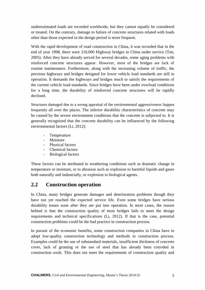
Table 2 The influence of aggressive ions in liquids to plain or reinforced concrete
under different ion concentration (Zhang, 2012)
Agents Concentration Plain concrete
Reinforced concrete
H+ (pH)
1-3 3-4.5 4.5-6
Serious Medium Slight
Serious Medium Slight
CO2 (mg/L)
>40 Slight Slight
SO42- in sulfate
(mg/L)
>4000 1000-4000 250-1000
Serious Medium Slight
Serious Medium Slight
Cl- in chlorine salt (mg/L)
>5000 500-5000 <500
Medium Slight No effect
Medium Slight No effect
Mg2+ in magnesium salt (mg/L)
>4000 3000-4000 1500-3000
Serious Medium Slight
Serious Medium Slight
NH4+ in ammonium salt
(mg/L)
>1000 800-1000 500-800
Serious Medium Slight
Serious Medium Slight
Na+/K+ in caustic alkali (mg/L)
50000-100000 <50000
Slight No effect
Slight No effect
Possible solid agents in contact with the concrete structure that can cause erosion are:
dry soil with salt compounds, fertilizers, pigments, pesticides, herbicides and other
unconsolidated chemical products. The humidity of the suspended powder substance
determines to what extent the concrete structure is eroded. Because erosion happens
only when solid agents are in the liquid phase. Otherwise when the solid agents
absorb water from atmosphere, groundwater and surface water, it produces solution in
concrete and erosion occurs. Category of solids agents is shown in detail in Table 3.
Table 3 The influence of aggressive solids to plain or reinforced concrete under different
solubility and moisture content (Zhang, 2012)
Solubility in water
Agents Moisture content (%)
Plain concrete
Reinforced concrete
Hard Silicate,CaPO3,CaCO3,BaCO3
PbCO3,CaSO3,BaSO4,PbSO4,
MgO,Fe2O3,CrO,Al2O3,SiO2,
and Hydroxide
≥75 60-75 <60
No effect No effect No effect
Slight No effect No effect

CHALMERS, Civil and Environmental Engineering, Master’s Thesis 2014:32 12
Solubility in water
Agents Moisture content (%)
Plain concrete
Reinforced concrete
Easy NaCl, KCl, LiCl
≥75 60-75 <60
No effect No effect No effect
Serious Medium
Slight
Na2SO4,K2SO4,Li2SO4 (NH4)2SO4, NH4Cl
≥75 60-75 <60
Slight No effect No effect
Slight Medium
Slight
KNO3, NaNO3, NH4NO3, LiNO3
≥75 60-75 <60
Serious Medium
Slight
Medium Slight Slight
Na2CO3, K2CO3, (NH4)2CO3
NaHCO3, KHCO3, NH4CO3
≥75 60-75 <60
Slight Slight
No effect
Slight Slight
No effect
MgCl2, CaCl2, AlCl3, ZnCl2
FeCl2, FeCl2, CuCl2 ≥75
60-75 <60
Medium Medium
Slight
Slight Medium Medium
CdSO4, MgSO4, NiSO4, MnSO4,ZnSO4,FeSO4,
Fe2(SO4)3, CuSO4
≥75 60-75 <60
Serious Medium
Slight
Slight Medium
Slight
NaNO3, Zn(NO3)2, NH4NO3, NaNO2,
Zn(NO2)2 NH4NO2, CO(NH2)2
≥75 60-75 <60
Slight Slight
No effect
Slight Slight
No effect
NaOH, KOH
≥75 60-75 <60
Medium Slight Slight
Medium Slight Slight

CHALMERS, Civil and Environmental Engineering, Master’s Thesis 2014:32 13
3 REINFORCED CONCRETE
DETERIORATION
A reinforced concrete structure may deteriorate either due to deterioration of the
concrete itself or due to the corrosion of reinforced bars inside the concrete. There are
different causes of concrete deterioration such as alkali-aggregate reactions, chemical
attack by acids, sulphates, and alkalis, freeze-thaw cycles, fire and abrasion (Li, 2012).
In reinforced concrete, the most serious deterioration mechanisms are those leading to
the corrosion of the reinforcement, resulting in a reduction in effective cross-section
area of reinforcement bars. This will ultimately disrupt the concrete caused by the
cracking of the concrete covers.
However, there is always misunderstanding that the carbonation and penetration of
chloride ions would be the reason of concrete deterioration. As it happens,
reinforcement corrosion occurs only after de-passivation of steels in concrete due to
carbonation of the surrounding concrete, chloride ingress or a combination of both.
Carbonation and chloride ingress would not cause any harm to the concrete itself.
Deterioration of concrete is not the common problem. Generally, if there is any
problem related to the durability of the concrete structure, it is mostly the corrosion of
the reinforcement bars that are more likely to be the main reason.
3.1 Carbonation
Early concrete is generally alkaline and the pH value is as high as 13, which generates
a layer of dense oxide (always called passivation layer) on the surface of reinforced
concrete (Wang, 2006). It plays an important role of protecting the steels in concrete
from rusting. When acidic substances from air, soil or groundwater go through the
concrete surface, they can react with the alkalis in concrete and neutralization occurs.
Since the carbon dioxide in the air is the most common agent that has an effect on
concrete, the process of neutralization is called carbonation.
Carbonation does not cause deterioration of concrete itself but it has an important
effect on the durability of reinforced concrete structures. Nowadays, with the
increasing development of urbanization, the level of atmospheric CO2 comes to rise
for a long time. In addition, a large amount of excreted waste from factories gradually
raises the concentration of CO2 in rivers and groundwater. Carbonation of concrete
becomes the most common problem of many reinforced structures in China.
3.1.1 Carbonation mechanism
The process of concrete carbonation can be expressed by the Equations (1), (2) and
(3). When carbon dioxide diffuses into the concrete, if water is available, it reacts with

CHALMERS, Civil and Environmental Engineering, Master’s Thesis 2014:32 14
calcium hydroxide to form calcium carbonate (Wang, 2006). In concrete if there is
sufficient calcium hydroxide in concrete and the reaction of Equation (3) is
insignificant in the most cases. Thus no significant damage of concrete occurs due to
carbonation.
(1)
(2)
(3)
Calcium carbonate produced from carbonation of concrete may exist in crystalline
forms. Carbonation takes place even at very small CO2 content. For example, it can
happen at the CO2 content of 0.03%, which is a common value in rural areas (Kwan &
Wong, 2005). In an unventilated room, the concentration of CO2 may rise to about 0.1%
typically. In large cities, CO2 content can be at present of 0.3% on average and
exceptionally up to 1% (Kwan & Wong, 2005). It may be slightly higher in industrial
areas. The highest concentration of CO2 is most likely to be observed in vehicle
tunnels since the exhaust emission from motor vehicles contribute to a large part of
CO2.
The mechanism of carbonation is that it can gradually reduce the alkalinity of
concrete to a pH value of around 9. Once carbonation front progresses to the surface
of reinforcement is reached with the pH of the concrete surrounding the steels
dropping to below 10, the concrete fails to protect the reinforcement bars from
corroding (Li, 2012). The passive layer of the steel surface will be dissolved. When
there is presence of water and oxygen, the reinforcement start to corrode.
The development of concrete carbonation is usually a very slow process. For
compacted concrete with a reinforced protective layer of 20 mm or more, it often
takes several decades for the concrete to completely carbonized (Li, 2012). Concrete
which is less compacted or has a protective layer smaller than 20 mm, carbonation
process may be takes place with one to two years.
3.1.2 Environment factors influencing carbonation
The main relevant factors influencing concrete carbonation are surrounding
environment and material properties. The effect of external environment mainly refers
to the concentration of CO2 in surrounding environment of the concrete, moisture
content, temperature, and coatings.
High concentration of CO2 in the environment can cause large concentration gradient,
which acts as a driving force for carbonation. Large concentration gradient makes it
more easily for the ingress of CO2 into the pore system of the concrete as well as
achieving a higher speed of carbonation process. The diffusion of CO2 usually takes
place through the already carbonated surface zone of concrete. Assuming the reaction
front develops after all alkaline material is transformed; the carbonation rate is mainly

CHALMERS, Civil and Environmental Engineering, Master’s Thesis 2014:32 15
controlled by diffusion (Lulu et al., 2001). The CO2 diffusion coefficient in
carbonated concrete is the characteristic transport coefficient. It is assumed that the
diffusion coefficient is constant for the carbonated layer (Lulu et al., 2001). So the
depth of carbonation can be derived from Fick’s first law of diffusion as it is depicted
in Equation (4).
√ (4)
Where X=depth of carbonation at time (m), t=time of exposure (s), and
C=carbonation coefficient.
However, such diffusion is a slow process if the pores of hydrated cement paste in
concrete are filled with water. The reason is that the diffusion of CO2 in water is four
orders of magnitude slower than that in the air (Li, 2012). In contrast, under dry
condition CO2 remains gaseous. Carbonation process is very slow since the chemical
reaction of carbonization process can only be carried out in liquid condition. So the
carbonation rate also depends on the moisture content of the concrete. According to
previous experiments, the highest rate of carbonation occurs when the relative
humidity of the surrounding environment is around 50-75% (Li, 2012). In a humid
environment, the corrosion of steel develops much faster, which may cause greater
damage to the durability of the reinforced concrete structure.
Surrounding temperature also has great effect on the rate of concrete carbonation. The
process of carbonation develops faster with increasing temperature. Temperature
variation is also conducive to the diffusion of CO2.
Concrete surface coating can delay the action of carbonation on concrete structure.
Coatings can be divided into two groups; one is coatings containing carbonized
materials, such as paste or paper reinforced plaster ash; the other one is free of
carbonized materials, such as asphalt, paints, tiles, etc (Li, 2012). Previous
experiments show that by increasing the coverage thickness or improving the density
of layers, it can noticeably protect the concrete against carbonation.
3.1.3 Material properties influencing carbonation
The most important factors that affect carbonation of concrete are the density of
concrete and alkaline preservation (Parrott, 1987). That is the permeability of concrete
and the content of Ca(OH)2 or other alkaline material in concrete. The smaller the
porosity is, the higher the density of concrete will be. Generally greater cement
content contains more alkaline material per unit volume of concrete. The more
Ca(OH)2 and other alkaline substances exist in the concrete, the better resistance of
carbonation the concrete will have. However, if there is excess amount of cement, it is
prone to generate early cracks in concrete (Parrott, 1987). This will in turn accelerate
carbonation and reduce the durability of concrete structures. Therefore, cement
content should be determined and controlled based on the actual situation of the
project.

CHALMERS, Civil and Environmental Engineering, Master’s Thesis 2014:32 16
Water to cement ratio is the main factor that determines the concrete pore structure
and porosity. Free water content is also related to the pore saturation. Therefore, in the
same content of binding materials, the smaller the W/C ratio is, the denser the
concrete will be. And this makes it more difficult for CO2 and water to move into
concrete, thus lowering the carbonation rate. Broadly speaking, for the concrete with a
W/C ratio of 0.6 a depth of carbonation of 15 mm would be reached after 15 years
(Gao, 2013). However, in concrete with a W/C ratio of 0.45 the same depth of
carbonation would not be reached until after 100 years (Gao, 2013).
The dosage of mineral admixtures also influences the concrete carbonation. Basically,
the mineral admixtures are pozzolanic materials (Gao, 2013). They can have chemical
reaction with Ca(OH)2 to produce gels in the cement paste. Therefore, the Ca(OH)2
content in concrete containing mineral admixtures is lowered and the depth of
carbonation will likely increase at a faster rate. On the other hand, denser
microstructure of concrete is achieved by adding mineral admixtures. This causes a
reduced diffusivity, and carbonation can take place at a slower rate.
When the concrete is mixed with additives, such as water reducing agent, air
entraining agent or air-entraining water-reducing agent, W/C can be reduced and
closed small air bubbles can be introduced to the concrete. This will effectively cut off
the capillary channel and reduce the diffusion coefficient of CO2, making carbonation
rate significantly slower.
3.2 Chloride ion penetration
In coastal area, concrete structures are subject to the long-term contamination of
chloride ions. Reinforcement corrosion of reinforced concrete structures has become a
growing phenomenon in the marine environment. In China, the design of many
harbours fails to reach the service life requirements and as a result they have to be
renovated. This consumes a lot of human and material resources. As the most
dangerous substance initiating corrosion of steel, chloride is widely existence in de-
icing salt on highway structures, various industrial environments, marine environment,
concrete raw materials, salt lake, saline pools and some chemical reactions when the
structure is subjected to fire.
3.2.1 Chloride ion penetration mechanism
Since the chloride ion can be only transported in liquid, there are two ways for the
chloride ion penetrating into the concrete. One is capillary absorption, which means
the chloride-containing water can be absorbed when the capillary pores in the material
are relatively dry (Chi et al., 2001). The other one is free chloride ion diffusion caused
by the concentration differences of chloride ion when the capillary pores are relatively
saturated. Diffusion is the major transport mechanism of chloride ion. In reality the
chloride ion can penetrate into the concrete in the following ways: using additives
containing chlorine ions, mixing concrete in an environment with high salinity, and

CHALMERS, Civil and Environmental Engineering, Master’s Thesis 2014:32 17
ingression of the atmospheric chloride ions through apparent damages on concrete
(Chi et al., 2001).
The action of concrete containing chloride is very complex. The chloride induced
corrosion of steel in concrete can be divided into three steps: damage of passivation
layer, generation of electro-chemical cell and depassivation (Deng, 2012).
In the early ages after the concrete construction, the hydration of cement is completed
and the concrete structure is in a high alkaline environment. There will gradually
growing a passivation layer on the surface of embedded steel. Though the main
components of the passivation layer are some iron oxides, recent studies have shown
that it also contains the Si-O bond, which can effectively protect the steels from
corroding (Deng, 2012). However, the Si-O bond is only stable at a high alkaline
environment. If the pH drops due to some carbonation reasons, the Si-O bond will
gradually become less stable (Deng, 2012). As it has been mentioned, when the pH
value is lowered to below 10, the passivation layer may be damaged forever and will
no longer be generated due to the change of surrounding environment. When the
chloride ion is absorbed on the passivation layer, the pH value is quickly lowered
through a series of chemical reactions, which are shown in Equations (5) and (6)
(Deng, 2012). Then passivation layer on the steel surface will be completely
destroyed.
(5)
(6)
If the chloride is not evenly distributed in the concrete structure, localized
concentration facilitates the destruction of passivation layer on the surface of steel. It
will form an electrical potential difference along the steel bars between the
unprotected steels and the protected steels. The unprotected steels serve as the anode
while the protected steel is treated as the cathode. Therefore, an electro-chemical cell
is formed as it is shown in Figure 5. The corrosion can be either pitting corrosion or
general corrosion. Pitting corrosion means a small anode is surrounded by a large
zone of cathode (Kwan & Wong, 2005). General corrosion occurs due to a
homogeneous distribution of micro anodes and cathodes. Though the total loss of iron
is large in general corrosion, pitting corrosion causes more loss in cross-sectional area
and hence is more dangerous.

CHALMERS, Civil and Environmental Engineering, Master’s Thesis 2014:32 18
Figure 5 Chloride ion ingress occurs in the reinforced bars with the presence of oxygen
and water. An electro-chemical cell is formed with the unprotected steels serving as the
anode and the protected steel serving as the cathode. Rust is generated.
Depassivation means accelerating anode polarization process in the unprotected steels
to start active corrosion (Deng, 2012). And chloride ions play an important role in the
whole process. In the damaged passivation layer, it is usually gathered a lot of Fe2+
and they can be combined with chloride ions to form FeCl2. And the products will be
transported promptly after the reaction under the effect of electro-chemical cell. This
not only achieves a smooth process but also accelerates the overall reaction. It can be
seen that the chloride ion is not consumed in the process since it always plays the role
of porter. Usually the FeCl2 cannot be found because it is a soluble substance. Then it
precipitates into Fe(OH)2, and further oxidized to rust see Equation (7). The following
reactions show the steel corrosion initiated by chloride ions.
(7)
It can be seen that, oxygen is consumed and water is needed for the process to
continue. Therefore, no corrosion occurs in dry concrete that has a relative humidity
lower than 60% nor is there corrosion in concrete fully immersed in water (Kwan &
Wong, 2005). The optimum relative humidity for corrosion is around 70 to 80%. If
the relative humidity is very high, the diffusion of oxygen through the concrete will be
significantly reduced (Kwan & Wong, 2005).
3.2.2 Chloride ion and diffusion influencing chloride ingress
The diffusion coefficient of chloride ion plays an important role in the process of
chloride penetration. The Fick’s second law illustrates the relationship among
diffusion time, diffusion coefficient and chloride concentration, see Equation (8). It is
assumed that the diffusion process is simply one-dimensional with a certain
concentration of chloride ion on the concrete surface (Deng, 2012). Once the concrete
surface is exposed to chloride ions, penetration of chloride begins. It is also assumed
that the diffusion coefficient does not change in the process. And concentration of
chloride ions increases linearly after diffusion occurs (Deng, 2012).

CHALMERS, Civil and Environmental Engineering, Master’s Thesis 2014:32 19
(8)
Where CCl = concentration of chloride ion (%), t = time, x =location (cm), and DCl =
diffusion coefficient.
Diffusion coefficient of chloride ions can be associated with many factors. It includes
the internal pore structure of concrete, the degree of cement hydration, and the
concrete material itself. It may be also affected by temperature, the type of additives,
and curing period. W/C ratio is closely related to the diffusion coefficient. Table 4
shows the relationship between W/C ratio and diffusion coefficient based on a
previous experiment. It can be seen that the diffusion coefficient increases with higher
value of W/C ratio.
Table 4 The relationship between W/C ratio and diffusion coefficient (Deng, 2012)
W/C 0.29 0.33 0.35 0.40 0.50
Diffusion coefficient/(10-8 cm/s) 3.79 5.14 5.35 7.51 11.0
3.2.3 Concrete properties influencing chloride ingress
Cement mixed with additives can improve the ability to resist various chemical
attacks and protect the reinforcement from rapid corrosion (Chi et al., 2001). When
the concrete is mixed with fly ash in mixtures, the concrete alkaline is reduced.
However at the same time, the pore structure of concrete becomes fine. This can
effectively reduce the penetration of the aggressive in external environment, which
creates a favourable condition to prevent steel corrosion.
As it has been mentioned, concrete pore structure determines the ability to resist
permeation of concrete. Under aggressive environment, the pore structure of concrete
needs to be appropriately fined and the thickness of protective layer needs to be
increased in order to prolong the service life of concrete structures.
Another important factor that influences reinforcement corrosion in concrete is the
chloride ion content. Normally, the chloride content in reinforced concrete structure
should be as less than 1% by weight of cement (Deng, 2012). When casting, the
concrete must be completely compacted by vibration.

CHALMERS, Civil and Environmental Engineering, Master’s Thesis 2014:32 20
3.2.4 Reinforcement corrosion due to chloride ingress
The corrosion of reinforcement
generates rust, which has a low
adhesive strength with the concrete
(Kwan & Wong, 2005). The final
components of rust depend on the
supply of oxygen and water. The
volume expansion of the rust becomes
greater when the degree of oxidation
is higher. In reality, the main
component of the rust is
Fe2O3∙Fe3O4∙H2O and it has a lower
density than steel. As corrosion occurs,
the volume increases 2 to 3 times of
magnitude as it is shown in Figure 6.
Bursting stresses are induced by the rust because the expansion is restrained by the
surrounding concrete (Chi et al., 2001). This will lead to cracks, spalling or delamination
in the protective layer of the concrete. These cracks again can accelerate the concrete
carbonation with a subsequent increase in the of reinforcement corrosion. The
corrosion of reinforcement reduces the cross-section of steels and results in decreasing
of strength and rigidity of components. Bearing capacity gradually declines as well as
the durability of reinforced concrete structure.
3.3 Concrete alkali-aggregate reactions
Alkali-aggregate reaction is the destructive expansion reaction between the certain
types of aggregates and hydroxyl ions (OH-) associated with alkali in the cement.
Usually, the alkali comes from Portland cement, other ingredients in concrete, or
surrounding environment. Alkali-aggregate reaction is different from other durability
damages in concrete because it usually destructs the structure integrally. Alkali-
aggregate reaction can cause considerable volume expansion and cracking of concrete,
changing the microstructure of concrete, leading to significant decrease of strength
and other mechanical properties such as elastic modulus (Li, 2012). Concrete
deterioration caused by alkali-aggregate reaction is generally slow, but progressive.
Once it happens, it is not only difficult to prevent but difficult to repair as well.
3.3.1 Types of reactions
Depending on the reactive ingredient in concrete aggregates, alkali-aggregate
reactions can be divided into three types: alkali-silica reaction, alkali-carbonate
reaction, and alkali-silicate reaction. Among them, alkali-silica reaction is the most
common form of alkali-aggregate reaction and the alkali-silicate reaction remains
controversial.
Figure 6 The volume expansion of the
rust becomes greater when the degree of
oxidation is higher (Deng, 2012).

CHALMERS, Civil and Environmental Engineering, Master’s Thesis 2014:32 21
Alkali-silica reaction refers to the expansion reaction between the alkali in concrete
and reactive silica (SiO2) in aggregates. Major mineral component of concrete
aggregate is SiO2. It exists in the form of quartz and cristobalite. Quartz has a good
crystallization and has a stable chemical bond. Therefore it is inert and usually does
not react with acid or alkali (Li, 2012). However, cristobalite has a poor crystallinity
and potential activity of reacting with alkali is greatly increased. Furthermore, SiO2
has a unique structure that can combine water to create amorphous hydrated silica,
which makes SiO2 easy to react with alkali (Li, 2012). The first step of alkali-silica
reaction is dissolving SiO2 of aggregate in alkaline solution. Then the silicate gel is
produced in chemical reactions. The product of the alkali-silica reaction is a gel that
absorbs water and increases in volume. The swelling gel also generates pressures,
leading to internal ruptures in aggregate particles. This may cause cracks that can
extend to the surrounding concrete.
Alkali-carbonate reaction is less common. It is the reaction between certain dolomitic
limestone aggregates with the OH- in the cement (or other sources such as de-icing
salts). This reaction can cause swelling in the limestone particles and cause concrete
to expand and crack (Chi et al., 2001). However, the mechanism of alkali-carbonate
reaction is still not well understood. It is commonly known that the alteration of
dolomite to calcite is involved and clay minerals may also play a role in the alkali-
carbonate reaction. The reaction results in cracks in the concrete similar to those
caused by alkali-silica reaction. It should be noted that limestone aggregates may be
susceptible either to alkali-silica reaction, or alkali-carbonate reaction, or a
combination of the two.
3.3.2 Conditions that cause alkali-aggregate reaction
Harmful alkali-aggregate reaction occurs when all of the three following requirements
are satisfied (Li, 2012):
- Appropriate alkali content in concrete (mainly Na2O and K2O);
- Reactive minerals in aggregates;
- Enough moisture is present to sustain the reaction.
The alkali in concrete mainly comes from Portland cement, additives, admixtures,
aggregates, and mixing water. But it may also come from the surrounding
environment, such as de-icing salt solutions or sea fog penetrating into the concrete
structures near coastal water. Usually, the critical alkali content must be less than 3
kg/m3 in order to prevent adverse reaction (Li, 2012). However, when the moisture
content remains high around some mass structures such as dams, harmful reactions
have been recorded with alkali contents as low as 2 kg/m3.
Alkali-aggregate reaction only occurs in a wet environment when the relative
humidity is greater than 80% or the concrete is directly in contact with water (Li,
2012). Otherwise, even if the concrete contains excess alkali and aggregates have
good alkali reactivity, the alkali-aggregate reaction is very slow and does not produce

CHALMERS, Civil and Environmental Engineering, Master’s Thesis 2014:32 22
destructive expansion cracks. Therefore, cutting off from the water source is an
effective measure to prevent damage caused by alkali-aggregate reaction.
3.3.3 Concrete damage due to alkali-aggregate reaction
The deteriorative effects from alkali-aggregate reaction can be cracking and swelling
of concrete. For non-reinforced or lightly reinforced concrete, equally dimensional
pattern crack is the typical type of crack. When there is a considerable amount of
reinforcing bars, cracks use to be more prominent parallel to the reinforcement. And
cracks due to alkali-aggregate reaction usually become evident after 5 to 10 years.
The amount of swelling or volume expansion depends on the alkalinity of the cement
solution, reactivity of the aggregates, and the moisture conditions of the concrete
structure. Expansions of over 0.1% can be commonly found. It results in an increase
in length of 1 cm for every 10 m length of an unreinforced structure (Chi et al., 2001).
In many structures this amount of expansion may not cause problems. However in
long sidewalks or median barriers, for example, the expansion may cause compression
and heaving.
3.4 Freeze-thaw cycles
Freeze-thaw damage of concrete is the volume expansion after water is frozen,
resulting in small cracks in the concrete (Jin & Jiang, 2011). Repeated freezing and
thawing cycles make crack extending and cause spalling of concrete. Concrete frost
resistance is the ability of concrete to resist freezing and thawing cycles and it is an
important indicator to evaluate the durability of concrete in cold regions.
3.4.1 Mechanism of freeze-thaw cycles
Concrete is a porous material consisting of cement mortar and coarse aggregates.
When mixing the concrete, in order to get required workability, the mixing water is
usually added more than the total water for hydration of cement. This excess water
occupies a certain volume and is retained as free water in connected capillary pores of
the concrete. This free water in the capillary pores is the major internal factors that
can lead to the frost damage in concrete.
It should be noticed that under normal situations the frozen water in capillary pores of
the concrete does not cause severe damage to the internal structure. Because despite
of the capillary pores, there are also many gel pores created after the cement hydration
and some non-capillary pores or voids due to other reasons (Jin & Jiang, 2011). Gel
pores are always filled with water because they are so fine and water can easily
condense in them. When the water freezes and expands in the capillary pores, a part of
the unfrozen water will be squeezed into the voids. Therefore the non-capillary voids
play a role of buffer, thus effectively reducing the swelling pressure (Jin & Jiang,
2011). This can prevent the concrete structure from damage.

CHALMERS, Civil and Environmental Engineering, Master’s Thesis 2014:32 23
However, if the concrete structure is in saturation, the situation will be completely
different. When the water in the capillary pores is frozen, the ionic concentration in
the surrounding unfrozen water will be increased, producing an osmotic pressure,
under which the water from the gelling pores permeates into the capillary pores,
resulting in further expansion in volume of ice in the capillary pores (Lu, 1997). It can
be seen that, when the concrete is saturated and suffered to frost, the capillary walls of
concrete is subjected to both swelling pressure and osmotic pressure.
When either or both of the pressures exceed the tensile strength of concrete, the
concrete will crack (Chi et al., 2001). After repeated freeze-thaw cycles, the cracks in
concrete will be linked with each other. The strength of concrete will be gradually
reduced, or even completely lost. This will lead to the destruction of concrete
structures from outside to the inside. It also need to be noted that the saturation degree
of capillary pores in concrete increases with freeze-thaw cycles. But the rate of
increase becomes lower. Therefore, the serviceability of concrete is not proportional
to the frost resistance level or the frost resistance in terms of durability.
3.4.2 Factors influencing freeze-thaw cycles
Based on the mechanism of freeze-thaw cycles, there are a lot of factors influencing
the concrete frost resistance, such as the internal pore structure, water saturation,
concrete strength, etc. The pore structure and the strength of concrete mainly depend
on the type of cement, W/C ratio, type of aggregates, type of additives and curing
methods.
If the concrete is suffered from frost in the early stage, the type of cement and its
composition determine the degree of cement hydration, thus influencing the amount
of freezing water and the early strength of concrete. Therefore, in winter early-
strength Portland cement should be used in the concrete construction to prevent
freeze-thaw damage (Liu, 2013).
Concrete aggregates influence frost resistance of concrete mainly in the water
absorption by aggregates and the frost resistance of aggregate itself. Ordinary gravels
and pebbles can satisfy the requirements of concrete frost resistance. However, if the
concrete is mixed with aggregates that have a saturation of more than 91.7%, the
aggregates and surrounding paste will be destroyed (Liu, 2013). Therefore, aggregates
with high water content cannot be used when mixing concrete for high frost resistance.
W/C ratio is an important aspect when considering frost resistance of concrete
because it directly controls the porosity and pore structure of concrete. With raised
W/C ratio, the amount of freezing water is increased; the strength of the concrete is
lower, consequently reducing the frost resistance of concrete considerably. When
W/C ratio is less than 0.35 the fully hydrated concrete can have a higher frost
resistance even without air-entraining (Li, 2012). In order to prevent the concrete
from frost damage, it is important to control W/C ratio or even by adding some air-
entraining additives and antifreeze agents when necessary.

CHALMERS, Civil and Environmental Engineering, Master’s Thesis 2014:32 24
Air-entraining additives can introduce a certain amount of air bubbles to the concrete
mortar (Zhang, 2012). The air voids can reduce the hydrostatic pressure and osmotic
pressure in the pores so as to obtain a better frost resistance of concrete. In addition to
the necessary air voids, it must also ensure that the pores are evenly distributed in the
concrete mortar. It is required that the average bubble spacing should be less than 0.25
mm (Zhang, 2012).

CHALMERS, Civil and Environmental Engineering, Master’s Thesis 2014:32 25
4 BACKGROUND DESCRIPTION
This chapter represents background information about the Jinan Yellow River
Highway Bridge, general description of the Yellow River, geographical environment
description of the bridge, hydrogeological information of the bridge site, and the
meteorological characteristics of Jinan. Finally the environmental division regarding
concrete durability is illustrated, together with the level of environmental action
where the bridge belongs to.
4.1 Description of Jinan Yellow River Highway Bridge
Jinan Yellow River Highway Bridge locates in the north area of Jinan, which is the
capital city of Shandong province. It is a double tower and double cable planes
suspension prestressed concrete cable-stayed bridge (See Figure 7). It is one of the
first long-span cable-stayed highway bridges in China. Jinan Yellow River Highway
Bridge was built in 1978 and open to traffic in 1982 (Song et al., 2009).
The total length of the bridge is 2023 meters together with approach bridges on both
sides of the river. The main bridge is 448 meters long, which is divided into five spans
with the length of 40+94+220+94+40 meters. The total width is 19.5 meters including
15 meters of two way-four lane carriageways, two meters of sidewalks on both sides
and 0.25 meters of railings. The design load includes car group of 20 tons, trailer of
100 tons and passenger load of 350 kg/m2 (Song et al., 2007). The bridge clearance is
the channel of class four.
Figure 7 Jinan Yellow River Highway Bridge is a double tower and double cable planes
suspension prestressed concrete cable-stayed bridge.

CHALMERS, Civil and Environmental Engineering, Master’s Thesis 2014:32 26
The main girder in the main bridge is a two-chamber closed trapezoidal shaped box
girder. See Figure 8. The concrete used in the girder is C45. There are totally 129
boxes in the main girder and the main girder has a thickness of 2.75 meters as it is
shown in Figure 9. In the chamber, the roof, which is the top plate of the girder, is
16.8 meters wide and has a thickness of 20 cm. The straight web has a thickness of 25
cm and the inclined web has a thickness of 17.9 cm. Contiguous chambers are
connected by the deck and diaphragms. Every diaphragm has a manhole and
neighbouring diaphragms have a spacing of four meters. The main girder has the
reinforcement of 24Φ5 with three-dimension prestressing (Tongji University, 2008).
There are longitudinal prestressed steel beams arranged in the roof and floor. At the
bottom of the diaphragms, there are transverse prestressed steel beams. And the
vertical prestressed steel beams are arranged in the straight and inclined webs.
Figure 8 The main girder is a box girder. It has two closed chambers with trapezoidal
shape.
Figure 9 Every chamber is made up of roof, floor, straight web, inclined wed, and
diaphragm. There a manhole in the middle of the diaphragm.

CHALMERS, Civil and Environmental Engineering, Master’s Thesis 2014:32 27
The cable-stayed bridge consists of two towers, eleven pairs of cables on each cable
plane and the main girder. See Figure 10. The new cables are high-strength galvanized
steel wires twisted together and have a diameter of 7 mm. The towers are A-shape
dimensional structures with the concrete of C40 and have a height of 68.4 meters. The
towers are consolidated with piers and separate from the main girder.
Figure 10 The cable-stayed bridge consists of two towers, eleven pairs of cables on each
cable plane and the main girder (Song et al., 2007).
4.2 Previous inspection and maintenance
Due to the increasing of traffic loads, unfavourable environmental factors, and
material degradation, the bridge structures deteriorated. It has been overhauled in
1995, 2003 and 2008 (Song et al., 2009).
In history, it was found in 1986 that there was splitting problem in the bridge with the
aluminium sheath in the cables and some rust of steel wires. Cement slurry was re-
pressed into the aluminium sheath two meters above the bridge pavement sealed with
epoxy resin. In 1990, it was found varying degrees of rust in steel wires and some
seriously damaged steel beam with crescent-shaped and a corrosion depth of 42 mm.
In 1994, results of inspections showed aluminium sheath corrosion in cables, cracking
of welded joints, broken of steel wire, and serious problem of leakage. As a result, in
1995 thorough maintenance was done in order to deal with the existing damages. All
the cables are replaced by the double PU+PE sheathed cables instead of aluminium
sheathed cables. The overhaul also includes pasting steel plate to the cracking place in
main bridge tower beams and renovating bridge pavement. Meanwhile, the concrete
strength, carbonation depth, cable tension force and deflection were tested.
In 2003, an overhaul of the bridge was again conducted; repairs were mainly carried
out for the bridge approaches. At the same time, treatment of serious damages in the
main bridge was made. In 2008, crack at the diaphragm in the main bridge was
patched by infusion of polymer mortar. CFRP was pasted to some of the crack in the
roof and diaphragm (Song et al., 2009). Steel plate was pasted to the straight and
inclined webs see Figures 11 and 12. Rust in the corroded anchor head at both ends of
the beam was cleaned and removed. And water leakage problem in the concrete on the
main girder was properly treated.

CHALMERS, Civil and Environmental Engineering, Master’s Thesis 2014:32 28
Figure 12 In 2008, steel plate was
pasted to the webs.
4.3 Geographical environment
The Jinan Yellow River Highway Bridge is located in the north of Jinan, Shandong
Province, which is one of the most important economical provinces in the east of
China. The bridge locates at the north exit of Jinan and it combines the State Road of
104 and 220, making it become a busy hub in highway transportations see Figure 13.
The bridge lies at the downstream of Yellow River, which is the second longest river
in China. Tracing the Bayan Har Mountains, it flows northeast and crosses nine
provinces. It runs 5,464 km until it empties into the sea, draining a basin of 745,000
km see Figure 14 (Li, 2005). This river carries a huge amount of muds and sands, thus
it becomes yellow in colour.
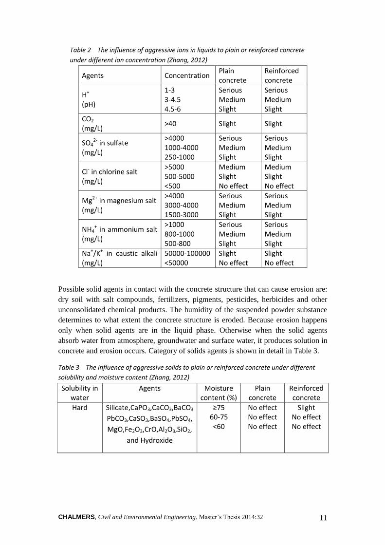
The Yellow River flows from west to east and alluvial plains are generated on the
both sides of the bridge as it is shown in Figure 15. On the north side of the river,
there is broadened flood detection area, which has a width of 4 km. The plain on the
Figure 11 In 2008, CFRP was pasted to the
roof and diaphragm in order to control
cracks.
Figure 13 The Jinan Yellow River
Highway Bridge is located in north
of Jinan, and it combines the State
Road of 104 and 220.
Figure 14 The Bridge lies at the downstream
of Yellow River as it can be seen at the red dot.
CHALMERS, Civil and Environmental Engineering, Master’s Thesis 2014:32 29
south of the river has relatively low terrain. It is flat and open, which is mostly used as
farmland. Part of the area is made into artificial ponds and ditches. The Queshan
Reservoirs locates in the west of the bridge.
Figure 15 The Yellow River flows from west to east. And the Queshan Reservoirs locates in the west of the bridge.
4.4 Hydrogeological description
The bridge site area is covered by Quaternary strata, mainly alluvial sediments. The
bridge site engineering geological strata mainly consist of the Quaternary fluvial clay,
which is mixed with silty clay, fine sand, medium sand, thin layers of clay and lenses
see Figure 16. The layer of silty clay is relatively impermeable compared to other
layers of aquitard or permeable layers (Li, 2005). Piles lie in the weathered rock
layers and this gives small settlements of the bridge.
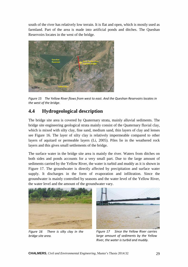
The surface water in the bridge site area is mainly the river. Waters from ditches on
both sides and ponds accounts for a very small part. Due to the large amount of
sediments carried by the Yellow River, the water is turbid and muddy as it is shown in
Figure 17. The groundwater is directly affected by precipitation and surface water
supply. It discharges in the form of evaporation and infiltration. Since the
groundwater is mainly controlled by seasons and the water level of the Yellow River,
the water level and the amount of the groundwater vary.
Figure 16 There is silty clay in the bridge site area.
Figure 17 Since the Yellow River carries large amount of sediments by the Yellow River, the water is turbid and muddy.

CHALMERS, Civil and Environmental Engineering, Master’s Thesis 2014:32 30
4.5 Meteorological characteristics
The bridge site belongs to the warm temperate zone semi-humid monsoon climate
zone. It has four distinctive seasons and obviously wet and dry seasons. Summer is
hot and rainy; while winter is cold and dry. Annual precipitation is between 650 mm
and 700 mm, which concentrate in June to September (Li, 2005). Rainfall is also rich
or poor among every year, thus droughts and floods often occur. Annual average
temperature is above 14oC with frost-free period of 250 days. According to the
China’s meteorological administration, the lowest temperature appears in January
with the average lowest temperature of -4oC during year 1997 to 2006 see Figure 18
(CMA, 2014). Usually from the middle of December, there is ice flow in the Yellow
River. The river is usually frozen up in beginning of January the following year. And
early spring thaw comes in the middle of February.
Figure 18 The green bar represents the average lowest temperature in January from
year 1997 to 2006, while the red bar represents the average highest temperature in
January (CMA, 2014).
4.6 Environmental classification based on concrete
durability
The road environment influencing structures is closely related to the durability of
concrete structure. As a matter of fact, durability of concrete structure is designed to
resolve the conflict between environmental action and structure's resistance.
According to design specifications domestic and abroad, the working environments of
the concrete structure are classified based on the erosion mechanism of environment
action and the erosion degree under different circumstances.
In China, based on the erosion mechanism, the category of environment composes of
normal environment, freeze-thaw environment, marine chloride environment, other
chloride environment such as deicing salt and chemical corrosion environment see

CHALMERS, Civil and Environmental Engineering, Master’s Thesis 2014:32 31
Table 5 (Wu, 2012). Different levels of environmental action are further divided in
Table 6.
By considering the surrounding environment of the Jinan Yellow River Highway
Bridge, the bridge is assumed belonging to level I-B. This means that the bridge is in
a normal environment and suffers from mild environmental actions. The damage from
external environment is mainly the reinforcement corrosion of protective layer caused
by concrete carbonation. Level II, which is the freeze-thaw environment, has also
been considered when the environmental classification has been made. This is
because according to local meteorological information, the bridge suffers from freeze-
thaw damage from December to next February. However, due to the lack of level II-B
(level II-B cannot be found in Table 6), the category of environment for the Yellow
River Highway Bridge falls to level I-B.
Table 5 The category of environment and their erosion mechanisms by considering the
concrete durability (Wu, 2012)
Category of environment Erosion mechanism
I Normal environment Reinforcement corrosion of protective layer caused by concrete carbonation
II Freeze-thaw environment Concrete damage caused by repeated freeze-thaw
III Marine chloride environment
Reinforcement corrosion caused by chloride
IV Other chloride environment ( deicing salt)
Reinforcement corrosion caused by chloride
V Chemical corrosion environment
Concrete corrosion caused by sulphates or other chemicals
Table 6 Different levels of environmental actions and the category of environment (Wu,
2012)
Level of environmental
action Category of environment
A B C D E F
Slight Mild Medium Serious Very serious
Extremely serious
Normal environment I-A I-B I-C - - -
Freeze-thaw environment
- - II-C II-D II-E -
Marine chloride environment
- - III-C III-D III-E III-F
Other chloride environment such as deicing salt
- - IV-C IV-D IV-E -
Chemical corrosion environment
- - V-C V-D V-E -

CHALMERS, Civil and Environmental Engineering, Master’s Thesis 2014:32 32
5 METHOD AND MEASUREMENT
Based on background description and environmental analysis of Jinan Yellow River
Highway Bridge, the concrete structure of the bridge mainly suffers from concrete
carbonation, which can cause reinforcement corrosion in the protective layer of the
steel bars. The box girder in the south side-span and south part of mid-span were
chosen for inspection. Preliminary visual inspection was made in order to detect the
types of damages on the surface of reinforced concrete structures and evaluate the
current conditions of the concrete. Then non-destructive test in terms of concrete
carbonation and corrosion of reinforced bar was carried out.
The chamber in the main girder is composed of diaphragm, roof, floor, straight web
and inclined web. Every component inside the chamber was inspected. The upstream
side of the chamber is the right chamber and is named with the letter R. The
downstream side of the chamber is the left chamber and is named with the letter L.
The middle chamber is in the middle of the girder and is named with letter M. The
number of the chamber is based on the number of the diaphragm. For example, the
upstream chamber between diaphragm 5# and 6# is named as R-5#. The number of
the diaphragm starts from 0# to 65# from south to north. Diaphragm 0# is the first
diaphragm at the south auxiliary pier in the anchor span. Diaphragm 65# is at the
middle of mid-span. Inspections in the south part of main girder start from diaphragm
11# at the south anchor pier to the diaphragm 65# at the middle of mid-span see
Figure 19.
Figure 19 The number of the diaphragm starts from 0# to 65# from south to north. And
the inspections start from diaphragm 11# at the south anchor pier to the diaphragm 65#
at the middle of mid-span.

CHALMERS, Civil and Environmental Engineering, Master’s Thesis 2014:32 33
5.1 Visual inspection
The concrete damage detection is mainly based on the visual inspection. Visual
inspection was made inside the upstream and downstream chambers in the main
girder. Tape, chalk, hammer, camera, crack width gauge, and laser rangefinder were
used, see Table 7. If there is problem with steel bars corrosion, concrete surface
defects, or concrete seepage, colour chalk was used to mark the damage and the range
of damage. Cracks may indicate lack of structural bearing capacity. Large cracks are
unfavourable since they can lead to reinforcement corrosion and reduce the durability
of concrete structures. If there are cracks on the surface of the concrete, the
distribution, location, strikes of the cracks need to be marked. For the more serious
cracks, rules and crack width gauge was used to measure the crack length and width.
Photos were taken for the typical damages. Table 8 shows the detailed visual
inspection items.
Table 7 Tools and devices for visual inspection
Devices Model Application Comment
Tape - Distance measurement -
Chalk - Mark -
Hammer - Concrete quality control -
Crack width gauge DJCK-2 Crack width measurement Figure 20
Camera - Taking photos -
Table 8 Detailed visual inspection items
Visual inspection Detailed inspections
Surface damage Concrete damage: Voids and pits, defects, flaking, seepage
Steel bars: Exposure of reinforcement, corrosion
Cracks Longitudinal cracks, temperature crack, Cracks due to concrete shrinkage, Cracks due to structure stress
Measuring the crack length, crack width, Crack depth that exceeds the limit
The preliminary inspection gives an
overview of the current conditions of the
reinforced concrete. After the visual
inspection, the reasons of concrete
damages and the degree of corrosion
should be evaluated.
Figure 20 Crack width gauge is used to
measure the crack width
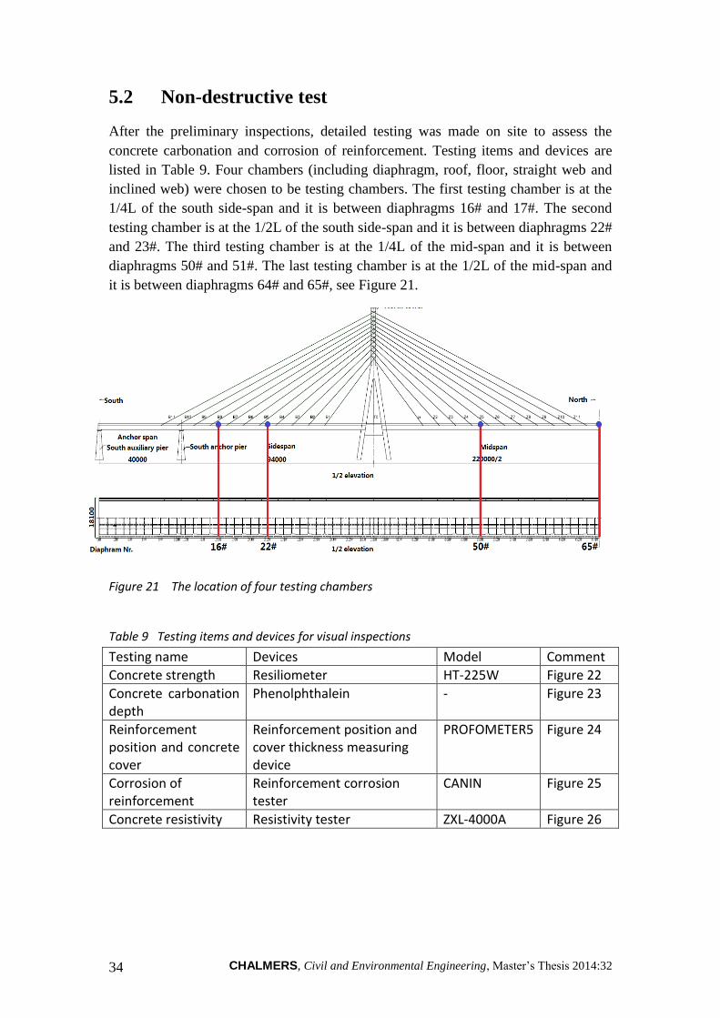
CHALMERS, Civil and Environmental Engineering, Master’s Thesis 2014:32 34
5.2 Non-destructive test
After the preliminary inspections, detailed testing was made on site to assess the
concrete carbonation and corrosion of reinforcement. Testing items and devices are
listed in Table 9. Four chambers (including diaphragm, roof, floor, straight web and
inclined web) were chosen to be testing chambers. The first testing chamber is at the
1/4L of the south side-span and it is between diaphragms 16# and 17#. The second
testing chamber is at the 1/2L of the south side-span and it is between diaphragms 22#
and 23#. The third testing chamber is at the 1/4L of the mid-span and it is between
diaphragms 50# and 51#. The last testing chamber is at the 1/2L of the mid-span and
it is between diaphragms 64# and 65#, see Figure 21.
Figure 21 The location of four testing chambers
Table 9 Testing items and devices for visual inspections
Testing name Devices Model Comment
Concrete strength Resiliometer HT-225W Figure 22
Concrete carbonation depth
Phenolphthalein - Figure 23
Reinforcement position and concrete cover
Reinforcement position and cover thickness measuring device
PROFOMETER5 Figure 24
Corrosion of reinforcement
Reinforcement corrosion tester
CANIN Figure 25
Concrete resistivity Resistivity tester ZXL-4000A Figure 26

CHALMERS, Civil and Environmental Engineering, Master’s Thesis 2014:32 35
Figure 22 Resiliometer for concrete
strength measurement
Figure 23 Phenolphthalein for concrete
carbonation depth measurement
Figure 24 Reinforcement position and
cover thickness measuring device
Figure 25 Reinforcement corrosion
tester
Figure 26 Resistivity tester for concrete
resistivity measurement

CHALMERS, Civil and Environmental Engineering, Master’s Thesis 2014:32 36
The strength of the concrete is measured by the resiliometer on site. The rebound area
on the concrete is 15 cm × 15 cm square. For every test, 10 rebound areas were tested
in order to determine the concrete strength. For each rebound area, there were 16
measurement points. To get the average rebound values, three maximum and three
minimum rebound values were removed from the measured 16 measurement points.
According to "Technical specification of compressive strength of concrete
measurement by the rebound method", the rebound value needs to be corrected. By
considering the influence of non-horizontal direction and different angles in testing
planes, estimation values of the concrete strength were calculated according to
Equation (9).
(9)
where Rm= estimation value of average concrete strength, Rmα= average concrete
strength measured in non-horizontal direction, Raα= corrected concrete strength
measured in angle α.
Estimation value of strength uniformity coefficient Kbt and average strength
uniformity coefficient Kbm were also calculated. They reflect the degree of variation in
concrete strength compared with the average concrete strength, see Equations (10)
and (11).
R
RK itbt
(10)
R
RK imbm
(11)
where Kbt= estimation value of strength uniformity coefficient, Kbm= average strength
uniformity coefficient, Rit= estimation value of average concrete strength, R= design
value of concrete strength, Rim= conversion value of average concrete strength, which
was derived from the estimation value of average concrete strength corrected by
considering the carbonation depth.
Concrete carbonation depth was measured at the representative positions in the testing
areas. Three testing areas were selected in the 10 rebound areas to measure the
concrete carbonation depth. The average value for the carbonation depth was
calculated from the three testing areas. Phenolphthalein was used to find the boundary
between the carbonized concrete and normal concrete. Then the carbonation depth dm
was measured. Concrete carbonation depth was used to evaluate the reinforcement
corrosion by comparing the average carbonation depth to the average thickness of the
concrete cover.
When measuring the reinforcement position and the thickness of concrete cover,
totally 10 testing areas including diaphragm, roof, floor, straight web and inclined

CHALMERS, Civil and Environmental Engineering, Master’s Thesis 2014:32 37
web were chosen from the side-span and mid-span, respectively. 50 cm × 50 cm
squares were arranged in the testing areas. PROFOMETER 5 was used to see if the
steel bars are still in the designed position. The average thickness of concrete cover
was also obtained. Then the characteristic value of the thickness of concrete cover Dne
was calculated from Equations (12), (13) and (14). The ratio between the
characteristic value of the thickness of concrete cover and the design value of the
thickness of concrete cover was evaluated to determine the influence of concrete
cover to the durability of reinforced structures.
Dne KSDD (12)
n
D
D
n
i
ni
n
1
(13)
1
)()(1
22
n
DnD
S
n
i
nni
D
(14)
where = average thickness of concrete cover for n points, n= number of measuring
points, Dne= characteristic values of the thickness of concrete cover, = average
thickness of concrete cover, K= qualified determination coefficient, which can be
calculated from Table 10, SD= standard value of the thickness of concrete cover.
Table 10 The relationship between qualified determination coefficient and testing
points
n 10-15 16-24 ≥25
K 1.695 1.645 1.595
In order to evaluate the reinforcement corrosion, two testing zones in the side-span
and mid-span were selected. 80 cm × 80 cm square was arranged to find the potential
level, which reflects the likelihood of steel bars corrosion and corrosion activity. Then
the possibility of reinforcement corrosion was determined. The concrete resistivity
was also measured to see the rate of reinforcement corrosion.
For testing the chloride concentration in concrete, it was not measured this year. Data
from year 2008 was used to analyse the chloride ion ingress. And only the data within
the testing zones, that is, the chambers from diaphragm 11# to 65#, were selected.

CHALMERS, Civil and Environmental Engineering, Master’s Thesis 2014:32 38
6 RESULT
This chapter displays the result from visual inspection and non-destructive tests.
Preliminary visual inspection was done to detect the types of damages on the surface
of reinforced concrete structures and to evaluate the current conditions of the concrete.
In order to assess the concrete carbonation and corrosion of reinforced bar, non-
destructive tests was done.
6.1 Concrete damage by visual inspection
The roof, floor, both sides of the webs, and diaphragm in the chamber were inspected
in order to find damages on the surface of the concrete.
Generally, the roof which has been refurbished in 2008 is in a good condition since
the CFRP has not drop and there is no cracking of CFRP. However, the main problem
with the roof is the longitudinal cracks at some junctions between the roof and
diaphragm. Several longitudinal cracks appeared as L-shaped and extended to
diaphragm. Mostly, the crack width was between 0.05 - 0.15 mm and the length was
20 - 40 cm. And all the width of the cracks does not exceed the limit, which is 0.20
mm. Table 11 shows the description and numbers of cracks. Table 12 shows the major
damages on the concrete in the roof.
Table 11 There are totally 38 cracks on the roof of the testing chambers with the crack
width between 0.05 - 0.15 mm.
Types of crack
Description Total length/ number
Crack width exceeding the limit
Comment
Longitudinal crack
Crack width is between 0.05 - 0.15 mm. Crack length is between 20 - 40 cm.
810 cm/27 - Figure 27
L-shaped crack
Crack width is between 0.05 - 0.1 mm. Crack length is 40 cm.
440 cm/11 - Figure 28
Table 12 Major concrete damages are found in the roof of the testing chambers with no
serious damages.
Types of damage
Location Total area/number Comment
Concrete damage
Toothed plate at L-40, L-50, L-52, and R-47#
3200 cm2/5 -
Exposure of reinforcement
Toothed plate at L-52 and R-61#
1300 cm2/2 Figure 29
Seepage and Anchor head at the toothed 1800 cm2/1 Figure 30

CHALMERS, Civil and Environmental Engineering, Master’s Thesis 2014:32 39
bleaching plate at L-22#
Rusting of anchor head
Anchor head at the toothed plate at L-28, L-29#
1200 cm2/2 Figure 31
Cavity of concrete
Toothed plate at L-52, L-55, and L-58#
1425 cm2/3 -
Rusting of reserved prestressing pipe
Toothed plate at R29 and R-39#
9000 cm2/9 Figure 30
Figure 27 Longitudinal crack is found
in the roof of some testing chambers.
Figure 28 L-shaped crack is found in
the roof of some testing chambers.
Figure 29 Exposure of reinforcement is
found in the toothed plate at L-52#.
Figure 31 Rusting of anchor head is
found at the toothed plate at L-29#.
Figure 30 Seepage and bleaching is found in
anchor head at the toothed plate in L-22#.
Figure 32 Rusting of reserved prestressing
pipe is found in the toothed plate at R-29#.

CHALMERS, Civil and Environmental Engineering, Master’s Thesis 2014:32 40
From the inspection results, no damage was found in the floor in the chambers. This
means that the floor is in a good technical condition.
The webs are in a better overall condition although there were a few damages in the
webs. All the straight webs are in a very good condition since no problem has been
detected. For the inclined webs, several diagonal cracks were spotted in the left
chambers. Concrete damages such as voids and pits, exposure of reinforcing bars and
seepage with bleaching problems were also detected in the left chambers. Detailed
inspections are shown in Tables 13 and 14.
Table 13 There are totally 4 cracks on the inclined web of the testing chambers with the crack width between 0.05 - 0.1 mm.
Types of crack
Description Location Total length/ number
Crack width exceeding the limit
Comment
Diagonal crack
Crack width is between 0.05 - 0.1 mm. Crack length is between 80 - 150 cm.
L-19, L-58#
450 cm/4 - Figure 33
Table 14 Major concrete damages are found in the inclined web of the testing chambers with no serious damages.
Types of damage
Location Total area/number Comment
Voids and pits Inclined web at L-23# 1200 cm2/1 Figure 34
Exposure of reinforcement
Inclined web at L-17# 1800 cm2/1 Figure 35
Seepage and bleaching
Inclined web at L-17# 2000 cm2/1 -
Figure 33 Diagonal crack is found in
the inclined web at L-19#.
Figure 34 Voids and pits on concrete is
found in the inclined web at L-23#.

CHALMERS, Civil and Environmental Engineering, Master’s Thesis 2014:32 41
Figure 35 Exposure of reinforcement is found in the inclined web at L-17#.
The diaphragms are also in a good overall condition although there were also a few
damages in the diaphragm. The inspection results also show no serious damage in the
diaphragm. The main damage is the diagonal crack and U-shaped crack, which
appears around the manhole at some of the diaphragms. However, the crack width
does not exceed the limit. Detailed inspections are shown in Table 15 and Table 16.
Table 15 There are totally 9 cracks on the diaphragm of the testing chambers with the
crack width between 0.05 - 0.2 mm.
Types of crack
Description Location Total length/ number
Crack width exceeding the limit
Comment
Transverse crack
Crack width is 0.05 mm. Crack length is 100 cm.
L-34# 100 cm/1 - Figure 36
Diagonal crack
Crack width is between 0.05 - 0.2 mm. Crack length is between 30 - 100 cm.
L-12, L-20, L-60#
280 cm/4 - Figure 37
L-shaped crack
Crack width is 0.05 mm. Crack length is 60 cm.
L-28# 60 cm/1 - Figure 38
U-shaped crack
Crack width is between 0.05 - 0.2 mm. Crack length is between 60 - 100 cm.
L-34, L-50, R-9#
240 cm/3 - -
Table 16 Major concrete damages are found in the diaphragm of the testing chambers
with no serious damages.
Types of damage
Location Total area/number Comment
Voids and pits L-61# 300 cm2/1 -
Exposure of reinforcement
L-19# 800 cm2/1 Figure 39
Seepage and bleaching
L-51# 100 cm2/1 -

CHALMERS, Civil and Environmental Engineering, Master’s Thesis 2014:32 42
6.2 Concrete strength and carbonation depth
Based on the concrete strength measurement, it can be seen that for the most part of
the concrete, they have the strength larger than the designed strength, see Table 17.
Only three values didn’t reach the designed values. When evaluating the strength
condition, strength uniformity coefficients Kbt and Kbm were used. It is shown that
most of the concrete has a very good strength conditions with the condition levels 1
and 2. Concrete in two testing zones has a relatively poor strength conditions with the
condition level 3, which means the concrete fails to meet the requirement according to
the strength uniformity coefficients. And only one testing result shows a very poor
strength condition with the condition level 5, which means the concrete is in danger.
In regard to the concrete carbonation depth, the values vary from 0.5 mm to 5.0 mm.
And they are far less than the thickness of concrete cover which has a designed value
of 37.5 mm, implying that the concrete is slightly suffered from carbonation. For
normal Portland cement concrete, carbonation will slightly increase the strength due
to the filling of pores. However, the result shows that for some testing zones the larger
Figure 36 Transverse crack is found in
the diaphragm at L-34#.
Figure 37 Diagonal crack is found in the
diaphragm at L-12#.
Figure 38 L-shaped crack is found in
diaphragm at L-28#.
Figure 39 Exposure of reinforcement is
found in diaphragm L-19#.

CHALMERS, Civil and Environmental Engineering, Master’s Thesis 2014:32 43
the carbonation depth was; the smaller the estimation value of concrete strength, and
the lower the strength of concrete. Probably carbonation reduced the hardness of
concrete surface, resulting in a lower rebound value when using the resiliometer.
Table 17 Result of concrete strength and carbonation depth in testing chambers
Testing zones
(MPa)
SD
(MPa)
Rmin.
(MPa)
dm
(mm)
Rm
(MPa)
R
(MPa) Kbt Kbm
Strength
Condition
Diaphragm 16# 71.4 5.9 48.1 1.0 61.6 40 1.54 1.20 1
Roof (diaphragm 16#-17#) 59.9 7.4 48.5 4.0 47.7 50 0.95 0.97 2
Str. web (diaphragm 16#-
17#) 75.8 5.4 51.9 1.0 66.9 50 1.34 1.04 1
Inc. web (diaphragm 16#-
17#) 53.2 4.4 41.4 4.0 46.0 50 0.92 0.83 5
Diaphragm 22# 75.1 2.3 54.2 1.0 71.4 40 1.79 1.36 1
Roof (diaphragm 22#-23#) 73.1 6.5 54.4 4.0 62.5 50 1.25 1.09 1
Str. web (diaphragm 22#-
23#) 77.9 4.1 54.0 1.0 71.1 50 1.42 1.08 1
Inc. web (diaphragm 22#-
23#) 68.6 5.6 47.6 5.0 59.5 50 1.19 0.95 2
Diaphragm 50# 56.2 12.6 40.8 1.0 35.4 40 0.89 1.02 3
Roof (diaphragm 50#-51#) 71.1 4.9 54.8 1.0 63.1 50 1.26 1.10 1
Floor (diaphragm 50#-51#) 81.5 8.0 56.4 1.0 68.3 50 1.37 1.13 1
Str. web (diaphragm 50#-
51#) 73.4 4.0 52.9 1.0 66.7 50 1.33 1.06 1
Inc. web (diaphragm 50#-
51#) 94.5 5.9 85.2 0.5 84.7 50 1.69 1.70 1
Diaphragm 65# 66.4 5.4 49.7 1.0 57.6 40 1.44 1.24 1
Roof (diaphragm 64#-65#) 69.0 6.4 51.4 3.0 58.3 50 1.17 1.03 1
Floor (diaphragm 64#-65#) 58.3 5.0 50.7 3.0 50.1 50 1.00 1.01 1

CHALMERS, Civil and Environmental Engineering, Master’s Thesis 2014:32 44
Testing zones
(MPa)
SD
(MPa)
Rmin.
(MPa)
dm
(mm)
Rm
(MPa)
R
(MPa) Kbt Kbm
Strength
Condition
Str. web (diaphragm 64#-
65#) 69.7 6.2 49 1.0 59.5 50 1.19 0.98 2
Inc. web (diaphragm 64#-
65#) 80.5 9.1 47 1.0 65.6 50 1.31 0.94 3
6.3 Reinforcement position and concrete cover
According to the measurement, half of the concrete cover on the reinforcement has a
smaller thickness compared with the designed value of 37.5 mm, see Table 18. The
measured minimum thickness of the protective layer is as low as 22.3 mm. Based on
the influence of the thickness of steel protective layer to the durability criteria, six of
the testing zones shows the concrete cover criterion of 5. This means that the
reinforced bars are very likely to lose alkaline protection and suffer from corrosion.
The result from one testing zone shows the criterion of 4, which means that it will
have a great impact on the durability of reinforced concrete. Two testing zone shows
the criterion of 3, which means that the durability may be influenced by the concrete
cover.
Table 18 Result of concrete cover in testing chambers
Testing zones
(mm)
SD
(mm)
Dne
(mm)
Dnd
(mm) Dne/ Dnd Comment
Diaphragm 16# 42.2 14.1 18.3 37.5 0.49 5
Roof (diaphragm 16#-17#) 43.7 13.0 21.7 37.5 0.58 5
Floor (diaphragm 16#-17#) 31.4 6.2 20.9 37.5 0.78 3
Str. web (diaphragm 16#-17#) 28.0 9.6 11.8 37.5 0.31 5
Inc. web (diaphragm 16#-17#) 50.3 12.9 28.4 37.5 0.76 3
Diaphragm 65# 47.9 5.3 38.8 37.5 1.04 1
Roof (diaphragm 64#-65#) 43.7 10.8 25.4 37.5 0.68 4
Floor (diaphragm 64#-65#) 23.6 8.6 9.1 37.5 0.24 5
Str. web (diaphragm 64#-65#) 31.0 11.8 10.9 37.5 0.29 5
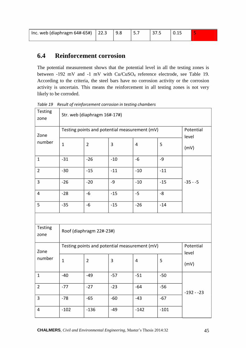
CHALMERS, Civil and Environmental Engineering, Master’s Thesis 2014:32 45
Inc. web (diaphragm 64#-65#) 22.3 9.8 5.7 37.5 0.15 5
6.4 Reinforcement corrosion
The potential measurement shows that the potential level in all the testing zones is
between -192 mV and -1 mV with Cu/CuSO4 reference electrode, see Table 19.
According to the criteria, the steel bars have no corrosion activity or the corrosion
activity is uncertain. This means the reinforcement in all testing zones is not very
likely to be corroded.
Table 19 Result of reinforcement corrosion in testing chambers
Testing
zone Str. web (diaphragm 16#-17#)
Zone
number
Testing points and potential measurement (mV) Potential
level
(mV) 1 2 3 4 5
1 -31 -26 -10 -6 -9
-35 - -5
2 -30 -15 -11 -10 -11
3 -26 -20 -9 -10 -15
4 -28 -6 -15 -5 -8
5 -35 -6 -15 -26 -14
Testing
zone Roof (diaphragm 22#-23#)
Zone
number
Testing points and potential measurement (mV) Potential
level
(mV) 1 2 3 4 5
1 -40 -49 -57 -51 -50
-192 - -23 2 -77 -27 -23 -64 -56
3 -78 -65 -60 -43 -67
4 -102 -136 -49 -142 -101

CHALMERS, Civil and Environmental Engineering, Master’s Thesis 2014:32 46
5 -80 -143 -104 -95 -192
Testing
zone Inc. web (diaphragm 50#-51#)
Zone
number
Testing points and potential measurement (mV) Potential
level
(mV) 1 2 3 4 5
1 -187 -135 -84 -25 -151
-187 - -25
2 -145 -78 -175 -75 -169
3 -144 -85 -72 -71 -79
4 -68 -62 -67 -72 -82
5 -72 -145 -149 -171 -169
Testing
zone Inc. web (diaphragm 64#-65#)
Zone
number
Testing points and potential measurement (mV) Potential
level
(mV) 1 2 3 4 5
1 -46 -120 -12 -5 -1
-120 - -1
2 -64 -2 -12 -14 -7
3 -31 -11 -2 -14 -7
4 -77 -10 -9 -38 -17
5 -63 -10 -71 -35 -19
6.5 Concrete resistivity
The resistivity measurement shows that the concrete resistivity in all the testing zones
is between 10330 and 19850 Ω·cm, see Table 20. According to the criteria, the rate of
corrosion of steel bars is very slow.
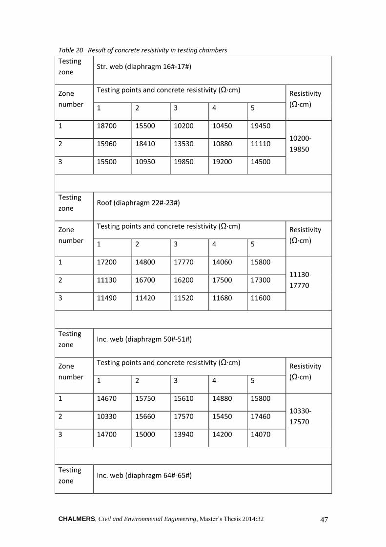
CHALMERS, Civil and Environmental Engineering, Master’s Thesis 2014:32 47
Table 20 Result of concrete resistivity in testing chambers
Testing
zone Str. web (diaphragm 16#-17#)
Zone
number
Testing points and concrete resistivity (Ω·cm) Resistivity
(Ω·cm) 1 2 3 4 5
1 18700 15500 10200 10450 19450
10200-
19850 2 15960 18410 13530 10880 11110
3 15500 10950 19850 19200 14500
Testing
zone Roof (diaphragm 22#-23#)
Zone
number
Testing points and concrete resistivity (Ω·cm) Resistivity
(Ω·cm) 1 2 3 4 5
1 17200 14800 17770 14060 15800
11130-
17770 2 11130 16700 16200 17500 17300
3 11490 11420 11520 11680 11600
Testing
zone Inc. web (diaphragm 50#-51#)
Zone
number
Testing points and concrete resistivity (Ω·cm) Resistivity
(Ω·cm) 1 2 3 4 5
1 14670 15750 15610 14880 15800
10330-
17570 2 10330 15660 17570 15450 17460
3 14700 15000 13940 14200 14070
Testing
zone Inc. web (diaphragm 64#-65#)

CHALMERS, Civil and Environmental Engineering, Master’s Thesis 2014:32 48
Zone
number
Testing points and concrete resistivity (Ω·cm) Resistivity
(Ω·cm) 1 2 3 4 5
1 14260 13450 14250 14850 11950
11780-
16620 2 11780 12800 14210 13700 13400
3 14740 16620 13510 13310 14910
6.6 Chloride concentration in concrete
Measurement data from year 2008 was used to analyse the impact of chloride ion
ingress to the reinforcement corrosion. As it is shown in Table 21, the chloride ion
concentration in all testing zones is between 0.15% and 0.4% by weight of cement,
which belongs to the criterion level 2. This means that it is uncertain about the
corrosion of steel bars due to chloride ion.
Table 21 Result of chloride concentration in concrete
Location Chloride
concentration (%) Criteria
Roof (diaphragm 13#-14#) 0.23 2
Str. web (diaphragm 13#-14#) 0.21 2
Floor (diaphragm 64#-65#) 0.32 2
Inc. web (diaphragm 52#-53#) 0.25 2
6.7 Summary
According to the visual inspection, the concrete in the testing chambers is generally in
a good condition. The roof which has been already refurbished by CFRP has few
problems with cracking and the crack width does not exceed the limit. However slight
concrete damages have been detected, such as concrete damage, exposure of
reinforcement and rusting of anchor head. There was no damage in the floor in the
chamber. There were few damages in the webs such as cracks, voids and pits in
concrete and water seepage. There was no serious damage in the diaphragm except for
some cracks and slight concrete damages.
The results from non-destructive tests show that most part of the concrete in testing
zones has a very good strength conditions. The thickness of carbonation depth is far
less than the designed value of concrete cover though the concrete suffers slightly

CHALMERS, Civil and Environmental Engineering, Master’s Thesis 2014:32 49
from carbonation. In regard to the concrete cover, the durability of the reinforcement
can be influenced by the concrete cover. Half reinforced bars in testing zones are very
likely to lose alkaline protection and suffer from corrosion. Fortunately, the potential
measurement shows that the bars have no corrosion activity or the corrosion activity is
uncertain. This means the reinforcement in all testing zones is not likely to be
corroded. The resistivity measurement shows that if the steel bar has been corroded,
the rate will be very slow.

CHALMERS, Civil and Environmental Engineering, Master’s Thesis 2014:32 50
7 DISCUSSION AND SUGGESTIONS
In this chapter the result presented above will be discussed and some suggestions will
be given. According to the measurement, most of the testing chambers in Jinan
Yellow River Highway Bridge are in a good technical condition, except for issues
with inadequate thickness of concrete cover, some slight concrete damages, and
cracks.
It is detected that almost half of the concrete cover on the reinforcement has a smaller
thickness compared to the designed value of 37.5 mm, which means that the concrete
cover may probably have an impact on the durability of reinforced concrete according
to the criteria. Generally, concrete cover is used to protect the reinforcement from
corrosion. Inadequate cover thickness may lead to reinforcement corrosion.
Fortunately the results from the reinforcement corrosion test shows that steel bars
have no corrosion activity or the corrosion activity is uncertain, which means that the
reinforcement is to a large extent, in a good condition and not very likely to be
corroded. However, it is recommended that cement mortar or concrete that has a
higher grade of strength than the original concrete could be pasted for safety’s sake.
Some slight concrete damages are found in some chambers. Concrete surface
damages are mainly the voids and pits, concrete damage, and exposure of
reinforcement. Voids and pits is the most common damage and it is owing to the
poor-compacting during concrete casting. Minor and slight pitted surface can be
easily patched by using polymer cement mortar followed by scraping and wiping
concrete surface. For more severe concrete damages such as stripping, concrete
damage, or concrete absent, damaged concrete should be removed until the surface of
fresh concrete can be seen. Then acrylic emulsion mortar can be used to mix with
proper coarse aggregates and patched onto the clean surface. Finally, the surface
should be scraped and wiped. For the exposure of reinforcement, all the loose
concrete should be removed by cutting or chiselling. Then acetones or alcohol is used
to clean the inner surface of the trenches. Finally, acrylic emulsion mortar is used to
seal the cuttings.
All the cracks inspected have a crack width less than 0.20 mm. According to criteria,
crack with the width less than 0.20 mm will not cause corrosion of the reinforcement.
This optimistic result is largely attributed to the pasting of CFRP on the roof and steel
plates on the webs in year 2008. However, in order to improve the durability of
reinforced concrete structures, the cracks could be sealed by polymer mortar. Then a
smooth and uniform surface could be achieved with no cracking or shedding.
The chloride concentration in concrete, which was measured in year 2008, shows that
it is uncertain about the corrosion of steel bars due to chloride ion. This means that it
is likely for the bridge to be influenced by the ingress of chloride ion, such as deicing
salts used in the winter. Since six years have passed, the current concentration of
chloride in concrete is unknown. Therefore it is highly recommended to make the

CHALMERS, Civil and Environmental Engineering, Master’s Thesis 2014:32 51
measurement again in order to make sure if the chloride ion has an influence on the
reinforced concrete or not.
The environmental classification in terms of concrete durability is based on single
environmental action and erosion mechanism. However, the natural environment is
often affected by a combined effort of different environmental factors. Therefore, this
environmental classification cannot reflect the environmental influence on the
structure in a good way. By considering the surrounding environment of the Jinan
Yellow River Highway Bridge, the bridge is assumed belonging to level I-B. That
means that the bridge is in a normal environment and suffers from mild environmental
actions such as carbonation of concrete. This assumption is a little conservative since
the bridge may suffer from freeze-thaw damage from December to next February.
However, it is considered that the influence of freeze-thaw cycles will not be that
severe because the average lowest temperature in January is only -4 o
C based on the
local meteorological information. It would be interesting to make further
investigations to see if how the freeze-thaw cycles influence the reinforced concrete
structures on the bridge.

CHALMERS, Civil and Environmental Engineering, Master’s Thesis 2014:32 52
8 CONCLUSIONS
Based on the literature study and the results from the visual inspections and non-
destructive tests, the following conclusions can be drawn.
Most of the testing chambers in Jinan Yellow River Highway Bridge are in a good
technical condition.
The concrete suffers slightly from carbonation but the thickness of carbonation
depth is far less than the designed value of concrete cover.
The reinforcement in all testing zones is not likely to be corroded.
However in some testing chambers, there are problems with inadequate thickness of
concrete cover, slight concrete damages, and cracks. In order to improve the durability
of the reinforced concrete structures on the bridge, it is suggested that these problems
can be treated by pasting cement mortar or acrylic emulsion mortar, which is also for
safety consideration.

CHALMERS, Civil and Environmental Engineering, Master’s Thesis 2014:32 53
9 REFERENCES
Broadcaster, J., 2012. News in progress. [Online] Available at:
http://www.ijntv.cn/news/folder21/folder125/2012/06/2012-06-09110054.html
[Accessed 11 June 2014].
Chi, P., Liang, Y. & Yu, S., 2001. Technical Methods to Improve the Durability of
Concrete. China Building Science Core Periodical, Augustus.
CMA, 2014. China Meteorological Administration. [Online] Available at:
http://www.cma.gov.cn/2011qxfw/2011qsjcx/ [Accessed 20 May 2014].
Deng, T., 2012. Research on the Influence of Reinforcement Corrrosion to Concrete
Durability. Master Thesis. Changsha, China: Changsha University.
Gao, F., 2013. Study on the Concrete Materials of Influencing Concrete Durability.
Cement and Concrete, (1003-8965(2013)01-0031-03).
Jin, H. & Jiang, C., 2011. Factors Influencing Freeze-thaw Damage and
Countermeasures. Science and Technology Innovation Herald, (1674-
098X(2011)11(a)-0046-01).
Kwan, A.K.H. & Wong, H.H.C., 2005. Durability of Reinforced Concrete Structures,
Theory vs Practice. Hong Kong, China: The University of Hong Kong.
Li, D., 2005. Substructure Construction Technology of Jinan Yellow River Bridge in
the Part of Beijing-Shanghai High-speed Railway. Master Thesis. Chengdu, China:
Southwest Jiaotong Univeristy Civil Engineering.
Li, H., 2012. Study on Durability Design and Critical Construction Technology for
Concrete Bridges. Master Thesis. Zhengzhou, China: Zhengzhou Univerisy.
Lin, C., 2013. Measures to Improve Durability of Reinforced Concrete Bridge in
Construction Stage. Science and Technology Guidance, December.
Liu, X., 2005. Research on Concrete Durability Technology. Tangshan, China: Jidong
Oilfield Construction Management Department.
Liu, H., 2013. Civil Engineering Material. 1st ed. Beijing, China: Machinery Industry
Press.
Lu, M., 1997. Recent Study and Research Directions of Concrete Durability. Industry
Construction, 27.
Lulu, B., Joerg, K. & David, J.C., 2001. Assessment of the Durability of Concrete
from Its Permeation Properties: A Review. Construction and Building Materials 15.
Neville, A.M., 1995. Properties of Concrete. 4th ed. England, UK: Longman Group
Limited.

CHALMERS, Civil and Environmental Engineering, Master’s Thesis 2014:32 54
Parrott, L.J., 1987. A Review of Carbonation in Reinforced Concrete, Cement and
Concrete Association. Slough, UK: Cement & Concrete Association of Great Britain.
Shandong Highway Engineering Consulting Company, 2008. Health Inspection and
Technical Evaluation of Jinan Yellow River Highway Bridge. Jinan, China: Shandong
Highway Engineering Consulting Company Civil Engineering, Tongji University.
Song, X., Xu, F. & Chen, R., 2009. The Inspection and Maintenance of Jinan Yellow
River Highway Bridge. Jinan, China: China Academic Journal Electronic Publishing
House.
Song, X., Xu, F. & Li, J., 2007. Health Monitoring System for Jinan Yellow River
Highway Bridge. Jinan, China: China Academic Journal Electronic Publishing House.
Tan, W., 2005. Factors Affecting the Durability of Concrete Structures and
Countermeasures. Beijing, China: Tsinghua University.
Vagelis, G.P., Costas, G.V. & Michael, N.F., 1991. Physical and Chemical
Characteristics Affecting the Durability of Concrete. ACI Material Journal, March.
Wang, Z., 2006. Life-cycle Analysis of Construction Project Based on the Durability
of Concrete. Shanghai, China: Tongji University.
Wu, H., 2012. Environment Classification Based on Concrete Durability of
Reinforced Concrete Structures. Ph.D. Thesis. Hangzhou, China: Zhejiang University
Civil Engineering.
Zhang, H., 2012. Research on Improving Structural Durability of Highway Concrete.
Master Thesis. Jinan, China: Shandong University.
Zhang, C., Yang, J., Re, S. & Wang, M., 2007. The Relationship between Concrete
Permeability and Durability and Methods to Improve the Impermeability. Concrete
Products, June.

CHALMERS, Civil and Environmental Engineering, Master’s Thesis 2014:32 55
10 APPENDIX
Table A-1 Concrete strength condition criteria (Liu, 2013)
Kbt Kbm Strength condition Criteria
≥ 0.95 ≥ 1.00 Very good 1
0.90 - 0.95 ≥ 0.95 Good 2
0.81 - 0.89 ≥ 0.90 Moderate 3
0.70 - 0.80 ≥ 0.85 Bad 4
≤ 0.70 < 0.84 Dangerous 5
Table A-2 The influence of concrete cover to reinforcement durability (Liu, 2013)
Dne/ Dnd Influence on durability Criteria
> 0.95 No influence 1
0.85 - 0.95 Slightly 2
0.70 - 0.85 Moderate 3
0.55 - 0.70 Great 4
< 0.55 Reinforcement is likely to be corroded. 5
Table A-3 Probability of reinforcement corrosion according to potential level test (Liu,
2013)
Potential level (mV) Reinforcement corrosion Criteria
0 - -200 No corrosion or uncertain corrosion
activity 1
-200 - -300 Probable corrosion 2
-300 - -400 Corrosion probability more than 90% 3
-400 - -500 Very likely to have corrosion 4
< -500 Corrosion occurs. 5

CHALMERS, Civil and Environmental Engineering, Master’s Thesis 2014:32 56
Table A-4 Speed for reinforcement corrosion according to resistivity (Liu, 2013)
Resistivity (Ώ·cm) Possible corrosion speed Criteria
> 20000 Very slow 1
15000-20000 Slow 2
10000-15000 Moderate 3
5000-10000 Fast 4
< 5000 Very fast 5
Table A-5 Probability of reinforcement corrosion due to chloride ion (Liu, 2013)
Concentration of
chloride ion in
cement (%)
Probability for reinforcement corrosion Criteria
< 0.15 Very little 1
0.15 - 0.4 Uncertain 2
0.4 - 0.7 Moderate 3
0.7 - 1.0 Sure 4
> 1.0 Already corroded 5