The S.S. Great Britain splice - seile.com
14
OIPEEC Round Table Conference - Bethlehem - August 2001 201 D. Sayenga*, R. Verreet** & I.M.L. Ridge*** ODN 0722 *AWRF, USA; **Wire Rope Technology Aachen, Germany; ***The University of Reading, UK The S.S. Great Britain splice Summary In 1838 when Isambard K. Brunel and Thomas Guppy set about designing the ship which was to become known as the S.S. Great Britain, Brunel seized upon the opportunity for technological advancement. In addition to the ship being by far the largest designed to that date, she incorporated screw propulsion, and additionally was amongst the first ships to be rigged with iron wire rope. The application of iron wire rope to an innovative project of such magnitude obviously played a highly influential role in the subsequent adoption of wire rope standing rigging for ships all over the world. The original wire rope rigging on the Great Britain was significant not only because of the ship's importance, but also because the wire rope itself was involved in litigation between two fledgling British wire rope manufacturers of the era. This paper discusses the background behind the use of iron wire rigging, and describes the finding and examination of a contemporary splice discovered on a visit to the Great Britain at her current home in Bristol. An investigation has been made into the construction and efficiency of the splice, the results of which are presented here. 1. Introduction During a trip to the UK in 1997, Roland Verreet (WRTA, Germany) and Donald Sayenga (AWRF, Lehigh Valley PA) visited the Great Britain at her dock in Bristol. When they inspected the ship, both men were astonished to find several examples of very old wire rope rigging displayed. At the time of the visit, no one on the site could provide much additional information about the exact age of the various rigging items. In the specific case of what appeared to be a main mast stay, Verreet and Sayenga carefully examined a loop splice unlike anything either of them had seen previously in the field of wire rope. Verreet became intrigued by the nature of the splice. Sayenga became intrigued by the history of the rigging. They resolved to combine their efforts to document whatever could be learned about the old rigging. They recruited Isabel Ridge (The University of Reading) to seek archival information about the history of the Great Britain. This paper is the result of that effort. 2. Isambard Kingdom Brunel and the Great Britain For three decades in Europe from 1800-1830, the rapid development of technology for mass production of wrought iron opened up possibilities for many engineering
Transcript of The S.S. Great Britain splice - seile.com

OIPEEC Round Table Conference - Bethlehem - August 2001
201
D. Sayenga*, R. Verreet** & I.M.L. Ridge*** ODN 0722 *AWRF, USA; **Wire Rope Technology Aachen, Germany;
***The University of Reading, UK
The S.S. Great Britain splice
Summary
In 1838 when Isambard K. Brunel and Thomas Guppy set about designing the ship which was to become known as the S.S. Great Britain, Brunel seized upon the opportunity for technological advancement. In addition to the ship being by far the largest designed to that date, she incorporated screw propulsion, and additionally was amongst the first ships to be rigged with iron wire rope. The application of iron wire rope to an innovative project of such magnitude obviously played a highly influential role in the subsequent adoption of wire rope standing rigging for ships all over the world. The original wire rope rigging on the Great Britain was significant not only because of the ship's importance, but also because the wire rope itself was involved in litigation between two fledgling British wire rope manufacturers of the era.
This paper discusses the background behind the use of iron wire rigging, and describes the finding and examination of a contemporary splice discovered on a visit to the Great Britain at her current home in Bristol. An investigation has been made into the construction and efficiency of the splice, the results of which are presented here.
1. Introduction
During a trip to the UK in 1997, Roland Verreet (WRTA, Germany) and Donald Sayenga (AWRF, Lehigh Valley PA) visited the Great Britain at her dock in Bristol.
When they inspected the ship, both men were astonished to find several examples of very old wire rope rigging displayed. At the time of the visit, no one on the site could provide much additional information about the exact age of the various rigging items. In the specific case of what appeared to be a main mast stay, Verreet and Sayenga carefully examined a loop splice unlike anything either of them had seen previously in the field of wire rope.
Verreet became intrigued by the nature of the splice. Sayenga became intrigued by the history of the rigging. They resolved to combine their efforts to document whatever could be learned about the old rigging. They recruited Isabel Ridge (The University of Reading) to seek archival information about the history of the Great Britain. This paper is the result of that effort.
2. Isambard Kingdom Brunel and the Great Britain
For three decades in Europe from 1800-1830, the rapid development of technology for mass production of wrought iron opened up possibilities for many engineering
Rope Terminations and Fittings
202
structures to be fabricated from the material, which had previously been prohibited either by quality, availability or cost.
Against this background, and following on from the success of the S.S. Great Western, Isambard Kingdom Brunel and Thomas Guppy were commissioned to design a sister ship. True to his pioneering character, Brunel saw this commission as an opportunity for technological advancement, and also true to his character, Brunel was not to be confined to advancement in one area, but in several at the same time (Vaughan, 1991).
Biographies of Brunel give a much fuller account of the achievements, scale and diversity of his career (Rolt, 1957 and Vaughan, 1991), but a brief discussion concerning the design and involvement with the Great Britain is made here as background to the subject of this paper, the design and manufacture of an eye splice in the rigging of the Great Britain.
Initial calculations had shown that for a ship of the size originally intended (2000 ton displacement), that wood was not strong enough to withstand the loads to which it would be subject in the harsh Atlantic Ocean. In October 1838, Brunel saw the paddle steamer Rainbow, an iron hulled boat. Inspired by this design, Brunel realised that iron was the answer to the strength problem.
Brunel and Guppy started work in earnest on the design of the hull of the ship which at that stage was known appropriately as “Mammoth”, in November 1838. Their final design was a combined paddle steamer/sailing ship, and had a displacement of over 3,500 tons. In this design Brunel and Guppy had no precedent to follow, typical iron hulled vessels of that time having displacements of about 600 tons or one sixth of what they were planning (Corlett, 1975, 26). By May 1840 construction work was well underway when by chance Brunel saw the S.S. Archimedes come into the docks at Bristol. The Archimedes was a screw propeller driven ship, and immediately Brunel saw the advantages of this method of propulsion for the Great Britain. Construction work was suspended for several months whilst trials were carried out to investigate the suitability of a screw propeller, and in December 1840 a resolution was passed by the controlling board adopting screw propulsion.
Having changed the means of propulsion, it was necessary to redesign the engines, since a screw propeller would have to turn at a faster rate that the originally designed paddle wheels. Following the untimely death of the original engine designer, Francis Humphreys, Brunel and Guppy designed the engine themselves.
Turning our attention to the rigging; in a description of the Great Britain published by Mechanics Magazine on September 10th, the author Hill (1842), observed:
“I understand it is the intention of the Directors to use wire standing rigging, which appears admirably adapted for the purpose from its being less in size, and therefore presenting less surface when under “bare poles”, from its being lighter than rope, strength for strength, from its greater durability - for if oxydation be prevented there seems to be no limit to it, and from its maintaining nearly a permanent length, and not requiring frequent “setting up” as is the case with rope, and probably it is more particularly applicable to iron vessels than wooden ones, from the rigidity of the former not requiring the elasticity that may be serviceable in the latter.”
(It should be noted that in this context “rope” refers to hemp (fibre) rope and “wire standing rigging” to iron wire rope.)
OIPEEC Round Table Conference - Bethlehem - August 2001
203
Later in the same article, Hill (1842) discussed a problem which would be encountered in the use of iron ships and rigging - that of lightning strikes.
“Mr. Snow Harris of Plymouth proposes to let in a slip of copper to the side of the masts, from the highest point of the main-top-mast… …Mr. Andrew Smith, of London, uses copper wire rope, from the same point aloft, but brought down by the sides of the shrouds and crosstrees”
Hill concluded with an assessment that he felt Smith's plan was better.
The ship was launched in 1843, only nine years after the successful introduction of stranded wire rope. At that time, perhaps a half-dozen rope makers in the British Isles had commenced the manufacture of wire ropes, and several ships had been rigged with the new iron rigging. Hence whilst not being a completely new application, the use of wire rope as standing rigging on the largest ship of its time can only have had a positive influence on the wider adoption of the material for that purpose.
In a report of the launch of the Great Britain (Anon., 1843) which took place on the 19th July 1843, we are told:
“… She has six masts, the highest of which is 74 feet above deck. She will carry about 1,700 square yards of canvass, and she will be rigged with wire ropes instead of ordinary ropes, manufactured by Messrs. R.S. Newall and Co. of Gateshead-on-Tyne…”
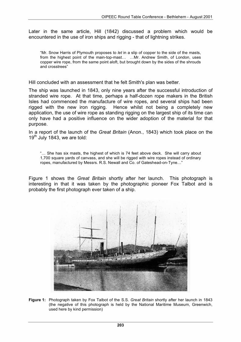
Figure 1 shows the Great Britain shortly after her launch. This photograph is interesting in that it was taken by the photographic pioneer Fox Talbot and is probably the first photograph ever taken of a ship.
Figure 1: Photograph taken by Fox Talbot of the S.S. Great Britain shortly after her launch in 1843 (the negative of this photograph is held by the National Maritime Museum, Greenwich, used here by kind permission)

Rope Terminations and Fittings
204
3. Smith vs. Newall
The original wire rope rigging on the S.S. Great Britain was significant not only because of the ship's importance, but also because the wire rope itself was involved in litigation between two fledgling British wire rope manufacturers of the era.
At that time, inventor Andrew Smith of London, who held several patents on wire rope (Woodcroft, no date), had accumulated more experience than any of the other English producers. Smith first experimented with wire ropes around 1827 for use as sash cords in connection with a metal shutter he had invented. He seems to have recognised at an early date that ship rigging presented a large potential market, and he obtained patents for several types of wire rope rigging (Smith, 1835 and 1836), see also Figure 2.
In one of his patents, sealed on 20th September, Smith (1839) specifically claimed the invention of a process for using conventional machinery to make ropes from lengths of malleable iron wire by “twisting them together by any of the machinery commonly used for rope making”. On the strength of this patent, in the early 1840's, Smith began to bring infringement lawsuits against others who were making wire ropes by use of conventional cordage machinery.
Figure 2: Andrew Smith's circular (no date) showing standing rigging methods
OIPEEC Round Table Conference - Bethlehem - August 2001
205
Meanwhile, two other groups of innovators (Gordon, Liddell & Newall and Heiman & Kuper) were actively pursuing the manufacture of wire ropes, no doubt inspired by the success of W. Albert's iron wire ropes in the Harz mining region. Gordon had undertaken part of his education at the Freiburg School of Mines in Germany, and occupied his vacation visiting Albert at the Clausthal Mines (Forestier-Walker, 1952, 26). It is reasonable to assume that Heiman & Kuper, coming from Germany, were also familiar with the work of Albert. Newall filed for a patent on the 17th August 1840 for “improvements in wire rope and machinery for making such a rope” (Newall, 1840). It is interesting to note that at that time, Andrew Smith petitioned against the patent being granted, but to no avail.
Newall had perceptively identified two key elements of good rope making:
“These were first the necessity of avoiding twist in the individual wires forming the strands, and secondly, the necessity of ensuring equal stress upon the individual wire and strands, which in turn, required that these components should be accurately held equidistant from their respective centres. This was achieved by forming the wires and strands around hemp cores properly maintained in position.” Forestier-Walker (1952).
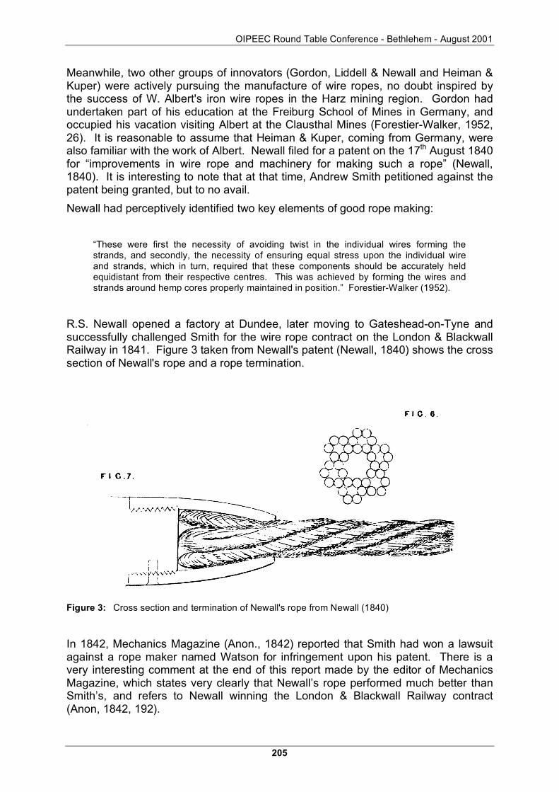
R.S. Newall opened a factory at Dundee, later moving to Gateshead-on-Tyne and successfully challenged Smith for the wire rope contract on the London & Blackwall Railway in 1841. Figure 3 taken from Newall's patent (Newall, 1840) shows the cross section of Newall's rope and a rope termination.
Figure 3: Cross section and termination of Newall's rope from Newall (1840)
In 1842, Mechanics Magazine (Anon., 1842) reported that Smith had won a lawsuit against a rope maker named Watson for infringement upon his patent. There is a very interesting comment at the end of this report made by the editor of Mechanics Magazine, which states very clearly that Newall’s rope performed much better than Smith’s, and refers to Newall winning the London & Blackwall Railway contract (Anon, 1842, 192).

Rope Terminations and Fittings
206
“…Some of the evidence for the plaintiff certainly is, on the face of it, of a most suspicious description… …We have always understood that Smith's wire rope, so far from answering the purpose on this line [London & Blackwall Railway] had proved a failure and that another sort patented by Mr. Newall, had been substituted for it… ED. M.M.”
One week later the same journal printed a letter from Smith stating openly that he would be bringing a similar patent infringement lawsuit against R.S. Newall (Smith, 1842). In another letter, this time to The Mining Journal, Smith (1844) declared:
“… As my name has, however, been frequently mentioned in reference to wire rope - the Richard Cobden and the Great Britain - I conceive that it would be an injustice to the public if I did not trouble you with an explanation. … …Mr. Guppy was the architect for the Great Britain and the Richard Cobden and Messrs. Newall and Co. fitted them with wire rope standing rigging. When the Richard Cobden was fitting out with Newall's rope my agents at Liverpool cautioned the builder, and also the owners, about the unseaman-like manner of fitting the rigging, and that the masts would go overboard the first breeze… …but there are legal proceedings pending against those foreigners Messrs. Hyman and Kuper, as well as Messrs. Newall and Co.”
Smith, however, was unable to enforce his patent against operators of the new machinery. He went bankrupt in 1849. The complete story of these events has been described by Forestier-Walker (1952) in his “History of the Wire Rope Manufacturers of Great Britain”.
4. Service and refits
The Great Britain went into service in late 1845 following trials at sea and final fitting. That winter, she was laid up for modifications, principally for the fitting of a new propeller, but also to allow improvements to the steam raising. Alterations were also made to her rig, probably to balance it so that the ship would handle better. One of the masts was removed, and iron wire rope was replaced with hemp. As Corlett (1975, 121) observed, this was probably to please the Captains Hosken and Claxton. It is not clear if all the iron rigging was replaced at this time or not.
The Great Britain left Liverpool on September 26th 1846, bound for New York, on what would have been her fifth double crossing of the Atlantic. Inexplicably, but thought to be owing to poor navigation (possibly caused by problems with the ship's compass being affected by the large iron hull), she ran aground in Dundrum Bay (Ireland), just to the west of the Isle of Man. This accident bankrupted the ship’s owners, the Great Western Steamship Co. who had greatly under-insured her.
Following salvage from Dundrum Bay, the Great Britain was sold in December 1850 to Gibbs & Co. who used her on the route between England and Australia, where gold had been newly discovered. In order to operate most effectively on the much longer voyage, the Great Britain was extensively modified. The engine was replaced with a smaller and more efficient one, and below deck passenger accommodation gave way to increased cargo space. Again the rigging was changed, the details of which may be found in Corlett (1975, 147), so that by 1852, only two of the masts were left as Brunel had designed them. It is not known if they still had the original wire rope rigging.
OIPEEC Round Table Conference - Bethlehem - August 2001
207
As a steam powered ship with auxiliary sail, and following the steam ship route (travelling via the Cape of Good Hope (Africa)), the Great Britain was not able to make the best time between England and Australia - in order to do this, she would have to be able to take advantage of the much stronger winds found by going around Cape Horn (South America). Hence in April 1853, Great Britain was again re-rigged, and became a three masted sailing ship with auxiliary steam power.
After service as a troop ship in the Crimean War (during 1855-1856), the Great Britain again underwent a significant refit. The refit which was undertaken over the winter 1856-1857 involved removing her entire rigging, and replacing it with one which was heavier and more substantial (Corlett, 1975, 159). Following this, the Great Britain completed many successful voyages between Liverpool and Melbourne, and was retired from service on that route in 1875.
In 1881 the Great Britain was sold to Victor Gibbs, who had trading interests with the west coasts of North and South America. The Great Britain was converted to a sailing ship and her engines removed to make way for cargo. The last voyage of the Great Britain was carrying coal from Cardiff to Panama. While sailing round Cape Horn during the winter of 1885-1886, parts of her masts were carried away in a severe gale. She put into the Falklands for shelter and repairs but a survey of the damage indicated she was beyond economic repair. The open hull, when condemned, offered an unusual opportunity as a floating warehouse.
From 1886 until 1933 she was used as a hulk to store wool just outside Port Stanley in the Falklands. Four years after finishing storage service, she was towed to nearby Sparrow Cove and scuttled.
Responding to the ideas proposed by Dr. Ewan Corlett, a British businessman named Jack Hayward agreed to underwrite the costs of bringing the ship back to Bristol where she had been launched in 1843. After considerable expenditure and volunteer effort, she arrived back in 1970, where she rests today, high and dry, in the same dry dock where her career began.
5. The Great Britain in Bristol today
In view of the extensive rigging changes described above, the remnants of old wire rope seen on the vessel today are very unlikely to be the original wire ropes. It is not possible to exactly document when and where the surviving pieces of rigging were made and installed, but it seems reasonable to assume that they date from after 1857 and before 1886.
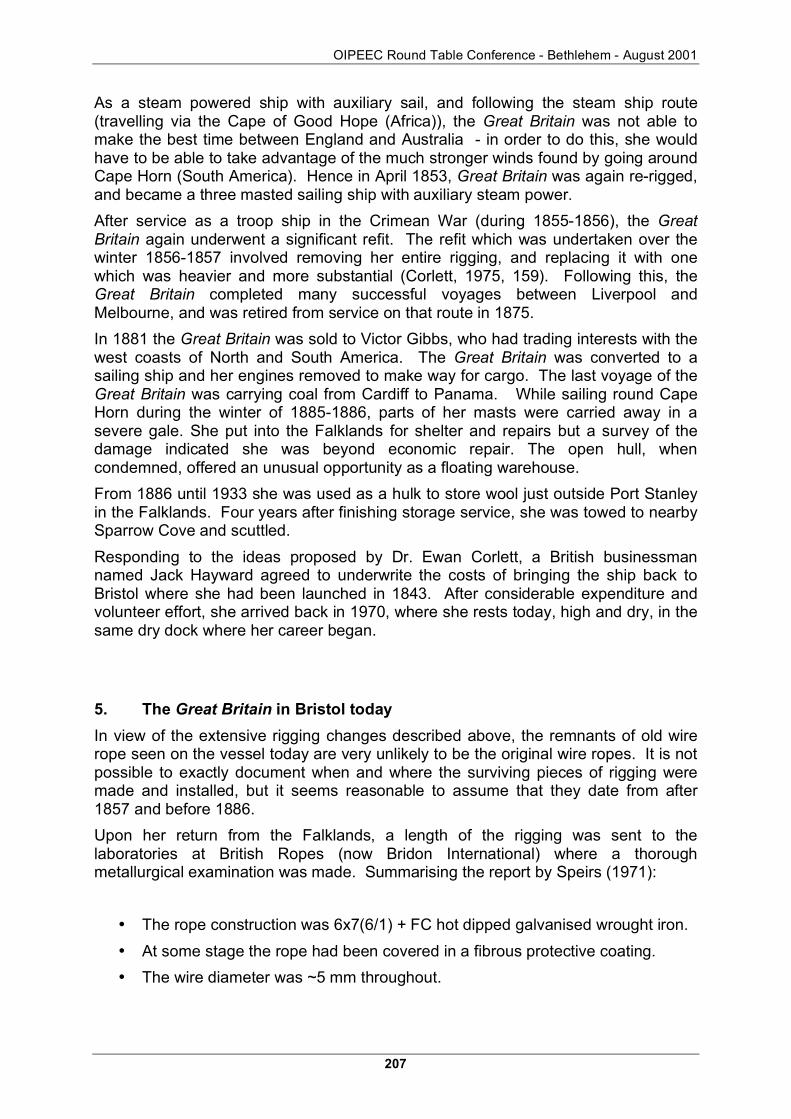
Upon her return from the Falklands, a length of the rigging was sent to the laboratories at British Ropes (now Bridon International) where a thorough metallurgical examination was made. Summarising the report by Speirs (1971):
• The rope construction was 6x7(6/1) + FC hot dipped galvanised wrought iron.
• At some stage the rope had been covered in a fibrous protective coating.
• The wire diameter was ~5 mm throughout.

Rope Terminations and Fittings
208
• The UBL was estimated at 35 - 40 kN based on strength tests on wires giving strength 40-50 N/mm2. The wrought iron composition was exceptionally high in carbon and inclusion content.
• On the inner wires there was evidence of galvanising - Speirs (1971) states that galvanising was not patented (and by his implication used) until 1855, however Andrew Smith mentions zinc coating in his patent of 1839 (Smith, 1839).
• A more compelling evidence of a later date is that Speirs (1971) considers that the wires were produced by drawing from continuously rolled rod owing to their length (it is not stated what their length is but circumstantial evidence would suggest at least 8 m) this method was introduced in 1860-1875 (Anon., 1957).
• Speirs (1971) concludes that the rope inspected was contemporary with the 1882 re-rigging.
From this the authors can only surmise the splice, which may or may not have been part of the standing rigging in the form of a main mast stay, was made no earlier than 1856 and no later than 1882.
6. Examination and reconstruction of the splice on the rigging
Donald Sayenga and Roland Verreet were not equipped to take measurements on their unexpected find, so they used modern technology to solve the problem: a camera and a cellular phone. They took photographs of the splice and a Nokia cellular phone lying right next to it (Figure 4). In this way they could later measure the rope diameter, the rope lay length and the splice dimensions on an enlargement of the photograph, using the cellular phone as a scale.
Figure 4: The Great Britain splice discovered at Bristol
On the basis of these geometrical data, a copy of the rope was made at Casar Drahtseilwerk Saar in Germany. Iron wire (as used on the original ropes) was not available, so steel wires of a relatively low tensile grade were used.

OIPEEC Round Table Conference - Bethlehem - August 2001
209
The rope, which is shown in section in Figure 5, had the following composition:
• 6 x 7(6/1) + Fibre Core
• Effective rope diameter 37.6 mm
• Wire diameter 4.1 mm
• The measured average wire tensile was 583 N/mm2.
Figure 5: Cross section of the 6x7(6/1) + FC rope
Based on the wire tensile strength, a rope breaking strength of 323.28 kN was calculated. DIN 15 020 states a spinning factor of 0.9 for 6x7 fibre core ropes. On the basis of this figure a minimum breaking strength of 290.95 kN was calculated.
The break test of the rope carried out at Casar showed an effective breaking strength of 309.30 kN. So the spinning factor was as high as 0.957!
But the main aim of the investigation was to remake the splice. It was very clear to the authors that the splice they had seen in Bristol had been made in a completely different way to which we would make a splice today: As in modern splices, a rope loop had been laid around a thimble, but the strand ends had not been stitched back into the live part of the rope. It looked as if every single strand had formed its own loop around the thimble, so that the six strand rope had six individually closed strand loops as an end connection.
The authors thought that the individual loops had been formed by splicing the wires of strand number 1 back into the live part of strand number 1, the wires of strand number 2 back into the live part of strand number 2 etc, and they discussed this procedure to the splicers who were assisting in the investigation. It turned out that it was impossible to make six individual loops of the same length using this method.
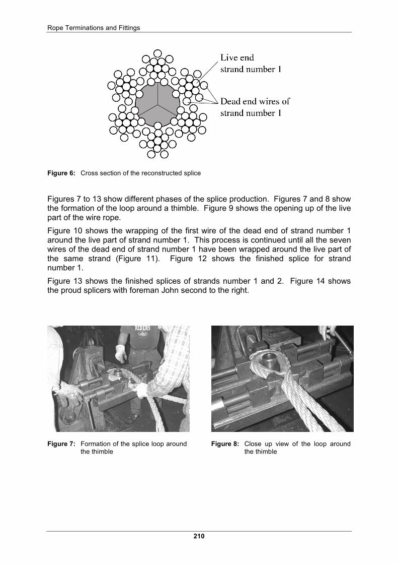
Mr. John, the foreman of the splicers analysed the photographs and came back with what turned out to be the correct explanation of the splicing procedure: The wires of every strand had not been spliced back into the same strand, they had simply been wrapped around it! Figure 6 shows the cross section of the rope in the splice zone.
Rope Terminations and Fittings
210
Figure 6: Cross section of the reconstructed splice
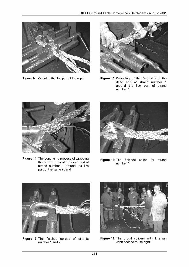
Figures 7 to 13 show different phases of the splice production. Figures 7 and 8 show the formation of the loop around a thimble. Figure 9 shows the opening up of the live part of the wire rope.
Figure 10 shows the wrapping of the first wire of the dead end of strand number 1 around the live part of strand number 1. This process is continued until all the seven wires of the dead end of strand number 1 have been wrapped around the live part of the same strand (Figure 11). Figure 12 shows the finished splice for strand number 1.
Figure 13 shows the finished splices of strands number 1 and 2. Figure 14 shows the proud splicers with foreman John second to the right.
Figure 7: Formation of the splice loop around the thimble
Figure 8: Close up view of the loop around the thimble
OIPEEC Round Table Conference - Bethlehem - August 2001
211
Figure 9: Opening the live part of the rope
Figure 11: The continuing process of wrapping the seven wires of the dead end of strand number 1 around the live part of the same strand
Figure 13: The finished splices of strands number 1 and 2
Figure 10: Wrapping of the first wire of the dead end of strand number 1 around the live part of strand number 1
Figure 12: The finished splice for strand number 1
Figure 14: The proud splicers with foreman John second to the right

Rope Terminations and Fittings
212
Figure 15: Comparison of the Great Britain splice discovered at Bristol (bottom) and the replica made during this study (top)
The finished splice is shown superimposed above the original splice in the top half of Figure 15. A comparison with the original splice below clearly shows their similarity, indicating that the correct procedures and dimensions have been used: that is that the rope was laid around a thimble, and then every single strand was brought back to itself. And the individual wires of each strand were wrapped around the same strand in the live line.
In total, 4 splices have been made. With every splice, the routine and the final product of the splicers improved.
One of the splices was subjected to a break test at Casar. The breaking strength of the splice was 303.50 kN, a figure only 1.9% below the breaking strength of the rope itself. The rope broke right at the transition area between the splice zone and the un-spliced live part of the rope. This result proved a great static efficiency of the SS Great Britain Splice.
Tension-tension test were prepared to also examine the splice's dynamic properties, but unfortunately the results could not be obtained in time for this paper.
7. Acknowledgements
The authors would like to acknowledge and thank Bridon Ropes for making available the results of a study on a length of wire rope from the Great Britain, and Casar Drahtseilwerk Saar for manufacturing and testing the rope and the splice.

OIPEEC Round Table Conference - Bethlehem - August 2001
213
8. References
Anon. (1842) Infringement of patent right - Nothern Circuit, Liverpool, August 10 Smith v Watson The Mechanics Magazine, Museum, Register, Journal and Gazette Vol. XXXVII No. 993 Saturday August 20th 1842, London, pages 189-190 and 191-192.
Anon. (1957) The making shaping and treating of steel United States Steel Corporation 1957, 675.
Corlett, E. (1975) The iron ship - the history and significance of Brunel's Great Britain Moonraker Press, Wiltshire.
DIN 15 020 Grundsätze für Seiltriebe Berechnung und Ausfürung (Lifting appliances; basic principles for rope reeving components: computation and design Deutsches Institut für Normung February 1974.
Forestier-Walker, E.R. (1952) A history of the wire rope industry of Great Britain Federation of Wire Rope Manufacturers of Great Britain, chapters 1, 3 and 5.
Hill, J.R. (1842) Description of the Great Britain Steam Ship The Mechanics Magazine, Museum, Register, Journal and Gazette Vol. XXXVII No. 996 Saturday September 10th 1842, London.
Newall, R.S. (1840) Improvements in wire rope and machinery for making such a rope English Patent No. 8594 dated 17th August 1840.
Smith, A. (1835) Standing rigging for ships - a new standing rigging for ships and vessels, and a new method of fitting and using it English Patent No. 6743 dated 11th July 1835.
Smith, A. (1836) Construction of standing rigging English Patent No. 7261 dated 21st December 1836.
Smith, A. (1839) Wire ropes - improvements in the manufacture of ropes for cables and other purposes to which ropes are applicable English Patent No. 8009 dated 22nd September 1839.
Smith, A. (1942) Smith's wire rope The Mechanics Magazine, Museum, Register, Journal and Gazette Vol. XXXVII No. 994 Saturday August 27th 1842, London, p 199
Smith, A. (1844) Properties of wire rope - the “Great Britain” and the “Richard Cobden” The Mining Journal 7th December 1844, p422 (the letter is dated 5th December).
Speirs, D.L. (1971) A metallurgical examination of the component wires of an iron hawser recovered from the S.S. Great Britain Report no. 475M/PM/103 British Ropes Ltd. 8th March 1971.
Rolt, L.T.C. (1957) Isambard Kingdom Brunel - a biography Longhams, Green and Co. London.
Vaughan, A. (1991) Isambard Kingdom Brunel - engineering knight-errant John Murray, London ISBN: 0 7195 4636 2.

Rope Terminations and Fittings
214