In the model calculations we consider a symmetric group consisting of three

An Approved Continuing Education Provider
PDH Course E431 (2 PDH)
The Square Root of Three (√3) in
Electrical Calculations
David A. Snyder, PE
2014
PDH Online | PDH Center
5272 Meadow Estates Drive
Fairfax, VA 22030-6658
Phone & Fax: 703-988-0088
www.PDHonline.org
www.PDHcenter.com
www.PDHcenter.com PDH Course E431 www.PDHonline.org
© 2014 David A. Snyder Page 2 of 24
The Square Root of Three (√3) in Electrical Calculations
David A. Snyder, PE
Table of Contents
Introduction ..................................................................................................................................... 3 √3 Relationship of Three-Phase Voltages ....................................................................................... 4
Figure 1 – 480Y/277V Wye-Delta Voltage Relationship ....................................................... 4 Figure 2 –Wye-Delta Voltage Relationship – Right Triangle Geometry ............................... 5 Figure 3 – 208Y/120V Wye-Delta Voltage Relationship ....................................................... 6
√3 In Three-Phase Line Current Calculations ................................................................................ 6 Table 1 – Types of Loads for Line Current Examples ............................................................ 7
Delta-Connected, Three-Phase, Resistance Loads ..................................................................... 7
Balanced, Delta-Connected, Three-Phase, Resistance Loads ................................................. 7
Figure 4 – 30 KW, Balanced, Delta-Connected, Three-Phase, Resistance Load ................... 7 Figure 5 – Voltage Vab and Current Iab in Delta-Connected, Resistance Load .................... 8
Figure 6 – Relationships between Three-Phase Voltages and Currents for Resistance Load 8 Figure 7 – 30 KW, Balanced, Delta-Connected, Three-Phase, Resistance Load at 480 V .... 9
Unbalanced, Delta-Connected, Three-Phase, Resistance Loads........................................... 10 Figure 8 – 30 KW, Unbalanced, Delta-Connected, Three-Phase, Resistance Load ............. 10 Figure 9 – 30 KW, Unbalanced Three-Phase Resistance Load at 480 V ............................. 11
Balanced Three-Phase Load as Three Single-Phase Loads ...................................................... 12 Unbalanced Three-Phase Load as Three Single-Phase Loads .................................................. 13
Wye-Connected, Three-Phase, Resistance Loads ..................................................................... 13 Balanced, Wye-Connected, Three-Phase, Resistance Loads without Neutral Connection .. 13
Figure 10 – 10 KW, Balanced, Wye-Connected, Three-Phase, Resistance Load, without
Neutral Connection ............................................................................................................... 14
Balanced, Wye-Connected, Three-Phase, Resistance Loads with Neutral Connection ....... 15 Figure 11 – 10 KW, Balanced, Wye-Connected, Three-Phase, Resistance Load, with
Neutral Connection ............................................................................................................... 15
Figure 12 – 10 KW, Balanced, Wye-Connected, Three-Phase Load at 480 V ..................... 16
Unbalanced, Wye-Connected, Three-Phase, Resistance Loads with Neutral Connection ... 16 Figure 13 – 10 KW, Unbalanced, Wye-Connected, Three-Phase, Resistance Load, with
Neutral Connection ............................................................................................................... 17 Figure 14 – 10 KW, Unbalanced, Wye-Connected, Three-Phase, Resistance Load at 480 V
............................................................................................................................................... 18
√3 In Three-Phase Transformer Banks ......................................................................................... 18 Closed-Delta Transformer Banks ............................................................................................. 18
Figure 15 – Three-Phase Delta-Connected Transformer Banks at 240 V ............................ 19 Figure 16 – Currents in Three-Phase Delta-Connected Transformer Banks at 240 V ......... 20
Open-Delta Transformer Banks ................................................................................................ 21 √3 In Three-Phase Voltage-Drop Calculations ............................................................................. 22
Figure 17 – The Square Root of Three in Balanced Three-Phase Voltage-Drop Calculations
............................................................................................................................................... 23 In Closing ...................................................................................................................................... 24 Abbreviations ................................................................................................................................ 24
www.PDHcenter.com PDH Course E431 www.PDHonline.org
© 2014 David A. Snyder Page 3 of 24
Additional Reading ....................................................................................................................... 24
Introduction
Everyone knows that we divide the KW or KVA of a balanced three-phase load by the square
root of three (√3) in order to get the full-load amps required by that load, but many people don’t
realize why we do that. The square root of three is also used in voltage drop calculations for
balanced three-phase loads. The square root of three is the relationship between the two voltages
in a 480Y/277V system (Figure 1 on page 4) and between the two voltages in a 208Y/120V
system (Figure 3 on page 6). It is the 120° separation between each of the three-phase voltages
that is the driving force behind our use of the square root of three in electrical calculations for
three-phase systems.
This course presents solutions to three-phase line current problems by using easily-visualized
vector addition and subtraction, with some simple mathematics and formulas. For those Readers
who prefer more-mathematical solutions, or who want an alternative method for balanced and
unbalanced three-phase circuits, the Author suggests PDH Online Course E336 Calculating
Currents in Balanced and Unbalanced Three Phase Circuits, listed in the Additional Reading
section beginning on page 24.
The use of the square root of three will be discussed in the following applications: relationship
of three-phase voltages, three-phase line current calculations, three-phase transformer bank
ratings, and three-phase voltage-drop calculations. In this course, phase rotation is assumed to
be A-B-C, in the counter-clockwise direction in vector space. Unless otherwise indicated, it is
assumed that the line conductors from the power source to the loads have no resistance or
reactance. Power factor will be ignored wholesale in this course, such as when calculating
available current based on a transformer’s KVA rating.
This course has several scaled drawings or figures. When printing a scaled PDF, choose “Actual
Size” or a “Custom Scale” of 100% for accurate results. The Reader is encouraged to use a
decimal scale or ruler (the decimal edge of a framing square will do, in a pinch) to measure the
results illustrated in the scaled figures
www.PDHcenter.com PDH Course E431 www.PDHonline.org
© 2014 David A. Snyder Page 4 of 24
√3 Relationship of Three-Phase Voltages
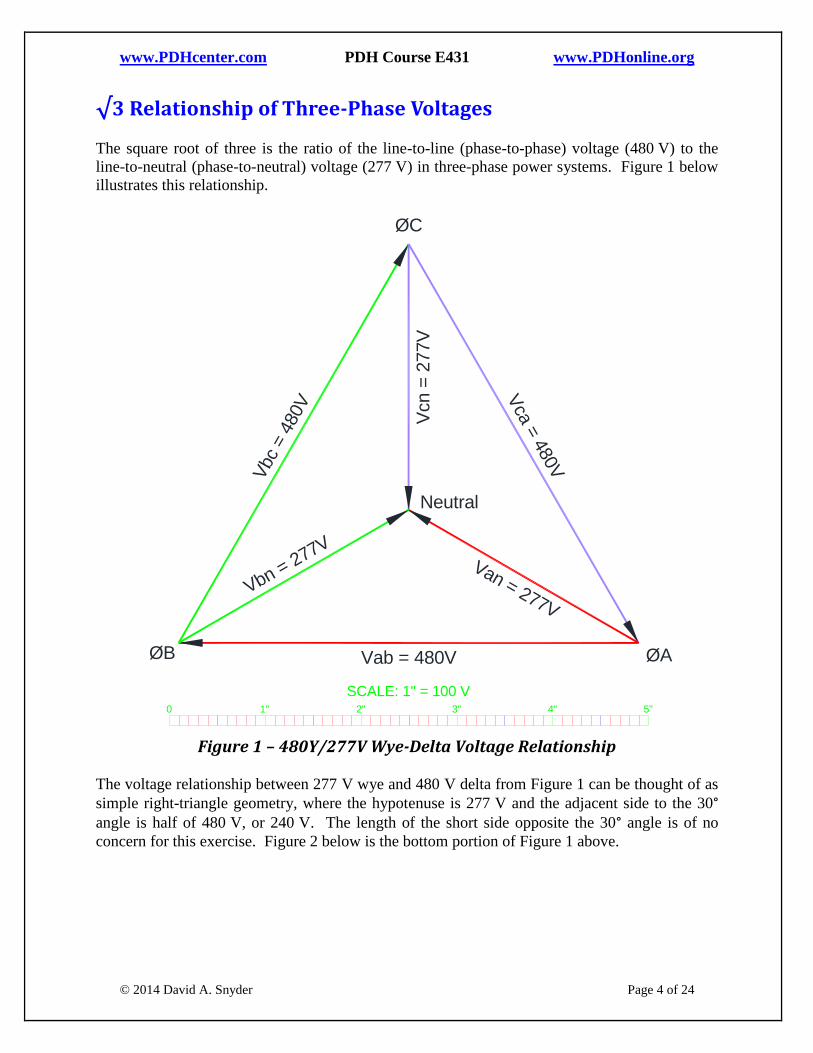
The square root of three is the ratio of the line-to-line (phase-to-phase) voltage (480 V) to the
line-to-neutral (phase-to-neutral) voltage (277 V) in three-phase power systems. Figure 1 below
illustrates this relationship.
Figure 1 – 480Y/277V Wye-Delta Voltage Relationship
The voltage relationship between 277 V wye and 480 V delta from Figure 1 can be thought of as
simple right-triangle geometry, where the hypotenuse is 277 V and the adjacent side to the 30° angle is half of 480 V, or 240 V. The length of the short side opposite the 30° angle is of no
concern for this exercise. Figure 2 below is the bottom portion of Figure 1 above. 1 2 3 4 5 6 70
Wye-Delta Voltage Relationships
Figure xyz06
1" 2" 3" 4" 5"0
Vab = 480V
Vca
= 480V
Vbc
= 4
80V
Van = 277V
Vcn =
277V
Vbn = 277V
ØB ØA
ØC
Neutral
SCALE: 1" = 100 V

www.PDHcenter.com PDH Course E431 www.PDHonline.org
© 2014 David A. Snyder Page 5 of 24
Figure 2 –Wye-Delta Voltage Relationship – Right Triangle Geometry
As shown in Figure 2, the length of the 240 V side of both right triangles is related to the length
of the 277 V sides by the cosine of 30°, which is 0.866. Alternatively, we could have used the
60° corner for reference in Figure 2 and stated that the relationship between 240 V and 277 V
was defined by: sin(60°) = 0.866 = 240 V / 277 V to get the same result. The value of 0.866 is
actually √3 / 2, as one might expect from the voltages shown in Figure 2.
The square root of three also comes into play for the voltage applied to a wye-delta motor. See
PDH Online Course E413 Wye-Delta Motor Starters, listed in the Additional Reading section
beginning on page 24.
The same square root of three (√3) relationship between the line-to-line voltage and line-to-
neutral voltage holds true for 280Y/120V as shown in Figure 3 below
1 2 3 4 5 6 70
Wye-Delta Voltage Relationships - Right Trangles
Figure xyz07
240V
277V277V
240V
60°
30°
cos(30°) = 0.866 = 240V / 277V
ØB ØA
1" 2" 3" 4" 5"0
Neutral
SCALE: 1" = 100 V

www.PDHcenter.com PDH Course E431 www.PDHonline.org
© 2014 David A. Snyder Page 6 of 24
Figure 3 – 208Y/120V Wye-Delta Voltage Relationship
The square root of three (√3) relationship holds true for all three-phase power systems, including
400Y/230V and 600Y/347V. See PDH Online Course E427 Standard AC System Voltages
(600 V and Less), listed in the Additional Reading section beginning on page 24, for more
information on various AC system voltages.
Having discussed the use of the square root of three in the relationship of three-phase voltages,
let’s move on to our next topic, the use of the square root of three in three-phase line current
calculations.
√3 In Three-Phase Line Current Calculations
The line current is the current in the power conductors going to the load. The line current,
therefore, is the current used in sizing the conductors for a circuit, as well as for sizing the
protective device, such as a breaker or fuse. In this section, and associated sub-sections, we will
see that the square root of three can be used to determine the line current for balanced, three-
phase loads, but not unbalanced, three-phase loads. As previous stated, it is assumed that the line
conductors from the power source to the loads have no resistance and no reactance.
1 2 3 4 5 6 70
208Y/120V Voltage Relationships
Figure xyz08
1" 2" 3" 4" 5"0
208V
208V
208V
120V
120V
120V
ØB ØA
ØC
Neu.
SCALE: 1" = 100 V

www.PDHcenter.com PDH Course E431 www.PDHonline.org
© 2014 David A. Snyder Page 7 of 24
In this section, we will look at delta-connected and wye-connected resistance three-phase loads.
The following table can serve as a quick guide in finding the appropriate section:
Type of Load for Three-Phase Line Current Examples Page #
Balanced, Delta-Connected, Three-Phase, Resistance Loads 7
Unbalanced, Delta-Connected, Three-Phase, Resistance Loads 10
Balanced, Wye-Connected, Three-Phase, Resistance Loads without Neutral
Connection
13
Unbalanced, Wye-Connected, Three-Phase, Resistance Loads with Neutral
Connection
16
Table 1 – Types of Loads for Line Current Examples
Impedance loads are not discussed in this course, but the concepts are basically the same as for
resistance loads. The main difference for impedance loads is that the current vectors will lag
behind the voltage vectors by the power factor angle, for lagging power factors, of course.
Delta-Connected, Three-Phase, Resistance Loads
Let’s start by looking at balanced, delta-connected, three-phase, resistive loads, then we will
move on to unbalanced, delta-connected, three-phase, resistive loads in a later section.
Balanced, Delta-Connected, Three-Phase, Resistance Loads
Figure 4 shows a balanced, three-phase resistance load connected in delta and powered by a
480 V, 3-phase, 3-wire delta source. This is known as a balanced, three-phase load because all
three of the loads are equal to each other: 10 KW, in this example. Since there are three 10 KW
loads, the total load is 30 KW in Figure 4. When calculating the current flow to a balanced
30 KW load at 480 V, three-phase, we simply divide the total load by the applied line-to-line
voltage and the square root of three, thusly: 30,000 W / (480V * √3) = 36.1 A. This is the value
of each of the line currents Ia, Ib, and Ic, but they are 120° apart from each other.
Figure 4 – 30 KW, Balanced, Delta-Connected, Three-Phase, Resistance Load 30KW, Balanced, Delta-Connected Resistance
Figure xyz01
1 2 3 4 5 6 70
ØAØB480V
480V
480V
ØC
ØAØBVab = 480V
Vca
= 4
80V
Vbc
= 4
80V
ØC
Ib
Ia
Ic
Ia = Iab - IcaIb = Ibc - IabIc = Ica - Ibc
Iab
Ibc
Ica
10K
W
10KW
10K
W

www.PDHcenter.com PDH Course E431 www.PDHonline.org
© 2014 David A. Snyder Page 8 of 24
Where does the √3 value come from – why do we include it in this calculation? It is a direct
result of the geometry of an equilateral triangle, in which all three sides are equal, and the fact
that the line current (Ia) going to each connection of the load is equal to the vector sum of the
currents (such as Iab + -Ica) at that connection. To visualize this, look at Figure 4, in which the
current Ia coming from phase A of the power source is equal to the sum of the +Iab and –Ica.
This does not imply a simple addition of the magnitudes of the currents in each leg to get the
total, but, instead, it is the vector sum of +Iab and –Ica, as illustrated in Figure 7 on page 9. Let’s
choose one of the three legs at random, the one between phase A and Phase B. The current in
that leg and in each leg of the balanced load is 10,000 W / 480V = 20.83 A. The angle or
direction of that current is in the same angle or direction as the applied voltage, since the load is
composed of resistance only, for this example. Figure 5 below shows the angle of Vab and Iab
for the 10 KW load connected between phase A and phase B of the power source.
Figure 5 – Voltage Vab and Current Iab in Delta-Connected, Resistance Load
Since voltage Vab in Figure 5 is applied to a resistance, not an inductance, the current vector is
in the same direction as the applied voltage. As mentioned previously, if the load were
composed of impedances instead of pure resistances, the current and voltage vectors in each
phase would be separated from each other by the impedances’ power factor angle.
Notice that we didn’t use the square root of three to calculate the current in one phase-to-phase
load inside the delta-connected load. The current value of 20.83 A is the same for each of three
legs, but the direction of each current is different in each case, since the vector direction of the
applied voltage is different in each case. See Figure 6 below for vector representations of the
three applied voltages and three resulting currents for the balanced 30 KW load we are presently
discussing.
Figure 6 – Relationships between Three-Phase Voltages and Currents for Resistance Load
Figure xyz11
1 2 3 4 5 6 7
Direction of Iab is Dependent on Vab
Figure xyz11
0
Vab
Iab
1 2 3 4 5 6 7
Currents and Voltage in a 200 Hp, Wye-Connected Motor
Figure xyz12
0
Vab
Iab
Vbc
Ibc Ica
Vca
www.PDHcenter.com PDH Course E431 www.PDHonline.org
© 2014 David A. Snyder Page 9 of 24
The magnitudes of the currents and voltages are not shown in Figure 5 and Figure 6, just the
directions of the vectors.
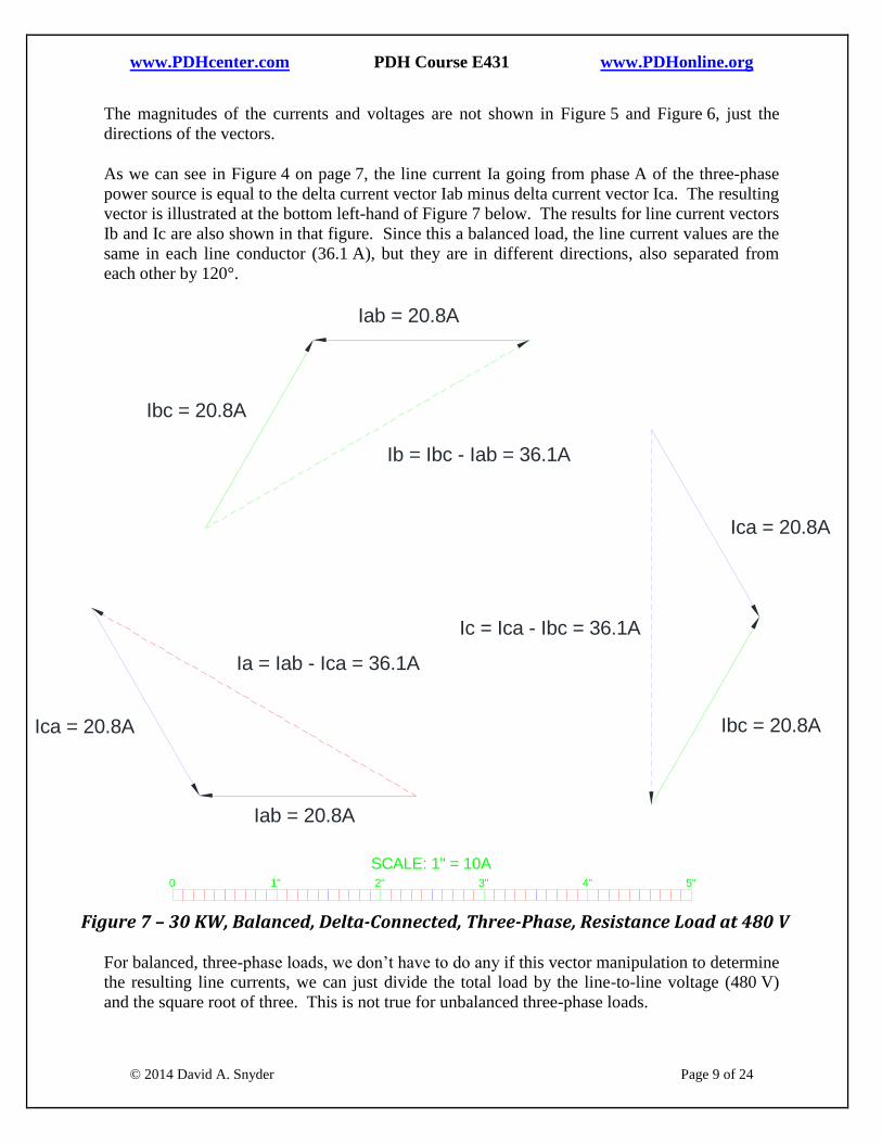
As we can see in Figure 4 on page 7, the line current Ia going from phase A of the three-phase
power source is equal to the delta current vector Iab minus delta current vector Ica. The resulting
vector is illustrated at the bottom left-hand of Figure 7 below. The results for line current vectors
Ib and Ic are also shown in that figure. Since this a balanced load, the line current values are the
same in each line conductor (36.1 A), but they are in different directions, also separated from
each other by 120°.
Figure 7 – 30 KW, Balanced, Delta-Connected, Three-Phase, Resistance Load at 480 V
For balanced, three-phase loads, we don’t have to do any if this vector manipulation to determine
the resulting line currents, we can just divide the total load by the line-to-line voltage (480 V)
and the square root of three. This is not true for unbalanced three-phase loads.
30 KW Balanced,Delta-Connected Load
Figure xyz03
1 2 3 4 5 6 70
1" 2" 3" 4" 5"0
SCALE: 1" = 10A
Ia = Iab - Ica = 36.1A
Iab = 20.8A
Ica = 20.8A
Ib = Ibc - Iab = 36.1A
Ibc = 20.8A
Iab = 20.8A
Ic = Ica - Ibc = 36.1A
Ica = 20.8A
Ibc = 20.8A
www.PDHcenter.com PDH Course E431 www.PDHonline.org
© 2014 David A. Snyder Page 10 of 24
Unbalanced, Delta-Connected, Three-Phase, Resistance Loads
Unbalanced three-phase loads are largely ignored in technical publications and design guides,
but such installations are not uncommon, such as eight 1,000 W lighting fixtures on a high-mast
lighting pole powered by 480 V, three-phase. It is not accurate to divide 8,000 W by 480 V
and √3 to come up with a line current of 9.6 A, but it is a close-enough approximation to select
the proper breaker and conductor size for this circuit. Let’s consider a similar example with a
purely resistive, unbalanced, delta-connected three-phase load.
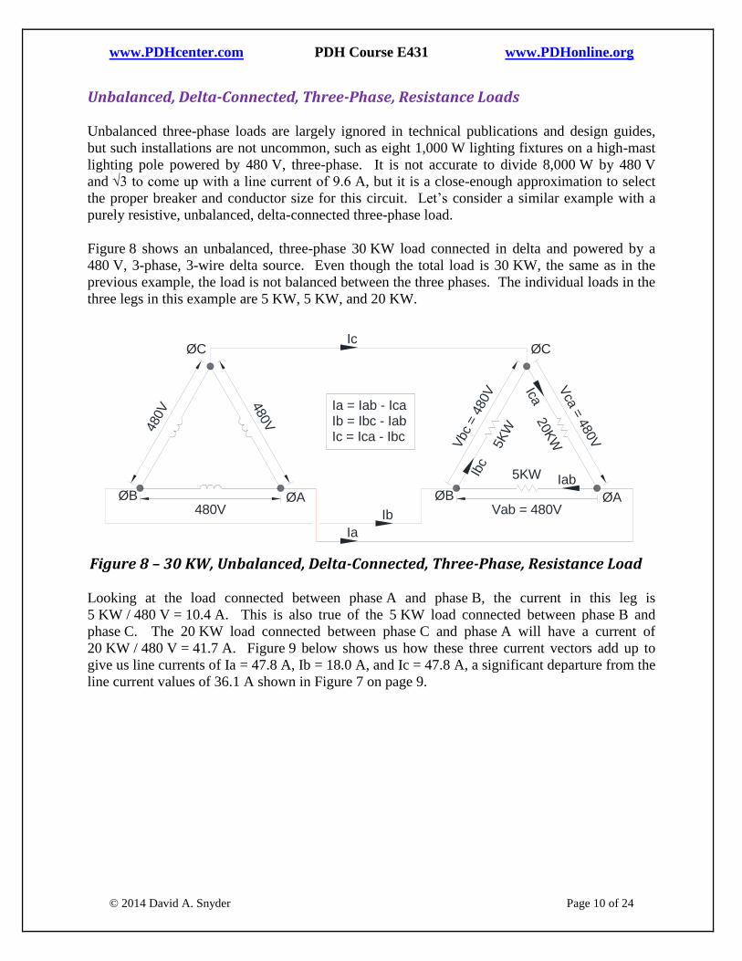
Figure 8 shows an unbalanced, three-phase 30 KW load connected in delta and powered by a
480 V, 3-phase, 3-wire delta source. Even though the total load is 30 KW, the same as in the
previous example, the load is not balanced between the three phases. The individual loads in the
three legs in this example are 5 KW, 5 KW, and 20 KW.
Figure 8 – 30 KW, Unbalanced, Delta-Connected, Three-Phase, Resistance Load
Looking at the load connected between phase A and phase B, the current in this leg is
5 KW / 480 V = 10.4 A. This is also true of the 5 KW load connected between phase B and
phase C. The 20 KW load connected between phase C and phase A will have a current of
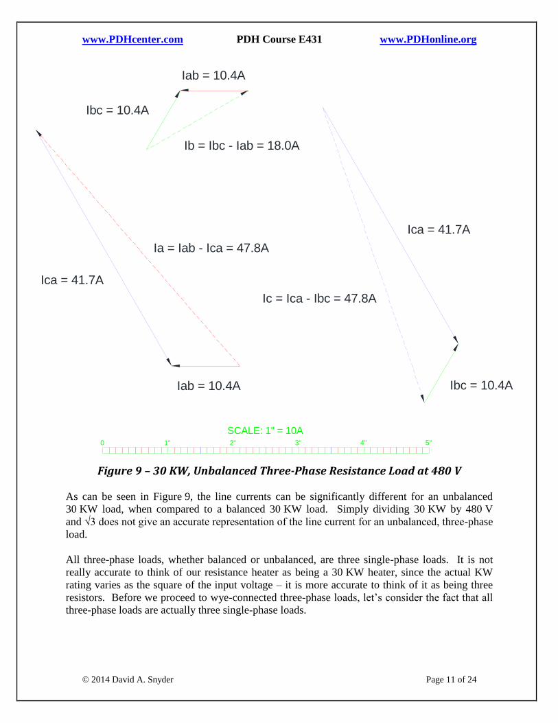
20 KW / 480 V = 41.7 A. Figure 9 below shows us how these three current vectors add up to
give us line currents of Ia = 47.8 A, Ib = 18.0 A, and Ic = 47.8 A, a significant departure from the
line current values of 36.1 A shown in Figure 7 on page 9.
1 2 3 4 5 6 70
30KW, Unbalanced, Delta-Connected Resistance
Figure xyz02
ØAØB480V
480V
480V
ØC
ØAØBVab = 480V
Vca
= 4
80V
Vbc
= 4
80V
ØC
Ib
Ia
Ic
Ia = Iab - IcaIb = Ibc - IabIc = Ica - Ibc
IabIb
c
Ica
5K
W
5KW
20K
W
www.PDHcenter.com PDH Course E431 www.PDHonline.org
© 2014 David A. Snyder Page 11 of 24
Figure 9 – 30 KW, Unbalanced Three-Phase Resistance Load at 480 V
As can be seen in Figure 9, the line currents can be significantly different for an unbalanced
30 KW load, when compared to a balanced 30 KW load. Simply dividing 30 KW by 480 V
and √3 does not give an accurate representation of the line current for an unbalanced, three-phase
load.
All three-phase loads, whether balanced or unbalanced, are three single-phase loads. It is not
really accurate to think of our resistance heater as being a 30 KW heater, since the actual KW
rating varies as the square of the input voltage – it is more accurate to think of it as being three
resistors. Before we proceed to wye-connected three-phase loads, let’s consider the fact that all
three-phase loads are actually three single-phase loads.
30 KW Unbalanced Load
Figure xyz04
1 2 3 4 5 6 70
1" 2" 3" 4" 5"0
Ia = Iab - Ica = 47.8A
Iab = 10.4A
Ica = 41.7A
Ibc = 10.4A
Iab = 10.4A
Ib = Ibc - Iab = 18.0A
Ica = 41.7A
Ibc = 10.4A
Ic = Ica - Ibc = 47.8A
SCALE: 1" = 10A
www.PDHcenter.com PDH Course E431 www.PDHonline.org
© 2014 David A. Snyder Page 12 of 24
Balanced Three-Phase Load as Three Single-Phase Loads
If a typical, balanced resistance heater is rated 30 KW at 480 V, three-phase, then it would be
rated at a much lower KW value at 208 V, three-phase; a value that would be proportional to the
squares of the two voltages in question:
Ratio = (208)2 : (480)
2 = 43,264 : 230,400 = 0.188 : 1
Applying this ratio to the 30 KW heater at 480 V, three-phase gives us a new KW value at
208 V, three-phase:
New KW = 30 KW * 0.188 = 5.63 KW
This concept might be easier to see if we convert the so-called 30 KW heater into its three
resistance values. Each of the three legs of the heater is rated 10 KW when 480 V is applied
across the leg in question, as shown in Figure 4 on page 7. Ohm’s law tells us that:
P = V * I = V * (V / R) = V2 / R
We know the power P is 10 KW for one leg and the voltage V is 480 V across the leg, so:
10,000 = (480)2 / R
Rearranging the above equation:
R = (480)2 / 10,000 = 23 Ω
What would be the current through 23 Ω with 480 V applied? It would be 480 / 23 = 20.8 A,
which is the same value for each of the leg currents in Figure 7 on page 9.
What would be the current through 23 Ω with the lower voltage of 208 V applied? It would be
208 / 23 = 9 A, which is simply a linear relationship to 20.8 A at 480 V, but when multiplying
the currents by the associated voltages, there is a significant difference in the KW ratings of the
heater at the two different voltages. We already know that each leg is a 10 KW load at 480 V,
but the same resistance will have a much lower KW value at 208 V:
P = V * I = 208 V * 9 A = 1,872 W
The total for three resistances:
P = 3 * 1,872 W = 5,616 W, which we have already calculated near the beginning of this
section to be 5.63 KW. If a calculator is used instead of relying on the rounded-off
values in this example, the results will match up more precisely.
www.PDHcenter.com PDH Course E431 www.PDHonline.org
© 2014 David A. Snyder Page 13 of 24
Unbalanced Three-Phase Load as Three Single-Phase Loads
Looking back at the unbalanced 30 KW load in Figure 8 on page 10, composed of one 20 KW
leg and two 5 KW legs, the one 20 KW load at 480 V is actually a resistance of:
R = (480)2 / 20,000 = 11.5 Ω (half the 10 KW resistance)
The current in the 20 KW leg is 480 V / 11.5 Ω = 41.7 A (twice the 10 KW current), as
previously shown in Figure 9 on page 11.
Each of the two 5 KW legs has a resistance value of:
R = (480)2 / 5,000 = 46 Ω (twice the 10 KW resistance)
The current in each of the 5 KW legs is 480 / 46 = 10.4 A, as previously shown in Figure 9 on
page 11.
Let’s get back to our discussion of three-phase resistance loads. We have already discussed
balanced and unbalanced delta-connected, three-phase, resistance loads, but let’s now turn our
attention to wye-connected loads.
Wye-Connected, Three-Phase, Resistance Loads
Let’s start by looking at balanced, wye-connected, three-phase, resistive loads, then we will
move on to unbalanced, wye-connected, three-phase, resistive loads in a later section.
Balanced, Wye-Connected, Three-Phase, Resistance Loads without Neutral Connection
Figure 10 below shows a balanced, three-phase load connected in wye and powered by a 480 V,
3-phase, 3-wire delta source, without a neutral connection. We simply rearranged the three
resistance heaters from Figure 4 on page 7 into a wye configuration. They were each 10 KW in
Figure 4, but that is not true when they are arranged as shown in Figure 10. As discussed earlier,
this is known as a balanced, three-phase load because all three of the loads are equal to each
other: 23 Ω, in this example. Since the loads are connected in wye with 480V applied to the
outside connections, there is only 277 V across each resistance. This was illustrated in Figure 1
on page 4.
When 277 V is applied across 23 Ω, the current will be 277 V / 23 Ω = 12 A. The power across
each resistance will be 277 V * 12 A = 3,324 W. Since there are three 3,324 W loads, the total
load is 9,972 W, which is nominally 10 KW worth of load in Figure 10 below. When calculating
the current flow to a balanced 10 KW load at an applied voltage of 480 V, three-phase, we
simply divide the total load by the applied line-to-line voltage and the square root of three,
thusly: 10,000 W / (480V * √3) = 12 A. Notice that the line current, such as Ia, is equal to the
phase current inside the wye, namely Ian. Notice, also, that the line current for the same load

www.PDHcenter.com PDH Course E431 www.PDHonline.org
© 2014 David A. Snyder Page 14 of 24
(23 Ω per phase) connected in wye is one-third (1/3) of that same load when connected in delta.
This is because:
1. The voltage across each of the three resistances is only 480 V / √3 = 277 V when
connected in wye;
2. The resulting current through each of the three resistances at this voltage is the
(480 V current) / √3 = 20.8 A / √3 = 12 A; and
3. The phase current is the same as the line current, which is 12 A in this example, rather
than 36 A (nominally) in Figure 7 on page 9.
As can be seen, the square root of three comes into play twice in the first two line items above to
make a combined ratio of 1/√3 * 1/√3 = 1/3. Another aspect of this wye-delta relationship is that
the input resistance of a wye-connected balanced load is three times the input resistance of a
delta-connected balanced load, as illustrated in Figure 24 in PDH Online Course E413 Wye-
Delta Motor Starters, listed in the Additional Reading section beginning on page 24.
The information just discussed reinforces the ratio of power to the square of the applied voltage –
namely, the ratio = (277)2 : (480)
2 = 76,729 : 230,400 = 0.333 : 1 = 1 : 3 = 10 KW : 30 KW.
Figure 10 – 10 KW, Balanced, Wye-Connected, Three-Phase, Resistance Load, without Neutral
Connection
Figure 10 does not show a neutral connection, and, for a balanced, wye-connected, three-phase
load, there would not be any neutral current. See Figure 12 below for the phase and neutral
currents. Let’s add a neutral conductor, nonetheless, in the next section.
30KW, Balanced, Wye-Connected Resistance without Neutral Connection
Figure xyz05
1 2 3 4 5 6 70
ØAØB480V
480V
480V
ØC
Ib
Ia
Ic
Ia = IanIb = IbnIc = Icn
ØAØB
Van = 277V
Vcn =
277V
Vbn = 277V
ØC
Ian
Ibn
Icn
23ohm
23ohm
23ohm

www.PDHcenter.com PDH Course E431 www.PDHonline.org
© 2014 David A. Snyder Page 15 of 24
Balanced, Wye-Connected, Three-Phase, Resistance Loads with Neutral Connection
As seen in Figure 11 below, the neutral current (In) is equal to the vector sum of the phase-
currents, which is the same as the sum of the line currents (Ia + Ib + Ic). Since, in a balanced,
three-phase circuit, all three of the line currents are of equal amplitude and 120° apart, they add
up to zero, as illustrated in Figure 12.
Figure 11 – 10 KW, Balanced, Wye-Connected, Three-Phase, Resistance Load, with Neutral
Connection
It can be seen from the right-hand side of Figure 12 below that the neutral current (In) is equal to
zero because it is the vector sum of the line currents (Ia + Ib + Ic), which add up vectorially to
zero. In other words, starting at the beginning of vector Ian and working to the arrowhead of that
vector, then adding vector Ibn, then adding vector Icn, brings us back to our starting point at the
beginning of vector Ian, resulting in a total neutral current of zero.
1 2 3 4 5 6 70
10KW, Balanced, Wye-Connected Resistance with Neutral Connection
Figure xyz09
Ib
Ia
Ic
Ia = IanIb = IbnIc = IcnIn = Ia + Ib + Ic
ØAØB
Van = 277V
Vcn =
277V
ØC
Ian
Ibn
Icn
23ohm
23ohm
23ohm
ØAØB
Vbn = 277V
ØC
Vab = 480V
In

www.PDHcenter.com PDH Course E431 www.PDHonline.org
© 2014 David A. Snyder Page 16 of 24
Figure 12 – 10 KW, Balanced, Wye-Connected, Three-Phase Load at 480 V
Let’s consider the unbalanced loads shown previously in Figure 8 on page 10, but connected in
wye instead of in delta.
Unbalanced, Wye-Connected, Three-Phase, Resistance Loads with Neutral Connection
We will include a neutral connection to carry the unbalanced current, as shown in Figure 13
below. Since the neutral conductor is present, it will keep the center of the wye-connected load
at the same potential as the center of the wye-connected power source, assuming zero resistance
in the neutral conductor. This means the center of the wye-connected load will have a potential
difference of 277 V with regard to the three different phase connections, regardless of the
unbalanced load resistance values. The center of the wye-connected power source is almost
always grounded in most installations, but we are ignoring that in Figure 13.
1 2 3 4 5 6 70
10 KW, Balanced, Wye-Connected Load
Figure xyz14
1" 2" 3" 4" 5"0
SCALE: 1" = 10A
Ian = 12A
Ibn = 12AIc
n =
12A
Ian = 12A
Ibn = 12A
Icn =
12A
Ia = IanIb = IbnIc = IcnIn = Ia + Ib + Ic

www.PDHcenter.com PDH Course E431 www.PDHonline.org
© 2014 David A. Snyder Page 17 of 24
Figure 13 – 10 KW, Unbalanced, Wye-Connected, Three-Phase, Resistance Load, with Neutral
Connection
The 11.5 Ω resistance from phase C to neutral will have 277 V applied to it, resulting in a phase
current and line current equal to 277 V / 11.5 Ω = 24.1 A. Both of the 46 Ω resistances, with
277 V across them, will have a current of 277 V / 46 Ω = 6 A flowing through them, in a vector
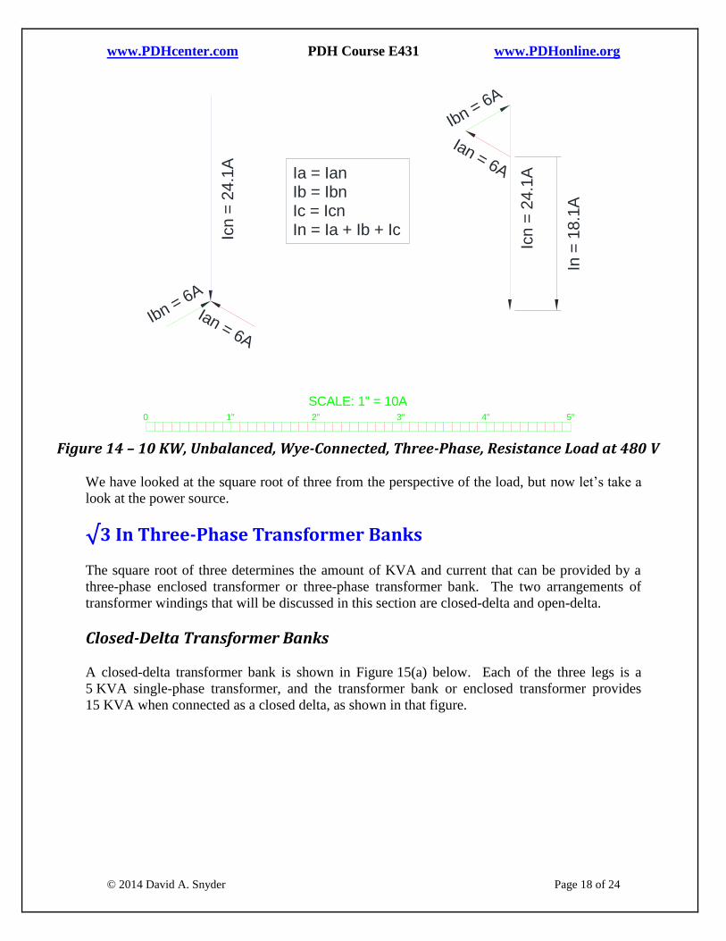
direction determined by the applied voltage, as shown in Figure 14 below.
The neutral current (In) is equal to the vector sum of the phase-currents, which is the same as the
sum of the line currents (Ia + Ib + Ic). Since this is an unbalanced, three-phase load, the
unbalanced current will flow through the neutral conductor back to the source. If the Reader
desires an equation for the neutral current, it is:
N = √(A2 + B
2 + C
2 – AB – BC – CA)
Where: N = the magnitude of neutral current In;
A = the magnitude of line current Ian;
B = the magnitude of line current Ibn;
C = the magnitude of line current Icn.
Plugging in the line current values that we just calculated into the formula above will yield the
same result for the neutral current In as illustrated in Figure 14 below. It is clear from the
formula that the neutral current would be zero if A = B = C.
1 2 3 4 5 6 70
10KW, Unbalanced, Wye-Connected Resistance with Neutral Connection
Figure xyz10
Ib
Ia
Ic
Ia = IanIb = IbnIc = IcnIn = Ia + Ib + Ic
ØAØB
Van = 277V
Vcn =
277V
ØC
Ian
Ibn
Icn
46ohm
46ohm
11.5
ohm
ØAØB
Vbn = 277V
ØC
Vab = 480V
In
www.PDHcenter.com PDH Course E431 www.PDHonline.org
© 2014 David A. Snyder Page 18 of 24
Figure 14 – 10 KW, Unbalanced, Wye-Connected, Three-Phase, Resistance Load at 480 V
We have looked at the square root of three from the perspective of the load, but now let’s take a
look at the power source.
√3 In Three-Phase Transformer Banks
The square root of three determines the amount of KVA and current that can be provided by a
three-phase enclosed transformer or three-phase transformer bank. The two arrangements of
transformer windings that will be discussed in this section are closed-delta and open-delta.
Closed-Delta Transformer Banks
A closed-delta transformer bank is shown in Figure 15(a) below. Each of the three legs is a
5 KVA single-phase transformer, and the transformer bank or enclosed transformer provides
15 KVA when connected as a closed delta, as shown in that figure.
1 2 3 4 5 6 70
10 KW, Unbalanced, Wye-Connected Load with Neutral
Figure xyz15
1" 2" 3" 4" 5"0
SCALE: 1" = 10A
Ian = 6A
Ibn = 6A
Icn =
24.1
A
Ia = IanIb = IbnIc = IcnIn = Ia + Ib + Ic
Ian = 6A
Ibn = 6A
Icn =
24.1
A
In =
18.1
A

www.PDHcenter.com PDH Course E431 www.PDHonline.org
© 2014 David A. Snyder Page 19 of 24
Figure 15 – Three-Phase Delta-Connected Transformer Banks at 240 V
As was seen earlier for a balanced, delta-connected, three-phase resistance load in Figure 4 on
page 7 and Figure 7 on page 9, the line currents are equal to √3 times the phase currents inside of
the delta. The same is true for a closed-delta three-phase transformer bank when the KVA
ratings of all three transformers are the same. The amount of current that each of the 5 KVA
single-phase transformers can provide is 5,000 VA / 240 V = 20.83 A. That is the maximum
current through each transformer inside of the delta. When these delta currents are combined
into line currents on the way to the load, the maximum line current that the closed-delta
transformer bank can provide is √3 times the winding current or 20.83 A * √3 = 36.08 A. This is
shown for the line current Ia in Figure 16(a) below, which is reminiscent of Figure 7 on page 9.
1 2 3 4 5 6 7
Closed-Delta versus Open-Delta Transformer Bank
Figure xyz23 / 15
ØAØB240V
240V
240V
ØC
Ib
Ia
Ic
Ia = Iab - IcaIb = Ibc - IabIc = Ica - Ibc
Iab
Ibc
Ica5K
VA
5K
VA
5KVA
(a) Closed-Delta
ØAØB240V
240V
240V
ØC
Ib
Ia
Ic
Ia = IabIb = Ibc - IabIc = -Ibc
Iab
Ibc
5K
VA
5KVA
(b) Open-Delta

www.PDHcenter.com PDH Course E431 www.PDHonline.org
© 2014 David A. Snyder Page 20 of 24
Figure 16 – Currents in Three-Phase Delta-Connected Transformer Banks at 240 V
Now that we have determined the amount of KVA and line current available from a closed-delta
three-phase transformer, let’s see what happens when one of the transformers is removed, thus
creating an open-delta transformer bank. 1 2 3 4 5 6 7
Currents for Closed-Delta versus Open-Delta Transformer Bank
Figure xyz24
1" 2" 3" 4" 5"0
SCALE: 1" = 10A
Ibc
= 2
0.8
3A
Ica =
20.8
3A
Ia = Iab - IcaIb = Ibc - IabIc = Ica - Ibc
Ica =
20.8
3A
Ia = Iab - Ica = 36.08A
(a) Closed-Delta
(b) Open-Delta
Ia = IabIb = Ibc - IabIc = -Ibc
Iab = Ia = 20.83A
Ibc
= -Ic
= 2
0.8
3A
Ibc
= 2
0.8
3A
Iab = 20.83A
Ib = Ibc - I
ab = 36.08A
Iab = 20.83A Iab = 20.83A

www.PDHcenter.com PDH Course E431 www.PDHonline.org
© 2014 David A. Snyder Page 21 of 24
Open-Delta Transformer Banks
Figure 15(b) on page 19 shows the open-delta three-phase transformer bank that results when
one of the transformers from the closed-delta three-phase transformer bank is removed. As can
be seen in that figure, the maximum line currents Ia and Ic are equal to the winding currents
inside the transformer, or 20.83 A, as shown in Figure 16(b). From that figure, the maximum
line current Ib might seem like it has more available than Ia and Ic, but Ib is the current returning
from the loads connected to Phase A and Phase C. In other words, the most current you can
provide to any load, whether connected A-B, B-C, or C-A, is 20.83 A. This can be visualized
mentally or drawn by hand on Figure 15(b) on page 19. If a load is connected between Phase A
and Phase B, the maximum current that can be provided by the winding between those phases is
20.83 A. Likewise, if a load is connected between Phase B and Phase C, the maximum current
that can be provided by the winding between those phases is 20.83 A. Finally, if a load is
connected between Phase C and Phase A, the current passes through both of the windings, and
that current is still limited to 20.83 A. As we have seen above, this current is related to the line
current of a closed-delta three-phase transformer bank by 1 / √3. The Reader might see technical
documents that say the KVA rating of an open-delta transformer is equal to 58% of the rating of
a closed-delta transformer bank, a ratio that is equal to 1 / √3, the same ratio that was stated for
the line currents in the previous sentence. In other words, the 15 KVA rating of the closed-delta
three-phase transformer bank in Figure 15(a) would have an open-delta rating of
15 KVA / √3 = 8.66 KVA in Figure 15(b).
The Reader might sometimes see the ratio of KVA ratings for open-delta transformer banks to be
87% of the rating of the two transformers, but this works out to be the same as 58% of the rating
of the three transformers. That is, 10 KVA * 87% = 8.66 KVA. The ubiquitous square root of
three still appears in this 87% ratio for open-delta transformer KVA ratings, since 87% is the
result of √3 / 2.
To phrase it yet another way, the KVA rating of the open-delta transformer bank is equal to
√3 times the KVA rating of one transformer, or √3 * 5 KVA = 8.66 KVA.
Thus far, we have considered transformer banks
in which all of the individual transformers are
identical. Sometimes, one of the transformers
in an open-delta transformer bank is center-
tapped to provide 240/120V single-phase power
to receptacles and other single-phase loads.
This transformer is often larger than the other transformer in order to accommodate its single-
phase and three-phase dual functions. Consider Figure 15(b) on page 19 and imagine that the
larger of the two transformers is installed between Phase A and Phase B. This would provide
additional current for loads connected between Phase A and Phase B, but would not provide
additional current to loads connected between Phase B and Phase C or between Phase C and
Phase A.
What is a transformer bank?
A transformer bank is comprised of two or
more single-phase transformers wired together,
typically to provide three-phase power.
www.PDHcenter.com PDH Course E431 www.PDHonline.org
© 2014 David A. Snyder Page 22 of 24
Interested Readers can see PDH Online Course E427 Standard AC System Voltages (600V and
Less), listed in the Additional Reading section beginning on page 24 for further discussion of
transformer arrangements, connections, and voltages.
√3 In Three-Phase Voltage-Drop Calculations
The square-root of three (√3) is used in voltage-drop calculations for balanced three-phase
circuits, such as in this common voltage drop formula:
Vdrop = √3 * R * I * L
where: R = conductor ohms-to-neutral per 1,000 ft
I = line current
L = one-way conductor length for one conductor
Why is the square root of three included in this calculation? It is because the line-to-line (phase-
to-phase) resistance is related to the line-to-neutral (phase-to-neutral) resistance by the square
root of three, the same relationship that was illustrated in Figure 1 on page 4. This is most easily
demonstrated by confirming the measurements shown in Figure 17 below. The line-to-neutral
supply voltage is 3 V, so the line-to-line supply voltage is √3 times that, or 5.196 V, as can be
directly measured in that figure with reasonable accuracy.
www.PDHcenter.com PDH Course E431 www.PDHonline.org
© 2014 David A. Snyder Page 23 of 24
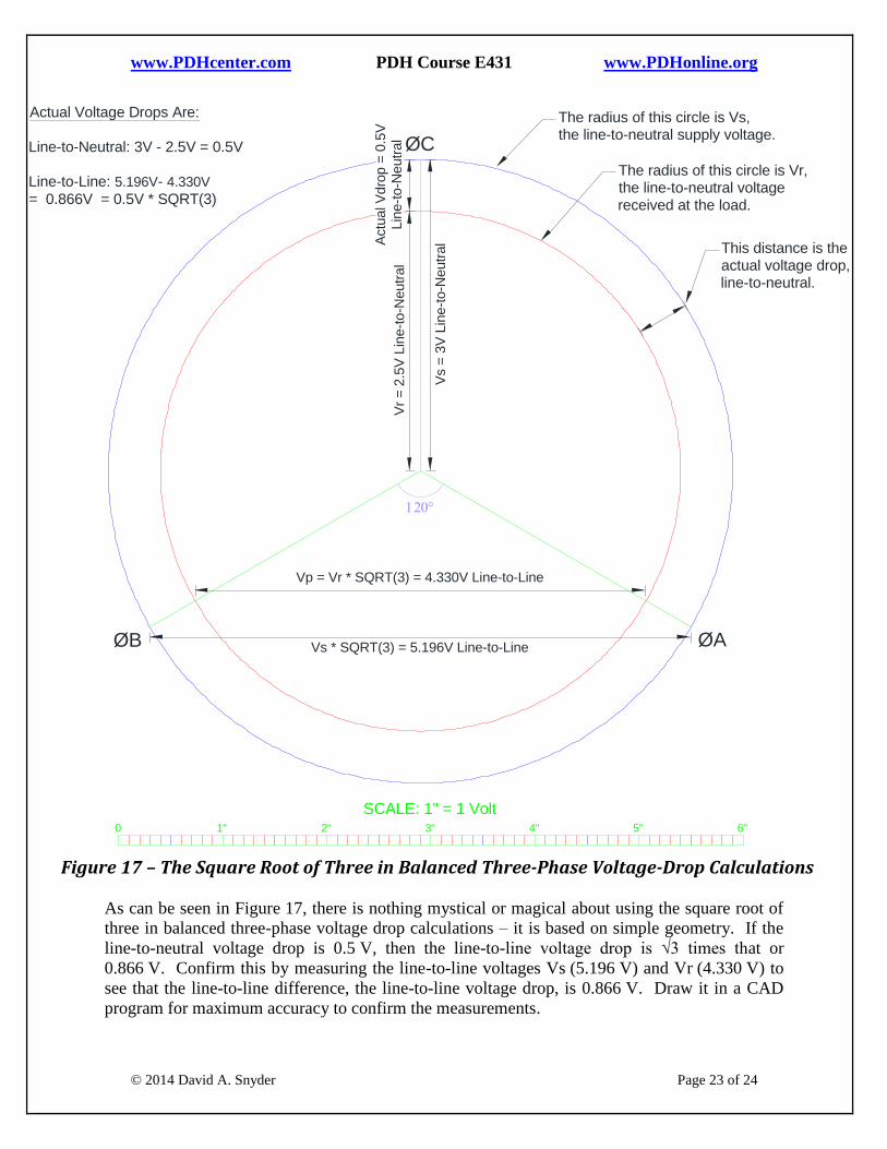
Figure 17 – The Square Root of Three in Balanced Three-Phase Voltage-Drop Calculations
As can be seen in Figure 17, there is nothing mystical or magical about using the square root of
three in balanced three-phase voltage drop calculations – it is based on simple geometry. If the
line-to-neutral voltage drop is 0.5 V, then the line-to-line voltage drop is √3 times that or
0.866 V. Confirm this by measuring the line-to-line voltages Vs (5.196 V) and Vr (4.330 V) to
see that the line-to-line difference, the line-to-line voltage drop, is 0.866 V. Draw it in a CAD
program for maximum accuracy to confirm the measurements.
1 2 3 4 5 6 7
Why the Square Root of Three Is Used for Three-Phase Voltage Drop Calculations
Figure xyz33 / 10
1" 2" 3" 4" 5"0
SCALE: 1" = 1 Volt
Vs =
3V
Lin
e-t
o-N
eutr
al
Vr
= 2
.5V
Lin
e-t
o-N
eutr
al
Actu
al V
dro
p =
0.5
VLin
e-t
o-N
eutr
al
Vs * SQRT(3) = 5.196V Line-to-Line
Vp = Vr * SQRT(3) = 4.330V Line-to-Line
Actual Voltage Drops Are:
Line-to-Neutral: 3V - 2.5V = 0.5V
Line-to-Line: 5.196V- 4.330V
= 0.866V = 0.5V * SQRT(3)
The radius of this circle is Vs,the line-to-neutral supply voltage.
The radius of this circle is Vr,the line-to-neutral voltagereceived at the load.
This distance is theactual voltage drop,line-to-neutral.
ØAØB
ØC
6"

www.PDHcenter.com PDH Course E431 www.PDHonline.org
© 2014 David A. Snyder Page 24 of 24
The three-phase voltage drop formula at the beginning of this section is used by many people,
and it is a reasonable approximation of voltage drop, but there is a more accurate formula to
obtain the Actual voltage drop. Interested Readers can peruse PDH Online course E426 Voltage
Drop Calculations, listed in the section Additional Reading beginning on page 24.
In Closing
The square root of three is used every day in several types of three-phase electrical calculations,
though not everyone understands the reasons why. The square root of three is applicable to a
variety of balanced three-phase circuits and calculations, but usually not to unbalanced three-
phase circuits and calculations.
Abbreviations
A Amp or Amps
AC Alternating Current
N.A. Not Applicable
V Volt or Volts
VAC Volts Alternating Current
Additional Reading
PDH Online course E336 Calculating Currents in Balanced and Unbalanced Three Phase
Circuits at www.pdhonline.org
PDH Online course E413 Wye-Delta Motor Starters at www.pdhonline.org
PDH Online course E426 Voltage Drop Calculations at www.pdhonline.org
PDH Online course E427 Standard AC System Voltages (600 V and Less) at www.pdhonline.org
· · — · · · · · · · · · · · · — — · — — — — — · · · · · · · — — · — · · — · — · — · ·


![Hardware Security · TPM Capabilities [3] • Provides three root of trusts: • Root of trust for measurement (RTM) a trusted implementation of a hash algorithm • Root of trust](https://static.fdocuments.in/doc/165x107/5e6a903714661d58753a312a/hardware-security-tpm-capabilities-3-a-provides-three-root-of-trusts-a-root.jpg)