THE SPECTRAL ANALYSIS OF AN AERO-ENGINE ASSEMBLY ... · THE SPECTRAL ANALYSIS OF AN AERO-ENGINE...
26
THE SPECTRAL ANALYSIS OF AN AERO-ENGINE ASSEMBLY INCORPORATING A SQUEEZE-FILM DAMPER R. Holmes and M.M. Dede Department of Mechanical Engineering University of Southampton Southampton, England Aero-engine structures have very low inherent damping and so artificial damping is often introduced by pumping oil into annular gaps between the casings and the outer races of some o r all of the rolling-element bearings supporting the rotors. The thin oil films so formed are called squeeze film dampers and they can be beneficial in reducing rotor vibration due to unbalance and keeping to reasonable limits the forces transmitted to the engine casing. However, squeeze-film dampers are notoriously non-linear and as a result can introduce into the assenbly such phenomena as subhamonic oscillations, jumps and combi- nation frequencies. The purpose of the research described in this paper is to investigate such phenomena both theoretically and experimentally on a test facility reproducing the essential features of a medium-size aero engine. The forerunner of this work has been published in refs. [1],[2]. It was concerned with the examination of a squeeze-film damper in series with housing flexibility when supporting a rotor. The structure represented to a limited extent the essentials of the projected Rolls Royce RB401 engine. That research demonstrated the ability to calculate the oil-film forces arising from the squeeze film from known motions of the bearing components and showed that the dynamics of a shaft fitted with a squeeze film bearing can be predicted rea- sonably accurately. An aero-engine will normally have at least two shafts and so in addition to the excitation forces which are synchronous with the rotation of one shaft, there will also be forces at other frequencies from other shafts operating on the squeeze-film damper. The present paper is concerned with theoretical and experimental work to consider severe loading of squeeze-film dampers and to include these additional effects. The theoretical methods are similar to those discussed in references [ll and 121. Now with General Electric Company, Cincinnati, U.S.A. 61 PRECEDING PAGE BLANK NOT FILMED https://ntrs.nasa.gov/search.jsp?R=19890013524 2018-07-13T18:58:50+00:00Z
Transcript of THE SPECTRAL ANALYSIS OF AN AERO-ENGINE ASSEMBLY ... · THE SPECTRAL ANALYSIS OF AN AERO-ENGINE...
THE SPECTRAL ANALYSIS OF AN AERO-ENGINE ASSEMBLY
INCORPORATING A SQUEEZE-FILM DAMPER
R. Holmes and M.M. Dede Department o f Mechanical Engineering
University o f Southampton Southampton, England
Aero-engine s t r u c t u r e s have very low inhe ren t damping and s o a r t i f i c i a l damping is o f t e n introduced by pumping o i l i n t o annular gaps between t h e cas ings and the o u t e r races of some o r a l l of t he rol l ing-element bear ings suppor t ing the r o t o r s .
The t h i n o i l f i l m s s o formed a r e c a l l e d squeeze f i l m dampers and they can be b e n e f i c i a l i n reducing r o t o r v i b r a t i o n due t o unbalance and keeping t o reasonable l i m i t s t h e f o r c e s t r ansmi t t ed t o t h e engine cas ing . However, squeeze-film dampers a r e no to r ious ly non-linear and as a r e s u l t can in t roduce i n t o t h e assenbly such phenomena as subhamonic o s c i l l a t i o n s , jumps and combi- na t ion f requencies .
The purpose of t h e research descr ibed i n t h i s p a p e r is t o i n v e s t i g a t e such phenomena both t h e o r e t i c a l l y and experimental ly on a t e s t f a c i l i t y reproducing t h e e s s e n t i a l f e a t u r e s of a medium-size aero engine.
The forerunner of t h i s work has been publ ished i n r e f s . [ 1 ] , [ 2 ] . I t was concerned wi th the examination of a squeeze-film damper i n s e r i e s wi th housing f l e x i b i l i t y when suppor t ing a r o t o r . The s t r u c t u r e represented t o a l i m i t e d e x t e n t t h e e s s e n t i a l s of t he pro jec ted R o l l s Royce RB401 engine. That research demonstrated the a b i l i t y t o c a l c u l a t e t he o i l - f i lm f o r c e s a r i s i n g from t h e squeeze f i l m from known motions of the bear ing components and showed t h a t t he dynamics of a s h a f t f i t t e d w i t h a squeeze f i l m bearing can be p red ic t ed rea- sonably accu ra t e ly .
An aero-engine w i l l normally have a t l e a s t two s h a f t s and s o i n a d d i t i o n t o the e x c i t a t i o n f o r c e s which a r e synchronous w i t h t he r o t a t i o n of one s h a f t , t he re w i l l a l s o be f o r c e s a t o t h e r f requencies from o t h e r s h a f t s ope ra t ing on the squeeze-fi lm damper. The present paper is concerned w i t h t h e o r e t i c a l and experimental work t o cons ider severe loading of squeeze-fi lm dampers and t o inc lude these a d d i t i o n a l e f f e c t s . The t h e o r e t i c a l methods a r e similar t o those d iscussed i n re ferences [ l l and 121.
Now wi th General E l e c t r i c Company, C inc inna t i , U . S . A .
61 PRECEDING PAGE BLANK NOT FILMED
https://ntrs.nasa.gov/search.jsp?R=19890013524 2018-07-13T18:58:50+00:00Z
a
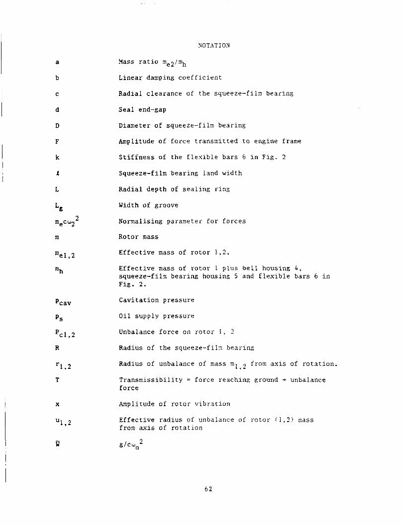
NOTATION
?lass ratio me2imh
b
C
d
D
F
k
L
L
2 mecu2
m
mel , 2
mh
Pcav
PS
PC1.2
R
1 * 2 r
T
X
1 * 2 U
- W
Linear damping coefficient
Radial clearance of the squeeze-fih bearing
Seal end-gap
Diameter of squeeze-film bearing
Amplitude of force transmitted to engine frame
Stiffness of the flexible bars 6 in Fig. 2
Squeeze-film bearing land width
Radial depth of sealing ring
Width of groove
Nomalising paraaeter for forces
Rotor mass
Effective mass of rotor 1.2.
Effective inass of r o t o r 1 p l u s bell housing 4 , squeeze-filn bearing housing 5 and flexible bars 6 in Fig. 2.
Cavitation pressure
Oil supply pressure
Unbalance force on r o t o r 1 , 2
Radius of the squeeze-filx bearing
Radius of unbalance of mass m 1
Transmissibility = force reaching ground - unbalance force
from axis of rotation. .I
Amplitude of rotor vibration
Effective radius of unbalance o f rotor ( 1 , 3 ) xass from axis of rotation
d C y l 2
6 2
or
x
Y
w 1 . 2
Boundary-condition f a c t o r
A t t i t u d e angle
E c c e n t r i c i t y r a t i o
Dynamic v i s c o s i t y
Nomal i s ing pararneter f o r pressures
Angular v e l o c i t y of r o t o r 1 . 2 .
Undamped n a t u r a l frequency
D i f f e r e n t i a t i o n with r e spec t t o w t
THE TEST F A C I L I T Y
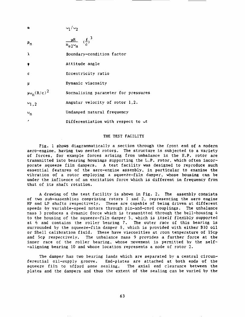
F i g . 1 shows diagrammatically a s e c t i o n through t h e f r o n t end of a modern aero-engine, having two nested r o t o r s . The s t r u c t u r e is subjec ted t o a v a r i e t y of f o r c e s , f o r example f o r c e s a r i s i n g from unbalance i n t h e H.P. r o t o r are t r ansmi t t ed i n t o bear ing housings suppor t ing the L.P. r o t o r . which o f t e n incor- po ra t e squeeze f i l m dampers. A t e s t f a c i l i t y was designed t o reproduce such e s s e n t i a l f e a t u r e s of t he aero-engine assembly, i n p a r t i c u l a r t o examine t h e v i b r a t i o n of a r o t o r employing a squeeze-fi lm damper, whose housing can be under the in f luence of an e x c i t a t i o n fo rce which is d i f f e r e n t i n frequency from tha t of i ts s h a f t r o t a t i o n .
A drawing of t h e t e s t f a c i l i t y i s shown i n F i g . 2 . The asseinbly c o n s i s t s of two sub-assemblies comprising r o t o r s I and 2 , r ep resen t ing the ae ro engine trP and LP s h a f t s r e spec t ive ly . These a r e capable of being d r iven a t d i f f e r e n t speeds by var iable-speed motors through pin-and-cord coupl ings. The unbalance sass 3 produces a dynamic fo rce which is t ransmi t ted through the bell-housing 4 t o t he housing of t h e squeeze- f i ix dasper 5 , which is i t s e l f f l e x i b l y supported a t 6 and con ta ins the r o l l e r bear ing 7 . The o u t e r race of t h i s bear ing is surrounded by the squeeze-film damper 3 , which is provided wi th e i t h e r R10 o i l o r S h e l l c a l i b r a t i o n f l u i d . These have v i s c o s i t i e s a t roorn t eape ra tu re of 15cp and 5cp r e spec t ive ly . The unbalance mass 9 provides a f u r t h e r f o r c e a t t h e i n n e r race of t he r o l l e r bear ing, whose rnovement is p e m i t t e d by the s e l f - - a l ign ing bearing 10 and whose loca t ion r ep resen t s a node of r o t o r 1 .
The damper has two bear ing lands which a r e sepa ra t ed b:; a c e n t r a l circum- f e r e n t i a l oi l -supply groove. End-plates a r e a t t ached a t both ends of t h e squeeze f i l a to a f f o r d some s e a l i n g . The ax ia l end c learance between the p l a t e s and the dampers and thus the e x t e n t of t h e s e a l i n g can be va r i ed by the
63
i n s e r t i o n of spacing s h i a s . The r o t a t i o n of t h e damper journa l is prevented by dogs loca ted i n one of the end p l a t e s , providing s u f f i c i e n t c learance t o a l low the jou rna l t o zove i n any pa r t of the squeeze- f i ln c learance space. The squeeze- f i ln damper d i a n e t e r is s e t by the o u t e r race of the r o l l e r bear ing 7 (140 mm!. The damper land length and i t s r a d i a l c learance a r e t y p i c a l of ae ro engine a p p l i c a t i o n ( F i g . 3 ) .
The r i g parameters
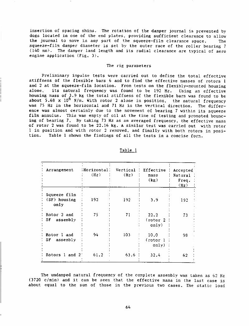
P r e l i a i n a r y i z p u l s e t e s t s were c a r r i e d out t o de f ine the t o t a l e f f e c t i v e s t i f f n e s s of the f l e x i b l e ba r s 5 and t o f i n d the e f f e c t i v e masses of r o t o r s 1 and 2 a t t he squeeze-fi lm loca t ion . From t e s t s on t h e flexibly-mounted housing a lone , i t s na tu ra l frequency was found t o be 192 Hz. Us ing an e f f e c t i v e housing inass of .3 kg the t o t a l s t i f f n e s s of t h e f l e x i b l e bars was found t o be
was 7 5 Hz i n the ho r i zon ta l and 71 Hz i n the v e r t i c a l d i r e c t i o n . The d i f f e r - ence was almost c e r t a i n l y due t o the novenent of bear ing 7 w i th in i ts squeeze f i l m annulus . This was empty of o i l a t the t i n e of t e s t i n g and promoted bounc- ing of bear ing 7 , By taking 73 Hz a s an averaged frequency, t he e f f e c t i v e mass of r o t o r 2 was found t o be 22.16 kg. A similar t e s t was c a r r i e d out wi th r o t o r 1 i n p o s i t i o n and wi th r o t o r 1 rernoved, and f i n a l l y wi th both r o t o r s i n posi- t i o n . Table 1 shows the f ind ings of a l l t h e t e s t s i n a concise fom,.
about 5.68 x 10 2 N / m . With r o t o r 2 a lone i n p o s i t i o n , the na tura l frequency
Table 1
t I I
I Arrangement :Hor i zon ta l : V e r t i c a l I E f f e c t i v e Accepted I (Hz) I ( H z ) mass : Natural :
I I Freq. , I
Squeeze f i l m (SF) housing
only
Rotor 2 and SF assembly
Rotor 1 and SF assembly
Rotors 1 and
, f I I I
I 192 192 I I I I
I
I 75 71 I I
I I
I
I 1 54 103 I
I I I
I I I
21 6 1 . 2 I 43.4 I
3.9
22 .2 ( r o t o r 2
on ly )
10 .o ( r o t o r 1
on ly )
32.4
I I 192 ! , I
I I 73 : I I
, I
1
I 98 , I I
I
, I 62 1 I
I I I
The undamped n a t u r a l frequency of the complete assenbly was taken as 62 Hz (3720 c/min) and i t can be seen t h a t the e f f e c t i v e mass i n the l a s t case is about equal t o the sum of those i n the previous two cases . The s t a t i c l o a d
6 4
provided by r o t o r 2 on the squeeze-fi lm was ha l f its weight, corresponding t o 5 0 / 2 o r 25 kg. The dynamic loads a rose from the unb3alance nasses 3 and 9 , and can be expressed as Pcl = m l r l w 1 2 and Pc2 = m 2 r , w 2 - . where m1 and TI? a r e re- s p e c t i v e l y the unbalance masses on r o t o r s 1 and f, r l , r2 a r e the r a d i i of the mass l o c a t i o n s from t h e c e n t r e of r o t a t i o n of each s h a f t , and w1 and w2 a r e the speeds of t h e s h a f t s . However, i n the a n a l y s i s i t is more convenient t o con- s i d e r t he unbalance mass-radius product t o have a magnitude equal t o the t o t a l e f f e c t i v e mass of each r o t o r a t an e f f e c t i v e unbalance r ad ius u.
SINGLE-SHAFT VERSION OF THE TEST FACILITY
The t e s t f a c i l i t y was f i r s t sepa ra t ed i n t o i t s two r o t o r components by renovirig the b e l l housing 4 . Tes t s were c a r r i e d ou t on the LP r o t o r ( 2 ) a lone mounted i n the squeeze-fi lm damper t o i n v e s t i g a t e i t s perforxance c h a r a c t e r i s - t i c s .
A diagrammatic r ep resen ta t ion of the t e s t f a c i l i t y i n t h i s conf igu ra t ion is g iven i n F i g . 4 . The degree of danping o f f e r e d by the squeeze-film is q u i t e c r i t i c a l . I f i t is too g r e a t t he damper ope ra t e s r a t h e r l i k e a r i g i d l i n k and conveys l i t t l e b e n e f i t t o the sys t en . On the o t h e r hand i f the danping is too s m a l l , excess ive moveaents take p lace i n the squeeze f i l m annulus.
Assuming f o r a moment t h a t t he damping is l i n e a r , i t s e f f e c t i n s e r i e s combination wi th t h e r o t o r mass and housing f l e x i b i l i t y is shown i n F i g s . 5a, b , c . From these f i g u r e s i t can be seen t h a t t h e r e is l i k e l y t o be an optisum va lue of damping b t o ensure reasonable l e v e l s o f r o t o r v i b r a t i o n r e l a t i v e t o the engine frame ( F i g . 5a?. r e l a t i v e t o t h e bear ing housing ( F i g . 5 b ) and of t r a n s m i s s i b i l i t y ( F i g . 5c). Complications a r e in t roduced by t he f a c t t h a t due t o non- l inear i ty of t h e squeeze-film i t s damping i n c r e a s e s g r e a t l y wi th eccen- t r i c i t y r a t i o E . F i g . 5b i n d i c a t e s t h a t high va lues of E can a r i s e over a cons iderable frequency range, p a r t i c u l a r l y at low va lues of b. Under these cond i t ions the apparent b e n e f i t s of low damping ind ica t ed i n F i g s . 5a and 5c may not be r e a l i s e d .
The most c r i t i c a l ope ra t ing cond i t ion occurs a t a speed corresponding t o Fron F i g s . 5 a , b , c , t h r e e dis- the n a t u r a l frequency of t he a s s e m b l y , :2 2 1.
t i n c t i v e f e a t u r e s can be observed. "n
a ? The non-diaensional anp l i tude of v i b r a t i o n of t he r o t o r x2!u i n c r e a s e s wi th non-dinensional danping bid%.
b ? The non-dimensional e c c e n t r i c i t y of t he r o t o r i n the squeeze- f i l m damper, c!(u/c) , is independent of non-dimensional damping b/&, where E = (x , -x l ) / c .
c ) The t r a n s m i s s i b i l i t y T i nc reases w i t h non-dinensional damping b l f i k .
Thus the assembly is q u i t e un l ike one having a damper i n p a r a l l e l with i t s f l e x i b i l i t y .
65
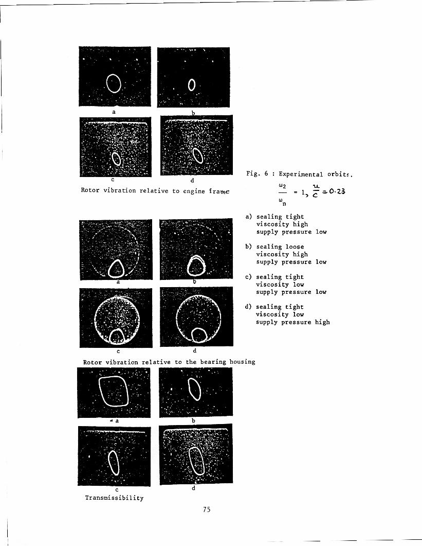
Pre l ix ina ry t e s t s were f i r s t run on the reduced t e s t f a c i l i t y t o a s c e r t a i n whether t hese t r ends were exh ib i t ed i n t h e a c t u a l non-linear system. Various means were adopted by which the e f f e c t i v e daaping could be a l t e r e d . For exaxple , damping could be increased by
i! inc reas ing the o i l v i s c o s i t y ii :) t i gh ten ing the s e a l i n g , o r iii 1 i nc reas ing the s u p p l y pressure .
Figs . 6a, b , c show t h e r e s u l t s ob ta ined f o r var ious s e a l i n g cond i t ions , o i l v i s c o s i t i e s and supply pressures . From t h e s e , conclusions can be drawn which a r e c o n s i s t e n t wi th the th ree d i s t i n c t i v e f e a t u r e s us ing t h e l i n e a r damping nodel. This model thus provides a reasonable q u a l i t a t i v e guide t o damper performance i n the most c r i t i c a l reg ion of r o t o r opera t ion .
The next purpose of t he reduced t e s t f a c i l i t y was t o look f o r evidence of j u p phenomena and sub-hamonic v i b r a t i o n s i n the frequency responses as these had been observed i n c e r t a i n engine t e s t s Gihere the o i l v i s c o s i t y was low.
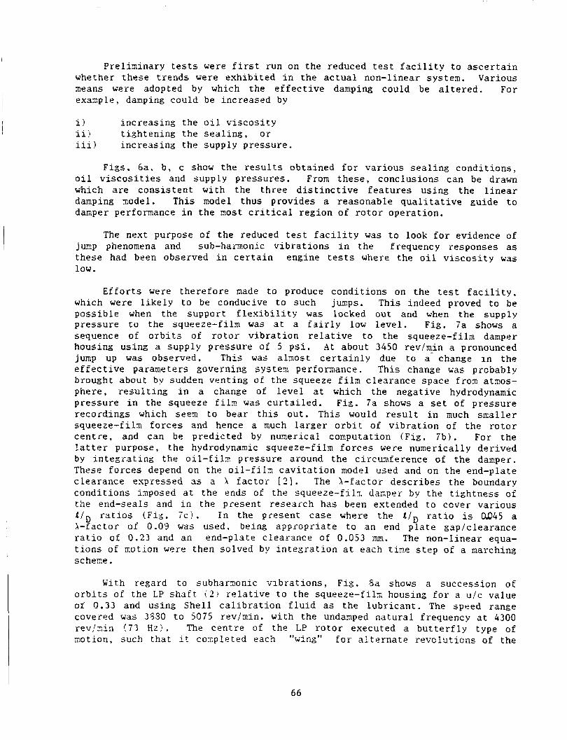
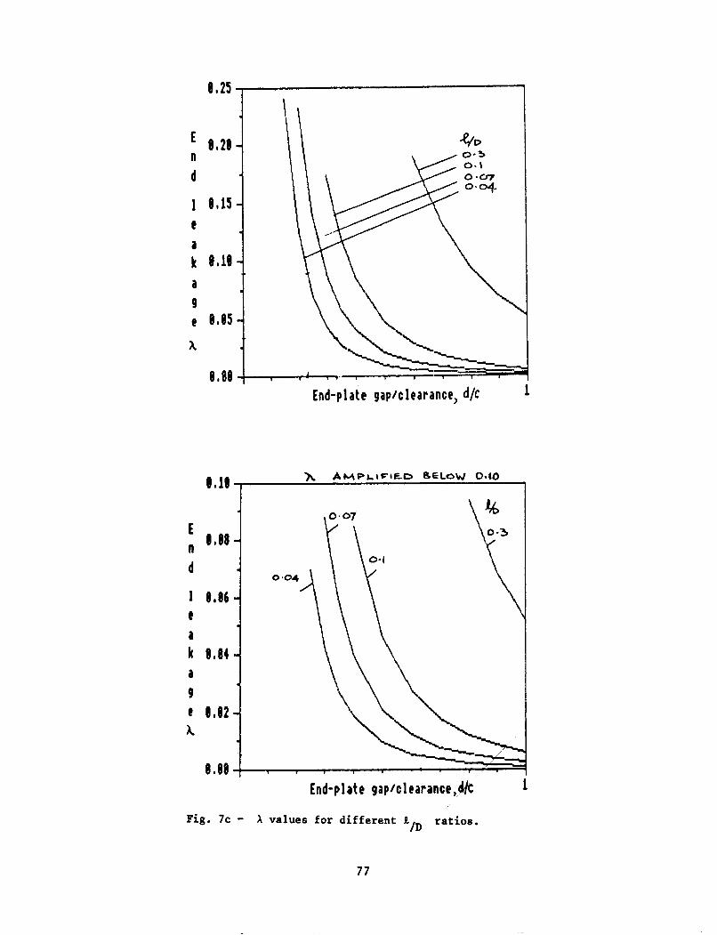
E f f o r t s were the re fo re aade t o produce cond i t ions on the t e s t f a c i l i t y , which were l i k e l y t o be conducive t o such jumps. This indeed proved t o be poss ib l e when the support f l e x i b i l i t y w a s locked out and when t he supply p re s su re t o t h e squeeze-filrr! was a t a f a i r l y low l e v e l . F i g . 7a shows a sequence of o r b i t s of r o t o r v i b r a t i o n r e l a t i v e t o the squeeze- f i ln damper housing us ing a s u p p l y pressure of 5 p s i . A t about 3450 rev/min a pronounced jump up w a s observed. This was a l z o s t c e r t a i n l y due t o a- change i n the e f f e c t i v e parameters governing s y s t e n per foraance . This change was probably brought about by sudden vent ing of the squeeze f i l m c learance space from atmos- phere, r e s u l t i n g i n a change of l e v e l a t which the negat ive hydrodynamic pressure i n the squeeze f i l m was c u r t a i l e d . F i g . 7a shows a s e t of p re s su re record ings which seen to bear t h i s ou t . This would r e s u l t i n much sma l l e r squeeze- f i ln f o r c e s and hence a much l a r g e r o r b i t of v i b r a t i o n of t he r o t o r c e n t r e , and can be p red ic t ed by nuze r i ca l cornputation ( F i g . 7b) . For the l a t t e r purpose, t he hydrodynamic squeeze-fi lm f o r c e s were numerical ly der ived by i n t e g r a t i n g the o i l - f i l n ! pressure around the c i r c m f e r e n c e of t he damper. These f o r c e s depend on the o i l - f i l a c a v i t a t i o n model used and on the end-plate c l ea rance expressed as a X f a c t o r 121 . The \ -€ac to r desc r ibes the boundary cond i t ions ixposed a t the ends of the squeeze- f i ln dazper by the t i g h t n e s s of the end-seals and i n the present research has been extended t o cover var ious a / , r a t i o s (Fig , . 7 c ) . I n the present ca se where the S/, r a t i o is a045 a X-factor of 0.0'3 was used, being appropr i a t e t o an end p l a t e gap/c learance r a t i o of 0 . 2 3 and an end-plate c learance of 0.053 nun. The non-linear equa- t i o n s o f motion were then solved by i n t e g r a t i o n a t each t h e s t e p of a marching scherne.
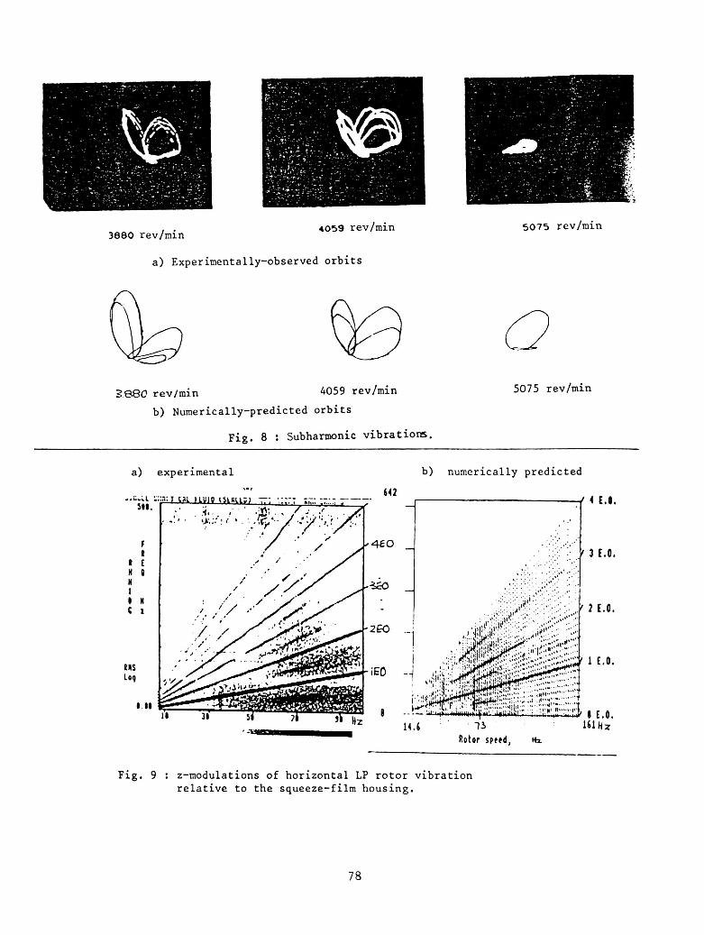
With regard t o subham.onic v i b r a t i o n s , F i g . Sa shows a success ion or' o r b i t s of the LP s h a f t < 2 ! r e l a t i v e t o the squeeze- f i ln housing f o r a u / c value or' 0 . 3 3 and using S h e l l c a l i b r a t i o n f l u i d as the l u b r i c a n t . The speed range covered was 3830 t o 5075 revlmin. with the undamped n a t u r a l frequency a t 4300 revjni:) ( i 3 Hz). The c e n t r e of the LP r o t o r executed a b u t t e r f l y type of no t ion , such t h a t i t co rq le t ed each "winZ=" f o r a l t e r n a t e r evo lu t ions of the
66
r o t o r . This half-engine o r d e r motion p e r s i s t e d over a wide range of opera- t i o n a l speed. Eventual ly t h e "wings" coa lesced a f t e r the c r i t i c a l speed was passed t o produce an e s s e n t i a l l y s i n g l e o r b i t . The p red ic t ed o r b i t s f o r t he same speeds a r e shown i n F i g . ab , i n which the same double looping is c l e a r l y ev ident . Coalescing i s p red ic t ed somewhat l a t e r i n the speed range than was measured.
Z-YODLLATION
The z-mod technique p resen t s a g r e a t dea l of u se fu l i n f o m a t i o n on the harmonic conten t of a s i g n a l i n a very compact way and by t h i s means i t is poss ib l e t o apprec i a t e an o v e r a l l perforinance s i g n a t u r e of an engine over a wide speed range. A Z-siOd is similar t o a "water fa l l " diagram used i n r o t a t i n g machinery d i a g n o s t i c s except t h a t engine speeds a r e arranged along t h e x a x i s , i n s t e a d of a long the y a x i s , frequency content is d isp layed along t h e y a x i s i n s t e a d of a long the x a x i s and the s t r e n g t h of a frequency component is represented as a co lour ( o r as a degree of b lackness) i n s t e a d of a laid-back peak.
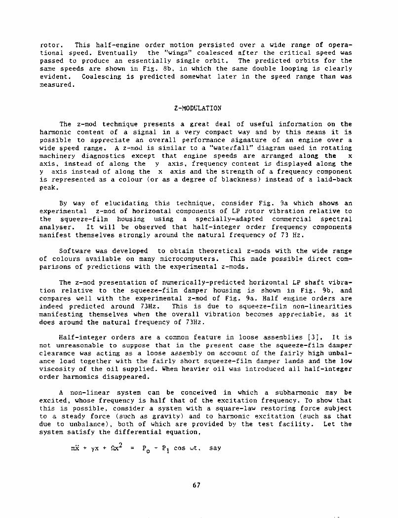
By w a y of e l u c i d a t i n g t h i s technique, cons ide r F i g . 9a which shows an experimental z-mod of ho r i zon ta l components of LP r o t o r v i b r a t i o n r e l a t i v e t o the squeeze-film housing using a spec ia l ly-adapted c o m e r c i a l s p e c t r a l ana lyse r . I t w i l l be observed t h a t h a l f - i n t e g e r o r d e r frequency components manifest theniselves s t r o n g l y around the n a t u r a l frequency of 7 3 Hz.
Software was developed t o o b t a i n t h e o r e t i c a l z-mods wi th the wide range of co lou r s a v a i l a b l e on many microcomputers. This made poss ib l e d i r e c t com- pa r i sons of p r e d i c t i o n s with the experimental z-mods.
The z-mod p r e s e n t a t i o n of nurnerically-predicted h o r i z o n t a l LP s h a f t vibra- t i o n r e l a t i v e t o the squeeze-fi lm damper housing is shown i n F i g . 9b, and coapares wel l wi th the experimental z-mod of F ig . 9a. Half engine o r d e r s a r e indeed p red ic t ed around 73Hz. This is due t o squeeze- f i ln non- l inea r i t i e s mani fes t ing themselves when the o v e r a l l v i b r a t i o n becornes apprec i ab ie , as i t does around t h e n a t u r a l frequency of i3Hz.
Hal f - in teger o r d e r s a r e a comon f e a t u r e i n loose a s s e a b l i e s [ 3 : , I t is not unreasonable t o suppose t h a t i n the present ca se the squeeze- f i ln damper c l ea rance was a c t i n g as a loose assembly on account of t he f a i r l y h igh unbal- ance load toge the r w i t h t he f a i r l y s h o r t squeeze- f i ln damper lands and t h e low v i s c o s i t y of t he o i l supp l i ed . When heavier o i l was introduced a l l ha l f - in t ege r o r d e r harmonics disappeared.
A non-linear systen can be conceived i n which a subharinonic may be e x c i t e d , whose frequency is ha l f t h a t of the e x c i t a t i o n frequency. To show t h a t t h i s is p o s s i b l e , cons ider a systern wi th a square-law r e s t o r i n g f o r c e s u b j e c t t o a s teady fo rce (such as g r a v i t y ) and to harmonic e x c i t a t i o n !such as t h a t due t o unbalance) , both of which a r e provided by the t e s t f a c i l i t y . Let the system s a t i s f y the d i f f e r e n t i a l equat ion ,
mj l + yx + ~2 = P, + p1 cos u t . say
6 7
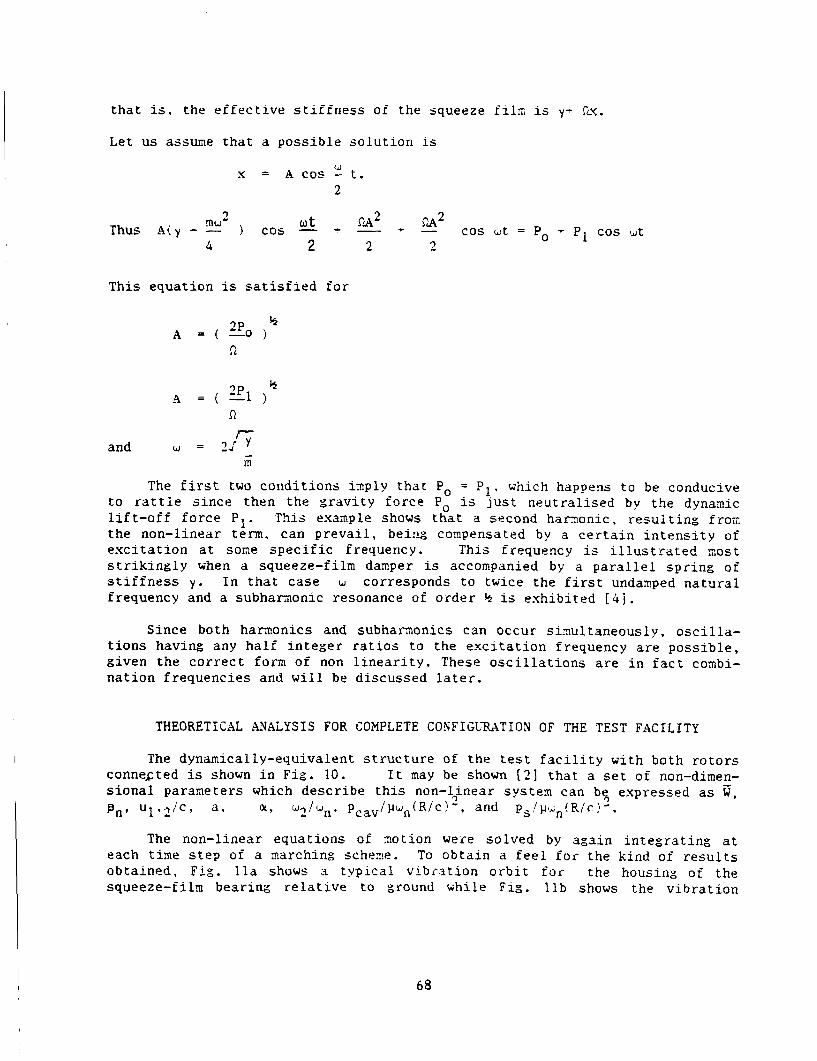
t h a t i s , the e f f e c t i v e s t i f f n e s s of t he squeeze file is y- s f i u .
Let us assume tha t a poss ib l e s o l u t i o n is
IJ x = A cos - t . 2
cos u t = Po + PI cos u t siA2 nu- ) c o s - * - + - ut
7
Thus A ( y - - 4 2 2 2
This equat ion is s a t i s f i e d f o r
n and w = 2 d 5 - m
The f i r s t two cond i t ions t o r a t t i e s i n c e then the gra
i r r p l y t h a t Po = r i t y f o rce P, i
P which happens t o be conducive U l u s t n e u t r a l i s e d by the dynamic
l i f t - o f f f o r c e P I . This exanple shows t h a t a second harxonic , r e s u l t i n g f r o x the non-linear term. can p r e v a i l , bei:i:: compensated by a c e r t a i n i n t e n s i t y of e x c i t a t i o n a t sone s p e c i f i c frequency. This frequency is i l l u s t r a t e d nos t s t r i k i n g l y when a squeeze-fi lm damper is accompanied by a p a r a l l e l s p r i n g of s t i f f n e s s y . I n t ha t case w corresponds t o twice the f i r s t undamped n a t u r a l frequency and a subhamonic resonance of o r d e r h is exh ib i t ed [ 4 j .
1. ’
Since both harnonics and subhamonics can occur s inu l t aneous ly , o s c i l l a - t i o n s having any ha l f i n t e g e r r a t i o s t o the e x c i t a t i o n frequency a r e p o s s i b l e , g iven the c o r r e c t forin of non l i n e a r i t y . These o s c i l l a t i o n s a r e i n f a c t conbi- na t ion f requencies and w i l l be discussed l a t e r .
THEORETICAL LVALYSIS FOR COMPLETE CONFIGUMTION OF THE TEST FACILITY
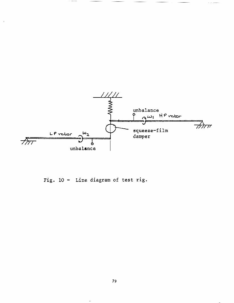
The dynamically-equivalent s t r u c t u r e of t h e t e s t f a c i l i t y w i t h both r o t o r s connected is shown i n F i g . 10. I t may be shown 121 t h a t a s e t of non-dimen- s i o n a l parameters which desc r ibe t h i s non-lfnear systern can be? expressed as G, 8,. u1.2’!c, a, a, w2/un. P ~ ~ ~ / ) J L I ~ ( ~ / ~ ~ ~ * , and ps!~tin!Ric!-.
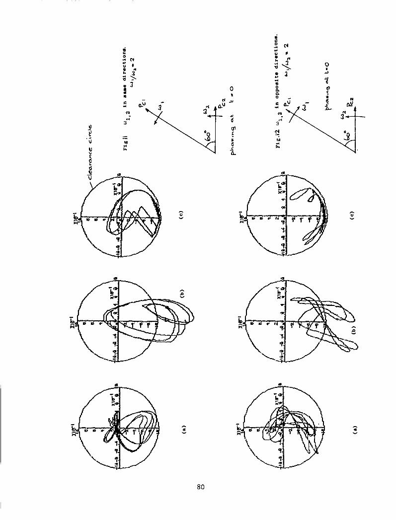
The non-linear equat ions of a o t i o n were so lved by aga in i n t e g r a t i n g a t each t i n e s t e p of a narchin:: s c h w e . To ob ta in a f e e l f o r the kind of r e s u l t s ob ta ined . Fig. l l a shows 3 t yp ica l vibr .2t ion o r b i t f o r the housing of the squeeze-fi lm bear ing r e l a t i v e t o ground while F i g . l l b shows the v i b r a t i o n
68
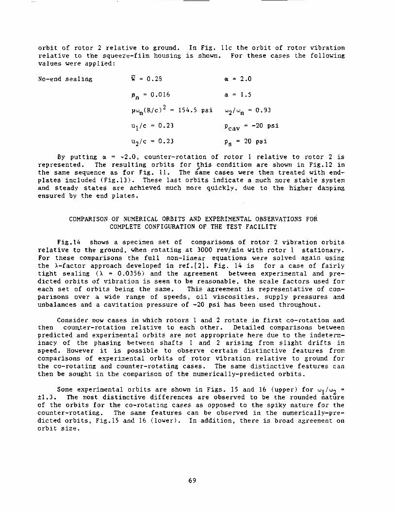
o r b i t of r o t o r 2 r e l a t i v e t o ground. I n F ig . l l c t h e o r b i t of r o t o r v i b r a t i o n r e l a t i v e t o the squeeze-fi lm housing is shown. For these cases the fol lowing va lues were appl ied :
- No-end s e a l i n g w = 0.23 ar = 2.0
pn = 0.016 a = 1.5
) I W ~ ( R / C ) ~ = 154.5 p s i w 2 j U n = 0.93
Ul/C = 0.23 = -20 p s i Pcav
u2/c = 0 . 2 3 ps = 20 p s i
By p u t t i n g ar = -2.0, counter - ro ta t ion of r o t o r 1 r e l a t i v e t o r o t o r 2 is represented . The r e s u l t i n g o r b i t s f o r > h i s cond i t ion a r e shown i n Fig.12 i n the same sequence as f o r F i g . 11. The same cases were then t r e a t e d wi th end- p l a t e s included (F ig .13) . These las t o r b i t s i n d i c a t e a much nore s t a b l e s y s t e m and s t eady s t a t e s a r e achieved much more qu ick ly , due t o t h e h igher daaping ensured by the end p l a t e s .
COMPARISON OF NUXERICAL ORBITS AXD EXPERIMENTAL OBSERVATIONS FOR COMPLETE COWFIGERATION OF THE TEST FACILITY
Fig.14 shows a specimen s e t of comparisons of r o t o r 2 v i b r a t i o n o r b i t s r e l a t i v e t o the ground, when r o t a t i n g a t 3000 rev/min with r o t o r 1 s t a t i o n a r y . For these comparisons the f u l l non-linear equat ions were solved again us ing t h e X-factor approach developed i n r e f . [21 . Fig. 14 is f o r a case of f a i r l y t i g h t s e a l i n g ( X = 0.03563 and the agreement between experimental and pre- d i c t e d o r b i t s of v i b r a t i o n is seen t o be reasonable , t h e s c a l e f a c t o r s used f o r each s e t of o r b i t s being the same. This agreement is rep resen ta t ive of com- pa r i sons over a wide range of speeds , o i l v i s c o s i t i e s , supply p re s su res and unbalances and a c a v i t a t i o n pressure of -20 p s i has been used throughout.
Consider now c a s e s i n which r o t o r s 1 and 2 r o t a t e i n f irst co- ro ta t ion and then couRter-rotat ion r e l a t i v e t o each o the r . De ta i l ed comparisons between p red ic t ed and expe r inen ta l o r b i t s a r e not appropr i a t e here due t o the indeterin- inacy of the phasing between s h a f t s 1 and 2 a r i s i n g from s l i g h t d r i f t s i n speed. However i t is poss ib l e t o observe c e r t a i n d i s t i n c t i v e f e a t u r e s from comparisons of expe r inen ta l o r b i t s of r o t o r v i b r a t i o n r e l a t i v e t o ground f o r the co- ro ta t ing and counter - ro ta t ing cases . The same d i s t i n c t i v e f e a t u r e s can then be sought i n t h e comparison of t he numerical ly-predicted o r b i t s .
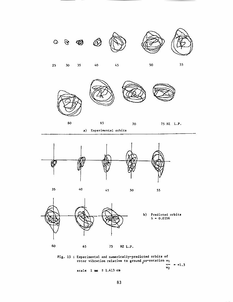
Some experimental o r b i t s a r e shown i n Figs . 15 and 16 (upper ) f o r w1/w2 = 21.3. The xos t d i s t i n c t i v e d i f f e r e n c e s a r e observed t o be the rounded na ture of t he o r b i t s f o r t h e co- ro ta t ing c a s e s as opposed t o the sp iky na tu re f o r t he counter - ro ta t ing . The same f e a t u r e s can be observed i n the numerically-pre- d i c t e d o r b i t s , Fig.15 and 16 ( l o w e r ) . In a d d i t i o n , t h e r e is broad agreement on o r b i t s i z e .
6 9
I t was not iceable dur ing running t h a t the t e s t f a c i l i t y was m c h more noisy f o r counter r o t a t i o n , suggestirig t h a t t r ansmi t t ed f o r c e s were h ighe r , perhaps due t o the more sudden r e v e r s a l s i n t h e o r b i t s .
FREQUENCY CONTENT OF SYSTLY VIBEUTION br3IEN SHAFTS i U E I Y CO-ROTATION AiiD I N COL3TER-ROTATION : COMBINATION FREQUENCIES
I n a l i n e a r s y s t e n resonance occurs uhen t h e systern is e x c i t e d by a har- monic fo rce of frequency near t o t h e undamped n a t u r a l frequency of t he system. I n a non-linear system o t h e r kinds of resonance a r e poss ib l e .
Consider a non-linear system s u b j e c t t o an e x c i t a t i o n c o n s i s t i n g of two harmonic components as we have i n t h i s t e s t f a c i l i t y . Thus.
n.< 7 f(x) = P1 cos (wit O l j 7 P2 cos ! w , t 4 0,) - in whicn we can expand f(x) i n the form or’ a Taylor s e r i e s .
7 f ( x ) = alx + a2x- + a3x3 + ...
x = XI cos W l t - s* cos J2t Now assume t h a t x is roughly harmonic, t h a t is
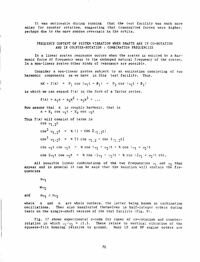
Thus f(x) w i l l c o n s i s t of t e r n s i n cos w1 ,t
9 -
3 cos- W 1 , 2 t = h ( 1 - cos 2 . J l , , t )
cos W l t c o s u p -- b cos !w1 -I- w 2 ) t .r h cos i d l - W,!t -
A l l poss ib l e l i n e a r combinations of the two f requencies !dl and w2 thus appear and i n gene ra l i t can be s a i d t h a t t he s o l u t i o n w i l l con ta in the f r e - quenc i e s
and nwl f mw2
where in and n a r e whole nunbers . the l a t t e r being known as coxbinat ion o s c i l l a t i o n s . They a l s o manifested t h e m e l v e s i n ha l f - in t ege r o rde r s during t e s t s on the s ing le - sha f t ve r s ion of the t e s t f a c i l i t y ( F i g . 9!.
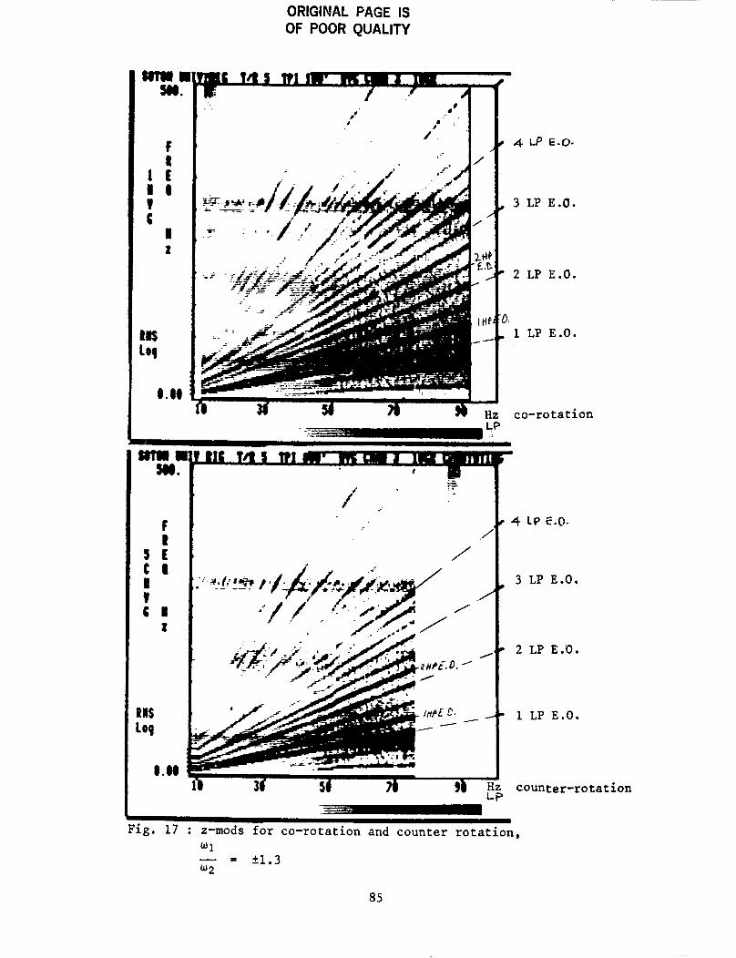
F i g . 17 shows expe r ixen ta l z-cads f o r c a s e s of co- ro ta t ion and counter- r o t a t i o n i n which wliw2 = 51.3. These r e l a t e t o v e r t i c a l v i b r a t i o n or‘ the squeeze-fi lm housing r e l a t i v e t o ground. Yany L? and IiP engine o rde r s a r e
70
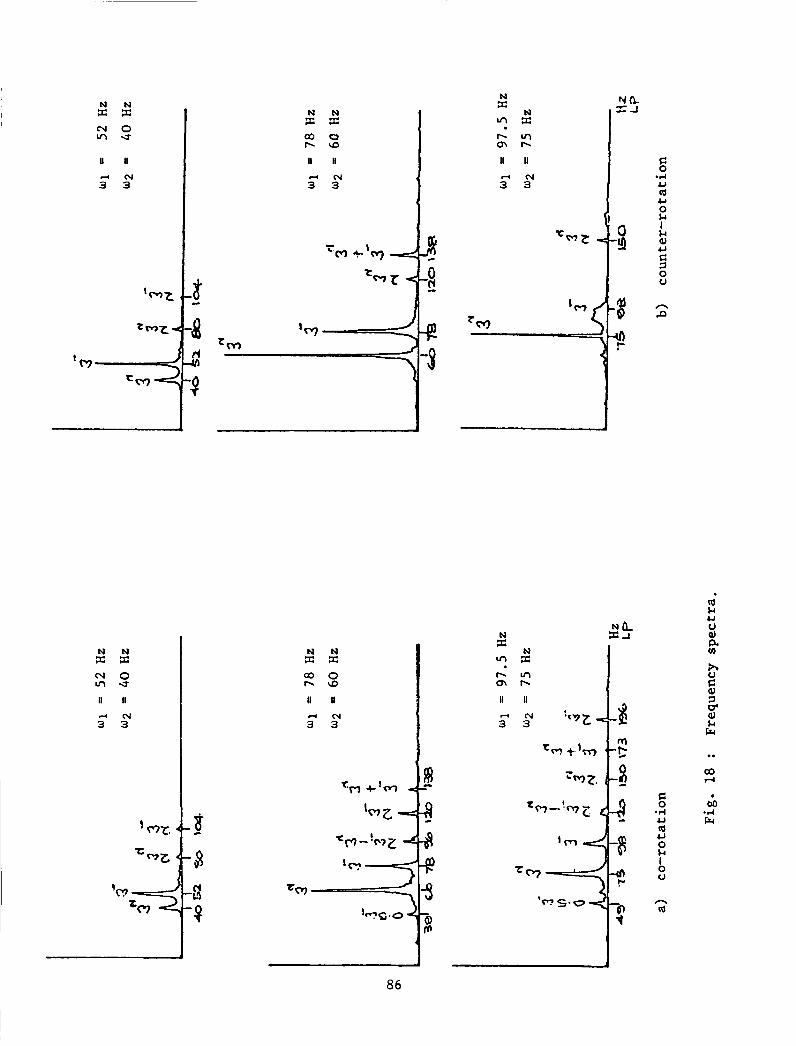
present i n both. as a r e probable combination f requencies . By t ak ing a v e r t i c a l s e c t i o n of the z-mod a t L.P. r o t o r speeds of s a y 4 0 , 60 and 7 5 r e v i s , frequency s p e c t r a can be cons t ruc ted . F i g s . lSa , b show such s p e c t r a f o r co- ro ta t ion and counter - ro ta t ion r e spec t ive ly . Some sugges t ions a r e made on F i g . 13 as t o what t hese f requencies might be i n terms of HP and LP r o t o r speeds.
CONCLCSIONS
The purpose of the research descr ibed i n t h i s paper has been t o reproduce on a t e s t f a c i l i t y phenomena exh ib i t ed i n aero-engine t e s t s . These included subhannonic o s c i l l a t i o n s , jumps i n frequency response and combination frequen- c i e s . A 1 1 of these e f f e c t s were reproduced and could be p red ic t ed by numerical computation o r by apprec i a t ion of non-linear mechanics. Furthernore. a t speeds i n t h e v i c i n i t y of the undanped n a t u r a l frequency, a l i n e a r t r e a t n e n t gave a sound understanding of t r ends i n v i b r a t i o n performance.
A method was presented by which the above f e a t u r e s could be apprec ia ted i n a conprehrnsive w a y . This is known as the z-aodulation technique and u t i l i s e s up-to-date computer graphics f a c i l i t i e s .
R E F E R E X E S
[ l ] Holmes, R . and Dogan. M. ' I n v e s t i g a t i o n of a r o t o r bear ing asse2hly inco rpora t ing a squeeze f i l m damper bear ing . ' Proc. I n s t n . Zech. Engrs. v o l . 2 4 , No. . 3 , 1932.
[ 2 ] Holses , R and Dogan, M . 'The performance of a s e a l e d squeeze-film bearing i n a f l e x i b l e support s t r u c t u r e . ' Proc. In s tn . Mech. Engrs . vo l . 199, No. C1. 1935.
[ 3 ] Angelo, M. 'V ibra t ion Monitoring of Nachines. Bruel nd Kjoer Technical Review 30. 1 1387, pp.5,6.
141 Xikola jsen , J . L . and Holaes. R. ' I n v e s t i g a t i o n of squeeze-film i s o l a t o r for the vibration c o n t r o l of a flexible r o t o r . ' Proc. i n s t n . NYlech. Engrs. v o l . 2 1 . ?io. 4 , 1979.
71
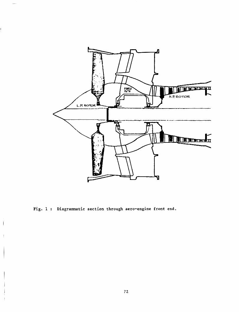
Fig. 1 : Diagrammatic section through aero-engine front end.
72
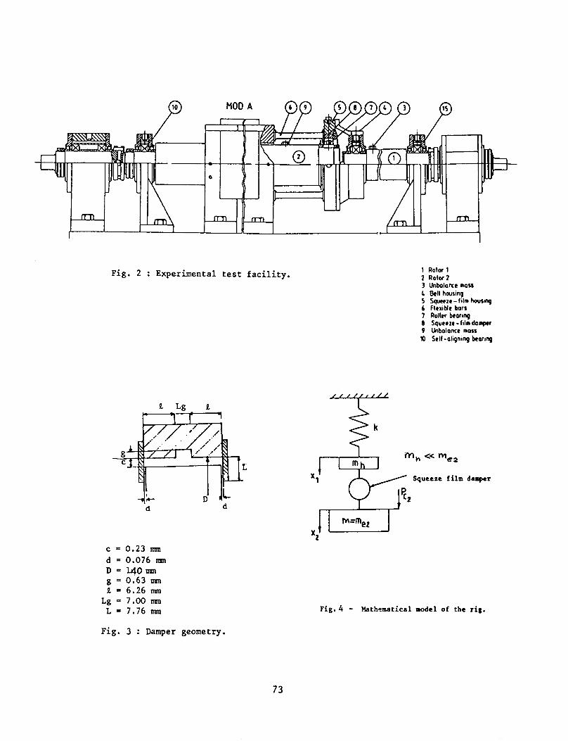
Fig. 2 : Experimental test facility.
9. Lg a
c = 0.23 m d = 0.076 nun D = l 4 O m g = 0.63 m 1 = 6.26 m
Lg - 7.00 mm L = 7.76 mm
1 Rotor 1 2 Rotor2 3 Unbolonce moss L Bell housing 5 Sguccze - fi lm howq 6 flexiblc bors 7 Roller beorinp 0 Squeeze -fi lm domprr 9 Unbalance moss 10 Self -aligning korinp
Fig. 4 - Mathematical model of the r ig .
Fig. 3 : Damper geometry.
73
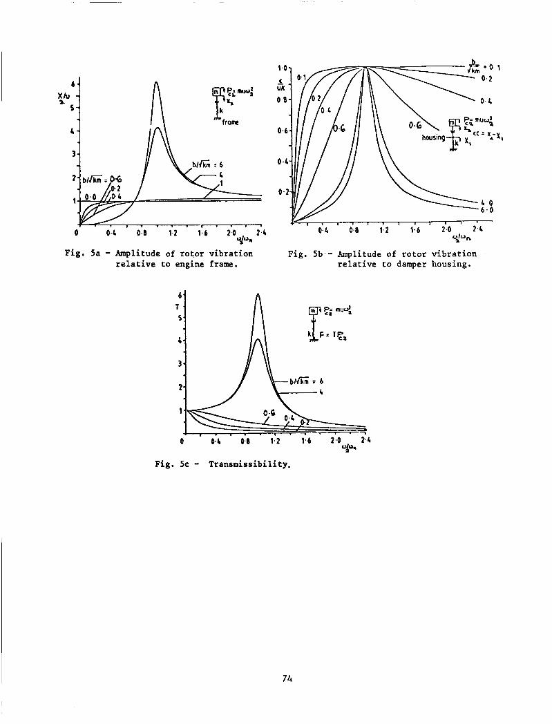
Fig. 5a - Amplitude of rotor vibration relative to engine frame.
1 . 1 . 1 1 I ~ ' '
0.2 0.8 1.2 1.6 2.0 2.4 O h ,
relative to damper housing.
a
Fig. 5b.- Amplitude of rotor vibration
Fig. 5c - Transmissibility.
74
a
Rotor vibration relative to engine frame
C
w2 u - = F=0*23 w n
d
Rotor vibration relative to the bearing housing.
b
C
Transmissibility d
75
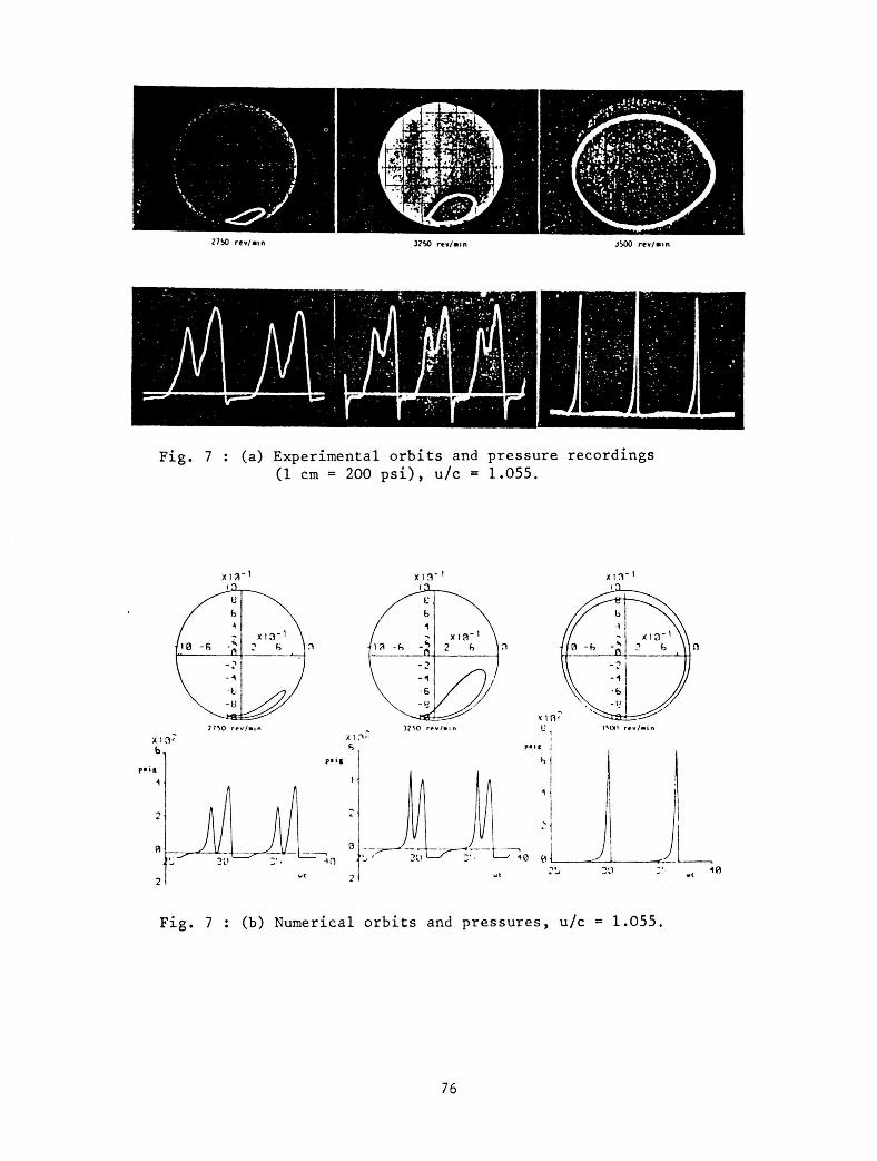
Fig. 7 : (a) Experimental orbi ts and pressure recordings (1 cm = 200 p s i ) , u/c = 1.055.
Fig. 7 : (b) Numerical orbits and pressures, u/c = 1.055.
76
I \
End-pl at e gap/clearance, d/c 1
elea E n d
e a k 0104
a 9 e 0102
h
e a 0 8 . End-plate gap/clearance ,& 1
Fig. 7c - X values for different a,, ratios.
77
~~
3880 revlmin 5075 revlrnin
a) Experimentally-observed orbits
3880 revjmin 4059 rev/min
b) Numerically-predicted orbits
Fig. 8 : Subharmonic vibratiom.
Q 5075 revhin
a) experimental b) numerically predicted
642
zm
iEO
a
I E,O.
3 1.0,
2 1.0.
I E.O.
8 1.0. 1 4 . 6 73 z 1 6 1 ~ ~
Rotor speed, t+a
Fig. 9 : z-modulations of horizontal LP rotor vibration relative to the squeeze-film housing.
78
2 unb a1 anc e
J
L Q Mkf damper
unbalance I
Fig. 10 - Line diagram of test rig.
7 9
0 I
3
U 3
!?
. -
S
n 0 Y
a
n (I "
A
v (I
80
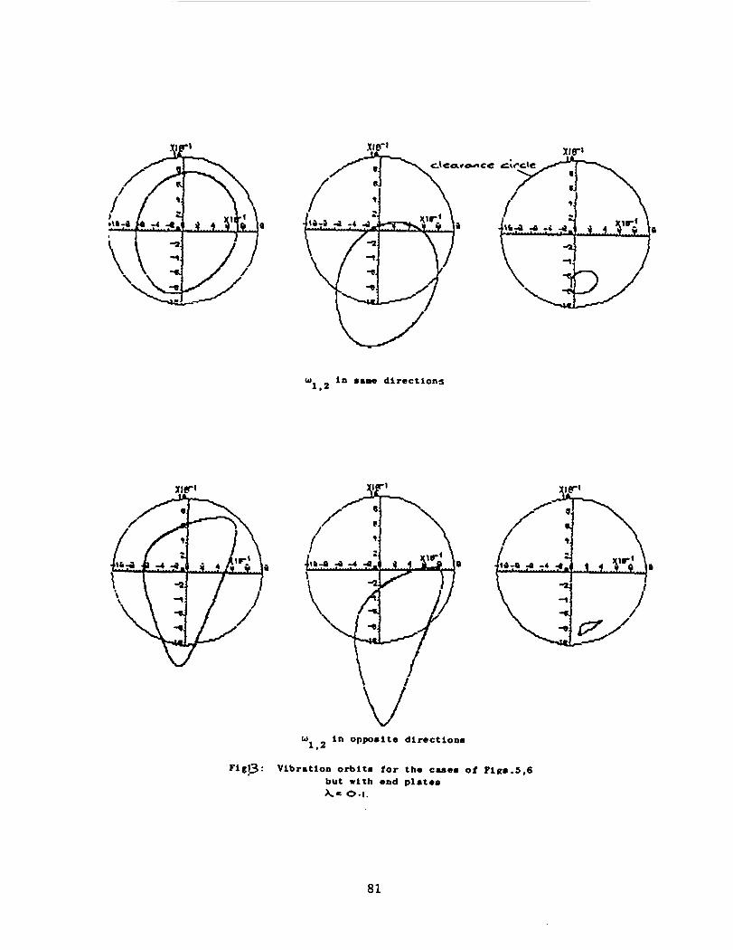
w in name d i r e c t i o n s 1.2
w i n Opposite d i r e c t i o n s 1 . 2
F i g p : Vibration orbit. f o r the cmes of P i g 8 . 5 , 6 but with end plate . A= 0 . 1 .
81
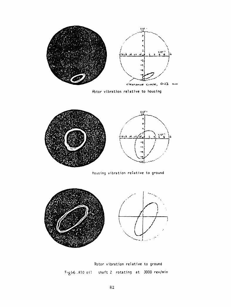
&tor v i b r a t i o n r e l a t i v e t o housfng
nousing v i b r a t i o n r e l a t i v e t o ground
Rotor v i b r a t i o n r e l a t i v e t o ground
F i g \ 4 . R l O o i l s h a f t 2 r o t a t i n g a t 3000 rev/min
a2
0
25
B
30 35 40 45 50 55
60 65 70 75 HZ L . P .
a) Experimental orbits -
35 40 4 5 50 55
b) Predicted orbits X - 0.0356
6 0 65 75 HZ L.P.
Fig. 15 : Experimental and numerically-predicted orbits of rotor vibration relative to ground > co-rotation ~1
- - +1.3 W 2
scale 1 IIQ I 1.413 cm
83

5 30 35 40 50
a) Experimental orbits
70 75 Hz L . P .
40 45 I 1 50 55 60
1
65 70 75 80 HZ L . P .
b) predicted orbits , A = 0.0356
Fig. 16 : Experimental and numerically-predicted orbits of rotor vibration relative to ground counter-rotation, 2 I
scale 1 nun f 1.413 cm
-1.3 > w 2
8 4
ORIGINAL PAGE IS OF POOR QUALITY
m a m.
F t
1 E I @ t C I 2
tlcs 109
0.04
___ LP - __
m a m.
F t
s t C I I v C I
2
R l S 109
0.04
r Fig. 17 : z-mods for co-rotation and counter rotation,
i ...
_- e F .-
,/
/
' 4 Lp E.O.
, 3 LP E.O.
' 2 LP E.O.
3. , 1 LP E.O.
co-rotation
I
4 LP E.0-
3 LP E.0.
2 LP E.0 .
1 LP E.O.
counter-rotation
2 2 N O m e
u II
4 t Y 3 3
N N x x N O m u II II I
N N x x a 0 - \ D
u u
4 t Y 3 3
N m x 2
N L X d
g .I4 & a & 0 k I k al &
0 U
n P
a &I u 0 al a u)
k Frc
.. co rl
a & 0 k I 0 0
n a
86