The sound of communication in underwater acoustic sensor ...
15
HAL Id: hal-01699521 https://hal.archives-ouvertes.fr/hal-01699521 Submitted on 2 Feb 2018 HAL is a multi-disciplinary open access archive for the deposit and dissemination of sci- entific research documents, whether they are pub- lished or not. The documents may come from teaching and research institutions in France or abroad, or from public or private research centers. L’archive ouverte pluridisciplinaire HAL, est destinée au dépôt et à la diffusion de documents scientifiques de niveau recherche, publiés ou non, émanant des établissements d’enseignement et de recherche français ou étrangers, des laboratoires publics ou privés. The sound of communication in underwater acoustic sensor networks Michel Barbeau, Joaquin Garcia-Alfaro, Evangelos Kranakis, Steven Porretta To cite this version: Michel Barbeau, Joaquin Garcia-Alfaro, Evangelos Kranakis, Steven Porretta. The sound of commu- nication in underwater acoustic sensor networks. ADHOCNETS 2017: 9th International Conference on Ad Hoc Networks, Sep 2017, Niagara Falls, Canada. pp.13 - 23, 10.1007/978-3-319-74439-1_2. hal-01699521
Transcript of The sound of communication in underwater acoustic sensor ...

HAL Id: hal-01699521https://hal.archives-ouvertes.fr/hal-01699521
Submitted on 2 Feb 2018
HAL is a multi-disciplinary open accessarchive for the deposit and dissemination of sci-entific research documents, whether they are pub-lished or not. The documents may come fromteaching and research institutions in France orabroad, or from public or private research centers.
L’archive ouverte pluridisciplinaire HAL, estdestinée au dépôt et à la diffusion de documentsscientifiques de niveau recherche, publiés ou non,émanant des établissements d’enseignement et derecherche français ou étrangers, des laboratoirespublics ou privés.
The sound of communication in underwater acousticsensor networks
Michel Barbeau, Joaquin Garcia-Alfaro, Evangelos Kranakis, Steven Porretta
To cite this version:Michel Barbeau, Joaquin Garcia-Alfaro, Evangelos Kranakis, Steven Porretta. The sound of commu-nication in underwater acoustic sensor networks. ADHOCNETS 2017 : 9th International Conferenceon Ad Hoc Networks, Sep 2017, Niagara Falls, Canada. pp.13 - 23, 10.1007/978-3-319-74439-1_2.hal-01699521

The Sound of Communication in UnderwaterAcoustic Sensor Networks?
(Position Paper)
Michel Barbeau1, Joaquin Garcia-Alfaro2, Evangelos Kranakis1, and StevenPorretta1
1 School of Computer Science, Carleton University, Ottawa, ON, Canada, K1S 5B6.2 Telecom SudParis, CNRS Samovar, UMR 5157, Evry, France.
Abstract. The interdisciplinary understanding required for the designand analysis of underwater acoustic sensor networks presents formidableconstraints and challenges for computer scientists and engineers. How-ever, underwater environments have never been much of a constraint tothe rich animal life they support at all depths of our seas and oceans.Indeed, it is known that nature has taken advantage of this environmentto develop a rich variety of efficient communication strategies through-out the long history of evolutionary change and adaptation. The wealthof knowledge to be discovered will continue to dazzle and fascinate theworld. For the communications in underwater sensor networks, acousticsignaling is the preferred choice for designers because sound propaga-tion is the most efficient when compared to other forms, like thermal,light, and electromagnetic. It is within this acoustic environment thatresearchers have to innovate and develop new ideas and methodologiesso as to advance the state-of-the-art. In this position paper, several fun-damental issues and connections are discussed that arise in the studyof underwater wireless sensor networks. Throughout the nature of theunderwater environment is emphasized how one can take advantage ofit. A variety of ideas and solutions that could be of value for furtherresearch is proposed. Moreover, fundamental issues in topology control,directional underwater transducers, and monitoring and surveillance arediscussed.Key words: Underwater acoustic communications, directional hydrophoneand vibrator, monitoring and surveillance, neighbour discovery, under-water acoustic sensor network, sub-surface communications.
1 Introduction
Sound is very important for communication in the animal world. It helps ani-mals to become aware of events that occur all around, regardless of where at-tention is focused. With respect to their land counterparts, sea mammals areeven more dependent on sound for communication and sensing because of the
? The research of Michel Barbeau and Evangelos Kranakis is supported in part byNatural Sciences and Engineering Research Council (NSERC) Discovery grants.

special circumstances involved in the nature of signals underwater affecting thepropagation of light, smell, and other senses. One must take into account thatlight propagation suffers from scattering due to reflection and refraction. Smellis affected by molecular diffusion due to temperature, viscosity of the fluid, andsize of the particles. As a consequence, sight and smell could be ineffective andrather much less suited for communication in the seas when compared to sound.Sound has another advantage because water molecules lose less energy as theyvibrate.
This paper explores how sound can be used to effectively communicate andbuild underwater networks. In Section 2, we introduce the nature of sound in theunderwater environment. We explore the transmission of messages using soundin Section 3. A model for directional underwater communications is presentedin Section 4. We conclude in Section 5.
2 Nature of Communication Underwater
You can calculate the speed v (m/s) of sound by taking the square root of theratio of the pressure p (Pa) of the medium, inside which it travels, divided bythe density ρ (kg/m3) of this medium, namely
v =
√p
ρm/s. (1)
In the air, it is approximately only 343 m/s (at sea level). However, despitethe fact that the propagation of sound underwater is affected by temperature,salinity, hydrostatic pressure and other factors, its speed in the ocean variesfrom 1,450 m/s to 1,540 m/s. It is more than four times higher than its speedin the air. Also note how pressure affects the speed of sound. Approximately 1,6m/s per 100 meters downwards is added to the velocity due to the increase inhydrostatic pressure.
Mammalian evolution has created numerous adaptations so as to exploitthe propagation of sound underwater. Acoustic communication in the seas isentirely different from the more familiar terrestrial. Moreover, in marine life,mechanisms used to produce sound vary widely even from one family of seaanimals (such as whales, dolphins, and porpoises) to another. This is documentedextensively in the scientific marine biology literature. For example, it is wellknown that the humpback whales are producing regular and predictable soundsknown as songs to communicate male fitness to females. The clicking sequences ofdolphins and sperm whales are thought to be individualized rhythmic sequencescommunicating the identity of a single mammal to others in its group. Theyallow groups to coordinate foraging activities. Furthermore, communication canreach large distances with sperm whales being the undisputed vocal championsthat can give a powerfully deafening directional sonar of 240 dB.
One cannot but marvel at the astonishing variety of sound based communica-tion mechanisms that have evolved throughout sea life to communicate, attractmates, defend territory, sense surroundings and find food [4, 5, 8, 13]. See Ref. [24]
where you can play recordings of all kinds of underwater animals, from whalesand shrimps to oysters. Although whales can communicate long distance withtheir powerful sounds, at the opposite scale S. Patek [26, 31] reports that thespiny lobster emits Near Field Communication (NFC) signals (that propagateno more than a meter) every time it throws off its exoskeleton. The very uniquesound it generates (by using its body as a violin) protects the naked lobsteragainst its enemies while at the same time the short distance of propagationprevents it from advertising its presence further away!
Underwater communication is not limited to sound. There are numerous sur-prising facts everywhere in the sea world. Electrical eels may have very pooreyesight, but they can stun their prey with their powerful electrical pulses liketaser guns [8]. Turtles seem to inherit instructions for navigating through theearth’s weak magnetic fields, travel long distances and return to their place oforigin essentially performing a form of compass routing through the isoclinicsand isodynamics of the earth’s magnetic maps [22]. Also take note that magneticnavigation has the advantage that it works even in deep oceans where light isimpossible to penetrate. In Australia, the archerfish (Toxotes chatareus) is anexpert physicist in that it calculates the precise angle for shooting from insidethe water to the air despite refraction to kill its prey [8]. Certain families ofsquid not only have directional antennae communication, but can also commu-nicate with each other using their own morse code(see video in [21]). With theirwonderful multicolor displays and convulsions, octopuses can match the color oftheir bodies instantaneously to their environment [10], presumably to transmitmessages.
3 Transmission of Sound
What technical issues do we encounter in transmitting messages underwater?How can we take them into account and at the same time improve our commu-nication capabilities? In this section, we discuss how sonar measurements aremade underwater as well as the impact of waveguides (communication tunnels)for connectivity.
3.1 Sonar Measurements
Sonar (also called echolocation) refers to the principle of detecting and localizingobjects by sound. When referring to animals, it is also called biological sonaror biosonar. Unlike the discovery of sonar in bats, which happened as early as1773 (due to the Italian scientist Lazzaro Spallanzani), the discovery of sonarin dolphins did not occur until 1947 (due to Arthur McBride, the first curatorof Marine Studios, in Florida). SONAR is an acronym for SOund NavigationAnd Ranging [3]. It is a technique that uses underwater sound propagation tonavigate, communicate with or detect objects (such as submarines and mines) onor under the surface of the water by projecting sound and detecting the echoesfrom the objects.

The key to measuring the intensity and pressure of acoustic waves is basedon using the concept of decibel (dB). Since in underwater acoustics, the primaryinterest is often in ratios rather than in absolute quantities this gives a convenientway for expressing changes (usually large) in pressure. Given two powers P1 andP2 (Watts), with power ratio P1/P2, we use the decibel expression as given bythe formula
10 log10
(P1
P2
)dB. (2)
When an acoustic wave propagates in a medium, acoustic energy is being trans-mitted. The amount of energy per second crossing a unit area is called theintensity of the wave. The unit of intensity in underwater acoustics is defined asthe intensity of a plane wave having a pressure p of one micropascal (µPa). Therelationship between acoustic pressure p and intensity I (Watts/m2) is given bythe formula
I =p2
ρvWatts/m2, (3)
where ρ (kg/m3) is the density of water and v (m/s) is the speed of sound.The intensity ratio I1/I2 is defined in decibels similarly to the power ratio,
i.e., the intensity ratio in dB is equal to
10 log10
(I1I2
)dB.
The basic measurement in acoustics is based on pressure and not on intensity.Most hydrophones used in underwater measurements are sensitive to pressure,particle velocity, or pressure gradient. It follows from Equations (2) and (3) thatthe pressure ratio in decibels is expressed as 20 log10(P1/P2).
3.2 Impact of Temperature and Pressure on Sound
Underwater, propagation of sound is three dimensional. It propagates in all di-rections from its source. During transmission sound dissipates. Further, under-standing its behaviour is complicated by such features as suspended particles,air bubbles, plankton, and even the swim-bladders of swimming fish.
The speed of sound in the ocean varies, see Equation (1). It depends ontemperature, salinity, pressure and other factors. Note that the pressure p(z)(µPa) is monotone increasing as a function of the depth z (m). Also temperatureaffects the speed v(z) of sound, as a function of the depth z. The interplay of thesetwo factors affect v(z) that has a representation resembling the plot depictedin the left part of Figure 1. Closer to the surface, the speed v(z) of sound ismore affected by temperature. It decreases as we move deeper. As we moveeven deeper, the impact of pressure overtakes temperature. The speed of soundincreases. Eventually, temperature and pressure balance out at a certain depthzmin. The resulting speed of sound v(zmin) at zmin is the minimum possible. Thisdepth zmin also depends on the oceanic temperature. It can be up to 2 kilometersin warmer waters while it is closer to the surface in the Arctic.
z
v(z)
Bottom
Surface
zmin
z
v(z)
Bottom
Surface
zmin
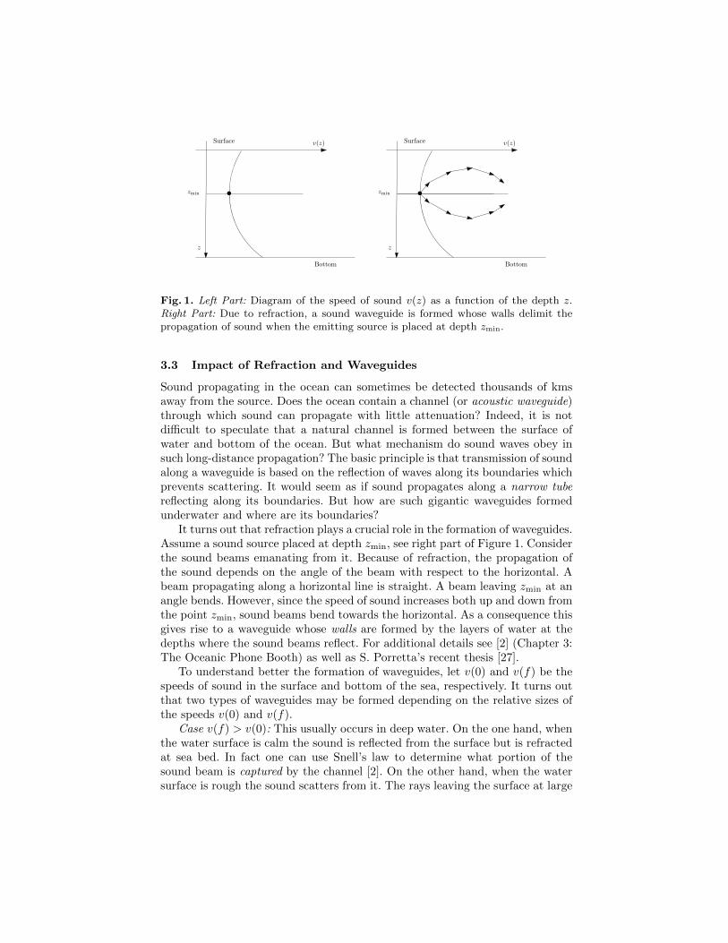
Fig. 1. Left Part: Diagram of the speed of sound v(z) as a function of the depth z.Right Part: Due to refraction, a sound waveguide is formed whose walls delimit thepropagation of sound when the emitting source is placed at depth zmin.
3.3 Impact of Refraction and Waveguides
Sound propagating in the ocean can sometimes be detected thousands of kmsaway from the source. Does the ocean contain a channel (or acoustic waveguide)through which sound can propagate with little attenuation? Indeed, it is notdifficult to speculate that a natural channel is formed between the surface ofwater and bottom of the ocean. But what mechanism do sound waves obey insuch long-distance propagation? The basic principle is that transmission of soundalong a waveguide is based on the reflection of waves along its boundaries whichprevents scattering. It would seem as if sound propagates along a narrow tubereflecting along its boundaries. But how are such gigantic waveguides formedunderwater and where are its boundaries?
It turns out that refraction plays a crucial role in the formation of waveguides.Assume a sound source placed at depth zmin, see right part of Figure 1. Considerthe sound beams emanating from it. Because of refraction, the propagation ofthe sound depends on the angle of the beam with respect to the horizontal. Abeam propagating along a horizontal line is straight. A beam leaving zmin at anangle bends. However, since the speed of sound increases both up and down fromthe point zmin, sound beams bend towards the horizontal. As a consequence thisgives rise to a waveguide whose walls are formed by the layers of water at thedepths where the sound beams reflect. For additional details see [2] (Chapter 3:The Oceanic Phone Booth) as well as S. Porretta’s recent thesis [27].
To understand better the formation of waveguides, let v(0) and v(f) be thespeeds of sound in the surface and bottom of the sea, respectively. It turns outthat two types of waveguides may be formed depending on the relative sizes ofthe speeds v(0) and v(f).
Case v(f) > v(0): This usually occurs in deep water. On the one hand, whenthe water surface is calm the sound is reflected from the surface but is refractedat sea bed. In fact one can use Snell’s law to determine what portion of thesound beam is captured by the channel [2]. On the other hand, when the watersurface is rough the sound scatters from it. The rays leaving the surface at large

angles reach the bottom and are absorbed there. However, because of refractionthe channel captures those rays that do not reach the rough surface [2].
Case v(f) < v(0): This usually occurs in shallow water. In this case the soundrefracted at the bottom does not reach the surface [2].
Schmidt and Schneider [14, 29, 30] documented the existence of a waveguidein the Beaufort Sea, called the Beaufort Lens. Due to a flow of warm water enter-ing through the Bering Strait, from the Pacific Ocean. A sound speed minimumis created at low depth, around 80 m. Sound energy is trapped in the resultingwaveguide. Long range (100 kilometers) communication, without ice interaction,is possible using the waveguide.
Fig. 2. Sound speed profile with local minimum.
The principle can be studied through simulation. Figure 2 shows a SoundSpeed Profile (SSP), artificially created to better illustrate the idea. It plots thespeed of sound (x-axis) as a function of depth (y-axis). There is a sound speedminimum at 500 meter deep. This minimum creates a waveguide in which theacoustic energy propagates without interaction with sea surface or sea bed. Fig-ure 3 shows the result of a BELLHOP [28] simulation of the waveguide at theacoustic signal frequency 50 Hertz. The source-receiver separation distance isfrom zero to 100 kilometers. The x-axis represents range (m). The y-axis rep-resents depth. A signal source is placed on the left, at range zero and depth500 m. On a dB scale, color-coding represents signal attenuation as a functionof location. In underwater, attenuation is proportional to frequency. Hence, at-tenuation is weaker on the left, staring at 70 dB on short range. The simulationsdemonstrate that signals propagating through a waveguide theoretically persistacross long distances.
In conclusion, waveguides are an important component of establishing un-derwater communication. This, of course, should not come as a surprise giventhat also a similar phenomenon occurs in long-distance broadcasting from radio

Fig. 3. Transmission loss (dB) versus distance and depth, at 50 Hertz and from zeroto 100 kilometers.
stations. In fact, this is made possible only because of the propagation of radiowaves through the atmosphere along giant waveguides.
4 Directional Underwater Transducers
Directional antennae are widely used in wireless communication. They are ver-satile. They improve overall energy consumption [18]. This is rather easy tomotivate. The transmission cost is proportional to the area covered by the an-tenna. Thus, the energy cost of an omnidirectional antenna with range r (m) isproportional to the area of a disk of radius r, that is, πr2 m2. By comparisonthe signal from a directional antenna of beam-width φ radians reaches muchfurther, with the same energy consumption, namely it has range r
√2π/φ m
that, depending on the beam-width φ, can be significantly larger than r. Theyhave numerous applications. They may enhance network capacity [12, 33], reachfurther than omnidirectional antennae for detection and surveillance purposes,improve topology control and stability [11], and offer the potential for mitigatingvarious security threats [15], just to mention a few applications.
A significant amount of research has been dedicated to the 2D model ofdirectional antennae. In this model, the antennae are located in a planar ter-rain. To establish a network, antennae need to communicate with each other. Tothis end, two basic antennae communication models are employed. Consider twodirectional antennae: a sender and a receiver. In the symmetric model, communi-cation is possible if the sender and receiver are within the range (determined by

respective lobes) of each other, see [1, 23]. In the asymmetric model, the sendercan transmit directly a message to the receiver (provided the receiver is withinthe range of the sender) but the receiver may not be able to send directly amessage to the sender, see [6, 9, 17, 20]. In a way, the asymmetric model is lessrigid than the symmetric one, but the receiver must seek a (alternate) path inthe network if it also wants to talk to the sender.
4.1 3D Underwater Transducer Model
Underwater communications differ from classical wireless. Rather than electro-magnetic waves, mechanical acoustic waves are used. The transducers, convert-ing electrical energy to mechanical energy and vice versa, are vibrators and hy-drophones. Transmission is done with mechanical vibrators. Reception is donewith mechanical hydrophones. Hereafter, we discuss a 3D underwater transducermodel. We identify vibrators and hydrophones. We model a three dimensional
Fig. 4. Spherical underwater transducer radiation patterns. Solid (represented by Ω)and apex (represented by 2θ) angles in the 3D directional antenna model. The antennain the left picture has a single lobe while in the right picture it has a double lobe.
directional underwater transducer as a spherical sector of solid angle Ω (Fig-ure 4, left) and apex 2θ (Figure 4, right). The solid angle Ω of a solid sphericalsector is defined as the ratio of the area of the spherical surface and square ofthe radius of the sphere of which it forms part. The apex angle of a sphericalsector with solid angle Ω is defined as the maximum planar angle between anytwo generatrices of the spherical sector. It is usually represented by 2θ, see [16]for additional details. The apex 2θ and solid angle Ω are related by the followingimportant identity due to Archimedes.
Ω = 2π(1− cos θ). (4)

To see its validity note that, for a sphere of radius r, the area of the sphericalcap satisfies
Ω =
∫ 2π
0
∫ θ
0
r2 sin θ′ dθ′ dφ = 2πr2∫ θ
0
sin θ′ dθ′ = 2πr2 (1− cos θ)
Archimedes’ Formula (4) gives a method to compute a 3D angle with the helpof a 2D angle, see [32].
4.2 Communication Model
A B
Fig. 5. Symmetric communication with two directional underwater transducers cen-tered at points A and B.
How can we model communication using directional underwater transduc-ers? We distinguish two types of connectivity: symmetric and asymmetric. Insymmetric communication, two underwater transducers communicate if they arewithin range of each other, see Figure 5. This also means they can send messagesdirectly to each other. Contrast this with asymmetric communication (Figure 6)
S R
Fig. 6. Aymmetric communication with directional underwater transducers: A directedcommunication path from the vibrator S to the hydrophone R.
in which a vibrator S can talk to a hydrophone R only if there exists a sequenceof (vibrator, hydrophone) pairs S → S′ such that
S := S1 → S2, S2 → S3, . . . , Sk−1 → Sk := R

and moreover so that each hydrophone in this sequence is within the rangeof a vibrator. Thus, to establish bidirectional communication between S,R inthe asymmetric communication model not only a path must be found betweensource S and destination R; in addition, a path must be found in the reversedirection from destination R to source S. Despite this difficulty it is still possibleto provide algorithms that can establish bidirectional communication [6, 9, 17,20] with constant stretch factor.
4.3 Neighbour Discovery
How does a underwater node discover its neighbour(s)? The neighbour discoveryprocess usually entails the exchange and subsequent confirmation of identitiesbetween two adjacent nodes so that they can identify each other. To achieve this,omnidirectional underwater transducers must be, at a minimum, within range ofeach other (so that they can receive each other’s messages). Thus, neighbour dis-covery for directional underwater transducers in the symmetric model requiresnot only that they must be facing each other but also be within range of eachother. However, in the asymmetric model a communication path must be foundbetween a sender and a receiver. Regardless of the communication model beingused, the underwater nodes must execute an algorithm to discover their neigh-bour(s). To simplify matters, let us look first at 2D. Consider two directional
u
φu
φv
v
Fig. 7. Neighbour discovery for two underwater nodes that are within range of eachother.
nodes u and v with beam-width φu and φv, respectively. To communicate theirunderwater transducer must be facing each other, see Figure 7. For each nodeu, let du be an integer delay parameter and ku be defined so that φu = 2π
kuand
consider Algorithm 1.

Algorithm 1 Underwater Transducer Rotation Algorithm ARA(du, ku) (withDelay)
1: Start at a given orientation2: while true do3: for i→ 0 to du − 1 do4: Send messages to neighbour(s)5: Listen for messages from neighbour(s)6: Rotate transducer beam one sector counter-clockwise
It can be shown (see [7] for details) that for a set S of synchronous nodesby appropriately choosing (either deterministically or at random) the delay du,for u ∈ S, Algorithm 1 ensures that every pair of underwater transducers withinrange will discover each other.
Fig. 8. Triangular and Hexagonal space partitions.
An approach to solving the neighbour discovery problem for underwaternodes is to adapt the previous approach, except that underwater transducerrotations must be done in 3D. The key idea is to use a partition of 3D spacein a geodesic grid (see Figure 8) centered at each underwater node. Moreover,like in Algorithm 1, underwater transducers would somehow have to rotate overa well-defined domain specified by a geodesic grid (see Figure 8). The rotationmechanism (speed and direction of rotation) may depend on some knowledge ofthe environment and on the depth (see also [19] for a related study).
4.4 Monitoring and Surveillance
A potential application would be in establishing a wireless underwater networkedsystem of communicating nodes to form an effective monitoring and surveillancenetwork. Figure 9 depicts a linear array of underwater hydrophones and a passingautonomous vehicle. Each hydrophone has the ability not only to detect a passingautonomous vehicle, but also to discover its neighbours and transmit messagesto them (other nodes within its range). Further, and unlike the scheme proposed

Fig. 9. An array of hydrophones and a passing underwater autonomous vehicle.
by [25] which is static and not immune to transducer failures, the resulting arrayis dynamic and fault tolerant thus also adapting to a changing communicationenvironment.
5 Conclusion
In this paper, we discussed the rich communication capabilities of underworld lifethat have evolved over millions of years and the inspiration they may provide fornew and more effective underwater network designs. We also considered some ofthe main impediments to establishing underwater communication networks andhow they can they be mitigated. Research in UWANs (Under Water AcousticNetworks) requires a multidisciplinary approach involving scientists and engi-neers of widely varying academic backgrounds, experience and expertise.
Several questions and possibilities were discussed in this paper. We looked atsome characteristics of underwater communication and how they can be used soas to develop methodologies for better and more reliable connectivity. Further,we discussed the possibility of designing a wireless networked system based onunderwater hydrophones to support monitoring and surveillance services. Theultimate goal would be to aid the design of surveillance underwater wirelessacoustic networks in (harsh) underwater environments.
References
1. R. Aschner, M. J. Katz, and G. Morgenstern. Symmetric connectivity with direc-tional antennas. Computational Geometry, 46(9):1017–1026, 2013.
2. L. Aslamazov and A. Varlamov. The wonders of physics. World Scientific Pub-lishing Co Inc, 2012.
3. Whitlow W. L. Au. The sonar of dolphins. Springer Science & Business Media,2012.
4. J. Balcombe. What a fish knows: The inner lives of our underwater cousins.Macmillan, 2016.
5. J. Tyler Bonner. Why size matters: from bacteria to blue whales. Princeton Uni-versity Press, 2011.
6. I. Caragiannis, C. Kaklamanis, E. Kranakis, D. Krizanc, and A. Wiese. Communi-cation in wireless networks with directional antennas. In SPAA 2008: Proceedingsof the 20th Annual ACM Symposium on Parallelism in Algorithms and Architec-tures, Munich, Germany, June 14-16, 2008, pages 344–351, 2008.

7. J. Du, E. Kranakis, O. Morales Ponce, and S. Rajsbaum. Neighbor discovery ina sensor network with directional antennae. In International Symposium on Al-gorithms and Experiments for Sensor Systems, Wireless Networks and DistributedRobotics, pages 57–71. Springer, 2011.
8. M. Durrani and L. Kalaugher. Furry Logic: The Physics of Animal Life. Blooms-bury Sigma, 2017.
9. M. Eftekhari Hesari, E. Kranakis, F. MacQuarrie, O. Morales Ponce, andL. Narayanan. Strong connectivity of sensor networks with double antennae. Theor.Comput. Sci., 610:192–203, 2016.
10. P. Godfrey-Smith. Other Minds: The Octopus, The Sea, and the Deep Origins ofConsciousness. Farrar, Straus and Giroux, 2017.
11. H. Gupta, U. Kumar, and S.R. Das. A topology control approach to using di-rectional antennas in wireless mesh networks. IEEE International Conference onCommunications, 9(06):4083–4088, 2006.
12. P. Gupta and P. R. Kumar. The capacity of wireless networks. Information Theory,IEEE Transactions on, 46(2):388–404, 2000.
13. P. Hoare. The Whales In Search of the Giants of the Sea. Harper Collins, 2010.14. T. Howe. A modal analysis of acoustic propagation in the changing arctic envi-
ronment. Master’s thesis, Massachusetts Institute of Technology. Department ofMechanical Engineering, 2016.
15. L. Hu and D. Evans. Using directional antennas to prevent wormhole attacks. InNetwork and Distributed System Security Symposium (NDSS), 2004.
16. E. Kranakis, D. Krizanc, A. Modi, and O. Morales Ponce. Connectivity trade-offsin 3d wireless sensor networks using directional antennae. In 25th IEEE Interna-tional Symposium on Parallel and Distributed Processing, IPDPS 2011, Anchorage,Alaska, USA, 16-20 May, 2011 - Conference Proceedings, pages 345–351, 2011.
17. E. Kranakis, D. Krizanc, and O. Morales Ponce. Maintaining connectivity in sensornetworks using directional antennae. In Sotiris E. Nikoletseas and Jose D. P. Rolim,editors, Theoretical Aspects of Distributed Computing in Sensor Networks, pages59–84. Springer (Monographs in Theoretical Computer Science.), 2011.
18. E. Kranakis, D. Krizanc, and E. Williams. Directional versus OmnidirectionalAntennas for Energy Consumption and k-Connectivity of Networks of Sensors. Inproceedings of OPODIS 2004, LNCS, 3544:357–368, 2005.
19. E. Kranakis, F. MacQuarrie, I. K. T. Maffra, and O. Morales Ponce. Strongconnectivity of wireless sensor networks with double directional antennae in 3d.In International Conference on Ad-Hoc Networks and Wireless, pages 257–268.Springer, 2013.
20. E. Kranakis, F. MacQuarrie, and O. Morales Ponce. Connectivity and stretchfactor trade-offs in wireless sensor networks with directional antennae. Theor.Comput. Sci., 590:55–72, 2015.
21. J. J. Lee. Jumbo squid speak by ’flashing’ each other”. National Geographic,January 21, 2015, http://news.nationalgeographic.com/news/2015/01/150121-humboldt-jumbo-squid-crittercam-animal-ocean-science/. Accessed 2017-07-03.
22. K. J. Lohmann, S. D. Cain, S. A. Dodge, and C. M. F. Lohmann. Regional magneticfields as navigational markers for sea turtles. Science, 294(5541):364–366, 2001.
23. R. Montemanni and L. M. Gambardella. Minimum power symmetric connectivityproblem in wireless networks: a new approach. In Mobile and Wireless Communi-cation Networks, pages 497–508. Springer, 2005.
24. University of Rhode Island Graduate School of Oceanography. Discovery of soundin the sea. http://www.dosits.org/. Accessed 2017-06-03.

25. R. Otnes, J. E. Voldhaug, and S. Haavik. On communication requirements inunderwater surveillance networks. In OCEANS 2008-MTS/IEEE Kobe Techno-Ocean, pages 1–7. IEEE, 2008.
26. S. N. Patek. First-person: The benefits of “strange” science. Duke Magazine:http://dukemagazine.duke.edu/, March 14, 2016. Accessed 2017-07-03.
27. S. Porretta. Environmental communication optimization in underwater acousticsensor networks, Masters Thesis in Computer Science, Carleton University, Spring2017.
28. M. B. Porter. The BELLHOP manual and users guide: Preliminary draft, 2011.29. A. Poulsen and H. Schmidt. Proceedings of the 22nd international congress on
acoustics (ICA. In Acoustic noise properties in the rapidly changing Arctic Ocean,pages 1–4, Aug 2016.
30. H. Schmidt and T. Schneider. Acoustic communication and navigation in the newarctic; a model case for environmental adaptation. In 2016 IEEE Third UnderwaterCommunications and Networking Conference (UComms), pages 1–4, Aug 2016.
31. E. R. Staaterman, T. Claverie, and S. N. Patek. Disentangling defense: the functionof spiny lobster sounds. Behaviour, 147(2):235–258, 2010.
32. G. Van Brummelen. Heavenly mathematics: The forgotten art of sphericaltrigonometry. Princeton University Press, 2013.
33. S. Yi, Y. Pei, S. Kalyanaraman, and B. Azimi-Sadjadi. How is the capacity of adhoc networks improved with directional antennas? Wireless Networks, 13(5):635–648, 2007.