THE SOUND ENGINEERING MAGAZINE AUGUST / SEPTEMBER … · 8/9/1972 · Result: an accessory lineup...
68
THE SOUND ENGINEERING MAGAZINE AUGUST / SEPTEMBER 1972 $1.00 www.americanradiohistory.com
Transcript of THE SOUND ENGINEERING MAGAZINE AUGUST / SEPTEMBER … · 8/9/1972 · Result: an accessory lineup...

THE SOUND ENGINEERING MAGAZINE AUGUST / SEPTEMBER 1972 $1.00
www.americanradiohistory.com

Boom Boon.
We've taken our most versatile, best-performing unidirectional studio micro- phone, the Shure SM53, and made it even more versatile by developing a complete boom accessory system that equips the SM53 for every conceiva- ble boom and "fish-pole" application! Shure design engineers started with a major breakthrough in design: a small, lightweight, extremely effective isolation mount. They developed a super-flexible isolation cable, a pair of highly-efficient front-and-rear windscreens, and a 20" boom extension pipe. Finally, they developed a complete boom assembly that com- bines unusually small size with superb control and noise isolation. Result: an accessory lineup that makes every Shure SM53 studio microphone a complete microphone system! Write:
Shure Brothers Inc., 222 Hartrey Ave., Evanston, III. 60204.
Circle 10 on Reader Service Card
www.americanradiohistory.com

AUGUST-SEPTEMBER 1972 VOLUME 6, NUMBER 8
SPECIAL
NOTICE
• It's easy enough to see that this is a big, big issue. The biggest one we have yet published, in fact. You will also notice that this is a combined August-September issue. We decided to combine the August and Septem- ber issues into one grand one for two reasons. One is—it is a grand thing to do. But the compelling one was the devastating floods that happened earlier this summer in Harrisburg, Pennsylvania. Harrisburg is the loca- tion of our printer. He had up to four feet of water in his press room at the crest of the floods. He might have been back in operation four days later if it were up to him, but the utility company could not turn on the gas supply (vital to press operation) for several days more. The resultant delays forced our June issue to be extremely late and pushed back the issues to follow accordingly. We could not have caught up in time for the AES Convention without this com- bined issue.
ABOUT THE
COVER • Digital Equipment Corporation is again the supplier of our cover (they were on April's cover). One of their small computors is about to be in- serted into a Neve console—high- lighting the fact that this issue has several articles dealing with the sub- ject of automation in audio. They be- gin on page 38.
38 HOW ABOUT SOME AUTOMATION? Joseph Marrone
42 AUTOMATIC TAPE TRANSPORT CONTROL Richard Factor and Stephen Katz
46 AUTOMATING THE AUDIO CONTROL FUNCTION, PART 3 Walter Jung
54 A WIDE DYNAMIC RANGE NOISE-REDUCTION SYSTEM David Blackmer
58 db VISITS—AUTOMATED PROCESSES
62 GUIDE AND MAPS—AES CONVENTION
4 LETTERS
10 THE AUDIO ENGINEER S HANDBOOK George Alexandrovich
14 THEORY AND PRACTICE Norman H. Crowhurst
20 THE SYNC TRACK John Woram
26 SOUND WITH IMAGES Martin Dickstein
31 NEW PRODUCTS AND SERVICES
64 BOOKCASE
65 CLASSIFIED
66 PEOPLE, PLACES, HAPPENINGS
db is listed in Current Contents: Engineering and Technology,
Robert Bach PUBLISHER
Bob Laurie ART DIRECTOR
A. F. Gordon CIRCULATION MANAGER
Eloise Beach ASST. CIRCULATION MGR.
Larry Zide EDITOR John Woram ASSOCIATE EDITOR Marilyn Gold COPY EDITOR Richard L. Lerner ASSISTANT EDITOR
GRAPHICS Crescent Art Service
db. the Sound Engineering Magazine is published monthly by Sagamore Publishing Company, Inc. Entire contents copyright <£) 1972 by Sagamore Publishing Co., Inc., 980 Old Country Road, Plainview, L.I., N.Y. 11803. Telephone (516) 433 6530. db is published for those individuals and firms in professional audio- recording, broadcast, audio-visual, sound reinforcement, consultants, video recording, film sound, etc. Appli- cation should be made on the subscription form in the rear of each issue. Subscriptions are $6.00 per year ($7.00 per year outside U. S. Possessions, Canada, and Mexico) in U. S. funds. Single copies are $1.00 each. Controlled Circulation postage paid at Harrisburg, Pa. 17105. Editorial, Publishing, and Sales Offices: 980 Old Country Road, Plainview, New York 11803. Postmaster: Form 3579 should be sent to above address.
Q. cr > c cp 'l CO CD "D
CO ro
www.americanradiohistory.com
One of a series of brief discussions by Electro-Voice engineers
CM en
Q. 0) (f) ■ d) < .D ■o
With a variety of encoding techniques now available, either as records you can play directly, or encoders you can use to convert original 4-channel material to matrixed stereo, what is the effect on the listener who has selected a specific decoder for his 4-channel system? In most cases he will hear a perfectly satis- factory performance, albeit in some cases slightly different from the specific locations intended by the recording engineer. But even this variation is now being reduced with the introduction of the new Electro-Voice "uni- versal" decoder. This IC circuit is available in a separate decoder, in a receiver, and as an element for other manufacturers to in- clude in either component or packaged stereo equipment. It decodes any of the known matrices with remarkable accuracy and with- out the need to change switches or settings on the part of the listener. It is expected that in the near future the industry will settle on a recommended "standard" for matrix decoding. However for many recording engineers this standard will simply be a starting point for variation, much as the RIAA curve is really just a reference standard rather than a firm rule to be followed. For this reason our four-channel encoder, Model 7445, so widely used by FM sta- tions and recording studios, will soon have several encodings selectable by the engi neer. This permits favoring the left-right spread, or front-back separation depending on the needs of the program. Means to up-date E V encoders now in the field will be available. One other factor concerns many FM broad casters today. It is the announcement of so-called "discrete" discs. It seems likely that the FCC will require revisions of pres- ent FM broadcast standards before any "discrete" broadcast technique is permitted on other than an experimental basis. Even so, "discrete" discs can be played (as stereo records) without broadcasting the directional information on the disc's subchannels. And a listener with a matrix decoder can recon- struct an interesting 4-channel effect, just as he now "enhances" stereo records you presently play. While some of the directional effects may be reduced, none of the music is lost with this technique. And it has been proposed that even "discrete" discs employ matrixing of the main channels so that either matrix or discrete modulators can be used to play the same record. Thus the record would be truly compatible for all forms of playback equipment, including matrix FM stereo broad- casting. Software for programming of 4-channel is continuing to increase in availability. And 4-channel hardware is expected to arrive in mass quantities this year. While stereo will remain with us for years, much as mono has survived, it is probable that 4-channel FM will soon become the rule rather than the exception.
For further information on 4-channel stereo, or technical data on any E-V product, write:
ELECTRO-VOICE, INC., Dept. 823BD 686 Cecil St., Buchanan, Michigan 49107
advertisers
index
AK.G 12
Allison 6
Altec 52, 53
Acoustic Research 27
Audiomatic 23
Automated Processes .... 7
Auditronics 45
Crown 15
Custom Fidelity 17
Dolby Labs 3
Electro-Voice ... 2, Cover 4
Eventide Clockworks . . . 28, 30
Fairchild Sound 33, 34
Gately 31
Gotham Audio . . . 4. 14,22
Infonics 41
Int. Telecomm 18
Koss facing Cover 2
MCI 24, 25
Miller-Stephenson 59
Olive 49
Pentagon 51
Phase Linear 20
ReVox 57
Sansui 60,61
Shure Cover 2, 19
Sony Corp 13
Soundcraftsmen 16
Spectra Sonics 37
Stanton Magnetics 10
Tascam II
Telex 9
Timekeeper 28, 29
Turner 21
UREI 8, 16
Waters 5
Windjammer 56
THE SOUND ENGINEERING MAGAZINE
SALES OFFICES
New York 980 Old Country Road Plainview, N.Y. 11803
516-433-6530
Dallas Roy McDonald Associates, Inc.
Semmons Tower West Suite 71 4
Dallas, Texas 75207 214-637-2444
Denver Roy McDonald Associates, Inc.
846 Lincoln Street Denver, Colorado 80203
303-825-3325
Houston Roy McDonald Associates^ Inc.
3130 Southwest Freeway Houston, Texas 77006
713-529-6711
Los Angeles Roy McDonald Associates, Inc.
1313 West 8th Street Los Angeles, California 90018
213-483-1304
Portland Roy McDonald Associates, Inc.
2305 S. W. 58th Avenue Portland, Oregon 97221
503-292-8521
San Francisco Roy McDonald Associates, Inc.
625 Market Street San Francisco, California 94105
415-397-5377
Circle 33 on Reader Service Card www.americanradiohistory.com

New from Dolby
The M16: a compact
saxteen-track noise
reduction unit
New monitoring facilities in record, play, and recorder rest modes.
All solid-state control logic and signal switching.
Simple remote operation of all functions from console and recorder.
Standard Dolby A-type noise reduction characteristics.
New, simplified line-up procedure.
Complete self-contained power supply and interface circuitry.
Add-on A8X provides simple expansion to 24-track operation.
Only $8,000 for full sixteen-track capability.
The Dolby system has become an integral part of modern multi-track professional recording practice. A new unit, the Ml6, has been developed for these applications and is now in production.
□□ Dolby Laboratories Inc 1133 Avenue of the Americas New vork NY 10036 Telephone (212) 489-6652 346Clapham Road, London SW9 Telephone 01-7201111 T iger Building 30-7 4-Chome Kuramae Taito-Ku Tokyo Telephone 03-861 -5371
I n addition to the obvious economy of space, installation time, and maintenance which the M16 offers, its cost per channel is substantially lower than that of other Dolby noise reduction units.
Full information about the M16, including accessories, auxiliary and Independent eight-track units, and prices, available upon request.
'Dolby' and the double-D symbol are trade marks of Dolby Laboratories I nc.
Circle 15 on Reader Service Card www.americanradiohistory.com
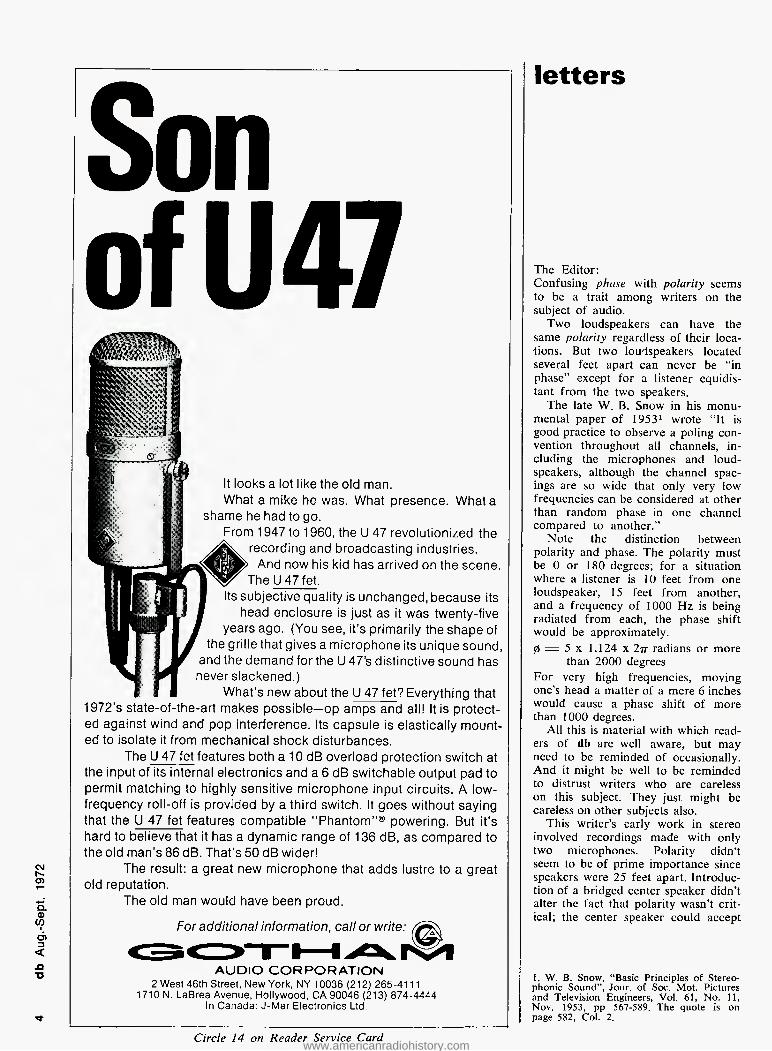
Son
ofU47
It looks a lot like the old man. What a mike he was. What presence. What a
shame he had to go. From 1947 to 1960, the U 47 revolutionized the
recording and broadcasting industries. And now his kid has arrived on the scene.
The LMTfet. Its subjective quality is unchanged, because its
head enclosure is just as it was twenty-five years ago. (You see, it's primarily the shape of
the grille that gives a microphone its unique sound, and the demand for the U 47's distinctive sound has never slackened.)
What's new about the U 47 fet? Everything that 1972's state-of-the-art makes possible—op amps and all! It is protect- ed against wind and pop interference. Its capsule is elastically mount- ed to isolate it from mechanical shock disturbances.
The U 47 fet features both a 10 dB overload protection switch at the input of its internal electronics and a 6 dB switchable output pad to permit matching to highly sensitive microphone input circuits. A low- frequency roll-off is provided by a third switch. It goes without saying that the U 47 fet features compatible "Phantom"® powering. But it's hard to believe that it has a dynamic range of 136 dB, as compared to the old man's 86 dB. That's 50 dB wider!
The result; a great new microphone that adds lustre to a great old reputation.
The old man would have been proud.
For additional information, call or write:
AUDIO CORPORATION 2 West 46th Street, New York, NY 10036 (212) 265-4111
1710 N. LaBrea Avenue, Hollywood, CA 90046 (213) 874-4444 In Canada: J-Mar Electronics Ltd.
Circle 14 on Reader Service Card
letters
The Editor: Confusing phase with polarity seems to be a trait among writers on the subject of audio.
Two loudspeakers can have the same polarity regardless of their loca- tions. But two loudspeakers located several feet apart can never be "in phase" except for a listener equidis- tant from the two speakers.
The late W. B. Snow in his monu- mental paper of 19531 wrote "It is good practice to observe a poling con- vention throughout all channels, in- cluding the microphones and loud- speakers, although the channel spac- ings are so wide that only very low frequencies can be considered at other than random phase in one channel compared to another."
Note the distinction between polarity and phase. The polarity must be 0 or 180 degrees; for a situation where a listener is 10 feet from one loudspeaker, 15 feet from another, and a frequency of 1000 Hz is being radiated from each, the phase shift would be approximately. 0 = 5 x 1.124 x 277 radians or more
than 2000 degrees For very high frequencies, moving one's head a matter of a mere 6 inches would cause a phase shift of more than 1000 degrees.
All this is material with which read- ers of db are well aware, but may need to be reminded of occasionally. And it might be well to be reminded to distrust writers who are careless on this subject. They just might be careless on other subjects also.
This writer's early work in stereo involved recordings made with only two microphones. Polarity didn't seem to be of prime importance since speakers were 25 feet apart. Introduc- tion of a bridged center speaker didn't alter the fact that polarity wasn't crit- ical; the center speaker could accept
1. W. B. Snow, "Basic Principles of Stereo- phonic Sound", Jour, of Soc. Mot. Pictures and Television Engineers, Vol. 61, No. 11, Nov. 1953, pp 567-589. The quote is on page 582, Col. 2.
www.americanradiohistory.com

Uhoosing professional audio controls involves com- plex compromises between noise, life, accuracy, and price. No one design can achieve all the alternatives. To satisfy all requirements, a full range of attenuator models is required, and that's what Waters offers: a complete line of attenuators, all of which feature MystR® — a proprietary conductive plastic resistance element.
MystR's glass-hard, smooth wiping surface achieves noise levels below 20/tiV (at least 100db down) over a trouble-free life of at least ten million operations.
Zero to truly "stepless" attenuation is achieved with Waters' computer-controlled curve- shaping technique which actually tailors the attenua- tor resistance element as- suring superior tracking ac- curacy.
If you'd like to call our hand, send for Waters' Audio At- tenuator brochure which describes their complete line of linear and rotary attenuators and pan pots. Use the coupon provided, or better yet, phone 617- 358-2777 for immediate service.
Name- Position- Company Phone Street City State Zip_
Boston Post Road Wayland, Ma, 01778
I'd like further information on Waters attenuators and MystR* conductive plastic elements. □ Send me your attenuator brochure and "The
MystR Story" □ I need additional information:
a CT > C <p 'l Cf) CD ■a
CD -si K>
Circle 32 on Reader Service Card www.americanradiohistory.com

mmmmm iwo
,(L^
iPc
■fti >uca~
~f'}CuJii>^^C
ac^
Automated Processes, Inc. 80 Marcus Dr. Melville, New York 11746
Dear Mr. Processes,
A funny thfng happened to us "e^n3n, S?, ^""eLaJch ^"''SrL^lrelterr^^ce SJar,alls into the "MAJOR BREAKTHROUGH"
category. HE HAVE MADE AUTOMATED MIXDOWN REALLY POSSIBLE.
You know ho. eyonybody wants to ».ke lut"", o^
SSSHHSSr'mfiR »ssw~
ratio.
2. It features a 90dB range of highly accurate, infinite resolution control.
3 Fast update speed of 800 microseconds per fun<;ti9n can scan
128 functions at the rate of 10 tTmes per second).
4. Its failsafe system renders immunity to dropouts, solices or level changes .
5. Simple and trouble free circuitry requiring no alignment tone or tricky adjustments.
that we think your company ts s«eU automation together . ((WALL.Srt J
De "Car Alison. ^ "
,Grea t: y ~~ -J
Let's get Utr m*nory n "oc ^1' ^
''"'"■"y. °"'ts ears?'4' ,s ,
^ for
HMi
CljLbi*L*n*S)
XoxoXoxoK
Circle 13 on Reader Service Card www.americanradiohistory.com
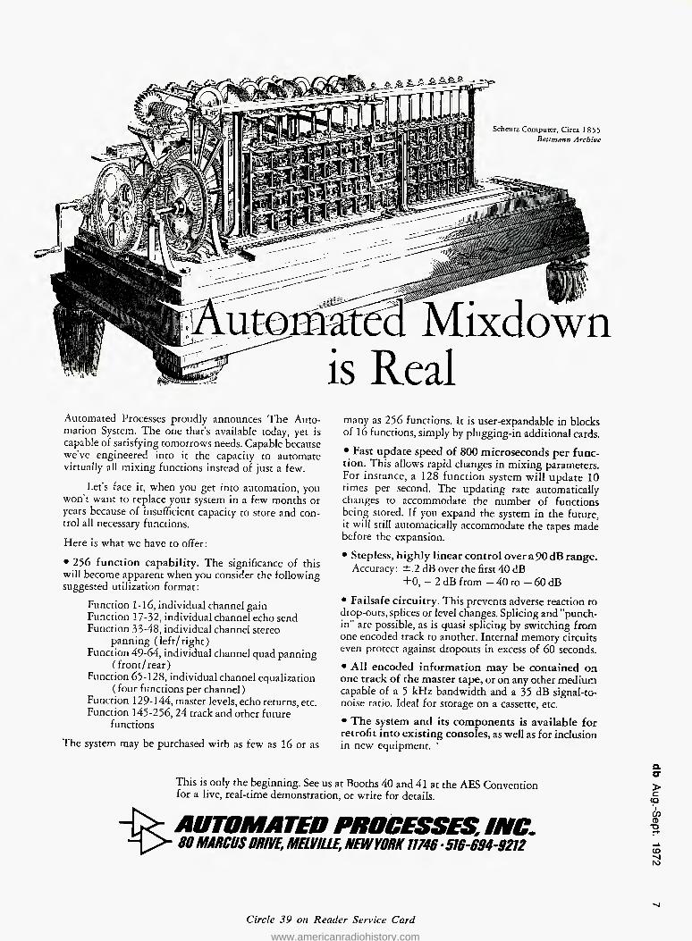
Scheutz Computer, Circa 1855 Bettmann Archive
Mixdown
is Real
Automated Processes proudly announces The Auto- mation System. The one that's available today, yet is capable of satisfying tomorrows needs. Capable because we've engineered into it the capacity to automate virtually all mixing functions instead of just a few.
Let's face it, when you get into automation, you won't want to replace your system in a few months or years because of insufficient capacity to store and con- trol all necessary functions.
Here is what we have to offer:
• 256 function capability. The significance of this will become apparent when you consider the following suggested utilization format:
Function 1-16, individual channel gain Function 17-32, individual channel echo send Function 33-48, individual channel stereo
panning (left/right) Function 49-64, individual channel quad panning
(front/rear) Function 65-128, individual channel equalization
( four functions per channel) Function 129-144, master levels, echo returns, etc. Function 145-256, 24 track and other future
functions
The system may be purchased with as few as 16 or as
many as 256 functions. It is user-expandable in blocks of 16 functions, simply by plugging-in additional cards.
• Fast update speed of 800 microseconds per func- tion. This allows rapid changes in mixing parameters. For instance, a 128 function system will update 10 times per second. The updating rate automatically changes to accommodate the number of functions being stored. If you expand the system in the future, it will still automatically accommodate the tapes made before the expansion.
• Stepless, highly linear control over a 90 dB range. Accuracy: ±2 dB over the first 40 dB
+0, — 2 dB from — 40 to — 60 dB
• Failsafe circuitry. This prevents adverse reaction to drop-outs, splices or level changes. Splicing and "punch- in " are possible, as is quasi splicing by switching from one encoded track to another. Internal memory circuits even protect against dropouts in excess of 60 seconds.
• All encoded information may be contained on one track of the master tape, or on any other medium capable of a 5 kHz bandwidth and a 35 dB signal-to- noise ratio. Ideal for storage on a cassette, etc.
• The system and its components is available for retrofit into existing consoles, as well as for inclusion in new equipment. '
%
This is only the beginning. See us at Booths 40 and 41 at the AES Convention for a live, real-time demonstration, or write for details.
AUTOMATED PRO 80 MARCUS DRIVE, MELVULC. HEW YORK 1U1B ■516-694-9212
a o* > c (p *1 en CD "a
CO -vl ro
Circle 39 on Reader Service Card
www.americanradiohistory.com

1176 VX limiting amplifier
Cool-aid
for hot
seuncfs
Cool and reliable, the 1176 Is the Industry's most popular limlter for controlling today's hot sounds. It has ultrafast attack time independent of peak duration or frequency, adjustable from front panel. Release time is also adjustable from front panel. Push button selection of four compression ratios, of 20:1, 12:1, 8:1, or 4:1. It is a compact 19" rack mount size — 31/2 " high.
Available from better professional audio dealers every- where or send for complete technical details today!
11922 Valerio Street. No. Hollywood, California 91605 (213) 764-1500 Exclusive export agent: Gotham Export Corporation, New York
L i R or L - R about equally well. But when a third microphone was used to focus central stage events, thereby adding a strong monophonic component to each stereo channel, polarity of the center speaker had to be L 4" R. If the L R polarity was used, the soloist almost disappeared; whatever central stage events were to bo heard had to be combined in one's hearing system out of what came from the flanking speakers. And it should be remembered that the sounds reaching one's ear from the flanking speakers are in random phase for all but the lowest frequencies. This means that one can not ignore polar- ity; Snow's remark still holds; one should maintain proper polarity, even if it is impossible to achieve "correct phase."
But remember L + R or L — R is not phase but polarity; one can achieve one or the other with a polarity reversal of one or the other channel. Phase is a general concept that includes all phase angles from 0 to 360 degrees and multiples thereof. Polarity has to do with the special case where precisely 180 degrees is introduced.
Pan! W. Klipsch Klipsch and Associates Hope. Arkansas
db binders only $4.95 postpaid
Heavy-weight binders are now available to hold the thirteen issues of Volumes I and 2. Rich brown leather-grained virgin vinyl, with our name printed in black on the spine and front cover, is electroni- cally sealed over rigid board to give your volumes of db lasting protec- tion Keep your copies preserved in perfect condition, protected from dust and damage.
| Please send me copies of ! ; the db Magazine binder. My 1
| check for $ is enclosed < 1 (sorry, no c.o.d ). j j Name ■ i Address . J number and streel ^ I 1 | city stale zip i i (New York Stale residents 1 1 please add 6% sales tax). I I i \ Mail to: db the Sound Engineer- i i ing Magazine, 980 Old Country t 1 Road, Plainview, N Y. 11803. 1 I I
Circle 24 on Reader Service Card www.americanradiohistory.com
total taps duplicating
with "BUILBINB BLOCK" simplicity
CASSETTE TO CASSETTE, REEL TD CASSETTE, REEL TO REEL
a o- > c (Q CO CD "D
CD "v| N)
TELEX COMMUNICATIONS DIVISION | 9600 ALDRICH AVE. SO. • MINNEAPOLIS, MINN. 55420 g DBS " PLEASE SEND INFORMATION ON DUPLICATOR. "
NAME
TITLE
INSTITUTION
ADDRESS
CITY STATE
PRODUCTS OF SOUND RESE
HICLIjIEX COMMUNICATIONS DIVISION
9600 ALDRICH AVENUE SOUTH • MINNEAPOLIS, MllVNESOTA i CANADA DOUBLE DIAMOND ELECTRONICS. LTD , 34 Progress Avenue, Scarboroi
EXPORT: ROYAL SOUND COMPANY, INC . 409 North Mam Street, Freeport, N gh 4. Ontario Y 11520
Circle 29 on Reader Service Card
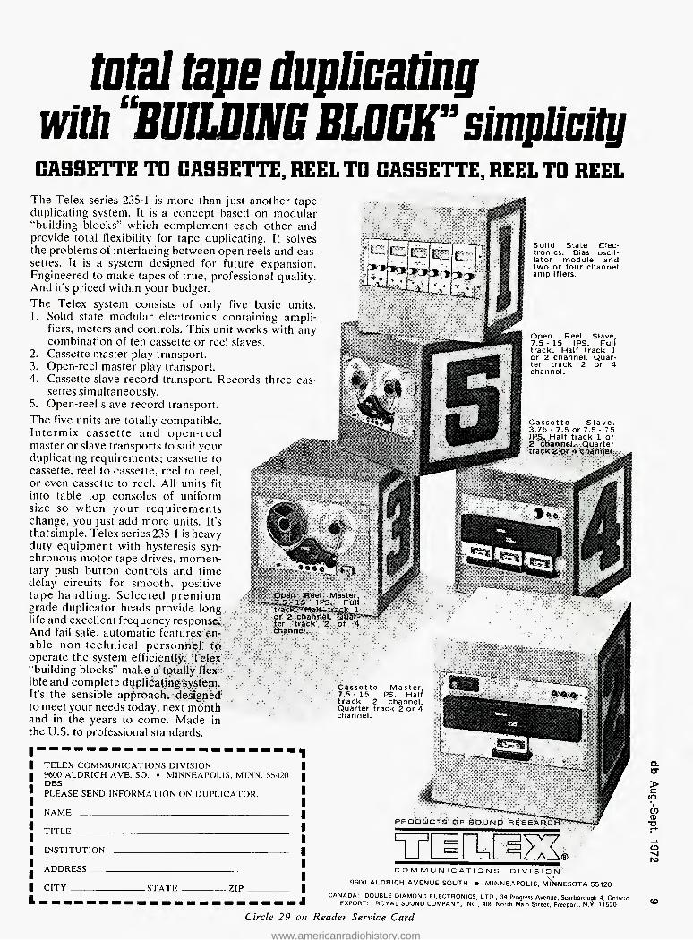
The Telex series 235-1 is more than just another tape duplicating system. It is a concept based on modular "building blocks'" which complement each other and provide total flexibility for tape duplicating. It solves the problems of interfacing between open reels and cas- settes. it is a system designed for future expansion. Engineered to make tapes of true, professional quality. And it's priced within your budget. The Telex system consists of only five basic units. 1. Solid state modular electronics containing ampli-
fiers, meters and controls. This unit works with any combination of ten cassette or reel slaves.
2. Cassette master play transport. 3. Open-reel master play transport. 4. Cassette slave record transport. Records three cas-
settes simultaneously. 5. Open-reel slave record transport. The five units are totally compatible. Intermix cassette and open-reel master or slave transports to suit your duplicating requirements; cassette to cassette, reel to cassette, reel to reel, or even cassette to reel. All units fit into table top consoles of uniform size so when your requirements change, you just add more units. It's thatsimple. Telex series235-1 is heavy duty equipment with hysteresis syn- chronous motor tape drives, momen- tary push button controls and time delay circuits for smooth, positive tape handling. Selected premium grade duplicator heads provide long life and excellent frequency response. And fail safe, automatic features en- channel, able non-technical personnel to operate the system efficiently. Telex 'building blocks" make a totally flex- ible and complete duplicating system. It's the sensible approach, designed to meet your needs today, next month and in the years to come. Made in the U.S. to professional standards.
Cassette Master, 7.5-15 IPS. Half track 2 channel. Quarter track 2 or 4 channel.
Open Reel Slave, 7.5 - 15 IPS. Full track. Half track 1 or 2 channel. Quar- ter track 2 or 4 channel.
Cassette Slave. 3.75 - 7.5 or 7.5-15 IPS. Half track 1 or 2 channel. Quarter
Solid State Elec- tronics. Bias oscil- lator module and two or four channel amplifiers.
www.americanradiohistory.com

WOR-FM, the country's leading FM/Stereo rock station, has been using Stanton cartridges since its inception.
Program Director Sebastian Stone likes the smooth, clean sound the Stanton delivers; the way it is able to pick up everything on the record so that the station can assure high quality transmission of every recording.
Eric Small, Chief Engineer for WOR-FM, likes the way that Stanton cartridges stand up under the wear and tear of continuous use. "We standardized on Stanton a couple of years back," Small said, "and we haven't had a cartridge failure since." Studio Supervisor Artie Altro concurs.
Whether you're a professional or simply a sincere music lover, the integrity of a Stanton 681 Series cartridge delivers the quality of performance you want.
It affords excellent frequency response, channel separation, compliance and low mass and tracking pressure. And every Stanton cartridge is fitted with the exclusive "longhair" brush to keep grooves clean and protect the stylus.
For complete information and specifications on Stanton cartridges, write Stanton Magnetics, Inc., Terminal Drive, Plainview, L.I., N.Y. 11803.
'A
sraNTOn
All Stanton cartridges are designed for use with all two and four-channel matrix
derived compatible systems.
George Alexandrovich
THE AUDIO ENGINEER'S
HANDBOOK
• In our every day work we are used to dealing with audio lines of short length which don't introduce any noticeable ill effects to our signals. Inductance of the wire is low. So is the capacitance to ground and be- tween conductors. D.c. resistance is usually on the order of few ohms and is generally disregarded.
However, in radio and television work audio crews are faced with a problem of transmission over tele- phone lines—which may be providing an audio path from the local sports arena or from a political convention hall all the way across the country. The telephone company sees to it that signals traveling a long distance are boosted from time to time to compensate for the losses occuring along the way. So-called repealers provide needed amplification. But broadcasting audio signals have to be of wider frequency range than those just for speech. In a long line, high frequencies are attenuated because of capacity between wires and ground. Low frequencies are lost because of series inductance of the wire. Mid- range frequencies are affected by re- sistive losses as well as inductive and capacitive effects to a lesser degree. Response of a typical telephone line has a 6 dB slope with the knee at approximately 2-3 kHz, attenuating 10 kHz more than 10 dB. The low end has similar rolloff characteristics which will vary from line to line—- but not so much that we can not help correct it to some degree.
As I said before the telephone company sees to that that deteriora- tion of the signal quality doesn't reach the point where it can not be boosted or restored without too much noise. The telephone company is also will- ing to lease equalized lines to broad- casters—and even make up the equal- ization losses. Depending on the amount of equalization required, losses may run as high as 30 dB. However, equalized lines are generally available as unidirectional wires per-
Figure 1. The simplest telephone equalizer.
PHONE LINE TO CONSOLE
mitting communications in one direc- tion only. But to obtain an equalized line may present some difficulties these days with telephone crews very busy with maintenance work. If you need a good line in a hurry you may as well forget it. The only thing left for you to do is to help yourself. Have an equalizer handy so that it can be inserted into the line any time you need it.
The simplest equalizer for the line consists of rlc resonant circuit ad- justed to the frequencies of about 8-9 kHz and connected across the line as shown in Figure 1, The resistive part of the circuit adjusts the effect of the circuit on the response of the line. If the r is minimal, the effect is great- est but also the loss introduced by the equalizer is the greatest. If r is made large effect is small. Typical values for the circuit are; 1 200 mH with q of 50 or more c 2000 pF r 0-1000 ohms
Because the gain of the line" changes with the increased effect of the high- frequency equalizer, it may be advis- able to use a double ganged poten- tiometer so that the second section adjusts the output level as the amount of equalization is varied. See Figure 2. Resister R3 has to be adjusted so that gain in the midrange remains constant as the potentiometer is ro- tated. What this circuit does is simply keep the losses constant. It should be kept in mind that output level from such an equalizer should be fed into the medium level input in the con- sole where additional amplification is available. Normal telephone levels range between —20 to —10 dBm level. If we introduce a loss of an- other 10-15 dB because of equalization equalizer output level will be more like —30 or —35 dBm. If you are concerned with a permanent line there is no need for adjustable equal- ization.
But now let us assume that you require to boost low frequencies as
Figure 2. It may be advisable to use a double-ganged pot.
OUT
Circle 50 on Reader Service Card www.americanradiohistory.com

/* i * £ i i U i
""IT 'Til "" |
i u'\ "'1 \ ""'1' " ''i^1 v ' '
1 j».\ \
8-IN, 4-OUT: $1890.
Plus Tax. o • rJ "
Here's what $1,890 buys you:
One each floor-standing TASCAM Model 10 Mixing Console. Manufactured by TEAC Audio Systems.
Eight input modules, each providing a 3-position input pad, feedback-type mic atten- uator, line attenuator, 3-position input selector, hi- and lo-pass filters, hi, lo and mid-band equalizers, com- plete echo-send and receive cir- cuitry including pre- and post-selec- tion, channel and pan assignment pushbuttons, a pan pot, and a unique straight-line fader.
Four sub-master modules, each pro- viding a straight-line fader, source/ tape monitor control, and separate monitor level controls.
One master module with a straight- line fader. Four 4" VU meters with fast-acting LED peak indicators.
Plus, pre-wired facilities for up to four additional input modules and other optional accessories includ- ing talkback, remote transport con- trol, quad panner, and headphone monitor.
And if all that seems like an awfully good buy for your money, here's what $1,770 for our Series 70 Recorder/Reproducer buys you;
1/2" transport, 4-channel modular electronics, with overdub, plug-in head nest with fer- rite heads and scrape filter, remote control connector, touch-button solenoid/relay controls with anti- spill circuitry, heavy-duty 6-pole torque motors, and indirect drive 2- speed hysteresis-synchronous cap- stan motor.
Both units available with studio line impedances optionally.
Since you're still impressed by these values, don't forget the sales tax. That's the one accessory that's not optional.
See us at the AES Convention, New York
CORPORATION
Q. a- > c cp 'l O) CD "D
CD K)
TEAC AUDIO SYSTEMS CORPORATION OF AMERICA 5440 McConnell Avenue Los Angeles, California 90066
(213) 390-3566
Circle 21 on Reader Service Card
www.americanradiohistory.com

FREE
from
AKG
48-page technical brochure on Field Effect Transistor condenser microphones and describing in detail; A. Structural details of new type
miniature condenser microphone capsules with various pick-up pattern, complete with perform- ance and comparison charts.
B. F.E.T. condenser microphone preamplifier technology, includ- ing schematics and specifica- tions.
C. Modern powering techniques of F.E.T. condenser microphones.
D. Application hints, including illus- trations and descriptions of re- co'ding accessories.
AUDIO CONSOLE
Figure 3. Tap the phone line as shown to feed the phone line into the audio system.
This booklet is of interest to every innovative recording and broadcast engineer. Please fill out coupon be- low or send us your request on your organization's stationery.
NAME
TITLE
FIRM
ADDRESS
CITY
Circle 16 on Reader Service Card
well. Simply erect the same type of a circuit as for high frequencies ex- cept with different values. If you want the circuit to resonate at 100 Hz you would need either a 2 henry choke and 1 mF capacitor, or a I henry in- ductor with 2 /iF capacitor—or any other suitable Ic combination produc- ing desired low-frequency resonance (consult a reactance-frequency chart). Connected across the line in a similar way, it will attenuate all frequencies outside the resonant frequency. Again, resistor in series will limit the effect of the circuit.
Needless to say, a conventional telephone line has d.c. potentional and has to be decoupled by a capaci- tor—and then a fixed resistor has to be connected across the line to act as a holding circuit for the relay at the telephone exchange. This refers only to the two-way telephone line with dial and ring capabilities. Let us as- sume that you use a conventional telephone receiver for the incoming line. As the outside call is received, contact is initially established by lift- ing the head set. In order to feed the signal into your audio system you have to tap the phone line as shown on Figure 3. The disconnect switch is for the purpose of breaking the circuit after the transmission is com- pleted. After the initial contact is established through the use of tele- phone set this switch is turned on and the receiver is put back on the hook. Then the holding circuit takes over the function of keeping the line open.
ft is quite obvious that very few people in this field of audio have time to build and experiment with their own circuits. Simplest thing is to use available program equalizers for the job. Inserting an already designed unit into the telephone line may prove to be the simplest thing.
Now let us examine the problem of line equalization from the radio station to the transmitter site. Al- though many stations depend on the telephone company, just as many string their own lines—at times for several miles. These stations should consider themselves lucky. They can
pump as much level into the lines as they want to—knowing that signal will not be clipped, as in the case when commercial telephone lines are used. Those stations can and should expect better signal-to-noise ratio at their transmitters, as well as better frequency response.
The transmission line for the signal can be fed from a source impedance of almost zero ohms without a trans- former, with ample voltage to insert the equalizer on the other end—and still have enough level to drive a transmitter. Only the telephone com- pany requires a 600-ohm pad on the output of the console. Impedance of the line as measured at the transmit- ter will consist of impedance of the wires only, therefore losses will be minimal. If the impedance measured is only a couple of hundred of ohms at midrange, load doesn't have to match it—let it be bridging (and bal- anced, of course).
fn this case of a super private line you can pre-emphasize the signal be- fore feeding it into the line—just as it is done in tape recorders or disc recording. Boost the most trouble- some frequencies (highs and lows) and then de-emphasize them at the other end if required. This may also hold true for leased lines if there is no appreciable restriction on the level feeding the line. Usually there are transformers in the line which re- strict you from feeding high enough levels, also the telephone company is concerned about the crosstalk be- tween adjacent channels or lines, ff the signal strength in one pair of wires is much higher than certain acceptable level it could be heard in other lines.
As long as transmission of signals will be done through wires, problems of losses and equalization will be with us. New techniques of signal trans- mission are emerging, starting with scrambling using digital and analog signal conversion which tend to im- prove the existing conditions. But even with these techniques response of the line is very important because it limits the transmission rate and its quality. ■ Circle 36 on Reader Service Card >"
STATE ZIP
pa Fa ic
MICROPHONES' HEADPHONES DISTRIBUTED BV NORTH AMERICAN PHILIPS CORPORATION lOO EAST 42r.<i STREET. MEW YORK. NEW YORK 10017
PHONE LINE
Nl FREQ
held u
E0ndenser
^fis^ophon,
www.americanradiohistory.com

We left the power to the people
The new Sony STC-7000 combines a super 1.7uV tuner and a preamp with the widest possible flexibility. There's no power amplifier section—leaving the choice of power output completely up to you. You can make it a receiver with the thundering power of today's mightiest amplifiers, or make it a moder- ate-power receiver whose other speci- fications are anything but moderate.
All the convenience and compactness of ordinary receivers are still yours, with your power amplifier neatly tucked out of sight. But the performance is any- thing but ordinary. Consider the impres- sive tuner specifications: 1.7uVIHF sen- sitivity, 100 dB selectivity, and a signal- to-noise ratio of 70 dB. And to make
the most of that performance, the tuner facilities include switchable high-blend and muting, signal-input and center- channel tuning meters, a long, linear- spaced dial, rear-panel oscilloscope output jacks to help you aim your an- tenna for minimum multipath. There's also a coaxial connector for a 75-ohm shielded antenna lead.
The preamplifier is equal to the finest separate components. High voltage in- tegrated circuits and other advanced features give it sensitivity, overload resistance, wide dynamic range, and clean, quiet performance to match the high standards of the tuner: only 0.1% harmonic or 1M distortion, with 10Hz to 100 kHz response, and a 90 dB signal-
to-noise ratio. And its facilities are as complete as those on any separate preamplifier, including such unusual extras as rear-panel audio scope output jacks, dual tape monitors with direct tape-to-tape dubbing, front and rear panel Aux inputs, a microphone mixing input with shutoff, and sharp-cutting 12 dB/octave high and low filters.
Think of it as the finest, most powerful receiver you can buy — or the finest, least powerful. The choice is yours. The cost of this high quality component, $549.50* Sony Corporation of America, 47-47 Van Dam Street, Long Island City, New York 11101.*Suggested retail price.
SONY Preamp Tuner
www.americanradiohistory.com
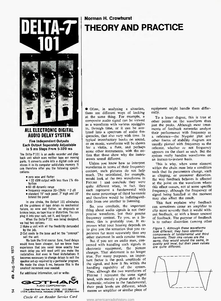
ALL ELECTRONIC DIGITAL AUDIO DELAY SYSTEM Five Independent Outputs
Each Output Separately Adjustable in 5 ms Steps From 5-320 ms
The Delta-TlOl is an audio recorder and play- back unit which uses neither tape nor moving parts. It converts audio into a digital code and stores it in its computer solid-state memory. It can therefore offer you the following specifi- cations:
• zero wow and flutter • +22 dBM output with less than 1% dis-
tortion • 60 dB dynamic range • frequency response 20—12kHz ±2 dB • standard 19" rack panel, 7" high and 18"
behind the panel In one stroke, the Delta-T 101 eliminates
all the problems of tape delay: no mechanical failure, no wow and flutter, no drop-outs or broken loops, no tape hiss or distortion. You can plug it into your rack, set it, and forget it.
When the Delta-T 101 was being designed, we had two options: 1) Make a unit with all the flexibility demanded
by the job; 2) Cut costs to the bone and let the "concept"
sell the unit. We took the first course. Sure, fixed delays
would have been cheaper, but we know from experience that you never know exactly how much delay you will need until you make the installation. And even in fixed installations it becomes necessary to change delays to suit the speaker set-up required by a particular program. We made the steps 5 ms, because this is the smallest increment ever needed. For additional information, call or write:
AUDIO CORPORATION 2 West 46th Street, New York, NY 10036 {212)26M111 1710 N. La Brea Avenue. Hollywood, CA 90046 (213)874-4444
Circle 41 on Reader Service Card
Norman H. Crowhurst
THEORY AND PRACTICE
• Often, in analyzing a situation, there are different ways of looking at the same thing. For example, a composite audio signal can be viewed as a waveform with various squiggles in, through time, or it can be ana- lyzed into a spectrum of audio fre- quencies, that also vary with time. In typical introductory books on sound, or on music, waveforms will be shown for a violin, a flute, and perhaps some other instruments, with the no- tion that these show why the instru- ments sound different.
Unless you know how to interpret waveforms in terms of their frequency content, such pictures do not help much. The uninitiated, for example, would look at the two waveforms in Figure 1 and conclude they were quite different when, in fact, they each represent a fundamental with the same percentage of third harmonic and therefore would be indistinguish- able from one another in listening.
So, you conclude, the important thing about audio signals is not their precise waveform, but their precise frequency content. To you, as a lis- tener, this is probably true. It ex- presses what your hearing depends on to give you the sensation that you ex- perience far more accurately than any other statement in such concise terms.
But if you are an audio man, con- cerned with handling such signals in electronic equipment, the picture changes. That statement is no longer true. For many purposes, an impor- tant factor is the peak amplitude of the signal, and how it fits within the handling capability of the system. Thus, although the two waveforms of Figure 1 represent the same signal level, with merely a phase shift in the harmonic, relative to the fundamental, their peak levels are different, which means an amplifier or similar piece of
equipment might handle them differ- ently.
To a lesser degree, this is true at other points on the waveform than just the peaks. Although most treat- ments of feedback networks analyze their performance with frequency as a reference—-the Nyquist plot and other forms of stability diagram are usually plotted with frequency as the referent, whether or not frequency appears on the chart as such. But the system really handles waveforms on an instant-to-instant basis.
This is why, when some element within the chain runs into a condition such that its parameters change, such as clipping, or crossover distortion, the way feedback behaves is affected at the point on the waveform where this effect occurs, not at some specific frequency, although the frequency of signal being handled at the moment may also affect the result.
This fact explains why feedback can sometimes cause an amplifier to clip more severely than it would with- out feedback, or with a lesser amount of feedback. The purpose of feedback is to reduce distortion (among other
Figure 1. Although these waveforms look different, they have identical components of fundamental and third harmonic. Their rms values are the same, they would sound the same, in quality and level, but their peak values are quite different.
www.americanradiohistory.com

PROFESSIONAL
STUDIO
EQUIPMENT
3 speeds - 15, IVi & 33/4ips: hysteresis syn- chronous drive motor
torque reel motors "capable of providing the most faithful re- production of sound through the magnetic recording medium . . . to date" -Audio mag- azine, 4/68
optional Trac-Sync
Specs 15ips 7'Aips w. & fl. 0,06% 0.09% f. resp. +2dB
40Hz to 30kHz
20H2 to 20kHz
S/N -60dB -60dB
computer logic con- trols for safe, rapid tape handling and editing; full remote control optional
individual channel equalizers
third head monitor with A/B switch; meter monitoring of source, tape, output and source+tape; sound - with - sound, sound-on-sound and echo
2 mixing inputs per channel
individual channel bias adjust
"construction . . rugged enough to withstand parachute drops" -Audio mag- azine, 4/68
RECORDERS &
REPRODUCERS
$1790 for basic rack- mount half-track stereo deck, about $2300 with typical accessories; Formica floor console $295, rugged portable case -$69
SX711 Claimed by its pro audio owners to be the finest professional tape recorder value on the market today - price versus performance • Frequency response at T'/pips ±2dB 20Hz-20kHz, at SWips ±2dB 20Hz 10kHz ■ Wow & flutter at 7%ips0.09%, at 3%ips 0.18% ■ S/N at y/jips-GOdB, at 33/iiips -55dB ■ Facilities; bias metering and adjustment, third head monitor with A/B switch, sound with-sound, two mic or line inputs, meter monitoring same as CX822, 600n output ■ Remote start/stop optional, automatic stop in play mode ■ $895 for full track mono deck as shown, $995 for half track stereo deck
SP722 Ideal reproducer for automation systems ■ Meets or exceeds all NAB standards ■ Remote start/stop optional, automatic stop in play mode ■ $595 for half-track stereo reproducer
STUDIO MONITOR
AMPLIFIERS
Crown tape recorders and reproducers are available in 42 models with almost any head configuration, including 4 chan- nels in-line. Patented electro magnetic brakes maintain ultra-light tape tension and never need adjusting. They are made by American craftsmen to professional quality standards, with industrial-grade construction for years of heavy use.
All Crown amplifiers are warranteed three years for parts and labor. They are 100% American-made to profes- sional quality standards. All are fully protected against shorts, mismatch and open circuits. Construction is indus- trial-grade for years of continuous operation. For more information, write CROWN, Box 1000, Elkhart, Indiana 46514
DC 300
D60 D150 Delivers 30 watts RMS per channel at 8Q "Takes only l3/t" rack space, weighs 8V2 lbs. ■ IM distortion less than 0.05% from 1/lOw to 30w at 8Q ■ S/N 106dB below 30w output ■ $229 rack mount
Delivers 75 watts RMS per channel at 8Q ■ IM distortion less than 0.05% from O.Olw to 75w at 8ft ■ S/N HOdB below 75w output ■ Takes rack space, weighs 20 lbs. ■ $429 rack mount
Delivers 150 watts RMS per channel at 8ft ■ IM distortion less than 0.05% from 0.01 w-150w at 8ft ■ S/N HOdB below 150w output at 8ft ■ Lab Standard per- formance and reliability ■ "As close to absolute perfection as any amplifier •ve have ever seen" - Audio magazine, 10/69 ■ $685 rack mount
Circle 40 on Reader Service Card
www.americanradiohistory.com

for that heavy studio sound!
Ul-3%
leveling
amplifier
The great one with the Electro-Optical attenuator ■ Half rack size ■ High output (+25 dBm) ■ Low price (under $400.00)
See your dealer or write for complete specifications.
Circle 27 on Reader Service Card
purposes). So if an amplifier com- ponent clips quite positively and nothing will make it deliver more current, voltage, or whatever, feed- back will correct the input to try to eliminate the deficiency.
Then it's like the irresistable force (produced by the feedback), meeting the immovable object (the component that clips): catastrophe! The impact is worse than if the clipping was less severe, or the feedback less forceful. This is something that the theory, based on frequency analysis, does not show. Waveform is modified on an instant-to-instant basis.
Here's another example. Suppose that a clipping effect acts as short- circuit to signal, beyond a certain level, and that it is sensitive not to absolute level from a reference zero (Figurf. 2) but to changing signal. Then when signal exceeds a certain level in one direction, the output waveform will suddenly square off be- yond that point.
If the squaring off referred to ab- solute signal, the flattening would cease only when the level of input came back down to the same point. But if the circuit responds to chang- ing signal, as soon as the signal change reverses direction, the flatten- ing ceases, which means it hits the opposite clipping point a little sooner.
presents the new RP10-12 1 PROFESSIONAL EQUALIZER for RECORDING and PLAYBACK
^fERFECT tailoring of octave-wide bands... Infinitely variable adjustment flexibility ... Special Effects programming ... Instant re-setting
,i__ via Computone-Charts
Recording Studios ' Audiophiles • Night Clubs • Performers • Theatres Churches • Gyms • Auditoriums • Hi-Speed Duplicating' Musical Groups
SPECIFICA TIONS SPECIAL FEA TURES
2V output. Typ; 95 dB up to 100K o
o'SKT' ■ OUTPUT ADJUST" contr
VU METER: Precision ± .5% mel visual display, to enable exact un INDUCTORS." Toroidal and Shield CIRCUIT BOARDS: Military grade RESISTORS: Low noise selected c SWITCH CONTACTS: Gold plated DEFEAT SWITCH: Electrically rerr
input output rr hroughout
, s the Equalizer from ti OUTPUT ADJUST: Controls a continuously variable 18 dB r, from - 12 dB to + 6 dB. to match output to input. RANGE: 12 dB boost and 12 dB cut, each octave centered a 60. 120, 240, 480. 960, 1920. 3840. 7680 and 15,360 Hz SIZE: Walnut-grained wood case 5'/. " * 18' x 1! , Rack pan. STEREO 20-12 $299.50
i: 1310 E Wakeham Ana, Cal 92705 Ph. 714 836-8375
1972 MASTER OUTPUT LEVEL: "Frequency spectrum levl" controll to right channels, continuously variable 18 db range, for unity gain HARMONIC DISTORTION: Less than .1% THD @ 2 v.. Typ: .05% IM DISTORTION- Less than 1% @ 2 v.. Typ: 05% ® 1 v. SIGNAL-TO-NOISE RATIO: Better than 90 dB below 2V output. INPUT IMPEDANCE: Operable from any source I00K ohms or lesi (any Hi-Fi Pre-amp, Receiver or Tape Record OUTPUT IMPEDANCE: Operable into 3K ohms or greater - (any Hi-Fi Amp, Receiver or Tape Recorde SIZE: Walnut-gramed wood cise S'/i ' x 18 x 11". or rack.mount ALSO AVAILABLE, t
SAME AS 20-12 ABOVE, EXCEPT HAS 600 OHM OUTPUT 20-12-600..$349.50
Figure 2. Some waveforms to show different possible effects of clipping, at the same nominal level (a slight difference in clipping level is shown, only to avoid confusion between the two shapes).
Figure 2 shows this distinction. Another example of a signal that
can be viewed differently is a fre- quency modulated radio-frequency carrier. From the viewpoint of the modulating signal—the audio—the central carrier frequency is modified by the modulation, without changing its amplitude. This is a fairly simple concept, and one that proves useful in examining modulator and demodu- lator circuit behavior. You consider the amplitude and frequency of a waveform that, at every point, looks like a single, pure sinusoid.
Provided the frequency, during its fluctuation, does not deviate by more than the prescribed 75 kHz from cen- ter frequency, this will, in general, ensure that the transmitted intelli- gence stays within the band allowed to that carrier. But that is not quite enough, from the viewpoint of deter- mining whether any energy splashes into an adjoining channel,
A radio frequency, frequency mod- ulated by a specific modulating fre- quency, can also be regarded as gen- erating a whole family of sidebands, distributed across the spectrum like lines separated by intervals equal to the modulating frequency.
The magnitude and distribution of these side bands, for any one modu- lating frequency, depends on the ex- act relationship between the modulat- ing frequency and the so-called devi- ation ratio. And when, as happens on practical signal, many modulating fre- quencies are applied simultaneously, the changing assortment of sidebands generated becomes very complex, al- though the composite wave, at all times, looks like a single, simple sine wave, whose frequency is varying.
If a few tiny stray sidebands spill over into an adjoining channel, and are then trimmed off by a filter that removes everything above 75 kHz deviation from central carrier, how does this affect the modulation trans-
UNDISTORTED WAVEFORM
WAVEFORM CLIPPED WITHOUT OPERATING SHIFT
WAVEFORM WHERE DIPPING PRODUCES OPERATING SHIFT
Circle 25 on Reader Service Card www.americanradiohistory.com
WE HAVE IT,
IT WORKS,
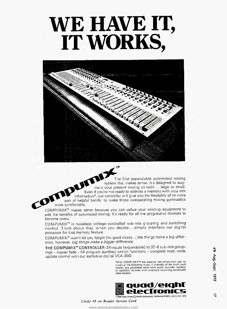
The first expandable automated mixing system that makes sense. It's designed to aug-
ment your present mixing console . .. large or small. Even if you're not ready to address a memory with your mix
information*, our controller will give you the flexibility of an extra pair of helpful hands: to make those exasperating mixing gymnastics
more comfortable. COM PL) MIX'" makes sense because you can utilize your existing equipment to add the benefits of automated mixing. It's ready for all the progressive thinkers to become doers. COMPUMIX™ is noiseless voltage-controlled sub-mix grouping and switching control. Think about that, when you decide... simply interface our digital processor for that memory feature. COMPUMIX"" won't let you forget the good mixes. Little things make a big differ- ence, however, big things make a bigger difference.
THE COMPUMIX™ CONTROLLER-24 inputs (expandable) to 32-6 sub-mix group- a
ings • master fade • 54 program auxiliary switch functions • complete read, write, or update control with our exclusive digital VCA-800. >
(O *With COMPUMIX™ the memory mix-information can be *, stored in the following ways: 2 channels of the multi-track CO master, any peripheral multi-track audio recorder, cassette or cartridge recorder with minimum recording bandwidth requirements.
.i*
Quad/eiqtir
11929 Vose Street □ North Hollywood, California 91605 □ 213/764-1516 Circle 45 on Reader Service Card
CD "O
CD ^4 N>
www.americanradiohistory.com

mitted? Removal of those sidebands, without changing anything within the allowed band, would probably cause the modulated carrier either to vary slightly in amplitude, or else to fail to follow the input modulation faithfully, or perhaps both.
But when feedback is applied over
the whole system, so that, with all sidebands beyond 75 kHz of central carrier completely removed, the de- modulated signal modifies the input, the remaining sidebands, within the allowed range, are modified so that very little fluctuation in amplitude occurs, and the output modulation closely follows the input.
With amplitude modulation, all those frequencies arc present. True the signal can also be regarded as a carrier whose amplitude is modu- lated without its frequency being changed. But those sideband frequen- cies are inseparably linked with the modulation frequencies they repre- sent. If the sidebands are lopped off at 4.5 kHz on either side of the car- rier, the transmitted modulation is lopped off at 4.5 kHz, period.
With frequency modulation, the link is not so definite. In both cases, what influences the received signal is how the effective carrier varies, one in amplitude and the other in frequency, with the opposite quantity regarded as constant in each case. But in frequency modulation, whether frequencies more than 75 kHz from the carrier are rep- resented in the composite synthesis does not directly affect the modula- tion. as it does in amplitude modula- tion.
Of course, that statement has limits too. If it didn't, fm would find a use
on medium frequency band, where it is definitely not applicable: you can- not have a fractional deviation ratio, If the modulating frequency is 9 kHz. the nearest sidebands it can generate, am or fm. will be 9 kHz on either side of the carrier.
Maybe the notion I receive in some readers" letters, that you can have your cake and eat it too. derives from listening to too many campaigning pol- iticians. who make all kinds of prom- ises. As adults, we should not be so naive, although I am not exempt from such foolishness.
Earlier this year. I had heard sev- eral complaints about the Truth in Lending procedures, from both borrow- ers and lenders in various categories. So I studied the matter. Foolishly, I presumed that Congress had designed this legislation for the mutual benefit or protection of both borrowers and lenders and, because a Senator from our state is on the Bank and Finance Committee, 1 wrote to him about it.
Using my mathematical ability, I had worked out a more satisfactory procedure, that would involve less work and achieve what I thought the object was, which I sent to him in a 3-page letter. Can you guess what happened? He passed my letter to the real architects of the bill, who replied to me.
Congress (Senate or Representative House) did not design that bill. The Federal Reserve Board did. And from their reply—also a 3-page letter—that my Senator forwarded to me. the rea- sons they give for rejecting my sug- gestions make it very plain that the object of the legislation was not what I had foolishly imagined. Rather it is to help every American to get himself further into debt, thereby giving more control to various levels of creditors and most control to the super-creditors of all: the Federal Reserve System.
Why do I mention this? Because it is an election year. Maybe the fact that the people we elect get their directives, not from us, but from vari- ous government agencies, will explain why there is so little choice between Democratic. Republican, or Independ- ent. They all follow bureaucrats' or- ders. And in a sense, it's our fault. We do not give them anything else to do.
If we would just stop listening to campaign promises that they have not a prayer of fulfilling, and look for candidates who want to represent us and implement what we want done thereby reversing roles back to what the Constitution laid down, instead have the servants boss the masters, this country could change in a hurry. Why not pass the word? ■
AUDIO ENGINEER
Electronics engineer with expe- rience in circuit design of com- plete high-performance audio systems. Must have a good working knowledge of low-noise amplifiers, active and passive filters, power amplifiers and power supplies. Some acoustic experience, perhaps in sound reinforcement or consumer hi-fi will be helpful.
Must have a demonstrated rec- ord of accomplishment includ- ing one or more products of his design in successful production.
Send resume and earnings rec- ord in complete confidence to:
H. E. Boyce ELECTRO-VOICE, INC.
600 Cecil Street Buchanan, Michigan 49107
The
Parametric
Equalizer
Of the many Equalizers available today, the ITI ME-230 Parametric Equalizer is the only one that offers you all these truly outstanding recording features— • AH controls are continuously variable.
No more working with arbitrarily fixed positions. With the ITI Parametric Equalizer—you record using your mind and ears, with your hands only trans- mitting the orders of what you hear.
• Remarkable frequency range. 10-800 Hz, 100-8,000 Hz, and 400-25,600 Hz, each accurately calibrated, with boost or cut up to 12db about any center frequency.
• Continuously variable Selectivity or "Q". From 4 to 14dB/octave with no effect on the absolute magnitude of the center frequency.
• No inductors used—In the Parametric sections. Ringing on transients is vir- tually non-existent.
The ME-230 Parametric Equalizer—our Super Equalizer—is for all those who want more than "just good enough" sound recording. We invite you to call or write for more details about its high de- gree of flexibility and superb perform- ance.
[m INTERNATIONAL TELECOMM, INC.
McCormick Road and Schilling Circle Hunt Valley, Maryland 21031 Telephone: 301/666-7770
Circle 17 on Reader Service Card www.americanradiohistory.com

The magnificent feven
We've been hearing unsolicited rave reviews from soundmen across the country concerning our seven ingeniously versatile problem-solving audio control components (1) M68 Microphone Mixer, vanguard of the low-cost, high-performance portable mixers; (2) M68-RM Mixer, with built-in reverb for vocalists and special effects; (3) M67 Mixer, the trail-blazing low-cost professional mixer; (4) M63 Audio Control Center, that gives you variable response shaping; (5) M62V Level-Loc, the audio level controller thai auto- matically limits output level; (6) M688 Stereo Mixer, made to order for stereo recording and audio-visual work; and finally, (7) M675 Broadcast Production Master, that teams up with our IV167 to give a complete broadcast production console (with cuing) for under $325. Write for the new Shure Circuitry catalog that shows them all:
Shure Brothers Inc. 222 Hartrey Ave., Evanston, III. 60204 KM
Circle 30 on Reader Service Card
a. a- > c (p CO CD TD
www.americanradiohistory.com

John M. Woram
THE SYNC TRACK
Systems Reliability
• As this is being written, I have just returned from the sixth annual Audio/ Recording Seminar at Brigham Young University where I had been invited to conduct the session on Control Room Engineering.
At a later date, db will have a de- tailed description of the seminar. In
this month's column. I'd like to dwell on at least one subject that came up during the seminar; equipment: or to put it more broadly, systems reliabil- ity. The subject came up almost as an afterthought towards the end of the class, and so we didn't have too much time to get deeply involved in
the pros and cons. Unfortunately reliability often comes up only as an afterthought, as Ralph Nader has been noting for so long.
Anyway, a day after the seminar ended, I was flying back to Fun City, thinking of all sorts of brilliant things to say, now that it was too late. Perhaps it was the altitude—at 30,000 feet, systems reliability is a very important subject. But even on the ground, a little more thought wouldn't hurt.
Which brings us back to the studio. (Well, what did you expect?) I sup- pose it an oversimplification to say that recording gear should have built-in reliability, hut reliability costs money, and may not show up on the spec sheets in measurable terms. In fact, reliability judgments can only be made after the passage of time. If the equipment doesn't blow out (or up) we can eventually say it's reliable. Of course, with the obvious exception of new products, most equipment has been on the mar- ket long enough for some general consensus of reliability to have been formed.
you write it
Many readers do not realize that they can also be writers for db. We are al- ways seeking good, meaningful articles of any length. The subject matter can cover almost anything of interest and value to audio professionals.
Are you doing something original or unusual in your work? Your fellow audio pros might want to know about it. (It's easy to tell your story in db.)
You don't have to be an experi- enced writer to be published. But you do need the ability to express your idea fully, with adequate detail and information. Our editors will polish the story for you. We suggest you first submit an outline so that we can work with you in the development of the article.
You also don't have to be an artist, we'll re-do all drawings. This means we do need sufficient detail in your rough drawing or schematic so that our artists will understand what you want.
It can be prestigious to be published and it can be profitable too. All arti- cles accepted for publication are pur- chased. You won't retire on our scale, but it can make a nice extra sum for that special occasion.
Pha/e Linear ZOO
The critic/lay it on...
"The world's best amplifier!" W. R. Hickman, High Fidelity Editor Seattle Post-intelligencer
. . in a class by itself" Julian Hirsch, Stereo Review
"... a product for the all-out audiophile interested only in superlatives!. . . performance is the most impressive we have tested."
Norman Isenburg, High Fidelity
"Based on its sound quality only — regardless of price or power output — the 700 is in our opinion an excellent buy, and probably also a must with the majority of acoustic suspension loudspeakers and the new "hybrid" electrostatic reproducers so popular these days. At about $1.00 per watt. . . the Phase Linear 700 amplifier is probably the best bargain on the market today."
Editor, Hi Fi Newsletter
"An incredible instrument, really too good for home high fidelity use."
Collyn Rivers, Editor Electronics Today
. . distortion . .. was as low as we can go with the present equipment! There's no need to present a frequency response curve . .. since it is perfectly flat... to beyond the limits of our generator! Hum and noise figures were below anything we have encountered before. Breakup, as when an opera singer hits her high C, need never happen again, for now there is the Phase Linear amplifier and when that enormous reserve of power is needed, the 700 is capable of handling practically anything you care to feed it."
C. G. McProud, Audio
"WE WONDER IF 700 WATTS IS ENOUGH!"
Julian Hirsch, Stereo Review
CORPORATION 405 Howell Way, Edmonds, Wa. 98020
Circle 34 on Reader Service Card www.americanradiohistory.com

INTRODUCING THE
FINEST PERFORMER
ON rm STAGE,
THE TURNER TC10.
We've got it! A great new multi-port cardioid dynamic microphone. The TC10. It's the best you can buy, and we can prove it. In a series of carefully controlled tests, we ran the TC10 mike-to-mike against the top professional entertainment microphones in the indus- try. We got what we wanted—documented evidence that TC10 specifications meet or exceed those of any equivalent model. Results of these tests are available from Turner or the representative nearest you. See them and you'll agree. It's time for a change. It's time to try this remarkable new Turner microphone.
You'll get a multi-port cardioid dynamic with each component individually selected. Featuring: —26 db front-to-back discrimination on an axis of 180°, a frequency range of 50-15,000 Hz with an extremely flat response. —55 db output level. 150 ohm impe- dance. A unique acoustic cartridge mount which vir- tually eliminates shock and handling noise. Each TC10 is numbered, registered and packed in a hand- some metal carrying case with its own individual re- sponse curve. Find out more about the TC10 and the rest of the high-quality TC series. Write for details. Turner Division. Conrac Corporation. 909 Seventeenth Street N.E., Cedar Rapids, Iowa 52402.
DIVISION OF CONRAC CORPORATION
a o-
> c cp CO CD "O
CD -nI ro
Circle 37 on Reader Service Card www.americanradiohistory.com
For example, some time ago we solved one of our little reliability problems with monitor amplifiers. We had a quantity of very inexpen- sive amps with very impressive specs. And, in practice, the amps fully met their published ratings. Just one little problem though—they had an un- comfortable way of dying when one least expected it. Also, lifting an in- put or output was a virtual guarantee that they'd go up in smoke.
So. we installed a bunch of Crown DC-300 power amps. End of prob- lem. The darn things are indestruct- able, and Lord knows we've tried hard to do them in. They also cost about three times as much as the old unreliables. But, it doesn't take too long to realize there's no savings in buying unreliable amps. Trouble- shooting any system, you proceed by eliminating—one by one—the prob- able failure points. The fewer there are. the quicker and easier the trouble shooting.
A month or two ago, I mentioned how sealed relays had cut down our failure rate. On a larger scale, the DC-300 amps have reduced our monitoring problems to zero. That's worth a lot of money. In fact, it seems we can easily afford the Crowns. It's the others that we can't afford.
Another frequent reliability prob- lem is headphones. In any studio.
phones are bound to get a lot of abuse. There's just no way to prevent them from getting dropped, kicked, or just plain stepped on.
Sometime ago. I talked to the Koss people about the need for a "studio proof" headphone. They were inter- ested in working on this problem, and we began by buying a small quantity of their red-devil phones (model KRD-71I), Then every time we man- aged to break one, we'd send it back for analysis. In a very short time, they came up with the phones we now use —a modified version of the 711. The phone uses a steel-cased Switchcraft plug, and an extra-durable coil cord with improved strain relief where the cord enters the ear piece. We've been using them now for over six months and have had no failures. No doubt they will last a lot longer, but from past experience I know that six months of studio use is a long time.
Studios interested in trying these modifiied phones should contact Joe Kotowski at the Koss factory in Milwaukee, Wisconsin for price and delivery information.
While on the subject of head- phones, it seems that every studio has its own method of supplying a head- phone feed to the musicians. Our sys- tem is not ultra-sophisticated by any means, but it works well and is reli- able.
Stereo phones generally use three
conductors, common, left, and right. Since we supply a mono feed to our two cue lines, we use the left and right conductors only. The ground is unused, and so, its only function is to connect the left and right ear- pieces together—in series—thereby doubling the total impedance of the phone. Since the Koss phones men- tioned above have an impedance of about 250 ohms for each earpiece, this makes the impedance 500 ohms per phone. Even with twenty phones connected in parallel, the total im- pedance is a safe 25 ohms. Note that the phones themselves do not require rewiring. The only modification re- quired is at the amplifier. Simply connect the left and right conductors to the amps' two output terminals and you're in business.
As a safety measure, we've inserted a 10-ohm power resistor in one of the conductors, so that momentary shorts—as phones are plugged in and out—do not affect the amp. We use a stereo amp. the Crown D-40. with each side of the amp driving its own phone feed. The sight of a Crown amplifier driving a headphone system raises an occasional eyebrow on visit- ing engineers; but again, the old re- liability factor must be considered. The combination of the Koss phones and the Crown amp has reduced our cue line problems to zero. What's that worth?
Let's get back to the subject of re- lays for a minute or two. Sealed units are more reliable than the non-sealed variety. Enough said. But, what about the reliability of the circuit in which the relay functions? It's a common practice to connect one side of a relay to the power supply, with the other side connected—via a length of wire —to a switch. Closing the switch grounds the length of wire and actu- ates the relay. The logic (?) of this convention is that if the length of wire is accidentally grounded any- where along its length—for example, a short circuit—the power supply will not be damaged. The only thing that will happen is that the relay will be- come activated. This assumes that the power supply is more valuable than whatever it is that the relay is doing.
But, is it? What if the relay is in the record circuit, and the accidental short has just erased the string track which was recorded a few weeks ago? If I had a choice. I'd prefer a situa- tion where a failure would put a ma- chine out of the record mode, rather than into it.
To me, a system that may destroy something more valuable instead of itself is not reliable. What does your tape machine do? ■
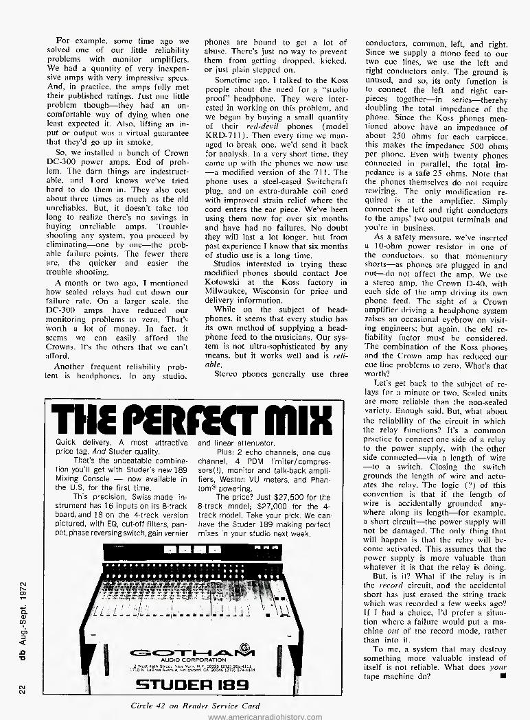
THC PQtfCCT fflIX Quick delivery. A most attractive price tag. And Studer quality.
That's the unbeatable combina- tion you'll get with Studer's new 189 Mixing Console — now available in the U.S. for the first time.
This precision, Swiss-made in- strument has 16 inputs on its 8-track board, and 18 on the 4-track version pictured, with EQ, cut-off filters, pan- pot,phase reversing switch, gain vernier
and linear attenuator. Plus: 2 echo channels, one cue
channel, 4 PDM limiter/compres- sorsd), monitor and talk-back ampli- fiers, Weston VU meters, and Phan- tom'" powering.
The price? Just $27,500 for the 8-track model; $27,000 for the 4- track model. Take your pick. We can have the Studer 189 making perfect mixes in your studio next week.
Circle 42 on Reader Service Card www.americanradiohistory.com

Relax,Engineers.The ES6000 will make
you look good.
It will take very little
of your time.
But it won't eliminate
We introduced the
Electro Sound 6000 32:1 tape duplicating system a year ago and have waited until
we had enough field reports to verify this claim:
The ES6000 system at 32:1 is the same reliable workhorse that our 4000 system at 16:1 has been throughout the world since 1966.
The 6000 is neither temperamental nor delicate, and doesn't need the kind of coddling and tender loving care that engineers must lavish on some other systems to keep them operating properly. It just keeps rolling out first-rate tapes shift-atter-shift, day-after-day, leaving the engineer with more time for his other duties.
We don't really put you people out of work, though. There are still plenty of top flight (and smiling] engineers at CBS and EMI. where some of our first OOOO's went. But the 6000 is working just as well for smaller independents like Southeastern Records in Hialeah, Florida, and Teal in Johannesburg, South Africa.
In addition to its hardy reliability, here are some of the other attractive features the ES6000 offers you.
32:1 speed Cue tone Injector system Constant tape tension Modular plug-In record and reproduce ampli fiers Crystal control bias generator with 2MHz frequency Plug-in replaceable ferrite heads for easy convertibility from
8-track to cassette duplication Continuous loop assembly with loop bin capacity of more than
2,000 feet [more than enough for a C-90 cassette] Compatible ferrite heads available for "Quad eight" and
standard eight duplication Dolby noise reduction system can be used with the E36000
We also have those terrific Electro Sound winders and splicers.
□ □□□
» •
aopp
AUDIOMATIC CORPORATION 237 West 54th Street, New York, N.Y. 10019
(212) 582-4870 Cable: AUDIOMATIC Telex No. 12-6419
Worldwide distributors of Electro Sound tape duplicating equipment and accessories
Circle 46 on Reader Service Card www.americanradiohistory.com

A POWERFUL B4IR
EXPOSED BY MCI!
CM 1^- CD
Q. CD op d) 13 <
"D
C\J
llffntri> ! / //7
These permit adjustment of cue mix levels and echo mix levels.
ECHO RETURN TO TRACKS/ Provides level control on 20db boost amplifier 16 track selects, solo, and cue feeds for one echo return.
PLEATED AND ROLLED 6" ARMREST
TALKBACK MIKE METERS LIGHT Activates if track meters 9-16 are being used to monitor, tracks 17-24. (See tracks meter select.)
TRACK METERS Tracks 17-24 share meters with 9-16 (See tracks^eter select) CONNECTOR BLOCKS On rear covered by metal back panel provides hjdden connections for all inputs and outputs
SUBMASTER TRACK GAIN Provides track attenuation during recording when many inputs are mixed together and mix must be held while the group is attenuated.
SOLO LIGHT Activates if any solo buttons are pushed.
4 ECHO RETURNS TO QUAD MIX Each channel has 20db boost, level control and pan controls identical to an input strip. They feed directly into the quad mix busses and each also has a solo button.
SUBMASTER CUE AND ECHO
Permits each input to be fed into any of the 16 summing^, busses which then feed the first 16 tracks. The direct button on each strip feeds the module input directly to its track output.
CUE AND ECHO LEVELS These 4 busses are identical and may be used inter- changeably. (See also master echo and cue levels.)
ECHO SWITCH This button connects echo to the output of the equalizer (thus only the single input can be used.) Instead of the monitor booster, (any signals entering the track are used.)
Defeats board status command and places module in mike status. A red light indicates use of this button (See status switches.) SOLO SWITCH Routes its track signal to the control room mon without disturbing program circuits. It can be used during recording.
The monitor fader controls the percent of track output sent to quad busses. In remix status the fader controls tape return level. The pan control provides L-R panning hrough a front -back mute switch.
H. F. EQUALIZATION is through a 2 frequency-'select push button and II position ± 12db shelf with center off.
MID RANGE EQUALIZATION is through a 12 . frequency select switch and an 8 position / -+- 14db shelf with an off position. /
LOW FREQUENCY EQUALIZATION is through a/ 2 frequency select push button and an / 11 position • 12db shelf with center off. /
Provides 24-50db mike gain through an'extremely I noise amplifier with balanced transformer input.
ILLUMINATED CONDUCTIVE PLASTIC FADER
TRACK SELECT
0 DUB SWITCH
MONITOR AND PAN CONTROLS
EQUALIZER
MIKE TRIM
Is in front of the equalizer circuit and will accept its Input either from the mike preamp or tape. (See status buttons)
osc. SELECT Permits oscillator feed from patch bay to t'he 16 track busses or the quad mix busses
SLATE SELECT Permits slating signal to be fed to 16 track busses, or quad mix busses.
MIKE LEVEL CONTROLS For talkback, slating, and communicate.
\ TB MIKE BUTTONS Conveniently located near arm rest and just off center of console. The TALKBACK BUTTON feeds slating and the studio monitor while muting the control room to prevent feedbacl the COMMUNICATE BUTTON feeds only the cue busses. It can be used during recording.
Circle 26 on Reader Service Card www.americanradiohistory.com

When you buy MCl's new JH-416 mixing console—priced at a phe- nomenal $19,500 for the 16-track model — you'll have enough money left over to buy our JH-16 recorder ($16,500) . .. and still be paying less than what you'd ex- pect for a comparable mixing console alone. Expandable to 24 tracks (total: $25,100), the Jl-1-416 makes possible a complete studio package of heavy hardware at
unheard-of savings. And to save even more consider starting out with an 8-track version of the JH-416 ($13,900), which you can build on later.
We'll match our console—its spe- cifications and functions — with any competitive model, even the $40,000-and-up jobs. Recorder and mixer — together, a powerful pair from MCI.
\WC.\ \ \
4007 N.E. 6th Avenue Ft. Lauderdale, Florida 33308
QUAD METERS Continuously monitor the quad mix busses. 2 TRACK METERS (See meter selector) POWER SENSE LIGHTS Sense any bipolar voltage imbalance or failure and gives warning to operator. MONITOR SELECT The studio and control monitor have independent selectors, both given the choices of: Mono Tape; 2 TK Tape; Aux 1,2; Cue 1,2; Echo 1.2; 2 Track Mix; Quad Mix; and Quad Tape Return. The control room monitor has quad output. The studio ■^monitor comes with 2 TK output. A quad studio monitor is also available. The studio also has automatic muting when 2 TK or Quad Mix is monitored while the console is in mike mode. 2 TK METER SELECT Feeds the left and right channel meters. The selection
: Mono Tape; 2 TK Tape; Aux 1, 2; Cue 1, 2; Echo 1, 2; 2 TK Mix; Quad Tape Front; and Quad Tape Rear. 240 JACK PATCH BAY
m Provides interface for inputs, outputs, and inner electronics. MONITOR MODE SELECT
£|l ^ These determine whether the monitor acts as mono. 2 channel or quad output In addition, the control room monitor also has a 1-2 speaker switch used in mono mode. STATUS BUTTONS Three buttons which feed transistor drivers providing
"non-transient operation of status and mix relays in each module thus programming the console in 3 conditions.
(The following gives electrical flow through 1 input module.)
MIKE STATUS - Mike signal routed through preamp, patch bay, conductive fader, equalizer booster, solo and assignment buttons, submaster level control, track summing amplifiers to the patch bay and out to tapes and also to the monitor level quad mix and echo, cue busses.
TAPE STATUS - identical to the first except tape return signal is routed to the monitor level by a status relay. This allows a multi track master to be played through the same mix circuits used to monitor track feeds during recording.
REMIX STATUS - routes the tape return from patch bay through the main fader, equalizer, quad pan, and
yCue, echo feeds. (Also see o-dub button) TRACKS METER SELECT Switches track meters 9-16 to tracks 17-24.
MONITOR LEVEL CONTROLS The CONTROL ROOM MONITOR comes with a 4 channel rotary fader. The STUDIO MONITOR comes with a rotary 2 channel or 4 channel fader.
^REMOVABLE PANEL Acts as writing surface but can be removed and replaced by optional metal insert for your custom electronics.
nquadmaster fader Fades quad mix, stereo mix and mono mix.
LOG RESET BUTTON Sets beginning of tape location at position of tape when pushed.
AUT0-L0C BUTTON Activates auto-locate function.
REMOTE CONTROL This unit is furnished with the recorder. It houses 16 sets of illuminated mode switches — ready, overdub, & safe. The remote also houses a complete set of deck motion controls. The entire remote-auto-locator package is less than 8"H X 12"W X 5"D Sophisticated logic activates automatic individual/master input monitor switching.
THREE TAPE HEADS Are quickly removable for easy 8-16 conversion. All connectors are on top of the deck. AUTOMATIC SHIELDS & TAPE LIFTERS Can also be manually controlled.
CONSTANT TAPE TENSION Electronic control maintains constant tension at all reel loading situations
MCI AUTO LOCATOR An optional accessory which can be connected to any JH-16 in the field. The auto locator permits automatic return to any two starting points. A 99 minute, 59 second clock is also contained in the auto locator.
DISPLAY BUTTONS LOG - Brings Log count into auto locator counter after using "O" or clock functions. "0" — Resets auto locator counter to current tape position while not affecting log count. CLOCK BUTTONS ON - Turns on clock and switches digital display from auto-loc to clock. RUN — Starts and stops clock.
RECORD AND INPUT LIGHTS Over each track meter.
16 VU METERS Furnished on all machines. All mainframes are fully wired and tested regardless of head configuration. CONTROL CARDS House adjustments for reprodu:e, overdub, and record lave Is.
NOISE GATE An optional accessory which plugs onto Control Cards. The noise gate reduces channel noise to >80 DB when program mater a I is not present.
FOLD-OUT ELECTRONICS RACK Permits easy access to all wiring and rear of card connectors. ALL METAL CABINET Finished with mar-resistant poly urethane paint and woodgrain vinyl, The front, top, and back open for servicing. CASTERS Designed for use on thick carpeting of recording studio floors
BIAS AMPLIFIER CARDS House the adjustments for erase, bias and bias calibrate.
VU METER SWITCH Switches VU meter to read bias level.
REPRODUCE AMPLIFIER CARDS House a plug in equalizer with adjustments for fast & slow speed, high & low frequency equalization. RECORD AMPLIFIER CARDS House a plug-in equalizer with adjustments for fast & slow high frequency equalization and record calibration.
Q. o- > c cp 'l cn CD "O
CO N)
ro cn
www.americanradiohistory.com

Martin Dickstein
SOUND WITH IMAGES
Think quiet
• Speaking of ecology, and who isn't these days, a recent public exhibit gave visitors brief lessons in sound, provided interesting facts and ideas for better mental and physical health, visually demonstrated and offered helpful advice on the subject of what to do about a most serious form of pollution—noise.
Noise itself is not of recent origin, of course, nor is it strictly American. In fact, according to information available at this display, Julius Caesar was so bothered by noise that he outlawed chariot driving at night; Charles De Gaulle banned by law transistor radios in public places; the hearing ability of some of the young rock musicians of today has deterior-
ated to the level of that of a 75-year old man; and a tribe in the quiet re- gions of the Sudan has been found which has 75-year old men with hear- ing capability of a 25-year-old Amer- ican man.
The temporary exhibit, "Think Quiet: The Sound Show," was set up by the Owens-Corning Fiberglas Corp. at their New York headquar- ters for the purpose of presenting to the public the benefits of sound and the detriment of noise. To do this, live demonstrations, visual exhibits and "hands-on" displays provided to give the visitors an understanding of some of the principles of sound, the meaning and dynamics of noise, and some possible means of controlling
\u\e\ \ \ in the great northeast!
CNJ h- O)
CL 0) 00 d) 3 < XJ T3
CO CNJ
audiotechniques, inc.
121 hamilton avenue
Stamford, conn.
• sales • service
• installation • leasing
"Just 45 minutes from Broadway" ... is audiotechniques, Inc., your headquarters in the Northeast for MCI and all your pro audio requirements. From Virginia to Maine, we service what we sell!
See us at the Fall A.E.S. (Booths 44, 45, 54, 55)
\U\V1\ \ \
audiotechniques, inc. 121 hamilton ave. Stamford, conn. 06902 (203) 359-2312
Figure 1. The benefits of sound and the detriments of noise are illustrated. The demonstrator uses a variety of noisemaking devices including the giant mosquito, a sound cannon, and a household motor.
this rapidly growing menace. First, people were invited to take
a hearing test. Different tones at vari- ous levels of loudness were repro- duced from tapes played on three LaBelle Repeater units. A brief ex- planation of how the ear works was given, and a short description of what sound is and how it is measured was also presented, with the introduction of the term dB. A booklet gave a short discussion on sound terminology and the characteristics of loudness. It was also shown that high-pitched sounds were far more noticeable than low-pitched ones at the same decibel level giving rise to a relative weight difference described by the term dbA.
A film was then shown at the next display which gave the viewer a three-minute wrap-up of a 24-hour period recorded and filmed on the comer outside the building in which the exhibit was taking place. The in- tersection is an extremely busy one and is intensely noisy during the nor- mal work day, but the sound level drops dramatically during the night, although never quite down to the level of quiet. The display then discusses the physiological and psychological dan- gers inherent in this type of disturb- ance. Aside from hearing loss, the body reacts to noise in other ways. A sound of even moderate level and short duration can cause the brain's blood vessels to dilate while the exact opposite is true in other parts of the body. Blood pressure rises, heart rhythm changes, pupils of the eyes dilate and even the stomach changes its rate of acid secretion. Excessive noise has been related to stress-caused ailments such as heart disease, ulcers and indigestion. Steady noise has been found to bring on tension, nervous- ness and irritability which in turn may cause fatigue, depression and inefficiency.
Circle 18 on Reader Service Card
www.americanradiohistory.com

The AR Laboratory Standard Transducer
A speaker for professional use
from Acoustic Research
ACCURACY AND FLEXIBILITY: The AR-LST offers a total of six different energy profiles — all accurately known and repeatable at the turn of a switch, which is located on the front of the cabinet. This permits a degree of control and precision that is usually found only in electronic equipment.
FLAT ENERGY CAPABILITY: The AR-LST is capable of a flat energy output characteristic that, in our judgement, establishes a new state of the art. The graph shown above represents the acoustic power output produced by the AR-LST with its control set to the "flat" position. The horizontal line below 500 Hz indicates the relative woofer level.
LOW DISTORTION: As with the AR-3a, harmonic distortion measurements down to the lowest audible frequencies are, to the best of our knowledge, the lowest of any loudspeaker system available.
WIDE DISPERSION: AR's hemispherical dome tweeters produce exceptionally smooth, wide dispersion of midrange and high frequencies, even in rooms or studios that are acoustically rather dead.
POWER HANDLING: Multiple drivers for midrange and high frequencies enable the AR-LST to handle power levels significantly higher than AR's finest speakers designed primarily for home use.
Detailed information on the AR-LST is available on request. Mail the coupon below.
Acoustic Research, Inc. 24 Thorndike Street Cambridge, Massachusetts 02141, Dept.
Please send the booklet describing the AR-LST to
NAME
ADDRESS
Circle 31 on Reader Service Curd
www.americanradiohistory.com
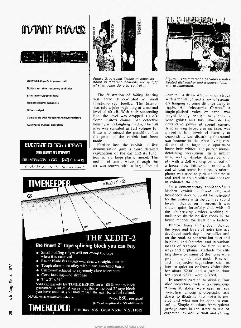
Over 1200 degrees of phase shift
Built-in variable frequency oscillator
Internal envelope follower
Remote control capability
Stereo output
Compatible with Moog and Arp synthesizers
Automatic-manual operation
EUEDTIDE CLDCh UORHiS
SB5 LUEST 54 STREET
nEwvoBhcnv mq [as] aa-qiaa
Circle 38 on Reader Service Card
=jl 1
-■m i i s i (pri a r= |
r^nj
Figure 2. A guest listens to noise as heard in diflerent locations and is told what is being done to control it.
The frustration of failing hearing was aptly demonstrated in small telephone-type booths. The listener was told a joke beginning at a normal level of 60 dB. With each succeeding line, the level was dropped 10 dB. Some visitors found that defective hearing is no laughing matter. The full joke was repeated at full volume for those who missed the punchline, hut the point of the exhibit had been made.
Farther into the exhibit, a live demonstration gave a more detailed explanation of the car and its func- tion with a large plastic model. The motion of sound waves through the air was shown with a large "sound
c\j r^- cn
Q. <D CO I d) ZD < X3 T3
co C\J
Figure 3. The dillerence between a noise treated dishwasher and a conventional one is illustrated.
cannon," a drum which, when struck with a mallet, caused a row of stream- ers hanging at some distance away to ripple. An "electronic Caruso," a single-pitched voice on tape, was played loudly enough to shatter a wine goblet and thus illustrate the destructive power of sound energy. A screaming baby, also on tape, was played at four levels of intensity to demonstrate how disturbing this sound can become in the close living con- ditions of a large city apartment house built without the proper sound- deadening precautions. In a similar vein, another display illustrated sim- ply with a doll walking on a roof of a house, how this would sound with and without sound isolation. A micro- phone was used to pick up the noise and feed to an amplifier and speaker to enhance the effect.
In a contemporary appliance-filled kitchen exhibit, different electrical household devices could be activated by the visitors with the relative sound levels indicated on a screen. It was shown quite forcefully that with all the labor-saving devices working si- multaneously the noisiest room in the house reaches the level of a factory.
Photos, tapes and slides indicated the types and levels of noise that are developed each day in the office and on the road, at construction sites and in plants and factories, and in various means of transportation such as sub- ways and airplanes. Methods for cut- ting down on some of the noise were given and demonstrated. Practical and inexpensive suggestions such as how to quiet an ordinary dishwasher for about $2.00 and a garage door for about $5.00 were offered.
In another part of the display, four slide projectors, each with drums con- taining 80 slides, were used in rear projection among photographs and charts to illustrate how noise is cre- ated and what can be done to con- trol it. Simple solutions from quieter garbage cans in the street to use of carpeting, as well as wall and ceiling
www.americanradiohistory.com
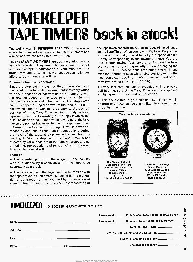
TIMEKEEPER
TAPE TIMERS back in steak!
The well-known TIMEKEEPER TAPE TIMERS are now available for Immediate delivery. Our latest shipment has arrived and we are ready to fill your order.
TIMEKEEPER TAPE TIMERS are easily mounted on any V4-inch recorder. They are fully guaranteed to meet with your complete satisfaction or your money will be promptly refunded. At these low prices you can no longer afford to be without a tape timer.
Difference from the Stop-Watch Since the stop-watch measures time independently of the travel of the tape, its measurement inevitably varies with the elongation or contraction of the tape and with the rotating speed of the tape recorder, subject to change by voltage and other factors. The stop-watch can be stopped during the travel of the tape, but it can- not rewind together with the tape back to the desired position. With the Tape Timer moving in unity with the tape recorder, fast forwarding of the tape involves the quick advance of the pointer, while rewinding of the tape moves the pointer backward by the corresponding time.
Correct time keeping of the Tape Timer is never de- ranged by continuous repetition of such actions during the travel of the tape, as stop, rewinding and fast for- warding. Unlike the stop-watch, the Tape Timer is not affected by various factors of the tape recorder, and so the editing, reproduction and revision of your recorded tape can be done at will.
Features • The recorded portion of the magnetic tape can be read at a glance by a scale division of 1/4 second as accurately as a clock.
• The performance of the Tape Timer synchronized with the tape prevents such errors as caused by the elonga- tion or contraction of the tape, and by the variation of speed in the rotation of the machine. Fast forwarding of
the tape involves the proportional increase of the advance on theTapeTimer.When you rewind the tape, the pointer will be automatically moved back by the space of time exactly corresponding to the rewound length. You are free to stop, rewind, fast forward, or forward the tape even continuously and repeatedly without deranging the timing on the machine, thus prohibiting errors. These excellent characteristics will enable you to simplify the most complex procedure of editing, revising and other- wise processing your tape recording.
• Every fast rotating part is provided with a precise ball bearing, so that the Tape Timer can be employed at high speed with no need of lubrication.
• This trouble-free, high precision Tape Timer, within an error of 2/1000, can be simply fitted to any recording or editing machine.
Two models are available:
The Standard Model is calibrated for 7.5 and 3.75 ips and can also be
used at 15 ips. Dimensions are
1%" x 3Vi". It is priced at only $49.95.
The Professional High Speed Model is
calibrated for 7.5 and 15 ips. It measures 2Vi" x 3%" and is priced at S99.95.
TIMEKEEPER P.O. BOX 835 GREAT NECK, N.Y. 11021 a tr
Please send Professional Tape Timers at $99.95 each. > (Q
Name Please send Standard Tape Timers at $49.96 each. ^
Total for Tape Timers $ Address.
Ci'y Add $1.00 shipping per order $
state Zip Enclosed is check for $_
N.Y. State Residents add 7% Sales Tax $ <o NJ
CO
www.americanradiohistory.com

w
Standard Features
200 milliseconds delay
2 outputs
Better than 66 db dynamic range.
Frequency response 20 Hz -15 Khz
Optional Features
Expandable to 800 milliseconds
Unlimited number of outputs
EUETITIDE CLDCh LUDRhS
2B5 WEST 54 STREET
fiEkuvoPiHiOTV ram [as] aat-qiaa
Circle 43 on Reader Service Card
insulation materials in the home, to the more complex ones which utilized rubber wheels on subway cars in Montreal and Mexico City, were presented. Means to quiet household devices, the use by the construction industry of quieter hydraulic pave- ment breakers at some building sites and the application of sound absorb- ing materials in the construction of the latest jet engines so that they are ten times as quiet as some smaller aircraft were also mentioned.
Some of the interesting and vital facts depicted at the show indicate that the noise level in the United States is doubling every ten years: an estimated 16-million people in the country suffer from some degree of hearing loss directly caused by noise; and that industry is paying $4 billion a year in accidents, absenteeism, in- efficiency, and compensation claims directly attributable to noise in the office and factory environments. Re- cently, state and federal government agencies have begun acting to try to control noise. The first state-wide noise control legislation was signed into law in January, 1972, in New Jersey. This law allows the setting of noise level standards for mechanical
devices from construction equipment to automobiles, with violations liable to fines up to $3,000.
The main purpose of the exhibit was to help each individual do some- thing to help in the fight against noise pollution. Four steps, generally, were indicated as possible ways of alleviat- ing some of the noise. These are to move the source, absorb the noise, block it, or reduce it. Noise from typewriters, washing machines, dry- ers and dishwashers can be cut down by rubber mounting and insulation. In addition to drapes and carpeting in the home, moderate level in the playing of the t.v. and hi-fi can also help. Noisy cars might be quieted by tuning the engine or fixing the muffler. Each individual can also try to get codes and regulations passed by the various governments and then enforced wherever possible to help fight noise.
The entire exhibit was interesting in the facts that have been made avail- able to visitors and also in the simple ways in which visuals of different kinds were used to demonstrate an aural phenomenon. Hopefully, the public came away with some under- standing of sound and noise and the effects on the hearing of all of us, and a desire to do something about this form of pollution before it gets completely out of hand. Among the units of equipment used in the display were reel-to-reel Wollensak tape re- corders. Bogen 100-watt amplifiers, JBL speakers, Kodak slide projectors and Triangle 16-mm film projectors.
In line with the above demonstra- tion of noise and its possible harmful effects, it might be interesting to men- tion that the federal government and NASA are looking into the problem of airplane noise during take-off and landing and have been for some time. Recently, a 300-representative con- ference took place in which the air- craft industry was informed of the latest results of the experimental quiet engine being developed by NASA, for use by commercial jetliners of the future.
Tests were made with microphones arranged in a semi-circle 150 feet from the engine during static running and the noise generated was meas- ured. The total of four such engines mounted on DC 8/707 type aircraft would only be 90 EPNdB. compared with the present 116 EPNdB during take-off and I 18 EPNdB during land- ing. The jet noise was reduced pri- marily by special construction in the engine and the fan to allow the ex- haust air to exit with less noise being created than before. Noise was further reduced by the addition of Eiberglas sound absorbing material to the na- celle surrounding the engine. The
Figure 4. The sound cannon. The rope when pulled activates the mallet. It hits the drum sending sound shock wai'es through the air and rippling streamers hung a short distance away.
nacelle is designed to take care of the frequencies in the 2,000 to 4,000 Hz range. These have been found to be the sounds most easily perceived by the human ear and are therefore the most annoying as noise in this frequency range. The term EPNdB has, therefore, been adopted to de- scribe these effective perceived noise decibels and is presently being used to measure the intensity of the noise in this limited frequency range, thus taking into account the characteristics of the normal ear. Maybe there's some hope for our hearing after all. Tomorrow the airplanes, the follow- ing day the rock music and transistor radios. Then the kitchen. ■
CONSULTANTS IN
ARCHITECTURAL
ACOUSTICS
specializiing in
Room Acoustics Sound Isolation
Sound System Design HVAC Noise and Vibration Control
Auditoriums/Theatres/Sports Stadiums Coliseums/Churches/Synagogues Conference Rooms/Board Rooms
Concert and Recital Halls Music Buildings
Service available with collaborating consultants in
Audio Visuals Theatre Technology
Klepper Marshall King Associates, Ltd.
333 Old Tarrytown Road White Plains, N.Y. 10603
(914) 761-8595
www.americanradiohistory.com

NEW PRODUCTS AND SERVICES
CONSOLES GRAPHIC LEVEL RECORDER
• A complete line of audio consoles, primarily for broadcast work, are available. They include mono and stereo models with five or eight chan- nel inputs. Ail console mixing inputs are supplied with preamplifiers and with provision for use in low or high level application. Electronic f.e.t. switching of input channels to pro- gram and audition buses is standard. Mfr: Spotmaster-Broadcast Electron- ics, Inc. Price: $775 to $2950. Circle 72 on Reader Service Card.
DELAY SYSTEM
• This compact unit, the Justi-Meter 111, has been designed to permit re- cording of the frequency-response characteristic of audio equipment on a chart. The linear range is 40 dB and the chart is frequency calibrated. The unit covers a sweep range from 20 to 20,000 Hz obtained from a (supplied) B & K Q-R-2009 test rec- ord. The sweep and plotting take 50 seconds. The chart starts automatically from the test record signal, and meas- ures the response of phono pickups directly, and with external connec- tions that of amplifiers, filters, and tape recorders. Two writings speeds, over 40 dB/sec. and approximately 12 dB/sec. are provided. A powered condenser mic input is also provided. Mjr: Justi-Meter Corp. Price: $595.00 Circle 60 on Reader Service Card.
UMtk ■ - ■ ■
>. TJ 5° TO ^ +J ■Q T3 5 ^ c o o o£
- h
mn
i MO
I 81V
O
A M
AS-
ce
ever
yone
00
ohm
s. 1
try.
117
VA(
3
potc
. B
cyc
)stp
aid
from
W ||
3 ^ a u ^ — »-■ o o t a,
-1! c ^ cu •— ^ U M C O 9 v
Sis ro Q. < CD C -o
M. -iSk. 1 0 E Z = -mWM x ^ b 11! r
o< 1 BH i
^ V (S) <z - . c z 52 ^ o QJ 2 | aS E c ^
mn On
.s fBi ^
Z (/) O ^ — a. c/5 o
— t/j UJ O 5 ? tv 0L IT)
Circle 49 on Reader Service Card
# The Cooper Time Cube is a dual acoustical delay system with two elec- tronically independent delays of 16 and 14 milliseconds. Frequency re- sponse is ±2 dB 40-10,000 Hz, dis- tortion is less than 1 per cent at all program levels up to ±4 dBm output. Signal-to-noise is greater than 70 dB. Applications are particularly appro- priate for synthesizing quad tapes and records from two-channel originals, loudness or spacial enhancement of program, delaying feed to reverb chambers or devices for added dimen- sion, and improving optical film re- cording by delaying audio to light valve or galvanometer (applicable to Westrex. RCA, Maurer, or other film recording systems). Mfr: UREI Circle 69 on Reader Service Card.
• The M-900 is a relatively inexpen- sive peak reading meter with a linear dB scale from +9 to —36 dB. It makes possible an ability to operate close to the overload level without creating distortion. Important speci- fications include: voltage requirement is 24 V d.c.; current consumption is approximately 20 mA; input imped- ance is 10 k ohms unbalanced; indi- cation linearity is ±1 dB; integration time is approximately 10 ms; and fall back time is 2 seconds full scale (ad- justable) . Mfr: NTP (A udiotechniques) Price: $110 (single units). Circle 65 on Reader Service Card.
PEAK PROGRAM METER
www.americanradiohistory.com

SERVO-CONTROLLED RECORDER
Be sure
to attend ...
THE AUDIO
ENGINEERING
SOCIETY'S
43rd Technical
Meeting and
Exhibition of
Professional
Equipment
at the
Waldorf-Astoria
New York City
September 1245
For details, write or phone:
AUDIO ENGINEERING SOCIETY
GO E 42nct St . N Y . N Y
10016 ■ Phone. 661 8528 or
AES PROGRAM INFORMATION
124 E -lOlh St . N Y . N Y
10016 • Phone 66! 2355
9 The new 79 series audio recorders use a d.c. servo capstan system in- corporated in the Isoloop differential drive system, enabling operation of the unit at variable speeds ranging from 5 to 45 in/sec—in addition to fixed speeds of 7 1/2, 15, and 30. Eight, sixteen, and twenty-four track configurations are standard with read- ily accomplished conversion upward of eight- and sixteen-track. units. Space exists in the cabinet for noise- reduction units, remote transport and electronic controls are incorporated in the recorder's cabinet but may be removed for use at the console. Mfr: 3M Company Price: (approximate) $15,000 8-track; $20,000 16-1rack; $29,000 24-track. Circle 62 on Reader Service Card.
1/4-INCH, 4-CHANNEL
# Four track recording and play with Simul-Sync capability on each chan- nel is offered on this new A-3340 model. It takes IO Vi-inch reels and operates at 7,/2-l5 in/sec. A mixable mic and line input exists for each channel, making this unit a single- box field-recording system. Separate switches permit each channel to be activated for record, and switches on the head cover permit each- channel to be switched from normal to Simul- Sync. In this latter position, the record head of the switched channel is used for playback, eliminating normal rec- ord-play head delays—and permitting synchronized additions to other chan- nels. Important specs of the unit in- clude speed accuracy of 0.5 per cent, three-motor operation with a dual speed hysteresis-synchronous capstan motor, flutter of 0,04 per cent at 15 in/sec with ±3 dB response at that speed 30-20.000 Hz. Signal-to-noise is 60 dB harmonic distortion is 1 per cent crosstalk is 60 dB. and stereo separation is 50 dB—all at 1 kHz. Rewind time for 1200 feet is 90 seconds. Mfr: TEAC Price: $849.00. Circle 67 an Reader Service Card.
www.americanradiohistory.com

FAIRCHI LD/'H^biisT
ENGINEERING DATA
DISTRIBUTION AMPLIFIERS Models No. 725DA5/T, 725LA, 725LA/T, 725LAD,
725LAD/T2, DA415-8, DA 1520
FAIRCHILD SOUND EQUIPMENT CORP. A ROBINS INDUSTRIES CDRPORATIDN 75 AUSTIN BLVD., CDMMACK, N.Y. 11725 (516) 543-52DD
n f
03 bJj 4—> "c
< Q "H. CJ X <D *
(F)
W Mou-
State of the art distribution amplifiers for use in broadcast and recording studios, PA systems, telephone networks, schools, etc. Features include card-file and rack mounting modularity and power supply compatability with all other Fairchild/Robins circuitry. Low noise, high gain* transistor or 1C op-amp circuits offer high stability, extremely low distortion, flat frequency response and overload protection, and almost nil crosstalk between channels. These reliable economical units use heavy duty components for 20 year continuous-duty design life with low power consumption. Epoxy printed circuit boards with gold-plated contacts and mating P.C. connectors are supplied. 8 CHANNEL, Model DA415-8 (lllust. G) which operates on 117VAC consists of 8 separate Class A emitter follower isolation amplifiers whose inputs and outputs are accessible individually through a blue ribbon connector allowing for a variety of interconnections, including the distribution of a signal into 8 separate lines. Output circuits are used with reactive loads driving 600 ohm lines, which match transformers normally used in transmission lines, and telephone links. Unity gain enables direct input connections from high level sources such as consoles, tape machines, mixers and telephone lines. The output stage has very low output impedance to work into resistive or inductive loads (important when feeding telephone lines through a transformer so that the Telco line impedance is bridging the output of the DA415-8'). The self-contained power supply has active filter and voltage regulator circuits, overload and short circuit protection, and very low ripple voltage. The gain control is used for common input to all amplifiers. 15 CHANNEL, Model DA 1520 (lllust. F) distributes an audio signal into 15 balanced lines. It mounts into a 19" rack, taking only 1% " of vertical space and has a self-contained power supply for plug-in to 117 VAC line. Output circuit of the amplifier consists of two sets of complementary symmetry current drivers with heavy negative feedback, assuring low distortion and low output impedance needed for channel isolation. VU meter monitoring of input and output signals and gain is provided. All input and output connections are made through screw type terminals on a barrier strip, allowing for a variety of applications. Output level of the amplifier remains constant, regardless of the number of lines being fed by it. Input to the amplifier is balanced and isolated by an input transformer. 2 to 75 CHANNEL, Model 725DA5/T (lllust. E) is a high level, high power distribution amplifier which can also be used as a power amplifier to drive small cue speakers or as a line amplifier, etc. Each of two separate sections delivers 26 dbm signal into 600 ohm load. Combined power output is 36 dbm into lower impedance load. Delivers balanced output without use of transformer. 25 CHANNEL, Model 725LA (lllust. A) is a versatile basic modular amplifier which can be used as a line amplifier or distribution amplifier, delivers up to 27 dbm into 8 ohm load unbalanced. 25 CHANNEL, Model 725LA/T (lllust. B) is the same as 725LA but with matching input transformer. 50 CHANNEL, Model 725LAD (lllust. C) Two line amplifiers on a single card. Each amplifier similar to 725LA. Separate decoupling for each amplifier. Delivers balanced output without use of transformers. 50 CHANNEL, Model 725LAD/T2 (lllust. D) Same as 725LAD except with matching input transformers.
www.americanradiohistory.com

^3 3" l» O H- n ft H- cr c rt H- O 3
Hi H- n ►i n v 01
cr (D
PI H- ►1 O
I H- 3 Cfl X a
n ro •o a- 0) H- n 6)
3 ca H- §
u 3
cr (D
i X
o c ft •o c ft o
5 (6 a (D <
ca 3 0)
cr <D
&
h (D
■O CO 3 01
I 0) ft fl> Ml M O 3 0) 3
<
*0
a
CD c "O -o M
>< »
h H-1-3 » 3 3 .0 (6 C (0 K- CL 01 sg| i o m iD (D H-
&
01 (B M M hh 3 3 tt A
C I s
•Q
3 CO
§
O Hi
? (D
Ml H- (t> H (0 3 01
3 (t
ft O
o H* a
-a c » o M
3 C
&
§1 3* ®
i dp (0 M 01
ft P- H- 3 3 H •3 « 0 ft n Ml a. a> n 5 O H
3 (D (D 3
•3 •3 a n rt (0
0)
(D O
2.§
H- o D •o » ^ > > to M 01 cn * M M
cn cn M to to 1 Q to o o 00 « 1 »-3 to to 0 o a ca D i x N
0 1
a> o o
c\ o o
o o s
NJ o 0
1 <y> o o
N> U1
Cd
ISJ Ln
to
o o
to o o <y» o o
o o
to cn O > U1
td
to M ro N> K) N) u> o U1 -o -J ■~J ON
ON ON CD 00 00 03 00 O o 3 3 a 3 0? o o H- P- p- c 3 3 3 3 'O • • • •
U) Ln U) Ln U) •u U1 o LTI Ln U1 LH o
-J -J -o -j 00 o (-n o M o cn
o o o o O o o • • • • • • • to U) to to to to to
o M o o o o o • • • • • • • Ul O ai cn ai ui Ln
-o I 1 -J o o o o I l o
M M M M l + 1+ 1 + 1 + 1+ M M M M ai Ln Ln U1 Ol
g o o to ^ o
M M H* M (D \ •u. to to to to w I^I o yi o O O O to
o Hi ON ON ON ON ON ON ON ON ON ON
-J -o -4 1 1 1 j H9 v. H3 \ H3 v. "S.
M M M M M U1 ai m LH Ol M VO u> to to ro to to X jr or jr or or jr H* X X X X X X 1 -o -O -J U> or jr or or jr \ x 00 M 3 3 3 3 3 X O a> M a> «J -J -J -J -J -J -J -o ^1 -J VO o> tO K> ro ro (o to to to to to s to U1 U1 en yi m ui en ui ui en
n m n co n w O cn O cn 0) S ^ n •TJ O o *a O n a s ss s ffi ac
0 o 0 0 0 ►1 M H h
• (D
M I- H" 3
t- > Z H> i o H-TS • a t—1
n i o (0 Ml o o 0
1 o Ln
I a ^ to •u to •u tr h- Ln Ln (J1 ai o
O X
o U1
H 0 H 3
pc S • rt O
0 H C 3 3 ft 3 13 >0 CO • c
ft -fl s 3 » ft X
& 3{b§
i T
O H f ^12 w • a
0 & 01 " P- O 03
3 0 H- | CO 0 CO
ss a n> h- X CD • ft dP • 0, jO irj 3 (8 H i + as a " TD >0 01 • •
O H a K 3 3 O ft CO (D 3 w M H- ft O 3 01 3
If?
m
3 <D O K ^ * C3 t* H- n* 3 M W H- X 0 3 O ca K > 01 s CO H rt co aiQ o « • o 0> • (D
ISS* J ? ® V ® J] jsiis u » d Z F i). S z " 0 w ? m _ _ □ 2 r Z ® D (D < 0 9 0 □ C 5 <■"!« 3 n » ® I n C if°E n n u "35 n = 5 g z m a | -CcnZ T>
5
n I
r
1 D LJ
Z
. >0—
www.americanradiohistory.com
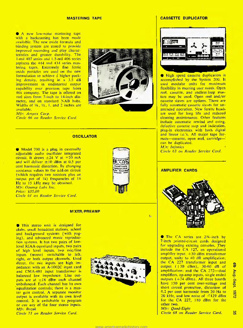
MASTERING TAPE CASSETTE DUPLICATOR
HI A new low-noise mastering tape with a backcoating has been made available. The new oxide formula and binding system are stated to provide improved recording and play charac- teristics and greater durability. The 1-rml 407 series and 1.5-mil 406 series replaces the 444 and 434 series mas- tering tapes. Extremely fine ferric oxide particles are used on the new formulation to achieve a' higher pack- ing density, resulting in a 3.5 dB improvement in undistorted output capability over previous tape from this company. The tape is olTered on reel sizes from 7-inch to 14-inch dia- meter, and on standard NAB hubs. Widths of V4, !/2, 1, and 2 inches are available. Mfr: Ampex Corp. Circle 66 on Reader Service Card.
OSCILLATOR
41 Model 700 is a plug in externally adjustable audio oscillator integrated circuit. It draws ±24 V at ±20 mA and will deliver ±10 dBm at 0.5 per cent harmonic distortion. By changing tesistance values to the add-on circuit (which requires two resistors plus an output pot of Ik) frequencies of 16 Hz to 15 kHz may be obtained. Mfr: Opamp Labs Inc. Price: $35.00 Circle 6! on Reader Service Card.
T'o OsciH® ^odel rOO
MIXER/PREAMP
9 This stereo unit is designed for clubs, small broadcast stations, school and background systems (with pag- ing), and advanced music reproduc- tion systems. It has two pairs of low- level RIAA-equalized inputs, two pairs of high level inputs, two mic/line inputs (mono) switchable to left, right, or both output channels. Used direct, the mic inputs are high im- pedance; with an A-1002C input card and CIV1A-48I input transformer is balanced low impedance. Line out- puts are at ±18 dBm each channel unbalanced. Each channel has its own equalization controls; there is a mas- ter gain control. A separate monitor output is available with its own level control. It is switchable to program or cue any of the four stereo inputs. Mfr: Bozak Circle 71 on Reader Service Card.
1
• High speed cassette duplication is accomplished by the System 200. It used modular units for maximum flexibility in meeting user needs. Open reel, cassette, and endless-loop mas- ters may be used. Open reel and/or cassette slaves are options. There are fully automatic cassette slaves for un- attended operation. New ferrite heads are used for long life and reduced cleaning maintenance. Other features include automatic rewind and cuing, defective cassette stop and indication, plug-in electronics with both digital and linear i.c.'s. All major tape for- mats—cassette, open reel, cartridge— can be duplicated. Mfr: Infonics Circle 63 on Reader Service Card.
AMPLIFIER CARDS
• The CA series are 2%-inch by 7-inch printed-circuit cards designed for upgrading existing consoles. They include the CA 127, an operational amplifier input, +30 dBm transformer output, unity to 40 dB amplification: the CA 227 transformer input and output (+30 dBm), 30-60 dB of amplification; and the CA 272—dual amplifiers, op-amp inputs, single ended outputs ( + 24 dBm). All three boards have 150 per cent over-voltage and short circuit protection, distortion of 0.2 per cent harmonic from 20 Hz to 20 kHz, and low noise of - 129 dBm for the CA 227, 110 dBm for the other two. Mfr: Quad-Eight Circle 68 on Reader Service Card.
www.americanradiohistory.com

UP TO
6 5 V.
SA VINGS
Plus performance that is creating excitement in Engineers around the country! Fantastic sound" . .. " Very Clean"" . . . "Superb! . . . Send two more . . . " Proof? Our standard 10 day evalua- tion period lets you see and hear the performance and the full serv- ice. 2 year warranty demonstrates the reliability. Place your order today. Then pre- pare yourself for a very satisfying experience!
TURNTABLE PREAMPLIFIERS
IVIP-8 (Mono) S60 SP-8 (Stereo) S90
Outstanding sensitivity and near per- fect reproduction. RIAA/NAB equal- ized 0.5 mv sensitivity @ 1 KHz for 4 dbm out — Balanced 600 ohm out — minus 65 db S/N ratio —
20 dbm out max — 1 db freq. response — Internal power supply — Table top/bracket mount. Ship- ping weight. 312 lbs.
MIC/LINE AMPS
MLA - 1 (Mono) S68 MLA- 2 (Dual) S96
Dual function utility amp. Inputs for mic and/or line — 600 ohm bal- anced outputs — mic input. 65 db for 4 dbm out — 20 dbm out max. — 0.5 db response. 10 Hz-20 Khz — 0.1% or less dist. — Internal power supply — Tabletop/bracket mount. MLA-2. Stereo/Dual Mono. MLA-1. Mono. Shipping weight. 4 lbs.
DISTRIBUTION AMP 6 BALANCED OUT
DA - 6 S95 One third the cost of comparable units. Six 600 ohm balanced outputs — Balanced bridging input — 26 db gain — 20 dbm out max. — Input level control — 0.1% or less dist. —
0.5 db response. 10 Hz-20 Khz — Internal power supply — Tabletop/ bracket mount — Shipping weight. 4 lbs.
TAPE CARTRIDGE * LOADER (AUTOMATIC)
ACL - 25 S159
Precision winding without guess- work. Dial in the minute and/or sec- onds desired, throw switch to run. That"s it! The exact amount of tape is fed onto the cartridge hub to the second, and shuts off automatically. No waiting around, no guesswork and 1 sec. accuracy. Also has ex- clusive torsion control for proper tape pack and winding of various cart hub sizes. TTL digital control circuitry. Shipping weight. 30 lbs.
.t?
RAMKO RESEARCH 2552 "E" Albatross,' P.O. Box 6031
Sacramento, Calif. 95860 ( 916) 489-6695
POWER AMPLIFIER
9 The model 240 is a stereo power amplifier with 125-watts continuous power per channel over the 20-20,000 Hz range—-with both channels driven simultaneously. Relay operated pro- tective circuitry has been designed to prevent damage to output transistors, power supply, or speakers from ex- cessive levels of subsonic frequency. Rack adapters or a walnut cabinet are available for a variety of appearance requirements. Mfr: Maranlz Co. Inc. Price: $395. Circle 70 on Reader Service Card.
TAPE MAINTENANCE KIT
# QIVI-3 is a kit designed for main- tenance of tape machines. It contains products designed to provide a pre- ventive maintenance program to a recorder. Included are; QM-102, 2 oz. bottle of liquid head cleaner; QM- 301, splicer for '/i-inch tape; QM- 501, 150-inch roll of Mylar splicing tape; OM-201 wand head demagnet- izer; and OM-502, 6-inch cotton tip- ped sticks. Mjr: Norlronics Co. Inc. Circle 74 on Reader Service Card.
X-Y RECORDERS
# Models 7044A and 7045A are two new general purpose chart recorders. Model 7044A is a medium speed re- corder with a slewing speed of 20 inches per second, the model 7045A is faster at 30 inches per second. In- put range of both instruments is from 0.5 mV to 10 V, floating 500 V d.c. or peak a.c. The writing area is 10 by 15 inches. Standard paper is used. Mjr: Hewlett-Packard Price: 7044A-$I350; 7045A-$I675. Circle 64 on Reader Service Card.
SPEECH COMPRESSOR/EXPANDER
• The varispeech permits speech re- corded on tapes to be played back at any speed between half and two and one half time original speed without affecting pitch or speech identity. It uses a standard cassette operating at variable playback speed. Signal pro- cessing is electronic, using no moving parts other than the normal tape mo- tion. Mjr: Lexicon, Inc. Circle 73 on Reader Service Card.
Circle 52 on Reader Service Card
www.americanradiohistory.com

I
& $ $ Q a < ^ C C O
Before you purchase your hew console, think first of SPECTRA SONICS ....
QUALITY Guaranteed to outperform any console in the world in noise, distortion, frequency response, and peak overload.
RELIABILITY The Model 101 Audio Amplifier, the heart of all consoles, is guaranteed in writing by SPECTRA SONICS for a period of two full years against any defect.
For guaranteed performance and reliability in professional audio consoles contact SPECTRA SONICS at:
770 Wall Avenue Ogden, Utah 84404 (801) 392-7531
6430 Sunset Blvd., Suite 1117 Hollywoo0d, California 90028
(213) 461-4321
PECTRil \DNICS
ADVANCED Circ/t'k |c on Reader Service Card
www.americanradiohistory.com

JOSEPH MARRONE
How About
Some
Automation?
Tele Sessions
You're invited to use a brand new communications medium to build on the ideas in this article with a group of people as involved in the subject as you. By means of a new "elec- tronic meeting place" called db TeleSessions. you'll be able to dial into a group telephone conference with other db readers across the country. You can reserve your spot in the discussion now by turning to the inside back cover for details and information on how to participate.
Automation in varying forms is already available in the
audio profession. More is coming. But how is it applicable
to your needs? Do you need it? What might it cost? This
article covers it all.
Prouably the most significant event in the history of audio engineering was the marriage of elec- tronics to music reproduction. The application of vacuum tubes to the manufacturing of records
and the broadcasting of programs over the airwaves in the late I920's gave the infant electronics industry tre- mendous momentum. The vast consumer market poten- tial for radios, phonographs, and ultimately television, spurred the industry on and created a demand for better methods of producing and reproducing sound. Of neces- sity. the equipment used to do this became more and more sophisticated, especially within the recording studio and transmitter room. In parallel developments, both the audio and broadcasting segments of the industry moved forward in attempting to close the gap between real sound and artificially produced sound. With each technological advance in the science of music reproduction, the industry moved asymptomatically closer to that elusive thing called ultimate fidelity. Once a high degree of fidelity had been achieved, the industry reached out in new directions and made music reproduction into an art form.
As all this was taking place, the type of equipment used to record and reproduce sound became more complex at an ever accelerating pace. By the I960,s, the highly perfected electronic equipment needed for accurate sound production in recording studios had become orders of magnitude more complex and more difficult to use than its ancestors.
Many additional skilled people were required to oper- ate the newer generations of equipment. Entire staffs were needed to record a single performance, and to perform the work necessary to mix down the original material into a mass reproducible form. And somewhere in the never-ending attempt at perfection in sound reproduction, the time-honored techniques and machinery started to run into a man-machine interface problem. The prolifer- ation of equipment and people, all of which had to work in perfect synchronization and harmony, reached, or nearly reached, the breaking point. The audio industry had built up a system that, by its very nature, relied too heavily on the man, and taxed his capabilities to the point where he became the weakest component in the system.
Joseph Mar roue is a sales engineer with Digital Equip- ment Corporation.
Man was being called upon less as a creative entity within the system, and more as an automaton just to keep the system functioning.
During the years that electronic equipment in the audio/broadcasting field was being perfected for the highly specialized tasks that are unique to this industry, there were many parallel developments going on in other fields that involved electronics. Mass production techniques in automobile manufacturing became electrified, chemical processes were being controlled automatically by electronic systems, electronic guidance systems employing highly ad- vanced feedback techniques were enabling us to shoot rockets to the moon, and electronic computers were being developed to calculate our pay checks, our electric bills, and even monitor our heartbeats when all this madness drove us into a hospital. Indeed, electronics was being applied to virtually every field of endeavor in the arts, the sciences, in industry, and in the home.
Perhaps at this point, we should examine some of these other developments that have tremendously benefited other industries, and ask, "Can any of these technological advances in electronics be of any benefit to audio engi- neering and specifically, can they make the man-machine interface problem less burdensome to the man and free him to be more creative?" I believe the answer to this question is yes. Man-machine interface problems are not unique to audio engineering. They exist in all phases of industry and manufacturing. They exist in airplanes, in submarines, and in the manned space program. The general method of attacking this class of problem is to automate the machine as much as possible without taking ultimate control away from man. Automation in this sense means taking the "dog work" away from the oper- ator, thereby, giving him more freedom to operate the system to its fullest capacity. A side benefit of this kind of semi-automation is the elimination of subjective human errors that usually occur in the repetitive and lower level system functions. Now that we have come this far, it seems fair to state that the audio industry is ready for another marriage to the electronics industry. This time, the major concern will not be on better sound reproduc- tion, but on better utilization of existing equipment and manpower. The benefits of such a marriage will not be from a purely technical standpoint, but rather from a business standpoint, because if some form of automation is feasible, then increased efficiency and throughput should be possible, and this will directly affect profits.
www.americanradiohistory.com

When we think of automation, or more properly of semi- automation, there are several ways to proceed. Everyone dreams of the day when everything he must do can be accomplished by the push of a button. But in the context of our discussion, that represents an impractical form of Utopia. Hence, it is necessary to define some goal to which we can address ourselves; some readily obtainable objective that can be accomplished with a minimum amount of effort, a very high probability of success, and no ill effects on the present operation of the system. One of the dangers with proceeding too fast in the area of automation is that one tends to bite off more than one can chew: leading a noted philosopher to utter the unfor- gettable phrase "Most vast projects are usually started with half-vast ideas." So for openers, it is important to define the minimum identifiable task consistent with the three guidelines stated above. Instead of trying to auto- mate the entire operation all at once, with a 1 per cent probability of success, it makes much more sense to select a small, innocuous project that has a 90 per cent probability of success. In order of increasing complexity, here are some typical projects which lend themselves to automation.
Studio Control. Provide a better method for playing tape cartridges. Use of a conductive band on the tape would enable accurate timing of the upbeat, and provide a means of cutting microphones in and out at the proper time.
Tape Recorder Control. Provide a means for auto- matically starting several tape recorders that must be accurately synchronized. This will be of benefit for dub- bing, punching in, mixing, etc.
Automatic Transmitter Switchboard. Provide a system that monitors transmitters A and B, and automatically switch one to full power if the other fails.
Generation of FCC Log. Provide a means to monitor all important transmitter parameters automatically, and print out the FCC log without operator intervention.
Improvement of the Mix-Down. Provide a means to '"remember" the fader, echo send, pan pot, and other parameters associated with the mix-down process so that the operator doesn't have to commit everything to memory.
Network Control. Provide a system that stores a day's programming and automatically switches the outgoing audio (and video) continuities at the proper times and performs the functions of pre-roll, wipe, cut and dissolve.
In each case, the important concept is to place actions of a purely mechanical nature under automatic control, while actions involving judgment should remain under control of an operator. To automate a system requires us to have full knowledge of the normal as well as the abnormal sequences of operation of the system. Once defined, we can design some kind of black box to per- form this sequence of operations. Analog techniques, digi- tal techniques, or some combination of the two will per- mit us to design what we need. Analog techniques are familiar to those who have had experience in feedback control such as is commonly found in operational ampli- fiers, servomechanisms, etc. Digital techniques were first employed using relays, switches, and timers. Today, most digital systems are of solid-state design. The digital sys- tem possesses several characteristics that make it ideal for automation purposes.
Decision-making Ability. Digital circuits can make elementary decisions about a system based on the inputs, and perform some action that depends on the decision. The basic decision making element is referred to as a gate, and gates are combined to form logic circuits that make higher level decisions.
Memory. Digital circuits can be made to remember some past event or data. This means that the system can
IMDI ITQ
Figure 1. An automated transmitter switchover system.
look back and see a "snapshot" of some portion of past history.
Sequential Operation. Digital techniques make it easy to perform sequences of operations whereby the termina- tion of one event causes the next event to start. Digital counters, shift registers, and one-shot multivibrators are all used for this purpose.
The proper combination of logic circuits, memory, and sequential circuits enable the designer to build digital systems that can perform a given set of tasks. The more flexible and changeable we make the system requirements, the more complex the logic becomes. As systems increase in complexity, it soon becomes obvious that a digital system must have some means of easy modification so it can be made to do any number of different jobs. This is precisely what led to the development of the small general-purpose computer. A computer is nothing more than a collection of general-purpose logic circuits and memory combined in such a way that one can program the job to be done by putting certain commands in memory. During execution of the program, these com- mands are interpreted by the logic circuits, resulting in a sequence of events similar to that achieved with ordinary digital systems. The big difference is one of flexibility, and the decision to use a straight digital circuit or a com- puter involves a trade-off on the cost of implementation versus the flexibility of the resulting system.
Let's examine some of the relative costs of specially designed digital systems (often referred to as hard-wired logic systems) and small computers. While each appli- cation must be evaluated on its own merit, there is a general rule of thumb that hard-wired systems fit into the under $5,000 category. The availability of small com- puters in the $5,000 price range make it impracitcal, for the most part, to build special purpose digital systems that cost more than this, when for the same price, or slightly more, one can purchase a small computer with much greater flexibility. On the other hand, a program- mable computer does require a programming effort that costs money, and this must be taken into account when estimating the total cost of a job. The important thing to remember is that programming changes do not require us to cut wires, add parts, or change schematics; all of which must be done when trying to modify a hard-wired logic system. So there is a trade-off between the ease of
www.americanradiohistory.com

OUTPUT
Figure 2. A small computer could control a complete radio station.
modification and cost of modification. The price of a small computer system is affected by several factors. Some of these are as follows;
The size of the memory required to do the job. The requirement for additional bulk memory (often
called mass storage). This is available in several forms such as magnetic tape, magnetic disks, and magnetic drums.
The need for special circuitry to interface the com- puter signals to the audio equipment being monitored or controlled. Much interface hardware, such as analog- to-digital converters, digital-to-analog converters, and on/ off devices such as relays are available off-the-shelf and make most interfacing jobs fairly easy.
The need for special operators' consoles to operate the computer system and give it commands.
Putting all these factors together, we can talk about a minimum practical price of a small computer with mem- ory and some interface equipment of about $7500. Sys- tems in the range of $7500 to $20,000 might be typical for a majority of applications in audio engineering, while for certain specialized tasks price could range as high as $50,000 to $100,000. These prices are all subject to radical change as electronic technology progresses, but the relative magnitudes will stay fairly constant.
Let's examine two typical systems to see how both hard-wired logic and small computers can be applied to specific tasks. Figurf. I shows a typical transmitter sys- tem in which amplifiers A and B normally operate at half power. If either A or B should fail, the switches P. Q, and R would eliminate the bad amplifier from the system and leave the good one on the air. Then the good amplifier would be boosted to full power. This can all be accomplished automatically by monitoring the status of each transmitter. Such parameters as plates on, fila- ments on, plates ready, driver overload, etc. would be inputs to the logic system, which monitors them on a continuous basis. The detection of a failure in any of these conditions would be interpreted by the control logic, and the appropriate action taken, such as shutting down the bad transmitter and bringing the other up to full power. The same type of monitoring can be used on the two exciters, and provision made to switch the back-up exciter onto the system should the primary exciter fail. The en- tire control system to do this type of job can be built using off-the-shelf plug-in modules. Eeverything including
the logic gates, power supplies, mounting hardware, a.c. and d.c. input and output adaptors are available today at reasonable prices. Very little special design, if any, is neces- sary to build such a system. Some people refer to this equipment as an "electronic erector set." Once the logic circuit is designed, it can be built from standard printed- circuit cards, which plug into sockets that have been wired for the particular job. This is a very modular ap- proach and allows relatively easy field modification of the equipment. Also, time to repair will be low because rela- tively few types of modules will have to be kept in spare parts inventory.
The inherent flexibility of a small computer in forms of control operation make it a natural choice for many forms of audio automation. Returning to our example of a radio station, while a hardware logic controller would be useful for such a simple operation as monitoring the performance of transmitters and adjusting them to satisfy particular conditions, how about the more general prob- lem of station operations? Obviously, the problems in- volved for such a function—essentially, augmenting the work of the station engineer—are considerably more sophisticated than those for the more straightforward one of transmission control. Here we require a system that is able to make rather sophisticated judgments, that is reasonably flexible about how it is going to achieve its ends, and that is "smart enough" to be able to call for help when it runs into a problem beyond its capacities.
Such a system will have to monitor and correct trans- mitter power output, check for frequency drift and cor- rect for any deviations beyond the established limits, monitor and be prepared to accept any emergency inputs such as Civil Defense information, check component per- formance to determine whether any malfunctions have occurred that would affect output performance {e.g. an overmodulated signal), and keep a record of station per- formance.
Such a system would be built around a small computer. And here we can see how a small computer can act in a partnership with simpler logic systems, for the subsystems used for regulating the transmitters would be virtually identical to the system described above. The only differ- ences would be that there would be monitoring outputs from the control unit to the computer, and control out- puts from the computer to the system. Other aspects of the system would not be quite the same as the control
www.americanradiohistory.com

circuit for the transmitters; a diagram of such a system is shown in Figure 2.
[n addition to the control system for the transmitters, a similar control system would be devised to control the program source (i.e.. whether information is to come from stored tapes, from live studio operations, or from the Civil Defense announcer). In the control system, other parameters, such as relative audio levels, degree of source modulation, and the like, could also be monitored and corrected if necessary.
For the audio amplifier, its performance could be moni- tored by the computer through an analog-to-digital inter- face. Corrections, if required, would be supplied by the computer through control signals transmitted via a digital- to-analog converter.
Program schedules could be stored in the computer's mass storage device, which could be either magnetic disk or tape; standby alternatives could be kept in reserve for program emergencies. Also, data could be stored on this mass storage device for later analysis—either directly, or as a printout. By correlating actual events such as a time standard or internal clock, this stored information could form the basis for a comprehensive station log.
And finally, the line from the Civil Defense network could be monitored for possible use. If the correct infor- mation was received by the computer through a com- munication line, it would activate the special unit that would broadcast the alert and instructions.
And because of the sophistication of the programming, the minicomputer could signal the engineer through some input-output device, most probably the unit's Teletype.
The computer is ideally suited to remember all those operating procedures that one must now commit to memory. Again, there is a great amount of standard equipment available today to do these jobs, and the cus- tomized interfacing between computer and system can be kept to a minimum. And although it might be possible to construct a similar device out of logic gates and mem- ory, thus making it a hard-wired logic system, hard-wired systems of this magnitude tend to be horrendously expen- sive. Also, such systems are difficult to justify unless a convenient means has been provided for checking them out if they malfunction. Another important justification for using a computer in this application is the ease of checkout by means of special programs called "diagnos- tics." These programs can help pin-point problems in the system, and most important of all, could be incorporated into the regular computer routine to do periodic checks on the status of the equipment. This feature is fairly easy to do with a programmable computer, and extremely difficult to achieve in hard-wired logic. In addition, changes of the system's performance characteristics are much easier to implement by developing and reading in new programs as opposed to having to make physical hard- ware changes. To be sure, we have only touched the sur- face of sudio-engineering automation. Obviously, even the simplest of projects requires a great deal of thought to determine the best way of doing the job. The intention here has been simply to indicate typical systems-level approaches that can be employed. Solid state logic, mini- computers, and interfaces are new tools available to audio engineers and technicians. They are here today, offering off-the-shelf solutions to many problems. So per- haps in the near future you will discover that your pet project has a natural—and inexpensive—solution through automation techniques. ■
ACKNOWLEDGEMENTS
Eric Small, chief engineer—WOR-FM irv Joel, chief engineer—A & R Recording Studio
A
Stainless
Steel
Stradlvarius
it isn't, but that's the closest we can come to de- scribing the new Infonics Professional Dupl eating Systems 200. They produce 10 to 15,000 Hz ± 3 db on cassettes... an octave jump in band width. Building-block modularity gives them flexibility so great no ad can describe it.
Systems 200 have endless loop, reel-to-reell, and cassette master modules, reel and cassette slaves, even fully automatic slaves for unattended opera- tion. Ferrlte heads for 55,000-hour life. 1.5 MHz. bias. Produce 4 to 100 C-40's in 1.9 minutes. Auto- matic rewind and cueing. Defective cassette stop and indication.
Plug-in electronics with both digital and linear IC's. 55 db crosstalk. Heavy-duty professional decks. 100% vibration test for reliability. The only non- professional feature is Systems 200's price., .you'll be amazed! And they're in production right now. Phone or write for your 10 to 15,000 Hz. demo cassette and our spec sheet — all 12 pages of it.
Infonics, Inc., 1723 Cloverfield Boulevard, Santa Monica, California 90404, phone 213/ 828-6471, Cable Address; Infonics
a. u > C. CO CO CD "a
CO -si ro
Circle 28 on Reader Service Card
Reel master, Cassette and Auto-Slave . . . three of the seven Systems 200 modules.
infonics. systems 200
www.americanradiohistory.com

RICHARD FACTOR and STEVEN KATZ
Automatic
Tape Transport Control
Several automatic tape search units are now available.
One such unit, available from Amp ex, is described. The
applications of this sort of device may be endless.
It is 2:30 in the morning and you've been in session since 3:00 the previous afternoon. The producer looks into your glassy eyes and says sincerely, "OK ... let me hear the beginning of take 20, the
bridge of take 7, and the ending of take 17." Only 2500 feet of tape separates you from a good night's sleep.
In prehistoric days, {i.e., before 1970) finding the re- quisite selections would have involved searching for each slate, finding it, and then waiting for the appropriate section. You can skip ahead to find the section, but are you sure you're still in the right take?
Within the last three years, the major professional tape recorder manufacturers have introduced various electronic devices to simplify and speed up this time consuming task. This article will discuss the method of operation and applications of these devices.
Basically, the new devices are digital counters which are coupled to the tape by electro-mechanical sensors. They give an indication of how much tape has passed the heads from the feed to the take-up reel. The least com- plex of these units counts the number of tape turntable revolutions and gives an index number proportional to the number of revolutions. Other units are capable of automatically shuttling the tape transport back and forth to reach a number which can be preset from the front panel.
At least one of these units, the Ampex Tape Search and Control unit, is capable of measuring the elapsed time of the tape in minutes and seconds and searching for any location on the tape to the nearest second.
The authors were responsible for a digital delay line ar- ticle that appeared in May. Steve Katz is chief engineer of Sound Exchange Studios in New York City. Richard Factor and Mr. Katz. are both v.p's of Eventide Clock- works. Inc.
Using such a device in the session alluded to enables you to find takes 20. 7, and 17 just by dialing in the start- ing time of the take and pressing a button. The engineer is now free to fill in his take sheet, move a microphone, readjust levels, or what have you. while the tape transport automatically cues itself.
HOW IT WORKS
The heart of the tape search and control unit is the counter/memory which determines the current tape lo- cation. (see Figure 1). This circuit is comprised of sev- eral integrated circuits which accept input pulses and count up or down depending upon the direction of tape travel. The total number of pulses (up counts minus the down counts) is stored and sent to the display and com- parison circuitry. It should be noted that one reason these search units have come out so recently is that the cir- cuitry involved in just this counting/storage function would previously have required a rack cabinet full of equipment.
TeleSessions
You're invited to use a brand new communications medium to build on the ideas in this article with a group of people as involved in the subject as you. By means of a new "elec- tronic meeting place" called db TeleSessions, you'll be able to dial into a group telephone conference with other db readers across the country. You can reserve your spot in the discussion now by turning to the inside back cover for details and information on how to participate.
www.americanradiohistory.com
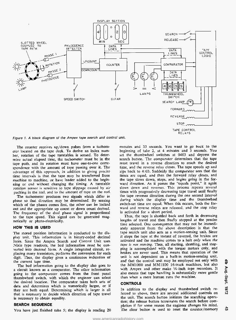
DISPLAY SECTION
SLOTTED WHEEL COUPLED TO TAPE PATH
o 4 1 2 0
o —v M1N SEC
"APE CONTROL
LOGIC
TAPE CONTROL RELAYS
Figure 1. A block diagram of the Ampex tape search and control unit.
The counter receives up/down pulses from a tachom- eter located on the tape deck. To derive an index num- ber, rotation of the tape turntables is sensed. To deter- mine actual elapsed time, the tachometer must be in the tape path, and its rotation must have one-to-one corre- spondence with the amount of tape passing over it. The advantage of this approach, in addition to giving precise time intervals is that the tape may be transferred from machine to machine, or have leader added to the begin- ning or end without changing the timing. A turntable rotation sensor is sensitive to tape slippage caused by air packing in the reel, and to the amount of tape on the reel.
The tachometer produces two signals which differ in phase so that direction may be determined. By sensing which of the phases comes first, the other can be locked out and the appropriate up count or down count derived. The frequency of the dual phase signal is proportional to the tape speed. This signal can be generated mag- netically or photo-electrically.
HOW THIS IS USED
The stored position information is conducted to the dis- play unit. This information is in binary-coded decimal form. Since the Ampex Search and Control Unit uses Nixie type readouts, the bed information must be con- verted into decimal form. A single integrated circuit, re- placing many transistors, performs the conversion for each digit. Thus, the display gives a continuous indication of the current tape time.
The bed information going to the display also goes to a circuit known as a comparator. The other information going to the comparator comes from the front panel thumbwheel switch, with which the engineer can select the desired location. The comparator takes both sets of data and determines which is numerically larger, or if they are both equal. Determining which is larger is all that is necessary to decide which direction of tape travel is necessary to obtain equality.
SEARCH SEQUENCE You have just finished take 5; the display is reading 20
minutes and 33 seconds. You want to go back to the beginning of take 2, at 4 minutes and 3 seconds. You set the thumbwheel switches at 0403 and depress the search button. The comparator determines that the tape must travel in a reverse direction to reach the desired time, and the reverse relay closes. The tape speeds up and zips back to 4:03. Suddenly the comparator sees that the times are equal, and then the forward relay closes, and the tape slows down, stops, and begins going in the for- ward direction. As it passes the "equals point," it again slows down and reverses. This process repeats several times with progressively decreasing tape travel until finally the tape reverses direction during the one second interval during which the display time and the thumbwheel switch-set time are equal. When this occurs, both the for- ward and reverse relays are released, and the stop relay is activated for a short period.
Thus, the tape is shuttled back and forth in decreasing lengths of travel and then finally stopped at the precise time selected. One consequence that may not be immedi- ately apparent from the above description is that the tape search unit also acts as a motion-sensing unit. Since it stops the tape at the instant of reversal, the brakes are activated and the machine comes to a halt only when the tape is not moving. Thus, all starting, shuttling, and stop- ping is accomplished with the torque motors only, and brakes are never used. This means that operation of the unit is not dependent on a built-in motion-sensing unit, and that the control unit may be employed not only with the MM1000 and MM1100 16-track machines, but also with Ampex and other make V^-inch tape recorders. It also means that tape handling is substantially more gentle than when a mere human runs the machine.
CONTROLS In addition to the display and thumbwheel switch re- ferred to above, there are several additional controls on the unit. The search button initiates the searching opera- tion; the release button terminates the search before com- pletion if for some reason the engineer changes his mind. The clear button is used to reset the counter/memory
a. o- > c (Q 'l CO CD TD
CD -si ro
CO
www.americanradiohistory.com

t* L-U •
Figure 2. The search unit.
either at turn on or the beginning of a tape. This, in ef- fect, can be used to set a reference point as described later. The 15/30 or IVi/XS in/sec switch is set to the current speed of the tape transport, to assure that the timing information will be correct.
Several indicator lamps other than the display are provided, two to indicate in which direction the tape must travel to reach equality, one to indicate when the times are equal, and one to indicate when an actual search operation is occuring.
Since the tape search and control unit can be used with virtually any professional tape recorder, a panoply of applications suggest themselves. In addition to uses in re- cording studios, there are uses in broadcasting, cutting studios, film work, and others. We will take these in order and give some suggestions and applications in each field. After that, we will discuss some of the future possi- bilities in automatic tape control, using both search units and other devices and techniques.
RECORDING STUDIO APPLICATIONS In a typical recording session, the search unit would be used for timing and control functions. After breaking out a new reel the tape would be advanced about one minute in and a grease pencil or splicing tape mark would be made. This mark will henceforth and for all time be the permanent reference for the tape. All time markings written down for permanent record will be elapsed time from this mark. This mark is centered over the play head and the "CLEAR" button on the tape search/control unit is depressed, setting the time to 00:00.
As the session progresses, each take beginning is
Figure 3. On an Ampex MM-1000 the arrow points to the tachometer.
marked on the box or take sheet. If it is necessary to go back to any take, this time record gives the thumbwheel switch setting necessary to go to the top. Likewise the time within the take can be noted for each musical fea- ture. Thus if a return to the first bridge is desired, it can be precisely returned to, with no danger that it's ac- tually the second bridge. If it is desired to work with one take, the zero can be reset to its beginning, and a little mental arithmetic (adding the starting time to the time into the take) can be obviated.
BROADCASTING APPLICATIONS The broadcast industry is more accustomed to auto- mation than the recording industry. Frequently entire sta- tions" air operations are automated, from music selection to logging. And yet, the day-to-day operation of stations in production, news gathering, air checking, etc., is almost inevitably manual.
A common procedure in station news rooms is to pro- vide a tape to record telephone conversations, both for broadcast and legal records. Typically a day's worth of conversations will be recorded, and the news editor will later abstract one section of one or more conversations. Marking the tape time of each cell or event will allow instant location. Trying to wind back to the appropriate flag more often than not just leaves a problem for the janitor (and in a small station, the engineer is the jani- tor). Locating spots in an air check is another possible application, when the dj starts a segment, he can put a tape up and record the show from then on, logging the starting time of the tape on the box. If it becomes neces- sary to locate a spot for a sponsor (or a violation for the FCC), it is just necessary to put the tape back on and run it to the proper time. For operations with little co- hesiveness in programming (top 40 rock, for instance), where almost every segment is under three minutes, and most are only seconds, it saves a lot of time to find things right away.
Having bi-directional search capability with thumb- wheel switch control allows one to select a given time even if the tape has not already been at that location, facilitating this task.
OTHER APPLICATIONS The timing function alone is of inestimable value in an operation such as a cutting room, in which tape timing is necessary. Say an album is sent over with no timing information. The engineer must know how long the cuts are to determine the level and pitch at which the disc must be cut. Unfortunately, timing normally takes just as long as cutting, raising the cost of the operation in- tolerably. With the tape search unit in the timing mode, determining the length of the tape takes no longer than running it fast forward to the end and reading the dis- play number. Also, if the tape is unleadered, one knows when to spiral by timing information alone.
So much for the current applications of the tape search unit. The list is not exhaustive, but it does show some of the things that you can apply it to in your field.
POSSIBILITIES IN AN AUGMENTED SEARCH SYSTEM None of the devices to be suggested are offered for sale by any manufacturer, but they are all possible with modi- fications to the basic unit, and do not require any par- ticular advance in the state of the art before becoming feasible.
A simple auxiliary circuit would enable one to store location information in a random access memory. It would be possible to, say, log the location of each selec- tion directly in the search unit, simply by pressing a key
www.americanradiohistory.com

corresponding to the selection number and simultaneously depressing the "store" button. Depressing the number key and the "retrieve" button will automatically send the tape back to the top of that selection. This has applica- tions in recording, broadcast automation, etc. . . . For tape interchangeability, a small magnetic card reader could store and transfer this time data from one search unit to another. The magnetic cs.d would go in a little pocket on the tape reel or in the box.
Adding a keyboard and a slightly more complicated memory would enable one to partially automate the mix- down function. For instance, if it is desired to mute a track because of noise during some period, one would enter in the time out and lime in for that track, along with the track number or some identifying code. This application is obviously not limited to muting tracks—any- thing that must be done during the tape playback can be programmed into the memory. The amount of data stored is not limited by the capacity of any code recorded on the tape, as, indeed, no code is recorded, thus saving the track for musical information. Also, there is no leakage problem between an encoded track and a recorded track.
One might think that a one-second resolution would be inadequate for this application. However, the tachometer on the tape deck actually puts out 48 pulses per second (at 15 in/sec), thus dividing the entire tape into ap- proximately 20 millisecond increments. Any one of these may be selected for an event to occur.
One slight disadvantage of this system when compared with a tape-encoding scheme is the possibility of tape slippage. The tachometer is normally in perfect contact with the tape and no slippage occurs. However, in fast forward or rewind, a small error is possible, especially if there is paper leader in the tape. This error is rarely more than a second, which is irrelevant in normal opera-
tion, but critical in a mixdown application. If it is neces- sary to rewind to a precise spot, a small piece of alumi- num foil can be placed at the precise beginning reference and this be either found photoelectrically or used as the start reference.
Sometimes it is desirable to synchronize two or more tape machines to allow additional tracks to be recorded. The normal procedure for doing this is to record both tapes with the SMPTE time code and have two time code readers compare the tapes and adjust one to the other. This works very nicely, but costs about ten thou- sand dollars. An alternative is to use two search units and a photoelectric strip as described above to start the tapes simultaneously. If the two tape machines have d.c. servo control, they can be locked by running both ma- chines from one control track. A completely electronic positioning system not requiring a time code is under development.
Certain accessories to enhance tape search unit opera- tion are possible. For instance, remote readout units can be employed to indicate to the performer and producer the elapsed time from the beginning of the tape. Such a remote unit can work in several modes—it can be slaved to the main unit and read the same time, or it can be reset independently and provide an elapsed time from the beginning of a take while the master unit will preserve the absolute time.
We have described some of the applications for auto- matic tape search and control equipment. Low cost, ver- satile equipment of this nature has recently been ren- dered possible by the decreased cost of complex inte- grated circuits. As this trend continues, we anticipate the introduction of digital equipment with built in calcula- tion or computation functions, as well as other more elaborate functions yet unanticipated. ■
Auditronics, Inc. presents a sneak preview
"/on of 56 GrancT
Coming to your neighborhood studio soon (Rated R)
Here is poetry in sight and sound for recording studios that want 16 track recording capability, with real life performance and economy in
one console. All from a manufacturer with over five years experience producing big budget recording systems and consoles.
Auditronics "Son of 36 Grand" is a second generation Profes- sional Audio Control Console, five years in the making, that puts
16 track capability within the economic range of every studio. A recording console that provides 16 in, 8/16 channel
output, full quadraphonic capability, and complete monitor- ing flexibility for both recording and mixdown, normally
would set you back about $36,000. But the action packed "Son of 36 Grand" gives you all this at less than half
the price! To get your pass for a backstage peek at specs on
this rising new star, just drop a line to Auditronics, P.O. Box 12637, Memphis, Tennessee 38112 .. the people who brought you "36 Grand" and
many other stupendous extravaganzas.
See the Son of 36 Grand at the Fall A E S
Convention
ouditronlcs. inc. MEMPHIS TENNESSEE
Circle 44 on Reader Service Card www.americanradiohistory.com

WALTER JUNG
Automating the Audio
Control Function, part 3
Ongoing applications of digitally programmed switches
(dps) - a subject particularly of value to the audio
pro that is beginning to become involved with
some aspects of automation.
Last installment we began to apply the dps to switching and control of audio signals, and ex- plored a number of configurations. Since we left off on switching matrices, this would be a
natural point of departure into the next series of ap- plications.
It turns out that the factors* that make the dps switch- ing structure a natural one for switching bus and matrix applications also lend it well to related applications—as digitally programmable attenuators and amplifiers.
Figure 1(A) is a sketch of the basic scheme in which the dps can be used as a programmable attenuator. Switches S1-S"N" are the digitally-controlled switching elements, here shown as ideal switches. Each switch con- trols an input current which will be in proportion to Ein and its respective input resistance. For any combination
Rf of S1-S"N" on conditions the net gain will be, where
Rf is the feedback resistor and Req is the equivalent par- allel resistance of the switching network. In effect this stage is a special case of a switching summing amplifier, where instead of a number of different audio lines being switched and mixed, we have a single audio line being switched through parallel paths, with different weights for each switch combination, thus changing the net gain.
The configuration is a flexible one, as any desired gain range and gain per step may be selected by choosing the appropriate resistance ratios and number of steps. Figure 1(B) illustrates how this would be accomplished using a number of dps switching elements, 1-"N." The total range of gain change will be: AAv total = AAv per dps xN where N = number of switches, AAv = gain change per switch and AAv total =
total gain change Thus, for instance, a gain change of 60 dB would re- quire 6 switches of 10 dB steps or 10 switches of 6 dB steps—depending on how fine you want your steps. The beauty of this system is that you can readily manipulate it to suit differing requirements. An example is Figure 2.
It is quite interesting to note what you can do with a programmable attenuator such as this. When fed a digital word such as might be generated during an automated mixdown process, a digital attenuator can directly perform the attenuation function without the intermediate hard- ware steps of digital to analog conversion and voltage con- trolled amplification. An interesting and useful side benefit
of this approach would be a direct readout of attenuation in dB via l.e.d. indicators driven from the storage register driving the digital attenuator. A block diagram of this system is shown in Figure 3.
Dps elements may be used within an amplifying feed- back loop as well as at the input as described in Figure 1(B). Figure 4 illustrates how this is done in another gain ranging circuit. In effect all we have done is recon- nect the input of the dps bank to the amplifier output, and feed our input signal to the summing junction via a single fixed resistor. The effective feedback path is varied by the circuit of Figure 2. The end effect is quite differ- ent however, as in this case gain is raised as the dps's open, the direct opposite of Figure 2. This then is a pro- grammable gain amplifier.
Figure 1. (A) is a programmable attenuator. (B) is the dps programmable attenuator.
Em >
(A)
Rf
A Em = EQUIVALENT INPUT RESISTANCE
OF R, , Rj , R3 8 R'v
"see appendix of "Automating" Part 2 iB)
www.americanradiohistory.com

Figure 2. A programmable attenuator. A practical example of the attenuation technique we've been dis- cussing is shown in this figure. Here three dps switch- ing elements are set up for a total gain change range of 60 dB, ranging from 0 dB insertion gain (all switches on) down to —60 dB gain (all switches off). Signal han- dling capability is +20 dBm at both input and output, distortion less than 0.05 per cent, and with a low-noise op amp for A1, s/n can be in excess of 90 dB at max output. The gain state of the attenuator is under con- trol of the three digital lines (1 per switch) with con- trol logic as in Table I.
Gain is set by the ratio of the combination of Rin re- sistors to Rf (in this case RB). With all three dps ele-
R8 20 K 1 ments off, gain is or which is or
Rin1 20 M 1000
—60 dB. Switching on DPS1, changes this to —40 dB, with DPS1 +DPS2 it becomes —20 dB, and with all three dps elements on gain is 0 dB.
Several features of the circuit are worthy of note for those who might want to duplicate or modify it to suit special needs. One of them is the decoupling from the -|-15-volt supply line, provided by R3-R4, the split
d.c. load return resistors. The decoupling is absolutely necessary unless the supply used has virtually zero impedance at signal frequencies, otherwise the off sig- nal at each switch (which appears at 02) will develop a signal across this impedance and feed it into the op-amp summing junction. This will ruin the otherwise excellent on-off isolation of the switches. It might be well to remember that we're talking here of a switch isolation capability of 100 dB—you just can't take lib- erties and realize this kind of performance!
Another point is a side effect brought about by the busing of dps outputs. Since a dps output is in actuality the output of an amplifier stage, (this is true regard- less of the state of the switch) it follows that it does generate noise components. This is a point to be con- sidered when adding units together in bus fashion, as the total system noise increases each time an addi- tional dps is added in parallel. Noise from a dps is caused primarily by the reference current generator which is fed by ls. Therefore for low-noise applications, bypassing the ls terminal (C3, C4, C5) to —V is recom- mended to minimize this current noise, as well as operating at minimum possible ls. By using this tech- nique in the circuit of Figure 2 a noise level of —80 dBm was achieved.
Table 1. Control states of Figure 2 attenuation characteristics.
Control Bits Gain 1 2 3
—BOdB 0 0 0 —40dB 1 0 0 —20dB 1 1 0
OdB 1 1 1
A good application for this technique is as a "distor- tionless" age system, shown in Figure 4. Here a number j? of dps elements are arranged to switch the negative "P feedback applied around amplifier Al. The number of O) switches would correspond to the age range desired and -o gain change per step (as in Figure 2). Gain change points are determined by a number of level comparators co which sense the relation between the input level and a tu series of reference voltages. The input signal is level de- tected by an appropriate detector (peak, rms or what- ever form of control response is desired) and fed to the comparator bank. As the input rises, it will progressively -vi
www.americanradiohistory.com

Figure 3. A digital attenuator with an led readout.
become greater than reference voltages El-E"n." as it passes each level, the comparator outputs change state, activating the dps's and reducing the gain. So, although the input may be constantly changing, the output will stay constant (as long as the input stays within the switch- ing dynamic range of the system). A useful auxiliary feature would be a sequential l.e.d. gain-reduction readout driven from the control logic as shown.
An interesting variation on the level sensing gain rang- ing amplifier is a level sensitive gating circuit used to key program material on or off above a predetermined threshold. A block diagram of this is shown in Figure 5(A). The system is similar to Figure 4, except for the fact that it uses a single gate function and a variable gain preamplifier preceding the level detector. Figure 5(B) is a working circuit of such a system, with a detailed de- scription of the individual elements.
Obviously, the uses you can find for a gating system like this are numerous. Careful control settings will al- low undesired background noise to be keyed off while allowing desired material to pass. Or you can slave a number of gates to a common master which can switch the others on or off by appropriate choice of control logic. A single device may be used for either expansion or compression by driving the auxiliary input with a higher (expansion) or lower (compression) level signal. You can key in a special effects signal on the auxiliary input to get some spectacular effects as the unit switches into the auxiliary channel and keys on the "doctored" signal.
Generally the circuits we have been discussing in this installment have centered around digitally-controlled am- plifying circuits. We have seen how they may be imple- mented in a number of ways. A natural extension of this
CM r- cr>
o. 0) op d) < ■O ■o
00 ■t
Ein
Ein>
Rf(eq) AV - — „ H WHERE Rf (eq) R m = EQUIVALENT FEEDBACK RESISTANCE
OF Rf i , Rf 2 B Rf "n"
(A)
Figure 4. At (A) a programmable gain amplifier using dps elements in the feedback loop. At (B) is a distortionless age system with led gain reduction readout. (B)
www.americanradiohistory.com

convention
olive
Olive Electro Dynamics Inc. 2670 Paulus Montreal 386, Quebec Canada (514) 332-0331 Cable Olivel, Montreal
Westlake Audio Inc. 6311 Wilshire Blvd. Los Angeles, California 90048 (213) 655-0303
Studio-Technique 4 avenue Claude-Vellefaux Paris (lOe) France 206-15-60/208-40-99
You'll find the Olive Series 2500 multi-track recording console in the AES Convention at the Waldorf Astoria September 12-15. But you won't find any convention in the Olive Series 2500 Console. In creating the Series 2500 we threw out the ordinary. By rejecting conventional routes, Olive engineers made possible a console in the popular price range loaded with custom features. For instance, the 2500 is ready for automation when you buy it; attach the Olive Automated Remix Programmer and it remembers every single operation of your multi- track mixdown.
We believe the Olive Series 2500 is the finest console in its price range.
There's only one better at any price and we make that too — the Series 2000.
Drop in at the Waldorf and talk with the people who designed and built the 2500 and the 2000. Take a look at the Olive line of modular com- ponents liketheequalizerandthe compressor/limiter, all aimed at com- plementing the imaginative producer.
Olive. The unconventional atthe convention.
Circle 20 on Reader Service Card www.americanradiohistory.com

AUXI LIARY ^ AUDIO INPUT ^
Figure 5. A level-controlled synchronous audio gat- ing system. The level-controlled audio gate system shown in (A) and (B) Is a good example of automated signal processing in a couple of senses. Basically, this current is a on-off switch using a dps. However the key to its versatility is in how it accomplishes the switching. This it does in quite a sophisticated manner.
Regarding (B), the circuit can be segregated in two main sections. The upper half, consisting of the dps and A1, comprises a switched input op-amp. The entire lower portion of the circuit is used for control signal processing in such a manner that the on-off switching points are not only under precise control, but they may also be remotely programmed.
Look at the circuit, the first function under our con- trol is the controlling signal source selection (S2). This determines whether the switching control signal is to be derived from the signal itself (internal), or from another source (external).
Once inside the circuit, this signal is amplified by A2, where gain is determined by the switch selected feedback resistors R8, R9 and R10. Note that the gain
is set by a contact closure to ground—a natural con- figuration for programmability.
The output of A2 drives two paths, A3 and its cir- cuitry and Q1 and the circuit following. A3 is an opera- tional peak detector which reads signal peaks from A2 and stores a corresponding d.c. level on C8. The level across C8 is then fed to A4, which compares the audio sample to a d.c. reference voltage developed by R23 and R11. When the signal becomes larger than the reference, A4's output swings minus, driving Q2 on and switching R12 in parallel with R11. A new reference level is now established, set by R23 and R12, much lower than the first. When the audio signal drops to this new level A4 flips positive once again, resetting the circuit to its original state. The positive and nega- tive comp&rison levels just described are the "on" and "off" points of this threshold switch. They are inde- pendently variable, and may be set with up of 20 dB of separation between switch points.
The logic compatible signal from Q2 is fed thru a zero axis sychronizing circuit to a control flip flop, AT. Zero crossing pulses are derived by A1 and A5-A6
www.americanradiohistory.com

is the switched two-input amplifier scheme, which allows a number of new possibilities.
As we have discussed above on applications of the level controlled gate, the two inputs of a single dps may be used to remotely switch a pair of signals. These signals may be unrelated, but the uses which first come to mind are the in-out transfer of a normal signal and a processed one, such as eq, reverb or delayed, matrixed or non- matrixed etc. Others may be for 2 unrelated inputs such as remote selection of 2 test frequencies, 2 different pro- gram lines; Telco or NET, etc.
The list of uses for a general purpose versatile switch- ing device such as this could go on and on. Among the uses would be programmable filters, multiplexers, chop- pers, fsk Modems, function generators with program- mability, fm stereo modulator or demodulator, frequency scanner and so on. It will be interesting to see to what degree the dps technology is exploited in solving the audio challenges of today and tomorrow.
Future installments of this series will explore other variations of audio automation and programming tech- nology. ■
to ensure that switching occurs at a point of zero potential to minimize switching transients. Both states of the control flip flop are fed out to an external switch which selects whether the signal is to be normally off and thresholded on or vice versa.
Now, with the basics of the circuit In mind, it may be appreciated how the circuit can be used to auto- mate control of audio signals. Signal threshold point switching is variable over a total variation of greater than 50 dB using the variable gain A2 pre amp to move the threshold levels of A4 with respect to the audio signal being switched. Further, the individual on and off switching points are independently variable. All of these functions may also be remotely pro- grammed if desired.
Both control mode and control source selections are remotely programmable. Although simple selection switches are shown, these functions can be auto- mated also by using a dps for S2 and a digital multi- plexer for SI. An auxiliary input provides access to the normally off channel. A signal applied to this input will be keyed on during the off periods of the main input.
Component designations and values are provided for those who wish to duplicate the unit. A circuit board and component kit will be available in the near future.
Specification for Figure 5B Attack Time: 300 jxsec worst case, measured with 0 dB
tone burst with 0 dBm threshold. Significantly im- proved with lower thresholds.
Release Time: Approximately 100 msec per dB of dif- ference between on and off threshold settings.
Insertion Loss: In on state of either channel insertion loss is nominally 0 dB. Off state attenuation ^ 80 dB.
Frequency response: ±1.0 dB, 20 Hz-20kHZ. Distortion: Less than 0.1% THD at any signal level
within rating. Output level: 22 volts p-p into load of 2k or greater. Input Level: +20 dBm max, Z in 22K. Signal to noise: 90 dB or greater below maximum output. Control logc: A ttl "1" level at control input connects
main input to output. A "0" connects auxiliary input to output. Switching time for either transition 100 ns.
Control Outputs: 2 supplied; a "1" level ttl signal when control signal input is above threshold plus the complement of this signal. Current drive for led indi- cators also supplied.
PARASITIC SUPPRESSION As a practical matter, it is worthy to note the rea- son behind the otherwise inexplicable resistors which we note on the valued circuit schematics. We refer here to the low value resistances in the base leads of the dps chips. They are parasitic suppression resistances, necessary due to the extremely high bandwith of the 1496/1596 transistors. These speedy devices can oscillate at VHF frequencies and you may never even see a trace of it on the output waveform! The indication that this is happening is the appearance of mysterious d.c. conditions; an output appearing when it shouldn't, d.c. levels wan- dering. and so forth. You can usually confirm the presence of an oscillation by probing the suspected point with a d.c. probe (or even your finger) while watching the output. If the device is oscillating, this will stop it, and the output will behave. A junction susceptible to this phenomenon can be tamed down to normal behavior by the addition of the "base stopper" resistors which serve as Q spoilers. Its a good idea to include these resistances in any circuit using these chips to insure stability. There are four required, one for each base lead, and they should be placed as close as is physically possible to the respective leads (C + , C —, A,,, and B,,). Yes, in case you are wondering, it is just like a similar prob- lem with old beam power tubes!
Pentagon
The professional's choice...
high speed
in-cassette and
open reel
duplicators
Expandibility is but one of the
many advantages Pentagon offers you,
the professional. Pictured here is a basic
three unit system capable of providing simultaneously
from either a real to reel or cassette master, copies in three
different formats; in cassette, .150 mil open reel (for later loading into cassettes), and V*" open reel
copies. A TRULY FLEXIBLE SYSTEM.
All Pentagon duplicators come with the following professional features . . . □ ACCUTRACK METERING □ TRACK SELECTION SWITCH □ MODULAR DESIGN □ PLUG-IN CIRCUIT BOARDS □ BIAS READOUT □ TEST SWITCH □ SYNCHRONOUS CAPSTAN MOTORS o EXPANDABILITY o CASSETTE HIGH TORQUE START UP o SERVICEABILITY See why Pentagon should be your first choice when it comes to high speed duplicating equipment. WRITE
(Pentagon Industries, Inc.
4751 NORTH OLCOTT AVE. CHICAGO, ILLINOIS 60656
Circle 48 on Reader Service Card www.americanradiohistory.com

equalized for noise), 40 to
a free field.
40° vertical x 90° horizontal.
Altec Model 771 B. Input sensitivity; .5 VRMS-60 Kohm unbalanced input for full output. .1 VRMS-600 ohm balanced input for full output.
500 Hz, 12 db/octave.
80 db below rated output.
60 watts, continuous sine wave power, 0.5% THD.
30 watts, continuous sine wave power, 0.3% THD.
26.5" wide, 31" high, 23.5" deep.
112 lbs.
Grey epoxy with black grille fabric.
Dispersion:
Biamplifier:
Crossover:
Noise (both sections):
LF section:
HF section:
Dimensions:
Weight:
Finish:
The New Altec 9846 Biamplified Studio Monitor Speaker System
www.americanradiohistory.com
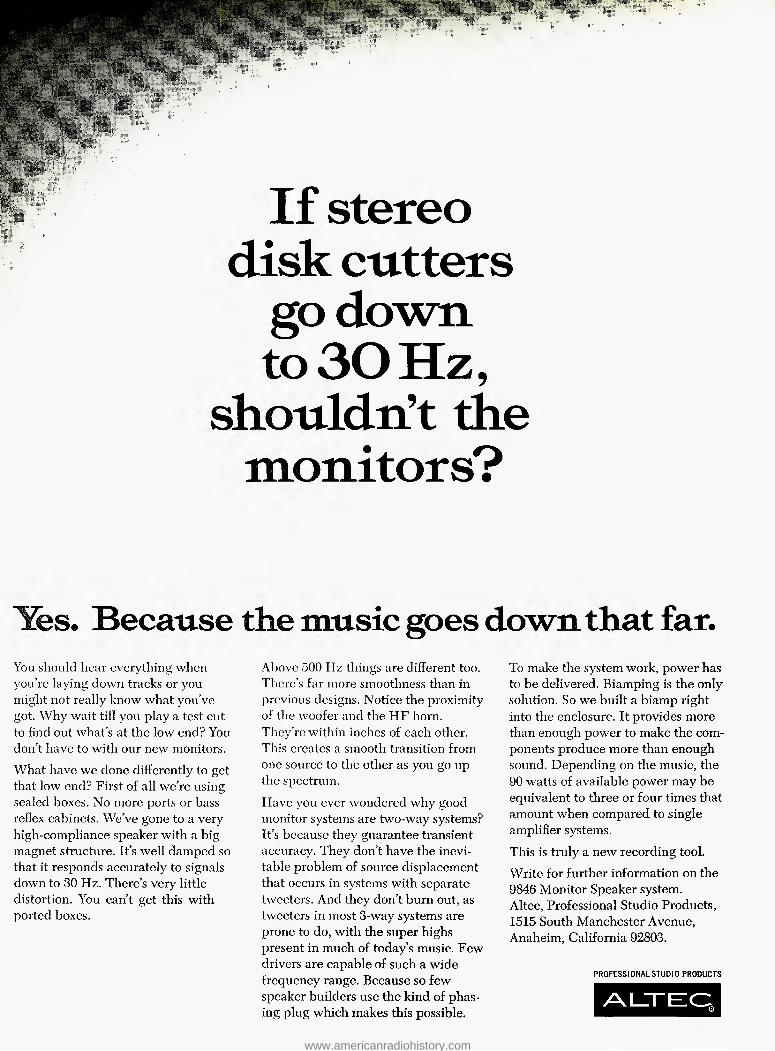
If stereo
disk cutters
go down
to30 Hz,
shouldn't the
monitors?
Yes. Because the music goes down that far.
You should hear everything when you're laying down tracks or you might not really know what you've got. Why wait till you play a test cut to find out what's at the low end? You don't have to with our new monitors.
What have we done differently to get that low end? First of all we're using sealed boxes. No more ports or bass reflex cabinets. We've gone to a very high-compliance speaker with a big magnet structure. It's well damped so that it responds accurately to signals down to 30 Hz. There's very little distortion. You can't get this with ported boxes.
Above 500 Hz things are different too. There's far more smoothness than in previous designs. Notice the proximity of the woofer and the HF horn. They're within inches of each other. This creates a smooth transition from one source to the other as you go up the spectrum.
Have yoxi ever wondered why good monitor systems are two-way systems? It's because they guarantee transient accuracy. They don't have the inevi- table problem of source displacement that occurs in systems with separate tweeters. And they don't bum out, as tweeters in most 3-way systems are prone to do, with the super highs present in much of today's music. Few drivers are capable of such a wide frequency range. Because so few speaker builders use the kind of phas- ing plug which makes this possible.
To make the system work, power has to be delivered. Biamping is the only solution. So we built a biamp right into the enclosure. It provides more than enough power to make the com- ponents produce more than enough sound. Depending on the music, the 90 watts of available power may be equivalent to three or four times that amount when compared to single amplifier systems.
This is truly a new recording tool.
Write for further information on the 9846 Monitor Speaker system. Altec, Professional Studio Products, 1515 South Manchester Avenue, Anaheim, California 92803.
PROFESSIONAL STUDIO PRODUCTS
ALXEEC:
www.americanradiohistory.com
DAVID E. BLACKMER
A Wide Dynamic Range
Noise-Reduction System
Noise in tape recording is examined and a system
for reduction that is now in use is described.
Tape recording has been one of the major sources of noise in professional studio systems .The al- most universal application of multitrack tech- niques has accentuated the problem. The widely-
used Dolby system gives just enough noise reduction to offset the 12 dB noise buildup inherent in sixteen-track recording. The continuing demand for improvement in quality delivered to the consumer makes further evolu- tion in noise-reduction systems mandatory.
Several forms ot noise reduction have been developed which selectively restrict the frequency response of the playback system alone. Signal components 40 or even 50 dB below program level form a vital part of perceived sounds. These are buried in the background noise and cannot be separated from it without extremely elaborate systems hence program quality is degraded. We have therefore restricted our interest specifically to those sys- tems capable of complementary coding and decoding over a wide dynamic range.
A number of possible techniques exist for signal cod- ing before recording and decoding on playback. The most practical appears to be the form which uses the signal itself to carry the requisite information for de- coding. Such systems are equivalent to compression be- fore recording and expansion on playback. Many of these have been used extensively. The Dolby A system is a four band compressor-expander. Several recording compa- nies have used 1:2 compression factor companders for tape masters. Oppenheim and Stockham at MIT's Lincoln Laboratory devised an ingenious linear decibel compressor- expander using logarithmic amplifiers. Burwen has de- scribed a 3:1 compression factor system using peak sig- nal detection capable of 110 dB range between peak sig- nal and background noise. And of course, long distance telephone circuits have been equipped with companders for more than 30 years.
The quality and usefulness of a noise-reduction system for professional studio aplications can be judged on dy-
jN namic range coverage, accuracy of dynamic tracking, o> especially on rapid rise transients, and ability to handle ^ the imperfections inherent in the tape recording process g- gracefully. W It was our objective in this work to develop a system di capable of recording the entire useful auditory dynamic ^ range with excellent transient tracking. It must operate ^ with existing recorders and be producable for a prac- xi tical price.
David E. Blackmer is president of DBX Inc., of Harvard, 5 Mass.
DESIGN EVOLUTION A linear decibel compressor-expander may be accom- plished in the manner shown in Figure 1. Voltage con- trolled amplifiers control the input and output gain. Input and output level sensors control gain with an appropriate control polarity to produce compression in section A and expansion in Section B. Such a system might seem prac- tical as a noise-reduction system as it can multiply the recorder dynamic range by the compression factor. A 60 dB recorder with a 2:1 factor system could yield a 120 dB signal-to-noise ratio. Unfortunately, the instantaneous background noise level varies with the signal envelope. The human ear can tune out a steady hiss to the point where the listener is only subliminally conscious of it. A varying noise envelope has a much higher auditory an- noyance factor. Consequently this system is quite un- satisfactory for critical applications although its per- formance looks outstanding on paper.
TAPE NOISE It is important to understand the behavior of the noise sources in tape recording. We are all familiar with the sound of the background noise in the absence of signal. It typically has the spectral distribution shown by the lower curve in Figure 2. When a signal is recorded the noise increases. The other curves show the resulting spectral distribution when a 180 Hz tone is recorded at various levels. Note that the noise in the entire spectrum is in- creased with increasing signal. The increase is greater near the tone frequency. The broadband noise increase is due to the increased number of magnetized domains passing by the playback gap. The increase near the tone is due to inhomogenity in magnetic particle distribution in the tape coating and to surface asperities which lift the tape away from the gap as they pass through. Both these mechanisms cause an amplitude modulation of the signal by random functions which of course results in noise sidebands. The upper curve shows the background noise accompanying a +10 dB record level corresponding to the recording level on program peaks. The entire high frequency noise spectrum has risen. Note that the instan- taneous signal-to-noise ratio of tape recording is nearly constant above —10 dB recording level. This causes an apparent increase in the high-frequency content of tape recorded signals.
With most audio signals, masking effects cover up noise effects within several octaves of the frequency band containing the dominant energy, but background hiss which is 50 dB under a strong low frequency signal can be plainly heard.
www.americanradiohistory.com

Figure 1. A linear compressor-expander system using voltage controlled amplifiers. 20 50 I00 500 IK 5K I0K 20K
FREQUENCY IN HERTZ
HIGH-FREQUENCY PRE-EMPHASIS
The high-frequency hiss changes accompanying signal envelope level changes may be rendered virtually in- audible with high-frequency pre-emphasis. If a 12 dB weighting is used from 400 Hz to 1600 Hz as shown in Figure 3, then the high-frequency hiss accompanying a strong low-frequency signal is reduced by nearly 12 dB. This will also cause a sharp increase in susceptibility to high-frequency self erasure which is already a problem without this pre-emphasis with many types of signals commonly recorded in contemporary music.
PRE-EMPHASIS OF LEVEL SENSOR SIGNAL This problem may be resolved with the use of high- frequency pre-emphasis before the level sensing circuit. Any desired frequency shaping function may be applied to such a compressor-expander system level sensor as long as both record and play level sensor pre-emphasis curves are identical. We have chosen a 20 dB pre-empha- sis starting at 1600 Hz which produces the sine-wave response curve shown in Figure 3. Note that this is the single frequency sine-wave response curve of the system. The complex wave weighting remains that shown in Figure 2 at all times.
TRANSIENT RESPONSE A system such as this is only useful if it has adequate transient response tracking properties. Peak responsive level sensors seem at first glance ideal. Unfortunately, peaks 24 dB above vu meter reading are common, espe- cially in mixdown. Tape recording levels are commonly run in a region where such peaks are flattened. This peak truncation is free from sudden slope changes, but serious tracking errors would occur between record and play level sensors. Equally obviously, average level sensors would be too slow. Furthermore, most tape recorders have considerable time delay dispersion (frequency de- pendant phase shift changes not giving constant time de- lay). Neither the peak nor the average value of a signal remains unchanged with non-constant time delay. The one function which is unchanged is the rms value of the signal. The rms value is the sum of the energy of all fre- quency components present without regard to their phase relationships. If there were a means to sum the squares of instantaneous signal levels, then the signal rms value could be determined. Fortunately recent advances in analog computation techniques have made this possible. The circuit shown in Figure 4 squares the signal by doubling the logarithm then taking the antilog. This squared signal is averaged and used to derive the control signal.
The final system design is shown in Figure 5. The in- put pre-emphasis network boosts the high-frequency con-
Figure 2. Noise in tape recording.
tent of the signal. The voltage-controlled amplifier con- trols signal gain in response to the output of the level sensor with a pre-emphasis network feeding the level sensors. The compression factor is set at 2:1. The unity gain point is set at +4 dBm at I kHz.
The decoder has an identical level sensing circuit which will therefore give the same control signal as that used in the input compressor. The control polarity to the vca is reverse. The over-all system gain remains unchanged as the two vca's give complementary gain changes. A de-emphasis network on the output restores frequency response.
SYSTEM PERFORMANCE
This noise-reduction system when used with a studio tape recorder has an equivalent "A" weighted background noise under —90 dBm without audible imperfections. A difference in apparent high-frequency response can be heard as the noise reduction system is alternately switched in and bypassed while recording and playing simultane- ously with a tape recorder, but carfeul comparison of the original signal with both recorded signals shows that the noise-reduced signal sounds like the original and that the cause of this difference was the increase of tape hiss with record level as shown in Figure 2.
There are other barely audible imperfections due to asperity noise with some types of very clear signals but these noise components lie in the same frequency region as the dominant signal energy band hence we must look to improvements in tape surfaces for their reduction re- gardless of the noise-reduction system used. Incidentally,
Figure 3. High-frequency hiss changes accompanying signal envelope level changes may be rendered virtually inaudible with high-frequency pre-emphasis.
+ 15
+10
+- 5
0
- 5
RE :or D- G -n ING
El X II :d -SINE WA /E F Sf 'C
20 50 100 500 IK 5K IGK 20K FREQUENCY IN HERTZ
Q. O" > c tp 'l C/) CD ■o
CO N>
Ol Ol
www.americanradiohistory.com

Figure 4. This circuit squares the signal by doubling the logarithm, then taking the antilog.
CODER DECODER
these components can be masked almost completely with a steady hiss. The required level of this "noise perfume" is about —65 dB. It is no coincidence that noise-reduc- tion systems which claim no audible effect have this resi- dual noise level present in the output.
The DBX noise-reduction system handles very well in studio use. No level matching is required for accurate transient response. The complete absence of audible back- ground noise requires some rethinking of recording tech- niques. Gain riding is unnecessary in all original session recording. There is more latitude for post equalization so that most equalization can be left for the mixdown ses- sion. Limiting and compression are only used where re-
Figure 5. The final system design.
quired for effect. A number of generations of re-recording may be used without excessive noise buildup.
The signal quality improvement due to this system can give the studio master tape recording a better sound and dynamic range than the best disc recording, thereby sig- nificantly improving the quality of audio delivered to the growing number of critical listeners. Only when it is gone do you realize how pervasive background noise has been in recorded sound. ■
A little.free book that can lead —-> -1 ventiires on a
the West Indies.
Cap'n Mike. Windjammer Cruises. P.O. Box 120, Dept. 000, Miami Beach, Florida 33139. Send me the little, free book! Name Address City State Zip..
We'll show you more of the West Indies than you'll ever see out of a hotel room
window. You'll set foot on Dominica, Montserrat, Guadaloupe, English
Antigua and French Martinique. You'll skindive, swim, snorkel, prowl
uninhabited beaches. You'll limbo, calypso and rock to a steel band. Take
a night watch or fall asleep under a star spangled sky. 10 days from $250.
It could make the best-seller list!
©Windjammer Cruises.
www.americanradiohistory.com

A friendly understanding.
A phrase that perfectly
describes the relationship between
Revox tape recorders and Beyer
microphones. One fine piece of
equipment uniquely
complementing another.
Wherever you go, you'll find
these two thoroughgoing
professionals working together.
On location and in the most
demanding studio situations.
Both Revox and Beyer are
expressions of the same European
dedication to meticulous
craftsmanship and superior
technology.
For example, take the new
Revox A77 Mk III. It's the
successor to the critically ac-
claimed Revox A77, the machine
that moved Stereo Review to
comment, "We have never seen a
recorder that could match the
performance of the Revox All
in all respects, and very few that
even come close!'
Or take the new Beyer M500
microphone. You've never used
anything quite like it. It combines
the sharp attack of a condenser
and the sturdy reliability of a
moving coil with the undupli-
catable warmth of a ribbon.
And Beyer makes a number of
other microphones to satisfy
virtually any broadcasting or
recording requirement.
Together or separately, these
sophisticated instruments provide
the ideal solution to the problem
of versatile, high quality, low
cost recording.
Your nearest Revox-Beyer
dealer will be pleased to
demonstrate any of these fine
products for you.
After that, you can arrive at
your own friendly understanding.
For additional information and
complete technical specifications,
write: Revox Corporation,
155 Michael Drive, Syosset,
New York 11791.
Q. C7
C/) (D •D
CD -vl ro
California: 3637 Cahuenga Blvd. West, Hollywood 90068. Canada: Tri-Tel Associates, Ltd., Montreal. London: Lamb House, Church Street, Chiswick, W4 2PB
Circle 47 on Reader Service Card
j ADDRESS.
afeggpsass i CITY_ STATE. _Z1P_
CHICAGO • LOS ANGELES • TORONTO □ DIST. IN MILAN HAMBURG • PARIS • LONDON • BEIRUT
Circle 23 on Reader Service Card
tn
01 CD
www.americanradiohistory.com
Wieite—
look who's
You may have heard it already—or you may not have — but more and more recording artists, more and more recording labels, and more and more engi- neers and producers are using Sansui's QS four- channel technique to encode their records in the four-channel mode. The list, growing from week to week, is quite impressive. But more important than the list itself is the fact that all these independent artists and companies have conducted extensive testing and actual use procedures before they made up their minds. What speaks for Sansui's QS System is not the pressure of a major software company nor exaggerated statements and promises; it's simply the performance. Whether it is such an outstanding artist as Carole King or Joan Baez; or perhaps eminent musicians and producers like Enoch Light or Dick Schory add to the list such a beloved figure as B. B. King — they all are going Sansui's QS way because they think it is the best way. Some of these artists have actually produced with other matrix four-channel encoding methods, but have found that the most satisfactory results, in terms of the freedom of the producer and the artistic results, are in the one and only balanced and symmetrical system —that is, Sansui's QS method.
www.americanradiohistory.com
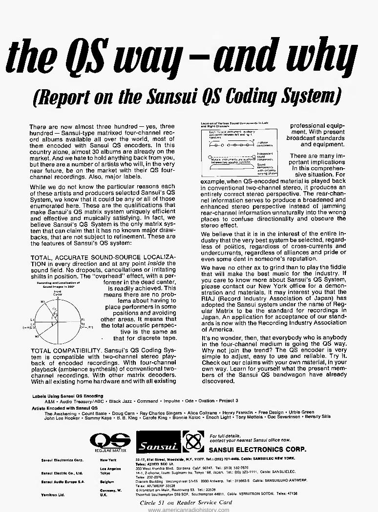
the QS way-and why
(Report on the Sansui QS Coding System)
There are now almost three hundred — yes, three hundred — Sansui-type matrixed four-channel rec- ord albums available all over the world, most of them encoded with Sansui QS encoders, in this country alone, almost 30 albums are already on the market. And we hate to hold anything back from you, but there are a number of artists who will, in the very near future, be on the market with their QS four- channel recordings. Also, major labels.
While we do not know the particular reasons each of these artists and producers selected Sansui's QS System, we know that it could be any or all of those enumerated here. These are the qualifications that make Sansui's QS matrix system uniquely efficient and effective and musically satisfying. In fact, we believe Sansui's QS System is the only matrix sys- tem that can claim that it has no known major draw- backs, that are not subject to refinement. These are the features of Sansui's QS system;
TOTAL, ACCURATE SQUND-SQURCE LQCALIZA- TION in every direction and at any point inside the sound field. No dropouts, cancellations or irritating shifts in position. The "overhead" effect, with a per-
former in the dead center, is readily achieved. This
means there are no prob- lems about having to
place performers in some positions and avoiding
other areas. It means that the total acoustic perspec-
tive is the same as that for discrete tape.
TOTAL COMPATIBILITY. Sansui's QS Coding Sys- tem is compatible with two-channel stereo play- back of encoded recordings. With four-channel playback (ambience synthesis) of conventional two- channel recordings. With other matrix decoders. With all existing home hardware and with all existing
professional equip- ment. With present
broadcast standards and equipment.
There are many im- portant implications
in this comprehen- sive situation. For
example,when OS-encoded material is played back in conventional two-channel stereo, it produces an entirely correct stereo perspective. The rear-chan- nel information serves to produce a broadened and enhanced stereo perspective instead of jamming rear-channel information unnaturally into the wrong places to confuse directionality and obscure the stereo effect. We believe that it is in the interest of the entire in- dustry that the very best system be selected, regard- less of politics, regardless of cross-currents and undercurrents, regardless of alliances and pride or even some dent in someone's reputation. We have no other ax to grind than to play the fiddle that will make the best music for the industry. If you care to know more about Sansui's OS System, please contact our New York office for a demon- stration and materials. It may interest you that the RIAJ (Record Industry Association of Japan) has adopted the Sansui system under the name of Reg- ular Matrix to be the standard for recordings in Japan. An application for acceptance of our stand- ards is now with the Recording Industry Association of America. It's no wonder, then, that everybody who is anybody in the four-channel medium is going the QS way. Why not join the trend? The QS encoder is very simple to adjust, easy to use and reliable. Try it. Check out our claims with your own material, in your own way. Learn for yourself what the present mem- bers of the Sansui QS bandwagon have already discovered.
Rscordlng and Localization of Sound Imaga* In 360*
Front Center 0
Location of Variou* Sound Components In Left and Right Channel* Each musical instrument is clearly positioned between left and right speakers.
Independent Q O sound Musical instruments are scattered components between two speaker systems. ^ n. Sound / J components with randomly varying phases
Labels Using Sansui QS Encoding A&M • Audio Treasury/ABC • Black Jazz • Command • Impulse • Ode • Ovation • Project 3
Artists Encoded with Sansui QS The Awakening • Count Basie • Doug Cam • Ray Charles Singers • Alice Coltrane • Henry Franklin • Free Design • Urbie Green John Lee Hooker • Sammy Kaye • B. B. King • Carole King • Bonnie Koloc • Enoch Light • Tony Mottola • Doc Severmsen • Beverly Sills
Sansui Electronics Corp.
Sansui Electric Co., Ltd. Sansui Audio Europe S.A.
Vernitron Ltd.
REGULAR MATRIX
Los Angeles Tokyo Belgium Germany, W. U.K.
ScutsuL
For full details. contact your nearest Sansui office now.
krSil SANSUI ELECTRONICS CORP. 32-17, 61st Street, Woodside, N.Y. 11377. Tel.: (212) 721-4408. Cable: SANSUILEC NEW YORK. Telex: 422633 SEC Ul. 333 West Alondra Blvd. Gardena. Calif 90247. Tel : (213) 532-7670 14-1. 2-chome. Izumi Suginami-ku. Tokyo 168, Japan. Tel : (03) 323-1111. Cable: SANSUIELEC. Telex: 232-2076 Diacem Building Vestingstraat 53-55. 2000 Antwerp, Tel.: 315663-5. Cable: SANSUIEURO ANTWERP. Telex: ANTWERP 33538 6 Frankfurt am Main. Reuterweg 93. Tel.: 33538 Thornhill Southampton S09 5QF. Southampton 44811. Cable VERNITRON SOTON. Telex: 47138.
Circle 51 on Reader Service Card www.americanradiohistory.com
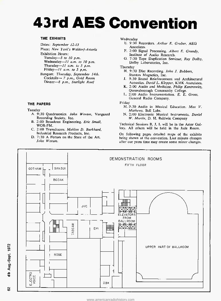
43 rd AES Convention
THE EXHIBITS
Dates; September 12-15 Place: New York's Waldorf-Astoria Exhibition Hours:
Tuesday—5 to 10 p.m. Wednesday—11 a.m. to 10 p.m. Thursday—11 a.m. to 5 p.m. Friday—II a.m. to 5 p.m.
Banquet: Thursday, September 14th. Cocktails—- 7 p.m., Gold Room Dinner—8 p.m., Starlight Roof
Woram, Vanguard
THE PAPERS
Tuesday A. 9:30 Quadrasonics. John
Recording Society, Inc. B. 2:00 Broadcast Engineering. Eric Small,
WOR-FM. C. 2:00 Transducers. Mahlon D. Burkhard,
Industrial Research Products, Inc. D. 7:30 A Forum on the State of the Art.
John Woram.
Wednesday E. 9:30 Recorders. Arthur E. Gruber, AEG
Associates F. 2:00 Signal Processing. Albert E. Grundy,
Institute of Audio Research. G. 7:30 Tape Duplication Seminar, Ray Dolby,
Dolby Laboratories, Inc. Thursday
H. 9:30 Disc Recording. John J. Bubbers, Stanton Magnetics, Inc.
J. 9:30 Sound Reinforcement and Architectural Acoustics. David L. Klepper, KMK Associates.
K. 2:00 Audio and Medicine. Philip Kantrowitz, Queensborough Community College.
L. 2:00 Audio Instrumentation. E. E. Gross, General Radio Company.
Friday M. 9:30 Audio in Musical Education. Max V.
Mathews, Bell Labs. N. 2:00 Electronic Musical Instruments. Daniel
W. Martin, D. H. Baldwin Company
Technical Sessions B, J, L will be in the Astor Gal- lery. All others will be held in the Jade Room.
On following pages detailed maps of the exhibits being shown at the convention. Last minute changes after our press time may create some minor changes.
eg o
o. a> CO
A ■a
CNJ CD
www.americanradiohistory.com

□ □ □ □ □
JADE ROOM TECHNICAL SESSIONS
O h-
> o o >-
— LU ^ ^ cr o h- co < Lj_ or o Q
ID
cr LU UJ
< —
o o CO
OJ O — ? cr Ld
cr o o
Lu
x
r*
X X
X
X o X UJ cr ^ I X
=] lu cu no cu nz:
ASTOR GALLERY
TECHNICAL SESSIONS
□ □ czi □ czi cd
——1 cr i c \ / a xrid c 1— EXHIBITOR
SERVICE DESK ELEVATORS
FROM LOBBY
t a t ^ t ^ t1=11
CZI CZ1 □ □ cz: cn-
>D
'n
XL
AMPEX 1
AUDI- TRON ICS
o 1 < DOLBY
1 1
ELECTRC 1
SOUND 1
ti=lli=i|c=itral rat i= 5 or o <r (r
$ o a:
O Ll) o: co o
^ ^ ^ ^ ^ ^ -S-
HARVEY < o
RE VOX
_AUDIO - TECHNIQUES
o co u UJ ^ 00 < co uj- O o I- o 3 cr < Q-
o 2- UJ O H- Z 2 o LU CD Q. <
< — o-
SCULLY WESTLAKE PRATT
COUJ Z)Q Of!
Q -0_
O Q
rO
X V
d 1 ^ L
goi rs
X V
UJ - Q P 'Z. UJ >
J u □ u
/ \
X
/ \
X fl
kr
Q_ <
Lj
□ □ □
i
□
www.americanradiohistory.com

As a service to our readers we are pleased to ofler books from prominent technical publishers. All prices listed are the publishers' net. Shipping charges are Included. To order use the coupon at the bottom ol the page. Indicate quantity on the special instructions line
II more than one copy of a title is wanted. Pull payment must accompany your order. We cannot ship c.o.d. Checks or money orders should be made payable to Sagamore Publishing Company, Inc. Because of the time required to process orders, allow several weeks for the receipt of books.
20. The Audio Cyclopedia (2nd ed.). Dr. Howard M. Tremaine. New and updated, here is the complete audio reference li- brary in a single volume. It provides the most comprehensive information on every aspect of the audio art. This new edition includes the latest audio developments in- cluding the most recent solid-state systems and integrated circuits. It covers all sub- jects in the fields of acoustics, recording, and reproduction with more than 3400 re- lated topics. Each topic can be instantly located by a unique index and reference system. More than 1600 illustrations and schematics help make complicated topics masterpieces of clarity. 1760 pages; &V2 x 9% hardbound. $29.95
1. The Technique of the Sound Studio. Alec Nisbett. This is a handbook on radio and recording techniques, but the princi- ples described are equally applicable to film and television sound. 264 pages; 60 diagrams; glossary; indexed; 5'/2 x S'/a; clothbound. $14.50
7. Acoustical Tests and Measurements. Don Davis, Provides solid understanding of the entire subject of acoustical measure- ments; based on actual field test work, using commercial equipment. 192 pages; 5V2 x SVs; hardbound. $6.95
8. Handbook of Electronic Tables & Formulas, (3rd edition). A one-stop source for all charts, tables, formulas, laws, sym- bols, and standards used in electronics. In- cludes an 8-page, full-color fold-out chart showing latest FCC allocations for the en- tire frequency spectrum. 232 pages; SVz x 8V2; hardbound. $5.50
Sagamore Publishing Company, Inc. 980 Old Country Road, Plainview, N.Y. 11803
Please send me the books I have circled below. My full remittance in the amount of 5 is enclosed. N.Y. State resi- dents add 7% sales tax. 1 2 3 4 5 6 7 8 9 10 11
12 13 14 15 16 17 18 19 20 21 22 23 24 25 26 27 28 29 30 31 32 33 34 35 36 37 38 39 40 CM f-- O) Name_
CL 03 OT 1 d) < <0 ■a
Address.
City
State Special Instructions
Zip-
Canada and foreign: Add $1.00 per book
24. Basic Electronic Instrument Handbook. Edited by Clyde F. Coombs, Jr. Hewlett- Packard Co. A basic reference background for all instruments. Offers saving in time and effort by having complete information in one volume on how to get the most bene- fit from available devices, how to buy the best instrument for specific needs. Reduces chances of costly errors. Ideal reference book, it is an excellent source for the be- ginner, technician, the non-electrical en- gineering man, or general non-engineering scientific and technical personnel. 800 pages. Hardbound. $19.50
25. Operational Amplifiers-Design and Applications. Burr-Brown Research Corp. A comprehensive new work devoted en- tirely to every aspect of selection, use, and design of op amps—from basic theory to specific applications. Circuit design tech- niques including i.e. op amps. Applica- tions cover linear and non-linear circuits, A/D conversion techniques, active filters, signal generation, modulation and de- modulation. Complete test circuits and methods. 474 pages. $15.00
26. The Design of Digital Systems. John B. Peatman. Textbook for students desiring to develop a creative approach design capa- bility through digital systems approach. Answers these question: Under what cir- cumstances it is desirable to implement a system digitally? What are some of the components available for implementing the system? How do we go about design- ing it? 448 pages. $15.50
31. Solid-State Electronics. Hibberd. A Basic Course for Engineers and Techni- cians. An extremely practical reference book for anyone who wants to acquire a good but general understanding of semi- conductor principles. Features questions and answers, problems to solve. 1968. 169 pp. $9.95
32. Circuit Design for Audio, AM/FM, and TV. Texas Instruments. Texas Instruments Electronics Series. Discusses the latest ad- vances in design and application which represent the results of several years re- search and development by Tl communica- tions applications engineers. Emphasizes time- and cost-saving procedures. 1967. 352 pp. $14.50
35. An Alphabetical Guide to Motion Picture, Television, and Videotape Produc- tions. Levitan. This all-inclusive, authorita- tive, and profusely illustrated encyclopedia is a practical source of information about techniques of all kinds used for making and processing film and TV presentations. Gives full technical information on mate- rials and equipment, processes and tech- niques, lighting, color balance, special effects, animation procedures, lenses and filters, high-speed photography, etc: 1970. 480 pp. $24.50
40. Radio Transmitters. Gray and Graham. Provides, in a logical, easy-to-understand manner, a working knowledge of radio transmitters for quick solution of problems in operation and maintenance. 1961. 462 PP $16.00
23. Wide Screen Cinema & Stereophonic Sound. M.Z. Wystozky. First published in USSR in 1965 this excellent English trans- lation covers wide gauge films, panoramic films, circular panoramic cinematography; technical fundamentals of stero sound re- cording for film, as well as details of the Soviet systems now in use. 284 paqes.
$15.00
33. Noise Reduction. Beranek. Designed for the engineer with no special training in acoustics, this practical text on noise control treats the nature of sound and its measurement, fundamentals of noise con- trol, criteria, and case histories. Covers advanced topics in the field. 1960. 752 pp.
$19.50
27. Noise & Vibration Control. Edit, by Leo L. Beranek. Practical design and reg- ulatory information; formulas, choice of materials and structures, city codes and hearing protection; indispensable for de- sign engineers, public officials who prepare regulations for noise control, safety and environmental engineers involved in noise and vibration controls. Covers data analysis, transmission of sound, psychophysiological design criteria, hearing damage risk, etc: Wealth of detail, comprehensive index and concise appendices. 650 pages. $29.50
28. Environmental Acoustics. Leslie L. Doelle. Applied acoustics for those in envi- ronmental noise control who lack spe- cialized acoustical training. Basic informa- tion in comprehensible and practical form for solving straightforward problems. Ex- plains fundamental concepts; pure theory minimized. Practical applications stressed, acoustical properties of materials and con- struction listed, actual installations with photos and drawings. Appendixes illustrate details of 53 wall types and 32 floor plans and other useful data. 246 pgs. $18.50
21. Acoustics—Room Design and Noise Control. Michael Rettinger. 1968. The enormous problems and hazards presented by noise are dealt within an orderly and practical manner. With many charts, graphs, and practical examples, the text covers the physics of sound, room acous- tics, and design, noise and noise reduc- tion. 392 pages. $17.50
22. Acoustics of Studios and Auditoria. V.S. Mankovsky. Basic theory plus a mass of design data covers the field with special reference to studios and places of public performance. For acoustical designers and specialists in sound transmission in cinema and broadcasting. Features exhaustive treatment of studio acoustics by the sta- tistical, geometric and wave methods in parallel. 416 pgs. $15.00
www.americanradiohistory.com

CLASSIFIED
FOR SALE
NEW YORK'S LEADING supplier of pro- fessional recording equipment and hi-fi stereo components. All major brands in stock. Call for quote—sales—service —leasing—trade-ins. Martin Audio, 320 West 46th Street, New York, N.Y. 10036. Telephone: (212) 265-6470.
AMERICA'S LARGEST SELECTION of new and used broadcast and recording equipment! Latest bulletins available. The Maze Corporation, P.O. Box 6636, Birmingham, Ala. 35210.
WHATEVER YOUR EQUIPMENT NEEDS —new or used—check us first. Trade your used equipment for new. Write for our complete listings. Broadcast Equip- ment & Supply Co., Box 3141, Bristol, Tenn. 37620.
SOLID-STATE AUDIO MODULES. Con- sole kits, power amplifier kits, power supplies. Octal plug-ins—mic, eq, line, disc, tape play, tape record, amplifiers. Audio and tape bias oscillators. Over 50 audio products, send for free catalog and applications, Opamp Labs. Inc., 172 So. Alta Vista Blvd., los Angeles, Ca. 90036. (213) 934-3556.
HAECO announces complete repair ser- vice and overhaul for all Westrex cut- terheads. Conversions of 3D-II and old- er models to higher performance stand- ards and reliability. Helium cooling systems and hi-temp coils can protect your investment. Repair insurance pro- gram available. Rapid service. Lower cost. HAECO, 14110 Aetna, Van Nuys, California 91401.
IN THE NORTHEAST it's Audiotechniques for STANDARD TAPE LABORATORY test tapes. We think they're the most depend- able, accurate reference tapes available. Call Ham Brosious or Bob Berliner and find out why. Audiotechniques, 121 Hamil- ton Avenue, Stamford, Conn. 06902. Phone (203) 359-2312.
ALTEC 1567A MIXERS, transformers in/ out—$225,00; 31 IB horns—$75.00; 291- 16 drivers—$110.00; 2036 horns— $110.00; 9473A compressor—$300,00. Crown D40—$175.00; 30-30—$150.00; DC-300—$450,00, C/M x-over—$100.00; Shure M-63—$65.00. Nightshade & Dark Productions, P.O. Box 511, Scarsdale, N.Y. 10583. (914) 703-8593 or 703- 3959.
FAIRCHILD LUMITEN PANPOTS (8) with rack card file; CBS Labs 421 stereo Vol- umax peak limiter. Studio EAST, 832 N. Van Buren, Milwaukee, Wisconsin 53202. (414) 271-0404.
LANGEV1N AM4A CONSOLE, 8 input, 2 output, wired for 14 input, 4 output. Mint condition, less than eighteen months old. Believe it or not, equipment was in- stalled in a bedroom and received only minor use and tender loving care. Went for just under $7000 new. Best offer takes it home. Write or call Alan Kubi- cka, P.O. Box 135 Roselle, Illinois 60172. (312) 529-1001.
AUDIO RESEARCH, Otari, Transtatic In- finity, Dayton Wright, I.M.F., B & W, Quad, EPI, Braun, B & O, Citation, Sin- clair, Phase Linear. Transcendental Audio, 1214 Walden, Buffalo, N.Y. 14211. (716) 897-3984.
SPECIAL—NEW FIDELIPAC NAB cart- ridges, 10 sees to 6 minutes. Only $1.25 each. Minimum quantity 50 carts. Specify lengths when ordering. Gately Electron- ics, 57 W. Hillcrest Avenue, Havertown, Pa. 19083.
SCULLY TAPE RECORDERS—one to twenty-four track and model 270 auto players, many models in stock for im- mediate delivery. SCULLY LATHES— Previously owned and rebuilt. Variable or automatic pitch. Complete cutting systems with Westrex heads. MIXING CONSOLES—Custom designed using Weigand Audio Lab modules. From $7,000.00. Weigand Audio Laboratories, R,D. 3, Middleburg, Pa. 17842. Phone
(717) 837-1444.
HUM
CATV—MATV PRODUCTS • CONNECTORS • WALLPLATES • SPLITTERS • AMPLIFIERS
AVA electronics corp. 416 LONG LANE, UPPER DARBY PA 19082 215—MA 6 9I0C
FM TUNER/RECEIVER alignment. Free checkout for distortion, frequency re- sponse, separation (see June-July 1970 issues of Audio). Complete FM tuner alignment $20 plus parts. One year guarantee, FOB A. L. Boynton, 369 Aklan Ct., San Jose, Ca. 95119.
AMPEX 351-2-X. Especially-built high- performance machine with many extras. Includes portable case plus walnut ver- ticle cabinet, spare motor, etc.—$1400. Also Altec 1567A mixer, G-R 650A bridge, MDC 300 'scope and two Schoeps CMT46 mics. Francis Daniel, 201 West 89th St., New York, N.Y. 10024. (212) 874-0590.
IN THE NORTHEAST it's Audiotech- niques for MCI 8-16-24 track recorders. The performance is superb, the price is right and the delivery is fast! What else do you want? You're right . . . service! That's Bob Berliner's job, and there's none better. Audiotechniques, 121 Hamilton Avenue, Stamford, Conn. 06902. (203) 395-2312.
SAVE MONEY—Top quality low noise tape. Vt." x 2500 ft. polyester on NAB reel—$8.50. 1" x 2500 ft. polyester on hubs—$11.50. 2" x 3600 ft. on prec. reel—$32.00. Also Scotch 150, Ampex 600, Reeves 1 mil Mylar Vi" x 3600 ft. on fiber glass reel, no boxes, in bulk excellent duplicator stock—$2.00 each in lots of 100. Quantity discount. Full re- turn privilege. FOB N.Y.C. warehouse. Selex Corporation, 61 Grove St., New York, N.Y. 10014. (212) 242-8003.
ASSUME PAYMENTS. Quad-Eight 1682, 10 in 8 out. AG-440-B. Write for details c/o P.O. Box 40603, Nashville, Tenn. 37204.
ONE STOP FOR ALL your professional audio requirements. Botton line ori- ented. F.T.C. Brewer Company, P.O. Box 8057, Pensacola, Florida 32505.
SAVE ON YOUR STYLUS COSTS! World's finest recording styli for all Westrex 3D models and HAECO SC-2. $12.80 unwired, $13.80 wired. Quantity purchases at additional savings. Satis- faction guaranteed. Send check or money order with your order to HAECO, 14110 Aetna St. Van Nuys, Ca. 91401.
ELECTRODYNE CONSOLE, 12 in/8 out, custom walnut with production area. Two-channel cue system with Crown D-40 amplifier. Marantz monitor amps. Make offer. Two nuvistor U-47's with power supplies, good condition—$225.00 each. Bob Schultz, Micside Inc., 2541 Nicollet Avenue, Minneapolis, Minn. 55404. (612) 827-5441.
FOR SALE; Established sound contract- ing company. Franchises on major lines with excellent acceptance ol equipment and personnel by area architects and en- gineers. This is the dominant company in the area doing the major share of work in hospital/nursing home, school- intercom and high-quality sound-rein- forcement fields. Sale includes company owned building and vehicles. Buyer must be acceptable to franchising manu- facturers, must be technically capable, and financially responsible. Write Box 9-A, db Magazine, 980 Old Country Road, Plainview, N.Y. 1 1803.
EMPLOYMENT
SAN DIEGO COUNTY, 4255 miles of "Heaven on Earth" Swim, sail, 66 golf courses, Sea World SD Zoo, major league sports, U.S. 12th largest city, mean temperature 66°. Wanted sales- men experienced in sound, l/C, matv, cctv, security systems—design and sales. Work in above environment. Product lines Altec, McMartin, Webster, Univer- sity, B-T, GBC, Javlin. Share profits! Resume to S. G. Barnes, Communica- tions Co., Inc., 3490 Noell St., San Diego, Ca. 921 10.
www.americanradiohistory.com
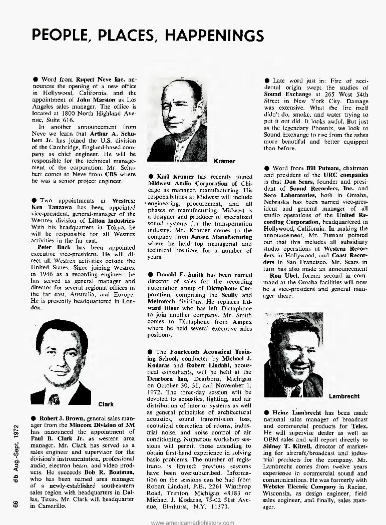
PEOPLE, PLACES, HAPPENINGS
# Word from Rupert Neve Inc. an- nounces the opening of a new office in Hollywood, California, and the appointment of John Marston as Los Angeles sales manager. The office is located at 1800 North Highland Ave- nue, Suite 616.
In another announcement from Neve we learn that Arthur A. Schu- bert Jr. has joined the U.S. division of the Cambridge, England-based com- pany as chief engineer. He will be responsible for the technical manage- ment of the corporation. Mr. Schu- bert comes to Neve from CBS where he was a senior project engineer,
9 Two appointments at Westrex: Ken Tanzawa has been appointed vice-president, general-manager of the Westrex division of Litton Industries. With his headquarters in Tokyo, he will be responsible for all Westrex activities in the far east.
Peter Buck has been appointed executive vice-president. He will di- rect all Westrex activities octside the United States, Since joining Westrex in 1946 as a recording engineer, he has served as general manager and director for several regional offices in the far east, Australia, and Europe. He is presently headquartered in Lon- don.
# Robert J. Brown, general sales man- ager from the Mincom Division of 3M has announced the appointment of Paul B. Clark Jr. as western area manager. Mr. Clark has served as a sales engineer and supervisor for the division's instrumentation, professional audio, electron beam, and video prod- ucts. He succeeds Bob R. Boatman, who has been named area manager of a newly-established southeastern sales region with headquarters in Dal- las, Texas. Mr. Clark will headquarter in Camarillo.
9 Karl Kramer has recently joined Midwest Audio Corporation of Chi- cago as manager, manufacturing. His responsibilities at Midwest will include
■ engineering, procurement, and all phases of manufacturing. Midwest is a designer and producer of specialized sound systems for the transportation industry. Mr. Kramer comes to the company from Jensen Manufacturing where he held top managerial and technical positions for a number of years.
9 Donald F. Smith has been named director of sales for the recording automation group of Dictaphone Cor- poration, comprising the Scully and Metrotech divisions. He replaces Ed- ward Ittner who has left Dictaphone to join another company. Mr. Smith comes to Dictaphone from Ampex where he held several executive sales positions.
# The Fourteenth Acoustical Train- ing School, conducted by Michael J. Kodaras and Robert Lindahl, acous- tical consultants, will be held at the Dearborn Inn, Dearborn, Michigan on October 30, 31, and November 1, 1972. The three-day session will be devoted to acoustics, lighting, and air distribution of interior systems as well as general principles of architectural acoustics, sound transmission loss, acoustical correction of rooms, indus- trial noise, and noise control of air conditioning. Numerous workshop ses- sions will permit those attending to obtain first-hand experience in solving basic problems. The number of regis- trants is limited; previous sessions have been oversubscribed. Informa- tion on the sessions can be had from Robert Lindahl, P.E., 2261 Winthrop Road, Trenton, Michigan 48183 or Michael J. Kodaras, 75-02 51st Ave- nue, Elmhurst, N.Y. 11373.
9 Late word just in: Fire of acci- dental origin swept the studios of Sound Exchange at 265 West 54th Street in New York City. Damage was extensive. What the fire itself didn't do, smoke, and water trying to put it out did. It looks awful. But just as the legendary Phoenix, we look to Sound Exchange to rise from the ashes more beautiful and better equipped than before.
• Word from Bill Putnam, chairman and president of the URC companies is that Don Sears, founder and presi- dent of Sound Recorders, Inc. and Seco Laboratories, both in Omaha, Nebraska has been named vice-pres- ident and general manager of all studio operations of the United Re- cording Corporation, headquartered in Hollywood, California. In making the announcement, Mr. Putnam pointed out that this includes all subsidiary studio operations at Western Recor- ders in Hollywood, and Coast Recor- ders in San Francisco. Mr, Sears in turn has also made an announcement —Ron Ubel, former second in com- mand at the Omaha facilities will now be a vice-president and general man- ager there.
Lambrecht
# Heinz Lambrecht has been made national sales manager of broadcast and commercial products for Telex. He will supervise dealer as well as OEM sales and will report directly to Sidney T. Kitrell, director of market- ing for aircraft/broadcast and indus- trial products for the company. Mr. Lambrecht comes from twelve years experience in commercial sound and communications. He was formerly with Webster Electric Company in Racine, Wisconsin, as design engineer, field sales engineer, and finally, sales man- ager.
www.americanradiohistory.com

TeleSessions
exclusively for [db| readers
How many times have you read an unusually stimulating article in db and wished you could trade ideas with others involved in that area? (People who share your problems and speak your language, who are full of surprising insights and new ideas.)
Although group discussions like this happen at conferences, and at chance meetings, our read- ers have been telling us they want it to happen more often and more conveniently. THE ELECTRONIC MEETING Now, without leaving your desk, you can have this kind of valuable, informal discussion. With- out the time and expense of travel, either. Group telephone conferences are held in connection with selected db articles—and we keep each group small. For articles that generate tremen- dous TeleSession* interest, we'll schedule as many separate small group sessions as required.
So readers most interested in each article can dial into an hour-long, freewheeling discussion and build on each other's ideas. TeleSession Company provides the unique telephone con- ference system that repeals geography. Our edi- tors pick the topics and invite authors or guest experts—whenever appropriate. A SURPRISING EXPERIENCE You'll find this specially engineered conference system and the group dynamics different from any "conference call" you may haveexperienced. You dial in over ordinary phone lines from any- where in the country you happen to be at ses- sion time. You're greeted by a session host who introduces everyone and gets things started. Everyone on the line can ask questions, explore ideas (it's amazing how one new idea leads to another), or just listen.
You'll find, even in your first few minutes, that db TeleSessions are more interactive and informal than face-to-face discussions. You always know who's talking, because participants say their first names. You drop formalities and simply chime in whenever you have a comment. Yet there are surprisingly few interruptions.
The result is a stimulating and orderly discus- sion. We've discovered that the participants are willing to reveal the best of their knowledge and ask questions when they don't know something. So what you get is a chain reaction of ideas. One person's knowledge complements everyone
else's—though each person forms his own con- clusions. Complete strangers end up talking as though they've known each other for years—and wanting to call on each other's expertise again.
So far, there've been over 700 TeleSessions.
HOW TO RESERVE YOUR TELESESSION "SEAT" Whenever you find a db article especially in- triguing that is marked for TeleSession discus- sion, we hope you will accept our invitation to participate with others who feel the same way. Simply fill out the reservation card and mention the topic for which you wish to reserve a "seat". We'll promptly reserve a line for you and advise you of your group's scheduled date and time. (If the time we send you conflicts with your schedule you may call 212/725-2525 and we'll immediately give you an alternate.)
Be sure to mark the scheduled meeting hour we send you in your appointment book; then when your session time arrives simply place a station-to-station call from wherever you are that day to 212/725-2525. Your session host will greet you and then after a few informal introductions you'll find yourself in one of the most productive meetings you've ever experienced. Wherever you are that day, you can fit the Tele Session hour into whatever you're doing. There's no time lost, no travel or lodging expense.
THE COST We think the fresh viewpoints you share in the first session will prove this to be the most cost- effective form of consulting you ever experi- enced. It's just thirty dollars for each Tele- Session, plus the cost of your simple station-to- station phone call. You may cancel up to five days before the session or have someone else take your "seat." If for any reason your db TeleSession isn't everything we've said it is, merely state the reason for your disappoint- ment on the invoice, return it and owe nothing. A MAGAZINE WITH AN INTERACTIVE FEEDBACK SYSTEM A provocative article. A small interdisciplinary group of professionals like you. A uniquely stim- ulating and convenient meeting environment. You owe it to yourself to give it a try. We look forward to welcoming you. Pick one of the ar- ticles marked for TeleSession and send in the attached card.
db TeleSessions 980 Old Country Rd. Plalnvlew, N.Y. 11803 212/725-2525
Please reserve my "seat" in the first available TeleSession group
on the topic:
Name
Company .
Title
Address.
City / State_ -Zip. . Phone J_
CD Check enclosed for $30.00. n Bill (me) (company)
Signed-
www.americanradiohistory.com

NEW Model RE10 $166.00 shown on Model 421 desk stand $20.00. Model RE15 $283.00 shown with Model 307 suspension mount $37.00. NEW Model RE11 $177.50, shown with Model 311 snap-out stand adapter $7.00. NEW Model RE16 $294.50, shown on Model 421 desk stand $20.00. List prices shown. Normal trade discounts apply.
Freedom of choice!
Professional sound has entered a KsU new era. It started with the Electro- Voice Model RE15. And now there are four E-V dynamic cardioid microphones that share its distinctive advantages — with some unique benefits of their own.
Unaffected by Distance... Angle Basic to all of these microphones is
Exclusive Electro-Voice Continuously Variable-D* construction. Now it offers something you've never heard before with any microphone: no matter what you do, microphone response never varies!
Whether performers almost swallow the microphone, wander far off-mike ... or even move around to the back... you'll still get the same smooth response. Only the level changes.
Once you set equalization it remains constant. You have full assurance that tonal balance won't change between the dress rehearsal and the final perfor- mance, no matter what the talent does.
Improved Cardioid Pattern Only acoustics and noise can limit
you. Yet even here these new E-V micro- phones gain an advantage from the super-cardioid pattern that provides better sound control than ordinary car- dioids. With maximum rejection 150° off axis, it is easier to eliminate unwanted sound while maintaining normal stand or boom microphone positions. There's also an integral bass-tilt circuit to cut rumble below 100 Hz. when needed.
Now Select from Four Models In addition to the original RE15, we've
added the RE16. The same fine micro- phone with an external "pop" filter to solve the problems of ultra-close miking.
The new RE 10 is the economy version of the RE15. The same concept and quality, but for slightly less rigid re- quirements. And the RE11 is the lower cost twin to the RE 16.
These four great cardioid microphones give you new freedom to head off sound problems before they start. Your E-V microphone headquarters has them waiting. Choose today. *U.S. Patent No. 3,115,207. Trade mark registered. ELECTRO-VOICE, INC., Dept. 921BD, 686 Cecil Street, Buchanan, Michigan 49107
high fidelity systems and speakers • tuners, amplifiers, receivers • public address loudspeakers microphones • phono needles and cartridges • space and defense electronics
Circle 12 on Reader Service Card
£Uc6tcy&ic£ A SUBSIDIARY OF GULTON INDUSTRIES, INC.
www.americanradiohistory.com