DFS Approved Curriculum-Unit 141 Unit 14 Prevention of Pressure Ulcers Nurse Aide I Course.

THE SOCIALIST REPUBLIC OF VIETNAM
QCVN 54: 2015/BGTVT
NATIONAL TECHNICAL REGULATION ON CLASSIFICATION AND CONSTRUCTION OF SEA-GOING HIGH SPEED CRAFT
HANOI - 2015

Section I QCVN 54: 2015/BGTVT
13
National Technical Regulation
on Classification of Sea-Going High Speed Craft
I GENERAL REGULATIONS
1.1 Scope and subjects of application
1.1.1 Scope of application
1 This national technical regulation (hereinafter referred to as "Regulation") applies to constructions, inspection, classification and technical registration of sea-going high speed craft (hereinafter referred to as "craft").
2 This Regulation is not to apply to tankers, craft carrying liquefied gases in bulk and craft carrying dangerous chemicals in bulk.
1.1.2 Subject of application
This Regulation applies to organizations and individuals involving craft which fall under the scope as specified in 1.1.1 above are Vietnam Register (hereinafter referred to as the “VR”); ship owners; ship designers, ship yards; ship repairing yards; ship operators.
1.2 References and terminology
1.2.1 References
1 QCVN 21: 2015/BGTVT: National technical regulation on classification and construction of
sea-goings steel ships.
2 QCVN 42: 2015/BGTVT: National technical regulation on safety equipment of ships.
3 QCVN 56: 2013/BGTVT: National technical regulation on classification and construction of
fiber reinforced plastic ships.
4 QCVN 74: 2014/BGTVT: National technical regulation on anti-fouling system of sea-goings
ship.
5 MSC.97(73): Resolution on adoption of HSC Code 2000.
6 A.822(19): Resolution on performance standard for automatic steering aids for high speed
craft.
7 Circular 32/2011/TT-BGTVT: Revised circular on Register and classification of Vietnam
flag sea-goings ships with attachment Decision No. 51/2005/QĐ-BGTVT of Minister of
Transport.
8 IEC 60079- Electrical apparatus for explosive gas atmospheres.
1.2.2 Terminology
The definitions of terms which appear in this Regulation are to be as specified in this Chapter and Part 1A Section II QCVN 21: 2015/BGTVT.

QCVN 54: 2015/BGTVT Section I
14
1 Significant wave height
Significant wave height SH is the average of the 1/3 highest wave heights within the wave
spectrum.
2 High Speed Craft
High speed craft is a craft capable of a maximum speed in knots equal to or exceeding:
0.1667V 3.7 (m/s)
or 0.1667V 7.1992 (kt)
Where:
: Volume displacement corresponding to the designed maximum load line (m3).
excluding craft the hull of which is supported completely clear above the water surface in non-displacement mode by aerodynamic forces generated by ground effect.
For craft having length, as defined in -4 below, less than 24 metres and is not a passenger craft, it may not be considered as high speed craft according to this Regulation.
3 Length of Craft
Length of craft (L) is the overall length of underwater watertight envelope of the rigid hull, excluding appendages, at or below the designed maximum load line.
4 Length for Freeboard
Length of craft for freeboard (Lf ) is 96% of the length in metres measured from the fore side of stem to the aft side of aft end shell plate on a waterline at 85% of the least moulded depth measured from the top of keel, or the length in metres measured from the fore side of stem to the axis of rudder stock on that waterline, whichever is the greater. The waterline on which this length is measured is to be parallel to a designed maximum load line..
5 Breath of Craft
Breath of craft (B) is the breath of the broadest part of the moulded watertight envelope of the rigid hull, excluding appendages, at or below the designed maximum load line.
6 Breadth of Freeboard
Breath of craft (Bf) is breath as defined in 1.2.1-36 Part 11 Section II QCVN 21: 2015/BGTVT.
7 Depth of Craft
Depth of craft (D) is the vertical distance in metres from the top of keel to the top of freeboard deck beam at the side measured at the middle of L. In the case where watertight bulkheads extended to a deck above the freeboard deck and are recorded in the Register Book as effective up to that deck, the depth is to be measured to the bulkhead deck.
8 Maximum Speed
Maximum speed (V) is the designed speed in knots which the craft with clean bottom can attain at the maximum continuous output on calm sea in loaded condition corresponding to the designed maximum load line (hereinafter referred to as the full load condition in the Regulation).
9 Maximum Astern Speed

Section I QCVN 54: 2015/BGTVT
15
Maximum astern speed is the designed backward speed in knots which the craft with clean bottom can attain at the maximum astern output on calm sea in the full load condition.
10 Midship Part of Craft
The midship part of craft is the part for 0.4L amidships unless otherwise specified.
11 End Parts of Craft
The end parts of craft are the parts for 0.1L from each end of the craft.
12 Load Line and Designed Maximum Load Line
(1) Load line is the water line corresponding to each freeboard assigned in accordance with the provision of Part 7 Section II of this Regulation;
(2) Designed maximum load line is the water line corresponding to the designed maximum load draught.
13 Load Draught and Designed Maximum Load Draught
(1) Load draught is the vertical distance in metres from the top of keel plate to the load line with no lift or propulsion machinery active.
(2) Designed maximum load draught (d) is the vertical distance in metres from the top of keel plate to the designed maximum load line measured at the middle of L with no lift or propulsion machinery active.
14 Full Load Displacement
Full load displacement (W) is the moulded displacement in tons corresponding to the designed maximum load draught.
15 Freeboard Deck
The freeboard deck is deck as defined in 1.2.1-25 Part 11 Section II QCVN 21: 2015/BGTVT.
16 Bulkhead Deck
The bulkhead deck is the highest deck to which the watertight transverse bulkheads except both peak bulkheads extend and are made effective.
17 Strength Deck
The strength deck at part of craft's length is the uppermost deck at that part to which the shell plates extend.
However, in way of superstructures, except sunken super structures, not exceeding 0.15L in length, the strength deck is the deck just below the superstructure deck. The deck just below the superstructure deck may be taken as the strength deck even in way of the superstructure exceeding 0.15L in length at the option of the designer.
18 Superstructure
The superstructure is the decked structure on the freeboard deck, extending from side to side of the craft or having its side walls at the position not farther than 0.04Bf from the side of the craft include forecastle, poop, bridge as defined in 1.2.1 Part 11 Section II QCVN 21: 2015/BGTVT.
19 Enclosed Superstructure
The enclosed superstructure is as defined in 1.2.1-12 Part 11 Section II of QCVN 21: 2015/BGTVT and 1.2.1-21 Part 11 Section II of QCVN 21: 2015/BGTVT.

QCVN 54: 2015/BGTVT Section I
16
20 Approved Working Pressure of Boiler and Pressure Vessel
The approved working pressure of a boiler or a pressure vessel is the maximum pressure at its drum intended by the manufacturer or user, and is not to exceed the minimum value among the allowable pressures of various parts determined in accordance with the requirements in Chapter 9 and 10 Part 3 Section II of QCVN 21: 2015/BGTVT.
21 Nominal Pressure of Boiler with Superheater
The nominal pressure of a boiler with superheater is the maximum steam pressure at superheater outlet intended by the manufacturer or user, under which the safety valve of superheater is to be set.
22 Maximum Continuous Output of Engine
Maximum continuous output of engine is the maximum output at which the engine can run safely and continuously in the designed condition (which is of the full load running condition for main engines).
23 Number of Maximum Continuous Revolutions
The number of maximum continuous revolutions is the number of revolutions at the maximum continuous output.
24 Propeller Shaft Kind 1 and Propeller Shaft Kind 2
(1) Propeller shaft Kind 1 is a propeller shaft which is effectively protected against corrosion by sea water with a means approved by VR or which is made of corrosion resistant materials approved by VR. In this case, such shafts which comply with the following (a), (b) or (c) are categorized as propeller shaft Kind 1A, propeller shaft Kind 1B or propeller shaft Kind 1C respectively.
(a) Propeller shaft Kind 1A is a propeller shaft with a keyed propeller attachment, with a keyless propeller attachment or having a coupling flange at the after end and to which water-lubricated stern tube bearing (which includes shaft bracket bearing, the same being referred to hereinafter in this Chapter) is adopted.
(b) Propeller shaft Kind 1B is a propeller shaft with a keyed propeller attachment, with a keyless propeller attachment or having a coupling flange at the after end and to which oil-lubricated stern tube bearing is adopted except for the shafts complying with (c).
(c) Propeller shaft Kind 1C is a propeller shaft satisfying the conditions in (b) and the requirements in 6.2.11 Part 3 Section II of QCVN 21: 2015/BGTVT.
(2) Propeller shaft Kind 2 is a propeller shaft other than those specified in (1).
25 Stern Tube Shaft
Stern tube shaft is an intermediate shaft which lies in a stern tube.
26 Stern Tube Shaft Kind 1 and Stern Tube Shaft Kind 2
(1) Stern tube shaft Kind 1 is a stern tube shaft which is effectively protected against corrosion by sea water with a means approved by VR or which is made of corrosion resistant materials approved by VR. In this case, such shaft to which the water-lubricated bearing is adopted is categorized in stern tube shaft Kind 1A and such shaft to which the oil-lubricated bearing is adopted is categorized in stern tube shaft Kind 1B.
(2) Stern tube shaft Kind 2 is a stern tube shaft other than those specified in (1).

Section I QCVN 54: 2015/BGTVT
17
27 Deadweight Tonnage
Deadweight tonnage (DW) is the difference in tons between full load displacement (W) and light weight (LW).
28 Light Weight
The light weight (LW) is the displacement in tons excluding cargoes, fuel oil, lubricating oil, ballast and fresh water in tanks, stored goods, and passengers and crew and their effects.
29 Dead Ship Condition
Dead ship condition is the condition under which the main propulsion plant, boilers and auxiliaries are not in operation due to the absence of power.
30 Displacement Mode
Displacement mode is the regime, whether at rest or in motion, where the weight of the craft is fully or predominantly supported by hydrostatic forces.
31 Non-Displacement Mode
Non-displacement mode is the normal operational regime of a craft when nonhydrostatic forces substantially or predominantly supported the weight of the craft.
32 Transitional Mode
Transitional mode is the regime between displacement and non-displacement modes.
33 Machinery Space
Machinery spaces are spaces containing internal combustion engines either used for main propulsion or having an aggregate total power output of more than 110 kW, generators, oil fuel units, propulsion machinery, major electrical machinery and similar spaces and trunks to such spaces.
34 Auxiliary Machinery Spaces
Auxiliary machinery spaces are spaces containing internal combustion engines of power output up to and including 110 kW driving generators, sprinkler, drencher or fire pumps, bilge pumps, etc., oil filling stations, switchboards of aggregate capacity exceeding 800 kW, similar spaces and trunks to such spaces.
35 Auxiliary Machinery Spaces having little or no fire risk
Auxiliary machinery spaces having little or no fire risk are spaces such as refrigerating, stabilizing, ventilation and air conditioning machinery, switchboard of aggregate capacity 800 kW or less, similar spaces and trunks to such spaces.
36 Cargo Spaces
Cargo spaces are all spaces other than special category spaces, open vehicle spaces and spaces intended for the carriage of dangerous goods used for cargo (including cargo tanks) and trunks to such spaces.
37 Special Category Spaces
Special category spaces are those enclosed spaces intended for the carriage of motor vehicles with fuel in their tanks for their own propulsion, into and from which such vehicles can be driven and to which passengers have access, including spaces intended for the carriage of cargo vehicles. Special category spaces may be accommodated on more than one deck provided that the total overall clear height for vehicles does not exceed 10 m.
QCVN 54: 2015/BGTVT Section I
18
38 Open Vehicle Spaces
(1) Open vehicle spaces are spaces:
(a) To which any passengers carried have access;
(b) Intended for carriage of motor vehicles with fuel in their tanks for their own propulsion; and
(c) Either open at both ends, or open at one end and provided with adequate natural ventilation effective over their entire length through permanent openings in the side plating or deckhead or from above.
39 Public Spaces
Public spaces are those spaces allocated for the passengers and include bars, kiosk, smoke rooms, main seating areas, lounges, dining rooms, recreation rooms, lobbies, lavatories and similar permanently enclosed spaces allocated for passengers.
40 Service Spaces
Service space are those spaces used for pantries containing food warming equipment but no cooking facilities with exposed heating surfaces, lockers, sales shops, store-rooms and enclosed baggage rooms. Such spaces containing no cooking appliances may contain the following.
- Coffee automats, toasters, dish washers, microwave ovens, water boilers and similar appliances, each of them with a maximum power of 5 kW;
- Electrically heated cooking plates and hot plates for keeping food warm, each of them with a maximum power of 2 kW and a surface temperature not above 150 o C .
41 Control Stations
Control stations are those spaces in which the craft's radio or navigating equipment or the emergency source of power and emergency switchboard are located, or where the fire recording or fire control equipment is centralized, or where other function essential to the safe operation of the craft such as propulsion control, public address, stabilization systems, etc., are located.
42 Place of Refuge
Place of refuge is any naturally or artificially sheltered area which may be used as a shelter by a craft under conditions likely to endanger its safety.
43 Passenger Craft
A passenger craft is a craft which carries more than twelve passengers where a passenger is every person other than:
(1) The master and the members of the crew or other persons employed or engaged in any capacity on board a ship on the business of that craft; and
(2) A child under one year of age.
44 Cargo Craft
A cargo craft is any craft which is not a passenger craft.
45 Tanker

Section I QCVN 54: 2015/BGTVT
19
A tanker is a cargo craft constructed or adapted for the carriage in bulk of liquid cargoes of flammable nature except craft carrying liquefies gases in bulk and craft carrying dangerous chemicals in bulk.
46 Craft carrying liquefied gases in bulk
A craft carrying liquefied gases in bulk is a cargo craft constructed or adapted and used for carriage in bulk of liquefied gases specified in Part 8D Section II QCVN 21: 2015/BGTVT.
47 Craft carrying dangerous chemicals in bulk
A craft carrying dangerous chemicals in bulk is a cargo craft constructed or adapted and used for carriage in bulk of dangerous chemicals specified in Part 8E Section II QCVN 21: 2015/BGTVT.
48 Air-Cushion Vehicle
Air-cushion vehicle (ACV) is craft such that the whole or a significant part of its weight can be supported, where at rest or in motion, by a continuously generated cushion of air dependent for its effectiveness on the proximity of the surface over which the craft operates.
49 IMO
IMO means the International Maritime Organization.
50 Anniversary Date
Anniversary date is the day and month of each year which will correspond to the date of expiry of the Classification Certificate, excluding the date of expiry of the Classification Certificate.
51 Ship age
Ship age is the number of years which is calculated from the date of classification survey completion at the time of new construction.
52 Craft at beginning stage of construction
A craft at beginning stage of construction is a craft whose keel is laid or a craft at a similar stage of construction.
For this purpose, the term a similar stage of construction means the stage at which:
(1) Construction identifiable with a specific craft begins; and
(2) Assembly of that craft has commenced comprising at least 50 tonnes or 3% of the estimated mass of all structural material, whichever is less.
53 Major conversion
Major conversion means a conversion of an existing craft:
(1) Which substantially alters the dimensions or carrying capacity of the craft;
(2) Which changes the type of the craft;
(3) Which change arrangement of structure of craft affect subdivision of craft.
54 Craft under construction
A craft under construction is a craft during a period from the date of laying the keel till the date of issuing the classification certificate for a craft.

QCVN 54: 2015/BGTVT Section I
20
55 Craft in service
A craft in service is a craft, which is not under construction.
56 Ro-Ro Spaces
Ro-ro spaces are spaces not normally subdivided in any way and normally extending to either a substantial length or the entire length of the craft in which motor vehicles with fuel in their tanks for their own propulsion and/or goods (packaged or in bulk, in or on rail or road cars, vehicles (including road or rail tankers), trailers, containers, pallets, demountable tanks or in or on similar stowage units or other receptacles) can be loaded and unloaded, normally in a horizontal direction.
57 Restricted I area of navigation craft
Restricted I area of navigation crafts are crafts to navigate within ashore or refuge not more than 200 nautical miles with significant wave heights less than 6 metres.
58 Restricted II area of navigation craft
Restricted II area of navigation crafts are crafts to navigate within ashore or refuge not more than 50 nautical miles with significant wave heights less than 4 metres
59 Restricted III area of navigation craft
Restricted III area of navigation crafts are crafts to navigate within ashore or refuge not more than 20 nautical miles with significant wave heights less than 2.5 metres
60 International voyage craft
A international voyage craft is a craft carry out international voyage as define in 2.1.2-2(10) Section II QCVN 42: 2015/BGTVT.
61 Domestic voyage craft
A domestic craft is a craft, which is not International voyage craft.
62 South East Asia voyage craft
South East Asia voyage craft is a international voyage craft and only call the port of South East Asia countries.
Part 1A, Chapter 1 QCVN 54: 2015/BGTVT
21
II TECHNICAL REGULATIONS
PART 1A GENERAL RULES
CHAPTER 1 GENERAL
1.1 General
1.1.1 General regulations
1 The Regulation applies to the craft defined in 1.2.2-2 Section I and engaged in the restricted voyages as follows:
(1) Passenger craft which do not proceed in the course of their voyage more than 4 hours at 90% of the maximum speed from a place of refuge when fully laden; and
(2) Cargo craft which do not proceed in the course of their voyage more than 8 hours at 90% of the maximum speed from a place of refuge when fully laden.
2 The application of the provisions of the Regulation is subject to the following general requirements that:
(1) The Regulation will be applied in its entirety;
(2) The craft will not operate in a rough sea condition with significant wave height more than 6 metres.
(3) The craft will take a proper step, for example, refuge or deceleration when the craft runs into a sudden storm;
(4) The craft will at all times be in reasonable proximity to a place of refuge as required in 1.1.1-1 and requirement in area of navigation;
(5) Adequate communications facilities, weather forecasts and maintenance facilities are available within the area of operation; and
(6) In the intended areas of operation, there will be suitable rescue facilities readily available.
3 Scope of application shall be further required in each part of this Regulation.
4 In addition to applying the requirement of this Regulation, Vietnam flag craft shall be satisfied others related Rules and Standard of Vietnam.
5 For craft intend to navigate in international voyage, in addition to applying the requirements of this Regulation, craft is to comply with HSC Code 2000 (MSC.97(73) as well.
1.1.2 Stability
The requirements in the Regulation are framed for craft having appropriate stability in all conceivable conditions. VR emphasizes that the special attention is to be paid to the stability by the builders in design and construction stage and by the craft owners and craft masters while in service.
1.1.3 Craft of Unusual Form or Proportion

QCVN 54: 2015/BGTVT Part 1A, Chapter 1
22
In craft of unusual form or proportion, the requirements concerning hull construction, equipment, arrangement and scantlings will be decided individually based upon the general principle of the Regulation instead of the requirements in the Regulation.
1.1.4 Equivalency
Alternative hull construction, equipment, arrangement and scantlings will be accepted by VR, provided that VR is satisfied that such construction, equipment, arrangement and scantlings are equivalent to those required in the Regulation.
1.1.5 Craft Identification Number
1 For cargo craft not less than 300 gross tonnage and passenger craft not less than 100 gross tonnage engaged on international voyages, the craft's identification number is to be permanently marked as follows, in accordance with the material of the hull construction.
(1) Steel craft or aluminum alloy craft: Those specified in 1.1.24 Part 2A Section II of QCVN 21: 2015/BGTVT (except -2(3));
(2) Marking method shall be ensured that number is not erased ease and accepted from VR.
1.2 Survey
Except otherwise require in this Regulation, the survey shall be carried out accordance with Chapter 3 Part 1A Section II of QCVN 21: 2015/BGTVT.

Part 1B, Chapter 1 QCVN 54: 2015/BGTVT
23
PART 1B CLASS SURVEYS
CHAPTER 1 GENERAL
1.1 Surveys
1.1.1 Classification Surveys
1 All craft intended to be classed with VR are to be subjected to Classification Surveys by the Surveyor in accordance with the requirements in Chapter 2 of this Part.
2 The new installation of materials which contain asbestos is to be prohibited.
1.1.2 Periodical Surveys and Planned Machinery Surveys
1 Craft classed with this VR are to be subjected to Periodical Surveys and Planned Machinery Surveys by the Surveyor in accordance with the requirements of Chapters 3 of this Part as appropriate.
2 VR will be prepared to give consideration to the circumstances of any special case upon application by the owners.
3 In cases craft is alternative or conversion which has affected inspection works as required in 1.1.1, the affect items shall be inspected by VR in accordance with the requirements of this Regulation.
1.1.3 Occasional Surveys
1 All classed craft are to be subjected to Occasional Surveys when they fall under one of the conditions of (1) through (6) below not at the time of Annual, Intermediate or Special Surveys or Planned Machinery Surveys. At Occasional Surveys, investigations, examinations or tests are to be made to the satisfaction of the Surveyor with respect to the matters concerned. Where Annual, Intermediate or Special Survey is carried out together with the survey of specific matters for Occasional Survey at due date of the Occasional Survey, the Occasional Survey may be dispensed with.
(1) When main parts of hull, machinery or important equipment or fittings which have been surveyed by VR, have been damages, or are to be repaired or altered;
(2) When load lines are to be changed or to be newly marked;
(3) When an alteration affecting her stability is made;
(4) When the Survey is requested by the craft owner;
(5) When the Survey is carried out to verify that the craft already constructed is in compliance with the retroactive requirements of the Regulation;
(6) Whenever the survey is considered necessary by the Surveyor or by the craft owner.
1.1.4 Laid-up Craft
1 Laid-up craft are not subject to Class Maintenance Surveys specified in 1.1.2 of this Part., unless an application for Occasional Survey is submitted.
2 When laid-up craft are about to be put into operation, the following surveys and the surveys for specific matters which have been postponed due to lay-up, if any, are to be carried out.

QCVN 54: 2015/BGTVT Part 1B, Chapter 1
24
(1) When any Periodical Surveys or Planned Machinery Surveys designated before lay-up has not been due, surveys equivalent to the Annual Surveys specified in 3.3 and 3.6, corresponding to the age of the craft, are to be carried out.
(2) When the Periodical Surveys or Planned Machinery Surveys designated before lay-up has already become due, these Periodical Surveys or Planned Machinery Surveys are, in general, to be carried out. However in case where two or more of the Periodical Surveys or Planned Machinery Surveys designated before lay-up have already become due, the superlative kind of Periodical Survey among them is to be carried out.
3 If the survey to be carried out under the requirements of -2(2) above is a Special Survey, either the overdue Special Survey or the next due Special Survey is to be carried out. In such cases, the validity of the Classification Certificate is to be in accordance with followings:
(1) If special survey is carried out by overdue, the new certificate shall be valid for period not exceeding 5 years from the expiry of date of the previous certificate.
(2) If special survey is carried out by next due, the new certificate shall be valid for period not exceeding 5 years from the completion of Special Survey.
1.2 Preparation for Surveys and Others
1.2.1 Notification
When a craft is to be surveyed in accordance with the Regulation, it is the responsibility of the applicants of surveys to notify the Surveyor at the place where they wish to undergo the survey. The Surveyor is to be advised of the survey a reasonable time in advance so that the survey can be carried out at the proper time.
1.2.2 Preparation for Surveys
1 Necessary preparations are to be made by the applicants of surveys at their responsibilities so that surveys specified in this Part as well as those which may be required as necessary by the Surveyor in accordance with the provisions in this Part may be carried out satisfactorily by the Surveyor. These preparations are to include provisions of an easy and safe access, necessary facilities and necessary records for the execution of the survey, open-up of installations, removal of any obstructions and cleaning. Inspection, measuring and test equipment, which Surveyors rely on to make decisions affecting classification are to be individually identified and calibrated to a standard deemed appropriate by VR. However, the Surveyor may accept simple measuring equipment (e.g. rulers, measuring tapes, weld gauges, micrometers) without individual identification or confirmation of calibration, provided they are of standard commercial design, properly maintained and periodically compared with other similar equipment or test pieces. The Surveyor may also accept equipment fitted on board a craft and used in examination of shipboard equipment (e.g. pressure, temperature or rpm gauges and meters) based either on calibration records or comparison of readings with multiple instruments.
2 An applicant for surveys are to required to arrange for appropriate attendants at any survey who have a knowledge of the requirements for surveys and are able to supervise the preparation for surveys specified -1 above.
3 Prior to the commencement of survey and measurement, a survey planning meeting is to be held by the surveyor(s), the owner's representative, the thickness measurement company representative, where involved, and the master of the craft or an appropriately qualified officer of the craft appointed by the master, ship owner or Company so as to

Part 1B, Chapter 1 QCVN 54: 2015/BGTVT
25
ensure the safe and efficient conduct of the survey and measurement work to be carried out.
1.2.3 Suspension of Surveys
Surveys may be suspended where necessary preparations have not been made or any appropriate attendant are not present in accordance with 1.2.2 of this Part or the Surveyor considers that the safety for execution of the survey is not ensured.
1.2.4 Disposition when repairs are considered necessary as a result of surveys
When repairs are considered to be necessary as a result of surveys, the Surveyor notifies his findings to the applicant of the surveys. The applicant who receives such notification is to arrange the necessary repairs and to obtain the Surveyor's verification of the repairs.
1.2.5 Procedure for Tests, Wear and Tear, etc.
1 Speed Trial
Speed trial is to be carried out, where alterations or repairs which might affect craft's speed have been made on the occasion of Periodical Surveys or Planned Machinery Surveys. Trial of craft or machinery may be required where deemed necessary by the Surveyor at any survey.
2 Inclining Test
Inclining test is to be carried out, where alterations or repairs which might greatly affect craft's stability have been made on the occasion of Periodical Surveys or Planned Machinery Surveys. Further, inclining test may be required where deemed necessary by the Surveyor at any survey.
3 Repairs for Wear and Tear
Where the thickness of materials of hull structure, scantlings of equipment, etc., become less than the stipulated wear and tear limits, these are to be replaced by new ones having either the original scantlings at the time of construction or the scantlings deemed appropriate by VR. Where, however, the original scantlings were larger than the required ones, or where deemed appropriate by VR, these requirements may be modified taking into account the location, extent, kind, etc. of the wear and tear.
4 Replacement of fittings, equipments and parts, etc.
In cases where it is necessary to replace any fittings, equipment or parts, etc. used onboard, replacements are to comply with the regulations to be applied during ship construction. However, in cases where new requirements are specified or where deemed necessary by VR, VR may require that such replacements comply with any new requirements in effect at the time the relevant replacement work is carried out. In addition, replacements are not to use any materials which contain asbestos.

QCVN 54: 2015/BGTVT Part 1B, Chapter 2
26
CHAPTER 2 CLASSIFICATION SURVEYS
2.1 Classification Survey during Construction
2.1.1 General
In the Classification Survey during construction, the hull and equipment, machinery, fire protection and detection, means of escape, fire extinction, electrical installation, stability and load lines, safety equipment are to be examined in detail in order to ascertain that they meet the relevant requirements in this Regulation.
2.1.2 Submission of Plans and Documents for Approval
1 When it is intended to build a craft to the classification with VR, the following plans and documents are to be submitted for the approval by VR before the work is commenced., including:
(1) Hull:
(a) General arrangement;
(b) Midship section (showing the characters of intended classification and the designed maximum load draught are to be indicated);
(c) Stem, stern frame, propeller post and rudder (including materials and the craft's speed);
(d) Construction profile (showing arrangement of watertight bulkheads, the load draught, sizes of brackets and transverse sections of the craft at 0.1L and 0.2L from both ends of the craft);
(e) Lines (including an offset table);
(f) Deck plans (indicating arrangement and construction of hatchways, hatch beams, etc.);
(g) Single bottoms and double bottoms;
(h) Watertight and oiltight bulkheads (indicating the highest position of tank and positions of tops of overflow pipes);
(i) Pillars and deck girders;
(j) Shell expansion (for craft having metal hull construction);
(k) Laminating procedure and details of joints (for craft having FRP hull construction);
(l) Shaft tunnels;
(m) Seatings of boilers, engines, thrust and plummer blocks, dynamos and other important auxiliary engines (indicating horse powers, heights and weights of main engines, and arrangements of holding down bolts);
(n) Machinery casings;
(o) Long deckhouses, if fitted;
(p) Masts, mast houses and winch platforms;
Part 1B, Chapter 2 QCVN 54: 2015/BGTVT
27
(q) Piping diagram (with materials, sizes, kinds, design pressure and design temperature, etc. of piping and valves);
(r) Pumping arrangements (indicating capacity of each tank, water or oil);
(s) Construction for fire protection (including the details of the construction of fire protection);
(t) Means of escape (indicating width, etc. of the escape route);
(u) Fire extinguishing arrangements;
(v) Fitting for examination (indicating the arrangement, type, capacity, number, etc. of fire - extinguishing appliances, fire pumps, fire main hydrants, fire hoses and nozzles, fireman's outfits, fire alarms and fire detection systems, etc.);
(w) Plans showing arrangement of craft's identification number specified in 1.1.5 Part 1A.
(2) Machinery:
(a) Machinery arrangement of machinery space, diagram for internal communication systems (including diagram for engineers' alarm systems);
(b) Main and auxiliary engines (including their accessories):
(i) Diesel engines
Plans and data specified in 2.1.1, Part 3;
(ii) Gas turbines
Plans and data specified in 3.1.2 Part 3.
(c) Power transmission gears, shafting and propellers:
Plans and data specified in 4.1.2, 5.1.2, 5.2.2, 5.3.3 and 5.4.2-1 Part 3;
(d) Boilers, thermal oil heaters, incinerators and pressure vessels:
Plans and data specified in 6.1.1, 6.3.1 and 6.4.1, Part 3;
(e) Auxiliary machinery and piping:
Piping diagrams in the engine room (with material, size, kinds, design pressure);
(f) Steering gear:
Plans and data specified in 9.1.2 Part 3;
(g) Refrigerating equipment (with materials construction, etc.):
Plans and data specified in 11.1.2 Part 3;
(h) Automatic and remote controls:
(i) Drawings and data concerning automation:
- List of measuring points;
- List of alarm points;
- List of controlled objects and controlled variables for control devices and safety devices;

QCVN 54: 2015/BGTVT Part 1B, Chapter 2
28
- Kinds of sources of control energy (self-actuated, pneumatic, electric, etc.);
- List of condition for emergency stopping, speed reduction (automatic or demand for reduction), etc
(ii) Following drawings and data for the automatic control devices and remote control device for main propulsion machinery or controllable pitch propellers.
- Operating instructions of main propulsion machinery such as starting and stopping, change -over of direction of revolution, increase and decrease of output, etc;
- Arrangements of safety devices (including those attached to the engines) and pilot lamps;
- Controlling diagrams.
(iii) Following drawings and data for the automatic control devices and remote control devices for boilers:
- Operating instructions of sequential control, feed water control, pressure control, combustion control and safety devices;
- Diagrams for automatic combustion control devices and automatic feed water control devices.
(iv) Diagrams and operating instructions for automatic control devices for electric generating sets (automatic load sharing devices, preference tripping devices, automatic synchronous making devices, sequential starting devices, etc;
(v) Panel arrangements of monitoring panels, alarming panels and control stands at respective control stations.
(i) List of spare parts;
(j) Electrical installations:
(i) Drawings:
- Sectional assembly of generators, motors and electromagnetic slip couplings for electric propulsion equipment including complete rating, main dimensions, main materials used and weights;
- Key diagram and explanation of electric propulsion control gears;
- Sectional assembly of generators (main, auxiliary and emergency) of 100 kW (or 100 kVA) and over, including complete rating, main dimensions, main materials used and weights;
- Arrangement plan (including specifications of main parts such as circuit breakers, fuses, instruments and cables) and circuit diagrams of main switchboard and emergency switchboard;
- Plans of arrangement of electrical equipment and of cable installation;
- Diagrams of the wiring system including normal working current, rated current, prospective short - circuit current in the circuits, line drop of voltages, type of cables, cable sizes, rating and setting of circuit breakers, rating of fuses and switches, and breaking capacity of circuit breakers and fuses.

Part 1B, Chapter 2 QCVN 54: 2015/BGTVT
29
(ii) Data:
- Explanation of electric propulsion system;
- Investigation table of electrical power;
- List of particulars of high voltage electrical equipment (including test voltage for dielectric strength).
(3) Other plans and documents
In addition to the plans and documents as listed in (1) and (2), other plans and documents may be required where deemed necessary by VR.
2 The plans mentioned in -1 are to indicate in detail the quality of materials used, scantlings and arrangements of structural members, their attachments, clearance between the bottom of boilers and the top of floors, and other particulars necessary for examination of proposed construction..
3 A stability information booklet required in 1.7.2, Part 6 of this Regulation is to be submitted for approval of VR, in addition to the plans and documents as listed in -1.
4 For craft to be provided with the loading manual in accordance with the requirements of 4.1.4-2, Part 2 of this Regulation, the loading manual including the conditions for loading and other necessary information is to be submitted for approval of VR, in addition to the plans and documents as listed in -1.
5 For craft to be provided with a loading computer in accordance with the requirements of 4.1.4-3, Part 2 of this Regulation, lines (provided with offset table), light load hydrostatic curves, tank capacity plan (finished plan), and the results of inclining tests are to be submitted to VR, in addition to the plans and the documents specified in -1. However, part or whole of these plans and documents may be omitted in case where the requirements separately provided by VR.
6 Notwithstanding the requirements specified in -1 and -2, submission of the plans and documents specified in (1) and (2) may be omitted in accordance with the provisions specified otherwise by VR, in case where a craft or machinery is intended to be build at the same manufacturer's work based on the plans and documents which have been approved for other craft.
2.1.3 Submission of other plans and documents
1 When it is intended to build a craft to the classification with VR, the following plans and documents are to be submitted in addition to those required in 2.1.2:
(1) Specifications for hull and machinery;
(2) Calculation sheets for the minimum athwartships section modulus in way of the midship part;
(3) For FRP craft:
(a) List and data of raw materials;
(b) The result of FRP material tests and strength tests specified in Chapter 4 Section II of QCVN 56: 2013/BGTVT.
(4) Where provisions to be made for exceptional conditions of loading, plans showing the particulars of the cargo intended to be carried and its distribution;
(5) For craft to be provided with a stability information, the following plans and documents:

QCVN 54: 2015/BGTVT Part 1B, Chapter 2
30
(a) Longitudinal section at center line (showing the arrangement and size of hull construction and cargoes on deck which are counted to the projected area against wind and/or buoyancy);
(b) Stability calculation sheets (showing the details of calculation of projected area against winds, free surface effect and maximum permissible height of center of gravity);
(c) Plans showing the arrangement, size and projected lateral area of bilge keels, if fitted.
(6) For craft required to be marked with load lines corresponding to the assigned freeboard: Hydrostatic curves (indicating the displacement and the change of displacement per cm immersion at each draught up to the freeboard deck).
(7) Other plans and documents may be required where deemed necessary by VR.
2 Notwithstanding the requirements specified in -1, submission of the plans and documents specified in (1) may be omitted in accordance with the provisions specified to otherwise by VR, in case where a craft or machinery is intended to be built at the same manufacturer's work based on the plans and documents which have been approved for other craft.
2.1.4 Presence of Surveyor
1 The presence of the Surveyor is required at the following stages of the work in relation to hull and equipment:
(1) When the material tests prescribed in Part 7A Section II of QCVN 21: 2015/BGTVT;
(2) When the materials or parts manufactured away from the site are being applied to the craft concerned
(3) When the tests of welding prescribed in Part 6 Section II of QCVN 21: 2015/BGTVT;
(4) When designated by VR during shop work or sub-assembly;
(5) When each block is assembled;
(6) When hydrostatic tests, watertight test and non-destructive tests are carried out;
(7) When the hull is completed;
(8) When performance tests are carried out on closing appliances of openings, remote control devices, steering gears, anchoring and mooring arrangements, piping, etc;
(9) When installing of rudder, profiling of keel line, measurement of principal dimensions, measurement of deflection of hull, etc. are carried out;
(10) When a loading computer is installed on board in accordance with the requirements of 4.1.4-3 Part 2;
(11) When the craft are marked with the load lines corresponding to the assigned freeboard;
(12) When stability experiments are carried out.;
(13) When sea trials are carried out;
(14) When installing of fire extinguishing arrangements, and when the performance tests are carried out.;
(15) For FRP craft:
(a) When material tests specified in Chapter 4 Section II of QCVN 56: 2013/BGTVT;
Part 1B, Chapter 2 QCVN 54: 2015/BGTVT
31
(b) When strength tests specified in Chapter 4 Section II of QCVN 56: 2013/BGTVT;
(c) When designated by VR during moulding work.;
(d) When the moulding are connected (e.g., shell to deck).
(16) When the craft's identification number is marked.;
(17) When deemed necessary by VR.
2 The presence of the Surveyor is required at the following stages of the work in relation to machinery:
(1) When the tests of materials of main parts of machinery prescribed in Part 7A Section II of QCVN 21: 2015/BGTVT;
(2) Main parts of machinery
(a) When the tests stipulated in either of Part 3 or Part 4 Section II of QCVN 21: 2015/BGTVT;
(b) When the materials are applied to the parts and the parts are installed on board;
(c) When machining of the main parts is finished and, if necessary, at a proper time during machining;
(d) In case of welded construction, before welding is commenced and when it is completed;
(e) When shop trials are carried out.
(3) When essential machinery is installed board;
(4) When performance tests are carried out on remote control devices of closing appliances, remote control devices for machinery and gears, automatic control devices, steering gears, mooring arrangements, pipings, etc;
(5) When sea trials are carried out;
(6) When deemed necessary by VR.
3 The requirements specified in -1 and -2 may be modified having regard to the actual status of facilities, technical abilities and quality control at the work, except the case of sea trials.
2.1.5 Hydrostatic and watertight tests
1 In the Classification Survey during construction, hydrostatic tests, watertight tests, etc. are to be carried out in accordance with the following:
(1) Hull and equipment:
(a) Hydrostatic tests or watertight tests are to be carried out after all work in connection with watertightness are completed but before painting, in accordance with the requirements specified in Table 1B/3.1;
(b) A part or all of the hose tests may be dispensed with at the discretion of VR;
(c) Watertight tests may be replaced by airtight tests at the discretion of VR, provided that certain tanks designated by VR are to be subjected to hydrostatic tests specified in Table 1B/3.1 when afloat.
(2) Machinery

QCVN 54: 2015/BGTVT Part 1B, Chapter 2
32
Hydrostatic, leakage or airtight tests are to be carried out as specified in each Chapter of Part 3 in relation to the kind of machinery.
2.1.6 Documents to be maintained on board
1 At the completion of a classification survey, the Surveyor confirms that the following drawings, plans, manuals, lists, etc., as applicable, of finished version are on board:
(1) Documents approved by VR or their copies
(a) Loading manuals (4.1.4-2 Part 2);
(b) Stability information booklets (1.7.2 Part 6);
(c) Fire Control Plans (3.5.1 Part 5).
(2) Ship Construction File specified in 2.1.8, for crafts of not less than 500 gross tonnage engaged on international voyages.
2 Where deemed necessary by VR considering the purpose, characteristics, etc. of the ship, the submission of additional documents may be required.
3 For crafts of not less than 500 gross tonnage engaged on international voyages, it is recommended that all documents listed in -1 above are marked with the IMO craft identification number.
4 At the completion of classification surveys, Surveyors confirm that certificates showing that the following devices have passed all required examinations or tests are maintained on board.
(1) Fire pumps (including emergency fire pumps);
(2) Fire hoses and nozzles;
(3) Fire extinguishers (including spare charges);
(4) Fire-fighter's outfits;
(5) Emergency escape breathing devices;
(6) Fixed fire-extinguishing systems;
(7) Fire dampers and power-operated closing doors;
(8) Fixed fire detection and fire alarm systems and automatic sprinkler systems;
(9) Fire protection materials;
(10) Additional equipments required for crafts carrying dangerous goods (electrical equipment of an explosion-proof type, detection systems, full protective clothing, portable fire extinguishers and water spraying systems);
(11) Watertight doors below the freeboard deck;
(12) Side scuttles.
2.1.7 Finished Plans
1 At the completion of a classification survey, an applicant of the classification of the craft is to prepare finished plans regarding the following drawings, etc., and submit to VR:
(1) General arrangement;

Part 1B, Chapter 2 QCVN 54: 2015/BGTVT
33
(2) Midship section, scantling plans (construction profile), deck plans, shell expansion, transverse bulkheads, plans for rudder and rudder stock, and plans for cargo hatch covers;
(3) Bilge, ballast and cargo piping diagrams;
(4) Fire protection plans;
(5) Fire extinguishing appliances arrangement;
(6) Plans and data showing the navigation bridge visibilities.
2.1.8 Craft Construction File
1 For crafts of not less than 500 gross tonnage engaged on international voyages, Surveyors are to confirm that the Craft Construction File contains all of the necessary documents from the following drawings, plans, manuals and documents, and that the Craft Construction File is on board the craft. Duplicate documents as in 2.1.6 are not required.
(1) Finished plans of hull structural drawings specified in 2.1.7;
(2) The following manuals and documents:
(a) Operating and maintenance manuals for doors and inner doors;
(b) Damage control plans;
(c) Loading manuals (4.1.4-2 Part 2);
(d) Stability information booklets (1.7.2 Part 6).
(3) Craft structure access manuals;
(4) Copies of certificates of forgings and castings welded into hull structures;
(5) Plans showing the locations, sizes and details of equipment forming part of the watertight and weather-tight integrity of the craft, including piping;
(6) Corrosion prevention schemes;
(7) Plans and documents for in-water surveys;
(8) Docking plans;
(9) Plans and documents for Anti-Fouling Systems (2.2.2 Section II of QCVN 74: 2014/BGTVT);
(10) Test plans, test records, measurement records, etc.

QCVN 54: 2015/BGTVT Part 1B, Chapter 2
34
Table 1B/3.1 Hydrostatic Tests
No. Tanks, spaces and so forth
Type of tests and their pressure/head
Notes
1 Double bottoms Hydrostatic test with a head of water to the top of air pipe.
-
2
Deep tanks
Hydrostatic test with a head of water to the top of overflow pipe.
Where it is difficult to carry out the hydrostatic test on the berth with the specified test head, the test may be carried out at sea.
3
After peak and stern tube
compartments
Hydrostatic test with a head of water to the load waterline. For parts above the load waterline, hose test with a pressure of water not less than 0.2 MPa in the hose
Where they are used as tanks, tests as
specified in Item 2 are to be carried out.
4 Fore peak
5
Chain lockers located abaft the collision bulkhead
Hydrostatic test with a head of water to the top of chain lockers.
-
6 Shell plating
Hose test with a pressure of water not less than 0.2 MPa in the hose.
For shell plating corresponding to those of column No. 1 through No. 5, to be as specified in each corresponding column.
7 Watertight decks For decks corresponding to those of column No. 2 through No. 5, to be as specified in each corresponding column.
8
Watertight bulkheads and recesses
When bounding deep tanks, fore peak, or after peak, to be as specified in each corresponding column.
9
Shaft tunnels and other watertight tunnels
10 Hatchways with weathertight steel covers
To be tested in closed position.
11 Double plate rudders Airtight test with a pressure of 0.05 MPa
-
Note:
Tests for the pipings are to be as specified in 1.3.1(6), 1.3.2(11) and 1.3.2(13) Part 3.
2.2 Classification survey of craft not built under VR survey
2.2.1 General
1 In the Classification Survey of craft not built under VR survey, the actual scantlings of main parts of the craft are to be measured in addition to such examination of the hull and equipment, machinery, fire protection and detection, means of escape, fire extinction, electrical installations and stability as required for the special survey corresponding to the craft's age in order to ascertain that they meet the relevant requirements in the Regulation. For craft required to be marked with load lines corresponding to the assigned freeboard, freeboards are to be assigned and load lines corresponding to assigned freeboards are to be marked.

Part 1B, Chapter 2 QCVN 54: 2015/BGTVT
35
2 When it is intended to build a craft to the classification with VR in accordance with the manner prescribed in -1, plans and documents as required in 2.1 of this Chapter are to be submitted for the approval of VR.
3 In addition to the plans and documents as listed in (2) for craft to be provided with the loading manual and the loading computer in accordance with the requirements of 4.1.4-2 and 4.1.4-3 Part 2 of this Regulation, the loading manual including the specific loading conditions and relative plans and documents for the installation of the loading computer are to be submitted for approval of VR
2.2.2 Hydrostatic and watertight tests
1 In the Classification Survey prescribed in 2.2.1 sea trials are to be carried out after hydrostatic tests and watertight tests carried out in accordance with the requirements in the following (1) and (2), machinery to be made in good order, working pressure of boilers to be determined, safety valves to be adjusted and accumulation tests of boilers to be carried out, except hydrostatic tests of boilers and pressure vessels of which important parts have been newly repaired, main steam pipes, and air tanks of which interior cannot be inspected, and tests for gas leakage of refrigerating machinery on board, tests and trials may be dispensed with at the discretion of VR.
(1) Double bottoms, both peaks, tanks, cofferdams and chain lockers located abaft the collision bulkhead, watertight bulkheads and shaft tunnels are to be tested as specified in Table 1B/3.1;
(2) Machinery and its parts are to be tested with hydrostatic pressures specified in the relevant parts of the Regulation.
2.2.3 Documents to be maintained on board
At the completion of a classification survey, the Surveyor confirms that documents specified in 2.1.6 are on board the craft.
2.3 Stability experiments and sea trials
2.3.1 Stability experiments
1 In the Classification Survey, stability experiments of a craft are to be carried out upon completion of the craft. There Should be available on board the stability inormation booklet calculated on the basic of the results of stability experiment and approved by VR.
2 In the Classification Survey of craft not built under VR's survey, stability experiments may be dispensed with, provided that a sufficient information based on previous stability experiments is available and neither alteration nor repair affecting the stability has been made after previous experiments.
3 The stability experiments of an individual craft may be dispensed with, provided that available stability data are obtained from the stability experiments of a sister craft or other adequate means and a special approval is given by VR.
2.3.2 Sea trials
1 In the Classification Survey of all craft, sea trials specified in the following (1) to (10) are to be carried out in full load condition, in the calmest possible sea and weather condition and in deep unrestricted water. However, where sea trials cannot be carried out in full load condition, sea trials may be carried out in an appropriate loaded condition:
QCVN 54: 2015/BGTVT Part 1B, Chapter 2
36
(1) Speed test;
(2) Astern test;
(3) Steering test and the change-over test from the main to auxiliary steering gears;
(4) Turning Test. The turning test of an individual craft may be dispensed with, provided that sufficient data are available from the turning test of a sister craft and subject to the special approval by VR;
(5) Confirmation of no abnormality for the operating condition of machinery and behavior of the craft during the trials;
(6) Performance test of windlasses;
(7) Performance test of automatic and remote control systems for main propulsion machinery of the controllable pitch propellers, boilers and electric generating sets;
(8) The accumulation test of boilers;
(9) Measurement of the torsional vibration for the shafting systems (if required);
(10) Other tests where deemed necessary by VR.
2 The Results of the tests specified in -1 are to be submitted to VR as Sea trial records.
3 In the case of classification survey of craft not built under VR's survey, the above tests may be dispensed with, provided that sufficient data on the previous tests are available and no alteration affecting the tests specified in -1 have been made after the previous tests
2.4 Alterations
2.4.1 Requirements of Surveys
In cases where crafts classified by VR undergo repairs, alternations, modifications and outfitting related thereto (hereinafter referred to as modifications, etc. ), such crafts are to continue to at least comply with any previously applicable requirements. Moreover, such crafts, if constructed before the date on which any relevant amendments enter into force, are, as a rule, to comply with the requirements for crafts constructed on or after that date to at least the same extent as they did before undergoing such modifications, etc. The modification, etc. of any main particular is to satisfy the requirements for crafts constructed on or after the date on which any relevant amendments enter into force. In cases where crafts undergo any modification, etc. which affects any main particulars, unless otherwise permitted by VR, the concerned craft is to comply with requirements in force at the time of such modifications, etc.

Part 1B, Chapter 3 QCVN 54: 2015/BGTVT
37
CHAPTER 3 PERIODICAL SURVEYS AND PLANNED MACHINERY SURVEYS
3.1 General
3.1.1 General
1 All craft classed with VR are to be subjected to the following Periodical Surveys:
(1) Annual Surveys;
(2) Intermediate Surveys;
(3) Special Surveys;
(4) Propeller Shaft and Stern Tube Shaft Surveys.
2 All craft classed with VR are to be subjected to Planned Machinery Surveys.
3 All examinations and tests in accordance with the requirements in this Chapter are to be carried out to the satisfaction of the Surveyor.
3.1.2 Docking
For Periodical Surveys, Annual, Intermediate or Special Surveys, the craft is to be dry docked or placed on slipways and to be placed on blocks of sufficient height and proper staging, except where in-water survey is requested by the owner and approved by VR as substitution for surveys in dry docks or on slipways. Any consecutive in-water survey is not accepted
3.1.3 Omission of Part of Surveys
At Special Surveys, close examinations of such items that were examined at the last Annual Survey or subsequent Surveys in accordance with the requirements for Special Surveys, may be omitted at the discretion of the Surveyor.
3.1.4 Omission of Pressure Tests
At Special Surveys of craft provided with a number of water or oil tanks, pressure tests of some of the tanks may be omitted at the discretion of the Surveyor, having regard to the condition and age of the craft as well as the time elapsed since the previous pressure test.
3.1.5 Modification of Requirements of Surveys
1 With respect to Special Surveys in cases where considered appropriate by VR, the Surveyor may modify the requirements for Special Surveys prescribed in 3.3 to 3.10 based on the size, purpose, service engaged, age, construction, results of the last survey and actual condition of the craft or the machinery.
2 At Special Surveys, for tanks where effective coatings are found to be in a good condition, internal examinations may be omitted and/or the extent of gauging requirements specified in this Chapter may be specially considered at the discretion of the Surveyor.
3.2 Intervals of Periodical Surveys and Planned Machinery Surveys
3.2.1 General
1 A Periodical Survey is to be considered as completed when the relevant Periodical Surveys both for hull and for machinery have been completed, unless the special arrangement is made with VR.

QCVN 54: 2015/BGTVT Part 1B, Chapter 3
38
2 Expect as amended at the discretion of VR, the intervals of Periodical Surveys are specified in 3.2.2 to 3.2.6.
3 At the request of the owner, Periodical Surveys may be carried out before their due date.
4 Intermediate and Annual Surveys may be carried out at the request of the owner before the due date. In this case, one or more additional Periodical Surveys are to be carried out as specified otherwise.
3.2.2 Annual Surveys
1 Annual Surveys, except for passenger craft, are to be carried out within 3 months before or after each anniversary date of the date crediting a Classification Survey or the previous Special Survey.
2 Where both the Annual Survey and Intermediate Survey or Special Survey are due at the same time, only the Intermediate Survey or Special Survey is to be carried out.
3.2.3 Intermediate Surveys
1 Intermediate Surveys are to be carried out:
(1) Within 3 months before or after each anniversary date of the date crediting a Classification Survey or the previous Special Survey for passenger craft.;
(2) Within 3 months before or after the second anniversary date or within 3 months before or after the third anniversary date of the date crediting a Classification Survey or the previous Special Survey for cargo craft. Annual Surveys are not required when an Intermediate Survey is carried out.
2 Where both the Intermediate Survey and Special Survey are due at the same time, only the Special Survey may be carried out.
3.2.4 Special Surveys
Special Surveys are to be carried out within 3 months before the date of expiry of the Classification Certificate.
3.2.5 Propeller Shaft and Stern Tube Shaft Surveys
Propeller Shaft and Stern Tube Shaft Surveys are to be carried out at intervals specified in 3.9.2.
3.2.6 Planned Machinery Surveys
Planned Machinery Surveys are to be carried out at intervals specified in 3.10.1-1.
3.2.7 Extension of Periodical Surveys
1 The extension of Special Surveys and Propeller Shaft and Stern Tube Shaft Surveys for Propeller Shafts Kind 2 to be carried out concurrently with the Special Survey may be granted, subject to the approval by VR, according to the following:
(1) 3 months from the date of expiry of the Classification Certificate where a craft is abroad and navigating to a port of another country whose flag she is flying or to a port of another country in which the survey is intended to be carried out.;
(2) 1 month from the date of expiry of the Classification Certificate where a craft is being engaged on short voyages.

Part 1B, Chapter 3 QCVN 54: 2015/BGTVT
39
3.3 Annual Surveys for Hull
3.3.1 Requirements for Annual Surveys
1 At each Annual Survey, the general condition of the hull and equipment is to be examined and tested as far as practicable and placed in good order with special attention being paid to the following:
(1) Upon outside of the hull being cleaned, keel plating, shell plating, stems, stern frames and foils, etc., are to be examined. Attention is to be given to parts of the structure particularly liable to excessive corrosion, discontinuous parts of the structure and openings in the shell. Grillage covers of openings in the shell are to be removed for the inspections, where considered necessary by the Surveyor;
(2) Rudders and shaft brackets are to be examined. In this case, rudders are to be lifted or removed and pintles and gudgeons, etc., are to be examined. This may be dispensed with provided the Surveyor is satisfied with bearing condition of the rudder by a measurement of the clearances;
(3) Sea inlets and overboard discharges with valves, cocks and their fastening to the hull below freeboard deck are to be examined;
(4) The following items are to be examined:
(a) Cargo ports and other similar openings;
(b) Coamings with closing appliances of hatchways on exposed deck and within unenclosed superstructures;
(c) Side scuttles below the freeboard deck or superstructure deck.
Side scuttles below the freeboard deck or superstructure deck. And, for weathertight hatch covers, cargo ports, side scuttles and other similar openings are to be tested under the pressure specified in Table 1B/3.1 of this Part, where considered necessary by the Surveyor.
(5) Exposed engine casings and their openings, fiddley openings, engine room skylights and their closing appliances are to be examined;
(6) Coamings and closing appliances of ventilators led to spaces below the freeboard deck or spaces within enclosed superstructures are to be examined;
(7) Air pipes and sounding pipes on weather decks together with closing appliances are to be examined;
(8) Watertight doors, penetrations, stop valves on watertight bulkheads and closing appliances in superstructure end bulkheads are to be examined. The operation tests of watertight doors on watertight bulkheads and closing appliances in superstructure end bulkheads are to be carried out.;
(9) Bulwarks, shutters of freeing ports in bulwarks or guard rails are to be examined;
(10) The arrangements of structural fire protection and means of escape are to be examined and operation tests are to be carried out;
(11) Watertight bulkhead penetration;
(12) Permanent gangways or other equivalent means of access are to be examined;
QCVN 54: 2015/BGTVT Part 1B, Chapter 3
40
(13) For craft required to be marked with load lines corresponding to the assigned freeboard, load line marks are to be verified.;
(14) The stability information booklet approved by VR is to be confirmed to be kept board;
(15) For craft required to be provided with the loading manual in accordance with the requirement of 4.1.4-2 Part 2 of this Regulation, filing of the loading manual on board the craft for ready use is to be checked.
(16) For craft required to be provided with the loading computer in accordance with the requirement of 4.1.4-3 Part 2 of this Regulation, it is to be confirmed that a loading computer having the performance and functions as deemed appropriate by VR is installed on board.;
(17) For craft required to be marked with the craft's identification number, general condition of the marking is to be examined.
2 Drainage, mooring and anchoring arrangements and their accessories are to be examined.
3 Fire extinguishing arrangements are to be examined and tested and placed in good order, attention being paid to the following as well as general examinations of the condition of the fire extinguishing arrangements:
(1) Fire control plans kept on board are to be examined.;
(2) Operation tests of fixed fire detection and fire alarm systems (including manually operated call points) are to be carried out;
(3) Operation tests of fire pumps (including emergency fire pumps), fire main, hydrants, fire hoses, nozzles, etc. are to be carried out;
(4) Operation tests of fixed pressure water-spraying fire-extinguishing systems are to be carried out;
(5) Conditions of maintenance of the fixed fire fighting systems, semi-portable and portable fire extinguishers are to be examined;
(6) Operation tests of ventilation systems for the release of smoke are to be carried out;
(7) Conditions of maintenance of the fireman's outfits are to be examined.
4 The operation tests prescribed in -1(8), however, may be dispensed with at the discretion of the Surveyor.
3.4 Intermediate Surveys for Hull
3.4.1 Requirements for Intermediate Surveys
1 At each Intermediate Surveys, the following are to be complied with and the general condition of hull and equipment is to be ascertained requirements in good order:
(1) All the requirements specified in 3.3.1-1 of this Part are to be complied with.
(2) Anchors, chain cables and ropes are to be ranged and examined. Hawse pipes, chain lockers and cable holdfasts are to be examined.
2 Drainage, mooring and anchoring arrangements and their accessories are to be examined. And, performance tests are to be carried out where deemed necessary by the Surveyor.
3 Fire extinguishing arrangements are to be examined and tested and placed in good order, paying attention to the following as well as general condition of the fire extinguishing arrangements:

Part 1B, Chapter 3 QCVN 54: 2015/BGTVT
41
(1) All the requirements specified in 3.3.1-3 of this Part are to be complied with.
(2) Measurement of the quantity of carbon dioxide extinguishing medium of the fixed gas fire-extinguishing system and its starting gas is to be carried out.
(3) Performance tests on the following (a) to (e) are to be carried out:
(a) Fixed carbon dioxide gas fire-extinguishing systems
(b) Fixed low-expansion form fire-extinguishing systems
(c) Fixed high-expansion form fire-extinguishing systems
(d) Fixed pressure water-spraying fire-extinguishing systems
(e) Automatic sprinkler systems
(4) Spare parts are to be examined.
3.5 Special Surveys for Hull
3.5.1 Kinds of Special Survey
1 The first Special Survey of the craft after the Classification Survey during construction is designated as No.1 and subsequent Special Surveys No.2 , No.3 , No.4 and so on.
2 The kind of Special Survey of the craft classed with VR after construction is to be determined in the similar sequence as specified in -1 basing upon what kind of Special Survey was corresponding to her Classification Survey.
3 At Special Surveys, paying due attention to (1) through (7) below, examinations of structures and fittings such as piping, etc. in tanks and spaces are to be carried out carefully after the preparations specified in 1.2.2-1 of this Part have been done.
(1) Structural members, piping, hatch covers, etc. which are sensitive to corrosion in cargo holds where high-corrosive cargoes to steel such as logs, salt, coal, sulphide ore, etc. have been loaded;
(2) Portions sensitive to wearing down by heat such as plating under boilers;
(3) Structurally discontinuous portions such as corners of hatchway openings on deck, openings including side scuttles, cargo port, etc. on shell;
(4) Condition of coating and corrosion prevention system if applied;
(5) Condition of striking plates under sounding pipes;
(6) Condition of cement or deck composition, if fitted;
(7) Locations on which defects such as cracking, buckling, corrosion, etc. have been found in similar crafts or similar structures.
3.5.2 Requirements for Special Survey No.1 (for craft up to 5 years old)
1 At the Special Survey No.1, the followings are to be complied with:
(1) All items specified in 3.4.1-1 of this Part are to be thoroughly examined and tested.
(2) All compartments and following tanks are to be examined internally.
(a) Ballast tanks
(b) Peak tanks

QCVN 54: 2015/BGTVT Part 1B, Chapter 3
42
(c) Cargo tanks
(3) Where compartments are to be fitted with insulation or close ceilings, compartments including their structural members, piping systems, etc., are to be examined after removing a sufficient amount of insulation or close ceiling as required by the Surveyor.
(4) For drainage, mooring and anchoring arrangements and their accessories, the items specified in 3.4.1-2 of this Part are to be thoroughly examined and tested.
2 For fire extinguishing arrangements, all items specified in 3.4.1-3 of this Part are to be thoroughly examined and tested.
3.5.3 Requirements for Special Survey No.2 (for craft between 5 and 10 years old)
1 At the Special Survey No.2, all the requirements specified in 3.5.2 of this Part and the following requirements are to be complied with:
(1) Fuel oil tanks within the cargo length areas and fresh water tanks are to be examined internally. However, fuel oil tanks and fresh water tanks need not all be examined internally, provided, after an external examination and from an internal examination of each one selected tank, the Surveyor is satisfied with the condition of the tanks.
Notwithstanding the above, peak tanks are to be examined internally.
(2) Hydrostatic tests for shell plating, watertight bulkheads, shaft tunnels and watertight doors are to be carried outwhere considered necessary by the Surveyor.
3.5.4 Requirements for Special Survey No.3 (for craft between 10 and 15 years old)
At the Special Survey No.3, all the requirements specified in 3.5.3 of this Part are to be complied with. Furthermore, fuel oil tanks are to be examined internally. However, fuel oil tanks need not all be examined internally, provided, after an external examination and from an internal examination of two selected tanks within the cargo length areas (including one or more deep tank if present) and one selected tank within the engine rooms, the Surveyor is satisfied with the condition of the tanks. Notwithstanding the above, peak tanks are to be examined internally.
3.5.5 Requirements for Special Survey No.4 and after (for craft over 15 years old)
At the Special Survey No.4, all the requirements specified in 3.5.4 of this Part are to be complied with. Furthermore, fuel oil and lubricating oil tanks are to be examined internally. However, fuel oil tanks need not all be examined internally provided that, after external examinations and the internal examinations of half of the tanks (in no cases less than two tanks) selected from those within the cargo length areas and one selected tank within engine rooms, the Surveyor is satisfied with the condition of such tanks. Not all lubricating oil tanks need to be examined internally provided that, after external examinations and the internal examinations of one selected tank, the Surveyor is satisfied with the condition of such tanks. Notwithstanding the above, peak tanks are to be examined internally.
3.5.6 Thickness Measurements for the Craft having Metal Hull Construction
1 For craft constructed in metal, at each Special Survey, thickness measurements are to be carried out in accordance with the requirements specified in this paragraph.
2 When thickness measurements are carried out, following are to be observed.

Part 1B, Chapter 3 QCVN 54: 2015/BGTVT
43
(1) Thickness measurements are to be carried out using an appropriate ultra-sonic gauging machines or other approved means. The accuracy of the equipment is to be proven to the surveyor as required.
(2) Thickness measurements are to be carried out within twelve months prior to completion of the survey in question under the supervision of the surveyor, except where approved by VR. The surveyor may re-check the measurements as deemed necessary to ensure acceptable accuracy.
(3) A thickness measurement record is to be prepared and submitted to VR.
3 The Surveyor may extend thickness measurements as deemed necessary by the result of thickness measurements.
4 For craft constructed in steel, the following requirements of thickness measurements for each Special Survey are to be complied with.
(1) Special Survey No.1 (for craft up to 5 years old)
(a) In cargo holds where high-corrosive cargoes to steel have been loaded, lower parts of webs (most thin parts of web in case of built-up type frame) and tank side brackets of 3 hold frames at least at forward, middle and aft part of each cargo hold on both sides and 1 lowest strake plates at least of each transverse watertight bulkhead.
(b) Both ends and middle part (including face plate) of 1 transverse ring or corresponding main structural members in one each tank selected arbitrary from the deep tanks used as the permanent ballast tanks.
(c) Other parts as deemed necessary by the Surveyor.
(2) Special Survey No.2 (for craft between 5 and 10 years old)
(a) Following portions of structural members within 0.5L amidships;
(i) Each plate in 1 section of the strength deck plating for the full beam of the craft.
(ii) Each strength deck plate in way of water ballast tanks, if any.
(b) In cargo holds where high-corrosive cargoes to steel have been loaded, lower and upper parts of web (most thin parts of web in case of built-up type frame) of appropriate number (total to be of 1/3 at least of whole number frames in each cargo hold) of hold frames and their end brackets at forward, middle and aft parts of each cargo hold on both sides and all lowest plates of each transverse watertight bulkhead.
(c) In cargo holds other than (b) above, structural members specified in (1)(a) above.
(d) Both ends and middle part of each hatch side and end coaming.
(e) Both ends and middle part (including face plate) of approximately half the number of transverse rings or corresponding main structural members and at least 1 plate of upper and lower ends of each bulkhead in one each tank selected arbitrary from the deep tanks used as the permanent ballast tank.
QCVN 54: 2015/BGTVT Part 1B, Chapter 3
44
(f) Both ends and middle part of 1 transverse ring or corresponding main structural members (including face plate) in all remaining deep tanks used as the permanent ballast tanks except those specified on (e) above.;
(g) Other parts as deemed necessary by the Surveyor.
(3) Special Survey No.3 (for craft between 10 and 15 years old)
(a) Following portions of structural members;
(i) Each strength deck plate within 0.5L amidships.
(ii) Each plate and member in 1 transverse section within 0.5L amidships.
(iii) Each plate in 1 selected strake of side shell plating in way of cargo spaces outside 0.5L amidships on each side above the ballast water line.
(b) In all cargo holds, lower and upper parts of web (most thin parts of web in case of built-up type frame) of appropriate number (total to be of 1/3 at least of whole number frames in each cargo hold) of hold frames and their end brackets at forward, middle and aft parts of each cargo hold on both sides and all lowest plates of each transverse watertight bulkhead.
(c) Both ends and middle part of each hatch side and end coaming.
(d) Both ends and middle part (including face plate) of about a half the number of transverse rings or corresponding main structural members and each plate at upper and lower parts of each bulkhead in all deep tanks used as the permanent ballast tank.
(e) Other parts as deemed necessary by the Surveyor.
(4) Special Survey No.4 (for craft between 15 and 20 years old)
(a) Following portions of structural members;
(i) Each strength deck plate within 0.5L amidships.
(ii) Each plate and member in two transverse sections within 0.5L amidships.
(iii) Each plate in 1 selected strake of side shell plating in way of cargo spaces outside 0.5L amidships and each plate in another selected strake of side shell plating outside 0.5L amidships from stem to stern, on each side above the ballast water line.
(b) Structural members specified in (3)(b) to (d) above.
(c) Other parts as deemed necessary by the Surveyor.
(5) Special Survey No.5 and after (for craft over 20 years old)
(a) Following portions of structural members;
(i) Each strength deck plate within 0.5L amidships.
(ii) Each plate and member in 3 transverse sections within 0.5L amidships.
(iii) Each plate in two selected strakes of side shell plating outside 0.5L amidships from stem to stern on each side above the ballast water line.
(b) Structural members specified in (4)(b) above.
Part 1B, Chapter 3 QCVN 54: 2015/BGTVT
45
(c) Other parts as deemed necessary by the Surveyor.
5 For craft constructed of metal other than steel, thickness measurement is to be carried out where deemed necessary by the Surveyor.
3.5.7 Pressure Tests
1 At each Special Survey, pressure tests of tanks are to be carried out in accordance with the requirements specified in this paragraph.
2 Pressure tests of tanks are to be carried out under the pressure corresponding to the maximum head that can be experienced in service.
3 The surveyor may extend pressure tests of tanks as deemed necessary.
4 Pressure tests of tanks may be carried out when the craft is afloat, provided that an internal examination of the bottom is also carried out afloat.
5 The following requirements of pressure tests of tanks for each Special Survey are to be complied with. The testing of double bottom tanks and other watertight compartments not designed to carry liquids may be omitted, provided that satisfactory internal and/or external examinations are carried out.
(1) Cargo tanks and water tanks
Pressure tests of fresh water tanks may be dispensed with, in cases where deemed appropriate by VR.
(2) Fuel oil tanks
Pressure tests of these tanks may be dispensed with, in cases where deemed appropriate by VR.
(3) Lubrication oil tanks
Pressure tests of these tanks may be dispensed with, in cases where deemed appropriate by VR.
3.6 Annual Surveys for Machinery
3.6.1 Requirements for Annual Surveys
1 At each Annual Survey for Machinery, a general examination of the whole machinery in the engine room and the following examinations (1) through (6) are to be carried out;
(1) It is to be ascertained that the main propulsion machinery, power transmission machinery, prime movers other than main propulsion machinery, boilers, thermal oil heaters, incinerators, pressure vessels, auxiliary machinery, piping systems, control systems, electrical installations and switchboards are placed in good order.
(2) It is to be ascertained that the engine room, boiler spaces and means of escape are placed in good order with respect to dangers of fire and explosion.
(3) The clearance between the after end part of the stern bush or the shaft bracket bearing and propeller shaft or stern tube shaft, or bearing wear down is to be measured. For waterjet propulsion systems, the wearing condition of the bearing is to be ascertained by the means deemed appropriate by VR.
(4) The stern tube sealing devices or the shaft bracket sealing device, if any, are to be examined. For waterjet propulsion systems, the forward sealing device for the main shaft is to be examined.

QCVN 54: 2015/BGTVT Part 1B, Chapter 3
46
(5) The propellers (including impellers for waterjet propulsion systems) are to be examined. In the case where a controllable pitch propeller is fitted, it is to be ascertained that the pitch control device is in good working order.
(6) Valves and cocks fitted to the craft's hull, sea chest or distance piece mounted on the hull together with their fastenings to the hull are to be opened up and examined. The open-up examinations may be dispensed with at the discretion of the Surveyor.
3.6.2 Performance Tests
1 At each Annual Survey for Machinery, performance tests for the following items in (1) to (7) are to be carried out in order to ascertain that they are placed in good order.
(1) Remote shut-off devices for fuel oil tanks and lubricating oil tanks
(2) Emergency stopping devices for fuel oil pumps, ventilating fans and boiler draught fans
(3) Emergency sources of electrical powers
(4) All the means of communication between the navigation bridge and the machinery control position, as well as between the bridge and the steering gear compartment
(5) Main and auxiliary steering gears (including deflectors and reversers for waterjet propulsion systems) together with their associated equipment and control systems are to be subjected to the following tests in (a) to (e).
(a) Operation tests for the power units including changeover to each other;
(b) Operation tests for automatic and remote isolation of the power actuating systems specified in 15.6 Part 3 Section II of QCVN 21: 2015/BGTVT;
(c) Tests for supply of the alternative source of power specified in 15.2 Part 3 Section II of QCVN 21: 2015/BGTVT;
(d) Operation tests for the control system including the changeover system;
(e) Operation tests for the alarm devices, rudder angle indicators and running indicators of power units specified in Part 3 Section II of QCVN 21: 2015/BGTVT.
(6) Bilge systems
Operation tests for the valves (including ones for emergency use), cocks, strainers, pumps, reachrods and level alarms of the bilge systems
(7) Operation tests for the safety devices, etc. specified in the following (a) to (d) are to be carried out. However, the tests may be omitted at the Surveyor's discretion based on the general examination, and hearing of the working conditions at sea and inspection records taken by the craft's crew.
(a) Main propulsion machinery and auxiliary machinery
Operation tests of the following safety devices and alarm devices for main propulsion machinery and prime movers for driving generators, auxiliary machinery essential for main propulsion and auxiliary machinery for the manoeuvring and the safety are to be carried out.
(i) Overspeed protective devices;
(ii) Automatic shut-off devices and alarm devices in case of loss or low pressure of the lubricating oil

Part 1B, Chapter 3 QCVN 54: 2015/BGTVT
47
(iii) Automatic shut-off devices in case of abnormally low pressure of the main condenser vacuum for main steam turbines.
(b) Boilers, thermal oil heaters and incinerators
Operation tests for the safety devices, alarm devices and pressure indicators specified in Chapter 9 Part 3 Section II of QCVN 21: 2015/BGTVT are to be carried out. Calibration records for the pressure indicators of boilers are to be ascertained. Where deemed necessary by the Surveyor, the control records of the boiler water and thermal heater oil are required to be presented for review.;
(c) Monitoring devices
Operation tests for pressure indicators, thermometers, ammeters, voltmeters and revolution meters are to be carried out.
(d) Automatic control devices and remote control devices
Operation tests for automatic control devices and remote control devices used for auxiliary machinery essential for main propulsion and auxiliary machinery for the manoeuvring and the safety are to be carried out.
3.7 Intermediate Surveys for Machinery
3.7.1 General Examinations
At each Intermediate Survey for Machinery, general examinations specified in 3.6.1 are to be carried out.
3.7.2 Performance Tests
At each Intermediate Survey for Machinery, performance tests specified in 3.6.2 are to be carried out.
3.7.3 Open-up Examinations
1 At each Intermediate Survey for Machinery, open-up examinations for the following items in (1) and (2) are to be carried out;
(1) Waterjet propulsion systems
Deflectors and Reversers are to be opened up and examined.
(2) Boilers and thermal oil heaters
Boilers and thermal oil heaters are to be examined as follows;
(a) Pressure parts of boilers are to be internally examined with the manholes, cleaning holes and inspection holes dismantled. Where considered to be necessary for external examination by the Surveyor, the parts are to be examined to the Surveyor's satisfaction with the insulation around the parts removed.
(b) Superheaters, economizers and exhaust gas economizers are to be examined internally and externally.
(c) Combustion parts of boilers and thermal oil heaters are to be internally examined with the doors of the furnaces and combustion chambers opened.

QCVN 54: 2015/BGTVT Part 1B, Chapter 3
48
(d) Valves and cocks mounted on boilers and their fastening bolts or studs are to be opened up and examined.
(e) Thickness of plates and tubes and size of stays is to be measured where deemed necessary by the Surveyor.
(f) The safety valves are to be adjusted under steam to a pressure not more than 103 % the approved working pressure after examination. The pressure gauge used for adjustment of safety valves is to be calibrated properly. The general conditions of relief pipes for thermal oil heaters are to be examined. The popping pressure of safety valves fitted on thermal oil heaters is to be ascertained.
(g) Steam generators and other pressure vessels with steam accumulated in them are to be handled in accordance with the requirements for boilers;
(h) The safety devices, alarm devices and automatic combustion control devices are to be tested in accordance with the requirements in Chapter 9 Part 3 Section II of QCVN 21: 2015/BGTVT in order to ascertain that they are to in good working conditions after the examinations specified in (a) to (g) above.
3.8 Special Surveys for Machinery
3.8.1 General Examinations
1 At each Special Surveys for Machinery, general examinations specified in 3.7.1 are to be carried out.
2 In addition to -1, general examinations for the following items in (1) to (3) are to be carried out.
(1) Main propulsion machinery
Diesel engines are to be examined in accordance with the following requirements in (a) to (c);
(a) The essential part of the crankcase and cylinder jacket, the foundation bolts, the chock liners and the tie rod bolts are to be generally examined.
(b) The doors of the crankcase and the explosion relief devices of the crankcase and scavenge space are to be generally examined.
(c) The anti-vibration dampers, detuners, balancers, etc. are to be generally examined.
(2) Electrical installations
Insulation resistance of the generators and switchboards (the both including those for emergency use), the motors and the cables are to be tested to ensure that they are placed in good order, and to be adjusted if it is found not to comply with the requirements 2.18.1 Part 4 Section II of QCVN 21: 2015/BGTVT. However, where a proper record of measurement is maintained and deemed appropriate by the Surveyor, consideration may be given to accepting recent readings;
(3) Spare parts and associated fittings
Spare parts and associated fittings for Machinery are to be examined.
3.8.2 Performance Tests and Pressure Tests

Part 1B, Chapter 3 QCVN 54: 2015/BGTVT
49
1 At each Special Survey for Machinery, performance tests specified in 3.7.2 are to be carried out.
2 In addition to -1, the following performance tests in (1) and (2) are to be carried out.
(1) The performance tests for the speed governors, generator circuit breakers and associated relays are to be carried out with all generators run under loaded condition, either separately or in parallel, as far as practicable.
(2) The performance tests for lighting systems, communication and signaling systems, ventilating systems, other electrical equipment, etc. are to be carried out in case where deemed necessary by the Surveyor.
3 The following pressure tests in (1) and (2) are to be carried out.
(1) For condensers, evaporators and receivers using NH3 (R717) as refrigerant, the parts exposed to the primary refrigerant are to be tested at a pressure of 90% of the design pressure (the pressure may be reduced down to 90% of the setting pressure of the relief valves. However, the pressure test may be replaced by other means as deemed appropriate by VR.
(2) For all other machinery and its parts than those specified in (1), pressure test is to be handled in accordance with the requirements 2.1.5(2), in case where deemed necessary by the Surveyor.
3.8.3 Open-up Examinations
At each Special Survey for Machinery, open-up examinations specified in 3.7.3 are to be carried out.
3.9 Propeller Shaft and Stern Tube Shaft Surveys
3.9.1 General
At each Propeller Shaft and Stern Tube Shaft Survey, corresponding to the type and kind of shafts, the requirements which are specified in this section, are to be complied with.
3.9.2 Survey Intervals
1 Ordinary Surveys prescribed in 3.9.3 are to be carried out at intervals specified in (1) or (2) below corresponding to the type and kind of shafts.
(1) Ordinary Surveys for Propeller shafts Kind 1 specified in 1.2.2-24(1) Section I or stern tube shafts Kind 1 specified in 1.2.2-26(1) Section I (hereinafter referred to as shafts Kind 1 in this Chapter) are to be carried out within 5 years from the date of completion of the Classification Survey or the previous Ordinary Survey. However, Ordinary Surveys for crafts fitted with oil-lubricated stern tube bearings, may be postponed for not more than 3 years or 5 years from the date of completion of the Partial Survey provided that the Partial Survey specified in 3.9.4-1 or -2 is carried out respectively at a time prescribed above;
(2) Ordinary Surveys for Propeller shafts Kind 2 specified in 1.2.2-24(2) Section I or stern tube shafts Kind 2 specified in 1.2.2-26(2) Section I (hereinafter referred to as shafts Kind 2 in this Chapter) are to be carried out at the following times:
(a) Concurrently with Special Surveys
(b) Within 36 months from the date of completion of the Classification Survey or the previous Ordinary Survey

QCVN 54: 2015/BGTVT Part 1B, Chapter 3
50
However, the part of the construction of the shaft in the stern tube bearing corresponds to the shaft Kind 1 and the construction of the shaft between the stern tube and the shaft bracket bearing corresponds to the shaft Kind 2, the shaft may be surveyed at the intervals prescribed in -1(1), provided that examination for the construction part corresponding to the Kind 2 is carried out at times prescribed in (a) and (b).
3.9.3 Ordinary Surveys
1 The Ordinary Survey of propeller shafts and stern tube shafts (excluding main shafts of waterjet propulsion systems) consists of the examinations in (1) to (9) below under the condition of their propellers being removed from shaft.
(1) The shaft in way of the propeller fitting area is to be examined as follows:
(a) Shafts having keyed propeller attachments are to be examined by an efficient crack detection method from the end of the cylindrical part of the shaft (or from the aft edge of the liner, if any) for one-third of the length of the aft shaft taper.
(b) Shafts having keyless propeller attachments are to be examined by an efficient crack detection method for the forward portion of the aft shaft taper. When the propeller is force fitted to the shaft, it is to be ascertained that the pull-up length is within the upper and lower limits given by 5.2.5-1, Part 3.
(c) For shaft having coupling flanges at the after end, the flange fillet and coupling bolts are to be examined by an efficient crack detection method.
(2) Other parts of the shaft (anti-corrosion covers are to be removed for the shafts Kind 2) than required by (1), the sleeves, the fillet of the coupling flange to the intermediate shaft or to the stern tube shaft and the coupling bolts are to be examined with the shaft drawn from the stern tube bearings. However, coupling bolts are to be examined by an efficient crack detection method, in cases where Surveyors consider such testing necessary based on the external examination results.
(3) The stern tube bearings (including the shaft bracket bearings, if any) are to be examined.
(4) The bearing wear down (including one for shaft bracket bearings, if any) are to be measured.
(5) Major parts of the stern tube sealing devices (including shaft bracket sealing devices, if any) are to be opened and examined.
(6) Propeller boss bore in way of the propeller shaft taper section is to be examined. For a controllable pitch propeller, the principal part of pitch control gear and working parts are to be opened and examined, and the propeller blade fixing bolts are to be examined by an efficient crack detection method.
(7) Where water-lubricated stern tube bearings are adopted, the sea water piping for lubrication is to be examined.
(8) Where oil-lubricated stern tube bearings are adopted, the low oil level alarms of lubricating oil tanks, oil temperature measuring devices and oil circulating pumps are to be examined.
(9) Where oil-lubricated stern tube bearings are adopted, the lubricating oil record book is to be examined.

Part 1B, Chapter 3 QCVN 54: 2015/BGTVT
51
2 Where waterjet propulsion systems are adopted, examinations specified in (1) to (6) below are to be carried out, the main shaft being drawn out from the forward main shaft bearing tube or sealing device tube.
(1) General examination of the main shaft and coupling bolts. However, coupling bolts are to be examined by an efficient crack detection method, in cases where Surveyors consider such testing necessary based on the external examination results.
(2) General examination of the main parts of the forward and after main shaft bearings
(3) General examination of the main parts of the forward main shaft sealing assembly
(4) Open-up examination of the thrust bearings
(5) Examination of the contacting faces of the impeller boss and the main shaft (when installed with a key or spline)
(6) General examination of the impeller.
3.9.4 Partial Surveys
1 At a Partial Survey for propeller shafts Kind 1, the examinations specified in the following (1) through (3) are to be carried out.
(1) Examinations as specified in 3.9.3-1(1), (4), (5), (8) and (9)
(2) A general examination for the part of propeller shafts exposed in the engine room
(3) It is to be ascertained that the operation in the barred speed range for torsional vibration is avoided.
2 At a Partial Survey for propeller shafts Kind 1C, the Record for Monitoring System of Stern Tube Bearing and Oil Sealing Devices is to be examined in addition to the examinations specified in -1.
3.10 Planned Machinery Surveys
3.10.1 Survey Intervals etc.
1 Planned Machinery Surveys are to be carried out at times as specified in (1) and (2) below.
(1) In a Continuous Machinery Survey, each survey item or part is to be examined so that the survey interval does not exceed five years.
(2) In a Planned Machinery Maintenance Scheme, each survey item or part is to be examined according to the survey schedule table specified in 3.10.3 and general examination including review of the maintenance records is to be carried out yearly.
2 At a Planned Machinery Survey, surveys in accordance with any of the requirements prescribed in 3.10.2 to 3.10.4 are to be carried out.
3.10.2 Continuous Machinery Survey
In a Continuous Machinery Survey (hereinafter referred to as CMS in this Chapter), every item specified in Table 1B/3.3 is to be surveyed systematically, continuously and sequentially in accordance with the survey schedule table approved by VR so that each survey interval for all CMS items may not exceed 5 years. During the CMS, when any defect or damage is found, similar machinery and equipment, or a part of them, are required to be opened up for further examination and the defective items or failures found to be all repaired to the Surveyor's satisfaction. Survey items deemed appropriate by VR may be delegated to overhaul inspections by the shipowner (or the ship management company).
QCVN 54: 2015/BGTVT Part 1B, Chapter 3
52
In this case, the records of the overhaul inspections of the machinery and equipment concerned are to be ascertained as soon as possible. When it is regarded that satisfactory maintenance has not been carried out, an open-up examination in the presence of the Surveyor is required.
3.10.3 Planned Machinery Maintenance Scheme
1 A shipowner (or ship management company) that has an established maintenance system may apply to adopt the planned maintenance method in which the shipowner is permitted to carry out planned overhaul inspections and maintenance as specified in (1) in place of the open-up surveys specified in Table 1B/3.3. In addition to (1), the shipowner (or ship management company) may apply to adopt the condition monitoring maintenance method specified in (2) which is based on the results of condition monitoring and diagnoses for the machinery and equipment.
(1) The planned overhaul inspections and maintenance method is to be implemented in accordance with the machinery maintenance scheme approved by VR. VR will perform a general examination yearly on every item including review of the maintenance records in order to ascertain that the machinery and equipment covered are placed in good order. Where it is regarded that satisfactory maintenance has not been carried out for any of the machinery and equipment, an open-up examination of the item in the presence of the Surveyor may be required. For machinery and equipment deemed necessary by VR, open-up examinations in the presence of the Surveyor are to be performed according to the survey schedule table based on the machinery maintenance scheme;
(2) The condition monitoring maintenance method is to be implemented in accordance with the machinery maintenance scheme approved by VR. The machinery maintenance scheme is also to include the maintenance management of machinery and equipment not covered by the condition monitoring maintenance method. When any abnormalities are found through the condition monitoring data or diagnoses, the shipowner (or a ship management company) is to request an examination in the presence of the Surveyor as soon as possible in accordance with the survey schedule table based on the machinery maintenance scheme. VR will perform a general examination yearly on every item including review of the condition monitoring data and the maintenance records in order to ascertain that the machinery and equipment covered are placed in good order.
Where it is regarded that satisfactory maintenance has not been carried out for any of the machinery and equipment, an open-up examination of the item in the presence of the Surveyor may be required. The planned overhaul inspections and maintenance method is to be required where the condition monitoring maintenance method is not applied.
3.10.4 Periodical Surveys
In place of the Planned Machinery Surveys prescribed in 3.10.2 and 3.10.3, the surveys specified in Table 1B/3.3 may be carried out at Special Surveys prescribed in 3.2.4 to ascertain that all the machinery is placed in good order.
However, gas turbines may be replaced with spare sets that are to be overhauled and stored at shore in rotation in place of undergoing open-up examinations provided that the survey schedule table including the overhaul procedures and storing method of the spare sets at shore are submitted for approval by VR in advance.

Part 1B, Chapter 3 QCVN 54: 2015/BGTVT
53
3.11 Safety equipment survey
The safety equipment survey shall be carried according to Table 1B/3.2.
Table 1B/3.2 Periodical Survey items
No Item to be surveyed
Craft survey
1st annual survey
2nd annual survey
3rd annual survey
4th annual survey
Special survey
(1) (2) (3) (4) (5) (6) (7)
1 Life saving appliances
1.1 Launching devices P1 P1 P1 P1 OP1
1.2 Inflatable liferafts and jackets CE 2 CE 2 CE 2 CE 2 CE 2
1.3 Lifebuoys and rigid jackets C C C C C
1.4 Line-throfoil appliances C C C C C
1.5 Rescue life-saving appliance O O O O OP
2 Signal means
2.1 Navigation and flashing lights P P P P OP
2.2 Sound signal means P P P P P
2.3 Shapes and pyrotecnical means C C C C CK
3 Navigational equipment
3.1 Standard magnetic compass P P P P EP
3.2 Spare magnetic compass P C P C P
3.3 Gyrocompass P P P P P
3.4 Craft’s heading or track control system P P P P P
3.5 Transmitting heading device (THD) P P P P P
3.6 Electronic chart display and information system(ECDIS)
P P P P P
3.7 Back up arrangements for ECDIS P P P P P
3.8 Receiver for a global navigation satellite system(s) terrestrial radionavigation system
P P P P P
3.9 Radar P C P C P
3.10 Electronic plotting aid (EPA) P P P P P
3.11 Automatic tracking aid (ATA) P P P P P
3.12 Automatic radar plotting aid (ARPA) P P P P P
3.13 Automatic identification system (AIS) P P P P P
3.14 Voyage data recorder (VDR/S-VDR) EC EC EC EC EC
3.15 Speed and distance measuring device (through thewater, over the ground in the forward andathwartship direction)
P C P C OP
3.16 Mechanicallog C C C C C
3.17 Echosounder P P P P OP
3.18 Bridge navigational watch alarm system (BNWAS) P P P P P

QCVN 54: 2015/BGTVT Part 1B, Chapter 3
54
No Item to be surveyed
Craft survey
1st annual survey
2nd annual survey
3rd annual survey
4th annual survey
Special survey
(1) (2) (3) (4) (5) (6) (7)
3.19 System of a long range identification and tracking of ships (LRIT)
P P P P P
3.20 Night vision equipment P P P P P
3.21 Outside sound reception system P P P P P
3.22 Radar reflector P C P C P
3.23 Radio beacon station P P P P P
3.24 Navigational devices and instruments C C C C C
3.25 Spaces intended for installation of navigational equipment
C C C C C
3.26 Sources of electric power P P P P OMP
3.27 Aerials P P P P OP
3.28 Earthing C C C C C
3.29 Spare parts, measuring instruments, tools andmaterials
C C C C CE
4 Radio equipment
4.1 Spaces where shipboard radio communication facilities are installed
C C C C C
4.2 Spaces where survival craft radio communication facilities arc located
C C C C C
4.3 VHF radio installation P P P P OMP
4.4 MF radio installation MP MP MP MP OMP
4.5 MF HF radio installation MP MP MP MP OMP
4.6 INMARSAT ship earth station P P P P OMP
4.7 Automatic device for generating the radiotelephone alarms signals
MP MP MP MP OMP
4.8 NAVTEX service receiver P P P P OMP
4.9 EGCreceiver P P P P OMP
4.10 COSPAS-SARSAT satellite EPIRB EP EP EP EP EP
4.11 VHF EPIRB EP EP EP EP EP
4.12
Ship’s search and rescue locating device: ship’s radar search and rescue transponder (SART) or ship’s AIS search and rescue transmitter (AIS-SART)
P P P P P
4.13 Two-way VHF radiotelephone apparatus CP CP CP CP CP
4.14 Fixed two-way VHF radiotelephone apparatus CP CP CP CP CP
4.15 Two-way VHF radiotelephone apparatus forcommunication with aircraft
P P P P P
4.16 Ship security alert system P P P P P

Part 1B, Chapter 3 QCVN 54: 2015/BGTVT
55
No Item to be surveyed
Craft survey
1st annual survey
2nd annual survey
3rd annual survey
4th annual survey
Special survey
(1) (2) (3) (4) (5) (6) (7)
4.17 Equipment of public address system (including spaces, sources of energy, earthings and spareparts)
P P P P OMP
4.18 Facsimile receiving device P P P P P
4.19 Sources of electrical power:
transformers; P P P P OMP
accumulator batteries P P P P OMP
charging devices (including automatic ones); P P P P OMP
cabling; C C C C OM
switchboards and fittings; P P P P OP
protective equipment against radio interference C C C C O
4.20 Aerials MP MP MP MP OMP
4.21 Lead-in and interior wring of aerials C C C C O
4.22 Earthing C C C C OM
4.23 Spare parts, measuring instruments, tools andmaterials
C C C C CP
Note:
1 Meaning of capital letters as follows:
O: Examination with provision of access, opening and dismantling where necessary;
C: External examination;
M: measurements of wears, clearances, insulation resistance, etc;
P: testing of machinery, equipment and arrangements, their external examination;
E: verification of availability of current documents and or brands to confirm testing of instruments byappropriate competent bodies, if they are subject thereto;
K: verification of remaining service life.
2 Meaning of number index: 1 Tests of launching devices with a test load may be requested by the surveyor in determining technical condition as regards strength. Such tests are obligatory for launching devices from the 3rd special survey. 2 Verification of documentation on performance of periodical surveys and tests at the maintenance station of inflatable survival craft and marking of jackets, and sealing of liferafts.

QCVN 54: 2015/BGTVT Part 1B, Chapter 3
56
Table 1B/ 3.3 Open-up Surveys of Machinery and Equipment
No. Survey items Particulars of survey
1 Diesel engines (main engine)
Cylinder covers, cylinder liners, pistons (including piston pins and piston rods), crosshead pins and bearings, connecting rods, crank pins and their bearings, crank journals and their bearings, camshafts and their driving gears, turbo chargers, scavenge air pumps or blowers, air intercoolers, attached essential pumps (bilge, lubricating oil, fuel oil, cooling water) are to be opened up.
2 Gas turbines (main engine)
The essential parts of gas turbines together with their associated equipment are to be opened up and examined.
3 Power transmission systems and shafting systems
- Reduction gears, reversing gears and clutch gears are to be opened up to the Surveyor's satisfaction, and the gears, shafts, bearings, couplings, etc. are to be examined.
- The essential parts of flexible couplings are to be opened up and examined.
- For thrust shafts, intermediate shafts and their bearings (excluding the stern tube bearings, the shaft bracket bearings and the main bearings of waterjet propulsion systems), the upper bearing halves or their bearing metals and thrust pads are to be removed and examined, turning the shaft.
- The essential parts of other power transmission gears are to be subjected to open-up examinations to the Surveyor's satisfaction.
4 Auxiliary engines Generators (including emergency generators), auxiliary engines driving auxiliary machinery essential for main propulsion and auxiliary machinery for manoeuvring and the safety are to be handled in accordance with the requirements applicable to main engines.
5 Auxiliary machinery
The essential parts of the following auxiliary machinery are to be subjected to open-up examinations.
- Air compressors, blowers;
- Cooling pumps;
- Fuel oil pumps;
- Lubricating oil pumps;
- Feed pumps, condensing pumps, drain pumps;
- Bilge pumps, ballast pumps, fire pumps (excluding those for emergency use);
- Condensers, feed water heaters;
- Coolers;
- Oil heaters;
- Fuel oil tanks;
- Air reservoirs (including those for main, auxiliary, control, general service and emergency use);
- Cargo piping systems (including bulk liquid cargo handling appliances as necessary);
- Deck machinery;
- Other items considered to be applicable under the Planned Machinery Survey by VR.

Part 2, Chapter 1 QCVN 54: 2015/BGTVT
57
PART 2 HULL STRUCTURE AND EQUIPMENT
CHAPTER 1 HULL STRUCTURAL MATERIALS AND THEIR WELDING OR MOULDING
1.1 General
1.1.1 Application
1 The requirements in this Chapter apply to rolled steels, aluminium alloys and FRP which are intended to be used for hull structures, and their welding or moulding.
2 Rolled steels, aluminium alloys, FRP or other materials which are not specified in this Charter may be used subject to the design approval with regard to the application of those materials.
1.2 Hull structural materials
1.2.1 General
In principle, rolled steels or aluminium alloys intended to be used for hull structure are to comply with the requirements in 3.1 and 8.1, Part 7A Section II QCVN 21: 2015/BGTVT, FRP is to comply with the requirements of QCVN 56: 2013/BGTVT.
1.2.2 Rolled steels
Rolled steels used for hull structure are in principle to be "rolled steels for hull" specified in 3.1 in Part 7A Section II QCVN 21: 2015/BGTVT.
1.2.3 Aluminium alloys
Aluminium alloys used for hull structure are in principle to be "aluminium alloy plates and extruded shapes" specified in 8.1 in Part 7A Section II QCVN 21: 2015/BGTVT.
1.2.4 Fibreglass reinforced plastics (FRP)
1 FRP and their raw materials are to be those specified in Chapter 4 of Section II of QCVN 56: 2013/BGTVT.
2 Mechanical properties of FRP are to comply with the following (1) to (4), but excluding gelcoats (see paragraph 1.3.4, Chapter 1 of Section II of QCVN 56: 2013/BGTVT).
(1) Min tensile strength 98 N/mm2
(2) Min modulus of tensile elasticity 6.867 N/mm2
(3) Min bending strength 147 N/mm2
(4) Min modulus of bending elasticity 6.867 N/mm2
3 Moulding of FRP is to comply with the requirements in 1.5 of this Chapter.
1.3 Welding of rolled steels for hull structure
1.3.1 General
1 Application

QCVN 54: 2015/BGTVT Part 2, Chapter 1
58
Welding of rolled steels for hull is to comply with the requirements in Part 6 Section II QCVN 21: 2015/BGTVT.
1.4 Welding of aluminium alloys for hull structure
1.4.1 General
1 Application
Welding of aluminium alloys for hull structure is to be in accordance with the requirements in Part 6 Section II QCVN 21: 2015/BGTVT.
1.4.2 Preparation of welding
1 Groove and groove processing
(1) The groove is to be determined by taking into consideration the shape of joint, thickness, welding process, welding position, number of layers, existence of backing and back chipping, restriction on work, quality to be required, etc.
(2) When the difference between thickness of plates is not less than 4 mm, or when the thickness of thinner plate is not less than 4 mm and the difference of thickness from the thicker plate is not less than 2 mm, the shape of groove of butt welding is to be tapered not more than one-third in principle at the end of the thicker plate.
(3) The kind and size of fillet welds for Tee joints and their application are to be in accordance with the requirements given in Table 2A/1.4 and 2A/1.5, Chapter 1, Part 2A of Section II QCVN 21: 2015/BGTVT. However, the size of fillet "fa1' is not to be less than that obtained from the following formula:
ya1
d
f f 1.5
(mm)
Where:
f: Size of fillet of continuous fillet weld or intermittent fillet weld according to the thickness of the plate as specified in Table 2-A/1.4 in Chapter 1 Part 2A Section II QCVN 21: 2015/BGTVT (mm);
y: Proof stress as specified in 4.1.2-2 in Chapter 4 (N/mm2);
d: The lower limit of the specified proof stress of base material with suffix "-0" in the division or the grade concerned (N/mm2).
Where Table 2A/1.4 and 2A/1.5 in Chapter 1 Part 2A of Section II QCVN 21: 2015/BGTVT are correspondingly applied, kinds of fillet weld are to be three types of F1, F2 and F3, and taking F3 in lieu of F4 in Table 2A/1.5. And, notwithstanding (5) in Notes of Table 2A/1.4 of Section II QCVN 21: 2015/BGTVT, the chain intermittent fillet weld may be applied as the intermittent fillet welds. However, the ends 1W is to be welded on both sides wherever the chain intermittent fillet weld is applied.
(4) Notwithstanding preceding (3), kinds and sizes of fillet welds for Tee joints and their application may be in accordance with the other technical standard as deemed appropriate by VR.
(5) For lap joints, the breadth of overlap is not to be less than obtained from the following formula, but need not exceed 50 mm

Part 2, Chapter 1 QCVN 54: 2015/BGTVT
59
bc = 2t + 25 (mm)
Where:
t: Thickness of the thinner plate (mm);
(6) For joggled lap joints, the breadth of overlap is not to be than obtained from the following formula, but need not exceed 40 mm
bc = t + 25 (mm)
Where:
t : Thickness of the thinner plate (mm)
(7) The groove is to be finished smoothly by a mechanical method.
2 Pretreatment of base material
The joint part of base material is to be made sufficiently clean by using appropriate methods directly before welding as far as possible so that the oxide or other extraneous matter of surface does not become source of weld defects.
3 Welding condition
The welding conditions are to be determined so that a sound weld can be obtained
1.4.3 Execution of welding
1 Jig, fixing device and prevention of welding distortion
(1) Jig, fixing device, etc. are to be used as far as possible in order to avoid welding distortion.
(2) Non-magnetic materials are to be used for the materials of jig and fixing device when there is a possibility of magnetic arc blow.
(3) Welding is to be carried out in symmetrical order to avoid twisting and bending
(4) Care is to be taken to be free from ununiformity of restraint to a weld line. When the plates are different in thickness, restraint is to be strengthened and special consideration is to be given to prevention of welding distortion.
(5) Restraint or preset distortion by an appropriate method is to be adopted to prevent angular deformation. Further, the allowance for shrinkage is to be considered preliminarily.
2 Backing metal and backing
(1) The same material as the base material in quality is in principle to be used for backing metal to be left as it is after completion of welding.
(2) Non-magnetic materials such as copper, or stainless steel are recommended for backing. Further, they are to be clean and to have appropriate grooves as required.
3 Tack welding
(1) All appropriate root gap by the use of fixing device, spacer, etc. is to be kept to avoid stagger of plates at the time of regular welding.
(2) Care is to be taken so that the length of bead and the thickness of throat do not become too little because the tack welding is easy to produce weld defects. Further, tack welding is to be avoided at corners, end parts and other important places where stress concentrate.
QCVN 54: 2015/BGTVT Part 2, Chapter 1
60
(3) The adhering matters such as black powder, oxide film, etc., which have been produced by the tack welding, are to be removed sufficiently before the regular welding. Harmful defects are to be completely removed when those have been produced in the welding
(4) The tack welding is to be as little as possible in principle, and it is preferable to make restraint by a fixing jig. When the tack welding is used, the tack welding is to be carried out with sufficient cares in line with the purpose.
4 Preheating and interpass temperature
(1) In the case of aluminium alloys, the preheating is not carried out as a rule. However, when it is necessary to execute welding of a thick plate with a relatively small current, preheating may be executed in order to facilitate the penetration and reduce the generation of weld cracks and blow holes by decreasing the cooling speed. In this case, the standard preheating is to be made below 200 0C for general cases, while below 100 0C to 150 0C in the case of the strain-hardened or heat-treated aluminium alloys.
(2) The interpass temperature is to be kept lower as far as possible. If the interpass temperature is high in the multi-layer welding, the preceding bead is excessively heat-affected, often causing generation of minor cracks due to the local intergranular fusion or coarsening of the base material in the vicinity of the bead.
5 Treatment at beginning and terminal of welding and at joint of bead
(1) The end tabs equal in quality are to be fixed at both ends of weld joint, and the beginning and terminal of welding are to be placed preferably on the tabs since the blowholes, cracks or the like are easily generated at both ends of weld joint. The beginning and terminal of welding without end tabs, joint of beads, or the like are to be welded particularly with care by deliberating the position of the arc start, or by the method of the crater filler or the like, or an appropriate countermeasure are to be taken such as welding the beads in a continuous manner after fully removing the crater part, and the weld is to be examined as found necessary.
(2) When the fillet welding is carried out at only one side, the end part is in principal to be welded with boxing. The length of boxing is to be about 20 mm.
6 Chipping and cleaning of interlayer
(1) The back chipping is to be carried out until weld defects at the first layer are removed when the back chipping is necessary. Lubricant is not to be used in this case.
(2) When foreign matters such as black powder, impurities, etc. exist, those are to be removed sufficiently by brushing, chipping and other appropriate methods.
7 Removal of welding distortion
(1) The generated welding distortion is to be corrected by an appropriated mechanical method and a point or linear heating method.
(2) At the time of removing distortion by a mechanical method, a method giving no damage on the surface of the base material is to be used. For example, in the case of press, rubber or a piece of lumber is to be put, and in the case of hammering, a wooden or metal hammer of which top covered with raw leather is to be used.
(3) Attention is to be paid to maximum heating temperature when the removal of welding distortion by quenching or hot working after heating is carried out.

Part 2, Chapter 1 QCVN 54: 2015/BGTVT
61
1.4.4 Inspection of welds
1 Inspection and quality
(1) The welds are to be subjected to visual examination and non - destructive examination at the discretion of VR.
(2) The welds are to be sound and free from defects such as crack, excessive reinforcement or underfill, harmful undercut or overlap, lack of fusion, lack of penetration, porosity and so on.
(3) The surfaces of welds are to be reasonably smooth. The flank angle at the toe of bead made by base material and bead surface is to be sufficiently large.
(4) Welded joints are to be reasonably free from excessive mis-alignment and welding distortion.
(5) The welding defects found in visual examination, non-destructive examination or other examination are to be removed, corrected and re - examined.
1.5 Moulding of FRP for hull structure
1.5.1 General
1 Moulding
Moulding of FRP is to be in accordance with the requirements in Chapter 5 Section II of QCVN 56: 2013/BGTVT.
2 Workshops
Workshops intending to manufacture FRP craft and their facilities are to be in accordance with the requirements in Chapter 3 Section II of QCVN 56: 2013/BGTVT.

Part 2, Chapter 2 QCVN 54: 2015/BGTVT
62
CHAPTER 2 REQUIREMENTS FOR GENERAL ARRANGEMENT
2.1 General
2.1.1 General
1 Application
The requirements in this Chapter apply to the general arrangement of craft.
2 Storage of oil
Oils are not to be stored in a fore peak tank or a tank forward of the collision bulkhead.
3 The main seats for passengers on passenger crafts shall be protected by structures which prevent passengers from affect of adverse weather.
2.2 Arrangement of watertight bulkheads
2.2.1 Arrangement of watertight bulkheads
1 General
(1) All craft are to have following watertight transverse bulkheads.
(a) Collision bulkheads
(b) Machinery space bulkheads
(c) Hold bulkheads
(2) The watertight transverse bulkheads are to extend from side to side and from the bottom to the bulkhead deck of the craft in general.
2 Collision bulkheads
(1) All craft are to have a collision bulkhead, at a position not less than 0.05Lf, but no more than 0.08Lf, except where larger distance may be accepted by VR due to a special reason as to structure, from the forward terminal of the stem plate at the designed maximum load draught.
(2) The bulkhead may have steps of recesses within the limits specified in the above (1).
(3) Notwithstanding preceding 2.2.1-1(1), in cases where along forward superstructure is provided, the collision bulkhead is to extend up to the superstructure deck and to be made weathertight except where otherwise approved by VR. However, where the extension is located within the limits specified in 2.2.1-2 (1) and the part of the deck which forms the step is made effectively weathertight, it need not be fitted directly above the bulkhead thereunder.
(4) Any access openings, doors, manholes or ducts for ventilation, etc. are not to be cut in the collision bulkhead below freeboard deck. The number of openings in collision bulkhead above the freeboard deck is to be kept to a necessary minimum and such openings are to be provided with weathertight means of closing.
(5) Pipes piercing the collision bulkhead are to be fitted with suitable valves which are operable from above the freeboard deck and made of steel, bronze or approved other ductile materials.
Part 2, Chapter 2 QCVN 54: 2015/BGTVT
63
(6) Arrangement of the collision bulkhead in a craft provided with bow door is to be in accordance with preceding (1) to (5). However, where a sloping ramp forms a part of the collision bulkhead above the freeboard deck, the part of the ramp which is more than 2.3 m above the freeboard deck may extend forward of the limit specified in the above (1). In this case, the ramp is to be weathertight over its complete length.
(7) For craft with freeboard length less than 15 metres, collision bulkhead may be omitted.
3 Machinery space bulkheads
(1) A watertight bulkhead which extends up to the bulkhead deck is to be provided at each end of the machinery space.
(2) Where accommodation spaces are located over machinery spaces, the deck consisted of the boundary between accommodation spaces and machinery spaces are to be of gastight. In cases where any opening is arranged on these decks, closing appliances with gasket are to be fitted with these openings.
4 Hold bulkheads
(1) All craft are to have hold bulkheads to ensure survival capabilities in compliance with 2.3.3 and 3.2.2, Part 6 of the Regulation according to the kind of craft respectively.
(2) Notwithstanding preceding (1), a cargo craft which is not engaged in international voyage and for restricted service specified in 3.1 Part 6 of this Regulation may have hold bulkheads in accordance with 11.1.4 Part 2A or 11.1.4 Part 2B Section II QCVN 21: 2015/BGTVT;
(3) Where the length of a hold is especially long, suitable means are to be provided so as to maintain the transverse strength and stiffness of the hull.
5 After peak bulkheads
(1) A cargo craft which is not engaged in international voyage and for restricted service (refer to the provisions of Chapter 3, Part 6 of this Regulation) is to have an after peak bulkhead situated at a suitable position. An aft bulkheads of machinery space bulkhead may be used as an after peak bulkhead subject to the approval of VR.
(2) Notwithstanding preceding (1), where it is impracticable and incompatible to arrange after peak bulkheads due to the design and proper working of the craft, after peak bulkheads may be omitted to arrange subject to the approval of VR.
6 Protection of stern tubes
The stern tube is to be enclosed in a watertight compartment with suitable capacity.
7 Chain lockers
(1) Chain lockers located abaft the collision bulkhead or in the fore peak tank are to be watertight and to be provided with means for drainage by pump.
(2) If craft is equipped with 2 anchors, chain lockers are to be subdivided by centre line screen walls
2.2.2 Watertight doors
1 General
Watertight doors are to be provided for all access openings in the watertight bulkheads in accordance with the requirements in following 2.2.2-2 to 2.2.2-6.
2 Construction of bulkheads in way of watertight doors

QCVN 54: 2015/BGTVT Part 2, Chapter 2
64
Where stiffeners are cut or the spacing of stiffeners is increased in order to provide the watertight door in the bulkhead, the opening is to be suitably framed and strengthened as to maintain the full strength of the bulkhead. In no case the door frames are to be considered as stiffeners.
3 Types of watertight doors
(1) Watertight doors are to be of sliding type, except that other types, such as hinged or rolling type, may be accepted provided that the subject door is normally closed, and is not used at sea and an indicator showing whether such doors are open or closed is fitted on the navigation bridge.
(2) Doors which are closed by dropping or by the action of a dropping weight are not permitted to be used.
(3) Watertight doors are to be operable from both sides at the position of the door.
4 Strength and watertightness
(1) Watertight doors are to be of ample strength and watertightness for water pressure to a head up to the bulkhead deck, and door frames are to be effectively secured to the bulkheads. Where deemed necessary by VR, watertight doors are to be tested by water pressure before they are fitted up.
(2) The frames of vertically sliding watertight doors are to have no groove at the bottom in which dirt might lodge and prevent the door from closing.
5 Remote control means of watertight doors
(1) Watertight doors are to be capable of being operated from a readily accessible position above the bulkhead deck and means to indicate whether the door is open or closed is to be provided at the remote operating position. This remote control means of door may be omitted provided that the subject door is normally closed (not used at sea) and an indicator showing whether such doors are open or closed is fitted on the navigation bridge.
(2) Where the above control means is operated by rods, the lead of operating rods is to be as direct as possible and the screw is to work in a nut of gun-metal or other approved materials.
6 Hinged doors and rolling doors
The hinge pins of these doors are to be of gun-metal or other approved materials.
2.3 Arrangement of deep tanks
2.3.1 General
1 Terminology
The deep tank is a tank used for carriage of water, fuel oil and other liquids, forming a part of the hull in holds or twin decks. The deep tanks used for carriage of oil are designated as "deep oil tank", if necessary.
2 Application
Where the bulkhead of deep tank partly serves as a watertight bulkhead, the part of the bulkhead is to be in accordance with the requirements in 2.2 of this Chapter.
3 Divisions in tanks

Part 2, Chapter 2 QCVN 54: 2015/BGTVT
65
(1) Deep tanks are to be of proper size and to be provided with such longitudinal watertight divisions as necessary to meet the requirements for stability in service conditions as well as while the tanks are being filled or discharged.
(2) Tanks for fresh water, fuel oil or those which are not intended to be kept entirely filled in service conditions are to be have additional divisions or deep wash plates as necessary, to minimize the dynamic forces acting to the structure.
(3) Where it is impracticable to comply with the requirements in the above (2), the scantlings are to be properly increased.
2.3.2 Fittings of deep tanks
1 Limbers and air holes are to be cut suitably in the structural members to ensure that air or water does not remain stagnated in any part of the tank.
2 Cofferdams
(1) Oiltight cofferdams are to be provided between the tanks for carrying oils and those for carrying fresh water such as that for living use, boiler feed water, etc., which may cause any trouble when oil mixes therein.
(2) Water closets and sanitary spaces are not to be located directly above the tanks for carrying fresh water for living use. Where Water closets and sanitary spaces are located above such tank inevitably, these spaces are to be separated from such tanks by cofferdams of water-tight construction with a sufficient clearance.
2.4 Arrangement of double bottoms
2.4.1 Double bottoms in passenger craft
1 General
(1) A double bottom is to be fitted in accordance with following extent as far as this is practicable and compatible with the design and proper working of the craft:
(a) In craft of 50 m and upwards but less than 61 m in length, a double bottom is to be fitted at least from the machinery space to the fore peak bulkhead, or as near thereto as practicable.
(b) In craft of 61 m and upwards but less than 76 m in length, a double bottom is to be fitted at least outside the machinery space, and is to be extend to the fore and after peak bulkheads, or as near thereto as practicable.
(c) In craft of 76 m in length and upwards, a double bottom is to be fitted amidships, and is to extend to the fore and after peak bulkheads, or as near thereto as practicable.
(2) Where a double bottom is required to be fitted, it's depth is to the satisfaction of VR and the inner bottom is to be continued out to the craft's sides in such a manner as to protect the bottom to the turn of the bilge. Such protection will be deemed satisfactory if the line of intersection of the outer edge of the margin plate with the bilge plating is not lower at any part than a horizontal plane passing through the point of intersection with the frame line amidships of a transverse diagonal line inclined at 25o to the base line and cutting it at a point one-half the craft's moulded breadth from the middle line.
(3) Small wells constructed in double bottom in connection with drainage arrangements of watertight spaces are not to extend in depth more than necessary. The depth of the
QCVN 54: 2015/BGTVT Part 2, Chapter 2
66
well is in no case to be more than the depth less than 460 mm of the double bottom at the centre line, nor is to the well extend below the horizontal plane referred to in preceding (2). A well extending to the outer bottom may, however, be permitted at the after end of the shaft tunnel of the craft subject to the approval of VR.
(4) A double bottom need not be fitted in way of watertight compartments of moderate size used exclusively for the carriage of liquids, provided the safety of the craft, in the event of bottom or side damage, is not, in the opinion of VR, thereby impaired.
(5) Notwithstanding the requirements in (1) to (4), with respect to craft which have sufficient survival capability accepted by VR in the case where a double bottom is omitted, or craft which are for restricted service, a double bottom may be omitted.
2.4.2 Double bottom in cargo craft
1 General
(1) A double bottom is to be fitted extending from the collision bulkhead to the after peak bulkhead, as far as this is practicable and compatible with the design and proper working of the craft.
(2) Where a double bottom is required to be fitted, its depth is to be to the satisfaction of VR and the inner bottom is to be continued out to the craft's sides in such a manner as to protect the bottom to the turn of the bilge.
(3) Small wells constructed in double bottom in connection with drainage arrangements of watertight spaces are not to extend in depth more than necessary. A well extending to the outer bottom may, however, be permitted at the after end of the shaft tunnel of the craft subject to the approval of VR.
(4) A double bottom need not be fitted in way of watertight compartments of moderate size used exclusively for the carriage of liquids, provided the safety of the craft, in the event of bottom or side damage, is not, in the opinion of VR, thereby impaired.
(5) Notwithstanding the requirements in (1) to (4), with respect to craft which have sufficient survival capability accepted by VR in the case where a double bottom is omitted, or craft which are for restricted service, a double bottom may be omitted.
2.5 Arrangements of accommodation spaces
2.5.1 Arrangements of accommodation spaces
1 General
(1) Crew accommodation spaces and passenger spaces are not to be arranged within the following areas:
(a) The area at any level more than 1.8 m below designed maximum load line.
(b) The area forward of the collision bulkhead.
(2) Crew accommodation spaces and passenger spaces are not to be directly adjacent to the tanks for carriage of fuel oil. Such compartment are to be separate from the fuel oil tanks by cofferdams which are well ventilated and accessible. Where the top of fuel oil tanks has no opening and is coated with incombustible coverings of 38 mm and over in thickness, the cofferdam between such compartments and the top of fuel oil tanks may be omitted.

Part 2, Chapter 3 QCVN 54: 2015/BGTVT
67
CHAPTER 3 DESIGN LOADS
3.1 General
3.1.1 General
1 Application
The definitions and characters that appear in 3.1, unless otherwise specified elsewhere.
3.1.2 Definitions
1 Scantling length of craft
The scantling length of craft (LS) is a horizontal distance in metres on the designed maximum load line defined in 1.2.2-12(2) Section I.
2 Deadrise angle
The deadrise angle () is the angle in degrees at the section to be considered (see Fig 2/3.1 and 2/3.2).
Fig 2/3.1 Deadrise angle
Upper turn of bilge
CL CL
C
L
C
L
BL
CL
BL
C
L
CL
C
L
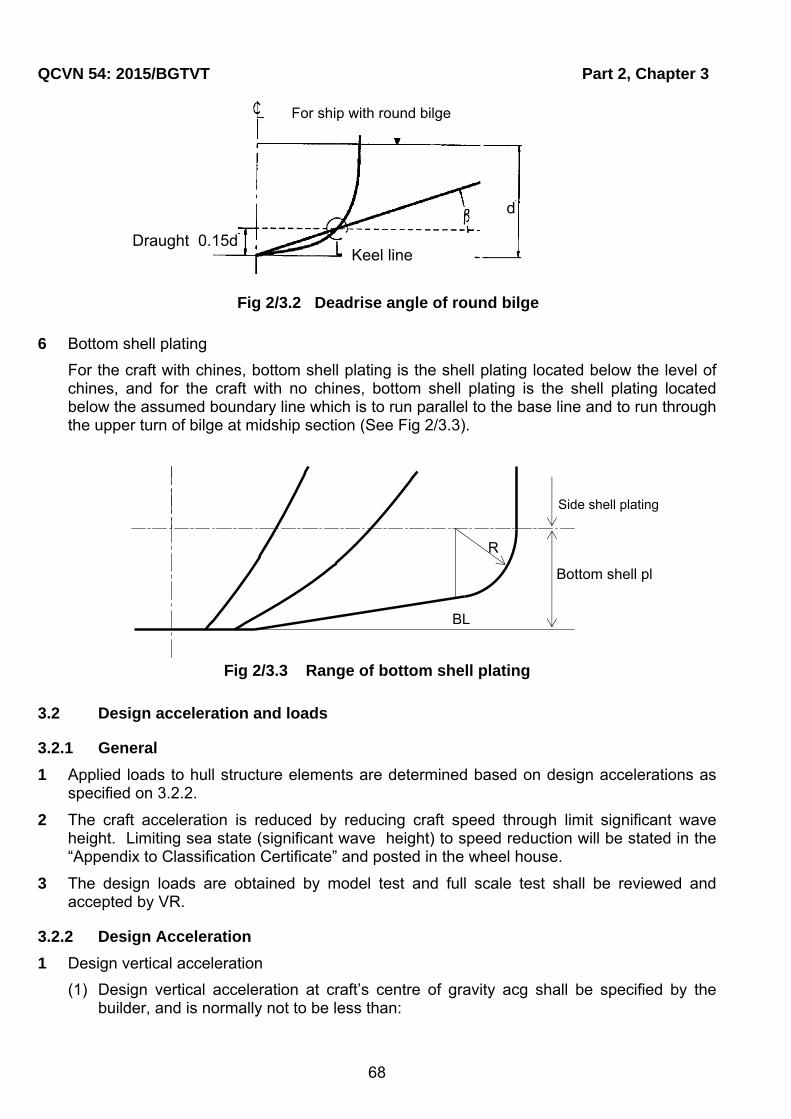
QCVN 54: 2015/BGTVT Part 2, Chapter 3
68
6 Bottom shell plating
For the craft with chines, bottom shell plating is the shell plating located below the level of chines, and for the craft with no chines, bottom shell plating is the shell plating located below the assumed boundary line which is to run parallel to the base line and to run through the upper turn of bilge at midship section (See Fig 2/3.3).
Fig 2/3.3 Range of bottom shell plating
3.2 Design acceleration and loads
3.2.1 General
1 Applied loads to hull structure elements are determined based on design accelerations as specified on 3.2.2.
2 The craft acceleration is reduced by reducing craft speed through limit significant wave height. Limiting sea state (significant wave height) to speed reduction will be stated in the “Appendix to Classification Certificate” and posted in the wheel house.
3 The design loads are obtained by model test and full scale test shall be reviewed and accepted by VR.
3.2.2 Design Acceleration
1 Design vertical acceleration
(1) Design vertical acceleration at craft’s centre of gravity acg shall be specified by the builder, and is normally not to be less than:
BL
Side shell plating
Bottom shell pl
R
Keel line
For ship with round bilge
d
Draught 0.15d
Fig 2/3.2 Deadrise angle of round bilge

Part 2, Chapter 3 QCVN 54: 2015/BGTVT
69
cg g 00.76SS
V 3.2a f g
LL (m/s2)
Where:
Minimum acg = 1.0g0.
0g : Specific gravity, 9.81 (m/s2);
S
V
L : need not be taken greater than 3.0;
gf : acceleration factor dependent of type and area of navigation given in Table 2/3.1.
Table 2/3.1 Acceleration factor
Area of navigation Passenger craft
Cargo craft
Restricted III 1.00 1.00
Restricted II 1.00 1.00
Restricted I 1.00 2.00
Unrestricted 1.00 3.00
(2) The allowable speed corresponding to the design vertical acceleration acg and Significant wave height (Hs) shall be estimated from the formulas:
(a) When S
V3.0
L
2
2h 0 S s WL
cg cgWL S
k g H L .BVa 0,084 50
1650 B 1,025L
(m/s2)
Where:
SH : significant wave height in m;
cg: deadrise angle at LCG in degrees (minimum 10 deg, maximum 30 deg);
WLB : water line breadth at L/2 in m, For twin- and multi hull vessels the total breadth of the hulls (exclusive tunnels) shall be used;
0g : see 3.2.2-1(1);
hk : taken as 1.00.
(b) When S
V3.0
L

QCVN 54: 2015/BGTVT Part 2, Chapter 3
70
Scg 0
S S
H Va 6 0,85 0,35 g
L L
(m/s2)
(3) Unless otherwise established, the design acceleration at different positions along the craft’s length shall not be less than:
v v cga k a
Where:
kv = 1.0 for x/Ls ≤ 0.5 (x longitudinal position from After perpendicular)
kv = 2.0 at Fore perpendicular
A Intermediate values shall be obtained by interpolation method.
3.2.3 Local loads
1 Slamming pressure on bottom
(1) The design slamming pressure on bottom of craft with speed S
V3.0
L , shall be taken
as:
0,30,7 x
sl 1 0 cgcg
501,025P 1,3k d a
nA 50 (kN/m2)
Where:
1k : longitudinal distribution factor from Fig. 2/3.4;
n: number of hulls, 1 for monohulls, 2 for catamarans. Trimarans and other multihulls will be specially considered.;
A: design load area for element considered in m2 A need not for any structure be taken less than 0.002(/d);
For plating A shall not be taken greater than 2.5S2, For l/S < 2.5 A shall be spacing x span S.l;
For stiffener and girder A is taken as the product: spacing x span S.l;
Where:
S: stiffener or girder spacing (m);
l: stiffener or girder span (m);
0d : draught at L/2 in m at normal operation condition at service speed (m);
x : deadrise angle in degrees at transverse section considered (minimum 10°, maximum 30 °);
cg cg,a: see 3.2.2-1.

Part 2, Chapter 3 QCVN 54: 2015/BGTVT
71
Fig 2/3.4 Longitudinal distribution factor
(2) All craft shall be designed for a pitching slamming pressure on bottom as given below:
(a) Pitching slamming pressure on bottom shall be taken as:
0.3Lssl a b W
x S
20d21P k k C 1 0.3/A
tan(β ) L (kN/m2)
Where:
ak : factor taken as:
For plating ka = 1.0;
for stiffeners and girders ka = 1.1 - 20lA/LS (minimum 0.35 and maximum 1.0);
lA: longitudinal extent in m of load area (m);
kb: factor taken as:
for plating and longitudinal stiffeners and girders kb = Ls/(40s) + 0.5, maximum 1.0 (s: span in m of stiffener or girder);
dLs: lowest service speed draft in m at FP measured vertically from waterline to keel line or extended keel line (m);
x : see 3.2.2-2(1)(a);
CW: wave coefficient:
w SC 0,0856L For SL 90 m
2/3
w SC 10,75 300 L / 100 For SL 90 m
Reduction of Cw for restricted service is given as:
Restricted I: 10%
Restricted II: 20%
Restricted III: 40%
(b) Pressure on (a) above shall extend within a length from FP.
P S
S
Vl 0,1 0,15 L
L
0.8
0.6
0.4
0.2
k1 1.0
0 L
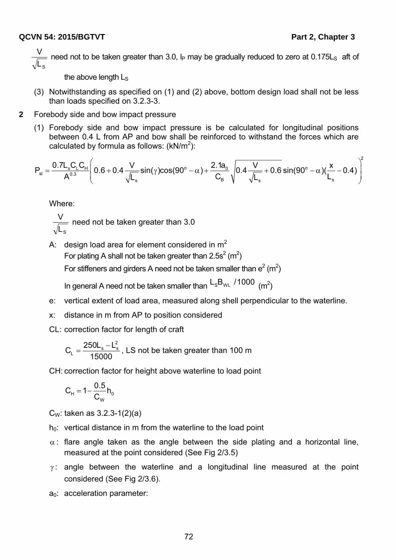
QCVN 54: 2015/BGTVT Part 2, Chapter 3
72
SL
V need not to be taken greater than 3.0, lP may be gradually reduced to zero at 0.175LS aft of
the above length LS
(3) Notwithstanding as specified on (1) and (2) above, bottom design load shall not be less than loads specified on 3.2.3-3.
2 Forebody side and bow impact pressure
(1) Forebody side and bow impact pressure is be calculated for longitudinal positions between 0.4 L from AP and bow shall be reinforced to withstand the forces which are calculated by formula as follows: (kN/m2):
2
o os L H 0sl 0.3
B ss s
0.7L C C 2.1aV V xP 0.6 0.4 sin( )cos(90 ) 0.4 0.6 sin(90 )( 0.4)
A C LL L
Where:
SL
V need not be taken greater than 3.0
A: design load area for element considered in m2
For plating A shall not be taken greater than 2.5s2 (m2)
For stiffeners and girders A need not be taken smaller than e2 (m2)
In general A need not be taken smaller than S WL L B /1000 (m2)
e: vertical extent of load area, measured along shell perpendicular to the waterline.
x: distance in m from AP to position considered
CL: correction factor for length of craft
2
s sL
250L LC
15000
, LS not be taken greater than 100 m
CH: correction factor for height above waterline to load point
H 0W
0.5C 1 h
C
CW: taken as 3.2.3-1(2)(a)
h0: vertical distance in m from the waterline to the load point
: flare angle taken as the angle between the side plating and a horizontal line, measured at the point considered (See Fig 2/3.5)
: angle between the waterline and a longitudinal line measured at the point
considered (See Fig 2/3.6).
a0: acceleration parameter:

Part 2, Chapter 3 QCVN 54: 2015/BGTVT
73
W0 V
S S
C Va 3 C
L L , S
V
LC
50 maximum 0.2
Fig 2/3.5 Flare angle
Fig 2/3.6 Waterline angle
(2) Forebody side and bow pressure shall not be taken less than according to 3.2.3-3.
3 Sea pressure
(1) Pressure acting on the craft’s bottom, side (including superstructure side) and weather decks shall be taken as (kN/m2):
for load point below design waterline:
Water plane/ Hull intersection

QCVN 54: 2015/BGTVT Part 2, Chapter 3
74
00 s W
hP 10h (k 1.5 )C
d
for load point above design waterline:
s W 0P ak (C 0.67h )
Where:
h0: vertical distance in m from the waterline to the load point;
ks: Longitudinal Sea load distribution factor (See Fig. 2/3.7)
= 7.5 aft of amidships;
= 5/CB forward of FP.
Between specified areas is calculated by interpolation method (See Fig. 2/3.7)
a: Factor
=1.0 for craft’s sides and open freeboard deck;
=0.8 đối for weather decks above freeboard deck.
Cw: Factor (see 3.2.3-1(2)(a)).
Fig 2/3.7 Longitudinal Sea load distribution factor
Minimum sea pressures are given in Table 2/3.2
L
Part 2, Chapter 3 QCVN 54: 2015/BGTVT
75
Table 2/3.2 Minimum sea pressures
Area of navigation Sides Weather decks Roof higher than 0.1L above waterline
Unrestricted, Restricted I, II
6.5 5 3
Restricted III 5 4 3
(2) The design pressure on superstructure end bulkheads and deckhouses shall not be taken less than (kN/m2):
s W 0P ak (C 0,67h )
minP 5 (5 0,05L)sin( ) for lowest tier of unprotected front.
min 5P , for aft end bulkheads.
min 5 0,025 sin( )P L , elsewhere.
Where: : is the angle between the bulkhead/side and deck;
h0, Cw, ks takes as specified on 3.2.3-3(1);
a: factor
= 2.0 for lowest tier of unprotected fronts;
= 1.5 for deckhouse fronts;
= 1.0 for deckhouse sides;
= 0.8 elsewhere.
(3) The design pressure on watertight bulkheads (compartment flooded) shall be taken as (kN/m2):
bp 10h
Where hb is vertical distance in m from the load point to the top of bulkhead or to flooded waterline, if deeper
(4) The design pressure on deck or inner bottom forming part of watertight bulkhead shall not be less than for the bulkhead at same level.
4 Liquids
(1) The pressure in tanks shall be taken as the greater of: (kN/m2):
0 v s
0 p
p (g 0,5a )h
p 0,67 g h
0 sp g h 10 , for SL 50 metre
0 s sp g h 0,3L 5 for SL 50 metre
Where:
va : see 3.2.2;
QCVN 54: 2015/BGTVT Part 2, Chapter 3
76
hs: vertical distance in m from the load point to the top of tank;
hp: vertical distance in m from the load point to the top of air pipe or filling station.
(2) The design pressure on wash bulkheads is given by (kN/m2):
tp 3,5l
Where:
lt: the greater distance in m to the next bulkhead forward or aft.
5 Dry cargo, stores and equipment (kN/m2):
0 vp H(g 0,5a )
Where:
va : see 3.2.2;
H: stowage height (m).
Standard values of and H are given in Table 2/3.3
Table 2/3.3 Standard load parameters
Decks Parameters
Weather deck and weather deck hatch covers intended for cargo
H 1.0 2t /m
Sheltered deck, sheltered hatch covers and inner bottom for cargo or stores
0.7 2t /m
H: vertical distance in m from the load point to the deck above. For load points below hatchways H shall be measured to the top of coaming
Platform deck in machinery space H 1.6 2t /m
Accommodation decks H 0.35 2t /m
3.2.4 Deck load supported by pillars
1 Deck load w supported by pillar is not to be less than the value obtained from the following formula:
0 Dw kw SbP (kN)
Where:
S : Distance between the mid-points of two adjacent (before and behind) spans of giders supported the pillars, the bulkhead stiffeners or girders the respective subdivision (m) (see Fig 2/3.8);
b: Mean distance between the mid-points of two adjacent (right or left) spans of beams supported the pillars or frames (m) (See Fig 2/3.8);
DP : Deck load specified in 3.2.3-3 for the deck supported, (kN/m2);
0w : Deck load supported by the upper tween deck pillar, (kN);

Part 2, Chapter 3 QCVN 54: 2015/BGTVT
77
k: As obtained from the following formula according to the ratio of the horizontal distance ai (m) from the pillar to the tween deck pillar above to distance li (m) from the pillar to the pillar bulkhead (See Fig 2/3.8)
3 2
i i
i i
a ak=2 -3 +1
l l
2 Where there are two or more twin deck pillars provided on the deck girder supported by a line of lower pillar, the lower pillar is to be of the scantlings required by -1, taking kw0 for each tween deck pillar provided on two adjacent spans supported by the lower pillars.
3 Where twin deck pillars are shifted from the lower pillars in athwartship direction, the scantlings of lower pillars are to be determined in accordance with the principle in -1 and -2.

QCVN 54: 2015/BGTVT Part 2, Chapter 3
78
3.2.5 Hull girder loads
1 Longitudinal Bending, Shearing and Axial Loads
(1) General
For craft of ordinary hull form with L/D less than 12 and with length less than 50 m, the minimum strength standard is normally satisfied for scantlings obtained from local strength requirements.
(2) Bottom slamming loads bending moment
(a) For craft with sV / L 3.0 a slamming pressure is acting on an area equal to the
reference area AR given below. The area shall be situated with the load point at LCG of the craft. The weight distribution of the hull girder shall be increased by the acceleration at LCG. The hull girder shall be considered out of water.
cg
0R
a1 0.2
gA 1.025k
d
, m2
where:
acg, g0: see 3.2.2;
k=0.7 for crest landing and 0.6 for hollow landing.
(b) Crest landing moment
b
S
l1 l2
aiai
n n m m l
Fig 2/3.8 Measurements of S,b,l...
Bu
lkh
ea
d
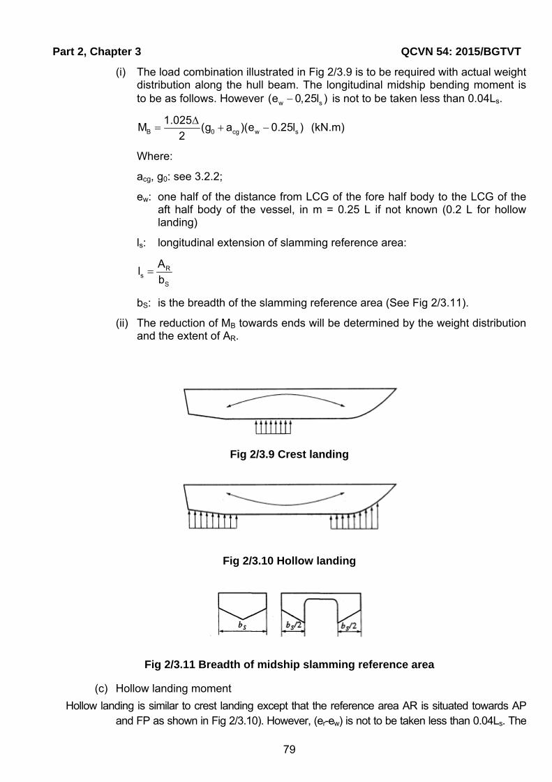
Part 2, Chapter 3 QCVN 54: 2015/BGTVT
79
(i) The load combination illustrated in Fig 2/3.9 is to be required with actual weight distribution along the hull beam. The longitudinal midship bending moment is to be as follows. However w s(e 0,25l ) is not to be taken less than 0.04Ls.
B 0 cg w s
1.025M (g a )(e 0.25l )
2
(kN.m)
Where:
acg, g0: see 3.2.2;
ew: one half of the distance from LCG of the fore half body to the LCG of the aft half body of the vessel, in m = 0.25 L if not known (0.2 L for hollow landing)
ls: longitudinal extension of slamming reference area:
Rs
S
Al
b
bS: is the breadth of the slamming reference area (See Fig 2/3.11).
(ii) The reduction of MB towards ends will be determined by the weight distribution and the extent of AR.
Fig 2/3.9 Crest landing
Fig 2/3.10 Hollow landing
Fig 2/3.11 Breadth of midship slamming reference area
(c) Hollow landing moment
Hollow landing is similar to crest landing except that the reference area AR is situated towards AP and FP as shown in Fig 2/3.10). However, (er-ew) is not to be taken less than 0.04Ls. The
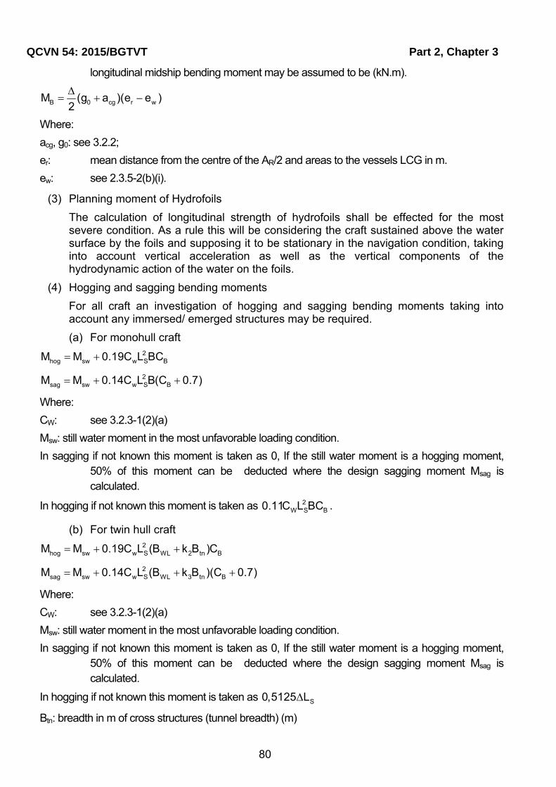
QCVN 54: 2015/BGTVT Part 2, Chapter 3
80
longitudinal midship bending moment may be assumed to be (kN.m).
B 0 cg r wM (g a )(e e )2
Where:
acg, g0: see 3.2.2;
er: mean distance from the centre of the AR/2 and areas to the vessels LCG in m.
ew: see 2.3.5-2(b)(i).
(3) Planning moment of Hydrofoils
The calculation of longitudinal strength of hydrofoils shall be effected for the most severe condition. As a rule this will be considering the craft sustained above the water surface by the foils and supposing it to be stationary in the navigation condition, taking into account vertical acceleration as well as the vertical components of the hydrodynamic action of the water on the foils.
(4) Hogging and sagging bending moments
For all craft an investigation of hogging and sagging bending moments taking into account any immersed/ emerged structures may be required.
(a) For monohull craft 2
hog sw w S BM M 0.19C L BC
2sag sw w S BM M 0.14C L B(C 0.7)
Where:
CW: see 3.2.3-1(2)(a)
Msw: still water moment in the most unfavorable loading condition.
In sagging if not known this moment is taken as 0, If the still water moment is a hogging moment, 50% of this moment can be deducted where the design sagging moment Msag is calculated.
In hogging if not known this moment is taken as 2W S B0.11C L BC .
(b) For twin hull craft 2
hog sw w S WL 2 tn BM M 0.19C L (B k B )C
2sag sw w S WL 3 tn BM M 0.14C L (B k B )(C 0.7)
Where:
CW: see 3.2.3-1(2)(a)
Msw: still water moment in the most unfavorable loading condition.
In sagging if not known this moment is taken as 0, If the still water moment is a hogging moment, 50% of this moment can be deducted where the design sagging moment Msag is calculated.
In hogging if not known this moment is taken as S0,5125 L
Btn: breadth in m of cross structures (tunnel breadth) (m)
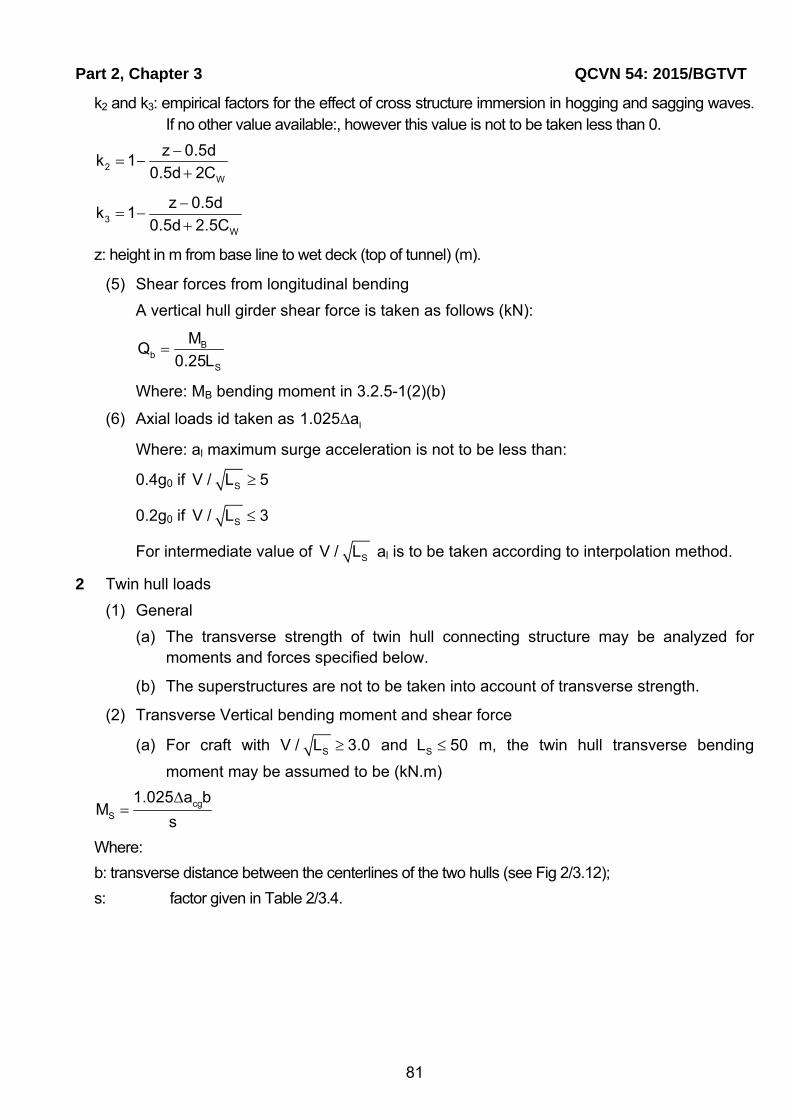
Part 2, Chapter 3 QCVN 54: 2015/BGTVT
81
k2 and k3: empirical factors for the effect of cross structure immersion in hogging and sagging waves. If no other value available:, however this value is not to be taken less than 0.
2W
z 0.5dk 1
0.5d 2C
3W
z 0.5dk 1
0.5d 2.5C
z: height in m from base line to wet deck (top of tunnel) (m).
(5) Shear forces from longitudinal bending
A vertical hull girder shear force is taken as follows (kN):
Bb
S
MQ
0.25L
Where: MB bending moment in 3.2.5-1(2)(b)
(6) Axial loads id taken as l1.025 a
Where: al maximum surge acceleration is not to be less than:
0.4g0 if SV / L 5
0.2g0 if SV / L 3
For intermediate value of SV / L al is to be taken according to interpolation method.
2 Twin hull loads
(1) General
(a) The transverse strength of twin hull connecting structure may be analyzed for moments and forces specified below.
(b) The superstructures are not to be taken into account of transverse strength.
(2) Transverse Vertical bending moment and shear force
(a) For craft with SV / L 3.0 and SL 50 m, the twin hull transverse bending
moment may be assumed to be (kN.m)
cgS
1.025 a bM
s
Where:
b: transverse distance between the centerlines of the two hulls (see Fig 2/3.12);
s: factor given in Table 2/3.4.
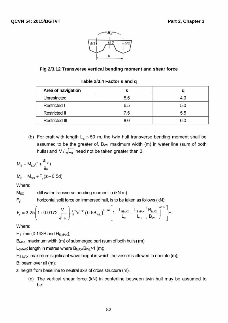
QCVN 54: 2015/BGTVT Part 2, Chapter 3
82
Fig 2/3.12 Transverse vertical bending moment and shear force
Table 2/3.4 Factor s and q
Area of navigation s q
Unrestricted 5.5 4.0
Restricted I 6.5 5.0
Restricted II 7.5 5.5
Restricted III 8.0 6.0
(b) For craft with length SL 50 m, the twin hull transverse bending moment shall be
assumed to be the greater of. BWL maximum width (m) in water line (sum of both
hulls) and SV / L need not be taken greater than 3.
cgS SO
0
aM M (1 )
g
S SO yM M F (z 0.5d)
Where:
MSO: still water transverse bending moment in (kN.m)
Fy: horizontal split force on immersed hull, is to be taken as follows (kN):
2.10
0.1461.05 1.30 BMAX BMAX MAXy S WL 1
S S WLS
L L BVF 3.25 1 0.0172 L d 0.5B 1 H
L L BL
Where:
H1: min (0.143B and HS,MAX);
BMAX: maximum width (m) of submerged part (sum of both hulls) (m);
LBMAX: length in metres where BMAX/BWL>1 (m);
HS,MAX: maximum significant wave height in which the vessel is allowed to operate (m);
B: beam over all (m);
z: height from base line to neutral axis of cross structure (m).
(c) The vertical shear force (kN) in centerline between twin hull may be assumed to be:
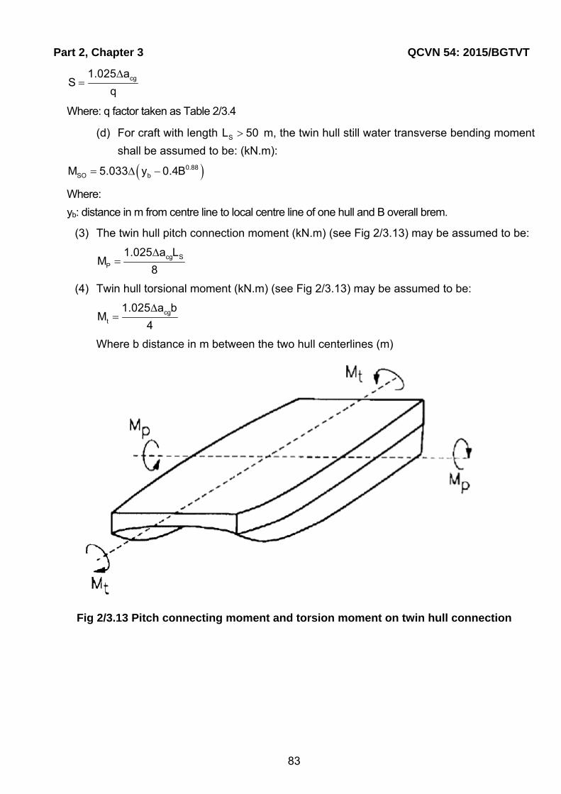
Part 2, Chapter 3 QCVN 54: 2015/BGTVT
83
cg1.025 aS
q
Where: q factor taken as Table 2/3.4
(d) For craft with length SL 50 m, the twin hull still water transverse bending moment
shall be assumed to be: (kN.m):
0.88SO bM 5.033 y 0.4B
Where:
yb: distance in m from centre line to local centre line of one hull and B overall brem.
(3) The twin hull pitch connection moment (kN.m) (see Fig 2/3.13) may be assumed to be:
cg SP
1.025 a LM
8
(4) Twin hull torsional moment (kN.m) (see Fig 2/3.13) may be assumed to be:
cgt
1.025 a bM
4
Where b distance in m between the two hull centerlines (m)
Fig 2/3.13 Pitch connecting moment and torsion moment on twin hull connection

Part 2, Chapter 4 QCVN 54: 2015/BGTVT
84
CHAPTER 4 Scantling Determination of Hull Construction
4.1 Hull construction for steel or aluminium alloys craft
4.1.1 General
1 Application
The requirements of this Chapter apply to the craft constructed in steel or aluminium alloy.
2 Special cases in application
In craft of which scantling length is specially long or in craft to which requirements in this Chapter, for some special reasons, are not directly applicable, hull construction, equipment, arrangement and scantlings are to be at VR’s discretion, notwithstanding the provisions in the preceding 4.1.1-1.
4.1.2 Definition
1 Application
The definitions and characters that appear in this Chapter are to be as specified in this Chapter, unless otherwise specified elsewhere.
2 Yield point or proof stress of the material used
(1) Yield point or proof stress ( y )of rolled steels for hull structure specified in this Chapter is to be given in Table 2/4.1;
(2) Proof stress ( y )of aluminium alloys for hull structure is to be given in Table 2/4.2.
Table 2/4.1 Yield Point or Proof Stress of Rolled Steels for Hull Structure
Symbols of materials Yield point or proof stress (N/mm2)
A,B,D,E 235
A32, D32, E32, F32 315
A36, D36, E36, F36 355
A40, D40, E40, F40 390
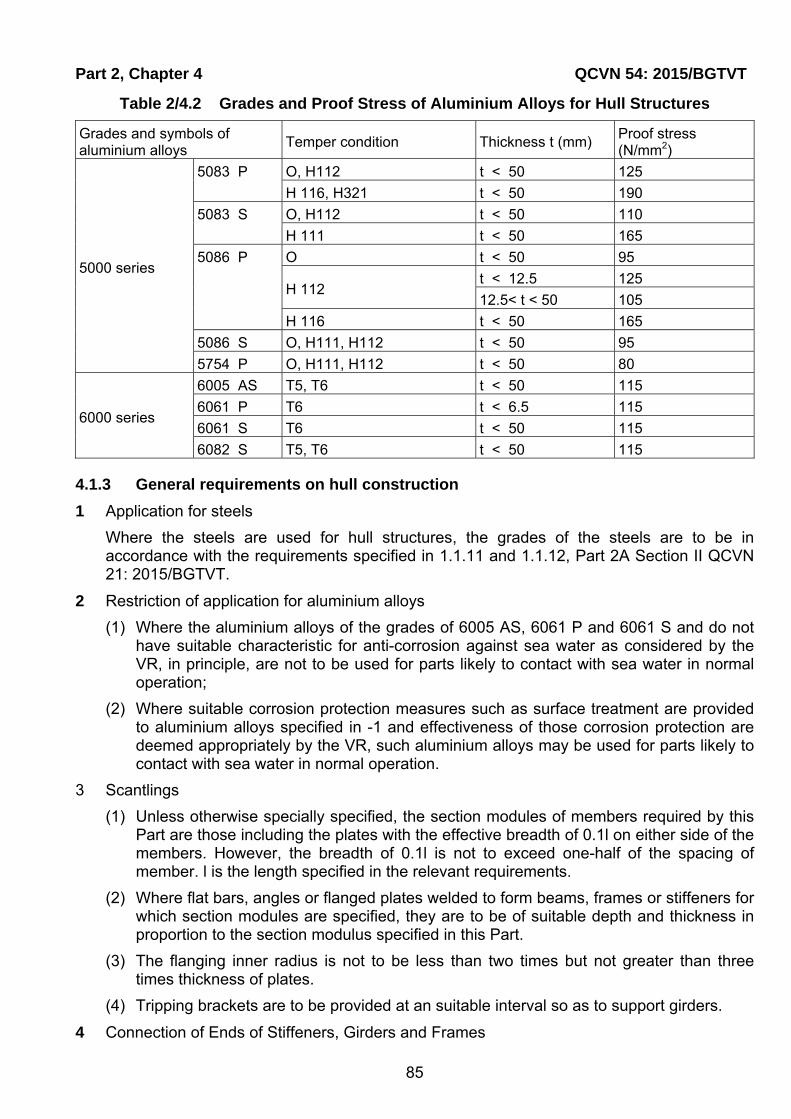
Part 2, Chapter 4 QCVN 54: 2015/BGTVT
85
Table 2/4.2 Grades and Proof Stress of Aluminium Alloys for Hull Structures
Grades and symbols of aluminium alloys
Temper condition Thickness t (mm) Proof stress (N/mm2)
5000 series
5083 P O, H112 t < 50 125
H 116, H321 t < 50 190
5083 S O, H112 t < 50 110
H 111 t < 50 165
5086 P O t < 50 95
H 112 t < 12.5 125
12.5< t < 50 105
H 116 t < 50 165
5086 S O, H111, H112 t < 50 95
5754 P O, H111, H112 t < 50 80
6000 series
6005 AS T5, T6 t < 50 115
6061 P T6 t < 6.5 115
6061 S T6 t < 50 115
6082 S T5, T6 t < 50 115
4.1.3 General requirements on hull construction
1 Application for steels
Where the steels are used for hull structures, the grades of the steels are to be in accordance with the requirements specified in 1.1.11 and 1.1.12, Part 2A Section II QCVN 21: 2015/BGTVT.
2 Restriction of application for aluminium alloys
(1) Where the aluminium alloys of the grades of 6005 AS, 6061 P and 6061 S and do not have suitable characteristic for anti-corrosion against sea water as considered by the VR, in principle, are not to be used for parts likely to contact with sea water in normal operation;
(2) Where suitable corrosion protection measures such as surface treatment are provided to aluminium alloys specified in -1 and effectiveness of those corrosion protection are deemed appropriately by the VR, such aluminium alloys may be used for parts likely to contact with sea water in normal operation.
3 Scantlings
(1) Unless otherwise specially specified, the section modules of members required by this Part are those including the plates with the effective breadth of 0.1l on either side of the members. However, the breadth of 0.1l is not to exceed one-half of the spacing of member. l is the length specified in the relevant requirements.
(2) Where flat bars, angles or flanged plates welded to form beams, frames or stiffeners for which section modules are specified, they are to be of suitable depth and thickness in proportion to the section modulus specified in this Part.
(3) The flanging inner radius is not to be less than two times but not greater than three times thickness of plates.
(4) Tripping brackets are to be provided at an suitable interval so as to support girders.
4 Connection of Ends of Stiffeners, Girders and Frames

QCVN 54: 2015/BGTVT Part 2, Chapter 4
86
(1) Where the ends of girders are connected to bulkheads, tank tops, etc., the end connections of all girders are to be balanced by effective supporting members on the opposite side of bulkheads, tank tops, etc.
(2) Length of the frame-side arm of bracket, connected to the frames or stiffeners of the bulkhead or deep tanks etc., is not to be less the one-eighth of l specified in the relevant requirements, unless otherwise specially specified.
5 Brackets
(1) The thickness of brackets is to be suitably increased where the depth of brackets at throat is less than two-thirds of that of the bracket.
(2) Where lightening holes are cut in brackets, the distance from the circumference of hole to the free flange of bracket is not to be less than the diameter of lightening hole.
(3) Where the length of the longer arm exceeds 800 mm, the free edges of brackets are to be stiffened by flanging or by other means, except where tripping brackets or the like are provided.
6 Modification of span (l) for thicker brackets
(1) Where brackets of not less thickness than that of the girder plates, the value of l specified in 4.1.7-1 of this Chapter may be modified in accordance with the following:
(a) Where the sectional area of face plate of the bracket is not less than one-half of that of the girder and the face plate of the girder is carried to the bulkhead, deck, tank top, etc., l may be measured to a opine 0.15 metres inside the toe of bracket.
(b) Where the sectional area of face plate of the bracket is less than one-half of that of the girder and the face plate of the girder is carried to the bulkhead, deck, tank top, etc., l may be measured to a point where the sum of sectional areas of the bracket and its face plate outside the line of girder is equal to the sectional area of plate of girder, or to a point 0.15 metres inside the toe of bracket, whichever is greater.
(c) Where brackets are provided and the face plates of girders extend along the free edge of brackets to the bulkheads, deck, tank top, etc., even if the free edge of the brackets is curved, l is to be measured to the toe of bracket.
(d) Brackets are not to be considered effective beyond the point where the arm along the girder is 1.5 times the length of arm on the bulkhead, deck, tank top, etc.
(e) In no case is the allowance in l at either end to exceed one-quarter of the overall length of the girder including the part of end connection.
7 Workmanship
(1) The workmanship is to be of the best quality. During construction, the builder is to supervise and inspect in detail every job performed in shed and yard as well.
(2) The connection of structural parts of hull is to be fair and sound.
(3) The edges of plates are to be accurate and fair.
(4) Where frames or beams pass through watertight deck or bulkhead, the deck or bulkhead is to be constructed watertight without using wooden materials or cement.
(5) The details of welded joints and their workmanship are to be as specified in Chapter 1 this Part.

Part 2, Chapter 4 QCVN 54: 2015/BGTVT
87
8 Structural Details
(1) Special attention is to be paid to the arrangements of hull structural members so that welding may be carried out without much difficulty.
(2) Structural discontinuities and the abrupt changes of cross sections are to be avoided as far as practicable, and welding joints are to be properly shifted from places where the stresses may highly concentrate.
(3) Corners of all openings are to be well rounded.
(4) Where rigid structural members with small sectional area, such as brackets, welded on relatively thin plate, at least the toes of members are to be welded just on other rigid members.
(5) Upper ends of sheer strakes in midship part are to be finished smooth and bulwark or equipment is not to be directly welded to the shear strackes.
4.1.4 Longitudinal strength
1 Special case in application
In case there are items for which direct application of the requirements in this Chapter is deemed unreasonable for craft, these items are to be in accordance with the discretion of VR.
2 Loading manual
(1) In order to enable the ship master to adjust the loading of cargo and ballast to avoid the occurrence of unacceptable stress in the craft's structure, the craft, with Lf not less than 100 m, is to be provided with a loading manual approved by VR.
(2) In the loading manual, at least the following items are to be included.
(a) Loading conditions on the basis of which the craft is designed, and the allowable limits of longitudinal still water bending moment and still water shearing force.
(b) Results of calculation of longitudinal still water bending moment and still water shearing force corresponding to the loading conditions.
(c) Allowable limits of local loads applied to hatch covers, deck, double bottom construction, etc., where deemed necessary by VR.
3 Loading Computers
For craft to be provided with a loading manual in accordance with the requirements of the preceding 4.1.4-2, a loading computer capable of readily computing longitudinal still water bending moment and still water shearing force generated in the craft corresponding to all the loading conditions of cargo and ballast having the performance and functions as deemed appropriate by VR is to be provided.
4 Continuity of Strength
Longitudinal members are to be so arranged as to maintain the continuity of strength.
5 Bending Strength at the Midship Part
The section moduli of the transverse sections of hull at the midship part of LS are not to be less than the values obtained from the following formula.

QCVN 54: 2015/BGTVT Part 2, Chapter 4
88
3
all
MZ 10
(cm3)
Where:
M: Bending moment as specified in 3.2.5;
all : Allowable stress obtained from the following formula:
all y0,60 (N/mm2);
y : Yield point or proof stress of the materials used (N/mm2).
6 Calculation of Section Modulus of Transverse Section of Hull
The calculation of section modulus of transverse section of hull is to be based on the following requirements, as given in (1) through (6).
(1) All longitudinal members which are considered effective to the longitudinal strength are to be included in the calculation.
(2) Deck openings on the strength deck are to be deducted from the sectional area used in the calculation of section modulus.
(3) Notwithstanding the requirements in (2), small openings on the strength deck need not be deducted, provided that the sum of their breadths in one single transverse section does not reduce the section modulus at the strength deck or the craft bottom by more than 3%.
(4) Deck openings specified in (2) and (3) include shadow area by drawing two tangential lines with an opening angle of 30 degrees having their apex on the line drawn through the centre of the small openings along the length of the craft.
(5) The section modulus at the strength deck is to be calculated by dividing the moment of inertia of the athwartship section about its horizontal neutral axis by the following distance (a) or (b), whichever is greater.
(a) Vertical distance from the neutral axis to the top of the strength deck beam and the side of the craft (m).
(b) Distance obtained from the following formula:
c
Xk = Y(0,9+0,2 )
B (m)
Where:
X : Horizontal distance from the top of continuous strength members to the centre line of the craft (m)
Y : Vertical distance from the neutral axis to top of continuous strength members (m). In this case, X and Y are to be measured at the point which gives the largest value to the above formula.
(6) The section modulus at craft bottom is to be calculated by dividing the moment of inertia of the athwartship section about its horizontal neutral axis by the following distance (a) or (b), whichever is greater.
(a) Vertical distance from the neutral axis to the base point of D.

Part 2, Chapter 4 QCVN 54: 2015/BGTVT
89
(b) Vertical distance from the neutral axis to the bottom of keel in case where the keel is of hat-type construction.
7 Transverse strength of twin hull craft
(1) The twin hull connecting structure is to have adequate transverse strength related to the design loads and moments given in 3.2.5-2.
(2) When calculating the moment of inertia, and section modulus of the longitudinal section of the connecting structure, the effective sectional area of transverse strength members is in general the net area with effective flange after deduction of openings.
(3) Allowable stresses
(a) The equivalent stress is defined as:
2 2 2c x y x y 3
Where:
x : total normal stress in x-direction
y : total normal stress in y-direction
: total shear stress in the xy-plane
(b) The following total stresses are normally acceptable 2N / mm :
Normal stress s175 / f
Mean shear stress s90 / f
Equivalent stress c s190 / f
Where:
fs: factor is taken as235/σY ;
4.1.5 Plating
1 General
(1) All openings in the shell plating where provided, are to have their corners well rounded and to be compensated as necessary.
(2) In case where the recesses are provided in the shell plating for sea suction or discharge, the shell plating around recesses are to be suitably reinforced as necessary.
(3) The shell platings fitted with water jet propulsion systems are to be increase in thickness or to be doubled as necessary.
(4) The shell platings which are likely to contact with an anchor or anchor chain cables are to be increased in thickness or to be doubled as necessary.
2 Minimum thickness
Minimum thickness of the respective plating is not to be less than the value obtained from the following formula.
sL (mm)

QCVN 54: 2015/BGTVT Part 2, Chapter 4
90
Where, factor as given in Table 2/4.3.
Table 2/4.3 factor
Steels Aluminium Alloys
Bottom shell plating 0.65 fs 0.75 fa
Side shell plating 0.60 fs 0.65 fa
Exposed deck plating - 0.50 fa
Cargo deck plating - 0.50 fa
Other deck plating - 0.45 fa
Watertight bulkhead plating - 0.45 fa
Deep Tank bulkhead plating - 0.50 fa
Note:
fs: Coefficient obtained from the following formula. 235/σY ;
Y : Yield point or proof stress of steels used (N/mm2);
af : Coefficient obtained from the following formula. P128/σ;
P : Proof stress or 70% of the tensile strength of aluminium alloys used in the unwelded condition, whichever is the lesser (N/mm2).
3 Scantling determination of plating
Thickness of plating is not to be less than that obtained from the following formula.
all
QS P
(mm)
Where:
Q: As given by following
For watertight bulkhead plating: 15.8
For other plating : 22.4
S : Spacing of longitudinals or stiffeners (m)
P: Design load specified in 3.2.3 (kN/m2);
all : Allowable stress specified in Table 2/4.4 (N/mm2);

Part 2, Chapter 4 QCVN 54: 2015/BGTVT
91
Table 2/4.4 Design load and allowable stress
all
Bottom shell plating 0.68 y
Side shell plating 0.68 y
Deck plating 0.68 y
Deckhouse/superstructure bulkhead plating
0.91 y
Longitudinal watertight bulkhead plating
0.73 y
Transverse watertight bulkhead plating
0.91 y
Longitudinal deep tank bulkhead plating
0.73 y
Transverse deep tank bulkhead plating
0.91 y
Note:
y : is yield point or proof stress of the material used (N/mm2).
4 Plating of Extruded Shapes
Where platings of extruded shapes are used, bending stress at any point on the subject plating between stiffeners is to be less than allowable stress, provided that the subject plating is to be fixed at positions of stiffeners.
4.1.6 Longitudinal and stiffeners
1 Connections of end of longitudinal and stiffeners
Longitudinal and stiffeners are to be connected to bulkheads, girders or similar rigid construction by brackets in general. However, lug-connection may be substituted at the VR’s discretion.
2 Continuity of longitudinal
Longitudinal are to be continuous or to be connected with careful attention to the continuity of strength.
3 Parts where longitudinal are transformed to transverse stiffeners
In parts where longitudinal are transformed to transverse stiffeners, the special care is to be taken to keep continuity of strength.
4 Scantling determination of longitudinal and stiffeners
Section modulus of longitudinal and stiffeners are not to be less than that obtained from the following formula.
2
all
83.3SPl
(cm3)

QCVN 54: 2015/BGTVT Part 2, Chapter 4
92
Where:
S : Spacing of longitudinal or stiffeners (m);
P : Design load specified in 3.2.3 (kN/m2);
l : Span measured between the adjacent supports of stiffeners including the length of connection(m)
Where girders are provided, l is the distance between the girders.
all : Allowable stress specified in Table 2/4.5 (N/mm2).
Table 2/4.5 Design load and allowable stress
all
Bottom Longitudinal 0.64 y
Bottom frames 0.68 y
Side Longitudinal 0.68 y
Side frames 0.68 y
Longitudinal beams 0.68 y
Transverse beams 0.91 y
Stiffeners fitted on deckhouse/superstructure bulkheads
0.91 y
Longitudinal fitted on watertight bulkheads
0.73 y
Stiffeners fitted on watertight bulkheads
0.91 y
Longitudinal fitted on deep tank bulkheads
0.73 y
Stiffeners fitted on deep tank bulkheads
0.91 y
Note:
y : is yield point or proof stress of the material used (N/mm2).
5 Connecting coefficient
Notwithstanding the provisions in preceding 4.1.6-1, stiffeners for watertight bulkheads and deep tanks may use snips for their ends. In this case, the section modulus for stiffeners is not to be less than the value obtained by multiplying the value specified in 4.1.6-4 with the coefficient f selected from Table 2/4.6.

Part 2, Chapter 4 QCVN 54: 2015/BGTVT
93
Table 2/4.6 Coefficient f
Supported by girders, lug or bracket connection
Only the web of stiffener attached at end
End of stiffeners unattached
Supported by girders, lug or bracket connections
1.0 1.15 1.35
Only the web of stiffener attached at end
1.15 1.35 1.60
End of stiffeners unattached 1.35 1.60 2.00
6 Deck beams supporting special heavy loads
The deck beams supporting special heavy loads in way of deck machinery, etc. are to be properly reinforced by increasing the scantlings of beams, or by the additional deck girders or pillars.
4.1.7 Girders
1 Scantling determination of girders
(1) Section modulus of girders supporting longitudinal or stiffeners are not to be less than that obtained from the following formula.
2
all
mSPl
(cm3)
Where:
m : Coefficient as given in Table 2/4.8 according to the boundary condition of end connection.
S : Breadth of the area supported by the girder (m);
P : Design load specified in 3.2.3 (kN/m2);
I : Span measured between the adjacent supports of girders (m);
all : Allowed stress specified in Table 2/4.7 (N/mm2).
(2) Web sectional area of girder supporting stiffener is not less than the value obtained from the following formula:
all
nSPl
(cm2)
Where:
n: Coefficient as given in Table 2/4.8 according to the boundary condition of end connection.
S, l and P : As specified in preceding (1);
all : Allowed stress specified in Table 2/4.7 (N/mm2).

QCVN 54: 2015/BGTVT Part 2, Chapter 4
94
Table 2/4.7 Design load and allowable stress
all all
Bottom girders 0.68 y 0.42 y
Bottom transverses 0.68 y 0.53 y
Side stringers 0.68 y 0.42 y
Web frames 0.68 y 0.53 y
Deck girders 0.68 y 0.42 y
Deck transverses 0.68 y 0.53 y
Girders and transverses fitted on deckhouse/superstructure bulkheads
0.68 y 0.53 y
Girders fitted on watertight bulkheads 0.73 y 0.42 y
Transverses fitted on watertight bulkheads 0.91 y 0.53 y
Girders fitted on deep tank bulkheads 0.73 y 0.42 y
Transverse fitted on deep tank bulkheads 0.91 y 0.53 y
Note:
y : is yield point or proof stress of material used (N/mm2).
4.1.8 Pillars
1 Pillars in tween decks
Pillars in tween decks are to be arranged directly above those under the deck, or effective means are to be provided for transmitting their loads to the supports below.
2 Pillar in holds
The pillars in holds are to be provided in line with the keel or double bottom girders or as close thereto as practicable, and the structure above and under pillar is to be of ample strength to provide effective distribution of the load.
3 End connection of pillars
The head and heel of pillars are to be secured by thick doubling plates and brackets as necessary.
4 Reinforcement of structures to which pillars are connected
Where the pillars are connected to the deck plating, the top of shaft tunnels, or the frames, these structures are to be efficiently strengthened.

Part 2, Chapter 4 QCVN 54: 2015/BGTVT
95
Table 2/4.8 Coefficient m and n
Boundary Condition (2) m and n
End 1 End 2 At End 1 (1) Mid Span (1) At End 2 (1)
m n m n m n
Fixed Fixed 83.3 5 41.7 3 83.3 5
Supported Fixed 55 3.8 70.3 4.3 125 6.3
Supported Supported 80 5 125 3 80 5
Note:
(1) The position at End 1 and End 2 means the part for 0.2 l from each end. And, Mid Span means the part for 0.6l amidships.
(2) "Fixed" means a case where the scantlings (sectional area, section modulus and sectional moment of inertia) of girder adjacent to the girder concerned are larger than those of the girder concerned. When the scantlings of the girder concerned are larger than those of adjacent girder, the boundary conditions should be "Supported"
(3) In case where boundary conditions are considered as intermediate values of "fixed" and "supported" the severer condition is to be selected.
5 Scantling determination of pillars
The sectional area of pillars is not to be less than the value derived from the following formula:
22
0
21,54
253,3y y
w
lE k
(cm2)
Where:
w : Deck load supported by pillars and is determined by provisions given in 3.2.4 (kN);
y : Yield strength of proof stress of the material used (N/mm2);
l : Distance from the lower end of pillar to the lower side of beam or deck girder supported by the pillar (m);
0k : Minimum radius of gyration of the cross section of pillars (cm);
E : Elasticity constant of the material used (N/mm2).
6 Pillars provided in deep tanks
For the pillar provided in deep tank, hollow typed pillars are not to be used.
4.1.9 Rudders
1 Applications
(1) The requirements in this section apply to the hanging type of a rudder which has no bearing part below the neck bearing.
(2) Rudders other than rudders specified in preceding (1) will be considered in each case by VR.
2 Materials

QCVN 54: 2015/BGTVT Part 2, Chapter 4
96
The rudder stock is to be made of steel forgings. However, steel castings may be used for the material of the rudder stock subject to the approval of VR.
3 Sleeves and bushes
The neck bearing are to be provided with sleeves and bushes.
4 Rudder stocks
(1) The stock diameter (dst) is not to be less than that obtained from the following formula.
3 2
ys
220k V Ah
σ (mm)
Where:
k : Coefficient obtained from the following formula, but not to be less than 9:
1/6W44,5
V
V : As specified in 1.2.2-8 Section I;
A : Area of rudder plate (m2);
h : Vertical distance between the lower end of the neck bearing and the lower end of the rudder (m);
ys : Yield point or proof stress of the material used for the rudder stock (N/mm2);
W : As specified in 1.2.2-14 Section I.
(2) For the craft whose maximum speed is not so fast, the scantling determination of the rudder stock will be considered in each case by VR.
5 Rudder plate
(1) The thickness of the rudder plate consisted of single plate is to be not less than that obtained from the following formula, but is not to be less than 6 mm.
3ysst
yp
σd2b+ct = 0,768(1-k) +C
a+2b c σ (mm)
Where:
k : Ratio of the vertical distance measured between the upper of the rudder to the lower end of rudder and l ;
l : The vertical distance measured between the upper end of the rudder and the lower end of the rudder (mm). (See Fig 2/4.1);
a : Breadth of the rudder at the upper end (mm) (See Fig. 2/4.1).
b : Breadth of the rudder at the lower end (mm) (See Fig. 2/4.1).
c : Breadth of the rudder at the lower end of the rudder stock (mm) (See Fig. 2/4.1).
std : Rudder stock diameter (mm) (See Fig 2/4.1);
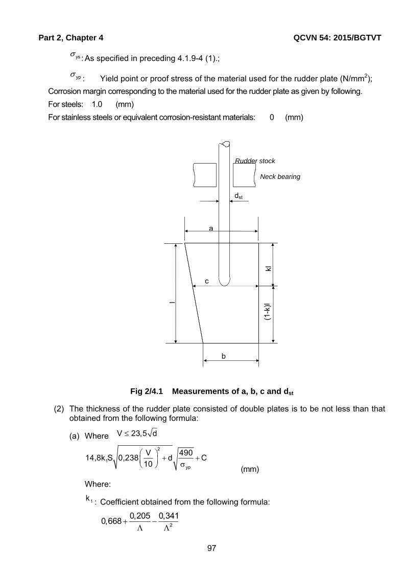
Part 2, Chapter 4 QCVN 54: 2015/BGTVT
97
ys: As specified in preceding 4.1.9-4 (1).;
yp: Yield point or proof stress of the material used for the rudder plate (N/mm2);
Corrosion margin corresponding to the material used for the rudder plate as given by following.
For steels: 1.0 (mm)
For stainless steels or equivalent corrosion-resistant materials: 0 (mm)
Fig 2/4.1 Measurements of a, b, c and dst
(2) The thickness of the rudder plate consisted of double plates is to be not less than that obtained from the following formula:
(a) Where V 23,5 d
2
1yp
V 49014,8k S 0,238 d C
10 (mm)
Where:
1k : Coefficient obtained from the following formula:
2
0,205 0,3410,668
Neck bearing
Rudder stock
b
c
l
a
dst
(1-k
)l kl
QCVN 54: 2015/BGTVT Part 2, Chapter 4
98
: The aspect ratio of the considered panel;
S : Spacing of horizontal or vertical rudder frames, whichever is smaller (m);
V : As specified in preceding 4.1.9-4 (1).;
yp:As specified in preceding 4.1.9-4 (1).;
C : Corrosion margin corresponding to the material used for the rudder plate as given by following.
For steels: : 0.5 (mm)
For stainless steels or equivalent corrosion-resistant materials: 0 (mm)
(b) Where V 23,5 d
2 49012 8 0 741101
yp
V, k S , d C
(mm)
Where:
1k , S, V, yp and C : As specified in (a) above.
4.1.10 Shaft brackets
1 General
Shaft brackets are to be of ample strength and to be strongly connected to the main hull structures.
4.1.11 Engine girders and floors
Scantling determination of the engine girders and floors will be considered appropriate by VR taking into account of the concentration of the heavy load and the vibration generated by the main engines, etc.
4.2 Hull construction for FRP Craft
4.2.1 General
1 Application
(1) The requirements in this section are applied to FRP craft moulded by hand lay-up method or spray lay-up method, using fiberglass reinforcements and unsaturated polyester resins. Wooden craft only covered with FRP or the craft of similar construction are not regarded as FRP craft.
(2) The requirements in this section are applied to FRP craft of less than 35 m in length of normal form and proportion. The requirements for FRP craft of more than 35 m in length will be considered each case by VR.
2 Special Cases in Application
In craft of which scantling length is specially long or in craft to which requirements in 4.2, for some special reasons, are not directly applicable, hull construction, equipment, arrangement and scantling are to be at the discretion of VR, notwithstanding the provisions in the preceding 4.2.1-1.

Part 2, Chapter 4 QCVN 54: 2015/BGTVT
99
4.2.2 Definitions
1 Application
The definitions and characters that appear in 4.2 are to be as specified in 4.2.2, unless otherwise specified elsewhere.
2 Fibreglass reinforcements
The fibreglass reinforcements are glass chopped strand mats (hereinafter referred to as "chopped mats"), glass roving cloths (hereinafter referred to as "roving cloth") and glass roving (hereinafter referred to as "roving") of reinforcements for FRP manufactured from long fibres.
3 Resins
The resins are liquid unsaturated polyester resins for laminating and gelcoat.
4 Laminating
Laminating is an operation of laying succeeding glass fibre reinforcements impregnated with resin before curing or before the preceding layer advances in cure.
5 Bonding
Bonding is an operation of connecting the FRP already advanced in cure with other FRP members, timbers, hard plastic foams, etc. by means of impregnating fibreglass reinforcements with resin.
6 Moulding
Moulding is an operation of manufacturing FRP products with definite form, strength, etc. by means of laminating or bonding.
7 Single skin construction
The single skin construction is a construction composed of FRP single panels moulded with fibreglass reinforcement and resin.
8 Sandwich construction
The sandwich construction is a construction having FRP layers adhered to the both sides of core material such as hard plastic foam, balsa, timber (including plywood), etc.
9 Hand lay-up method
The land lay-up method is a method of manual moulding by impregnating fibreglass reinforcements with resin.
10 Spray lay-up method
The spray lay-up method is a method of moulding by spraying simultaneously fibreglass reinforcements and resin using spray lay-up apparatus.
11 Bending strength of FRP laminates
Bending strength of FRP laminates ( b ) (included FRP laminate of inner and outer layer of sandwich laminates) is the value in N/mm2 obtained from the tests specified in 4.4.4-2(1)(d) Section II QCVN 56: 2013/BGTVT.
12 Modulus of bending elasticity of RFP laminates

QCVN 54: 2015/BGTVT Part 2, Chapter 4
100
Modulus of bending elasticity of FRP laminates ( fE ) (included FRP laminate of inner and outer layer of sandwich laminates) is the value in N/mm2 obtained from the testing specified in 4.4.4-2(1)(e) Section II of QCVN 56: 2013/BGTVT.
13 Tensile strength of FRP laminates
Tensile strength of FRP laminates ( t ) (included FRP laminate of inner and outer layer of sandwich laminates) is the value in N/mm2 obtained from the testing specified in 4.4.4-2(1)(f) or 4.4.4-2(2)(b) Section II of QCVN 56: 2013/BGTVT.
14 Modulus of tensile elasticity of FRP laminates
Modulus of tensile elasticity of FRP laminates ( tE ) (included FRP laminate of inner and outer layer of sandwich laminates) is the value in N/mm2 obtained from the testing specified in 4.4.4-2(1)(g) Section II of QCVN 56: 2013/BGTVT.
15 Sheering strength of sandwich laminates
Sheering strength of Sandwich laminates ( a ) is the value in N/mm2 obtained from the testing specified in 4.4.4-2(2)(c) Section II of QCVN 56: 2013/BGTVT.
16 Compressive strength of core materials for sandwich construction
Compressive strength of core materials for sandwich construction (σc) is the value in N/mm2 obtained from the testing whichever is better in 4.2.1 and 4.3.5-2(2), -3(2) or -4(1) Section II of QCVN 56: 2013/BGTVT.
17 Modulus of compressive elasticity of core materials for sandwich construction
Modulus of compressive elasticity of core materials for sandwich (Ec) is the value in N/mm2 obtained from the testing whichever is better in 4.3.5-2(2), -3(2) or -4(1) Section II of QCVN 56: 2013/BGTVT.
4.2.3 General requirements for hull construction
1 Scantling
(1) Scantling required in 4.2 are specified for FRP craft moulded with fibreglass reinforcements composed of chopped mats or roving cloths and moulded with FRP having the strength specified in 1.2.4 Part 2 of the Regulation.
(2) In case where the scantling of laminates of sandwich construction are calculated, the modulus of bending elasticity of the inner or outer layer of FRP of laminates of sandwich construction may be obtained from the material tests specified in 4.4.4 Section II of QCVN 56: 2013/BGTVT;
(3) In calculating the sectional modulus of structural members, the actual FRP laminates of 150 mm on either side of the web are to be included.
(4) In case where hat-type girders or stiffeners are used for hull construction, spacing for girders, stiffeners and plate panel for scantling determination are to be measured in accordance with following (a) through (c) respectively (See Fig. 2/4.2).
(a) Spacing for girders is to be measured form centre to centre on the girders.
(b) Spacing for stiffeners is to be measured from centre to centre on the stiffeners.
(c) Spacing for plate panel is to be measured between inner webs of hat-type girders or stiffeners which support plate panel.

Part 2, Chapter 4 QCVN 54: 2015/BGTVT
101
2 Weight of fibreglass reinforcements and thickness laminates
(1) The thickness of laminates per play of chopped mats or rowing cloths may be as obtained from the following formula:
10 1000 1000G G G
R G R
W W W
G
(mm)
Where:
GW : Designed weight per unit area of chopped mats or roving cloth (g/m2);
G : Glass content of laminate (ratio in weight ) (%);
R : Specific gravity of cured resin;
G : Specific gravity of chopper mats or roving cloths.
(2) The glass content (G) specified in the preceding (1) is preferable to be the value per ply for the actual laminates. However, it may be taken as the mean glass content of the whole laminates.
(3) The specific gravity of chopped mats or roving cloths ( G )specified in the preceding (1) may be taken as 2.5 in calculation of the thickness, if nothing specially intervenes.;
(4) The specific gravity of cured resin ( R )specified in the preceding (1) may be taken as 1.2 in calculation of the thickness, unless any fillers are used in order to make the resin heavier;
(5) Calculation of the thickness of laminates with fibreglass reinforcements other than chopped mats and cloths is to be in accordance with the discretion of VR.
4.2.4 Longitudinal strength
1 Special case in application
In case there are items for which direct application of the requirements in 4.2 is deemed unseasonable for craft, these items are to be in accordance with the discretion of VR.
Spacing for girders and stiffeners
Spacing for
plate panel
Fig 2/4.2 Spacing for Structural Members
QCVN 54: 2015/BGTVT Part 2, Chapter 4
102
2 Continuity of strength
Longitudinal members are to be arranged as to maintain the continuity of strength.
3 Bending strength at the midship part
The section moduli of the transverse sections of hull at the midship part of LS are not to be less than the value obtained from the following formula.
3
all
M10
σ (cm3)
Where:
M : Bending moment as specified in 3.2.5;
all : Allowable stress obtained from the following formula: 0.10 t (N/mm2);
t : Tensile strength of FRP Laminates (N/mm2).
2.4.4 Calculation of Section Modulus of Transverse Section of Hull
The calculation of the section modulus of the transverse section of the hull is to be based on the following requirements, as given in (1) through (8).
(1) All longitudinal members which are considered effective to the longitudinal strength are to be included in the calculation.
(2) Deck openings on the strength deck are to be deducted from the sectional area used in the calculation of section modulus.
(3) Notwithstanding the requirements in (2), small openings on the strength deck need not be deducted, provided that the sum of their breadths in one single transverse section does not reduce the section modulus at the strength deck or the craft bottom by more than 3%.
(4) Deck openings specified in (2) and (3) include shadow area obtained by drawing two tangential lines with an opening angle of 30 degrees having their apex on the line drawn through the centre of the small openings along the length of the craft.
(5) The section modulus at the strength deck is to be calculated by dividing the moment of inertia of the athwartship section about its horizontal neutral axis by the following distance (a) or (b), whichever is greater.
(a) Vertical distance from the neutral axis to the top of the strength deck beam and the side of the craft (m).
(b) Distance obtained from the following formula:
XY(0,9+0,2 )
B (m)
where:
X : Horizontal distance from the top of continuous strength member to the centre line of the craft (m).
Y : Vertical distance from the neutral axis to top of continuous strength member (m). In this case, X and Y are to be measured at the point which gives the largest value to the above formula.
Part 2, Chapter 4 QCVN 54: 2015/BGTVT
103
(6) The section modulus at the craft bottom is to be calculated by dividing the moment of inertia of the athwartship section about its horizontal neutral axis by the following distance (a) or (b), whichever is greater.
(a) Vertical distance from the neutral axis to the base point of D.
(b) Vertical distance from the neutral axis to the bottom of the keel in the case where the keel is of hat-type construction.
(7) Timbers or structural plywood are to be included in the calculation multiplying the sectional area by the ratio of the modulus of tensile elasticity of the relevant material to that of the FRP.
(8) Where cores of sandwich laminates or cores for moulding are included in the longitudinal strength, the sectional area multiplied by the ratio of the modulus of tensile elasticity of the relevant core to that of the FRP is to be included in the calculation. Where a joint of the core exists for 0.5L amidships, sufficient data with respect to the longitudinal strength and joints are to be submitted to the VR for approval.
5 Transverse strength of twin hull craft
(1) The twin hull connecting structure is to have adequate transverse strength related to the design loads and moments discussed in 3.2.5-2.
(2) When calculating the moment of inertia, and section moduli of the longitudinal section of the connecting structure, the effective sectional area of transverse strength members is in general the net area with effective flange after deduction of openings.
(3) Allowable stresses, N/mm2
Compression or tensile stress t0.25
Shear stress t0.25
4.2.5 Plating
1 General
(1) All openings in the shell plating where provided, are to have their corners well rounded and to be compensated as necessary.
(2) The shell platings which are likely to contact with an anchor or anchor chain cables are to be increased in thickness or to be doubled as necessary.
(3) The shell plating fitted with water jet propulsion systems are to be increased in thickness or to be doubled as necessary.
2 Scantling determination of plating of single skin construction
Thickness of plating of single skin construction is not to be less than that obtained from the following formula.
all
22,4S P
σ (mm)
Where:
S: Spacing of longitudinals or stiffeners (m);
P : Design loads specified in 3.2.3 (kN/m2);

QCVN 54: 2015/BGTVT Part 2, Chapter 4
104
all : Allowable stress specified in Table 2/4.9 (N/mm2).
Table 2/4.9 Design loads and allowable stress
all
Bottom shell plating b0,33 Side shell plating
Deck plating
Deckhouse / superstructure bulkhead plating
Watertight bulkhead plating
Deep Tank bulkhead plating
Note:
b : is bending strength of FRP laminates (N/mm2).
3 Scantling Determination of Plating of Sandwich Construction
(1) The aggregated thickness of outer layer, inner layer and core of sandwich construction is not to be less than obtained from the following formula, whichever is greater:
1C SP (mm)
2 fC t (mm)
Where:
S and p: As specified in preceding 4.2.5-2.
1C : Coefficient obtained from the following formula:
3
a
C
2 3C ,C As given in Table 2/4.10. For intermediate value of α and β the 2 3C ,C is calculated by interpolation method;
a : Shearing strength of sandwich laminates (N/mm2);
ft : Thickness in case of single skin construction specified in preceding 4.2.5-2 (mm).
Table 2/4.10 Value of C2, C3
0.2 0.3 0.4 0.5 0.6 0.7 0.8 0.9 1.0
C2 = 0.8 1.62 1.42 1.31 1.25 1.20 1.16 1.14 1.12 1.10
= 1.0 1.54 1.36 1.25 1.19 1.15 1.12 1.10 1.08 1.07
C3 2.18 2.26 2.33 2.40 2.46 2.52 2.57 2.62 2.67

Part 2, Chapter 4 QCVN 54: 2015/BGTVT
105
(2) The respective thickness of inner layer and outer layer of plating of sandwich construction is not to be less than that obtained from the following formula. In no case, however, it is to be less than 2.4 mm:
4 4343,6 C S P (mm)
Where:
4
c4
c f c
E1 1C =
t E σ
ct : Thickness of core (mm);
cE : Modulus of compressive elasticity of core (N/mm2);
fE : Modulus of bending elasticity of inner layer or outer layer of FRP laminates of sandwich construction (N/mm2);
c : Compressive strength of core (N/mm2);
S, P: As specified in previous (1).
(3) The core of sandwich construction composing a panel is to be, as a rule, composed by one layer. The thickness of core is not to be larger than 25 mm. However, the composition of core different from these is to be at the discretion of VR.
(4) The ratio of the thickness of outer and inner layers of FRP is not to be less than 0.8. In case where the ratio of the thickness of outer and inner layers is less than 0.8, the construction will be specially considered by VR.
(5) The cores may be reckoned in the strength at the discretion of VR.
4.2.6 Longitudinal and stiffeners
1 General
Connection of ends of longitudinal and stiffeners is to be in accordance with the requirements specified in 4.1.6-1 through 4.1.6-3 and 4.1.6-5 in this Chapter.
2 Scantling Determination of Longitudinal and Stiffeners
(1) Sectional modulus of longitudinal and stiffeners is not to be less than that obtained from the following formula.
2
all
83,3SPl
σ (cm3)
Where:
S: Spacing of longitudinal or stiffeners (m);
P : Design load specified in 3.2.3 (kN/m2);
l : Span measured between the adjacent supports of stiffeners including the length of connection (m). Where girders are provided, l is the distance from the heel of end connection to the first girders or the distance between the girders;

QCVN 54: 2015/BGTVT Part 2, Chapter 4
106
all : Allowable stress specified in Table 2/4.11 (N/mm2).
Table 2/4.11 Design load and allowable stress
all
Bottom longitudinals and frames t0,33 Side longitudinals and frames
Deck beams
Longitudinals and stiffeners fitted on deckhouse/ superstructure bulkheads
Longitudinals and stiffeners fitted on watertight
bulkheads
Longitudinals and stiffeners fitted on deep tank
bulkheads.
Note:
t : is tensile strength of FRP laminates (N/mm2).
4.2.7 Girders
1 Scantlings of Girder
Section modulus of girder supporting stiffeners is not to be less than the value obtained from the following formula:
2
all
mSPl
σ (cm3)
Where:
m : Coefficient as given in Table 2/4.13 according to the boundary condition of end connection;
S : Breadth of the area supported by the girders (m);
P : Design load specified in 3.2.3 (kN/m2);
l : Span measured between the adjacent supports of girders (m);
all : Allowable stress specified in Table 2/4.12 (N/mm2).
2 Web sectional area of girder supporting stiffener is not less than the value obtained from the following formula:
all
nSPl
(cm2)
Where:
n : Coefficient as given in Table 2/4.13 according to the boundary condition of end connection;

Part 2, Chapter 4 QCVN 54: 2015/BGTVT
107
S and l: specified in -1;
P : Load specified in Chapter 3 corresponding to the girder under consideration;
all : Allowed stress specified in Table 2/4.12 (N/mm2).
Table 2/4.12 Design load and Allowable Stress
all all
Bottom girders and transverses 0.33 t 0.19 t Side stringers and web frames
Deck girders and transverses
Girders and transverses fitted on deckhouse /
superstructure bulkheads
Girders and transverses fitted on watertight
bulkheads
Girders and transverses fitted on deep tank
bulkheads.
Note:
t : is tensile strength of FRP laminates (N/mm2).
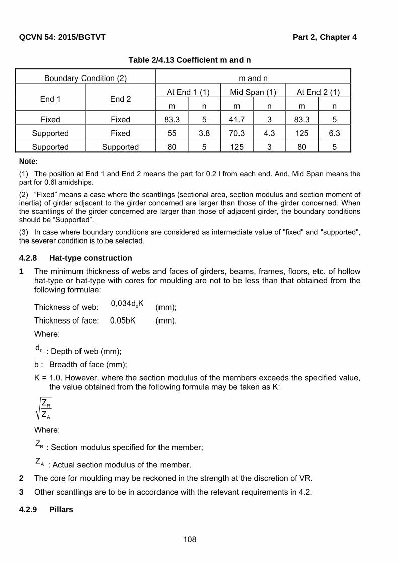
QCVN 54: 2015/BGTVT Part 2, Chapter 4
108
Table 2/4.13 Coefficient m and n
Boundary Condition (2) m and n
End 1 End 2 At End 1 (1) Mid Span (1) At End 2 (1)
m n m n m n
Fixed Fixed 83.3 5 41.7 3 83.3 5
Supported Fixed 55 3.8 70.3 4.3 125 6.3
Supported Supported 80 5 125 3 80 5
Note:
(1) The position at End 1 and End 2 means the part for 0.2 l from each end. And, Mid Span means the part for 0.6l amidships.
(2) “Fixed” means a case where the scantlings (sectional area, section modulus and section moment of inertia) of girder adjacent to the girder concerned are larger than those of the girder concerned. When the scantlings of the girder concerned are larger than those of adjacent girder, the boundary conditions should be “Supported”.
(3) In case where boundary conditions are considered as intermediate value of "fixed" and "supported", the severer condition is to be selected.
4.2.8 Hat-type construction
1 The minimum thickness of webs and faces of girders, beams, frames, floors, etc. of hollow hat-type or hat-type with cores for moulding are not to be less than that obtained from the following formulae:
Thickness of web: 00,034d K (mm);
Thickness of face: 0.05bK (mm).
Where:
0d : Depth of web (mm);
b : Breadth of face (mm);
K = 1.0. However, where the section modulus of the members exceeds the specified value, the value obtained from the following formula may be taken as K:
R
A
Z
Z
Where:
RZ : Section modulus specified for the member;
AZ : Actual section modulus of the member.
2 The core for moulding may be reckoned in the strength at the discretion of VR.
3 Other scantlings are to be in accordance with the relevant requirements in 4.2.
4.2.9 Pillars
Part 2, Chapter 4 QCVN 54: 2015/BGTVT
109
1 Application
Construction of pillars is to be in accordance with 4.1.8.
4.2.10 Rudders
1 Application
Construction of rudders is to be in accordance with 4.1.9.
4.2.11 Shaft brackets
1 Application
Construction of shaft brackets is to be in accordance with 4.1.10.
4.3 Direct strength calculation
4.3.1 General
1 General
Except the requirements for the minimum thickness specified in 4.1.5-2, the scantling of hull structural members may be determined based upon the direct strength calculation subject to the approval of VR.
In case the direct calculation are used, structural model, loads, allowable stress and others are to be VR’s discretion.
When direct strength calculation in preceding (1) were executed for determination of scantling, necessary documents and information are to be submitted.
4.4 Buckling control
4.4.1 General
Detailed assessment of buckling strength may be required as deemed necessary by VR.
4.5 Fatigue control
4.5.1 General
Detailed assessment of fatigue strength may be required as deemed necessary by VR.

Part 2, Chapter 5 QCVN 54: 2015/BGTVT
110
CHAPTER 5 Equipment and Painting
5.1 Equipment
5.1.1 General
1 Anchors, Chain cables, wire ropes and fibre ropes are to be in compliance with the requirements in Chapter 2, Chapter 3, Chapter 4 and Chapter 5, Part 7B Section II of QCVN 21: 2015/BGTVT;
2 The reduction of requirements in this Chapter may be specially considered at the request of owner and at the discretion of VR.
5.1.2 Neo
1 Each craft shall be provided with anchor arrangement consisting of at least one anchor, anchor wire rope (chain cable), machinery for dropping and hoisting the anchor, and holding the craft at anchor, as well as a stopper for securing the anchor in the hawse pipe.
Where the weight of the anchor is less than 25 kg, anchor machinery may be omitted.In such case, the craft shall be provided with a device for securing the anchor wire rope (chain cable) for riding the craft at anchor.
2 Equipment numbers
(1) Equipment number is the value obtained from the following formula:
2/3
cN =W +2,0C+0,1A
Where:
W : Full load displacement as defined in 1.2.2-14 Section I;
C, A : Value as specified in the following (a), (b) and (c).:
(a) C is the value obtained from the following formula:
C=fB+ hb Where:
f: Vertical distance, at the midship, from the designed maximum load line to the top of uppermost continuous deck beam at side (m);
Summing up to the products of the height h (m) and breadth b (m) of superstructure, deckhouse or trunk which are located above the uppermost continuous deck and also have a breadth greater than B/4. In this calculation, sheer and trim may be ignored.
(b) A is the value obtained from the following formula:
A=fL+ hl Where:
f: As specified in (a);
hl : Summing up to the products of the height h(m) and length l (m) of superstructures, deckhouses or trunks which are located above the uppermost continuous deck within the

Part 2, Chapter 5 QCVN 54: 2015/BGTVT
111
length of craft and also have a breadth greater than B/4.
(c) In the application of (a) and (b), screens and bulwarks more than 1.5 metres in height are to be regarded as parts of superstructures or deckhouses.
(2) In catamarans, the projected area of air gap between the designed maximum load line and the wet deck may be subtracted from the value C specified 5.1.1-2(1)(a).
3 Anchors
(1) The mass of individual bower anchor is not to be less than value determined by the following formula:
cQ k.N (kg)
Where:
cN : equipment number;
k = 1.75 for ships of unrestricted service;
k = 1.65 for ships of restricted area of navigation I;
k = 1.50 for ships of restricted area of navigation II;
k = 1.35 for ships of restricted area of navigation III;
The mass of individual bower anchor may vary 7% of the value calculated from the formula;
(2) Where high holding power anchors are used, the mass of each anchors may be 0.75 the mass calculated from -3(1) above;
(3) Where super high holding power anchors are used, the mass of each anchors may be 0.5 the mass calculated from -3(1) above;
(4) If two of anchor is fitted, the weight of each anchor may be deducted 30%.;
4 Chain cables
(1) The total length (l) of chain cables, in metre, for bower anchor is not to be less than the value determined by the formula:
l 7,5 Q 20
(2) The breaking strength, Fst, in kN, of the anchor wire rope (chain cable) shall not be less than:
stF 0,06kQ
where:
k: holding power factor of the used anchor equal to:
= 3 for normal holding power anchors;
= 6 for high holding power anchors;
= 9 for super high holding power anchors.
(3) The wire rope shall be connected with the anchor shackle by the joining shackle.

QCVN 54: 2015/BGTVT Part 2, Chapter 5
112
(4) The craft not fitted with anchor machinery may be provided with synthetic fibre ropes instead of wire ropes (chain cables).The breaking strength in kN, of the synthetic fibre rope shall be not less than::
89
syn av stF 0.124 F
Where:
av : average relative elongation in breaking a synthetic fibre rope, in %, but not less
than 30%.
(5) The end of the synthetic fibre rope shall be spliced into a thimble and secured to the anchor, if possible, by a wire rope (chain cable) section at least 10 m long which complies with the requirements of (2) and( 3).
The length of the wire rope (chain cable) section may be included in the required length of the rope determined by the formula in (1).
5 Mooring and Towing Arrangements
(1) The number of mooring lines on HSC shall be not less than that determined by the following formula::
cn 1.5 0.004N
The results of calculations using the Formula (1) shall be rounded off to both sides to the nearest figure. In all cases, the number of mooring lines shall not be less than two.
(2) The length of each mooring line l, in m, shall not be less than 1.5 times the length of the craft with rounding off to the nearest 5 m. With cN 500 the length of a mooring line
may be taken equal to 1.2Ls.
(3) The breaking strength, in kN, of wire ropes as a whole shall not be less than that obtained from the following formula:
cF 4.9 N
(4) Mooring lines may be of steel wire, natural fibre or synthetic fibre material.The breaking strength of synthetic fibre ropes shall not be less than that obtained from the following formula::
89
syn avF 0.07 F
av : average relative elongation in breaking a synthetic fibre rope, in %, but not less
than 30 %;.
Irrespective of the breaking strength regulated by formulae (3) and (4), mooring lines made of natural fibre or synthetic fibre material less than 20 mm in diameter shall not be used. On agreement with the Register the use of ropes of smaller diameter for a craft with equipment number less than is allowed.
(5) Towing arrangements shall be provided to enable craft to be safely towed in the worst intended conditions. Other arrangements on the craft may be used for towing purposes.
(6) The maximum permissible speed at which the craft may be towed shall be included in the operational manual.
6 Miscellaneous
(1) All craft are to be provided with suitable appliances for handling of anchors.

Part 2, Chapter 5 QCVN 54: 2015/BGTVT
113
(2) Chain cable and wire ropes are to be stored in chain lockers or on the drums. The inboard end of a chain cable is to be secured to the hull through a strong eye plate by means of shackle or other equivalent means.
(3) Bower anchors are to be located on the suitable position to prevent any damage on hull structures in the cases of anchoring operation. If necessary, anchor bell mouths are to be fitted for this purpose.
(4) The arrangements for anchoring, towing and berthing and the local craft structure and the design of the anchor, towing and berthing arrangements and the local craft structure are to be such that risks to persons carrying out anchoring, towing or berthing procedures are kept to a minimum.
(5) All anchoring equipment, towing bitts, mooring bollards, fairleads, cleats and eyebolts are to be so constructed and attached to the hull that, in use up to design loads, the watertight integrity of the craft will not be impaired.
(6) Under any operating load up to the breaking strength of the anchor cable or mooring lines, the loads on the bitts, bollards, etc., is not to result in any damage to the hull structure that will impair its watertight integrity. A strength margin of at least 20% above the resultant load based on the minimum specified breaking strength of the relevant cable or warp shall be required.
5.2 Hatchways, machinery space openings and other deck openings
5.2.1 General
1 Relaxation from the requirements
Relaxation from the requirements in this Section will be specially considered where the craft have an unusually large freeboard.
2 Position of exposed deck openings
For the propose of this Section, two positions of exposed deck openings are defined as follows:
Position I:
Upon exposed freeboard and raised quarter decks and exposed superstructure decks
situated forward of a point located 0.25 fL abaft the fore end of fL .
Position II:
Upon exposed superstructure decks abaft the forward 0.25 fL abaft the fore end of fL .
5.2.2 Hatchways
1 Application
The construction and the closing means of cargo and other hatchways are to be comply with the requirements in Chapter 18, Part 2A or Chapter 17, Part 2B Section II of QCVN 21: 2015/BGTVT unless otherwise specified in this 5.2.
2 Height of hatchway coamings
The minimum height of coamings above the upper surface of deck is to be in accordance with Part 7.
3 Closing appliances
QCVN 54: 2015/BGTVT Part 2, Chapter 5
114
(1) Hatchway openings on exposed decks are to be provided with efficient weathertight closing appliances with cleating devices.
(2) Hatchway covers fitted with hatchway openings in way of escape routes are to be capable of being operated from both sides.
5.2.3 Closing means for access openings in superstructure end bulkheads
1 Closing Means for Access Openings
(1) The doors to be provided on the access openings in the end bulkheads of enclosed superstructures are to be in accordance with the requirements in (a) through (e):
(a) The doors are to be made of suitable materials having equivalent strength to those of the bulkheads and to be permanently and rigidly fitted up to the bulkheads.
(b) The doors are to be rigidly constructed, to be of equivalent strength to that of the intact bulkhead and to be weathertight when closed.
(c) The means for securing weathertightness are to consist of gaskets and clamping devices or other equivalent devices and to be permanently fitted up to the bulkheads or door itself.
(d) The doors are to be operated from both sides of the bulkheads.
(e) Hinged doors are, as a rule, to open outward.
(2) The height of sills of access openings above upper surface of deck specified in preceding (1) is not to be less than the minimum height specified in Part 7;
In principle, portable sills are not permitted.
5.2.4 Machinery space openings
1 Protection of Machinery Space Openings
Machinery space openings are to be enclosed by rigid castings.
2 Construction
The construction of exposed machinery space castings, machinery space castings below the freeboard deck or within enclosed superstructures or deckhouses will be considered in each case by VR.
3 Access openings to machinery spaces
(1) All access openings to machinery spaces are to be located in protected positions as far as possible and provided with doors capable of being closed and secured from both sides. Such doors in exposed machinery casings on the freeboard deck are to comply with the requirements in 5.2.3-1 (1).
(2) The height of sills of door ways in machinery casings above upper surface of deck is not to be less than the minimum height specified in Part 7.
4 Miscellaneous openings in machinery casings
(1) Coamings of any fiddley, funnel and machinery space ventilator in an exposed position on the freeboard or superstructure deck are to be as high above the deck as reasonable and practicable.
Part 2, Chapter 5 QCVN 54: 2015/BGTVT
115
(2) In exposed positions on the freeboard and superstructure decks, fiddley openings and all other openings in the machinery casings are to be provided with strong weathertight covers permanently fitted up in their proper positions.
(3) Annular spaces around funnels and all other openings in the machinery casings are to be provided with closing means capable of being operated from outside the machinery space in case of a fire.
5.2.5 Companionways and other deck openings
1 Manholes and flush deck openings
Manholes and flush deck openings in exposed positions on the freeboard and superstructure decks or within superstructures other than enclosed superstructures are to be closed by covers capable of being made watertight. These covers are to be secured by closely spaced bolts or to be permanently fitted up.
2 Companionways
(1) Access openings in the freeboard deck are to be protected by enclosed superstructures, or by deckhouses or companionways of equivalent strength and weathertightness.
(2) Access openings in exposed superstructure decks or in the top of deckhouses on the freeboard deck which give access to a space below the freeboard deck or a space within an enclosed superstructure are to be protected by efficient deckhouses or companionways.
(3) Doorways in deckhouses or companionways such as specified in (1) and (2) are to be provided with doors complying with the requirements in 5.2.3. Where, however, companionways are to be enclosed with boundary wall fitted with closing means complying with the requirements in 5.2.3, the external doors need not to be weathertight.
(4) The height of sills of door ways in deckhouses or companionways such as specified in preceding (1) through (3) above upper surface of deck is not to be less than the minimum height specified in Part 7.
3 Openings to cargo spaces
Access and other openings to cargo spaces are to be provided with closing means capable of being operated from outside the spaces in case of a fire. Such closing means for any openings leading to any other space inboard the craft is to be of equivalent strength to that of the intact bulkhead of cargo spaces.
5.3 Bulwarks, guardrails, freeing arrangements, cargo ports and other similar openings, side scuttles, ventilators and gangways
5.3.1 Bulwarks and guardrails
1 General
(1) Efficient guardrails or bulwarks are to be provided around all exposed decks.;
(2) Guardrails specified in (1) above are to comply with the followings:
(a) Fixed, removable or hinged stanchions are to be fitted about 1.5 m apart. Removable or hinged stanchions are to be capable of being locked in the upright position.
QCVN 54: 2015/BGTVT Part 2, Chapter 5
116
(b) At least every third stanchion is to be supported by a bracket or stay. Alternatively, measures deemed appropriate by the VR are to be taken.
(c) Where necessary for the normal operation of the ship, steel wire ropes may be accepted in lieu of guardrails. The wires are to be made taut by means of turnbuckles.
(d) Where necessary for the normal operation of the ship, chains fitted between two fixed stanchions and/or bulwarks are acceptable in lieu of guardrails.
2 Dimensions
(1) The height of bulwarks or guardrails specified in -1 is to be at least 1 metre from the upper surface of deck, provided that where this height would interfere with the normal operation of the craft, a less height may be permitted where the VR is satisfied that adequate protection is provided.
(2) The clearance below the lowest course of guardrails on superstructure and freeboard decks is not exceed 230 mm, and those for the other courses are not to be exceed 380 mm.
(3) Guardrails fitted on superstructures and freeboard decks are to have at least three courses. In other locations, guardrails are to have at least two courses.
3 Construction
(1) Bulwarks are to be strongly constructed and effectively stiffened on their upper edges;
(2) Bulwarks are to be supported by stiffened stays connected to the deck in way of beams or at effectively stiffened positions. The spacing of these stays on the freeboard deck is not to be more than 1.8 metres.
4 Miscellaneous
(1) Gangways and other openings in bulwarks are to be well clear of the breaks of superstructures.
(2) Where bulwarks are cut to form gangways or other openings, stays of increased strength are to be provided at the ends of the openings.
(3) The plating of bulwarks in way of mooring pipes is to be doubled or increased in thickness.
(4) At ends of superstructures, the bulwark rails are to be bracketed either to the superstructure end bulkheads or to the stringer plates of the superstructure deck, or other equivalent arrangements are to be made so that the abrupt change of strength may be avoided.
5.3.2 Freeing Arrangements
1 General
(1) Where bulwarks on the weather parts form wells, ample provision is to be made for rapidly freeing the deck off water.
(2) Ample freeing ports are to be provided for clearing any space other than wells, where water is liable to be shipped and to remain.
(3) In craft having superstructures which are open at either or both ends, adequate provision for freeing the space within superstructures is to be provided.
Part 2, Chapter 5 QCVN 54: 2015/BGTVT
117
2 Freeing Port Area
Freeing Port Area shall not to be taken less than values specified in Part 7.
3 Arrangement of Freeing Ports
(1) Two-thirds of the freeing port area required by -2 is to be provided in the half of the well near the lowest point of the sheer curve, and the remaining one-third is to be evenly spread along the remaining length of the well.
(2) The freeing ports are to have well rounded corners and their lower edges are to be as near the deck as practicable.
3.2.4 Construction of Freeing Ports
(1) Where both the length and the height of freeing ports exceed 230 mm respectively, freeing ports are to be protected by rails spaced approximately 230 mm apart.
(2) Where shutters are provided to freeing ports, ample clearance is to be provided to prevent jamming. Hinge pins or bearings of the shutters are to be of non-corrosive materials.
(3) Where the shutters referred to in (2) are provided with securing appliances, these appliances are to be of approved construction.
5.3.3 Cargo Ports and Other Similar Openings
1 Arrangement of Bow Doors
(1) Bow doors are in principle to be situated above the freeboard deck;
(2) Where bow doors are leading to a complete or long forward enclosed superstructure, an inner door which forms a part of collision bulkhead is to be fitted in the above superstructure. Where the craft which are not engaged in international voyage and for are for restricted service, an inner doors may be omitted at the discretion of the VR.
(3) Vehicle ramp way may be arranged for this purpose, provided that it forms a part of collision bulkhead and satisfies the requirements for position of the collision bulkhead as stipulated in 2.2.1-2 Part 2;
(4) Bow doors are to be so fitted as to ensure effective protection to inner doors.
2 Arrangement of Side Doors and Stern Doors
(1) The lower edge of any openings of side doors and stern doors which are provided abaft the collision bulkhead is in principle not to be below a line which is parallel to the freeboard deck at the craft's side and has the lowest point on the uppermost load line.;
(2) Where side door and stern door are unavoidably provided below the line as stipulated in (1), the following conditions are to be satisfied:
(a) Compartment being equivalent to watertight bulkhead in strength and watertightness is to be provided and the second door is to be fitted for the compartment.
(b) Detecting device for sea water leakage is to be provided in the compartment.
(c) Drainage means of the compartment with a screw down stop valve capable of being controlled from easily accessible position is to be provided.

QCVN 54: 2015/BGTVT Part 2, Chapter 5
118
(3) The number of door openings is to be kept to the minimum compatible with design and proper operation of the craft.
3 Construction of Doors and Inner Doors
(1) Bow door, side door and stern door to have openings below the freeboard deck (hereinafter collectively referred to as the door(s) in this Chapter) are to be made watertight;
(2) Doors leading to an enclosed superstructure and the inner door as stipulated in 5.3.3-1(2) in this Chapter (hereinafter referred to as the inner door in this Chapter) are to be made weathertight;
(3) Strength of the door and the inner door is in principle to be equivalent to that of the surrounding hull structure;
(4) Doors and inner doors are adequately stiffened and means is to be provided to prevent lateral or vertical movement of the doors when closed. Hinges and lifting arms of the door and the inner door are to be rigidly fixed with the door plating and the hull structure;
(5) Where a bow door is provided in craft with a rounded nose bow and a large stem angle, impact force by water is to be considered;
(6) Doors and inner doors are in principle to open outwards;
(7) Gutter waterways and scuppers are to be provided to prevent spread of leaked water over the deck.
4 Closing Devices of Doors and Inner Door
(1) Closing devices of sufficient strength are to be provided to the door and the inner door so that they are able to keep strength equivalent to surrounding hull structure in closed condition;
(2) The closing devices in (1) above are to be simple and easily accessible;
(3) Where hydraulic cleating is applied, the system is to be mechanically lockable in closed condition even in the event of failure of the hydraulic system;
(4) Cleating devices and supporting devices are in principle to be provided at appropriate intervals and as close to each corner of the door;
(5) Caution plate giving instructions that all closing devices are to be closed before leaving ports and warning indicator lamps are to be provided at the operation panel of remote control of the door;
(6) Indicators showing whether the doors are opened or closed are to be provided with at the wheel house where deemed necessary by the VR;
(7) Devices are to be arranged for the door and the inner door to lock them in open position;
(8) Design load for closing devices of the door is to be as considered appropriate by the VR.
5.3.4 Side Scuttles
1 General
Part 2, Chapter 5 QCVN 54: 2015/BGTVT
119
(1) No side scuttle is to be provided in such a position as its sill is below a line drawn
parallel to the freeboard deck at side and having its lowest point 0.025 fB or 500 mm whichever is greater, above the uppermost load line;
(2) No side scuttle is in principle to be provided to any space solely engaged in carriage of cargoes. Where side scuttles are provided to such spaces, the special consideration will be give by the VR.
2 Application
(1) Side scuttles to spaces below the freeboard deck and those provided to sunken poop are to be class B side scuttles complying with the requirements in Chapter 7, Part 7B Section II QCVN 21: 2015/BGTVT or equivalent thereto;
(2) Side scuttles to spaces within enclosed superstructures, those fitted up to the side and front walls of deckhouses and companionways on the freeboard deck which have unprotected deck openings leading to spaces below the freeboard deck inside and those exposed to direct blow of seas are to be class C side scuttles with hinged dead-light complying with the requirements in Chapter 7 Part 7B Section II QCVN 21: 2015/BGTVT or equivalent thereto;
(3) Where an openings in the superstructure deck or in the top of deckhouse on the freeboard deck which gives access to spaces below the freeboard deck or to a space within an enclosed superstructure is protected by the deckhouse or companion, side scuttles fitted in spaces which give direct access to an open stairway are to be class C side scuttles with hinged dead-light complying with the requirements in Chapter 7 Part 7B Section II QCVN 21: 2015/BGTVT or equivalent thereto.
3 Protection of side scuttles
All side scuttles in way of spaces where they are liable to be damaged are to be protected by strong gratings.
5.3.5 Other windows
1 Application
(1) Side scuttles to spaces within enclosed superstructures, those fitted up to the side and front walls of the deckhouses and companionways on the freeboard deck which have unprotected deck openings leading to spaces below the freeboard deck inside and those exposed to direct below of seas are to be class C side scuttles with hinged dead-light complying with the requirements in or equivalent thereto.
(2) Spaces which are fitted with windows applying this are not to be the reserve of buoyancy.
2 General
Rectangular windows on the surrounding of deck houses or superstructures are to be of fixed type except wheel house windows or windows used for means of escape.
3 Construction
(1) Windows are to be rigidly framed and strongly fitted on the hull structures.
(2) Thickness of glass is not to be less than 5 mm or that obtained from the following formulae, whichever is the greater:

QCVN 54: 2015/BGTVT Part 2, Chapter 5
120
W
aP
K (mm)
Where:
a : Length of shorter side of window (mm);
: As given by following formula corresponding to the aspect ratio of window:
0.73751.0414 0.0244
or 0.75 whichever is the lesser, Where Λ is aspect ratio
of window (length of longer /length of shorter of window);
P : Design loads for deck houses and superstructures as specified in 3.2.3;
WK : Material factor
= 225 for toughened safety glass;
= 190 for polycarbonate.
(3) Polycarbonate window panes are to overlap their frames with not less than 0.03 b mm;
(4) The thickness of window panes may be reduced from that given by the formula in (2) if they are satisfactorily pressure tested as described in (6) and (7);
(5) The test pressure is not to be taken less than 4 times the design pressure as specified in 3.2.3 for toughened safety glass, and 3.5 times the design pressure for polycarbonate;
(6) During the testing the window is to be fitted in similar arrangement as to be installed onboard the craft.
The testing may be considered satisfactory provided:
- no failure in window or attachment method;
- no leakages occur.
(7) Large glass doors or windows in the aft end of superstructures or deckhouses will be especially considered.
4 Closing Appliances
(1) Dead-lights storm shutters are to be fitted with following windows:
(a) All windows on the first tier above freeboard deck;
(b) Windows on the second tier above freeboard deck and deemed necessary by VR.
(2) Notwithstanding (1), dead-lights may be fitted according to Table 2/5.1 below;

Part 2, Chapter 5 QCVN 54: 2015/BGTVT
121
Table 2/5.1 Minimum number of deadlights in relation to number of windows
Location Unrestricted Restricted I Restricted II Restricted III
Below main deck 100% 100% 100% 100%
Superstructure front 1st tier
100% see (3) 0
Superstructure side see (3) 0 0
Deckhouse front 2nd tier and above
see (3) 0 0
Deckhouse side 2nd tier and above
see (3) 0 0
(3) Areas for which there is not 100% requirement are to be provided with adequate means (e.g. canvas) for temporary replacement of a damaged window, protecting crew and passengers from sea spray and wind.
5 Other Requirement
Windows used for means of escape are also to be comply with the requirements in Chapter 5, Part 5 of this Regulation. The minimum clear opening is not to be less than 600 mm 600 mm.
5.3.6 Ventilators
1 Height of Ventilator Coamings
The height of ventilator coamings above the upper surface of the deck is not less tan the minimum height specified in Part 7.
2 Connection
Ventilator coamings are to be efficiently connected to the deck and, where their height exceeds 900 mm, are to be specially supported.
3 Closing Appliances
(1) Ventilators to machinery and cargo spaces are to be provided with means for closing openings capable of being operated form outside the spaces in case of a fire;
(2) All ventilator openings on exposed decks are to be provided with efficient weathertight closing appliances. Where the height of coaming of any ventilator exceeds 1 metre above the freeboard and raised quarter decks, such closing appliances may be omitted unless requirement in (1).
4 Ventilators for accommodation spaces
Ventilator intakes for the accommodation spaces are to be so arranged as to prevent from absorbing gases from machinery spaces and fuel oil tanks.
5 Ventilators for deckhouses
The ventilators for deckhouses which protect the companionways leading to spaces below the freeboard deck are to be equivalent to those for the enclosed superstructures.
5.3.7 Gangways

QCVN 54: 2015/BGTVT Part 2, Chapter 5
122
Satisfactory means (in the form guardrails, life lines, gangways or under deck passages, etc.) are to be provided for the protection of the crew in getting to and from their quarters, the machinery space and all other parts used in the necessary work of the craft.
5.4 Painting and protection against corrosion
5.4.1 Painting
1 General
(1) All structural members of steel work are to be coated with a suitable paint. For structural members inside of oil tanks, painting may be omitted.
(2) Structural members of aluminium alloys work which are exposed to the corrosive circumstances (for example, structural members directly facing to sea water or its splash) are to be coated with suitable paint. It is recommended that other structural members are also to be coated with suitable paint.
(3) Outer shell of FRP craft are to be coated with suitable gelcoat or composition having the property of low water absorption.
5.4.2 Protection against corrosion
1 General
(1) Where two or more kinds of different metallic materials (for example, steel and aluminium alloy) are used for structural members of a craft, different metals are to be insulated by the electrical insulation having the property of anti water absorption against galvanic corrosion.
(2) Where two or more kinds of different metallic materials (for example, steel and aluminium alloy) are used for structural members of a craft and such different metals are close to each other in salt water, a suitable method against galvanic corrosion is to be applied.

Part 3, Chapter 1 QCVN 54: 2015/BGTVT
123
PART 3 MACHINERY INSTALLATIONS
CHAPTER 1 GENERAL
1.1 General
1.1.1 Scope
1 The requirement of this Part apply to the main propulsion machinery, power transmission systems, shafting systems, propellers, waterjet propulsion systems, prime movers other than main propulsion machinery, boilers, thermal oil heaters, incinerators, pressure vessels, auxiliaries, piping systems and their control systems (hereinafter referred to as "Machinery installations" in this Part).
2 Machinery installations which are unusual and considered impracticable to meet the requirements of this Part may be accepted provided that they are deemed by VR to be equivalent to those specified in this Part.
3 For machinery installations with novel design features, VR may apply the requirements of the Regulation so far as practicable and other requirements as considered necessary by VR.
4 For machinery installations which are considered appropriate by VR, some requirements in this Part may be modified by taking their capacity, purposes and operating conditions into account.
5 The terms specified in this chapter are in accordance with the requirements of 1.1.5 Part 3 Section II QCVN 21: 2015/BGTVT.
6 The drawings and data to be submitted in connection with machinery installations are to conform to the requirements specified in each Chapter of this Part, in addition to those specified in 2.1.2-1(2) Part 1B of this Regulation.
1.1.2 Materials
Materials intended to be used for machinery installations are to be selected considering the purpose and conditions of their service. Materials intended for principal components are to be of those tested and inspected in accordance with the requirements specified in this Part.
1.2 General Requirements for Machinery Installations
1.2.1 General
1 The machinery installations are to be properly fixed and to be of construction and arrangement to facilitate operation, inspection and maintenance.
2 The machinery installations are to be of a design and construction adequate for the service for which they are intended and are to be so installed and protected as to reduce to a minimum any danger to persons on board, due regard being paid to moving parts, hot surfaces and other hazards.

QCVN 54: 2015/BGTVT Part 3, Chapter 1
124
3 When the following machinery is fitted singly on board, special consideration is to be given to the reliability of the machinery and its components. For craft in which unconventional machinery is used as the main propulsion machinery and propulsion shafting system, provision of additional machinery capable of ensuring the ship to proceed at navigable speed in the possible event of failure of the machinery may be requested by VR.
(1) For diesel ships:
Diesel engines used as the main propulsion machinery, highly elastic couplings, reduction gears and propulsion shafting systems.
(2) For gas turbine ships:
Gas turbine engines used as the main propulsion machinery, compressors, combustors, reduction gears and propulsion shafting systems.
(3) For electric propulsion ships:
Propulsion motors, reduction gears and propulsion shafting systems.
4 Means are to be provided whereby normal operations of main propulsion machinery can be sustained or restored even though one of the essential auxiliaries becomes inoperative. Special consideration is to be given to the malfunctioning of:
(1) A generator set which serves as a main source of electrical power;
(2) The fuel oil supply systems for boilers or engines;
(3) The sources of lubricating oil pressure;
(4) The sources of water pressure;
(5) An air compressor and a receiver for starting or control purposes;
(6) The hydraulic, pneumatic or electrical means for control in main propulsion machinery including controllable pitch propellers;
However, having regard to overall safety consideration, a partial reduction in propulsion capability from normal operation may be accepted.
5 Such information as is necessary to ensure that machinery can be installed correctly regarding such factors as operating conditions and limitations are to be made available by the manufacturers.
6 The following machinery, are to be designed to operate under the conditions given in Table 3.1.1, as fitted in the ship. Deviation from the angles given in this Table may be permitted, taking into consideration the type, size and service conditions of the ship.
7 Machinery installations are to be fitted with adequate safety monitoring and control devices in respect of speed, temperature, pressure and other operational functions.
8 Special consideration is to be given to the design, construction and installation of the machinery installations so that any mode of vibrations, accelerations, shocks, etc., shall not cause undue stresses in normal operating ranges.
9 Measures are to be taken to reduce machinery noise in machinery spaces to acceptable levels. If this noise can not be sufficiently reduced the source of excessive noise is to be
Part 3, Chapter 1 QCVN 54: 2015/BGTVT
125
suitably insulated or isolated or a refuge from noise is to be provided if the space is required to be manned. Ear protectors are to be provided for personnel required to enter such spaces, if necessary.
10 To prime movers used for lift or attitude control arrangements, the requirements concerning to the main propulsion machinery are to be applied.
Table 3/1.1 Angle of Inclination
Type of machinery installations
Athwart ships(2) Bow-and-stern(2)
Static
inclination
(List)
Dynamic
inclination
(Rolling)
Static
inclination
(Trim)
Dynamic
inclination
(Pitching)
Main propulsion machinery
Essential auxiliary boilers
Prime movers driving generators
(excluding those for emergency)
Auxiliary machinery (excluding auxiliary machinery for specific use, etc.), and their driving units
15°
22.5°
5°(3)
7.5°
Emergency installations (emergency generators, emergency fire pumps and prime movers drive them) Switchgears(1) (Circuit breakers, etc.)
Equipment for automatic and remote controls
22.5°
22.5°
10°
10°
Notes: (1) Up to an angle of inclination of 45°, undesired switching operations or operational changes are not
to be caused. (2) Athwart ships and bow-and-stern inclinations may occur simultaneously. (3) Where the length of the ship exceeds 100 m, the fore-and-aft static angle of inclination may be
taken as follows:
Where:
θ : The static angle of inclination (°)
L : Length of the ship (m) specified in 1.2.20 Part 1A Section II QCVN 21: 2015/BGTVT.
1.2.2 Astern Power
1 Sufficient power for going astern is to be provided to secure proper control of the ship in all normal circumstances.
2 For the main propulsion systems with reversing gears, controllable pitch propellers, waterjet propulsion systems or electric propeller drive, running astern is not to lead to the overload of propulsion machinery.

QCVN 54: 2015/BGTVT Part 3, Chapter 1
126
1.2.3 Limitation in the Use of Fuel Oil
1 Except for cases as specified in (1) to (3) below, no fuel oil with a flash point (to be determined by an approved closed cup method) of less than 60 °C is to be used:
(1) In emergency generators, fuel oil with a flash point of not less than 43 °C may be used;
(2) Subject to such additional precautions as it may consider necessary and on condition that the ambient temperature of the space in which such fuel oil is stored or used shall not be allowed to rise to within 10 °C below the flashpoint of the fuel oil, the general use of fuel oil having a flashpoint of less than 60 °C but not less than 43 °C may be permitted;
(3) The use of fuel oil having a flashpoint of less than 43 °C may be permitted provided that such fuel oil is not stored in any machinery space and subject to the approval by VR of the complete installation.
1.2.4 Fire Protections
1 Flange joints and special joints (screwed joints, mechanical joints, etc.) fitted in flammable oil piping such as fuel oil, lubricating oil, and such flammable oil systems are not to be located right above boilers, steam pipelines, thermal oil pipelines, exhaust gas pipings, silencers, exhaust gas driven turbo blowers or other highly heated surfaces, and to be arranged far apart therefrom, as far as practicable, unless proper means approved by VR are provided against leaking or spraying of the oils from these joints and systems.
2 All surfaces of machinery installations with temperature exceeding 220 °C where impingement of flammable liquids may occur as a result of a system failure are to be effectively insulated. The insulation is to be imprevious to flammable liquids and vapours.
3 The driving units for fuel oil transfer pumps and other similar fuel oil pumps, fuel purifiers, forced draft fans for boilers and ventilating fans serving machinery spaces are to be capable of being stopped from an easily accesible position outside the space concerned in the event of a fire in the space where they are located and its vicinity. The means provided for stopping the ventilation fans of the machinery spaces are to be entirely separated from those of other spaces.
4 Machinery installations are to be free from leakages of the fuel oil, lubricating oil and other flammable oils, unhealthy gases and flammable gases which may cause fire, so far as is available. For those from which these oils may leak, proper means of leading the leaked oils to other safe location are to be provided.
5 Machinery installations are to be free from leakage of such gases as to harm human health or cause fire. The possible machinery installation is to be placed at such a position as the gases can be easily drained off to a well-ventilated place.
6 Provision is to be made to drain all excess fuel and oil to a safe position so as to avoid a fire hazard.

Part 3, Chapter 1 QCVN 54: 2015/BGTVT
127
7 Structures constructed with combustible materials such as woods and the like are not to be located above internal combustion engines and their surroundings, except where protected adequately by metal plate, rockwool or other fire-resisting materials.
8 The means specified in below are to be taken for each space where pre-treatment machinery installations for flammable liquid such as purifiers, oil heaters, etc., are installed, unless other adequate means deemed appropriate by VR are provided.
(1) Each space in which the main components in the above system are installed is to be separated from other machinery installations, enclosed by steel bulkheads extending from deck to deck with self-closing steel doors.
(2) A fixed fire detection and fire alarm system is to be provided.
(3) A fixed fire-extinguishing system capable of being activated from outside the room is to be provided.
(4) Independent mechanical ventilation or a ventilation arrangement which can be isolated from the machinery space ventilation is to be provided.
A closing arrangement of the above ventilation openings capable of being activated from a position close to where the above fixed fire-extinguishing system is to be provided.
1.2.5 Ventilating Systems for Machinery Spaces
Machinery spaces are to be adequately ventilated so as to ensure that when machinery or boilers therein are operating at full power, an adequate supply of air is maintained to the spaces for the safety and comfort of personnel, for the operation of the machinery and for the prevention of accumulation of flammable gases.
1.2.6 Communication between Navigating Bridge and Control Stations for Speed and Direction of Thrust of Propellers
1 Communication between navigating bridge and control stations for the control of speed and direction of thrust of propellers are to comply with following requirements:
(1) At least two independent communication means are to be provided for communicating orders from the navigating bridge to the position in the machinery space or in the control room from which the speed and direction of thrust of the propellers are normally controlled. One of these means is to be an engine room telegraph which provides visual indication of the orders and responses both on the navigating bridge and in such control station mentioned above;
(2) Means of communication as deemed appropriate by VR, are to be provided from the navigating bridge and the engine room to any position, other than those specified in (1) above, from which the speed or direction of thrust of the propellers may be controlled.
1.2.7 Engineers Alarm

QCVN 54: 2015/BGTVT Part 3, Chapter 1
128
An engineers alarm is to be provided to be operated from the engine control room or at the
manoeuvring platform as appropriate, and is to be clearly audible in the engineers
accommodation.
1.3 Tests
1.3.1 Shop Tests
1 Before installation on board, machinery installations are to be tested according to the following requirements at the plants:
(1) The tests for diesel engines are to be carried out in accordance with 2.6.1 Part 3 Section II QCVN 21: 2015/BGTVT;
(2) The tests for gas turbines are to be carried out in accordance with 4.5.1 Part 3 Section II QCVN 21: 2015/BGTVT;
(3) The tests for power transmission systems are to be carried out in accordance with 5.5.1 Part 3 Section II QCVN 21: 2015/BGTVT;
(4) Shaftings, Propellers and Waterjet Propulsion Systems
(a) Stern tubes, propeller shaft sleeves and stern tubes shaft sleeves are to be subjected to hydrostatic tests specified in 6.3.1 Part 3 Section II QCVN 21: 2015/BGTVT;
(b) Propellers are to be tested in accordance with 7.4.1 Part 3 Section II QCVN 21: 2015/BGTVT;
(c) Waterjet propulsion systems are to be subjected to the following tests:
(i) Hydrostatic tests at a pressure 1.5 times the design pressure for impeller casing;
(ii) Balancing test of the impeller;
(iii) Hydrostatic tests at a pressure of at least 0.2 MPa or 1.5 times the design pressure whichever is higher for the forward bearing tube of the main shaft and the sealing device tubes.
(5) Boilers, Thermal Oil Heaters, Incinerators and Pressure Vessels
(a) Boilers with design pressure exceeding 0.35 MPa are to be tested in accordance with 9.10.1 Part 3 Section II QCVN 21: 2015/BGTVT;
(b) Boilers with design pressure not exceeding 0.35 MPa are to be tested in accordance with 9.11.3-1 Part 3 Section II QCVN 21: 2015/BGTVT;
(c) Thermal oil heaters are to be subjected to the test specified in above (a);
(d) Pressure vessels are to be tested in accordance with 10.9.1 Part 3 Section II QCVN 21: 2015/BGTVT.
(6) Pipes, Valves, Pipe Fittings and Auxiliaries
Pipes, valves, pipe fittings and auxiliaries are to be subjected to tests specified in 12.6.1 Part 3 Section II QCVN 21: 2015/BGTVT.

Part 3, Chapter 1 QCVN 54: 2015/BGTVT
129
(7) Steering Gears
Steering gears are to be subjected to tests specified in 15.5.1 Part 3 Section II QCVN 21: 2015/BGTVT.
(8) Refrigerating Equipment
Refrigerating Equipment is to be tested in accordance with 17.4.1 Part 3 Section II QCVN 21: 2015/BGTVT.
(9) Automatic and Remote Control Systems
Automatic and remote control systems are to be subjected to the tests specified in 18.7.1 Part 3 Section II QCVN 21: 2015/BGTVT. In addition, the requirement specified in 18.7.2 Part 3 Section II QCVN 21: 2015/BGTVT are to be complied with.
1.3.2 Tests after Installation on Board
1 After installation on board, the following tests are to be carried out:
(1) Verification inspection of installation or fixing condition of machinery.
(2) Performance tests for overspeed protective devices, fuel oil leaking alarms from the injection pipes, lubricating oil low pressure alarming and automatic stopping devices, emergency stopping devices and cooling water high temperature alarming devices of diesel engines.
(3) Performance tests for overspeed protective devices, lubricating oil low pressure alarming and automatic stopping devices, emergency stopping devices, flame-out alarming, excessive vibration alarming, fire detection devices in enclosures exhaust gas high temperature alarming devices and, cooling water high temperature alarming devices of gas turbine.
(4) Performance tests for lubricating oil low pressure alarming of power transmission systems.
(5) Tests for leakage under working oil pressure of stern tube sealing devices.
(6) Force-fitting tests to measure and record the pull-up length for propellers force-fitted on the propeller shaft.
(7) For boilers with design pressure exceeding 0.35 MPa, popping tests for safety valves and function tests for the safety devices and alarm devices.
(8) For boilers with design pressure not exceeding 0.35 MPa, function tests for the safety devices.
(9) For thermal oil heaters, popping tests for safety valves and function tests for the safety devices and alarm devices.
(10) For incinerators with maximum capacity not less than 34.5 kW:
(a) Operation tests of the safety devices and alarming devices and burning tests;
(b) Tests for assigning the safety working temperature.
(11) For piping systems welded aboard ships between pipes or between pipes and valves, hydrostatic tests as deemed appropriate by VR. These tests may be waived with
QCVN 54: 2015/BGTVT Part 3, Chapter 1
130
confirmation of no defects by appropriate non destructive tests deemed appropriate by VR.
(12) For auxiliaries (excluding auxiliary machinery for specific use, etc.,) running tests as deemed appropriate by VR. However, in the case of machinery having passed the tests specified in above 1.3.1(6), the test methods on board may be suitably modified at the discretion of VR.
(13) For fuel oil piping systems, thermal oil piping systems and heating coils in tanks, leak tests at a pressure of 1.5 times the design pressure or 0.4 MPa, whichever is the greater.
(14) For steering gears:
(a) Leak tests for the hydraulic oil systems at least a max. working pressure, after installed on board;
(b) Each operation test, after installed on board.
(15) For mooring winches:
(a) Operation tests for 15 minutes in each direction at max. speed under no load;
(b) Function tests for the drum brake under the operating condition specified in (a);
(c) Notwithstanding the requirements specified (a) and (b), where there are a plurarity of units of the same type, the period of testing and number of units to be tested may be reduced.
(16) For the piping systems of refrigerating equipment, which are exposed to a pressure of the primary refrigerant, leak tests at a pressure of 90% of the design pressure.
(17) For automatic and remote control systems, it is to be ensured that the systems can operate effectively, respectively under as far practical condition as possible. However, part of the tests may be carried out during sea trials.
1.3.3 Mass-production Equipment
For equipment manufactured by mass-production system deemed appropriate by VR, the test procedure suited to the production method may be accepted in place of the tests specified in this Regulation upon the request of the manufacturer, notwithstanding the requirements of 1.3.1 above.
1.3.4 Omission of Tests
Where machinery installations have test certificates which are deemed appropriate by VR, a part or all of tests for the machinery specified in 1.3.1 may be omitted.
1.3.5 Additional Tests
VR may require, when deemed necessary, other tests than those specified in this Part.

Part 3, Chapter 2 QCVN 54: 2015/BGTVT
131
CHAPTER 2 DIESEL ENGINES
2.1 General
1.1.1 Scope
The requirements of this Chapter apply to the diesel engines used for main propulsion machinery, electric generators and auxiliary machinery (excluding auxiliary machinery for specific use, etc., hereinafter the same in this Chapter).
2.1.2 Drawings and Data
1 Drawings and data to be submitted are generally as follows:
(1) Drawings and data for approval
(a) Engine particulars;
(b) Details of welding procedure for principal components (including tests and inspections);
(c) Crankshaft (including component details, shaft coupling bolts, balance weights and their fastening bolts);
(d) Connecting rod and its bearings (including bolts details) of 4 stroke cycle engines;
(e) Thrust shaft (if integral with engine);
(f) Arrangement of foundation bolts (including foundation bolts, chocks and stoppers);
(g) Structural detail and arrangement of crankcase explosion relief valves;
(h) Material specifications of principal components;
(i) High pressure oil pipes for driving exhaust valves with its shielding;
(j) High pressure fuel oil pipes with its shielding and clamping;
(k) Piping arrangements fitted to engine (including fuel oil, lubricating oil, cooling oil, cooling water, pneumatic and hydraulic systems, and indicating size, materials and working pressure of pipes);
(l) Sectional assembly of exhaust driven turbo blowers.
(2) Drawings and data for reference:
(a) A list containing all drawings and data submitted (with relevant drawing numbers and revision status);
(b) Longitudinal section of the engine;
(c) Transverse cross-section of the engine;
(d) Bedplate and thrust block (if integrated with engine);
(e) Frames;

QCVN 54: 2015/BGTVT Part 3, Chapter 2
132
(f) Cylinder cover, cylinder jacket and cylinder liner;
(g) Piston and gudgeon pins;
(h) Tie rods (including coupling and set-screws);
(i) Assembly of piston and piston rods;
(j) Piston rods;
(k) Connecting rod and its bearings (including bolts details) of 2 stroke cycle engines;
(l) Assembly of thrust bearings;
(m) Assembly of crossheads;
(n) Camshaft driving gear and assembly of cam and camshafts;
(o) Rocker valve gears;
(p) Fuel oil injection pumps;
(q) Main bearing bolts;
(r) Cylinder cover fixing bolts and valve box fixing bolts;
(s) Flywheel (in the case of a power transmission component);
(t) Engine control system diagram (including monitorings, safety and alarm systems);
(u) Construction and arrangement of thermal insulation for exhaust pipes fitted to the engine;
(v) Construction and arrangement of dampers, detuners, balancers or compensators, bracings, and calculation sheets on balancing and prevention of vibration of the engine;
(w) Operation and service manuals of the engine;
(x) Other drawings and data deemed necessary.
2.1.3 Materials, Construction and Strength
1 Materials intended for the principal components of diesel engines and their non-destructive test are to conform to the requirements specified in 2.2.1 Part 3 Section II QCVN 21: 2015/BGTVT.
2 Where the principal components of diesel engines are of welded construction, they are to comply with the requirements specified in Chapter 11 Part 3 Section II QCVN 21: 2015/BGTVT.
3 Diesel engines are to be designed to have construction and strength adequate for the service for which they are intended, the working conditions to which they are subjected and the environmental conditions on board. Crankshafts other than those for emergency generator engines are to comply with the requirements specified in 2.3 Part 3 Section II QCVN 21: 2015/BGTVT.
4 Installation of diesel engines in ships is to be in accordance with the following (1) to (4):
Part 3, Chapter 2 QCVN 54: 2015/BGTVT
133
(1) Engines are to be installed on steel seat plates of sufficient strength and rigidity laid across the bottom girders.
(2) Where engines having large unbalanced inertia forces or moments or having large exciting forces due to the piston side thrust are installed, the seat plates for installation are to be of sufficient length and are to be connected to each other on both sides or incorporated into one construction.
(3) Where the temperature of the seat plates of engines may rise high in normal operation to affect creep property of FRP girders in way of the seat plates, adequate insulation is to be provided between the seat plates and the girders.
(4) Where engines and their seat plates are installed onto FRP girders, consideration is to be given to avoid excessive deformation due to clamping forces of bolts and the weight of engines.
5 Crankpin bearings of 4 stroke-cycle engines are to be designed and constructed to keep a fair contact pressure upon the contact face of the bearing caps and not to cause an excessive stress on the crankpin bolts, against the alternating load to be acting on the connecting rod.
6 The ambient reference conditions for the purpose of determining the power of diesel engines intended for main propulsion machinery, electric generators or auxiliary machinery are to be as follows:
Total barometric pressure: 0.1 MPa;
Air temperature: 45 °C;
Relative humidity: 60%;
Seawater temperature: 32 °C (at charge air intercooler inlet).
2.2 Safety Devices
2.2.1 Speed Governors and Overspeed Protective Devices
1 Diesel engine used as main propulsion machinery in diesel craft is to be provided with a speed governor so adjusted to prevent the engine speed from being exceeded by more than 15% of the maximum continuous revolutions.
2 In addition to the speed governor, each diesel engine used as the main propulsion machinery with a continuous maximum output of 220 kW or over which can be declutched or drives controllable pitch propeller, is to be provided with a separate overspeed protective device. In this case, the overspeed protective device and its driving gear are to be independent from the governor required in -1, and so adjusted to automatically stop the engine when the speed exceeds more than 20% of the maximum continuous revolutions.
3 Where diesel engines used as the main propulsion machinery for an electric propulsion craft, driving generators used to supply electrical power exclusively to propulsion motors, the engines are to be provided with governers specified in 5.1.2-2 Part 4 Section II QCVN 21: 2015/BGTVT.
4 Diesel engines to drive generators other than those mentioned in -3 are to be provided with governors specified in 2.4.2 Part 4 Section II QCVN 21: 2015/BGTVT.

QCVN 54: 2015/BGTVT Part 3, Chapter 2
134
5 In addition to the normal governor, each diesel engine used as the main propulsion machinery of electric propulsion craft and diesel engines used to drive a generator(excluding that of emergency use) with a maximum continuous output of 220 kW or over are to be provided with a separate overspeed protective device. In this case, the overspeed protective device and its driving gear are to be independent from that of the governor required in -3 and -4, and so adjusted to automatically stop the engine when the speed exceeds by more than 15% of the maximum continuous revolutions.
2.2.2 Protection against Crankcase Explosion
1 Engines are to comply with the following requirements to protect from crankcase explosion:
(1) 2.2.2-4, -5 and -6 Part 3 Section II QCVN 21: 2015/BGTVT;
(2) 2.4.3 Part 3 Section II QCVN 21: 2015/BGTVT.
2.2.3 Relief Valves for Cylinders
Each cylinder of a diesel engine having a bore exceeding 230 mm is to be provided with a relief valve adjusted to be activated at not more than 40% above the maximum combustion pressure at the maximum continuous output, and so arranged that when discharged no damage to operators can occur. The relief valves may be replaced by effective warning devices for overpressure in each cylinder.
2.2.4 Emergency Stopping Device
At least two independent means of stopping the engines (excluding emergency generator engines) quickly from the control station under any operating conditions are to be provided. Not less than one of these means are to be operated by hand. Duplication of the actuator fitted to the engine may not be required.
2.3 Associated Installations
2.3.1 Exhaust Driven Turbo Blowers
1 For main propulsion engines equipped with exhaust driven turbo blowers, means are to be provided to ensure that the engine can be operated with sufficient power to give the ship a navigable speed in case of failure of one of the turbo blowers.
2 Where the main propulsion engine can not be operable only with the exhaust driven turbo blowers in the case of starting or low speed range, an auxiliary of scavenging air system is to be provided. For the event of failure of such an auxiliary system, proper means are to be provided so that the main propulsion engine can be brought into the condition that its output increases enough as the exhaust driven turbo blowers show their function.
2.3.2 Starting Arrangements
1 The starting air mains are to be in accordance with the requirements specified in 2.5.3-1, Part 3 Section II QCVN 21: 2015/BGTVT.
2 Where main propulsion engines are arranged for starting by compressed air, starting air resorvoirs are to be provided. These resorvoirs are to be connected ready for use. In this

Part 3, Chapter 2 QCVN 54: 2015/BGTVT
135
case, the total capacity of the starting air resorvoirs is to be sufficient to provide, without replenishment, not less than the number of consecutive starts as specified in (1) to (3) below. Where the arrangements of the main propulsion engines and shafting systems are other than shown below, the required number of starts is to be as deemed appropriate by VR.
(1) For direct reversible engines
Z = 12C
Where:
Z : Total number of starts;
C : Constant determined by the arrangement of main propulsion engines and shafting systems, where the following values are to be referred to as the standard:
C = 1.0 For single screw craft, where one engine is coupled with the shaft either directly or through reduction gear;
C = 1.5 For twin screw craft, where two engines are coupled with the shafts either directly or through reduction gears, or for single screw craft, where two engines are coupled with the shaft through a declutchable coupling provided between engines and reduction gears;
C = 1.9 For triple screw craft, where three engines are coupled with the shafts either directly or through reduction gears;
C = 2.0 For single screw craft, where one engine is coupled with the shaft without declutchable coupling between engine and reduction gear;
C = 2.3 For quadruple screw craft, where four engines are coupled with the shafts either directly or through reduction gears. For twin screw craft, where four engines are coupled with the shafts through declutchable coupling provided between engines and reduction gears;
C = 3.0 For twin screw craft, where four engines are coupled with the shafts without declutchable coupling between engines and reduction gears.
(2) For non-reversible type engines using a separate reversing gear, controllable pitch propellers or waterjet propulsion systems, 1/2 of the total number of starts specified in (1) above may be accepted.
(3) For electric propulsion craft:
Z = 6 +3(k-1)
Where:
Z: Total number of starts;
k: Number of engines and it is not necessary for the value of k to exceed 3.
3 For main propulsion engines which are arranged for starting by battery and for the starting arrangement of diesel engines driving generators or auxiliaries, the requirements specified in 2.5.3-3 and -4 Part 3 Section II QCVN 21: 2015/BGTVT are to be complied with.
2.3.3 Fuel Oil Arrangements
QCVN 54: 2015/BGTVT Part 3, Chapter 2
136
The high pressure fuel oil injection pipes are to be effectively shielded and secured to prevent the fuel or fuel mist from reaching a source of ignition on the engine or its surroundings. Visible and audible alarming device which are to be activated when leaked fuel oil within the sheath is detected. And fuel oil leakage within the sheath is to be drained through drainage system of engine. Where flexible hoses are used for shielding purposes, they are to be of an approved type.
2.3.4 Lubricating Oil Arrangements
1 The lubricating oil arrangements of diesel engines (excluding emergency generator engines) with maximum continuous output exceeding 37 kW are to be provided with alarm devices which give visible and audible alarms in the event of failure of lubricating oil supply or appreciable reduction in lubricating oil pressure, and also with devices to stop the engine automatically by low pressure after the function of alarms.
2 The lubricating oil arrangements are to be provided with lubricating oil sampling connections at proper locations.
3 The lubricating oil arrangements for rotor shafts of exhaust gas turbo blowers are to be designed so that the lubricating oil may not be drawn into charging air.
4 Lubricating oil drain pipes from the engine crankcase sump to the sump tank are to be submerged at their outlet ends. These drain pipes of two or more engine units are not to be inter-connected.
2.3.5 Cooling Arrangements
1 Cooling arrangements of diesel engines (excluding emergency generator engines) with maximum continuous output exceeding 37 kW are to be provided with alarm devices which give visible and audible alarms when water temperature becomes abnormally high.
2 Drain cocks are to be fitted to water jackets and water pipe lines at their lowermost position.

Part 3, Chapter 3 QCVN 54: 2015/BGTVT
137
CHAPTER 3 GAS TURBINES
3.1 General
3.1.1 Scope
The requirements of this Chapter apply to gas turbines of the open cycle type used for
main propulsion machinery, electric generators and auxiliary machinery (excluding
auxiliary machinery for specific use, etc., herein after the same in this Chapter).
3.1.2 Drawings and Data
1 Drawings and data to be submitted are generally as follows:
(1) Drawings and data for approval
(a) Discs (and/or rotors) of turbine and compressors;
(b) Combustion chambers;
(c) Details of fixing of moving and stationary blades;
(d) Shaft couplings and bolts;
(e) Piping arrangements fitted to turbine (including fuel oil, lubricating oil, cooling water, pneumatic and hydraulic system, and indicating pipe materials, pipe sizes and service pressures specified);
(f) Pressure vessels and heat exchangers (classified in Group I and Group II defined in 10.1.3 Part 3 Section II QCVN 21: 2015/BGTVT) attached to turbine;
(g) Details of turbine installation;
(h) Particulars (type and product number of turbine, power and number of revolutions per minute of turbine and compressors at maximum continuous rating, gas pressure and temperatures at turbine inlet and outlet, pressure losses in inlet and exhaust ducts, ambient condition intended for operation, service fuel oil and lubricating oil);
(i) Material specifications of principal components;
(j) Welding details of principal components;
(k) Maintenance instructions;
(l) Critical speeds of turbine rotors and compressors;
(m) Number of moving blades in each stage;
(n) Number and arrangements of stationary blades;
(o) Lists of safety devices based on the failure mode and effect analysis.
(2) Drawings and data for reference
(a) A list containing all drawings and data submitted (with relevant drawing numbers
QCVN 54: 2015/BGTVT Part 3, Chapter 3
138
and revision status);
(b) Sectional assembly;
(c) Moving blades and stationary blades;
(d) General arrangement;
(e) Starting arrangement (attached to turbine);
(f) Inlet air and exhaust gas arrangements;
(g) Diagram of engine control systems;
(h) Calculation sheets for strength of principal components;
(i) Calculation sheets for vibration of turbine blades;
(j) Operation instructions for fuel oil control systems;
(k) Illustrative drawing of the cooling method for each part of the turbine;
(l) Other drawings and data deemed necessary by VR.
3.1.3 Materials, Construction and Strength
1 Materials intended for the principal components of gas turbines (excluding those driving emergency generators) and their non-destructive test are to conform to the requirements specified in 4.2.1-1 and -2 Part 3 Section II QCVN 21: 2015/BGTVT.
2 The materials used in high temperature parts are to have properties suitable for the designed performance and service life against corrosions, thermal stresses, creeps and relaxations. In the case where the base material coated with corrosion-resistant surfacing, the coating material is to have such properties that it is hardly detached from the base material as well as not to impair the strength of the base material.
3 Gas turbines are to be designed and installed such that any reasonably probable shedding of compressor or turbine blades will not endanger the ship, other machinery and any persons on board.
4 Where the principal components of gas turbines are of welded construction, they are to comply with the requirements in Chapter 11 Part 3 Section II QCVN 21: 2015/BGTVT.
5 Gas turbines are to be so designed that no excessive vibration and surging are induced within the speed range of normal operation.
6 Each part of gas turbines is to have such constructions as no detrimental deformations are caused by their thermal expansions.
7 Gas turbines are to be installed on the seatings so that the hull construction is not thermally affected and no excessive structural constraints are caused by thermal expansions.
8 In the event of failure of the main source of electrical power, the gas turbines for main propulsion are to be so designed as not to cause the gas generator to stop, or to enable it to restart immediately after the gas generator stopping.
3.2 Safety Devices

Part 3, Chapter 3 QCVN 54: 2015/BGTVT
139
3.2.1 Governors and Overspeed Protective Devices
1 Gas turbines (excluding emergency generator turbines) are to be provided with an overspeed protective device. The overspeed protective device is to be so adjusted that the output shaft speed may not exceed by more than 15 % of the maximum continuous speed as well as to have functions as specified in 3.2.2-2.
2 Gas turbines are to be provided with a speed governor independent of the overspeed protective device specified in -1 above. The speed governor is to be capable of controlling the speed of the unloaded gas turbine without bringing the overspeed protective device into action.
3 The governors of gas turbines to drive generators are to comply with the requirements in 2.4.2-1 and -2 Part 4 Section II QCVN 21: 2015/BGTVT. However, when gas turbines are used for main propulsion machinery in electric propulsion ships to drive generators for supplying electric power exclusively to propulsion motors, the requirements in 5.1.2-2 Part 4 Section II QCVN 21: 2015/BGTVT are to be applied.
3.2.2 Emergency Stopping Devices
1 At least two independent means of stopping the turbine (excluding emergency generator turbines) quickly from the control station under any operating conditions are to be provided. Not less than one of these means are to be operated by hand. Duplication of the actuator fitted to the turbine may not be required.
2 Gas turbines (excluding emergency generator turbines) are to be provided with shut-down devices which automatically shut off the fuel supply to the turbines in the following conditions as well as to be provided with such alarm devices that give alarms at the control station when the shut-down devices come into action.
(1) Overspeed;
(2) Drop of lubricating oil pressure;
(3) Failure in automatic starting;
(4) Flame-out;
(5) Excessive vibrations.
3 In addition to the requirements specified in -2 above, gas turbines for main propulsion are to be provided with shut-down devices which automatically shut off the fuel supply to the turbines in the following conditions as well as to be provided with such alarm devices that give alarms at the control station when the shut-down devices come into action.
(1) Excessive axial displacement of each rotor (except for gas turbines with roller bearings);
(2) Abnormal rise of turbine inlet or outlet gas temperature;
(3) Unacceptable lubricating oil pressure drop of reduction gear;
(4) Excessive high vacuum pressure at the compressor inlet (except for gas turbines with
QCVN 54: 2015/BGTVT Part 3, Chapter 3
140
automatic by-pass doors etc.).
3.2.3 Alarms
1 Gas turbines (excluding emergency generator turbines) are to be provided with alarm devices which come into action in the following conditions. In case where the shut-down devices specified in 3.2.2 are also required, the alarm is to work before the shut-down devices come into action.
(1) Abnormal rise of turbine inlet or outlet gas temperature;
(2) Drop of lubricating oil pressure;
(3) Drop of fuel oil supply pressure;
(4) Excessive vibration.
2 In addition to the requirements specified in -1 above, gas turbines for main propulsion are to be provided with alarm devices which come into action in the following conditions. In case where the shut-down devices specified in 3.2.2 are also required, the alarm is to work before the shut-down devices come into action.
(1) Abnormal rise of differential pressure across lubricating oil filter;
(2) Abnormal rise of lubricating oil inlet temperature;
(3) Abnormal rise of cooling medium temperature in case where an intercooling cycle is adopted;
(4) Abnormal rise of bearing temperature or lubricating oil outlet temperature;
(5) Excessive high vacuum pressure at the compressor inlet.
3.2.4 Fire Detection Devices in Enclosures
Where an acoustic enclosure is fitted which completely surrounds the gas generator and the high pressure oil pipes, a fire detection and extinguishing system is to be provided for the acoustic enclosure.
3.3 Associated Installations
3.3.1 Air Inlet Systems
The air inlet system is to have such construction and arrangement that intrusion of harmful particles and water into the compressor can be minimized. Additionally, means are to be provided to minimize the detrimental effects caused by salt deposits in suction air, and if necessary, by icing at the air intake.
3.3.2 Starting Arrangements
1 Gas turbines are to be provided with suitable means effective for the prevention of abnormal combustion or ignition trouble at the time of starting or restarting after starting failure.
2 Where batteries are used for starting, the starting arrangement is correspondingly to comply with the requirements in 2.5.3-3 Part 3 Section II QCVN 21: 2015/BGTVT.
3.3.3 Fuel Oil Arrangements

Part 3, Chapter 3 QCVN 54: 2015/BGTVT
141
1 Sufficient consideration is to be given to the prevention of clogging of the fuel manifolds and fuel nozzles due to solid particles contained in the fuel, and also for the prevention of corrosions of turbine blades and other parts due to salts and similar corrosive substances.
2 The fuel control system is to comply with the following requirements:
(1) The fuel control system is to be capable of adjusting the fuel supply to the burners so as to maintain the exhaust gas temperature within the pre-determined range throughout the normal operation;
(2) The fuel control system is to be capable of ensuring stable combustion throughout the operation range where the fuel supplying is adjustable;
(3) The fuel control system is to be capable of maintaining the minimum speed of the turbines without stopping the gas generator at a sudden load fluctuation.
3.3.4 Lubricating Oil Arrangements
1 Gas turbines for main propulsion are to be provided with an effective emergency supply of lubricating oil which comes into service automatically and has sufficient amount of oil to ensure adequate lubrication until the turbine is brought to rest, in case of failure of the lubricating oil supplying system. The emergency supply may be obtained from a gravity tank or from an auxiliary lubricating oil pump driven by the turbine.
2 The lubricating oil arrangements for main gas turbines are to be provided with the automatic temperature controlling devices.
3 An oil sampling connection is to be provided at a proper location.
3.3.5 Ignition Arrangements
1 Each device in ignition arrangements is to be composed of two or more systems independent with each other.
2 The cable of an electric ignition device is to have good electrical insulation and to be laid in such a way to be hardly damaged and not to come in contact with fuel oil and other flammable oils including their pipes and tanks.
3 Ignition distributors are to be of explosion-proof construction or to be provided with proper shielding. No coils for ignition devices are to be situated in areas where explosive gases may accumulate.

QCVN 54: 2015/BGTVT Part 3, Chapter 4
142
CHAPTER 4 POWER TRANSMISSION SYSTEMS
4.1 General
4.1.1 Scope
The requirements of this Chapter apply to power transmission systems which transmit power from main propulsion machinery and prime movers driving generators and auxiliaries (excluding auxiliary machinery for specific use etc., hereinafter the same in this Chapter).
4.1.2 Drawings and Data
1 Drawings and data to be submitted are generally as follows:
(1) Drawings and data for approval:
(a) Transmitted power and number of revolutions per minute of each pinion at the maximum continuous output;
(b) Particulars of each gear (number of teeth, module, pitch circle diameters, pressure angles, helix angles, face widths, center distances, tool tip radius, backlash, addendum modification, amount of profile and tooth trace modification, finishing method of tooth flank, expected finishing accuracy of gear);
(c) Welding methods of principal components (including tests and inspection);
(d) Gears;
(e) Gear shafts;
(f) Couplings;
(g) Construction of main parts such as clutches and flexible shafts;
(h) Specifications for materials used in power transmission parts (chemical compositions, heat treatment methods, mechanical properties and their test methods).
(2) Drawings and data for reference:
(a) Sectional assembly;
(b) Necessary data for strength calculation of principal components of the power transmission systems;
(c) Other data deemed necessary by VR.
4.1.3 Materials, Construction and Strength
1 Materials intended for the principal components of power transmission system and their non-destructive tests are to conform to the requirements specified in 5.2.1-1 and 5.2.1-2 Part 3 Section II QCVN 21: 2015/BGTVT.
2 Power transmission systems are to have the design and construction adequate for the purposes and working conditions, and are to have sufficient strength against the torque to be transmitted and against the astern pull.
Part 3, Chapter 4 QCVN 54: 2015/BGTVT
143
3 Where the principal components of power transmission system are of welded construction, they are to comply with the requirements in Chapter 11 Part 3 Section II QCVN 21: 2015/BGTVT.
4.1.4 General Construction of Gearings
1 Where a gear rim is shrunk on the boss, the rim is to be so thick as to ensure sufficient strength and is to have enough shrinkage allowance against transmitted power. Where shrinkage fit is made after tooth cutting, the construction is to be such as to fully guarantee the accuracy of gearing, or final tooth finishing is to be carried out after the shrinkage fit.
2 Where gears are of welded construction, they are to have sufficient rigidity and are to be stress-relieved before tooth cutting.
3 Gears are not to have harmful unbalanced weight.
4 The strength of gearing system is to comply with the requirements in 5.3 and 5.4 Part 3 Section II QCVN 21: 2015/BGTVT.
5 Gear casings are to have sufficient rigidity, and their construction is to be such that all possible facilities are provided for inspection and maintenance.
6 In the case where heavy articles are intended to be fitted on extended part of the pinion shaft, the construction of pinions is to be such that the whirling moves of pinions and deviation of shaft centre may be minimized.
4.1.5 General Construction of Power Transmission Systems other than Gearings (e.g. highly elastic flexible couplings, clutches, etc.)
1 The power transmission systems other than the gearings are to be of those approved by VR in their constructions and materials, functioning safely and reliably and having sufficient strength against transmitted power.
2 The construction of electro-magnetic slip couplings is to conform to the requirements in 2.4 Part 4 Section II QCVN 21: 2015/BGTVT.
3 Where the clutch of power transmission systems for main propulsion is operated with a hydraulic or pneumatic system, a stand-by pump or compressor connected ready for use or any other appropriate unit is to be provided, thereby to ensure that a ship can keep the navigable speed.
4.1.6 Lubricating Oil Arrangements
1 Gearing systems are to be provided with strainers, if practicable, with magnets in the lubricating arrangement.
2 The lubricating oil arrangements of power transmission systems with the driving units above 37 kW are to be provided with alarm devices which give visible and audible alarms in the event of failure of supply of lubricating oil appreciable reduction of lubricating oil pressure.

QCVN 54: 2015/BGTVT Part 3, Chapter 5
144
CHAPTER 5 SHAFTINGS, PROPELLERS, WATERJET PROPULSION SYSTEMS AND TORSIONAL VIBRATION OF SHAFTINGS
5.1 Shaftings
5.1.1 Scope
The requirements of this Chapter apply to propulsion shafting (excluding any part of
waterjet propulsion system and propeller) and power transmission system which transmit
power from prime mover driving generators and auxiliaries (excluding auxiliary machinery
for specific use etc., hereinafter the same in this section). The torsional vibration of
shaftings are to comply with the requirements specified in 5.4.
5.1.2 Drawings and Data
1 Drawings and data to be submitted are generally as follows:
(1) Drawings for approval (including specifications of material):
(a) Shafting arrangement;
(b) Thrust shaft;
(c Intermediate shaft;
(d) Stern tube shaft;
(e) Propeller shaft;
(f) Stern tube;
(g) Stern tube bearing;
(h) Stern tube sealing device;
(i) Shaft bracket bearing;
(j) Shaft couplings and coupling bolts;
(k) Shafts which transmit power to generators or auxiliaries.
(2) Data for reference:
(a) Data necessary for the calculations of shafting strength specified in this section;
(b) Data deemed necessary by VR.
5.1.3 Materials, Construction and Strength
1 Materials intended for the principal components of shafting and their non-destructive test
are to conform to the requirements specified in 6.2.1-1, -2 and -3 Part 3 Section II QCVN
21: 2015/BGTVT.
2 The dimensions of shafts and coupling bolts are to comply with the requirements specified
in 6.2.2, 6.2.3, 6.2.4, 6.2.5, 6.2.6 and 6.2.12 Part 3 Section II QCVN 21: 2015/BGTVT.

Part 3, Chapter 5 QCVN 54: 2015/BGTVT
145
5.1.4 Corrosion Protection of Propeller Shafts and Stern Tube Shafts
Corrosion protection of propeller shafts and stern tube shafts are to comply with requirements in 6.2.7 Part 3 Section II QCVN 21: 2015/BGTVT.
5.1.5 Propeller Shaft Sleeves and Stern Tube Shaft Sleeves
1 The sleeves to be fitted to propeller shafts or a stern tube shafts are to comply with the requirements in 6.2.8(1) Part 3 Section II QCVN 21: 2015/BGTVT.
2 Sleeves are to be of bronze or equivalent thereto and to be free from porosity and other defects.
3 Sleeves are to be fitted to the shafts by a method free from stress concentration such as shrinkage fit, etc.
5.1.6 Fixing of Propellers to Shafts
1 Where propellers are force fitted on the propeller shafts, the fixing part is to be of sufficient strength against torque to be transmitted.
2 Where a key is provided to fix part, ample fillets are to be provided at the corners of keyway. The key is to have a true fit in the keyway. The fore end of keyway on the propeller shaft is to be rounded smoothly for avoiding any excessive stress concentration.
3 Where propellers are fitted to propeller shaft flanges with bolts, the following (1) and (2) are to comply with:
(1) The bolts and pins are to be of sufficient strength;
(2) The thickness of the aft propeller shaft flange at the pitch circle is to comply with 6.2.9-4 Part 3 Section II QCVN 21: 2015/BGTVT.
5.1.7 Stern Tube Bearings and Shaft Bracket Bearings
The aftermost stern tube bearing or shaft bracket bearing which supports the weight of
propeller is to comply with 6.2.10-1 Part 3 Section II QCVN 21: 2015/BGTVT.
5.1.8 Stern Tube Sealing Devices
Stern tube sealing devices other than gland packing type sea water sealing devices are to
be of the type approved by VR in their materials, construction and arrangement.
5.1.9 Propeller Shaft Kind 1C
The propeller shaft Kind 1C is to comply with the requirements specified in 6.2.11 Part 3
Section II QCVN 21: 2015/BGTVT.
5.2 Propeller
5.2.1 Scope
The requirements in this 5.2 apply to screw propellers.

QCVN 54: 2015/BGTVT Part 3, Chapter 5
146
5.2.2 Drawings and Data
1 Drawings and data to be submitted are generally as follows:
(1) Drawings:
(a) Propeller;
(b) Hydraulic oil piping diagram of controllable pitch propeller indicating pipe materials, pipe sizes and service pressure;
(c) Blade fixing bolts of controllable pitch propeller.
(2) Data:
(a) Particulars of propeller (maximum continuous output and number of maximum continuous revolutions per minute of main propulsion machinery, details of blade profile, diameter, pitch, developed area, propeller boss ratio, rake or rake angle, number of blades, mass, moment of inertia, material specifications, etc.);
(b) Calculation sheet of propeller pull-up length (where the propeller is fitted onto a propeller shaft without key).
5.2.3 Materials, Construction and Strength
1 Materials of propellers and blade fixing bolts of controllable pitch propellers and their non-destructive tests are to conform to the requirements specified in 7.1.3-1 and 7.1.3-2 Part 3 Section II QCVN 21: 2015/BGTVT.
2 The thickness of the propeller blades are to comply with the requirements specified in 7.2.1 Part 3 Section II QCVN 21: 2015/BGTVT.
3 Notwithstanding the requirement in -2, the blade thickness for propellers fitted onto propeller shafts with a shaft rake of 5 or more and for rudder propellers may be reduced to the value give by the following formula.
Where:
t : Thickness of blades (excluding the fillet of blade root (cm));
H : Maximum continuous output of main propulsion machinery (kW);
Z : Number of blades;
: Number of maximum continuous revolutions per minute divided by 100 (rpm/100);
l : Width of blade at radius in question (cm);
K1 : Coefficient given by the following formula at radius in question:
1 2 32
1
30.3 D P'K k k
P DP'1 k
D
Where:
1
2 0
K Ht 2
K ZN l
0N
Part 3, Chapter 5 QCVN 54: 2015/BGTVT
147
D : Diameter of propeller (m);
: Values given in Table 3/5.3;
P' : Pitch at radius in question (m);
P : Pitch at radius of 0.7R (m), (R = Radius of propeller (m));
: Coefficient given by the following formula:
Where:
: Values given in Table 3/5.3;
E : Rake at tip of the blade (Measuring from face side base line, and taking positive value for backward rake) (cm);
t0: Imaginary thickness of blade at propeller shaft centreline (t0 may be obtained by producing the each side line which connects the blade tip thickness with the thickness at 0.25R, or 0.35R for controllable pitch propeller, in the projection of blade section along maximum blade thickness line) (cm);
K: Value given in Table 3/5.4.
Table 3/5.3 Values of k1, k2, k3, k4 and k5
Radial position
0.25R 1.62 0.386 0.239 1.92 1.71
0.35R 0.827 0.308 0.131 1.79 1.56
0.6R 0.281 0.113 0.022 1.24 1.09
Table 3/5.4 Values of K
Material Copper alloy castings
HBsC1 HBsC2 AlBC3 AlBC4
K 1.15 1.15 1.30 1.15
Notes:
For the blades of materials different from those specified in the above Table, the value of K is to be determined in each case.
For propellers having a diameter of 2.5 meters or less, the value of K may be taken as the value in the above Table multiplied by the following factor:
2 - 0.4D for 2.5 D > 2;
1.2 for 2.0 D
5.2.4 Controllable Pitch Propellers
1 The thickness of the controllable pitch propeller blades is to be in accordance with the requirements specified in 5.2.3-2 and -3.
1 2 3k ,k ,k
2K
-2 2
02 4 5
0
D NEK K (k k )
t 1000
4 5k ,k
1k 2k 3k 4k 5k
QCVN 54: 2015/BGTVT Part 3, Chapter 5
148
2 The blade fixing bolts and the flanges for fixing the blades of controllable pitch propellers are to comply with the requirements specified in 7.2.2-2 through 7.2.2-7 Part 3 Section II QCVN 21: 2015/BGTVT.
3 Where pitch control gears are operated by hydraulic oil pump, a standby oil pump so connected as to be ready for use or other suitable device is to be provided, thereby to ensure that the ship can keep the navigable speed.
5.2.5 Force Fitting of Propellers
1 Where a propeller is force fitted on the propeller shaft without a key, the lower and upper limits of pull-up length are to comply with the requirements specified in 7.3.1-1 Part 3 Section II QCVN 21: 2015/BGTVT.
2 Where a propeller is force fitted on the propeller shaft with a key, the strength of the fitted parts are to be such that they are sufficient for the torque to be transmitted.
3 Where a propeller is force fitted on the propeller shaft, the edge at the fore end of the tapered hole of the propeller boss is to be appropriately rounded off.
4 Propeller bosses are not to be heated locally to a high temperature at time of forcing on or drawing out.
5.3 Waterjet Propulsion Systems
5.3.1 Scope
Waterjet propulsion systems are to conform to requirements in this 5.3, according to their design, to in additional to the requirements in 5.1.4 through 5.1.8.
5.3.2 Terminology
1 The terms used in this section are defined as follows:
(1) Waterjet propulsion system is a system, including (2) to (7), that receives water through an inlet duct and discharges it through a nozzle at increased velocity to produce propulsive thrust without recourse to a screw propeller;
(2) Impeller is a rotating assembly provided with blades to give energy to the water;
(3) Main shaft is a shaft that transmits power to the impeller blades;
(4) Water intake duct is the portion that leads the water drawn from the water intake to the impeller inlet;
(5) Nozzle is the portion that injects the rectified water from the impeller;
(6) Deflecter is the device serving as a rudder by leading the water injected from the nozzle either to port or to starboard;
(7) Reversers are the devices to thrust the ship to go astern by reversing the flow direction of the water injected from the nozzle.
5.3.3 Drawings and Data
1 Drawings and data to be submitted are generally as follows:

Part 3, Chapter 5 QCVN 54: 2015/BGTVT
149
(1) Drawings and data for approval:
(a) General arrangement and sectional assembly (showing the materials, and dimensions of the principle components including the water intake duct);
(b) Shafting arrangement (showing the arrangements, shapes and constructions of the main propulsion machinery, reduction gears, clutches, couplings, main shafts, bearings, thrust bearings, sealing devices and impellers);
(c) Details of water intake duct;
(d) Construction of impeller (showing the detailed blade profiles, the maximum diameter of the impeller from the centre of the main shaft, number of blades and material specifications);
(e) Details of bearings, thrust bearings and forward sealing devices of the main shaft;
(f) Details of deflectors;
(g) Details of reversers;
(h) Diagram of hydraulic piping system;
(i) Calculation sheets of torsional vibration of main shaft.
(2) Drawings and data for reference:
(a) Calculation sheets of bending natural frequency when bending vibration due to self-weight is expected;
(b) Strength calculation sheets for deflectors and reversers;
(c) Others deemed necessary by VR.
5.3.4 General
1 The materials of parts of the waterjet propulsion system are suitable for respective uses intended, and the following essential components are to comply with the requirements in Part 7A Section II QCVN 21: 2015/BGTVT:
(1) Main shaft;
(2) Shaft coupling and coupling bolts;
(3) Impeller;
(4) Water intake duct, nozzle and impeller casing which are composing a part of shell plating.
2 The construction and the strength of waterjet propulsion system are to be in accordance with deemed appropriate by VR.
5.4 Torsional Vibration of Shaftings
5.4.1 Scope
The requirements of this 5.4 apply to power transmission systems and shafting for propulsion (excluding a part of waterjet propulsion system and propeller), shaftings transmitting power from main engine to generators, crank shaft of diesel engine used for main propulsion and shaftings of generating systems using diesel engine.
QCVN 54: 2015/BGTVT Part 3, Chapter 5
150
5.4.2 General
1 Torsional vibration calculation sheets are to be submitted for main propulsion shaftings and shaftings for generators (excluding those for emergency generators). However in such a case where the shafting systems are of the same type with sufficient practical experience and can be deduced with satisfactory accuracy that no critical vibration would exist within the service speed range, the submission of the torsional vibration calculation sheets may be omitted.
2 Where considered necessary by VR, measurements to confirm correctness of the estimated value by the calculation are to be carried out.
3 The torsional vibration stresses and torques on the shaftings are to comply with the allowable limit specified in 8.2 Part 3 Section II QCVN 21: 2015/BGTVT.
4 In the case where the torsional vibration stresses or torques exceed the allowable limit 1 specified in 8.2 Part 3 Section II QCVN 21: 2015/BGTVT, the barred speed ranges are to be imposed in accordance with 8.3 Part 3 Section II QCVN 21: 2015/BGTVT.
Part 3, Chapter 6 QCVN 54: 2015/BGTVT
151
CHAPTER 6 BOILERS, THERMAL OIL HEATERS, INCINERATORS AND PRESSURE VESSELS
6.1 Boilers
6.1.1 Drawings and Data
1 Drawings and data to be submitted are generally as follows:
(1) Drawings (with materials and scantlings):
(a) General arrangement of boiler;
(b) Details of shells and headers (including the internal fittings);
(c) Details of seats for boiler fittings and nozzles;
(d) Arrangement and details of boiler tubes;
(e) Arrangement and details of tubes of superheater and reheater;
(f) Details of internal desuperheater;
(g) Arrangement and details of tubes of economizer or exhaust gas economizer;
(h) Details of air preheater;
(i) Arrangement and details of boiler fittings;
(j) Arrangement of safety valves (with principal particulars);
(k) Other drawings considered necessary by VR.
(2) Data:
(a) Particulars of boiler;
(b) Welding specifications (with welding procedures, welding consumables and welding conditions);
(c) Other data considered necessary by VR.
6.1.2 General
1 The boilers shown in the following (1) to (3) are to be designed to have construction and strength adequate for the intended service and the surrounding conditions in ships.
(1) Steam boilers with design pressure not exceeding 0.1 MPa and heating surface not exceeding 1 m2;
(2) Hot water boilers with design pressure not exceeding 0.1 MPa and heating surface not exceeding 8 m2;
(3) Electric water heaters.
2 The boilers other than -1 are to comply with 9.2 through 9.9 Part 3 Section II QCVN 21:
2015/BGTVT.

QCVN 54: 2015/BGTVT Part 3, Chapter 6
152
3 Notwithstanding the requirement in -2, small boilers with design pressure not exceeding
0.35 MPa may be required to comply with 9.11 Part 3 Section II QCVN 21: 2015/BGTVT.
6.2 Thermal Oil Heaters
6.2.1 General
1 Thermal oil heaters heated by flame or combustion gas are to comply with 6.1 (in this case the term boiler is to be read as thermal oil heater ) as well as the following -2 and -3.
2 Safety devices, etc. of thermal oil heaters heated by flame are to comply with 9.12.2 Part 3 Section II QCVN 21: 2015/BGTVT.
3 Safety devices, etc. of thermal oil heaters heated by combustion gas are to comply with 9.12.3 Part 3 Section II QCVN 21: 2015/BGTVT.
6.3 Incinerators
6.3.1 Drawings and Data
1 Drawings and data to be submitted are generally as follows:
(1) Drawings:
(a) General arrangement of incinerator;
(b) Arrangement of incinerator fittings;
(c) Other drawings considered necessary by VR.
(2) Data:
(a) Particulars;
(b) Instruction manual of safety devices;
(c) Operation manual of incinerator;
(d) Other data considered necessary by VR.
6.3.2 General
Incinerators are to comply with 9.13 Part 3 Section II QCVN 21: 2015/BGTVT.
6.4 Pressure Vessels
6.4.1 Drawings and Data
1 Drawings and data to be submitted are generally as follows:
(1) Drawings (with type and dimensions of materials specified):
(a) General arrangement;
(b) Details of shells;
(c Arrangement of pressure relief devices;
(d Details of seats for fittings and nozzles;
(e) Other drawings considered necessary by VR.

Part 3, Chapter 6 QCVN 54: 2015/BGTVT
153
(2) Data:
(a) Principal particulars;
(b) Welding specifications (with welding procedures, welding consumables and welding conditions);
(c) Other data considered necessary by VR.
6.4.2 General
Pressure vessels are to comply with the requirements specified in Chapter 10 Part 3 Section II QCVN 21: 2015/BGTVT.
QCVN 54: 2015/BGTVT Part 3, Chapter 7
154
CHAPTER 7 PIPES, VALVES, PIPE FITTINGS AND AUXILIARIES
7.1 General
7.1.1 Design Pressure and Design Temperature
1 Design pressure is the maximum working pressure of a medium inside pipe and is not to
be less than the following pressures given in (1) to (4):
(1) For piping systems fitted with a relief valve or other overpressure protective device, the pressure based on the set pressure of the relief valve or over pressure protective device. However, for steam piping systems connected to a boiler or piping systems fitted to a pressure vessel, the design pressure of the boiler shell (nominal pressure if the boiler has a superheater) or design pressure for the shell of a pressure vessel.
(2) For piping on the discharge side of the pumps, the pressure based on the delivery pressure of the pump with the valve on the discharge side closed running the pump at rated speed.
(3) However, for pumps having relief valve or overpressure protective device, the pressure based on its set pressure.
(4) For blow-off pipings of boilers, the pressure is not less than 1.25 times the pressure of the boiler drum.
2 Design Temperature is the highest working temperature of the medium inside pipes at the designed condition.
3 Pipes are classified to comply with the requirements specified in 12.1.3 Part 3 Section II QCVN 21: 2010/BGTVT according to the type of medium, design pressure and design temperature.
7.1.2 Materials
1 Materials used for auxiliary machinery are to be adequate for their service conditions. The materials used for essential parts of auxiliary machinery are to comply with the standards deemed appropriate by VR.
2 Materials for pipes are to comply with the requirements specified in 12.1.4-2 Part 3 Section II QCVN 21: 2015/BGTVT.
However materials which comply with a standard deemed appropriate by VR may be accepted for pipes with both a design pressure less than 1 MPa and a design temperature of 230 C or less.
3 Materials for valves or cocks (hereinafter referred to as valves in this Chapter) and pipe fittings are to comply with the requirements specified in 12.1.4-3 Part 3 Section II QCVN 21: 2015/BGTVT. However materials which comply with a standard deemed appropriate by VR may be accepted for the following (1) and (2).
(1) Valves and pipe fittings used for pipes with a nominal diameter less than 100 mm;

Part 3, Chapter 7 QCVN 54: 2015/BGTVT
155
(2) Valves and pipe fittings with both a design pressure less than 3 MPa and a design temperature of 230 C or less.
4 Notwithstanding the requirements -2 and -3, materials for pipes, valves and pipe fittings are to comply with the requirements of the service limitations for materials specified in 12.1.5 Part 3 Section II QCVN 21: 2015/BGTVT.
5 Such special materials as rubber hoses, plastic pipes, vinyl pipes, aluminum alloys, etc., notwithstanding -3 above, may be used where approved by VR taking into account safety against fire and flooding as well as their service conditions.
7.2 Thickness of Pipes
Thickness of pipes is to comply with the requirements specified in 12.2 Part 3 Section II QCVN 21: 2015/BGTVT.
7.3 Construction of Valves and Pipe Fittings
Construction of valves and pipe fittings is to comply with the requirements specified in 12.3 Part 3 Section II QCVN 21: 2015/BGTVT.
7.4 Connection and Forming of Piping System
Connection and forming of piping system is to comply with the requirements specified in 12.4 Part 3 Section II QCVN 21: 2015/BGTVT.
7.5 Construction of Auxiliary Machinery and Storage Tanks
Construction of auxiliary machinery and storage tanks is to comply with the requirements specified in 12.5 Part 3 Section II QCVN 21: 2015/BGTVT. In case where storage tanks for fuel oil are manufactured with the material other than steel plating, however, minimum thickness of plating is to be deemed appropriate by VR.
QCVN 54: 2015/BGTVT Part 3, Chapter 8
156
CHAPTER 8 PIPING SYSTEMS
8.1 General
8.1.1 Piping
Piping systems are to comply with the requirements specified in 13.2 Part 3 Section II QCVN 21: 2015/BGTVT.
8.2 Sea Suction Valves and Overboard Discharge Valves
8.2.1 Location and Construction
1 Sea inlet and overboard discharge pipes are to be connected to the valves or cocks which are fitted in accordance with the requirements in -3 and -4.
2 The locations of overboard discharges subjected to pressure by the pump are not to be such that water can be discharged into life boats and liferafts at fixed launching positions including those under launching device when they are launched, unless special provision is made for preventing any discharge of water into them.
3 Sea suction valves and overboard discharge valves or cocks fitted to the ship's side, sea chests forming a part of the ship's structure or distance pieces attached to the shell plating are to be located at easily accessible positions.
4 Valves or cocks prescribed in -3 are to be fitted in accordance with the following (1) to (3):
(1) Valves or cocks are to be fitted to doublings which are welded to the shell plating or sea chest by using stud bolts not piercing the shell plating and sea chest;
(2) Valves or cocks are to be fitted by bolts to distance pieces attached to the shell plating. In this case, the distance piece is to be of rigid construction and as short as practicable;
(3) Where valves or cocks are fitted to the nonmetallic shell plating such as FRP, the fitting method is to be such that deemed appropriate by VR.
5 The valve spindles of sea suction valves are to be extended above the lower platform where they are easily operable. Power-operated sea suction valves are to be arranged also for manual operation. Sea suction valves are to be provided with indicators to show whether they are open or closed.
6 Overboard discharge valves and cocks are to be fitted with spigots passing through the shell plating and a protection rings specified in -7(1), but the spigots on the valves or cocks may be omitted if these fittings are attached to pads or distance pieces which themselves form spigots in way of the shell plating and protecting rings. Overboard discharge valves and cocks are to be provided with indicators to show whether they are open or closed.
7 Blow-off valves or cocks of boilers and evaporators are to comply with the following requirements in (1) and (2).
(1) Blow-off valves or cocks of boilers and evaporators are to be fitted in easily operable

Part 3, Chapter 8 QCVN 54: 2015/BGTVT
157
positions and to be provided with protection rings on the outside of the shell plating to prevent corrosion;
(2) Cock handles are not to be capable of being removed unless the cocks are shut, and, if valves are fitted, the hand wheels are to be suitably retained on the spindle.
8.2.2 Sea Chests
Sea chests are to be of substantial construction not to blank off the suction due to air-locking.
8.2.3 Gratings of Sea Suctions
1 Gratings are to be fitted at the sea inlets. The net area through grating is not to be less than twice the total inlet area of sea suction valves.
2 Provision is to be made for cleaning the gratings specified in -1 by use of low pressure steam, compressed air, etc.
8.3 Scuppers and Sanitary Discharges
1 Scuppers piping sufficient in number and size to provided effective drainage are to be provided on all decks. However VR may permit the means of drainage to be dispensed with in any particular compartment of any ship or class of ship if it is satisfied that by reason of size or internal subdivision of those spaces the safety of the ship is not thereby impaired.
2 Scuppers and sanitary discharges are to comply with the requirements specified in 13.4.1-2, 13.4.1-3, 13.4.1-5, 13.4.1-6 and 13.4.2 Part 3 Section II QCVN 21: 2015/BGTVT.
8.4 Bilge and Ballast Pipings
1 Bilge and ballast pipings are to comply with the requirements specified in 13.5 Part 3 Section II QCVN 21: 2015/BGTVT.
2 For multihull crafts, the breadth of the hull "B" used for calculating minimum required diameter of bilge main may be the breadth of a hull at or below the design waterline (m).
3 For multihull crafts with individual bilge pumps for each hull, such bilge piping are to comply with the requirements in -1 and -2 above. Also the total capacity "Q" of the bilge pumps for each hull is not to be less than 2.4 times the required capacity of the pump specified in -1 and -2 above.
4 Notwithstanding the requirements given in -1 and -3 above, where approved by VR in consideration of the area of the machinery spaces, at least two required bilge suctions may be arranged near the center line of the hull. In this case, at least one of them is to be connected to direct bilge piping and others may be connected to branch bilge piping.
5 For cargo crafts having length less than 24 m and not engaged in international voyages, the following requirements may be applied:
(1) One of pumps required in 13.5.4-1(1) Part 3 Section II QCVN 21: 2015/BGTVT may be fixed hand pump.

QCVN 54: 2015/BGTVT Part 3, Chapter 8
158
(2) The capacity of each bilge pump is to be not less than that required by the following formula:
(m3/h) Where:
d: Internal diameter, in mm, of the bilge main line as defined in 13.5.3-1(1) Part 3 Section II QCVN 21: 2015/BGTVT.
(3) The bilge pumps are not required to connect to bilge main line if one power bilge pump is provided for each compartment in accordance with requirements specified in (4) and (5) below. Such power bilge pumps may be of submersible type.
(4) Total capacity of the pumps specified in (3) above is not to be less than 2.4 times capacity of bilge pump obtained from the formula in (2) above. Additionally, the capacity of each is to be not less than that calculated by the following formula:
(m3/h)
Where:
Qt: Total capacity as required;
N: Quantity of pumps as provided.
(5) Additional means are to be provided for bilge drainage of compartments on craft. Such mean may be one portable hand pump. However, engine room is to be provided with at least 2 separate bilge pumps, each one is connected to one bilge suction.
(6) Drainage mean for one particular compartment may be exempted at the discretion of VR, provided that the safety of craft is not impaired.
8.5 Air Pipes
Air pipes are to comply with the requirements specified in 13.6 Part 3 Section II QCVN 21:
2015/BGTVT.
8.6 Overflow Pipes
8.6.1 General
1 Where tanks which can be pumped up come under either one of the following categories,
overflow pipes are to be provided:
(1) Where total sectional area of air pipes to tanks which can be pumped up is less than 1.25 times total sectional area of filling pipes.
(2) Where there is any opening below the open ends of air pipes fitted to the tanks; and
(3) Fuel oil settling tanks and fuel oil service tanks.
2 Overflow pipes other than those to tanks for fuel oil, lubricating oil and other flammable oils are to be led to the open air, or alternatively, to proper positions where the overflows can be disposed of.
3 Overflow pipes are to be arranged to be self-draining.

Part 3, Chapter 8 QCVN 54: 2015/BGTVT
159
8.6.2 Sizes of Overflow Pipes
The aggregated sectional area of overflow pipes which come under 8.6.1-1 is to be not less than 1.25 times the aggregated sectional area of filling pipes.
8.6.3 Overflow Pipes to Fuel Oil, Lubricating Oil and Other Flammable Oil tanks
Overflow pipes to tanks for fuel oil, lubricating oil and other flammable oil are to comply with the requirements specified in 13.7.3 Part 3 Section II QCVN 21: 2015/BGTVT.
8.6.4 Preventive Means of Counter-flow of Overflow
1 Adequate means are to be provided on overflow pipes so that in the event of any one of the tanks being bilged, the other tanks cannot be flooded from the sea through the overflow pipes.
2 Overflow pipes discharging through the ship's sides are to extend above the load line, and are to be provided with non-return valves fitted on the ship's sides. Where the overflow pipes do not extend above the freeboard deck, additional effective means are to be provided to prevent the sea water from passing inboard.
8.7 Sounding Pipes
8.7.1 General
1 All the tanks, cofferdams and areas the access to which is difficult are to be provided with a sounding pipe or a liquid level indicator.
2 Name plates are to be affixed to the upper ends of sounding pipes.
8.7.2 Upper Ends of Sounding Pipes
1 Sounding pipes are to be led to positions above the bulkhead deck which are at all times readily accessible, and are to be provided with effective closing means at their upper ends. The sounding pipes, however, may be led to readily accessible positions from the platform of the machinery space provided that the following closing means are provided according to the kinds of tanks.
(1) Sounding pipes to tanks for fuel oil:
(a) Self-closing blanking devices on the termination of sounding pipes;
(b) Small diameter control cock located below the blanking device for the purpose of ascertaining that oil fuel is not present before opening the blanking device;
(c) Means to ensure that any spillage of fuel oil through the control cock involves no ignition hazard.
(2) Sounding pipes to tanks for lubricating oil and other flammable oils:
Sluice valves or cocks with self closing means.
(3) Sounding pipes to tanks other than mentioned in (1), (2) and cofferdams:
Sluice valves, cocks or screw caps attached to the pipes by chain.

QCVN 54: 2015/BGTVT Part 3, Chapter 8
160
2 The upper ends of sounding pipes to tanks for fuel oil, lubricating oil and other flammable oils are not to terminate in accommodation spaces and adjacent to the electrical equipment, boilers and other heated surfaces.
8.7.3 Construction of Sounding Pipes
Construction of Sounding Pipes is to comply with the requirements specified in 13.8.3 Part 3 Section II QCVN 21: 2015/BGTVT.
8.7.4 Construction of Liquid Level Indicators
1 A liquid level indicator which is specified in 8.7.1-1 above is to be of the type approved by VR. However, when a liquid level indicator conforms to a standard deemed appropriate by VR or when it is provided with a certificate deemed appropriate by VR, the requirements do not apply.
2 Glass gauges used for tanks carrying fuel oils, lubricating oils and other flammable oils are to comply with the following requirements (1) and (2):
(1) The glasses used for oil level indicators are to be of flat shape, of heat resisting quality, and adequately protected from mechanical damage;
(2) The valves or cocks at the lower ends of glass gauges are to be provided with self-closing means.
8.8 Fuel Oil Systems
8.8.1 General
1 Fuel oil in the oil tanks is not to be heated to the temperature within 10° below the flash point of the fuel oil, unless considered appropriate by VR.
2 The compartments in which fuel oil burning systems, fuel oil settling and service tanks, fuel oil purifiers, etc., are located are to be readily accessible and well ventilated.
3 The fuel oil system in the main propulsion machinery room and boiler room are to be carefully considered to make maintenance and inspection easy. Due care is to be paid against oil leakage so that it may not result in fire accidents and that it may be detected easily in case of leakage. All valves or cocks are to be capable of being operated from above the platform.
4 Valves, cocks and other fittings fitted on fuel oil tanks are to be located in safe positions so as to be protected from external damage.
5 Stop valves or cocks are to be fitted on both suction and delivery sides of fuel oil pumps.
6 Where pressure relief valves are provided on the delivery side of the fuel oil pumps, arrangements are to be made so that the discharged oil may be led to the suction side of the pump.
7 Valves and pipe fittings with a design temperature above 60 °C and a design pressure above 1 MPa are to be suitable for a pressure of not less than 1.6 MPa. Valves and pipe fittings used for fuel oil transfer piping lines, fuel oil suction piping lines and other low pressure fuel oil piping lines are to be suitable for a pressure of not less than 0.5 MPa.
Part 3, Chapter 8 QCVN 54: 2015/BGTVT
161
8 Union joints used for connection of fuel oil injection pipes of diesel engines or the pipes of burning systems of boilers are to be of rigid construction and to have metal contact capable of providing sufficient oil tightness.
9 Fuel oil pipelines including fuel oil tanks are to be segregated from ballast pipelines.
8.8.2 Fuel Oil Filling Pipes
Fuel oil filling pipes are to comply with the requirements specified in 13.9.2 Part 3 Section II QCVN 21: 2015/BGTVT.
8.8.3 Valves for Tank Suction Pipes
Valves for tank suction pipes are to comply with the requirements specified in 4.2.2(3)(d) Part 5 Section II QCVN 21: 2015/BGTVT.
8.8.4 Fuel Oil Transfer Pumps
1 In ships where power pumps are used for pumping up to the settling and service tanks, at least two independent power fuel oil transfer pumps are to be provided, and these pumps are to be connected ready for use. Where any suitable independent power driven fuel oil pump for other purposes is available as a fuel oil transfer pump, this pump may be used as a fuel oil transfer pump.
2 For multihull crafts, notwithstanding -1 above, interconnecting pipe lines for fuel oil transfer pumps may be dispensed with providing that, even in the case of one engine inoperative, the craft can maintain her navigable speed.
8.8.5 Drip Trays and Drainage System
Drip trays and drainage system is to comply with the requirements specified in 13.9.4 Part 3 Section II QCVN 21: 2015/BGTVT.
8.8.6 Fuel Oil Heaters
Fuel oil heaters are to comply with the requirements specified in 13.9.5 Part 3 Section II
QCVN 21: 2015/BGTVT.
8.8.7 Fuel Oil Systems for Diesel Engines
1 Number and capacity of fuel oil supply pumps for the main propulsion machinery are to comply with the following requirements (1) or (2):
(1) Two sets of main fuel oil supply pumps are to be provided with sufficient total capacity enough to maintain the supply of the fuel oil at the maximum continuous output of the main propulsion machinery, and each of which has sufficient capacity to obtain navigable speed of the craft;
(2) Where two or more main propulsion machinery are provided, such system that each of main propulsion machinery has an exclusive main fuel oil supply pump may be accepted providing that it is possible to give a navigable speed even if one of them is out of use.

QCVN 54: 2015/BGTVT Part 3, Chapter 8
162
2 Diesel engines for driving electrical generators and auxiliary machinery for which duplication is required are to be provided with two fuel oil supply pumps of sufficient total capacity to maintain the supply of oil at the maximum continuous output of the engine and each of which has sufficient capacity to obtain navigable speed of the craft. However, such a system that each engine is provided with an exclusive fuel oil supply pump may be accepted.
3 Fuel oil filters are to be provided on fuel oil supply piping lines for diesel engines. The filters for diesel engines used as main propulsion machinery are to be capable of being cleaned without stopping the supply of filtered oil. The fuel oil filters are to be provided with valves or cocks for depressurizing before being opened.
4 Where low grade oil is used as fuel oil, suitable fuel oil heating devices and fuel oil purifying devices are to be provided.
8.8.8 Burning Systems for Boilers
1 Essential auxiliary boilers and other boilers to supply steam for fuel oil heating necessary for the operation of the main propulsion machinery or cargo heating that is required continuously are to be provided with two units of burning pumps and fuel oil heaters of sufficient total capacity to maintain the supply of oil at the maximum evaporation rate of the boiler, and each of which has sufficient capacity to obtain navigable speed of the craft. However, where alternative means are available to ensure the normal navigation and cargo heating with the burning system being out of operation, only one unit of burning system will be accepted.
2 Where fuel oil is supplied to the burners by gravity, fuel oil filters capable of being cleaned without stopping the supply of filtered oil are to be provided.
3 Where the removal of residual fuel oil in burners is conducted by means of steam or air, means are to be taken to prevent the mixing of oil into steam or air.
8.9 Lubricating Oil Systems and Hydraulic Oil Systems
8.9.1 General
1 The compartment in which lubricating oil tanks, lubricating oil purifiers and hydraulic oil tanks are located are to be readily accessible and well ventilated.
2 Lubricating oil system and hydraulic oil system in the main propulsion machinery room and boiler room are to be carefully considered to make maintenance and inspection easy. Due care is to be paid against oil leakage so that it may not result in fire accidents and that it may be detected easily in case of leakage. All valves or cocks are to be capable of being operated from above the platform.
3 Valves, cocks and other fittings fitted on lubricating oil tanks and hydraulic oil tanks are to be located in safe positions so as to be protected from external damage.
4 Valves for lubricating oil tank suction pipes are to comply with the requirements specified in 4.2.2(3)(d) Part 5 Section II QCVN 21: 2015/BGTVT (in this case the term "fuel oil" is to be read as "lubricating oil").

Part 3, Chapter 8 QCVN 54: 2015/BGTVT
163
5 Drip trays and drainage arrangement of lubricating oil systems and hydraulic oil systems are to comply with the requirements specified in 13.9.4-1 and 13.9.4-4 Part 3 Section II QCVN 21: 2015/BGTVT (in these case the term "fuel oil" is to be read as "lubricating oil" or "hydraulic oil").
6 Lubricating oil heaters are to comply with the requirements specified in 13.9.5 Part 3 Section II QCVN 21: 2015/BGTVT (in this case the term "fuel oil" is to be read as "lubricating oil").
8.9.2 Lubricating Oil Pumps
1 Number and capacity of lubricating oil pumps for main propulsion machinery, propulsion shaftings and power transmission systems are to comply with the following requirements (1) or (2):
(1) Two sets of lubricating oil pumps are to be provided with sufficient total capacity enough to maintain the supply of the oil at the maximum continuous output of the main propulsion machinery, and each of which has sufficient capacity to obtain navigable speed of the craft;
(2) Where two or more main propulsion machinery, propulsion shaftings and their power transmission systems are provided, such system that each of them has an exclusive lubricating oil pump may be accepted, providing that it is possible to give a navigable speed even if one of them is out of use.
2 Diesel engines for driving electrical generators and auxiliary machinery for which duplication is required are to be provided with two lubricating oil pumps of sufficient total capacity to maintain the supply of oil at the maximum continuous output of the engine, and each of which has sufficient capacity to obtain navigable speed of the craft. However, such a system that each engine is provided with an exclusive lubricating oil pump may be accepted.
8.9.3 Stop Valves between Engine and Sump Tank
For ships of 100 meters and above in length, where a double bottom is used as a lubricating oil sump tank, a stop valve which can be easily operated from the engine room floor or suitable counterflow prevention device is to be provided.
8.9.4 Lubricating Filters
1 Where a forced lubrication system (including gravity supply from head tank) is adopted for lubrication of machinery installations, lubricating oil filters are to be provided.
2 The filters used for the lubricating oil systems of the main propulsion machinery, power transmission of propulsion shafting and controllable pitch propeller system are to be capable of being cleaned without stopping the supply of filtered oil.
8.10 Thermal Oil Systems
Thermal oil systems are to comply with the requirements specified in 13.11 Part 3 Section II QCVN 21: 2015/BGTVT.
QCVN 54: 2015/BGTVT Part 3, Chapter 8
164
8.11 Cooling systems
8.11.1 Cooling Pumps
1 Number and capacity of cooling pumps for the main propulsion machinery are to comply with the following requirements (1) or (2):
(1) Two sets of main cooling pumps are to be provided with sufficient total capacity enough to maintain the supply of water (oil) at the maximum continuous output of the main propulsion machinery, and each of which has sufficient capacity to obtain navigable speed of the craft;
(2) Where two or more main propulsion machinery are provided, such system that each of them has an exclusive cooling pump may be accepted providing that it is possible to give a navigable speed even if one of them is out of use.
2 Diesel engines for driving electrical generators and auxiliary machinery for which duplication is required are to be provided with two cooling pumps of sufficient total capacity to maintain the supply of water (oil) at the maximum continuous output of the engine, and each of which has sufficient capacity to obtain navigable speed of the craft. However, such a system that each engine is provided with an exclusive cooling pump may be accepted.
8.11.2 Suction of Sea Water
Arrangement is to be provided to introduce cooling sea water from sea suction valves fitted on two or more sea chests or sea suctions. For multihull crafts, however, such a system that each hull has single sea chest respectively may be accepted providing that it is possible to give a navigable speed even if one of the engine in any hull is out of use.
8.11.3 Cooling Systems for Diesel Engines
Where sea water is used for the direct cooling of the propulsion machinery, or diesel engines driving electrical generators or auxiliary machinery for which duplication is required, strainers which are arranged to be capable of being cleaned without stopping the supply of filtered cooling water to the respective engines are to be provided between the sea suction valve and the cooling sea water pump.
8.12 Pneumatic Piping Systems
Pneumatic piping systems are to comply with the requirements specified in 13.13.1, 13.13.2, 13.13.3 and 13.13.5 Part 3 Section II QCVN 21: 2015/BGTVT.
8.13 Steam Piping Systems and Condensate Systems
Steam piping systems and condensate systems are to comply with the requirements specified in 13.14 Part 3 Section II QCVN 21: 2015/BGTVT.
8.14 Feed Water Systems for Boilers
8.14.1 Feed Water Pumps and Pipings
1 Two feed water systems are to be provided for essential auxiliary boilers or other boilers intended to supply steam for oil heating necessary for the operation of the main propulsion

Part 3, Chapter 8 QCVN 54: 2015/BGTVT
165
machinery or cargo heating that is required continuously, each including a stop valve, a non-return valve and a feed pump.
Total capacity of feed water pumps are to be sufficient for maximum evaporation and capacity of one feed water pump is to be sufficient to obtain navigable speed of the craft.
However, the requirements need not be applied provided that an alternative means is available to ensure the normal navigation and cargo heating with the feed water system being out of use or that one complete spare unit of feed pump and one set of feed check valve needle and valve seat capable of being replaced in a short period of time are provided on board.
2 Boiler feed water pipes are not to be led through tanks which contain oil, nor are oil pipes to be led through boiler feed water tanks.
8.15 Exhaust Gas Piping Arrangement
1 Exhaust gas piping arrangement is to comply with the requirements specified in 13.16 Part 3 Section II QCVN 21: 2015/BGTVT.
2 Exhaust gas piping is to be arranged with consideration of heat influence to hull plates.
3 Open ends of exhaust gas piping are to be arranged so that exhaust gas is prevented to flow into air intakes of diesel engines, gas turbines, etc.

QCVN 54: 2015/BGTVT Part 3, Chapter 9
166
CHAPTER 9 STEERING GEARS
9.1 General
9.1.1 Scope
1 The requirements in this Chapter apply to power-driven steering gears.
2 Electrical equipment and cables used for steering gears are to conform to the requirements of Part 4 Section II QCVN 21: 2015/BGTVT in addition to those specified in this Chapter.
3 Manual steering gears will be considered by VR in each case.
9.1.2 Drawings and Data
1 Drawings and data to be submitted are generally to be as follows:
(1) Drawings:
(a) General arrangements of the steering gear;
(b) Details of tiller, etc.;
(c) Assembly and details of power units;
(d) Assembly and details of rudder actuators;
(e) Piping diagram of hydraulic pipes;
(f) Arrangements of control systems and diagram of hydraulic and electrical systems (including alarm devices and automatic steering gear);
(g) Arrangements and diagram of an alternative source of power;
(h) Diagram of a rudder angle indicator;
(i) Other drawings considered necessary by VR.
(2) Data:
(a) Particulars;
(b) Operating instructions (including drawings showing the change-over procedure for power units and control systems, drawings showing the sequence of automatic supply of power from an alternative source of power; and the type, particulars and an assembly of the power source in the case that the alternative source of power is an independent source of power and information about hydraulic fluid quality);
(c) Manuals for countermeasures to be taken at the time of a single failure of the power actuating system;
(d) Calculation sheet of rudder torque to be used in strength calculation;
(e) Calculation sheet of the strength of essential parts;

Part 3, Chapter 9 QCVN 54: 2015/BGTVT
167
(f) Other data considered necessary by VR.
9.1.3 Display of Operating Instructions
Simple operating instructions with a block diagram showing the change-over procedures for power units and control systems are to be permanently displayed on the navigating bridge and in the steering gear compartment for ships equipped with power-operated steering gears.
9.2 Performance and Arrangement of Steering Gears
9.2.1 Number of Steering Gears
Number of steering gears is to comply with the requirements specified in 15.2.1 Part 3 Section II QCVN 21: 2015/BGTVT.
9.2.2 Performance of Main Steering Gear
Performance of main steering gear is to comply with the requirements specified in 15.2.2 Part 3 Section II QCVN 21: 2015/BGTVT.
9.2.3 Performance of Auxiliary Steering Gear
Performance of auxiliary steering gear is to comply with the requirements specified in 15.2.3 Part 3 Section II QCVN 21: 2015/BGTVT.
9.2.4 Piping
1 Hydraulic piping system is to comply with the requirements specified in 15.2.4-1 to 15.2.4-4 Part 3 Section II QCVN 21: 2015/BGTVT.
2 A fixed storage tank having sufficient capacity to recharge at least one power actuating system including reservoir is to be provided, where the main steering gear is operated by hydraulic power.
9.2.5 Re-Start and Power-Failure Alarm of Power Units
Re-Start and power-failure alarm of power units are to comply with the requirements specified in 15.2.5 Part 3 Section II QCVN 21: 2015/BGTVT.
9.2.6 Electrical Installations for Electric and Electrohydraulic Steering Gear
1 Electrical installations for electric and electro hydraulic steering gear are to comply with the requirements specified in 15.2.7-2, 15.2.7-3, 15.2.7-4, 15.2.7-6, 15.2.7-8 and 15.2.7-9 Part 3 Section II QCVN 21: 2015/BGTVT.
2 Short circuit protection is to be provided for the circuit of electrical installations for electric and electro hydraulic steering gears.
9.2.7 Position of Steering Gears

QCVN 54: 2015/BGTVT Part 3, Chapter 9
168
Position of steering gears is to comply with the requirements specified in 15.2.8 Part 3 Section II QCVN 21: 2015/BGTVT.
9.2.8 Rudder Angle Indictor
Rudder angle indictor is to comply with the requirements specified in 15.2.10 Part 3 Section II QCVN 21: 2015/BGTVT.
9.3 Controls
Controls are to comply with the requirements specified in 15.3.1-1, 15.3.1-2 and 15.3.2 Part 3 Section II QCVN 21: 2015/BGTVT.
9.4 Materials, Constructions and Strength of Steering Gears
Materials, constructions and strength of steering gears controls are to comply with the requirements specified in 15.4 Part 3 Section II QCVN 21: 2015/BGTVT. In this case, rudder torque TR is to be such that defined as follows:
2R
aT AV c 42.9 116.1
c
Where:
TR : Rudder torque to be used in strength calculation (Nm);
A : Area of rudder plate (m2);
V : Craft's speed (kt);
a : Distance from forward edge of rudder to the centreline of rudder stock (m) (measured at the same position as "c" below);
c : Breadth of rudder (m) (measured at centre of area of rudder plate).
Part 3, Chapter 10 QCVN 54: 2015/BGTVT
169
CHAPTER 10 WINDLASSES AND MOORING WINCHES
10.1 General
10.1.1 Scope
1 The requirements in this Chapter apply to windlasses and mooring winches driven by electric power, hydraulic power or steam.
2 The windlasses and mooring winches other than those specified in -1 are to be subject to approval by VR.
10.1.2 Structure etc.
1 Windlasses and mooring winches are to comply with recognized standards deemed appropriate by VR.
2 Windlasses, mooring winches and their beds and other accessory facilities are to be installed effectively and securely onto the deck.
10.1.3 Ability of Windlasses
The windlass is to have sufficient ability to lift an anchor and chains paid out in the sea.

QCVN 54: 2015/BGTVT Part 3, Chapter 11
170
CHAPTER 11 REFRIGERATING EQUIPMENT
11.1 General
11.1.1 Scope
1 The requirements in this chapter apply to the refrigerating machinery using the primary refrigerants listed below and forming the refrigerating cycle used for refrigeration, air conditioning, etc., as well as to the controlled atmosphere systems for the cargo holds. However, the refrigerating machinery with compressors of 7.5 kW or less and the refrigerating machinery using the primary refrigerants other than those listed below are to be as deemed appropriate by VR.
R22 :CHClF2
R134a :CH2FCF3
R404A :R125/R143a/R134a (% by weight 44/52/4) CHF2CF3/ CH3CF3/ CH2FCF3
R407C :R32/R125/R134a ((% by weight 23/25/52) CH2F2 / CHF2CF3 / CH2FCF3
R410A :R32/R125 ((% by weight 50/50) CH2F2 / CHF2CF3
R507A :R125/ R143a ((% by weight 50/50) CHF2CF3 / CH3CF3
11.1.2 Drawings and Data
1 Drawings and data to be submitted for approval are generally as follows:
(1) Drawings (with materials, scantlings, kinds, design pressure, design temperature, etc. of the pipes, valves, etc.)
(a) Piping diagrams of refrigerating systems for provision chamber and air conditioning installations;
(b) Drawings of pressure vessels exposed to a pressure of the primary refrigerant;
(c) Other drawings considered necessary by VR.
(2) Data
(a) The particulars of refrigerating machinery;
(b) Other drawings considered necessary by VR.
11.2 Design of Refrigerating Machinery
Design of refrigerating machinery is to comply with the requirements specified in 17.2 Part 3 Section II QCVN 21: 2015/BGTVT.

Part 3, Chapter 12 QCVN 54: 2015/BGTVT
171
CHAPTER 12 AUTOMATIC AND REMOTE CONTROL
12.1 General
12.1.1 Scope
1 The requirements in this Chapter apply to the systems of automatic or remote control which are used to control the following machinery and equipment.
(1) Main propulsion machinery (in this Chapter, propulsion generating set in electric propulsion ships are excluded);
(2) Controllable pitch propeller;
(3) Steam generating set;
(4) Electric generating set (in this Chapter, propulsion generating set in electric propulsion ships are included);
(5) Auxiliary machinery associated with machinery and equipment listed in (1) to (4);
(6) Fuel oil systems;
(7) Bilge systems;
(8) Deck machinery.
2 Where considered necessary by VR, the requirements in this Chapter are correspondingly applied to the systems of automatic or remote control which are used for controlling machinery and equipment not listed in -1(1) to (8).
12.1.2 Terminology
Terms used in this Chapter are defined as the requirements specified in 18.1.2 Part 3 Section II QCVN 21: 2015/BGTVT.
12.2 System Design
System design is to comply with the requirements specified in 18.2 Part 3 Section II QCVN 21: 2015/BGTVT.
12.3 Automatic and Remote Control of Main Propulsion Machinery or Controllable Pitch Propellers
Automatic and remote control of main propulsion machinery or controllable pitch propellers is to comply with the requirements specified in 18.3 Part 3 Section II QCVN 21: 2015/BGTVT.
12.4 Automatic and Remote Control of Boilers
Automatic and remote control of boilers is to comply with the requirements specified in 18.4 Part 3 Section II QCVN 21: 2015/BGTVT.
12.5 Automatic and Remote Control of Electric Generating Sets

QCVN 54: 2015/BGTVT Part 3, Chapter 12
172
Automatic and remote control of electric generating sets is to comply with the requirements specified in 18.5 Part 3 Section II QCVN 21: 2015/BGTVT.
12.6 Automatic and Remote Control of Auxiliary Machinery
Automatic and remote control of auxiliary machinery is to comply with the requirements specified in 18.6 Part 3 Section II QCVN 21: 2015/BGTVT.
Part 3, Chapter 13 QCVN 54: 2015/BGTVT
173
CHAPTER 13 SPARE PARTS, TOOLS AND INSTRUMENTS
13.1 General
13.1.1 Scope
1 The requirements in this chapter apply to spare parts, tools and instruments for the following machinery installations.
(1) Diesel engines for main propulsion;
(2) Diesel engines to drive generators or auxiliary machinery essential for main propulsion;
(3) Boilers and thermal oil installations;
(4) Pumps.
2 Since the requirements for spare parts and tools vary depending on regulations of registered country, purpose of ships engaged, kinds of machinery installations, navigation route and others, the requirements in this Chapter may not be applicable in all cases. However, as a rule, spare parts and tools specified in this Chapter are to be provided in engine room, boiler room or any other convenient places in a ship.
3 The spare parts, tools and instruments for machinery installations not specified in this Chapter are to be as deemed appropriate by VR.
13.2 Spare Parts, Tools and Instruments
13.2.1 Spare Parts
1 The following parts are to be provided as the spare parts for a diesel engine for main propulsion.
(1) Exhaust valves, complete with casings, seats, springs and other fittings for one cylinder: 1 set;
(2) Air inlet valves, complete with casings, seats, springs and other fittings for one cylinder: 1 set;
(3) Fuel valves, complete with casings, springs and other fittings for one engine: 1 set.
Note: Engines with three or more fuel valves per cylinder: two fuel valves complete per cylinder, and other fuel valves excluding casings;
(4) Bottom end bearings or shells of connecting rod of each size and type fitted, complete with shims, bolts and nuts: 1 set;
(5) Top end bearings or shells of connecting rod of each size and type fitted, complete with shims, bolts and nuts: 1 set;
(6) Piston rings for one cylinder: 1 set;
(7) Fuel injection pump complete, or, when replacement at sea is practicable, a complete set of working parts for one pump (plunger, sleeve, valves, springs, etc.): 1 set;
QCVN 54: 2015/BGTVT Part 3, Chapter 13
174
(8) High pressure fuel pipe of each size and shape fitted, complete with couplings: 1 set.
2 The following parts are to be provided as the spare parts for a diesel engine to drive a generator or an auxiliary machinery essential for main propulsion.
(1) Exhaust valves, complete with casings, seats, springs and other fittings for one cylinder: 1 set;
(2) Air inlet valves, complete with casings, seats, springs and other fittings for one cylinder: 1 set;
(3) Fuel valves, complete with casings, springs and other fittings for one engine: 1 set.
*Note: Engines with three or more fuel valves per cylinder: two fuel valves complete per cylinder, and other fuel valves excluding casings;
(4) Bottom end bearings or shells of connecting rod of each size and type fitted, complete with shims, bolts and nuts: 1 set;
(5) Top end bearings or shells of connecting rod of each size and type fitted, complete with shims, bolts and nuts: 1 set;
(6) Piston rings for one cylinder: 1 set;
(7) Fuel injection pump complete, or, when replacement at sea is practicable, a complete set of working parts for one pump (plunger, sleeve, valves, springs, etc.): 1 set;
(8) High pressure fuel pipe of each size and shape fitted, complete with couplings: 1 set;
(9) Special gaskets and packings of each size and type fitted, for cylinder cover and cylinder liner for one cylinder: 1 set.
3 The following parts are provided as the spare parts for an essential auxiliary boiler, a boiler to supply steam for fuel oil heating necessary for operation of main propulsion machinery or cargo heating required continuously, and a thermal oil installation for essential use. However, no spare parts are required, provided that stand-by means which are ensured to keep the normal service condition of a ship or heating of cargoes are provided, in case of failure of boilers or thermal oil installations.
(1) Safety valve spring of each size including superheater safety valve springs: 1 set;
(2) Oil burner nozzles, complete for one boiler: 1 set;
(3) Round type water gauge glasses including packings: 6 sets;
(4) Flat type water gauge glasses: 1 set;
(5) Flat type water gauge frame: 1 set.
4 The following parts are provided as the spare parts for a piston pump which is classified as auxiliary machinery essential for main propulsion or which is used as a bilge pump.
(1) Valves with seats and springs of each size fitted: 1 set;
(2) Piston rings of each type and size for one piston: 1 set.
5 The spare parts for the machinery installations specified in -1 to -4 are those required for each one set of the machinery installations. In the case where the craft is installed with two
Part 3, Chapter 13 QCVN 54: 2015/BGTVT
175
or more sets of the machinery installations of the same type for the same service, only one set of spare parts for the machinery installations may be acceptable. However, the number of water gauge glasses of round type and flat type is required to be the number specified in -3 for each boiler, and the number of flat type water gauge frames is required to be one for each two boilers.
6 Notwithstanding the requirement specified in -5, no spare parts are required for the machinery installations specified in following (1) to (4).
(1) The machinery installations whose number exceeds the Regulation required number and each capacity is adequate under the normal service condition of the ship;
(2) The pumps classified as auxiliary machinery essential for main propulsion, which have stand-by pumps of adequate capacity under normal service condition of the ship;
(3) Main engines for such ships in which at least two sets of main engines are installed;
(4) Engines driving main generator in such craft in which at least two sets of main generators are installed.
13.2.2 Tools and Instruments
1 The following tools and instruments for each one ship are to be provided.
(1) Tube stoppers or plugs of each size for boilers required spare parts in the requirement in 13.2.1-3, including those for superheater tubes and economizer tubes: 4 sets;
(2) Water tester (Two salinometers will be acceptable.): 1 set;
(3) Special tools and instruments for maintenance of repair work or the machinery installations: 1 set.

Part 4, Chapter 1 QCVN 54: 2015/BGTVT
177
PART 4 ELECTRICAL INSTALLATIONS
CHAPTER 1 GENERAL
1.1 General
1.1.1 Scope
The requirements in this Part apply to the electrical equipment and wirings for craft (hereinafter referred to as the "electrical installations").
1.1.2 Equivalency
Electrical installations which do not fully comply with the requirements of this Part may be accepted, provided that there are unavoidable but justifiable reasons precluding the due compliance with the requirements of this Part and that the electrical installations are deemed by VR to be equivalent to those specified in this Part.
1.1.3 Electrical Installations with Novel Design Features
For electrical installations manufactured or installed with novel design features VR may impose appropriate requirements of this Part to the extent practically applicable with additional requirements made on design and test procedures other than those specified in this Part and accept such installation if they are proved to fit the intended service and are capable of maintaining craft's propulsion and securing the safety of life and the craft to the satisfaction of VR.
1.1.4 Terminology
Terms used in this Part are defined in 1.2 Section I, and additionally in 1.1.5 Part 4 Section II QCVN 21: 2015/BGTVT.
1.1.5 Drawing and Data
The drawings and data specified in 2.1.2-1(2) (j) Chapter 2 Part 1B are to be submitted.
1.1.6 Ambient Conditions
Ambient conditions are to be in compliance with 1.1.7 Part 4 Section II QCVN 21: 2015/BGTVT.
1.2 Testing
1.2.1 Shop Tests
1 Electrical equipment specified below is to be tested in accordance with the respective requirements in Chapter 2 Part 4 Section II QCVN 21: 2015/BGTVT at the manufacturer's works or at other works which provide with the adequate apparatus for testings and inspections.
(1) Rotating machines for propulsion and their control equipment;
(2) Craft service generators of not less than 50 kVA;

QCVN 54: 2015/BGTVT Part 4, Chapter 1
178
(3) Switchboards with input power of not less than 50 kVA;
(4) Motors of not less than 50 kW for auxiliary machinery specified in 1.1.5-1(1) to (3) Part 3 Section II QCVN 21: 2015/BGTVT, and their control gears;
(5) Transformers of single phase not less than 30 kVA and three phase not less than 50 kVA excluding those for special services such as one for a Suez Canal Search Light;
(6) Power semiconductor converters of not less than 50 kW and their accessories used for supplying power to electrical equipment specified in (1) to (4);
(7) Other electrical equipment as deemed necessary by VR.
2 For the electrical equipment manufactured by mass production system, test procedures suited to their production methods, despite of the requirements in -1, may be applied subject to the approval of VR.
3 Cables for power, lighting and internal communications are to be subjected to type test for each type of products.
4 Electrical equipment and cables having a certificate considered acceptable to VR may be exempted partially and wholly from the tests and inspections.
1.2.2 On Board Tests
After the electrical equipment and cables have been installed on board the craft, they are to be tested and inspected in accordance with the requirements in 2.11.
1.2.3 Additional Tests and Inspections
VR may require, when it deems necessary, other tests and inspections than those specified in this Part.

Part 4, Chapter 2 QCVN 54: 2015/BGTVT
179
CHAPTER 2 ELECTRICAL INSTALLATIONS AND SYSTEM DESIGN
2.1 General
2.1.1 Scope
This Chapter specifies the requirements for electrical equipment and cables, and
system design relating to electricity.
2.1.2 Voltage and Frequency
1 System voltage is not, as a rule, to exceed:
(1) 1,000 V for generators, power equipment, and heating and cooking equipment connected to fixed wiring;
(2) 250 V for lighting, heaters in cabins and public rooms, equipment other than those specified in (1);
(3) 15,000 V a.c. and 1,500 V d.c. installations for electric propulsion;
(4) 15,000 V a.c. for a.c. generators and a.c. power equipment meeting the requirements in 2.17 Part 4 Section II QCVN 21: 2015/BGTVT.
2 A frequency of 60 Hz or 50 Hz is recognized as a standard for all alternating current systems.
3 Electrical equipment is to be designed and manufactured that it is capable of operating satisfactorily under the normally occurring voltage and frequency fluctuations. Unless otherwise specified, electrical equipment is to operate satisfactorily under the fluctuations in voltage and frequency as given in Table 4.2.1. Any special system, e.g. electronic circuits, whose function cannot operate satisfactorily within the limits given in the table is to be supplied by suitable means, e.g. through stabilized supply. Table 4.2.1 is not to apply to electrical equipment of the battery system.
4 In cases where a.c. generators are driven at rated speeds, giving rated voltages and rated symmetrical loads, the Total Harmonic Distortion (THD) of distribution systems connected such generators is not to exceed values of 5%. However, in cases as specified in (1) and (2) below, the Total Harmonic Distortion (THD) may exceed 5%.
(1) In supply systems connected with semiconductor converters where the safe operation of other electric devices connected to such supply systems is maintained by the adoption of suitable methods for decreasing harmonic content effects, and Total Harmonic Distortion (THD) values do not exceed 8%;
(2) In electric propulsion ships, where the supply systems connected with propulsion semiconductor converters are closed circuits independent from other internal supply systems, and Total Harmonic Distortion (THD) values do not exceed 10%.
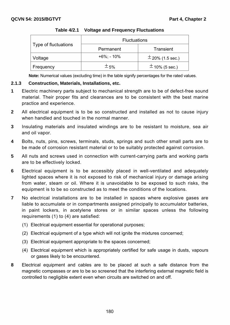
QCVN 54: 2015/BGTVT Part 4, Chapter 2
180
Table 4/2.1 Voltage and Frequency Fluctuations
Type of fluctuations Fluctuations
Permanent Transient
Voltage +6%; - 10% 20% (1.5 sec.)
Frequency 5% 10% (5 sec.)
Note: Numerical values (excluding time) in the table signify percentages for the rated values.
2.1.3 Construction, Materials, Installations, etc.
1 Electric machinery parts subject to mechanical strength are to be of defect-free sound material. Their proper fits and clearances are to be consistent with the best marine practice and experience.
2 All electrical equipment is to be so constructed and installed as not to cause injury when handled and touched in the normal manner.
3 Insulating materials and insulated windings are to be resistant to moisture, sea air and oil vapor.
4 Bolts, nuts, pins, screws, terminals, studs, springs and such other small parts are to be made of corrosion resistant material or to be suitably protected against corrosion.
5 All nuts and screws used in connection with current-carrying parts and working parts are to be effectively locked.
6 Electrical equipment is to be accessibly placed in well-ventilated and adequately lighted spaces where it is not exposed to risk of mechanical injury or damage arising from water, steam or oil. Where it is unavoidable to be exposed to such risks, the equipment is to be so constructed as to meet the conditions of the locations.
7 No electrical installations are to be installed in spaces where explosive gases are liable to accumulate or in compartments assigned principally to accumulator batteries, in paint lockers, in acetylene stores or in similar spaces unless the following requirements (1) to (4) are satisfied:
(1) Electrical equipment essential for operational purposes;
(2) Electrical equipment of a type which will not ignite the mixtures concerned;
(3) Electrical equipment appropriate to the spaces concerned;
(4) Electrical equipment which is appropriately certified for safe usage in dusts, vapours or gases likely to be encountered.
8 Electrical equipment and cables are to be placed at such a safe distance from the magnetic compasses or are to be so screened that the interfering external magnetic field is controlled to negligible extent even when circuits are switched on and off.

Part 4, Chapter 2 QCVN 54: 2015/BGTVT
181
2.1.4 Earthing
1 Non-current-carrying exposed metal parts of electrical equipment which are not intended to be live but which are liable under fault conditions to become live are to be effectively earthed except the following :
(1) They are supplied at a voltage not exceeding 55 V d.c. or 55 V a.c. root mean square between conductors. However, auto-transformers are not to be used for the purpose of achieving this voltage;
(2) They are supplied at a voltage not exceeding 250 V by safety isolating transformers supplying only one consuming device;
(3) They are constructed in accordance with the principle of double isolation.
2 Additional safety means are to be provided for portable electrical apparatus for use in confined or exceptionally damp spaces where particular risks due to conductivity may exist.
3 Where earthing connections are necessary, the earthing conductors are to be of copper or other approved materials, and are to be properly protected against damage, and, where necessary, erosion. The size of the earthing conductors is to be deemed appropriate by VR according to the cross sectional area of the current carrying conductors and installation of the earthing lines.
4 In case where aluminum superstructures are secured to the steel hull of the craft including insulation to prevent galvanic corrosion between these materials, a separate bonding connection is to be provided between the superstructure and the hull which is to be made in such a manner that galvanic corrosion is avoided and points of connection may be readily inspected.
5 For ships whose main structure is made of non-metallic materials the following additional requirements in (1) to (5) are also to be met.
(1) All metal parts of the craft are to be earthed to the sea water, in so far as possible in consideration of galvanic corrosion between dissimilar metals. The earthing of isolated components inside the structure is not generally necessary, except in fuel tanks;
(2) Each pressure refueling point is to be provided with a means of earthing the fuelling equipment to the ship;
(3) Metallic pipes capable of generating electrostatic discharges, due to the flow of liquids and gases are to be bonded so as to be electrically continuous throughout their length and are to be adequately earthed;
(4) Secondary conductors provided for the equalization of static discharges, bonding of equipment, etc. are to have a minimum cross section of 5 mm2 in copper or equivalent surge carrying capacity in aluminum;
(5) The electrical resistance between bonded objects and the basic structure is not to exceed 0.05 . The bonding path is to have sufficient cross-sectional area to carry the maximum current likely to be imposed on it without excessive voltage drop.

QCVN 54: 2015/BGTVT Part 4, Chapter 2
182
2.2 System Design - General
2.2.1 Distribution Systems
1 The following distribution systems are considered as a standard:
(1) Two-wire direct current;
(2) Three-wire direct current (three-wire insulated system or three-wire mid-wire earthed system);
(3) Two-wire, single-phase alternating current;
(4) Three-wire, three-phase alternating current;
(5) Four-wire, three-phase alternating current.
2 Notwithstanding the requirement in -1, a hull return distribution system may be used for the following system.
(1) Impressed current cathodic protection systems for external hull protection;
(2) Limited and locally earthed systems, provided that any possible resulting current does not flow directly through any dangerous spaces;
(3) Insulation monitoring systems provided the circulation current does not exceed 30 mA under any circumstances.
2.2.2 Insulation Monitoring System
When a distribution system, whether primary or secondary, for power, heating or lighting, with no connection to earth is used, a device capable of continuously monitoring the insulation level to earth and of giving an audible or visual indication of abnormally low insulation values is to be provided. For craft with a gross tonnage less than 500, insulation monitoring system may be replaced with earth indicating lamps.
2.2.3 Unbalance of Loads
1 Unbalance of loads between an outer conductor and the middle wire at the switchboards, section boards and distribution boards is not to exceed 15% of the full load current as far as possible.
2 Unbalance of loads on each phase at the switchboards, section boards and distribution boards is not to exceed 15% of the full load current as far as possible.
2.2.4 Diversity Factor
1 Circuits supplying two or more final-subcircuits are to be rated in accordance with the total connected load subject, where justifiable, to the application of a diversity factor.
2 The diversity factor specified in -1 may be applied to the calculation of the cross sectional area of conductors and ratings of switchgears (including circuit breakers and switches) and fuses.
2.2.5 Feeder Circuits

Part 4, Chapter 2 QCVN 54: 2015/BGTVT
183
1 Motors for essential services requiring dual arrangement are to be supplied by individual circuits without the use of common feeders, protective devices and control gears.
2 Auxiliaries in the machinery spaces, cargo gears and ventilating fans are to be independently supplied from switchboards or distribution boards.
3 Ventilating fans for the cargo holds and those for the accommodation spaces are not to be supplied from the common feeder circuits.
4 Lighting circuits and motor circuits are to be arranged to be supplied independently from the switchboards.
5 A final sub-circuit of rating exceeding 15 A is not to supply more than one appliance.
2.2.6 Motor Circuits
A separate final sub-circuit is to be provided, as a rule, for every motor for essential service and for every motor of rating at 1 kW or more.
2.2.7 Lighting Circuits
1 Lighting circuits are to be supplied by final sub-circuits separate from those for heating and power except cabin fans and electrical appliances for domestic use.
2 The number of lighting points supplied by a final sub-circuit of rating 15 A or less is not to exceed:
- 10 for the circuits up to 50 V;
- 14 for the circuits from 51 V up to 130 V;
- 24 for the circuits from 131 V up to 250 V;
- In case where the number of lighting points and total load current are invariable, more than the number of points specified above may be connected to the final sub-circuit, provided that the aggregate load current does not exceed 80% of the rating of protective device in the circuit.
3 In a final sub-circuit of rating not exceeding 10 A for panel lighting and electric signs, where lamp holders are closely grouped, the number of points supplied is unrestricted.
4 In spaces where the main engine or boilers are provided, lighting is to be supplied from at least two circuits and to be so arranged that failure of any one circuit will not leave these spaces in darkness. One of the circuits may be reserve lighting circuit or emergency lighting circuit.
2.2.8 Circuits for Internal Communication Systems and Navigational Aids
1 Essential internal communication and signal systems and navigational aids are to have completely self-sustaining independent circuits for ensuring the perfect maintenance of their functions as far as possible.
2 Cables for communication systems are to be so arranged that no induced interference would be caused.

QCVN 54: 2015/BGTVT Part 4, Chapter 2
184
3 No switch is to be provided for feeder circuits of general alarm devices, except for operating switch. Where circuit breaker is used, a suitable means is to be taken to prevent the breaker from being kept in the "off" position.
2.2.9 Circuits for Radio Installations
Feeder circuits for radio installations and the lighting in the control station of radio installations are to be arranged in accordance with the relevant requirements of Chapter 4 Part 8.
2.2.10 Circuits for Electric Heating and Cooking Equipment
1 Each item of electric heating and cooking equipment is to be connected to a separate final sub-circuit except that up to 10 small electric heaters of aggregate current rating not exceeding 15 A may be connected to single final sub-circuit.
2 Electric heating and cooking equipment are to be controlled by the multipole linked switches mounted in the vicinity of the equipment. However, small electric heaters connected to a final sub-circuit of rating not exceeding 15 A may be controlled by a single-pole switch.
2.2.11 Circuits for Shore Connection
1 Where arrangements are made for the supply of electricity from a source on shore, a connection box is to be installed in a suitable position. In case where shore connection cables can be drawn into a switchboard easily and put into service safely, or, where a shore connection receptacle with a permanently fixed cable is installed and put into service safely, the connection box may be omitted provided the protective devices and checking devices specified in -2 are equipped on the switchboard.
2 The connection box is to contain terminals to facilitate a satisfactory connection and a circuit-breaker or an isolating switch with fuses. A means is to be provided for checking the phase sequence (for three-phase alternating current) or the polarity (for direct current).
3 In case where power is supplied from the three-wire neutral earthed system, an earth terminal is to be provided for connecting the hull to an appropriate earth in addition to those specified in -2.
4 At the connection box a notice is to be provided giving information on the system of supply and nominal voltage (and frequency if a.c.) of the system and the procedure for carrying out the connection.
5 Cables between the connection box and the switchboard are to be permanently fixed and a pilot lamp for source and a switch or a circuit-breaker are to be provided on the switchboard.
2.2.12 Disconnecting Switches of Circuits
1 Power circuits and lighting circuits terminating in cargo holds are to be provided with multipole linked switches situated outside these spaces. Provision is to be made for locking in the off position of the switches or switch boxes for these lighting circuits.
Part 4, Chapter 2 QCVN 54: 2015/BGTVT
185
2 Feeder circuits for the electrical equipment installed in hazardous areas are to be provided with multipole linked isolation switches in a safe space. In addition, the isolation switches are to be clearly labeled to identify the electrical equipment to be connected with.
2.2.13 Remote Stopping of Ventilating Fans and Pumps
1 Remote stopping of ventilating fans and pumps is to comply with the requirements in 5.2.1-2 and 5.2.2-2 through -4 Part 5 Section II QCVN 21: 2015/BGTVT.
2 In case where fuses are used to protect a remote stopping circuit specified in -1 above and is only closed when it operates, consideration is to be given against the fuse element failure.
2.3 System Design - Protection
2.3.1 General
Electrical installations of ships are to be protected against accidental overcurrents including short-circuit. The protective devices are to be capable of continuously serving other circuits as far as possible by breaking a fault circuit and eliminating damage to the system and hazard of fire.
2.3.2 Protection against Overload
1 The over current trip characteristics of circuit-breakers and the fusing characteristics of fuses are to be chosen suitably taking into consideration the thermal capacity of electrical equipment and cables to be protected thereby. Fuses above 200 A are not to be used for overload protection.
2 The ratings or appropriate setting of the overload protection device for each circuit are to be permanently indicated at the location of the protection device, and the current-carrying capacity of each circuit is to be indicated.
3 The overload relays of circuit-breakers for generators and overload protections, except moulded-case circuit breakers, are to be capable of adjusting their current setting and time-delay characteristics.
2.3.3 Protection against Short-circuit
1 The breaking capacity of every protective device is to be not less than the maximum value of the short-circuit current which can flow at the point of installation at the instant of constant separation.
2 The making capacity of every circuit-breaker or switch intended to be capable of being closed, if necessary, on short-circuit, is not to be less than the maximum value of the short-circuit current at the point of installation. On alternating current this maximum value corresponds to the peak value allowing for maximum asymmetry.
3 In case where the rated breaking capacity and/or rated making capacity of short-circuit protection are/is not in compliance with the requirements in -1 and -2, fuses or circuit-breakers having the breaking capacity not less than the prospective short-circuit current are to be provided at the power source side of the foregoing short-circuit protection. Circuit-breakers for the generator are not to be used for this purpose. The circuit-breakers

QCVN 54: 2015/BGTVT Part 4, Chapter 2
186
connected to the load side are not to be excessively damaged and are to be capable of further service in the following cases:
(1) When the short-circuit current is broken by the back-up circuit-breaker or fuse;
(2) When the circuit-breaker connected to the load side is closed on the short-circuit current while the back-up circuit-breaker or fuse breaks the current.
2.3.4 Protection of Circuits
1 Each pole and phase of all insulated circuits except neutral and equalizer circuits are to be provided with short-circuit protection.
2 All circuits liable to be overloaded are to be provided with overload protection as indicated below:
(1) Two-wire d.c. or single-phase a.c. system : at least one line or phase;
(2) Three-wire d.c. system : both outer lines;
(3) Three-phase, three-wire system: at least two phases;
(4) Three-phase, four-wire system: each phase.
3 A fuse, a non-linked switch or a non-linked circuit-breaker is not to be inserted in an earthed conductor and a neutral line.
2.3.5 Protection of Generators
1 Generators are to be protected against short-circuit and over current by a multipole circuit-breaker arranged to open simultaneously all insulated poles, or in the case of generators less than 50 kW not arranged to run in parallel, may be protected by a multipole-linked switch with fuse or a circuit-breaker in each insulated pole. The overload protection is to be suitable to the thermal capacity of generators.
2 For d.c. generators arranged to operate in parallel, in addition to the requirement in -1, an instantaneous reverse-current protection, operating at a fixed value of reverse-current within the limits of 2% to 15% of the rated current of the generator, is to be provided. This requirement, however, does not apply to the reverse-current generated from load side, e.g. cargo winch motors, etc.
3 For a.c. generators arranged to operate in parallel, in addition to the requirement in -1, a reverse-power protection, with time delay, selected and set within the limits of 2% to 15% of the full load to a value fixed in accordance with the characteristics of the prime mover, is to be provided.
2.3.6 Protection of Essential Services
Where generators are operated in parallel and essential machinery is electrically driven, arrangements are to be made to disconnect automatically the excess non-essential loads when the generators are overloaded. If required, this preference tripping may be carried out in one or more stages.
2.3.7 Protection of Feeder Circuits

Part 4, Chapter 2 QCVN 54: 2015/BGTVT
187
1 Supply circuits to section boards, distribution boards, grouped starters and the similar are to be protected against overload and short-circuit by multi-pole circuit-breakers or fuses. In case where the fuses are used, an isolating switch is to be provided at the power source side of the fuses.
2 Each insulated pole of the final sub-circuits is to be protected against short-circuit and overload by a circuit-breaker or fuse. In case where fuses are used, an isolating switch is, as a rule, to be provided at the power source side of the fuses. And for the protection of supply circuits of the steering gears, the requirements in 15.2.7 Part 3 Section II QCVN 21: 2015/BGTVT are to apply.
3 Circuits which supply motors fitted with overload protection may be provided with short-circuit protection only.
4 In case where fuses are used to protect three-phase a.c. motor circuits, consideration is to be given to protection against single phasing.
5 In case where condensers for phase advance are used, overvoltage protective devices are to be installed as required.
2.3.8 Protection of Power and Lighting Transformers
1 The primary circuits of power and lighting transformers are to be protected against short-circuit and overcurrent by multipole circuit-breakers or fuses.
2 When transformers are arranged to operate in parallel, a means of isolation is to be provided on the secondary circuits.
2.3.9 Protection of Electric Motors
1 Motors of rating exceeding 0.5 kW and all motors for essential services, except the motors for steering gears, are to be protected individually against overload. The overload protection for motors for the steering gears is to comply with the requirements in 15.2.7 Part 3 Section II QCVN 21: 2015/BGTVT.
2 The protective devices are to have a delay characteristics to enable the motor to start.
3 For motors for intermittent services, the current setting and the delay are to be chosen in relation to the load factor of the motor.
2.3.10 Protection of Lighting
Lighting circuits are to be protected against short-circuit and overload.
2.3.11 Protection of Meters, Pilot Lamps and Control Circuits
1 Protection is to be provided for voltmeters, voltage coils of measuring instruments, earth indicating devices and pilot lamps together with their connecting leads by means of fuses fitted to each insulating pole. A pilot lamp installed as an integral part of another item of equipment need not be individually protected, provided that any damage of pilot lamp circuit does not cause failures on the supply to essential equipment.
2 Insulated wires for control and instrument circuits directly led from busbars and generator mains are to be protected by fuses at the nearest location to the connecting points.

QCVN 54: 2015/BGTVT Part 4, Chapter 2
188
Insulated wires between the fuses and the connecting points are not to be bunched together with wires for other circuits.
3 Fuses in circuits such as those of automatic voltage regulators where loss of voltage might have serious consequences may be omitted. If omitted, a proper means is to be provided to prevent risk of fire in the unprotected part of the installation.
2.3.12 Protection of Batteries
Accumulator batteries other than engine starting batteries are to be protected against overload and short-circuit with devices placed as near as practicable to the batteries. Emergency batteries supplying essential services may have short-circuit protection only.
2.4 Electrical Equipment and Cables - General
2.4.1 Rotating Machines
Rotating machines are to comply with the requirements in 2.4 Part 4 Section II QCVN 21: 2015/BGTVT.
2.4.2 Transformers for Power and Lighting
Transformers for power and lighting are to comply with the requirements in 2.10 Part 4 Section II QCVN 21: 2015/BGTVT.
2.4.3 Circuit-breakers
Circuit-breakers are to comply with the requirements in 2.6.1 Part 4 Section II QCVN 21: 2015/BGTVT.
2.4.4 Fuses
Fuses are to comply with the requirements in 2.6.2 Part 4 Section II QCVN 21: 2015/BGTVT
2.4.5 Electromagnetic Contactors
Electromagnetic contactors are to comply with the requirements in 2.6.3 Part 4 Section II QCVN 21: 2015/BGTVT.
2.4.6 Semiconductor Converters for Power
Semiconductor converters for power are to comply with the requirements in 2.12 Part 4 Section II QCVN 21: 2015/BGTVT.
2.4.7 Lighting Fittings and Wiring Accessories
Lighting fittings and wiring accessories are respectively to comply with the requirements in 2.13 and 2.14 Part 4 Section II QCVN 21: 2015/BGTVT.
2.4.8 Heating and Cooking Equipment
Part 4, Chapter 2 QCVN 54: 2015/BGTVT
189
Heating and cooking equipment is to comply with the requirements in 4.4.1 Part 5 Section II QCVN 21: 2015/BGTVT.
2.5 Switchboards, Section Boards and Distribution Boards
2.5.1 Location
Switchboards are to be installed in dry places away from the vicinity of steam, water and oil pipes as possible.
2.5.2 Safety Precautions to Operators
1 Switchboards are to be so arranged as to give easy access to each component without danger to personnel.
2 The sides and the rear and, where necessary, the front of switchboards are to be suitably guarded.
3 For voltage between poles, or to earth, exceeding 55 V d.c. or 55 V a.c. root mean square, switchboards are to be of dead front type.
4 Insulated handrails are to be provided on the front and the rear faces of switchboards, and where necessary, insulated mats or gratings are to be provided on the floor of passageway.
5 Sufficient space for operation is to be provided in front of switchboards. Where necessary, space at the rear of switchboards is provided to permit operation and maintenance of disconnecting switches, switches, fuses and other parts, the passageway is to be more than 0.5 m in width.
6 Section boards and distribution boards are to have suitable protective enclosures depending on their location. If they are installed in such a location that they are readily accessible for persons other than those responsible operators, proper protection is to be arranged so that safety can be ensured in normal operation.
2.5.3 Construction and Materials
1 Busbars, circuit-breakers and other electrical appliances of main switchboards are to be so arranged that essential electrical equipment required to be installed in duplicate will not become unserviceable simultaneously by a single fault.
2 Where the main source of electrical power is necessary for propulsion of the ship, the main switchboard is to comply with the following requirements or to be of the performance equivalent thereto.
(1) A generator switchboard is to be provided for each generator, and the switchboards adjoining each other are to be partitioned by the walls of steel or flame-retardant material;
(2) The main busbars are to be subdivided into at least two parts which are to be normally connected by removable links or other approved means. So far as is practicable, the connection of generating sets and other duplicated equipment are to be equally divided between the parts.
3 Cable entries of switchboards are to be so constructed that no ingress of water into the switchboard is permitted along the cables.

QCVN 54: 2015/BGTVT Part 4, Chapter 2
190
4 In case where the supply circuits having different voltages are installed in the same space of a switchboard, a section board or a distribution board, all appliances are to be so arranged that the cables of different rated voltages can be laid without coming to contact with each other within the board.
5 The enclosures are to be of robust construction and their materials used are to be incombustible and non-hygroscopic.
6 Insulating materials are to be durable, flame-retardant and non-hygroscopic.
7 Wiring materials are to conform to the following requirements.
(1) Insulated wires for switchboards are to be those of flame-retardant and non-
hygroscopic having a maximum permissible conductor temperature not less than 75
°C ;
(2) Ducts and straps for wiring are to be of flame-retardant materials;
(3) Insulated wires for control and instrument circuits are not to be bunched together with
wires for main circuits and not to be in the same duct. However, if the rated voltages
and maximum permissible temperatures of conductors are the same each other and
no injurious effects are imposed by the main circuits, this requirement may not be
applied.
8 Except where an isolation switch is provided, circuit breakers are to be such that repairing
and replacing can be made without disconnecting them from the busbar connections and
switching off the power source.
2.5.4 Busbars
1 Busbars are to be of copper or of copper-surrounded aluminum alloy.
2 Busbar connections are to be so made as to inhibit corrosion and oxidization.
3 Busbars and busbar connections are to be so supported as to withstand the
electromagnetic force resulted from short-circuiting.
4 Temperature rises of busbars, connecting conductors and their connections are not to
exceed 45 °C at ambient temperatures of 45 °C in cases where they are carrying full-load
currents. However, in cases where deemed appropriate by VR, these requirements do not
apply.
5 Air clearances (phase-to-phase, pole-to-pole and phase-to-earth) of non-insulated busbars
are not to be less than the values given in Table 4.2.2.

Part 4, Chapter 2 QCVN 54: 2015/BGTVT
191
Table 4/2.2 Minimum Air Clearances for Busbars
Rated voltage (V) Air clearance (mm)
250 or less 15
over 250 to 690 inclusive 20
over 690 to 1,000 inclusive 35
2.5.5 Equalizer
1 The current rating of equalizer connections and equalizer switches is not to be less than a half of the rated full load current of the generator.
2 The current rating of equalizer busbars is not to be less than a half of the rated full-load current of the largest generator in the group.
2.5.6 Measuring Instruments for d.c. Generators
Ship's service d.c. generator panels are at least to be provided with the instruments as given in Table 4.2.3.
Table 4/2.3 Instruments for d.c. Generator Panel
Operation Instrument Number required
2-wire system 3-wire system
Not parallel
Ammeter 1 for each generator (positive pole)
* 2 for each generator (positive and negative poles)
Voltmeter 1 for each generator 1 for eachgenerator (voltage measurement between positive and negative poles or between positive or negative pole and neutral poles)
Parallel
Voltmeter 2 (busbar and each
generator)
2 (voltage measurement between busbar and positive and negative poles of each generator, or between positive pole and neutral pole)
Ammeter 1 for each generator
(positive pole)
* 2 for each generator (in case of compound winding, between equalizer and armature, and in case of shunt winding, for positive and negative poles)
Note:
1. When employed neutral line earthed system, a zero centre ammeter for the earth line is to be added to the number marked with "*" in the above Table.
2. One of the voltmeters is to be capable of measuring shore supply voltage.
3. Where a control panel is provided for automatic control of generators, the instruments in the above table may be installed on the control panel, except that, if the control panel is installed outside engine room, the minimum number of instruments required to carry out single or parallel operation of generators is to be mounted of the switchboard.
4. In case where there are two or more generators which are not operated in parallel, one ammeter and one voltmeter may be permitted provided that one portable voltmeter and one portable ammeter are located on board.
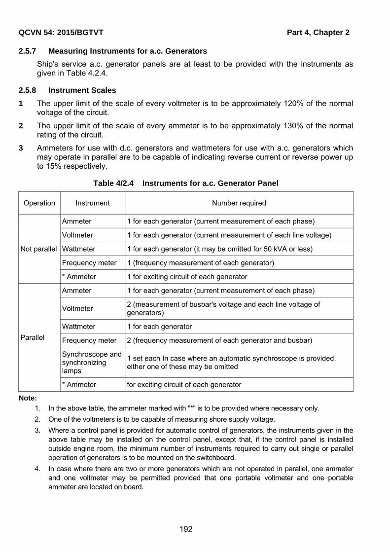
QCVN 54: 2015/BGTVT Part 4, Chapter 2
192
2.5.7 Measuring Instruments for a.c. Generators
Ship's service a.c. generator panels are at least to be provided with the instruments as given in Table 4.2.4.
2.5.8 Instrument Scales
1 The upper limit of the scale of every voltmeter is to be approximately 120% of the normal voltage of the circuit.
2 The upper limit of the scale of every ammeter is to be approximately 130% of the normal rating of the circuit.
3 Ammeters for use with d.c. generators and wattmeters for use with a.c. generators which may operate in parallel are to be capable of indicating reverse current or reverse power up to 15% respectively.
Table 4/2.4 Instruments for a.c. Generator Panel
Operation Instrument Number required
Not parallel
Ammeter 1 for each generator (current measurement of each phase)
Voltmeter 1 for each generator (current measurement of each line voltage)
Wattmeter 1 for each generator (it may be omitted for 50 kVA or less)
Frequency meter 1 (frequency measurement of each generator)
* Ammeter 1 for exciting circuit of each generator
Parallel
Ammeter 1 for each generator (current measurement of each phase)
Voltmeter 2 (measurement of busbar's voltage and each line voltage of generators)
Wattmeter 1 for each generator
Frequency meter 2 (frequency measurement of each generator and busbar)
Synchroscope and synchronizing lamps
1 set each In case where an automatic synchroscope is provided, either one of these may be omitted
* Ammeter for exciting circuit of each generator
Note:
1. In the above table, the ammeter marked with "*" is to be provided where necessary only.
2. One of the voltmeters is to be capable of measuring shore supply voltage.
3. Where a control panel is provided for automatic control of generators, the instruments given in the above table may be installed on the control panel, except that, if the control panel is installed outside engine room, the minimum number of instruments required to carry out single or parallel operation of generators is to be mounted on the switchboard.
4. In case where there are two or more generators which are not operated in parallel, one ammeter and one voltmeter may be permitted provided that one portable voltmeter and one portable ammeter are located on board.

Part 4, Chapter 2 QCVN 54: 2015/BGTVT
193
2.5.9 Transformers for Instruments
The secondary windings of transformers for instruments are to be earthed.
2.6 Controlgears for Motors
2.6.1 Controlgears for Motors
1 Controlgears for motors are to be durably constructed and provided with efficient means of starting, stopping, reversing and speed controlling of motors together with essential safety devices.
2 Controlgears for motors are to be provided with protective enclosures suitable for their location and to allow safe operation for the personnel.
3 All wearing parts of controlgears are to be readily replaceable and accessible for inspection and maintenance.
4 Motors above 0.5 kW are to be provided with the controlgears complying with the requirements in -1, -2 and -3 and in the following:
(1) A means is to be provided to prevent undesired restarting after stoppage due to low voltage or complete loss of voltage. This requirement does not apply to motors, continuous availability of which is essential to the safety of the craft and to motors with automatic operation.
(2) A primary means of isolation is to be provided so that all voltages may be cut off from the motor, except where a means of isolation (that provided at the switchboard, the section board, the distribution board, etc.) is adjacent to the motor.
(3) A means for automatic disconnection of the power supply is to be provided in the event of excess current due to mechanical overloading of the motor. This requirement does not apply to motors for steering gears.
5 In case where the primary means of isolation is remote from the motor, either of the following means or the equivalent is to be provided:
(1) An additional means of isolation fitted adjacent to the motor is to be provided.
(2) Provision is made for locking the primary means of isolation in the "off" position.
6 When fuses are used to protect three-phase a.c. motor circuits, consideration is to be given to protect against single phasing.
7 Running indicators and overload alarms for motors for steering gears are to comply with the requirements in 15.2.7 Part 3 Section II QCVN 21: 2015/BGTVT.
2.7 Cables
2.7.1 General
Cables are to comply with IEC 60092 or equivalent thereto. Installation of cables is to comply with the requirements in this 2.7.

QCVN 54: 2015/BGTVT Part 4, Chapter 2
194
2.7.2 Installation of Cables
1 Cables are to have a construction as to meet the conditions of the locations. Cables fitted in spaces where they are likely to suffer from mechanical damages are to be suitably protected by means of, e.g., effective metal casings.
2 Cable runs are to be, as far as possible, straight and accessible.
3 The installation of cables across expansion joints in the craft's structure is to be avoided as far as possible. Where such installation is unavoidable, a loop of cable of length proportional to the expansion of the joint is to be provided. The internal radius of the loop is to be at least 12 times the external diameter of the cable.
4 Where a duplicate supply is required, the two cables are to follow different routes which are to be as far apart as practicable.
5 Cables having insulating materials with different maximum-rated conductor temperatures are not to be bunched together, or, where such bunching is unavoidable, the cables are to be operated so that no cable may reach a temperature higher than that permitted for the lowest temperature-rated cable in the group.
6 Cables having a protective covering which may damage the covering of other cables are not to be bunched together with those other cables.
7 When installing cables, the minimum inside radius of bend is to be in accordance with the following:
(1) Armoured rubber insulated and PVC insulated cables: 6d;
(2) Unarmoured rubber insulated and PVC insulated cables:
- 4d (d ≤ 25 mm);
- 6d (d > 25 mm).
(3) Mineral insulated cables: 6d.
Note: d is overall diameter of the finished cables.
8 Intrinsically safe circuits are to be installed complying with the followings:
(1) The cables for intrinsically safe circuits associated with intrinsically safe type electrical equipment are to be of exclusive use, being installed separately from cables for general circuits.
(2) Intrinsically safe circuits associated with different intrinsically safe type electrical equipment are, as a rule, to be wired individually using different cables. Where it is necessary to use a multi-core cable in common, a cable which has shields by each core or each pair of cores is to be used, having such shields earthed effectively. However, intrinsically safe circuits associated with category "ia" intrinsically safe type electrical equipment is not to be contained in a cable associated with category "ib" intrinsically safe type electrical equipment.

Part 4, Chapter 2 QCVN 54: 2015/BGTVT
195
9 Metallic coverings of cables are to be effectively earthed at both ends, except that in final sub-circuits earthing may be at the supply end only. This does not necessarily apply to instrumentation cables where single point earthing may be desirable for technical reasons.
10 Effective means are to be taken to ensure that all metallic coverings of cables are made electrically continuous throughout their length.
11 Cables and wires are to be so supported and secured that they may not be injured by chafing or other mechanical damage.
12 Penetration of bulkheads and decks, which are required to have some degree of strength and tightness, is to be so carried out by means of cable glands or boxes as to ensure that the strength and tightness are not impaired.
13 Where cables pass through non-watertight bulkheads or structures, bushings or other suitable means are to be provided in order to avoid damage to cables. If the thickness of the steel is sufficient (≥ 6 mm) and there is no risk of damage to cables, adequately rounded edges may be accepted as the equivalent of bushing.
14 The choice of the materials for glands and bushings is to be such that there is no risk of corrosion.
15 Penetration through bulkheads and decks, which are to have some degree of fire integrity is to be so effected as to ensure that the fire integrity is not impaired.
2.7.3 Terminals, Joints and Branches of Cables
1 Cables are to be jointed by terminals. However, in cases where deemed appropriate by VR, these requirements do not apply. Soldering fluxes containing corrosive substances are not to be used.
2 Terminals are to have sufficient contacting surface and pressure.
3 The length of soldered parts of copper tube terminals and other terminals is not to be less than 1.5 times the diameter of conductors.
4 Cables not having a moisture-resistant insulation (e.g., mineral insulation) are to have their ends effectively sealed against ingress of moisture.
5 Terminals and joints (including branches) of all cables are to be so made as to retain the original electrical, mechanical, flame-retardant and, where necessary, fire-resisting properties of the cable.
6 Terminals and conductors are to be of dimensions adequate for the cable rating.
2.7.4 Precaution against Fire
All cables for essential services are to be so far as practicable routed clear of machinery spaces of Category A and their casings, galleys, laundries and other high fire risk areas.
2.7.5 Cables in Hazardous Areas
Where cables which are installed in hazardous areas introduce the risk of fire or explosion in the event of an electrical fault in such areas, proper protections against such risks are to be provided.

QCVN 54: 2015/BGTVT Part 4, Chapter 2
196
2.8 Accumulator Batteries
2.8.1 General
1 The requirements in this 2.8.1 apply to permanently installed secondary batteries of vented type. A vented type secondary battery means one in which the electrolyte can be replaced and which may release gas while operating on charge and overcharge.
2 Proposals for the use of other types of secondary batteries are to be as deemed appropriate by VR.
3 Accumulator batteries are to have performance suitable for intended services.
2.8.2 Construction
Cells of all batteries are to be so constructed and secured as to prevent spilling of the electrolyte due to craft's motions and to prevent emission of acid or alkaline spray.
2.8.3 Location
1 Alkaline batteries and lead acid batteries are not to be installed in the same compartment.
2 Large batteries are to be installed in compartment assigned to them only. They may be installed in a box on deck if adequately ventilated and provided with means to prevent ingress of water.
3 Engine starting batteries are to be located as close as practicable to the engine(s) served.
4 Batteries are not to be placed in the living quarters.
2.8.4 Installation Procedures and Protection of Corrosion
1 Batteries are to be arranged to permit ready access for replacing, inspection, testing, replenishing and cleaning.
2 Cells or crates are to be placed on non-absorbent isolating supports. They are to be fitted to prevent any movement due to craft's motions.
3 In case where acid is used as the electrolyte, a tray of acid resisting materials is to be provided below the cells unless the deck below is similarly protected.
4 The interior of the battery compartment including the shelves is to be coated with corrosion-resistant paint.
5 The interior of ventilating ducts and impellers of ventilating fans are to be coated with corrosion-resistant paint unless ducts and fans are made of corrosion-resistant material.
2.8.5 Ventilation
1 Battery compartments are to be adequately ventilated by an independent ventilating system.
2 In case where natural ventilation is employed, the ventilation ducts are to be run directly from the top of the battery compartment to the open air above, with no part of the ducts more than 45° from the vertical.

Part 4, Chapter 2 QCVN 54: 2015/BGTVT
197
3 If natural ventilation is impracticable, mechanical exhaust-ventilation is to be provided. The electric motors for the ventilation fans are not to be placed inside the ducts. Ventilating fans are to be so constructed and to be of such a material as to render sparking impossible in the event of the impeller touching the fan casing.
2.8.6 Electrical Installations
1 Switches, fuses and other electrical installations liable to cause an arc are not to be installed in battery compartments.
2 Lighting fittings provided within battery compartments are to be suitable for use in explosive atmosphere classified into gases and vapors group IIC and temperature class T1 as specified in IEC 60079, or equivalent thereto.
3 Cables other than those for batteries and electrical installations specified in -2 are, as a rule, not to be installed in battery compartments except where installation in other locations is impracticable.
2.8.7 Charging Facilities
1 Suitable charging facilities are to be provided. Battery charging facilities by means of d.c. generator and series resister are to be provided with protection against reversal of current when the charging voltage is 20% of the line voltage or higher.
2 For floating service or for any other conditions where the load is connected to the battery while it is on charge, the maximum battery voltage under any conditions of charge is not to exceed the safe value of any connected apparatus. A voltage regulator or other means of voltage control may be provided for this purpose.
2.9 Explosion-protected Electrical Equipment
2.9.1 General
1 Explosion-protected electrical equipment is to comply with the requirements in 2.16 Part 4 Section II QCVN 21: 2015/BGTVT.
2 Explosion-protected electrical equipment is to be provided with a certificate which is deemed appropriate by VR.
2.10 High Voltage Electrical Installations
2.10.1 High Voltage Electrical Installations
High voltage electrical installations are to comply with the requirements in 2.17 Part 4 Section II QCVN 21: 2015/BGTVT.
2.11 Tests after installation on Board
2.11.1 Insulation Resistance Test
1 Each circuit of power and lighting is to have insulation resistances not less than the values in Table 4.2.5 between conductors and between each conductor and earth.
2 Insulation resistances of internal communication circuits are to comply with the following requirements (1) to (3) :

QCVN 54: 2015/BGTVT Part 4, Chapter 2
198
Table 4/2.5 Minimum Insulation Resistance
Rated voltage Un (V) Minimum test voltage
(V) Minimum insulation
resistance (MΩ)
Un ≤ 250
250 < Un ≤ 1,000
1,000 < Un ≤ 7,200
7,200 < Un
2 x Un
500
1,000
5,000
1
1
Un/1,000 +1
Un/1,000 + 1
Note: During the above test, any or all electric heaters, small appliances and the like connected thereto may be disconnected from the circuit..
(1) Each circuit of 100 V and above is to have an insulation resistance not less than 1 M between conductors and between each conductor and earth.
(2) For circuits below 100 V, the insulation resistance is to be at least 1/3 M .
(3) During the test for (1) and (2), any or all appliances connected thereto may be disconnected from the circuit.

Part 4, Chapter 2 QCVN 54: 2015/BGTVT
199
2.11.2 Performance Tests
1 All electrical equipment is to be examined under normal conditions to demonstrate its proper operation with no harmful vibration nor temperature rise.
2 Among the examinations specified in -1, the following tests concerning generators and switchboards are to be included.
(1) The operation test of overspeed trip and other safety devices of generators;
(2) The voltage regulation test and the parallel operation test of generators.

QCVN 54: 2015/BGTVT Part 4, Chapter 3
200
CHAPTER 3 DESIGN OF INSTALLATIONS
3.1 General
3.1.1 General
This Chapter specifies the requirements for the design of installations of main source of electrical power, emergency source of electrical power and other electrical installations on board craft.
3.1.2 Design and Construction
1 Electrical installations are to comply with the following:
(1) All electrical auxiliary services necessary for maintaining the craft in normal operational and habitable conditions and other electrical services as deemed necessary by VR will be ensured without recource to the reserve or emergency source of electrical power;
(2) Electrical services essential for safety will be ensured under various emergency conditions; and
(3) The safety of passengers, crew and craft from electrical hazards will be ensured.
3.2 Source of Electrical Power and Lighting Systems
3.2.1 Main Source of Electrical Power in Cargo Craft
1 A main source of electrical power of sufficient capacity to supply all those services specified in 3.1.2(1) is to be provided.
2 The arrangements of the ship's main source of electrical power are to be such that the services referred to the requirement in 3.1.2(1) can be maintained regardless of the speed and direction of the propulsion machinery or shafting.
3.2.2 Main Source of Electrical Power in Passenger Craft
1 A main source of electrical power of sufficient capacity to supply all those services specified in 3.1.2(1) is to be provided. This main source of electrical power is to consist of at least two generating sets.
2 The capacity of these generating sets is to be such that in the event of any one generating set being stopped it will still be possible to supply those services necessary to provide normal operational conditions of propulsion and safety devices.
3 The arrangements of the ship's main source of electrical power are to be such that the services referred to the requirement in 3.1.2(1) can be maintained regardless of the speed and direction of the propulsion machinery or shafting.
4 The generating sets are to be such as to ensure that with any one generator or its primary source of power out of operation, the remaining generating sets are to be capable of providing the electrical services necessary to start the main propulsion plant.

Part 4, Chapter 3 QCVN 54: 2015/BGTVT
201
5 Where transformers constitute an essential part of the electrical supply system required by 3.2.2, at least 2 transformers are to be provided or equivalent arrangement is to be made.
3.2.3 Lighting Systems
1 A main electric lighting system supplied from the main source of electrical power is to be provided in spaces or compartments where passengers and crew use and normally work on duty.
2 Reserve lighting providing sufficient illumination necessary for the safety is to be provided at/in the following spaces. Additionally, for passenger crafts, emergency electric lighting systems are to be provided.
(1) Every muster and embarkation station, and over sides;
(2) All alleyways, stairways and exits, personnel lift cars and personnel lift trunks;
(3) Machinery spaces and a location of the reserve source of electrical power;
(4) Main engine control stations;
(5) Location of steering gear;
(6) Location of emergency fire pump;
(7) Stowage positions for fireman's outfits.
3.2.4 Reserve Source of Electrical Power in Cargo Craft
1 A reserve source of electrical power capable of supplying simultaneously the services listed in the following for 4 hours (for continuous 30 minutes for intermittent operation services of signals and alarms) is to be provided:
(1) Reserve lighting specified in 3.2.3-2;
(2) Navigation lights and other lights, and sound signals;
(3) All internal communication equipment as required in an emergency;
(4) Fire detection and alarm systems;
(5) Radio equipments;
(6) Ship's whistle (in case of electrical whistle).
3.2.5 Emergency Source of Electrical Power in Passenger Craft
1 A self-contained emergency source of electrical power is to be provided, capable of automatically supplying simultaneously the services listed in the following (1) to (8) for 5 hours (for continuous 30 minutes for intermittent operation services of signals and alarms) in case of failure of the main source. Additionally, the emergency source of electrical power on passenger craft is to be in accordance with requirements in 3.2.6 to 3.2.9
(1) Emergency lighting specified in 3.2.2-2;
(2) Illuminating passenger spaces;
(3) For ro-ro passenger craft, a portable rechargeable battery operated lamp is to be provided in every crew space alleyway, recreational space and every working space which is normally occupied unless supplementary emergency lighting is provided.;

QCVN 54: 2015/BGTVT Part 4, Chapter 3
202
(4) Navigation lights and other lights, and sound signals;
(5) All internal communication equipment as required in an emergency;
(6) Radio equipments;
(7) Fire detection and alarm systems;
(8) Ship's whistle (in case of electrical whistle).
Emergency source of electrical power may be either a generator or an accumulator battery.
2 The emergency source of electrical power, associated transforming equipment, the emergency switchboard and the emergency lighting switchboard are to be located above the uppermost continuous deck and are to be readily accessible from the open deck. They are not to be located forward of the collision bulkhead, except where permitted by VR in exceptional circumstances.
3 The location of the emergency source of electrical power, associated transforming equipment and the emergency lighting switchboard are to be such as to ensure to the satisfaction of VR that a fire or other casualty in the space containing the main source of electrical power, associated transforming equipment and the main switchboard will not interfere with the supply, control and distribution of emergency electrical power.
3.2.6 Kind and performance of emergency source of electrical power
1 Where the emergency source of electrical power is a generator, it is to comply with the following:
(1) The emergency generator is to be driven by a suitable primemover with a supply of fuel, having a flashpoint (closed cup test) of not less than 43 °C;
(2) The emergency generator is to be started automatically upon failure of the main source of electrical power supply, and then automatically connected to the emergency switchboard to quickly supply power for those services specified in 3.2.5-1 and practicable subject to a maximum of 45 seconds. Where this requirement is not meet, the consideration will be made by VR on a case by case basis.
2 Where the emergency source of electrical power is an accumulator battery it is to be capable of:
(1) Carrying the emergency electrical load without recharging while maintaining the voltage of the battery throughout the discharge period within ±12% above or below its nominal voltage;
(2) Automatically connecting to the emergency switchboard in the event of failure of the main source of electrical power.
3.2.7 Location of emergency source of electrical power
1 The emergency switchboard is to be installed as near as is practicable to the emergency source of electrical power.
2 Where the emergency source of electrical power is a generator, the emergency switchboard is to be located in the same space unless the operation of the emergency switchboard would thereby be impaired.

Part 4, Chapter 3 QCVN 54: 2015/BGTVT
203
3 No accumulator battery is to be installed in the same space as the emergency switchboard.
4 An indicator is to be mounted in a suitable place on the main switchboard or in the machinery control room to indicate when the batteries constituting the emergency source of electrical power are being discharged.
5 An interconnector feeder connecting the emergency switchboard and the main switchboard is to be:
(1) Adequately protected at the main switchboard against overload and short circuit;
(2) Disconnected automatically at the emergency switchboard upon failure of the main source of electrical power;
(3) Protected at the emergency switchboard at least against short circuit where the system is arranged for feedback operation. In addition, the emergency switchboard is to be supplied during normal operation from the main switchboard.
6 Arrangements are to be made where necessary to disconnect automatically non-emergency circuits from the emergency switchboard to ensure that electrical power shall be available automatically to the emergency circuits.
3.2.8 Provision for the testing of emergency source of electrical power
Emergency electrical system is to be provided with measures for periodic testing. The periodic testing is to include the testing of automatic starting arrangements.
3.2.9 Starting arrangement for emergency generating sets
Starting arrangement for emergency generating sets is to comply with requirements in 3.4 Part 4 Section II QCVN 21: 2015/BGTVT.
3.3 Navigation Lights, Other Lights, Internal Signals, etc.
3.3.1 Navigation Lights
1 Navigation lights are to be connected separately to the navigation light indicator panel.
2 Each navigation light is to be controlled and protected in each insulated pole by a switch with fuses or a circuit breaker fitted on the navigation light indicator panel.
3 On cargo craft, the navigation light indicator panel is to be power supplied by a separate circuit from the main switchboard and the reserve source of electrical power or the lighting distribution panel provided on the navigation bridge (limited to the case where two or more generating sets are provided). However, in cargo craft with a gross tonnage less than 500, only one circuit from the main switchboard supplied from the main source of electrical power and the reserve source of electrical power may be accepted.
4 Switches and fuses are not to be provided on the feeder circuits of navigation lights, except the switchboards and indicator panel.
5 The navigation light indicator panel is to be placed in an accessible position on the navigation bridge.
3.3.2 Not Under Command Lights, Anchor Lights and Signal Lights
QCVN 54: 2015/BGTVT Part 4, Chapter 3
204
Not under command lights, anchor lights and signal lights are to be power supplied from both main source of electrical power and reserve source of electrical power.
3.3.3 General Emergency Alarm Systems
General emergency alarm systems are to be power supplied from both main source of electrical power and reserve source of electrical power.
3.4 Lightning Conductors
3.4.1 General
Lightning conductors are to be fitted on each mast of ships having non metallic masts or topmasts.
3.4.2 Construction
1 Lightning conductors are to be composed of continuous copper tape or rope having a section not less than 75 mm2 which is riveted with copper rivets or fastened with copper clamps to a suitable copper spike not less than 12 mm in diameter, projecting at least 150 mm above the top of the mast. At the lower end, this copper tape or rope is to be securely earthed to the sea water.
2 Lightning conductors are to be run as straight as possible, and sharp bends in the conductors are to be avoided. All clamps used are to be of brass or copper, preferably of the serrated contact type, and effectively locked. No connection is to be dependent on a soldered joint.
3 The resistance of lightning conductor between the mast top and the point on the earth plate or hull is not to exceed 0.02 Ω.
Part 4, Chapter 3 QCVN 54: 2015/BGTVT
205
CHAPTER 4 ADDITIONAL REQUIREMENTS FOR CRAFT
CARRYING SPECIAL CARGOES
4.1 Enclosed Cargo Holds for Carrying motor vehicles with Fuel in Their Tanks for Their Own Propulsion and Enclosed Compartments adjoining the Cargo Holds, etc.
4.1.1 Electrical Installation in Enclosed Cargo Holds, etc.
1 Electrical installations in enclosed cargo holds, etc., for carrying motor vehicles with fuel in their tanks are to comply with the requirements in this 4.1.1, in addition to the requirements in other relevant chapters in this Part.
2 Electrical installations are to be of a type suitable for use in explosive gas atmosphere concerned.
3 Electrical equipment installed above a height of 450 mm from the deck or from each platform for vehicles may be of a type so enclosed and protected as to prevent the escape of sparks as an alternative of the electrical equipment specified in -2.
In this case, such electrical equipment are to be installed so that they can be operated only when ventilation system so designed as to provide continuous ventilation of the cargo holds at the rate of at least 10 air changes per hour is in operation whenever motor vehicles are on board. The platforms with openings of sufficient size permitting penetration of petrol gases downwards may not be regarded as the platforms in the application of this requirement.
4 Electrical installations in exhaust ventilation ducts for a cargo hold are to be of a type approved by VR for use in explosive gas atmosphere concerned.
5 As a rule, no portable electrical appliances are to be located in the cargo holds. Where it is unavoidable to locate the appliances in the holds, they are subject to the approval of Society.
6 Fire detection system, gas detection system and the like which are installed in enclosed cargo holds, etc. are to be of explosion-protected type as deemed appropriate by VR.
7 All electrical circuits terminating in enclosed cargo holds, etc. are to be provided with multipole linked isolating switches situated outside the cargo holds and accessible only to authorized personnel. Provision is to be made for isolation, for locking in the off position of the means of control of such circuits. However, this requirement does not apply to safety devices such as fire or gas detectors.
4.1.2 Electrical Equipment in Enclosed Compartments Adjoining Enclosed Cargo Holds
For the electrical equipment in the compartments adjoining cargo holds and having openings such non-gastight door, hatch, scuttle and the like in their bulkheads decks, requirements in 4.1.1 are generally to be applied.

QCVN 54: 2015/BGTVT Part 4, Chapter 4
206
4.2 Special Requirements for Craft Carrying Dangerous Goods
4.2.1 General
Electrical installations for craft carrying dangerous goods are to comply with the requirements in Chapter 19 Part 5 Section II QCVN 21: 2015/BGTVT as well as the relevant requirements in this Part.

Part 4, Chapter 5 QCVN 54: 2015/BGTVT
207
CHAPTER 5 ADDITIONAL REQUIREMENTS FOR ELECTRIC PROPULSION PLANTS
5.1 General
5.1.1 General
Electrical installations for electric propulsion craft are to comply with the requirements in Chapter 5 Part 4 Section II QCVN 21: 2015/BGTVT as well as relevant requirements in this Part.

Part 5, Chapter 1 QCVN 54: 2015/BGTVT
209
PART 5 FIRE PROTECTION, DETECTION, EXTINCTION AND MEANS OF ESCAPE
CHAPTER 1 GENERAL
1.1 General
1.1.1 Application
1 The requirements in this Part apply only to craft which are not engaged in international voyage and are for restricted service.
2 A craft other than the craft specified in -1 above is to be in accordance with the requirements in Chapter 7 - Fire Safety of IMO Resolution MSC.97(73) THE INTERNATIONAL CODE OF SAFETY FOR HIGH SPEED CRAFT, as may be amended.
1.1.2 General Requirements
1 The following basic principles underlay the provisions in this Part and are embodied therein as appropriate, having regard to the category and operating conditions of craft and the potential fire hazard involved:
(1) Prevention of any fire;
(2) Detection of any fire in the space of origin;
(3) Containment of any fire in the space of origin;
(4) Extinction of any fire in the space of origin;
(5) Protection of means of escape and access for fire fighting;
(6) Immediate availability of fire-extinguishing appliances.
1.1.3 General Requirements
1 The requirements in this Part are subject to the following general requirements that:
(1) No enclosed sleeping births for passengers and crews are provided. Enclosed sleeping births mean spaces which are used for living spaces isolated by walls, doors and/or curtains, and which behaviors of passengers or crews inside can not be watched by crew on duty regardless of the existence of bed, floor area or capacity;
(2) In addition to the requirements in this Part, craft which intends to carry dangerous goods is to be complied with the requirements in Chapter 19 Part 5 Section II QCVN 21: 2015/BGTVT. However, cargo craft of less than 500 gross tonnage or for restricted service need not comply with the requirements in 1.2.2, 1.2.3, 10.2.1-4(4), 10.8.1 and 10.9.1 Part 5 Section II QCVN 21: 2015/BGTVT.
(3) Enclosed sleeping births specified in (1) above may be allowed to be arranged provided that doors are to be fitted with no locking devices and the following requirements in (a) and (b) are to be met:

QCVN 54: 2015/BGTVT Part 5, Chương 1
210
(a) A fixed fire detection and fire alarm system complying with Chapter 29 Part 5 Section II QCVN 21: 2015/BGTVT is to be installed in any enclosed sleeping births. However, where a compartment is divided into some small personal enclosed sleeping births by curtains, the requirement of the installation of a fixed fire detection and fire alarm system may be decided individually based upon a compartment having such small births;
(b) Two means of escape from enclosed sleeping births are, in principle, to be provided.
1.1.4 Equivalency
Alternative construction, equipment, arrangement and materials will be accepted by VR, provided that VR is satisfied that such construction, equipment, arrangement and materials are equivalent to those required in this Part.
1.2 Definitions
1.2.1 Application
The definitions of terms which appear in this Part are to be as specified in from 1.2.2 to 1.2.8 below, unless otherwise specified elsewhere:
1.2.2 Fire-Resisting Divisions
1 Fire-resisting divisions are those divisions formed by bulkheads and decks which comply with the following:
(1) They are to be constructed of non-combustible or fire-restricting materials which by insulation or inherent fire-resisting properties satisfy the requirements of following (2) to (6);
(2) They are to be suitably stiffened;
(3) They are to be so constructed as to be capable of preventing the passage of smoke and flame up to the end of the appropriate fire protection time;
(4) Where required, they are to maintain load-carrying capabilities up to the end of the appropriate fire protection time.
(5) They are to have thermal properties such that the average temperature on the unexposed side will not rise more than 139 °C above the original temperature, nor will the temperature, at any one point, including any joint, rise more than 180 °C above the original temperature during the appropriate fire protection time;
(6) A test of a prototype bulkhead or deck in accordance with the test procedures deemed as appropriate by VR, are to be required to ensure that it meets the above requirements.
1.2.3 Fire-Restricting Materials
1 Fire-restricting materials are those materials which have the properties specified in (1) to (4) below, this being ensured in accordance with the test procedures deemed as appropriate by VR:

Part 5, Chapter 1 QCVN 54: 2015/BGTVT
211
(1) They are to have low flame-spread characteristics;
(2) Limit heat flux, due regard being paid to the risk of ignition of furniture in the compartment;
(3) Limited rate of heat release, due regard being paid to the risk of spread of fire to an adjacent compartment;
(4) Gas and smoke are not to be emitted in quantities that could be dangerous to the occupants of the craft.
1.2.4 Non-Combustible Material
Non-combustible material is a material which neither burns nor gives off flammable
vapours in sufficient quantity for self-ignition when heated to approximately 750 °C , this
being ensured in accordance with the test procedures deemed as appropriate by VR.
1.2.5 Standard Fire Test
A standard fire test is one in which specimens of the relevant bulkheads, decks or other constructions are exposed in a test furnace by specified test method which is considered appropriate by VR.
1.2.6 Other Equivalent Materials
Where the words steel or other equivalent materials occur, other equivalent materials means any non-combustible material which, by itself or due to insulation provided, has structural and integrity properties equivalent to steel at the end of the applicable exposure to the standard fire test (e.g., aluminum alloy with appropriate insulation).
1.2.7 Low Flame-Spread
Low flame-spread means that the surface thus described will adequately restrict the spread of flame, this being determined by an established test procedure which is considered appropriate by VR.
1.2.8 Smoke-Tight
Smoke-tight or capable of preventing the passage of smoke means that a division made of non-combustible or fire-restricting materials is capable of preventing the passage of smoke.
1.3 Local Fire
Materials which comply with the requirements in 1.2.3-1(2) may be used as surface materials on bulkheads, wall, and ceiling linings including their supporting structure as considered necessary.

QCVN 54: 2015/BGTVT Part 5, Chapter 2
212
CHAPTER 2 FIRE PROTECTION
2.1 Classification of Space Use
2.1.1 Classification of Space Use
1 For the purposes of classification of space use in accordance with fire hazard risks, the following grouping should apply:
(1) Category A: Areas of major fire hazard
- Machinery spaces;
- Open vehicle spaces;
- Spaces containing dangerous goods;
- Special category spaces;
- Store-rooms containing flammable liquids;
- Galley.
(2) Category B: Areas of moderate fire hazard
- Auxiliary machinery spaces;
- Bond stores containing packaged beverages with alcohol content not exceeding 24% by volume;
- Crew accommodations;
- Service spaces.
(3) Category C: Areas of minor fire hazard
- Auxiliary machinery spaces having little or no fire risk;
- Cargo spaces;
- Fuel tank compartments including fuel oil tanks (however, small fuel oil tanks having capacity of 100 litters or below may be deemed as a part of fuel oil piping system);
- Public spaces;
- Tanks, voids and areas of little or no fire risk.
(4) Category D: Control stations
- Those spaces in which the craft's radio or navigating equipment or the emergency source of power and emergency switchboard are located, or where the fire recording or fire control equipment is centralized, or where other functions essential to the safe operation of the craft such as propulsion control, public address, stabilization systems, etc., are located.
(5) Category E: Evacuation stations
- External stairs and open decks used for escape routes;
- Muster stations, internal and external;

Part 5, Chapter 2 QCVN 54: 2015/BGTVT
213
- Open deck spaces and enclosed promenades forming lifeboat and liferaft embarkation and lowering stations;
- The craft's side to the waterline in the lightest seagoing condition, superstructure and deckhouse sides situated below and adjacent to the liferaft's and evacuation slide's embarkation areas.
(6) Category F: Open spaces
- Open spaces locations other than evacuation stations and external escape routes and control stations.
2.1.2 Treatment of Space
1 If a space is divided by partial bulkheads into two (or more) smaller areas such that they form enclosed spaces, then the enclosed spaces are to be surrounded by bulkheads and decks in accordance with Table 5/2.1, as applicable. However, if the separating bulkheads of such spaces are at least 30% open, then the spaces may be considered as the same space.
2 Cabinets having a deck area of less than 2 m2 may be accepted as part of the space they serve, provided they have open ventilation to the space and do not contain any material or equipment that could be a fire risk.
3 Where a space has the special characteristics of two or more space groupings, the structural fire protection time of the divisions are to be the highest for the space groupings concerned.
2.1.3 Insulation of Deck or Bulkhead
1 To prevent heat transmission at intersections and terminal points, the insulation of the
deck or bulkhead is to be carried past the intersection or terminal point for a distance of at
least 450 mm in the case of steel or aluminum structures (refer to Fig. 5/2.1 and Fig.
5/2.2).
2 If a space is divided by a deck or bulkhead and the fire insulation required for each space
is different, the insulation with the higher structural fire protection time is to continue on the
deck or bulkhead with the insulation of the lesser structural fire protection time for a
distance of at least 450 mm beyond the boundary between the spaces.
3 Where the lower part of the fire insulation has to be cut for drainage, the construction is to
be in accordance with the structural details shown in Fig. 5/2.3.

QCVN 54: 2015/BGTVT Part 5, Chapter 2
214
Fig. 5/2.1 Fire insulation for framing structures
2.2 Construction
2.2.1 Construction
1 The hull, superstructure, structural bulkheads, decks, deckhouses and pillars are to be
constructed of approved non-combustible materials having adequate structural properties.
When the materials other than non-combustible materials are used for these structures,
such materials are to be of appropriate fire-restricting materials approved by VR.
2 The structural fire protection times for separating bulkheads and decks specified in 2.3 in
this Chapter are to be in accordance with Table 5/2.1.
3 In using Table 5/2.1, it is to be noted that the title of each category is intended to be typical
rather than restricted. For determining the appropriate fire integrity standards to be applied
to boundaries between adjacent spaces, where there is doubt as to their classification for
the purpose of this section, they are to be treated as spaces within the relevant category
having the most stringent boundary requirement.
Fig. 5/2.2 Fire insulation for deck, bulkhead
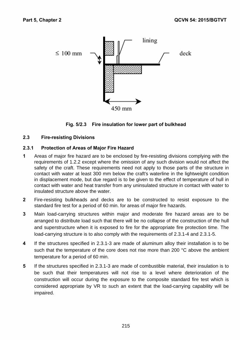
Part 5, Chapter 2 QCVN 54: 2015/BGTVT
215
Fig. 5/2.3 Fire insulation for lower part of bulkhead
2.3 Fire-resisting Divisions
2.3.1 Protection of Areas of Major Fire Hazard
1 Areas of major fire hazard are to be enclosed by fire-resisting divisions complying with the requirements of 1.2.2 except where the omission of any such division would not affect the safety of the craft. These requirements need not apply to those parts of the structure in contact with water at least 300 mm below the craft's waterline in the lightweight condition in displacement mode, but due regard is to be given to the effect of temperature of hull in contact with water and heat transfer from any uninsulated structure in contact with water to insulated structure above the water.
2 Fire-resisting bulkheads and decks are to be constructed to resist exposure to the standard fire test for a period of 60 min. for areas of major fire hazards.
3 Main load-carrying structures within major and moderate fire hazard areas are to be arranged to distribute load such that there will be no collapse of the construction of the hull and superstructure when it is exposed to fire for the appropriate fire protection time. The load-carrying structure is to also comply with the requirements of 2.3.1-4 and 2.3.1-5.
4 If the structures specified in 2.3.1-3 are made of aluminum alloy their installation is to be such that the temperature of the core does not rise more than 200 °C above the ambient temperature for a period of 60 min.
5 If the structures specified in 2.3.1-3 are made of combustible material, their insulation is to be such that their temperatures will not rise to a level where deterioration of the construction will occur during the exposure to the composite standard fire test which is considered appropriate by VR to such an extent that the load-carrying capability will be impaired.
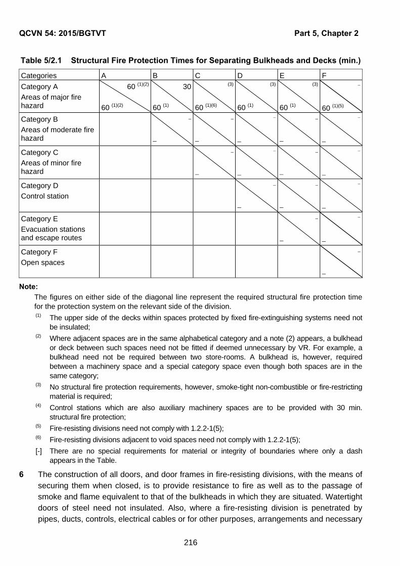
QCVN 54: 2015/BGTVT Part 5, Chapter 2
216
Table 5/2.1 Structural Fire Protection Times for Separating Bulkheads and Decks (min.)
Categories A B C D E F
Category A
Areas of major fire hazard
60 (1)(2)
60 (1)(2)
30
60 (1)
(3)
60 (1)(6)
(3)
60 (1)
(3)
60 (1)
60 (1)(5)
Category B
Areas of moderate fire hazard
_
_
_
Category C
Areas of minor fire hazard
_
_
Category D
Control station
_
_
Category E
Evacuation stations and escape routes
_
Category F
Open spaces
_
Note:
The figures on either side of the diagonal line represent the required structural fire protection time for the protection system on the relevant side of the division. (1) The upper side of the decks within spaces protected by fixed fire-extinguishing systems need not
be insulated; (2) Where adjacent spaces are in the same alphabetical category and a note (2) appears, a bulkhead
or deck between such spaces need not be fitted if deemed unnecessary by VR. For example, a bulkhead need not be required between two store-rooms. A bulkhead is, however, required between a machinery space and a special category space even though both spaces are in the same category;
(3) No structural fire protection requirements, however, smoke-tight non-combustible or fire-restricting material is required;
(4) Control stations which are also auxiliary machinery spaces are to be provided with 30 min. structural fire protection;
(5) Fire-resisting divisions need not comply with 1.2.2-1(5); (6) Fire-resisting divisions adjacent to void spaces need not comply with 1.2.2-1(5);
[-] There are no special requirements for material or integrity of boundaries where only a dash appears in the Table.
6 The construction of all doors, and door frames in fire-resisting divisions, with the means of securing them when closed, is to provide resistance to fire as well as to the passage of smoke and flame equivalent to that of the bulkheads in which they are situated. Watertight doors of steel need not insulated. Also, where a fire-resisting division is penetrated by pipes, ducts, controls, electrical cables or for other purposes, arrangements and necessary

Part 5, Chapter 2 QCVN 54: 2015/BGTVT
217
testing are to be made to ensure that the fire-resisting integrity of the division is not impaired. Where machinery shafts penetrate fire-resisting watertight divisions, arrangements are to be made to ensure that the required watertight and fire-resisting integrity of the division is not impaired.
7 For cargo craft having gross tonnage of 150 and above, the required fire protection time is
to be 30 min. instead of 60 min. as specified in Table 5/2.1. For cargo craft having gross
tonnage of less than 150, fire-resisting divisions need not to comply with requirements in
1.2.2-1(5).
2.4 Restricted Use of Combustible Materials
2.4.1 Application
The requirements in 2.4.2 and 2.4.3 are to apply only to passenger craft, unless otherwise specified elsewhere.
2.4.2 Separating Divisions
1 All separating divisions, ceilings or linings if not a fire-resisting division, are to be of non-combustible or fire-restricting materials.
2 Where insulation is installed in areas in which it could come into contact with any flammable fluids or their vapors, its surface is to be impermeable to such flammable fluids or vapors. The exposed surfaces of vapor barriers and adhesives used in conjunction with insulation materials are to have low flame spread characteristics. The fire insulation in such spaces may be covered by metal sheets (not perforated) or by vapor proof glass cloth sealed at joints.
2.4.3 Furniture and Furnishings
1 Furniture and furnishings in public spaces and crew accommodation are to comply with the following standards :
(1) All case furniture e.g., decks, wardrobes, dressing tables, bureaux and dressers is constructed entirely of approved non-combustible or fire-restricting materials, except that a combustible veneer with a calorific value not exceeding 45 MJ/m2 may be used on the exposed surface of such articles;
(2) All other furniture such as chairs, sofas, tables, is constructed with frames of non-combustible or fire-restricting materials;
(3) All draperies, curtains and other suspended textile materials have qualities of resistance to the propagation of flame in accordance with standards which is considered appropriate by VR;
(4) All upholstered furniture has qualities of resistance to the ignition and propagation of flame in accordance with standards which is considered appropriate by VR;
(5) All bedding components comply with the standards which is considered appropriated by VR; and
QCVN 54: 2015/BGTVT Part 5, Chapter 2
218
(6) All deck finish materials comply with the standards which is considered appropriate by VR.
2.4.4 Surface Materials
1 The following surfaces are to, as a minimum standard be constructed of materials having low flame-spread characteristics. However this requirement does not apply to partitions, windows and side scuttles made of glass which are deemed to be non-combustible:
(1) Exposed surfaces in corridors and stairway enclosures, and of bulkheads, wall and ceiling linings in all accommodation and service spaces and control stations;
(2) Concealed or inaccessible spaces in accommodation, service spaces and control stations.
2 Any thermal and acoustic insulation material, if not in compliance with the requirements for fire-resisting divisions or fire-restricting materials, are to be of non-combustible material.
3 Materials used in the craft, when exposed to fire, are not to emit smoke or toxic gases in quantities that could be dangerous to humans as determined in tests of a standard which is considered appropriate by VR.
4 Void compartments, where low density combustible materials are used to provide buoyancy, are to be protected from adjacent fire hazard areas by fire-resisting divisions, in accordance with Table 5/2.1. Also, the space and closures to it is to be gastight but it is to be ventilated to atmosphere.
5 In compartments where smoking is allowed, suitable non-combustible ash containers are to be provided. In compartments where smoking is not allowed, adequate notices are to be displayed.

Part 5, Chapter 3 QCVN 54: 2015/BGTVT
219
CHAPTER 3 FIRE DETECTION AND EXTINCTION
3.1 Fire Detection Systems
3.1.1 Fixed Fire Detection and Fire Alarm Systems
1 Areas of major fire hazard are to be provided with an approved automatic smoke detection system and manually operated call points to indicate at the control station the location of outbreak of a fire in all normal operating conditions of the installations.
2 In case where deemed necessary by VR, main propulsion machinery rooms are to in addition have detectors sensing other than smoke and be supervised by TV cameras monitored from the operating compartment.
3 Manually operated call points are to be installed throughout the accommodation spaces, service spaces and, where necessary, control stations. One manually operated call point is to be located at each exit from these spaces and from areas of major fire hazard. Control stations not normally occupied (e.g., emergency generator rooms) need not be provided with manually operated call points.
4 Fixed fire detection and fire alarm systems with manually operated call points are to comply with the installation requirements and the design requirements specified in Chapter 7 Part 5 Section II QCVN 21: 2015/BGTVT in addition to the requirements specified in this Chapter.
3.1.2 Fixed Fire Detection and Fire Alarm Systems for Unattended Machinery Spaces
1 A fixed fire detection and fire alarm systems for periodically unattended machinery spaces are to comply with the following requirements in addition to the requirements in 3.1.1-4 above.
(1) The fire detection system is to be so designed and the detectors so positioned as to
detect rapidly the onset of fire in any part of those spaces and under any normal
conditions of operation of the machinery and variations of ventilation as required by
the possible range of ambient temperatures. Except in spaces of restricted height and
where their use is specially appropriate, detection systems using only thermal
detectors are not to be permitted. The detection system is to initiate audible and visual
alarms distinct in both respects from the alarms of any other system not indicating fire,
in sufficient places to ensure that the alarms are heard and observed on the
navigating bridge and by a responsible engineer officer. When the operating
compartment is unmanned the alarm is to sound in a place where a responsible
member of the crew is on duty;
(2) After installation, the system is to be tested under varying conditions of engine
operation and ventilation.
3.2 Fixed Fire-extinguishing Systems
QCVN 54: 2015/BGTVT Part 5, Chapter 3
220
3.2.1 Fixed Fire-extinguishing Systems in Areas of Major Fire Hazard
1 Main propulsion machinery rooms, special category spaces and open vehicle spaces are to be protected by an approved fixed extinguishing system operable from the control position which is adequate for the fire hazard that may exist. The system is to be capable of local manual control and remote control from the continuously manned control stations.
2 For crafts having length of less than 24 m or crafts having small machinery space deemed appropriate by VR, in lieu of fixed extinguishing system specified in -1 above, portable fire extinguishers of suitable capacity and type complying with requirements in 3.4 may be used to extinguish fire in the machinery space through a discharge port on the space's boundaries. Arrangement and calculation for this fire fighting equipment is to be submitted for approval.
3.2.2 Fixed Gas Fire-extinguishing Systems
1 In case where the fire-extinguishing medium for the fixed gas fire-extingushing systems is stored outside a protected spaces, it is to be stored in a room which is to be situated in a safe and readily accessible position and is to be effectively ventilated to the satisfaction of VR. Any entrance to such a storage room is preferably to be direct from the open deck and in any case is to be independent of the protected space. Access doors are to open outwards, and bulkheads and decks which form the boundaries between such rooms and adjoining enclosed spaces are to be gastight, including doors and other closing means of any opening therein. The boundaries of this storage room are to have fire integrity required for a control station in application of Table 5/2.1.
2 Fixed gas fire-extinguishing systems are to comply with the requirements in Chapter 25 Part 5 Section II QCVN 21: 2015/BGTVT.
3 The use of a fire-extinguishing medium which, either by itself or under expected conditions of use will adversely affect the earth's ozone layer and/or gives off toxic gases in such quantities as to endanger persons is not to be permitted.
3.2.3 Fixed Pressure Water-spraying Fire-extinguishing Systems
1 Fixed pressure water-spraying fire-extinguishing systems in machinery spaces are to be comply with Chapter 27 Part 5 Section II QCVN 21: 2015/BGTVT.
2 Fixed pressure water-spraying fire-extinguishing systems in special category spaces and open vehicle spaces are to be comply with the requirements otherwise specified.
3.3 Fire Pumps
3.3.1 General
A craft is to be provided with fire pumps and appropriate associated equipment according to the following 3.3.2 to 3.3.5 or alternative effective fire-extinguishing systems.
3.3.2 Fire Pumps
1 Fire pumps are to be provided in accordance with Table 5/3.1. Each pump is to have at least two thirds the capacity of a bilge pump as determined by 8.4 in Part 3 but not less

Part 5, Chapter 3 QCVN 54: 2015/BGTVT
221
than 25 m3/h. Each fire pump is to be able to deliver sufficient quantity and pressure of water to simultaneously operate the hydrants as required by 3.3.4.
2 For craft which are required to be provided with two fire pumps and more, the arrangement of the pumps is to be such that in the event of a fire in any one compartment all fire pumps will not be put out of action.
3.3.3 Isolation Valves
Isolating valves to separate the section of the fire main within the machinery space containing the main fire pump or pumps from the rest of the fire main are to be fitted in an easily accessible and tenable position outside the machinery spaces. The fire main is to be so arranged that when the isolating valves are shut all the hydrants on the craft, except those in the machinery space referred to above, can be supplied with water by a fire pump not located in this machinery space through pipes which do not enter this space. The fire main is to be capable of being drained and is to be fitted with valves arranged so that fire main branches can be isolated when the main is used for purposes other than fire-fighting.
Table 5/3.1 Required Number of Fire Pumps
GT < 150 150 GT < 300 300 GT < 1000 1000 GT
Passenger craft 4 buckets One independently driven pump Two independently driven pump
Cargo craft Not required One independently driven pump
3.3.4 Hydrants
Hydrants are to be arranged so that any location on the craft can be reached by the water jets from two fire hoses from two different hydrants, one of the jets being from a single length of hose. In special category spaces and open vehicle spaces, hydrants are be located so that any location within the space can be reached by two water jets from two different hydrants, each jet being supplied from a single length of hose. One hydrant is to be located in the vicinity of and outside each entrance to a machinery space.
3.3.5 Fire Hoses and Nozzles
1 Each fire hose is to be of non-perishable material and have a length of at least 10 m, not more than 15 m in machinery spaces and not more than 20 m for other spaces and open decks. Fire hoses, together with any necessary fittings and tools, are to be kept ready for use in conspicuous positions near the hydrants.
2 In machinery spaces and boiler rooms, a set of a fire hose and a nozzle is to be provided with for each hydrant.
3 Each fire hose is to be provided with a nozzle of an approved dual purpose type (i.e. spray/jet type) incorporating a shutoff.
3.4 Portable Fire Extinguishers

QCVN 54: 2015/BGTVT Part 5, Chapter 3
222
3.4.1 Portable Fire Extinguishers in Control Stations, Accommodation and Service Spaces
1 Control stations, accommodation spaces and service spaces are to be provided with portable fire extinguishers of appropriate types in accordance with Table 5/3.2.
2 In addition to -1 above, at least one extinguisher suitable for machinery space fires is to be positioned outside each machinery space entrance.
3 Portable Fire Extinguishers are to comply with the requirements in Chapter 24 Part 5 Section II QCVN 21: 2015/BGTVT.
Table 5/3.2 Required Number of Portable Fire Extinguishers
Number and Type
Number
Type of portable fire extinguishers
Passenger Craft Cargo Craft
Applicable spaces
GT < 1000 GT 1000 GT < 1000 GT 1000
Navigation bridge and fire control station
Portable extinguishers are to be located so that no point is spaced more than approximately 15 m walking distance from an extinguisher.
At least two on each deck and at least four in total.
One foam type and another one CO2 or dry type, for each space.
For crafts having GT = 2,000 and above, one foam type and two CO2 or dry type, for each space.
At least four in total.
One Foam, CO2 or Dry
Corridors
One for each 30 m of the corridor length or part thereof
One for each 50m of the corridor length or part thereof
Foam, CO2 or Dry
Public spaces
One for each 20m of the corridor length or part thereof
_ Foam or Dry
Galley One One Foam or CO2
Shopping booths and carpenter's shops
One One Foam or Dry
Paint lockers
One (outside of each entrances) Foam, CO2 or Dry
Notes _ At least five in total
_ At least five in
total _
3.5 Fire Control Plan
3.5.1 Fire Control Plan

Part 5, Chapter 3 QCVN 54: 2015/BGTVT
223
1 There are to be permanently exhibited, for the guidance of the master and officers of the craft, fire control plans showing clearly for each deck the following positions:
(1) Control stations;
(2) Sections of the craft which are enclosed by fire-resisting divisions together with particulars of the fire detection and alarms systems, the sprinkler installations, the fixed and portable fire-extinguishing appliances;
(3) Means of access to different compartments and decks in the craft;
(4) Ventilating system including particulars of the fan control positions, the position of dampers and identification numbers of the ventilating fans serving each section of the craft;
(5) Positions of all means of control referred to in 3.1, 3.2, 3.3 and 4.1.1-3 of this Part.
2 A duplicate set of fire control plans or a booklet containing such plans is to be permanently stored in a prominently marked weathertight enclosure outside the deckhouse for the assistance of shoreside fire-fighting personnel.
3 For crafts having length less than 24 m, not engaged in international voyages, the requirements in -2 may be waived.
3.6 Fireman's Outfits
3.6.1 Fireman's Outfits
1 Passenger crafts are to carry at least one fireman's outfit complying with the requirements of 3.6.3. However, for passenger crafts having GT of less than 300, this requirement may be waived.
2 Craft having special category spaces and open vehicle spaces are to carry at least two fireman's outfits complying with the requirements of 3.6.3.
3 The Society may require additional sets of personal equipment and breathing apparatus, due regard to the size and type of the craft.
3.6.2 Storage of Fireman's Outfits
The fireman's outfits or sets of personal equipment are to be so stored as to be easily accessible and ready for use and, where more than one fireman's outfit or more than one set of personal equipment is carried, they are to be stored in widely separated positions.
3.6.3 Fireman's Outfit
1 A fireman's outfit is to consist of::
(1) Personal equipment comprising:
(a) Protective clothing of material to protect the skin from the heat radiating from the fire and from burns and scalding by steam or gases. The outer surface is to be water-resistant;
(b) Boots of rubber or other electrically non-conductive material;
(c) A rigid helmet providing effective protection against impact;
QCVN 54: 2015/BGTVT Part 5, Chapter 3
224
(d) An electric safety lamp (hand lantern) of an approved explosion-proof type with a minimum burning period of 3 hours; and
(e) An axe to the satisfaction of VR having a handle provided with high-voltage insulation.
(2) A self-contained compressed-air-operated breathing apparatus of an approved type, the volume of air contained in the cylinders of which are to be at least 1,200 l, or other self-contained breathing apparatus of an approved type which are to be capable of functioning for at least 30 minutes. Two spare charges suitable for use with the apparatus are to be provided for each required apparatus.
(3) For each breathing apparatus, a fireproof lifeline of approximately 30 m in length and strength is to be provided capable of being attached by means of a snaphook to the harness of the apparatus or to a separate belt in order to prevent the breathing apparatus becoming detached when the lifeline is operated. The lifeline is to be subjected to a test by static load of 3.5 kN for 5 minutes.

Part 5, Chapter 4 QCVN 54: 2015/BGTVT
225
CHAPTER 4 ADDITIONAL REQUIREMENTS FOR MACHINERY SPACES
4.1 Additional Requirements for Machinery Spaces
4.1.1 Fuel and Other Flammable Fluid Tanks and Systems
1 Tanks containing fuel and other flammable fluids are to be separated from passenger, crew, and baggage compartments by vapor-proof enclosures or cofferdams which are suitably ventilated and drained.
2 Fuel oil tanks are not to be located in or contiguous to major fire hazard areas. However, flammable fluids of a flashpoint not less than 60 °C may be located within such areas provided the tanks are made of steel or other equivalent material. The use of aluminum in lubricating oil sump tanks for engines, or in lubricating oil filter housings fitted integral with the engines, is accepted.
3 Every oil fuel pipe which, if damaged, would allow oil to escape from a storage, settling or daily service tank is to be fitted with a cock or valve directly on the tank capable of being closed from a position outside the space concerned in the event of a fire occurring in the space in which such tanks are situated. However, this requirement need not to be complied with for fuel tanks having capacity of less than 0.5 m3.
4 Pipes, valves and couplings conveying flammable fluids are to be of steel or such alternative material satisfactory to VR, in respect of strength and fire integrity having regard to the service pressure and the spaces in which they are installed. Wherever practicable, the use of flexible hoses is to be avoided.
5 Pipes, valves and couplings conveying flammable fluids are to be arranged as far from hot surfaces or air intakes of engine installations, electrical appliances and other potential sources of ignition as is practicable and be located or shielded so that the likelihood of fluid leakage coming into contact with such sources of ignition is kept to a minimum.
4.1.2 Exhaust Gas Pipes
1 The exhaust gas pipes are to be arranged so that the risk of fire is kept to a minimum. To this effect, the exhaust system is to be insulated and all the compartments and structures which are contiguous with the exhaust system, or those which may be affected by increased temperatures caused by waste gases in normal operation or in an emergency, are to be constructed of non-combustible material or be shielded and insulated with non-combustible material to protect from high temperatures.
2 The design and arrangement of the exhaust manifolds or pipes are to be such as to ensure the safe discharge of exhaust gases.
4.1.3 Miscellaneous Requirements
1 Craft are to comply with the following miscellaneous requirements on fire safety measures for machinery spaces:
(1) Means are to be provided in machinery spaces to ensure prevention of accumulation of flammable vapors under normal service condition by positive means of ventilation capable of releasing smoke in the event of a fire;

QCVN 54: 2015/BGTVT Part 5, Chapter 4
226
(2) The number of skylights, doors, ventilators, openings in funnels to permit exhaust ventilation and other openings to machinery spaces is to be reduced to a minimum consistent with the needs of ventilation;
(3) The openings given in (2) above are to be provided with closing appliances which are made of steel or other equivalent material and are operable from outside the machinery spaces, where they will not be cut off in the event of a fire in the spaces they serve. The controls are to be easily acceptable as well as prominently and permanently marked and are to indicate whether the shut-off is open or closed;
(4) The doors fitted in boundary bulkheads of main propulsion machinery rooms are to be of self-closing type to prevent the spread of fire to other spaces;
(5) In addition to the requirements given in (1) to (4) above, periodically unattended machinery spaces are to be provided with fire protection arrangements as considered appropriate by VR having due regard to the risk of a fire where deemed necessary by VR.

Part 5, Chapter 5 QCVN 54: 2015/BGTVT
227
CHAPTER 5 PROTECTION OF SPECIAL CATEGORY SPACES
5.1 Protection of Special Category Spaces
5.1.1 Structural Protection
1 Boundaries of special category spaces are to be insulated in accordance with Table 5/2.1.
2 The vehicle deck of a special category space or a ro-ro space, including an open ro-ro space, need only be insulated on the underside if required. Vehicle decks located totally within ro-ro spaces may be accepted without structural fire protection, provided these decks are not part of, or do not provide support to, the crafts main load-carrying structure and provided satisfactory measures are taken to ensure that the safety of the craft, including fire-fighting abilities, integrity of fire resisting divisions and means of evacuation, is not affected by a partial or total collapse of these internal decks.
3 Indicators are to be provided on the navigating bridge which are to indicate when any door leading to or from the special category space is closed.
5.1.2 Patrols and Fire Detection
1 A continuous fire patrol is to be maintained in special category spaces unless a fixed fire detection and fire alarm system, complying with the requirements of 3.1.1 of this Part and a television surveillance system are provided. The fixed fire detection system is to be capable of rapidly detecting the onset of fire. The spacing and location of detectors are to be tested taking into account the effects of ventilation and other relevant factors.
2 Manually operated call points are to be provided as necessary throughout the special category spaces and one is to be placed close to each exit from such spaces.
5.1.3 Fixed Fire-extinguishing System
1 Each special category space is to be fitted with an approved fixed pressure water-spraying system for manual operation which is to protect all parts of any deck and vehicle platform in such space, provided that VR may permit the use of any other fixed fire-extinguishing system that has been shown by full-scale test in conditions simulating a flowing petrol fire in a special category space to be not less effective in controlling fires likely to occur in such a space.
2 Fixed fire-extinguishing systems are to fulfill the following requirement:
(1) The valve manifold shall be provided with a pressure gauge, and each of the valves shall be marked to identify the protected areas;
(2) Instructions for maintenance and operation of the installation shall be set up in the room where the valves are located;
(3) The piping system shall be provided with a sufficient number of drainage valves.
5.1.4 Portable Fire Extinguishers

QCVN 54: 2015/BGTVT Part 5, Chapter 5
228
Portable fire extinguishers are to be located so that no point in the space is more than approximately 20 m walking distance from an extinguisher, provided that at least one portable extinguisher is located at each access to such a space. "No Smoking" notations are to posted in way of all access to these spaces.
5.1.5 Ventilation System
1 There is to be provided an effective power ventilation system for the special category spaces sufficient to give at least 10 air changes per hour while navigating and 20 air changes per hour at the quayside during vehicle loading and unloading operations. The system for such spaces is to be entirely separated from other ventilation systems and are to be operating at all times when vehicles are in such spaces. Ventilation ducts serving special category spaces capable of being effectively sealed are to be separated for each such space. The system is to be capable of being controlled from a position outside such spaces.
2 The ventilation is to be such as to prevent air stratification and the formation of air pockets.
3 Means are to be provided to indicate in the operating compartment any loss or reduction of the required ventilating capacity.
4 Arrangements are to be provided to permit a rapid shutdown and effective closure of the ventilation systems in case of fire, taking into account the weather and sea conditions.
5 Ventilation ducts, including dampers are to be made of steel or other equivalent material.
5.1.6 Scuppers, Bilge Pumping and Drainage
1 In view of the serious loss of stability which could arise due to large quantities of water accumulating on the deck or decks consequent to the operation of the fixed pressure water-spraying system, pumping and drainage arrangements are to be such as to prevent such accumulation. Scuppers fitted for this purpose are to be so arranged as to ensure that such water is rapidly discharged directly overboard. Alternatively, pumping and drainage facilities are to be provided in additional to the requirements of Chapter 8 in Part 9. When it is required to maintain watertight or weathertight integrity, as appropriate, the scuppers is to be arranged so that they can be operated from outside the space protected.
2 Scuppers and drainage pumps fitted in accordance with -1 above are to comply with following requirements:
(1) The amount of water for which drainage is to be provided is to take into account the capacity of both the water spraying system pumps and the required number of fire hose nozzles;
(2) The drainage system is to have a capacity of not less than 125% of the capacity specified in (1) above;
(3) Bilge wells are to be of sufficient holding capacity and are to be arranged at the side shell of the ship at a distance from each other of not more than 40 m in each watertight compartments.
5.1.7 Precautions against Ignition of Flammable Vapors
Part 5, Chapter 5 QCVN 54: 2015/BGTVT
229
1 On any deck or platform, if fitted, on which vehicles are carried and on which explosive vapors might be expected to accumulate, except platforms with openings of sufficient size permitting penetration of petrol gases downwards, equipment which may constitute a source of ignition of flammable vapors and, in particular, electrical equipment and wiring, are to be installed at least 450 mm above the deck or platform. Electrical equipment installed at more than 450 mm above the deck or platform are to be of a type approved so enclosed and protected as to prevent the escape of sparks. However, if the installation of electrical equipment and wiring at less than 450 mm above the deck or platform is necessary for the safe operation of the craft, such electrical equipment and wiring may be installed provided that it is of a type approved for use.
2 If installed in an exhaust ventilation duct, electrical equipment are to be of a type approved for use. The requirement and wiring, if fitted, are to be of a type approved for use and the outlet from any exhaust duct is to be sited in a safe position, having regard to other possible sources of ignition.
5.2 Protection of Cargo Spaces and Open Vehicle Spaces
5.2.1 General
Cargo spaces and open vehicle spaces, except open deck areas or refrigerated holds, are to be in accordance with the provisions specified in following 5.2.2 through 5.2.5.
5.2.2 Structural Protection
1 Boundaries of cargo spaces and open vehicle space are to be insulated in accordance with Table 5/2.1. The standing deck of the open vehicle space need only be insulated on the underside if required.
2 Indicators are to be provided on the navigation bridge which are to indicate when any door leading to or from the open vehicle space is closed.
5.2.3. Patrol and Fire Detection
1 A continuous fire patrol is to be maintained in cargo spaces and open vehicle spaces unless a fixed fire detection and fire alarm system, complying with the requirements of 3.1.1 of this Part and a television surveillance system are provided. The fixed fire detection system is to be capable of rapidly detecting the onset of fire. The spacing and location of detectors are to be tested taking into account the effects of ventilation and other relevant factors.
2 Manually operated call points are to be provided as necessary throughout the special category spaces and one is to be placed close to each exit from such spaces.
5.2.4 Fixed Fire-extinguishing Systems
Each cargo space is to be protected by fixed fire extinguishing systems specified in 3.2 of this Part. Each open vehicle space, however, is to be protected by the fixed pressure water-spraying system specified in 3.2.3-2 of this Parts.
5.2.5 Portable Fire Extinguishers

QCVN 54: 2015/BGTVT Part 5, Chapter 5
230
Portable fire extinguishers are to be located so that no point in the space is more than approximately 20 m walking distance from an extinguisher, provided that at least one portable extinguisher is located at each access to such a space. "No Smoking" notations are to posted in way of all access to those spaces.
Part 5, Chapter 6 QCVN 54: 2015/BGTVT
231
CHAPTER 6 MEANS OF ESCAPE
6.1 Exits and Means of Escape
6.1.1 General
1 Easy, safe and quick accesses from the operating compartment to the passenger accommodation are to be provided. In order to ensure immediate assistance from the crew in an emergency situation, the crew accommodation, including any cabins, is to be located with due regard to easy, safe and quick access to the public spaces from inside the craft.
2 The design of the craft is to be such that all occupants may safely evacuate the craft to the open deck and then into survival craft under all emergency conditions, by day or by night. The positions of all exits which may be used in an emergency, and of all life-saving appliances, the practicability of the evacuation procedure are to be suitable for this purpose.
3 Public spaces, evacuation routes, exits, lifejacket stowage, survival craft stowage, and the embarkation stations are to be clearly and permanently marked and illuminated.
4 Each enclosed public space and similar permanently enclosed space allocated to passengers or crew is to be provided with at least two exits arranged in the opposite ends of the space. Exits are to be safely accessible and are to provide a route to a normal point of boarding or disembarking from the craft.
5 Exit doors are to be capable of being readily operated from inside and outside the craft in daylight and in darkness. The means of operation are to be obvious, rapid and of adequate strength.
6 The closing, latching and locking arrangements for exits are to be such that it is readily apparent to the appropriate crew member when the doors are closed and in a safe operational condition, either in direct view or by an indicator. The design of external doors is to be such as to eliminate the possibility of jamming by ice of debris.
7 The craft is to have a sufficient number of exits which are suitable to facilitate the quick and unimpeded escape of persons wearing approved lifejackets in emergency conditions, such as collision damage or fire.
8 Sufficient space for a crew member is to be provided adjacent to exits for ensuring the rapid evacuation of passengers.
9 All exits, together with their means of opening, are to be adequately marked for the guidance of passengers. Clear markings, including the location of the fire control, is to be provided for the guidance of rescue personnel outside the craft.
10 Footholds, ladders, etc., provided to give access from the inside to exits, are to be of rigid construction and permanently fixed in position. Permanent handholds are to be provided whenever necessary to assist persons using exits, and are to be suitable for conditions when the craft has developed any possible angles of list or trim.

QCVN 54: 2015/BGTVT Part 5, Chapter 6
232
11 At least two unobstructed evacuation paths are to be available for the use of each person. Evacuation paths are to be disposed such that adequate evacuation facilities will be available in the event of any likely damage or emergency conditions, and evacuation paths are to have adequate lighting supplied from the main and emergency sources of power. Doors providing escape from a space are to be situated at opposite ends of the space. Where the doors providing escape from a space are situated in the same end of the space, the distance between those doors is to be greater than the maximum length of the space.
12 The dimensions of passages, doorways and stairways which form part of evacuation paths are to be such as to allow easy movement of persons when wearing lifejackets. There are to be no protrusions in evacuation paths which could cause injury, ensnare clothing, damage lifejackets or restrict evacuation of disabled persons. Requirements of this paragraph do not apply to aisles (fore-aft passageways separating seating areas) or to spaces between adjacent rows of seats.
13 Adequate notices are to be provided to direct passengers to exits.
14 Provision are to be made on board for embarkation stations to be properly equipped for evacuation of passengers into life-saving appliances. Such provision are to include handholds, anti-skid treatment of the embarkation deck, and adequate space which is clear of cleats, bollards and similar fittings.
6.1.2 Means of Escape from Machinery Spaces
1 At least two means of escape from the machinery spaces are to be provided, and they are to be arranged as widely separated as possible. At least one means of escape from a machinery space shall consist of either a ladder leading to a door or hatch (not being a horizontal flush-hatch) or a door located in the lower part of that space and giving access to an adjacent compartment from which a safe means of escape is provided. However, VR may dispense with one set of means of escape paying due regard to dimensions and arrangement of the machinery spaces.
2 Stairways, ladders, etc. which are part of means of escape from machinery spaces are to be of ample strength and to be effectively secured to the hull constructions. Raw materials which are easily dehardening or melting such as plastics are not to be used for these equipment.
3 Notwithstanding the above, spaces that are only entered occasionally by crew members may have only one means of escape provided that it is independent of watertight doors.
6.1.3 Means of Escape from Special Category Spaces and Open Vehicle Spaces
1 Means of escape are to be provided at least in the fore, midship and aft part of respective special category spaces and the open vehicle spaces. These means of escape are to be placed in both wings of respective spaces unless these means of escape are placed at centre line of such spaces.
2 Means of escape are to be so located that no point in the space is more than 40 m walking distance from the means of escape. Where the arrangement of means of escape required

Part 5, Chapter 6 QCVN 54: 2015/BGTVT
233
by -1 above cannot comply with this requirement, additional means of escape are to be appropriately so arranged to comply with this requirement.
3 Stairways, ladders, etc., which are part of means of escape from the special category spaces and open vehicle spaces are to be of ample strength and to be effectively secured to the hull constructions. Raw materials which are easily dehardening or melting such as plastics are not to be used for these equipment.
4 Where stores and lockers have only exits facing to special category spaces or open vehicle spaces, VR may require to provide additional means of escape which directly escape to the outside of the special category spaces or open vehicle spaces paying due regard to dimensions and use of such spaces.
5 Special category spaces used for stowage of motor vehicles are to be provided with walkways having a width of at least 600 mm leading to a safe means of escape.

Part 6, Chapter 1 QCVN 54: 2015/BGTVT
235
PART 6 BUOYANCY, STABILITY AND SUBDIVISION
CHAPTER 1 GENERAL
1.1 General
1.1.1 General Requirements
1 A craft is to be provided with:
(1) Stability characteristics and stabilization systems adequate for safety when the craft is operated in the non-displacement mode and during the transient mode;
(2) Buoyancy and stability characteristics adequate for safety where the craft is operated in the displacement mode, both in the intact condition and the damaged condition; and
(3) Stability characteristics in the non-displacement and transient modes adequate to transfer the craft safely to displacement mode in case of any system malfunction.
1.1.2 Definitions
1 For the purpose of this and other chapters, unless expressly defined otherwise, the following definitions apply:
(1) "Down flooding point" means any opening, irrespective of size, that would permit passage of water through a water/weathertight structure (e.g., opening windows), however excludes any opening kept closed to an appropriate standard of water/weathertightness at all times other than when required for access or for operation of portable submersible bilge pumps in an emergency (e.g., non-opening windows of similar strength and weathertight integrity to the structure in which they are installed);
(2) "Fully submerged foil" means a foil having no lift components piercing the surface of the water in the foil borne mode;
(3) "Multihull craft" means a craft which in any normally achievable operating trim or heel angle, has a rigid hull structure which penetrates the surface of the sea over more than one discrete area;
(4) "Permeability" of a space means the percentage of the volume of that space which can be occupied by water;
(5) "Skirt" means a downwardly-extending, flexible structure used to contain or divide an air cushion;
(6) "Watertight" in relation to a structure means capable of preventing the passage of water through the structure in any direction under the head of water likely to occur in the intact or damaged condition;
(7) "Weathertight" means that water will not penetrate into the craft in any wind and wave conditions up to those specified as critical design conditions.
1.1.3 Ice Accretion Allowances

QCVN 54: 2015/BGTVT Part 6, Chapter 1
236
Account are to be taken of the effect of icing in the stability calculations. Ice accretion allowances are to be in accordance with requirements in 2.4 Part 10 Section II QCVN 21: 2015/BGTVT.
1.1.4 Equivalent method
1 Other means of demonstrating compliance with the requirements of this Part may be accepted, provided that the method chosen can be shown to provide an equivalent level of safety. Such methods may include:
(1) Mathematical simulation of dynamic behavior;
(2) Scale model testing;
(3) Full-scale trials.
1.2 Buoyant spaces
1.2.1 Reserve of Buoyancy
1 All craft are to have a sufficient reserve of buoyancy at the design waterline to meet the intact and damage stability requirements of this Part. The Society may require a larger reserve of buoyancy to permit the craft to operate in any of its intended modes. This reserve of buoyancy is to be calculated by including only those compartments which are:
(1) Watertight;
(2) Accepted as having scantlings and arrangements adequate to maintain their watertight integrity; and
(3) Situated in locations below a datum, which may be a watertight deck or equivalent structure of a non-watertight deck covered by a weathertight structure as defined in 1.2.4.
2 Where a buoyant space may be subjected to increased fluid pressure in the equilibrium position after damage, the boundaries and associated openings and penetrations of that space are to be of sufficient strength and watertight for that pressure.
1.2.2 Checking of Watertight Integrity
Arrangements are to be provided for checking the watertight integrity of those compartments taken into account in 1.2.1.
1.2.3 Requirements for Structures above the Datum
1 Where entry of water into structures above the datum as defined in 1.2.1(3) would significantly influence the stability and buoyancy of the craft, such structures are to be:
(1) Of adequate strength to maintain the weathertight integrity and fitted with weathertight closing appliances; or
(2) Provided with adequate drainage arrangements; or
(3) An equivalent combination of both measures.

Part 6, Chapter 1 QCVN 54: 2015/BGTVT
237
1.2.4 Maintenance of Weathertight Integrity
The means of closing openings in the boundaries of weathertight structures are to be such as to maintain weathertight integrity in all operational conditions.
1.3 Intact Stability in the Displacement Mode
1.3.1 Intact Stability for Hydrofoil Craft
Hydrofoil craft fitted with surface-piercing foils and/or fully submerged foils are to have
sufficient stability under all permitted cases of loading to comply with the relevant
provisions in Appendix A - "Methods relating to the intact stability investigation of hydrofoil
craft". In this case, when subjected to the greater of the heeling moments in 1.1.1-2 and -4
of Appendix A, a heel angle of less than 10° is to be maintained.
1.3.2 Intact Stability for Multihull Craft
Multihull craft are to have sufficient stability under all permitted cases of loading to comply with the relevant provisions in Appendix B - "Stability of multihull craft".
1.3.3 Intact Stability for Any Other Craft
1 Any other craft are to meet the following criteria in all permitted conditions of loading :
(1) Weather criterion in 2.1 Part 10 Section II QCVN 21: 2015/BGTVT for crafts of unrestricted, restricted I, II and III area of navigation. Wind presure (Pi) is to be taken as follows:
- 500 Pa for unrestricted;
- 360 Pa for restricted I;
- 220 Pa for restricted II and III.
(2) The area under the righting lever curve (GZ-curve) is not to be less than 0.07 m-rad
up to = 15° when the maximum righting lever (GZMAX) occurs at = 15° and 0.055
m-rad up to = 30° when GZMAX occurs at = 30° or above.
Where GZMAX occurs at angles of between = 15° and = 30°, the corresponding area under the righting lever curve is not to be less than that obtained from the following formula:
A = 0.055 + 0.001(30° -max) (m-rad)
Where: max is the angle of heel in degrees at which the righting lever curve reaches
its maximum;
(3) The area under the righting lever curve between = 30° and = 40° or between =
30° and the angle of flooding f, if this angle is less than 40°, is not to be less than 0.03 m-rad;
(4) The righting lever (GZ) is to be at least 0.20 m at an angle of heel equal to or greater

QCVN 54: 2015/BGTVT Part 6, Chapter 1
238
than 30°;
(5) GZMAX is to occur at an angle of heel not less than 15°; and
(6) The initial metacentric height (G0M) is not to be less than 0.15 m.
1.3.4 Equivalent Criteria
Where the characteristics of the craft are unsuitable for application of 1.3.3, VR may accept alternative criteria equivalent to those stipulated in 1.3.3, appropriate to the type of craft and area of operation.
1.4 Intact Stability of Craft in the Non-Displacement Mode
1.4.1 Application
The requirements of this section and section 2.2.2 of this Part are to be applied on the assumption that any stabilization systems fitted are fully operational.
1.4.2 Calculation on Stability
Suitable calculations are to be carried out and/or tests conducted to demonstrate that, when operating in the non-displacement and transient modes within approved operational limitations, the craft will, after a disturbance causing roll, pitch, heave or heel due to turning or any combination thereof, return to the original attitude.
1.4.3 Stability of Sister Craft
The roll and pitch stability on the sister craft may be qualitatively assessed by the results of suitable calculations or tests for the first and/or any other craft of a series.
1.4.4 Stability of Craft fitted with Surface Piercing Structure or Appendages
Where craft are fitted with surface piercing structure or appendages, precautions are to be taken against dangerous attitudes or inclinations and loss of stability subsequent to a collision with a submerged or floating object.
1.4.5 Stability of Air Cushion Vehicle
In designs where periodic use of cushion deformation is employed as a means of assisting craft control, or periodic use of cushion air exhausting to atmosphere for purposes of craft maneuvreing, the effects upon cushion-borne stability are to be determined, and the limitations on the use by virtue of craft speed or attitude are to be established.
1.4.6 Requirements for Flexible Skirts of an Air Cushion Vehicle
In the case of an air cushion vehicle fitted with flexible skirts, it is to be demonstrated that the skirts remain stable under operational conditions.
1.5 Intact Stability in the Transient Mode
1.5.1 Time of the Transient Mod

Part 6, Chapter 1 QCVN 54: 2015/BGTVT
239
Under weather conditions up to the worst intended conditions, the time to pass from the displacement mode to the non-displacement mode and vice versa are to be minimized unless it is demonstrated that no substantial reduction of stability occurs during this transition.
1.5.2 Hydrofoil Craft
Hydrofoil craft are to have sufficient intact stability in transient mode to comply with the relevant provisions in Appendix A - "Methods relating to the intact stability investigation of hydrofoil craft".
1.6 Buoyancy and Stability in the Displacement Mode following Damage
1.6.1 Application
The requirements of this section apply to all permitted conditions of loading.
1.6.2 Permeability
For the purpose of making damage stability calculations, the volume and surface permeabilities are to be in accordance with Table 6/1.1 in general.
1.6.3 Permeability Determined by Direct Calculation
Notwithstanding 1.6.2, permeability determined by direct calculation are to be used where a more onerous condition results, and may be used where a less onerous condition results from that provided according to 1.6.2.
Table 6/1.1 Permeabilities of Space
Spaces Permeability
Appropriated to cargo or stores
Occupied by accommodation
Occupied by machinery
Intended for liquids
Appropriated for cargo vehicles
Void spaces
60
95
85
0 or 95*
90
95
Note: * Whichever results in the more severe requirements.
1.6.4 Buoyancy of Low Density Foam or Other Media
1 The Society may permit the use of low density foam or other media to provide buoyancy in void spaces, provided that satisfactory evidence is provided that any such proposed medium is the most suitable alternative and is:
(1) Of closed cell form if foam, or otherwise impervious to water absorption;
(2) Structurally stable under service conditions;
(3) Chemically inert in relation to structural materials with which it is in contact or other substances with which the medium is likely to be in contact; and

QCVN 54: 2015/BGTVT Part 6, Chapter 1
240
(4) Properly secured in place and easily removable for inspection of the void spaces.
2 The Administration may permit void bottom spaces to be fitted within the watertight envelope of the hull without the provision of a bilge system or air pipes provided that:
(1) The structure is capable of withstanding the pressure head after any of the damages required by this Part;
(2) When carrying out a damage stability calculation in accordance with the requirements of this Part, any void space adjacent to the damaged zone is to be included in the calculation and the criteria in 1.6, 2.3 and 3.2 complied with;
(3) The means by which water which has leaked into the void space is to be removed are to be included in the craft operating manual;
(4) Adequate ventilation is provided for inspection of the space under consideration.
3 Any damage of a lesser extent than that postulated in 1.6.5-1 to 1.6.5-3(1), as applicable, which would result in a more severe condition shall also be investigated. The damage is to be assumed to have the shape of a parallelepiped.
1.6.5 Damage Assumptions
1 Extent of side damage:
(1) The following side damage is to be assumed anywhere on the periphery of the craft:
(a) The longitudinal extent of damage, in m, is to be 0.751/3 or (3+0.2251/3) or 11 m, whichever is the least;
(b) The transverse extent of penetration into the craft is to be 0.21/3.
However, where the craft is fitted with inflated skirts or with non-buoyant side structures, the transverse extent of penetration is to be at least 0.121/3 into the main buoyancy hull or tank structure;
(c) The vertical extent of damage is to be taken for the full vertical extent of the craft.
Where: volume of displacement corresponding to the design waterline, 3m .
2 Extent of bottom damage:
(1) In areas vulnerable to raking damage:
(a) Application
(i) Any part of the surface of the hull(s) is considered to be vulnerable to raking damage if:
- It is in contact with the water at maximum speed in smooth water; and
- It also lies below two planes which are perpendicular to the craft centreline plane and at heights as shown in Fig. 6/1.1;
- For multihulls, individual hulls are to be considered separately.
(ii) Raking damage is to be assumed to occur along any fore-and-aft line on the surface of the hull(s) between the keel and the upper limit defined in the Fig.
Part 6, Chapter 1 QCVN 54: 2015/BGTVT
241
6/1.1;
(iii) Damage shall not be applied at the same time as that defined in 1.6.5-1 or 1.6.5-2(2).
(b) Extent
(i) Two different longitudinal extents are to be considered separately:
- 55% of the length L, measured from the most forward point of the underwater buoyant volume of each hull; and
- A percentage of the length L, applied anywhere in the length of the craft, equal to 35% for craft where L = 50 m and over and equal to (L/2 + 10)% for craft where L is less than 50 m.
(ii) Except as provided below, the penetration normal to the shell is to be 0.041/3 or 0.5 m, whichever is the lesser, in association with a girth along the shell equal to 0.11/3. However, this penetration or girth shall under no circumstances extend above the vertical extent of the vulnerable area as specified in 1.6.5-2(1)a).
(2) In areas not vulnerable to raking damage
(a) Application
This applies to all parts of the hull(s) below the design waterline which are not defined as vulnerable to raking damage in 1.6.5-2(1). Damage shall not be applied at the same time as that defined in 1.6.5-1 or 1.6.5-2(1).
(b) Extent
The following extent of damage is to be assumed:
(i) The length of damage in the fore-and-aft direction is to be 0.751/3, or (3 m + 0.2251/3), or 11 m whichever is the least;
(ii) The athwartships girth of damage is to be 0.21/3;
(iii) The depth of penetration normal to the shell is to be 0.021/3.
3 Remarks
(1) In applying 1.6.5-2(1) and (2) to multihull craft, an obstruction at or below the design waterline of up to 7 m width is to be considered in determining the number of hulls damaged at any one time. The requirement of 1.6.4-3 shall also be applied.
(2) Downflooding openings referred to in 1.6.5-3(1) and (2) shall include doors and hatches which are used for damage control or evacuation procedures, but may exclude those which are closed by means of weathertight doors and hatch covers and not used for damage control or evacuation procedures.
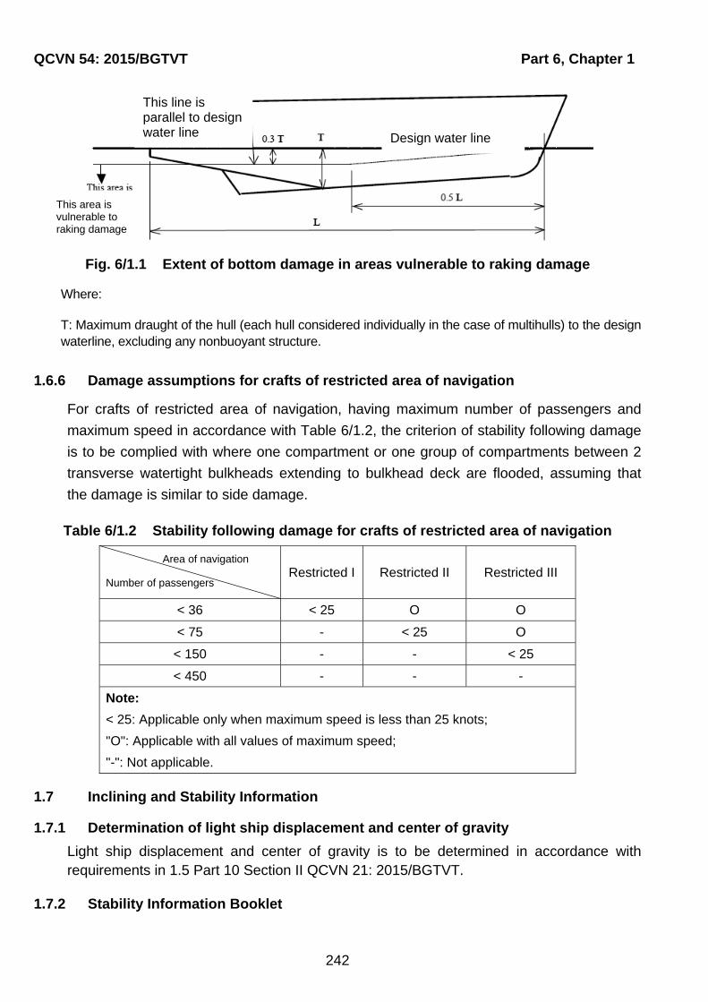
QCVN 54: 2015/BGTVT Part 6, Chapter 1
242
Fig. 6/1.1 Extent of bottom damage in areas vulnerable to raking damage
Where:
T: Maximum draught of the hull (each hull considered individually in the case of multihulls) to the design waterline, excluding any nonbuoyant structure.
1.6.6 Damage assumptions for crafts of restricted area of navigation
For crafts of restricted area of navigation, having maximum number of passengers and
maximum speed in accordance with Table 6/1.2, the criterion of stability following damage
is to be complied with where one compartment or one group of compartments between 2
transverse watertight bulkheads extending to bulkhead deck are flooded, assuming that
the damage is similar to side damage.
Table 6/1.2 Stability following damage for crafts of restricted area of navigation
Area of navigation
Number of passengers Restricted I Restricted II Restricted III
< 36 < 25 O O
< 75 - < 25 O
< 150 - - < 25
< 450 - - -
Note:
< 25: Applicable only when maximum speed is less than 25 knots;
"O": Applicable with all values of maximum speed;
"-": Not applicable.
1.7 Inclining and Stability Information
1.7.1 Determination of light ship displacement and center of gravity
Light ship displacement and center of gravity is to be determined in accordance with requirements in 1.5 Part 10 Section II QCVN 21: 2015/BGTVT.
1.7.2 Stability Information Booklet
This area is vulnerable to raking damage
This line is parallel to design water line Design water line

Part 6, Chapter 1 QCVN 54: 2015/BGTVT
243
A stability information booklet is to be provided on board. The information is to include particulars appropriate to the craft and is to reflect the craft's loading conditions and mode of operation. Any enclosed superstructures or deckhouses include in the cross curves of stability and the critical downflooding points and angles are to be identified.
1.7.3 Submission of Results of Stability Experiments
A report of each inclining or lightweight survey carried out in accordance with this Part and of the lightship condition particulars which are calculated from the test result is to be submitted to VR for approval.
1.7.4 Keeping of Stability Information Booklet
A stability information booklet approved in accordance with preceding 1.7.2 and/or 1.7.3 is to be provided on board.
1.7.5 Draught Marks at Bow and Stern
Every craft is to have scales of draughts marked clearly at the bow and stern. In the case where the draught marks are not located where they are easily readable, or operational constraints for a particular trade make it difficult to read the draught marks, then the craft is to also be fitted with a reliable draught indicating system by which the bow and stern draughts can be determined. For amphibious air-cushion vehicles this may be achieved by the use of draught gauges in conjunction with deck datum plates.
1.7.6 Draught Marks
The draught marks are to be accurately determined and are located on the hull in a permanent manner.
1.8 Loading and Stability Assessment
1.8.1 Loading Computers
In addition to the stability information booklet, VR may accept the use of an electronic loading and stability computer or equivalent means for the purpose to determine the craft's trim and stability.

QCVN 54: 2015/BGTVT Part 6, Chapter 2
244
CHAPTER 2 REQUIREMENTS FOR PASSENGER CRAFT
2.1 General
2.1.1 Consideration of the Effects of Passenger Weight
1 Where compliance with this Part requires consideration of the effects of passenger weight, the following information are to be used:
(1) The distribution of passengers is 4 persons per square metre;
(2) Each passenger has a mass of 75 kg;
(3) Vertical centre of gravity of seated passengers is 0.3 m above seat;
(4) Vertical centre of gravity of standing passengers is 1.0 m above deck;
(5) Passengers and luggage are to be considered to be in the space normally at their disposal;
(6) Passengers are to be distributed on available deck areas towards one side of the craft on the decks where muster stations are located and in such a way that they produce the most adverse heeling moment;
(7) Passengers assumed to be occupying seats are to be taken as having a vertical centre of gravity corresponding to being seated, with all others standing;
(8) On the decks where assembly stations are located, the number of passengers on each deck is to be that which generates the maximum heeling moment. Any remaining passengers are to be assumed to occupy decks adjacent to those on which the assembly stations are located, and positioned such that the combination of number on each deck and total heeling moment generate the maximum static heel angle;
(9) Passengers may not to be assumed to gain access to the weather deck nor be assumed to crowd abnormally towards either end of the craft unless this is a necessary part of the planned evacuation procedure;
(10) Where there are seats in areas occupied by passengers, one passenger per seat are to be assumed, passengers being assigned to the remaining free areas of the deck (including stairways, if appropriate) at the rate of four per square metre.
2.2 Intact Stability
2.2.1 Intact Stability in the Displacement Mode
The craft are to have sufficient intact stability that, when in still water conditions, the inclination of the craft from the horizontal would not exceed 10° under all permitted cases of loading and uncontrolled passenger movements as may occur.
2.2.2 Intact Stability in the Non-Displacement Mode
1 The total heel angle in still water due to the effect of passenger movement and due to beam wind pressure is not to exceed 10°.
Part 6, Chapter 2 QCVN 54: 2015/BGTVT
245
2 In all loading conditions, the outward heel due to turning is not to exceed 8°, and the total heel due to beam wind pressure specified in Table 1 and 2 of 1.1.1-4 Appendix A and due to turning is not to exceed 12° outward.
2.3 Buoyancy and Stability in the Displacement Mode following Damage
2.3.1 Buoyancy and Stability Criteria
1 Following any of the postulated damages detailed in 1.6 of this Part, the craft in still water is to have sufficient buoyancy and positive stability to simultaneously ensure that:
(1) After flooding has ceased and a state of equilibrium has been reached, the final waterline be 300 mm below the level of any opening through which further flooding could take place;
(2) The angle of inclination of the craft from the horizontal does not normally exceed 10° in any direction. However, where this is clearly impractical, angles of inclination up to 15° immediately after damage may be permitted provided that the craft is to comply with the following requirements:
(a) Means to reduce the angle of inclination of the craft to 10° within 15 minutes are provided; and
(b) Efficient non-slip deck surfaces and suitable holding points, e.g., holes, bars, etc., are provided.
(3) There is a positive freeboard from the damage waterline to survival craft embarkation positions;
(4) Any flooding of passenger compartments or escape routes which might occur will not significantly impede the evacuation of passengers;
(5) Essential emergency equipment, emergency radios, power supplies and public address systems needed for organizing the evacuation remain accessible and operational.
2.3.2 Residual Stability of Multihull Craft
The residual stability of multihull craft is to comply with requirements in Appendix B - "Stability of multihull craft".
2.3.3 Residual Stability of any Other Crafts
1 The residual stability of craft other than multihull craft are to meet the following criteria:
(1) The positive residual righting lever curve is to have a minimum range of 15° beyond the angle of equilibrium;
(2) The area under the righting lever curve is to be at least 0.015 m-rad, measured from the angle of equilibrium to the lesser of:
(a) The angle at which progressive flooding occurs;
(b) 22° (measured from the upright) in the case of one-compartment flooding, or 27° (measured from the upright) in the case of the simultaneous flooding of two or more adjacent compartments.

QCVN 54: 2015/BGTVT Part 6, Chapter 2
246
(3) A residual righting lever within the range specified in (1) is not less than that obtained from the following formula. However, in no case is this righting lever to be less than 0.10 m:
nMl 0.04
(m)
Where:
Mn: is the greatest of the following heeling moments (kN.m):
(a) Heeling moment due to the crowding of all passengers towards one side specified in 2.1.1;
(b) Heeling moment due to the launching of all fully loaded davit-launched survival craft on one side;
For the purpose of calculating this heeling moment, the following assumptions are to be made:
(i) All lifeboats and rescue boats fitted on the side to which the craft has heeled after having sustained damage are to be assumed to be swung out fully loaded and ready for lowering;
(ii) For lifeboats which are arranged to be launched fully loaded from the stowed position, the maximum heeling moment during launching is to be taken;
(ii) A fully loaded davit-launched liferaft attached to each davit on the side to which the craft has heeled after having sustained damage is to be assumed to be swung out ready for lowering;
(iv) Persons not in the life-saving appliances which are swung out shall not provide either additional heeling or righting moment;
(v) Life-saving appliances on the side of the craft opposite to the side to which the craft has heeled are to be assumed to be a stowed position.
(c) Heeling moment due to steady wind given by the following formula:
Mh = 0.12AZ (kN.m)
Where:
Z : Vertical distance between the center of "A" and the center of underwater projected lateral area of hull (m). In general, the center of underwater projected lateral area may be approximated to locate at half the draught;
A : Projected lateral area of hull and cargoes on deck above waterline (m2), determined in accordance with 1.4.6 Part 10 Section II QCVN 21: 2015/BGTVT.

Part 6, Chapter 3 QCVN 54: 2015/BGTVT
247
CHAPTER 3 REQUIREMENTS FOR CARGO CRAFT
3.1 General
The requirements in this Chapter apply to cargo crafts which are engaged in international voyages and for unrestricted area of navigation.
3.2 Buoyancy and Stability in the Displacement Mode following Damage
3.2.1 General Buoyancy and Stability Criteria
1 Following any of the postulated damages detailed in 1.6 of this Part, the craft in still water is to have sufficient buoyancy and positive stability to simultaneously ensure that:
(1) After flooding has ceased and a state of equilibrium has been reached, the final waterline be 150 mm below the level of any opening through which further flooding could take place;
(2) The angle of inclination of the craft from the horizontal does not normally exceed 15° in any direction. However, where this is clearly impractical, angles of inclination up to 20° immediately after damage may be permitted provided that the craft is to comply with the following requirements:
(a) Means to reduce the angle of inclination of the craft to 15° within 15 minutes are provided;
(b) Efficient non-slip deck surfaces and suitable holding points, e.g., holes, bars, etc., are provided.
(3) There is a positive freeboard from the damage waterline to survival craft embarkation positions;
(4) Essential emergency equipment, emergency radios, power supplies and public address systems needed for organizing evacuation remain accessible and operational.
3.2.2 Residual Stability
(1) The residual stability of multihull craft is to comply with the relevant provisions in Appendix B - "Stability of multihull craft".
(2) The residual stability of the craft other than multihull craft are to meet 2.3.3 in this Part.

Part 7, Chapter 1 QCVN 54: 2015/BGTVT
249
PART 7 LOAD LINE
CHAPTER 1 GENERAL
1.1 General
Assignment of freeboard and marking of load lines are to be in accordance with the requirements in Part 9 and Part 10 Section II QCVN 21: 2015/BGTVT for crafts of unrestricted, restricted II and III area of navigation. In this Regulation, crafts of restricted I area of navigation are to apply requirements similar to crafts of restricted II area of navigation.
1.2 Condition of assignment of freeboard
1.2.1 Application
1 Requirements in this Part apply to all high speed crafts defined in Part 1 of the Regulation.
2 Strength and arrangement of appliance or apparatus relating to condition of assignment of freeboard are to comply with requirements of Chapter 5 Part 2 of this Regulation.
1.2.2 Condition of assignment of freeboard
1 Doors, windows, etc., in boundaries of weathertight spaces
The sill heights shall in general not be less than 100 mm for doors to weathertight spaces on decks above bulkhead deck, and 250 mm elsewhere.
2 Hatchways and other openings
(1) Hatchways closed by weathertight covers
Coaming heights shall in general not be less than 100 mm for hatches to weathertight spaces on decks above bulkhead deck, and 250 mm elsewhere
(2) Machinery space openings
Heights of sills and coaming shall, in general, not be less than 100 mm for openings to weathertight spaces on decks above bulkhead deck, and 380 mm elsewhere
(3) Miscellaneous openings in exposed decks
The height above the deck of sills to the doorways in companionways shall, in general, not be less than 100 mm for doors to weathertight spaces on decks above bulkhead deck, and 250 mm elsewhere.
(4) Ventilators
(a) Coaming heights shall in general not be less than 100 mm for ventilators to weathertight spaces on decks above bulkhead deck, and 380 mm elsewhere;
(b) Ventilators the coamings of which extend to more than one metre above the deck or which are fitted to decks above bulkhead deck need not be fitted with closing arrangements unless they face forward or are specifically required by the
QCVN 54: 2015/BGTVT Part 7, Chapter 1
250
Administration;
(c) Except as provided in 1.2.2-2(4)(a), ventilator openings shall be provided with efficient weathertight closing appliances;
(d) Ventilator openings shall face aft or athwartships wherever practicable.
3 Scuppers, inlets and discharges
(1) Discharges led through the shell either from spaces below bulkhead deck or from within superstructures and deckhouses fitted above bulkhead deck shall be fitted with efficient and accessible means for preventing water from passing inboard. Normally each separate discharge shall have one automatic non-return valve with a positive means of closing it from a position above bulkhead deck. Where, however, the vertical distance from the design waterline to the inboard end of the discharge pipe exceeds 0.01L, the discharge may have two automatic non-return valves without positive means of closing, provided that the inboard valve is always accessible for examination under service conditions. Where that vertical distance exceeds 0.02L, a single automatic non-return valve without positive means of closing may be accepted. The means for operating the positive action valve shall be readily accessible and provided with an indicator showing whether the valve is open or closed;
(2) Valves on scuppers from weathertight compartments included in the stability calculations shall be operable from the operating compartment;
(3) In manned machinery spaces, main and auxiliary sea inlets and discharges in connection with the operation of machinery may be controlled locally. Such controls shall be readily accessible and shall be provided with indicators showing whether the valves are open or closed. In unmanned machinery spaces, main and auxiliary sea inlet and discharge controls in connection with the operation of machinery shall either:
(a) Be located at least 50% of the significant wave height corresponding to the worst intended conditions above the deepest flooded waterline following damage specified in Part 6; or
(b) Be operable from the operating compartment.
(4) Scuppers leading from superstructures or deckhouses not fitted with weathertight doors shall be led overboard;
(5) All shell fittings and the valves required by this Part shall be of a suitable ductile material. Valves of ordinary cast iron or similar material shall not be acceptable.
4 Air pipes
(1) Main storage tanks containing flammable liquids or tanks which can be pumped or filled from the sea shall have air pipes which do not terminate in enclosed spaces;
(2) All air pipes extending to exposed decks shall have a height from the deck to the point where water may have access below of at least 300 mm where the deck is less than 0.05L above the design waterline, and 150 mm on all other decks;
(3) Air pipes may discharge through the side of the superstructure provided that this is at a height of at least 0.02L above any waterline when the intact craft is heeled to an angle of 15°, or 0.02L above the highest waterline at all stages of flooding as

Part 7, Chapter 1 QCVN 54: 2015/BGTVT
251
determined by the damaged stability calculations, whichever is higher;
(4) All air pipes shall be equipped with weathertight closing devices that close automatically.
5 Freeing ports
(1) Where bulwarks on weather decks form wells, ample provision shall be made for rapidly freeing the decks of water and for draining them. The minimum freeing port area (A) on each side of the craft for each well on the weather deck of the main hull(s) shall be:
(a) Where the length of bulwark (l) in the well is 20 m or less:
A = 0.7+0.035l (m2); and
(b) Where l exceeds 20 m:
A = 0.07l (m2)
And, in no case, l need be taken as greater than 0.7L.
If the bulwark is more than 1.2 m in average height, the required area shall be increased by 0.004 m2 per metre of length of well for each 0.1 m difference in height. If the bulwark is less than 0.9 m in average height, the required area shall be decreased by 0.004 m2 per metre of length of well for each 0.1 m difference in height.
(2) Such freeing ports shall be located within the height of 0.6 m above the deck and the lower edge shall be within 0.02 m above the deck;
(3) All such openings in the bulwarks shall be protected by rails or bars spaced approximately 230 mm apart. If shutters are fitted to freeing ports, ample clearance shall be provided to prevent jamming. Hinges shall have pins or bearings of non-corrodible material. If shutters are fitted with securing appliances, these appliances shall be of approved construction;
(4) Craft having superstructures which are open in front or both ends, shall comply with the provisions of (1).
(5) In craft having superstructures which are open at the aft end, the minimum freeing port area shall be:
A = 0.3b (m2)
Where:
b is the breadth of the craft at the exposed deck (m).
(6) Ro-ro craft fitted with bow loading openings leading to open vehicle spaces shall comply with the provisions of 5.3.3 Part 2 of this Regulation.
6 Reserve buoyancy
Reserve buoyancy of craft is the volume of the hull above the waterline up to the bulkhead deck at the maximum operational displacement of the vessel. The reserve buoyancy is not to be less in percent of the displacement than below, according to the area of navigation of the craft:

QCVN 54: 2015/BGTVT Part 7, Chapter 1
252
Restricted III: 50%;
Restricted II: 100%;
Restricted I: 150%;
Unrestricted: 200%.
Part 8, Chapter 1 QCVN 54: 2015/BGTVT
253
PART 8 SAFETY EQUIPMENT
CHAPTER 1 LIFE-SAVING APPLIANCES
1.1 General and Definitions
1.1.1 General
1 Life-saving appliances and arrangements shall enable abandonment of the craft within as short time as applicable.
2 Except where otherwise provided in this Chapter, life-saving appliances and arrangements shall meet the requirements of Chapter 2 Section II QCVN 42: 2015/BGTVT.
1.1.2 Definitions
Definitions relating to general terminology are given in Chapter 2 Part 1A Section II of this Regulation and Chapter 2 Section II QCVN 42: 2015/BGTVT.
1.2 Communication equipment, daylight signal and flare
1.2.1 Communication equipment
1 Crafts shall be provided with the following radio equipment for life-saving appliances:
(1) At least 3 two-way VHF radiotelephone apparatuses shall be provided on every passenger high-speed craft and on every cargo high-speed craft of 500 gross tonnage and over;
(2) At least one craft search and rescue locating device shall be provided on each side of every passenger high-speed craft and on every cargo high- speed craft of 500 gross tonnage and over for search and rescue purposes. These search and rescue locating devices shall be stowed in such places that they can be rapidly placed in any survival craft. Alternatively one search and rescue locating device shall be stowed in each survival craft;
(3) For cargo high-speed crafts under 500 gross tonnage engaged in international voyages and other crafts not engaged in international voyages, at least one search and rescue locating device and 2 two-way VHF radiotelephone apparatuses shall be provided;
(4) On crafts operating at port area or bay area, search and rescue locating device and two-way VHF radiotelephone apparatus may be exempted where deemed appropriate by VR taking into account the service area of the crafts.
2 On-board communications and alarm systems:
(1) Emergency means comprised of either fixed or portable equipment or both shall be provided for two-way communications between emergency control stations, muster and embarkation stations and strategic positions on board;
(2) A general emergency alarm system complying with the requirements of 2.6.22-1 Section II QCVN 42: 2011/BGTVT shall be provided and shall be used for summoning passengers and crew to muster stations and to initiate the actions included in the
QCVN 54: 2015/BGTVT Part 8, Chapter 1
254
muster list. The system shall be supplemented by either a public address system complying with the requirements of 2.6.22-2 Section II QCVN 42: 2011/BGTVT or other suitable means of communication and shall be operable from control station.
1.3 Personal life-saving appliances
1.3.1 Lifebuoys
1 Where passengers or crew have access to exposed decks under normal operating conditions, at least one lifebuoy on each side of the craft capable of quick release from the control station and from a position at or near where it is stowed, shall be provided with a self-igniting light and self-activating smoke signal. The positioning and securing arrangements of the self-activating smoke signal shall be such that it cannot be released or activated solely by the accelerations produced by collisions or groundings.
2 At least one lifebuoy shall be provided adjacent to each normal exit from the craft and on each open deck to which passengers and crew have access, on condition at least two lifebuoys being installed.
3 Lifebuoys fitted adjacent to each normal exit from the craft shall be fitted with buoyant lines of at least 30 m in length.
4 Not less than half of the total number of lifebuoys shall be fitted with self-igniting lights. However, lifebuoys provided with self-igniting lights shall not be the lifebuoys provided with lifelines in accordance with the requirements of -3
1.3.2 Lifejackets
1 A lifejacket shall be provided for every person on board and, in addition:
(1) A number of jackets suitable for children equal to at least 10 per cent of the number of passengers on board shall be provided or such greater number as may be required to provide a lifejacket for each child;
(2) Every passenger craft shall carry lifejackets for not less than 5 per cent of the total number of persons on board. These lifejackets shall be stowed in conspicuous places on deck or at muster stations;
(3) A sufficient number of lifejackets shall be carried for persons on watch and for use at remotely located survival craft and rescue boat stations; and
(4) All lifejackets shall be fitted with a light.
2 Lifejackets shall be placed so as to be readily accessible and their positions shall be clearly indicated.
3 An immersion suit of any appropriate size shall be provided for every person assigned to crew the rescue boat.
4 An immersion suit or anti-exposure suit shall be provided for each member of the crew assigned, in the muster list, to duties in a marine evacuation system party for embarking passenger into survival craft. These immersion suits or anti-exposure suits need not be required if the craft is not engaged on international voyages, except South-east Asia Sea area.
Part 8, Chapter 1 QCVN 54: 2015/BGTVT
255
1.4 Muster list, emergency instructions and manuals
1.4.1 General
1 Clear instructions to be followed in the event of emergency shall be provided for each person on board.
2 Muster lists shall be displayed in conspicuous places along the craft, including engine control room, engine room and crew accommodation space.
3 Illustrations and instructions in appropriate languages shall be posted in public spaces and be conspicuously displayed at muster stations, at other passenger spaces and near each seat to inform passengers of:
(1) Their muster station;
(2) Essential actions they must take in emergency;
(3) The method of donning lifejacket.
4 Each passenger craft shall have muster stations:
(1) In the vicinity of, and which provide ready access for all the passengers to, the embarkation stations unless in the same location;
(2) Which have ample room for the marshalling and instruction of passengers.
5 A training manual shall be provided in each crew mess room, meeting room and recreation room.
1.5 Operating instructions
1.5.1 General
1 Posters or signs shall be provided on or in the vicinity of survival craft and their launching controls and shall:
(1) Illustrate the purpose of controls and the procedures for operating the appliance and give the relevant instructions and warnings;
(2) Be easily seen under emergency lighting conditions;
(3) Use symbols in accordance with recommendations given in Appendix 1 QCVN 42: 2015/BGTVT.
1.6 Stowage of Survival craft
1.6.1 General
1 Survival craft shall be securely stowed outside and as close as possible to passenger accommodation spaces and embarkation stations. The stowage shall be such that each survival craft can be safely launched in a simple manner and remain secured to the craft during and subsequent to the launching procedure. The length of the securing lines and the arrangements of the bowsing lines shall be such as to maintain the survival craft suitably positioned for embarkation. VR may permit the use of adjustable securing and or bowsing lines at exits where more than one survival craft is used. The securing

QCVN 54: 2015/BGTVT Part 8, Chapter 1
256
arrangements for all securing and bowsing lines shall be of sufficient strength to hold the survival craft in position during the evacuation process.
2 Survival craft shall be stowed so as to permit release from their securing arrangements at or near to their stowage position on the craft and from a position at or near to the control station.
3 So far as is practicable, survival craft shall be distributed in such a manner that there is an equal capacity on both sides of the craft.
4 The launching procedure for inflatable liferafts shall, where practicable, initiate inflation. Where it is not practicable to provide automatic inflation of liferafts (for example, where liferafts are associated with a maritime evacuation system), the arrangements shall be such that people can be evacuated within required time.
5 Survival craft shall be capable of being launched and then boarded from the designated embarkation stations in all operational conditions and also in all conditions of flooding after receiving damage specified in Part 6 Section II of this Regulation.
6 Survival craft launching stations shall be in such positions as to ensure safe launching, having particular regard to clearance from the propeller or waterjet and steeply overhanging portions of the hull.
7 During preparation and launching, the survival craft and the area of water into which it shall be launched shall be adequately illuminated by the lighting supplied from the main and emergency sources of electrical power required by Part 4 Section II of this Regulation.
8 Means shall be available to prevent any discharge of water on to survival craft when launched.
9 Each survival craft shall be stowed:
(1) So that neither the survival craft nor its stowage arrangements will interfere with the operation of any other survival craft or rescue boat at any other launching station;
(2) In a state of continuous readiness;
(3) Fully equipped;
(4) As far as practicable, in a secure and sheltered position and protected from damage by fire and explosion.
10 Every liferaft shall be stowed with its painter permanently attached to the craft and with a float-free arrangement complying with 2.6.8-6 Section II QCVN 42: 2011/BGTVT. If inflatable, inflates automatically, shall the high-speed craft sink.
11 Rescue boats shall be stowed:
(1) In a state of continuous readiness for launching in not more than 5 min;
(2) In a position suitable for launching and recovery;
(3) So that neither the rescue boat nor its stowage arrangements will interfere with the operation of survival craft at any other launching station.

Part 8, Chapter 1 QCVN 54: 2015/BGTVT
257
12 Rescue boats and survival craft shall be secured and fastened to the deck so that they at least withstand the loads likely to arise due to a defined horizontal collision load for the actual craft and the vertical design load at the stowage position.
1.7 Survival craft and rescue boats embarkation and recovery arrangements
1.7.1 General
1 Embarkation stations shall be readily accessible from accommodation and work spaces. If
the designated muster stations are other than passenger spaces, muster stations shall be
readily accessible from passenger spaces, and embarkation stations shall be readily
accessible from muster stations.
2 Evacuation routes, exits and embarkation points shall comply with the requirements of
Chapter 6 Part 5.
3 Alleyways, stairways and exits giving access to muster and embarkation stations shall be
adequately illuminated by lighting supplied from the main and emergency sources of
electrical power required by Part 4.
4 Where davit-launched survival craft are not fitted, maritime evacuation system or
equivalent means of evacuation shall be provided in order to avoid persons entering the
water when boarding the survival craft. Such maritime evacuation system or equivalent
means of evacuation shall be designed so as to enable persons to board survival craft in
all operational conditions and also in all conditions of flooding after receiving damage to
the extent prescribed by Part 6.
5 VR may accept a system where persons board liferafts directly. In such case, survival craft
and rescue boat embarkation arrangements shall be effective within the environmental
conditions in which the craft is permitted to operate and in all undamaged and prescribed
damage conditions of trim and heel, where the freeboard between the intended
embarkation position and the waterline is not more than 1.5 m.
6 Rescue boat embarkation arrangements shall be such that the rescue boat can be
boarded and launched directly from the stowed position and recovered rapidly when
loaded with its full complement of persons and equipment.
7 Launching systems for rescue boats may be based on power supply from the craft’s power
supply under the following conditions:
(1) The davit or crane shall be supplied with power from 2 sources in each independent engine room;
(2) The davits or crane shall comply with the required launching, lowering and hoisting speeds when using only one power source; and
(3) The davit or crane is not required to be activated from a position within the rescue boat.

QCVN 54: 2015/BGTVT Part 8, Chapter 1
258
8 On multihull crafts, the design angles required in 2.6.20-1(1) Section II QCVN 42:
2015/BGTVT, may be changed from 20°/10° to the maximum angles calculated in
accordance with Part 6 Section II of this Regulation.
9 Rescue boat davits or cranes may be designed for launching and recovering the boat with
3 persons only on the condition that an additional boarding arrangement is available on
each side complying with -5.
10 A safety knife shall be provided at each maritime evacuation system embarkation station.
1.8 Line-throwing Appliance
1.8.1 Line-throwing Appliance
1 All crafts shall be equipped with line-throwing appliances having four projectiles and four lines each.
2 The crafts not engaged on international voyages of 25 m in length and above shall be equipped with line-throwing appliances having not less than two projectiles and two lines each.
3 On agreement with VR crafts of less than 25 m in length not engaged in international voyages as well as the road-stead and harbour crafts may be exempted from carriage of line-throwing appliances.
4 Line-throwing appliances shall comply with requirements in 2.6.21 Section II QCVN 42: 2015/BGTVT.
1.9 Operational readiness, Maintenance
1.9.1 Operational readiness
Before the craft leaves the port and at all times during the voyage, all life-saving appliances shall be in working order and ready for immediate use.
1.9.2 Maintenance
1 Instructions for on-board maintenance of life-saving appliances shall be provided and maintenance shall be carried out accordingly.
2 VR may accept, instead of the instructions required by -1, a planned programme for on-board maintenance of life-saving appliances.
1.9.3 Maintenance of falls
1 Falls used in launching shall be turned end for end at intervals of not more than 30 months and be renewed when necessary due to deterioration of the falls or at intervals of not more than five years, whichever is the earlier.
2 VR may accept in lieu of "end for ending" required in -1 above, periodic inspection of the falls and their renewal whenever necessary due to deterioration or at intervals of not more than four years, whichever is the earlier.
Part 8, Chapter 1 QCVN 54: 2015/BGTVT
259
1.9.4 Spares and repair equipment
Spares and repair equipment shall be provided for life-saving appliances and their components which are subject to excessive wear or consumption and need to be replaced regularly.
1.9.5 Marking of stowage locations
Containers, brackets, racks and other similar stowage locations for life-saving equipment, shall be marked with symbols in accordance with the recommendations of Appendix 2 QCVN 42: 2015/BGTVT, indicating the devices stowed in that location for that purpose. If more than one device is stowed in that location, the number of devices shall also be indicated.
1.10 Survival craft and rescue boats
1.10.1 General
1 All crafts shall carry:
(1) Survival craft with sufficient capacity as will accommodate not less than 100% of the total number of persons the craft is certified to carry, subject to a minimum of two such survival craft being carried;
(2) In addition, survival craft with sufficient aggregate capacity to accommodate not less than 10% of the total number of persons the craft is certified to carry;
(3) In the event any one survival craft being lost or rendered unserviceable, sufficient survival craft to accommodate the total number of persons the craft is certified to carry;
(4) At least one rescue boat for retrieving persons from the water, but not less than one such boat on each side when the craft is certified to carry more than 450 passengers;
1.10.2 Special requirements for small crafts and crafts of restricted area of navigation
1 Notwithstanding requirements in 1.10.1, for crafts not engaged in international voyages, survival craft and rescue boat may be provided as follows:
(1) For crafts of restricted III area of navigation and having GT of less than 300, raft-type life-saving apparatuses may be provided in lieu of liferafts;
(2) For passenger crafts having GT of less than 500 and all cargo crafts, rescue boat needs not be provided;
(3) For crafts of restricted II or III area of navigation, open reversible liferafts complying with Annex 11 MSC.97(73) may be provided.
2 Notwithstanding requirements in -1 above, craft may be provided with survival crafts and rescue boats similar to crafts not engaged in international voyages as specified in 2.7 Section II QCVN 42: 2015/BGTVT.
QCVN 54: 2015/BGTVT Part 8, Chapter 2
260
CHAPTER 2 SIGNAL MEANS
2.1 General
2.1.1 General
1 In addition to requirements in this Chapter, signal means and arrangement of those shall comply with requirements in Chapter 3 Section II QCVN 42: 2015/BGTVT.
2.2 Equipment of Craft with Signal means
2.2.1 Spare lights
In addition to those indicated in 3.2.2-5 Section II QCVN 42: 2015/BGTV, a set of spare lanterns for air-cushion vehicles shall include a yellow flashing light.
2.2.2 Red rocket parachute flares
At least 12 red rocket parachute flares shall be stowed in the craft control station.
2.2.3 Additional set of spare lights
One portable signalling lamp capable of operating independently of the craft main electrical supply shall be provided and maintained ready for use in the control station at all times.
2.2.4 Searchlight
Crafts shall be equipped with at least one adequate searchlight, which shall be controllable from the control station.
2.3 Fitting of signal means on board
2.3.1 Technical requirements
1 Fixed installation of a craft bell is not required but a device shall be provided for quick installation thereof in its regular place. The bell and the device shall be stowed in close vicinity of the installation place.
2 The masthead light may be positioned at a height less than required in 3.4.2-1(1) Section II QCVN 42: 2015/BGTVT, provided the angles at the base of the isosceles triangle viewed from the craft ends and formed by side lanterns and topmast lantern are not less than 27°.
3 For crafts having length of 50 m or more, the vertical distance between 2 masthead lights may be reduced, but not less than:
(a 17 )Cy 2
1000
Where:
y: is the height of mainmast light above the foremast light (m);
a: is the height of mainmast light above water surface in service condition (m);
: is the trim in service condition (deg.);

Part 8, Chapter 2 QCVN 54: 2015/BGTVT
261
C: is the horizontal separation of masthead lights (m).
4 The yellow flashing light in air-cushion vehicles shall be installed so that there is no flashing light reflection from craft structures or is kept to a minimum, which impair observation of the surroundings.

QCVN 54: 2015/BGTVT Part 8, Chapter 3
262
CHAPTER 3 RADIO EQUIPMENT
3.1 General
3.1.1 Scope of application
1 This Chapter is applied for all crafts as specified in Chapter 1 Part 1A.
2 The navigation equipments is also complied with the relevant requirements as specified in Chapter 4 of QCVN 42: 2015/BGTVT
3.1.2 Terms and definitions
1 Definitions and explanations relating to general terminology are given in Chapter 2 Part 1A and 4.1.2 Chapter 4 of QCVN 42: 2015/BGTVT.
2 This chapter is also using Terms and definitions as specified in the Radio Regulations and in the International Convention on Maritime Search and Rescue (SAR), 1979, as it may be amended.
3 In addition, the following terms and definitions shall be used:
(1) "Bridge-to-bridge communications" means safety communications between craft and ships from the position from which the craft is normally navigated;
(2) "Continuous watch" means that the radio watch concerned shall not be interrupted other than for brief intervals when the craft's receiving capability is impaired or blocked by its own communications or when the facilities are under periodical maintenance or checks;
(3) "Digital selective calling (DSC)" means a technique using digital codes which enables a radio station to establish contact with, and transfer information to, another station or group of stations, and complying with the relevant recommendations of the International Telecommunication Union Radiocommunication Sector (ITU-R);
(4) "Direct-printing" telegraphy means automated telegraphy techniques which comply with the relevant recommendations of the International Telecommunication Union Radiocommunication Sector (ITU-R);
(5) "General radiocommunications" means operational and public correspondence traffic other than distress, urgency and safety messages, conducted by radio;
(6) "Locating" means the finding of the ships, craft, aircraft, units or persons in distress;
(7) "Maritime safety information" means navigational and meteorological warnings, meteorological forecasts and other urgent safety-related messages broadcast to ships and craft;
(8) "Radio Regulations" mean the Radio Regulations annexed to, or regarded as being annexed to, the most recent International Telecommunication Convention which is in force at any time.
3.1.3 Radio installations
1 Every radio installation shall:

Part 8, Chapter 3 QCVN 54: 2015/BGTVT
263
(1) Be so located that no harmful interference of mechanical, electrical or other origin affects its proper use, and so as to ensure electromagnetic compatibility and avoidance of harmful interaction with other equipment and systems;
(2) Be so located as to ensure the greatest possible degree of safety and operational availability;
(3) Be protected against harmful effects of water, extremes of temperature and other adverse environmental conditions;
(4) Be provided with reliable, permanently arranged electrical lighting, independent of the main sources of electrical power, for the adequate illumination of the radio controls for operating the radio installation; and;
(5) Be clearly marked with the call sign, the ship station identity and other codes as applicable for the use of the radio installation.
2 Control of the VHF radiotelephone channels, required for navigational safety, shall be immediately available on the navigating bridge convenient to the conning position, and, where necessary, facilities shall be available to permit radiocommunications from the wings of the navigating bridge. Portable VHF equipment may be used to meet the latter provision.
3 In passenger craft, a distress panel shall be installed at the conning position. This panel shall contain either one single button which, when pressed, initiates a distress alert using all radiocommunication installations required on board for that purpose or one button for each individual installation. The panel shall clearly and visually indicate whenever any button or buttons have been pressed. Means shall be provided to prevent inadvertent activation of the button or buttons. If the satellite EPIRB is used as the secondary means of distress alerting and is not remotely activated, it shall be acceptable to have an additional EPIRB installed in the wheelhouse near the conning position.
4 In passenger craft, information on the craft's position shall be continuously and automatically provided to all relevant radiocommunication equipment to be included in the initial distress alert when the button or buttons on the distress panel is pressed.
3.2 List of radio equipments
Each craft shall be provided with radio equipments as specified in 4.2.2 and 4.2.6 Chapter 4 of QCVN 42: 2015/BGTVT according to sea area and maintenance procedure to ensure equipments work safely.
3.3 Other requirements
3.3.1 Sources of energy
1 There shall be available at all times, while the craft is at sea, a supply of electrical energy sufficient to operate the radio installations and to charge any batteries used as part of a reserve source of energy for the radio installations.
2 Reserve and emergency sources of energy shall be provided on every craft to supply radio installations, for the purpose of conducting distress and safety radiocommunications, in the event of failure of the craft's main and emergency sources of electrical power. The reserve source of energy shall be capable of simultaneously operating the VHF radio installation, the MF/HF radio installation or the Inmarsat ship earth station, any of the additional loads mentioned in -5 and -8 for a period of at least 1 h. For domestic voyage crafts, in addition to provided from craft's main sources of electrical power, the crafts shall be provided with
QCVN 54: 2015/BGTVT Part 8, Chapter 3
264
emergency sources of electrical power or reserve source of energy as specified in Chapter 3 Part 4.
3 The reserve source of energy shall be independent of the propelling power of the craft and the craft's electrical system.
4 Where, in addition to the VHF radio installation, two or more of the other radio installations referred to in -2 can be connected to the reserve source or sources of energy, they shall be capable of simultaneously supplying, for the period specified in -2, the VHF radio installation and:
(1) All other radio installations which can be connected to the reserve source of energy at the same time; or
(2) Whichever of the radio installations will consume the most power, if only one of the other radio installations can be connected to the reserve source of energy at the same time as the VHF radio installation.
5 The reserve source of energy may be used to supply the electrical lighting.
6 Where a reserve source of energy consists of a rechargeable accumulator battery or batteries:
(1) A means of automatically charging such batteries shall be provided which shall be capable of recharging them to minimum capacity requirements within 10 h; and
(2) The capacity of the battery or batteries shall be checked, using an appropriate method, at intervals not exceeding 12 months, when the craft is not at sea.
7 The sitting and installation of accumulator batteries which provide a reserve source of energy shall be such as to ensure:
(1) The highest degree of service;
(2) A reasonable lifetime;
(3) Reasonable safety;
(4) That the battery temperatures remain within the manufacturer's specifications whether under charge or idle; and
(5) That when fully charged, the batteries will provide at least the minimum required hours of operation under all weather conditions.
8 If an uninterrupted input of information from the craft's navigational or other equipment to a radio installation required by this chapter is needed to ensure its proper performance, including the navigation receiver referred to in 3.4.5, means shall be provided to ensure the continuous supply of such information in the event of failure of the craft's main or emergency source of electrical power.
3.3.2 Performance standards
All equipment to which this chapter applies shall be of a type approved by the VR.
3.3.3 Radio personnel
1 Every craft shall carry personnel qualified for distress and safety radiocommunication purposes to the satisfaction of the Administration. The personnel shall be holders of certificates specified in the Radio Regulations as appropriate, any one of whom shall be designated to have primary responsibility for radiocommunications during distress incidents.
Part 8, Chapter 3 QCVN 54: 2015/BGTVT
265
2 In passenger craft, at least one person qualified in accordance with -1 shall be assigned to perform only radiocommunication duties during distress incidents.
3.3.4 Radio records
A record shall be kept, to the satisfaction of the Administration and as required by the Radio Regulations, of all incidents connected with the radiocommunication service which appear to be of importance to safety of life at sea.
3.3.5 Position-updating
All two-way communication equipment carried on board craft to which this chapter applies which is capable of automatically including the craft's position in the distress alert shall be automatically provided with this information from an internal or external navigation receiver, if either is installed. If such a receiver is not installed, the craft's position and the time that position was correct shall be manually updated at intervals not exceeding four hours, while the craft is underway, so that it is always ready for transmission by the equipment.

QCVN 54: 2015/BGTVT Part 8, Chapter 4
266
CHAPTER 4 NAVIGATIONAL EQUIPMENT
4.1 General
4.1.1 Scope
1 This chapter is applied for all crafts as specified in Chapter 1 Part 1A.
2 The navigation equipments is also complied with the relevant requirements as specified in Chapter 5 Section II of QCVN 42: 2015/BGTVT
4.1.2 Definitions and explanations
Definitions and explanations relating to general terminology are given in Chapter 2 Part 1A and 5.1.2 Section II of QCVN 42: 2015/BGTVT
4.2 List of navigational equipments
4.2.1 List of navigational equipments of international voyage crafts
The list of navigational equipments of international voyage crafts shall be met the requirements as given in Table 8/4.1.
4.2.2 List of navigational equipments of domestic voyage crafts
The list of navigational equipments of domestic voyage crafts shall be met the requirements as given in Table 8/4.2.
4.3 General requirements for Navigational Equipments
4.3.1 Arrangement of Navigational Equipments
1 All navigational equipment required by this Part shall be arranged at the stations from where the craft is navigated.
Where some sets of navigational equipment cannot be arranged at such stations, their indicators and controls shall be positioned in all cases in accordance with these requirement.
2 Indicators and controls of the navigational equipment shall be readily accessible and arranged so that the craft operating crew can steer the craft and obtain all the necessary information without leaving their seats.
3 The compass card or repeater shall be capable of being easily read from the position at which the craft is normally controlled.
4 The radar display unit shall be installed in a compartment from where the craft is navigated. The display unit shall be positioned so that in case of course orientation mark “course” on the display shall be oriented in relation to the fore-and-aft line of the craft.
5 The radar shall be so arranged that the operator could work when seated.
6 Each radar shall be mounted so as to be as free as practicable from vibration.
7 Controls and monitors for information dis- play of the night vision equipment shall be readily accessible and positioned at the navigating work- station, the distance between the

Part 8, Chapter 4 QCVN 54: 2015/BGTVT
267
observer’s eyes and the information display shall not be greater than the screen diagonal more than 2.3 times.
8 The sensor of the night vision equipment shall be arranged so that:
(1) In the required horizontal field of view there are no shadow sectors forward of the bow on either side to 30 deg;
(2) In the required vertical field of view, sea surface shown on the screen shall not reduce by more than two lengths of the ship following changes of the shadow zone of the ship due to vertical inclinations of the sensor.
Table 8/4.1 List of navigational equipments of international voyage crafts
No Craft’s navigational equipment
Quantity
Remarks
Cargo craft GT<500 or
Passenger craft 100 passenger
Passenger craft 450 passenger
Cargo craft GT 500 or passenger craft > 450 passenger
1 Magnetic compass 1 1 1
2
Remote device to transfer information on magnetic course to other navigational equipment Gyrocompass
1 - - Not required if gyrocompass is installed.
3 Gyrocompass - 1 1
4 Log (dynamic pressure, induction, Doppler, etc.)
19 1 1
Where interface with auto tracking aid (ATA) or automatic radar plotting aid (ARPA) is required, the log shall be capable to measure craft’s speed through the water
5 Echo sounder 19 1 1 Only for non-amphibian craft for sounding depths in the displacement mode
6 Radar1 1 1 22, 3 Radar shall operate at 9 GHz (3 cm range scale)
7 Radionavigational system receiver 4
1 1 1
8 Rudder angle indicator and or propeller thrust direction indicator
19 1 1
9 Rate-of-turn indicator 15 15 15 Mandatorily required for ciaft of more than 500 gross tonnage.
10 Night vision equipment 16 16 16
11 Craft’s heading or track control system
19 1 1
12 Sound reception system 1 1 1 Required on craft with enclosed control station
13 Automatic identification system (AIS)
19 1 1
14 Voyage data recorder 7 19 1 1

QCVN 54: 2015/BGTVT Part 8, Chapter 4
268
No Craft’s navigational equipment
Quantity
Remarks
Cargo craft GT<500 or
Passenger craft 100 passenger
Passenger craft 450 passenger
Cargo craft GT 500 or passenger craft > 450 passenger
15 Radar reflector 18 18 18 Radar reflectors shall operate both at 9 GHz and 3 GHz
16 Prismatic binocular 1 1 1
17 Aneroid barometer - 1 1
18 Inclinometer 1 1 1
19 Marine chronometer 1 1 1
20 Stopwatch 1 1 1
21 Electronic chart display and information system (ECDIS)
110 1 1
Provision shall be made for back-up arrangements in compliance with 5.5.15-90 -107 Section II of QCVN 42: 2015/BGTVT or by using a set of corrected paper nautical charts
22 Bridge Navigational Watch
Alarm System (BNWAS) 19 1 1
23 Long-range identification and tracking (LRIT) system equipment
19 1 1
1 At least one radar shall be equipped with automatic radar plotting or auto tracking aid suitable for craft’s speed. 2 The second radar shall operate at 3 GHz (10 cm range scale). 3 Where two radars are required, they shall be independent of each other. 4 The radionavigational system used shall be accessible at all times during the intended voyage. 5 The rate-of-turn indicator is required for craft of less than 500 gross tonnage if the test according to Annexes 3 and 9, Chapter 19 of the International Code of Safety for High-Speed Craft, 2000, shows that the turn rate can exceed safety level 1. 6 Where navigation of crafts in dark time, cargo crafts with GT < 500 may be permitted to navigate in dark time without night vision equipment if craft operates only in displacement mode. 7 Voyage data recorders shall be installed on cargo craft of more than 3000 gross tonnage. 8 To be installed on any craft of 150 gross tonnage and less. 9 Not applicable for the crafts with GT < 500. 10 With cargo craft having GT < 500, nautical paper charts may be provided.
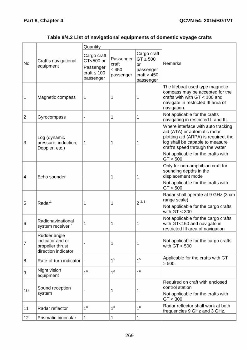
Part 8, Chapter 4 QCVN 54: 2015/BGTVT
269
Table 8/4.2 List of navigational equipments of domestic voyage crafts
No Craft’s navigational equipment
Quantity
Remarks
Cargo craft GT<500 or
Passenger craft 100 passenger
Passenger craft 450 passenger
Cargo craft GT 500 or passenger craft > 450 passenger
1 Magnetic compass 1 1 1
The lifeboat used type magnetic compass may be accepted for the crafts with with GT < 100 and navigate in restricted III area of navigation.
2 Gyrocompass - 1 1 Not applicable for the crafts navigating in restricted II and III.
3 Log (dynamic pressure, induction, Doppler, etc.)
1 1 1
Where interface with auto tracking aid (ATA) or automatic radar plotting aid (ARPA) is required, the log shall be capable to measure craft’s speed through the water
Not applicable for the crafts with GT < 500
4 Echo sounder - 1 1
Only for non-amphibian craft for sounding depths in the displacement mode
Not applicable for the crafts with GT < 500
5 Radar1 1 1 2 2, 3
Radar shall operate at 9 GHz (3 cm range scale)
Not applicable for the cargo crafts with GT < 300
6 Radionavigational system receiver 4
1 1 1 Not applicable for the cargo crafts with GT<150 and navigate in restricted III area of navigation
7
Rudder angle indicator and or propeller thrust direction indicator
- 1 1 Not applicable for the cargo crafts with GT < 500
8 Rate-of-turn indicator - 15 15 Applicable for the crafts with GT 500.
9 Night vision equipment
16 16 16
10 Sound reception system
- 1 1
Required on craft with enclosed control station
Not applicable for the crafts with GT < 300
11 Radar reflector 18 18 18 Radar reflector shall work at both frequencies 9 GHz and 3 GHz.
12 Prismatic binocular 1 1 1

QCVN 54: 2015/BGTVT Part 8, Chapter 4
270
No Craft’s navigational equipment
Quantity
Remarks
Cargo craft GT<500 or
Passenger craft 100 passenger
Passenger craft 450 passenger
Cargo craft GT 500 or passenger craft > 450 passenger
13 Aneroid barometer 1 1
14 Inclinometer 1 1 1
15 Marine chronometer 1 1 1
16 Topwatch 1 1 1
17
Electronic chart display and information system (ECDIS)
1 1 1
18 Automatic identification system
(AIS)9 1 1 1
Type B (Not applicable for the cargo crafts with GT < 500 )
1 At least one radar shall be equipped with automatic radar plotting or auto tracking aid suitable for craft’s speed. 2 The second radar shall operate at 3 GHz (10 cm range scale). 3 Where two radars are required, they shall be independent of each other. 4 The radionavigational system used shall be accessible at all times during the intended voyage. 5 The rate-of-turn indicator is required for craft of less than 500 gross tonnage if the test according to Annexes 3 and 9, Chapter 19 of the International Code of Safety for High-Speed Craft, 2000, shows that the turn rate can exceed safety level 1. 6 Where navigation of crafts in dark time, cargo crafts with GT < 500 may be permitted to navigate in dark time without night vision equipment if craft operates only in displacement mode. 7 Voyage data recorders shall be installed on cargo craft of more than 3000 gross tonnage. 8 To be installed on any craft of 150 gross tonnage and less. 9 For existing passenger ship shall be installed not later than 31 Dec, 2016.
4.3.2 Source of power
1 Navigational equipment required by this Part shall be supplied from the main and emergency sources of electrical power in compliance with the requirements of Part 4 Section II of QCVN 21: 2015/BGTVT.
2 Each navigational instrument indicated in Table 8/4.1 and 8/4.2 and requiring electrical power shall be supplied from the navigational equipment switch- board by separate feeders. Power supply to switch board busbars shall be provided from the main switchboard and from the emergency switchboard by two separate feeders.
3 Magnetic compasses shall be illuminated from the main and emergency sources of electrical power.
4.3.3 Spare parts
1 Spare parts for all navigational instruments shall be provided in accordance with 5.2.5 Section II of QCVN 42: 2015/BGTVT.
The number of spare parts may be changed on agreement with the VR, depending on navigational conditions and duration of the voyage.

Part 8, Chapter 4 QCVN 54: 2015/BGTVT
271
4.3.4 Night vision equipment
For navigation of high-speed craft in dark time, they shall be fitted with night vision equipment.
4.3.5 Craft control stations
1 All control functions of the craft when under way in any mode shall be exercised from the craft control station at the navigating bridge.
2 The craft control station shall be positioned in the upper part of the superstructure or be raised above the upper deck. The operating compartment shall be fitted with windows around the periphery to provide view all round the horizon when at sea and in manoeuvring the craft to a berth. Where all-round view is not provided, two control stations shall be arranged.
At least one exit to the craft’s side or stern shall be provided at the craft’s operating compartment. Besides, the operating compartment shall communicate with interior spaces. Arrangements shall be made to prevent passengers from entering the operating compartment.
3 Blind sectors shall be as few as possible. The total arc of blind sectors from right ahead to 22.5 deg abaft the beam on either side shall not exceed 20 deg. Each individual blind sector shall not exceed 5 deg and the clear sector between two blind sectors shall not be less than 10 deg. The view of the sea surface from the control station, when the navigators are seated, shall not be obscured by more than one craft length forward of the bow to 90 deg on either side, irrespective of the craft draught, trim and deck cargo.
4 The control station of the craft shall be, as far as possible, such as to ensure visual observation for the navigators and utilization of leading marks astern of the craft.
5 The number of workstations for personnel on watch in the craft control station shall be sufficient to normally maintain the watch and steer the craft. The required vision of the surroundings from each workstation sufficient for the operating personnel to perform their duties shall be provided.
6 The number of workstations and their arrangement depending on a possibility of all-round view, procedure of maintaining the watch by a navigator, helmsman, craft engineer and radio operator as well as on the extent of craft automation may be different and are subject to special consideration by the VR.
7 Where a docking station is provided for docking the craft, the field of vision from the docking workstation shall permit one navigator to safely manoeuvre the craft to a berth.
8 If separate workstations for supervision of engine performance and use of the radio equipment are placed in the operating compartment, the location and use of these workstations shall not interfere with primary functions in the operating compartment.
9 Each workstation shall be equipped with a seat, control panels with all necessary controls for the officer in charge to perform all the prescribed functions.
10 Seats shall be comfortable and so positioned that in the operational mode each operating crew member could be seated facing right ahead. The height of the seat shall be adjustable so that, in addition to the view referred to in -3, all indicators, controls and alarms referred to -16 could be easily used.
11 Seats shall be provided with safety belts and permanently attached in the most convenient position for the personnel in charge which shall not be changed during the craft operation.

QCVN 54: 2015/BGTVT Part 8, Chapter 4
272
The operating crew members, with the seats suitably adjusted and safety belts correctly worn, shall be able to perform the operations referred to in -10. Subsequent change of seat position to operate any control shall not be acceptable. Exception may be made only in respect of controls which are required on very rare occasions and which are not associated with the need for safety restraint.
12 A table suitable for chart work and record keeping in a logbook at the workstation shall be of a size sufficient for keeping nautical charts and publications thereon. The table shall be so placed that the navigator could work with charts and publications not leaving the seat. No table is necessary where an electronic chart display system is available on board.
13 The dimensions of the table at the workstation shall be not less than:
(1) 760 mm in width;
(2) 660 mm in depth.
14 The arrangement of the equipment in the control station is subject to special consideration by the VR.
15 Where an automatic steering aid is provided, a chart table may be positioned beyond the workstation but close thereto. In such case the officer in charge may temporarily leave the seat.
16 The following devices and instruments shall be located at each workshop in the control station:
(1) Levers to control main engines direction and speed of rotation or engine telegraph hand levers;
(2) Hand levers, buttons or wheels of directional control systems, i.e. steering engines, foils, flaps, steerable propellers, jets, yaw control ports, side thrusters, differential propulsive thrust, variable geometry of the craft or its lifting-system components, aerial or water rudders, lift fans, etc.;
(3) Main engine rotational speed and direction indicators, course indicators, rudder angle indicators, position indicators of foils, flaps, steerable propellers, jets, yaw control ports, side thrusters, differential propulsive thrust, variable geometry of the craft or its lifting-system components, aerial or water rudders, lift fans, etc.;
(4) Alarms on failures in engines, control devices and systems referred to in 4.3.5-16(1), 4.3.5-16(2) and 4.3.5-16(5);
(5) Craft’s automatic stabilization system control station and automatic safety control station;
(6) Hand controls of safety device of automatic stabilization system of craft modes;
(7) Illuminated indicator panels and sound alarms of the warning and alarm systems of craft automated machinery, systems and arrangements;
(8) Illuminated indicator panels and sound alarms of fire detection systems;
(9) A device for remote starting of fire-extinguishing systems;
(10) Navigation light boards and associated signalling systems;
(11) Navigational equipment required by this Chapter;
(12) Radio equipment required by Chapter 3;

Part 8, Chapter 4 QCVN 54: 2015/BGTVT
273
(13) Light and sound signalling devices on failures in ventilation system for special-category spaces;
(14) Switches for remote stopping of fans in accommodation, service, machinery spaces and in special-category spaces;
(15) Instruments for measuring temperature, pressure, level of liquid, voltage, load and other essential parameters of craft propulsion machinery and arrangements;
(16) Remote arrangements for stopping flammable liquid transfer pumps and fire-extinguishing systems control;
(17) Alarms on high water level in drained spaces;
(18) Any other instruments, arrangements, controls, including those for emergency purposes, which may be required depending on the craft structure.
17 The equipment referred to in -16 shall be arranged on consoles, bulkheads, desks, etc. It shall have such design and size of light and digital indicator scales, signal lamps, controls, and be so mounted and illuminated that operating personnel can easily view the instruments and operate the controls without leaving their seats in all possible service conditions.
18 All alarm, indication and monitoring instruments referred to in 10.16, and controls shall be logically grouped according to their function. The alarm, indication and monitoring instruments shall be clearly marked with any limitation if this information is not otherwise clearly presented to the operating crew. The instrument panels forming the emergency control for the monitoring of the fire-fighting systems and launching of liferafts, etc. shall be grouped and be separate. The instruments shall not be rationalized by sharing functions or by interswitching.
19 The alarm, indication and monitoring instruments shall be so designed as to be plainly visible at any level of lighting. Glare and reflections from the instruments shall not interfere with normal work of the operating personnel at nighttime.
20 The surfaces of the alarm, indication and monitoring instruments, and console tops shall have dark, matt, glare-free colours.
21 Only the most essential equipment shall be arranged in front of the operating crew members facing right ahead, provided their attention and observation of the surroundings is not prevented.
Where indications of the alarm, indication and monitoring instruments and visual information on the displays of navigational equipment shall be used by more than one person, they shall be located for easy viewing by all users concurrently. If this is not possible, the instrument or display shall be duplicated.
22 Where maintaining watch and radio equip- ment control at workstations are difficult due to arrangement of the radio equipment used, a special workstation for the radio operator, in addition to the workstations referred to in -5, shall be provided. The VHF radio installation control desk shall be positioned in all cases at the workstations referred to in -5.
23 Means to communicate between the operating compartment and spaces containing essential machinery, such as propulsion machinery, emergency steering positions, etc., shall be provided
24 A portable microphone shall be provided in the operating compartment for making public address and safety announcements to all areas to which passengers and crew have access and through which escape paths are routed, and to all survival craft embarkation stations.

QCVN 54: 2015/BGTVT Part 8, Chapter 4
274
25 The operating compartment shall be equipped with adequate temperature and ventilation control systems.
26 An adequate level of lighting shall be provided in the operating compartment to enable the operating personnel to efficiently perform their tasks both at sea and in port. Red light shall be used to maintain dark adaptation whenever any items of equipment other than the chart table require local illumination in the operational mode.
27 Lighting in the operating compartment and noise generated by the instruments installed in the operating compartment shall not produce any interference for navigation.
28 Where provision is additionally made to control the craft from control stations other than the craft’s operating compartment referred to in 10.2, the alarm, indication and monitoring instruments and controls shall be switched over to operation from other stations only from the craft’s operating compartment.
29 Sockets supplied from the emergency source of electrical power for connection of a portable lamp which shall be permanently kept in the craft control station shall be provided in the craft.
30 Where the craft control station is equipped with a combined craft control panel, one shall be guided by the provisions of this Section, those of 5.12 Section II of QCVN 42: 2015/BGTVT and Part 4 Section II of QCVN 21: 2015/BGTVT and their amendments.
31 Divisions between windows shall be kept to a minimum. No division shall be installed immediately forward of the officer in charge and helmsman workstations.
32 The arrangement of the control station windows and the curvature of their surface shall be such that no glare, reflections or distortions are produced which might result in navigation errors. Neither polarized or tinted window glass shall be fitted. The windows shall be angled from the vertical plane top out to not less than 10 deg but not more than 25 deg to reduce unwanted reflections. Windows shall be made of a material which will not break into dangerous fragments if fractured.
33 Front windows and, depending of configuration of the control station, other window shall be provided with means for wiping, heating and air blowing of the windows. The means shall be so arranged that no reasonably probable single failure can result in a reduction of the cleared field of vision from the operating compartment.
34 The design and software of the equipment arranged in the operating compartment shall be such as to prevent their use for purposes other than navigation, communication and other functions essential to the safe operation of the craft.
4.4 Operational requirements for navigational equipment
4.4.1 General requirements
1 All navigational instruments and devices that are part of the craft’s navigational equipment shall have technical characteristics not lower than those required by this Chapter of the Regulation, and they shall be arranged so that safety of navigation is ensured in the area and under conditions for which the craft is intended.
2 All navigational equipment required by this Part of the Regulation as well as the navigational aids to be installed on high-speed craft in addition to those required shall comply in respect of their technical characteristics with the requirements of 5.5 Section II of QCVN 42: 2015/BGTVT, provided they are not specially defined in this Chapter, and with

Part 8, Chapter 4 QCVN 54: 2015/BGTVT
275
special requirements dictated by high speeds of the craft between 30 and 70 knots. Such requirements, if they are not set forth below, are subject to special consideration by VR.
4.4.2 Radars
1 The radars installed on crafts on or after 1 July 2008 shall comply with the requirements of 5.5.7 Section II of a QCVN 42: 2015/BGTVT. The number of the radars required shall comply with the requirements of Table 8/4.1 and 8/4.2 and their performance characteristics, depending on gross tonnage, shall comply with the requirements of Table 5.5.7-2 Section II of QCVN 42: 2015/BGTVT. In this case, a speed of aerial rotation shall be at least 40 rpm. The radars installed on crafts before 1 July 2008 shall comply with the performance standards given from -2 to -15 below.
2 The radar shall be capable of providing a clear indication of coastlines, surface objects and locating their position giving continuous uninterrupted all round scanning of the horizon under true and relative motion presentation. All radars operating in 3 cm range shall have horizontally polarized radiation.
3 Where the radar antenna is mounted at a height of 7.5 m above sea level, the radar display unit shall be capable of giving clear indication of surface objects, such as navigation buoys having an effective echoing area of 10 m2 at 2.5 nautical miles in the absence of clutter. These objects shall be clearly seen at the radar display at a minimum distance of 35 m and up to a distance of one nautical mile without changing of controls position except the range scale switch. The above-mentioned requirements shall be met at rolling and pitching motions up to 10°.
4 The radar display shall have an effective diameter of at least 250 mm without any outside magnifying instruments. The display shall provide multi-colour presentation and adjustment of its brightness. Provision shall be made for the quick change of colour presentation for better observation both in daytime and at night.
The display unit of the radar shall be provided with the following set of range scales: 0.25; 0.5; 0.75; 1.5; 3; 6; 12 and 24 nautical miles. Additional range scales may be provided. There shall be indicated not less than two fixed electronic range rings on the range scales 0.25, 0.5 and 0.75 nautical miles, and up to six rings on the other scales.
The nominal value of the range scale and distance between fixed electronic range rings shall be clearly indicated on the working part of the display unit.
Besides, variable electronic range ring with a numeric read-out of the range shall be provided.
The fixed and the variable range rings shall ensure the accuracy of measurement of the object range with an error not exceeding 1 per cent of the maximum range of the scale in use, or 30 m, whichever is the greater.
Provision shall be made for off-set of the centre of scanning at least for 50 per cent but not more than for 75 per cent from the range scale used.
It shall be possible that brightness of the fixed and a variable range rings be varied up to their total removal from the display.
5 The display unit of the radar shall have an electronic direction sighting device intended for determination of the direction to any target which mark appears on the screen. The error of measurement of the direction to a target which is on the edge of the screen shall not exceed ±1°.
Provision shall be made for at least two lines of the direction sighting device.
QCVN 54: 2015/BGTVT Part 8, Chapter 4
276
After installation on the craft and adjustment the accuracy of measurement of the direction to the target shall be maintained without any adjustments independently of the craft movement in magnetic fields of the Earth.
6 The craft heading shall be indicated on the screen by means of electronic course mark in the form of a line with a maximum error ±1°. The width of the course mark at the edge of the display face shall not exceed 0.5°.
The possibility shall be provided for temporary removal of the course mark image using a switch with automatic reset to “on“ position.
7 Provision shall be made for indication on the screen of the display unit, along with radar information, of the planned route in graphical form, i.e. route points and segments of straight lines connecting them. The source of graphical information shall be clearly indicated.
The possibility shall be provided for displaying target motion trajectories in the form of trails created by marks of targets due to the screen artificial afterglow.
Trails shall be relative or true, true trails shall be stabilized relative to the water or ground.
8 The radar shall have a resolution that, in the absence of clutter, provides:
(1) On 1 mile range scale and less, separate indication of two objects with an effective target area of 10 m2 located on the same azimuth at the distance equal to 50 — 100 per cent of the range nominal value of the range scale used and distant not more than 35 m from each other;
(2) On 1.5 mile range scale and less, separate indication of two objects with an effective target area of 10 m2 located at the same distance within 0.5 to 1 mile limits and not more than 2.5° from each other for radar operating in 3 cm range and not more than 4° for radar operating in 10 cm range.
9 Devices shall be provided to eliminate clutter created by reflections from precipitation, clouds, sand storms and sea surface.
Provision shall be made for smooth manual regulation of such devices and for switching off those signal processing devices which may prevent reflection from the radar beacon responder.
10 The radar shall be ready for operation within 4 min upon being switched on. The “stand-by“ position shall be provided after which the radar may be set in the “switched on“ position within 15 s.
11 Means shall be provided to check and determine a substantial drop in performance relative to the manufacturer calibration standard and to check that the equipment is correctly adjusted in the absence of targets indication on the screen of the display unit.
12 The radar shall be capable of receiving information signals from gyrocompass, log, receivers of radionavigation systems. Alarms on absence or decreasing of quality of information signals from the above-mentioned equipment shall be duplicated.
13 The radar shall be capable to provide all- round view over the entire horizon in the relative motion mode. The accuracy of alignment with a course information source shall be within ±0.5° with a rotation rate of 20°/s.
The radar shall operate properly in the absence of a signal from a course information source.
It is recommended to provide the possibility of radar operation in the true motion mode.

Part 8, Chapter 4 QCVN 54: 2015/BGTVT
277
14 Provision shall be made in the radar for clockwise continuous and automatic scan through 360° of azimuth. The scan rate shall be not less than 40 rpm.
The antenna shall be capable to operate with a relative wind velocity up to 100 knots.
15 Controls shall be readily accessible and easily recognizable.
In case symbols are used for their indication, they shall correspond to commonly used symbols for identification of navigation marine radar controls. The navigator shall be able to switch on and operate the radar from his workstation, when seated.
4.4.3 Gyrocompasses
1 In craft whose speed is below 30 knots the gyrocompass shall comply with the requirements of 5.5.3 Section II of QCVN 42: 2015/BGTVT. For craft having speeds between 30 and 70 knots the gyro- compass shall meet the requirements given below.
2 The gyrocompass positioned on a horizontal and stationary base on board the craft operating in latitudes of up to 70 deg shall comply with the following requirements:
(1) The gyrocompass shall be brought into alignment with meridian within 6 hours;
(2) The steady-state error at any course shall not exceed ±0.75° x secant latitude, the root mean square value of the difference between individual course indications and the mean value of the course shall be not less than ±0.25° x secant latitude;
(3) The permissible error from one run-up to another shall be within ±0.25° x secant latitude.
3 In latitudes between 70 °N and 70 °S, when the craft operates within the latitude range 10°, the gyrocompass shall comply with the following requirements:
(1) Under rolling and pitching harmonic motions with a period of 6 to 15 s, amplitude of 5° at maximum accelerations of 22 m/s2 the gyrocompass shall be brought into alignment with meridian within 6 h;
(2) The steady-state error of the master compass readings, from one run-up to another, under service conditions associated with variations of the magnetic field and environmental temperature shall be within ±1° x secant latitude;
(3) The residual error at a straight course (after correction for speed and course at a speed of 70 knots shall not exceed ±0.25° x secant latitude;
(4) The maximum error of readings due to a rapid acceleration of the craft up to a speed of 70 knots shall not exceed 2;
(5) The error of readings due to rapid alteration of course of 180° at a turn angular speed 20°/s and speed of 70 knots shall not exceed ±3°;
(6) Steady and variable errors of the indications caused by harmonic rolling up to 20°, pitching up to 10° and yawing up to 5° with a period from 6 to 15 s and the maximum horizontal acceleration not more than 1 m/s2 at any course (in particular, 45°, 90° and 315°) shall not exceed ±1° x secant latitude;
(7) Gyrocompasses shall operate reliably as it is required in 5.5.1-2 Section II of QCVN 42: 2015/BGTVT; the maximum error shall not exceed ±1°;
(8) The maximum divergence in readings between the master compass and repeaters shall not exceed ±0.5° under any operational conditions;
(9) The respond rate of the gyrocompass follow-up system shall be not less than 20°/s.

QCVN 54: 2015/BGTVT Part 8, Chapter 4
278
4 Gyrocompass shall be provided with a compass card or analogue repeater for indication of course information, visual bearing taking devices as well as a corrector used for correction of compass readings in respect of craft speed and latitude.
The device shall be calibrated in 1° or 1/10° increments. Digital markings shall be indicated in every 10° clockwise from 0 to 360°.
In addition, a digital indicator may be provided. The course shall be presented on the digital indicator in the form of three figures (the fourth figure may indicate tenths of a degree).If a gyrocompass with a digital indicator is used it shall include a turn indicator.
5 The remote indication system of the gyrocompass shall be designed so as to ensure simultaneous operation of gyrocompass own repeaters, course recorder, as well as repeaters fitted in other navigational equipment.
6 A course recorder shall be capable of recording craft course in respect of time with an accuracy ±1%.
7 Provision shall be made for a visual and/or audible indication of gyrocompass readiness for operation as well as audible and visual alarms on power supply failure or failures in the compass system.
8 The compass shall be supplied with electric power from the main and emergency sources of power with automatic switching-over.
9 Gyrocompass shall be provided with devices for correction of error due to a rapid alteration of craft’s speed and influence of the magnetic field in different latitudes.
10 Appropriate interfaces shall be provided to transfer of the course information to other navigation equipment, such as radars, ARPA, ATA, ETA, AIS, ECDIS, voyage data recorder, craft’s heading control system or track control system.
4.4.4 Craft heading control systems (automatic steering devices)
Craft heading control systems (automatic steering devices) shall be designed and manufactured according to A.822(19).
4.4.5 Night vision equipment
1 Night vision equipment shall be designed for continuous operation during night time (from sunset to dawn).Night vision equipment shall be designed so that it detects objects above water surface at a given distance from the ship which threaten shipping, such as small unlit boats, floating logs, oil drums, containers, buoys, ice, whales, etc. and shows them on the screen.
Night vision equipment shall determine position of such objects in relation to the ship and display them in real time.
2 After the equipment has been switched on it shall be operational in less than 15 min.
3 Night vision equipment shall detect the standard test target at a distance of at least 600 m with a minimum probability of 90 per cent under mean starlight conditions without clouds and without moon. The standard target shall be a black metal object of such a size that when at least 50 per cent is immersed, 1.5 m long and 0.5 m high remains above water at right angles to the desired direction of detection. The standard test target shall stay at least 24 h in water before testing.
4 Equipment shall enable detection and display of objects staying in:
- Horizontal field of view shall be at least 20°, 10° on either side of the bow;

Part 8, Chapter 4 QCVN 54: 2015/BGTVT
279
- Vertical field of view shall be at least 12°, meanwhile observation of the horizon shall be provided;
- Other sectors of view may be provided. They shall be activated by special non-locking switch which returns to the required field of view when released;
- Watch navigator working place shall be equipped with the visual indication of the sector of view in use.
5 The axis of the field of view of the equipment shall be capable of being moved at least 20° horizontally to either side. The system shall be capable of panning at a minimum angular speed of 30°/s. This shift shall be made by a single control and the equipment shall be capable to revert automatically to the initial sector of view to the ahead position at a minimum angular speed of 30°/s.
6 The elevation axis of the field of view shall be capable of being adjusted by at least 10° to compensate for the trim of the craft.
7 The heading marker of the craft shall be indicated on the display with an error not greater than ±1°.
A visual indication of relative bearing with an error of not greater than ±1° shall be provided, it shall appear while the axis of horizontal field of view has shifted to the corner when the heading marker disappears from the display.
8 Sensor of the night vision equipment shall be designed so that it operates at the following weather conditions:
- Pitching and/or rolling up to 10°;
- Relative velocity of the head wind and / or true wind up to 100 knots;
- Icing;
- Spattering or thumbing of the sensor lens.
It shall be possible to clean sensor lens from the ship control station.
If the sensor rotating mechanism fails, it shall be possible to fix it in the forward direction.
9 The equipment shall be designed so that to exclude or reduce to minimum such hindrances like dazzle or reflection of light, glow or other visual interferences.
10 Night vision equipment shall include a visual indication of any failure.
11 Number of controls shall be minimal. Clear notes and/or conventional symbols shall indicate their purpose.
12 Number of controls shall be minimal. Clear notes and/or conventional symbols shall indicate their purpose.
It is not recommended to use controls of dual purpose as well as to apply Menus for operation of equipment.
13 Controls shall be clearly visible in darkness. If they are fitted with lighting it shall be adjustable.
14 Information display of night vision equipment shall not twinkle or blind craft operating crew. Screen diagonal shall be sufficient to show image of at least 180 mm by diagonal.
15 If any function of the night vision equipment is realized by means of software, it shall:
- Display the user interface status;

QCVN 54: 2015/BGTVT Part 8, Chapter 4
280
- Contain self-description of the functions implemented by means of software;
- Be protected from casual and/or unauthorised changes;
- Meet requirements of Chapter 3.
16 If manufacturer recommends to carry out maintenance works of the equipment regularly, it shall be fitted with the elapsed operation time counter.

Part 9, Chapter 1 QCVN 54: 2015/BGTVT
281
PART 9 NAVIGATION BRIDGE VISIBILITY
CHAPTER 1 GENERAL
1.1 General
1.1.1 Application
Navigation brigde visibility of crafts is to comply with requirements in Part 12 Section II QCVN 21: 2015/BGTVT.
Part 10, Chapter 1 QCVN 54: 2015/BGTVT
283
PART 10 SPECIAL REQUIREMENTS FOR CRAFTS ENGAGED IN
INTERNATIONAL VOYAGE
CHAPTER 1 GENERAL
1.1 General
1.1.1 Application
In addition to the requirements specified in Part 1 to Part 8 of this Regulation, crafts engaged on international voyages are to be complied with the requirements of MSC.97(73), as may be amended, in its entirety or other technical requirements which VR considers to be equivalent to the said requirements.
Section III QCVN 54: 2015/BGTVT
285
III REGULATIONS ON MANAGEMENT
1.1 General
Upon the compliance of crafts with requirements in this Regulation, VR will assign the class to crafts with class notations as specified in 1.2 of this Section.
1.2 Class Characters and Notations
1.2.1 Classification Characters
1 Class of craft is distinguished with following basic class characters:
(1) VR: Showing that the design of the craft was approved by VR and the construction of the craft was carried out under supervision of VR;
(2) VR: Showing that the construction was carried out under supervision of a Classification Society authorized or/and recognized by VR.
(3) () VR: Construction without supervision of VR or under supervision of a Classification Society not recognized by VR.
2 Class notation of Hull and Machinery Installations are as follows:
Class notation of Hull is H; class notation of Machinery Installation is M. These class
notations are affixed to basic class characters, e.g., VRH; VRM.
3 Notation of High speed craft is HSC which is affixed to class notation of Hull and Machinery
Installations, e.g., VRH HSC; VRM HSC.
1.2.2 Class notations
1 For ship complying with addition requirements and/or those exempted from requirements related to the subjects specified in 1.2.2 này, complied with the requirements in this Regulation, appropriate addition notations shall be affixed to the Classification Characters as follows.
2 Class notation of Hull
Class notation of hull may be affixed to the Classification Characters as follows:
VRH HSC “restricted area of navigation (specified in (1))” “structure material for main hull (specified in (2))”; “hull construction and equipment (specified (3))”; “ international voyage (specified (4))”.
(1) For ships classed to be engaged in restricted services, an appropriate notation is affixed to the Classification Characters as follows:
(a) For ships navigating in restricted area specified in 1.2.2-57 Section I: I;
(b) For ships navigating in restricted area specified in 1.2.2-58 Section I: II;
(c) For ships navigating in restricted area specified in 1.2.2-59 Section I: III.
QCVN 54: 2015/BGTVT Section III
286
(2) For ships that use materials other than steel as the structural material for the main hull in accordance with the provisions of 1.2.1, Part 2 Section II, an appropriate notation is affixed to the Classification Characters as follows:
(a) For ships made of aluminium alloy: Aluminium Alloy (abbreviated to AL);
(b) For craft made of fibre reinforced plastic: FRP (abbreviated to FRP);
(c) For craft other than those specified in above, a notation deemed appropriate by VR may be affixed.
(3) Hull Construction and Equipment
(a) For craft of catamaran or trimaran and complying with relevant requirements, the notation of Catamaran (abbreviated to CAT) or Trimaran (abbreviated to TRI) is affixed;
(b) For craft intended for the carriage of passengers and complying with the relevant requirements of this Regulation, the notation of Passenger (abbreviated to P) is affixed;
(c) For ships having others characteristic of hull construction and equipment, an appropriate addition class notation shall be affixed as specified in 2.1.7 Part 1A Section II of QCVN 21: 2015/BGTVT.
(4) For ship navigating in international voyage complied with the requirements of MSC.97(73), in addition to class notation as specified from (1) to (3) above, classification character shall be affixed the notation: IMO.
3 Machinery installations
Machinery installations may be affixed the notations as specified in 2.1.3-1(2) Part 1A
Section II of QCVN 21: 2015/BGTVT.
4 Unless otherwise specified above, for ships deemed necessary by the VR, an appropriate notation may be affixed to the Classification Characters the notations as specified in 2.1.3 Part 1A Section II of QCVN 21: 2015/BGTVT.
1.3 Regulation on Survey
Sea-going high speed craft is to be subjected to class surveys as specified in Part 1B Section II of this Regulation.
1.4 Certification
1.4.1 Certificates issue according to this Regulation
1 Classification certificate, High speed craft Safety Certificate, Load Line Certificate are issued when the ships completed classification survey before putting into service or special survey completion.
2 In addition to certificate as specified in -1, Permit to Operate High speed craft is issued to ship navigating international voyage complied with MSC.97(73).
3 The certificates from -1 to -2 shall be valid with period not exceeding 5 years from the date of classification survey completion before putting into service or date of completion of special survey and those shall be verified annually.

Section III QCVN 54: 2015/BGTVT
287
4 Availability of survey results as specified in Part 1B Section II of this Regulation is the ground for Seaworthiness Certificate issuance. The Seaworthiness Certificate shall be valid with period not exceeding the date of expiry of the next survey.
1.4.2 Certification procedure
Certification procedure shall be carried out according to Circular 32/2011/TT-BGTVT similar to sea-goings ships.
1.5 Technical registration
Craft technical registration shall be carried out according to 3.1 Section III of QCVN 21: 2015/BGTVT.
1.6 Survey request
1.6.1 Survey request letter
1 Classification survey
Classification survey shall be carried out by VR after receiving the survey request letter from shipowner or ship builder.
2 Class maintenance survey
Class maintenance survey shall be carried out by VR after receiving survey request letter from shipowner, ship's master or representative of shipowner.
1.7 Class withdrawal and invalid of Classification certificate
1.7.1 Class withdrawal
1 VR will withdraw the class and notify the same to the owner of a ship when:
(1) It is requested by the owner of the craft;
(2) VR recognizes that the ship can no longer be used because it was scrapped, sank, etc.;
(3) The Surveyors report that the ship has not complied with survey requirements specified in 1.1.2 Part 1B Section II of this Regulation and VR accepts the report;
(4) The ship is not subjected to the survey defined in 1.1.2 Part 1B Section II of this Regulation;
(5) Survey fees are not paid.
2 In the cases of -1(4) or -1(5) above, VR reserves the right to suspend the class for a specific period as provided separately.
1.7.2 Reclassification
The owner of a ship may apply for the reclassification of the ship for which its class has been withdrawn. The class of such a ship will be determined by VR considering the present condition of the ship and the Classification Character at the time the class was withdrawn.
QCVN 54: 2015/BGTVT Section III
288
1.7.3 Invalidation of Certificate of Classification
1 The validity of a Certificate of Classification shall cease to be valid in the following cases:
(1) If the ship's class is terminated or her registration is deleted as specified in 1.7.1-1 above;
(2) If after an accident, VR has not been notified of and the ship has not been subjected to Occasional Survey by the surveyors at port where the accident took place or at the first port of call if the accident took place at sea;
(3) If alterations have taken place in the construction and/or if any change has been made in the equipment without VR's approval or without notification to VR;
(4) When repair of supervised items of a ship has been performed without the agreement and/or supervision by VR;
(5) When a ship navigates with a draught exceeding that assigned by VR for specific conditions as well as in case of operation of a ship in conditions which do not comply with the requirements for assigned class of a ship or the restrictions specified by VR;
(6) If the prescribed specific requirements which during previous survey were conditions for assignment or confirmation of the class have not been fulfilled within the specified period;
(7) If the process of surveying the ship by VR has been suspended by shipowner's initiative or through his fault;
(8) When the ship has been taken out of service for a long period (more than 3 months) for fulfilment of VR' requirements (except the case when a ship is under repair for these purposes).
1.8 Documentation
1.8.1 Storage, Reissue and return of certificates
1 The master of a ship is to keep a Certificate on board the ship and present the same to VR upon request.
2 The owner or master of a ship is to request the VR without delay to reissue a Certificate when the same:
(1) Certificate is lost or soiled;
(2) the particulars described in the same are changed.
3 The owner or master of a ship is to return the old Certificate to VR immediately if the Certificate has been issued after completion of special survey or reissued under -2, except when the Certificate was lost.
4 The owner or master of a ship is to return the old Certificate to VR immediately if the Certificate has been issued under the provisions of 1.7.1.
5 The owner or master of a ship is to, when a lost Certificate is found after reissuing the same under -2 above, return the found certificate to VR immediately.
6 Survey Document storage

Section III QCVN 54: 2015/BGTVT
289
All documents issued by VR for ships including test/inspection report (ground to issue related certificates), certificates, material and product certificate are to be kept and
maintained on board and ready to present to surveyor as requested.

Section IV QCVN 54: 2015/BGTVT
290
IV RESPONSIBILITIES OF ORGANIZATIONS, INDIVIDUALS
1.1 Responsibilities of shipowners, ship operators, ship designers, ship yards, ship repairing yards
1.1.1 Shipowners, Ship Operators
To apply all relevant requirements in this Regulation for crafts being built, converted, renovated, repaired and during operation in order to ensure and maintain technical condition of crafts.
1.1.2 Ship Designer
1 To design ships in compliance with relevant requirements of this Regulation.
2 To prepare sufficient design documents as required and submit for approval in compliance with requirements of this Regulation.
1.1.3 Ship Yards, Ship Repairing Yards
1 To be capable in terms of warehouse, manufacturing shop, building facilities etc. and competent manpower to meet requirements for ship building and repairing.
2 To comply, in addition to approved designs, with standards of quality, safety and environmental protection while building, repairing, renovating ships.
3 To undergo VR’s supervision on the quality, safety and environmental protection during construction, converting, renovation and repairing of ships.
1.2 Responsibilities of Vietnam Register
1.2.1 Approval of ship design, survey
To arrange of surveyors with proper abilities and standards to carry out design approval, supervision during new building, conversion, reproduction and repair comply with requirements as specified in this Regulation.
1.2.2 Instructions for application
VR is to give instructions for application of requirements of this Regulation to ship designers, shipowners, ship yards and ship repair yards, inspection offices of VR and ship operators and management companies.
1.2.3 Amendment to this Regulation
VR is to make proposal to the Ministry of Transport for the Amendment to this Regulation on annual basis where found necessary.
1.3 Responsibilities of the Ministry of Transport
Ministry of Transport is responsible to verify on the regular or random basis the implementation of relating organizations in compliance with this Regulation.
Section V QCVN 54: 2015/BGTVT
291
V IMPLEMENTATION
1.1 VR has responsibility o manage survey system throughout the country of Vietnam to carry out surveys and supervision for classification of high speed craft. To organise the printing, dissemination and instructions for application of these Regulations for organizations and individuals which are the objectives of application of these Regulations.
1.2 In case of inconsistency, the requirements of these Regulations prevail over the requirements of others.
1.3 In case of referenced documents in this Regulation are amended, added or replaced, the amended, added or replaced documents shall be applied.
1.4 For international sea going ship, in case of inconsistency between the requirements of these Regulations and those of international conventions to which Vietnamese government is a member, the requirements of that international conventions prevail over the requirements of these Regulations.
1.5 Except from otherwise regulating the date of application for existing crafts, this Regulation and its amendments, additions are applied for craft at beginning stage of construction or date of the enforcement of Circular promulgating this Regulation.
Appendix A QCVN 54: 2015/BGTVT
292
APPENDIX A
METHODS RELATING TO THE INTACT STABILITY INVESTIGATION OF HYDROFOIL CRAFT
The stability of these craft should be considered in the hull-borne, transient and foil-borne modes. The stability investigation should also take into account the effects of external forces. The following procedures are outlined for guidance in dealing with stability
1.1 Surface-piercing Hydrofoils
1.1.1 Hull-borne Mode
1 The stability should be sufficient to satisfy the provisions of 1.3 and 1.4, Part 6 Section II of this Regulation.
2 Heeling Moment due to Turning
The heeling moment developed during manoeuvring of the craft in the displacement mode may be derived from the following formula:
20
R
VM 0.196 KG
L (kN.m)
Where:
RM :moment of heeling;
0V :speed of the craft in the turn (m/s);
:displacement (t);
L :length of the craft on the waterline (m);
KG :height of the centre of gravity above keel (m).
This formula is applicable when the ratio of the radius of the turning circle to the length of the craft is 2 to 4.
3 Relationship between the Capsizing Moment and Heeling Moment to Satisfy the Weather Criterion
The stability of a hydrofoil boat in the displacement mode can be checked for compliance with the weather criterion K as follows:
c
v
MK 1
M
Where:
cM : minimum capsizing moment as determined when account is taken of rolling;
vM : dynamically applied heeling moment due to the wind pressure.
4 Heeling Moment due to Wind Pressure
The heeling moment vM is a product of wind pressure vP the windage area vA and the
lever of the windage area Z.

Appendix A QCVN 54: 2015/BGTVT
293
Mv = 0.001PvAvZ (kN.m)
The value of the heeling moment is taken as constant during the whole period of heeling.
The windage area AV is considered to include the projections of the lateral surfaces of the
hull, superstructure and various structures above the waterline.
The windage area lever Z is the vertical distance to the centre of windage from the waterline and the position of the centre of windage may be taken as the centre of the area. The values of the wind pressure (in pascals) associated with Force 7 Beaufort scale, depending on the position of the centre of windage area.
(1) For sea-goings craft, vP is to be taken in Table A.1;
Table A.1 Typical Wind Pressures, 100 Nautical Miles from Land for Beaufort Scale 7
Z above water line (m) 1.0 1.5 2.0 2.5 3.0 3.5 4.0 4.5 5.0
Pv (Pa) 46 46 50 53 56 58 60 62 64
Note: These values may not be applicable in all areas
5 Evaluation of the Minimum Capsizing Moment in the Displacement Mode
The minimum capsizing moment is determined from the static and dynamic stability curves taking rolling into account.
(1) When the static stability curve is used, Mc is determined by equating the areas under the curves of the capsizing and righting moments (or levers) taking rolling into account, as indicated by Fig A.1, where z is the amplitude of roll and MK is a line drawn parallel to the abscissa axis such that the shaded areas S1 and S2 are equal.
cM = OM, if the scale of ordinates represents moments;
cM = OM × Displacement, if the scale of ordinates represents levers.
(2) When the dynamic stability curve is used, first an auxiliary point A should be determined. For this purpose the amplitude of heeling is plotted to the right along the abscissa axis and a point A' is found (see Figure A.2). A line AA' is drawn parallel to the abscissa axis equal to the double amplitude of heeling (AA' = 2 x z ) and the required auxiliary point A is found. A tangent AC to the dynamic stability curve is drawn. From the point A the line AB is drawn parallel to the abscissa axis and equal to 1 radian (57.3°). From the point B a perpendicular is drawn to intersect with the tangent in point E. The distance BE is equal to the capsizing moment if measured along the ordinate axis of the dynamic stability curve. If, however, the dynamic stability levers are plotted along this axis, BE is then the capsizing lever, and in this case the capsizing moment MC is determined by multiplication of ordinate BE (in meters) by the corresponding displacement in tonnes):
cM 9.81 BE (kNm)
(3) The amplitude of rolling z is determined by means of model and full-scale tests in irregular seas as a maximum amplitude of rolling of 50 oscillations of a craft travelling at 90° to the wave direction in sea state for the worst design condition. If such data are lacking the amplitude is assumed to the equal to 15°;

QCVN 54: 2015/BGTVT Appendix A
294
(4) The effectiveness of the stability curves should be limited to the angle of flooding.
1.1.2 Transient and foil-borne modes
1 The stability should satisfy the provisions of 1.4 and 1.5 of this Part 6, Section II.
(1) The stability in the transient and foil-borne modes should be checked for all cases of loading for the intended service of the craft.
(2) The stability in the transient and foil-borne modes may be determined either by calculation or on the basis of data obtained from model experiments and should be verified by full-scale tests by imposition of a series of known heeling moments by off-center ballast weights, and recording the heeling angles produced by these moments.
When taken in the hull-borne, take-off, steady foil-borne and settling to hull-borne modes, these results will provide an indication of the values of the stability in the various situations of the craft during the transient condition.
(3) The angle of heel in the foil-borne mode caused by the concentration of passengers at one side should not exceed 8°. During the transient mode the angle of heel due to the concentration of passengers on one side should not exceed 12°. The concentration of passengers should be determined by VR, having regard to the guidance given in Annex B.
2 One of the possible methods of assessing foil-borne metacentric height (GM) in the design stage for a particular foil configuration is given in Figure A.3
Fig A.1 Static Stability Curve
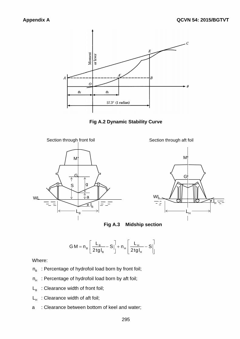
Appendix A QCVN 54: 2015/BGTVT
295
Fig A.2 Dynamic Stability Curve
B HB H
B H
L LG M n S n S
2tg l 2 tg l
Where:
Bn : Percentage of hydrofoil load born by front foil;
Hn : Percentage of hydrofoil load born by aft foil;
BL : Clearance width of front foil;
HL : Clearance width of aft foil;
a : Clearance between bottom of keel and water;
Section through aft foil
G
M
WL
HL
Hl
Fig A.3 Midship section
G
M
S g
a
Section through front foil
WL
Bl BL

QCVN 54: 2015/BGTVT Appendix A
296
g : Height of center of gravity above bottom of keel;
Bl : Angle at which front foil is inclined to horizontal;
Hl : Angle at witch aft foil is inclined to horizontal;
S : Height of center of gravity above water.
1.2 Fully submerged hydrofoils
1.2.1 Hull - born mode
1 The stability in the hull-born mode should be sufficient to satisfy the provisions of 1.3 and 1.6, this Part 6 Section II.
2 Paragraphs 1.1.1-2 to 1.1.1-5 of this Appendix are appropriate to this type of craft in the hull-born mode.
1.2.2 Transient mode
1 The stability should be examined by the use of verified computer simulations to evaluate the craft's motions, behaviour and responses under the normal conditions and limits of operation and under the influence of any malfunction.
2 The stability conditions resulting from any potential failures in the systems or operational procedures during the transient stage which could prove hazardous to the craft's waterline integrity and stability should be examined.
1.2.3 Foil-born mode
The stability of the craft in the foil-born mode should be in compliance with the provisions of 1.4, this Part 6, Section II. The provisions of paragraph 1.2.2 of this Appendix should also be applied.
1.2.4 Other requirements
Paragraphs 1.1.2-2 of this Appendix should be applied to this type of craft as appropriate and any computer simulations or design calculations should be verified by full-scale tests.

Appendix B QCVN 54: 2015/BGTVT
297
APPENDIX B
REQUIREMENTS FOR STABILITY OF MULTIHULL CRAFT
1.1 Stability criteria in the intact condition
A multihull craft, in the intact condition, should have sufficient stability when rolling in a seaway to successfully withstand the effect of either passenger crowding or high-speed turning as described in the following 1.1.4. The craft's stability should be considered to be sufficient provided compliance with this Appendix.
1.1.1 Area under GZ curve
The area ( 1A )under the GZ curve up to an angle should be at least:
o
1
0.055x30A
(m.rad)
Where is the least of the following angles:
(a) The downflooding angle;
(b) The angle at which the maximum GZ occurs; and
(c) o30 .
1.1.2 Maximum GZ
The maximum GZ value should occur at an angle of at least 10°.
1.1.3 Heeling due to wind
The wind heeling lever should be assumed constant at all angle of inclination and should be calculated as follows:
i1
P AZHL
9800
(m) (See Fig B.1)
2 1HL 1,5HL (m) (See Fig B.1)
Where:
iP :Wind pressure is to be taken according to 1.3.3-1(1) Part 6 Section II of this
Regulation.
A :Projected lateral area of the portion of the craft above the lightest service waterline (m2);
Z :Vertical distance from the centre of A to a point one half the lightest service draught (m);
: Displacement (t).
QCVN 54: 2015/BGTVT Appendix B
298
1.1.4 Heeling due to passenger crowding or high-speed turning
Heeling due to the crowding of passengers on one side of the craft or to high speed turning, whichever is the greater, should be applied in combination with the heeling lever due to
wind ( 2HL ).
1 Heeling due to passenger crowding
When calculating the magnitude of the heel due to passenger crowding, a passenger crowding lever should be developed using the assumptions stipulated in 2.1 Part 6 Section II.
2 Heeling due to high-speed turning
When calculating the magnitude of the heel due to the effects of high speed turning, a high-speed turning lever should be developed using the following formula:
20V d
TL KGgR 2
(m)
Where:
TL : Turning lever (m);
0V : Speed of craft in the turn (m/s);
R : Turning radius (m);
KG : Height of vertical center of gravity above keel (m);
d : Mean draught (m);
g : Acceleration due to gravity.
1.1.5 Rolling in waves (figure B.1)
The effect of rolling in a seaway upon the craft's stability should be demonstrated mathematically. In doing so, the residual area under the GZ curve ( 2A ) i.e. beyond the
angle of heel ( h )up to the angle of roll ( r )should be at least equal to 0.028 mrad. In the
absence of model test or other data, r should be taken as o15 or an angle of ( d h ),
whichever is less.
The determination of r using model test or other data is to be made using the method for
determination 1.1.1-5(3) Appendix A.
1.1.6 Criteria for residual stability after damage
1 The method of application of criteria to the residual stability curve is similar to that for intact stability except that the craft in the final condition after damage should be considered to have an adequate standard of residual stability provided:
(1) The required area 2A should be not less than 0.028 mrad (Figure B.2 refers); and
(2) There is no requirement regarding the angle at which the maximum GZ value should occur.

Appendix B QCVN 54: 2015/BGTVT
299
2 The wind heeling lever for application on the residual stability curve should be assumed constant at all angles of inclination and should be calculated as follows:
d3
P AZHL
9800
(m)
Where:
dP = 120 (Pa);
A : Projected lateral area of the portion of the craft above the lightest service
waterline ( 2m );
Z : Vertical distance from the center of A to a point one half of the lightest service draught (m);
: Displacement (t).
3 The same values of roll angle should be used as for the intact stability.
4 The downflooding point is important and is regarded as terminating the residual stability curve. The area 2A should therefore be truncated at the downflooding angle.
5 The stability of the craft in the final condition after damage should be examined and shown to satisfy the criteria, when damaged as stipulated in 1.6 Part 6 Section II.
6 In the intermediate stages of flooding, the maximum righting lever should be at least 0.05 m and the range of positive righting lever should be at least 7°. In all cases, only one breach in the hull and only one free surface need to be assumed.
1.1.7 Application of heeling levels
1 In applying the heeling levers to the intact and damaged curves the following should be considered:
(1) For intact condition
(a) Wind heeling lever (including gusting effect) (HL2);
(b) Wind heeling lever (including gusting effect) plus either the passenger crowding or speed turning levers whichever is the greater (HTL).
(2) For damage condition
(a) Wind heeling lever - steady wind (HL3);
(b) Wind heeling lever plus heeling lever due to passenger crowding (HL4).
2 Angles of heel due to steady wind
(1) The angle of heel due to a wind gust when the heeling lever HL2, obtained as in 1.1.3,
is applied to the intact stability curve shall not exceed o10 ;
(2) The angle of heel due to a steady wind when the heeling lever HL3, obtained as in 1.1.6-2, is applied to the residual stability curve after damage, shall not exceed 15° for passenger and 20° for cargo craft.

QCVN 54: 2015/BGTVT Appendix B
300
Multihull craft criteria
2HL = Heeling lever due to wind + gusting;
HTL = Heeling lever due to wind + gusting + (passenger crowding or turning);
3HL = Heeling lever due to wind;
4HL = Heeling lever due to wind + passenger crowding;
m = Angle of maximum GZ;
d = Angle of downflooding;
r = Angle of roll;
e = Angle of equilibrium, assuming no wind, passenger crowding or turning effects;
h = Angle of heel due to heeling lever HL2, HTL, HL3 or HL4;
Fig B.2 Damage stability
r
e
HL4
2A
h d
HL3
h e
r
e
HL4
2A
h d
HL2 = Heeling lever due to wind + gusting;
HTL = Heeling lever due to wind + gusting + (passenger crowding or turning)
Fig B.1 Intact stability
HTL
2A
r
d hNot greater than 10o
1A
2HL
30m d h
HTL
2A
r
dh