The Simulation Study of Gasification System with Various ... 2008/papers... · The Simulation Study...
-
Upload
vuongquynh -
Category
Documents
-
view
222 -
download
3
Transcript of The Simulation Study of Gasification System with Various ... 2008/papers... · The Simulation Study...
The Simulation Study of Gasification System with Various Feedstocks and Products
Hyun Min Shim Young Hoon Kim Na-Hyung Chang and Hyung Taek Kim Division of Energy Systems Research Ajou University
Suwon Kyunggi Province Korea
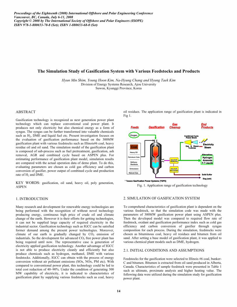
ABSTRACT Gasification technology is recognized as next generation power plant technology which can replace conventional coal power plant It produces not only electricity but also chemical energy as a form of syngas The syngas can be further transformed into valuable chemicals such as H2 DME and liquid fuel etc Present investigation focuses on the evaluation of gasification performance based on the 300MW gasification plant with various feedstocks such as Illinois6 coal heavy residue oil and oil sand The simulation model of the gasification plant is composed of sub-process such as fuel pretreatment gasification ash removal AGR and combined cycle based on ASPEN plus For estimating performance of gasification plant model simulation results are compared with the actual operation data of demo plant To do this evaluating parameters are chosen as cold gas efficiency and carbon conversion of gasifier power output of combined cycle and production rate of H2 and DME KEY WORDS gasification oil sand heavy oil poly generation ASPEN 1 INTRODUCTION Many research and development for renewable energy technologies are being performed with the recognition of without novel technology producing energy continuous high price of crude oil and climate change of the earth However it is their efforts for getting technologies it can not be supplied large capacity of required electricity in the industrial sector Gasification technology such as IGCC can be satisfied former demand among the present power technologies Moreover climate of our earth is gradually changed by CO2 emission of industrials So the development for advanced CO2 free power plant has being required until now The representative case is generation of electricity applied gasification technology Another advantage of IGCC is not able to produce electricity cleanly and efficiently but also produce chemicals such as hydrogen methanol DME with various feedstocks Additionally IGCC can obtain with the process of energy conversion without air pollutant emissions (SOx NOx PM etc) With compared to conventional power plant this technology could be led to total cost reduction of 40~90 Under the condition of generating 300 MW capability of electricity it is indicated to characteristics of gasification plant by supplying various feedstocks such as coal heavy
oil residues The application range of gasification plant is indicated in Fig 1
Steam
HydrogenAmmonia
F-T Liquids
Clean Syngas
End ProductsFeeds
Gas CleanupGasification
Refinery Residues
Heavy Oil
Orimulsion
Coal
Petroleum Coke
Oxygen
Electricity
Solid Sulfur
Slag (ash)
Gas amp SteamTurbines
End ProductsFeeds
Gas Cleanup
Combined CyclePower Block
SULFURRECOVERY
Marketable Byproducts
Alternatives
Alternatives
SULFURREMOVAL
1 Texaco Gasification Power Systems (TGPS)
Natural Gas
Steam
HydrogenAmmonia
F-T Liquids
Clean Syngas
Gasification
Refinery Residues
Heavy Oil
Orimulsion
Coal
Petroleum Coke
Oxygen
Electricity
Solid Sulfur
Slag (ash)
Gas amp SteamTurbines
Combined CyclePower Block
SULFURRECOVERY
Marketable Byproducts
Alternatives
Alternatives
SULFURREMOVAL
1 Texaco Gasification Power Systems (TGPS)
Natural Gas
Fig 1 Application range of gasification technology
2 SIMULATION OF GASIFICATION SYSTEM To comprehend characteristics of gasification plant is dependent on the various feedstock so that the simulation code was made with the parameters of 300MW gasification power plant using ASPEN plus Then the developed model was compared to required flow rate of feedstock oxidant and gasification performance index such as cold gas efficiency and carbon conversion of gasifier through syngas composition for each process During the simulation feedstocks were chosen as bituminous coal heavy oil residues and bitumen from oil sand After setting a base model of gasification plant it was applied to various chemical plant models such as DME hydrogen 21 INITIAL CONDITIONS AND ASSUMPTIONS Feedstocks for the gasification were selected to Illinois 6 coal bunker-C and bitumen Bitumen is extracted from oil sand produced in Alberta Canada Characteristics of sample feedstock were presented in Table 1 such as ultimate proximate analysis and higher heating value The following data were utilized during the simulation study for gasification power plant
Proceedings of the Eighteenth (2008) International Offshore and Polar Engineering ConferenceVancouver BC Canada July 6-11 2008 Copyright copy 2008 by The International Society of Offshore and Polar Engineers (ISOPE)ISBN 978-1-880653-70-8 (Set) ISBN 1-880653-68-0 (Set)
14
ADVANCE y 144 The Simulation Study of Gasification System with Various Feedstocks and Products
Hyun Min Shim Young Hoon Kim Na-Hyung Chang and Hyung Taek Kim
Division of Energy Systems Research Ajou University
Suwon Kyunggi Province South Korea
ABSTRACT
Gasification technology is recognized as next generation power plant technology which can replace conventional coal power plant It produces not only electricity but also chemical energy as a form of syngas The syngas can be further transformed into valuable chemicals such as H2 DME and liquid fuel etc Present investigation focuses on the evaluation of gasification performance based on the 300MW gasification plant with various feedstocks such as Illinois6 coal heavy residue oil and oil sand The simulation model of the gasification plant is composed of sub-process such as fuel pretreatment gasification ash removal AGR and combined cycle based on ASPEN plus For estimating performance of gasification plant model simulation results are compared with the actual operation data of demo plant To do this evaluating parameters are chosen as cold gas efficiency and carbon conversion of gasifier power output of combined cycle and production rate of H2 and DME
KEY WORDS gasification oil sand heavy oil poly generation ASPEN
1 INTRODUCTION
Many research and development for renewable energy technologies are being performed with the recognition of without novel technology producing energy continuous high price of crude oil and climate change of the earth However it is their efforts for getting technologies it can not be supplied large capacity of required electricity in the industrial sector Gasification technology such as IGCC can be satisfied former demand among the present power technologies Moreover climate of our earth is gradually changed by CO2 emission of industrials So the development for advanced CO2 free power plant has being required until now The representative case is generation of electricity applied gasification technology Another advantage of IGCC is not able to produce electricity cleanly and efficiently but also produce chemicals such as hydrogen methanol DME with various feedstocks Additionally IGCC can obtain with the process of energy conversion without air pollutant emissions (SOx NOx PM etc) With compared to conventional power plant this technology could be led to total cost reduction of 40~90 Under the condition of generating 300 MW capability of electricity it is indicated to characteristics of gasification plant by supplying various feedstocks such as coal heavy oil residues The application range of gasification plant is indicated in Fig 1
Steam
Hydrogen
Ammonia
F-T Liquids
Clean Syngas
End
Products
Feeds
Gas
Cleanup
Refinery
Residues
Heavy Oil
Orimulsion
Coal
Petroleum Coke
Oxygen
Electricity
Solid Sulfur
Slag (ash)
Gas amp Steam
Turbines
Gasification
Combined Cycle
Power Block
SULFUR
RECOVERY
Marketable
Byproducts
Alternatives
Alternatives
SULFUR
REMOVAL
1
Texaco Gasification Power Systems (TGPS)
Natural Gas
Fig 1 Application range of gasification technology
2 SIMULATION OF GASIFICATION SYSTEM
To comprehend characteristics of gasification plant is dependent on the various feedstock so that the simulation code was made with the parameters of 300MW gasification power plant using ASPEN plus Then the developed model was compared to required flow rate of feedstock oxidant and gasification performance index such as cold gas efficiency and carbon conversion of gasifier through syngas composition for each process During the simulation feedstocks were chosen as bituminous coal heavy oil residues and bitumen from oil sand After setting a base model of gasification plant it was applied to various chemical plant models such as DME hydrogen
21 INITIAL CONDITIONS AND ASSUMPTIONS
Feedstocks for the gasification were selected to Illinois 6 coal bunker-C and bitumen Bitumen is extracted from oil sand produced in Alberta Canada Characteristics of sample feedstock were presented in Table 1 such as ultimate proximate analysis and higher heating value The following data were utilized during the simulation study for gasification power plant
Table 1 Ultimate and proximate analysis of feedstock
The IGCC power plant modeled in this study is limited to gasification of dry coal feeding type For the 300 MW electricity power flow rates of fuels and utilities are calculated and considered at gasification power plant model The supplying conditions of each fuel and utilities are presented in Table 2
Table 2 Supplying conditions of each feedstock
22 MODELING OF UNIT PROCESS
After simulated gasification power plant for each case the results are gained and evaluated by comparison of reference data The gasification plant is representatively composed of preparing fuel gasification ash removal acid gas removal and combined cycle with gas turbine and steam turbine For considering each gasification plant dependent on feedstock the preparing fuel process is only changed and others are applied at the same Preparing fuel process is composed of coal pulverizing drying and transporting system with nitrogen gas in the section of coal gasification After being pulverized by average particle size of 74 those coals are dried at 95 of nitrogen gas and transported to gasifier with mixing The case of heavy residue oil is composed of fuel mixing and supplying system appropriated at liquid phase It is assumed that gasifier is identically operated at 28 kgcm2 1420 in this model However gasification mechanism complexes with various reactions those are simplified to limit 11 major equations in this model The section of gasification process is composed of decomposition gasification and soot (slag) generation its process flow is shown in Fig2 Those reaction equations are summarized in Eqs1 through 11
2
05
COCO
+reg
(1)
2
2
CCOCO
+reg
(2)
22
CHOCOH
+reg+
(3)
24
2
CHCH
+reg
(4)
22
05
COOCO
+reg
(5)
222
COHOCOH
+reg+
(6)
422
3
CHHOCOH
+reg+
(7)
222
05
HOHO
+reg
(8)
22
HSHS
+reg
(9)
223
32
NHNH
+reg
(10)
222
COSHOCOHS
+reg+
(11)
The model of gasification process is made by Aspen Plus indicated in Fig2
Fuels
(coal heavy residue bitumen)
Gasifiermodel
Decomposition process
Oxygen 95
Gasification process
Heat
Raw syngas
Slag
Fuels
(coal heavy residue bitumen)
Gasifiermodel
Decomposition process
Oxygen 95
Gasification process
Heat
Raw syngas
Slag
Fig 2 Simulation model for gasification process
The gasification model is made of thermal decomposition process which changed volatile matter from solid particle and gasification process which proceeded to partial combustion of carbon particle and organic materials With passing through the cyclone and metal filter by turns fly-ash on the inside syngas is removed to near the 99 of removal efficiency Then syngas removed ash lead to acid gas removal (AGR) process which can be captured CO2 H2S gas by absorbent of MEA solution the syngas is washed without acid gases
3 SIMULATION OF APPLICATION SYSTEM
The gasification technology can variously convert primary resources to secondary energy such as DME H2 and electricity For simulating each system common processes are basically set from fuel preparing to AGR process Then the rest processes which are required in application system are appropriately added The capacity of syngas used to application system is assumed to equal syngas flow rate of power plant produced to 300 MW
31 MODELING OF DME PROCESS
The simulation model of DME process was based on the design and operating parameters of pilot scale plant located in Institute for Advanced Engineering (IAE) Korea The model developed with ASPEN plus is illustrated in Fig 3 It should be focused that fixed bed type reactor was chosen to simulate the characteristics of DME reactor during the study The formation of the model is composed with various types of unit blocks syngas compressor as compress 4 stages and operated to maximum 90 kgcm2 PCV as valve controlling pressure preheater as raising to 220 of syngas temperature DME reactor as fixed bed reactor with shell amp tube heat exchanger which being operated to the range of 240~310 50~70 kgcm2 steam drum as controlling reactor temperature with generating steam Heat exchanger as cooling product gas after DME reactor Sep-1 as separating methanol in the product Sep-2 as separating high purity of DME in the product
The syngas from the gasification is mainly composed of CO and H2 Overall DME synthesis process can include 3 steps such as methanol synthesis dehydration and WGS (water gas shift) reaction as described in Eqs (12) through (17) The formation of methanol was considered by two reaction mechanisms as illustrated in both Eq12 and Eq13 Eq12 is formation of methanol participating CO and H2 as major reactants and this reaction emits high reaction enthalpy While Eq13 is led by participating CO2 and H2 it has less reaction enthalpy than Eq12 It is assumed that both reactions can be proceeded to produce methanol simultaneously in this study
23
2
COHCHOH
+laquo
- 434 kcalmol-DME (12)
2232
3
COHCHOHHO
+laquo+
- 135 kcalmol-DME (13)
Methanol experienced following reaction of dehydration with DME synthesis catalyst as in Eq14 DME catalyst used during the synthesis is assumed as CuZnOAl2O3+γ-Al2O3 in this process Eq15 is shown as WGS reaction It has a role to supply CO2 and H2 for DME synthesis
3332
2
CHOHCHOCHHO
laquo+
- 56 kcalmol-DME (14)
222
COHOCOH
+laquo+
- 98 kcalmol-DME (15)
By integrating Eqs(12) through (15) two different cases of DME overall reaction are respectively obtained such as Eq16 and Eq17 The case of Eq16 is combined into Eq12 Eq14 and Eq15 And if WGS reaction slowly proceeded DME overall reaction is led to Eq17
2332
33
COHCHOCHCO
+laquo+
- 588 kcalmol-DME (16)
2332
24
COHCHOCHHO
+laquo+
- 490 kcalmol-DME (17)
Syngascomp
Syngas
PCV
Preheater
DME reactor
Steam heater
Supply pump
Steam drum
DME
SEP-1
SEP-2
Heat exchanger
Syngascomp
Syngas
PCV
Preheater
DME reactor
Steam heater
Supply pump
Steam drum
DME
SEP-1
SEP-2
Heat exchanger
Fig 3 Simulation model of direct DME (catalyst) process
32 MODELING OF HYDROGEN PROCESS
The model of hydrogen manufacturing process is composed of high and low temperature shift reactor which respectively operated at 450 220 AGR and PSA (pressure swing adsorption) for obtaining high purity of hydrogen After passing through heat exchanger which can recovery waste heat for generating steam from high temperature of syngas dividing two streams between HT and LT shift reactor with adding steam Passing through HT and LT shift reactor most CO component of syngas is converted to H2 Then 99 of acid gases (CO2 H2S) among the converted syngas are removed by 20 wt MEA solutions The washed syngas composed of H2 component is compressed and 999 of H2 is separated by PSA This model is illustrated in Fig 4
Heat Exchanger
City Water
High Temp
Shift Reactor
Low Temp
Shift Reactor
Syngasfrom gasifier
Absorber
Heat Exchanger
Regenerator
MEA solution
High Purity CO
2
Hydrogen PSA
High Purity H
2
gas
CompressorHeat Exchanger
City Water
High Temp
Shift Reactor
Low Temp
Shift Reactor
Syngasfrom gasifier
Absorber
Heat Exchanger
Regenerator
MEA solution
High Purity CO
2
Hydrogen PSA
High Purity H
2
gas
Compressor
Fig 4 Simulation model of H2 manufacturing process
33 MODELING OF COMBINED CYCLE
The washed syngas is compressed at 15~16 kgcm2 the compressed syngas is injected to gas turbine combustor with high pressure of air and N2 gas After being combusted near 1260 at the gas turbine cycle it is generated electricity by high thermal and pressurized combustion gas At last exhaust gas including high thermal pass through heat recovery steam generator (HRSG) waste heat of exhaust gas is recovered and used as heat source at the steam turbine cycle Steam turbine composed of 3 stage compressors operated in LP (4 kgcm2) IP (20 kgcm2) and HP (98 kgcm2) steam It is important to supply air as oxidant and N2 as diluents gas into combustor of gas turbine in this process So the amount of both air and N2 isnrsquot only related to power but also temperature of combustor at the gas turbine Therefore input of gas turbine is determined to exhaust 7~9 of CO2 concentration among the burned gas quantities of air and N2 gas set to following Table 3
Table 3 Supplying condition of gas turbine cycle for each case
34 SIMULATION PROCEDURE
After setting each process model various fuels are applied to these models Considering fuels and products in the gasification model there are 9 cases such as Fig 5
Illinois6 coal
Bunker-C
Bitumen
Gasification
DME
Hydrogen
Electricity
Illinois6 coal
Bunker-C
Bitumen
Gasification
DME
Hydrogen
Electricity
Fig 5 Cases of gasification plant with various fuels and products
For comparing production of each case heating value of feedstock become equivalent to control quantities of fuels oxygen and steam like as Table 2 The O2fuel ratio was respectively set to 086 as Illinois 6 coal 113 as bunker-C and bitumen After integrated between gasification considering various fuels and products model such as DME hydrogen and electricity mediated streams like materials heat and work for integrated each system
4 SIMULATION RESULTS
It is considered that what is differs from gasification characteristics of each fuel For indicating its gasification characteristics it is suggested parameters can indicate gasification performance such as syngas composition cold gas efficiency ( CGE) and carbon conversion ( CC) The CGE and CC are respectively defined as Eq18 and Eq19
[kcal]
()100
[kcal]
HHVinproductgas
CGE
HHVinfeedstock
=acute
(18)
[kmolh]
()100
[kmolh]
carboninproductgas
CC
carboninfeedstock
=acute
(19)
Table 4 Syngas composition of each fuel at the latter part of gasifier
It is shown that syngas composition of each fuel produced at the latter part of gasifier by Table 4 According to the results of syngas composition H2CO ratio of Illinois6 coal(IC) is about 0465 bunker-C (BC) and bitumen (BT) are similarly shown as 122
758
917
976
940
953
995
0465
1231
1223
0
20
40
60
80
100
ICBCBT
CGECC()
00
02
04
06
08
10
12
14
H2CO ratio
CGE
CC
H2CO
Fig 6 H2CO ratio cold gas efficiency and carbon conversion by gasification of each fuel
In the face of gasification performance shown at Fig6 as CGE and CC for each fuel CGE and CC of Illinois6 coal are respectively calculated on 758 and 940 Illinois6 coal has lowest CGE that reason is that heat value of combustible syngas (CO H2 and CH4) is the lowest among the 3 type of fuel
Table 5 Production rate of each product by various fuels
It is obtained production rate of 9 cases by various feedstock through individual model as Table5 These results are just indicated total quantities of final products For comparing with each case equivalently it is approached energy conversion ratio (caloric of productcaloric of input materials) in the view of the thermodynamic 1st law Before calculating energy conversion ratio of the each case it is firstly performed to determine control volume in the individual model Then caloric of final products (electricity DME H2) obtained by simulation is divided by caloric of input materials (fuel O2 air required electricity etc) reflected in each model Through the procedure of converting equivalent caloric it is obtained followed energy conversion ratio of various products with feedstock as Fig7
IC
BC
BT
Electricity
DME
H2
0683
08310883
0321
0714
0724
0373
031
0313
0
02
04
06
08
1
Energy conversion ratio
Feedstock
Products
Electricity
DME
H2
Fig 7 Energy conversion ratio of various feedstocks and products
However cold gas efficiency of Illinois6 coal is the lowest among the fuels utilization of coal is relatively prior to the other feedstock as 0373 of energy conversion ratio in the face of electricity generation As comparing with energy conversion ratio in this case it has to consider controlling concentration of exhaust gas (CO2 O2 NOx etc) in the gas turbine cycle So the quantities of air and diluents N2 injected to combustor are different Illinois6 coal from liquid oil such as bunker-C bitumen These parameters are effected generating power Coal is shown into the lowest energy conversion ratio as 0321 in the face of DME production That reason is syngas derived from pulverized coal has lower H2 portion than liquid oil such as bunker-C and bitumen It is important that H2CO ratio approach near the 10 in the DME process In the face of hydrogen production bitumen has competitive among the feedstock H2 production is proportional to hydrogen content of syngas before shift reaction
5 SUMMARY
Through the simulation study for gasification system applied to various feedstocks and products base models of both gasification and application system were constructed by ASPEN plus After being integrated each unit model composed gasification system overall systems such as power DME and H2 manufacturing plant were simulated with changing feedstocks as Illinois6 coal bunker-C and bitumen Then it was evaluated gasification performance used by cold gas efficiency carbon conversion and H2CO ratio for each case In case of gasification with Illinois6 coal there were shown 0465 of H2CO ratio 758 of cold gas efficiency and 940 of carbon conversion The gasification models applied bunker-C and bitumen were respectively shown 1231 1223 of H2CO ratio 917 976 of cold gas efficiency and 953 995 of carbon conversion For comparing with gasification systems had different feedstock and products caloric values of the both input and output materials were calculated and become equivalent used energy conversion ratio in the view of thermodynamic 1st laws
ACKNOWLEDGEMENTS
The research is outcome of the fostering project of the ldquoBest Labrdquo in the area of IGCC supported financially by the Ministry of Commerce Industry and Energy (MOCIE)
REFERENCES
Christopher Higman Maarten van der Burgt (2003) Gasification Gulf Professional Publishing pp 25-26 133 316-317
Process Engineering Division (2000) Texaco Gasifier IGCC Base Cases NETL DOE Report PED-IGCC-98-001
Process Engineering Division (2000) Shell Gasifier IGCC Base Cases NETL DOE Report PED-IGCC-98-002
Sun Q Liu CW Pan W Zhu QM and Deng JF (1998) Applied Catalysis A Vol 171 No 2 pp 301
Williams A Pourkashanian M Jones JM Skorupska N (1999) Combustion and Gasification of Coal Taylor amp Francis Inc pp 86-88
Yotaro Ohno Mamoru Omiya (2003) 12th ICCS- Coal Conversion into DME (wwwjfe-holdingscojpdmepdfronbun07pdf)
13
13
13
13
13
13
13
13
13
13
13
13
13
13
13
13
13
13
13
13
13
13
13
13
13
13
13
13
13
13
13
13
13
13
13