The shaft running surface (Kalsi Seals Handbook, … shaft running surface Chapter D2 Page 2 Contact...
13
Revision 4 March 22, 2018 Individual chapters of the Kalsi Seals Handbook are periodically updated. To determine if a newer revision of this chapter exists, please visit www.kalsi.com/seal-handbook.htm. NOTICE: The information in this chapter is provided under the terms and conditions of the Offer of Sale, Disclaimer, and other notices provided in the front matter of this handbook. Document 3073 © 2018 Kalsi Engineering, Inc. All rights reserved. Kalsi Seals Handbook Chapter D2 The shaft running surface
Transcript of The shaft running surface (Kalsi Seals Handbook, … shaft running surface Chapter D2 Page 2 Contact...
Revision 4 March 22, 2018
Individual chapters of the Kalsi Seals Handbook are periodically updated. To determine if
a newer revision of this chapter exists, please visit www.kalsi.com/seal-handbook.htm.
NOTICE: The information in this chapter is provided under the terms and conditions of the Offer of
Sale, Disclaimer, and other notices provided in the front matter of this handbook.
Document 3073 © 2018 Kalsi Engineering, Inc. All rights reserved.
Kalsi Seals Handbook
Chapter D2
The shaft running surface
The shaft running surface Chapter D2 Page 1
Search this handbook Contact Kalsi Engineering
1. Diameter of the shaft sealing surface
For the best abrasion resistance, size the sealing surface of the shaft to match the
approximate as-molded seal inside diameter (see the website, or call Kalsi Engineering).
If the shaft is significantly smaller than the inside diameter of the seal, the resulting
increased circumferential seal compression may promote skew-induced wear.1 If the shaft
is significantly larger than the inside diameter of the seal, circumferential tension may
cause cross sectional twisting or other problems, such as reduced compression or
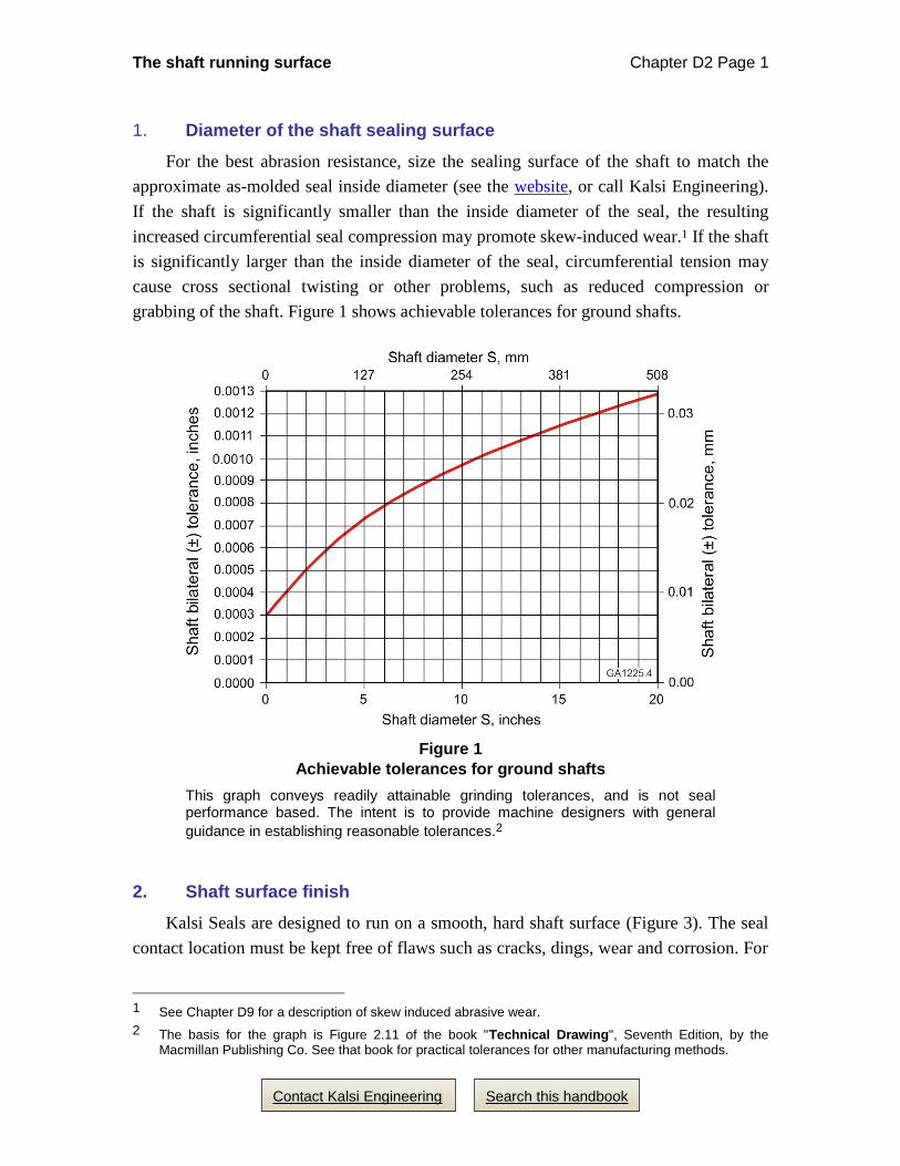
grabbing of the shaft. Figure 1 shows achievable tolerances for ground shafts.
Figure 1
Achievable tolerances for ground shafts
This graph conveys readily attainable grinding tolerances, and is not seal performance based. The intent is to provide machine designers with general
guidance in establishing reasonable tolerances.2
2. Shaft surface finish
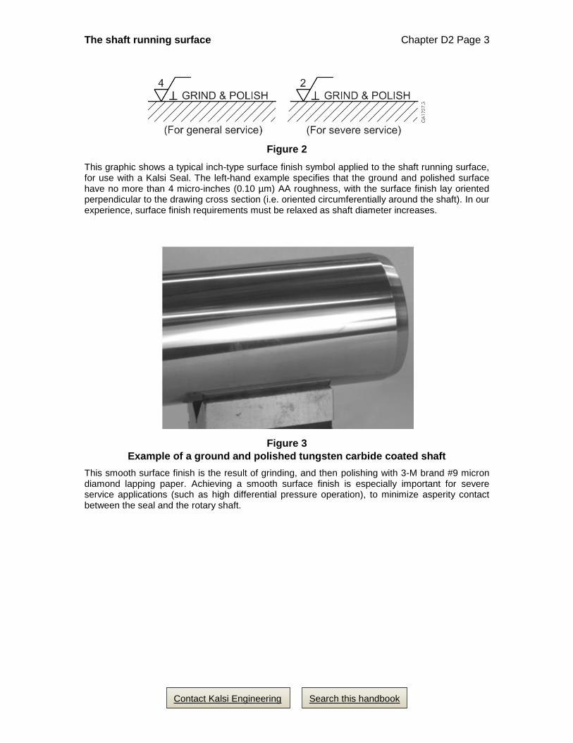
Kalsi Seals are designed to run on a smooth, hard shaft surface (Figure 3). The seal
contact location must be kept free of flaws such as cracks, dings, wear and corrosion. For
1 See Chapter D9 for a description of skew induced abrasive wear.
2 The basis for the graph is Figure 2.11 of the book "Technical Drawing", Seventh Edition, by the Macmillan Publishing Co. See that book for practical tolerances for other manufacturing methods.
The shaft running surface Chapter D2 Page 2
Search this handbook Contact Kalsi Engineering
best results on small diameter shafts, use a ground and polished surface finish of 4 µin
(0.10 µm) AA3 or less for general purpose use, and 2 µin (0.05 µm) AA or less for severe
service use.4 Examples of severe service include high differential pressure, high
temperature applications, or applications that use low viscosity5 lubricants. Even glass
smooth is acceptable, because Kalsi Seal rotary performance is not dependent on
retention of oil by the shaft surface finish. During initial development, Kalsi Seals were
actually tested on a glass surface, in order to observe and measure film thickness. As
shaft diameter increases, it becomes less practical to achieve a 2 to 4 micro-inch AA
finish.
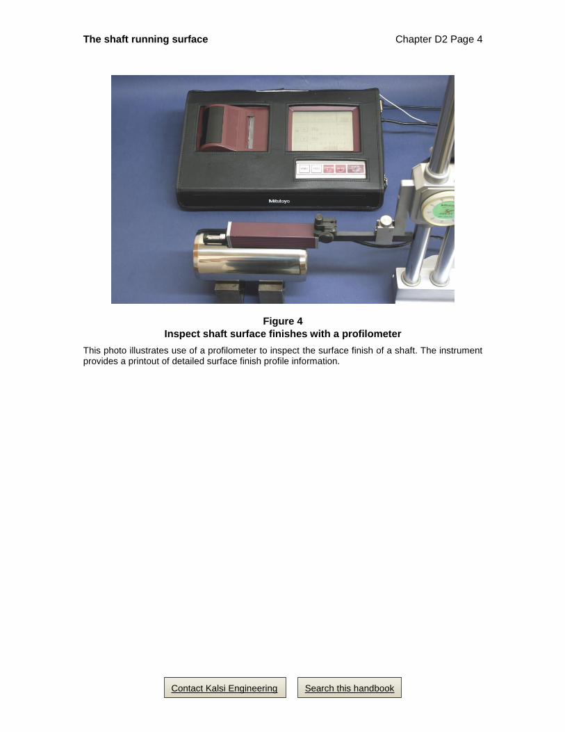
For best results, use an electronic profilometer (Figure 4) to inspect the surface finish
on all new and refinished shafts. If a profilometer is unavailable, surface finish can be
estimated using a surface finish comparison standard (Figure 5).6
Since surface texture is dependent on manufacturing process, shaft drawings should
designate “fine grinding” or “diamond grinding” in addition to the usual surface finish
symbol (Figure 2). Avoid vendors who achieve the designated surface finish by filling in
the porosity of the tungsten carbide coating with a plastic coating.
The surface finish lay should be perpendicular to the shaft axis, rather than spiral, if
possible. Spiral lead can potentially pump fluid past the rotary seal. If spiral lead is
unavoidable, then orient it to pump lubricant past the seal, and to oppose environmental
invasion.
3 The surface finish roughness arithmetic average (AA) is also known as roughness average (Ra). The 4
micro-inch AA recommendation is the result of solving a seal performance issue by switching from an 8 to a 4 micro-inch AA finish. The larger the allowed average roughness value, the easier it is for the average to mask a sizable defect.
4 We reviewed the surface finish measurements from 35 2.75” (69.85mm) diameter test sleeves from our rotary seal test fixtures, and found that the average Ra for all the sleeves was 2 micro-inches, with a range of 1.3 to 3.3 micro-inches Ra. The average Rz for all 35 sleeves was 27 micro-inches, with a range of 16.1 to 49.2 micro-inches Rz.
5 Viscosity is a measure of resistance to flow. Low viscosity lubricants are thinner, and less resistant to flow. High viscosity lubricants are thicker, and more resistant to flow.
6 A person can typically detect a surface finish of 16 micro-inches and above by dragging their fingernail across the lay of the surface.
The shaft running surface Chapter D2 Page 3
Search this handbook Contact Kalsi Engineering
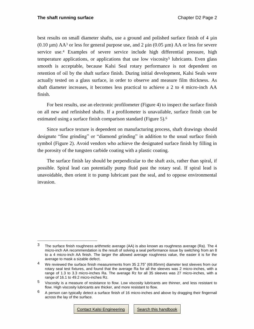
Figure 2
This graphic shows a typical inch-type surface finish symbol applied to the shaft running surface, for use with a Kalsi Seal. The left-hand example specifies that the ground and polished surface have no more than 4 micro-inches (0.10 µm) AA roughness, with the surface finish lay oriented perpendicular to the drawing cross section (i.e. oriented circumferentially around the shaft). In our experience, surface finish requirements must be relaxed as shaft diameter increases.
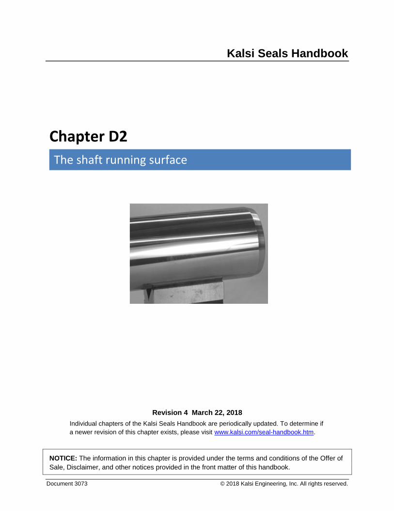
Figure 3
Example of a ground and polished tungsten carbide coated shaft
This smooth surface finish is the result of grinding, and then polishing with 3-M brand #9 micron diamond lapping paper. Achieving a smooth surface finish is especially important for severe service applications (such as high differential pressure operation), to minimize asperity contact between the seal and the rotary shaft.
The shaft running surface Chapter D2 Page 4
Search this handbook Contact Kalsi Engineering
Figure 4
Inspect shaft surface finishes with a profilometer
This photo illustrates use of a profilometer to inspect the surface finish of a shaft. The instrument provides a printout of detailed surface finish profile information.

The shaft running surface Chapter D2 Page 5
Search this handbook Contact Kalsi Engineering
Figure 5
Surface finish comparison standard
In the absence of an electronic profilometer, a surface finish comparison standard can be used to estimate surface finish.
The shaft running surface Chapter D2 Page 6
Search this handbook Contact Kalsi Engineering
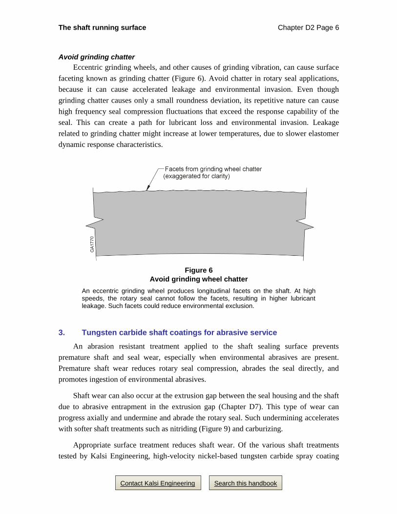
Avoid grinding chatter
Eccentric grinding wheels, and other causes of grinding vibration, can cause surface
faceting known as grinding chatter (Figure 6). Avoid chatter in rotary seal applications,
because it can cause accelerated leakage and environmental invasion. Even though
grinding chatter causes only a small roundness deviation, its repetitive nature can cause
high frequency seal compression fluctuations that exceed the response capability of the
seal. This can create a path for lubricant loss and environmental invasion. Leakage
related to grinding chatter might increase at lower temperatures, due to slower elastomer
dynamic response characteristics.
Figure 6
Avoid grinding wheel chatter
An eccentric grinding wheel produces longitudinal facets on the shaft. At high speeds, the rotary seal cannot follow the facets, resulting in higher lubricant leakage. Such facets could reduce environmental exclusion.
3. Tungsten carbide shaft coatings for abrasive service
An abrasion resistant treatment applied to the shaft sealing surface prevents
premature shaft and seal wear, especially when environmental abrasives are present.
Premature shaft wear reduces rotary seal compression, abrades the seal directly, and
promotes ingestion of environmental abrasives.
Shaft wear can also occur at the extrusion gap between the seal housing and the shaft
due to abrasive entrapment in the extrusion gap (Chapter D7). This type of wear can
progress axially and undermine and abrade the rotary seal. Such undermining accelerates
with softer shaft treatments such as nitriding (Figure 9) and carburizing.
Appropriate surface treatment reduces shaft wear. Of the various shaft treatments
tested by Kalsi Engineering, high-velocity nickel-based tungsten carbide spray coating
The shaft running surface Chapter D2 Page 7
Search this handbook Contact Kalsi Engineering
provides the best wear resistance by far, and is our preference for both abrasive and
nonabrasive applications.
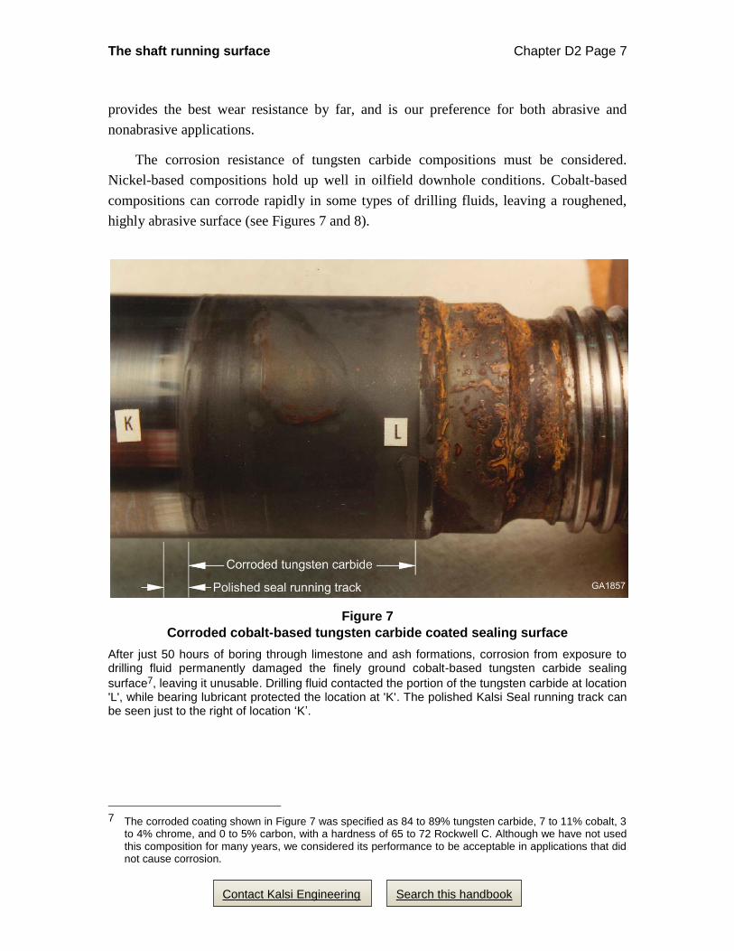
The corrosion resistance of tungsten carbide compositions must be considered.
Nickel-based compositions hold up well in oilfield downhole conditions. Cobalt-based
compositions can corrode rapidly in some types of drilling fluids, leaving a roughened,
highly abrasive surface (see Figures 7 and 8).
Figure 7
Corroded cobalt-based tungsten carbide coated sealing surface
After just 50 hours of boring through limestone and ash formations, corrosion from exposure to drilling fluid permanently damaged the finely ground cobalt-based tungsten carbide sealing
surface7, leaving it unusable. Drilling fluid contacted the portion of the tungsten carbide at location 'L', while bearing lubricant protected the location at 'K'. The polished Kalsi Seal running track can be seen just to the right of location ‘K’.
7 The corroded coating shown in Figure 7 was specified as 84 to 89% tungsten carbide, 7 to 11% cobalt, 3
to 4% chrome, and 0 to 5% carbon, with a hardness of 65 to 72 Rockwell C. Although we have not used this composition for many years, we considered its performance to be acceptable in applications that did not cause corrosion.
The shaft running surface Chapter D2 Page 8
Search this handbook Contact Kalsi Engineering
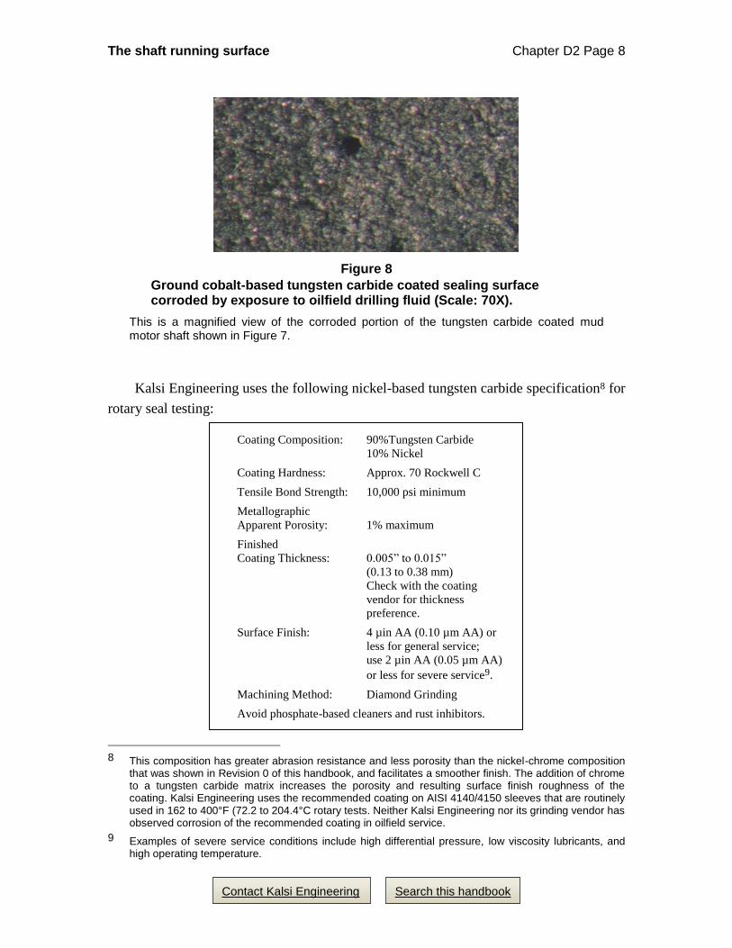
Figure 8
Ground cobalt-based tungsten carbide coated sealing surface corroded by exposure to oilfield drilling fluid (Scale: 70X).
This is a magnified view of the corroded portion of the tungsten carbide coated mud motor shaft shown in Figure 7.
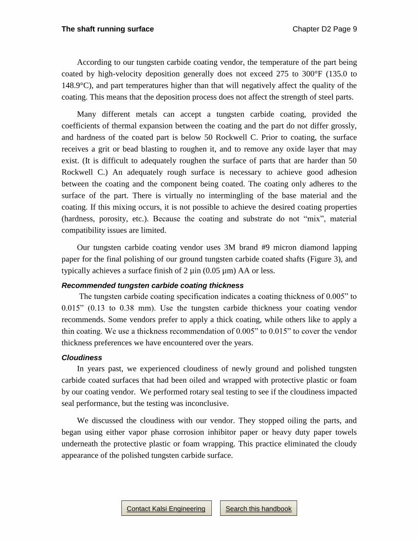
Kalsi Engineering uses the following nickel-based tungsten carbide specification8 for
rotary seal testing:
Coating Composition: 90%Tungsten Carbide
10% Nickel
Coating Hardness: Approx. 70 Rockwell C
Tensile Bond Strength: 10,000 psi minimum
Metallographic
Apparent Porosity: 1% maximum
Finished
Coating Thickness: 0.005” to 0.015”
(0.13 to 0.38 mm)
Check with the coating
vendor for thickness
preference.
Surface Finish: 4 µin AA (0.10 µm AA) or
less for general service;
use 2 µin AA (0.05 µm AA)
or less for severe service9.
Machining Method: Diamond Grinding
Avoid phosphate-based cleaners and rust inhibitors.
8 This composition has greater abrasion resistance and less porosity than the nickel-chrome composition
that was shown in Revision 0 of this handbook, and facilitates a smoother finish. The addition of chrome to a tungsten carbide matrix increases the porosity and resulting surface finish roughness of the coating. Kalsi Engineering uses the recommended coating on AISI 4140/4150 sleeves that are routinely used in 162 to 400°F (72.2 to 204.4°C rotary tests. Neither Kalsi Engineering nor its grinding vendor has observed corrosion of the recommended coating in oilfield service.
9 Examples of severe service conditions include high differential pressure, low viscosity lubricants, and high operating temperature.
The shaft running surface Chapter D2 Page 9
Search this handbook Contact Kalsi Engineering
According to our tungsten carbide coating vendor, the temperature of the part being
coated by high-velocity deposition generally does not exceed 275 to 300°F (135.0 to
148.9°C), and part temperatures higher than that will negatively affect the quality of the
coating. This means that the deposition process does not affect the strength of steel parts.
Many different metals can accept a tungsten carbide coating, provided the
coefficients of thermal expansion between the coating and the part do not differ grossly,
and hardness of the coated part is below 50 Rockwell C. Prior to coating, the surface
receives a grit or bead blasting to roughen it, and to remove any oxide layer that may
exist. (It is difficult to adequately roughen the surface of parts that are harder than 50
Rockwell C.) An adequately rough surface is necessary to achieve good adhesion
between the coating and the component being coated. The coating only adheres to the
surface of the part. There is virtually no intermingling of the base material and the
coating. If this mixing occurs, it is not possible to achieve the desired coating properties
(hardness, porosity, etc.). Because the coating and substrate do not “mix”, material
compatibility issues are limited.
Our tungsten carbide coating vendor uses 3M brand #9 micron diamond lapping
paper for the final polishing of our ground tungsten carbide coated shafts (Figure 3), and
typically achieves a surface finish of 2 µin (0.05 µm) AA or less.
Recommended tungsten carbide coating thickness
The tungsten carbide coating specification indicates a coating thickness of 0.005” to
0.015” (0.13 to 0.38 mm). Use the tungsten carbide thickness your coating vendor
recommends. Some vendors prefer to apply a thick coating, while others like to apply a
thin coating. We use a thickness recommendation of 0.005” to 0.015” to cover the vendor
thickness preferences we have encountered over the years.
Cloudiness
In years past, we experienced cloudiness of newly ground and polished tungsten
carbide coated surfaces that had been oiled and wrapped with protective plastic or foam
by our coating vendor. We performed rotary seal testing to see if the cloudiness impacted
seal performance, but the testing was inconclusive.
We discussed the cloudiness with our vendor. They stopped oiling the parts, and
began using either vapor phase corrosion inhibitor paper or heavy duty paper towels
underneath the protective plastic or foam wrapping. This practice eliminated the cloudy
appearance of the polished tungsten carbide surface.
The shaft running surface Chapter D2 Page 10
Search this handbook Contact Kalsi Engineering
You should also make sure you and your vendors avoid cleaning solutions that
deposit solids on the shaft, such as phosphate based cleaner/rust inhibitors. Phosphate
based cleaners are known to cause significantly higher seal running torque and
accelerated seal wear. Anyone who assembles and disassembles tools that use Kalsi
Seals should read Chapter D19 of the handbook. Item 4 on Page 4 in Chapter D19
discusses the cleaning of parts. We use a water soluble cleaning solution (see
attachment) and/or Isopropyl alcohol to clean the parts for our lab testing.
Addressing worn tungsten carbide surfaces
The sealing surface of the shaft is a key part of sealing functionality. A rough, worn
surface encourages seal slippage, adhesive wear, and third body wear, and increases seal
generated heat. Maintenance of the shaft surface is an important part of equipment
maintenance, and original equipment manufacturers should establish a maintenance
process that allows worn shafts to be refurbished.
Shafts with worn sealing surfaces eventually need to be stripped, reground, and
polished. When the surface finish of a tungsten carbide coated shaft initially begins to
degrade,10 honing and polishing typically can eliminate the wear track11 and restore the
recommended surface finish. The honing process involves the removal of a few ten-
thousandths of an inch of material, allowing the part to remain within tolerance. Even
without honing, polishing with diamond-coated abrasive cloth can sometimes help restore
roughened surfaces to the recommended finish. With either method, it is not necessary to
replace the tungsten carbide during every rebuild.
With the larger cross-section seals that are typically used in many applications,
honing the shaft down by even as much as 0.002 or 0.003” has very little practical effect
on seal compression.
4. Shaft coatings for nonabrasive service
We prefer ground and polished tungsten carbide
We prefer ground and polished nickel-based tungsten carbide coating from a
performance standpoint, even for nonabrasive service. Nevertheless, some customers may 10 At what surface roughness arithmetic average should the sealing surface of a shaft be reprocessed?
Surface finish is a complex attribute to measure and describe, and surface roughness arithmetic average is far from being a comprehensive measurement. Still, to state a number as a general guideline, we recommend refinishing if the running track of the seal exceeds 8 micro-inches, arithmetic average.
11 We do not provide a recommended allowance for wear track depth, because of the potential but unknown effects of the overall profile of the wear track, and the general lack of information on all the possible implications of running on a wear track of measureable depth. Instead, we recommend honing, to eliminate the wear track altogether.
The shaft running surface Chapter D2 Page 11
Search this handbook Contact Kalsi Engineering
wish to evaluate less expensive coatings for cost sensitive, nonabrasive service
applications.
Nitriding
Suitably finished nitrided surfaces and carburized surfaces, can be useful in
nonabrasive environments, but will groove in abrasive environments, potentially
undermining the rotary seal (Figure 9). Avoid chromium oxide coatings, which have a
microstructure that can be extremely damaging to the Kalsi Seals.
Ground hard chrome
Ground hard chrome may have utility in nonabrasive applications; however, some
hard-chromed surfaces can produce increased torque. Achieving adhesion between the
chrome and the base metal can be difficult if silicone-based cutting fluids are used during
lathe turning operations prior to plating. Silicone is difficult to remove, and some chrome
plating vendors routinely sand blast before plating as a precaution.
Hardide
Hardide12 has been tested with -10 and -11 seal materials, and has demonstrated
utility in nonabrasive applications. The -10 tests were with an ISO 32 viscosity grade
lubricant at 15 psi (103.4 kPa), at 162 to 300°F (72.2 to 148.9°C). The -11 seals were
tested with an ISO 320 viscosity grade lubricant at 15 to 1,500 psi (103.4 kPa to 10.34
MPa), at 162°F (72.2°C). Torque values and hydrodynamic pumping related leak rates
were within the range typical of seals running on surfaces coated with nickel-based
tungsten carbide. Sleeve surface finishes ranged from 2 to 7 micro-inches RA (0.05 to
0.18 µm). The testing indicates a correlation between smoother surface finishes and
lower running torque.
12 Hardide is the trademarked name of a proprietary coating of Hardide Plc, (Bicester, Oxfordshire, United
Kingdom, and Houston, Texas).
The shaft running surface Chapter D2 Page 12
Search this handbook Contact Kalsi Engineering
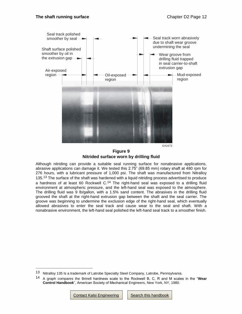
Figure 9
Nitrided surface worn by drilling fluid
Although nitriding can provide a suitable seal running surface for nonabrasive applications, abrasive applications can damage it. We tested this 2.75” (69.85 mm) rotary shaft at 480 rpm for 276 hours, with a lubricant pressure of 1,000 psi. The shaft was manufactured from Nitralloy
135.13 The surface of the shaft was hardened with a liquid nitriding process advertised to produce
a hardness of at least 60 Rockwell C.14 The right-hand seal was exposed to a drilling fluid environment at atmospheric pressure, and the left-hand seal was exposed to the atmosphere. The drilling fluid was 9 lb/gallon, with a 1.5% sand content. The abrasives in the drilling fluid grooved the shaft at the right-hand extrusion gap between the shaft and the seal carrier. The groove was beginning to undermine the exclusion edge of the right-hand seal, which eventually allowed abrasives to enter the seal track and cause wear to the seal and shaft. With a nonabrasive environment, the left-hand seal polished the left-hand seal track to a smoother finish.
13 Nitralloy 135 Is a trademark of Latrobe Specialty Steel Company, Latrobe, Pennsylvania. 14 A graph compares the Brinell hardness scale to the Rockwell B, C, R and M scales in the “Wear
Control Handbook”, American Society of Mechanical Engineers, New York, NY, 1980.
Seal track worn abrasivelydue to shaft wear grooveundermining the seal
Wear groove from drilling fluid trappedin seal carrier-to-shaftextrusion gap
GA1673
Mud-exposed region
Oil-exposed region
Air-exposed region
Seal track polishedsmoother by seal
Shaft surface polishedsmoother by oil inthe extrusion gap