THE SERIES TRANSAXLE GEARBOX UNITS - Hewland … · THE SERIES TRANSAXLE GEARBOX UNITS These units...
19
Transcript of THE SERIES TRANSAXLE GEARBOX UNITS - Hewland … · THE SERIES TRANSAXLE GEARBOX UNITS These units...
THE SERIES
TRANSAXLE GEARBOX UNITS
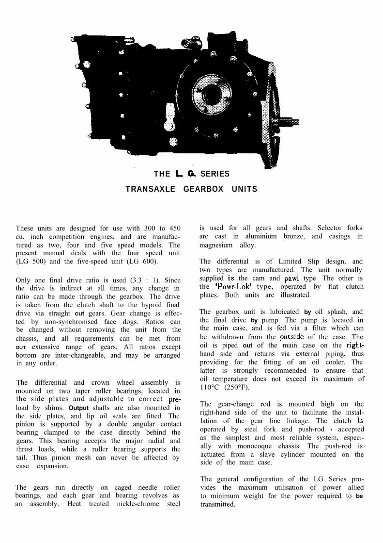
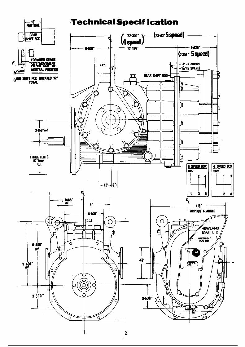
These units are designed for use with 300 to 450cu. inch competition engines, and are manufac-tured as two, four and five speed models. Thepresent manual deals with the four speed unit(LG 500) and the five-speed unit (LG 600).
Only one final drive ratio is used (3.3 : 1). Sincethe drive is indirect at all times, any change inratio can be made through the gearbox. The driveis taken from the clutch shaft to the hypoid finaldrive via straight cut gears. Gear change is effec-ted by non-synchronised face dogs. Ratios canbe changed without removing the unit from thechassis, and all requirements can be met fromOUT extensive range of gears. All ratios exceptbottom are inter-changeable, and may be arrangedin any order.
The differential and crown wheel assembly ismounted on two taper roller bearings, located inthe side plates and adjustable to correct load by shims. Output shafts are also mounted inthe side plates, and lip oil seals are fitted. Thepinion is supported by a double angular contactbearing clamped to the case directly behind thegears. This bearing accepts the major radial andthrust loads, while a roller bearing supports thetail. Thus pinion mesh can never be affected bycase expansion.
The gears run directly on caged needle rollerbearings, and each gear and bearing revolves asan assembly. Heat treated nickle-chrome steel
is used for all gears and shafts. Selector forksare cast in aluminium bronze, and casings inmagnesium alloy.
The differential is of Limited Slip design, andtwo types are manufactured. The unit normallysupplied the cam and type. The other isthe type, operated by flat clutchplates. Both units are illustrated.
The gearbox unit is lubricated by oil splash, andthe final drive by pump. The pump is located inthe main case, and is fed via a filter which canbe withdrawn from the of the case. Theoil is piped out of the main case on the hand side and returns via external piping, thusproviding for the fitting of an oil cooler. Thelatter is strongly recommended to ensure thatoil temperature does not exceed its maximum of110°C (250°F).
The gear-change rod is mounted high on theright-hand side of the unit to facilitate the instal-lation of the gear line linkage. The clutch operated by steel fork and push-rod acceptedas the simplest and most reliable system, especi-ally with monocoque chassis. The push-rod isactuated from a slave cylinder mounted on theside of the main case.
The general configuration of the LG Series pro-vides the maximum utilisation of power alliedto minimum weight for the power required to betransmitted.
Index
Backlash, adjusting Bearing Carrier (Main) . . . . . .Bearing Carrier (Clutch shaft) . . .B e a r i n g s
and pinion, front and pinion, tail . . .
Clutch Rings . . . . . . . . . . . .Clutch Shaft . . . . . . . . . . . .Crown Wheel . . . . . . . . . . . .Crown Wheel Pinion, setting up . . .
Differential Unit, removal . . . . . .Differential Unit, dismantling . . .
End Case . . . . . . . . . . . .
Filter . . . . . . . . . . . . . . .
Gearbox Unit . . . . . . . . . . . .Gear Ratios, changing . . . . . .Gear Ratios, standard and special ...
Hubs . . . . . . . . . . . . . . .
... . . . . . . .
PAGE
1469
9, 146
69
12, 1414
912
6
12
66
16
7
6, 7
PAGE
Main Case and Diff. 9
Oil, and type . . . . . . 4. . . . . . . . . 10, 12Oil Pump . . . .
Oil Filter
Pinion . . . . . .Plungers . . .Pre-load, adjusting.
Reverse Idler Gear
Selector Finger
10, 12
. . . . . . . . . 9, 146
14
9
6, 7Selector Forks, removal . . . . . . 6Selector Forks, setting up . . . . . .Selector Heads . . . . . . . . . 6, Selector Rods . . . . . . . . . . 6, 7Setting up
Crown Wheel Pinion ... 14Selector Forks . . . . . . . 7
Side Plates, removal . . . . . . . . . 9Side Plates, dismantling . . . . . . 12
Technical specification . . . . . . 2
3
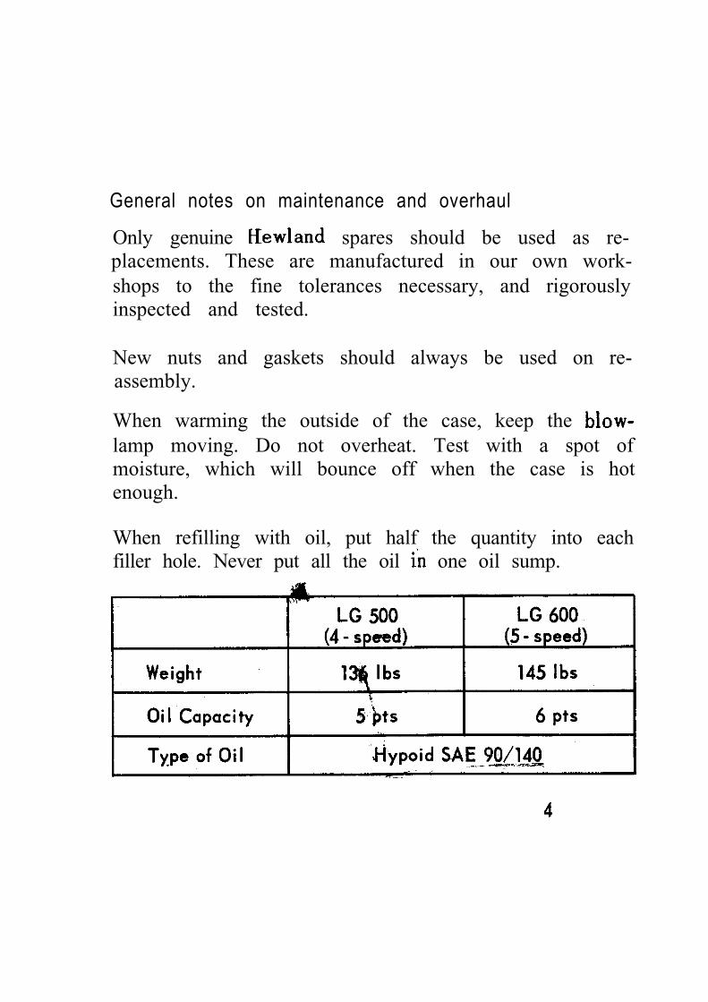
General notes on maintenance and overhaul
Only genuine spares should be used as re-placements. These are manufactured in our own work-shops to the fine tolerances necessary, and rigorouslyinspected and tested.
New nuts and gaskets should always be used on re-assembly.
When warming the outside of the case, keep the lamp moving. Do not overheat. Test with a spot ofmoisture, which will bounce off when the case is hotenough.
When refilling with oil, put half the quantity into eachfiller hole. Never put all the oil one oil sump.
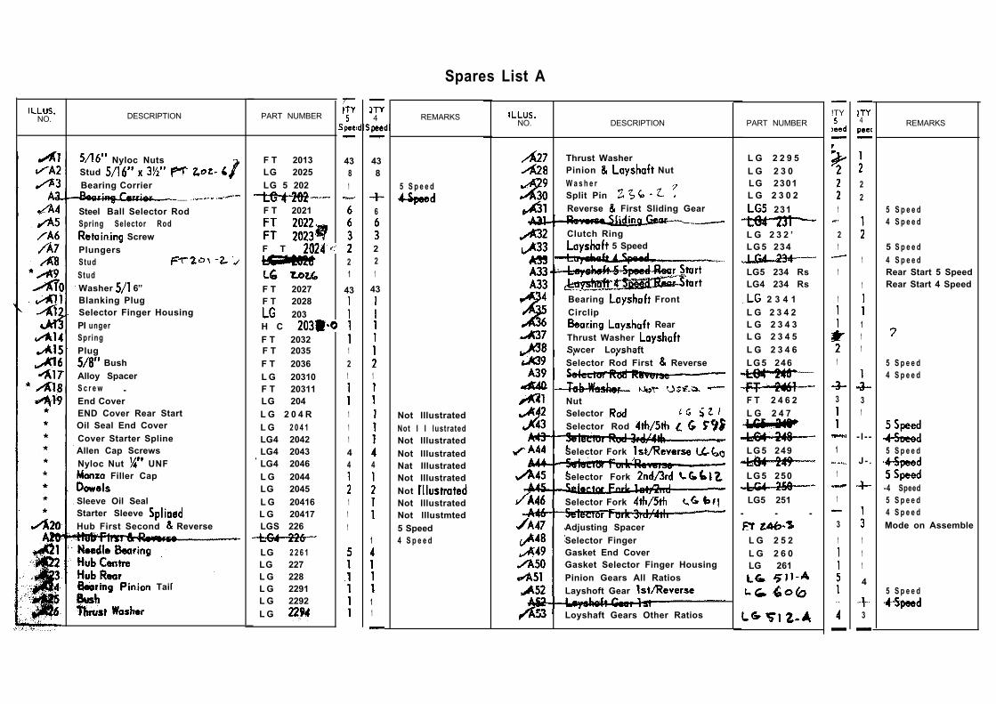
Spares List A
NO. DESCRIPTION PART NUMBER
Nyloc NutsStud Bearing Corrier
___
Steel Ball Selector RodSpring Selector Rod
ScrewPlungersStud
StudWasher 6”Blanking PlugSelector Finger HousingPI ungerSpringPlug
BushAlloy SpacerS c r e w . .End CoverEND Cover Rear StartOil Seal End CoverCover Starter SplineAllen Cap ScrewsNyloc Nut UNF
Filler Cap
Sleeve Oil SealStarter Sleeve Hub First Second Reverse
Tail
F T 2013LG 2025LG 5 202
F T 2021
F T
F T 2027F T 2028
203H C F T 2032F T 2035F T 2036L G 20310F T 20311LG 204L G 2 0 4 RL G 2 0 4 1LG4 2042LG4 2043LG4 2046L G 2044LG 2045L G 20416L G 20417LGS 226
LG 2 2 6 1LG 227L G 228L G 2291L G 2292L G
4381
21
43
121
11144
111
4
438
6
221
43
1
4
1
11
REMARKS
5 S p e e d
Not IllustratedNot I I lustratedNot IllustratedNot IllustratedNat IllustratedNot IllustratedNot Not IllustratedNot lllustmted5 Speed4 S p e e d
NO. DESCRIPTION PART NUMBER
Thrust WasherPinion NutW a s h e rSplit PinReverse First Sliding Gear
Clutch Ring 5 Speed
Bearing FrontCirclip
RearThrust Washer Swcer LovshaftSelector Rod First Reverse
NutSelector
Selector Rod
Selector Fork
LG5 234 RsLG4 234 Rs
2 3 4 1L G 2 3 4 2L G 2 3 4 3L G 2 3 4 5L G 2 3 4 6LG5 246
F T 2 4 6 2L G 2 4 7
LG5 249
Selector Fork LG5 250
Selector Fork
Adjusting SpacerSelector FingerGasket End CoverGasket Selector Finger HousingPinion Gears All RatiosLayshoft Gear
LG5 251- - -
L G 2 5 2L G 2 6 0LG 261
Loyshaft Gears Other Ratios
L G 2 2 9 5L G 2 3 0LG 2301L G 2 3 0 2
231
L G 2 3 2 ’LG5 234
!TY
1
21
1
1
1
3
1
1
1
3
1
4
22
1
1
111
31
- l - -
J - .
111
4
3
REMARKS
5 S p e e d4 S p e e d
5 S p e e d4 S p e e dRear Start 5 SpeedRear Start 4 Speed
5 S p e e d4 S p e e d
5 S p e e d
-4 Speed5 S p e e d4 S p e e dMode on Assemble
5 S p e e d
1 7 I 1 5
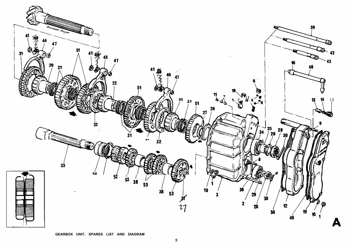
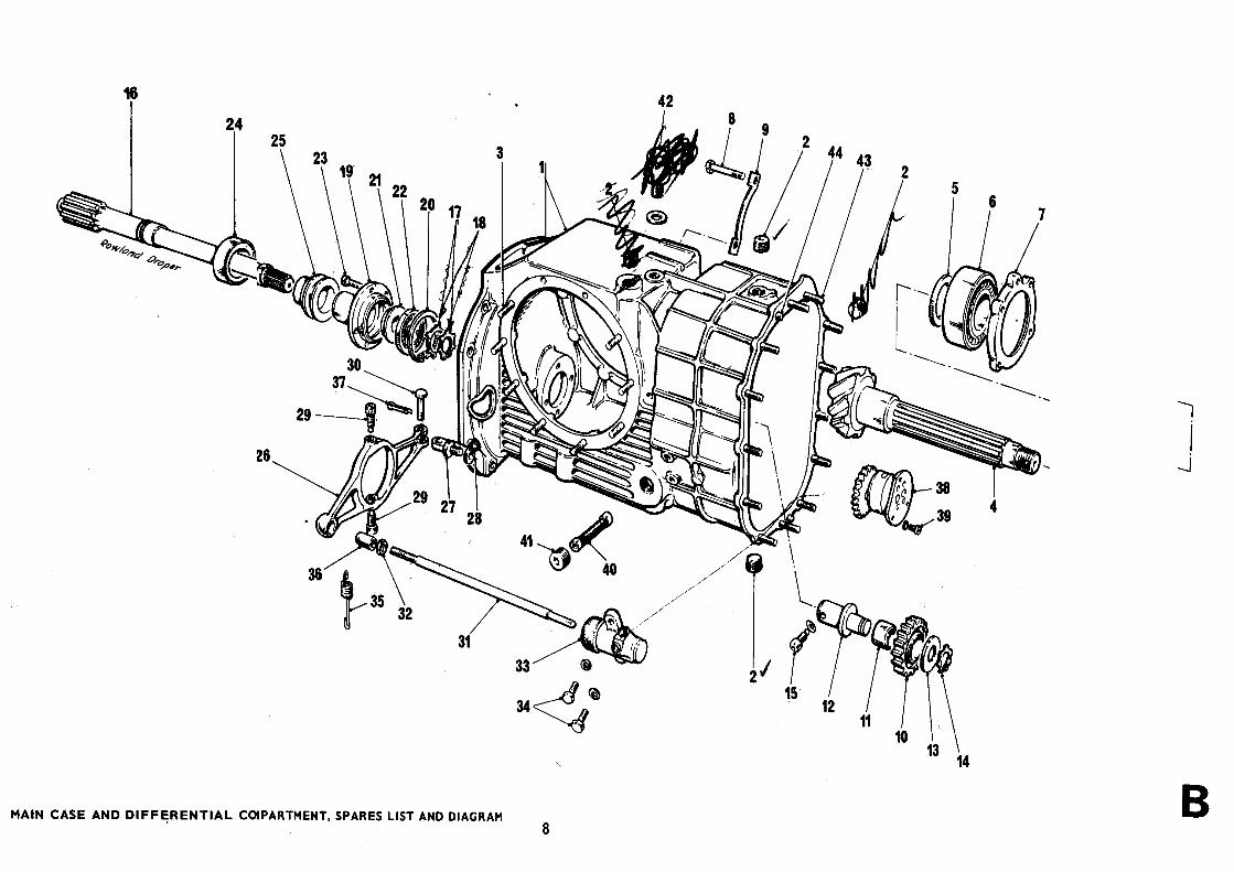
GEARBOX UNIT, SPARES LIST AND DIAGRAM
5
The Gearbox
R E M O V I N G T H E U N I T
END COVER
1.
2.
3.
4.
5.
Remov the nuts and washersfrom t e end cover. Take off cover and gasket.
Remove the split pins from the castellatedpinion and nuts.
Push the heads of the two outside selector rods,thus engaging the gears.
Remove the pinion nut and washer and slackenoff the nut.
Now withdraw the two outside selector rods, todisengage the gears.
BEARING CARRIER
1. Remove the UNF nuts and washers,and the UNC cap screw.
2. Using a plastic mallet, tap the bearing carrierand remove it from the main case, withlay-shaft assembly and gear train. Support thegears, hubs and clutch rings with the hand, asthey come off the pinion.
Replace in reverse order to above.
CHANGING RATIOS
When changing a gear ratio, take off the slackenednut and remove the from the bearing carrier.Gears are exchanged in pairs one from the shaft and one from the pinion shaft. Each gear is
etched with two numbers. The first is the number ofits own teeth. The second is the number of teeth onits mating gear.
It is essential that gears be correctly pairedaccording to these numbers.
S T R I P P I N G T H E G E A R T R A I N
1 .
2.
3.
4.
5.
6.
7.
Remove hubs, clutch rings and gears. Wash andinspect for wear and cracks, giving particularattention to the clutch rings.
Examine forks for heavy or uneven wear, andtest for excessive play between forks and clutchrings.
If forks are not to be stripped, check that nutsare tight and properly tabbed. To continue
Knock back the tab and unscrew the nut from the fork, (44). Remove the fork.
Remove bung, spring and plunger (13, 14, 15)from the selector finger housing.
Remove or by sliding it into the selector head, and pushing the rod
the head is clear of the others.
(On the 4-speed gearbox, to remove selectorfinger it is necessary to undo reverse selectorfork and push rod down until head is clear ofthe others).
Take off the Selector Finger Housing by undoingthe cap screw and two UNF nuts. Thenremove the two remaining forks.
6
8.
9.
10.
Undo the three cap screws (6) and take outthe top Selector Rod Springs and balls. Thentake out the three Selector Rods, followed bythe bottom balls and springs.
Undo the UNC cap screw (11) -and pushout the locking slugs.
Inspect pinion tail bearings andrenew if necessary. To remove, warm up surround-ing area.
Re-assemble in reverse order to above, subject tothe
11.
12.
When replacing bottom balls and springs, set upto correct height. About one-third of the ballshould be exposed. Continue by inserting lockingslugs and selector rods, then top balls andsprings.
Any hub renewed should be identical in lengthwith the original. If replacing all hubs, or mainbearing carrier, check that overall length ofpinion assembly has not been altered. Clearanceis essential to avoid overheating and seizure,but too much clearance will cause excessive wear.
Setting up the selector forks
THE GEARBOX UNIT (continued)
SETT I NG UP THE SELECTO R FO RKS
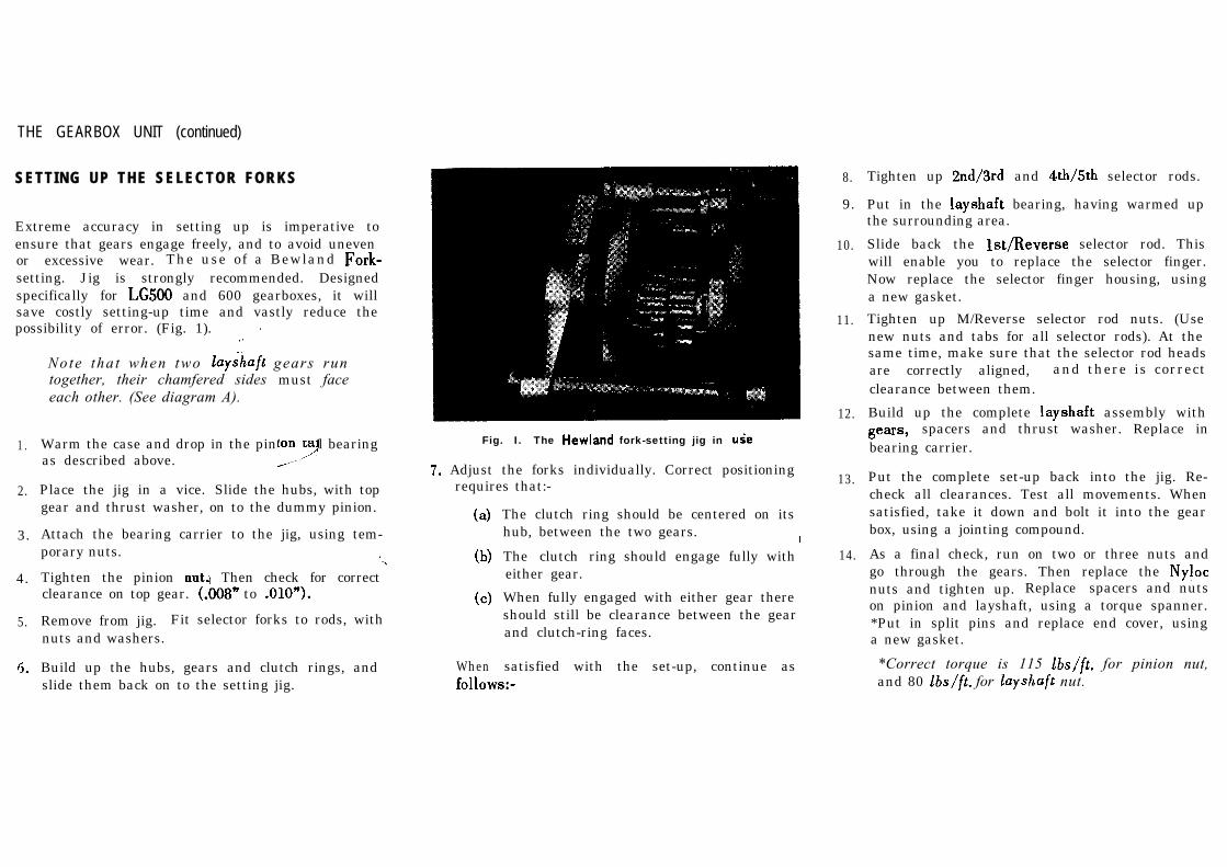
Extreme accuracy in setting up is imperative toensure that gears engage freely, and to avoid unevenor excessive wear. The use of a Bewland setting. Jig is strongly recommended. Designedspecifically for and 600 gearboxes, it willsave costly setting-up time and vastly reduce thepossibility of error. (Fig. 1).
1 .
2.
3.
4.
5.
Note that when two gears runtogether, their chamfered sides must faceeach other. (See diagram A).
Warm the case and drop in the pinion ta’l bearingas described above.
Place the jig in a vice. Slide the hubs, with topgear and thrust washer, on to the dummy pinion.
Attach the bearing carrier to the jig, using tem-porary nuts.
Tighten the pinion Then check for correctclearance on top gear. to
Remove from jig. Fit selector forks to rods, withnuts and washers.
Build up the hubs, gears and clutch rings, andslide them back on to the setting jig.
Fig. I. The fork-setting jig in
Adjust the forks individually. Correct positioningrequires that:-
When
The clutch ring should be centered on itshub, between the two gears.
The clutch ring should engage fully witheither gear.
When fully engaged with either gear thereshould still be clearance between the gearand clutch-ring faces.
satisfied with the set-up, continue as
8.
9.
10.
11.
12.
13.
14.
Tighten up and selector rods.
Put in the bearing, having warmed upthe surrounding area.
Slide back the selector rod. Thiswill enable you to replace the selector finger.Now replace the selector finger housing, usinga new gasket.
Tighten up M/Reverse selector rod nuts. (Usenew nuts and tabs for all selector rods). At thesame time, make sure that the selector rod headsare correctly aligned, and there is correctclearance between them.
Build up the complete assembly withspacers and thrust washer. Replace in
bearing carrier.
Put the complete set-up back into the jig. Re-check all clearances. Test all movements. Whensatisfied, take it down and bolt it into the gearbox, using a jointing compound.
As a final check, run on two or three nuts andgo through the gears. Then replace the nuts and tighten up. Replace spacers and nutson pinion and layshaft, using a torque spanner.*Put in split pins and replace end cover, usinga new gasket.
*Correct torque is 115 for pinion nut,and 80 for nut.
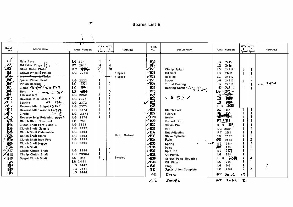
Spares List B
NO. I DESCRIPTION I PART NUMBER
Main CaseOil Filler Plugs Stud Side PloteCrown Wheel Pinion
Spacer Pinion HeadPinion BearingClomp Bolt; Tob WashersReverse Idler Gear Bearing
Reverse Idler Spigot Reverse Idler Washer CirclipReverse Retaining Clutch Shoft ChevroletClutch Shoft Ford J and BClutch Shoft Clutch Shoft OldsmobileClutch BlonkClutch Shaft lndy FordClutch Shoft Clutch ShaftCitclip Clutch ShaftCirclip Clutch ShaftSpigot Clutch Shaft
2 0 1FT 2011F T LG 221B
- -LG 2222
LG 2252LG 2371LG 2372LG 2373LG 2374L G 2 3 7 5LG 2376LG 239LG 2391LG 2392LG 2393LG 2394LG 2395LG 2396
LG 2390LG 2390ALG 244
2 4 4 1LG 2442LG 2443LG 2444
Q T Y Q T Y5 4 REMARKS NO. DESCRIPTION
5 Speed4 Speed
Half Machined
Stondord
LG 2 4 4 1 0LG 24411LG 2 4 4 1 2L-G 2 4 4 1 3
2 4 5 1 3
L G DG 2 5 4Clutch Fork
FulcrumWosherSwivel Bolt
Clevis Pin D G R o d LG 258 ’Nut Adjusting F T 2581Slave Cylinder D G 2 5 8 2
2 5 8 3
Spring D G 2 5 8 4Dome 2 5 9Split Pin D GOil Pump. LG 2 6 5
Screws Pump Mounting L G Oil Filter LG 2 6 6
Plug LG 2661 Union Complete LG 2 6 6 2
Circlip SpigotOil SeolBeor ingScrewsThrust BearingBearing Carrier
PART NUMBER Q T Y 4
SpeedREMARKS
1
14 4
The Main Case and Differential Compartment
DIFFERENTIAL AND DRIVE
1. Take off slave cylinder (33) complete with clutchpush-rod, by removing the two bolts and washers.
2. Take off the left-hand side plate, having removedthe nuts washers of plate and tie-bars.Loosen with light blows from a plastic mallet.
3. Support the complete differential assembly on ahammer shaft, and lift it out of the main case.
4. Remove the right-hand side-plate.
Replace in reverse order to above.
CLUTCH SHAFT
1.
2.
3.
4.
5.
6.
7.
Unhook the spring (35) from the clutch fork clevispin, enabling the fork to swing free.
Slacken off the top and bottom swivel pins (29)and slide the thrust bearing and bearing carrier offthe end of the clutch shaft.
Remove the clutch fork, after taking out thesplit pin and clevis pin.
Remove the four cap countersunk setscrews. Slide out complete clutch shaft assembly.
Remove small circlip and oil pump driver gear.Remove second circlip and press clutch shaftout of spigot housing.
Remove the large circlip then the bearingand the oil seal (22 and 21).
Re-assemble in reverse order to above, and
Fit a new oil seal. Replace any worn parts,giving particular attention to the bearing.
Removal and replacement of units and assemblies
Check that the bearing carrier rotates after tightening down the two swivel pins (9).
9. When bolting the spigot to its housing, put asmear of locking fluid on the four capscrews.
PINION
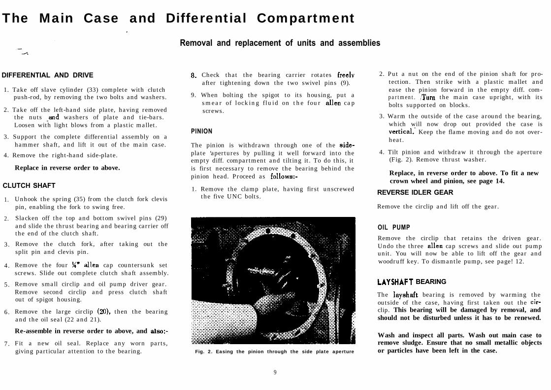
The pinion is withdrawn through one of the plate ‘apertures by pulling it well forward into theempty diff. compartment and tilting it. To do this, itis first necessary to remove the bearing behind thepinion head. Proceed as
1. Remove the clamp plate, having first unscrewedthe five UNC bolts.
Fig. 2. Easing the pinion through the side plate aperture
9
2. Put a nut on the end of the pinion shaft for pro-tection. Then strike with a plastic mallet andease the pinion forward in the empty diff. com-partment. the main case upright, with itsbolts supported on blocks.
3. Warm the outside of the case around the bearing,which will now drop out provided the case is
Keep the flame moving and do not over-heat.
4. Tilt pinion and withdraw it through the aperture(Fig. 2). Remove thrust washer.
Replace, in reverse order to above. To fit a newcrown wheel and pinion, see page 14.
REVERSE IDLER GEAR
Remove the circlip and lift off the gear.
OIL PUMP
Remove the circlip that retains the driven gear.Undo the three cap screws and slide out pumpunit. You will now be able to lift off the gear andwoodruff key. To dismantle pump, see page! 12.
BEARING
The bearing is removed by warming theoutside of the case, having first taken out the clip. This bearing will be damaged by removal, andshould not be disturbed unless it has to be renewed.
Wash and inspect all parts. Wash out main case toremove sludge. Ensure that no small metallic objectsor particles have been left in the case.
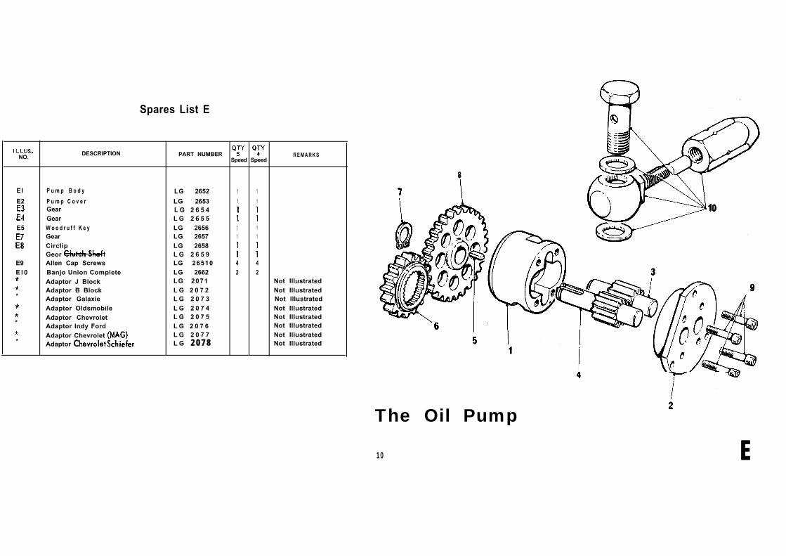
Spares List E
NO.DESCRIPTION PART NUMBER
Speed SpeedR E M A R K S
El P u m p B o d y LG 2652 1 1
E2 P u m p C o v e r LG 2653 1 1Gear L G 2 6 5 4Gear L G 2 6 5 5
E5 W o o d r u f f K e y LG 2656 1 1E6 Gear LG 2657 1 1
Circlip LG 2658Geor L G 2 6 5 9
E9 Allen Cap Screws LG 26510 4 4E l 0 Banjo Union Complete LG 2662 2 2
Adaptor J Block LG 2071 Not IllustratedAdaptor B Block L G 2 0 7 2 Not Illustrated
* Adaptor Galaxie L G 2 0 7 3 Not IllustratedAdaptor Oldsmobile L G 2 0 7 4 Not IllustratedAdaptor Chevrolet L G 2 0 7 5 Not Illustrated
* Adaptor lndy Ford L G 2 0 7 6 Not Illustrated
Adaptor Chevrolet L G 2 0 7 7 Not Illustrated* Adaptor L G 2 0 7 8 Not Illustrated
8
The Oil Pump
10 E
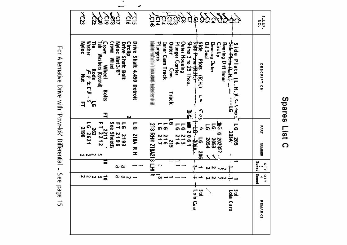
Spares List C
DE
SC
RIP
TIO
NQ
TY
Q
TY
PA
RT
NU
MB
ER
4R
EM
AR
KS
Sid
e Plate (L
.H.)
LG
205 1
1Std
LG
----
LolaCars
2051
LG
LG
2053
2 2
2054
2
2Side
Plots
LG
206 1
1Std
.
---
2
06
1L
G 213
LG
214Outer
Track
LG 215
1
InnerCam Track
LG
216L
G 217
a
Drive Drive Drive Shaft Shafts Shofts Drive 1400 4.450 1400 Shaft Series Series Detroit LG LG LG LG 2191
LH 1 1
1
Drive Shaft 4.450 DetroitL
G
RH
Circlip 2
Drive Shaft BoltLG
2193
a a
FT
21
96
a a
Nyloc Nut Crown
Wheel See Sheet
W
heel Bolts
FT 2211
10
10Tab
Washers (Optional) F T 2 2 1 2 2:
Tie Rods
LG 262
Washer
LG
2621Nyloc
Nut FT
2196
For Alternative Drive with ‘Powr-lok’ Differential See page 15
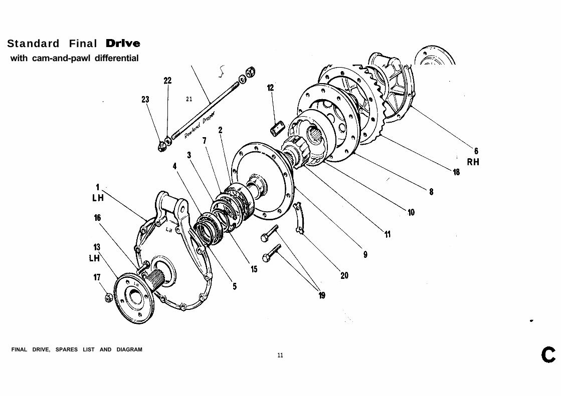
Standard Final with cam-and-pawl differential
21
FINAL DRIVE, SPARES LIST AND DIAGRAM11
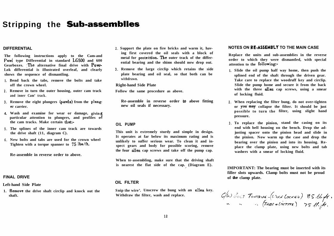
Stripping the
DIFFERENTIAL
The following instructions apply to the Cam-and type Differential in standard and 600
Gearboxes. alternative final drive with Lok differential is illustrated overleaf, and clearlyshows the sequence of dismantling.
1.
2 .
3.
4.
5 .
6 .
Bend back the tabs, remove the bolts and takeoff the crown wheel.
Support the plate on fire bricks and warm it, hav-ing first covered the oil seals with a block ofmetal for outer track of the differ-ential bearing and the shims should now drop out.
Remove the large circlip which retains the sideplate bearing and oil seal, so that both can bewithdrawn.
Remove in turn the outer housing, outer cam trackand inner Cam’ track.
Right-hand Side PlateFollow the same procedure as above.
Remove the eight plungers from the Re-assemble in reverse order above fitting carrier. new oil seals if necessary.
Wash and examine for wear or damage, givinparticular attention to plungers, and profiles othe cam tracks. Make certain
The splines of the inner cam track are towardsthe drive shaft (11, diagram C).
New bolts and tabs are used for the crown wheelTighten with a torque spanner to
OIL PUMP
This unit is extremely sturdy and simple in design.It operates at far below its maximum rating and isunlikely to suffer serious wear. To clean it and in-spect gears and body for possible scoring, removethe four cap screws and take off the pump cap.
Re-assemble in reverse order to above.
FINAL DRIVE
Left-hand Side Plate
1. the drive shaft circlip and knock out theshaft.
2 .
3.
When te-assembling, make sure that the driving shaftis nearest the flat side of the cap. (Diagram E).
OIL FILTER
Snip the wire’. Unscrew the bung with an key.Withdraw the filter, wash and replace.
NOTES ON TO THE MAIN CASE
Replace the units and sub-assemblies in the reverseorder to which they were dismantled, with specialattention to the
1.
2 .
3 .
Slide the oil pump half way home, then push thesplined end of the shaft through the driven gear.Take care to replace the woodruff key and circlip.Slide the pump home and secure it from the backwith the three cap screws, using a smearof locking fluid.
When replacing the filter bung, do not over-tightenor collapse the filter. It should be justpossible to turn the filter, using slight handpressure.
To replace the pinion, stand the casing on itsend with bell housing on the bench. Drop the ad-justing spacer onto the pinion head and slide inthe pinion. Now warm up the case and drop thebearing over the pinion and into its housing. Re-place the clamp plate, using new bolts and tabwashers with a smear of locking fluid.
IMPORTANT: The bearing must be inserted with itsfiller slots upwards. Clamp bolts must not be proudof clamp plate.
12
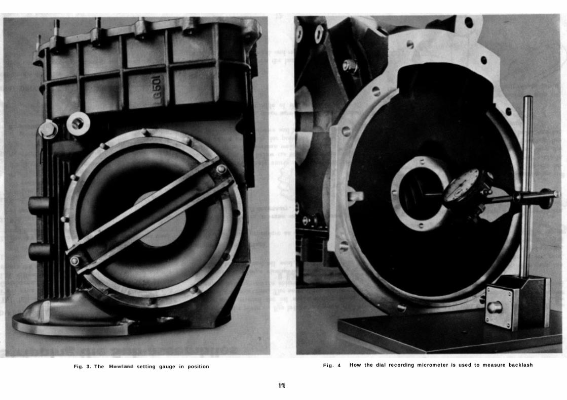
Fig. 3. The setting gauge in position Fig. 4 How the dial recording micrometer is used to measure backlash
a new Crown Wheel and
The crown wheel and pinion are supplied as a pair,precision matched and-lapped. Each-pair is individ-ually tested and passed as perfect before leaving thefactory, and neither part should ever be replacedwithout the other.
Setting up can be done in the usual way, usingengineer’s blue. faster and more positive method,however, is to use the new Setting Gauge.Procedure is as
SETTING UP,USING THE SETTING GUAGEThis operation is carried out with the hubs andspacer on the pinion, and it is important that theyshould be pulled up tight with the pinion nut.
Assemble setting gauge to main case.
Place a parallel bar across the pinion, asillustrated. Hold it flat and square with the pinionface. Measure the clearance between the bar andthe setting gauge (Fig. clearance isetched on the pinion.
3. if necessary by substituting a thicker orthinner spacer. When satisfied, remove settinggauge. Renew clamp plate bolts and tab washers.
TO ADJUST THE PRE-LOAD Assemble differential unit, using the new crown
‘wheel and solid dummy bearings in place of thetwo inner differential bearings (2). The thicknessof the shims is critical. If they have to be re-newed, make sure they are replaced with shimsof same thickness as the originals.
Assemble the differential unit and side platesto the main case. Bolt up, including tie bars, tonormal tension.
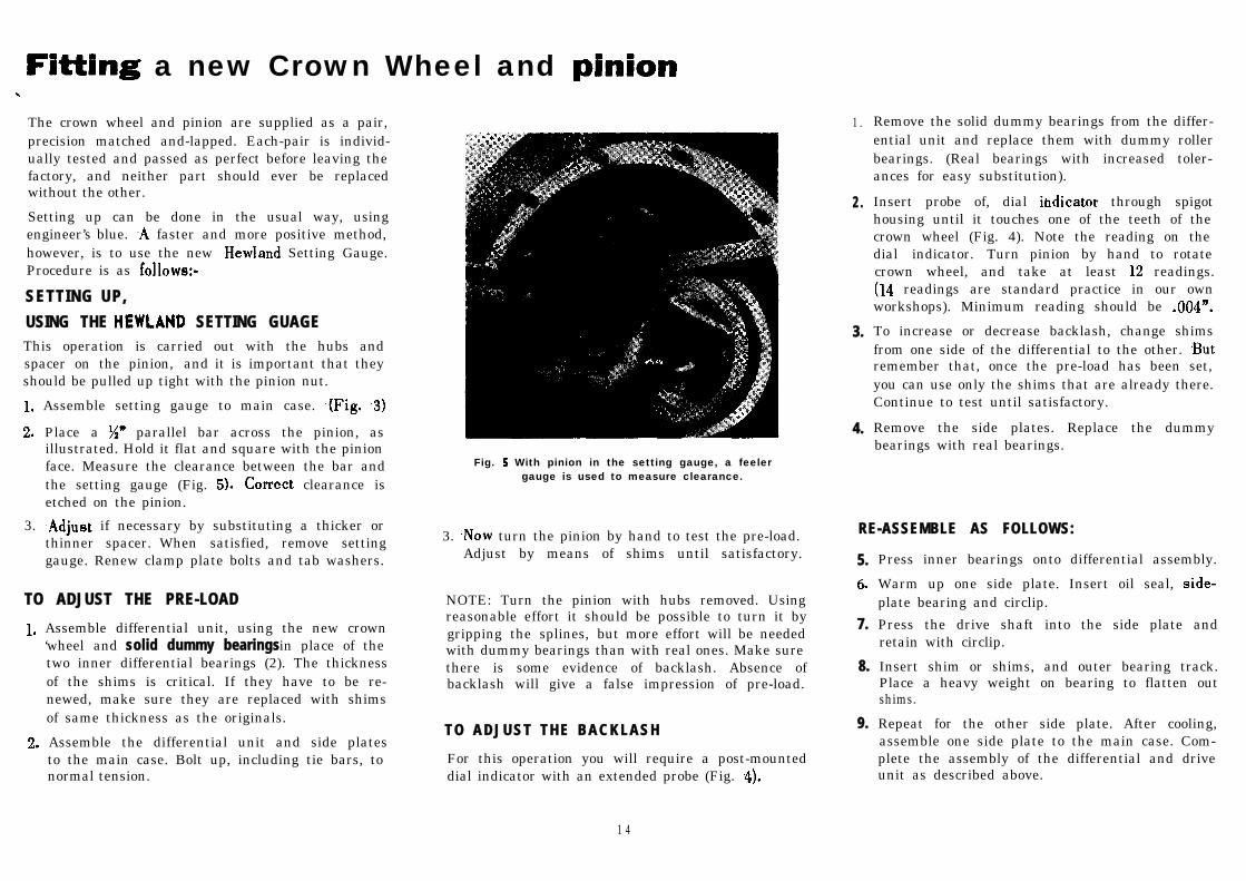
Fig. With pinion in the setting gauge, a feelergauge is used to measure clearance.
3. turn the pinion by hand to test the pre-load.Adjust by means of shims until satisfactory.
NOTE: Turn the pinion with hubs removed. Usingreasonable effort it should be possible to turn it bygripping the splines, but more effort will be neededwith dummy bearings than with real ones. Make surethere is some evidence of backlash. Absence ofbacklash will give a false impression of pre-load.
TO ADJUST THE BACKLASH
For this operation you will require a post-mounteddial indicator with an extended probe (Fig.
1 .
2 .
3.
4.
Remove the solid dummy bearings from the differ-ential unit and replace them with dummy rollerbearings. (Real bearings with increased toler-ances for easy substitution).
Insert probe of, dial through spigothousing until it touches one of the teeth of thecrown wheel (Fig. 4). Note the reading on thedial indicator. Turn pinion by hand to rotatecrown wheel, and take at least readings.
readings are standard practice in our ownworkshops). Minimum reading should be
To increase or decrease backlash, change shimsfrom one side of the differential to the other. remember that, once the pre-load has been set,you can use only the shims that are already there.Continue to test until satisfactory.
Remove the side plates. Replace the dummybearings with real bearings.
RE-ASSEMBLE AS FOLLOWS:
5.
7.
8.
9.
Press inner bearings onto differential assembly.
Warm up one side plate. Insert oil seal, plate bearing and circlip.
Press the drive shaft into the side plate andretain with circlip.
Insert shim or shims, and outer bearing track.Place a heavy weight on bearing to flatten outshims.
Repeat for the other side plate. After cooling,assemble one side plate to the main case. Com-plete the assembly of the differential and driveunit as described above.
1 4
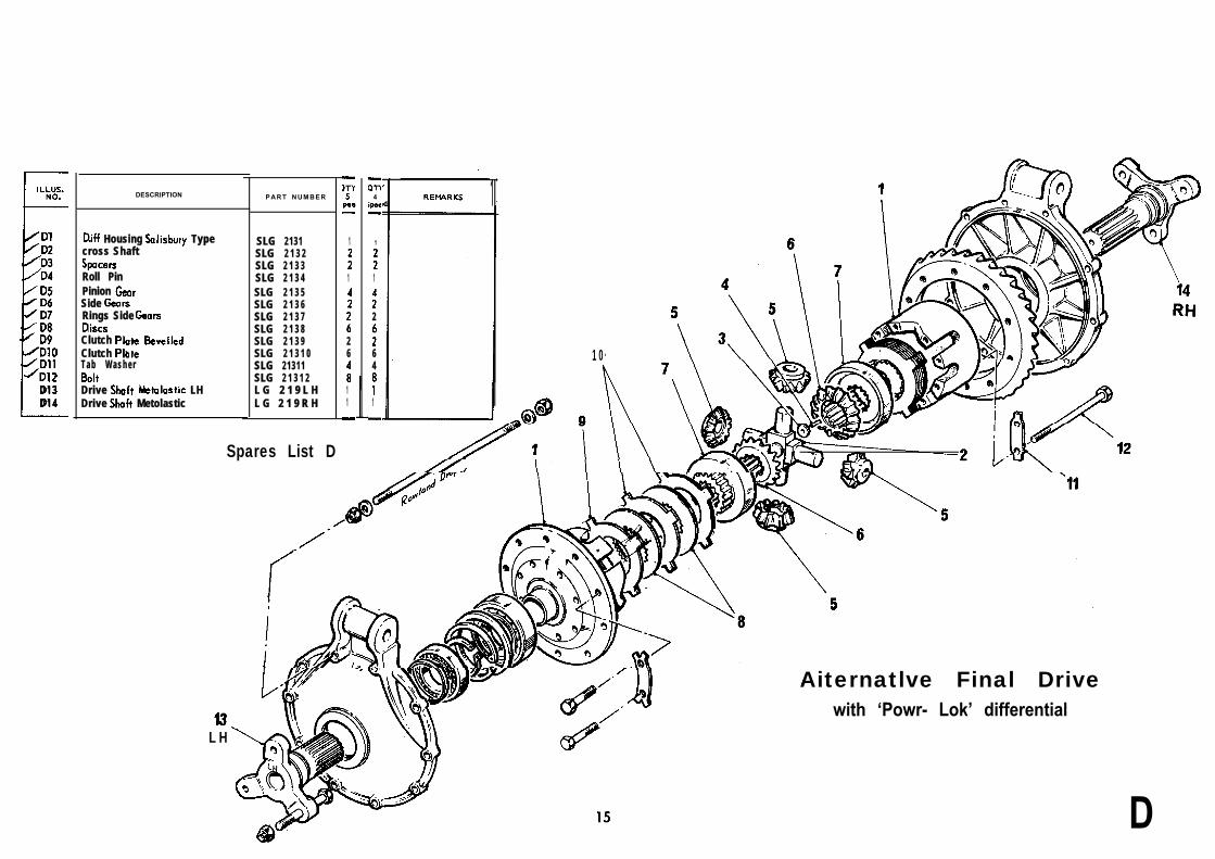
D 2D 3D 4
D 1 3D 1 4
DESCRIPTION
Housing Typecross Shaft
Roll PinPinion Side Rings Side
Clutch Clutch T a b W a s h e r
Drive LHDrive Metolastic
P A R T N U M B E R
SLG 2131SLG 2 1 3 2SLG 2 1 3 3SLG 2 1 3 4SLG 2 1 3 5SLG 2 1 3 6SLG 2 1 3 7SLG 2 1 3 8SLG 2 1 3 9SLG 2 1 3 1 0SLG 21311SLG 2 1 3 1 2L G 2 1 9 L HL G 2 1 9 R H
Spares List D
L H
1
1
26
11
4
1
1
2
64
1
1
1 0
Aiternatlve Final Drivewith ‘Powr- Lok’ differential
D

![U660E AUTOMATIC TRANSMISSION / TRANSAXLE: … · u660e automatic transmission / transaxle: automatic transaxle fluid: adjustment; 2013 my camry [12/2012 -] 1. precautions and work](https://static.fdocuments.in/doc/165x107/5adfe3927f8b9ac0428cc9f3/u660e-automatic-transmission-transaxle-automatic-transmission-transaxle.jpg)