THE SCIENCE OF TORSION, GYROSCOPES AND … OUTLINE v23.pdf3 Figure 3. The total weight of a...
55
1 THE SCIENCE OF TORSION, GYROSCOPES AND PROPULSION attachment for www.SynchronizedUniverse.com Copyright Claude Swanson 2016 SOMETHING IS MISSING IN THE SCIENCE OF SPINNING SYSTEMS If you have ever held a spinning gyroscope in your hand and tried to rotate it, you noticed the surprisingly strong force it exerts. Sometimes it almost seems alive. Gyroscopes fascinated Eric Laithwaite, Professor of Heavy Electrical Engineering, Imperial College of Science and Technology, London, who spent many decades exploring and trying to understand the full range of their behavior. Although physics claims that the gyroscope simply follows Newton's laws, Laithwaite produced Youtube videos in which he executed a rotating motion and easily lifted a forty pound spinning weight at the end of a rod over his head with one hand (Youtube, Laithwaite, 2015). When the weight was not spinning he could barely lift it at all with both hands. He believed and demonstrated (see Figure 1) that gyroscopes produce some type of lifting force that is not understood by science, even after 300 years of Newtonian physics. Figure 1. Prof. Laithwaite showing how the heavy gyro becomes easy to lift when he is rotating the spin axis. He holds the gyro and shaft with only one hand. The rotation of the axis is a form of precession, so he is demonstrating that this "forced precession" causes a lifting force on the gyro. Figure 2a illustrates the familiar concept of 'precession' which is related to this behavior. When a gyro is spinning about an axis it will continue to spin on that axis unless an external force is applied. When the gyro is placed on the floor or on a support, for example, an additional force arises from gravity which pushes down on the gyro. The resulting effect is that the gyroscope begins to "precess." Its axis begins to rotate slowly in a circle as shown in Figure 2a. This behavior is familiar to anyone who ever experimented with a gyroscope or played with a child's spinning top. This type of precession can be explained by Newtonian physics and is a standard exercise in physics. However, 'forced precession' arises when instead of allowing the gyroscope axis to move freely, its motion is forced to move in a certain pattern. This can be done by gears or a motor. This is illustrated in Figure 2b. A simple example would be to have the gyro axis precess at a different rate, either faster or slower. In Laithwaite's demonstration, he simply used his hands to rotate the gyroscope axis of the rod he was holding. This is a
Transcript of THE SCIENCE OF TORSION, GYROSCOPES AND … OUTLINE v23.pdf3 Figure 3. The total weight of a...

1
THE SCIENCE OF TORSION, GYROSCOPES AND PROPULSION
attachment for www.SynchronizedUniverse.com
Copyright Claude Swanson 2016
SOMETHING IS MISSING IN THE SCIENCE OF SPINNING SYSTEMS
If you have ever held a spinning gyroscope in your hand and tried to rotate it, you
noticed the surprisingly strong force it exerts. Sometimes it almost seems alive.
Gyroscopes fascinated Eric Laithwaite, Professor of Heavy Electrical Engineering,
Imperial College of Science and Technology, London, who spent many decades
exploring and trying to understand the full range of their behavior. Although physics
claims that the gyroscope simply follows Newton's laws, Laithwaite produced Youtube
videos in which he executed a rotating motion and easily lifted a forty pound spinning
weight at the end of a rod over his head with one hand (Youtube, Laithwaite, 2015).
When the weight was not spinning he could barely lift it at all with both hands. He
believed and demonstrated (see Figure 1) that gyroscopes produce some type of lifting
force that is not understood by science, even after 300 years of Newtonian physics.
Figure 1. Prof. Laithwaite showing how the heavy gyro becomes easy to lift when he
is rotating the spin axis. He holds the gyro and shaft with only one hand. The rotation
of the axis is a form of precession, so he is demonstrating that this "forced
precession" causes a lifting force on the gyro.
Figure 2a illustrates the familiar concept of 'precession' which is related to this
behavior. When a gyro is spinning about an axis it will continue to spin on that axis
unless an external force is applied. When the gyro is placed on the floor or on a support,
for example, an additional force arises from gravity which pushes down on the gyro. The
resulting effect is that the gyroscope begins to "precess." Its axis begins to rotate slowly
in a circle as shown in Figure 2a. This behavior is familiar to anyone who ever
experimented with a gyroscope or played with a child's spinning top. This type of
precession can be explained by Newtonian physics and is a standard exercise in physics.
However, 'forced precession' arises when instead of allowing the gyroscope axis to
move freely, its motion is forced to move in a certain pattern. This can be done by gears
or a motor. This is illustrated in Figure 2b. A simple example would be to have the gyro
axis precess at a different rate, either faster or slower. In Laithwaite's demonstration, he
simply used his hands to rotate the gyroscope axis of the rod he was holding. This is a
2
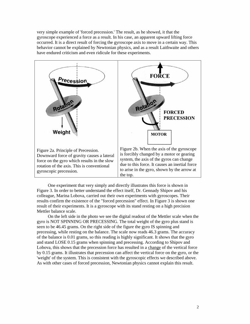
very simple example of 'forced precession.' The result, as he showed, it that the
gyroscope experienced a force as a result. In his case, an apparent upward lifting force
occurred. It is a direct result of forcing the gyroscope axis to move in a certain way. This
behavior cannot be explained by Newtonian physics, and as a result Laithwaite and others
have endured criticism and even ridicule for these experiments.
Figure 2a. Principle of Precession.
Downward force of gravity causes a lateral
force on the gyro which results in the slow
rotation of the axis. This is conventional
gyroscopic precession.
Figure 2b. When the axis of the gyroscope
is forcibly changed by a motor or gearing
system, the axis of the gyros can change
due to this force. It causes an inertial force
to arise in the gyro, shown by the arrow at
the top.
One experiment that very simply and directly illustrates this force is shown in
Figure 3. In order to better understand the effect itself, Dr. Gennady Shipov and his
colleague, Marina Lobova, carried out their own experiments with gyroscopes. Their
results confirm the existence of the "forced precession" effect. In Figure 3 is shown one
result of their experiments. It is a gyroscope with its stand resting on a high precision
Mettler balance scale.
On the left side in the photo we see the digital readout of the Mettler scale when the
gyro is NOT SPINNING OR PRECESSING. The total weight of the gyro plus stand is
seen to be 46.45 grams. On the right side of the figure the gyro IS spinning and
precessing, while resting on the balance. The scale now reads 46.3 grams. The accuracy
of the balance is 0.01 grams, so this reading is highly significant. It shows that the gyro
and stand LOSE 0.15 grams when spinning and precessing. According to Shipov and
Lobova, this shows that the precession force has resulted in a change of the vertical force
by 0.15 grams. It illustrates that precession can affect the vertical force on the gyro, or the
'weight' of the system. This is consistent with the gyroscopic effects we described above.
As with other cases of forced precession, Newtonian physics cannot explain this result.
FORCE

3
Figure 3. The total weight of a gyroscope and pedestal is measured in two
configurations (Lobova, 2013). On the left, the gyro is stopped. The total weight
measured by the highly accurate (0.01 gram) Mettler balance can be seen. It is 46.45
grams. On the right the total weight of the system is measured while the gyroscope is
spinning and precessing. The total weight can be seen to be 46.3 grams. Thus the
gyro and stand have lost 0.15 grams due to its spinning and precession. This is clear
cut proof that precession does alter the force on a gyroscope. Because the precession
is around the vertical axis, therefore the precessional force is in that direction. It is
upward and reduces the total weight of the system. Later we will see how the
magnitude of this force can be computed. We will find that similar effects occur in
many systems that were previously thought to be "anomalous." Later in the paper we
will show that this can be explained due to the force of torsion, a new force that is not
part of Newtonian physics. Torsion often arises when rotating systems undergo
accelerations of angular velocity, as happens during precession.
In spite of the controversy, several inventors have obtained patents on devices
using this principle. The patents claim that tilting or moving the axis of a gyroscope in a
particular way creates a propulsion force which does not require fuel, and can be used to
propel a device or even levitate it. In this way, the gyro produces a force and can change
the velocity and momentum of the vehicle it is attached to. This violates the Newtonian
principle of "conservation of momentum" because the momentum of the vehicle can be
changed without ejecting any matter or exhaust. Because of this, another name for this
mechanism is "non-inertial propulsion."
Some patents which make use of this effect are the Joseph Firmage patent
#US20110185840 A1 (Firmage, 2011. see Figure 4), the Sandy Kidd patent (#5024112,
see Figure 6), and the Neff patent, Patent (# US20030234318 A1, Figure 5). These are
merely a few examples. In the Firmage patent is claimed: "a method of and apparatus for
rectifying momentum of a rotating or spinning mass into linear acceleration forces....The
axis of rotation is moved in a manner to force precession of the rotating mass...to create
linear acceleration..." In other words, the axis of spin of the gyroscopes are forcibly
changed and this generates straight line acceleration in a particular direction. Figure 4
4
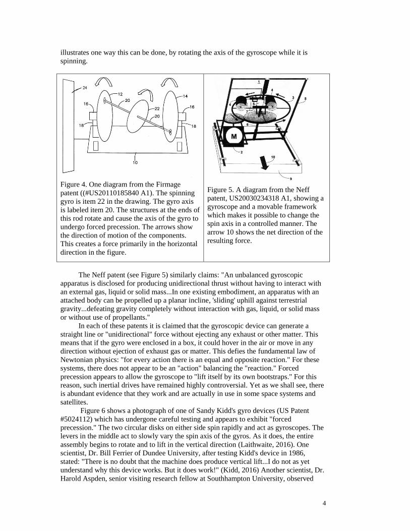
illustrates one way this can be done, by rotating the axis of the gyroscope while it is
spinning.
Figure 4. One diagram from the Firmage
patent ((#US20110185840 A1). The spinning
gyro is item 22 in the drawing. The gyro axis
is labeled item 20. The structures at the ends of
this rod rotate and cause the axis of the gyro to
undergo forced precession. The arrows show
the direction of motion of the components.
This creates a force primarily in the horizontal
direction in the figure.
Figure 5. A diagram from the Neff
patent, US20030234318 A1, showing a
gyroscope and a movable framework
which makes it possible to change the
spin axis in a controlled manner. The
arrow 10 shows the net direction of the
resulting force.
The Neff patent (see Figure 5) similarly claims: "An unbalanced gyroscopic
apparatus is disclosed for producing unidirectional thrust without having to interact with
an external gas, liquid or solid mass...In one existing embodiment, an apparatus with an
attached body can be propelled up a planar incline, 'sliding' uphill against terrestrial
gravity...defeating gravity completely without interaction with gas, liquid, or solid mass
or without use of propellants."
In each of these patents it is claimed that the gyroscopic device can generate a
straight line or "unidirectional" force without ejecting any exhaust or other matter. This
means that if the gyro were enclosed in a box, it could hover in the air or move in any
direction without ejection of exhaust gas or matter. This defies the fundamental law of
Newtonian physics: "for every action there is an equal and opposite reaction." For these
systems, there does not appear to be an "action" balancing the "reaction." Forced
precession appears to allow the gyroscope to "lift itself by its own bootstraps." For this
reason, such inertial drives have remained highly controversial. Yet as we shall see, there
is abundant evidence that they work and are actually in use in some space systems and
satellites.
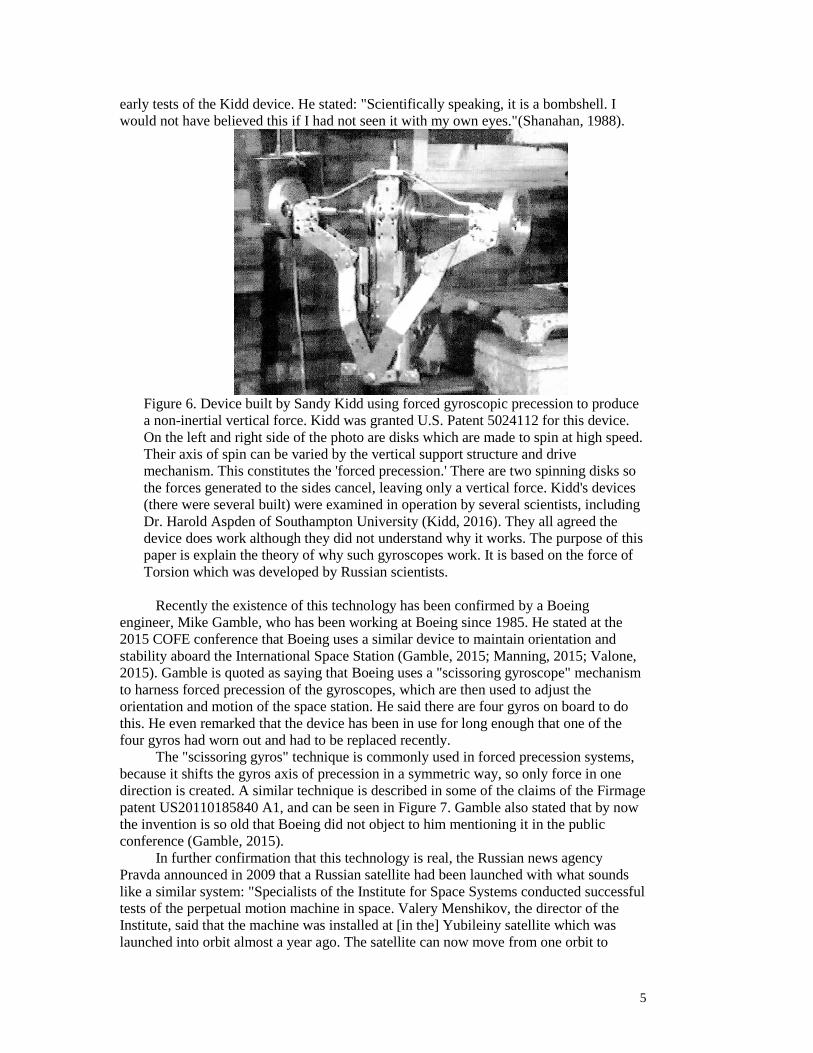
Figure 6 shows a photograph of one of Sandy Kidd's gyro devices (US Patent
#5024112) which has undergone careful testing and appears to exhibit "forced
precession." The two circular disks on either side spin rapidly and act as gyroscopes. The
levers in the middle act to slowly vary the spin axis of the gyros. As it does, the entire
assembly begins to rotate and to lift in the vertical direction (Laithwaite, 2016). One
scientist, Dr. Bill Ferrier of Dundee University, after testing Kidd's device in 1986,
stated: "There is no doubt that the machine does produce vertical lift...I do not as yet
understand why this device works. But it does work!" (Kidd, 2016) Another scientist, Dr.
Harold Aspden, senior visiting research fellow at Southhampton University, observed
5
early tests of the Kidd device. He stated: "Scientifically speaking, it is a bombshell. I
would not have believed this if I had not seen it with my own eyes."(Shanahan, 1988).
Figure 6. Device built by Sandy Kidd using forced gyroscopic precession to produce
a non-inertial vertical force. Kidd was granted U.S. Patent 5024112 for this device.
On the left and right side of the photo are disks which are made to spin at high speed.
Their axis of spin can be varied by the vertical support structure and drive
mechanism. This constitutes the 'forced precession.' There are two spinning disks so
the forces generated to the sides cancel, leaving only a vertical force. Kidd's devices
(there were several built) were examined in operation by several scientists, including
Dr. Harold Aspden of Southampton University (Kidd, 2016). They all agreed the
device does work although they did not understand why it works. The purpose of this
paper is explain the theory of why such gyroscopes work. It is based on the force of
Torsion which was developed by Russian scientists.
Recently the existence of this technology has been confirmed by a Boeing
engineer, Mike Gamble, who has been working at Boeing since 1985. He stated at the
2015 COFE conference that Boeing uses a similar device to maintain orientation and
stability aboard the International Space Station (Gamble, 2015; Manning, 2015; Valone,
2015). Gamble is quoted as saying that Boeing uses a "scissoring gyroscope" mechanism
to harness forced precession of the gyroscopes, which are then used to adjust the
orientation and motion of the space station. He said there are four gyros on board to do
this. He even remarked that the device has been in use for long enough that one of the
four gyros had worn out and had to be replaced recently.
The "scissoring gyros" technique is commonly used in forced precession systems,
because it shifts the gyros axis of precession in a symmetric way, so only force in one
direction is created. A similar technique is described in some of the claims of the Firmage
patent US20110185840 A1, and can be seen in Figure 7. Gamble also stated that by now
the invention is so old that Boeing did not object to him mentioning it in the public
conference (Gamble, 2015).
In further confirmation that this technology is real, the Russian news agency
Pravda announced in 2009 that a Russian satellite had been launched with what sounds
like a similar system: "Specialists of the Institute for Space Systems conducted successful
tests of the perpetual motion machine in space. Valery Menshikov, the director of the
Institute, said that the machine was installed at [in the] Yubileiny satellite which was
launched into orbit almost a year ago. The satellite can now move from one orbit to
6
another with the help of the engine, which discharges no reaction mass. The first tests
were conducted in June and July of 2008. The tests revealed some problems that need
further developments of the machine, but the orbital experiment was conducted
successfully in general. The new engine lasts for 15 years and can be started about
300,000 times. It uses solar batteries for its power, engineers at the institute said."
(Pravda, 2009; Clark, 2008)
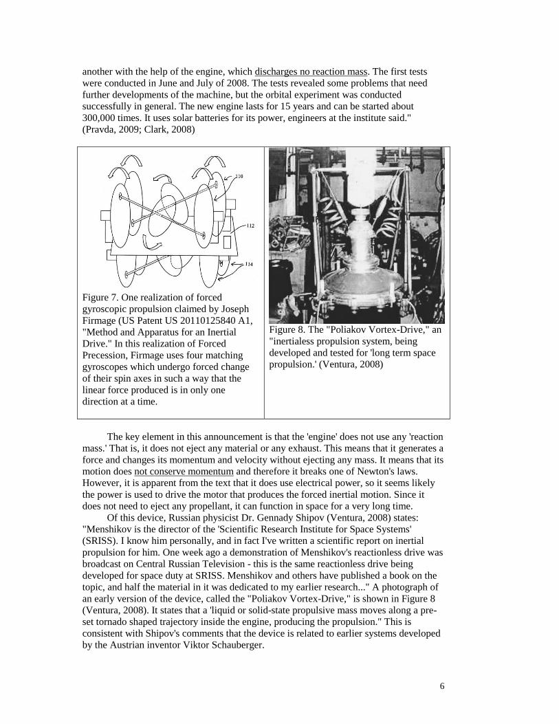
Figure 7. One realization of forced
gyroscopic propulsion claimed by Joseph
Firmage (US Patent US 20110125840 A1,
"Method and Apparatus for an Inertial
Drive." In this realization of Forced
Precession, Firmage uses four matching
gyroscopes which undergo forced change
of their spin axes in such a way that the
linear force produced is in only one
direction at a time.
Figure 8. The "Poliakov Vortex-Drive," an
"inertialess propulsion system, being
developed and tested for 'long term space
propulsion.' (Ventura, 2008)
The key element in this announcement is that the 'engine' does not use any 'reaction
mass.' That is, it does not eject any material or any exhaust. This means that it generates a
force and changes its momentum and velocity without ejecting any mass. It means that its
motion does not conserve momentum and therefore it breaks one of Newton's laws.
However, it is apparent from the text that it does use electrical power, so it seems likely
the power is used to drive the motor that produces the forced inertial motion. Since it
does not need to eject any propellant, it can function in space for a very long time.
Of this device, Russian physicist Dr. Gennady Shipov (Ventura, 2008) states:
"Menshikov is the director of the 'Scientific Research Institute for Space Systems'
(SRISS). I know him personally, and in fact I've written a scientific report on inertial
propulsion for him. One week ago a demonstration of Menshikov's reactionless drive was
broadcast on Central Russian Television - this is the same reactionless drive being
developed for space duty at SRISS. Menshikov and others have published a book on the
topic, and half the material in it was dedicated to my earlier research..." A photograph of
an early version of the device, called the "Poliakov Vortex-Drive," is shown in Figure 8
(Ventura, 2008). It states that a 'liquid or solid-state propulsive mass moves along a pre-
set tornado shaped trajectory inside the engine, producing the propulsion." This is
consistent with Shipov's comments that the device is related to earlier systems developed
by the Austrian inventor Viktor Schauberger.
7
The Russian technology appears to be related to that described by the Boeing
engineer Gamble, although it may use spiraling fluids instead of "forced precession
gyroscopes." Later in this paper, we explain how both of these mechanisms depend on
the same physical principle, which depends on the torsion physics described by Shipov
(see Appendix). Like the Boeing design, the Russian system can also be used for
changing orbits and for attitude control. The real advantage of such systems is that the
propellant used by the engines for thrust is never depleted because no material is ever
ejected. This has been a problem in earlier satellites which run out of propellant used for
attitude control. Forced precession enables them to operate for a very long time. This
mechanism has also been confirmed by Russian scientists Shipov and Lobova, who are
familiar with the operation of the Russian satellite system and refer to it in a paper
(Lobova, 2013).
Attacks by the 'Debunkers' and the 'Skeptics'
At the present time, unfortunately, it is probably important to digress for a moment.
If the reader uses Google to investigate topics such as "forced precession" or "torsion" he
will find numerous articles attacking both of these phenomena, claiming that they are not
real, or perhaps even that they are part of some 'fraud' or 'scam.' A variety of very harsh
attacks have been leveled at these subjects and at some of the leading researchers.
Frequently these attacks attribute dishonest motives to the scientists involved, and in
several cases construct false and misleading 'histories' of the development of these
subjects. These accounts diverge very widely from the actual facts regarding torsion, so if
the reader exercises some effort in doing the background research, it is easy to dispose of
such negative attacks. However the casual reader often has difficulty in sorting out the
truth in such cases. It seems likely that one purpose of such attacks is to discourage the
casual reader from investigating the subject further, and may also make potential
academic scientists afraid of becoming involved. And that may their purpose.
The most frequent criticism leveled at 'forced precession' is that it violates
Newton's Third Law. Well, that is a given. The important question is whether Newton's
Third Law fails in some cases involving gyroscopes. This is a scientific question, and
should be addressed scientifically, not with rhetoric. Experiments like Lobova's shown in
Figure 3 are a possible approach. One can easily devise more elaborate and sensitive
tests. This is what the skeptics should do if they are interested in scientific truth. Name-
calling has no place in science. Very sincere and honest scientists like Professor
Laithwaite endured a barrage of criticism for simply demonstrating in front of an
audience what seemed to be apparent: that there is a 'lift force' which occurs with
gyroscopes that is not accounted for by Newton's Laws. This is, or should be, a purely
scientific question. Sadly, many of the Internet attacks seem to prefer to resort to ridicule,
which has the effect of shutting down the discussion completely.
The Russian science of 'torsion' is another subject that has received a similar
fusillade from these self-proclaimed skeptics. When one reads the details of their critique,
it is sometimes astounding. They have accused two of the most important scientists in the
Russian torsion program of having colluded in 1980 and 'created' the idea of torsion for
the purpose of making money, to put over a 'fraud' on the public. They imply that Dr.
Gennady Shipov and Dr. Anatoly Akimov were acting alone, and had no scientific basis
for their 'fraudulent' enterprise. If you have studied this subject, as I have, this is an
astonishing fabrication. Both of these scientists have a long and distinguished record of
research, which is backed up by published articles, reports, and patents. Despite this, I
have found variants of this libelous fairy tale on several websites, including sadly
Wikipedia.

8
A Brief History of the Russian Torsion Program
The truth is that the Russian torsion program began with Dr. Nikolai Kozyrev in
the 1950's. As my comprehensive book Life Force (Swanson, 2011) explains, Kozyrev
first saw evidence of torsion in astrophysical data involving binary star systems. He
published a few papers about his ideas (Kozyrev, 1958, 1967, 1978, 1980) mostly in
Russian, and later some of these ideas were tested in published papers by Lavrentiev and
others (Lavrentiev, 1990, 1991, 1992). Dr. Kozyrev was also extensively interviewed by
two Western journalists about his work, and conducted several experiments for them in
his laboratory to explain the nature of the torsion force. He explained that he believed
torsion is the basis for many "anomalous" phenomena such as ESP, PK, and other
paranormal effects. His work is given an entire chapter in their landmark book Psychic
Discoveries Behind the Iron Curtain (Ostrander, 1970).
Very little was published during the 1970's and 1980's until the period of
"openness" when the Berlin Wall came down. Then a flood of papers emerged from
Russia which revealed that extensive research involving dozens or perhaps even hundreds
of scientists had continued during the intervening years. Much of the research had been
conducted in "secret cities" like Novosibirsk, suggesting that at least some of it had been
secret. The list of scientists involved in this research is extensive.
A report by Tomsk University (Lunev, 1995) summarizes research sponsored by
Dr. Akimov, who was one of the directors of the research effort in Russia. Dozens of
scientists are listed along with multiple institutions. This report is only a summary of
many dozens of other reports which provided more detailed descriptions of experiments.
It offers a glimpse into an extensive governmet sponsored research effort that continued
for many years. Another report, by Professor Levich (Levich, 1996), summarizes many of
the findings of the torsion research effort. Again, by the amount of data, and the number
of experiments, and the number of scientists cited, it is clear that this was an extensive
effort conducted with government support and supervision over many years.
Here are a few comments by some of the other scientists who were involved in the
Russian torsion program. Hopefully, these comments will make clear that the torsion
research effort in Russia extended over many years and involved many scientists and
laboratories. It received this level of support because torsion is truly an important subject
with far reaching implications. .
“This physical component of time [the time density] can be ‘absorbed’ or ‘radiated’
by substances. So ‘density’ reflects the active property of time. The experiments
carried out using special detectors showed that near the systems in which entropy
increases, the density of time increases too. Consequently in this process the order,
lost when entropy increases in one system, can be transmitted by changing the
density of time, to the substance of the detector, increasing its order. So the
elasticity, the conductivity, the work function of electrons (in photoelectronic
processes) of the substance changes. These phenomena were confirmed by
experiments (Kozyrev, 1978; Kozyrev, 1980).” (Adamenko, 1989)[Emphasis added]
“Investigation of this effect has shown that samples of the substances placed near
processes, emitting time, then after some time, they themselves have such an effect
on the detector.”(Korotaev, 1995)
“From the late 80’s till the late ‘90s, major experimental investigations were
conducted that confirmed the theoretical predictions. It was established that torsion
generators allow us not only to replicate all “phenomena” demonstrated by so-
9
called “psychics,” but they also are able to demonstrate effects that were never
demonstrated by any “psychic” (Nachalov, 2003).
Dr. Ivan Shakhparonov describes “applied” research he was doing in 1991
(Shakhparonov, 2001). He mentions the coordination of eight scientific teams and
30 years of research which culminated in this effort!
“Spin acts as the source of the torsion field in the same manner as electric
charge and mass produce electromagnetic and gravitation fields,
respectively…A number of devices have been constructed, generating what
appears to be torsion fields.” (Panov, 1997)
“Time does not propagate (for example like electromagnetic waves) but appears at
once all over the Universe. That is why the connection through time must be an
instantaneous one. So it is possible to observe some phenomena of very far
astronomical bodies in real time, without delay. This perspective does not
contradict the special theory of relativity because, when we have instantaneous
connection through time, there are not movements of material objects.” (Kozyrev,
1976)
“N.A. Kozyrev, an outstanding astronomer and natural scientist, enriched the
dynamic picture of the world by introducing a new entity, possessing ‘active
properties,’ and coinciding with neither matter, nor field, nor space-time in its
usual understanding.” (Levich, 1995),
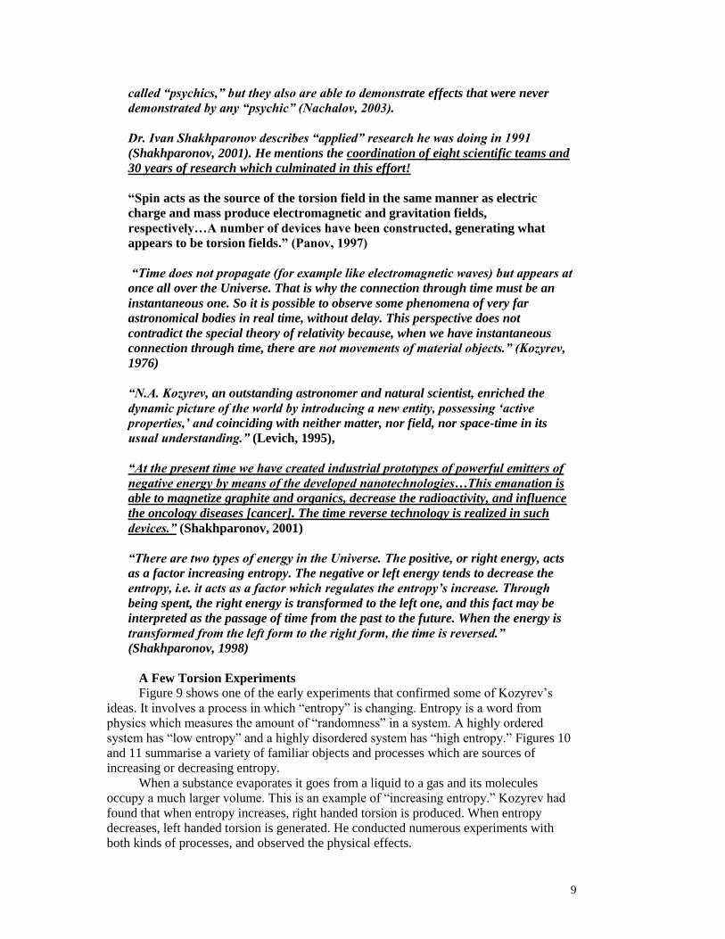
“At the present time we have created industrial prototypes of powerful emitters of
negative energy by means of the developed nanotechnologies…This emanation is
able to magnetize graphite and organics, decrease the radioactivity, and influence
the oncology diseases [cancer]. The time reverse technology is realized in such
devices.” (Shakhparonov, 2001)
“There are two types of energy in the Universe. The positive, or right energy, acts
as a factor increasing entropy. The negative or left energy tends to decrease the
entropy, i.e. it acts as a factor which regulates the entropy’s increase. Through
being spent, the right energy is transformed to the left one, and this fact may be
interpreted as the passage of time from the past to the future. When the energy is
transformed from the left form to the right form, the time is reversed.”
(Shakhparonov, 1998)
A Few Torsion Experiments
Figure 9 shows one of the early experiments that confirmed some of Kozyrev’s
ideas. It involves a process in which “entropy” is changing. Entropy is a word from
physics which measures the amount of “randomness” in a system. A highly ordered
system has “low entropy” and a highly disordered system has “high entropy.” Figures 10
and 11 summarise a variety of familiar objects and processes which are sources of
increasing or decreasing entropy.
When a substance evaporates it goes from a liquid to a gas and its molecules
occupy a much larger volume. This is an example of “increasing entropy.” Kozyrev had
found that when entropy increases, right handed torsion is produced. When entropy
decreases, left handed torsion is generated. He conducted numerous experiments with
both kinds of processes, and observed the physical effects.
10
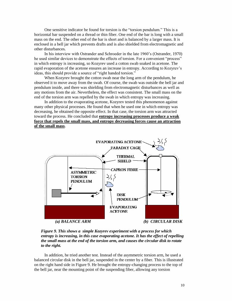
One sensitive indicator he found for torsion is the “torsion pendulum.” This is a
horizontal bar suspended on a thread or thin fiber. One end of the bar is long with a small
mass on the end. The other end of the bar is short and is balanced by a larger mass. It is
enclosed in a bell jar which prevents drafts and is also shielded from electromagnetic and
other disturbances.
In his interview with Ostrander and Schroeder in the late 1960’s (Ostrander, 1970)
he used similar devices to demonstrate the effects of torsion. For a convenient “process”
in which entropy is increasing, so Kozyrev used a cotton swab soaked in acetone. The
rapid evaporation of the acetone ensures an increase in entropy. According to Kozyrev’s
ideas, this should provide a source of “right handed torsion.”
When Kozyrev brought the cotton swab near the long arm of the pendulum, he
observed it to move away from the swab. Of course, the swab was outside the bell jar and
pendulum inside, and there was shielding from electromagnetic disturbances as well as
any motions from the air. Nevertheless, the effect was consistent. The small mass on the
end of the torsion arm was repelled by the swab in which entropy was increasing.
In addition to the evaporating acetone, Kozyrev tested this phenomenon against
many other physical processes. He found that when he used one in which entropy was
decreasing, he obtained the opposite effect. In that case, the torsion arm was attracted
toward the process. He concluded that entropy increasing processes produce a weak
force that repels the small mass, and entropy decreasing forces cause an attraction
of the small mass.
(a) BALANCE ARM (b) CIRCULAR DISK
Figure 9. This shows a simple Kozyrev experiment with a process for which
entropy is increasing, in this case evaporating acetone. It has the effect of repelling
the small mass at the end of the torsion arm, and causes the circular disk to rotate
to the right.
In addition, he tried another test. Instead of the asymmetric torsion arm, he used a
balanced circular disk in the bell jar, suspended in the center by a fiber. This is illustrated
on the right hand side in Figure 9. He brought the entropy-changing process to the top of
the bell jar, near the mounting point of the suspending fiber, allowing any torsion

11
influence to travel down the fiber. In that case he found that entropy increasing
processes caused the disk to rotate to the right, and entropy decreasing processes
caused it to rotate to the left.
So he was able to show that a force exists which is not part of Western physics, and
that can cause attraction or repulsion. He also found that this same force has a twist to it,
which explains the effect on twisting the circular disk. The force that causes the
repulsion has a right hand twist. The one that has an attraction has a left hand twist,
so he called these two influences right handed and left handed torsion.
PROCESSES WHICH INCREASE ENTROPY: “EMIT TIME”
“RIGHT HANDED TORSION”
ENERGY OR ORDER LEAVING THE SYSTEM
Figure 10. Examples of processes which “emit time,” in which entropy increases
and right handed torsion or “negative od” is produced. By definition, in such a
system order is being lost and therefore “time density” is decreasing.
PROCESSES WHICH DECREASE ENTROPY: “ABSORB TIME”
“LEFT HANDED TORSION”
PUTTING ENERGY OR ORDER INTO SYSTEM
Figure 11. Examples of processes which “absorb time,” in which entropy decreases
and left handed torsion or “positive od” is produced.
Kozyrev found that there are many processes which naturally produce torsion. He
concluded that processes in which entropy is increasing produce right hand torsion.
Acetone evaporation, a dying plant, melting ice, chemical reactions are a few examples.
These are illustrated in Figure 10. Some processes do the opposite. They decrease

12
entropy and produce left handed torsion. Examples are stretching rubber bands, a healthy
growing plant, and ice freezing. These are illustrated in Figure 11. So processes that
produce torsion are all around us, but they are fairly weak processes normally. This is
probably why our Western physics has overlooked them. But if one looks closely, as the
Russians did, the effects can be seen.
Russian scientists conducted many experiments to check out Kozyrev’s ideas. They
found that they could isolate the torsion radiation and then focus it on a mass. When they
did this they found that one polarity of this energy would increase the measured weight of
the mass and the other polarity would decrease the mass (Lavrentiev, 1991). These
experiments, like the torsion balance experiments above, are all delicate and must be
conducted with the most stringent experimental controls, because temperature and many
other effects can cloud the results. The effect of torsion in these cases is usually weak,
which explains why it has been overlooked until now in Western physics. Figure 12
shows some of these results.
0 20 40 60 80 100 120
38775
38780
38785
38790
SR
SR
SL
SL
INDICATES
MASS CHANGE
M
IRREVERSIBLE PROCESS AFFECTS MASS
4
3
2
1
M
M
M
M
EXTERNAL
IRREVERSIBLE
PROCESS
BEGINS
MA
SS
(m
illig
ram
s)
TIME (MIN) Figure 12. Four curves are plotted on the graph, corresponding to four different
cases. The first and fourth from top down are caused by torsion radiation from
entropy decreasing processes which produce left handed torsion, SL. The second
and third cases are caused by entropy increasing processes, which generate right
handed torsion, SR. The horizontal axis is time, in minutes. (Lavrentiev, 1991),
described in (Swanson, 2011)
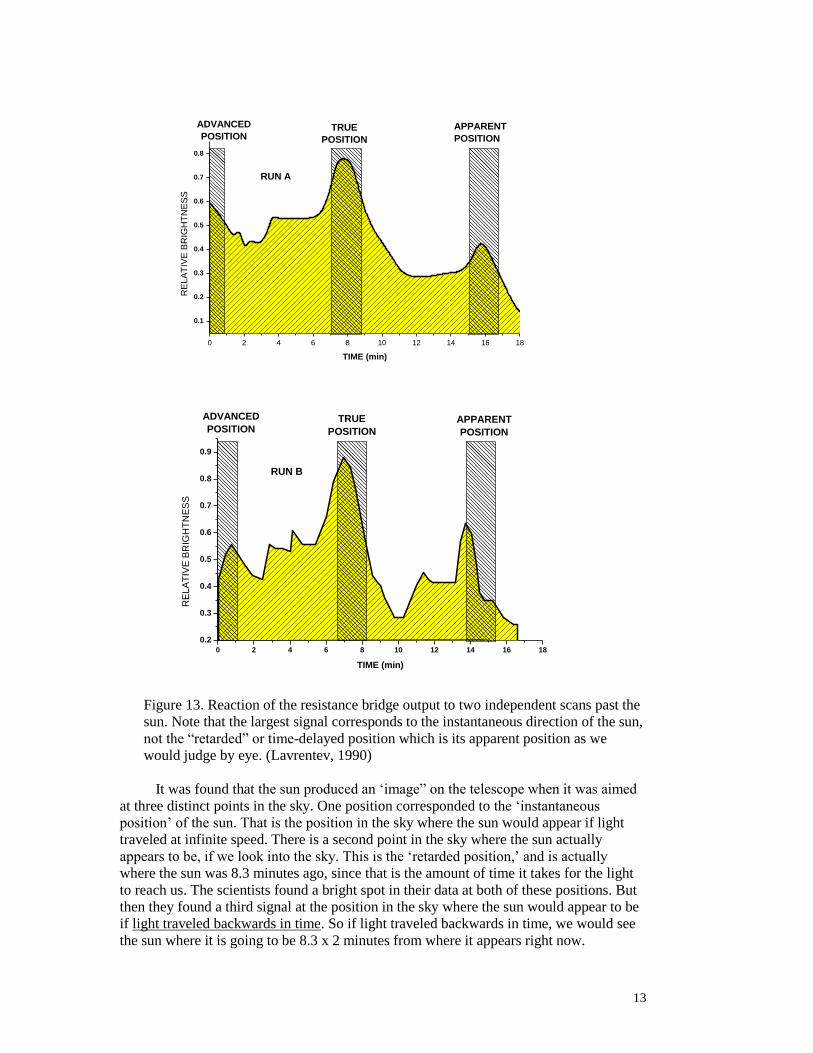
Another interesting experiment used a large reflecting telescope, over which was
placed an opaque cover which blocked out all conventional forms of energy, such as light
and heat. A special detector was mounted at the focal point of the mirror that would
detect torsion energy. The dish was aimed skyward toward the arc in the sky which is
followed by the sun, so at a certain point during the day the telescope is aimed directly at
the sun. It could be operated during daytime, since the telescope mirror was completely
covered and blocked from all known forms of light and heat. (Lavrentiev, 1990).
13
0 2 4 6 8 10 12 14 16 18
0.1
0.2
0.3
0.4
0.5
0.6
0.7
0.8
RUN A
ADVANCED
POSITIONTRUE
POSITION
APPARENT
POSITION
RE
LA
TIV
E B
RIG
HT
NE
SS
TIME (min)
0 2 4 6 8 10 12 14 16 18
0.2
0.3
0.4
0.5
0.6
0.7
0.8
0.9
RUN B
ADVANCED
POSITIONTRUE
POSITION
APPARENT
POSITION
RE
LA
TIV
E B
RIG
HT
NE
SS
TIME (min)
Figure 13. Reaction of the resistance bridge output to two independent scans past the
sun. Note that the largest signal corresponds to the instantaneous direction of the sun,
not the “retarded” or time-delayed position which is its apparent position as we
would judge by eye. (Lavrentev, 1990)
It was found that the sun produced an ‘image” on the telescope when it was aimed
at three distinct points in the sky. One position corresponded to the ‘instantaneous
position’ of the sun. That is the position in the sky where the sun would appear if light
traveled at infinite speed. There is a second point in the sky where the sun actually
appears to be, if we look into the sky. This is the ‘retarded position,’ and is actually
where the sun was 8.3 minutes ago, since that is the amount of time it takes for the light
to reach us. The scientists found a bright spot in their data at both of these positions. But
then they found a third signal at the position in the sky where the sun would appear to be
if light traveled backwards in time. So if light traveled backwards in time, we would see
the sun where it is going to be 8.3 x 2 minutes from where it appears right now.
14
So they found three peaks in their measurements. This shows that torsion is very
unusual. Not only did it penetrate all of the shielding of the telescope cover to reach the
detector, but it appears to have at least two components: one that goes backwards in time
and one that goes forwards in time. The middle peak could be caused by waves which
are a combination of the two, yielding a signal that travels at infinite velocity. This makes
torsion very unique.
However, this behavior may be very helpful if we want to understand paranormal
phenomena. There are many paranormal phenomena that also involve time in a strange
way. Some healers have sent effects into the future. There are healing experiments in
which people have been able to heal people in the future, or heal them in the past. Also,
when you do remote viewing, you can pick your target at any point in space or time. It
does not matter.
So there are many phenomena involving consciousness in which the ability to shift
in time is an important part of the process. And torsion offers an explanation for how that
can happen. When the Soviet government became interested in Kozyrev’s discoveries in
the nineteen-sixties, it apparently began several decades of research on torsion. We only
know about it now because it became public in the early nineties during glaznost when
the Soviet Union dissolved and this information was released.
9 6 7
L
1 2 3 4 5 6
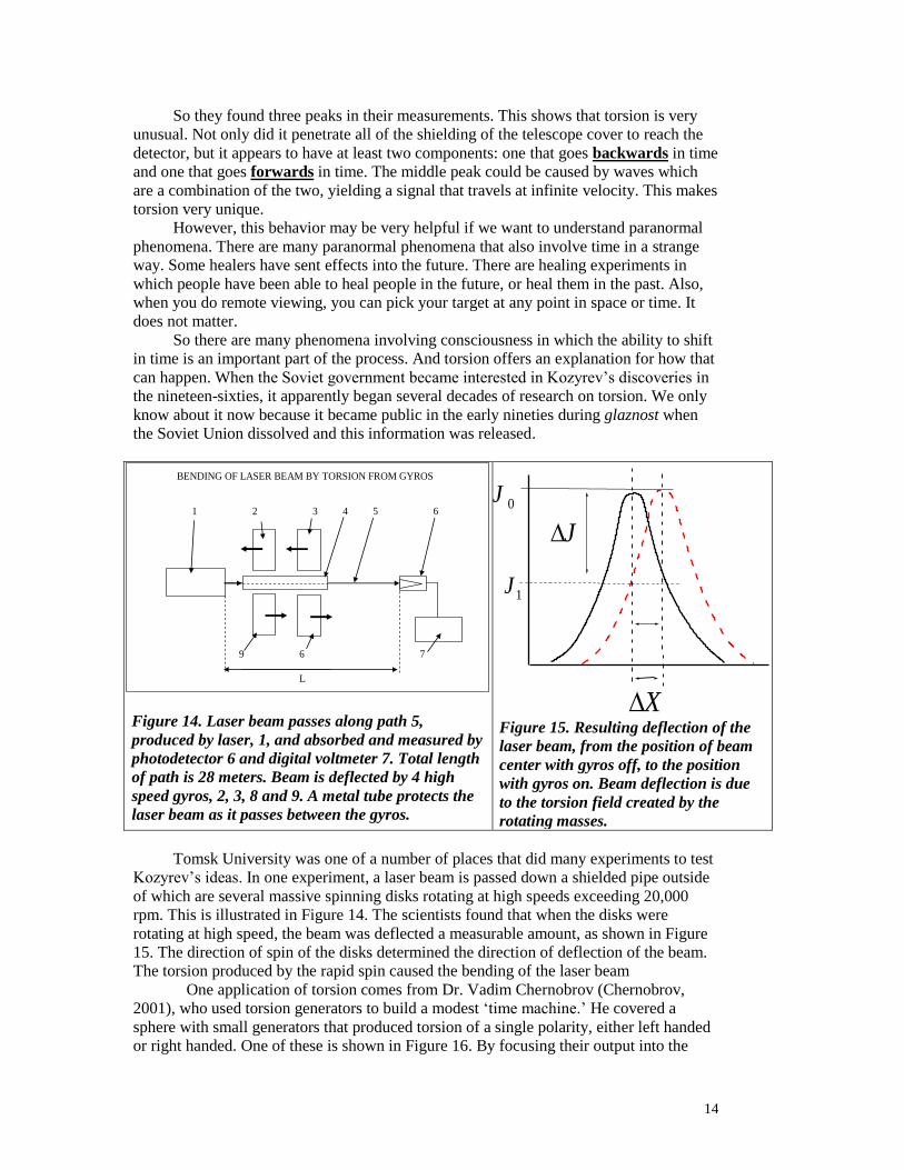
BENDING OF LASER BEAM BY TORSION FROM GYROS
Figure 14. Laser beam passes along path 5,
produced by laser, 1, and absorbed and measured by
photodetector 6 and digital voltmeter 7. Total length
of path is 28 meters. Beam is deflected by 4 high
speed gyros, 2, 3, 8 and 9. A metal tube protects the
laser beam as it passes between the gyros.
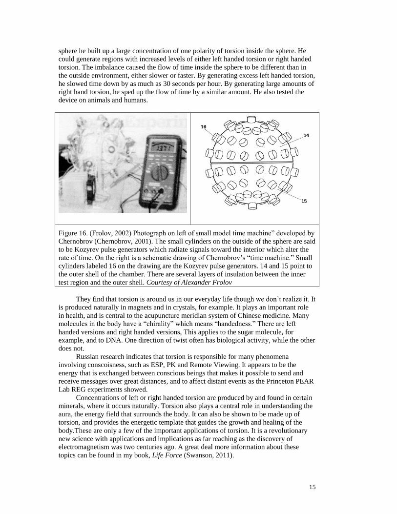
X
0J
1J
J
Figure 15. Resulting deflection of the
laser beam, from the position of beam
center with gyros off, to the position
with gyros on. Beam deflection is due
to the torsion field created by the
rotating masses.
Tomsk University was one of a number of places that did many experiments to test
Kozyrev’s ideas. In one experiment, a laser beam is passed down a shielded pipe outside
of which are several massive spinning disks rotating at high speeds exceeding 20,000
rpm. This is illustrated in Figure 14. The scientists found that when the disks were
rotating at high speed, the beam was deflected a measurable amount, as shown in Figure
15. The direction of spin of the disks determined the direction of deflection of the beam.
The torsion produced by the rapid spin caused the bending of the laser beam
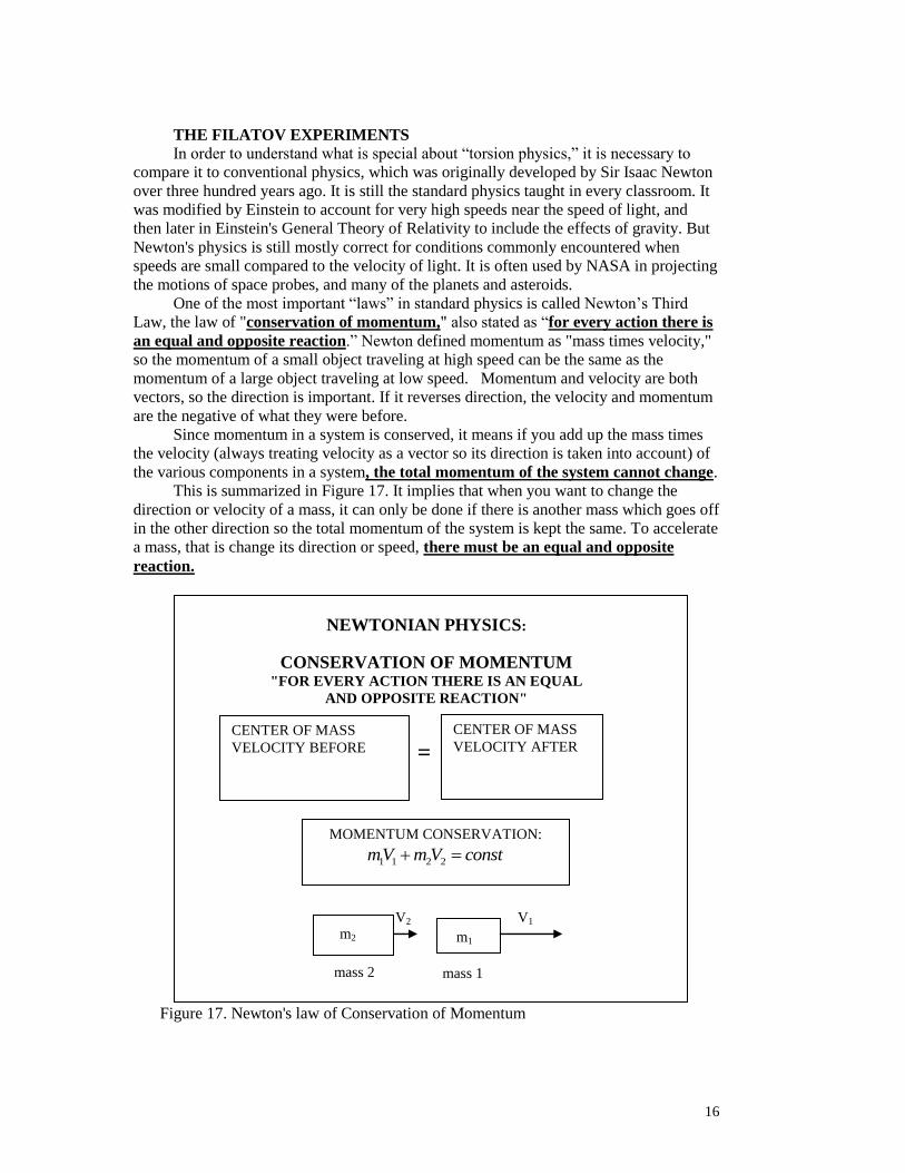
One application of torsion comes from Dr. Vadim Chernobrov (Chernobrov,
2001), who used torsion generators to build a modest ‘time machine.’ He covered a
sphere with small generators that produced torsion of a single polarity, either left handed
or right handed. One of these is shown in Figure 16. By focusing their output into the
15
sphere he built up a large concentration of one polarity of torsion inside the sphere. He
could generate regions with increased levels of either left handed torsion or right handed
torsion. The imbalance caused the flow of time inside the sphere to be different than in
the outside environment, either slower or faster. By generating excess left handed torsion,
he slowed time down by as much as 30 seconds per hour. By generating large amounts of
right hand torsion, he sped up the flow of time by a similar amount. He also tested the
device on animals and humans.
Figure 16. (Frolov, 2002) Photograph on left of small model time machine” developed by
Chernobrov (Chernobrov, 2001). The small cylinders on the outside of the sphere are said
to be Kozyrev pulse generators which radiate signals toward the interior which alter the
rate of time. On the right is a schematic drawing of Chernobrov’s “time machine.” Small
cylinders labeled 16 on the drawing are the Kozyrev pulse generators. 14 and 15 point to
the outer shell of the chamber. There are several layers of insulation between the inner
test region and the outer shell. Courtesy of Alexander Frolov
They find that torsion is around us in our everyday life though we don’t realize it. It
is produced naturally in magnets and in crystals, for example. It plays an important role
in health, and is central to the acupuncture meridian system of Chinese medicine. Many
molecules in the body have a “chirality” which means “handedness.” There are left
handed versions and right handed versions, This applies to the sugar molecule, for
example, and to DNA. One direction of twist often has biological activity, while the other
does not.
Russian research indicates that torsion is responsible for many phenomena
involving conscoisness, such as ESP, PK and Remote Viewing. It appears to be the
energy that is exchanged between conscious beings that makes it possible to send and
receive messages over great distances, and to affect distant events as the Princeton PEAR
Lab REG experiments showed.
Concentrations of left or right handed torsion are produced by and found in certain
minerals, where it occurs naturally. Torsion also plays a central role in understanding the
aura, the energy field that surrounds the body. It can also be shown to be made up of
torsion, and provides the energetic template that guides the growth and healing of the
body.These are only a few of the important applications of torsion. It is a revolutionary
new science with applications and implications as far reaching as the discovery of
electromagnetism was two centuries ago. A great deal more information about these
topics can be found in my book, Life Force (Swanson, 2011).
16
THE FILATOV EXPERIMENTS
In order to understand what is special about “torsion physics,” it is necessary to
compare it to conventional physics, which was originally developed by Sir Isaac Newton
over three hundred years ago. It is still the standard physics taught in every classroom. It
was modified by Einstein to account for very high speeds near the speed of light, and
then later in Einstein's General Theory of Relativity to include the effects of gravity. But
Newton's physics is still mostly correct for conditions commonly encountered when
speeds are small compared to the velocity of light. It is often used by NASA in projecting
the motions of space probes, and many of the planets and asteroids.
One of the most important “laws” in standard physics is called Newton’s Third
Law, the law of "conservation of momentum," also stated as “for every action there is
an equal and opposite reaction.” Newton defined momentum as "mass times velocity,"
so the momentum of a small object traveling at high speed can be the same as the
momentum of a large object traveling at low speed. Momentum and velocity are both
vectors, so the direction is important. If it reverses direction, the velocity and momentum
are the negative of what they were before.
Since momentum in a system is conserved, it means if you add up the mass times
the velocity (always treating velocity as a vector so its direction is taken into account) of
the various components in a system, the total momentum of the system cannot change.
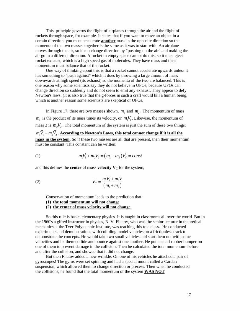
This is summarized in Figure 17. It implies that when you want to change the
direction or velocity of a mass, it can only be done if there is another mass which goes off
in the other direction so the total momentum of the system is kept the same. To accelerate
a mass, that is change its direction or speed, there must be an equal and opposite
reaction.
Figure 17. Newton's law of Conservation of Momentum
CENTER OF MASS
VELOCITY BEFORE
CENTER OF MASS
VELOCITY AFTER =
NEWTONIAN PHYSICS:
CONSERVATION OF MOMENTUM "FOR EVERY ACTION THERE IS AN EQUAL
AND OPPOSITE REACTION"
mass 2 mass 1
m2 m1
11
M1
V2 V1
MOMENTUM CONSERVATION:
1 1 2 2mV m V const
17
This principle governs the flight of airplanes through the air and the flight of
rockets through space, for example. It states that if you want to move an object in a
certain direction, you must accelerate another mass in the opposite direction so the
momenta of the two masses together is the same as it was to start with. An airplane
moves through the air, so it can change direction by "pushing on the air" and making the
air go in a different direction. A rocket in empty space cannot do this, so it must eject
rocket exhaust, which is a high speed gas of molecules. They have mass and their
momentum must balance that of the rocket.
One way of thinking about this is that a rocket cannot accelerate upwards unless it
has something to "push against" which it does by throwing a large amount of mass
downwards at high speed (its exhaust) so the momenta of the two are balanced. This is
one reason why some scientists say they do not believe in UFOs, because UFOs can
change direction so suddenly and do not seem to emit any exhaust. They appear to defy
Newton's laws. (It is also true that the g-forces in such a craft would kill a human being,
which is another reason some scientists are skeptical of UFOs.
In Figure 17, there are two masses shown, 1m and 2m . The momentum of mass
1m is the product of its mass times its velocity, or 1 1mV . Likewise, the momentum of
mass 2 is 2 2m V . The total momentum of the system is just the sum of these two things:
1 1 2 2mV m V . According to Newton's Laws, this total cannot change if it is all the
mass in the system. So if these two masses are all that are present, then their momentum
must be constant. This constant can be written:
(1) 1 1 2 2 1 2 CmV m V m m V const
and this defines the center of mass velocity VC for the system;
(2)
1 1 2
1 2
C
mV m VV
m m
Conservation of momentum leads to the prediction that:
(1) the total momentum will not change
(2) the center of mass velocity will not change.
So this rule is basic, elementary physics. It is taught in classrooms all over the world. But in
the 1960's a gifted instructor in physics, N. V. Filatov, who was the senior lecturer in theoretical
mechanics at the Tver Polytechnic Institute, was teaching this to a class. He conducted
experiments and demonstrations with colliding model vehicles on a frictionless track to
demonstrate the concepts. He would take two small vehicles and start them out with some
velocities and let them collide and bounce against one another. He put a small rubber bumper on
one of them to prevent damage in the collision. Then he calculated the total momentum before
and after the collision, and showed that it did not change.
But then Filatov added a new wrinkle. On one of his vehicles he attached a pair of
gyroscopes! The gyros were set spinning and had a special mount called a Cardan
suspension, which allowed them to change direction or precess. Then when he conducted
the collisions, he found that the total momentum of the system WAS NOT
18
CONSERVED and the CENTER OF MASS VELOCITY WOULD SOMETIMES
CHANGE!
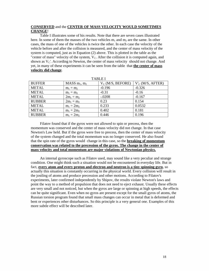
Table I illustrates some of his results. Note that there are seven cases illustrated
here. In some of them the masses of the two vehicles m1 and m2 are the same. In other
cases, the mass of one of the vehicles is twice the other. In each case the velocity of the
vehicle before and after the collision is measured, and the center of mass velocity of the
system is computed, just as in Equation (2) above. This is plotted in the table as the
"center of mass" velocity of the system, VC. After the collision it is computed again, and
shown as VC'. According to Newton, the center of mass velocity should not change. And
yet, in many of these experiments it can be seen from the table that the center of mass
velocity did change.
TABLE I
BUFFER MASS m1, m2 VC (M/S, BEFORE) V'C (M/S, AFTER)
METAL m1 = m2 -0.196 -0.326
METAL m1 = m2 -0.31 -0.16
METAL 2m1 = m2 -.0208 -0.167
RUBBER 2m1 = m2 0.23 0.154
METAL m1 = 2m2 0.233 0.0532
METAL m1 = 2m2 0.402 0.181
RUBBER m1 = 2m2 0.446 0.196
Filatov found that if the gyros were not allowed to spin or precess, then the
momentum was conserved and the center of mass velocity did not change. In that case
Newton's Law held. But if the gyros were free to precess, then the center of mass velocity
of the system changed and the total momentum was no longer conserved. He also found
that the spin rate of the gyros would change in this case, so the breaking of momentum
conservation was related to the precession of the gyros. The change in the center of
mass velocity and total momentum are major violations of Newtonian physics.
An internal gyroscope such as Filatov used, may sound like a very peculiar and strange
condition. One might think such a situation would not be encountered in everyday life. But in
fact, every atom and every proton and electron and neutron is a tiny spinning gyro, so
actually this situation is constantly occurring in the physical world. Every collision will result in
the jostling of atoms and produce precession and other motions. According to Filatov's
experiments, later confirmed independently by Shipov, the results violate Newton's laws and
point the way to a method of propulsion that does not need to eject exhaust. Usually these effects
are very small and not noticed, but when the gyros are large or spinning at high speeds, the effects
can be quite significant. Even when no gyros are present except for the small gyros of atoms, the
Russian torsion program found that small mass changes can occur in metal that is deformed and
bent or experiences other disturbances. So this principle is a very general one. Examples of this
more subtle effect will be described later.

19
Figure 18. Illustration of the Filatov experiment. Again there are colliding model vehicles,
but now one of them carries spinning gyroscopes which are able to precess. In this case,
Filatov found that the momentum of the system IS NOT CONSERVED! The gyros will be
caused to precess when the objects collide, and when the gyros precess, then the total
momentum of the system is changed. This means that an object, or vehicle, which carries
on board gyros can change its own momentum if it can change how its gyros are
precessing. This is called “forced precession.”
Figure 19 illustrates in more detail Filatov’s experiment in which two small vehicles are
allowed to collide on a frictionless track. The top drawing shows a side view and the illustration
below shows the top view. There is a “bumper” on one of them to insure that the collision is not
too violent. One of the vehicles carries two gyroscopes mounted side by side on a special
(Cardan) mount which allows them to precess. In a typical experiment the gyros are initially
spinning in opposite directions at the same angular speed. In a normal collision when no gyros are
present, the total momentum after collision is the same as the total momentum before collision.
Another way of saying this is that the 'center of mass velocity' of the system should not change as
a result of a collision.
But Filatov found that the presence of gyroscopes caused the total momentum after
collision to be different. In other words, the center of mass velocity did change in some of
these experiments. In addition, the gyros underwent precession after collision and this was related
to the amount of momentum and center of mass velocity gained or lost.
The vehicles are allowed to collide. Filatov found that the total momentum after
collision is different than it is before collision if the gyros on board begin precessing as a
result of the collision.
(3) 1 1 2 2mV m V const
mass 2 mass 1
m2
V1 V1
FILATOV'S EXPERIMENTS:
MOMENTUM CONSERVATION
WOULD REQUIRE:
1 1 2 2mV m V const
BUT N.V. FILATOV FOUND THAT MOMENTUM
CONSERVATION DOES NOT HOLD WHEN GYROS
ARE INVOLVED:
1 1 2 2mV m V const
SHIPOV FOUND THAT HE COULD EXPLAIN THESE
RESULTS BY INTRODUCING THE EFFECTS OF
TORSION.
m1

20
Filatov found that from these parameters he could predict the amount of
momentum change in the collision. If he labels this momentum change as P , then over
many experiments he found that the total momentum change of the system could be
described by the formula:
(4)
11 2
1 2
'CM CM
J mchangeof momentum P m m V V
h m m
Figure 19. Overview of Filatov experiment, from (Shipov#7), showing two vehicles
(mass 1m and mass 2m ) moving on a frictionless track, side view (a) and top view
(b).
Here he measured the time of contact of the two masses, which is represented by
and can be thought of as a small time interval when the bumper is in contact with the
other vehicle. The (angular) rotation speed of the gyros before collision is given by ,
and the precession frequency of the gyros after the collision is . The precession before
collision is zero. The symbol h is the height of the gyro which is the distance between the
support point of the gyro and the point of collision. It is the "moment arm" of the
collision. J is the moment of inertia of the gyros. 1m and 2m are the two masses involved
in the collision, where 1m is the mass of the gyros and its carriage.
We can express this force in a simpler way if we assume the moment of inertia J of
the gyro can be written as a mass times a moment arm r, so it becomes
(5) 2
1J m r
where is a constant of order 1, and r is the radius of the gyros.
21
This expression for J can be plugged into the equation, and then the change of
momentum of the system can be computed as a force F acting over the time of collision
. This is an "anomalous" force because it breaks the law of conservation of momentum.
As Shipov explains, it acts as an “outside” or “external” force, accelerating the center of
mass of the system. Shipov shows that it arises from the distortions of the metric
produced by the torsion field, caused by the angular motion of the rotating gyros
(Shipov#7).
The resulting force on the system, from Filatov’s empirical formula for the
momentum change P from Equation (4) above, can then be expressed as:
(6)
2
1 1
1 2
" "m r mP
torsion force F MRh m m
where we have collected together the terms with the dimensions of a characteristic
‘mass”
(7)
2
1
1 2
mM
m m
and those of a characteristic length:
(8)
2rR
h
In this formula, is the spinning frequency of the gyros, and their precession
frequency in radians per second. The expression on the right hand side is a very useful
"rule of thumb" for many cases where "forced precession" occurs. We find the coefficient
to have a value empirically in the range 0.01 to 0.1.
0.01 0.1
Shipov has conducted rigorous mathematical analyses of such gyroscopes, both
theoretically and experimentally, and has found more exact formulas. However, his
results are consistent with this approximation, which is therefore extremely useful for
quick estimates, and will be used later with several examples.
Dr. Gennady Shipov's Theory
The explanation for "forced precession" and how it gives rise to propulsion in
violation of Newton's laws can be found in several of Dr. Shipov's papers, such as
(Shipov#3), (Shipov#4) , (Shipov#6) and (Shipov#7). All of these can be found on his
website, www.shipov.com.
Dr. Shipov also wrote a comprehensive book (Shipov, 1998) which very
thoroughly develops and explains his theory of torsion.
As we explained in Life Force, the Scientific Basis (Swanson, 2011), torsion is the
same energy that was researched by von Reichenbach in the 19th century over several
decades (von Reichenbach, 1850, 1851, 1852). It was rediscovered independently by
Wilhelm Reich (Reich, 1951, 1953, 1954) and Viktor Schauberger (Coats, 1996), each of
whom investigated various aspects of this energy. Kozyrev's discoveries appear to be
22
quite independent of these, but as I show in Life Force, it appears to be the same force
looked at from different perspectives.
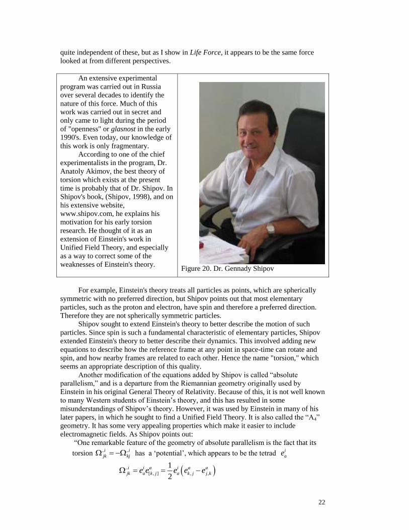
An extensive experimental
program was carried out in Russia
over several decades to identify the
nature of this force. Much of this
work was carried out in secret and
only came to light during the period
of "openness" or glasnost in the early
1990's. Even today, our knowledge of
this work is only fragmentary.
According to one of the chief
experimentalists in the program, Dr.
Anatoly Akimov, the best theory of
torsion which exists at the present
time is probably that of Dr. Shipov. In
Shipov's book, (Shipov, 1998), and on
his extensive website,
www.shipov.com, he explains his
motivation for his early torsion
research. He thought of it as an
extension of Einstein's work in
Unified Field Theory, and especially
as a way to correct some of the
weaknesses of Einstein's theory.
Figure 20. Dr. Gennady Shipov
For example, Einstein's theory treats all particles as points, which are spherically
symmetric with no preferred direction, but Shipov points out that most elementary
particles, such as the proton and electron, have spin and therefore a preferred direction.
Therefore they are not spherically symmetric particles.
Shipov sought to extend Einstein's theory to better describe the motion of such
particles. Since spin is such a fundamental characteristic of elementary particles, Shipov
extended Einstein's theory to better describe their dynamics. This involved adding new
equations to describe how the reference frame at any point in space-time can rotate and
spin, and how nearby frames are related to each other. Hence the name "torsion," which
seems an appropriate description of this quality.
Another modification of the equations added by Shipov is called “absolute
parallelism,” and is a departure from the Riemannian geometry originally used by
Einstein in his original General Theory of Relativity. Because of this, it is not well known
to many Western students of Einstein’s theory, and this has resulted in some
misunderstandings of Shipov’s theory. However, it was used by Einstein in many of his
later papers, in which he sought to find a Unified Field Theory. It is also called the “A4”
geometry. It has some very appealing properties which make it easier to include
electromagnetic fields. As Shipov points out:
“One remarkable feature of the geometry of absolute parallelism is the fact that its
torsion .. ..i i
jk kj has a ‘potential’, which appears to be the tetrad i
ae
..
[ , ] , ,
1
2
i i a i a a
jk a k j a k j j ke e e e e
23
The resulting equations look very similar to Einstein’s Equations of General
Relativity. It is very natural to include electromagnetic effects together with gravity. Most
of the solutions and other effects are very similar.
Shipov found that when the rate of spinning changes from point to point, that
Newton's and Einstein's equations were not sufficiently accurate to describe the
dynamics. There are inertial forces that arise, which appear to be involved with
"anomalous" effects such as "forced precession." Shipov's more accurate analysis of such
interactions identified new forces that had been overlooked in previous theories. He
explained the effect intuitively as arising when rotating frames experience an acceleration
of rotation while also undergoing spatial motion. A very precise mathematical description
was developed which captures this and it leads to Shipov’s successful explanation of the
forced precession of gyroscopes.
An intuitive description of Shipov’s theory can be offered by considering the
actions of elementary particles on the very small scale. Although a particle may be sitting
still, on the very small scale quantum physics tells us that it is undergoing a very rapid
"random walk." At the very small scales, the particle interacts with the zero point energy
of the vacuum, which causes it to rapidly move back and forth. This gives rise to an
uncertainty in its position and velocity which is fundamental to quantum physics.
This is illustrated in Figure 21. A particle is depicted at the quantum level moving
back and forth as it also radiates energy and absorbs energy from the vacuum. This leads
to a “zig zag’ random motion. It is always emitting and absorbing energy. Around every
such particle there is a resulting pattern of energy, a field that is the residual that is left
over from all of the waves going out and the waves coming back. This illustrates, in
Figure 21, what you might imagine for a particle moving along in this environment. It has
a little wake around it of energy that it is in equilibrium with. Since the particle has a
spin, it can be visualized as spinning and rotating as it interacts with this energy field.
If the particle is suddenly impacted by a photons and undergoes acceleration, then
it may leave behind part of that wake. It is that residual wake that gets left behind that is
part of the torsion field.
Therefore, the particle is always interacting with this little wake of energy around
it, which defines its torsion field. This holds the secrets to what matter is, what mass is,
what inertia is, what force is, and also how to go faster than light.
Therefore, the torsion theory that Kozyrev and Shipov describe is related in a
profound way to spin. Every massive particle has a spin. It’s rotating like a child’s top.
As it does so, if that spin changes direction, it produces a torsion wave which keeps it in
balance with the rest of matter in the universe. It preserves the total angular momentum
of the system. That’s the essence of the idea of torsion, which is very important down at
the quantum level because every little particle at the quantum level undergoes these rapid
zig zag motions.
Much of the behavior of the torsion field can be understood intuitively using the
picture we have described so far. It is based on two polarities of torsion wave: one is
“right handed”, spins to the right, and propagates in the time direction toward the future.
It is produced by entropy increasing processes. It tends to push matter away. It is
represented in Figure 22 by an arrow pointing in the “positive time” or “future” direction,
with a curved arrow indicating a twist to the right. The second type of torsion is “left
handed.” It twists to the left and is produced by entropy decreasing processes. It tends to
pull objects toward it and it propagates backwards in time. It is depicted in the right hand
frame, Figure 23.

24
WHEN A PARTICLE ACCELERATES RAPIDLY, IT LEAVES
BEHIND IN ITS WAKE RIPPLES FROM ITS ROTATING ENERGY
PATTERN. WHEN IT MOVES AT CONSTANT SPEED, THE
INCOMING AND OUTGOING RIPPLES ARE IN BALANCE, BUT
WHEN ACCELERATING, THE PARTICLE IS NO LONGER
WHERE THE RETURNING WAVES “THOUGHT” IT WOULD BE.
AS A RESULT, RIPPLES ARE LEFT BEHIND RESEMBLING TINY
VIORTEXES OF FLOW IN THE VACUUM.
PATH OF
PARTICLE
RIPPLES FROM
SPINNING
PARTICLE
Figure 21. When a spinning particle accelerates or changes spin direction, its
radiation field of outgoing and incoming energy is also changed. This can be thought
of as creating tiny whirlpools of vacuum energy which are no longer compensated.
This gives rise to additional “twisting” or torsion in the space itself. This is what
Shipov calls the "inertial field." It is a very real aspect of space-time, and these eddies
play an important role in balancing momentum and angular momentum. It is the
sudden change of spin or rotation which is one of the primary generators of the
torsion field, and which has been overlooked in previous theories.
Shipov developed a mathematical description of torsion in which torsion tensors,
such as those shown in Figure 22 and 23, represent the twisting motion of the frames, and
satisfy rigorous continuity and conservation equations so they conserve total angular
momentum in a consistent way. In this way, Shipov extended Einstein’s equations to
include the freedom of spin and rotation at each point in space time.
Using torsion tensors of this type, Shipov developed a comprehensive theory which
is an extension of Einstein’s equations and includes torsion effects. It is especially useful
in dealing with particles which possess spin, and this includes elementary particles as
well as spinning gyroscopes. The complete set of Shipov’s equations are shown below.
There are 54 equations in 54 unknowns. The great strength of these equations is that they
provide tools to describe the motions of spinning systems quite rigorously.

25
They include four translational equations of motion for the four translational
coordinates ix :
(11)
2
20
i j k j ki i
jk jk
d x dx dx dx dxT
ds ds ds ds ds
plus six rotational equations of motion for the rotational coordinates i
ae :
(12) 0i k k
i j i jajk a jk a
de dx dxe T e
ds ds ds
There are 24 equations that define the twenty four independent components of
Ricci torsion:
(13) ..
[ , ] , ,
1
2
i i a i a a
jk a k j a k j j ke e e e e
and twenty equations which define the twenty independent components of the
Riemann tensor:
(14) [ [] ]2 2 0a a c
bkm k c kb m b mR T T T
Figure 22. Possible intuitive relationship
between the "right handed phiton" picture
and Shipov's "torsion" description.
Figure 23. Possible intuitive relationship
between the "left handed phiton" picture
and Shipov's "torsion" description.
26
This makes a total of 54 equations in 54 unknowns. The torsion field a
bkT connects
the variation in the angular coordinates ab ba to a change in the translation
coordinate kx :
(15) a a k
b bkd T dx
All of the important matter in the universe is made up of spinning objects, protons,
neutrons, electrons: they all have spin. Yet Einstein’s equations were built without spin.
They neglected spin and were constructed for point particles. So Shipov extended
Einstein’s equations to include the effects of torsion and spin.
Shipov’s Theory of Forced Precession
Shipov’s equations can be applied to some practical examples which otherwise our
Western physics cannot calculate. One important phenomenon is called ‘forced
precession’ as we explained earlier. This appears to be a real effect based on experiments,
but if you look it up on the Internet, you will see so much debunking and so much
attacking of this you will be shocked. Forced precession is a very simple idea, and was
described in Figure 2a and 2b above.
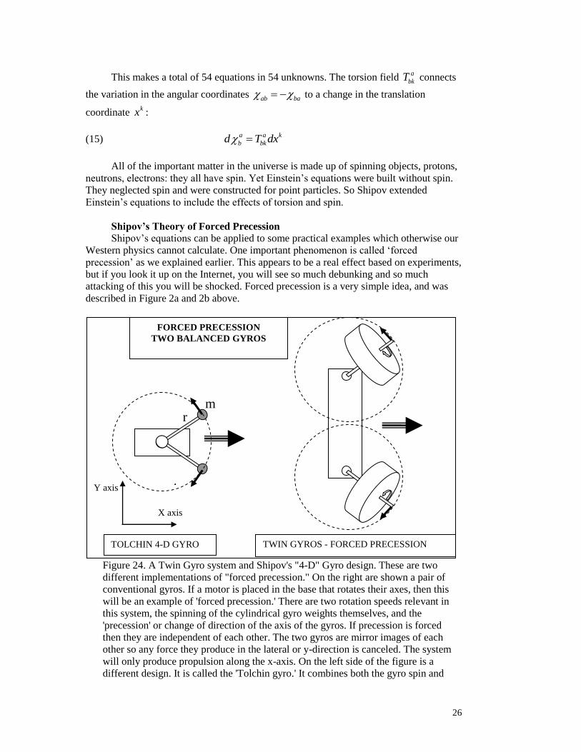
Figure 24. A Twin Gyro system and Shipov's "4-D" Gyro design. These are two
different implementations of "forced precession." On the right are shown a pair of
conventional gyros. If a motor is placed in the base that rotates their axes, then this
will be an example of 'forced precession.' There are two rotation speeds relevant in
this system, the spinning of the cylindrical gyro weights themselves, and the
'precession' or change of direction of the axis of the gyros. If precession is forced
then they are independent of each other. The two gyros are mirror images of each
other so any force they produce in the lateral or y-direction is canceled. The system
will only produce propulsion along the x-axis. On the left side of the figure is a
different design. It is called the 'Tolchin gyro.' It combines both the gyro spin and
TOLCHIN 4-D GYRO TWIN GYROS - FORCED PRECESSION
FORCED PRECESSION
TWO BALANCED GYROS
X axis
Y axis
r m

27
precession in a single device, a mass on a rod. Since each mass is off-center they
produce both gyroscopic forces and precession forces at the same time. This device is
also capable of producing 'non-inertial' propulsion. Experiments with this type of
'forced precession' are described in the text.
Shipov analyzed forced precession using his complete theory, but in addition he
conducted experiments to test his calculations. In doing this he used a special model car
similar to the ones used by Filatov. Shipov developed a variant of the two gyroscope car
in which the gyros were replaced by rotating arms with small masses on the ends. This is
shown in Figure 24. Shipov showed that this was equivalent to a twin gyro system, in that
the lateral forces would be canceled by symmetry, so only forces along the direction of
travel are produced by the gyros. The forces produced in that direction are equivalent for
Shipov’s design, which he called the “4-D” gyro.
In Shipov’s “4-D” gyro the two arms rotate symmetrically in opposite directions so
lateral forces are always zero. The rotation speed can change, and it is this acceleration of
their rotation which gives rise to torsion forces and to “anomalous” acceleration that is
not predicted by Newton. According to Shipov, this angular acceleration gives rise to
torsional forces which are correctly taken into account by the Ricci torsion, and give rise
to forces along the direction of the vehicle, called here the ‘x’ direction. This acceleration
is due to the curvature of the space-time frame induced by the torsion effects. It is an
effect totally unlike any predicted by Newtonian or even Einsteinian theory. The resulting
force is given by:
(16) 22 2
sin cos2 2
1 sinin
NNF M m B
kk
from (Shipov #7), where N has the units of frequency squared:
(17) 22
LN
mr
Note that the term N describes the precession effects since it expresses the change
in spinning frequency of the gyro. The term B is a length made up from the dimensions of
the gyro and its support. The total mass of the vehicle in Shipov’s experiments is
2M m . The other terms are of order 1 and take into account the exact geometry of
the vehicle. Therefore we may simplify this expression for use as a very rough “rule of
thumb” in estimating cases of forced precession, by approximating the variables:
(18) 2 2M m M
(19) B R
(20) 2N
(21) 2 22 2
sin cos
1 sin
N
kk

28
(22)
This enables us to simplify Shipov’s ‘forced precession’ formula, Equation (16), to
obtain the same simple formula we found from the Filatov experiment:
(23)
Shipov analyzes this problem in much greater detail, but with the same
approximate result. His theory of torsion appears to successfully predict the Filatov data
as well as other experiments which he and others have carried out. They predict a force
which accelerates the center of mass of the system. It is produced by distortions in the
metric, due to the torsion created. To verify this idea, Shipov conducted a series of
experiments using his "4-D" gyroscope.
A typical vehicle of this type constructed for Shipov’s experiment is shown in
Figure 25. A sample of the resulting data is shown in Figure 26. The lower curve in the
graph plots the center of mass velocity VC during the cycle when the gyros, the small
masses on the rotating arms, are precessing. Its rotational speed is computer controlled.
The upper curve in the graph shows the frequency change. It can be seen that the center
of mass is accelerating. The center of mass velocity increases from zero to about 0.2
meters per second. Shipov compared these results to the predictions of the theory and
found good agreement. Note that in the conventional Newtonian theory, the velocity VC
would not be expected to change at all. The acceleration is due to the motions of the
rotating arms, which change their rotation speed resulting in distortions of the space-time
metric, which in turn cause the acceleration.
In this way the results of the model are similar to other experiments involving
forced precession, which also observe a force on the center of mass frame. Shipov’s
theory successfully explains this behavior.
Figure 25. A model vehicle developed by Shipov to replicate the Filatov experiments.
F MR

29
Figure 26.. Time variation of the gyro frequency and vehicle velocity. Note that when
the gyro frequency increases the vehicle's center of mass undergoes an acceleration.
This is a "non-inertial" acceleration because no material is ejected. The force is due
completely to the metric changes induced by the gyroscopic acceleration. (Shipov-6)
This is the force produced by the local torsion of space. It causes the center of mass
(CM) of the 4-D gyro to accelerate. The force changes the center of mass and accelerates
the vehicle without ejecting mass. In this formula note that is the "spin rate" of the
gyros. In a more normal looking "forced precession" gyro, this would be the rotation rate
of the gyro.
OTHER APPLICATIONS OF FORCED PRECESSION:
As we delve deeper into this subject, it appears that a number of other puzzling
anomalies can also be explained by 'forced precession.' The following applications will
be briefly discussed:
1. Lobova force calc.
2. Laithwaite demonstration
3. Sandy Kidd
4. Viktor Schauberger
5. Charles Hall and the 'Tall Whites'
LOBOVA GYROSCOPE EXPERIMENT
The results of Marina Lobova's experiments with gyroscopic precession, described
earlier, are apparent in Figure 3 and were described in her paper (Lobova, 2013). She is a
colleague of Dr. Gennady Shipov and has been deeply involved in experiments and
research on forced precession. In this simple experiment, a gyroscope is weighed on a
precision Mettler balance (error 0.01 gm) in two conditions, spinning and not spinning. In
the stationary state its weight was 46.45 grams. When spinning and precessing, its weight
was found to be 46.3 grams. This is a reduction of 0.15 grams, a highly significant
change compared to the 0.01 gram acsuracy of the scale.
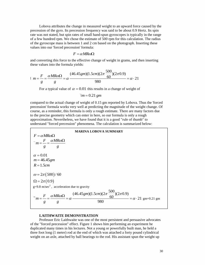
30
Lobova attributes the change in measured weight to an upward force caused by the
precession of the gyro. Its precession frequency was said to be about 0.9 Hertz. Its spin
rate was not stated, but spin rates of small hand-spun gyroscopes is typically in the range
of a few hundred rpm. We chose the estimate of 500 rpm for this calculation. The radius
of the gyroscope mass is between 1 and 2 cm based on the photograph. Inserting these
values into our 'forced precession' formula:
F MR
and converting this force to the effective change of weight in grams, and then inserting
these values into the formula yields:
500(46.45 )(1.5 )(2 )(2 0.9)
60 21980
gm cmF MR
mg g
For a typical value of 0.01 this results in a change of weight of
0.21m gm
compared to the actual change of weight of 0.15 gm reported by Lobova. Thus the 'forced
precession' formula works very well at predicting the magnitude of the weight change. Of
course, as a reminder, this formula is only a rough estimate. There are many factors due
to the precise geometry which can enter in here, so our formula is only a rough
approximation. Nevertheless, we have found that it is a good "rule of thumb" to
understand "forced precession" phenomena. The calculation is summarized below:
LAITHWAITE DEMONSTRATION
Professor Eric Laithwaite was one of the most persistent and persuasive advocates
of the "forced precession" effect. Figure 1 shows him performing an experiment he
duplicated many times in his lectures. Not a young or powerfully built man, he held a
three foot long (1 meter) rod at the end of which was attached a forty pound cylindrical
weight on an axle, attached by ball bearings to the rod. His assistant spun the weight up
MARINA LOBOVA SUMMARY
F MR
F MRm
g g
0.01
46.45m gm
1.5R cm
2 500 / 60
2 0.9
g=9.8 m/sec2 , acceleration due to gravity
500(46.45 )(1.5 )(2 )(2 0.9)
60 21980
gm cmF MR
mg g
gm=0.21 gm
19 kg is enough to make the weight rise on its own
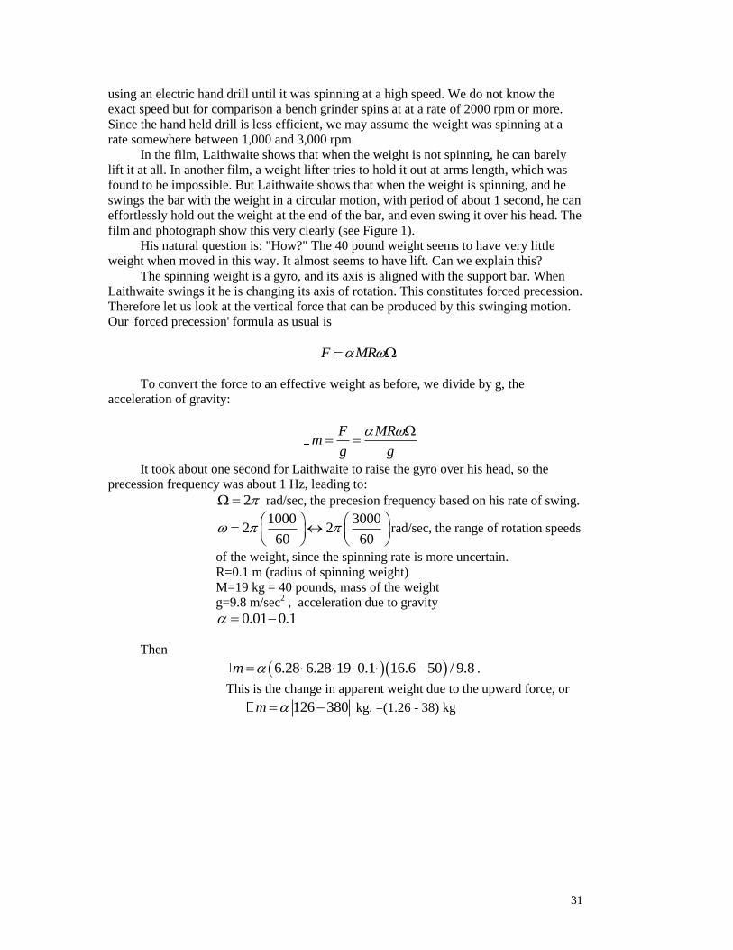
31
using an electric hand drill until it was spinning at a high speed. We do not know the
exact speed but for comparison a bench grinder spins at at a rate of 2000 rpm or more.
Since the hand held drill is less efficient, we may assume the weight was spinning at a
rate somewhere between 1,000 and 3,000 rpm.
In the film, Laithwaite shows that when the weight is not spinning, he can barely
lift it at all. In another film, a weight lifter tries to hold it out at arms length, which was
found to be impossible. But Laithwaite shows that when the weight is spinning, and he
swings the bar with the weight in a circular motion, with period of about 1 second, he can
effortlessly hold out the weight at the end of the bar, and even swing it over his head. The
film and photograph show this very clearly (see Figure 1).
His natural question is: "How?" The 40 pound weight seems to have very little
weight when moved in this way. It almost seems to have lift. Can we explain this?
The spinning weight is a gyro, and its axis is aligned with the support bar. When
Laithwaite swings it he is changing its axis of rotation. This constitutes forced precession.
Therefore let us look at the vertical force that can be produced by this swinging motion.
Our 'forced precession' formula as usual is
F MR
To convert the force to an effective weight as before, we divide by g, the
acceleration of gravity:
F MR
mg g
It took about one second for Laithwaite to raise the gyro over his head, so the
precession frequency was about 1 Hz, leading to:
2 rad/sec, the precesion frequency based on his rate of swing.
1000 30002 2
60 60
rad/sec, the range of rotation speeds
of the weight, since the spinning rate is more uncertain.
R=0.1 m (radius of spinning weight)
M=19 kg = 40 pounds, mass of the weight
g=9.8 m/sec2 , acceleration due to gravity
0.01 0.1
Then
6.28 6.28 19 0.1 16.6 50 / 9.8m .
This is the change in apparent weight due to the upward force, or
126 380m kg. =(1.26 - 38) kg

32
This is the change in apparent weight due to the swinging motion. The difference
here is based on the two possible spin speeds, either 1,000 rpm or 3,000 rpm. For =
0.01 this results in a force equivalent to (1.26 - 3.8) kg force, and for 0.1 the
predicted force equivalent is (12.6 - 38) kg force. This is more than sufficient to lift the
19 kg weight into the air, and explains why Laithwaite said that the mass felt virtually
weightless when moved in this way.
SANDY KIDD GYRO
Sandy Kidd is only one of many inventors who has claimed to have built a "forced
precession" gyro. Kidd's device was discussed earlier. It received a patent (#5024112)
and several working models have been built. For example, Figure 6 shows a photograph
of one of Sandy Kidd's gyro devices, which has undergone careful testing and appears to
exhibit "forced precession." The two circular disks on either side spin rapidly and act as
gyroscopes. The levers in the middle act to vary the spin axis of the gyros. From the
Youtube video the entire device can be observed spinning, which is how the gyro axis is
changed. The entire assembly begins to rotate and as it does, it lifts in the vertical
direction (Laithwaite, 2016). Because earlier models do not produce enough lift to
entirely cancel the weight, a counterweight is used in the experiments shown on Youtube.
Nevertheless, the device, which carries a small gasoline engine on board to spin the
gyros, does appear to generate about the same lift as observed in the Youtube
experiments.
PROF. ERIC LAITHWAITE SUMMARY
0.01 0.1
M=19 kg = 40 pounds, mass of the weight
R=0.1 m (radius of spinning weight)
1000 30002 2
60 60
= 2 16.6 50 rad/sec
2 rad/sec
g=9.8 m/sec2 , acceleration due to gravity
126 380m kg. =(1.26 - 38) kg due to range of rpm from 1,000 to 3,000
19 kg is enough to make the weight rise on its own
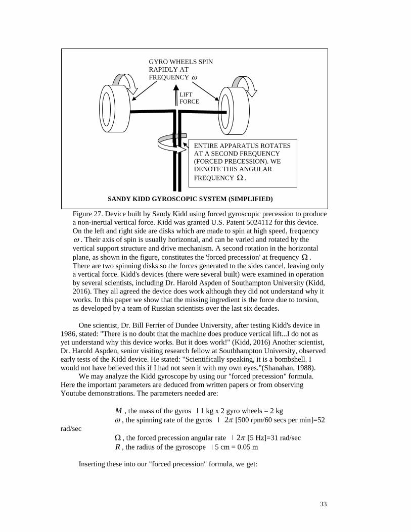
33
Figure 27. Device built by Sandy Kidd using forced gyroscopic precession to produce
a non-inertial vertical force. Kidd was granted U.S. Patent 5024112 for this device.
On the left and right side are disks which are made to spin at high speed, frequency
. Their axis of spin is usually horizontal, and can be varied and rotated by the
vertical support structure and drive mechanism. A second rotation in the horizontal
plane, as shown in the figure, constitutes the 'forced precession' at frequency .
There are two spinning disks so the forces generated to the sides cancel, leaving only
a vertical force. Kidd's devices (there were several built) were examined in operation
by several scientists, including Dr. Harold Aspden of Southampton University (Kidd,
2016). They all agreed the device does work although they did not understand why it
works. In this paper we show that the missing ingredient is the force due to torsion,
as developed by a team of Russian scientists over the last six decades.
One scientist, Dr. Bill Ferrier of Dundee University, after testing Kidd's device in
1986, stated: "There is no doubt that the machine does produce vertical lift...I do not as
yet understand why this device works. But it does work!" (Kidd, 2016) Another scientist,
Dr. Harold Aspden, senior visiting research fellow at Southhampton University, observed
early tests of the Kidd device. He stated: "Scientifically speaking, it is a bombshell. I
would not have believed this if I had not seen it with my own eyes."(Shanahan, 1988).
We may analyze the Kidd gyroscope by using our "forced precession" formula.
Here the important parameters are deduced from written papers or from observing
Youtube demonstrations. The parameters needed are:
M , the mass of the gyros 1 kg x 2 gyro wheels = 2 kg
, the spinning rate of the gyros 2 [500 rpm/60 secs per min]=52
rad/sec
, the forced precession angular rate 2 [5 Hz]=31 rad/sec
R , the radius of the gyroscope 5 cm = 0.05 m
Inserting these into our "forced precession" formula, we get:
GYRO WHEELS SPIN
RAPIDLY AT
FREQUENCY
ENTIRE APPARATUS ROTATES
AT A SECOND FREQUENCY
(FORCED PRECESSION). WE
DENOTE THIS ANGULAR
FREQUENCY .
LIFT
FORCE
SANDY KIDD GYROSCOPIC SYSTEM (SIMPLIFIED)
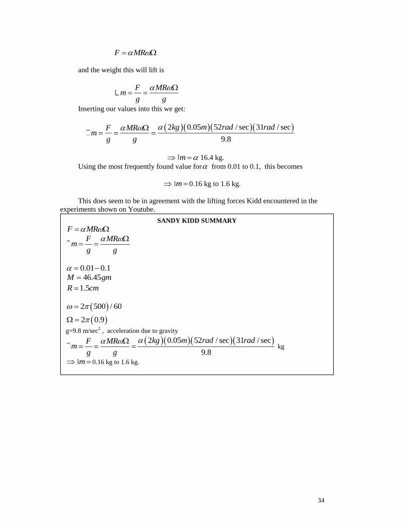
34
F MR
and the weight this will lift is
F MR
mg g
Inserting our values into this we get:
2 0.05 52 / sec 31 / sec
9.8
kg m rad radF MRm
g g
m 16.4 kg.
Using the most frequently found value for from 0.01 to 0.1, this becomes
m 0.16 kg to 1.6 kg.
This does seem to be in agreement with the lifting forces Kidd encountered in the
experiments shown on Youtube.
SANDY KIDD SUMMARY
F MR
F MRm
g g
0.01 0.1
46.45M gm
1.5R cm
2 500 / 60
2 0.9
g=9.8 m/sec2 , acceleration due to gravity
2 0.05 52 / sec 31 / sec
9.8
kg m rad radF MRm
g g
kg
m 0.16 kg to 1.6 kg.
19 kg is enough to make the weight rise on its own

35
VIKTOR SCHAUBERGER
Some of Viktor Schauberger's devices, as shown in Figure 28, were reputed to
generate their own energy and even to levitate, all from a spinning flow of water (Coats,
1996). One of the hallmarks of Schauberger's special pipes is that they resembled
corkscrews, and actually had a second twist in the tubing as well as the corkscrew shape.
This produced a twisting spiral flow which they imparted to water flowing in them. This
double spiral is equivalent to gyroscopic spin PLUS precession, so his special pipes
actually impart the same motion to water that the forced precession gyros do with solid
matter. Figure 29 shows the design of some of these pipes.
One of the amazing qualities of some of Schauberger's pipes is that, when water
flowed through them at a certain speed, it actually increased its speed as it passed through
the pipes. This implies that it picked up energy and increased pressure at a certain
velocity. This was confirmed by Professor Popel, an arch critic of Schauberger, who
conducting careful measurements of the pipes in the expectation that he would show
Schauberger was a fraud. Instead, being an honest and careful researcher, he found that at
a certain speed of about 60 cm per second, the water in some of the pipes actually gained
energy. The pipes exhibited negative friction at that speed.
This is shown in Figure 30 taken from Popel's data, and republished by Callum
Coats (Coats, 1996). The graph shows the data for several water pipes, some straight,
some with a single twist, and some with the more complex "double spiral" invented by
Schauberger. The graph shows the pressure loss at the end of each pipe. For one of
Schauberger's designs, the double spiral, the pressure loss actually goes negative at a flow
speed of 60 cm/sec. This means the water is not losing any energy, and is actually gaining
energy. All the other pipes, especially the conventional straight cylinders, saw the
pressure drop (due to friction) increase with speed as expected.
Such an effect cannot be explained by conventional physics, because it is showing
non-conservation of energy. However, Shipov predicts similar behavior in other cases
when gyros experience changes in angular momentum or spin rates. It is a torsion effect
and arises from a "bending" of the space-time metric. It was seen in Shipov's 4-D gyro
and other examples (Shipov#7).
In Schauberger's case, the data indicate that energy is being created by the flow.
And in fact, when Schauberger used this design of pipe in his larger devices, he was able
to take advantage of this property. They would run at increased speed without external
power.Therefore this datum is not a fluke. The fact that it was measured and reported by
an arch-skeptic of Schauberger's, Professor Popel, adds to the credibility of this
remarkable result.
The question is: how can this behavior be explained? The answer is that it can be
explained if we realized that the effect of the double spiral is to create forced precession
in the water flowing in the pipe. The small scale twist of the pipes caused the water to
rotate as it passed down the pipes. It creates a small, rapidly spinning vortex. This makes
the water column act like a small gyroscope with its axis of spin aligned with the
direction of flow of the water.
Then the larger scale spiral shape of the pipes, the 'corkscrew shape, generates a
secondary spiral motion of the water. This is the 'forced precession' of the spinning water.
The spinning vortices will change their flow direction and their spin axis slightly as they
follow the shape of the corkscrew. This forced precession will generate a force along the
direction of flow, thereby "pushing" on the water and speeding up the flow. It acts against
the frictional force.
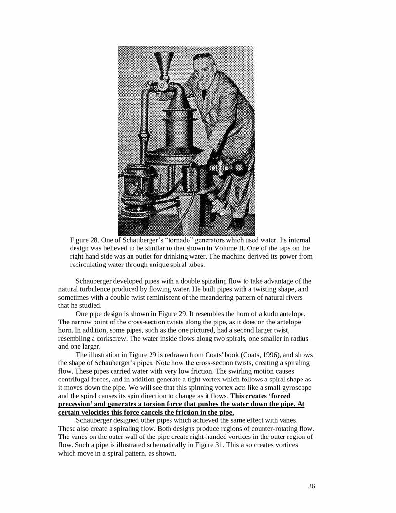
36
Figure 28. One of Schauberger’s “tornado” generators which used water. Its internal
design was believed to be similar to that shown in Volume II. One of the taps on the
right hand side was an outlet for drinking water. The machine derived its power from
recirculating water through unique spiral tubes.
Schauberger developed pipes with a double spiraling flow to take advantage of the
natural turbulence produced by flowing water. He built pipes with a twisting shape, and
sometimes with a double twist reminiscent of the meandering pattern of natural rivers
that he studied.
One pipe design is shown in Figure 29. It resembles the horn of a kudu antelope.
The narrow point of the cross-section twists along the pipe, as it does on the antelope
horn. In addition, some pipes, such as the one pictured, had a second larger twist,
resembling a corkscrew. The water inside flows along two spirals, one smaller in radius
and one larger.
The illustration in Figure 29 is redrawn from Coats' book (Coats, 1996), and shows
the shape of Schauberger’s pipes. Note how the cross-section twists, creating a spiraling
flow. These pipes carried water with very low friction. The swirling motion causes
centrifugal forces, and in addition generate a tight vortex which follows a spiral shape as
it moves down the pipe. We will see that this spinning vortex acts like a small gyroscope
and the spiral causes its spin direction to change as it flows. This creates ‘forced
precession’ and generates a torsion force that pushes the water down the pipe. At
certain velocities this force cancels the friction in the pipe.
Schauberger designed other pipes which achieved the same effect with vanes.
These also create a spiraling flow. Both designs produce regions of counter-rotating flow.
The vanes on the outer wall of the pipe create right-handed vortices in the outer region of
flow. Such a pipe is illustrated schematically in Figure 31. This also creates vortices
which move in a spiral pattern, as shown.
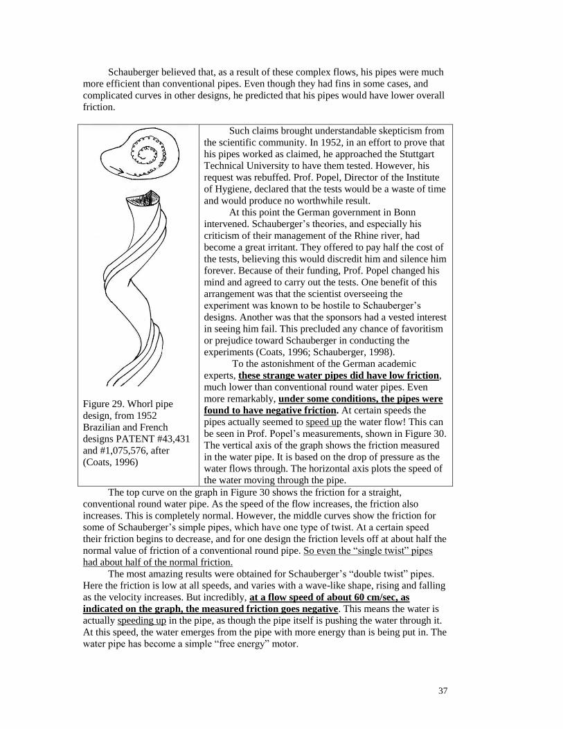
37
Schauberger believed that, as a result of these complex flows, his pipes were much
more efficient than conventional pipes. Even though they had fins in some cases, and
complicated curves in other designs, he predicted that his pipes would have lower overall
friction.
Figure 29. Whorl pipe
design, from 1952
Brazilian and French
designs PATENT #43,431
and #1,075,576, after
(Coats, 1996)
Such claims brought understandable skepticism from
the scientific community. In 1952, in an effort to prove that
his pipes worked as claimed, he approached the Stuttgart
Technical University to have them tested. However, his
request was rebuffed. Prof. Popel, Director of the Institute
of Hygiene, declared that the tests would be a waste of time
and would produce no worthwhile result.
At this point the German government in Bonn
intervened. Schauberger’s theories, and especially his
criticism of their management of the Rhine river, had
become a great irritant. They offered to pay half the cost of
the tests, believing this would discredit him and silence him
forever. Because of their funding, Prof. Popel changed his
mind and agreed to carry out the tests. One benefit of this
arrangement was that the scientist overseeing the
experiment was known to be hostile to Schauberger’s
designs. Another was that the sponsors had a vested interest
in seeing him fail. This precluded any chance of favoritism
or prejudice toward Schauberger in conducting the
experiments (Coats, 1996; Schauberger, 1998).
To the astonishment of the German academic
experts, these strange water pipes did have low friction,
much lower than conventional round water pipes. Even
more remarkably, under some conditions, the pipes were
found to have negative friction. At certain speeds the
pipes actually seemed to speed up the water flow! This can
be seen in Prof. Popel’s measurements, shown in Figure 30.
The vertical axis of the graph shows the friction measured
in the water pipe. It is based on the drop of pressure as the
water flows through. The horizontal axis plots the speed of
the water moving through the pipe.
The top curve on the graph in Figure 30 shows the friction for a straight,
conventional round water pipe. As the speed of the flow increases, the friction also
increases. This is completely normal. However, the middle curves show the friction for
some of Schauberger’s simple pipes, which have one type of twist. At a certain speed
their friction begins to decrease, and for one design the friction levels off at about half the
normal value of friction of a conventional round pipe. So even the “single twist” pipes
had about half of the normal friction.
The most amazing results were obtained for Schauberger’s “double twist” pipes.
Here the friction is low at all speeds, and varies with a wave-like shape, rising and falling
as the velocity increases. But incredibly, at a flow speed of about 60 cm/sec, as
indicated on the graph, the measured friction goes negative. This means the water is
actually speeding up in the pipe, as though the pipe itself is pushing the water through it.
At this speed, the water emerges from the pipe with more energy than is being put in. The
water pipe has become a simple “free energy” motor.

38
Figure 30. Measurements by Professor Popel in Germany. Although an extreme
skeptic about Schauberger’s water pipes, Popel’s measurements proved that they
carried water with much less friction than conventional pipes. Popel even discovered
one flow speed, 60 cm/sec, shown in the graph, at which the friction goes negative.
This means the water actually gains some energy going through the pipe, and should
come out faster! The vertical scale is graduated in centimeters pressure of mercury.
The horizontal scale is the flow speed of the water, in cm/sec. After (Coats, 1996)
This would appear to break two important laws of physics, the Second Law of
Thermodynamics and the Conservation of Energy. And yet the data was carefully taken
by the foremost hydrodynamics expert in Austria, who was quite skeptical of
Schauberger at the time, and had every incentive to find flaws in the design. Instead, he
confirmed that Schauberger’s pipes were truly remarkable in their performance.
There were several versions designed and built (Coats, 1996). They all used similar
principles but with slightly different designs and names. The names of the some of
devices were the “Trout Engine,” the “Repulsator,” the “Repulsine,” and the “Implosion
Motor.” Each of these reportedly exhibited similar unusual behavior: (1) It rotated on its
own, with no external power except to start it. (2) The water became colder, approaching
4 degrees C, as it was continually cycled through. (3) It had very quiet and cheap
operation. (4) As the water cycled through it was claimed to sometimes develop an
antigravity property, beginning to levitate and take on a bluish glow as it was operating.
The motor at the top of the shaft was used to start the process. The generator was
claimed capable of producing up to 50,000 watts of electricity once the system reached
speed and became self-sustaining (Coats, 1996).
As in most of these devices, according to Coats, the problem was
“…not how to start it but how to stop it without damage, due to its high velocity
rotation and the extraordinary repulsive force developed at the end of each nozzle.
For this, it has been suggested that the best way is to cut off the water supply…the
whole machine should be very firmly anchored to the floor to prevent it rising into
the air as a result of the powerful levitational forces generated in the
process.”(Coats, 1996)

39
Decreases of temperature around Schauberger’s devices, together with the claimed
over-unity energy production and apparent decrease of entropy, suggest that its behavior
might be explained if somehow time were running backwards, or if the device were
producing negative entropy. Both of these ideas fly in the face of conventional physics.
However, as we see when torsion is present, effects of this kind are frequently observed
(Swanson, 2011).
Schauberger Analysis
One of the characteristics of Schauberger's pipes is that they are not round. They
have an indentation or vane in the flow that generates a vortex in the water flow. This can
be seen in Figure 29. The pipe is shaped so as to produce a vortex and then guide it along
a spiral “corkscrew” path. The vortex does not flow in a straight line, but moves in a
serpentine or spiral shape. The ridge or groove makes a spiral along the outside of the
pipe, guiding the vortex inside to also trace out a spiral shape. Another pipe design used a
straight pipe but with canted vanes to generate and guide vortices along a similar spiral
pattern. The effect of this unusual flow can be analyzed as follows.
In either case, part of the flow is converted into a vortex which flows inside the
pipe, aligned with the direction of flow. This vortex acts like a small gyroscope with its
spin axis aligned with the flow direction. This is illustrated in Figure 31. The serpentine
path which the vortex takes in some of the Schauberger pipes causes the spin direction of
this vortex to oscillate and causes the small gyros within the vortex to undergo forced
precession. It is this forced precession which gives rise to a forward force accelerating the
flow along the pipe and opposing the force of pipe friction.
To estimate this, let the pipe diameter be D and its radius R. We will approximate
its shape as round even though Schauberger occasionally departs from this. In some
cases, as in Figure S-2 the shape of the pipe is designed to create vortices in the flow.
And in other pipe designs, such as shown in Figure S-3, vanes are used to accomplish
this. The diameter of the vortices so produced must be less than R, and typically are of
the order of R/2 or less. due to the shape of the pipe or size of the vanes. In general we
denote the diameter of this vortex by d, and approximate it as D/4.
Therefore we roughly estimate the diameter of the small vortex to be d:
4
Dd
with a period to make one complete rotation in the flow of
2d
dT
V
and based on the speed downstream of its motion, its frequency of rotation is
2d
d
V
T d
If we consider some small element of this vortex, of thickness dx in the direction
parallel to motion, then this disk-shaped slice of water can be thought of as a small gyro,
spinning about the same axis that the vortex spins around. Thus each element of the
vortex can be treated as a small vortex with angular momentum and spin axis aligned
with the vortex (see Figure 31).

40
If we examine a thin slice of thickness dx of the vortex, where dx is in the along-
track direction of the vortex, this mass is 2
4
ddm dx
where is the density of the fluid (usually water). Since each element of the vortex is
spinning, it has some angular momentum J which is parallel to the flow direction. It acts
like a small gyroscope. Since the vortex is guided by the pipe to move in a corkscrew
pattern, the spin direction or angular momentum of the spinning disk of water changes
direction as it moves along the pipe. This periodic change of its spin direction constitutes
"forced precession."
The period of time for this larger scale motion depends on the wavelength of the
corkscrew motion and the velocity V of the flow. Based on images of Schauberger's
pipes, this length is estimated to be on the order of D to 2 D, where D is the pipe
diameter. The period of time it takes for a volume element of water to go this distance is
2D
DT
V
The resulting cyclic motion constitutes forced precession. The axis of spin of the small
gyros in the vortex flow will undergo a periodic change of direction as they follow the
corkscrew path of the vortex. This is the period of the longer scale motion. It results in a
frequency for the 'forced precession' of :
2
D
V
T D
Now we can estimate the force on this small volume element of water based on the
forced precession formula.
dF dm R
and substituting the values we have for these parameters:
2
4
d V VdF dm R dx R
d D
which simplifies to
2
16dF dx RV
or
2
16SCHAU
dFRV
dx
This force results from Schauberger’s unique spiral shaped pipes. It is in the
forward direction and is produced by the “forced precession” of the water in the vortex.
It pushes the water down the pipes. It opposes the force of friction. This may be
converted to pressure by dividing by the area of the pipe, which is 2 / 4D :
2
8SCHAU
dP V
dx D
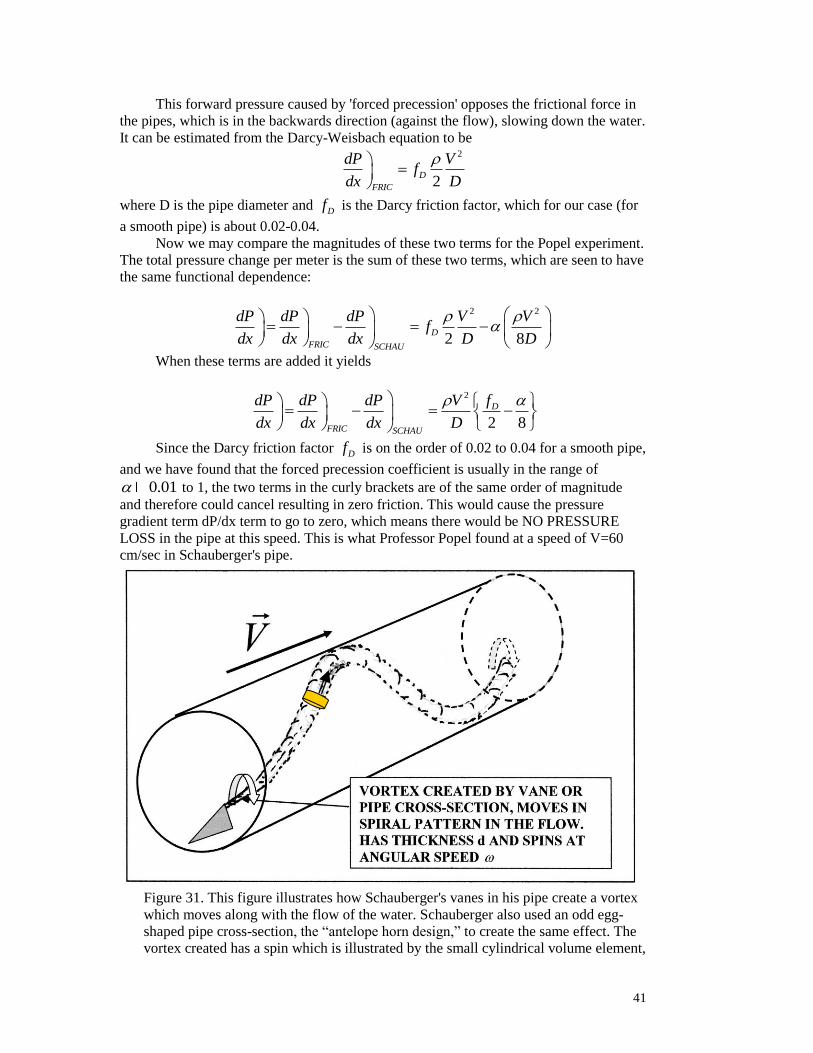
41
This forward pressure caused by 'forced precession' opposes the frictional force in
the pipes, which is in the backwards direction (against the flow), slowing down the water.
It can be estimated from the Darcy-Weisbach equation to be
2
2D
FRIC
dP Vf
dx D
where D is the pipe diameter and Df is the Darcy friction factor, which for our case (for
a smooth pipe) is about 0.02-0.04.
Now we may compare the magnitudes of these two terms for the Popel experiment.
The total pressure change per meter is the sum of these two terms, which are seen to have
the same functional dependence:
2 2
2 8D
FRIC SCHAU
dP dP dP V Vf
dx dx dx D D
When these terms are added it yields
2
2 8
D
FRIC SCHAU
fdP dP dP V
dx dx dx D
Since the Darcy friction factor Df is on the order of 0.02 to 0.04 for a smooth pipe,
and we have found that the forced precession coefficient is usually in the range of
0.01 to 1, the two terms in the curly brackets are of the same order of magnitude
and therefore could cancel resulting in zero friction. This would cause the pressure
gradient term dP/dx term to go to zero, which means there would be NO PRESSURE
LOSS in the pipe at this speed. This is what Professor Popel found at a speed of V=60
cm/sec in Schauberger's pipe.
Figure 31. This figure illustrates how Schauberger's vanes in his pipe create a vortex
which moves along with the flow of the water. Schauberger also used an odd egg-
shaped pipe cross-section, the “antelope horn design,” to create the same effect. The
vortex created has a spin which is illustrated by the small cylindrical volume element,

42
which rotates and acts like a tiny gyro. Its spin axis is aligned with the velocity of the
flow. If the vortex is made to undergo a spiraling motion, the spin of the tiny gyro
will follow this spiral motion, too. This constitutes “force precession,” because the
spin axis of the gyro is made to vary over time as the vortex follows a spiral motion.
In fact, the terms are so close in value that it is easy to see how the “forced
precession” term from the spiral vortex could become greater, resulting in a net forward
pressure as Popel encountered at 60 cm/sec.
This is as well as we can do with this crude estimate. The key here is that the flow
speed is of the right value that a vortex is created which follows a serpentine path in the
pipe, and that it matches the pipe dimensions so its spiral shape is stable.
In the Popel experiment this occurred when the flow velocity was 60 cm per second
for the largest effect. The conclusion of this analysis is that, within the approximations
we have made, there can be a 'forced precession' term from the spiraling vortex flow
which produces a force which can be about the right magnitude to oppose the friction
force. More accurate analysis would require numerical simulation of the flow.
The important point here is that the phenomenon of 'forced precession' yields a
possible answer to a very long standing puzzle: how did Schauberger's pipes produce the
effect that was observed? Based on the testimony of many scientists and observers
involved, there certainly seemed to be an effect. Now we may have the answer to this
puzzle.
VIKTOR SCHAUBERGER SUMMARY
F MR
F MRm
g g
D=2.7 cm
0.01 0.1
0.02Df
R=D/2
4
Dd approx. diameter of vortex
2d
d
V
T d
2
D
V
T D
2
4
d V VdF dm R dx R
d D
(Schauberger in flow direction)
2
16dF dx RV
2 2
2 8D
FRIC SCHAU
dP dP dP V Vf
dx dx dx D D
2 2 0.02 0.01 0.10
2 8 2 8
D
FRIC SCHAU
fdP dP dP V V
dx dx dx D D
19 kg is enough to make the weight rise on its own
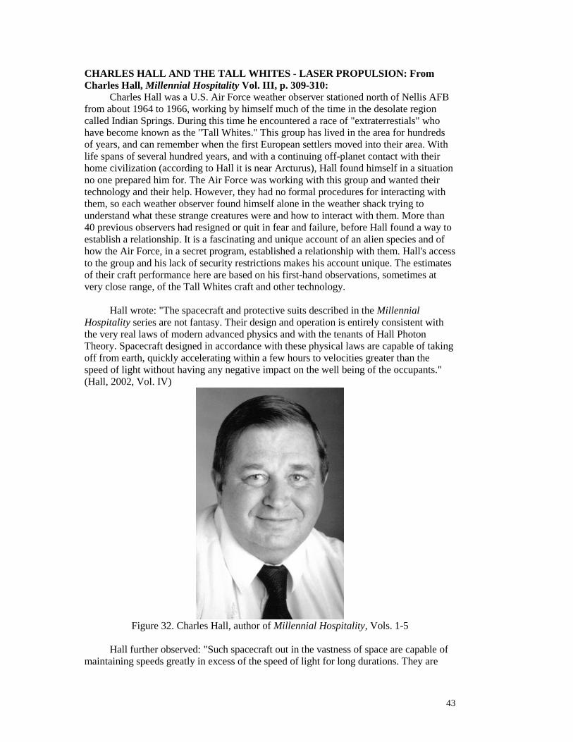
43
CHARLES HALL AND THE TALL WHITES - LASER PROPULSION: From
Charles Hall, Millennial Hospitality Vol. III, p. 309-310:
Charles Hall was a U.S. Air Force weather observer stationed north of Nellis AFB
from about 1964 to 1966, working by himself much of the time in the desolate region
called Indian Springs. During this time he encountered a race of "extraterrestials" who
have become known as the "Tall Whites." This group has lived in the area for hundreds
of years, and can remember when the first European settlers moved into their area. With
life spans of several hundred years, and with a continuing off-planet contact with their
home civilization (according to Hall it is near Arcturus), Hall found himself in a situation
no one prepared him for. The Air Force was working with this group and wanted their
technology and their help. However, they had no formal procedures for interacting with
them, so each weather observer found himself alone in the weather shack trying to
understand what these strange creatures were and how to interact with them. More than
40 previous observers had resigned or quit in fear and failure, before Hall found a way to
establish a relationship. It is a fascinating and unique account of an alien species and of
how the Air Force, in a secret program, established a relationship with them. Hall's access
to the group and his lack of security restrictions makes his account unique. The estimates
of their craft performance here are based on his first-hand observations, sometimes at
very close range, of the Tall Whites craft and other technology.
Hall wrote: "The spacecraft and protective suits described in the Millennial
Hospitality series are not fantasy. Their design and operation is entirely consistent with
the very real laws of modern advanced physics and with the tenants of Hall Photon
Theory. Spacecraft designed in accordance with these physical laws are capable of taking
off from earth, quickly accelerating within a few hours to velocities greater than the
speed of light without having any negative impact on the well being of the occupants."
(Hall, 2002, Vol. IV)
Figure 32. Charles Hall, author of Millennial Hospitality, Vols. 1-5
Hall further observed: "Such spacecraft out in the vastness of space are capable of
maintaining speeds greatly in excess of the speed of light for long durations. They are
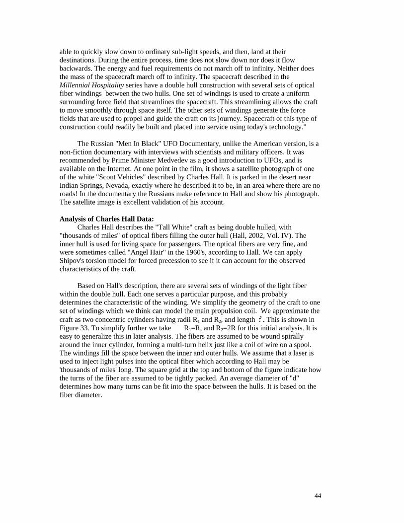
44
able to quickly slow down to ordinary sub-light speeds, and then, land at their
destinations. During the entire process, time does not slow down nor does it flow
backwards. The energy and fuel requirements do not march off to infinity. Neither does
the mass of the spacecraft march off to infinity. The spacecraft described in the
Millennial Hospitality series have a double hull construction with several sets of optical
fiber windings between the two hulls. One set of windings is used to create a uniform
surrounding force field that streamlines the spacecraft. This streamlining allows the craft
to move smoothly through space itself. The other sets of windings generate the force
fields that are used to propel and guide the craft on its journey. Spacecraft of this type of
construction could readily be built and placed into service using today's technology."
The Russian "Men In Black" UFO Documentary, unlike the American version, is a
non-fiction documentary with interviews with scientists and military officers. It was
recommended by Prime Minister Medvedev as a good introduction to UFOs, and is
available on the Internet. At one point in the film, it shows a satellite photograph of one
of the white "Scout Vehicles" described by Charles Hall. It is parked in the desert near
Indian Springs, Nevada, exactly where he described it to be, in an area where there are no
roads! In the documentary the Russians make reference to Hall and show his photograph.
The satellite image is excellent validation of his account.
Analysis of Charles Hall Data:
Charles Hall describes the "Tall White" craft as being double hulled, with
"thousands of miles" of optical fibers filling the outer hull (Hall, 2002, Vol. IV). The
inner hull is used for living space for passengers. The optical fibers are very fine, and
were sometimes called "Angel Hair" in the 1960's, according to Hall. We can apply
Shipov's torsion model for forced precession to see if it can account for the observed
characteristics of the craft.
Based on Hall's description, there are several sets of windings of the light fiber
within the double hull. Each one serves a particular purpose, and this probably
determines the characteristic of the winding. We simplify the geometry of the craft to one
set of windings which we think can model the main propulsion coil. We approximate the
craft as two concentric cylinders having radii R1 and R2, and length . This is shown in
Figure 33. To simplify further we take R1=R, and R2=2R for this initial analysis. It is
easy to generalize this in later analysis. The fibers are assumed to be wound spirally
around the inner cylinder, forming a multi-turn helix just like a coil of wire on a spool.
The windings fill the space between the inner and outer hulls. We assume that a laser is
used to inject light pulses into the optical fiber which according to Hall may be
'thousands of miles' long. The square grid at the top and bottom of the figure indicate how
the turns of the fiber are assumed to be tightly packed. An average diameter of "d"
determines how many turns can be fit into the space between the hulls. It is based on the
fiber diameter.

45
Figure 33. Arrangement of fiber optics in the double hull of the vehicles.
We do not know initially the diameter of the fiber so we call this dimension "d" and
approximate it as a square to estimate the packing density of fibers. We assume the fiber
is wound helically in a plane perpendicular to the long axis of the cylinder, forming a
spiral just like wire in a spool. This is indicted in Figure 33 and 34.
The force to accelerate the craft, we assume, comes from ‘forced precession,’ in
this case due to circularly polarized photons traveling in the optical fiber. Optical fibers
can be manufactured to carry light pulses which propagate as circularly polarized single
mode pulses. These propagate along the light fiber with angular momentum parallel to
the direction of motion, either in the forward or backward directly. This is illustrated in
Figure 34.
These light pulses (quanta) comprise in essence little gyroscopes made up of
energy, spinning around their axis which is parallel to the direction of motion. The
"mass" of each gyroscope is made up of the energy in one quantum of light,
qE h
Here is the frequency of the light, and h is "h-bar" or Planck's constant over 2 . The
angular momentum or the spin of each little quantum gyro is just h. As the quantum
propagates around the circular winding of the hull, the spin of each gyro is forced to
rotate or precess by 360 degrees, so the coil winding causes a "forced precession" of the
angular momentum in each light quantum (see Figure 35).
R1
R2 FIBER
OPTIC
WINDINGS
ILLUSTRATION OF ONE SET OF FIBER OPTIC WINDINGS BETWEEN INNER
AND OUTER HULL OF HYPOTHETICAL "TALL WHITE" CRAFT
LASER
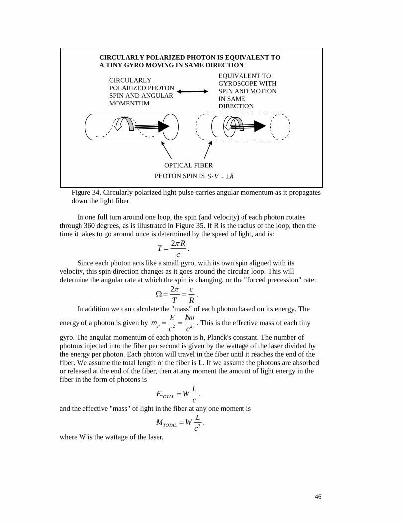
46
Figure 34. Circularly polarized light pulse carries angular momentum as it propagates
down the light fiber.
In one full turn around one loop, the spin (and velocity) of each photon rotates
through 360 degrees, as is illustrated in Figure 35. If R is the radius of the loop, then the
time it takes to go around once is determined by the speed of light, and is:
2 R
Tc
.
Since each photon acts like a small gyro, with its own spin aligned with its
velocity, this spin direction changes as it goes around the circular loop. This will
determine the angular rate at which the spin is changing, or the "forced precession" rate:
2 c
T R
.
In addition we can calculate the "mass" of each photon based on its energy. The
energy of a photon is given by 2 2p
E hm
c c
. This is the effective mass of each tiny
gyro. The angular momentum of each photon is h, Planck's constant. The number of
photons injected into the fiber per second is given by the wattage of the laser divided by
the energy per photon. Each photon will travel in the fiber until it reaches the end of the
fiber. We assume the total length of the fiber is L. If we assume the photons are absorbed
or released at the end of the fiber, then at any moment the amount of light energy in the
fiber in the form of photons is
TOTAL
LE W
c ,
and the effective "mass" of light in the fiber at any one moment is
3TOTAL
LM W
c .
where W is the wattage of the laser.
CIRCULARLY
POLARIZED PHOTON
SPIN AND ANGULAR
MOMENTUM
EQUIVALENT TO
GYROSCOPE WITH
SPIN AND MOTION
IN SAME
DIRECTION
CIRCULARLY POLARIZED PHOTON IS EQUIVALENT TO
A TINY GYRO MOVING IN SAME DIRECTION
OPTICAL FIBER
PHOTON SPIN IS S V h

47
Figure 35. Each fiber optic winding causes a precession of the light pulses.
Another way of saying this is that the number of photons circling the fiber coil at
any moment is
2
TOTALPHOTONS
M c WLN
h h c
The total length L of fiber in the hull is based on the number of turns in the fiber coil,
which is approximately
2
2
3 RL
d
Here R is the radius of the space between the hulls as well as the radius of the inner hull,
and is the length of the hull. We can insert this into the formula above for the effective
mass of the light traveling around the coils at any one moment:
2
3 2
3TOTAL
RM W
c d
Now we can compute the thrust of the propulsion system based on the forced
precession formula we derived earlier, to compute the total force and acceleration of the
craft. The "forced precession" formula based on Shipov's calculations and numerous
other cases, is
' ' ' 'F M R
where we have added a prime to each symbol to distinguish them from the symbols used
here for our specific case. Based on the preceding results, then
THE SPINS
ROTATE AS THE
PHOTONS TRAVEL
AROUND THE
PATH. THIS
DEFINES THE
FORCED
PRECESSION
FREQUENCY
c
R
AS PHOTONS GO
THROUGH THE
WINDINGS THEY ARE
FORCED TO CHANGE
DIRECTION AS THEY
FOLLOW THE FIBER.
THIS CAUSES THEIR
"SPIN" AND ANGULAR
MOMENTUM TO
CHANGE DIRECTION AS
THEY GO AROUND.
THIS IS FORCED
PRECESSION.
R
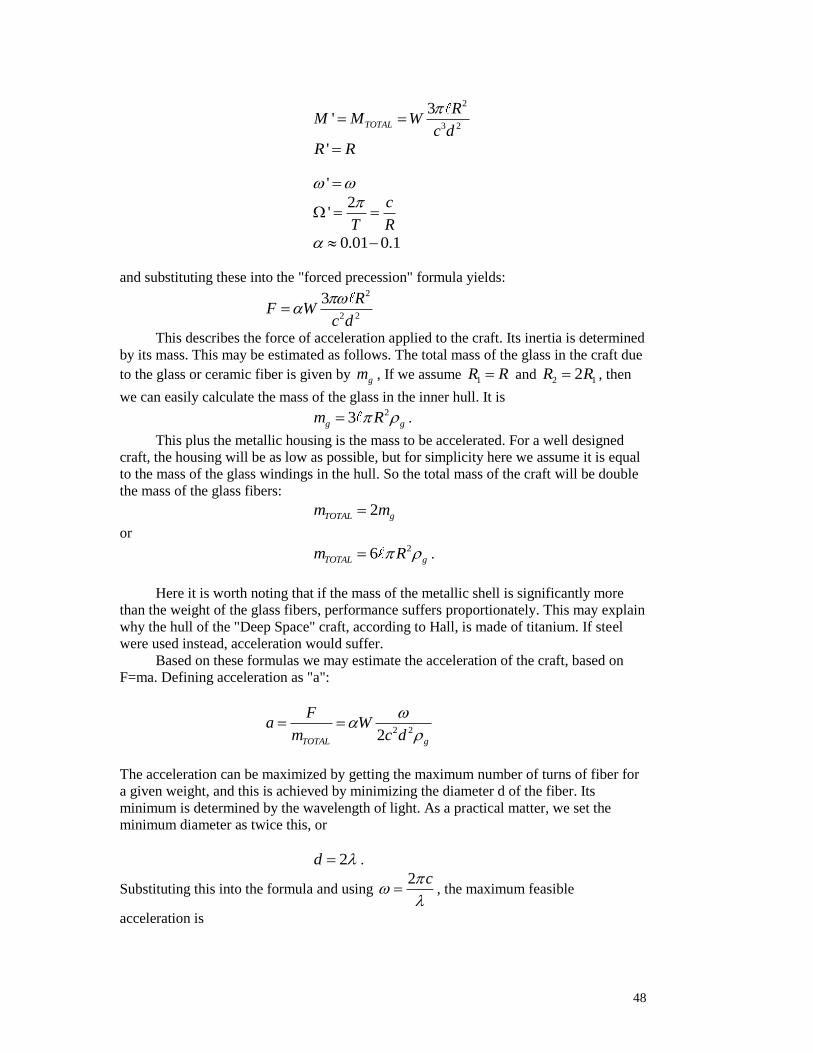
48
2
3 2
3' TOTAL
RM M W
c d
'R R
'
2
'c
T R
0.01 0.1
and substituting these into the "forced precession" formula yields:
2
2 2
3 RF W
c d
This describes the force of acceleration applied to the craft. Its inertia is determined
by its mass. This may be estimated as follows. The total mass of the glass in the craft due
to the glass or ceramic fiber is given by gm , If we assume 1R R and 2 12R R , then
we can easily calculate the mass of the glass in the inner hull. It is
23g gm R .
This plus the metallic housing is the mass to be accelerated. For a well designed
craft, the housing will be as low as possible, but for simplicity here we assume it is equal
to the mass of the glass windings in the hull. So the total mass of the craft will be double
the mass of the glass fibers:
2TOTAL gm m
or
26TOTAL gm R .
Here it is worth noting that if the mass of the metallic shell is significantly more
than the weight of the glass fibers, performance suffers proportionately. This may explain
why the hull of the "Deep Space" craft, according to Hall, is made of titanium. If steel
were used instead, acceleration would suffer.
Based on these formulas we may estimate the acceleration of the craft, based on
F=ma. Defining acceleration as "a":
2 22TOTAL g
Fa W
m c d
The acceleration can be maximized by getting the maximum number of turns of fiber for
a given weight, and this is achieved by minimizing the diameter d of the fiber. Its
minimum is determined by the wavelength of light. As a practical matter, we set the
minimum diameter as twice this, or
2d .
Substituting this into the formula and using 2 c
, the maximum feasible
acceleration is
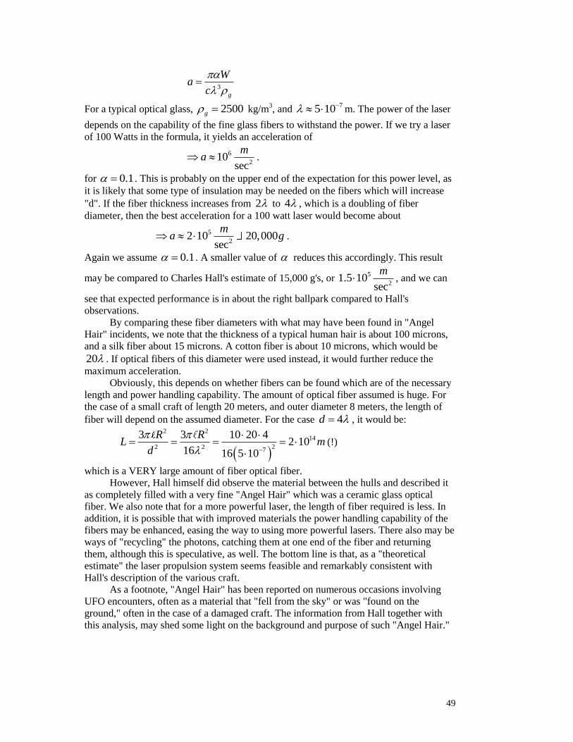
49
3
g
Wa
c
For a typical optical glass, 2500g kg/m3, and
75 10 m. The power of the laser
depends on the capability of the fine glass fibers to withstand the power. If we try a laser
of 100 Watts in the formula, it yields an acceleration of
6
210
sec
ma .
for 0.1 . This is probably on the upper end of the expectation for this power level, as
it is likely that some type of insulation may be needed on the fibers which will increase
"d". If the fiber thickness increases from 2 to 4 , which is a doubling of fiber
diameter, then the best acceleration for a 100 watt laser would become about
5
22 10 20,000
sec
ma g .
Again we assume 0.1 . A smaller value of reduces this accordingly. This result
may be compared to Charles Hall's estimate of 15,000 g's, or 5
21.5 10
sec
m , and we can
see that expected performance is in about the right ballpark compared to Hall's
observations.
By comparing these fiber diameters with what may have been found in "Angel
Hair" incidents, we note that the thickness of a typical human hair is about 100 microns,
and a silk fiber about 15 microns. A cotton fiber is about 10 microns, which would be
20 . If optical fibers of this diameter were used instead, it would further reduce the
maximum acceleration.
Obviously, this depends on whether fibers can be found which are of the necessary
length and power handling capability. The amount of optical fiber assumed is huge. For
the case of a small craft of length 20 meters, and outer diameter 8 meters, the length of
fiber will depend on the assumed diameter. For the case 4d , it would be:
2 214
22 2 7
3 3 10 20 42 10
16 16 5 10
R RL m
d
(!)
which is a VERY large amount of fiber optical fiber.
However, Hall himself did observe the material between the hulls and described it
as completely filled with a very fine "Angel Hair" which was a ceramic glass optical
fiber. We also note that for a more powerful laser, the length of fiber required is less. In
addition, it is possible that with improved materials the power handling capability of the
fibers may be enhanced, easing the way to using more powerful lasers. There also may be
ways of "recycling" the photons, catching them at one end of the fiber and returning
them, although this is speculative, as well. The bottom line is that, as a "theoretical
estimate" the laser propulsion system seems feasible and remarkably consistent with
Hall's description of the various craft.
As a footnote, "Angel Hair" has been reported on numerous occasions involving
UFO encounters, often as a material that "fell from the sky" or was "found on the
ground," often in the case of a damaged craft. The information from Hall together with
this analysis, may shed some light on the background and purpose of such "Angel Hair."

50
CHARLES HALL SUMMARY
qE h
2 c
T R
(TIME FOR ONE LOOP) = PRECESSION
2 2p
E hm
c c
=’MASS’ FOR ONE PHOTON=SMALL GYRO
TOTAL
LE W
c TOTAL ENERGY IN FIBER AT ONE TIME
3TOTAL
LM W
c = ‘MASS OF LIGHT’ IN FIBER AT ONE MOMENT
2
TOTALPHOTONS
M c WLN
h h c
2
2
3 RL
d
= LENGTH OF FIBER
2
3 2
3TOTAL
RM W
c d
=MASS TRAPPED IN FIBER AT ONE MOMENT
' ' ' 'F M R =FORCE
0.01 0.1 2
2 2
3 RF W
c d
26TOTAL gm R =TOTAL MASS OF CRAFT (50% IS FIBER)
2 22TOTAL g
Fa W
m c d
=ACCELERATION
3
g
Wa
c
=MAXIMUM FEASIBLE ACCELERATION
5
22 10 20,000
sec
ma g ACCELERATION FOR 0.1
51
References
Many of Shipov's papers, including the ones referenced here, can be found at
www.shipov.com
Adamenko, Victor G., “The Problem of Time and Psi,” preprint (1989)
Alcubierre, M., “The Warp Drive: Hyper-fast Travel Within General Relativity,”
Classical and Quantum Gravity, Vol 11, pp. L73-L77 (1994)
Alcubierre, M., in Classical Quantum Gravity, 11, L73 (1994)
Akimov, A. E., "Heuristic Discussion of Search for New Long Range Actions, The EGS
Concepts," M.: CISE VENT, (1991)
Chernobrov, Vadim A., New Energy Technologies, p 52, July-August (2001)
Coats, Callum, Living Energies, Gateway Books, Bath, UK (1996)
Davis, Ulysses Jr., U S Patent US 2001/0032522 A1, "Vectored Inertial Drive Wobble
Drive," (2001)
Farrell, Joseph.P., The S.S. Brotherhood of the Bell, Adventures Unlimited Press (2006)
Filatov, N.V., “Study of Collision of Bodies with Large Kinetic Momentums: the letter of
N. Filatov to V. Chicherin 08.07. (1969)
Firmage, Joseph, US Patent US 20110125840 A1, "Method and Apparatus for an Inertial
Drive." (2011)
Frolov, Alexander, “Some Experimental News,” New Energy Technologies, Issue # 6,
November-December (2002)
Gamble, Mike, "State of the Art Inertial Linear Propulsion," Seventh Conference on
Future Energy (COFE), Albuquerque, N, July 29-August 1 (2015)
Hall, Charles James, Millennial Hospitality, Vols. 1-4, (2002)
Jadczyk, Arkadiusz, "Comments on Chapter 5 of G.I. Shipov's 'A Theory of Physical
Vacuum'. Part II", Quantum Future Group, Inc., [email protected] (Jadczyk,
Jadczyk#1)
Kidd, Sandy, (2014)https://www.youtube.com/watch?v=OL_Gasok8xw
Kidd, Sandy (2016), "Sandy Kidd, Gyroscopic Propulsion," http://newilluminati.blog-
city.com/antigravity_machine.htm; http://www.gyroscopes.org/propulsion.asp;
www.rexresearch.com (2016)
Korotaev, S. M., “Logic of Causal Mechanics,” in Levich (1996).
Kozyrev, N. A., “Possibility of Experimental Study of the Properties of Time,” JPRS:
45238, translation, U.S. Department of Commerce, from Russian, Pulkovo, O
VOZMOZHNOSTI EKSPERIMENTAL’NOGO ISSLEDOVANIYA SVOYSTV
VREMENI, September, pp. 1-49 (1967)
52
Kozyrev, N. A., “Time as a Physical Phenomenon,” in Modelirovaniye i
Prognozirovaniye v Biologii (Modeling and Forecasting in Bioecology), Riga, pp. 59-72
[in Russian] (1982)
Kozyrev, N. A., and Nasonov, V.V., in Astronomy and Celestial Mechanics [in Russian],
Moscow, Leningrad, pp. 168-179 (1978)
Kozyrev, N. A., and Nasonov, V.V., in Manifestations of Cosmic Factors on Earth and in
the Stars [in Russian], Moscow-Leningrad, 1980, pp. 76-84 and pp. 85-93 (1980),
Kozyrev, N. A., in Physical Aspects of Modern Astronomy [in Russian], Moscow-
Leningrad (1985), pp. 82-89 (1985)
Kozyrev, N.A. and Nasonov, V., “A New Method of the Detemination of
Trigonometrical Parallaxes Based on Measurement of a Difference Between True and
Apparent Star Positions,” Academy of Sciences of the USSR, Institute for Theoretical
Astronomy, in Astronomy and Celestial Mechanics, Series: Problems of Study of the
Universe, 7, Moscow-Leningrad (1978)
Kozyrev, N.A. and Nasonov, V., “On Some Properties of Time Detected with the Help of
Astronomical Observations,” Academy of Sciences of the USSR, Institute for Theoretical
Astronomy, in Some Cosmic Factors Evinced at Earth and Stars, Series: Problems of
Study of the Universe,” 9, Moscow-Leningrad (1980)
Kozyrev, N.A., “Causal or Nonsymmetric Mechanics in a Linear Approximation,”
Pulkovo (1958)
Kozyrev, N.A., “The Origin of Stellar Energy on the Basis of the Analysis of
Observational Data,” Academy of Sciences of Armenia, Journal of Astrophysics, Vol. 12,
No. 2, Erevan (1976)
Kozyrev, N.A., in Flare Stars [in Russian], Erevan (1977)
Kozyrev, N.A., Izbrannyye Trudy ("Selected Works") Leningrad State University (LGU),
[in Russian] (1991)
Laithwaite, (2015) Eric, https://www.youtube.com/watch?v=JDUNV5TJDYI,
https://www.youtube.com/watch?v=BeO91URF7dM,
https://www.youtube.com/watch?v=dy6hLZ02naM, and
https://www.youtube.com/watch?v=MHIAJ7vySC8 are all relevant.
Lavrentiev, M.M. (Academician), Eganova, I.A., Lutset, M.K., and Fominykh, S.F.,
“Remote Effect of Stars on a Resistor,” Sov. Phys. Dokl. Vol. 35 (9), September 1990
(translated from Dokl. Akad.Nauk SSSR, 314, 352-355, September 1990)
Lavrentiev, M.M. (Academician), Gusev, V.A., Eganova, I.A., Lutset, M.K., and
Fominykh, S.F., “Detection of the True Position of the Sun,” Sov. Phys. Dokl. Vol.
35(11), November 1990 (translated from Dokl. Akad.Nauk SSSR, 315, 368-370,
November 1990)
Lavrentiev, M.M. (Academician), Eganova, I.A., Lutset, M. K., and Fominykh, S.F.,
“Detection of the Reaction of Matter to an External Irreversible Process,” Sov. Phys.
Dokl. Vol. 36(3), March 1991 (translated from Dokl. Akad.Nauk SSSR, 3317, 635-635,
March 1991)
Lavrentiev, M.M. (Academician), Eganova, I.A., Medvedev, V.G., Oleinik, V.K., and
Fominykh, S.F., “Scanning the Celestial Sphere with a Kozyrev Detector,” Sov. Phys.

53
Dokl. Vol. 37(4), April 1992 (translated from Dokl. Akad.Nauk SSSR, 323, 649-652,
April (1992)
Levich, A. P., “A Substantial Interpretation of N.A. Kozyrev’s Conception of Time,” pp.
1-42, in On the Way to Understanding the time Phenomenon, World Scientific, Singapore
(1996)
Lobova, Marina, "Forbidden Science," (Shipov#8), http://www.shipov.com/science, 21
January (2013)
Lunev, V.I., Exploratory Experimental Researchers in the Field of Spin-Torsion
Interactions, under the auspices of The Russian Federal Ministry of Science and
Technical Policy, The State Committee of the Russian Federation on Higher Education,
and Tomsk Polytechnical University, published by the Siberian-Scientific Research
Center for the Study of Anomalous Phenomena in the Environment (1995)
Manning, Jeane, "Space, Propulsion and Energy Sciences International Forum- A
Journalisats Notes," Infinite Energy, Issue 103, May/June (2012) In this article Manning
states: "Boeing engineer Michael Gamble revealed that the aerospace corporation he
works for has for years been using the inertial propulsion of forced-precessed gyroscopes
to move satellitesaround in orbit electrically, without firing up any rockets.He said that
news is old enough that he can freely mention it without disclosure problems."
Nachalov, Yu. V. and A.N.Sokolov, “Experimental Investigtion of New Long Range
Actions – Analytical Review,” http://amasci.com/freenrg/tors/doc17.html (2004)
Nachalov, Yu. V., “Theoretical Basics of Experimental Phenomena,
http://www.amasci.com/freenrg/tors/tors3.html (2003)
Neff, Rupert Theodore, US Patent US 2003/0234318 A1, "Unbalanced Gyroscopic
Apparatus for Producing Unidirectional Thrust," (2003)
Ostrander, Sheila and Schroeder, Lynn, Psychic Discoveries Behind the Iron Curtain,
Bantam Books, New York (1970)
Panov, Vyacheslav F.; Kichigin, Vladimir I.; Khaldeev, Gennady V.; Klyuev, Andrei V.;
Testov, Boris V.; Yushkova, Tatyana A.; and Yushkov, Vladimir V., “Torsion Fields and
Experiments,” Journal of New Energy, Vol. 2, Nos. 3-4, Fall-Winter (1997)
Reich, Wilhelm, M.D., CORE (Cosmic Orgone Engineering), Contents-The OROP
Desert, July 1954, Orgone Institute, Rangeley, Maine (1954)
Reich, Wilhelm, M.D., The Bibilography of Orgonomy, The Wilhelm Reich Foundation,
Organon, (www.wilhelmreichmuseum.org/biography.html), Rangeley Maine (1953)
Reich, Wilhelm, M.D., The Oranur Experiment, First Report (1947-1951), The Wilhelm
Reich Foundation, Organon, Rangeley Maine (1951)
Von Reichenbach, Karl Baron, Physico-Physiological Researches on the Dynamics of
Magnetism, Electricity, Heat, Light, Crystallization, and Chemism, in their Relations to
the Vital Force, translated by H. John Ashburner, published by H. Bailliere, London
(1851)
Von Reichenbach, Karl Baron, Researches on Magnetism, Electricity, Heat, Light,
Crystallization, and Chemical Attraction in their Relations to The Vital Force, Parts I and
II, Trans. by William Gregory: Taylor, Walton and Maberly, Publishers, London (1850)
54
Von Reichenbach, Karl Baron, The Odic Force - Reichenbach’s Letters on Od and
Magnetism, translated by F.D.O’Byrne, Hutchinson and Company (1926) from original
in (1852)
Schauberger, Viktor, "The Water Wizard-The Extraordinary Properties of Natural
Water", ed. by Callum Coats, Gateway Books, Bath, UK (1998)
Shakhparonov, I. M., “Kozyrev-Dirac Emanation: Methods of Detecting and Interaction
with Matter,” Journal of New Energy, Vol. 2, No. 3-4 (1998)
Shakhparonov, I.M., Grin, S.A., Tsimbalaev, S.R., Kreindel, L.N., Kocheshkova, V.N.,
Podlesny, A.I., and Gelfand, S. Yu, “Effect of Magnetic Blow Wave Field on Wine
Systems,” New Energy Technologies, #2(5) (2002)
Shakhparonov, Ivan M, “Interaction of Matter and Methods of Detecting,” New Energy
Technologies, Vol. 1, p 275-280 (2001)
Shakhparonov, Ivan M., “Interaction Between Kozyrev-Dirac Radiation and
Radionuclides,” Journal of New Energy, Vol. 3, No. 4, Spring (1999)
Shanahan, Michael, "Gyroscopic Propulsion-Garden shed genius heads for the stars",
Sunday Express, London, Oct. 23, 1988, http://www.amazon.co.uk/Beyond-2001-Laws-
Physics-Revolutionized/dp/028399925X (1988)
Shipov, Gennady, A Theory of the Physical Vacuum, Russian Academy of Natural
Sciences, Moskow (in English) (1998)
Shipov, Gennady, Youtube lecture: https://www.youtube.com/watch?v=-gnrl-VCcqg
Shipov, Gennady I., ( Shipov#3), “Theoretical and Experimental Research of Inertial
Mass of a Four-Fimensional gyroscope,” http://www.Shipov.com
Shipov, Gennady, (Shipov#4), "Local Nature of Inertial Properties of Mass in
Descartesian Mechanics," http://www.Shipov.com
Shipov, Gennady, (Shipov#6), "Curvature of Space by the Engines of Alcubierre and
Tolchin," http://www.Shipov.com
Shipov, Gennady, (Shipov#7), "Descartesian Mechanics: The Fourth Generalization of
Newton's Mechanics," http://www.Shipov.com
Shipov, Gennady I., (Shipov#9), "Unification of Interactions in the Theory of Physical
Vacuum," http://www.Shipov.com
Shipov, Gennady I., (Shipov#10), "UFO [NLO] Moves According to the Laws of
Descartesian Mechanics," http://www.Shipov.com
Shipov, Gennady, (Shipov#12), "Abnormal Physics and Torsion Fields, Part I,"
http://www.Shipov.com
Shipov, Gennady, (Shipov#13), "The 4-D Gyroscope in Mechanics,"
http://www.Shipov.com

55
Shipov, Gennady, (Shipov#16), "Geometrization of the Energy-Momentum Tensor in a
Theory of Physical Vacuum, An Exotic Matter and a Warp Drive,"
http://www.Shipov.com
Shipov, Gennady, (Shipov#17), "About the Dependence of Weight on Angular Speed,"
http://www.Shipov.com
Shipov, Gennady, Problems in the Elementary Interaction Physics, Moscow, MSU, in
Russian (1979)
Shipov, G. and Skalsky, V., //Proc of the Intern. Conf. on Differential Geometry and Its
Applications, Brno (1989)
Swanson, Claude, The Synchronized Universe, New Science of the Paranormal, Poseidia
Press, Tucson (2003)
Swanson, Claude, Life Force, The Scientific Basis, Poseidia Press, Tucson (2011)
Valone, Thomas, "Breakthrough Energy Technologies Presented at SPESIF 2012,"
http://www.integrityresearchinstitute.org/Enews/EnewsMar2012.htm, (2015)
Ventura, Tim, and Shipov, Gennady, "Inertial Propulsion in Russia,"American
Antigravity.com, (2006)
Wikipedia, (2016). Wikipedia in many subject areas still remains a good source of
background information. However, in Russia as well as the United States, there are
skeptical interests who seem determined to suppress and undermine important scientific
advances, especially those involving new technologies for propulsion and energy (see for
example: Lobova, 2013) . Unfortunately, Wikipedia has become one of the worst
offenders. Its treatment of the science of torsion is a good example. Torsion science
began development in the 1950's by an eminent Soviet astrophysicist, Nikolai Kozyrev,
and was further investigated by dozens of Soviet scientists during the next three decades.
Good supporting evidence for this can be found in the 1969 book Psychic Discoveries
Behind the Iron Curtain, by Ostrander and Schroeder, who interviewed the key torsion
scientist Kozyrev in 1968. However, full details of the Russian torsion research program
only came to light in the West during the period of 'openness' starting in the early 1990's,
when dozens of supporting documents became available. Yet, in Wikipedia's account of
torsion, they cite one or more fictitious histories. One claims torsion was invented in the
last twenty years by two Russians to make money as an investment scam. Nowhere in its
account does it cite the true history, nor does it cite published research by Kozyrev,
Ostrander and Schroeder, Lavrentiev, or any of the legitimate scientific researchers.
Wilcock, David, The Source Field Investigations, Penguin (2012)