The Science Calibration System for the TMT NFIRAOS and ...moon/SubDirectories/... · telescopes for...
8
The Science Calibration System for the TMT NFIRAOS and Client Instruments: Requirements and Design Studies Dae-Sik Moon* a , Luc Simard b , Dafna Sussman a , David Crampton b , Max Millar-Blanchaer a , Raymond G. Carlberg a , Vainatey Kulkarni a , Muhammad O. Khan a , Evgeny Gorelik a , Andy Kim a , Mark A. Roxas a , Jeffrey Osborne a , Glen Herriot b , James E. Larkin c , David LaFrenière a a Dept. of Astronomy & Astrophysics, University of Toronto, Toronto, ON M5S 3H4, Canada; b National Research Council, Herzberg Institute of Astrophysics, Victoria, BC V9E 2E7, Canada; c Dept. of Physics and Astronomy, University of California, Los Angeles, CA 90095, USA ABSTRACT We present the results of the design studies of the science calibration system for the adaptive optics and infrared instruments of the Thirty Meter Telescope. The two major requirements of the science calibration system are to provide pupil-simulated telescope beams to the adaptive optics system for calibration of the telescope pupil and to provide flat- fielding and wavelength-calibration illuminations to client instruments of the adaptive optics system. Our current system is composed an integrating sphere with calibration light sources, a retractable pupil-mask system, a lens assembly consisting of a pair of achromatic triplets, and fold mirrors. This system appears to be capable of producing highly- uniform of f/15 beams at the telescope focal plane and pupil simulation at a pupil location within the adaptive optics system. We describe the present design and development of the calibration system along with relevant analyses. Keywords: TMT, NFIRAOS, Calibration, Instruments, Adaptive optics, Infrared 1. INTRODUCTION It is imperative for modern observatories to be equipped with a high-quality calibration system which can provide instruments with stable and efficient calibration capabilities 1 . This will become increasingly important in future large telescopes for which precise calibrations are crucial to achieve various prime scientific objectives. For the case of the Thirty Meter Telescope (TMT), most of the near-infrared (NIR) instruments will be fed by its narrow-field IR adaptive optics system (NFIRAOS). Therefore, it is ideal for the NIR calibration system of TMT to provide calibration functions for both NFIRAOS and NFIRAOS-fed instruments together. The two major requirements of the calibration system are to provide pupil-simulated telescope beams to NFIRAOS for calibration of the telescope pupil and to provide flat-fielding and wavelength-calibration illuminations to NFIRAOS-fed instruments for calibration of scientific data. In this paper we describe the present development of such a calibration system called NFIRAOS Science Calibration Unit (NSCU). Figure 1(a) shows the location of NSCU in TMT at one of its Nasmyth foci, just in front of NFIRAOS which hosts the two NIR instruments of IRIS and IRMS. The size of the NSCU envelope is ~ 3.7 × 1.3 × 1.1 m 3 , and the size of the entrance window of NFIRAOS is 390 mm. Figure 1(b) presents a block diagram of NSCU, together with TMT and NFIRAOS, where a retractable flat fold mirror inside NSCU selects a beam either from TMT or NSCU, and directs it to NFIRAOS. When the retractable fold mirror is in position, it reflects the calibration light from NSCU to NFIRAOS while blocking out the light from TMT; when it is retracted, the light from TMT passes to NFIRAOS. Inside NSCU lie an optical system and supporting components to produce the calibration illumination (see below). 2. BASIC COMPONENTS OF THE CALIBRATION SYSTEM One of the most fundamental functions required of NSCU is to provide a highly-uniform f/15 illumination to the 2- arcminute focal plane delivered by NFIRAOS to instruments, which requires illumination light sources, a radiation diffuser, and a focusing optical system as basic components of NSCU. The radiation diffuser increases both the etendue of light sources and uniformity of the beams emanating from NSCU; the focusing optical system produces f/15 beams onto the TMT focal plane. In addition, a mechanical mask needs to be implemented for pupil calibration. *[email protected]; phone 1 416 978 6566; fax 1 416 946 7287 Ground-based and Airborne Instrumentation for Astronomy III, edited by Ian S. McLean, Suzanne K. Ramsay, Hideki Takami, Proc. of SPIE Vol. 7735, 77355N · © 2010 SPIE · CCC code: 0277-786X/10/$18 · doi: 10.1117/12.857469 Proc. of SPIE Vol. 7735 77355N-1 Downloaded from SPIE Digital Library on 01 Oct 2010 to 128.100.89.146. Terms of Use: http://spiedl.org/terms
Transcript of The Science Calibration System for the TMT NFIRAOS and ...moon/SubDirectories/... · telescopes for...

The Science Calibration System for the TMT NFIRAOS and Client Instruments: Requirements and Design Studies
Dae-Sik Moon*a, Luc Simardb, Dafna Sussmana, David Cramptonb, Max Millar-Blanchaera,
Raymond G. Carlberga, Vainatey Kulkarnia, Muhammad O. Khana, Evgeny Gorelika, Andy Kima, Mark A. Roxasa, Jeffrey Osbornea, Glen Herriotb, James E. Larkinc, David LaFrenièrea
aDept. of Astronomy & Astrophysics, University of Toronto, Toronto, ON M5S 3H4, Canada; bNational Research Council, Herzberg Institute of Astrophysics, Victoria, BC V9E 2E7, Canada;
cDept. of Physics and Astronomy, University of California, Los Angeles, CA 90095, USA
ABSTRACT
We present the results of the design studies of the science calibration system for the adaptive optics and infrared instruments of the Thirty Meter Telescope. The two major requirements of the science calibration system are to provide pupil-simulated telescope beams to the adaptive optics system for calibration of the telescope pupil and to provide flat-fielding and wavelength-calibration illuminations to client instruments of the adaptive optics system. Our current system is composed an integrating sphere with calibration light sources, a retractable pupil-mask system, a lens assembly consisting of a pair of achromatic triplets, and fold mirrors. This system appears to be capable of producing highly-uniform of f/15 beams at the telescope focal plane and pupil simulation at a pupil location within the adaptive optics system. We describe the present design and development of the calibration system along with relevant analyses.
Keywords: TMT, NFIRAOS, Calibration, Instruments, Adaptive optics, Infrared
1. INTRODUCTION It is imperative for modern observatories to be equipped with a high-quality calibration system which can provide instruments with stable and efficient calibration capabilities1. This will become increasingly important in future large telescopes for which precise calibrations are crucial to achieve various prime scientific objectives. For the case of the Thirty Meter Telescope (TMT), most of the near-infrared (NIR) instruments will be fed by its narrow-field IR adaptive optics system (NFIRAOS). Therefore, it is ideal for the NIR calibration system of TMT to provide calibration functions for both NFIRAOS and NFIRAOS-fed instruments together. The two major requirements of the calibration system are to provide pupil-simulated telescope beams to NFIRAOS for calibration of the telescope pupil and to provide flat-fielding and wavelength-calibration illuminations to NFIRAOS-fed instruments for calibration of scientific data. In this paper we describe the present development of such a calibration system called NFIRAOS Science Calibration Unit (NSCU).
Figure 1(a) shows the location of NSCU in TMT at one of its Nasmyth foci, just in front of NFIRAOS which hosts the two NIR instruments of IRIS and IRMS. The size of the NSCU envelope is ~ 3.7 × 1.3 × 1.1 m3, and the size of the entrance window of NFIRAOS is 390 mm. Figure 1(b) presents a block diagram of NSCU, together with TMT and NFIRAOS, where a retractable flat fold mirror inside NSCU selects a beam either from TMT or NSCU, and directs it to NFIRAOS. When the retractable fold mirror is in position, it reflects the calibration light from NSCU to NFIRAOS while blocking out the light from TMT; when it is retracted, the light from TMT passes to NFIRAOS. Inside NSCU lie an optical system and supporting components to produce the calibration illumination (see below).
2. BASIC COMPONENTS OF THE CALIBRATION SYSTEM One of the most fundamental functions required of NSCU is to provide a highly-uniform f/15 illumination to the 2- arcminute focal plane delivered by NFIRAOS to instruments, which requires illumination light sources, a radiation diffuser, and a focusing optical system as basic components of NSCU. The radiation diffuser increases both the etendue of light sources and uniformity of the beams emanating from NSCU; the focusing optical system produces f/15 beams onto the TMT focal plane. In addition, a mechanical mask needs to be implemented for pupil calibration.
*[email protected]; phone 1 416 978 6566; fax 1 416 946 7287
Ground-based and Airborne Instrumentation for Astronomy III, edited by Ian S. McLean, Suzanne K. Ramsay, Hideki Takami, Proc. of SPIE Vol. 7735, 77355N · © 2010
SPIE · CCC code: 0277-786X/10/$18 · doi: 10.1117/12.857469
Proc. of SPIE Vol. 7735 77355N-1
Downloaded from SPIE Digital Library on 01 Oct 2010 to 128.100.89.146. Terms of Use: http://spiedl.org/terms

Figure 2 presents the optical path based on the current design of NSCU, where there is an integrating sphere at the bottom functioning as a radiation diffuser. The output port of the integrating sphere is imaged by a lens assembly at the TMT focal plane to produce uniform f/15 beams for flat-fielding and wavelength calibration. A retractable mechanical pupil mask is located just after the output port of the integrating sphere for pupil calibration. Currently the identical lens assembly is used both for the uniform illumination and for the pupil calibration. There are several flat fold mirrors that fold light beam such that all the components fit within the given envelope size of NSCU (see §5). The large fold mirror at the top is retractable to allow the light from TMT to NFIRAOS.
Figure 1. (a) The NSCU envelope location in front of NFIRAOS. (b) Basic configuration of the optical components inside NSCU.
Figure 2. Optical path inside NSCU from the integrating sphere to the retractable fold mirror.
Proc. of SPIE Vol. 7735 77355N-2
Downloaded from SPIE Digital Library on 01 Oct 2010 to 128.100.89.146. Terms of Use: http://spiedl.org/terms

3. OPTICAL DESIGN OF NSCU Figure 3 presents a ray-tracing layout of the current refractive optical design of NSCU combined with the entire optical components of the NFIRAOS system. The combined system starts from the output port of an integrating sphere and ends at the NFIRAOS image plane, including the TMT focal plane inside NFIRAOS. (Note that fold mirrors in NSCU are omitted.) At the heart of the NSCU optical design lies a pair of achromatic triplets optimized to produce highly-uniform f/15 beams at the TMT focal plane in the wavelength range of 0.8−2.4 micron. The sizes of the lenses are ~ 40 cm and lens materials are N-FK51A, BK7, and SF6 glasses from Schott. The field size of the NSCU optical system is 8 degrees.
Figure 3. Ray-tracing layout of the combined NSCU and NFIRAOS optical system.
Figure 4. Spot diagrams of the stand-alone NSCU optical design at the TMT focal plane. The wavelength range is 0.8–2.4 micron and
8 different fields are shown from on-axis to 4-degree off-axis fields.
Proc. of SPIE Vol. 7735 77355N-3
Downloaded from SPIE Digital Library on 01 Oct 2010 to 128.100.89.146. Terms of Use: http://spiedl.org/terms

Figure 4 shows the spot diagrams of the stand-alone NSCU optical system. As in Figure 4, the spot sizes are roughly comparable to those of the diffraction-limited cases for rays close to the axis, while they are notably larger for off-axis rays close to the outer boundaries of the field mainly due to spherical aberration. Also, there exist chromatic aberrations caused by the broad wavelength coverage.
Figure 5. Spot diagrams of the combined optical design of NSCU and NFIRAOS at the NFIRAOS image plane. The wavelength
coverage and fields are the same as Figure 4.
Figure 6. RMS wavefront error distribution along the off-axis fields at the NFIRAOS image plane of the combined optical design of
NSCU and NFIRAOS for 0.8, 1.0, 1.5, 2.0, 2.3, and 0.6 microns.
Proc. of SPIE Vol. 7735 77355N-4
Downloaded from SPIE Digital Library on 01 Oct 2010 to 128.100.89.146. Terms of Use: http://spiedl.org/terms
The combined (NSCU + NFIRAOS) system also shows the presence of the field- and wavelength-dependent aberrations. In Figure 5, which shows the spot diagrams of the combined system, the RMS radius is ~37 microns, somewhat larger than the ~27 microns of the diffraction-limited cases. Figure 6 shows that, in most of the 1–2 micron range, the RMS wavefront error of the system is comparable to the diffraction-limited cases. For the 2.3 micron rays, however, the wavefront error is generally large compared with those in the 1–2 micron range, while it only becomes larger at off-axis fields for the 0.8 micron rays. For the 0.6 micron rays (top graph) the wavefront error is substantially larger because of the significantly increased chromatic aberrations. (Note that the NSCU optical design is optimized for 0.8–2.4 micron range.) Overall the combined system produces field curvature smaller than 2 mm and its distortion is smaller than 1.2 %.
Using the combined optical design of NSCU and NFIRAOS, we estimated the uniformity of the beam produced by this combined optical system. For this we assumed that the light from the integrating sphere is uniform and used 2048 × 2048 number of pixels on the image plane with 109 numbers of total input rays in the 2-D relative illumination calculation in the Zemax ray-tracing software. Our results indicate 1.3 % relative RMS deviation of the beam uniformity over almost the entire NFIRAOS image plane, except for the very outer boundaries of the focal plane.
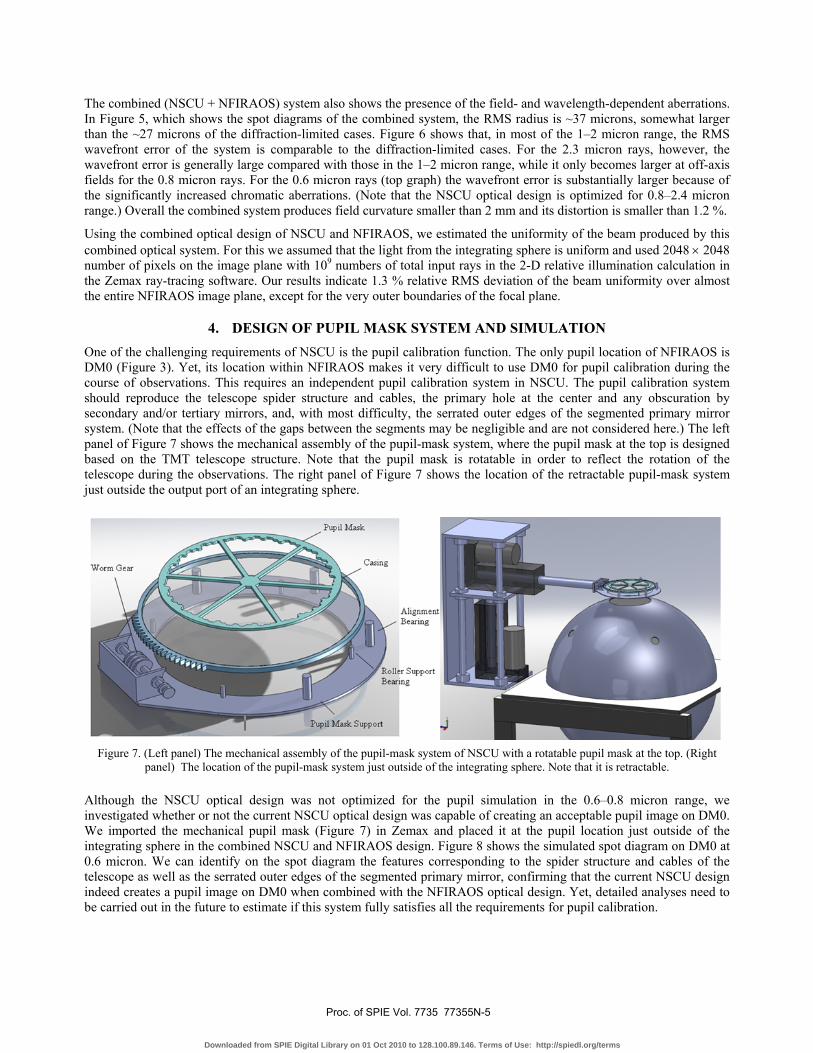
4. DESIGN OF PUPIL MASK SYSTEM AND SIMULATION One of the challenging requirements of NSCU is the pupil calibration function. The only pupil location of NFIRAOS is DM0 (Figure 3). Yet, its location within NFIRAOS makes it very difficult to use DM0 for pupil calibration during the course of observations. This requires an independent pupil calibration system in NSCU. The pupil calibration system should reproduce the telescope spider structure and cables, the primary hole at the center and any obscuration by secondary and/or tertiary mirrors, and, with most difficulty, the serrated outer edges of the segmented primary mirror system. (Note that the effects of the gaps between the segments may be negligible and are not considered here.) The left panel of Figure 7 shows the mechanical assembly of the pupil-mask system, where the pupil mask at the top is designed based on the TMT telescope structure. Note that the pupil mask is rotatable in order to reflect the rotation of the telescope during the observations. The right panel of Figure 7 shows the location of the retractable pupil-mask system just outside the output port of an integrating sphere.
Figure 7. (Left panel) The mechanical assembly of the pupil-mask system of NSCU with a rotatable pupil mask at the top. (Right
panel) The location of the pupil-mask system just outside of the integrating sphere. Note that it is retractable. Although the NSCU optical design was not optimized for the pupil simulation in the 0.6–0.8 micron range, we investigated whether or not the current NSCU optical design was capable of creating an acceptable pupil image on DM0. We imported the mechanical pupil mask (Figure 7) in Zemax and placed it at the pupil location just outside of the integrating sphere in the combined NSCU and NFIRAOS design. Figure 8 shows the simulated spot diagram on DM0 at 0.6 micron. We can identify on the spot diagram the features corresponding to the spider structure and cables of the telescope as well as the serrated outer edges of the segmented primary mirror, confirming that the current NSCU design indeed creates a pupil image on DM0 when combined with the NFIRAOS optical design. Yet, detailed analyses need to be carried out in the future to estimate if this system fully satisfies all the requirements for pupil calibration.
Proc. of SPIE Vol. 7735 77355N-5
Downloaded from SPIE Digital Library on 01 Oct 2010 to 128.100.89.146. Terms of Use: http://spiedl.org/terms

Figure 8. Pupil simulation spot diagram on DM0. The number in the left is in the unit of μm.
5. LIGHT SOURCES AND OPTO-MECHANICAL ASSEMBLY We investigated the properties of the commercially-available integration spheres and light sources which can be used for NSCU. The diameter of the integrating sphere was fixed to be ~50 cm (in diameter) because, to the best of our knowledge, integrating spheres of this size gives the best efficiency among all currently available ones from vendors. For the case of TX-20 integration sphere from Sphere Optics, which has ~50 cm sphere diameter with ~20 cm output port size and Tungsten-Halogen Xenon light sources, our preliminary calculations predict more than ~105 photons per detector pixel of the NFIRAOS-fed instruments in each J, H, K bands, although this number needs to be confirmed later with the real throughput of the instruments. The output beams of integrating spheres are usually measured to be uniform at 2% level over one degree field. This, together with the illumination uniformity of the combined NSCU and NFIRAOS optical system (see §3), may satisfy the NSCU requirement on the beam uniformity (< 5 %) of the overall 2-arcminute NFIRAOS field. Given that the NSCU field size is 4 degrees (in radius), we need more measurements on the off-axis uniformity of the beam from the integrating sphere to thoroughly understand its effects on the final uniformity of the calibration beams at the NFIRAOS image plane. For the wavelength calibration, we are currently looking into the possibility of using lines from both Thorium-Argon3 lamp and OH sky molecules to densely cover the NIR wavebands, which is different from the Gemini calibration system where Argon and Krypton pencil lamps are used1.
Figure 9 presents the current opto-mechanical assembly of NSCU, showing that all the components (such as the integrating sphere, pupil-mask system, lens assembly, and folder mirrors) fit within the given size of the NSCU envelope. The total mass of the current system is approximately 1.5 tons, satisfying the 2-tons limit requirement of the NSCU total mass. The main frame of the NSCU system is responsible for ~2/3 of the total mass. The location of the center of mass of the entire NSCU assembly is close to the geometrical center of the NSCU envelope.
Proc. of SPIE Vol. 7735 77355N-6
Downloaded from SPIE Digital Library on 01 Oct 2010 to 128.100.89.146. Terms of Use: http://spiedl.org/terms

6. CONCLUSION We have developed an opto-mechanical design of the science calibration system for the TMT NFIRAOS and client instruments. This system is optimized to provide highly-uniform f/15 calibration beams (both continuum and line) for the instruments in the NIR wavebands and pupil simulation function for NFIRAOS in the 0.6–0.8 micron range. The designed calibration system is composed of an integrating sphere with light sources, a pupil-mask system, a lens assembly, and fold mirrors. Our simulation results suggest that the current design is capable of producing a highly-uniform f/15 illumination at the TMT focal plane as well as producing pupil images at the pupil location (= DM0) inside NFIRAOS. Presently a single identical lens system consisting of a pair of achromatic triplets is used to cover the entire wavelength range of 0.6–2.4 micron both for instrument calibration and for pupil simulation, which produces somewhat significant chromatic aberration effects in the short wavelength range. A possible solution for this in the future is to develop two exchangeable separate lens systems optimized for instrument calibration in the NIR and pupil simulation in the optical wavebands, respectively, and the efforts for this development are currently underway.
Figure 9. Opto-mechanical assembly of NSCU.
Proc. of SPIE Vol. 7735 77355N-7
Downloaded from SPIE Digital Library on 01 Oct 2010 to 128.100.89.146. Terms of Use: http://spiedl.org/terms

REFERENCES
[1] Ramsay-Howat, S. K., Harris, J. W., Gostick, D., Daidlaw, K., Kidd, N., Strachan, M., and Wilson, K., "Gemini facility calibration unit," Proc. SPIE 4008, 1351-1360 (2000).
[2] Herriot, G., et al., "NFIRAOS: TMT narrow field near-infrared facility adaptive optics," Proc. SPIE 6272, 62720Q (2006)
[3] Kerber, F., Nave, G., and Sansonetti, C. J., "The Spectrum of Th-Ar Hollow Cathod Lamps in the 691-5804 nm region: Establishing Wavelength Standards for the Calibration of Infrared Spectrographs," The Astrophysical Journal Supplement, 178, 374 (2008).
ACKNOWLEDGEMENT
We thank Jenny Atwood, John Pazder, Scott Roberts, and John Rogers for their helps in this work.
Proc. of SPIE Vol. 7735 77355N-8
Downloaded from SPIE Digital Library on 01 Oct 2010 to 128.100.89.146. Terms of Use: http://spiedl.org/terms