The RumbleBug 1500 - Masih AHMED
138
EMAE 360: Design and Manufacturing II Professor: Dr. Sunniva Collins The RumbleBug 1500 An Inline4 Motorcycle Engine Joanna Rumbley, Masih Ahmed, Spencer Boyd, Stephen Finnegan, Carly Harris, Matthew Kaiser, Theodore Leung, Kevin Miller, Jonathan Shabtai, Tony Spalding Department of Aerospace and Mechanical Engineering Case Western Reserve University Cleveland, OH Prepared for Spartan Motorcycle Company December, 2015
Transcript of The RumbleBug 1500 - Masih AHMED

EMAE 360: Design and Manufacturing II
Professor: Dr. Sunniva Collins
The RumbleBug 1500 An Inline4 Motorcycle Engine Joanna Rumbley, Masih Ahmed, Spencer Boyd, Stephen Finnegan, Carly Harris, Matthew Kaiser, Theodore Leung, Kevin Miller, Jonathan Shabtai, Tony Spalding Department of Aerospace and Mechanical Engineering Case Western Reserve University Cleveland, OH Prepared for Spartan Motorcycle Company December, 2015

Table of Contents 1. Executive Summary 2. Goals and Objectives 3. Scope 4. Assigned and Derived Requirements 5. System and Subsystem Design
5.1. Relevant Technical Information and Calculations 5.1.1. Cold Air Standard Assumption Model 5.1.2. FuelAir Cycle 5.1.3. Final Engine Model 5.1.4. Journal Bearing Calculations 5.1.5. Cooling Calculations
5.2. Drawings: detail, assembly, CAD models 5.3. Bill of Materials 5.4. Materials and Manufacturing Methods
5.4.1. Crankcase 5.4.2. Valvetrain
5.5. Quality Control/Critical Characteristics 6. Testing and Assembly 7. Theory of Operations
7.1. Overall Functions 7.2. Order of Operation 7.3. Troubleshooting Common Issues
8. Failure Modes and Effects Analysis (FMEA) 9. Final Cost Estimate 10. Design Satisfies Requirements 11. Project Management
11.1. Work Breakdown Structure 11.2. Team Contributions 11.3. Final Gantt Chart
12. Acknowledgements 13. References 14. Appendix
A.1. Team Charter A.2. Product Design Specification A.3. Pugh Charts A.4. FMEA A.5. Calculations
1

A.5.1. MATLAB Code A.5.2. Piston Equations A.5.3. Heat Transfer and Cooling
A.6. List of Equations A.7. List of Abbreviations
2

3

1. Executive Summary
Introduction
Rumbley and the Rumblers are proud to present an innovative new engine that is ready to hit the market immediately. The RumbleBug 1500 is a 1500cc, inline style, four cylinder engine that is going to change the way motorcyclists ride. Problem The Spartan Motorcycle Company has called for a new, largedisplacement engine to use in a line of new cruiser motorcycles. Solution Rumbley and the Rumblers have designed an inline4 engine with the following key specifications:
1500cc displacement 4 cylinders up to 75 HP up to 42 MPG dry weight of 225 lbs.
Scope The scope for this engine has been limited to only the components that the team has deemed essential to the function of the engine. An electrical team will be required to complete the full design. Additionally, all other parts of the motorcycle will need to be built and designed by other engineers within the Spartan Motorcycle Company. Costing The RumbleBug 1500 can be manufactured and assembled for under $3,000.00. Many of the parts can be manufactured in house, but several parts, all of which are outlined in this report, must be purchased from outside companies.
4

2. Goals and Objectives
The main goal of Rumbley and the Rumblers through the completion of this project was to satisfy the requirements defined by the Spartan Motorcycle Company. This included restrictions on the physical design of the engine and type of engine; the design is also required to comply with federal noise and emissions standards. These requirements are described in more detail in Section 4 of this report. The team also aimed to design the engine to be as marketable as possible; considerations to this end included cost, efficiency, size, and weight of the engine.
None of the members of Rumbley and the Rumblers had any significant prior knowledge or experience with motorcycle engines. Thus, the team had a primary objective for all members to learn and understand the components of a motorcycle engine, how a motorcycle engine works, and key design points of a motorcycle engine. The team also strived to maintain a group dynamic that was both professional and respectful throughout the project and divide work as evenly as possible so that all members could feel that they contributed significantly.
5

3. Scope Given the involved nature of the subject of this project and limited amount of time and
resources available, defining and constantly reevaluating scope was essential to the team’s success. The scope was initially limited generally to essential engine components. However, as progress was made, the scope was narrowed further to disclude specific parts of the engine not directly involved with the design requirements. Examples of these parts include the alternator and the starter. These parts are necessary to start and run the engine, however, these components would typically be designed by an electrical team or purchased from another company. Therefore, they are not in the design scope.
Other items were deemed out of scope due to limited time and resources. While some of these items may have been included in a similar design, the team made the decision to omit them because they are not critical to the function or design of the engine. Examples of these parts include the exhaust heat shield, thermostat housing, and the fuel injection wiring harness.
Additional components of typical new product development were deemed out of scope because the team focused solely on mechanical engineering design of the engine. The team did not include marketing strategies or any detailed plans for future iterations of the engine. However, several different analyses pertaining manufacturing and materials selection are included. These will appear in later sections of the paper. 4. Assigned and Derived Requirements
Assigned Engine Requirements Assigned Performance Requirements
2 or more cylinders, 4stroke cycle Capable of 5000 rpm continuous service, idle at 800 rpm
Displacement: 1500 to 1800cc Powers a sixspeed transmission
Fuel injection, spark ignition Must meet all relevant specifications and standards for safety, fuel efficiency, noise and emissions
Runs on standard gasoline
Compression ratio 9:1 to 10:1
6

Derived Engine Requirements Derived Performance Requirements
Inline 4 cylinder configuration 100150 HP at 5,000 RPM
Cost of $8,000 $10,000 for the consumer
Lifespan of at least 60,000 miles with regular maintenance
Weight is at or below 300lbs dry Meets average fuel economy for a motorcycle engine 3540 MPG[13]
Meets relevant emission standards, less than 12g/km CO and less than 0.8g/km HC + NOx[9]]
Noise level is below 82 dB when traveling at 35 mph or less from 50 feet away and below 86 dB at more than 35 mph. [17]
7

5. System and Subsystem Design 5.1 Relevant Technical Information and Calculations The team’s thermodynamics specialist created several models in order to understand important characteristics of the engine. First, a cold air standard model was used to select general engine characteristics, such as displacement, compression ratio, and number of cylinders. Next, a fuelair cycle model allowed for the consideration of additional engine effects. Finally, a third model included additional features and enabled a more refined analysis of the engine model. 5.1.1 Cold Air Standard Assumption Model In Microsoft ExcelTM, engine data parameters were chosen and analyzed using a thermodynamic state model. Due to this being a cold air standard model, the ratio of specific heats is constant, the working fluid is assumed to be an ideal gas, and all losses from pumping processes are ignored. The number of cylinders NCyl, the total displacement V, the compression ratio RC, engine speed n, boretostroke ratio, air to fuel ratio, intake air temperature T0, and intake air pressure P0 were all predetermined for the analysis. Air and fuel properties were also given, namely specific heats CP and CV, ideal gas constant R, ratio of specific heats γ, and low heating value of the fuel QF. Using the model, the volume per cylinder was calculated; subsequently, the amount of air in the cylinder was calculated using the specific volume of the air.
V cyl = NCyl
V RC
R + 1C
(Eqn. 1)
MA = RT 0
P V0 Cyl (Eqn. 2)
From this point, the temperature and pressure of the air after isentropic compression were calculated using isentropic relations derived from the isentropic case of the polytropic formula:
V onstant P γ = C (Eqn. 3) After the pressure and temperature were calculated postcompression, the amount of heat added to the system was calculated using the mass of air in the cylinder MA, the constant volume specific heat of air CV, the air to fuel ratio A/F, and the low heating value QF:
TCombustion =QA/F
MAF
M (1+ )CA1A/F V
+ TCompression (Eqn. 4)
8

Which is equivalent to
TCombustion =QF
(A/F + 1)CV+ TCompression (Eqn. 5)
It is assumed that the mass in the cylinder is a combination of the air mass and the fuel mass; therefore, the combusted fuel has the same specific heats as the air. After finding the combustion temperature, the combustion pressure can be calculated:
PPCombustion =TCombustionTCompression Compression (Eqn. 6)
After combustion, the cylinder moves down due to the change in pressure of the gas. This is the portion of the cycle that generates work. Using the same relation as the compression stroke, the expansion temperature and pressure are:
TExpansion = TCombustion( 1RC)
γ−1(Eqn. 7)
PExpansion = PCombustion( 1RC)
γ(Eqn. 8)
With a known compression ratio, the efficiency can be found using the formula:
ηth = 1 −1
RCγ−1 (Eqn. 9)
This model is fairly inaccurate, as it does not take into account many factors, including pumping losses, changes in specific heats, volumetric efficiency, friction losses, and additional performance parameters. To increase the accuracy of the analysis, it is necessary to improve the model to include more of these factors. 5.1.2 FuelAir Cycle Using a onedimensional model as opposed to the zerodimensional cold air standard assumption model, which only includes intrinsic properties, improves the accuracy of the model significantly. In this model, the position of the cylinder must be modeled with respect to crank angle and therefore time, since it is assumed that engine speed is constant. Since the cycle starts
9

at BDC with the compression stroke, the formula for piston position with respect to crank angle is:
(cos θ ) x = 2S + 1 +√l sin θ2 − (2S)
2 2 − l (Eqn. 10) Given this position parameter, the pressure and temperature can now be calculated. This is necessary because the pressure and temperature cannot be calculated analytically if specific heats change. Assuming an initial temperature and a pressure based on a volumetric efficiency curve [10], and relations for specific heats, the following relation was iterated through 180 degrees of rotation to obtain the temperature and pressure during compression.
T i = T i−1( xixi−1)γ − 1i−1
(Eqn. 11)
P i = P i−1( T iT i−1)
γ i−1γ − 1i−1 (Eqn. 12)
Using these data points, specific volume was calculated for several volumetric efficiencies and input into the NASA CEA program to get both emissions data and post combustion temperatures and pressures. Friction was modeled from an equation in Internal Combustion Engine Fundamentals.[10]
mep .97 .15( ) .05( )f = 0 + 0 N1000 + 0 N
10002
(Eqn. 13) The equation gives frictional and pumping losses in terms of mean effective pressure in bar, related with engine speed N in RPM. This value is converted to work lost per cycle, and then subtracted from the work per cycle. Work per cycle is calculated using the pressure and change in volume, summed iteratively over the compression and expansion strokes:
(V )W = ∑
2
P +Pi i−1i − V i−1 (Eqn. 14)
5.1.3 Final Engine Model The final model is similar to the fuelair model, but it makes important changes. This model includes heat loss from cooling, as well as noninstantaneous combustion, and a more accurate friction parameter.
10

Figure 5.1: Engine power and torque curves based on the final model
Heat loss is calculated from the Hohenberg formula, which describes the heat transfer between the hot gases inside the cylinder and the cylinder wall [13]. In the equation, h is the convective heat transfer coefficient, p is the instantaneous pressure, Vs is the swept volume of the piston, T is the gas temperature, and vp is the mean piston velocity.
(v .4)h =
V Ts0.06 0.4
129.8p0.8p + 1 (Eqn. 15)
This expression for the convective heat transfer coefficient was added to the MATLAB program and calculated for every instance. Cooling power Q is defined as
A (T )Qi = hi i gas,i − Twall * tstep (Eqn. 16)
A is calculated based on the piston position, and the wall temperature is assumed to be 150 C. The total value is then multiplied by the step duration. Each value of the heat lost per step is summed, then divided by total time for a full cycle to occur. This gives us the required cooling power.
11

Next, losses due to friction were calculated using a more accurate equation. The model now uses the Chen and Flynn model [22], which is said to avoid underestimating frictional losses, as it takes into account pressure loading. The equation uses the maximum pressure in the cylinders during the cycle, and the mean piston velocity.
mep(bar) .137 62vf = 0 + 200pmax + 1 p (Eqn. 17)
This equation is used in the same way as the fmep equation in the fuelair model. The final adjustment in this model is the use of a Weibull function to approximate noninstantaneous fuel burning. Input variables to the function are initial combustion angle, angular combustion duration, and two constants, a and m [13]. Defining a as 5, and m as 2 gives a good approximation.
(θ) xp[− ( ) ]x = 1 − e a Δθbθ − θ0 m+1 (Eqn. 18)
The change in this number over each time step is multiplied by the amount of fuel, as well as the heating value of the fuel, to find the total amount of energy added to the system per time step. The amount of heat added to the system is compensated for in the temperature term as explained above for the cold air standard model.
12

Figure 5.2: Pressurevolume diagram of final model
Fuel economy is calculated in this model by taking the mass of fuel used per cycle, and the speed of the motorcycle. Drag is estimated using the square of speed equation summed with sample rolling resistance data. The drag value is multiplied by the motorcycle speed to obtain the power requirement to overcome the force of drag. Engine speed and throttle opening are adjusted to match the total drag power requirement. Dimensional analysis is used to give a number in MPG, which is calculated to be 42 miles per gallon at a steady speed of 70 MPH. Maximum thermal efficiency is between 25 and 27 percent. 5.1.4 Journal Bearing Calculations Camshaft Lubrication From the Stone book, we can calculate load on the camshaft based on lift, spring constant, equivalent mass of the rocker and valve assemblies, spring preload, and the acceleration of the assembly [13]. It is found that the maximum load at low speeds is 190 lbs, and at high speeds, the maximum load is 380 lbs. This is assuming a preload of 100 lbs. Varying the preload can make the bearing pressure more consistent, since the acceleration of the valve assembly will add about 200 lbs of force at an engine speed of 5000 RPM. Assuming a clearance ratio c/R of 0.001, and a L/D ratio of 1/4, the Sommerfeld number can be between 0.02 and 0.5. The minimum condition
13

will occur at low speed and the maximum condition will occur at high speed. At high speed, maximum bearing pressure is 10.5 MPa, and minimum is 2.5. At low speed, maximum bearing pressure is 5 MPa, and minimum is still 2.5.
S = ( cR)2PμN
(Eqn. 19) Using SAE 10W40 oil, which has a viscosity of 20 mPas at 70 C, we get that the Sommerfeld number at high speed and maximum pressure is 0.079, which is in operating range. At low pressure at high speed, the number is 0.32, which is also in range. At low speed and high pressure, the Sommerfeld number is 0.027, and at low pressure it is 0.054. This means our camshaft bearings will work. In order to calculate the oil pumping rate in the bearings, we must consult the Raimondi Boyd design charts for flow rate Q. At the maximum engine speed, the sommerfeld numbers and bearing ratio gives us a flow rate that:
.5 .25 ≤ QRcnL ≤ 6 (Eqn. 20)
On average, this value will be about 5.7. Plugging in the rest of the numbers, gives us that Q = .25 cubic centimeters per second. Percent of flow exiting the bearing is about 9095%, so the total leakage rate is .23 cc/s per bearing. There are 5 bearings, so total flow rate at 2500 RPM through the camshaft bearings is 1.2 mL/s Main Bearing Lubrication The main bearings have a L/D ratio of 3/4. Using the Raimondi Boyd charts, the characteristic number must be between 0.07 and 0.27. In table 13.2 of the Juvinall textbook, it is estimated that the pressure in the main bearings is between 4 and 5 MPa. Using 5 MPa, and an oil temperature of 80 C, (making the viscosity 15 mPas,) a clearance ratio of 0.001, and a speed of 5000 RPM, we find that the characteristic number is 0.25. The flow variable is then 4.5, and the denominator is approximately 1, so flow rate in the bearing Q is 1.15 cc/s. QS is about 65% of Q, so the flow rate is 0.75 cc/s. Given that there are 5 bearings, the total flow rate is 3.75 mL per second. Connecting Rod Lubrication The connecting rod bearings have a length to diameter ratio of 4/5. In the Raimondi Boyd charts, the optimum characteristic number is between 0.07 and 0.25. In the Juvinall text, the pressure of the connecting rod bearings vary between 10 and 15 MPa. Using a pressure of 12.5 MPa, an oil temperature of 80 C, a viscosity of 15 mPas, a clearance ratio of 0.001, and an RPM of 5000, the characteristic number is 0.1, which is in range. The flow variable Q/RcnL is 4.7 in the design
14

chart, and Q is 2.5 cc/s. Leakage percentage is 80%, so leakage rate QS is 2 mL/s per bearing. There are 4 bearings, so total flow rate is 10 mL/s. Conclusion Adding all of the flow rates together gives a total flow rate needed, which is 0.015 L/s, or 0.9 liters per minute. SAE 10W40 oil is specified in the calculations, as it gives the desired viscosities. From these values, an oil pump can be specified. 5.1.5 Cooling Calculations In order to find the amount of heat needed to be removed from the cylinders to keep the engine cool, we must find the heat transfer coefficient h between the hot gasses inside the cylinder and the cylinder wall. In the Stone book,[13] there are many correlations. A simple correlation, which has sufficient accuracy in practice is the Hohenberg formula:
(v .4)h =V Ts0.06 0.4
129.8p0.8p + 1 (Eqn. 21)
Figure 5.3
15

From the following equation, the total heat transfer Q can be found.
A(T )Q = h gas − Twall (Eqn. 22) Assuming a constant inner wall temperature of 150 C, though a 10 % reduction in cooling power will increase wall temperature by 10 C, in the team’s final MATLAB model, Q at 5000 RPM is 0.227 kJ per cylinder per 4 strokes. Simple conversion to imperial units, Heat loss rate from the gas to the walls is Q = 25.6 HP at 5000 RPM Temperature delta across the cylinder walls to the base of the fins is approximately 95C, assuming an average of 2 inches thickness from cylinder wall, x, to the base of the fins, an area, A, of about 100 in2 between the cylinder walls and the base of the fins, and using the heat conduction formula with a thermal resistor network model.
k (T )Q = xA
wall − T∞ (Eqn. 23) The temperature of the base of the fins will be 50 C Based on the size of the engine, the critical dimensions and material properties of the fins are:
length of fins ≈ 17 inches width of fins ≈ 3 inches thickness = .1 inches, we kaluminum = 151 W/mK Perimeter ≈ 23 inches
The temperature at the outer surface of the fins is approximately 40C.[3] At Tair = 30C, kair = .027 W/mK, viscosity is 0.019 mPas. The air speed is 30 m/s. The Reynolds number is about 8x10⁵, using the formula for combined laminar and turbulent flow, the Nusselt number is found to be 975 with the next equation.
u (.037Re 71)Pr N = 4/5 − 8 1/3 (Eqn. 24) Relating the nusselt number to the heat transfer coefficient h, it is found that
h = LNu k (Eqn. 25)
16

The heat transfer coefficient h is calculated to be 57.9 Wm2K1. Plugging all the values into the next formula, Cooling power per fin can be calculated. [21]
(Eqn. 26)
Q is found to be 461 watts per fin. Dividing necessary cooling power by the power per fin gives us that 42 fins in total are needed, or 21 per side. Natural convection case: At an idle of 800 RPM and an air to fuel ratio of 15:1, the engine needs approximately 8 percent throttle to maintain engine speed. At this operating condition, the engine must be cooled with about 600 watts of cooling power. If not the engine would eventually fail. In the case that the engine is idling, and the motorcycle is stopped, the cooling fins are operating in the natural convection regime, which means cooling capacity is severely reduced. In order to understand if the engine would fail under these conditions, and how quickly it would fail if it did happen, natural convection calculations must be done. Ideal fin spacing for natural convection is defined by a formula based on fin length and Rayleigh number:[4]
.714Sopt = 2L
Ra1/4 (Eqn. 27) The heat transfer coefficient is then defined by:
.31h = 1 kSopt
(Eqn. 28) First, we must calculate the Rayleigh number. This is done using the following formula, where g is gravity, β is the coefficient of volume expansion, TS is the fin temperature, T∞ is the ambient temperature, L is the characteristic length, ν is the kinematic viscosity, and Pr is the Prandtl number.
a PrR = ν2gβ(T −T )Ls ∞
3
(Eqn. 29)
17

Using an ambient temperature of 30 C, an average fin temperature of 50 C, and a film temperature of 40 C, the Rayleigh number is calculated to be 1.746 x 10⁸. From this number, we can calculate the optimal spacing for the fins Sopt, and the heat transfer coefficient h. Sopt is found to be 1 centimeter, and from there, h is 3.5. However, these numbers are for vertical fins on a vertical heat sink, which is the ideal case for natural convection. On our engine, cooling is optimized for forced convection, with air moving along the engine from front to back. From a paper comparing horizontal and vertical baseplate heat sinks, it is seen that a vertical fin arrangement is 4.4 times as effective as a horizontal fin arrangement.[5] Thus, the heat transfer coefficient is then 0.8 for the RumbleBug 1500 under natural convection conditions. With a temperature difference of 20 C, using this formula:
A(T )Q = h s − T∞ (Eqn. 30)
The heat dissipated per fin turns out to be about 2 watts per fin! Assuming this, the engine would need about 300 fins to not fail under natural convection conditions. Clearly this is not feasible. Using the calculated 42 fins, the engine would only have 85 watts of cooling power available, not nearly enough to keep the operating temperature low enough, and as such, the engine will fail at some point due to overheating. In the natural convection regime, fins aren’t the only source of significant cooling, but this will not increase cooling power significantly. Estimating that the engine can be cooled off at a rate of 120 watts, and that the necessary cooling power is 600 watts, the engine will heat up at a rate of 480 watts. Knowing this rate of heat accumulation, the specific heat of aluminum, the density of aluminum, the volume of aluminum needed to be cooled, and maximum allowed temperature of aluminum, this can be easily calculated. The density of aluminum is 2700 kgm3, the specific heat is 0.9 kJkg1K1, the maximum temperature is 250 C, the initial wall temperature is 150 C, and the volume of the aluminum dissipating the heat is 0.0046 m3. From these values, we found that the time to failure is 38 minutes. If the required engine cooling power is doubled, then the engine would fail in 16 minutes. This is a reasonable amount for sitting in traffic on a warm day, but the rider should still be made aware of this condition. 5.2 Drawings: 1. Drawing of Assembly, 2. Drawings
18

19

20

21

22

23

24

25

26

27

28

29

30

31

32

33

34

35

36

37

38

39

40

41

5.3 Bill of Materials
Part Number Engineer QTY Description Material Supplier
Manufacturing Method
Tooling cost
Unit Cost
Total Cost
Weight (lb) Rev
G1001 Joanna 1 Engine block Aluminum 356
Die cast with cast iron insert, postmachined $11,036.00 $89.77 $89.77 90.6 3
G1002 Masi 1 Crankshaft Steel 4340 Forging, postmachining $3,553.00 $67.15 $67.15 24.15 2
G1003 Joanna 10 Main bearing half
Steel back w/ layer of copper lead alloy
Machined steel backing/poured+sprayed layers $7.75 $77.50 0.046 1
G1004 Kevin 8 Connecting rod bearing
Steel back w/ layer of copper lead alloy
Machined steel backing/poured+sprayed layers $3.31 $26.48 0.009 2
G1005 Matt 4 Connecting rod Steel 4340 Forging, postmachining $3.81 $15.24 0.344 2
G1006 Matt 4 Connecting rod cap Steel 4340
Forging, postmachining $3.52 $14.08 0.056 3
G1007 Masi 4 Pistons Aluminum 390
Die cast, postmachining $2,259.00 $4.86 $19.44 1.46 2
G1008 Teddy 8 Connecting rod bolts Stainless steel
ARP via Jegs $7.99 $63.92 0.16 1
G1009 Teddy 4 Wrist pins Steel 4340
Milling, surface hardening $18.00 $72.00 0.217 1
G1010 Teddy 3 Main caps Aluminum 6061
CNC machining $43.09 $129.27 3.9 1
G1011 Teddy 1 Flywheel Steel 1045 Turning, hobbing $54.53 $54.53 6.98 1
G1012 Kevin 4 Cylinder sleeve Cast iron Die casting, postmachining $3.40 $13.60 1.59 2
G1013 Kevin 2 Outer main cap Aluminum 6061 Machining $52.03 $104.06 1.56 1
G2001 Stephen 1 Cylinder head Aluminum 356
Die casting, postmachining $7,789.00 $42.30 $42.30 26.38 1
G2002 Stephen 4 Exhaust valves
214 N Austenitic steel w/ nitriding coat
Forging, post machining, heat treated $6.13 $24.52 0.76 1
42

G2003 Kevin 8 Valve springs Steel Crower $2.23 $17.84 0.6 2
G2004 Kevin 8 Valve spring retainers Steel J&P Cycles $5.00 $40.00 0.04 1
G2005 Kevin 8 Valve keepers Steel J&P Cycles $2.50 $20.00 0.06 1
G2006 Stephen 4 Intake valves Steel 4340 w/ nitriding coat
Forging, post machining, heat treated $21.50 $86.00 0.8 1
G2009 Kevin 8 Valve guide Bronze Machining $6.00 $48.00 0.03 1
G2012 Kevin 10 Camshaft bearings
Steel back w/ layer of copper lead alloy Machining $3.31 $33.10 0.09 1
G2013 Kevin 1 Camshaft Chilled iron casting Chill casting $23.04 $23.04 3.31 2
G2014 Kevin 5 Camshaft bearing caps
Aluminum 6061 Machining $13.56 $67.80 0.03 1
G2015 Kevin 1 Head gasket Copper Stamping press $36.50 $36.50 0.11 1
G2017 Kevin 1 Camshaft/valve cover
Aluminum 356 Die casting $1,147.00 $3.76 $3.76 2.23 2
G2018 Kevin 8 Rocker arm Stainless steel
Auto 7 via Auto Parts Warehouse $10.05 $80.40 1.6 2
G3001 Tony 1 Oil pan Aluminum 356 Punch Press $3.76 $3.76 4.46 3
G3003 Carly 1 Intake manifold Aluminum 6061
Bending and welding $100.00 $100.00 7 1
G3004 Carly 1 Throttle body assembly
Auto Parts Warehouse $123.04 $123.04 3 1
G3005 Yoni 1
Exhaust manifold/header
Stainless steel 316
Bending and welding $100.00 $100.00 7 1
G3006 Yoni 1 Crankshaft timing pulley Aluminum
Auto Parts Warehouse $20.00 $20.00 0.5 1
G3007 Carly 1 Timing cover Aluminum 6061 Die casting $6,118.00 $13.56 $13.56 0.376 1
G3009 Yoni 1 Starter Auto Parts Warehouse $56.10 $56.10 10 2
G3010 Spencer 1 Dip stick
HDPE handle/steel tube
Auto Parts Warehouse $7.95 $7.95 0.1 2
43

G3011 Spencer 4 Fuel injectors
Accel via Auto Parts Warehouse $43.52 $174.08 3 2
G3013 Carly 4 Spark plugs Advance Auto Parts $2.49 $9.96 1 2
G3014 Carly 2 Ignition coils
AC Delco via Auto Parts Warehouse $42.82 $85.64 1 2
G3015 Carly 4 Spark plug wires
Taylor Cable Via Auto Parts Warehouse $9.82 $39.28 1.2 2
G3017 Tony 1 Tensioner pulley
Advance Auto Parts $35.00 $35.00 1.2 2
G3018 Tony 1 Alternator Auto Parts Warehouse $110.00 $110.00 8 2
G3019 Tony 1 Timing belt
Rubber with fiber reinforcement
Advance Auto Parts $60.00 $60.00 0.3 2
G3020 Tony 1 Oil pump Auto Parts Warehouse $200.00 $200.00 9 2
G3021 Kevin 1 Camshaft timing pulley Aluminum
Auto Parts Warehouse $15.00 $15.00 0.15 2
G4001 Kevin 1 Full assembly $31,902.00 $2,408.67 224.248
5.4 Materials and Manufacturing Methods 5.4.1 Crankcase
Engine Block The engine block will be made out of Aluminum 356. The block will be cast with cast
iron insert and postmachined. The aluminum was chosen due to its relatively low cost and low weight, and for its high thermal conductivity and ease of casting
Gaskets The head gasket will be stamp pressed out of copper. Stamp pressing allows for quick
manufacturing of large quantities of parts with relative ease. Copper is a malleable metal, which as the head gasket, allows for a good metaltometal contact between the engine block and the cylinder head.
Crankshaft
44

The crankshaft takes the most load of perhaps any part in the engine assembly. For strength and cost effectiveness, the crankshaft will be forged out of 4340 high strength steel. Carbon fiber and aluminum were considered, but discarded for financial, strength, and manufacturing complexity reasons. After the general part is forged, the part will be CNC machined to match the tolerances and critical characteristics required to meet the mating sections with bearings, connecting rods, and finally, the flywheel.
The main caps hold the crankshaft in place. The main caps must be able to withstand forces on the crankshaft without shearing, but also must be relatively light to avoid significant energy loss. Therefore, the main caps will be manufactured by CNC machining from an aluminum 6061 rectangular bar. Three main caps per engine will be made.
Connecting Rod The connecting rods will be made out of Steel 4340. It will be forged and post machined. Oil Pan The oil pan will be be made out of Aluminum 356. We will manufacture this part using
punch press. Bearings The bearings will be made out of steel back with a layer of copper lead alloy. The part
will be machined. Connecting Rod Bolts The connecting rod bolts hold the main body and the cap of the connecting rod together.
The bolts will be subjected to high velocities and strong forces. The bolts must be able to withstand such an environment without shearing. It is also more financially sound to purchase bolts. Therefore, the connecting rod bolts, made from stainless steel, will be purchased from ARP via Jegs.
Flywheel The flywheel transmits torque force continually from the engine. This maintains a
constant angular velocity of the crankshaft, and reduces jerking. The flywheel will be subjected to high velocities. Therefore, the main flywheel body will be manufactured by turning from a steel 1045 rod. The outermost surface is hobbed at the given gear dimensions. One flywheel per engine will be made.
Piston Assembly (Compression Ring, Wiper Ring, Oil Ring, Wristpin, Cylinder Head) The wrist pins connect the pistons to the connecting rods. The wrist pins are subjected to
extremely high temperatures, heavy shear and bending loads, and extremely high pressure loads. Therefore, the wrist pins will be manufactured by milling from a Steel 4340 rod, and then surfaced hardened for thermal resistance and reduced friction. Four wrist pins per engine will be made.
Pistons The pistons are manufactured by CNC machining from an aluminum 390 casting. Four
pistons per engine will be made. The piston is subjected to high velocity, rapid changes in
45

accelerations, and high temperatures. Additionally, the piston interfaces with the engine block and needs to maintain a critical surface finish. For this reason, the cast will be CNC machined to make sure everything is up to quality. Aluminum 390 was selected for its low thermal expansion relative to other Aluminum alloys, leading to a reduction in thermal stresses, as well as for its low density, which helps reduce weight of the piston.
5.4.2 Valvetrain
Camshaft The camshaft is made from chilled cast iron, a material that has high strength, hardness,
toughness, and wear resistance. Chilled casting is done with metal molds, which diffuses heat faster and cause the part to cool quickly. The high cooling rate creates a hardened structure.[14]
Timing Belt The timing belt is made from a fiber reinforced rubber to allow better gripping of the
camshaft and crankshaft timing pulleys. Advanced Auto Parts is the supplier of the timing belt. Intake/Exhaust Valves (Springs, Retainers, Rocker Arms) The intake and exhaust valves are both forged then machined down to a smooth surface.
Afterwards, they undergo a heat treating process called nitriding. Nitriding diffuses nitrogen into the metal surface to strengthen the material and create a hardened surface. This increases its resistance to wear. The intake valve is made from ANSI steel 4340, which is able to withstand high temperatures. The exhaust valve is made of an austenitic alloy 214 N, which contains 21% chromium and close to 4% nickel. It can withstand temperatures higher than what 4340 steel can. The exhaust valve must have enough strength and heat resistance to withstand the pressure of combustion and the high amount of heat from exhaust gases flowing around the valve.
Fuel Injector For selection of the fuel injector, the team had to determine the required flow rate of the
fuel. In order to find the maximum flow rate of the fuel, maximum air flow rate through the engine is calculated, and then divided by air to fuel ratio. With these specifications, the total maximum flow rate of fuel was determined to be 5 g/s, or 39.68 lbs/hr. The group decided to use a total of four fuel injectors, one for each cylinder. With this configuration, each injector required a flow rate of 10 lbs/hr.
Given the required flow rate of the fuel, the group selected the Accel A35150115 Fuel Injector. This fuel injector can facilitate a maximum flow rate of 15 lbs/hr.[2] This performance number approximately matches the maximum flow rate calculated and is well over the required flow rate, which ensures that the engine will always receive enough fuel to operate without exceeding the emissions standards. In order to better match the flow rate, it is also possible to adjust the fuel pressure regulator and increase/decrease the pressure if desired.
Intake and Exhaust Manifolds
46

The intake and exhaust manifolds are very similar and therefore will be manufactured using the same method. The manufacturing process includes welding of various manifolds and bending them in the right shape to fit with other components of the engine and the engine block. We have decided to produce the intake manifold using aluminum (6061) and the exhaust manifold from Stainless Steel 316. The aluminum was chosen for the intake manifold due to its relative low weight and cheapness. However, we decided to manufacture the exhaust manifold from stainless steel 316 as it will stand up to the heat of the exhaust gases and will be more appealing to the customer.
5.5 Quality Control/Critical Characteristics
Scope of Quality Control Division:
Quality control is not responsible for setting tolerances, determining critical characteristics, or
deeming parts CSIs. That said, the design engineers can work with the Quality Engineers to
make these decisions, as the quality engineers are going to be testing for these tolerances and
characteristics, as well as taking the precautions to fix the part where these criteria are met. By
having a Quality control division and quality inspection plan, the team will be able to improve
the quality of the product as well as lead to early defect detection.
5.5.1 Individual Parts:
Definitions:
Critical Characteristic – Any feature throughout the lifecycle of a Critical Safety Item, such as
its dimension, tolerance, finish, material or assembly, manufacturing or inspection process,
operation, field maintenance, or depot overhaul requirement that if nonconforming, missing or
degraded may cause the failure or malfunction of a Critical Safety Item.[6]
Critical Safety Item (CSI) is an item (part, assembly, installation, or production system) that, if
missing or not conforming to the design data, quality requirements, or overhaul and maintenance
documentation, would result in an unsafe condition per the established risk acceptance criteria.
CSIs include items determined to be “life limited”, “fracture critical”, “fatigue sensitive”, etc.
47

The determining factor in CSIs is the consequence of failure, not the probability that the failure
or consequence would occur.[6]
Materials:[20]
Gidding & Lewis High Accuracy Coordinate Measuring Machines (CMM)
Hommel Turbowave 8000 (the latest surface finish measuring equipment)
PAT Gauge Incometer (most accurate instrument for cylinder bore measurement)
AtlasCopco – (DCTorqueing of critical fasteners)
Cold Dyno spin testing (oil pressure, oil flow, compression and torque)
ISO9002, ISO/TS16949, ISO14000
Six Sigma Quality Process
Purchased Parts:
All purchased parts will be unboxed and visually inspected upon initial contact. Parts that pass
inspection are to be entered into the assembly area. CSI items are inspected as needed before
admittance. Parts that do not pass inspection are to be placed in a quarantine cage until shipping
logistics proceed to return the item to the vendor. No assemblies are being purchased.
Manufactured Parts:
All manufactured parts will be visually inspected upon final processing. Parts that pass
inspection are to be entered into the assembly area. CSI items are inspected as needed before
admittance. Parts that do not pass inspection are to be placed in a quarantine cage until the part
can be destroyed, reused, or remanufactured.
Specific the quality control tests to be performed:
Visual:
Visual inspection of all parts, sorting and grading of the core of the engine block.
Crack Detection:
48

Magnetic particle inspection (MPI) inspection of all block and all cast iron cylinder heads. By
attaching an anode and a cathode, a machine induces current and detects the magnetic field that
the part emits. Cracks can be detected from inconsistencies in the magnetic field. [20]
Air Gauging: [20]
Heads – gauging of valve guides on all engines. gauging of lifter bores, and cam bores on
all overhead cam (OHC) engines.
Crankshafts – gauging of all rod and main bearing journals diameters.
Connecting Rods – gauged for: Bearing and pin bore diameters, center to center
dimensions to measure rod stretch, rod bend and/or twist.
Engine Block – gauging of all cylinder bores for diameter and roundness after final
honing operation.
Bearings – All surfaces tested for cracks and spalling – the life of these parts will
determine the life of the engine.
Dial Bore Gauging[20]: All crank main bearing bores and all cylinder bores on engine block
measured for diameter and distortion.
6. Testing and Assembly
6.1 Assembly
The assembly of the RumbleBug 1500 will take place in our manufacturing facility. The
engine will be assembled using an assembly line format with stations devoted to individual steps
of the process. Each component, manufactured or purchased, will be tested prior to assembly to
ensure a quality product is produced.
The assembly of the TSF 1700 will begin with the engine block which houses all of the
engine components. The cylinder sleeve is manufactured first. The machining tool will carve a
crisscross pattern on the cylinder walls known as crosshatch which helps with lubrication as the
oil will cling to the grooves in the pattern further allowing the piston to move smoothly. The
49

cylinder sleeve is then included in the casting of the engine block. After the engine block is cast
and its critical surfaces finish machined, it will move down to the assembly line upside down.
Assembly starts with the engine block, which acts as the core of the engine, housing
many of the components. The engine block arrives from manufacturing after being cast and
finish machined. Next, the crankshaft arrives and the reluctor ring, a magnetic device, is shrunk
fit to the end of the crankshaft. Then a timing gear is fitted to the end of the shaft. The crankshaft
is then spun in a test rig to evaluate its balance and determine whether any more material needs
to be removed.
The connecting rods are then attached to the pistons and the wrist pins are pressed in. The
piston rings are mounted and the pistons are put in place in the cylinders.
Half of the crankshaft bearings then are set in place in the engine block. The crankshaft
is lowered into the engine block where it rests on the bearings. Then the other half of the
bearings are put in place and the the main bearing caps are bolted on. The outer main bearing
caps on either end of the engine have a sealant applied to them so that they seal against the
engine block when they are installed.
The connecting rod bearings and bearing caps are then mounted to the connecting rod and
the crankshaft. Next the oil pan is bolted on to the bottom of the engine block with a paper gasket
between the mating surfaces to seal in oil.
While the engine block and crankshaft are being assembled, the head assembly is also
being assembled. The head comes from manufacturing after being cast and critical surfaces are
machined. The valves are inserted through the bottom of the head and then the valve guide is
inserted through the top of the head. Next, compressed springs are placed around the valve
stems. The valve keepers and valve spring retainers are then put in place, securing the springs.
The camshaft now comes from being finish machined and the timing gear is fitted in
place. The camshaft bearings are then set in place and the camshaft is lowered into place on top
of them. Then the other camshaft bearing halves are set in place and the bearing caps are bolted
on.
Next the rocker arms are bolted in place over the camshaft and valves. The camshaft is
then spun in order to check the alignment and fitting of all of the valve and timing components.
50

Once everything else is in place, the spark plugs are screwed in the the head. The head assembly
now undergoes vacuum decay testing[20]; All head and valve assemblies on cylinder head are
quantified for leakage using a vacuum decay process.
Now that the engine block and head assemblies are complete, they are combined. The
head is bolted on with a copper head gasket to seal the cylinders. Now that the head has been
attached to the engine block, the flywheel can be mounted to the output shaft. Next the timing
gears are aligned and the timing belt is mounted over the two timing gears. Finally, the intake
and exhaust manifolds are mounted to the head with gaskets to seal the flow. Now the engine is
ready to undergo full assembly testing procedures.
6.2 Testing
Pressure Decay Testing of long block assemblies:[24]
Pressure decay testing can reveal any leaking in the engine. Engine assemblies need to be tested
and quantified for oil gallery, gasket, and casting leakage.
Dynamic Engine (Sims) Testing: [24]
All engines are cold motored and checked and measured for proper torque to turn, cylinder
compression, oil flow, oil pressure, as well as audibly monitored for any unusual noises.
Dynamometer:[23]
A dynamometer or for short, is a device for measuring force, torque, or power. The power
produced by an engine, motor or other rotating prime mover can be calculated by simultaneously
measuring torque and rotational speed (RPM).
Operating temperature vs. time, checking the engine ECU and thermostat readings.
High RPM High torque test to ensure output matches will engineering design
On/Off cycling
Mechanical drag test
51

Long life cycle testing simulating the real world will varying RPMs, Temperatures, and
Torques
Pressure Testing
Coldrun Testing:[23]
An engine test stand is a facility used to develop, characterize and test engines. The facility,
often offered as a product to automotive OEMs, allows engine operation in different operating
regimes and offers measurement of several physical variables associated with the engine
operation.
Leak Test
Mechanical integrity of shafts and pistons checked
Noise/vibration confirmations and test
PCV system equipment[23]
Positive crankcase ventilation valve prevents crankcase blowby vapors from escaping into the
atmosphere by siphoning the vapors back into the intake manifold so they can be reburned in the
engine. This may be observed in blowby testing/avoidance.
7. Theory of Operations
7.1 Overall Functions
The function of an engine is to convert gasoline into motion, through combustion, in
order to move. The RumbleBug1500 is a 4 cylinder, 1500cc inline engine that completes this
function through the Otto cycle. In this engine, the engine block is the base of the engine that the
other parts are built off of. In the engine block are bored cylinder holes. These holes are where
the piston assembly is placed and combustion takes place. The combustion cycle in the
RumbleBug1500 is a fourstroke. The four strokes of the cycle are intake (piston down),
compression (piston up), combustion (piston down), and exhaust (piston up). At each stroke,
52

every piston is at a different stage so that there is always combustion occurring to power the
engine. The combustion is provided by a sparkplug that ignites above each cylinder while it is
filled with an airfuel mixture. In order for this cycle to take place, multiple subsystems must
move in sync with each other through the timing belt. These subsystems are the valvetrain and
the crankcase. The valvetrain contains the camshaft, rocker arms, and intake/exhaust valves,
while the crankcase includes the crankshaft, the piston assembly, and the engine block. As the
camshaft rotates about its long axis, the bumps on the camshaft, called the cam lobes, will roll on
the tappets which depress the rocker arms, opening up the valves. The intake and exhaust valves
are driven by the camshaft, while the piston assembly is driven by the crankshaft. The piston
assembly consists of a connecting rod to move the head, and piston rings to help prevent fuel and
oil leakage, as well as reduce frictional resistance between the head and cylinder wall. The
crankshaft gives power to the camshaft through the timing belt, which allows them to run
together in sync. The starter motor begins the whole process by turning the flywheel which is
connected to the crankshaft. Since overheating can be an issue, fins and gaps are placed
throughout the engine for air cooling. In addition, lubrication is driven throughout small channels
in the engine by an oil pump. At the end of the channels will be the oil pan where the lubrication
can be recycled and used again.
7.2 Order of Operation
In order to start the engine, the starter must first be turned. The starter then turns the
engine through the flywheel to the crankshaft. As the crankshaft begins to turn, the camshaft
simultaneously rotates through the timing belt and the cylinders will begin to fire in a four
stroke, 1423 order. As the engine begins to turn, air comes in through the intake manifold and
mixes with fuel from the fuel injector. This mixture will then go into the cylinders through an
open intake valve. The mixture is drawn in the cylinder as the piston head lowers (Stroke 1).
After the cylinder fills with the mixture, the intake valve closes and the mixture is then
compressed by the piston head moving up in the cylinder (Stroke 2). The spark plug then ignites
and the mixture combusts in the chamber, forcing the piston down (Stroke 3). Through the
connecting rod the downward force then goes into the crankshaft, driving its rotation. As the
crankshaft continues to rotate, the piston once again is driven up as the exhaust valve opens, and
53

forces the burnt mixture out through the open valve (Stroke 4). The burnt mixture continues to
exit through the exhaust manifold and then catalytic converter to limit emissions. After the burnt
fuel is out of the cylinder, the exhaust valve closes and the stroke cycle starts over again. With
the cylinders firing in a rotating order, the crankshaft is continuously driven and the resulting
rotation will be driven into the motorcycle moving its wheels.
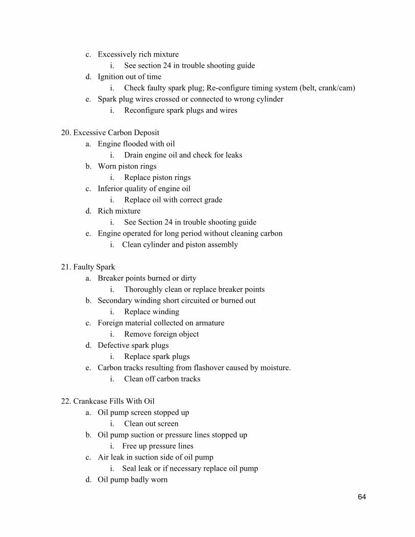
7.3 Troubleshooting Common Issues[27]
*Disclaimer Some issues involve parts outside the engine*
1. Engine Failure to Start a. Lack of fuel
i. Add fuel b. Ignition switch off
i. Turn ignition switch on c. Incorrect throttle setting
i. Adjust throttle d. Cold oil
i. Take care to properly store engine in cold temperatures; wait for oil to warm up; if necessary improve to grade with lower or wider operating temperature range
e. Defective battery (battery ignition systems) i. Replace battery
f. Dirty or defective spark plugs i. Replace spark
g. Wet ignition harness i. Let dry, and replace if damaged
h. Wrong grade of fuel i. Replace with 87Octane fuel
i. Spark advance retarded too far i. Check spark plug & wiring for issues; replace/reconfigure spark plug
and/or wiring j. Defective ignition wiring
i. Replace wiring k. Incorrect valve and/or ignition timing
i. Adjust timing belt or camshaft l. Incorrect valve clearance
i. Adjust tappets to increase or decrease the valve clearance
54

m. Broken Fuel Injector i. Replace fuel injector
n. Intake manifold air leaks i. Seal leaks or replace manifold
o. Broken, shredded or defective camshaft i. Replace with new camshaft
p. Spark plug wires crossed i. Rearrange spark plugs and wires
2. Low Power and Uneven Running
a. Mixture too rich or too lean i. See Section 24 in trouble shooting guide
b. Leaks in induction system i. Seal leaks
c. Defective or fouled spark plugs and loose plug connections i. Check for plug connections and/or replace spark plugs
d. Improper fuel grades i. Replace with 87Octane fuel
e. Wet or defective ignition wiring i. Wait for wiring to dry; may need to take to a mechanic
f. Engine overheating i. Replace coolant; may need a new radiator
g. Improper valve and/or ignition timing i. Adjust timing belt, crankshaft, and camshaft
h. Cracked engine mount or loose mount bolts i. Replace mount if cracked; If loose bolts tighten bolts
i. Foreign matter in induction system or fuel lines i. Remove matter
j. Fuel feed valve leaking or not operating properly i. Replace valve
k. Warped or burned valves or valve seats i. Replace valves
l. Broken valve springs i. Replace valve springs
m. Worn or sticking pistons or cylinders i. Replace piston or cylinder, and/or add lubrication
n. Cracked pistons or cylinders i. Replace cracked part
o. Cylinder gaskets blown
55

i. Replace gasket gasket p. Fuel Injector Icing
i. Let engine run and warm up q. Defective rocker arms or bearings
i. Replace defective part r. Bent crankshaft
i. Replace crankshaft s. Spark plug wires crossed
i. Reconfigure spark plugs & wires
3. High Oil Temperature a. 1. Insufficient oil supply
i. Add oil b. Defective oil temperature gauge
i. Replace gauge c. Airflow through oil cooler blocked
i. Turn off & let engine cool to then remove obstruction d. Overheated bearings
i. Turn off & let engine cool to then remove obstruction e. Dirty or improper grade of oil
i. Replace with proper grade oil f. Improper grade of fuel
i. Replace with 87Octane fuel g. Improper ignition timing
i. Adjust timing belt, crankshaft, and camshaft h. Main bearing shifting in crankcase bearing bore
i. Tighten bearings
4. Excess Oil Consumption a. Improper grade of oil
i. Replace with proper grade oil b. Piston rings worn, broken or incorrectly installed
i. Reinstall new piston rings c. Cracked pistons
i. Replace pistons d. Piston oil drain holes clogged
i. Clear holes e. Oil pressure too high
i. Adjust oil pump
56

f. Too much clearance between intake valve and guide i. Adjust valve position
5. Low Oil Pressure a. Insufficient oil supply
i. Add oil b. Foreign matter in relief valve
i. Remove foreign matter c. Defective pressure gauge, or clogged gauge line
i. Replace or clean clogged line or replace pressure gague d. Improper grade of oil
i. Replace with proper grade oil e. High oil temperature
i. See Section 3 in trouble shooting guide f. Oil Leak
i. Seal source of leakage g. Oil congealed in intake line
i. Clear intake line h. Excessively diluted oil
i. Replace oil i. Broken oil line
i. Replace line j. Excessive bearing clearance or wrong undersize bearings
i. Readjust or replace bearings k. Crankshaft plugs leaking or missing
i. Replace the plugs l. Worn oil pump gears
i. Replace gears or oil pump m. Broken oil pump gears
i. Replace oil pump
6. High Oil Pressure a. Improper grade of oil
i. Replace with proper grade oil b. Oil cold or frozen
i. Take care to properly store engine in cold temperatures; wait for oil to warm up; if necessary improve to grade with better temperature range
c. Oil channels clogged/crushed i. Clear clog or replace part with constricted channel
d. Defective pressure gauge
57

i. Replace pressure gauge e. Insufficient bearing clearance
i. Reconfigure or replace bearing f. Bearing tight due to engine overheating
i. See Section 13 in trouble shooting guide to fix overheating or replace bearing
7. Improper Engine Acceleration
a. Incorrectly adjusted fuel injectors i. Readjust or replace fuel injectors
b. Cold oil i. Take care to properly store engine in cold temperatures; wait for oil to
warm up; if necessary improve to grade with better temperature range c. Defective tachometer
i. Replace with new tachometer d. Fuel valve leaking or not operating properly
i. Replace valve e. Improper spark adjustment
i. Reconfigure spark plugs and wiring f. Improper engine timing
i. Adjust timing belt, crankshaft, and camshaft g. Air leaks or restriction in induction system
i. Seal leaks
8. Failure of Engine to Idle Properly a. Loose spark plug connectors
i. Adjust connectors b. Defective ignition harness
i. Replace harness c. Improper grade of fuel
i. Replace with 87Octane fuel d. Air leaks in induction system
i. Seal leaks e. Vapor in fuel system
i. Increase pressure from fuel pump f. Improper fuel pressure
i. Increase pressure from fuel pump g. Internal fuel injector trouble
i. Replace fuel injector
58

h. Partial obstruction in fuel lines i. Remove obstruction
i. Fuel valve leaking or not operating properly i. Replace valve
j. Improper valve clearance i. Adjust tappets to increase or decrease the valve clearance
k. Low cylinder compression i. Check cylinder leak; reposition crankshaft, piston head, & connecting rod
9. Failure of engine to Develop Full Power
a. Mixture too lean or too rich i. See Section 24 in trouble shooting guide
b. Improper grade of fuel i. Replace with 87Octane fuel
c. Incorrect fuel pressure i. Adjust fuel pump
d. Improper valve clearance i. Adjust tappets to increase or decrease the valve clearance
e. Improper grade of oil i. Replace with proper grade oil
f. Oil too hot or too cold i. See section 3 in trouble shooting guide or change grade of oil
g. Rocker arms not properly lubricated i. Add lubrication to rocker arms
h. Incorrect valve or ignition timing i. Adjust timing belt, crankshaft, and camshaft
i. Defective spark plugs i. Replace spark plugs
j. Excessive carbon and pre‐ignition i. See Sections 19 and 20 in trouble shooting guide
k. Intake manifold too cold i. Let engine run and warm up
l. Weak or broken valve springs i. Replace valve springs
m. Low cylinder compression i. Check cylinder leak; reposition crankshaft, piston head, & connecting rod
n. Valve seats scored or worn i. Replace valve seating
o. Excessive back pressure from exhaust manifold
59

i. Check for bends and obstructions; Remove obstructions or replace part p. Engine stiff or tight
i. Add more oil q. Engine overheating
i. See Section 13 in trouble shooting guide r. Fuel Injector icing
i. Let engine run and warm up
10. Engine Stops a. Out of fuel
i. Add fuel b. Fuel lines partially obstructed
i. Remove obstruction c. Foreign object in induction system
i. Remove foreign object d. Water in fuel
i. Remove fuel, let dry, and temporarily replace with high octane fuel e. Broken fuel lines
i. Replace fuel lines f. Sheared timing gears
i. Replace timing gears g. Internal structural failure
i. Replace shortblock h. Air vent or fuel tank obstructed
i. Remove obstruction
11. Engine Vibrates Excessively a. Bent crankshaft
i. Replace crankshaft b. Unequal valve clearance
i. Adjust tappets to increase or decrease the valve clearance c. Defective spark plugs
i. Replace spark Plugs d. Engine loose on mount
i. Tighten engine bolts e. Fuel Injector icing
i. Let engine run and warm up f. Improper ignition timing
i. Adjust timing belt, crankshaft, and camshaft
60

12. Engine Continually Throws Alternator Belt
a. Bent pulley i. Replace Pulley
b. Worn dynamic damper bushings or pins i. Replace bushings and/or pins
13. Engine Overheats
a. Retarded spark or spark timed late i. Check spark plug & wiring for issues; replace/reconfigure spark plug
and/or wiring b. Defective oil circulation
i. Check for issues in lubrication channels and possibly replace oil pump c. Thin oil
i. Change to proper grade oil d. Lean Mixture
i. See Section 24 in trouble shooting guide e. Camshaft out of time
i. Realign camshaft f. Idling engine too long
i. Turn engine off and let cool g. Insufficient oil cooling
i. See Section 3 in trouble shooting guide h. Insufficient oil supply
i. Add more oil i. Excessive carbon buildup
i. See Section 20 in trouble shooting guide j. Overheated bearing
i. Turn engine off and wait to cool k. Tight bearings or pistons out of line
i. Realign pistons and tighten bearings
14. High Cylinder Head Temperature a. Mixture too lean
i. See Section 24 in trouble shooting guide b. Improper grade of fuel
i. Replace with 87Octane fuel c. Air leaks in induction system
i. Seal leaks
61

d. Damaged cylinder fins i. Reinstall new fins
e. Incorrect valve operation or clearance i. Reconfigure valvetrain
f. Restrictions in exhaust system i. Search for bends & obstructions; remove obstructions & replace any
bent/broken parts g. Spark retarded
i. Check spark plug & wiring for issues; replace/reconfigure spark plug and/or wiring
h. Pre‐ignition through carbon or defective spark plugs i. Clean cylinder or replace spark plugs
i. Warped valves i. Replace valves
j. Loose valve seats and guides i. Readjust valve seats and guides
k. Worn valve guides i. Replace valve guides
15. Engine Won’t Stop When Switch is Turned off
a. Engine excessively hot i. See Section 13 in trouble shooting guide
b. Incandescent carbon in cylinders i. See Section 20 in trouble shooting guide
16. Engine Misses Intermittently
a. Fouled spark plug i. Replace spark plug
b. Defective spark plug i. Replace spark plug
c. Broken or grounded spark plug wire i. Replace spark plug wire
d. Improper valve clearance i. Adjust tappets to increase or decrease the valve clearance
e. Low compression on one or more cylinders i. Check cylinder leak; reposition crankshaft, piston head, & connecting rod
17. Engine Misses Regularly
a. Lean mixture
62

i. See section 24 in trouble shooting guide b. Rich mixture
i. See section 24 in trouble shooting guide c. Water in gasoline
i. Remove fuel, let dry, and temporarily replace with high octane fuel d. Air leak in intake manifold
i. Seal leak if possible or replace e. Intake valve holding open
i. Ensure oil level is sufficient and directly lubricate valve assembly f. Sticky valve guides
i. Ensure oil level is sufficient and directly lubricate valve assembly g. Weak valve springs
i. Replace valve springs h. Faulty spark
i. Replace spark plug
18. Cylinder Misses a. Short circuited spark plugs
i. Replace with new spark plugs b. Short circuited spark plug wire
i. Replace with new wire c. Spark plug gap too wide
i. Have mechanic reseat spark plugs d. Weak exhaust valve springs
i. Replace weak valve springs e. Insufficient valve tappet clearance
i. Reposition valvetrain f. Wrong spark plug gap
i. Reseat spark plugs g. Weak compression
i. Check cylinder leak; reposition crankshaft, piston head, & connecting rod h. Air leak around intake valve stem
i. Take to mechanic; may need to replace valves or cylinder head
19. Preignition a. Carbon Buildup
i. See Section 20 in trouble shooting guide b. Overheating
i. See Section 13 in trouble shooting guide
63
c. Excessively rich mixture i. See section 24 in trouble shooting guide
d. Ignition out of time i. Check faulty spark plug; Reconfigure timing system (belt, crank/cam)
e. Spark plug wires crossed or connected to wrong cylinder i. Reconfigure spark plugs and wires
20. Excessive Carbon Deposit
a. Engine flooded with oil i. Drain engine oil and check for leaks
b. Worn piston rings i. Replace piston rings
c. Inferior quality of engine oil i. Replace oil with correct grade
d. Rich mixture i. See Section 24 in trouble shooting guide
e. Engine operated for long period without cleaning carbon i. Clean cylinder and piston assembly
21. Faulty Spark
a. Breaker points burned or dirty i. Thoroughly clean or replace breaker points
b. Secondary winding short circuited or burned out i. Replace winding
c. Foreign material collected on armature i. Remove foreign object
d. Defective spark plugs i. Replace spark plugs
e. Carbon tracks resulting from flashover caused by moisture. i. Clean off carbon tracks
22. Crankcase Fills With Oil
a. Oil pump screen stopped up i. Clean out screen
b. Oil pump suction or pressure lines stopped up i. Free up pressure lines
c. Air leak in suction side of oil pump i. Seal leak or if necessary replace oil pump
d. Oil pump badly worn
64

i. Replace pump
23. Engine Pumps Oil a. Piston rings poor fit in piston grooves
i. Replace with new piston rings b. Piston rings poor fit in cylinder
i. Replace with new piston rings c. Broken piston rings
i. Replace with new piston rings d. Scored cylinder walls
i. Replace cylinder liner e. Excessive piston clearance
i. Replace cylinder seal f. Excessive oil pressure
i. Adjust pressure from oil pump g. Thin oil
i. Replace oil h. Improper grade of oil
i. Replace with proper grade oil i. Excessive bearing clearance
i. Replace bearings j. Faulty oil pump
i. Replace pump
24. Fuel Mixture Inspection a. Proper Mixture: Quick blue flame without yellow tip.
b. Rich Mixture: Long deep blue flame with red tip, black smoke.
i. High fuel pressure 1. Adjust fuel pump
ii. Oil in cylinders 1. May be too much oil in crankcase; make sure the engine has the
proper amount of oil iii. Fuel Injector seating improperly
1. Take to mechanic to get injector reseated
c. Lean Mixture: Short irregular light blue flame with yellow tip. i. Insufficient fuel in tank
1. Add more fuel
65

ii. Partially clogged fuel line 1. Check for debris and unclog or replace fuel line
iii. Insufficient air pressure in pressure fuel tank 1. Replace fuel pump
iv. Sticking valves 1. Ensure oil level is sufficient and directly lubricate valve assembly
d. Oil pumping is shown by blue exhaust smoke.
66

8. Failure Modes and Effects Analysis (FMEA) All parts of the RumbleBug 1500 were subjected to FMEA. This was to ensure that our team understood how the engine ran and to show what parts were most likely to fail. Figure 8.1 below shows the FMEA completed for the Crankshaft. Appendix 4 lists all FMEA completed by part numbers. Each FMEA follows the same format found below.
Figure 8.1
The FMEA chart is organized by columns, each of which are described below:
Column one lists a function of the part being analized. Column two lists in what ways the part can fail to meet the function stated in the first
column. Column three lists how this failure mode will affect the engine. Column four lists potential causes for the failure mode. Column five lists the outward signs of the failure mode or how the failure could be
detected. Column six ranks the severity of the failure mode from 1 to 5 with 5 being the most
severe. A five ranking would have potential harm to the user. Column seven ranks the rate of occurrence of the failure mode from occurring from 1 to 5
with 5 being the very likely to occur. Column eight ranks the ease of detecting the failure mode from 1 to 5 with 5 being near
impossible to detect. Column nine calculates the risk priority number (RPN) of the failure mode. The RPN
helps direct focus to the most important failure modes.
67

Column ten recommends corrective actions. These actions are potential methods to reduce the RPN value.
Column eleven reranks the severity considering the implementation of the recommended corrective actions.
Column twelve reranks the rate of occurrence considering the implementation of the recommended corrective actions.
Column thirteen reranks the ease of detection considering the implementation of the recommended corrective actions.
Column fourteen recalculates the RPN value considering the implementation of the recommended corrective actions.
Using this method, our team can focus on the failure modes that are most important and implement the correct actions to ensure a smoothly running motorcycle engine. 9. Final Cost Estimate The final cost estimate for our engine summed up to be $2,943.67 for one unit. This amount represents the cost required from us to manufacture one engine and not the price for the consumer to purchase. This cost was derived from three different sections: Purchased Parts, Manufactured Parts and Tools. Overhead Expenses could also be considered in marking up the price for the end user, but this is outside of the scope of this project. The manufacturers that we will work with include:
1. ARP for the connecting rod bolts 2. Crower for exhaust valve springs and intake valves springs 3. Auto Parts Warehouse for the head bolts, rocker arm, the throttle body assembly,
the starter, dipstick, fuel injectors, ignition coils, spark plug wires, alternator, and the oil pump
4. Advanced Auto Parts for spark plugs, tensioner pulley, and the timing belt 5. J&P Cycles for valve keepers [26]
Purchased parts have a set price from their manufacturers. The breakdown of the costs for each part can be viewed in our Bill of Materials in section 5.3. To estimate the cost of our manufactured parts, we used CES EduPack and Solidworks. CES EduPack assisted us in picking the appropriate material for each part. In addition, CES EduPack gave us an estimate of the material cost per pound. From Solidworks we obtained the weight of each part and calculated the price of the rough material to produce the part. We took the manufacturing cost of the part into account to come up with our final estimate.
68

Category Brief Description Cost
Purchased Parts Parts bought from outside suppliers $1,158.21
Manufactured Parts Parts that will be made in house $1,265.46
Labor Cost of labor at $65/hr for 8 hours $520.00
Total Price $2,943.67
The following table summarizes the tooling cost, which mainly includes the dies for our die cast parts. The breakdown of those costs can be viewed under the BOM. It is important to note that the tooling cost is a one time expense that we are going to invest in the beginning of the project. The dies and related tools were estimated for each part using custompartnet.com.[15]
Category Brief Description Cost
Tools Cost of tools needed to start production $31,902.00
10. Design Satisfies Requirements The following table, Table 10.1, serves to summarize each of the derived and assigned requirements for this project:
Requirement Value Derived/Assigned Satisfied? RumbleBug 1500
Number of cylinders, strokes
2 or more cylinders, 4 stroke cycle
Assigned Yes Inline 4 Engine, Otto Cycle
Displacement 15001800cc Assigned Yes 1500cc
Compression Ratio
9:110:1 Assigned Yes 10:1
Transmission powers 6speed
Assigned Yes
Horsepower 100150 HP at 5000 RPM
Derived No 75 HP at 1500 RPM
Fuel Economy 3540 MPG Derived Exceeded Up to 42 MPG
69

Cost to Consumer
$8,000 $10,000
Derived Yes Manufacturing cost: $2,943.67
Emissions <0.8 g/km HC+NOx
Derived Yes Achievable with a 3way catalytic converter
Emissions <12 g/km CO Derived Yes Achievable with a 3way catalytic converter
Weight <300 lbs dry Derived Yes 225 lbs. dry
Lifespan >60,000 miles w/ regular maintenance
Derived More testing required
Table 10.1 Assigned requirements:
The team was instructed to create an engine with at least two cylinders that operate on a
four stroke cycle. The engine is required to have a displacement of between 1500cc and 1800cc
and a compression ratio between 9 and 10. It must be capable of 5000 rpm continuous service
and 800 rpm when idling, and it must power a 6 speed transmission. The RumbleBug 1500 is an
inlinestyle engine that has four cylinders. It operates on a four stroke Otto cycle. Each cylinder
displaces 375cc giving the RumbleBug 1500 a total displacement of 1500cc. It has a
compression ratio of 10:1 and powers a 6speed transmission.
Derived Requirements:
The team wanted the engine to have between 100 and 150 HP at 5,000 RPM. They also
wanted to achieve 3540 MPG and follow all EPA emissions standards. Goals were set to keep
the cost to the consumer below $10,000 and to keep the dry weight of the engine below 300 lbs.
The RumbleBug 1500 only achieves a maximum horsepower of 75 at 5,000 RPM; however, all
other requirements are met or exceeded. Using a 3way catalytic converter, the engine meets all
emissions requirements. The estimated cost to manufacture the engine is only $2,943.67.
Therefore, it is reasonable to assume that the cost to consumer will be less than $10,000. The dry
70

weight of the RumbleBug 1500 is only 225 lbs and the fuel efficiency exceeds the original goal
with a maximum of 42 MPG.
11. Project Management
11.1 Work Breakdown Structure
During the conceptual phase of the project, the team collaborated as a whole on reports
and deliverables. Group meetings would involve the entire team, with each member contributing
their thoughts into the deliverable due. The final product would be scribed by individual team
members expressing their ideas, with the group providing edits, corrections, and transitions from
one section to the next.
During the design phase of the project, the team was split into subgroups, with each
group responsible for a predetermined subassembly of the engine. Group 1, consisting of Joanna
Rumbley, Masihuddin Ahmed, Matthew Kaiser, and Theodore Leung, was responsible for the
engine block subassembly, which included the crankshaft, connecting rods, pistons, wrist pins,
and flywheel. Group 2, consisting of Spencer Boyd, Stephen Finnegan, and Kevin Miller, was
responsible for the cylinder head subassembly, which included the exhaust valves, intake valves,
camshaft, and rocker arm. Group 3, consisting of Carly Harris, Jonathan Shabtai, and Anthony
Spalding, was responsible for the oil pan, timing belt, fuel injectors, ignition components, and oil
pump. Each group assigned individual parts to individual members. The individual would be
responsible for modeling the parts they were assigned and converting the models into blueprint
drawings. All parts were shared over Solidworks PDM® software, and the final assembly was
compiled by Kevin Miller.
During the final phase of the project, the team collaborated as a whole on larger
deliverables that involved multiple subassemblies such as the theory of operations and the final
presentation. Like the conceptual phase, individual team members would express their ideas in
the deliverable, and the group as a whole would provide edits, corrections, and transitions.
71

Subgroup work was still present, as the subassemblies continued to be modeled, dimensioned,
and compiled.
11.2 Team Contributions
Joanna Rumbley:
I was the team lead and a member of group one, which focused on the crankcase assembly. I
assigned team member roles according to each individual’s skills and organized when and how
tasks should be done. Throughout the semester, I scheduled team meetings and made sure that
everyone had something to work on. Good communication was also one thing I focused on every
week. When group presentations and this final paper were started, I helped everyone be clear on
aspects such as formatting and what each person was in charge of. My individual work included
making several CAD models and drawings and the cost analysis for manufactured parts. I also
contributed to the team by researching parts of an engine, working with others on the FMEA, and
proofreading this paper to ensure all the information was consistent.
Teddy Leung:
I was a member of group one. Our group was in charge of designing the crankcase subassembly.
Personally, I was in charge of designing the connecting rod bolts, wrist pins, and flywheel. I also
assisted with general research into engine mechanics, market prices of various parts, and make or
buy decisions. Lastly, I contributed to group one’s portion of the FMEA.
Spencer Boyd:
I was a member of group two. In addition, I was our project manager to help manage and
organize with our team lead Joanna. Our group primarily focused on the valvetrain assembly
components. For our group, I helped research and select materials and manufacturing methods
for various parts such as the valves and camshaft. After all of the groups researched the desired
specifications, I was one of the leads for finding suppliers for all of the purchased parts. For
CAD I helped find preexisting Solidworks drawings for purchased parts such as the dipstick and
72

fuel injector. I had also written the theory of operations while helping others with various small
tasks.
Tony Spalding:
I was a member of group three. Our group was in charge of designing and finding existing CAD
models for miscellaneous subassemblies and parts that did not fit with the two major assemblies
the other groups worked with. Personally, I was in charge of designing the oil pan and oil filter
adaptor, while also finding models for the timing belt, alternator, water pump, oil pump, and
tensioner pulley. In terms of small groups, I was an unofficial leader for group three as I was
primarily the person that set up meetings and took minutes. I also helped with general research to
help my group understand how an engine works, and how the parts that our group needed to
design work. I took primary responsibility for the product design specification and I also
designed our logo.
Jonathan Shabtai
I was a member of group three. Our group was in charge of designing various components for
the engine including the oil pan and intake and exhaust manifolds. We also obtained CAD
models for the starter, ignition plugs and other miscellaneous parts. I was in charge of designing
the exhaust manifold and the timing sprocket. In addition, I helped choosing the materials for our
parts and assisted in deciding on the manufacturing methods that we will use. For this paper, I
was in charge of the final costing section. This included estimating the cost of tools for the whole
project, going over the costing for each manufactured part and making sure all of the prices for
the purchased parts are correctly marked in the BOM.
Carly Harris:
I was a member of group three. Our group focused on miscellaneous components of the engine
that did not fit with the assemblies assigned to groups one and two. I was in charge of designing
the intake manifold, as well as the throttle body assembly and finding models for purchased parts
including the timing cover, spark plugs, ignition coils, and spark plug wires. I also contributed
73

significantly to materials selection for group three as well as costing. For this paper, I was in
charge of compiling and approving materials and manufacturing methods for all components as
well as organizational components including nomenclature, and the table of contents. I also
wrote the goals and objectives section and helped in editing and proofreading all sections of the
paper.
Masihuddin Ahmed:
I was a member of group one. Our group was in charge of designing the crankcase subassembly.
Personally, I was in charge of designing the crankshaft and pistons. I also assisted with general
research into engine mechanics, market prices of various parts, and make or buy decisions, and
FMEA. Lastly, I developed the manufacturing plan’s quality control procedure and completed
costing estimates.
Matthew Kaiser
I was a member of group one. I was in charge of modeling the thermodynamics of the engine. I
created a one dimensional model in MATLAB, which took into account variations of specific
heats, fuel to air ratio, volumetric efficiency, bore to stroke ratio, heat transfer due to cooling,
friction due to bearings and pumping losses, varying combustion timing, and length of the
connecting rods. I also did the cooling calculations, as well as the bearing calculations, and I
calculated the fuel economy and emissions data.
Stephen Finnegan
I was a member of group two. Our group was in charge of the cylinder head and the valvetrain
components. I helped research combustion chamber geometry, looking into how best to have the
combustion chamber and valves integrate. I also helped with the emissions calculations. For
CAD, the only manufacturing part I was responsible for was the cylinder head and valves. I took
responsibility of the FMEA of our parts.
Kevin Miller
74

I was a member of group 2, which focused on the cylinder head and valvetrain components. I
helped research valve and cam design. I was in charge of modeling the camshaft, rockers and
integrating the valvetrain and cylinder head. I was also in charge of assembly of full engine,
ensuring that each of the components fit together properly. My experience with solidworks
allowed me to help other members of our team with their solid modelling.
11.3 Final Gantt Chart
Figure 11.3 shows the final Gantt chart. The urgency of the tasks are colorcoded in
yelloworangered, where red is the most urgent. The purple blocks represent the float time. The
light red bar marks the last week of the project, week 14.
Figure 11.3 Final Gantt Chart
75

12. Acknowledgements We would like to acknowledge Dr. Sunniva Collins for providing helpful resources and feedback
for our project. We would also like to acknowledge the teaching assistants Jon Sasson, Matt
Holdren, Mustafa Unal, and Yunus Alapan for providing feedback on our project presentations
and being available to answer any questions we had.
76

13. References [1] 4JB1TC Engine: Mechanical Specification and Structure. N.p.: Isuzu Motors Limited, n.d.
Print.
[2] "Accel A35150115 Fuel Injector." Auto Parts Warehouse. Auto Parts Warehouse, 2015.
Web. 09 Dec. 2015.
<http://www.autopartswarehouse.com/sku/Accel/Fuel_Injector/A35150115.html>.
[3] Bahrami, M. "Forced Convection Heat Transfer." (n.d.): n. pag. SFU. Simon Fraser
University (SFU). Web. 8 Dec. 2015.
<http://www.sfu.ca/~mbahrami/ENSC%20388/Notes/Forced%20Convection.pdf>.
[4] Bahrami, M. "Natural Convection." (2006): n. pag. SFU. Simon Fraser University (SFU).
Web. 8 Dec. 2015.
<http://www.sfu.ca/~mbahrami/ENSC%20388/Notes/Natural%20Convection.pdf>.
[5] "Comparing Naturally Cooled Horizontal Baseplate Heat Sinks with Vertical Baseplate Heat
Sinks." (n.d.): n. pag. Thermal Software. Thermal Solutions Inc. Web. 8 Dec. 2015.
<http://www.thermalsoftware.com/vert_vs_horz_sink.pdf>.
[6] "Critical Characteristics and Key Product Characteristics (KC)." N.p., Aug. 2003. Web. 10
Dec. 2015. <https://www.sae.org/iaqg/publications/as9103whitepaper.doc>.
[7] "Dyno Testing What It Means." Dyno Testing What It Means. Smeding Performance, n.d.
Web. 10 Dec. 2015.
[8] "Engine Blowby." Engine Blowby. AA1Car, n.d. Web. 10 Dec. 2015.
77

[9]"EPA Finalizes Emission Standards for New Highway Motorcycles."Motorcycles | OnRoad
Vehicles and Engines | US EPA. United States Environmental Protection Agency, Dec.
2003. Web. 09 Dec. 2015. <http://www3.epa.gov/otaq/regs/roadbike/420f03044.pdf>.
[10] Heywood, John B. Internal Combustion Engine Fundamentals. New York: McGrawHill,
1988. Print.
[11] Hoag, Kevin L. Vehicular Engine Design. Wien: Springer, 2006. Print.
[12] Honda CBX: Shop Manual. Tokyo: Honda Motor, 1979. Print.
[13] Juvinall, Robert C., and Kurt M. Marshek. Fundamentals of Machine Component Design.
5th ed. N.p.: John Wiley & Sons, 2012. Print.
[14] Kumruoğlu, Levent Cenk. "Mechanical and Microstructure Properties of Chilled Cast Iron
Camshaft: Experimental and Computer Aided Evaluation." Materials & Design 30.4
(2009): 92738. Science Direct. Web. 10 Dec. 2015.
[15]"Manufacturing Cost Estimation." Manufacturing Cost Estimation. CustomPartNet, 2009.
Web. 9 Nov. 2015. <http://www.custompartnet.com/>.
[16] Moon, Clyde H. Cam Design: A Manual for Engineers, Designers and Draftsmen.
Farmington, Ct.: AMCAM, 1962. Print.
[17] "Motorcycle Noise Limits." AAA Digest of Motor Laws. American Automobile Association,
2015. Web. 30 Nov. 2015. <http://drivinglaws.aaa.com/tag/motorcyclenoiselimits/>.
[18]"MOTORCYCLE TRANSPORTATION FACT SHEET." Ride to Work. N.p., n.d. Web. 09
Dec. 2015. <http://www.ridetowork.org/files/docs/Trans_Facts.html>.
[19] Pulkrabek, W. W. Engineering Fundamentals of the Internal Combustion Engine. United
States of America: Prentice Hall, 2004. Print.
78

[20] "Quality Control for Remanufactured Engines and Parts | A&P Auto Parts."Quality Control.
A&P Auto Parts, 23 Sept. 2013. Web. 10 Dec. 2015.
[21] Spakovszky, Z. S. "18.2 Heat Transfer From a Fin." Thermodynamics and Propulsion. Ed.
D. Quattrochi. Massachusetts Institute of Technology (MIT), n.d. Web. 09 Dec. 2015.
<http://web.mit.edu/16.unified/www/FALL/thermodynamics/notes/node128.html>.
[22] Stone, Richard. Introduction to Internal Combustion Engines. Basingstoke: Macmillan,
1992. Print.
[23] "Tech Tip: Don’t ‘Blow By’ PCV Inspections." Underhood Service. Babcox Media, Inc,
2015. Web. 10 Dec. 2015.
[24] "Transportation." Powertrain Final Test. ATS Automation, 2015. Web. 10 Dec. 2015.
[25] Wunderlich, Wilfried, and Morihito Hayashi. "Thermal Cyclic Fatigue Analysis of Three
Aluminum Piston Alloys." International Journal of Material and Mechanical
Engineering 1.3 (2012): 5760. Print.
[26] "Valve Keepers | 433108." J&P Cycles. N.p., 2015. Web. 06 Dec. 2015.
<http://www.jpcycles.com/product/433108?utm_source=none&utm_term=%5
B74945730610%3Aproduct_type_l1%3D%3Dvehicles%2520%26%2520parts%26%
2520product_type_l2%3D%3Dland%2520vehicles%26%2520product_type_l3%3D%
3Dmot&cid=Google%2BSEARCH%2BNONBRAND%2BPLA%2B%2BShopping%
2BCampaign&adpos=1o1&creative=42040093810&device=c&matchtype=&network=
g&gclid=CPiJlIKCyMkCFYU9aQodAAcNJg>.
[27] "Engine Trouble Shooting Guide." (n.d.): n. pag. Web. 10 Dec. 2015.
<http://eci.aero/pdf/EngineTroubleShootingGuide.pdf>.
79

13. Appendix A.1 Team Charter 1. Purpose
Our team’s purpose is to design a motorcycle engine that is durable, reliable and meets
specific requirements, which are stated later in the Scope section. At the end of our given time
period, we anticipate presenting a completed and feasible engine design that will be marketable
to customers and profitable for the company.
2. Background
Our team is working to support the Spartan Motorcycle Company by designing the
engine for their new motorcycle model planned for release in 2017. The team is a subdivision of
the research and development department for the company and is focused solely on engine
design. The customers of this project are motorcycle enthusiasts who want a new bike with
cutting edge design and features. Stakeholders include the company’s suppliers, investors,
customers, and management. We estimate that the cost of acquisition for this engine design over
the life cycle per engine will be below $10,000. This design project has a relatively close
deadline so our team will need to complete our design in an accelerated time frame while still
achieving all requirements specified by management.
3. Scope
Our team aims to design a motorcycle engine that meets the following requirements:
2 or more cylinders, 4stroke cycle
80

Displacement 1500 to 1800cc
Fuel injection, spark ignition
Runs on standard gasoline
Compression ratio 9:1 to 10:1
Capable of 5000 rpm continuous service, idle at 800 rpm
Powers a sixspeed transmission
Our design will include mechanical drawings, suggested manufacturing processes,
materials, heat treatments (if applicable), and manufacturing cost. In addition to a detailed
design, we will cover technical specifications, a theory of operations, a risk analysis, an FMEA
chart, and a bill of materials.
Our engine must pass all state and federal safety regulations along with any other tests
the Spartan Motorcycle Company deems necessary.
Our design team will work to create the best product possible while continually keeping
in mind the following throughout our design process:
Manufacturability
Cost
Environmental Impact
Marketability
4. Team composition
The team consists of ten full time members representing the engine design subdivision of
the Spartan Motorcycle Company and one advisor overseeing the project. One semester (3.5
81

months) will be dedicated to the project with weekly progress reports delivered to the advisor.
The team will have a minimum of one meeting per week and subgroups will meet as needed.
5. Membership roles
Masihuddin Ahmed: Contact Info: 7742102167, [email protected] Role: Requirements Lead
Spencer Boyd: Contact Info: 3307038183, [email protected] Role: Project Manager
Stephen Finnegan: Contact Info: 4402580643, [email protected] Role: Standards Manager
Carly Harris: Contact Info: 4128558727, [email protected] Role: Material Selection Expert
Matthew Kaiser: Contact Info: 7132083336, [email protected] Role: Thermodynamics Expert
Theodore “Teddy” Leung: Contact Info: 2818394710, [email protected] Role: Competitive Engineering Manager
Kevin Miller: Contact Info: 9375431776, [email protected] Role: Engine Evaluation Expert
Joanna Rumbley: Contact Info: 7209859919, [email protected] Role: Team Lead
Jonathan “Yoni” Shabtai: Contact Info: 2244001253, [email protected] Role: CFO (Chief Financial Officer)
Anthony “Tony” Spalding: Contact Info: 5742867788, [email protected] Role: System Integration Specialist
82

6. Team empowerment
The team claims unrestricted authority over all facets of engine design, including but not
limited to: aesthetics, financial decisions, physical dimensions, material selection, methods of
operation, etc. The team reserves the right to enact appropriate conflict resolution strategies
should conflict between team members arise. In the event of unsatisfactory leadership, the team
reserves the right to alter membership roles and responsibilities.
7. Team operations
The team will be split up into subgroups. Each subgroup will be responsible for a
specific part of the project. The whole group will meet on a weekly basis and the subgroups will
hold separate, additional meetings. Small scale decisions will be decided within the subgroups,
and major decisions will be brought up in the large group meetings. Furthermore, in the weekly
meetings every subgroup will present its progress in order to make sure the whole team is on
schedule and kept up to date. The team will operate with mutual respect and consideration of all
ideas. When multiple ideas are presented, a vote will be taken to determine which idea we will
use. In the event of a tie, the project lead will have the authority to choose which idea to proceed
with.
If a team member cannot perform his/her duties or decides to leave the project, his/her
roles will be delegated by the team lead to a different member or members. In addition, if a
member is interested in changing his/her responsibilities, he/she would have to set up a meeting
with the team lead and discuss a course of action.
83

8. Team Performance Assessment
Team member performance will be determined with regard to the following criteria:
Technical Knowledge
Contribution Level
Preparedness
Communication
Attitude
Meeting Attendance
9. Acquisition milestones and schedules
Our design team plans to meet the following timeline:
Date Task Completed
September 11 Present First Progress Report
September 14
Complete Team Charter Complete Project Plan Review Presentation
September 25 Present Second Progress Report
September 30 Present Third Progress Report
October 12 Concept Design Review
October 21 Present Fourth Progress Report
October 30 Present Fifth Progress Report
November 6 Present Sixth Progress Report
November 11 Present Seventh Progress Report
84

November 18 Present Eighth Progress Report
November 30 Present Design Review
December 7 Present Final Report
10. Signature Page
The below signatures represent each member’s acknowledgement of their participation in
this project and their responsibilities written herein.
Masihuddin Ahmed ______________________________________
Spencer Boyd ______________________________________
Stephen Finnegan ______________________________________
Carly Harris ______________________________________
Matthew Kaiser ______________________________________
Theodore (Teddy) Leung ______________________________________
Kevin Miller ______________________________________
Joanna Rumbley ______________________________________
Jonathan Shabtai ______________________________________
Anthony Spalding ______________________________________
11. Approval
85

This Charter, representing the group of Rumbley and The Rumblers, is hereby approved
with the below signature of Dr. Sunniva Collins, Professor of EMAE 360 Design and
Manufacturing II.
Dr. Sunniva Collins ______________________________________
A.2 Product Design Specification Product Identification
Product name: RumbleBug 1500 [related to the RumbleBug 1000 (1000 cc) and the RumbleBug 500 (500 cc)]
Basic functions: 4 stroke engine that displaces 1500 cc’s to power motorcycles produced by the Spartan Motorcycle Company
Special features: 4 Cylinders Inline Design Lightweight Design
Key performance targets: 3540 MPG fuel efficiency 1.2 Bore/Stroke Ratio Less than 300 lbs dry weight Target envelope (W x L x H): 18” x 30” x 23”
Service environment: Engine should not be operated at temperatures lower than 20° F Engine should be operated in dry environments only Engine should be stored in a dry place when not in use Engine should be strapped down and secured for transportation, if necessary Predictable misuse:
Improper storage Improperly performed maintenance
86

Any improper use of the motorcycle could be considered misuse of this product. Please consult your motorcycle manual.
User training required: This engine requires no special training to operate aside from standard motorcycle training. User should conduct maintenance at his/her own risk and always consult a mechanic if he/she encounters any problems.
Market Identification
Target Market: This engine is created for a cruiserstyle motorcycle. The target market includes many casual motorcycle riders who appreciate the design of classic bikes.
Anticipated market demand: Sales are expected to be 7,500 units for the first year, 12,000 units for the second year, and 15,000 units for the third year.
Competing products: Similar motorcycle engines that have close to 1500cc and are close in horsepower. Examples include the 1500cc Goldwing by Honda or the Triumph Thunderbird Storm which has 1699cc.
Logo:
“RumbleBug” is being trademarked by the Spartan Motorcycle Company legal team
Key Project Deadlines
Date Task Completed
October 12 Concept Design Review
87

October 21 Present Fourth Progress Report
October 30 Present Fifth Progress Report
November 6 Present Sixth Progress Report
November 11 Present Seventh Progress Report
November 18 Present Eighth Progress Report
November 30 Present Design Review
December 7 Present Final Report
Physical Description
Number of cylinders: 4 cylinders, 375cc per cylinder (1500cc total) Configuration: Inline 4 Combustion chamber geometry: Volume: ~42cc, Quench: 0.0050.0065”, Bore: 3.27” Bore/stroke ratio: 1.2 Operating cycle: Otto Cycle Target weight: <300 lbs dry Target envelope (W x L x H): 18” x 30” x 23”
Financial Requirements
Target Overall Cost: ~$5,000.00 per unit Target Manufacturing Cost: ~$4,000.00 per unit Warranty policy: Five years or twenty thousand miles
Social, Political, and Legal Requirements
Meets emission standard CFR ∮86.4102006 for motorcycles: 0.8 g/km HC + NOX and 12 g/km CO[9]
Meets Ohio state noise level requirement of 82 dB or below when traveling at 35 mph or less from 50 feet away and below 86 dB at more than 35 mph [17]
88
Manufacturing Specifications
Examples of parts and processes for inhouse manufacturing: Engine Block Die Casting Crankshaft CNC Machining Exhaust Valves Forging/Machining/Heat Treating Oil Pan Die Casting Pistons Die Casting/CNC Machining Intake Valves Forging/Machining/Heat Treating
Examples of purchased parts: Exhaust Valve Spring Fuel Injector Spark Plugs Timing Belt Starter Alternator
89

A.3 Pugh Charts
Figure A.3.1: Pugh Chart for selection of engine type. We decided on an inline 4.
Figure A.3.2: Pugh Chart for the selection of the bore/stroke ratio.
Figure A.3.3: Pugh Chart for the selection of the engine cooling system.
90

Figure A.3.4: Pugh Chart for the selection of the engine block material.
91

92

93

94

95

96

97

98

99

100

101

102
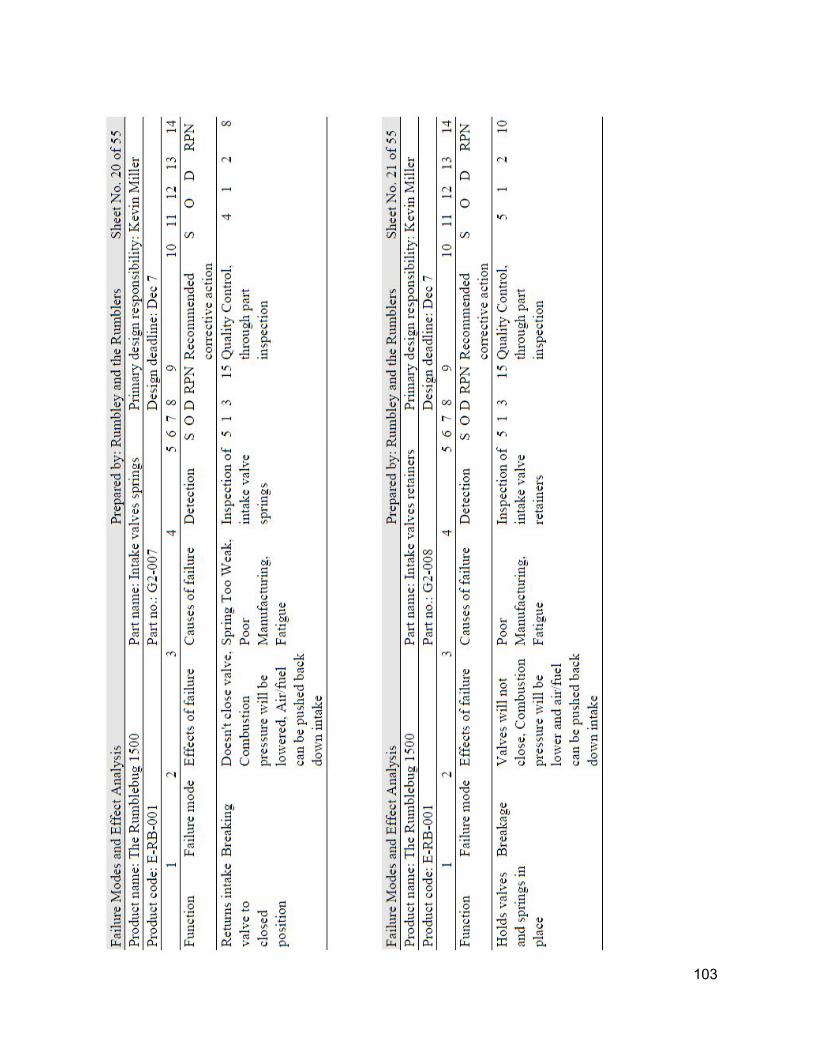
103

104

105
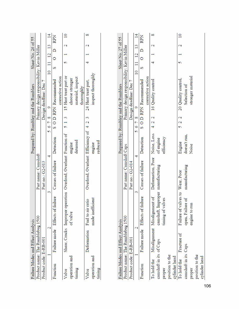
106

107

108

109

110

111

112

113

114

115

116

117

118

119

120

121

122

123

A.5 Calculations A.5.1 MATLAB code %programmed by mpk65 %2015 clc clear all clf %engine parameters throttle = 1; Disp = 1500; %total volume in cc N = 5000; %engine speed j = (N 200)/600; r_c = 10; %compression ratio cyl = 4; %number of cylinders b_s = 1.2; %bore to stroke ratio %assumptions AF = 12.5; %air to fuel ratio Qf = 44400; %kJ/kg lhv Ca0 = 0.933581512605042; %Cp parameter Ca1 = 0.000258727731092437; Ca2 = 5.11092436974791e08; Cb0 = 0.644240168067227; %Cv parameter Cb1 = 0.00026198974789916; Cb2 = 5.21899159663866e08; T0 = 298; %degrees Kke Vol_eff = (.7371 + .01698*j +.00348485*j2 0.000643939
*j3)*throttle; P0 = 101.325*Vol_eff; %kPa %derived stuffs cyl_disp = Disp/cyl; TDC = cyl_disp*(1/(r_c 1)); %top dead center volume BDC = cyl_disp + TDC; %bottom dead center volume B = (4/pi * cyl_disp * b_s) (1/3); %calculates the bore on
other parameters St = B / b_s; %stroke l = 1.5 * St; %con rod length
124

k0 = (Ca0 + Ca1*T0 + Ca2 * T02)/(Cb0 + Cb1*T0 + Cb2 * T02); %gamma at start
ts = 30/N; %calculates stroke time intervals = 1000; %number of iterations Ma = (Disp + TDC * cyl)*P0/(1000000*T0*0.287); M_tot = Ma +Ma/AF; Avg_vel = St/(100*ts); Duration = .5; a = 5; %combustion parameter m = 1; %combustion parameter for i = 1:(4*intervals) Ts(i) = 423; %cylinder wall temp, kelvins t(i) = i * (ts / intervals); %time theta(i) = t(i)*pi/ts; %angle of crank x(i) = St/2 * cos(theta(i))+sqrt((l)2(St/2)2*(sin(theta(i)))2)l+St/2; %position from TDC Vol(i) = TDC + pi/4*B2*x(i); %volume at time i Area(i) = ((B2)/2 * pi + B* pi*x(i))/10000; comb(intervals) = 0; Ex_m(2*intervals) = M_tot/4; In_m(3*intervals) = M_tot/40; if i == 1 T(i) = 333; P(i) = P0* (BDC / Vol(i))(k0); k(i) = (Ca0 + Ca1*T(i) + Ca2 * T(i)2)/(Cb0 + Cb1*T(i) +
Cb2 * T(i)2); Work = P(i) * (BDC Vol(i))/1000000; h(i) = (129.8* (P(i)/100).8)/((cyl_disp/1000000).06 *
T(i)0.4)*(Avg_vel +1.4); Q(i) = h(i)*Area(i)*(T(i)Ts(i))*ts/intervals/1000; elseif i > 1 && i < (intervals+1) T(i) = (T(i1) * (Vol(i1) / Vol(i))(k(i1) 1))
Q(i1)/(M_tot/4*(Ca0 + Ca1*T(i1) + Ca2 * T(i1)2));
P(i) = P(i1)*(T(i) / T(i1))(k(i1)/(k(i1)1)); k(i) = (Ca0 + Ca1*T(i) + Ca2 * T(i)2)/(Cb0 + Cb1*T(i) +
Cb2 * T(i)2);
125

Work = Work (P(i)+P(i1))/2 * (Vol(i1) Vol(i))/1000000;
h(i) = (129.8* (P(i)/100).8)/((cyl_disp/1000000).06 * T(i)0.4)*(Avg_vel +1.4);
Q(i) = h(i)*Area(i)*(T(i)Ts(i))*ts/intervals/1000; elseif i > (intervals) && i < (intervals +
round(Duration*intervals/pi)) comb(i) = (1 exp(a*(((theta(i)
pi)/Duration)(m+1)))); burnt = (Ma/4)/AF*Qf*(comb(i) comb(i1)); T(i) = T(i1) * (Vol(i1) / Vol(i))(k(i1) 1) +
burnt/((Ca0 + Ca1*T(i1) + Ca2 * T(i1)2)*(M_tot/4)) Q(i1)/(M_tot/4*(Ca0 + Ca1*T(i1) + Ca2 * T(i1)2));
P(i) = P(i1)*(T(i) / T(i1)); k(i) = (Ca0 + Ca1*T(i) + Ca2 * T(i)2)/(Cb0 + Cb1*T(i) +
Cb2 * T(i)2); Work = Work (P(i)+P(i1))/2 * (Vol(i1)
Vol(i))/1000000; h(i) = (129.8* (P(i)/100).8)/((cyl_disp/1000000).06 *
T(i)0.4)*(Avg_vel +1.4); Q(i) = h(i)*Area(i)*(T(i)Ts(i))*ts/intervals/1000; elseif i > (intervals + round(Duration*intervals/pi)1) && i
< (2* intervals + 1) T(i) = T(i1) * (Vol(i1) / Vol(i))(k(i1) 1)
Q(i1)/(M_tot/4*(Ca0 + Ca1*T(i1) + Ca2 * T(i1)2));
P(i) = P(i1)*(T(i) / T(i1))(k(i1)/(k(i1)1)); k(i) = (Ca0 + Ca1*T(i) + Ca2 * T(i)2)/(Cb0 + Cb1*T(i) +
Cb2 * T(i)2); Work = Work (P(i)+P(i1))/2* (Vol(i1)
Vol(i))/1000000; h(i) = (129.8* (P(i)/100).8)/((cyl_disp/1000000).06 *
T(i)0.4)*(Avg_vel +1.4); Q(i) = h(i)*Area(i)*(T(i)Ts(i))*ts/intervals/1000; elseif i > (2*intervals) && i < (3* intervals + 1)
126
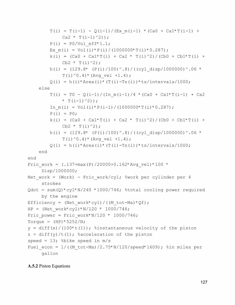
T(i) = T(i1) Q(i1)/(Ex_m(i1) *(Ca0 + Ca1*T(i1) + Ca2 * T(i1)2));
P(i) = P0/Vol_eff*1.1; Ex_m(i) = Vol(i)*P(i)/(1000000*T(i)*0.287); k(i) = (Ca0 + Ca1*T(i) + Ca2 * T(i)2)/(Cb0 + Cb1*T(i) +
Cb2 * T(i)2); h(i) = (129.8* (P(i)/100).8)/((cyl_disp/1000000).06 *
T(i)0.4)*(Avg_vel +1.4); Q(i) = h(i)*Area(i)*(T(i)Ts(i))*ts/intervals/1000; else T(i) = T0 Q(i1)/(In_m(i1)/4 *(Ca0 + Ca1*T(i1) + Ca2
* T(i1)2)); In_m(i) = Vol(i)*P(i1)/(1000000*T(i)*0.287); P(i) = P0; k(i) = (Ca0 + Ca1*T(i) + Ca2 * T(i)2)/(Cb0 + Cb1*T(i) +
Cb2 * T(i)2); h(i) = (129.8* (P(i)/100).8)/((cyl_disp/1000000).06 *
T(i)0.4)*(Avg_vel +1.4); Q(i) = h(i)*Area(i)*(T(i)Ts(i))*ts/intervals/1000; end end Fric_work = (.137+max(P)/20000+0.162*Avg_vel)*100 *
Disp/1000000; Net_work = (Work) Fric_work/cyl; %work per cylinder per 4
strokes Qdot = sum(Q)*cyl*N/240 *1000/746; %total cooling power required
by the engine Efficiency = (Net_work*cyl)/((M_totMa)*Qf); HP = (Net_work*cyl)*N/120 * 1000/746; Fric_power = Fric_work*N/120 * 1000/746; Torque = (HP)*5252/N; y = diff(x)/(100*t(1)); %instantaneous velocity of the piston z = diff(y)/t(1); %acceleration of the piston speed = 13; %bike speed in m/s Fuel_econ = 1/((M_totMa)/2.75*N/120/speed*1609); %in miles per
gallon A.5.2 Piston Equations
127

cos(θ) x = 2S +√l sin (θ)2 − ( )2
S 2 2 − l + 2S
el v = ∂t∂x
cc a = ∂t∂vel
Piston acceleration vs. Connecting rod length at 6200 RPM
maximum acceleration occurs at BDC
Con rod length L = S L = 1.5S L = 2S L = 2.5S L = 3S
max piston accel m/s2
21,800 19,500 18,200 17,500 17,000
Average piston velocity must be ≦ 15 m/s as per heywood 6200 RPM gives 14.3 m/s piston velocity vs. connecting rod length at 6200 RPM
128

Con rod length L = S L = 1.5S L = 2S L = 2.5S L = 3S
max piston velocity m/s
25.2 23.7 23.2 22.9 22.8
Crankpin acceleration at 6200 RPM X’’ = ω2r = (N*2*pi/60)2*(S/2) = 9500 m/s2 Maximum force from combustion F = combustion Pressure * B2/4 * pi = 7646 KPa * 8.30572 * pi / 4 = 41.4 kN = 9300 lbs Balance shafts reduce vibrations, but they do not remove stresses from the crankshafts Balancing engine: Every time components become unbalanced, there is vibration.
129

Primary balancing is balancing the components that could become unbalanced once in every rotation of the crankshaft. An inline four engine does not have any net primary forces or moments. Secondary balancing is balancing the components that have second order vibrations, i.e. forces that oscillate at twice the speed of the crankshaft.. The pistons accelerate more slowly at the top of the cycle than at the bottom; this is one major cause of vibration. A.5.3 Heat Transfer and Cooling In order to fine the amount of heat needed to be removed from the cylinders to keep the engine cool, we must find h between the hot gasses inside the cylinder and the cylinder wall. In the Stone book, there are many correlations. A simple correlation, which has sufficient accuracy in practice is the Hohenberg formula:
(v .4)h =V Ts0.06 0.4
129.8p0.8p + 1
From this
A(T )Q = h gas − Twall 130

Assuming a constant inner wall temperature of 150 C, though a 10 % reduction in cooling power will increase wall temperature by 10 C, in the team’s final MATLAB model, Q at 5000 RPM is 0.227 kJ per cylinder per 4 strokes. Simple conversion to imperial units, Heat loss rate from the gas to the walls is Q = 25.6 HP at 5000 RPM Temperature delta across the cylinder walls to the base of the fins is approximately 95C, assuming an average of 2 inches thickness from cylinder wall, x, to the base of the fins, an area, A, of about 100 in2 between the cylinder walls and the base of the fins, and using the heat conduction formula with a thermal resistor network model.
k (T )Q = xA
wall − T∞ The temperature of the base of the fins will be 50 C Based on the size of the engine, the critical dimensions and material properties of the fins are: length of fins ≈ 17 inches width of fins ≈ 3 inches thickness = .1 inches, we kaluminum = 151 W/mK Perimeter ≈ 23 inches Temperature at the outer surface of the fins is approximately 40C. At Tair = 30C, kair = .027 W/mK, viscosity is 0.019 mPas air speed is 30 m/s The Reynolds number is about 8x10⁵, using the formula for combined laminar and turbulent flow, the Nusselt number is found to be 975 with the next equation.
u (.037Re 71)Pr N = 4/5 − 8 1/3 Relating the nusselt number to the heat transfer coefficient h, it is found that
h = LNu k
The heat transfer coefficient h is calculated to be 57.9 Wm2K1. Plugging all the values into the next formula, Cooling power per fin can be calculated.
131

Q is found to be 461 watts per fin. Dividing necessary cooling power by the power per fin gives us that 42 fins in total are needed, or 21 per side. Natural convection case: At an idle of 800 RPM and an air to fuel ratio of 15:1, the engine needs approximately 8 percent throttle to maintain engine speed. At this operating condition, the engine must be cooled with about 600 watts of cooling power. If not the engine would eventually fail. In the case that the engine is idling, and the motorcycle is stopped, the cooling fins are operating in the natural convection regime, which means cooling capacity is severely reduced. In order to understand if the engine would fail under these conditions, and how quickly it would fail if it did happen, natural convection calculations must be done. Ideal fin spacing for natural convection is defined by a formula based on fin length and Rayleigh number:
.714Sopt = 2L
Ra1/4 The heat transfer coefficient is then defined by:
.31h = 1 kSopt
First, we must calculate the Rayleigh number. This is done using the following formula, where g is gravity, β is the coefficient of volume expansion, TS is the fin temperature, T∞ is the ambient temperature, L is the characteristic length, ν is the kinematic viscosity, and Pr is the Prandtl number.
a PrR = ν2gβ(T −T )Ls ∞
3
132

Using an ambient temperature of 30 C, an average fin temperature of 50 C, and a film temperature of 40 C, the Rayleigh number is calculated to be 1.746 x 10⁸. From this number, we can calculate the optimal spacing for the fins Sopt, and the heat transfer coefficient h. Sopt is found to be 1 centimeter, and from there, h is 3.5. However, these numbers are for vertical fins on a vertical heat sink, which is the ideal case for natural convection. On our engine, cooling is optimized for forced convection, with air moving along the engine from front to back. From this paper, it is seen that a vertical fin arrangement is 4.4 times as effective as a horizontal fin arrangement. Thus, the heat transfer coefficient is then 0.8 for the Rumblebug 1500 under natural convection conditions. With a temperature difference of 20 C, using this formula:
A(T )Q = h s − T∞
The heat dissipated per fin turns out to be about 2 watts per fin! Assuming this, the engine would need about 300 fins to not fail under natural convection conditions. Clearly this is not feasible. Using the calculated 42 fins, the engine would only have 85 watts of cooling power available, not nearly enough to keep the operating temperature low enough, and as such, the engine will fail at some point due to overheating. In the natural convection regime, fins aren’t the only source of significant cooling, but this will not increase cooling power significantly. Estimating that the engine can be cooled off at a rate of 120 watts, and that the necessary cooling power is 600 watts, the engine will heat up at a rate of 480 watts. Knowing this rate of heat accumulation, the specific heat of aluminum, the density of aluminum, the volume of aluminum needed to be cooled, and maximum allowed temperature of aluminum, this can be easily calculated. The density of aluminum is 2700 kgm3, the specific heat is 0.9 kJkg1K1, the maximum temperature is 250 C, the initial wall temperature is 150 C, and the volume of the aluminum dissipating the heat is 0.0046 m3. From these values, we found that the time to failure is 38 minutes. If the required engine cooling power is doubled, then the engine would fail in 16 minutes. A.6 List of Equations
133

Equation Number Equation
1 V cyl = NCyl
V RC
R + 1C
2 MA = RT 0
P V0 Cyl
3 V onstant P γ = C
4 TCombustion =
QA/FMA
FM (1+ )CA
1A/F V
+ TCompression
5 TCombustion =QF
(A/F + 1)CV+ TCompression
6 PPCombustion =TCombustionTCompression Compression
7 TExpansion = TCombustion( 1
RC)γ−1
8 PExpansion = PCombustion( 1RC)
γ
9 ηth = 1 −1
RCγ−1
10 (cos θ ) x = 2
S + 1 +√l sin θ2 − (2S)2 2 − l
11 T i = T i−1( xi
xi−1)γ − 1i−1
12
P i = P i−1( T iT i−1)
γ i−1γ − 1i−1
13 mep .97 .15( ) .05( )f = 0 + 0 N1000 + 0 N
10002
134

14 (V )W = ∑
2
P +Pi i−1i − V i−1
15 (v .4)h =V Ts0.06 0.4
129.8p0.8p + 1
16 A (T )Qi = hi i gas,i − Twall * tstep
17 mep(bar) .137 62vf = 0 + 200pmax + 1 p
18 (θ) xp[− ( ) ]x = 1 − e a Δθbθ − θ0 m+1
19 S = ( cR)2PμN
20 .5 .25 ≤ QRcnL ≤ 6
21 (v .4)h =V Ts0.06 0.4
129.8p0.8p + 1
22 A(T )Q = h gas − Twall
23 k (T )Q = xA
wall − T∞
24 u (.037Re 71)Pr N = 4/5 − 8 1/3
25 h = LNu k
26
27 .714Sopt = 2L
Ra1/4
135

28 .31h = 1 kSopt
29 a PrR = ν2gβ(T −T )Ls ∞
3
30 A(T )Q = h s − T∞ A.7 List of Abbreviations
Abbreviation Description
A/F Air to Fuel Ratio
CAD Computeraided Design
cc Cubic centimeter
CFR Code of Federal Regulations
CMM Coordinate Measuring Machine
CO Carbon Monoxide
EPA Environmental Protection Agency
FMEA Failure Modes and Effect Analysis
HC Residual Hydrocarbons
HP Horsepower
MPG Miles per gallon
MPI Magnetic Particle Inspection
NOx Nitrogen Oxides
tfmep Total frictional mean effective pressure
RPM Revolutions per minute
RPN Risk Priority Number
136

SFMM Surface Finish Measuring Machine
137