Rotordynamic Instability Problems in High-performance Turbomachinery
J. Wileman
I. Green
The George W. Woodruff School of Mechanical Engineering,
Georgia Institute of Technology, Atlanta, GA 30332
The Rotordynamic Coefficients of Mechanical Seals Hawing Two Flexibly Mounted Rotors The Reynolds equation is derived for a mechanical seal in which both elements are flexibly mounted to rotating shafts. Stiffness and damping coefficients for the fluid film are calculated for the three degrees of freedom of each element based upon a small perturbation analysis. The analogous coefficients for simpler configurations {e.g., flexibly mounted rotor, flexibly mounted stator) contained in the literature are shown to be obtainable as degenerate cases of the more general results presented in this work.
Introduction
Most current mechanical seal designs consist of a single rotating element (the rotor) which is separated by a thin film of the sealed fluid from a nonrotating element (the stator). These seals can have one of three basic configurations. In the flexibly mounted stator configuration (FMS) the stator is attached to the seal housing by means of a flexible support and anti-rotation locks, and the rotor is rigidly mounted to its shaft. Conversely, in the flexibly mounted rotor (FMR) configuration the stator is rigidly mounted to the seal housing while the rotor is attached to the shaft by means of a flexible support and positive drive devices. In either configuration misalignments resulting from imperfections in manufacturing and assembly are inevitable, and the purpose of the flexible support is to minimize the relative misalignment between the elements by allowing the flexibly mounted element to track the element which is rigidly attached, thus minimizing the leakage and reducing the probability of face contact.
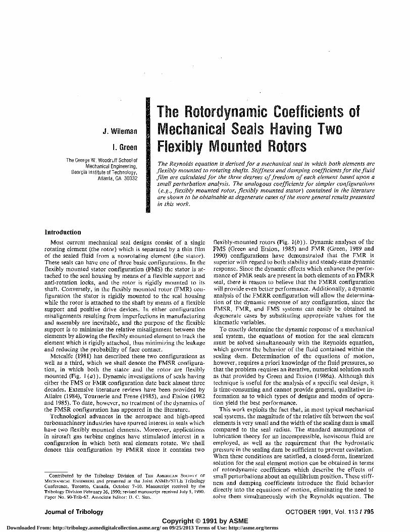
Metcalfe (1981) has described these two configurations as well as a third, which we shall denote the FMSR configuration, in which both the stator and the rotor are flexibly mounted (Fig. 1 (a)). Dynamic investigations of seals having either the FMS or FMR configuration date back almost three decades. Extensive literature reviews have been provided by Allaire (1984), Tournerie and Frene (1985), and Etsion (1982 and 1985). To date, however, no treatment of the dynamics of the FMSR configuration has appeared in the literature.
Technological advances in the aerospace and high-speed turbomachinery industries have spurred interest in seals which have two flexibly mounted elements. Moreover, applications in aircraft gas turbine engines have stimulated interest in a configuration in which both seal elements rotate. We shall denote this configuration by FMRR since it contains two
Contributed by the Tribology Division of THE AMERICAN SOCIETY OF MECHANICAL ENGINEERS and presented at the Joint ASME/STLE Tribology Conference, Toronto, Canada, October 7-10. Manuscript received by the Tribology Division February 26, 1990; revised manuscript received July 5, 1990. Paper No. 90-Trib-67. Associate Editor: D. C. Sun.
flexibly-mounted rotors (Fig. 1(b)). Dynamic analyses of the FMS (Green and Etsion, 1985) and FMR (Green, 1989 and 1990) configurations have demonstrated that the FMR is superior with regard to both stability and steady-state dynamic response. Since the dynamic effects which enhance the performance of FMR seals are present in both elements of an FMRR seal, there is reason to believe that the FMRR configuration will provide even better performance. Additionally, a dynamic analysis of the FMRR configuration will allow the determination of the dynamic response of any configuration, since the FMSR, FMR, and FMS systems can easily be obtained as degenerate cases by substituting appropriate values for the kinematic variables.
To exactly determine the dynamic response of a mechanical seal system, the equations of motion for the seal elements must be solved simultaneously with the Reynolds equation, which governs the behavior of the fluid contained within the sealing dam. Determination of the equations of motion, however, requires a priori knowledge of the fluid pressures, so that the problem requires an iterative, numerical solution such as that provided by Green and Etsion (1986a). Although this technique is useful for the analysis of a specific seal design, it is time-consuming and cannot provide general, qualitative information as to which types of designs and modes of operation yield the best performance.
This work exploits the fact that, in most typical mechanical seal systems, the magnitude of the relative tilt between the seal elements is very small and the width of the sealing dam is small compared to the seal radius. The standard assumptions of lubrication theory for an incompressible, isoviscous fluid are employed, as well as the requirement that the hydrostatic pressure in the sealing dam be sufficient to prevent cavitation. When these conditions are satisfied, a closed-form, linearized solution for the seal element motion can be obtained in terms of rotordynamic coefficients which describe the effects of small perturbations about an equilibrium position. These stiffness and damping coefficients introduce the fluid behavior directly into the equations of motion, eliminating the need to solve them simultaneously with the Reynolds equation. The
Journal of Tribology OCTOBER 1991, Vol. 113 / 795
Copyright © 1991 by ASMEDownloaded From: http://tribology.asmedigitalcollection.asme.org/ on 09/25/2013 Terms of Use: http://asme.org/terms
Anti-RotaHon Lock
Spring
Seal Housing
Sea) Ring
Flexibly Mounted Rotor
Elastomer Secondary Seal
Low Pressure
Fig. 1(a)
Flexibly Mounted Rotor
I p-—Elastic Secondary Seal
I
Leakage
Rotor Nutation y2-
- Positive Drive Device
Fig. 1(b)
Fig. 1 Schematics of (a) FMSR and (b) FMRR mechanical face seals
equations of motion can then be analyzed for stability or steady-state response. Green and Etsion (1983) provided stiffness and damping coefficients for the fluid film in the FMS configuration, and Green (1987) provided similar coefficients for the FMR configuration.
To determine rotordynamic coefficients for the FMRR configuration, the appropriate form of the Reynolds equation is derived based upon the kinematic description of the system. The Reynolds equation is then solved to obtain the hydrostatic and hydrodynamic pressure distribution within the sealing dam, and these pressures are integrated over the surface area of the seal faces to determine the forces and moments applied by the fluid film. Finally, the rotordynamic coefficients are obtained as derivatives of these forces and moments about the equilibrium configuration of the system.
Kinematic Description
In an FMRR seal, the forces and moments applied to the seal elements by the fluid film and the flexible support depend upon many different types of relative motion, while the iner-
tial forces and moments depend upon the absolute motion of each element. In order to describe each of these relationships in its most useful manner, this analysis utilizes six different coordinate systems. Each of the coordinate systems described below is right-handed. Superscripted asterisks are used with some variables to distinguish them from their normalized counterparts defined later.
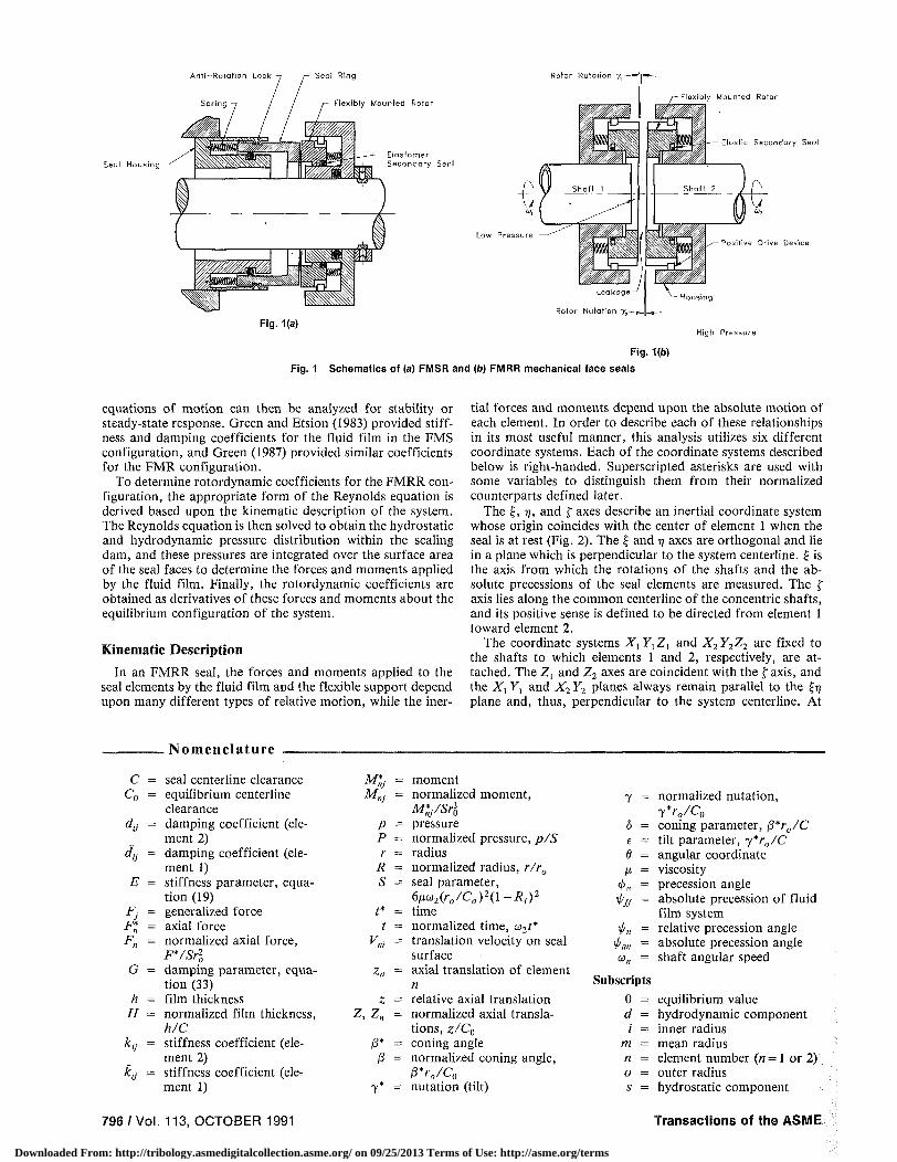
The £, 7], and f axes describe an inertial coordinate system whose origin coincides with the center of element 1 when the seal is at rest (Fig. 2). The £ and r\ axes are orthogonal and lie in a plane which is perpendicular to the system centerline. £ is the axis from which the rotations of the shafts and the absolute precessions of the seal elements are measured. The f axis lies along the common centerline of the concentric shafts, and its positive sense is defined to be directed from element 1 toward element 2.
The coordinate systems XlYlZl and X2Y2Z2 are fixed to the shafts to which elements 1 and 2, respectively, are attached. The Zl and Z2 axes are coincident with the f axis, and the Xx Yx and X2 Y2 planes always remain parallel to the £TJ plane and, thus, perpendicular to the system centerline. At
N o m e n c l a t u r e
C = seal centerline clearance C0 = equilibrium centerline
clearance djj = damping coefficient (ele
ment 2) dy = damping coefficient (ele
ment 1) E = stiffness parameter, equa
tion (19) Fj - generalized force F* = axial force F„ = normalized axial force,
F*/Sr20
G = damping parameter, equation (33)
h = film thickness H = normalized film thickness,
h/C ktJ = stiffness coefficient (ele
ment 2) kjj = stiffness coefficient (ele
ment 1)
M*j = moment MnJ = normalized moment,
M*/Srl p = pressure P — normalized pressure, p/S r = radius
R = normalized radius, r/r0
S = seal parameter, 6pu2(r0/C0)m-R,)2
t* = time t = normalized time, w2t*
V„t = translation velocity on seal surface
z„ = axial translation of element n
z = relative axial translation Z, Z„ = normalized axial transla
tions, z/C0
/3* = coning angle /3 = normalized coning angle,
P*ro/C0
y* = nutation (tilt)
7 = normalized nutation, y*ro/c0
5 = coning parameter , fi*r0/C e = tilt parameter , y*r0/C d = angular coordinate ix = viscosity
4>n = precession angle \pff = absolute precession of fluid
film system \j/„ = relative precession angle
\j/m = absolute precession angle o>„ = shaft angular speed
Subscripts 0 = equilibrium value d = hydrodynamic component ; = inner radius
m = mean radius n = element number (n = 1 or 2) o = outer radius s = hydrostatic component
796 / Vol. 113, OCTOBER 1991 Transactions of the ASME
Downloaded From: http://tribology.asmedigitalcollection.asme.org/ on 09/25/2013 Terms of Use: http://asme.org/terms
every instant the origin of the Xn YnZn system coincides with the center of element n, so that either of the shaft-fixed systems can be related to the inertial system by a single planar rotation transformation and a translation along the f axis. When the seal is at rest, the Xx YlZl system coincides with the inertial system, and the X2 Y2Z2 system differs only in that its origin is translated in the f direction through a distance equal to C0, the initial centerline clearance between the seal elements. When the shafts begin to rotate, the X„ axis leads the £ axis by an angle u„t, where o>„ is the constant angular velocity of element n.
The xxyxzx and x2y2z2 systems are principal systems of their respective seal elements and may have both a precession and a nutation with respect to their corresponding shaft-fixed systems as well as with respect to the inertial system. The x„ and y„ axes form a plane which coincides with the sealing face of element n, and 7* represents the nutation of the z„ axis with respect to the f axis. In a practical seal design, touchdown usually occurs if the magnitude of 7* exceeds a few millira-dians, so that it is quite accurate to make the approximations
cos7* = l; sin 7* =7* (1)
where 7* can represent the nutation of either element. The x„ axis always remains parallel to the Xn Yn plane (i.e.,
it always remains perpendicular to the shaft centerline) and the yn axis is always directed toward the point of maximum separation between the face of element n and the X„ Y„ plane; these constraints are sufficient to uniquely describe the orientation of the system. The angle by which axis x„ leads axis X„ is denoted by t/<„, and the angle by which xn leads £ is denoted by \pan, since the latter represents the absolute precession of the x„ynz„ system. The two precession angles are thus related by the expression
and the two precession rates are related by
The analysis of the fluid film behavior in the sealing dam utilizes the assumptions of lubrication theory, so that inertia effects within the fluid film are neglected and the fluid behavior depends upon the relative positions and motions of the two sealing faces rather than upon their absolute positions and motions. Therefore, it is most convenient to determine the fluid film pressures (i.e., solve the Reynolds equation) using a coordinate system which describes the position of one sealing face with respect to the other. We designate this system using the 1, 2, and 3 axes.
To maintain consistency throughout the derivation, we define 123 to be a principal system of element 1. Thus, axes 1 and 2 form a plane which coincides with the xxyx plane (the sealing face of element 1) and axis 3 is orthogonal to the plane and directed toward element 2. Axes 1 and 2 precess about zx
so that axis 1 is always parallel to the x2y2 plane (the sealing face of element 2) and axis 2 is always directed toward the point of maximum film thickness, which represents the maximum separation between the sealing faces. Axis 3 coincides with axis Z\ and is nutated with respect to axis z2 through an angle 7*, which represents the relative tilt between the two elements. As mentioned previously, the nutations in any practical mechanical seal are extremely small; thus, the nutation angles can be treated as vectors which satisfy the relation
7* = 7 ! -T *
The angle <j>x is defined to be the angle, measured in the xxyx
plane, by which axis 1 leads axis xx, and the absolute precession of the fluid film system, 1/^, satisfies
^ / /= 1 1 +01 C°S 7* Substituting (1) into this expression yields.
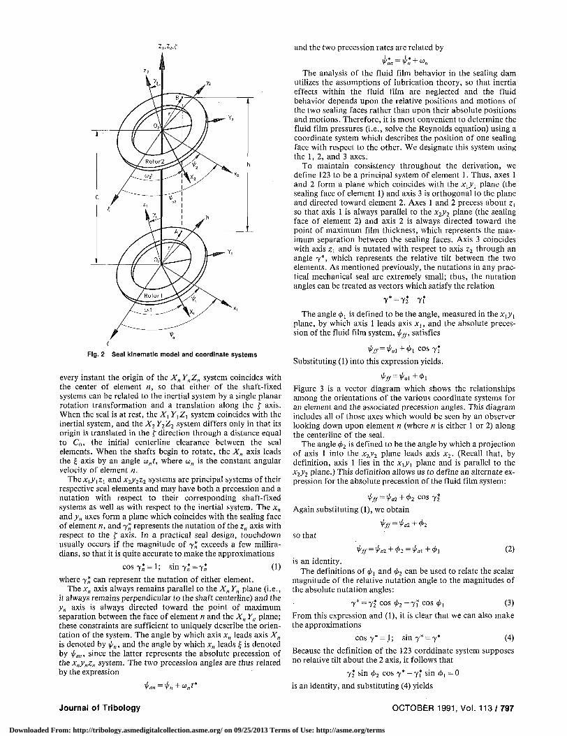
Figure 3 is a vector diagram which shows the relationships among the orientations of the various coordinate systems for an element and the associated precession angles. This diagram includes all of those axes which would be seen by an observer looking down upon element n (where n is either 1 or 2) along the centerline of the seal.
The angle <f>2 is defined to be the angle by which a projection of axis 1 into the x2y2 plane leads axis x2. (Recall that, by definition, axis 1 lies in the xxyx plane and is parallel to the x2y2 plane.) This definition allows us to define an alternate expression for the absolute precession of the fluid film system:
*l/ff = i/a2 + (l>2 COS 7 |
Again substituting (1), we obtain
^ff=Tpal+<t>2
so that
^ff=^a2+^2 = a\+^l (2) is an identity.
The definitions of 4>x and 4>2 can be used to relate the scalar magnitude of the relative nutation angle to the magnitudes of the absolute nutation angles:
7* =72 cos </>2-Yi cos </>, (3)
From this expression and (1), it is clear that we can also make the approximations
cos7* = l; sin 7* =7* (4)
Because the definition of the 123 corddinate system supposes no relative tilt about the 2 axis, it follows that
72 sin 4>2 cos 7* - 7* sin </i, = 0
is an identity, and substituting (4) yields
Journal of Tribology OCTOBER 1991, Vol. 113 / 797
Downloaded From: http://tribology.asmedigitalcollection.asme.org/ on 09/25/2013 Terms of Use: http://asme.org/terms

Fig. 3 Vector diagram showing relationship of coordinate axes for a single element as viewed down the system centerline
72*sin</>2-7f sin </>,=0 (5)
As stated previously, the purpose of the 123 system is to allow a description of the position of element 2 with respect to element 1. However, when deriving and solving the Reynolds equation it will be convenient to work with a cylindrical, rather than rectangular, system. To this end we define a cylindrical system in which the position of a point in the sealing dam is denoted by its distance r from the origin of the 123 system and the angle 0 between axis 2 and a line through the origin and the point (represented by either A or B in Figs. 2 and 3). The axial direction of the cylindrical system is the 3 axis. Because 123 is a principal system of element 1, the value of coordinate 3 on the sealing face of element 1 is always zero. On element 2 the value of coordinate 3 is the local value of h, which is the separation between the elements (i.e., the film thickness). For a coned-face seal the film thickness is defined by (see, for example, Green, 1987)
A = C + 7 * r c o s 0 + 0*(r - r ( ) (6)
where C is the clearance between the elements at the shaft centerline, (3* is the coning angle, and r, is the inner radius of the sealing dam. It is important to note that h varies with time (since 7* and C are time-varying) and with both radial and circumferential position on the sealing dam.
The Reynolds Equation
Because of the kinematic complexity of the FMRR configuration, it will be more rigorous to derive the applicable form of the Reynolds equation than to rely upon the standard forms commonly used in the analyses of simpler systems. For example, when only one seal element rotates, the sqeeze effect is represented by a term containing dh/dt, but for the FMRR case the evaluation of dh/dt depends upon assumptions regarding the velocities of the seal faces at the point where it is evaluated. To avoid making assumptions which are difficult to justify, the derivation of the Reynolds equation for the FMRR configuration is based upon a more fundamental form of the equation.
Haardt and Godet (1975) present the Reynolds equation in cylindrical coordinates in terms of the translation velocities on
798 /Vol . 113, OCTOBER 1991
the boundary surfaces, which are the seal faces in our case, and we shall base out derivation upon this equation. Etsion (1980) has shown that the effects of the circumferential pressure gradient and of the sealing dam curvature become insignificant as the ratio of the inner radius of the sealing dam to the outer radius (r,/r0) approaches unity (the "narrow seal" approximation). Applying these simplifications to the equation of Haardt and Godet, the form of the equation applicable to the cylindrical coordinate system is (Wileman, 1990)
d /h3 dp \ dh r^iT^) = l2r{v*-v^-6(V2°-Vw)-W
-6r(V2r-Vlr)^- +6h-^-(V2e+Vle) (7)
+ 6rh— (V2r+Vlr)+6h(V2r+Vlr) or
The velocities, Ky, in the right-hand side of the equation represent the translational velocities with respect to inertial of a point on the surface of a seal element. The numeral in the subscript denotes which element is being considered, and the letters r, 0, and z denote, respectively, the radial, circumferential, and axial velocity components.
The velocity of a point on the face of a seal element is a superposition of the velocity of axial translation of the center of the element and the velocity of the point with respect to the center which results from the element rotation. The latter component of velocity is obtained at any point as a cross-product of the angular velocity of the element with the r03 position of the point. Thus, to perform this computation we would like to obtain the absolute angular velocity of each element expressed in the cylindrical coordinate system. Green and Etsion (1986b) obtained the absolute angular velocity for the FMR case expressed in the element principal coordinate system. With an appropriate substitution of variable names, that expression may be applied to both elements in the FMRR configuration; thus,
X, = -yfr + to sin 7fy! + [to (cos 7f - 1) + w, ]k1 (8a)
*2 = Y2'2 + to sin 72/2 + ito(c°s 72* - 1) + "2^2 (8*)
We wish to resolve both of these angular velocities into the r03 system. We note that for element 1, 3 and kl are coincident; thus, only the lx and y, components need be resolved. From Figure 3 we see that the unit vectors in the two systems are related by
?! = -er sin^ + ^ j ) - ^ cos(0 + </>i)
y, =er cos(0 + 0 , ) - e0 sin(0 + <£,)
Substituting these relations into (8a) and utilizing the approximations (1), we obtain the absolute angular velocity of element 1 expressed in cylindrical coordinates:
\i=[-yj sirHO + tJ + toyl co&iO + We,
+ [-yt cosid + O-toyt sin(e + <t>l)]ee + oll3
Expressing the angular velocity of element 2 in the fluid film coordinate system requires a more complex procedure because the r63 system is not a principal system of element 2; the z2
axis is nutated with respect to the 3 axis, and the x2y2 plane is inclined to the rd plane. The value of the 3 coordinate at any point on element 2 will be the film thickness at that point.
To resolve the angular velocity into r, 0, and 3 components, we shall derive a rotation transformation from the element relative system, x2y2z2, to the fluid system, rd3. It will be most convenient to define this rotation transformation in terms of three successive body-fixed rotations, then to obtain the complete transformation using matrix multiplication.
The first rotation, Rlt transforms the components referenced to the x2y2z2
s y s t e m m t o components of an intermediate
Transactions of the ASME
Downloaded From: http://tribology.asmedigitalcollection.asme.org/ on 09/25/2013 Terms of Use: http://asme.org/terms
system, xmymzR\. The second rotat ion, R2, t ransforms the components with respect to this intermediate system into components with respect to a second intermediate system, xR2yR2ZR2- The final rotat ion, R}, t ransforms the xR2yR2ZR2 components into components with respect to the r03 system. The complete rotat ion transformation, R, is then obtained using
(9) R-R3R2R1
so that
= R (10)
To obtain i?[ we rotate through an angle 4>2 about axis z2 so that
12;f" COS (/)2
- sin (/>2
0
sin <#>2
COS 4>2
0
<n 0 i ^
r*0 \yi
UJ = R,
fx2 \y2
U2
(11)
Since (j>2 is defined as the angle by which a projection of axis 1 into the x2y2 plane leads axis x2 (Figure 3), the transformation R, is equivalent to rotat ing the *2.y2Z2 system about axis z2 until axis x2 coincides with the projection of axis 1.
After performing this rotat ion, we nutate the system through the angle 7*, defined in (3), about axis xRi, which represents the new position of the x2 axis. This body-fixed rotation is denoted R2 and is defined by
yu2 ZR,
1 0 0 cos 7* 0 sin 7*
0 -sin 7* cos 7*
fxRl ] y R l
l z R .
= R, yR}
(12)
After Rt and R2 have been performed, the new position of the z2 axis, denoted by zR., will coincide with the 3 axis, and we perform a third body-fixed rotation about this axis to bring ZR. into coincidence with the r axis. The angle through which the system must be rotated is 8 + i r /2 , and after substituting appropriate tr igonometric identities, the transformation R3 is defined by
(13)
Before multiplying to obtain the complete t ransformation, we utilize the approximations of (4) to simplify the trigonometric functions contained in R2. Then, substituting (11), (12), and (13) into (9), we obtain
sin 8 cos 6 0
cos 6 ( P - sin 0 0
0 \ j
f-%1 1 y*2 f
U 2 J = R3
[xRj y*i
1**2
R-- s i n ( 0 + </>2) cos(0 + </>2) —7* cos 0" - c o s ( 0 + </>2) - s i n ( 0 + </>2) 7* sin 8 — 7* sin 4>2 y* cos 4>2 1
We substitute this into (10), and use it to transform the angular velocity of element 2 expressed in (8b) into the cylindrical coordinate system. The result is
A2 = [ - 7 f sm(,8 + <t>2) + i*2y2 cos(0 + 0 2 ) - 7 * " 2 cos 8]er
+ [ - 72* cos(0 + 0 2) - i*2j2 sin(0 + 0 2 ) + 7*co2 sin 0]e„ + co23
To obtain the velocity components to be substituted into (7), we recall that the definition of the fluid film system requires that the 3 coordinate of every point on element 1 be zero. Thus , the position vector of any point on element 1 in the r03 system is simply r, =rer, and the velocity of the point which results from the element rotat ion is obtained from the cross-product V! = Xj x r , . Evaluating the cross-product and adding the axial translation velocity, i\, yields
v,=/-co1e s + [/-7*cos(6l + 0 1 ) + ^ * 1 7 * s i n ( 0 + 0 1 ) + Zi]3
and the velocity components which we substitute into equation (7) are
Vw = 0 (14a)
K 1 9 = T O l (146)
K u = r y f cos(6> +</>!) + ^ 7 ? s i n ^ + ^ + Zi (14c)
On element 2 the value of the 3 coordinate at each location is equal to the film thickness at that location, and the position vector becomes ' r 2 =re/+ h3, where h is defined in (6). The velocity is computed as the sum of the cross product , v2 = X2 x r2, and the axial velocity, z 2 , so that
v2 = roi2eg + [ry2 cos(0 + <t>2) + r\p*2y2 sin(0 + <£2)
-ry*o>2sm 0 + z2]3
where products of h and 7* have been neglected because they are second order . The velocity components which we substitute into equation (7) are
V2r = 0 (15a)
K » = R O 2 (15b)
Viz^nl cos(8 + (t>2) + ri*2y^ sin(0 + </>2)-ry*o>2 sin 8 + z2
(15c)
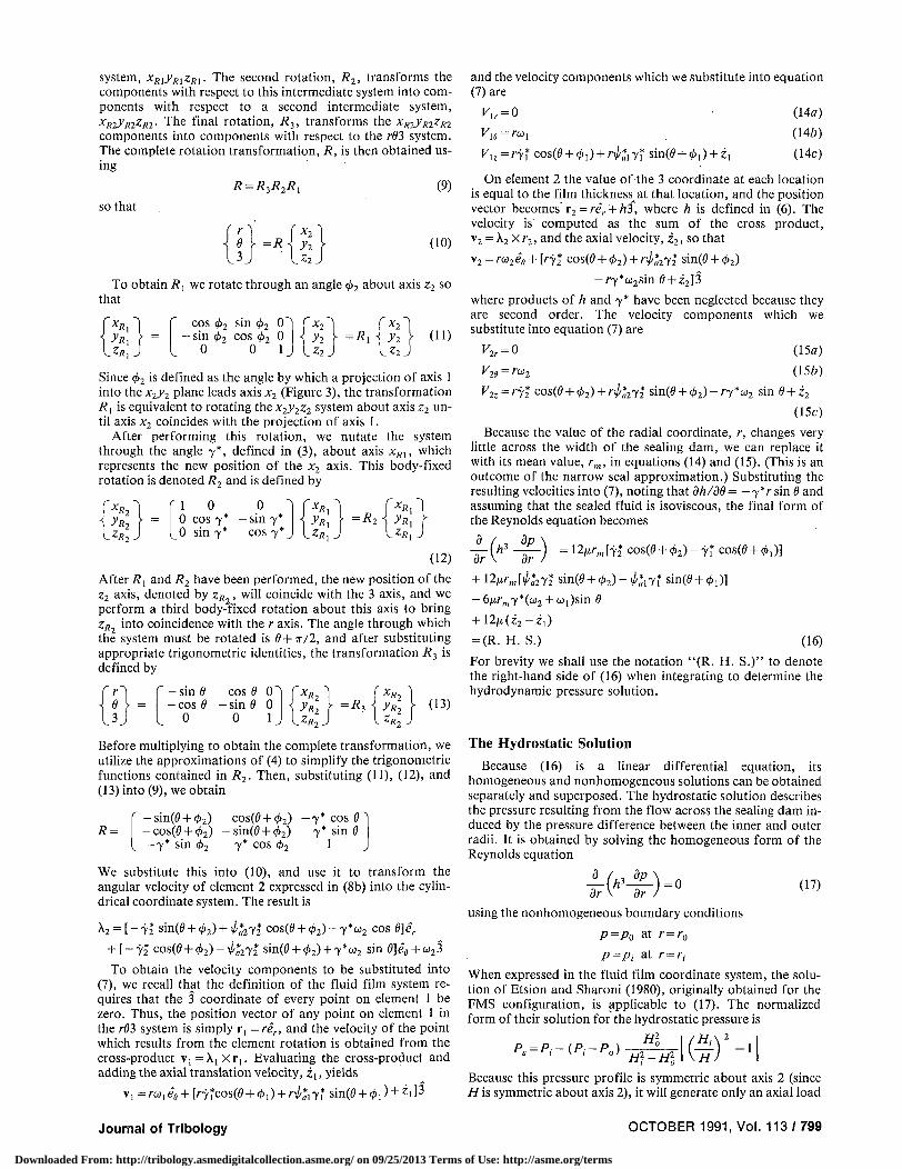
Because the value of the radial coordinate, r, changes very little across the width of the sealing dam, we can replace it with its mean value, /•,„, in equations (14) and (15). (This is an outcome of the narrow seal approximation.) Substituting the resulting velocities into (7), noting that dh/dd = — 7 V sin 0 and assuming that the sealed fluid is isoviscous, the final form of the Reynolds equation becomes
dr -(*•-£•) l2A""miY2* cos(0 + 0 2 ) - 7 f cos(0+ (£,)]
fe)-l/-:i7i sin(0 + «,)] + 12/xr„,[^272*sin(0 + <
-6/iA-m7*(co2+u1)sin 8
+ I2n(z2-zl) = (R. H . S.) (16)
For brevity we shall use the notat ion " (R . H . S . )" to denote the right-hand side of (16) when integrating to determine the hydrodynamic pressure solution.
The Hydrostat ic So lut ion
Because (16) is a linear differential equation, its homogeneous and nonhomogeneous solutions can be obtained separately and superposed. The hydrostatic solution describes the pressure resulting from the flow across the sealing dam induced by the pressure difference between the inner and outer radii. It is obtained by solving the homogeneous form of the Reynolds equation
d
17 ( " • # - )
= 0 (17)
using the nonhomogeneous boundary conditions
P=Po at /• = /•<,
P=Pi a t /• = /•,•
When expressed in the fluid film coordinate system, the solution of Etsion and Sharoni (1980), originally obtained for the FMS configuration, is applicable to (17). The normalized form of their solution for the hydrostatic pressure is
P s = P , - ( P , - P 0 ) ^ r [ ( § ) 2 - i ]
Because this pressure profile is symmetric about axis 2 (since / / i s symmetric about axis 2), it will generate only an axial load
Journal of Tribology OCTOBER 1991, Vol. 113 / 799
Downloaded From: http://tribology.asmedigitalcollection.asme.org/ on 09/25/2013 Terms of Use: http://asme.org/terms

and a tilting moment about axis 1 upon each of the seal elements.
The hydrostatic forces acting upon the seal elements are obtained by integrating the hydrostatic pressure over the surface area of the sealing dam; thus,
F2s = 2R,„ j * J^ P, dRdO; Fls = - F *
where the narrow seal approximation has again allowed us to replace R with Rm and remove it from the integral. Since, in general, the forces and moments which act upon element 1 are simply the negatives of those which act upon element 2 (when expressed in the fluid film coordinate system), we shall hereafter consider only those forces and moments which act upon element 2. Utilizing the evaluation of the integral by Et-sion and Sharoni (1980) for small nutations, we obtain
7T
~2~ ( i - # ? ) ( p , + p 0 ) + T T ( P 0 - p , ) 5 ( i - ; ? , ) £ (18)
where, following the normalization procedure of Green and Etsion(1983)
E = i}-R,)R„ (19) 2 + 5(1 -/?,-)
The first term of (18) represents the force which would result if the seal elements were perfectly aligned and unconed. The second term is the deviational component which results from coning. The relative tilt between the two elements, 7, does not appear in the hydrostatic expression because the result of the integration contains 7 only to second order and higher.
The definition of the hydrostatic moment about the 1 axis acting upon element 2 is
M2ls = 2Rl[ * [ Ps cos 6 dRdd J0 J R:
(20)
where the first digit of the subscript denotes the element to which the moment is applied and the second denotes the axis (in the fluid film system) about which the moment acts. The positive sign for (20) is obtained by noting that a positive pressure at 8 = 0 results in a positive moment applied to element 2 about axis 1. Again utilizing the evaluation of Etsion and Sharoni (1980), the moment is
M 2„ = x ( P 0 - P , ) £ 2 ( l - f i i J / ) £ (21)
In this expression the dependence upon the relative tilt angle, 7, is contained completely within the dimensionless tilt parameter, e, where e = y*r0/C.
The Hydrodynamic Solution
The hydrodynamic pressure is obtained by solving equation (16). However, since the effect of the pressure difference across the sealing dam is contained within the hydrostatic solution, we solve the nonhomogeneous equation using the homogeneous boundary conditions
(22) p = 0 at /• = /•„
p = 0 at /• = /•,-
Thus, the particular solution will represent that portion of the fluid pressure which results only from the relative motion of the two seal elements. It will include both hydrodynamic and squeeze effects, but we shall not attempt to demarcate the two because the complexity of motion in the FMRR configuration makes the definition of separate hydrodynamic and squeeze effects ambiguous.
Integrating (16) once and dividing by h3, we obtain
dp r—r' = (R. H. S.) dr h3
tion of the extremum of hydrodynamic pressure. Integrating a second time, we obtain
p = (R. H. S.) f r-r'
dr (23)
If the hydrodynamic solution is nontrivial, (R. H. S.) will be nonzero. Therefore, if the boundary conditions (22) are applied to (23), the value of the integral at /• = /•,• and r = r0 must be zero. These two conditions can be used to evaluate r' and the constant resulting from the second integration with the result
dr = {r0-r)(r~ri)
J h3 2h2hm
We substitute this into (23) to obtain the hydrodynamic pressure, then normalize the result by dividing the equation by the seal parameter, 5, and substituting the identity
C = C 0 ( 1 + Z )
= C 0 ( 1 + Z 2 - Z , )
into the normalization for H. The resulting normalized hydrodynamic pressure is
A ( l_R'){Rm[y2cos(d+4>2) (1+Z) 3
-7 , cos(6> + 0,)]+i?m[72i/-K2 sin(0 + <j!>2)-71i/<ol sin(0+ <£,)]
^ 0 + ^ ) 7 sin 6 + Z2-z] (24)
where
\-R
Hmmi-R,) The hydrodynamic pressure alone will normally be negative at some point on the seal circumference. However, this work assumes that the total pressure, which is the sum of the hydrodynamic and hydrostatic pressure solutions, will be greater than zero around the entire circumference, so that there is a full fluid film in the sealing dam. If a negative total pressure occurs, the fluid film will cavitate, and the pressure solutions used to obtain the hydrodynamic moments will be invalid.
The definitions of the hydrodynamic forces and moments acting upon element 2 are
F2d=Rm\2Q
T \lRPddRd6 (25)
Mr
Mr.
J 2?r (• 1
{ 2TT p 1
0 L
cos 6 dRdd
P, sin 6 dRdd
(26)
(27)
When (24) is substituted into each of these definitions, the R dependence in each integrand is contained within the term
(1-R)(R-R:)
Green and Etsion (1983) denote the integral of this expression with respect to R as T(d)\ i.e.,
" (l-R)(R-R,) T(d)=\ dR
The integral is evaluated in their appendix, and the result is
\nHn-\nH, l-R, 1
(28)
™=>m where r' is a constant of integration equal to the radial loca-
(<5 + e cos0)3 Hm{S + e cos 6)2 J
When (28) is substituted into (25) through (27), the integration over R in each expression becomes
800 / Vol. 113, OCTOBER 1991 Transactions of the ASME
Downloaded From: http://tribology.asmedigitalcollection.asme.org/ on 09/25/2013 Terms of Use: http://asme.org/terms

r JR:
PddR = T(6)
(1 + Z) 3 (1- /? , ) ~T{Rm[y2cos(d + <t>2)
-7, cos(6 + (t>i)]+Rm[72^2 sin(0 + 4>2)-7i'/'oi sin(0 + <Ml
^ ( l + ^ T s i n f l + Z . - Z , ] , v- . . . (29) 2 \ co2
In order to simplify the integration with respect to 6, we employ the approximation of Green and Etsion (1983) and define e = e/5, assuming that ( e / 5 ) 2 « l , so that T(6) can be rewritten as
2a'(1) 2 cos 6
ne)= —-~ + —-=— [«(i)r-«(/j,)-3a'(i)£i 53
2(1-/?,) 5 2 [ l+5( /? m - /? , ) ]
where
+ 2(1-/?,) cos 8 r a (/?,„) +2e
52
1 r a
17+ 5(/?„,-/?,-)
a(R) = eR
l + 5 ( / ? - / ? , )
and
a ' ( / ? ) = l n [ l + 5 ( / ? - / ? , ) ]
This'substitution eliminates all dependence upon 6 from the arguments of the logarithms and removes all trigonometric functions from the denominator of the integrand.
The integration over 8 is performed in the Appendix, and the hydrodynamic forces and moments which result are
F2d=-A*RmG(Z2-Zl) (30a)
(306) F\d = ~F2d
M2ld= -2irRlp{y2 cos </>2-7i cos 4>{
+ y2^a2 sin </>2-7iiai sin <t>i\ (31«)
Mud=-M2ld (316)
M22d = 2irRlp\[y2 sin </>2-7i sin 0,]
- [ 7 2 ^ 2 cos tf>2-7itai cos (/>,]+ - ^ - ( 1 + — ^ — J T J (32a)
(326) Mm=-M2:
where
ln [ l+5(1- /? , ) ] -26(1-/?,)
2 + 5(1-/?,)
53(1 + Z) 3 (1 - / ? , ) 2 (33)
Since we wish to express the stiffness and damping coefficients with respect to the fluid film coordinate system, we must first express the fluid film moments with respect to this system. The hydrostatic moment, (21), presents no problem as it is already expressed with respect to the fluid film system. However, the hydrodynamic moments, (31) and (32), are expressed in terms of the nutations 72 and yu which are referenced to the element principal systems x , / ^ ! and x2y2z2. Thus, (31) and (32) must be transformed so that the hydrodynamic moments are expressed with respect to the relative nutation angle, 7, and its time derivative, 7.
We begin this transformation by taking the derivative with respect to time of the kinematic relations (3) and (5) to obtain
7 = 72 cos <j>2 - 7 , cos 4>i -72^2 s i n </>2 + 7i0i sin <f>l (34a) 0 = 72 sin </>2-7i sin <£, +y24>2 cos </>2—Ti<Ai cos </>, (346)
Substituting (2), (5), and (34a) into (31a), M2Xd can be expressed as
M2ld=-2TrRlPy To express M22d in terms of the relative nutation, we first
take the time derivative of (2) to obtain
Substituting into (32a) yields
M22rf = 27r/?3p^[72 sin 4>2~yi sin 0 J
- [ 7 2 ( ^ - * 2 > c ° s </>2-7i('/'//-0i)cos <£[]
.•-rO • - * > ] Then substituting (346) and (3) we obtain
Stiffness and Damping Coefficients
A rotordynamic coefficient represents the change in the magnitude of a generalized force which results when a single degree of freedom is perturbed while all others are held at their equilibrium positions. Stiffness coefficients, k, correspond to perturbations of position while damping coefficients, d, correspond to perturbations of velocity.
A rotordynamic coefficient represents a relationship between the degree of freedom in which the perturbation occurs and the degree of freedom in which the generalized force acts. To uniquely describe which two degrees of freedom are related by a particular coefficient, this work will adopt a notation in which each rotordynamic coefficient contains two subscripts. The first subscript will denote the degree of freedom in which the perturbation occurs, and the second will denote the degree of freedom in which the generalized force acts. It is most convenient to express the rotordynamic coefficients with respect to the fluid film coordinate system; therefore, both degrees of freedom denoted in each subscript will be referenced to this system. Rotations and moments about axes 1 and 2 will be denoted by the numerals 1 and 2 while the numeral 3 will denote axial translations and forces.
The definitions of the stiffness and damping coefficients are of the form
ku=- du=-dX,
where Fj represents a generalized force acting in degree of freedom j , Xt represents a perturbation occurring in degree of freedom /, and Xt represents a perturbation of the velocity in degree of freedom /. The equilibrium configuration is defined to be that in which both seal elements are perpendicular to the seal centerline; in which the centerline clearance, C, takes on its initial value, C0; and in which the velocities in each degree of freedom are zero. Thus, in the equilibrium configuration all of the position variables (Z, 7, , y2, and 7) and their time derivatives are zero, and these zero values are substituted into the evaluations of the partial derivatives to determine the expressions for the stiffness and damping coefficients. The generalized forces can then be obtained from the coefficients using the relation
FJ=FJ\ - E M O - I X * / (35)
For most seal designs, the inner and outer radii of the sealing dam are selected in such a way that the equilibrium forces and moments which act upon the seal sum to zero, a process known as balancing, so that Fj \eq =0 .
Since each generalized force which results from fluid film effects acts upon both element 1 and element 2, we define our coefficients k,j and dy as derivatives of the generalized forces which act upon element 2. Then, since the generalized forces which act upon element 1 are the negatives of those which act upon element 2, the fluid film coefficients which will be used
Journal of Tribology OCTOBER 1991, Vol. 113 / 801
Downloaded From: http://tribology.asmedigitalcollection.asme.org/ on 09/25/2013 Terms of Use: http://asme.org/terms

to derive the equations of motion for element 1 will simply be the negatives of the ky and dy values determined for element 2.
The Axial Modes
From (18) and (30) it is clear that the degrees of freedom corresponding to axial translations are uncoupled from those which represent rotations of the seal elements. Each of the axial forces is affected only by perturbations in the axial positions and velocities of the two elements so that kn and k23 are identically zero, as are the analogous damping coefficients. The nonzero rotordynamic coefficients in the axial mode are defined as follows:
k\\ —
dn =
dF2
dZ
dF2
Hz
(36a)
(366)
To obtain kn from (36a), we perform the derivative, then require that all velocities and displacements be zero. Since Z = 0, the hydrodynamic component of the axial force will not contribute to kn. The first term of the hydrostatic load of equation (18) is a constant and vanishes when differentiated, so that the expression for the axial stiffness reduces to
k3i=-ir(P0-Pl)(l-Rl)—-(SE) (37) oz
We substitute equation (19) and the relation
l+Z
to evaluate the derivative in (37), then substitute Z = 0 into the result to obtain
k3i=*{P0-Pi) R,„
2/3
where E0 is the value of E when all displacements and velocities are zero:
En = (1 - * , ) * „
2 + 0 ( 1 - * , )
The damping coefficient in the axial mode is obtained from the hydrodynamic component of the axial force; thus,
di3 = - -L[-4irRmGZ]
Since G is independent of the velocity, the result is simply
dn=4irRmG0
where G0 is the value of G at equilibrium:
l n [ l + 0 ( 1 - « , ) ] •
G0 =
2 0 ( 1 - * , ) 2 + 0(1-*, . )
0 3 ( l - « , ) 2
The Angular Modes
As mentioned previously, the rotordynamic coefficients are derived in terms of perturbations which are referenced to the fluid film coordinate system. Since, by definition, no relative rotation about the 2 axis of this system ever occurs, the stiffness coefficients k22 and k2l are identically zero, as are the associated damping coefficients.
Although the fluid film moments contain dependencies upon the axial translation, Z, taking the derivatives of these moments with respect to Z always yields an expression which contains either y or 7 as a factor. Since both 7 and 7 are zero
at equilibrium, all those coefficients which relate moments to perturbations of the axial translation will be zero. Thus, for the linearized model the axial and angular modes are completely decoupled, and the coefficients kn and k3l are zero along with the associated damping terms.
The nonzero stiffness coefficients in the angular mode are defined as follows:
kw — dM„ bMr
dy \eq dy leg
Since neither the hydrostatic nor the hydrodynamic moment about axis 2 depends upon 7, -the damping coefficient dt2 is zero. Thus, the only nonzero damping coefficient in the angular mode is
rf„ = -3Mr
dy (38)
Since M2ld is independent of 7, only the derivative of M2ls
need be evaluated to obtain kn. Because no hydrostatic moment occurs about axis 2, only the derivative of M22d need be evaluated to obtain kl2. The stiffness coefficients which result are
^ 1 1 = 7 T ( P o - P / ) ( 0 * /
CO, \
1 + — )
(39a)
(39b) 2 \ co2
Since the hydrostatic moment is independent of 7, we obtain the damping coefficient by substituting the expression for M2ld into (38) and evaluating the derivative; thus,
tfn=27r/^G0
We would like to express the variable ^ in equation (396) in terms of angles referenced to the element principal systems. Since the substitution will be different for elements 1 and 2, we shall recall our convention that k12 refers to a stiffness coefficient associated with element 2, and we shall define kn = - kn
to be the corresponding stiffness coefficient for element 1. For element 2 we substitute
and
into (396) to obtain i<a = ii +1
k12 = 2TRlp0[t2 + 42+ - 2 ~ ( l - - ^ - )
To eliminate rj/^ from ku, we substitute C.J.
tff=tai+<t>\ and ^ a I = ^ , +
(40)
co2
to obtain
k12=-2irRlf}0[il+<j>1~ ~ ( } - - ^ - ) (41)
Discussion
As mentioned previously, the rotordynamic coefficients obtained in this analysis are based upon a more rigorous derivation of the Reynolds equation than previous analyses of the FMS and FMR configurations. However, the rotordynamic coefficients obtained for the FMRR case can be applied with equal validity to the FMS and FMR configurations if appropriate kinematic conditions are applied. Since both time and the angular velocities have been normalized using o2 , if a system in which only one shaft rotates is to be analyzed, it must be defined in such a way that the rotating shaft is attached to element 2 (i.e., so that cu2?*0). Thus, in either the FMS, FMR, or FMSR configurations, the stator will always be represented by element 1.
In general the FMRR seal will have six equations of motion obtained by equating the applied moments of equation (35) to the dynamic moments of the seal elements. The two equations
802/Vol . 113, OCTOBER 1991 Transactions of the ASME
Downloaded From: http://tribology.asmedigitalcollection.asme.org/ on 09/25/2013 Terms of Use: http://asme.org/terms
for the axial modes will be uncoupled from the four for the angular modes because the axial and angular rotordynamic coefficients are not coupled. These six equations can be reduced to three for the FMR and FMS configurations because three degrees of freedom are eliminated for the rigidly-mounted element. The remaining three equations, when the appropriate kinematic conditions are substituted, will reduce to those presented by Green (1990) for the FMR case and Green and Etsion (1985) for the FMS case. For the FMSR case, all six equations of motion will be used, but o>t = 0 will be substituted into the expressions for the rotordynamic coefficients. For the general FMRR case, counterrotating shafts will be represented by shaft velocities wi and co2 having different signs.
Comparing the rotordynamic coefficients obtained for element 2 of the FMRR case to those obtained by Green (1987) for the FMR case, we note that the expressions for all of the coefficients are identical with the exception of kn. This is expected since most of the fluid film effects depend only upon the coning angle or the relative tilt between the two elements, and the absolute motion of the seal is involved only indirectly through the definition of the relative system. The cross-coupled coefficient, kn, however, depends directly upon the absolute precessions of the two elements, and is therefore different for the FMRR and FMR systems. For the FMR system Green (1987) obtained
*12 = 2**2po(* i+4-) (42)
where he defines 4>i as the angle by which his fluid film system leads the rotor shaft. (This should not be confused with the usage of the variable <j>l in this work.) Expressed in the variables of this work it is equivalent to \//2 + <f>2. Substituting co, = 0 into equation (40), the expression for kn reduces to
k12=2irRlp0[i2 + <j>2+ — ]
which is equivalent to (42). Thus, the FMRR results degenerate to those obtained by Green when the FMR case is considered.
For the FMS configuration, the rotordynamic coefficients associated with element 1 are of interest. The values of kn, k33, dn, and d3i are the same as those obtained by Green and Etsion (1983) except for a negative sign which results because their definitions of Z and y are the negatives of those used in this work. For kl2 they obtained
k12=-2icRlp0(4--L)
where they defined \p as the precession rate of the fluid film system with respect to the inertial system. Using the definitions of this work, this precession rate is 1/- = i/», + 4>x since we have assumed u, =0 . If we substitute wj = 0 into (41), we obtain
kl2=-2TrRlG0[ti+i>i- - ^ - ]
and we see that the results of the degenerate FMRR solution are the same as those of the previously derived FMS solution.
Conclusions
This work provides the rotordynamic coefficients of a mechanical face seal in which both of the elements are flexibly mounted and both are attached to rotating shafts (the FMRR configuration). These coefficients can be used to formulate the equations of motion for the system and, ultimately, to obtain the dynamic response.
To obtain the rotordynamic coefficients, the form of the Reynolds equation appropriate to an FMRR seal was derived,
and the forces and moments resulting from the fluid film pressure were obtained for uncavitated seals using the narrow seal approximation. The stiffness and damping coefficients for the flexibly mounted rotor and flexibly mounted stator cases were shown to be obtainable as degenerate cases of the FMRR results.
Acknowledgment
The authors gratefully acknowledge the support given to this work by the National Science Foundation under grant number MSM-8619190.
References
Allaire, P. E., 1984, "Noncontacting Face Seals for Nuclear Applications—A Literature Review," Lubrication Engineering, Vol. 40, No. 6, pp. 344-351.
Etsion, I., 1980, "The Accuracy of the Narrow Seal Approximation in Analyzing Radial Face Seals," ASLE Transations, Vol. 23, No. 2, pp. 208-216.
Etsion, I., 1982, "A Review of Mechanical Face Seal Dynamics," The Shock and Vibration Digest, Vol. 14, No. 2, pp. 9-14.
Etsion, I., 1985, "Mechanical Face Seal Dynamics Update," The Shock and Vibration Digest, Vol. 17, No. 4, pp. 11-15.
Etsion, I., and Sharoni, A., 1980, "Performance of End-Face Seals with Diametral Tilt and Coning—Hydrostatic Effects," ASLE Transactions, Vol. 23, No. 3, pp. 279-288.
Green, I., and Etsion, I., 1983, "Fluid Film Dynamic Coefficients in Mechan-cial Face Seals," ASME JOURNAL OF LUBRICATION TECHNOLOGY, Vol. 105, pp. 297-302.
Green, L, and Etsion, I., 1985, "Stability Threshold and Steady-State Response of Noncontacting Coned-Face Seals," ASLE Transactions, Vol. 28, No. 4, pp. 449-460.
Green, L, and Etsion, I., 1986a, "Nonlinear Dynamic Analysis of Noncontacting Coned-Face Mechanical Seals," ASLE Transactions, Vol. 29, No. 3, pp. 383-393.
Green, I., and Etsion, I., 1986b, "A Kinematic Model for Mechanical Seals with Antirotation Locks or Positive Drive Devices," ASME JOURNAL OF TRIBOLOGY, Vol. 108, pp. 42-45.
Green, I., 1987, "The Rotor Dynamic Coefficients of Coned-Face Mechanical Seals with Inward or Outward Flow," ASME JOURNAL OF TRIBOLOGY, Vol. 109, pp. 129-135.
Green, I., 1989, "Gyroscopic and Support Effects on the Steady State Response of a Noncontacting Flexibly-Mounted Rotor Mechanical Face Seals," ASME JOURNAL OF TRIBOLOGY, Vol. I l l , No. 2, pp. 200-208.
Green, I., 1990, "Gyroscopic and Damping Effects on the Stability of a Non-contacting Flexibly-Mounted Rotor Mechanical Face Seal," Dynamics of Rotating Machinergy, Hemisphere Publishing Company, pp. 153-173.
Haardt, R., and Godet, M., 1975, "Axial Vibration of a Misaligned Radial Face Seal Under a Constant Closure Force," ASLE Transactions, Vol. 18, No. 1, pp. 55-61.
Metcalfe, R., 1981, "Dynamic Tracking of Angular Misalignment in Liquid-Lubricated End-Face Seals," ASLE Transactions, Vol. 24, No. 4, pp. 509-526.
Sharoni, A., and Etsion, L, 1981, "Performance of End-Face Seals with Diametral Tilt and Coning—Hydrodynamic Effects," ASLE Transactions, Vol. 24, No. 1, pp. 61-70.
Tournerie, B., and Frene, J., 1985, "Les joints d'etancheite a faces radiales: etude bibliographique," Materiaux Mecanique Electricite, No. 410, pp. 44-52.
Wileman, J. M., 1990, "The Rotordynamic Coefficients of Mechanical Face Seals Having Two Flexibly-Mounted Rotors," Masters thesis, Georgia Institute of Technology.
A P P E N D I X
Evaluation of the Integrals With Respect to 0 in the Expressions for Fluid Film Forces and Moments
The axial force, F2d, is defined in equation (25). If the result of the integration with respect to R, contained in (29), is substituted into (25), we obtain
F ^3 \ y [ * T(6)cos(d + <l>2)cl6 . 2d ( l + Z ) 3 ( l - « , ) 2 l /2Jo
- 7 ! [ * T(6)cos(e + (pi)M
~ (l + Z)*i-*,)4^r rWsintf+W*
-7itajo2'7'(fl)siii(0 + *1)dfl]
Journal of Tribology OCTOBER 1991, Vol. 113/803
Downloaded From: http://tribology.asmedigitalcollection.asme.org/ on 09/25/2013 Terms of Use: http://asme.org/terms
*24}+—)•> 2 \ CO, / p2ir
: T(6)sin Odd (43) * , ) 2 Jo
2(1 + Z)3(1 -Rt)
(Z2-Z,)Rm [2* R C2lr
R:)1 JO . ( 1 + Z ) 3 ( 1 - * , )
where the expression has been separated into four terms to facilitate the process of integration.
The trigonometric functions in the third term integrate to zero over the interval between 0 = 0 and 6 = 2ir. The integrations of the first and second terms result in expressions which are an order higher in the perturbation variables than the result of the integration of the fourth term. Thus, the first and second terms can be neglected in the final result, and substituting for T(8) in the fourth term and performing the integration yields the axial force upon element 2:
FM=-(Z2-Zl)R„, f 2 * r 2 a ' ( l )
* , ) 2 Jo L ( 1 + Z ) 3 ( 1 - * , ) 2 Jo L 53
2 ( 1 - * , )
*,)d 5 2 [ l+5(* ,„-* , - ) ]
4 7 r ( Z 2 - Z , ) *
dd
(44) H(Z2-Zl)Rm r ( l + Z ) 3 ( l - * f ) » i l n [ 1 + * 1 - * ' ) 1
_ 25(1-* , ) -)
2 + 5(1-*,) J
Using the definition of Green and Etsion (1983),
25(1-* , ) l n [ l + 5 ( 1 - * , ) ] -
G = -2 + 5 ( 1 - * , )
5 3 ( l + Z ) 3 ( l - * ; )2
equation (44) simplifies to
F2d=-4irRmG(Z2-Z1) (30a)
The moment about axis 1, M2 W , is defined in (26). Again substituting (29) into the definition and separating the result into four terms, we obtain
Mzw=~ (i+Z)f(i_*,)2^2r T{8) c ° s e c°^+^de
i f * T(8) cos0cos(0 + 0,)e?0J • 7 i
ra-(T2^ \^ T(B) cos 0sin(0 ( 1 + Z ) 3 ( 1 - * , )
-yiiai \ * T(e)cos e sm(e+^i)del (45)
* \ co2 /
2 ( 1 + Z ) 3 ( 1 - * , ) 2
( Z 2 - Z , ) * m [•*
i 2vr
T(8) cos 0 sin 0 dd
T(6) cos 6» dd ( l + Z ) 3 ( l - * , ) 2 - „
The third term clearly integrates to zero over the specified interval. The first and second terms are evaluated using the trigonometric identities
cos(0„ + 0) =cos 0„ cos 8 — sin 0„ sin 8 (46a)
sin(0„ + 8) =sin 0„ cos 6 + cos 0„ sin 0 (466)
When (46a) is substituted into the first term, the contributions of sin <(>„ sin 6 integrate to zero over the interval. The contributions of cos 4>„ cos 6 result in an integrand which contains cos26 and which is first order in the perturbation variables. Evaluating the integral, the first term of (45) becomes
-2TTRIPIJ2 COS 0 2 - 7 , COS 0,] (47)
When (46b) is substituted into the second term of (45), the cos </>„ sin 8 contributions integrate to zero, and the sin </>„ cos 8 contributions again produce first-order terms which contain cos2 8 in the integrand. The resulting expression for the second term is
- 2ir*3/?[72i/-a2 sin c/>2 - 7, \pal sin 0,] (48)
The result of integrating the fourth term is an order higher in the perturbation variables, so that adding (48) and (47) yields the moment about axis 1:
M2,d= -2irRlP{y2 cos 0 2 - 7 i cos 0,
+ 72^2 sin </>2-7itai sin 0, J (31a) Finally, substituting (29) into the definition of M22d con
tained in (27) yields
( ' oI : r (0)[*m [7 2cos(6 ' + </>2)
-7, cos(0 + </>,)] +Rm[y2^a2 sin(e + 0 2 ) - 7 i ^ i sin(0 + 0,)]
Mnd ( 1 + Z ) 3 ( 1 - * , ) 2
^ ( l + - ^ - ) 7 s i n 0 + Z 2 - Z 1 ) sin 6 d8
Substituting the trigonometric identities (46) and eliminating the terms which integrate to zero over the interval, we obtain
Rl, f2' f Mlu~ (1 + Z)3(1 - 7! sin •
\lli>al COS 0 2 - 7 1 ^ 1 COS 0 l ]
1 / CO, + T ' (l+ - ^ - ^ j s i n 2 6 dd
and the integration yields
M22d = 2irR lp{[J2 si sin 0 2 - 7 i sin 0,]
lyita2 COS 0 2 - 7 1 ^ 1 COS 0 , ]
1 / CO, + --('•-*-)*] (32a)
804 / Vol. 113, OCTOBER 1991 Transactions of the ASME
Downloaded From: http://tribology.asmedigitalcollection.asme.org/ on 09/25/2013 Terms of Use: http://asme.org/terms