The role of thermal contraction crack polygons in cold ... · contraction crack expansion, and the...
15
The role of thermal contraction crack polygons in cold-desert fluvial systems JOSEPH S. LEVY 1 *, JAMES W. HEAD 1 and DAVID R. MARCHANT 2 1 Brown University Department of Geological Sciences, 324 Brook Street, Geological Sciences Box 1846, Providence, RI 02912, USA 2 Department of Earth Sciences, Boston University, 675 Commonwealth Ave, Boston, MA 02215, USA *[email protected] Abstract: Thermal contraction crack polygons modify the generation, transport, and storage of water in Wright Valley gullies. Water generation is contributed to by trapping of windblown snow in polygon troughs. Water transport is modified by changes to the ice-cement table and active layer topography caused by polygon trough formation. Water storage is modified by sediment grain-size distribution within polygons in gully distal hyporheic zones. Patterned ground morphological variation can serve as an indicator of fluvial modification, ranging from nearly unmodified composite-wedge polygons to polygons forming in association with gully channels. Thermal contraction crack polygons may also constrain the gully formation sequence, suggesting the continuous presence of permafrost beneath the Wright Valley gullies during the entire period of gully emplacement. This analysis provides a framework for understanding the relationships between polygons and gullies observed on Mars. If comparable stratigraphic relationships can be documented, the presence of an analogous impermeable ice-cemented layer beneath the gullies can be inferred, suggesting an atmospheric source for Martian gully-carving fluids. Received 22 October 2007, accepted 4 February 2008 Key words: hyporheic zone, McMurdo Dry Valleys, microclimates, patterned ground, permafrost Introduction Although interactions between ice-wedge polygons and fluvial-lacustrine systems in the Arctic have received extensive treatment (Lachenbruch 1962, 1963), the effects of polygonal patterning on the generation and modification of cold-desert fluvial systems have not been broadly discussed, despite the observation of gullies in polygonally patterned terrains on Earth and Mars (Pe ´we ´ 1974, McKnight et al. 1999, Bridges & Lackner 2006, Fortier et al. 2007). Thermal contraction crack polygons (hereafter, abbreviated as “polygons”) are a set of geomorphological features that alter the distribution of ice and soil, and create a network of linear pathways for fluids and/or vapour (Marchant et al. 2002, Marchant & Head 2007). In areas where polygons occur in association with gullies, the redistribution of surface water in polygon troughs has important implications for the evolution of such gullies. In addition, the preferred flow of water in polygon troughs may alter the solute chemistry and biological potential of near-surface waters (e.g. Gooseff et al. 2002, Wentworth et al. 2003, Burt & Knauth 2007, Harris et al. 2007). Here, we present field measurements of a variety of composite- wedge polygons (defined below) in the South Fork region of Wright Valley that bear on the evolution and modification of gullies formed in cold-desert climates. Geological setting Upper Wright Valley The South Fork of upper Wright Valley is centred at 77833’36’’S, 161817’24’’E, in the McMurdo Dry Valleys of southern Victoria Land (Fig. 1). Wright Valley extends from the margin of the East Antarctic Ice Sheet to the Ross Sea. Valley floor elevations span 85 to 300 m and walls rise up to 1000 m above the valley floor. The bedrock is a Precambrian to Palaeozoic metamorphic complex, including granite gneisses, lamprophyre, rhyolite porphyry dikes, and Jurassic dolerite sills (Isaac et al. 1996). Climatically, the floor of Wright Valley falls within the coastal thaw zone, as defined by Marchant & Head (2007), with portions of the upper walls transitioning into the inland mixed zone. Wright Valley is a cold desert, with a mean annual temperature of -208C (Riordan 1973, Thompson 1973). Diurnal air temperatures recorded during the study interval (1 December – 31 December 2006) fluctuated by as much as 128C, reaching a maximum of 9.48C, and a minimum of -9.58C; the daily mean temperature was -0.28C. Relative humidity averaged 35%, confirming generally desiccating conditions (Ragotzkie & Likens 1964). 565 Antarctic Science 20 (6), 565–579 (2008) & Antarctic Science Ltd 2008 Printed in the UK doi:10.1017/S0954102008001375
Transcript of The role of thermal contraction crack polygons in cold ... · contraction crack expansion, and the...
The role of thermal contraction crack polygons in cold-desertfluvial systems
JOSEPH S. LEVY1*, JAMES W. HEAD1 and DAVID R. MARCHANT2
1Brown University Department of Geological Sciences, 324 Brook Street, Geological Sciences Box 1846, Providence, RI 02912, USA2Department of Earth Sciences, Boston University, 675 Commonwealth Ave, Boston, MA 02215, USA
Abstract: Thermal contraction crack polygons modify the generation, transport, and storage of water inWright Valley gullies. Water generation is contributed to by trapping of windblown snow in polygontroughs. Water transport is modified by changes to the ice-cement table and active layer topographycaused by polygon trough formation. Water storage is modified by sediment grain-size distributionwithin polygons in gully distal hyporheic zones. Patterned ground morphological variation can serveas an indicator of fluvial modification, ranging from nearly unmodified composite-wedge polygons topolygons forming in association with gully channels. Thermal contraction crack polygons may alsoconstrain the gully formation sequence, suggesting the continuous presence of permafrost beneath theWright Valley gullies during the entire period of gully emplacement. This analysis provides aframework for understanding the relationships between polygons and gullies observed on Mars. Ifcomparable stratigraphic relationships can be documented, the presence of an analogous impermeableice-cemented layer beneath the gullies can be inferred, suggesting an atmospheric source for Martiangully-carving fluids.
Received 22 October 2007, accepted 4 February 2008
Key words: hyporheic zone, McMurdo Dry Valleys, microclimates, patterned ground, permafrost
Introduction
Although interactions between ice-wedge polygons andfluvial-lacustrine systems in the Arctic have receivedextensive treatment (Lachenbruch 1962, 1963), the effectsof polygonal patterning on the generation and modificationof cold-desert fluvial systems have not been broadlydiscussed, despite the observation of gullies in polygonallypatterned terrains on Earth and Mars (Pewe 1974,McKnight et al. 1999, Bridges & Lackner 2006, Fortieret al. 2007). Thermal contraction crack polygons (hereafter,abbreviated as “polygons”) are a set of geomorphologicalfeatures that alter the distribution of ice and soil, and createa network of linear pathways for fluids and/or vapour(Marchant et al. 2002, Marchant & Head 2007). In areaswhere polygons occur in association with gullies, theredistribution of surface water in polygon troughs hasimportant implications for the evolution of such gullies. Inaddition, the preferred flow of water in polygon troughsmay alter the solute chemistry and biological potential ofnear-surface waters (e.g. Gooseff et al. 2002, Wentworthet al. 2003, Burt & Knauth 2007, Harris et al. 2007). Here,we present field measurements of a variety of composite-wedge polygons (defined below) in the South Fork regionof Wright Valley that bear on the evolution andmodification of gullies formed in cold-desert climates.
Geological setting
Upper Wright Valley
The South Fork of upper Wright Valley is centred at�77833’36’’S, �161817’24’’E, in the McMurdo DryValleys of southern Victoria Land (Fig. 1). Wright Valleyextends from the margin of the East Antarctic Ice Sheet tothe Ross Sea. Valley floor elevations span �85 to 300 mand walls rise up to 1000 m above the valley floor. Thebedrock is a Precambrian to Palaeozoic metamorphiccomplex, including granite gneisses, lamprophyre,rhyolite porphyry dikes, and Jurassic dolerite sills (Isaacet al. 1996).
Climatically, the floor of Wright Valley falls within thecoastal thaw zone, as defined by Marchant & Head (2007),with portions of the upper walls transitioning into theinland mixed zone. Wright Valley is a cold desert, with amean annual temperature of -208C (Riordan 1973,Thompson 1973). Diurnal air temperatures recorded duringthe study interval (1 December–31 December 2006)fluctuated by as much as �128C, reaching a maximum of9.48C, and a minimum of -9.58C; the daily meantemperature was -0.28C. Relative humidity averaged 35%,confirming generally desiccating conditions (Ragotzkie &Likens 1964).
565
Antarctic Science 20 (6), 565–579 (2008) & Antarctic Science Ltd 2008 Printed in the UK doi:10.1017/S0954102008001375
South Fork
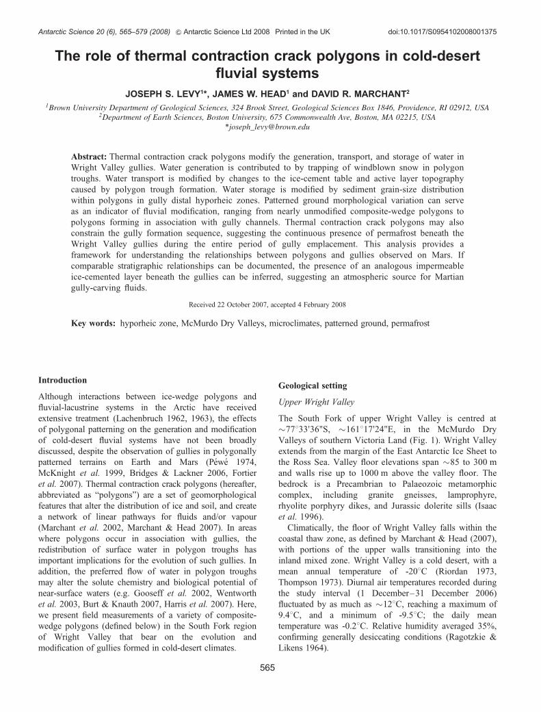
The South Fork study area is bounded to the north by theDais plateau, and to the west by a large slump block�2 km long by �600 m wide (Fig. 2). The valley floor isdominated by unconsolidated colluvium and glacial drifts;the latter are associated with advance of the Wright UpperGlacier. A seasonally moist active layer, 20–45 cm thick,overlies perennially frozen sands and gravels (pore ice, 30% by volume) (McGinnis & Jensen 1971, Head et al.2007a), and thermal contraction crack polygons arewidespread. Gullies, composed of a broad alcove, a narrowchannel, and a distal fan, are common on the south valleywall (Dickson et al. 2007, Head et al. 2007a, Levy et al.2007b, Morgan et al. 2007). Three mapped gullies occur inassociation with a broad, tongue-shaped lobe, capped bydolerite boulders, that extends from the valley rim down tothe valley floor (here termed, “the dolerite tongue”) (Fig. 2).
Morphological varieties of composite-wedge polygons
Thermal contraction crack polygons are ubiquitous in theMcMurdo Dry Valleys (Berg & Black 1966, Marchantet al. 2002). All polygons arise initially from the failure offrozen ground in response to thermal tension induced byseasonal temperature change (Leffingwell 1915, Pewe1959, Black 1982, Mellon 1997, McKay et al. 1998,Marchant et al. 2002, Marchant & Head 2007).Morphological changes thereafter are largely related tolocal microclimatic conditions: principally soil moisturedistribution, and whether or not ice, sand, or a combinationof the two fill marginal polygon troughs and underlying
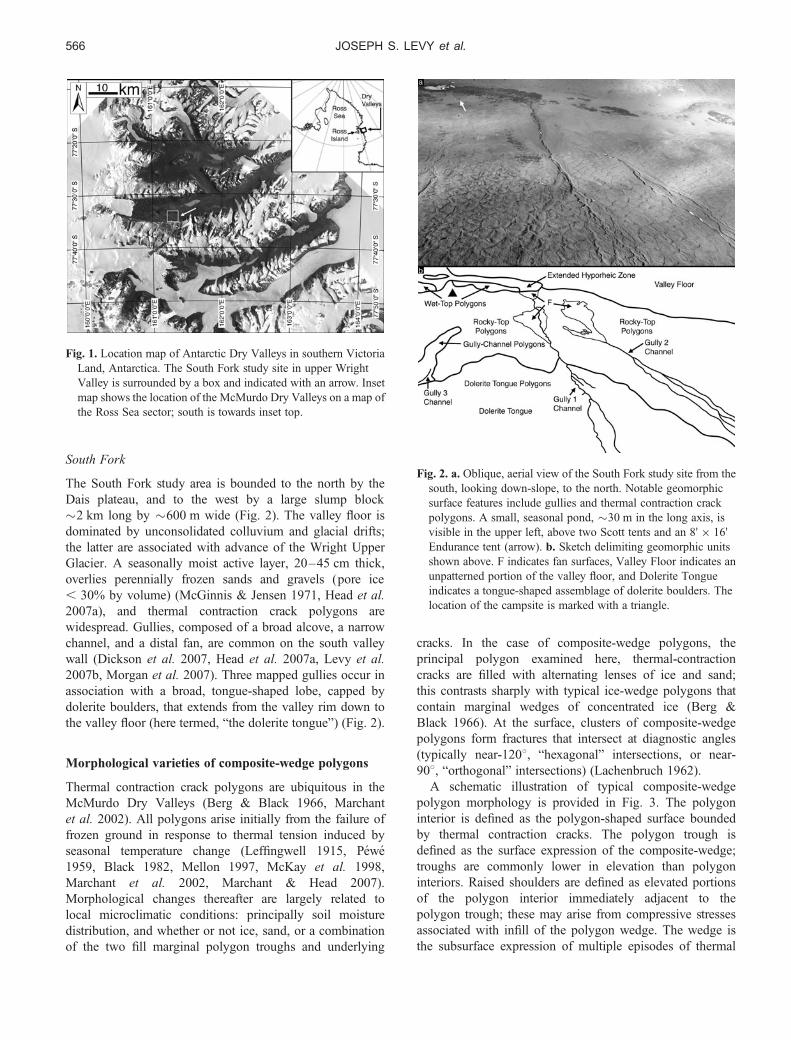
cracks. In the case of composite-wedge polygons, theprincipal polygon examined here, thermal-contractioncracks are filled with alternating lenses of ice and sand;this contrasts sharply with typical ice-wedge polygons thatcontain marginal wedges of concentrated ice (Berg &Black 1966). At the surface, clusters of composite-wedgepolygons form fractures that intersect at diagnostic angles(typically near-1208, “hexagonal” intersections, or near-908, “orthogonal” intersections) (Lachenbruch 1962).
A schematic illustration of typical composite-wedgepolygon morphology is provided in Fig. 3. The polygoninterior is defined as the polygon-shaped surface boundedby thermal contraction cracks. The polygon trough isdefined as the surface expression of the composite-wedge;troughs are commonly lower in elevation than polygoninteriors. Raised shoulders are defined as elevated portionsof the polygon interior immediately adjacent to thepolygon trough; these may arise from compressive stressesassociated with infill of the polygon wedge. The wedge isthe subsurface expression of multiple episodes of thermal
Fig. 1. Location map of Antarctic Dry Valleys in southern VictoriaLand, Antarctica. The South Fork study site in upper WrightValley is surrounded by a box and indicated with an arrow. Insetmap shows the location of the McMurdo Dry Valleys on a map ofthe Ross Sea sector; south is towards inset top.
Fig. 2. a. Oblique, aerial view of the South Fork study site from thesouth, looking down-slope, to the north. Notable geomorphicsurface features include gullies and thermal contraction crackpolygons. A small, seasonal pond, �30 m in the long axis, isvisible in the upper left, above two Scott tents and an 8’ � 16’Endurance tent (arrow). b. Sketch delimiting geomorphic unitsshown above. F indicates fan surfaces, Valley Floor indicates anunpatterned portion of the valley floor, and Dolerite Tongueindicates a tongue-shaped assemblage of dolerite boulders. Thelocation of the campsite is marked with a triangle.
JOSEPH S. LEVY et al.566
contraction crack expansion, and the subsequent winnowingdown of overlying sediments and/or meltwater, producingvertically laminated sediments mixed with ice. Furrows aredefined as shallow, linear depressions, either at the troughsurface or at the buried-ice-cement surface, indicative oflocal winnowing (in the trough) or expansion of thethermal contraction crack (in the ice-cement) by
sublimation. The ice-cement is the competent substrate inwhich thermal contraction cracking occurs, producing thepolygons. Ice-cement table depth generally follows surfacetopography. Interior material is defined as theunconsolidated regolith present at the polygon centre.
Several variations on this idealized composite-wedgepolygon morphology are present in South Fork. As shownbelow, variation reflects changes in substrate composition,surface slope, surface cover, water content, and soil catena,driven by increasing degrees of fluvial modification fromgully interactions. For each morphological variety ofcomposite-wedge polygon examined, we present adescription of its surface manifestation and its subsurfacestructure; the former derived from ground and airobservations, the latter from soil pit excavation, gravimetricwater content (“GWC”) analysis and dry sieving ofsamples. Gravimetric water content (GWC) is calculated as
Fig. 3. a. Schematic plan-view of thermal contraction crackpolygons. Polygon interiors are shaded; polygon troughs areunshaded. Typical “hexagonal” (near-1208) and “orthogonal”(near-908) trough intersections are illustrated. b. Schematic cross-section of the subsurface structure of a typical composite-wedgepolygon.
Table I. Summary of physical characteristics of composite-wedge polygon morphological varieties present in the South Fork study area.
Polygonmorphological variety
Diameter1 Trough width1 Intersection type Centre surface Trough surface
Dolerite-tonguepolygons (DTP)
12–24 m (16 m) 0.8–1.3 m(mean 1.1 m)
Near-908 Dolerite boulders and cobblesover coarse sand
Dolerite boulders and cobbles,gravitationally sorted
Rocky-top polygons(RTP)
6.5–16.5 m(11.0 m)
0.2–1.6 m(mean 0.7 m)
Mostly near-1208,some near-908
Dolerite and granite cobbles overcoarse sand
Coarse sand and small pebbles
Gully-channelpolygons (GCP)
Variable, on scale ofRTP and DTP
1–2 m, channel-dependent
Near-908 Dolerite cobbles and bouldersover medium sand, commonlybedded
Small dolerite cobbles andpebbles over medium sand
Wet-top polygons(WTP)
10–20 m (16 m) 0.2–2.0 m(mean 1.0 m)
Near-1208 Dolerite cobbles and bouldersover wet, coarse sand
Granite pebbles
1Mean value in parentheses, n ¼ 20.
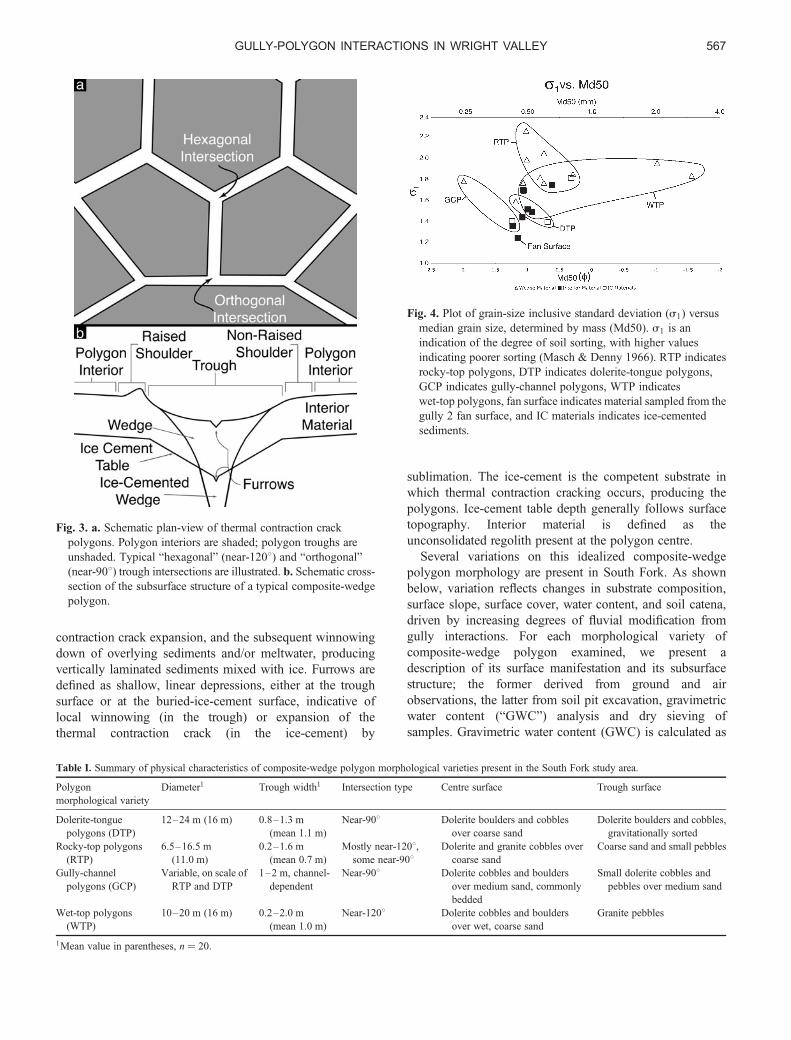
Fig. 4. Plot of grain-size inclusive standard deviation (s1) versusmedian grain size, determined by mass (Md50). s1 is anindication of the degree of soil sorting, with higher valuesindicating poorer sorting (Masch & Denny 1966). RTP indicatesrocky-top polygons, DTP indicates dolerite-tongue polygons,GCP indicates gully-channel polygons, WTP indicateswet-top polygons, fan surface indicates material sampled from thegully 2 fan surface, and IC materials indicates ice-cementedsediments.
GULLY-POLYGON INTERACTIONS IN WRIGHT VALLEY 567

the percent ratio of the mass of water in a sample to the massof the dry sample after baking at 1058C for 12 hours(Topp 1993). Grain size analyses are presented in termsof dx, where d is a grain diameter in f units (f ¼-log2[diameter in mm]) and x is the percentage of thesample finer than the given diameter, d (e.g. Sheldrick &Wang 1993). A summary of these results is found inTable I and Fig. 4.
Dolerite-tongue polygons
Composite-wedge polygons within the prominent doleritetongue at the southern edge of the study site are here termeddolerite-tongue polygons (Figs 2 & 5). Surficially, dolerite-tongue polygons are composed primarily of near-908 troughintersections, oriented down- and cross-slope, formingpolygons 12–24 m in diameter (mean diameter¼ 16 m).Dolerite-tongue polygon trough widths span 0.8–1.3 m(mean width ¼ 1.1 m) at the surface, and are commonlydepressed �30 cm or deeper (up to �1 m) relative to
Fig. 5. a. Dolerite-tongue polygons viewed from the air. Meandolerite-tongue polygon diameter is 16 m. b. Dolerite-tonguepolygons viewed from the surface. Dolerite-tongue polygontroughs have a mean width of 1.1 m. c. Schematic cross section ofa dolerite-tongue polygon.
Fig. 6. a. Aerial view of rocky-top polygons. Mean rocky-toppolygon diameter is 11 m. b. Excavation of a rocky-top polygon.The rocky-top polygon trough is oriented vertically. Rocky-toppolygon troughs have a mean width of 0.7 m. An ice-cementedcomposite-wedge is visible at centre. c. Schematic cross sectionof a rocky-top polygon.
JOSEPH S. LEVY et al.568
polygon interiors. Dolerite-tongue polygons do not showraised rims. Dolerite-tongue polygon troughs are partiallyfilled by coarse sand and pebbles, and capped by doleriteboulders, commonly at least 50 cm in diameter. Fewboulders are present along trough shoulders, suggestinggravitational sorting of larger blocks into the troughs.Shallow, 1–2 cm wide surficial axial furrows are common atthe bottom of dolerite-tongue polygon troughs, which, alongwith the presence of sand funnels, suggests current expansionof some dolerite-tongue polygon thermal contraction cracksand winnowing of underlying sediments.
Dolerite-tongue polygons have a structure similar to that oftypical composite-wedge polygons. Measured depths to theice-cement table range between 20–23 cm in dolerite-tongue polygons. Axial furrows at least 1–2 cm deep cutinto the ice-cemented portions of dolerite-tongue polygonwedges, suggesting recent fracture expansion. Overlyingthe ice-cemented sediment in both the polygon wedge andinterior (GWC ¼ 13.2%) is a layer of dark, seasonallymoist sand (GWC ¼ 11.0%) 10–15 cm thick, whichis overlain by �10 cm of dry sand (GWC ¼ 0.7%).At dolerite-tongue polygon interiors, this dry sand(d50 ¼ 0.99, d84 ¼ -0.78) is overlain by dolerite bouldersand cobbles �0.2–2 m in diameter.
Rocky-top polygons
Composite-wedge polygons present on the valley floor andlower valley walls in South Fork constitute the rocky-toppolygon variety (Figs 2 & 6). Surficially, rocky-toppolygons are composed primarily of near-hexagonal troughintersections, although some near-orthogonal intersectionsare present, forming polygons 6.5–16.5 m in diameter(mean diameter ¼ 11.0 m). Rocky-top polygon troughsspan 0.2–1.6 m in width (mean width ¼ 0.7 m) at thesurface, and are commonly depressed 5–15 cm belowpolygon interiors (being generally deeper at troughintersections and shallower mid-trough). Rows of �10 cmcobbles line some rocky-top polygon troughs, and slightlyraised shoulders (. 5 cm relief relative to rocky-toppolygon interiors) are present along some troughs. Somerocky-top polygon troughs are substantially curved in planview, having displacements of 0.5–1 m over 5 m lengthsof trough. Shallow, 1–2 cm wide axial surface furrows arecommon in rocky-top polygon troughs, which, along withthe presence of sand funnels, suggests winnowing ofsediments.
Rocky-top polygons have a relatively simple structure,similar to typical composite-wedge polygons. Measureddepth to the ice-cement table ranges between 20–30 cmin rocky-top polygons; however, ice-cemented wedgematerials can rise to within 1 cm of the surface whentroughs are filled with wind blown snow. Overlyingice-cemented rocky-top polygon interior material(GWC ¼ 3.4–4.7%) is a layer of dark, seasonally moist
sand (GWC ¼ 1.8%), which, in turn, is overlain by10–20 cm of dry sand (GWC ¼ 1.3%). Rocky-toppolygon interiors are covered by fine grained doleritecobbles (3–8 cm in diameter) and granite cobbles(commonly 10–20 cm in diameter), forming a desert
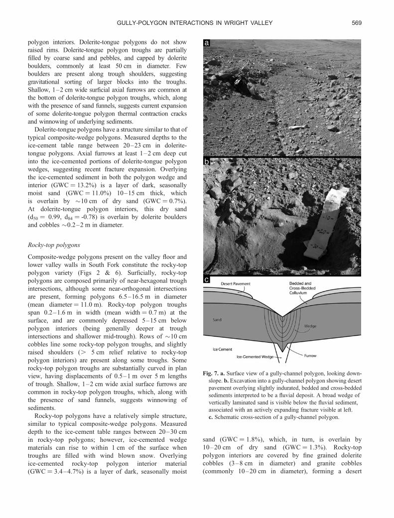
Fig. 7. a. Surface view of a gully-channel polygon, looking down-slope. b. Excavation into a gully-channel polygon showing desertpavement overlying slightly indurated, bedded and cross-beddedsediments interpreted to be a fluvial deposit. A broad wedge ofvertically laminated sand is visible below the fluvial sediment,associated with an actively expanding fracture visible at left.c. Schematic cross-section of a gully-channel polygon.
GULLY-POLYGON INTERACTIONS IN WRIGHT VALLEY 569
pavement over the dry sand (d50 ¼ 1.08, d84 ¼ -0.54). Inrocky-top polygon wedges, axial furrows 1–2 cm deepare common in the ice-cemented portion of the wedge.Overlying the ice-cemented portion of the wedge iscoarse sand to fine gravel (d50 ¼ 0.80, d84 ¼ -1.70),which is moist (GWC ¼ 2.5%) for the lower �10 cm,and dries towards the surface (GWC ¼ 1.1%). Cobblespresent in the ice-cemented, as well as in theunconsolidated portions of the wedge, are commonlyoriented vertically, suggesting in-fall or winnowingassociated with crack expansion.
Gully-channel polygons
Composite-wedge polygons present in the upper reaches ofthe channels of gullies 1–3 constitute the gully-channelpolygon morphological variety (Figs 2 & 7). Surficially,gully-channel polygons are composed primarily of near-orthogonal trough intersections, forming polygons ofcomparable diameter to rocky-top polygons and dolerite-tongue polygons. Gully-channel polygons are principallyidentified by the presence of broadened troughs (1–2 m inwidth), localized in inactive gully channels, composedof reworked colluvial material, commonly depressed10–15 cm below polygon interiors. Furrows, 5–10 cmwide and 3–5 cm deep, are common in gully-channelpolygon troughs, trending both axially and transversely tothe trough. Surface furrows suggest the recent expansion ofsome gully-channel polygon cracks and winnowing ofoverlying sediments.
Gully-channel polygon subsurface structure issignificantly different from typical composite-wedgepolygon structure. Measured depth to the ice-cementtable ranges between 20–30 cm in gully-channelpolygons. The ice-cemented portion of the wedgecommonly contains an axial furrow, 1 cm deep and 1 cmwide. Overlying ice-cemented sediment (GWC ¼ 10.4%)is a layer of dark, seasonally moist sand (GWC ¼ 3.6%)18–20 cm thick (d50 ¼ -1.16, d84 ¼ 0.11). This moistsand is overlain by 10–15 cm of dry, bedded, cross-bedded, and slightly indurated sediment (GWC ¼ 0.9%)(d50 ¼ 1.23, d84 ¼ -0.15). Dry medium to coarse sand(GWC ¼ 0.5%) occupies the upper 5 cm of gully-channel polygons (d50 ¼ -1.26, d84 ¼ 1.43). Doleritecobbles and pebbles form a desert pavement overgully-channel polygons, with clasts ranging in size from,3–10 cm in diameter over troughs, 10–100 cm indiameter over the polygon interiors.
The presence of horizontally bedded and cross-beddedsediment in broad troughs, suggests that gully-channelpolygons are relict gully channels which no longertransport water along the surface. The presence ofvertically laminated wedges beneath horizontally stratifiedfluvial sediments suggests that the polygon troughspredate the deposition of bedded sediment. The presence of
surface furrows dissecting overlying colluvium and desertpavement suggests that some gully-channel polygonfractures are currently expanding.
Wet-top polygons
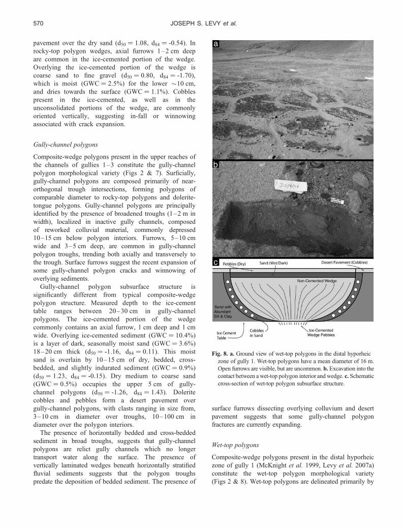
Composite-wedge polygons present in the distal hyporheiczone of gully 1 (McKnight et al. 1999, Levy et al. 2007a)constitute the wet-top polygon morphological variety(Figs 2 & 8). Wet-top polygons are delineated primarily by
Fig. 8. a. Ground view of wet-top polygons in the distal hyporheiczone of gully 1. Wet-top polygons have a mean diameter of 16 m.Open furrows are visible, but are uncommon. b. Excavation into thecontact between a wet-top polygon interior and wedge. c. Schematiccross-section of wet-top polygon subsurface structure.
JOSEPH S. LEVY et al.570
near-hexagonal trough intersections, forming polygons 10–20 m in diameter (mean diameter ¼ 16 m). Wet-toppolygon trough widths span 0.2–2.0 m (mean width ¼1.0 m) at the surface, and have little to no topographicrelief relative to polygon interiors. Axial furrows at thetrough surface are rare. A striking albedo difference marksthe surface contact between wet-top polygon troughs andinteriors, caused primarily by differences in moisturecontent. The uppermost surfaces of wet-top polygoninteriors are dark (GWC ¼ 4.6–4.9%) and wet-toppolygon trough surfaces are bright (GWC ¼ 0.3–0.4%).Some wet-top polygon interior-trough contacts are markedby a single row of �10 cm dolerite cobbles. Wet-toppolygon interiors are covered by dolerite and granitepebbles and cobbles �1–25 cm in diameter, overlyingcoarse sand to very fine gravel (d50 ¼ 1.07, d84 ¼ -1.85).
Wet-top polygons have a complex subsurface structure,resulting in part from their presence in the active hyporheiczones of the gullies. Depth to the ice-cement table rangesbetween 20–25 cm in wet-top polygons. The ice-cementedsediment in the interior of wet-top polygons is a brownish-red sand (d50 ¼ 0.92, d84 ¼ -0.66), with up to 2.2% fines(silts and clays) - the highest percentage of fines measuredin any sample analysed (GWC ¼ 8.9%). Moist, brownish-red sediment is present in wet-top polygon interiors abovethe ice-cement table (GWC ¼ 3.6–3.9%). Between wet-toppolygon interiors and wedges is a sloping assemblage ofsand and �10 cm cobbles. Axial furrows are rare in theice-cemented portion of wet-top polygon wedges, whichare composed predominantly of vertically bedded pebbles(GWC ¼ 1.4%). Uncemented wedge material is composedprimarily of light coloured pebbles, and in aggregatehas GWC ¼ 1.3–1.8%. Above wet-top polygon wedgesis a 1–2 cm thick layer of dark sediment composed of
coarse sand and pebbles (d50 ¼ 1.07, d84 ¼ -1.85)(GWC ¼ 1.0%). Wet-top polygon troughs are surfaced bylight-coloured, fine to very fine granite gravel (d50 ¼ -1.02,d84 ¼ 2.79) (GWC ¼ 0.3–0.4%).
Polygon-gully interactions
The presence of polygonally patterned ground over allcomponents of the South Fork gully systems - the alcoves,channels, and fans (Malin & Edgett 2001, Head et al.2007a) - opens up the possibility that polygons play a rolein the accumulation, transport, and storage of water ingully systems. We draw on morphological evidence to linkthe polygons described above to one or more of thesegully-forming processes.
Snow accumulation
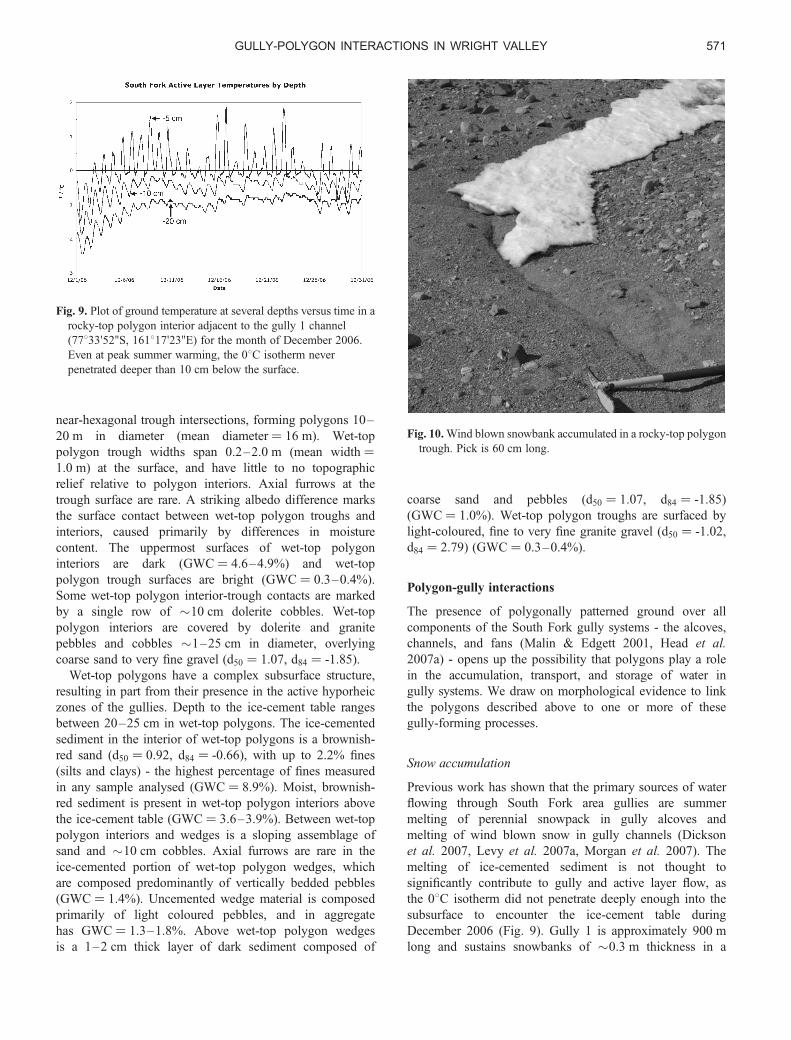
Previous work has shown that the primary sources of waterflowing through South Fork area gullies are summermelting of perennial snowpack in gully alcoves andmelting of wind blown snow in gully channels (Dicksonet al. 2007, Levy et al. 2007a, Morgan et al. 2007). Themelting of ice-cemented sediment is not thought tosignificantly contribute to gully and active layer flow, asthe 08C isotherm did not penetrate deeply enough into thesubsurface to encounter the ice-cement table duringDecember 2006 (Fig. 9). Gully 1 is approximately 900 mlong and sustains snowbanks of �0.3 m thickness in a
Fig. 9. Plot of ground temperature at several depths versus time in arocky-top polygon interior adjacent to the gully 1 channel(77833’52’’S, 161817’23’’E) for the month of December 2006.Even at peak summer warming, the 08C isotherm neverpenetrated deeper than 10 cm below the surface.
Fig. 10. Wind blown snowbank accumulated in a rocky-top polygontrough. Pick is 60 cm long.
GULLY-POLYGON INTERACTIONS IN WRIGHT VALLEY 571

Fig. 13. a. Excavation into a rocky-top polygon trough onthe southern valley wall of the study site. Upslope is tothe south, towards image top. Pick to image left is 60 cmin length. b. View into the rocky-top polygon excavationshown in part a), looking west (vantage point is near shovelblade in part a). Water is flowing out of wedge materialalong the ice-cement table beneath the rocky-top polygontrough centre, and is being channelized by the local lowcreated by the depressed ice-cement table. No flow isoccurring along the ice-cement table beneath the rocky-toppolygon interior.Fig. 12. Aerial view of a portion of the gully 1 channel. Arrows
indicate rocky-top polygon troughs which directly intersect thegully channel.
Fig. 11. a. and b. Darkened, moist trough material at the surface ofrocky-top polygon troughs intersecting the gully 1 channel.
JOSEPH S. LEVY et al.572

channel �1 m wide (Fig. 2). Assuming complete filling ofthe channel (modelled as an inverted triangular prism),�135 m3 of snow is available for melting and flow.
Wind blown snow also accumulates in the troughs ofthermal contraction crack polygons (Fig. 10). If this snowmelts over the course of the summer, it too may betransported to gully channels (see following section), andaugment gully flow (Figs 10–12). We estimated theamount of snow contributed to Gully 1 by polygons bycalculating the maximum amount of snow that could becontained in rocky-top polygon and dolerite-tonguepolygon troughs intersecting the gully 1 channel. Wemodelled the maximum dimensions of each wind blownsnowbank as an inverted triangular prism, with dimensionsequal to mean polygon trough length, width, and depth(Table I). The width and height are minimum values, assnowbanks were observed to overflow rocky-top polygontroughs. This simplified calculation estimates maximumaccumulations of �6 m3 of snow within the 30 rocky-toppolygon troughs that intersect the lower channel of gully 1,and �240 m3 of snow within the 45 dolerite-tonguepolygons intersecting the upper reaches of the gully 1channel. Thus, depending on the seasonal snow deliveryto the South Fork study area, and the distribution of thatsnow among the polygon varieties present, volumes of snowapproaching or exceeding the volume of wind blownsnow accumulated in gully channels can be contributed togully systems by the surrounding polygons.
Water transport
The presence of gully-channel polygons in the South Forkarea strongly suggests that polygons have been involved inthe transport process of water through gully systems.Previous work has shown that the ice-cement tableprovides an impermeable layer within 0.5 m of the surface,above which water can flow (Lyons et al. 2005, Headet al. 2007b, Levy et al. 2007a). What changes to thenear-surface hydraulic regime are caused by patternedground, and how do these changes affect gully activity andevolution?
Soil excavations in the South Fork study area revealedwater flowing through the active layer along the surface ofthe ice-cement table (Fig. 13). Water percolated out ofthe base of the upslope walls of these excavations, from theice-cement table to a height of � 15 cm, slowly filling theexcavation to the depth of the saturated layer, untilequilibrium was established between inflow and outflow inthe excavation. Flow was observed primarily in the activelayer beneath polygon troughs on steep slopes, and acrosspolygon troughs and interiors on shallow slopes. Watertemperatures were measured and were found to be close to08C on 31 December 2006. Slow flow rates suggest thatthis water may be saline.
Subsurface topography of the ice-cement table also plays arole in dictating water flow. Water travelling through the
active layer, along the ice-cement table beneath a polygoninterior, will eventually encounter a polygon trough.Meltwater will drain down the locally steepened ice-cementtable, toward the polygon trough, and thereafter will followthe ice-cement gradient in the trough down-slope. So longas the trough network remains generally oriented down-slope, water will remain channelled in ice-cementedpolygon troughs. Where meltwater has access to gullychannels, either by direct down-slope transport throughsingle polygon troughs, through a network of linked
Fig. 14. a. Aerial view of a section of gully 1 showing a section ofchannel kinked at close to 1208 (indicated by arrow). This type ofchannel morphology is interpreted as an indication of annexationof a pre-existing polygon trough. b. Surface view of an annexedpolygon trough. A rocky-top polygon trough enters the framefrom the lower left, bends to near-vertical at a hexagonalintersection near image centre, and bends towards the left (down-slope), exiting the frame at the upper left. A gully channel,containing surface flow, enters the frame from the lower right,encounters the polygon trough at image centre, and annexes thetrough. Flowing liquid water is present in the polygon trough atthe upper left (arrow), indicated by surface glare between smallsnow patches.
GULLY-POLYGON INTERACTIONS IN WRIGHT VALLEY 573

polygon troughs, or through lateral hyporheic zones, watercan be delivered to gully systems. Where water collects introughs that are oriented perpendicular to the down-slopedirection, water may pool, saturating the active layer, andpromoting local solifluction.
Additionally, in locations where water sources are greatenough to produce overland, or integrated overland/active-layer flow (Dickson et al. 2007, Head et al. 2007b, Levyet al. 2007a, Morgan et al. 2007), polygons may becomedirectly incorporated into evolving gullies. Where a gullychannel intersects a down-slope oriented polygon trough,meltwater flow can be transferred into the polygon trough(Figs 14 & 15). Evidence of this “annexation” of polygontroughs is based on direct observation of surface flowtravelling from gully channels into appropriately orientedpolygon troughs (Fig. 14). Supporting evidence for thisannexation also comes from the observation of stratified,waterlain sediment in gully-channel polygon troughs.Where gully channels annex polygon troughs, overland,channelized flow is observed for tens of metres, until thepolygon trough ceases to be oriented down-slope(commonly as a result of an orthogonal intersection with atrough oriented along strike). The surface flow eitherinfiltrates into the polygon interior material, or a gullychannel re-emerges, incising the polygon interior. Annexedportions of polygon troughs are generally widened and arecommonly sinuous on �1 m wavelengths. Intersectionsbetween annexed troughs and adjoining polygon troughs
are commonly rounded or bent, rather than sharp. In thismanner, polygonally patterned ground directly affects theevolution of gullies in the South Fork study area.Reciprocally, polygon trough annexation is also anexample of gully evolution modifying polygon morphology(Fig. 15).
Water storage
Water flowing through mapped gullies accumulates in distaland marginal hyporheic zones (Dickson et al. 2007, Headet al. 2007b, Levy et al. 2007a, Morgan et al. 2007),where it can affect local scale geomorphology. Bothmarginal and distal hyporheic zones are commonlysurfaced with polygons: wet-top polygons, distally (i.e. inthe down-slope direction), and rocky-top polygons,marginally.
Spatial partitioning of water in wet-top polygons isevidenced by the correlation of grain size and soil watercontent. In wet-top polygons, water is stored preferentiallyin polygon interiors, and is depleted in polygon wedges.This partitioning is interpreted to be a result of thehigher specific retention of wet-top polygon interiormaterial (on account of an unusually high fine fraction) ascompared to wet-top polygon wedge material (which has avery high pebble fraction). The presence of a fine fractionin wet-top polygon interiors, and the resulting increase inspecific retention, makes wet-top polygon interior material
Fig. 15. Schematic diagram of polygontrough annexation and water movementin gully-polygon systems. a. The initialsurface covered in thermal contractioncrack polygons. b. An eroding gullychannel encounters a polygon trough.Gully channel flow debouches into thetrough and flows through the polygontrough network. We term this processpolygon trough annexation. c. Theannexed polygon troughs widen,deepen, and become more sinuous thanneighbouring polygon troughs as thegully channel erodes the annexedtroughs. d. Polygon troughs accumulatewindblown snowbanks. Melting ofsnowbanks immediately adjacent to thegully channel provides a direct source ofwater to the gully channel. Somesnowbank meltwater infiltrates polygoninteriors; some snowbank meltwaterflows along the ice-cement tablebeneath polygon troughs until itinfiltrates a polygon interior, refreezesas part of a composite wedge, orcontributes to gully channel flow.
JOSEPH S. LEVY et al.574
an efficient storage medium for distal hyporheic zone water.Exceptionally coarse wedge material (with Md50approaching -1.6 f) suggests that the wedges may beparticularly well drained, or that enhanced communicationwith the atmosphere speeds the diffusion and evaporationof water present in the wedge. In addition, enhanced waterretention in polygon centres may help localize andfacilitate freeze-thaw processes. The latter is corroboratedby the observation of frost-heaved cobbles and smallboulders in the distal hyporheic zone and within the gully
channels during an abrupt cooling event after gully channelflow had ceased for the season.
Polygon-gully stratigraphic relationships
Did the gullies form over continuous permafrost, indicativeof climate conditions similar to present conditions, or didthey form during a warmer, and wetter set of microclimateconditions? On the basis of the stratigraphic relationshipsamong gullies and polygons, we show that patterned
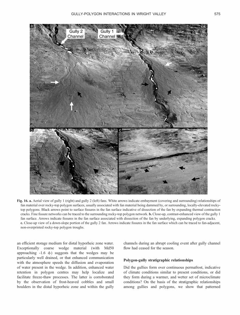
Fig. 16. a. Aerial view of gully 1 (right) and gully 2 (left) fans. White arrows indicate embayment (covering and surrounding) relationships offan material over rocky-top polygon surfaces, usually associated with fan material being dammed by, or surrounding, locally-elevated rocky-top polygons. Black arrows point to surface fissures in the fan surface indicative of dissection of the fan by expanding thermal contractioncracks. Fine fissure networks can be traced to the surrounding rocky-top polygon network. b. Close-up, contrast-enhanced view of the gully 1fan surface. Arrows indicate fissures in the fan surface associated with dissection of the fan by underlying, expanding polygon cracks.c. Close-up view of a down-slope portion of the gully 2 fan. Arrows indicate fissures in the fan surface which can be traced to fan-adjacent,non-overprinted rocky-top polygon troughs.
GULLY-POLYGON INTERACTIONS IN WRIGHT VALLEY 575
ground pre-dates, evolved concurrently with, and post-datesgully features in the South Fork study area, stronglysuggesting the continued presence of an impermeable,ice-cemented layer beneath the gully channels and fansduring the course of their formation and evolution.
Gully-channel/polygon relationships
As illustrated above, polygon troughs commonly intersectgully channels in the South Fork study area (Figs 11 &12). Determining whether the channels cross-cut thetroughs, or whether the polygon fractures formed afterchannel emplacement is essential to determine relativeages. In many locations, polygon troughs terminate in near-orthogonal intersections with gully channels. Wedge cross-sections are commonly exposed in the banks at suchlocations, but are degraded by wasting of the gully banks.Polygon fractures commonly initiate orthogonally tofluvial/lacustrine systems on account of the moderation ofthermal conditions produced by liquid water (Lachenbruch1962). However, the observation of well formed polygon
wedges exposed at these orthogonal intersections withgully channels suggests erosion of pre-existing wedges atthe channel banks, rather than pinching out of post-gullycontraction cracks. Further, in many locations, well formedpolygon troughs intersect the gully channel at non-orthogonal intersection angles. Oblique intersections arenot expected if fractures formed subsequent to channelincision. Obliquely intersecting polygon troughs commonlyoccur in areas with limited marginal hyporheic zones,suggesting that stresses associated with polygon formationwere little affected by the presence of proximate hyporheicmoisture. Further, in locations with little bank erosion,polygon troughs intersecting gully channels occur withmatching troughs present on the opposite bank of the gullychannel. There is no a priori reason to expect polygontroughs forming subsequent to gully channel incision tocommonly intersect the gully at the same location. Lastly,in some locations, the gully channels are angular andfollow polygon spacing (Fig. 14), suggesting that presentgully channels are, in locations, annexing former polygontroughs (see previous section). Taken together, these
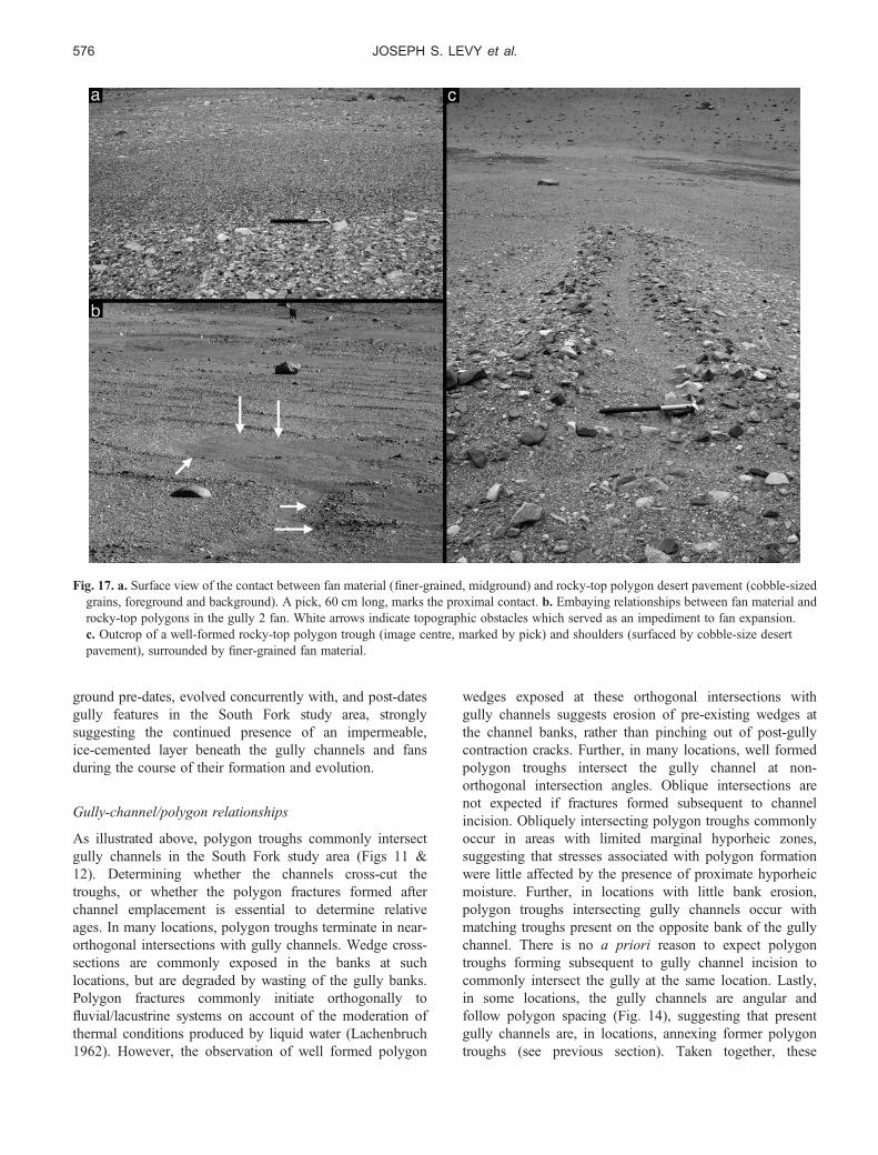
Fig. 17. a. Surface view of the contact between fan material (finer-grained, midground) and rocky-top polygon desert pavement (cobble-sizedgrains, foreground and background). A pick, 60 cm long, marks the proximal contact. b. Embaying relationships between fan material androcky-top polygons in the gully 2 fan. White arrows indicate topographic obstacles which served as an impediment to fan expansion.c. Outcrop of a well-formed rocky-top polygon trough (image centre, marked by pick) and shoulders (surfaced by cobble-size desertpavement), surrounded by finer-grained fan material.
JOSEPH S. LEVY et al.576
observations suggest that gully channel incision occurred inthe presence of thermal contraction crack polygons and thatsuitably oriented polygon troughs have been annexed byevolving gully channels.
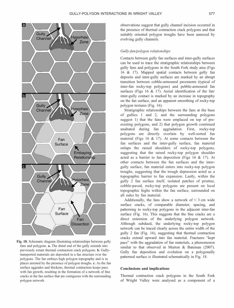
Gully-fan/polygon relationships
Contacts between gully fan surfaces and inter-gully surfacescan be used to trace the stratigraphic relationships betweengully fans and polygons in the South Fork study area (Figs16 & 17). Mapped spatial contacts between gully fandeposits and inter-gully surfaces are marked by an abrupttransition between cobble-armoured pavements (typical ofinter-fan rocky-top polygons) and pebble-armoured fansurfaces (Figs 16 & 17). Aerial identification of the fan/inter-gully contact is marked by an increase in topographyon the fan surface, and an apparent smoothing of rocky-toppolygon textures (Fig. 16).
Stratigraphic relationships between the fans at the baseof gullies 1 and 2, and the surrounding polygonssuggest 1) that the fans were emplaced on top of pre-existing polygons, and 2) that polygon growth continuedunabated during fan aggradation. First, rocky-toppolygons are directly overlain by well-sorted fanmaterial (Figs 16 & 17). At some contacts between thefan surfaces and the inter-gully surface, fan materialonlaps the raised shoulders of rocky-top polygons,suggesting that the raised rocky-top polygon shoulderacted as a barrier to fan deposition (Figs 16 & 17). Atother contacts between the fan surfaces and the inter-gully surface, fan material enters into rocky-top polygontroughs, suggesting that the trough depression acted as atopographic barrier to fan expansion. Lastly, within thegully 2 fan surface itself, isolated patches of pristine,cobble-paved, rocky-top polygons are present on localtopographic highs within the fan surface, surrounded onall sides by fan material.
Additionally, the fans show a network of , 3 cm widesurface cracks, of comparable diameter, spacing, andpatterning to rocky-top polygons in the adjacent inter-fansurface (Fig. 16). This suggests that the fine cracks are adirect extension of the underlying polygon network.Although subdued, the underlying rocky-top polygonnetwork can be traced clearly across the entire width of thegully 2 fan (Fig. 16), suggesting that thermal contractioncracks extend upward into fan material. Fractures “keptpace” with the aggradation of fan materials, a phenomenonsimilar to that observed in Murton & Bateman (2007).Gully fan deposition and evolution on a polygonallypatterned surface is illustrated schematically in Fig. 18.
Conclusions and implications
Thermal contraction crack polygons in the South Forkof Wright Valley were analysed as a component of a
Fig. 18. Schematic diagram illustrating relationships between gullyfans and polygons. a. The distal end of the gully extends intopreviously extant thermal contraction crack polygons. b. Gully-transported materials are deposited in a fan structure over thepolygons. The fan embays high polygon topography and is inplaces arrested by the presence of polygon troughs. c. As the fansurface aggrades and thickens, thermal contraction keeps pacewith fan growth, resulting in the formation of a network of finecracks in the fan surface that are contiguous with the surroundingpolygon network.
GULLY-POLYGON INTERACTIONS IN WRIGHT VALLEY 577
near-surface hydrological system in which gullies formunder cold-desert conditions. Composite-wedge polygonmorphological variations were found to form a sequence offluvial modification from largely unmodified composite-wedge polygons (dolerite tongue polygons, some rocky-toppolygons) to polygons which could only form as part of agully system (gully channel and wet-top polygons).Polygonally patterned ground in the South Fork study areawas found to play a significant role in the accumulation,transport, and storage of gully meltwater. The presence of acontinually frozen and impermeable ice-cement layer wasconfirmed, suggesting that most water present in the SouthFork region active layer is derived from summertimemelting of accumulated snow. Modification of polygonallypatterned ground surface morphology was observed, and isconsistent with accumulation and flow of water along thedepressed ice-cement table beneath polygon troughs.Gully-polygon stratigraphic relationships indicate thatpolygonal patterning preceded gully formation, andcontinued throughout gully evolution. This implies theenduring existence of climate conditions permitting thegrowth of composite-wedge polygons, and further impliesthe continuous presence of an impermeable ice-cementedsubstrate during the entire course of gully evolution.
This analysis suggests that polygon troughs represent anadditional flow path for water in the McMurdo Dry Valleyshydrological systems, both as part of an extendedhyporheic zone and as an intermediary between snowbanksand overland flow. This flow path extends the time andspace during which weathering and distillation reactionscan occur, contributing to solute load, isotopicfractionation, and the biological potential of near-surfacewaters (e.g. Gooseff et al. 2002, Harris et al. 2007).
Lastly, this analysis provides a framework forunderstanding the relationships between polygonallypatterned ground observed on gullied slopes on Mars (e.g.Bridges & Lackner 2006, Levy et al. 2007b). Ifcomparable stratigraphic relationships between Martiangully subsystems (alcoves, channels, and fans) andpolygons can be documented, then the presence of acontinuous, impermeable, ice-cemented, permafrost layerbeneath the gullies can be inferred, strongly suggesting anatmospherically derived (niveal, frost deposition, etc.)source for Martian gully-carving fluids.
Acknowledgements
This work was made possible with support of JSL by theRhode Island Space Grant Consortium, by NSF GrantANT-0338291 to DRM and JWH, and NASA MFRPGrant NNX06AE32G to DRM and JWH. Thanks to JamesDickson, Douglas Kowalewski, Gareth Morgan, DavidShean, and Kate Swanger for field support. Thanks to twoanonymous reviewers. Also, thanks to the helicopter pilots,technicians, and ground crew of PHI, Inc, as well as to
the staff of Raytheon Polar Services Company, and thepersonnel of McMurdo Station.
References
BERG, T.E. & BLACK, R.F. 1966. Preliminary measurements of growth ofnon-sorted polygons, Victoria Land, Antarctic. Antarctic ResearchSeries, 8, 61–108.
BLACK, R.F. 1982. Patterned-ground studies in Victoria Land. AntarcticJournal of the United States, 17 (5), 53–54.
BRIDGES, N.T. & LACKNER, C.N. 2006. Northern hemisphere Martian gulliesand mantled terrain: implications for near-surface water migration inMars’ recent past. Journal of Geophysical Research, 111, 10.1029/2006/JE002702.
BURT, D.M. & KNAUTH, L.P. 2007. Impacts, salts, and ice on Mars: how brineflow in young gullies and elsewhere could be related to impact cratering.In 38th Lunar and Planetary Science Conference, League City, TX.Abstract #2054, www.lpi.usra.edu/meetings/lpsc2007/pdf/2054.pdf
DICKSON, J.L., HEAD, J.W., MARCHANT, D.R., MORGAN, G.A. & LEVY, J.S.2007. Recent gully activity on Mars: Clues from late-stage water flow ingully systems and channels in the Antarctic Dry Valleys. In 38th Lunarand Planetary Science Conference, League City, TX. Abstract #1678,www.lpi.usra.edu/meetings/lpsc2007/pdf/1678.pdf.
FORTIER, D., ALLARD, M. & SHUR, Y. 2007. Observation of rapid drainagesystem development by thermal erosion of ice wedges on Byot Island,Canadian Arctic Archipelago. Permafrost and Periglacial Processes,18, 229–243.
GOOSEFF, M.N., MCKNIGHT, D.M., LYONS, W.B. & BLUM, A.E. 2002.Weathering reactions and hyporheic exchange controls on stream waterchemistry in a glacial meltwater stream in the McMurdo Dry Valleys.Water Resources Research, 38, 10.1029/2001WR000834.
HARRIS, K.J., CAREY, A.E., LYONS, W.B., WELCH, K.A. & FOUNTAIN, A.G.2007. Solute and isotope geochemistry of subsurface ice melt seeps inTaylor Valley, Antarctica. Geological Society of America Bulletin, 119,548–555.
HEAD, J.W., MARCHANT, D.R., DICKSON, J.L., LEVY, J.S. & MORGAN, G.A.2007a. Mars Gully analogs in the Antarctic Dry Valleys: geologicalsetting and processes. In 38th Lunar and Planetary Science Conference,League City, TX. Abstract #1617, www.lpi.usra.edu/meetings/lpsc2007/pdf/1617.pdf.
HEAD, J.W., MARCHANT, D.R., DICKSON, J.L., LEVY, J.S. & MORGAN, G.A.2007b. Slope streaks in the Antarctic Dry Valleys: characteristics,candidate formation mechanism, and implications for slope streakformation in the Martian environment. In 38th Lunar and PlanetaryScience Conference, League City, TX. Abstract #1935, www.lpi.usra.edu/meetings/lpsc2007/pdf/1935.pdf.
ISAAC, M.J., CHINN, T.J., EDBROOK, S. & FORSYTH, J. 1996. Geology of theOlympus Range area, southern Victoria Land, Antarctica. Wellington:Institute of Geological and Nuclear Sciences, 60 pp.
KOWALEWSKI, D.E., MARCHANT, D.R., HEAD, J.W. & LEVY, J.S. 2007.Modeling vapour diffusion in sublimation tills of the Antarctic DryValleys: implications for the preservation of near-surface ice on Mars.In 38th Lunar and Planetary Science Conference, League City, TX.Abstract #2143, www.lpi.usra.edu/meetings/lpsc2007/pdf/2143.pdf.
KOWALEWSKI, D.E., MARCHANT, D.R., LEVY, J.S. & HEAD, J.W. 2006.Quantifying low rates of summertime sublimation for buried glacier icein Beacon Valley, Antarctica. Antarctic Science, 18, 421–428.
LACHENBRUCH, A.H. 1962. Mechanics of thermal contraction cracks and ice-wedge polygons in permafrost. Geological Society of America SpecialPapers, 70, 1–69.
LACHENBRUCH, A.H. 1963. Contraction theory of ice-wedge polygons: aqualitative discussion. In International Permafrost Conference,Proceedings, Lafayette, Indiana. Washington, DC: National Academy ofSciences, National Research Council Publication, 1287, 63–71.
JOSEPH S. LEVY et al.578

LEFFINGWELL, E. DE K. 1915. Ground-ice wedges: the dominant formof ground-ice on the north coast of Alaska. Journal of Geology, 23,635–654.
LEVY, J.S., HEAD, J.W. & MARCHANT, D.R. 2005. The origin and evolution oforiented-network polygonally patterned ground: the Antarctic Dry Valleysas Mars Analogue. In 36th Lunar and Planetary Science Conference,League City, TX. Abstract #1334, www.lpi.usra.edu/meetings/lpsc2005/pdf/1334.pdf.
LEVY, J.S., HEAD, J.W., MARCHANT, D.R., MORGAN, G.A. & DICKSON, J.L.2007a. Gully surface and shallow subsurface structure in the south forkof Wright Valley, Antarctic Dry Valleys: implications for gully activityon Mars. In 38th Lunar and Planetary Science Conference, League City,TX. Abstract #1728, www.lpi.usra.edu/meetings/lpsc2007/pdf/1728.pdf.
LEVY, J.S., HEAD, J.W., MARCHANT, D.R., MORGAN, G.A. & DICKSON, J.L.2007b. Gully-polygon interactions and stratigraphy on Earth andMars: sand-wedge polygons as part of cold-desert, near-surfacefluvial systems. In Seventh International Conference on Mars,Pasadena, CA, www.lpi.usra.edu/meetings/7thmars2007/pdf/3059.pdf.
LYONS, W.B., WELCH, K.A., CAREY, A.E., WALL, D.H., VIRGINIA, R.A.,FOUNTAIN, A.G., DORAN, P.T., CSATHO, B.M. & TREMPER, C.M. 2005.Groundwater seeps in Taylor Valley, Antarctica: an example of asubsurface melt event. Annals of Glaciology, 40, 200–207.
MALIN, M.C. & EDGETT, K.S. 2001. Mars Global surveyor Mars Orbitercamera: interplanetary cruise through primary mission. Journal ofGeophysical Research, 106, 23 429–23 540.
MARCHANT, D.R. & HEAD, J.W. 2007. Antarctic Dry Valleys: microclimatezonation, variable geomorphic processes, and implications for assessingclimate change on Mars. Icarus, 192, 187–222.
MARCHANT, D.R., LEWIS, A.R., PHILLIPS, W.M., MOORE, E.J., SOUCHEZ, R.A.,DENTON, G.H., SUGDEN, D.E., POTTER, N.J. & LANDIS, G.P. 2002.Formation of patterned ground and sublimation till over Mioceneglacier ice in Beacon Valley, southern Victoria Land, Antarctica.Geological Society of America Bulletin, 114, 718–730.
MASCH, F.D. & DENNY, K.J. 1966. Grain size distribution and its effect onthe permeability of unconsolidated sands. Water Resources Research, 2,665–677.
MCGINNIS, L.D. & JENSEN, T.E. 1971. Permafrost-hydrogeologic regimen intwo ice-free valleys, Antarctica, from electrical depth sounding.Quaternary Research, 1, 31–38.
MCKAY, C.P., MELLON, M.T. & FRIEDMAN, E.I. 1998. Soil temperatures andstability of ice-cemented ground in the McMurdo Dry Valleys,Antarctica. Antarctic Science, 10, 31–38.
MCKNIGHT, D.M., NIYOGI, D.K., ALGER, A.S., BOMBLIES, A., CONOVITZ, P.A.& TATE, C.M. 1999. Dry valley streams in Antarctica: ecosystems waitingfor water. BioScience, 49, 985–995.
MELLON, M.T. 1997. Small-scale polygonal features on Mars: seasonalthermal contraction cracks in permafrost. Journal of GeophysicalResearch, 102, 25 617–25 628.
MORGAN, G.A., HEAD, J.W., MARCHANT, D.R., DICKSON, J.L. & LEVY, J.S.2007. Gully formation on Mars: testing the snowpack hypothesis fromanalysis of analogs in the Antarctic Dry Valleys. In 38th Lunar andPlanetary Science Conference, League City, TX. Abstract #1656, www.lpi.usra.edu/meetings/lpsc2007/pdf/1656.pdf.
MURTON, J.B. & BATEMAN, M.D. 2007. Syngenetic sand veins and anti-syngenetic sand wedges, Tuktoyaktuk coastlands, Western ArcticCanada. Permafrost and Periglacial Processes, 18, 33–47.
PEWE, T.L. 1959. Sand-wedge polygons (tessellations) in the McMurdoSound region, Antarctica - a progress report. American Journal ofScience, 257, 545–552.
PEWE, T.L. 1974. Geomorphic processes in polar deserts. In SMILEY, T.L. &ZUMBERGE, J.H. eds. Polar deserts and modern man. Tucson, AZ:University of Arizona Press, 35–52.
RAGOTZKIE, R.A. & LIKENS, G.E. 1964. The heat balance of two Antarcticlakes. Limnology and Oceanography, 9, 412–425.
RIORDAN, A.J. 1973. The climate of Vanda Station, Antarctica. In RAASCH,G.O., ed. Geology of the Arctic. Toronto: University of Toronto Press,268–275.
SHELDRICK, B.H. & WANG, C. 1993. Particle size distribution. In CARTER,M.R., ed. Soil sampling and methods of analysis. Boca Raton, FL:Lewis Publishers, 499–511.
SUMMERS, W.K. & WEBER, P.A. 1984. The relationship of grain-sizedistribution and hydraulic conductivity - an alternate approach. GroundWater, 22, 474–475.
THOMPSON, D.C. 1973. Climate of the Dry Valleys area of southernVictoria Land. New Zealand Geographical Society Conference Series,4, 259–265.
TOPP, G.C. 1993. Soil water content. In CARTER, M.R., ed. Soilsampling and methods of analysis. Boca Raton, FL: Lewis Publishers,541–557.
WENTWORTH, S.J., GIBSON JR, E.K. & MCKAY, D.S. 2003. Low-temperature,aqueous alteration of soil in Wright Valley, Antarctica, compared withaqueous alteration on Mars. In Third Mars Polar Science Conference,Alberta, Canada. Abstract #8128, www.lpi.usra.edu/meetings/polar2003/pdf/8128.pdf.
GULLY-POLYGON INTERACTIONS IN WRIGHT VALLEY 579