The Role of Nuclear Power and Nuclear Propulsion in … · CONTRIBUTORS TO DRAFTING AND REVIEW ......
145
The Role of Nuclear Power and Nuclear Propulsion in the Peaceful Exploration of Space
Transcript of The Role of Nuclear Power and Nuclear Propulsion in … · CONTRIBUTORS TO DRAFTING AND REVIEW ......

The Role of Nuclear Powerand Nuclear Propulsion in thePeaceful Exploration of Space

THE ROLE OF NUCLEAR POWER AND NUCLEAR PROPULSION IN THE PEACEFUL EXPLORATION
OF SPACE

The following States are Members of the International Atomic Energy Agency:
AFGHANISTANALBANIAALGERIAANGOLAARGENTINAARMENIAAUSTRALIAAUSTRIAAZERBAIJANBANGLADESHBELARUSBELGIUMBENINBOLIVIABOSNIA AND HERZEGOVINABOTSWANABRAZILBULGARIABURKINA FASOCAMEROONCANADACENTRAL AFRICAN REPUBLICCHILECHINACOLOMBIACOSTA RICACÔTE D’IVOIRECROATIACUBACYPRUSCZECH REPUBLICDEMOCRATIC REPUBLIC OF THE CONGODENMARKDOMINICAN REPUBLICECUADOREGYPTEL SALVADORERITREAESTONIAETHIOPIAFINLANDFRANCEGABONGEORGIAGERMANYGHANA
GREECEGUATEMALAHAITIHOLY SEEHONDURASHUNGARYICELANDINDIAINDONESIAIRAN, ISLAMIC REPUBLIC OF IRAQIRELANDISRAELITALYJAMAICAJAPANJORDANKAZAKHSTANKENYAKOREA, REPUBLIC OFKUWAITKYRGYZSTANLATVIALEBANONLIBERIALIBYAN ARAB JAMAHIRIYALIECHTENSTEINLITHUANIALUXEMBOURGMADAGASCARMALAYSIAMALIMALTAMARSHALL ISLANDSMAURITANIAMAURITIUSMEXICOMONACOMONGOLIAMOROCCOMYANMARNAMIBIANETHERLANDSNEW ZEALANDNICARAGUANIGERNIGERIANORWAY
PAKISTANPANAMAPARAGUAYPERUPHILIPPINESPOLANDPORTUGALQATARREPUBLIC OF MOLDOVAROMANIARUSSIAN FEDERATIONSAUDI ARABIASENEGALSERBIA AND MONTENEGROSEYCHELLESSIERRA LEONESINGAPORESLOVAKIASLOVENIASOUTH AFRICASPAINSRI LANKASUDANSWEDENSWITZERLANDSYRIAN ARAB REPUBLICTAJIKISTANTHAILANDTHE FORMER YUGOSLAV REPUBLIC OF MACEDONIATUNISIATURKEYUGANDAUKRAINEUNITED ARAB EMIRATESUNITED KINGDOM OF GREAT BRITAIN AND NORTHERN IRELANDUNITED REPUBLIC OF TANZANIAUNITED STATES OF AMERICAURUGUAYUZBEKISTANVENEZUELAVIETNAMYEMENZAMBIAZIMBABWE
The Agency’s Statute was approved on 23 October 1956 by the Conference on the Statute othe IAEA held at United Nations Headquarters, New York; it entered into force on 29 July 1957The Headquarters of the Agency are situated in Vienna. Its principal objective is “to accelerate andenlarge the contribution of atomic energy to peace, health and prosperity throughout the world’’.
f .

THE ROLE OF NUCLEAR POWER AND NUCLEAR PROPULSION IN THE PEACEFUL EXPLORATION
OF SPACE
INTERNATIONAL ATOMIC ENERGY AGENCYVIENNA, 2005

IAEA Library Cataloguing in Publication Data
The role of nuclear power and nuclear propulsion in the peaceful exploration of space. — Vienna : International Atomic Energy Agency, 2005.
p. ; 24 cm.STI/PUB/1197ISBN 92–0–107404–2Includes bibliographical references.
1. Nuclear propulsion. 2. Outer space — Exploration. I. International Atomic Energy Agency.
IAEAL 05–00413
COPYRIGHT NOTICE
All IAEA scientific and technical publications are protected by the terms of the Universal Copyright Convention as adopted in 1952 (Berne) and as revised in 1972 (Paris). The copyright has since been extended by the World Intellectual Property Organization (Geneva) to include electronic and virtual intellectual property. Permission to use whole or parts of texts contained in IAEA publications in printed or electronic form must be obtained and is usually subject to royalty agreements. Proposals for non-commercial reproductions and translations are welcomed and will be considered on a case by case basis. Enquiries should be addressed by email to the Publishing Section, IAEA, at [email protected] or by post to:
Sales and Promotion Unit, Publishing SectionInternational Atomic Energy AgencyWagramer Strasse 5P.O. Box 100A-1400 ViennaAustriafax: +43 1 2600 29302tel.: +43 1 2600 22417http://www.iaea.org/books
© IAEA, 2005
Printed by the IAEA in AustriaSeptember 2005STI/PUB/1197

FOREWORD
This publication has been produced within the framework of the IAEA’s innovative reactor and fuel cycle technology development activities. It elucidates the role that peaceful space related nuclear power research and development could play in terrestrial innovative reactor and fuel cycle technology development initiatives. This review is a contribution to the Inter-Agency Meeting on Outer Space Activities, and reflects the stepped up efforts of the Scientific and Technical Subcommittee of the Committee on the Peaceful Uses of Outer Space to further strengthen cooperation between international organizations in space related activities.
Apart from fostering information exchange within the United Nations organizations, this publication aims at finding new potential fields for innovative reactor and fuel cycle technology development. In assessing the status and reviewing the role of nuclear power in the peaceful exploration of space, it also aims to initiate a discussion on the potential benefits of space related nuclear power technology research and development to the development of innovative terrestrial nuclear systems.
The IAEA expresses its appreciation to all those who contributed to this publication, in particular to J. Graham (ETCetera Assessments LLP, United States of America), V. Ionkin (Institute for Physics and Power Engineering, Russian Federation) and N.N. Ponomarev-Stepnoi (Kurchatov Institute, Russian Federation).
The IAEA officer responsible for this publication was A. Stanculescu of the Division of Nuclear Power.

EDITORIAL NOTE
Although great care has been taken to maintain the accuracy of information contained in this publication, neither the IAEA nor its Member States assume any responsibility for consequences which may arise from its use.
The use of particular designations of countries or territories does not imply any judgement by the publisher, the IAEA, as to the legal status of such countries or territories, of their authorities and institutions or of the delimitation of their boundaries.
The mention of names of specific companies or products (whether or not indicated as registered) does not imply any intention to infringe proprietary rights, nor should it be construed as an endorsement or recommendation on the part of the IAEA.
The authors are responsible for having obtained the necessary permission for the IAEA to reproduce, translate or use material from sources already protected by copyrights.

CONTENTS
1. INTRODUCTION . . . . . . . . . . . . . . . . . . . . . . . . . . . . . . . . . . . . . . . . 1
2. REGIMES FOR THE USE OF NUCLEAR POWER IN SPACE EXPLORATION . . . . . . . . . . . . . . . . . . . . . . . . . . . . . . . . 2
3. RADIOISOTOPE POWER DEVICES . . . . . . . . . . . . . . . . . . . . . . . 7
3.1. TEGs . . . . . . . . . . . . . . . . . . . . . . . . . . . . . . . . . . . . . . . . . . . . . . . . 73.2. Thermionic converters . . . . . . . . . . . . . . . . . . . . . . . . . . . . . . . . . 133.3. Soviet/Russian TEG developments . . . . . . . . . . . . . . . . . . . . . . . 143.4. Safety . . . . . . . . . . . . . . . . . . . . . . . . . . . . . . . . . . . . . . . . . . . . . . . . 173.5. Future applications . . . . . . . . . . . . . . . . . . . . . . . . . . . . . . . . . . . . 17
4. REACTORS IN SPACE . . . . . . . . . . . . . . . . . . . . . . . . . . . . . . . . . . . . 18
4.1. US experience . . . . . . . . . . . . . . . . . . . . . . . . . . . . . . . . . . . . . . . . 184.1.1. Studies of on-board nuclear reactors . . . . . . . . . . . . . . . 20
4.2. Soviet/Russian experience . . . . . . . . . . . . . . . . . . . . . . . . . . . . . . 234.2.1. Romashka NPS . . . . . . . . . . . . . . . . . . . . . . . . . . . . . . . . . 234.2.2. BUK NPS . . . . . . . . . . . . . . . . . . . . . . . . . . . . . . . . . . . . . . 264.2.3. TOPAZ NPS . . . . . . . . . . . . . . . . . . . . . . . . . . . . . . . . . . . 294.2.4. Yenisey (TOPAZ-2) NPS . . . . . . . . . . . . . . . . . . . . . . . . . 31
5. NUCLEAR PROPULSION SYSTEMS . . . . . . . . . . . . . . . . . . . . . . . 34
5.1. US directions . . . . . . . . . . . . . . . . . . . . . . . . . . . . . . . . . . . . . . . . . 365.1.1. Safe affordable fission engine (SAFE) . . . . . . . . . . . . . . 375.1.2. Heat pipe operated Mars exploration reactor
(HOMER) . . . . . . . . . . . . . . . . . . . . . . . . . . . . . . . . . . . . . 385.2. Soviet/Russian directions . . . . . . . . . . . . . . . . . . . . . . . . . . . . . . . 40
5.2.1. IGR reactor . . . . . . . . . . . . . . . . . . . . . . . . . . . . . . . . . . . . 415.2.2. IVG-1 experimental bench reactor . . . . . . . . . . . . . . . . . 425.2.3. IRGIT reactor . . . . . . . . . . . . . . . . . . . . . . . . . . . . . . . . . . 45
5.3. Future applications . . . . . . . . . . . . . . . . . . . . . . . . . . . . . . . . . . . . 47
6. SAFETY . . . . . . . . . . . . . . . . . . . . . . . . . . . . . . . . . . . . . . . . . . . . . . . . . 48
7. OTHER INTERNATIONAL SPACE PROGRAMMES . . . . . . . . 50

7.1. China . . . . . . . . . . . . . . . . . . . . . . . . . . . . . . . . . . . . . . . . . . . . . . . . 507.2. France . . . . . . . . . . . . . . . . . . . . . . . . . . . . . . . . . . . . . . . . . . . . . . . 527.3. India . . . . . . . . . . . . . . . . . . . . . . . . . . . . . . . . . . . . . . . . . . . . . . . . 537.4. Italy . . . . . . . . . . . . . . . . . . . . . . . . . . . . . . . . . . . . . . . . . . . . . . . . . 547.5. Japan . . . . . . . . . . . . . . . . . . . . . . . . . . . . . . . . . . . . . . . . . . . . . . . . 55
8. THE FUTURE . . . . . . . . . . . . . . . . . . . . . . . . . . . . . . . . . . . . . . . . . . . . 55
8.1. Nuclear energy for interplanetary missions . . . . . . . . . . . . . . . . 558.2. International projects . . . . . . . . . . . . . . . . . . . . . . . . . . . . . . . . . . 57
8.2.1. Mars Together . . . . . . . . . . . . . . . . . . . . . . . . . . . . . . . . . . 578.2.2. TOPAZ-2 . . . . . . . . . . . . . . . . . . . . . . . . . . . . . . . . . . . . . . 57
8.3. The road ahead . . . . . . . . . . . . . . . . . . . . . . . . . . . . . . . . . . . . . . . . 608.4. USA: Future directions . . . . . . . . . . . . . . . . . . . . . . . . . . . . . . . . . 66
8.4.1. Variable specific impulse magneto-plasma rocket (VASIMR) . . . . . . . . . . . . . . . . . . . . . . . . . . . . . . . . . . . . . 68
8.4.2. Ion engines . . . . . . . . . . . . . . . . . . . . . . . . . . . . . . . . . . . . . 688.5. Russian Federation: Future directions . . . . . . . . . . . . . . . . . . . . 69
8.5.1. Transport and energy module TEM . . . . . . . . . . . . . . . . 708.5.2. Advanced thermionic NPS . . . . . . . . . . . . . . . . . . . . . . . . 718.5.3. Advanced NPSs using the external energy
conversion systems . . . . . . . . . . . . . . . . . . . . . . . . . . . . . . 748.5.4. Advanced nuclear systems using lithium–niobium
technology . . . . . . . . . . . . . . . . . . . . . . . . . . . . . . . . . . . . . 768.5.5. Gas core NTP . . . . . . . . . . . . . . . . . . . . . . . . . . . . . . . . . . 778.5.6. Nuclear photon engines for deep space exploration . . . 79
8.6. New technologies through nuclear space systems engineering . . . . . . . . . . . . . . . . . . . . . . . . . . . . . . . . . . . . . . . . . . . 80
8.7. The value of space technology in terrestrial applications . . . . . 918.7.1. Research and development . . . . . . . . . . . . . . . . . . . . . . . 918.7.2. Products, equipment and materials . . . . . . . . . . . . . . . . . 92
8.8. Problems to be solved in space by the use of nuclear power . . 98
9. CONCLUSIONS . . . . . . . . . . . . . . . . . . . . . . . . . . . . . . . . . . . . . . . . . . 101
10. LOOKING AHEAD . . . . . . . . . . . . . . . . . . . . . . . . . . . . . . . . . . . . . . . 104
APPENDIX I: EVALUATION OF MARS MISSIONS . . . . . . . . . . 107
APPENDIX II: SPACECRAFT LAUNCHES INVOLVING RADIOISOTOPE SYSTEMS . . . . . . . . . . . . . . . . . . . 108

APPENDIX III: SPACE ACHIEVEMENTS . . . . . . . . . . . . . . . . . . . . . 111
APPENDIX IV: CASSINI SPACECRAFT . . . . . . . . . . . . . . . . . . . . . . . 114
APPENDIX V: AMTEC . . . . . . . . . . . . . . . . . . . . . . . . . . . . . . . . . . . . . . 115
APPENDIX VI: PROPULSION PERFORMANCE . . . . . . . . . . . . . . . 116
APPENDIX VII: THE ROVER PROGRAMME . . . . . . . . . . . . . . . . . . 117
APPENDIX VIII: COMPARISON OF REACTOR SIZES. . . . . . . . . . . 118
APPENDIX IX: SOVIET NUCLEAR POWER SYSTEMS IN SPACE . . . . . . . . . . . . . . . . . . . . . . . . . . . . . . . . . . . 119
APPENDIX X: SPACE EXPLORATION AGENCIES AND CONTRACTORS . . . . . . . . . . . . . . . . . . . . . . . . . . . . . 121
APPENDIX XI: INTERNET REFERENCES . . . . . . . . . . . . . . . . . . . . 125
ACKNOWLEDGEMENTS . . . . . . . . . . . . . . . . . . . . . . . . . . . . . . . . . . . . . . 129BIBLIOGRAPHY . . . . . . . . . . . . . . . . . . . . . . . . . . . . . . . . . . . . . . . . . . . . . . 131CONTRIBUTORS TO DRAFTING AND REVIEW . . . . . . . . . . . . . . . . 133


1. INTRODUCTION
It is more than 100 years since the Russian theoretician Konstantin Eduardovitch Ziolkovsky advocated the use of liquid fuel rockets for space exploration and almost 80 years since Robert Hutchings Goddard launched the first liquid fuel rocket at Auburn, Massachussetts, in the United States of America. Since then, rocket development has continued apace, largely through the endeavours of experimentalists such as Goddard, Willy Ley, Hermann Oberth, Wernher von Braun and other pioneers in both the German Society for Space Travel and the American Rocket Society.
Rocket research and development was given a major boost during the Second World War when the potential of the rocket engine to provide the motive force of a long range weapon delivery system was recognized. The result was the German V-2.
The trajectory of the V-2 took it to the edge of the upper atmosphere and the border of space; it can be regarded as being the first ‘space’ rocket. Development of rocket technology gained momentum after the Second World War when both the USA and the former Soviet Union embarked on extensive programmes, culminating in the first satellite launch (Sputnik 1) in October 1957 and the first moon landing in July 1969.
Artificial satellites of necessity require their own power source. For many satellites this has taken the form of solar panels, whereby electricity is generated by the photovoltaic effect of sunlight on certain substrates, notably silicon and germanium. For satellites in earth orbit this a common method of generating power. However, the intensity of sunlight varies inversely with the cube of the distance from the sun, which means that a probe sent out to the neighbourhood of Jupiter would only receive a few per cent of the sunlight it would receive were it in earth orbit. In this case the solar panels would of necessity be so large as to be entirely impractical.
Such considerations lead to the development of alternative sources of power and heating which are completely independent of solar energy. One alternative involves the use of nuclear power systems (NPSs). These rely on the use of radioisotopes and are generally referred to as radioisotope thermo-electric generators (RTGs), thermoelectric generators (TEGs) and radio-isotope heater units (RHUs). These units have been employed on both US and Soviet/Russian spacecraft for more than 40 years. Examples of the use of these power sources on US probes over this period include Apollo, Viking, Pioneer, Voyager, Galileo, Ulysses and Cassini missions. None of these missions illustrate the utility of RTGs better than Pioneer 10, which was the first such probe to use power supplied solely from a radioisotope (238Pu).
1

Pioneer 10 was launched from Cape Kennedy on 2 March 1972. It was the first interplanetary probe, successfully navigating the asteroid belt before making rendezvous with Jupiter and Saturn. The probe was equipped with an array of instruments for measuring such phenomena as the solar wind and the magnetic and radiation fields surrounding Jupiter. In fact, its discovery of the intense radiation fields surrounding Jupiter influenced the design of the Voyager and Galileo probes. Regarding Saturn, its instruments detected another ring and discovered two new satellites, as well as measuring the planet’s magnetic field.
What was apparently the spacecraft’s last signal was received on 22 January 2003 by the Jet Propulsion Laboratory’s Deep Space Network. An attempt to contact Pioneer 10 was made on 3 February 2003, but this failed. By this time the strength of the probe’s signal had degraded to such an extent that further communication was impossible. For much of its 30-year life Pioneer 10 had been in contact with earth and during this time had transmitted valuable information on Jupiter and Saturn and the outer reaches of the solar system. It is now some 13 billion kilometres from earth.
None of this would have been possible without the use of RTGs to provide electrical power and to maintain the components’ temperatures within their operational ranges.
The use of space NPSs is not restricted to the provision of thermal and electrical power. Considerable research has been devoted to the application of nuclear thermal propulsion (NTP). Such propulsion units will be capable of transferring significantly heavier payloads into earth orbit than is currently possible using conventional chemical propellants.
This publication reviews the development of NPSs and nuclear propulsion systems used in several national space programmes and details the units’ salient characteristics and other data (Appendices I–XI). It provides a history of the missions on which they were deployed and summarizes their advantages over other systems.
2. REGIMES FOR THE USE OF NUCLEAR POWER IN SPACE EXPLORATION
A space exploration mission requires power at many stages: for the initial launch of the space vehicle and for subsequent manoeuvering; for instrumen-tation and communication systems; for warming or cooling vital systems; for lighting; for experiments and many more uses, especially in manned missions.
2

To date, chemical rocket thrusters have been used for launching. It would be tempting to believe that all power could be supplied by solar means since the sun is available and free. However, in many cases the mission may take place in the dark and large solar panels are not always suitable for a mission. Figure 1 shows the regimes of possible space power applicability.
For short durations of up to a few hours, chemical fuels can provide energy of up to 60 000 kW, but for durations of a month use is limited to a kilowatt or less. Owing to the diffuse nature of solar power, it is not practicable to provide rapid surges of large amounts of energy. On the other hand, solar power is most efficient for power levels of some 10–50 kW for as long as it is needed.
Nuclear reactors can provide almost limitless power for almost any duration. However, they are not practicable for applications below 10 kW. Radioisotopes are best used for continuous supply of low levels (up to 5 kW) of
NUCLEAR REACTORS
SOLAR RADIOISOTOPES
CHEMICAL
105
104
103
102
101
100
10-1
1 HOUR 1 DAY 1 MONTH 1 YEAR 10 YEARS
DURATION OF USE
ELE
CTR
ICA
L P
OW
ER
LE
VE
L (k
W(e
))
FIG. 1. Regimes of possible space power applicability. Source: Los Alamos National Laboratory.
3

power or in combinations up to many times this value. For this reason, especially for long interplanetary missions, the use of radioisotopes for commu-nications and the powering of experiments is preferred.
Figure 2 shows that from any nuclear process, heat is emitted. This heat can then either be converted into electricity or it can be used directly to supply heating or cooling. The initial decay produces some decay products and the use of the thermal energy will provide some additional excess thermal energy to be rejected.
The nuclear process shown in Fig. 2 can either be a critical reactor or radioisotope fuel source such as plutonium oxide. In either case the heat can be converted to electricity either statically through thermoelectrics or a thermionic converter, or dynamically using a turbine generator in one of several heat cycles (Rankine, Stirling, Brayton). A classification of potential space applications of nuclear power is shown in Table 1. The nuclear workhorses for current space missions are the RTGs and the TEGs powered by radioisotopes in the Russian Federation that provide electricity through static (and therefore reliable) conversion at power levels of up to half a kilowatt, or more by combining modules.
Nuclear reactors have also been used in space, one by the USA in 1965 (SNAP-10A) successfully achieved orbit. The former Soviet Union routinely flew spacecraft powered by reactors: 34 had been launched prior to 1989 (see Appendix IX). A Soviet position paper stated that the investigation of outer space is “unthinkable without the use of nuclear power sources for thermal and electrical energy”. The USA agreed.
FIG. 2. Generic space NPS. Source: Los Alamos National Laboratory.
4

The use of nuclear power in space is more than simply one of several power options. The choice of nuclear power can make deep space missions possible and much more efficient. For example, in a comparison between a typical chemical propulsion mission to Mars and one using nuclear propulsion, owing to the mass ratio efficiencies and the larger specific impulse1, the chemically powered mission took a planned total of 919 d and provided a stay of 454 d on the planet. By comparison, a nuclear powered mission was completed in 870 d while it provided 550 d on the planet (see Appendix I). The outward bound and return journeys
TABLE 1. CLASSIFICATION OF NUCLEAR POWER TYPES BEING CONSIDERED FOR SPACE APPLICATION (Source: Los Alamos National Laboratory)
NPS type Electrical power range (module size)
Power conversion
RTG Up to 500 W(e) Static: thermoelectric
Radioisotope dynamic conversion generator
0.5–10 kW(e) Dynamic: Brayton Organic Rankine
Reactor systems:Heat pipeSolid coreThermionics
10–1000 kW(e) Static: Thermoelectric ThermionicsDynamic: Brayton Rankine Stirling
Reactor system:Heat pipeSolid core
1–10 MW(e) Brayton Rankine Stirling
Reactor:Solid corePellet bedFluidized bedGaseous core
10–100 MW(e) Brayton (open loop)StirlingMagnetic hydrodynamic
1 The specific impulse (a measure of rocket performance and measured in seconds) is the equivalent exhaust velocity divided by the acceleration due to gravity at sea level (9.8 m/s2). The thrust (measured in Newtons or kilograms of force) is directly proportional to the specific impulse but the power needed to produce it is proportional to the square of the specific impulse.
5

took 30% less time. In the ‘map’ of possibilities involving time and a variety of payloads, nuclear power wins most of the time.
The prospects for using NPSs in space are determined by their advantages over conventional solar photovoltaic and other power sources, including:
(a) Independence of the distance to the sun and orientation with respect to the sun.
(b) Compactness (a 10 MW solar array would require solar panels that cover an area of 68 000 m2 at the distance of Mars and 760 000 m2 at Jupiter and their size would render them impracticable).
(c) Better mass and size parameters when used on unmanned spacecraft, beginning with a power level of several tens of kilowatts.
(d) The capability of providing a power level two to three times greater with the NPS mass depending relatively weakly on the power improvement.
(e) Resistance to the earth’s radiation belts.(f) The possibility of combining nuclear power with electrical thrusters to
give the highest efficiency of specific impulse for thrust and of building power/propulsion systems on this basis to allow launch of payload masses two to three times greater than those possible with conventional chemical propellant orbital boosters. This can be achieved while supplying 50–100 kW of electrical power and more for onboard instrumentation over periods of 10 years or more.
The experience accumulated in developing space NPSs, electrical thrusters and NTPSs could, in the future, enable a number of quantitatively new exploration missions, such as round the clock all-weather radar surveil-lance and global telecommunication systems, including global systems for communication with moving objects. In the future, space NPSs and combined nuclear power/propulsion systems (NPPSs) with an electrical power level of several hundred kilowatts will enable such long term space missions as global environmental monitoring, production at facilities in space, supply of power for lunar and Martian missions, and others.
As a measure of power needs in space, a space shuttle consumes about 15 kW in orbit while the International Space Station (ISS) uses 75 kW. Estimates for a Mars habitat range from 20–60 kW — not including propulsion. A baseline Mars mission would require about 10 MW, but higher power means faster transportation. Thus, a 200 MW engine could theoretically reach Mars in 39 d. Such power is only available through advanced NPSs.
6

7
3. RADIOISOTOPE POWER DEVICES
3.1. TEGS
The basic TEG is a simple device. It is based on an effect discovered by the German scientist Thomas Johann Seebeck in 1821. He found that when two dissimilar wires are connected at two junctions, and if one junction is kept hot while the other is cold, an electric current will flow in the circuit. Such a pair of junctions is called a thermocouple or thermoelectric couple.
The heat can be supplied from an isotope as in an RTG. The conversion of the heat is static. The device has no moving parts and is, therefore, very reliable and continues for as long as the radioisotope source produces a useful level of energy. The heat production is, of course, continually decaying but the radioi-sotope is custom selected to fit the intended use of the electricity and for its planned mission duration.
Figure 3 shows a hot shoe, through which radioisotopic heat is introduced, connecting the positive and negative legs. Some excess heat is rejected at the bottom and an electric current is generated.
A comparison between the predicted performance of a 150 W RTG over 12 years and its actual performance during that time is shown in Fig. 4.
RTGs have been used in 26 US and many Russian missions over the past forty years, as well as in the later French missions. They were originally installed in long term remote navigational and meteorological satellites, but RTGs have since been used in a variety of lunar and planetary missions. An RTG is a very versatile unit that can be custom designed for very specific appli-cations.
An example of an RTG SNAP is shown in Fig. 5. This is the SNAP-27 and Fig. 6 shows it being removed from the Lunar Excursion Module by astronaut Gordon Bean during the Apollo 12 mission to the moon in 1969. Five of these units were used to power experimental packages on the lunar surface. They were an ideal choice for long missions that required the supply of continuous power during both the lunar day and night. Each unit produced 63 W at the end of a year of service.
The US designed general purpose heat source (GPHS) comprises 238Pu fuel pellets encased in iridium shells (4 pellets each weighing 151 g) and 572 multiply redundant thermocouples made of silicon–germanium (see Fig. 7). Each thermocouple can produce more than half a watt. However, for other missions, different fuel and different thermocouple materials can be used. Moreover, RTGs can be used as modules of a total space auxiliary power

system for both redundancy and for total power output. For the Galileo and Ulysses space missions, which had much higher power requirements than the lunar experiments, the GPHS–RTG was designed to provide 300 W of electrical power with a nominal fuel loading of 4.4 kW. It used 18 heat source modules.
Another design, the lightweight radioisotope heater unit (RHU), is shown in Fig. 8. These units provide temperature control for sensitive electrical components. Each includes a 2.68 g 238Pu dioxide fuel pellet producing 1 W, clad in platinum–rhodium and encased in a graphite capsule for protection in the event of an accident. The Galileo spacecraft had 120 of these lightweight units in addition to its GPHS. The Galileo spacecraft was launched on
FIG. 3. Operating principle of the thermoelectric converter. Source: Rockwell International.
8

TIME (Years)
PO
WE
R O
UTP
UT
(W)
FIG. 4. Comparison between the predicted and actual performance of a 150 W RTG over a 12 year period.
HEAT REJECTION FINS OUTER CASE
HERMETIC SEAL
THERMOPILE
HOT FRAME
COLD FRAME
MOUNTING LEGS
HERMETIC SEAL
FUEL CAPSULELATCH PLATE
RADIOISOTOPEFUEL CAPSULE
FIG. 5. The SNAP-27 system. Source: NASA.
9

18 October 1989 and arrived at Jupiter on 7 December 1995. The mission was extended through 1999 to allow it to fly past Europa, Callisto and Io. These dates and the invaluable information fed back indicate the reliability of its on-board sources of thermal control and electricity generation.
Appendix II shows a listing of US and Russian spacecraft that have used RTGs (or radioisotope powered TEGs in the Russian Federation), the numbers of RTG systems and the reasons for those missions. Appendix III lists the successes of programmes supported by those power systems. These successes, with requirements for the supply of steady and reliable power for up
FIG. 6. Removal of SNAP-27 from the Lunar Excursion Module by astronaut GordonBean during the Apollo 12 mission to the moon in 1969. Source: NASA.
10

to 14 years in locations well beyond those which would allow the use of solar power, would not have been possible without RTGs.
The international2 Cassini mission to Jupiter and Saturn was equipped with 3 RTGs (see Appendix IV) which produced 885 W at the beginning of the mission and 633 W at the end. Cassini also had 82 small RHUs and there were 35 more on the Huygens probe, each producing 1 W of heat to keep nearby electronics warm. These contained a total of about 0.32 kg of 238Pu.
2 Partners: The National Aeronautics and Space Administration (NASA), the European Space Agency (ESA), the Italian Space Agency (Agenzia Spaziale Italiana – ASI) and there were a total of 17 countries involved.
FUEL CLAD
GRAPHITE AEROSHELL CAP
GRAPHITEIMPACT SHELL
CBCFDISC
LOCKMEMBER
AEROSHELL
LOCK SCREW
FLOATINGMEMBRANE
FUELPELLET
GRAPHITE IMPACTSHELL
CBCFDISC
CBCFSLEEVE
FIG. 7. GPHS module assembly. Source: US Department of Energy/General Electric Co.
11

For the future, a new advanced radioisotopic power system has been designed. It uses alkali metal thermal to electric conversion (AMTEC) technology to convert the heat produced by its plutonium heat source. The AMTEC cell (Appendix V) is made up of eight beta alumina solid electrolyte tubes connected in series. The end of the cell with the tubes is adjacent to the hot end of the heat source. At this end, liquid sodium is heated to a vapour state and the sodium atoms in the vapour are driven through the walls of the tubes and in so doing are stripped of an electron, thus creating positively charged sodium ions. The vapour is cooled and collected in a condenser at the cold end of the cell and the cycle is repeated as the sodium flows through the ‘artery’ towards the hot surface at the other end of the cell. The cell uses thermal shields in its upper section to reduce radiative bypass heat losses from the hot side components to the cold side condenser.
HEAT SHIELDEND CAP
CAPSULE
INSULATORMIDDLE TUBE
INSULATORPLUG
HEAT SHIELD
INSULATOROUTER TUBE
INSULATORINNER TUBE
INSULATORPLUG
FIG. 8. Lightweight RHU.
12

Leads are taken from the first and eighth tubes in series as the positive and negative leads for the cell. An explanatory cutaway diagram of the AMTEC system is shown in Appendix V.
This is an area of space research and development in which the latest ideas can be beneficial to various ongoing international innovative reactor technology research and development initiatives for terrestrial applications, particularly because older versions of these devices have already been used to provide power in remote situations, e.g. lighthouses and in the Arctic.
3.2. THERMIONIC CONVERTERS
Thermionic energy conversion is another method of transforming heat into electricity. It comprises a static device with a very hot emitter surface (typically at 1800 K) that ‘boils’ electrons across a small space (about 0.5 mm) to a cooler collector surface (typically at 1000 K). This action essentially creates an electrical engine with the electrons as a working fluid. There are factors preventing this engine from achieving its ultimate efficiency of the Carnot cycle. Among them are:
(a) Radiant heat transfer between the hot emitter and the cool collector;(b) Space charge effects between the plates; (c) Energy losses to the environment.
Much of the development programmes aim to overcome these difficulties. The USA had a development programme targeting a 120 kW(e) power level with lifetimes of 10 000–20 000 h (limited by heat induced effects on the materials). The programme first tested converters in the reactor core (a thermionic reactor) but this programme was terminated in 1970. Work undertaken since has addressed usage separate from the reactor, resulting in the more efficient use of both the reactor and the thermionic converter.
Thermionic diodes include fuel that is firstly surrounded by the emitter surface and secondly surrounded by the collector surface with electrical connections at the bottom to connect to the next diode in series.
A thermionic reactor does not contain fuel rods releasing heat to a coolant but thermionic fuel elements (TFEs) directly generating electricity. As with a typical reactor, the fuel is critical and is controlled by rotating control drums. The temperature of the hot emitter plates is in turn dependent upon the reactor power level. These thermionic fuel rods are packaged in series, much like torch batteries. Designs have been produced showing these TFEs to be about 2.5 cm in diameter and up to 40 cm long.
13

Gulf General Atomics tested the Thermionic Test Reactor employing carbide and oxide fuels between 1962 and 1973. Combinations of thermionic diodes and heat pipes (similar to the SP-100, see Section 4.1.1) provide challenging development problems but offer great potential.
This is another area of space research and development that can be beneficial to various ongoing international innovative reactor and fuel cycle research and development initiatives with terrestrial applications (see Section 8.7).
3.3. SOVIET/RUSSIAN TEG DEVELOPMENTS
In September 1965, TEGs (Orion-1 and Orion-2) based on 210Po were launched into a near earth orbit as components of the Cosmos-84 and Cosmos-90 satellites. The choice of 210Po (with a specific thermal power of 141 W/g and half-life of 138 d) allowed for a compact design which incorporated silicon semiconductor converters with an electrical output of ~20 W. The service life was determined mainly by the half-life of 210Po and this could reach ~3000 h.
In the mid-1970s, research and development on a complex radionuclide (radioisotope) power system using 238Pu was initiated to support long term research of Mars. This power system, named VISIT, included an RTG with an electrical power output of about 40 W, the excess heat from which was transferred to a heat exchanger by pipes. However, VISIT power system development was limited to conducting terrestrial tests of its design and the fabrication of scale models, as well as thermal and electrical prototypes. During this era, key problems connected with the creation of radioisotope powered TEGs, or RTGs, for space were solved, namely:
(a) The production and processing of the 238Pu;(b) The production of the cermet tablet fuel based on plutonium dioxide;(c) The structural materials for the manufacture of the RHU (capsules with
radionuclide), as well as their compatibility with the fuel composition over a wide temperature range;
(d) The RHU single elements’ design and the production process; (e) Bench testing of the RHU.
In 1992, a thermoelectric mock-up (using an electric heater instead of the radionuclide) with an electrical output of 3.75 W at end-of-life was fabricated and tested (see Fig. 9). Its thermal power was 100 W. The tellurium, lead and germanium based alloy semiconductors in the thermoelectric battery were
14

medium temperature ones with heat removed by thermal radiation from a ribbed casing. This RTG was proposed for use as a lander power source under ESA’s Leda lunar programme.
In the late 1990s, RTGs were used as the electrical power supply for the research probes to be landed on Mars as part of the Mars-96 international mission. The mission included long life small autonomous stations and probes (see Fig. 10). RTGs were needed to maintain equipment at design tempera-tures, to power equipment and to recharge a battery for communication with the orbiting spacecraft. Thus, 8.5 W 238Pu RHUs and a 200 mW(e) RTG named Angel were developed for the small autonomous station spacecraft. The Angel and RHU are unified products destined to be used both as self-contained units for equipment heating and as the initial heat source to provide the steady heat flow to a thermoelectric converter. The small autonomous station included two RHUs and two RTGs. The complex monoblock radionuclide power system had an electrical power output of about 400 mW and includes a storage battery, two RHUs with the thermal power of 8.5 W each and a thermoelectric converter. It was developed for the probes.
FIG. 9. Thermoelectric mock-up: (1) electric heater, (2) thermoelectric battery, (3) heat insulator, (4) casing, (5) rib. Source: Kurchatov Institute.
15

The Angel’s cylindrical heat unit (d = 4 cm, h = 6 cm) includes a heat shield case and carbon heat insulation surrounding the radioisotope’s ampoule. The ampoule contains about 17 g of 238Pu dioxide with an activity of 260 Ci. The ampoule has a dual structure. High corrosion resistant platinum–rhodium alloys are used for the inner ampoule casing that contains two ceramic tablets of 238Pu dioxide clad in iridium. The inner ampoule is hermetically welded and has a release mechanism for dealing with radiogenic helium resulting from the alpha decay of 238Pu. The load bearing outer cladding is fabricated from high strength tantalum–tungsten alloys. After hermetically welding, its surface is coated with multilayer refractory materials. Thus, the radionuclide heat source construction has a double containment in each capsule and the ampoule itself is additionally protected against outer thermal and impact attacks by heat resistant carbon materials.
The Angel radioisotope powered TEG or RTG was developed on the same basis. Semiconductor thermoelectric materials based on bismuth–telluride alloys are used as a converter. The RTG generates an electrical power of about 200 mW at an operating voltage of 15 V at room temperature. The power for the small autonomous station equipment is supplied from the RTG through a nickel–cadmium buffer battery.
SMALL STATION
RTG(2) + RHU(2)
FIG. 10. Mars-96 project: small autonomous station layout. Source: Kurchatov Institute.
16

Radioisotope powered TEGs (or RTGs) of milliwatt electrical power for space application, such as the Angel RTG and its modifications, are compact, reliable in operation and have low mass and size, which makes them convenient for probes. The RTG waste heat is enough to maintain design temperatures for equipment working in deep space environments.
Further, the RHU is also used for heating gas to warm the instrument module of the Lunokhod-1 and Lunokhod-2 stations. The heat sources’ thermal power is 900 W.
Research and development work on thermionic converters, together with the 238Pu based radionuclide heat sources, is ongoing with an emphasis being placed on improving energy conversion efficiencies from 8–10% to 10–14%. Such generators using a thermionic converter with an electrical power of 75–150 Wwere proposed as the electrical power sources for a ‘rover’ vehicle under the Leda programme.
3.4. SAFETY
The safety of all RHU applications using 238Pu must take into account normal operation, emergency conditions during the launch and an uncon-trolled descent from the circular orbit. Maintaining the 238Pu capsule airtight under all possible conditions is the basis for ensuring radiation safety. The Angel RHUs were developed and designed to be consistent with the Principles Pertaining to the Use of Nuclear Power Sources in Space that were approved by the United Nations General Assembly in 1992.
3.5. FUTURE APPLICATIONS
Although the principles of thermoelectric and thermionic heating and power devices are very simple, continued development is producing more powerful and more compact designs. These designs have many terrestrial appli-cations and therefore the research and development in this area has synergies with innovative reactor technology development activities.
17

4. REACTORS IN SPACE
As discussed in Section 2, while radioisotope powered systems are ideal for long term low power functions, nuclear reactors have the capability of producing almost unlimited power above a kilowatt for any length of mission. The USA used one in 1965 in its SNAP-10A probe and the Soviet/Russian programme has routinely used them. Thirty-four nuclear powered Soviet spacecraft were launched between 1970 and 1989.
4.1. US EXPERIENCE
Early intentions were to use nuclear reactors both to power space launches and to supply onboard power needs. Considerable research on SNAP systems led to the launch of SNAP-10A (see Fig. 11) on an Atlas launch vehicle, salient details of which are as follows:
T/E CONVERTER RADIATORS THERMOELECTRIC PUMP
EXPANSION COMPENSATOR
SUPPORT LEG
REACTOR
SHIELD
STRUCTURE 8-RING STIFFENERS
LOWER SODIUM–POTASSIUM MANIFOLD
INSTRUMENTATION COMPARTMENT
FIG. 11. SNAP-10A system. Source: Atomics International.
18

— Launch date: 3 April 1965 21:24 GMT. Launch site: Vandenberg. Launch complex: PALC2-4. Launch vehicle: SLV-3 Atlas/Agena D.
— Payload: SNAP-10A/Agena D. Mass: 440 kg. Class: Technology. Type: Ion engine. Agency: USAF/AEC. Perigee: 1270 km. Apogee: 1314 km. Incli-nation: 90.3 deg. Period: 111.4 min. COSPAR: 1965-027A. The spacecraft carried a SNAP-10A nuclear power source. The onboard nuclear reactor provided electrical power for a 1 kg force ion engine. The craft’s telemetry failed but the reactor itself operated well.
However, US Government policy changed and no more nuclear reactors were launched. Although the US sent only one nuclear reactor power source into space, the SNAP-10A, considerable work had already been done on two other reactors, SNAP-2 and SNAP-8. In the convention adopted by the USA, all RTG auxiliary power systems were denoted by odd numerals, while even numerals were reserved for nuclear reactors. All three reactors were similar but had different power levels (see Table 2).
TABLE 2. COMPARISON OF SNAP-2, SNAP-10A AND SNAP-8 REACTORS
Characteristic SNAP-2 SNAP-10A SNAP-8
Power (kW) 3 0.58 35
Design lifetime (a) 1 1 1
Reactor power (kW) 55 43 600
Reactor outlet (K) 920 833 975
Fuel and spectrum U–ZrH thermal U–ZrH thermal U–ZrH thermal
Coolant Na–K-78 Na–K-78 Na–K-78
Power conversion Rankine (Hg) Thermoelectric (Si–Ge)
Rankine (Hg)
Hot junction (K) 777
Cold junction (K) 610
Turbine inlet temperature (K)
895 950
Condenser temperature (K)
590 645
Unshielded weight (kg) 545 295 4545
19

Unsolved design issues such as mercury corrosion and crud, and protection of stator windings, bearings and the pump made the reliability of SNAP-2 and SNAP-8 potentially poor and it was for this reason that the SNAP-10A with its thermoelectric power conversion system was used in flight. The SNAP-10A power conversion system is shown in Fig. 12.
4.1.1. Studies of on-board nuclear reactors
There are many possible designs of nuclear reactors for use in space. Advanced space mission requirements for high power levels (25 500 kW(e)) coupled with compact size and long lifetimes favour the use of the fast reactor spectrum with highly enriched fuel. One design for a liquid metal cooled space reactor, which is still a major contender for the future, is shown in Fig. 13.
This design is heavily dependent upon the designs of terrestrial liquid metal cooled fast reactors but is adapted for spacecraft in which the mission is power production rather than breeding or waste reduction.
The reactor needs to be small, restrained and not dependent upon gravity for its control, which would be normal on earth. Therefore, the design uses rotating beryllium control drums that have boron carbide absorber segments.
FLOW 14.5 gpm�P 9 kPaTHERMAL POWER 1000 WAVE. RADIATOR TEMP. 583 K
ELECTRIC POWER 580 WAVE. HOT JUNCTION TEMP. 777 KAVE. RADIATOR TEMP. 610 KEFFICIENCY, CONVERSION 1.43%VOLTAGE 30 V
POWER CONVERSION SYSTEM
761 K
829 K831 K
833 K
PUMP
POWER 43 kW�P 72 K
REACTOR
FIG. 12. SNAP-10A power conversion system. Source: Atomics International.
20

However, the materials technology and proof of that technology have been completed in the non-space liquid metal fast breeder reactor programme.
This example of a distributed liquid metal cooled reactor is merely one of many candidate systems that include several variants of solid core reactors (see Table 3).
For a mass density of 30 kg/kW(e) in a small reactor, outlet temperatures must be of the order of 1200–1500 K. This temperature objective defines both the form of the fuel and the coolant. For higher power requirements, in the0.5–5.0 MW(e) range, fluidized bed and pellet bed reactors with gas cooling have been studied.
Apart from the nuclear reactor, a power plant includes shielding and a power conversion system, including converters and an excess heat rejection system.
In 1983, NASA, the US Department of Energy and several other agencies agreed to fund a joint programme, named SP-100 (see Fig. 14), to develop reactor system technology. This programme developed a power system that included a lithium cooled reactor coupled by heat pipes to thermoelectric converters. In this way the reactor could be used remotely from a manned spacecraft.
INSULATION(ZrO2)
TIE-DOWN BARS(Mo–Re)
HEAT PIPE(Mo–Re/Li)
FUEL LAYERS(UO2/Mo–Re)
DRUM BEARING
REFLECTOR (Be)
SAFETY PLUG CAP (Be) THERMAL INSULATION (MULTIFOIL)
CONTROL DRUMS (Be)
ABSORBER SEGMENT (B4C)
FUEL MODULES
RETAINER BANDS (Mo)
DRIVE SHAFT
REFLECTOR (BeO)
CORE CONTAINMENT(Mo–Re)
FIG. 13. Distributed cooled (liquid metal) space reactor. Source: Los Alamos National Laboratory.
21

The thermoelectric panels contain converters, which use heat directly radiated to the hot shoes from the heat pipes. The hot shoes are made from molybdenum or lightweight carbon–carbon composites. The thermoelectric converters are distributed throughout the panels with the cold shoes serving as the heat rejection surfaces. The whole power system would be secured to the user spacecraft by a boom running through the centre of the heat pipes. These basic technologies and their evaluation are already contributing to the future US programme.
TABLE 3. EXAMPLES OF SOLID CORE NUCLEAR REACTOR SYSTEMS
Solid core type Variant 1 Variant 2 Variant 3
Integral heat transport reactor
Matrix fuel, gaseous (He) coolant
Pin fuel, Na–Li coolant
In-core cylindrical thermionics,Na–K coolant
Distributed heat transport reactor
Heat pipewafer or coated particle fuel with heat pipes
Liquid metalwafer or coated particle fuel with electromagnetic pumps
In-core thermionicswafer or coated particle fuel with either electromagnetic pumps or heat pipes
FIG. 14. SP-100 nuclear power system (radioactively coupled system design). Source: Los Alamos National Laboratory.
22

4.2. SOVIET/RUSSIAN EXPERIENCE
The development of space NPSs with direct conversion of nuclear fission thermal power into electrical power started in the early to mid-1950s. The former Soviet Union’s first NPS with the direct (thermoelectric) conversion of nuclear fission heat into electricity was the terrestrial Romashka NPS. This NPS first operated in August 1964 and generated about 6100 kW·h of electrical energy over 15 000 h.
The BUK space thermoelectric NPS was created in the 1960s and has an electrical power output of about 3 kW. After the conclusion of tests in the early 1970s this NPS was put into operation in near earth orbits. From 1970 to 1988 there were 32 launches of these power systems (reactors) as a component of the Cosmos series of spacecraft (see Appendix IX).
The development of a space thermionic NPS was also undertaken in the early 1960s. The first successful power test of a terrestrial prototype of a thermionic reactor converter for the TOPAZ NPS was completed in 1970. Further testing over the next two decades of thermionic reactor converter prototypes and TOPAZ NPS terrestrial prototypes made it possible to test the TOPAZ in flight. The first test flights of two TOPAZ NPS models as components of the Plasma-A spacecraft (Cosmos-1818 and Cosmos-1867) took place in February and July 1987. Along with the TOPAZ NPS, the development and testing of the Yenisey thermionic NPS was started in the second half of the 1960s. Since the power, mass and size parameters of this NPS were similar to those of the TOPAZ NPS, in the West it was referred to as TOPAZ-2.
On the basis of the experience gained with first generation of NPSs (BUK, TOPAZ, Yenisey), the development of the next generation thermionic systems (NPS-25, NPS-50 (Space Star) and NPS-100) was started in the mid-1980s. The parameters of these systems meet the higher requirements in terms of the electrical power and lifetimes imposed by new space exploration targets as well as the latest safety requirements.
4.2.1. Romashka NPS
The main unit of the Romashka NPS is shown in Fig. 15. The Romashka NPS is a converter based on a fast reactor, in which the heat generated in the reactor core is conducted to a coaxially arranged TEG located on the radial reflector outer surface. The reactor core comprises a stack of 11 fuel elements; the segmented fuel elements consisting of discs of uranium bicarbide with 90% enriched 235U. This is located within a graphite package, so built that a
23

significant part of the heat from the core goes through the package body, thus reducing the temperature drop in the uranium bicarbide.
A radial beryllium reflector encloses the reactor. Graphite bushings are located between the core and the reflector to prevent reflector deformation at the high operating temperatures. The bushings are coated with silicon carbide and beryllium oxide to protect them from chemical interaction with beryllium. The reactor end reflectors are also made of beryllium. The high temperature heat insulation made of foam graphite and multilayer graphitized fabric is
FIG. 15. The Romashka NPS reactor converter layout: (1) radiator ribs, (2) thermo-electric elements, (3) control rod, (4) reactor vessel, (5) upper reflector, (6) reactor core, (7) radial reflector. Source: Kurchatov Institute.
24

mounted on the reactor end walls to reduce the heat transfer. The combination allows the reactor to operate with a temperature of up to 2173 K in the centre of the core and between 1273 K and 1373 K on the reflector outer surfaces.
The reactor control system consists of four rods located in the radial reflector and in the lower end reflector. Two rods are used for automatic and manual control, whereas the other two, together with the movable end reflector, are used for reactor protection in case of emergency.
High temperature semiconductor grade silicon–germanium alloy (Si: 85% by mass, Ge: 15% by mass) is used in the TEGs. These are mounted inside the hermetically sealed steel vessel in four groups, each group having an independent power outlet. The cell comprises two thermopiles with the n- and p-conductivity joined together on the hot side by the molybdenum keyboard. On the cold side, separate pairs are joined with each other in series by a copper bridge onto a common arm running the height of the generator.
To prevent the thermoelectric converters shorting, insulating plates of beryllium oxide are used on the hot and cold sides. To reduce heat loss, all clearances between the thermoelectric cell and hollows in the TEG structure are filled with a cotton-like quartz and a helium atmosphere. A total of 192 enamel coated fins, with an emissivity of at least 0.9, reject excess heat. Basic details of the Romashka NPS reactor converter characteristics are presented in Table 4.
TABLE 4. THE ROMASHKA NPS REACTOR CONVERTER CHARACTERISTICS
Characteristic Value
Reactor core diameter/height (by package) (mm) 241/351
Radial reflector outer diameter/height (mm) 483/553
Reactor load mass by uranium-235 (kg) 49
Total mass of the TEG (with the casing and radiator) and reactor (without drives and control rods) (kg) 635
Reactor converter effective thermal power (without taking into account the end wall spread of heat) (kW) 28.2
Reactor converter electrical output (at start-of-life) (W) 460–475
Electrical power reduction over a lifetime of 15 000 h 80%
Reactor converter terminal operating voltage (four groups of thermoelectric converters connected in series) (V) 21
Number of thermoelectric converters in a TEG 3072
25

The reactor converter generated an electric power of 460–475 W at a constant optimum outer load at start-of-life. By the end of testing (after approximately 15 000 h) the reactor converter electrical power had decreased to 80% of its initial power. This electrical power loss was mainly accounted for by an increase in the thermoelectric converter inner resistance owing to the diffusion processes operating at the graphite disc/silicon–germanium alloy interface resulting in the formation of a high resistance silicon carbide layer and, partly, to the failure of contacts on the hot side.
4.2.2. BUK NPS
The BUK NPS includes the reactor, the shielding and the conic/cylindrical radiator located in series along the axis. The radiator comprises a system of ribbed pipes for coolant flow united by input and output collectors. It is located on the load bearing frame structure that is joined to the spacecraft.
The BUK NPS uses a small fast reactor which contains 37 fuel rods. The fuel is a highly enriched uranium–molybdenum alloy; the 235U load being about 30 kg. Longitudinally movable control rods are placed in the beryllium side reflector. A two-loop liquid metal heat removal system uses a eutectic alloy of sodium and potassium as coolant. The first loop’s coolant, heated to about 973 K, is supplied to the outer casing of the TEG. The TEG, the inner cavities of which are hermetically sealed and filled with inert gas, is located under the radiator, behind the reactor shielding. The second circuit coolant removes the excess heat to the radiator with the coolant maximum temperature at the radiator inlet being about 623 K. The TEG has two independent sections: one for the spacecraft users and an auxiliary one for the power-to-conduction type electromagnetic pumps used for both coolant loops. The BUK NPS layout is shown in Fig. 16.
There are two cascade thermoelectric converters in the TEG; the first made of a high temperature alloy, the second made of a medium temperature alloy. The nuclear reactor thermal power is limited to about 100 kW, from which the maximum electrical power generated is about 3 kW, representing an efficiency of 3%. The BUK NPS lifetime was extended in operation to 4400 h by which time the electrical parameters of the TEG had degraded. The conversion efficiency at 4400 h was about 90% of its start-of-life value.
Radiation safety is provided by two diverse systems:
(1) The basic safety system, the spacecraft component, relied on moving the spacecraft into a long term burial orbit, close to circular, at a height of more than 850 km. There, nuclear reactor fission products can decay safely to the level of natural radioactivity. The orbit change system is
26

located in the spacecraft module and is mechanically joined to the nuclear power unit and separated from the spacecraft service module in low operational orbit. The orbit change system includes an off-line propulsion system with its own control systems and an off-line source of electrical power.
(2) The back-up emergency system provides for the dispersion of fuel, fission products and other materials with induced activity into the upper layers of the earth’s atmosphere. This system ejects the fuel element assembly either in the operational orbit or when the object, which includes the nuclear reactor, enters denser atmospheric layers. During the descent, aerodynamic heating, thermal destruction, melting, evaporation, oxidation, etc., are expected to disperse the fuel into particles that are sufficiently small as to pose no excess radiological hazard to the population or to the environment. This backup system consists of control devices and actuating mechanisms that deform and destroy special flexible elements by the pressure of gases from cylinders. A diagram of the fuel element assembly ejection system from the reactor core is shown in Fig. 17.
The backup safety system was introduced into the BUK NPS after the failure of Cosmos-954 spacecraft’s change of orbit system. The spacecraft’s descent resulted in large radioactive fragments of wreckage being strewn in a line across northern Canada in 1978. Characteristics of the BUK NPS are shown in Table 5.
FIG. 16. The BUK NPS layout: (1) nuclear reactor, (2) liquid metal circuit pipeline, (3) reactor shielding, (4) liquid metal circuit expansion tanks, (5) radiator, (6) TEG, (7) load bearing frame structure. Source: Kurchatov Institute.
27

TABLE 5. CHARACTERISTICS OF THE BUK NPS
Characteristic Value
Power (kW(e)) <3
Design lifetime (a) 1
Reactor power (kW) <100
Reactor outlet temperature (K) 973
Fuel and spectrum U–(90% enriched)–Mo, fast
Coolant Na–K eutectic
Power conversion Two cascade thermoelectric converter (Si–Ge)
Hot junction temperature (K) 623
Unshielded weight (kg) 900
FIG. 17. Diagram of the fuel element assembly ejection system for the BUK NPS: (1) tube plate, (2) fuel element assembly, (3) reactor vessel, (4) control rod, (5) reactor shielding, (6) side reflector, (7) actuating mechanism. Source: Kurchatov Institute.
28

4.2.3. TOPAZ NPS
The TOPAZ NPS includes a thermionic reactor converter with a caesium vapour supply system and control drum drive unit, the reactor shielding, the radiator and the frame by which the system is joined to the spacecraft service module (Fig. 18). The automatic control system is placed in the hermetically sealed service module and connected to the related nuclear power unit systems by electrical service lines.
The core consists of 79 TFEs and four zirconium hydride moderator discs. The TFEs and cooling channels are located in the moderator disc openings and form a system of five concentric rows. Five-cell TFEs with a three layer collector stack are used, with fission gas vented from emitter assemblies to the interelectrode gap. The TFEs are electrically connected so that they form the working section of 62 TFEs and the pump section of 17 TFEs. The pump section, where the TFEs are connected in parallel, is intended to energize the conduction type electromagnetic pump of the nuclear power unit’s heat removal system. The TFEs within this section are connected at both ends in the caesium vapour. The operating section terminal electrical output is about 6 kW at a voltage of ~32 V. The pumping section current is ~1200 A at a voltage of 1.1 V. Before the reactor converter is brought to the rated electrical power level, the electromagnetic pump is fed from the startup unit by a high current storage battery located behind the radiation shielding.
Twelve rotating cylinders (drums) located in the side reflector provide thermal power control, reactivity compensation and emergency shutdown.
FIG. 18. The TOPAZ NPS layout: (1) caesium vapour supply system and control drum drive unit, (2) thermionic reactor converter, (3) liquid metal circuit pipeline, (4) reactor shielding, (5) liquid metal circuit expansion tank, (6) radiator, (7) frame structure. Source: Kurchatov Institute.
29

These beryllium cylinders have sector cover plates of boron carbide and are divided into four groups of three cylinders. Each group is controlled by its own drive.
The caesium vapour supply system pumps vapour through the TFE interelectrode space at a flow rate of about 10 g/d. A pyrolized graphite trap absorbs used caesium and non-condensing impurities are ejected into space. The NPS uses a lithium hydride reactor shield located in a hermetically sealed steel container with the inner load bearing elements.
The single circuit sodium–potassium heat removal system includes a radiator that has load carrying capacity and also serves as a structural member. The radiator is designed as a system of D-shaped tubes placed hydraulically in parallel. The tubes are welded into the radiator O-ring collectors and supported by the load bearing elements. The tubes’ plane surface is soldered to a steel radiator which has a high emissivity coating. The area of the radiator is about 7 m2, which ensures rejection of at least 170 kW(th) at a coolant temperature of 880 K.
The automatic system controls the NPS to rated thermal and electrical power levels, maintains the working section current or coolant temperature at the rated level, maintains the voltage of ~28 V for the on-board equipment supply lines and can provide shutdown of the thermionic reactor converter.
A high speed controller that redistributes the direct current of the thermionic reactor converter section between the spacecraft and ballast loads controls the voltage. In the nominal operating mode, the rated current of the operating section and, consequently, its electrical power are sustained by correcting thermal power. As the efficiency degrades the coolant temperature rises to 880 K. After that, instead of maintaining the current, the automatic control system limits the coolant temperature. The thermal power then remains practically constant, whereas the operating section current will fall to values at which the onboard network voltage exceeds allowable limits, requiring NPS shutdown. NPS shutdown is also provided for specific emergency situations, as well as by radio command from earth.
The TOPAZ NPS generates approximately 6 kW at a start-of-life efficiency of about 5.5%. Its mass, including the nuclear power unit, the automatic control system and the coupling service lines, is about 1200 kg and it has a design lifetime of 4400 h. The nuclear power unit is 4.7 m long with a maximum diameter of 1.3 m.
In the period 1982–1984, two power tests of the TOPAZ NPS in combination with the automatic control system were performed in the automatic mode to prepare for flight tests. The first of these was performed with TFEs using emitter assemblies of single crystal molybdenum with a single crystal tungsten coating; the second with TFEs using single crystal
30

molybdenum emitter assemblies. The first of the units was tested to ~4500 h and the second to ~7000 h. Results of testing fully corroborated the control algorithms in startup and operating modes, as well as agreeing with output parameters of the NPS, its subsystems and components and electrical power of no less than 5.6 kW for the prescribed lifetime of 4400 h.
In 1987, two experimental Plasma-A satellites (see Fig. 19) were launched with new generation TOPAZ reactors.
Safety was provided during the TOPAZ tests by placing the spacecraft in a circular operational orbit at a height in excess of 800 km. This orbit would provide sufficient decay time (350 a) for radioactive materials and fission products. The reactor was only made critical once the safe orbit had been attained. Details are summarized as follows:
— 2 February 1987 Cosmos-1818 Programme: Radar Ocean Reconnaissance Satellite RORSAT. Launch Site: Baikonur. Launch Vehicle: Tsyklon 2. Mass: 3800 kg. Perigee: 790 km. Apogee: 810 km. Inclination: 65.0o.
— 10 July 1987 Cosmos-1867 Programme: RORSAT. Launch Site: Baikonur. Mass: 3800 kg. Perigee: 797 km. Apogee: 813 km. Inclination: 65.0o.
The NPS used with the first of the spacecraft (Cosmos-1818) operated for 142 d and the second one (Cosmos-1867) for 342 d. In both cases the NPS operation was terminated as planned when the caesium stock was exhausted.
The test programme objectives were fulfilled for both units. The flight test results confirmed the TOPAZ NPS output parameters and that operation in terrestrial conditions agreed with those in space. They attested to the stable operation of the reactor converter and its support systems in space flight and in the presence of operating plasma thrusters.
4.2.4. Yenisey (TOPAZ-2) NPS
Figure 20 shows a general view of the Yenisey NPS. All the equipment is packaged within a single unit referred to as the reactor or head unit, which has the shape of a truncated cone. The reactor is at the top, with the radiation
FIG. 19. Plasma-A satellite. Source: Kurchatov Institute.
31

shielding located immediately underneath and all other equipment arranged in the shielding ‘shadow’.
The TOPAZ and Yenisey NPSs have similar structures and design arrangements. The principal difference between them is that the Yenisey thermionic reactor converter employs a single unit TFE; the emitter unit having an outer diameter of 19.6 mm and the collector pack an outer diameter of 23.7 mm (versus 10.0 mm and 14.6 mm, respectively, for TOPAZ). The main characteristics of the Yenisey NPS are presented in Table 6.
A single crystal molybdenum alloy with a single crystal tungsten 184 coating is used as the emitter material and the polycrystalline molybdenum alloy is used as the collector material. The emitter units have a central orifice through which the gaseous fission products are to be ejected into space. The TFEs are located in the thermionic reactor converter core tubes.
FIG. 20. General view of the Yenisey NPS. Source: Kurchatov Institute.
32

The small clearance between the TFE and the tube is filled with helium. In the reactor core there are 37 TFEs with the O-ring channels for their cooling located in orifices in zirconium hydride moderator discs. The operating section consists of 34 TFEs, the pumping section consisting of three. The electrical
TABLE 6. MAIN CHARACTERISTICS OF THE YENISEY NPS
Description Value
Maximum electrical power at the reactor unit terminals supplied to consumer (kW) 5.5
Current type Direct
Voltage (V) 27
Reactor thermal power (kW(th)) 135
Maximum coolant temperature at the reactor outlet (°C) 550
Maximum emitter temperature (°C) 1650
Lifetime corroborated by nuclear tests (a) 1.5
Reactor unit mass (kg) 1000
Dimensions of the reactor unit: Length (mm) 3900 Maximum diameter (mm) 1400
Radiation situation over a plane of diameter 1.5 m at 6.5 m from the core centre: Fluence of neutrons with energy >0.1 MeV (n/cm2 ) 5 × 10¹² Gamma radiation exposure dose (R) 5 × 10⁵
Core diameter (mm) 260
Core height (mm) 375
Number of TFEs in the core 37
Number of rotational control elements in the side reflector 12
Loading of uranium-235 in the core (kg) 25
Effective neutron multiplication factor (control elements out, cold state) (keff) 1.005
Total reactivity temperature effect (Dk/k) 0.012
Worth of 12 control elements (Dk/k) 0.055
Peak to average power density: Along to the core radius 1.1 Along to the core height 1.26
Lifetime ensured by the reactivity margin 3
33

power on the operating section terminals can vary through a range from 4.5 kW to 5.5 kW at about 30 V.
The Yenisey NPS, as does the TOPAZ, employs a one circuit heat removal system with a conduction type electromagnetic pump powered in startup by a heavy current storage battery.
The NPS has a design mass of 1000 kg and a lifetime of 1.5 a. It is 3.9 m long and has a maximum diameter of 1.4 m.
The Yenisey NPS went through a whole cycle of terrestrial tests, including the off-line test of the various units and systems, mechanical and thermal physical tests of full-scale mock-ups, and tests of a number of pre-launch preparatory processes and NPS prototypes. Testing was performed using electrical heaters in place of nuclear fuel.
Six terrestrial nuclear power tests were performed between 1975 and 1986, the three final tests being for 12 500, 8000 and 4700 h. All TFEs preserved their full working capacity and their electrical characteristics were stable within ±3%.
The thermionic reactor converter operating section provides 4.5 kW at an efficiency of about 4.5%. The tests were stopped owing to a loss of integrity of the liquid metal circuits. No Yenisey NPS flight tests were made.
5. NUCLEAR PROPULSION SYSTEMS
Nuclear power can be used for a rocket propulsion system. The reactor power is used to heat a propellant that is forced through the rocket nozzle to provide motion in the opposite direction. Figure 21 shows a typical nuclear rocket propulsion module.
Two parameters that provide a measure of the efficiency of a rocket propulsion energy source are the theoretical specific impulse and the ratio of the take-off mass to the final mass in orbit. As shown in Appendix VI, chemical reaction using hydrogen, oxygen or fluorine can achieve a specific impulse of 4300 s with a mass ratio for earth escape of 15. However, hydrogen heated by a fission reactor instead of a chemical reaction achieves twice the specific impulse with a solid core while at the same time having a mass ratio of 3.2. With different cores, the specific impulse can be as much as seven times greater again with a mass ratio of only 1.2.
The fundamental advantage of NTP units over liquid propellant rocket engines lies in being able to use a single component working fluid with the
34

minimum molecular weight, which, all other factors being equal, provides a maximum specific impulse. Thus, when using hydrogen the specific impulse produced by NTP can be more than twice as high as that of chemical engines.
Owing to its higher specific impulse, NTP can perform the same space mission with a smaller mass of propellant than a chemical engine. On a purely theoretical basis it is possible to do even better with direct fission, or thermo-nuclear fusion, with theoretical impulses rising to 36 × 106 s and a mass ratio that is barely larger than unity.
PROPELLANTTANK
PROPELLANTFEED PUMP
NUCLEAR REACTORHEAT EXCHANGER
BLEED TURBINEDRIVE
HEATED PROPELLANT
FIG. 21. Typical nuclear rocket propulsion module. Source: NASA/US Department of Energy.
35

5.1. US DIRECTIONS
The basic improvement in mass ratio to be obtained from a nuclear fission propulsion system was recognized very early on. In the USA, a test programme named Rover was conducted from 1955 to 1973 using various designs. Appendix VII lists the achievements that culminated in 1969 in the XE-prime engine (see Fig. 22), a first down firing prototype operating at 1100 MW. In 1972, a 44 MW nuclear furnace demonstrated peak fuel power densities of 4500 MW/m3 with temperatures of up to 2500 K for 109 min. Appendix VIII shows a comparison of the sizes of reactors tested in the Rover programme.
The nuclear rocket programme, which cost $1.7 billion ($7 billion in current dollars), was considered a technical success but it was terminated and the US programme has since used chemical propellants. However, nuclear
FIG. 22. The ground experimental engine (XE-prime) installed in Engine Test Stand No. 1 at the Nuclear Rocket Development Station in Nevada. Source: NASA.
36

propulsion may be the option of choice for a manned mission to Mars according to recent conference announcements. Indeed, a 1990 assessment of the programme concluded that a Mars mission could be performed with NERVA technology [2].
5.1.1. Safe affordable fission engine (SAFE)
Another concept, SAFE, is a propulsive heat pipe power system on which work is being done at the Los Alamos National Laboratory and the Marshall Space Flight Center. SAFE-400 (see Fig. 23) is designed to provide 400 kW of thermal power for more than ten years through two independent Brayton power systems, the reactor heat being deposited into the gas (He 72%, Xe 28%) flow via two independent heat pipe to gas heat exchangers. This provides 100 kW(e) for a 25% efficiency.
SAFE-400 axial dimensions:
Fuelled length = 56 cmBeO axial refelector length = 4 cmFission gas plenum length = 5 cmTotal fuel pin length = 70 cm
Radial reflector length = 62 cmControl drum length = 56 cm
Heat exchanger plenum length = 5 cm (4x)
Heat exchanger heated length = 25 cm (2x)
Heat exchanger gaps = 2.5 cm (3x)Heat pipe length = 145 cm
FIG. 23. The SAFE-400 reactor. Source: Nuclear News.
37

The SAFE-400 reactor contains 127 identical modules made of niobium–zirconium (1 wt%) alloy. Each module contains a Nb1Zr–Na heat pipe at its centre surrounded by three niobium–zirconium tubes each of which contains a rhenium clad uranium nitride fuel sleeve. The wick of the heat pipe is fabricated from Nb1Zr mesh; the 60% void being filled with sodium during operation. The heat pipes extend 75 cm outside the core. The fission power is transferred to the heat pipes at a vapour temperature of 1200 K and, thence, to the Brayton cycle heat exchangers.
The system uses existing technology and can be tested with electrical heating in existing facilities, so development time is short. It is also flexible since it can be used with Stirling or Brayton cycles. Furthermore, it is designed to be passively safe in all credible launch or re-entry accident scenarios. For example, it is subcritical even if fully immersed and surrounded by wet sand. Moreover, it is designed so that no operations are required after launch to prepare it for startup. In operation, the reactor is controlled by Nb1Zr clad beryllium control drums which have a boron carbide absorber layer.
The mass of the reactor is 512 kg. This could be reduced to as little as 80 kg if changes in design parameters and operations are made. However, in all cases of reduced dimensions and different control configurations, the relia-bility, safety margins, ease of fabrication and ease of integration would be reduced. Thus, the mass is a compromise between greater safety and increased reliability.
The technology has been tested in heat pipe demonstrations and with a 12 module SAFE-30 core. Also, the SAFE-400 has been tested through the 19 module SAFE-100 programme, which is of similar design but where the Nb1Zr has been replaced by stainless steel for economy. The programme also tested fabrication techniques. The integrated core and heat exchanger were tested in 2003 in a new facility at the Marshall Space Flight Center.
5.1.2. Heat pipe operated Mars exploration reactor (HOMER)
Getting to Mars may be the attainment of a primary objective but for a person to survive on the surface a source of electrical energy is needed. Approximately 3–20 kW(e) are required, which just takes the task beyond the capabilities of an RTG because of the mass of plutonium required. Solar power is impractical because of the distance of Mars from the sun and for seasonal and geographic sunlight issues. Thus, nuclear fission is the remaining option. HOMER is shown in Fig. 24.
HOMER fulfils the need for a small power source. It is designed specifi-cally for producing electricity on the surface of the planet. The low power
38

requirement means that the reactor operates within well-understood regimes of power density, burnup and fission gas release. The fluence is so low that there is no significant irradiation damage to core materials.
HOMER-15 is a 15 kW(th) reactor designed to couple with a 3 kW Stirling engine via heat pipes. Since the system is low power, it can be considered a module of a larger array should more power be needed.
The reactor uses 102 uranium nitride fuel pins, each 44 cm long, clad in 316 stainless steel, cooled by 19 stainless steel–sodium heat pipes and assisted by the 0.38g Martian gravity. The heat pipes extend 40 cm beyond the core axial shield to a heat exchanger. There, the heat is transmitted to a Stirling cycle engine.
REACTOR CONTROLDRIVES
STIRLING ENGINE
VIBRATION DAMPER
LOOP HEAT PIPESTO RADIATOR
HEAT EXCHANGER
REACTOR AXIALRADIATION SHIELD
REACTOR ANDHEAT PIPES
2.4 m
FIG. 24. The HOMER power source. Source: Nuclear News.
39

5.2. SOVIET/RUSSIAN DIRECTIONS
The 1950s were the years when individual groups of specialists in the former Soviet Union initiated innovative research to work on NTP.
It is possible to create a rocket with a nuclear engine. As shown earlier, this engine can provide a specific impulse 2–2.5 times higher than chemically fuelled engines. For this specific impulse and the needed mass and size charac-teristics, hydrogen must be heated in the engine reactor to a mass average temperature of 3000 K. The specific power flux in the reactor core would be 30 kW/cm3.
In the Russian programme, a heterogeneous reactor layout is used with the neutron moderator located separately from the uranium fuel elements. The fuel elements are surrounded by heat insulation and enclosed in the metal casing forming the complete independent reactor unit — the fuel assembly. This preference for a heterogeneous reactor and element by element testing was a fundamental difference between the Russian and US programmes.
The fuel assembly is the basic unit of a heterogeneous propulsion reactor. In the assembly the working fluid is heated to the temperatures required to meet the specific impulse of the design.
A typical reactor design (Fig. 25) includes: the cooled power casing (which can end with a nozzle), the fuel assembly core itself, the high
WORKING MEDIUMSUPPLY
CONTROL DRUM DRIVE
CONTROL DRUM
FUEL ASSEMBLY
COMBUSTION CHAMBERBOTTOM
NOZZLE CHAMBER
TURBO-DRIVENPUMP ASSEMBLY
REACTOR SHIELDING
MODERATOR
REACTOR VESSEL
NOZZLE COOLINGMAIN LINE
NOZZLE
FIG. 25. Russian NTP system (conceptual design). Source: Kurchatov Institute.
40

temperature heat insulation, the bearing unit, the inlet unit (which provides the uniform working fluid supply to the fuel assemblies and which can contain a temperature compensation device) and the end reflector and protection elements. The essence of the concept is a nuclear reactor with a heterogeneous core comprised of individual fuel assemblies (including fuel elements based on uranium, zirconium and niobium carbides) located in the zirconium hydride moderator body. The beryllium reflector, the shadow radiation shielding and the hydrogen loop surround the core. Radiation shielding is included for manned missions.
Fuel requirements include:
(a) High density of uranium per unit volume of fuel;(b) High resistance to radiation swelling; (c) High corrosion resistance to the working fluid; (d) A maximum allowable temperature of the working fluid; (e) A maximum number of the heating–cooling cycles; (f) Properties that provide passive safety.
The most acceptable fuel compositions meeting these requirements are solid solutions of carbides (UC–ZrC, UC–NbC, UC–TaC) with a uranium density of ~2 g/cm3. This fuel would provide a temperature of 3300 K for heating the hydrogen propellant.
The NTP parameters were first verified experimentally in the course of conducting fuel assembly simulator tests in the IGR reactor and subsequently the fuel assemblies and the reactor core units were tested in the IVG-1 reactor.
Also, for the Russian NTP programmes (i.e. all three concepts described in Sections 5.2.1, 5.2.2 and 5.2.3), it should be noted that this is an area of space research and development that can be beneficial to various ongoing interna-tional innovative reactor and fuel cycle research and development initiatives for terrestrial applications (see Section 8.7).
5.2.1. IGR reactor
The IGR reactor (1961) allowed research to be undertaken on fuel and assembly materials under full-scale operational conditions. The fuel assembly to be tested was mounted in the central experimental channel of the reactor inside a water cooled ampoule type metal structure. Fuel elements and fuel assemblies of varying design were tested in the reactor.
The purposes of these tests in the IGR reactor were to:
41

(a) Check the reliability of selected materials and protective coatings of fuel elements in hydrogen at temperatures between 3000 and 3300 K in a high neutron and γ irradiation environment;
(b) Substantiate optimum steady state operational temperatures of the fuel elements;
(c) Check fuel assembly structural elements and units, as well as the methods of construction and assembly of heat insulation materials;
(d) Obtain data on specific fuel assembly parameters, in particular, the specific thrust impulse;
(e) Obtain data on the dynamic characteristics of fuel assemblies and optimal modes of control;
(f) Investigate fuel assembly operating peculiarities, in particular, to determine the amount of the uranium and fission fragments released into the hydrogen.
Following the loop tests, full-scale fuel assembly tests were conducted in a reactor under steady state operation.
5.2.2. IVG-1 experimental bench reactor
Apart from testing fuel assemblies and reactor core elements with various characteristics, the IVG-1 experimental reactor was destined to function as a bench prototype of a medium power (200–400 kN of thrust) NTP unit.
The design of the 720 MW IVG-1 reactor is such that full-scale tests of fuel elements and fuel assemblies of various types with a varying range of power (thrust) can be made. An individual supply of the gaseous hydrogen to each fuel assembly allows tests at rated gas outlet temperatures, while the use of a water moderator makes it possible to vary the fuel assembly cross-section dimensions and power. The IVG-1 reactor has allowed testing of fuel assembly groups with a thrust of up to 40 t and of a single fuel assembly in a loop at thrusts of up to 200 t.
The IVG-1 reactor is a heterogeneous gas cooled reactor using a water moderator and a beryllium reflector. It consists of both permanent and replaceable sections. The permanent sections are shown in Fig. 26. The replaceable core sections include the central assembly which comprises a set of thirty test channels and the central channel. The test fuel assemblies can be placed in either the test channel units or in the central channel. As the central channel is embedded in the beryllium displacer, the thermal neutron flux in the channel can be approximately twice the average cross-sectional flux of thermal neutrons, making it possible to test the fuel assembly mounted in the central channel to failure.
Figure 26 ((a) and (b)) shows the IVG-1 reactor cross-section and the sectional view, respectively.
42

FIG. 26(a). The IVG-1 reactor cross-section.
FIG. 26(b). The IVG-1 reactor sectional view. Source: Kurchatov Institute.
43

The IVG-1 reactor made it possible to:
(a) Confirm the selection of the structural materials used for the fuel elements and assemblies early on;
(b) Confirm the reliability of the fuel assembly designs in hydrogen within specified limits;
(c) Study the physics and thermal–physical characteristics of the fuel assemblies and core elements;
(d) Study the dynamic properties of the fuel elements and assemblies.
Successful test performance of the fuel assemblies in the IVG-1 reactor made it possible to start the next test stage — conducting off-line tests of the reactor (see Fig. 27). In bench tests the reactor generated a thrust of 36 kN; the
FIG. 27. Startup of the IVG-1 experimental reactor (thermal power: 225 MW; hydrogen temperature: 3000 K). Source: Kurchatov Institute.
44

tests being carried out using the IRGIT reactor, the specially designed prototype of the NTP reactor.
5.2.3. IRGIT reactor
The IRGIT reactor tests included the following stages: reactor physical startup; cold gas dynamic tests; physical startup check; cold hydrodynamic tests; powered startup; fuel fired tests and post-test research.
The physical startup was undertaken in two stages: the first at the Strela test facility at the Institute for Physics and Power Engineering and the second at the Baikal-1 test bench complex (now situated at Kurchatov in Kazakhstan). Transferring the system between two sites gave a valuable insight into the mechanical effects of the first set of tests.
For reasons of safety and economy, the cold hydrodynamic tests were carried out using a substitute for the working fluid (nitrogen).
Powered startup, as distinct from physical startup, brings the reactor to a power level that is sufficient to heat the reactor structure and the working medium to a value close to the nominal design value (or a little lower). Figure 28 shows the IRGIT reactor at the Keldysh Center Test Facility Berth.
The main purposes of the fuel fired tests were to provide a compre-hensive check of the serviceability of the reactor and its units and a check of the engineering and design solutions. The following research was performed during the fuel fired test:
(a) The thermal and hydraulic characteristics of the reactor structural elements were studied, including measurement of temperature fields and hydrogen pressure distribution in the moderator, reflector and fuel assemblies; study of startup and shutdown after cooling; and investigation of the condition of the fuel assemblies and other reactor units and systems after the test.
(b) Neutron physics characteristics were measured, including the reactivity margin, the temperature, power and density parameters of reactivity effects and the dynamic characteristics of the reactor and control system.
(c) The quantities of uranium and fission products released from the fuel assemblies were defined and the reactor shielding efficiency and inner (on the bench test complex site) and outer radiation fields investigated.
(d) Operation of the test bench equipment and systems was studied.
45

The IRGIT reactor went through two series of fuel fired tests in July and August 1978. Table 7 presents some rated duty parameters measured during the powered startup and fuel fired tests of the first NTP reactor test series.
Subsequently, full-scale tests of two more IRGIT reactor configurations were carried out on the Baikal-1 test bench complex. The analysis of test results and post-test studies showed that the basic reactor units, including test fuel assemblies, successfully withstood the tests at the rated parameters and remained in good condition afterwards.
At the same time, a number of operational faults in separate units and systems of a reactor were detected. The study of emergent thermal stresses was not completed because of the low reactor power, which meant that the
FIG. 28. The IRGIT reactor at the Keldysh Center Test Facility Berth. Source: Kurchatov Institute.
46

moderator unit serviceability limits were not defined (the reactor temperature measurement system selected turned out to be insufficiently informative). The fuel characteristics achieved confirmed that it was possible to design compact reactor cores with varying power output to provide an NTP specific impulse of more than 900 s.
5.3. FUTURE APPLICATIONS
The space research and development carried out in both the former Soviet Union/Russian Federation and the USA can provide great benefits to comparable research and development on innovative reactor concepts and fuel cycles currently being conducted under international initiatives. In particular, the use of heat pipes in the SAFE-400 and HOMER units has not yet been pursued for small terrestrial reactors. Also, the research and development of
TABLE 7. PARAMETERS MEASURED DURING THE POWERED STARTUP AND FUEL FIRED TESTS OF THE NTP REACTOR FIRST TEST SERIES
Parameter Poweredstartup
Fuel firedtest 1
Fuel firedtest 2
Power (MW) 24 33 42
Rated duty duration (s) 70 93 90
Flow rate of working medium (kg/s) through: Vessel–reflector–moderator Fuel assemblies
1.721.18
3.231.46
3.512.01
Working medium average temperature at the fuel assembly outlet (K) 1670 2630 2600
Working medium pressure (MPa) at: Reactor vessel inlet Fuel assembly inlet Fuel assembly outlet
6.04 1.9 1.1
9.46 2.2 1.2
10.65 2.4 1.3
Material average temperature (K): Moderator units Reflector units Reactor vessel (from the outside)
405356315
397381320
398371325
Flow rate of water for cooling of device process arm (kg/s) 8 8.3 8.3
47

extremely strong materials to withstand harsh environments could be beneficial for deep ocean or polar use.
6. SAFETY
Safety, both for astronauts as well as for the public, has been a prime concern of the space programme. Both RTGs and TEGs, the workhorse auxiliary power systems, have several levels of inherent safety:
(1) The fuel used is in the form of a heat resistant ceramic plutonium oxide that reduces the chances of vaporization in the event of a fire or during re-entry. Further, the ceramic is highly insoluble and primarily fractures into large pieces rather than forming dust that could be inhaled. These characteristics reduce any potential health effects if the fuel were released.
(2) The fuel is divided into small independent modules each with its own heat shield and impact casing. This reduces the chance that all the fuel would be released in any accident.
(3) There are multiple layers of protective containment, including capsules made of material such as iridium, located inside high strength heat resistant graphite blocks. The iridium has a melting temperature of 4449 K which is well above re-entry temperatures. It is also corrosion resistant and chemically compatible with the plutonium oxide that it contains.
However, one accident did occur on 21 April 1964 when the failure of a launch vehicle resulted in the burnup of the SNAP-9A RTG during re-entry. This resulted in the dispersion of plutonium in the upper atmosphere. It was as a result of this accident and the consequent redesign of the RTGs that the current level of safety has been provided.
A second accident occurred on 18 May 1968 after a launch at Vandenberg Air Force Base was aborted. The SNAP-19 heat sources were found off the coast at a depth of 100 m. They were recovered intact with no release of plutonium. The fuel was removed and used in a later mission.
A third accident occurred in April 1970 when the Apollo 13 mission aborted. The lunar excursion module, including a SNAP-27 RTG, re-entered the atmosphere and plunged into the ocean close to the Tonga Trench, sinking to a depth of between six and nine kilometres. Monitoring since then has shown no evidence of any release of fuel.
48

The former Soviet Union routinely flew spacecraft that included nuclear reactors in low earth orbits. At the end of a mission, the spacecraft was boosted to a higher, very long lived orbit so that nuclear materials could decay naturally.
There was a major accident on 24 January 1978 when Cosmos-954 could not be boosted to a higher orbit and re-entered the earth’s atmosphere over Canada. Debris was found along a 600 km tract north of Great Bear Lake. No large fuel particles were found but about 4000 small particles were collected. Four large steel fragments that appeared to have been part of the periphery of the reactor core were discovered with high radioactivity levels. There were also 47 beryllium rods and cylinders and miscellaneous pieces, all with some contamination.
As a result of this accident, the Russian Federation redesigned its systems for backup safety. Further, a United Nations Working Group has developed aerospace nuclear safety design requirements whereby:
(a) The reactor shall be designed to remain subcritical if immersed in water or other fluids, such as liquid propellants (or wet sand);
(b) The reactor shall have a significantly effective negative power coefficient of reactivity;
(c) The reactor shall be designed so that no credible launch pad accident, ascent, abort, or re-entry from space resulting in earth impact could result in a critical or supercritical geometry;
(d) The reactor shall not be operated (except for zero power testing that yields negligible radioactivity at the time of launch) until a stable orbit or flight path is achieved and it must have a re-boost capability from low earth orbit if it is operated in that orbit;
(e) Two independent systems shall be provided to reduce reactivity to a subcritical state and these shall not be subject to a common failure mode;
(f) The reactor shall be designed to ensure that sufficiently independent shutdown heat removal paths are available to provide decay heat removal;
(g) The unirradiated fuel shall pose no significant environmental hazard;(h) The reactor shall remain subcritical under the environmental conditions
of the postulated launch vehicle explosions or range of safety destruct actions.
Thus, as in all advances of technology, experience tells. The accident of Cosmos-954, which fortunately resulted in no danger to humans because of the remoteness of its crash area, had the effect of improving the safe design of nuclear reactor powered spacecraft.
49

Each country has used these international rules and some have expanded them to meet their own requirements. As an example, in 1998 the Russian Federation published a policy governing safety and recovery.
7. OTHER INTERNATIONAL SPACE PROGRAMMES
While the former Soviet Union/Russian Federation and the USA have had extensive space programmes based on rocket programmes of the 1920s and 1930s, other nations have established successful space programmes in the past three decades: Australia, Austria, Brazil, Canada, China (including Taiwan, China), Denmark, France, Germany, India, Italy, Japan, Netherlands, Norway, Spain, Sweden, Turkey, Ukraine and the United Kingdom all have space agencies, as has Europe (ESA).
Many of these countries and groups are maintaining a watching brief while others are participating in US and Russian programmes, sometimes as part of ESA. Others are going it alone in conducting or participating in the burgeoning commercial business of launching all manner of communication and surveillance satellites. For example, Europe has been launching cooperative international satellites from Vandenberg Air Force Base in California, Woomera in South Australia and Cape Canaveral in Florida, since at least 1968; on the other hand Canada has launched its own satellites from Vandenberg since 1969.
Most, if not all, of the cooperative programmes launch telecommuni-cation and meteorological satellites into earth orbit and use solar arrays to power the communications once the satellite is in stable orbit. There is no need for the types of power system needed for extremely long mission times or for missions close to the sun (needing cooling) or far from it (needing heating). Thus, no nuclear reactors have been used and the use of RTGs is minimal.
7.1. CHINA
China’s space programme started in 1959 and its first satellite, Dongfanghong-I, was successfully developed and launched on 24 April 1970, making China the fifth country in the world with such capability.
By October 2000, China had developed and launched 47 satellites of various types, with a flight success rate of over 90%. Altogether, four satellite series have been initially developed by China: recoverable remote sensing
50

satellites; Dongfanghong telecommunications satellites; Fengyun meteoro-logical satellites; and Shijian scientific research and technological experiment satellites. The Ziyuan earth resource satellite series will be launched in the very near future. China is the third country in the world to have mastered the technology of satellite recovery, with a success rate reaching an advanced inter-national level, and it is the fifth country capable of independently developing and launching geostationary telecommunications satellites. By 2001, China’s capability with regard to the development of meteorological and earth resource satellites had reached the international level of the 1990s. The six telecommuni-cation, earth resource and meteorological satellites developed and launched by China in the past few years are in stable operation and have generated remarkable social and economic returns.
China also has a vigorous programme (Shenzhou) aimed at developing a manned spacecraft. The unmanned Shenzou IV space capsule orbited the earth for seven days in December 2002. Figure 29 shows the Shenzou-2 space capsule. Prime contractors for the Shenzhou programme are the China Research Institute of Carrier Rocket Technology (part of the China Aerospace
FIG. 29. The Shenzou-2 space capsule. Source: Chinese Aerospace and Technology Corporation.
51

Science and Technology Corporation), the Chinese Research Institute of Space Technology and the Shanghai Research Institute of Astronautical Technology. Also involved in the design and testing of the spacecraft are the Chinese Academy of Sciences and the Ministry of Information Industry.
Zhuang Fenggan, vice-chairperson of the China Association of Sciences, declared in October 2000 that one day the Chinese would create a permanent lunar base with the intention of mining the lunar soil for helium-3 (to fuel nuclear fusion plants on earth).
7.2. FRANCE
The Astérix technological capsule was the first French satellite placed into orbit by Diamant, launched from the Hammaguir base in southern Algeria on 26 November 1965. In 1968, an independent launch site at Kouros in French Guiana started operation with the launch of a Véronique probe.
France now has both a cooperative manned space explorationprogramme and a domestic business of launching satellites for other nations. The heart of the national programme is the Ariane series of launchers, which since 1994 has completed an average of ten launches per year — 90 to the end of 2002.
France’s strategic space programme to 2010 makes note of the following objectives:
(a) A Mars exploration programme, in partnership with the USA, focusing chiefly on a Mars sample return mission (one of the major technical and scientific challenges for space exploration in the early 21st century);
(b) Exploration of objects such as comets and asteroids to learn more about the structure of the primordial solar system;
(c) Exploration of distant planets to understand their features and climates better.
Manned exploration has so far been limited to cooperation with the ISS effort. There are no declared objectives for using nuclear power in future French space programmes. The only power objective noted is in the more efficient use of focused solar power.
52

7.3. INDIA
India launched its first satellite, INSAT-1, in 1990 and its second, INSAT-2A, in 1992. These early satellites were launched using the Ariane launch vehicle from Kouros in French Guiana. The second satellite had a seven year mission to provide communications and meteorological surveillance. Five more similar satellite launches were made prior to mid-2002. Four scientific satellites in the IRS series have been launched from Sriharikota in India, SROSS-C2 is another scientific series for topographical mapping.
PSLV, the latest multisatellite vehicle, launched from Satish Dhawan Space Centre on the east coast of India, has also been used to launch other nation’s satellites (Belgium, Germany, Republic of Korea). The PSLV-C3 launcher (with three satellites) uses a combination of solid and liquid propellants. The four stages are as follows:
(1) The first stage is one of the largest solid propellant boosters in the world and carries 138 t of hydroxyl terminated polybutadiene (HTPB) propellant. It has a diameter of 2.8 m. The motor case is made of maraging steel. The booster develops a maximum thrust of about 4430 kN. Six strap-on motors, four of which are ignited on the ground, augment the first stage thrust. Each of these solid propellant strap-on motors carries 9 t of HTPB propellant and produces 677 kN of thrust.
(2) The second stage employs the Vikas engine and carries 40 t of liquid propellant (unsymmetrical dimethyl hydrazine) as fuel and nitrogen tetroxide (N2O4) as oxidizer. It generates a maximum thrust of 724 kN.
(3) The third stage uses 7 t of HTPB based solid propellant and produces a maximum thrust of 324 kN. Its motor case is made of Kevlar epoxy fibre.
(4) The fourth and terminal stage of the PSLV has a twin-engine configu-ration using liquid propellant. With a propellant loading of 2 t (monomethyl hydrazine plus mixed oxides of nitrogen), each of these engines generates a maximum thrust of 7.4 kN.
While a larger vehicle (GSLV-D1) has completed a developmental flight, there is no intention to use nuclear propellants since all the missions are in earth orbit with durations of 7 years or more. Satellites are equipped with solar panels.
53

7.4. ITALY
Italy was one of the first European nations to operate its own earth satellite (launched by the USA in 1964). Through the ASI, established in 1988, Italy is also a contributor to the ESA programmes. There is also careful consid-eration being given to nuclear powered deep space exploration. The following is an example given in a press release from late 1998 by Discovery-on-Line:
“‘A nuclear-powered engine could someday shorten a spacecraft’s journey to Mars from three years to only 45 days.’ That’s according to Professor Carlo Rubbia, winner of the 1984 Nobel Prize for Physics. He says his brainchild could open the way to a systematic exploration of our planetary system by humans. ‘Nuclear energy on Earth is competing with many other alternatives and is not without problems, but in deep space travel it offers unique possibilities’ says Rubbia, introducing his project during a 1998 conference at CERN, the European particle physics laboratory in Geneva. Indeed, nuclear energy seems to be the innovative ingredient in any recipe for deep space exploration, though none of the propulsion tools considered so far has been able to offer a quick ticket to Mars. With his so-called fission fragment rocket, Rubbia claims he has finally found the solution. Fission fragments are the direct products of a nuclear reaction in which a nucleus is split into fragments, accompanied by a release of energy.”
Rubbia’s engine is based on this process and on a key element — 242Am. A chemical element somewhat similar to lead, americium was first separated from 239Pu in 1944. The combustion chamber of Rubbia’s engine would be covered with a thin layer of 242Am whose fission, induced by neutrons, produces highly ionized fragments. The process continues with hydrogen entering the chamber. The fission fragments pass through hydrogen and the resulting heat creates a powerful propellant. The energy supplied by 1 g of americium is about the same as that of 1 t of the best chemical propellant. A few kilos of americium would be sufficient for the 194 million km voyage to Mars for a spacecraft and its crew.
Rubbia’s light and simply structured spacecraft would allow round trip travel to Mars in a maximum of five months, including the necessary stay on the planet.
“I’m in touch with the Italian and the European space agencies for a possible realization (development) of the engine” says Rubbia. “For Europe this would mean a leading role in future space explorations.”
54

7.5. JAPAN
Japan has had an indigenous space programme from early on. A successive series of launch vehicles have been produced starting with the N1 launched from the Tanegashima Space Center in 1975.
SELENE (SELenological and ENgineering Explorer) will be the first large lunar probe made in Japan. It was developed in the first ISAS/NASDA joint lunar programme and was launched by the H-11A vehicle in 2003. The major objectives of the mission are to acquire scientific data on the origin and evolution of the moon and to develop the technology for future lunar explo-ration. The scientific data will also be used for exploring the possibility of future utilization of the moon. A major Japanese endeavour is the Kibo exper-imental space module which will conduct a number of experiments. The module will be supported from the ISS. To date no nuclear reactors or RTGs have been used in the Japanese programme.
8. THE FUTURE
Future space missions will require high power sources. An overview of future missions and their corresponding power requirements is given in Fig. 30.
8.1. NUCLEAR ENERGY FOR INTERPLANETARY MISSIONS
The use of nuclear energy can dramatically change the capabilities of interplanetary spacecraft. When compared with chemical propulsion systems currently used for interplanetary missions for example, nuclear electrical propulsion systems (representing a combination of an NPS and electrical propulsion) will provide significant progress. First, nuclear electrical propulsion will give a significantly higher acceleration and/or allow delivery of a heavier payload or the use of a cheaper launch vehicle, and second, it will permit the use of a straight trajectory with simple flight programmes without gravitational manoeuvres, with reduced times of flight as well as wider launch windows.
55

As a result, nuclear electrical propulsion systems can be used to overcome the existing energy barriers and to implement radically new science projects. For exploration of the outer planets (at a distance greater than 5 au3), nuclear energy has no competitors since the power of solar cells is reduced to unacceptable levels in these regions. To satisfy near term requirements, about 30–100 kW will be needed for both transportation and research. Thus, power and propulsion for such spacecraft can only be ensured by means of nuclear power.
Moreover, if nuclear energy is used, the duration of most missions even to the remotest parts of the solar system will not exceed 10 years, and no more than 5 years for missions closer than Jupiter.
3 An astronomical unit (au) is the mean distance between the earth and the sun and is approximately 149.6 × 10⁶ km.
102
103
104
105
10
REQUIRED POWER LEVELS (kW)
COMMUNICATIONS AND TV BROADCASTING
ENVIRONMENT PROTECTION MISSIONS
SCIENCE MISSIONS
POWER GENERATION AND PRODUCTION PROCESSES IN SPACE
GLOBAL SPACE MISSIONS
High capacity satellite communication systems Global systems for communications with mobile objects High performance global information systems Direct TV broadcasting, high resolution multichannel TV
Radioactive waste disposal Global environment monitoring Cleaning of anthropogenic refuse from
near earth space Spacecraft protection from space debris
Space production processes Remote power supply to spacecraft and
space production facilities
Basic research, including studies usinga space radio telescope Earth exploration from space
Exploration of asteroids, comets
and solar system planetsTranspiration and engineering supportto a lunar base
Mars mission Power supply to the earth from space Lighting of limited areas on the earth Resource production on asteroids Destruction of cores of emerging typhoons Prevention of collisions with asteroids and comets Restoration of the earth's ozone layer Transfer of hazardous production processes to space Greenhouse effect control
FIG. 30. Future high power demand space missions. Source: Kurchatov Institute.
56

It is believed by many experts that, for many reasons, the NPS concept of using a thermionic reactor/energy converter is the most practicable for this type of mission. The nearest competitor in terms of the level of readiness is an NPS which employs a dynamic turbine cycle of energy conversion that offers a higher energy potential and requires fewer developments in technology.
Introduction of nuclear energy in space applications can be accelerated if this is done on the basis of international cooperation. At the moment, the circumstances are favourable for such interactions. Anticipated NASA activities aimed at implementing US Government initiatives may correlate well with Russian activities in the field of space nuclear power. This provides a good foundation for cooperation. The future, hopefully, will witness the same level of international cooperation as that demonstrated in the building and use of the ISS.
8.2. INTERNATIONAL PROJECTS
The following projects exemplify the sort of collaborative planning that has been achieved to date on projects other than the ISS.
8.2.1. Mars Together
In 1994–1995, RKK Energia and NASA’s Jet Propulsion Laboratory analysed the project Mars Together. This evaluation studied the use of spacecraft equipped solar arrays or nuclear reactors to supply power of up to 30–40 kW needed for insertion into Martian orbit and operation of a sideways-radar to map the surface digitally. As a preliminary step, a demonstration launch was proposed of a spacecraft with a mass of 120–150 kg, a solar panel area of 30 m2 and engines with a thrust of 3 kN. One of the objectives of the experiment would be to gain an understanding of the change in orbital altitude with continuous operation of the ion engine over several hundred hours.
Both nations have remarkably similar approaches and it therefore makes sense to collaborate rather than compete; the costs are too great to ‘go it alone’.
8.2.2. TOPAZ-2
TOPAZ-2 (entitled Yenisey or Enisey within the Russian Federation – see Section 4.2.4) is the Russian Federation’s answer to the need for a space nuclear reactor capable of delivering power to its orbiting or long range satellites and spacecraft. The former Soviet Union fabricated 26 complete TOPAZ-2 systems between 1970 and 1988 for system testing, but research
57

cutbacks ended the programme. The TOPAZ-2 experimental unit is shown in Fig. 31.
It became an international technological cooperation programme that involved a Russian team working with US counterparts at Phillips Laboratory, Sandia National Laboratories, University of New Mexico and Los Alamos National Laboratory to evaluate TOPAZ-2 technology. In addition, British and
FIG. 31. The TOPAZ-2 experimental unit. Source: University of New Mexico.
58

French scientists also formed part of the overall research team. The Ballistic Missile Defense Organization managed the programme with a budget of US $8.5 million.
In April 1988, negotiations with representatives of ISP/SPI, a US company, were conducted at the Kurchatov Institute of Atomic Energy. The negotiations concerned the possibility of cooperation and use of the NPS resources available in the Russian Federation as an alternative to solar power systems for civil, commercial and scientific applications. ISP/SPI expressed interest in cooperation and proposed, as the first stage, the joint preparation and performance of demonstration tests on the fabricated Yenisey (TOPAZ-2) space NPS units without nuclear fuel at electrically heated test facilities.
The programme of joint work undertaken with the USA (named the TOPAZ Program) was officially started in 1991 when two TOPAZ-2 systems, without fuel, were delivered to the USA under contract between JSC INERTEK and ISP/SPI for ground electrically heated tests on condition of their non-dismantling and return to the Russian Federation after completion of the tests. The programme was comprehensive and provided for:
(a) Ground tests of the system experimental units in electrically heated facilities;
(b) Delivery of four more TOPAZ-2 systems for preparation of flight tests using nuclear energy propulsion space test programme (NEPSTP) spacecraft;
(c) Construction of a US space NPS with a thermionic heat to electricity conversion system based on experience and technology available from Russian scientists.
During the period 1993–1996, after the SP-100 programme had been stopped, the TOPAZ Program was the only US programme studying thermionic NPSs.
The Russian Federation Government approved the programme in 1991 and again in 1993. It was the focus of continuous attention by the US Government and the scientific and engineering community, and US commissions reviewed its progress periodically.
The first stage of the TOPAZ Program culminated in power tests of two space NPS experimental units and tests of single cell TFEs being performed in 1992–1993 by a team of specialists from France, the Russian Federation, the UK and the USA. The tests were conducted in newly built electrically heated test facilities at the University of New Mexico to confirm compliance of the system performance with the design parameters. The successful tests of the two systems
59

and TFEs prompted US specialists to start work on designing the NEPSTP experimental spacecraft which would incorporate a TOPAZ-2 space NPS and electrical thrusters of different types to allow transfer from the radiation safe orbit (H0 = 1600 km, α = 28.5°) to the geostationary orbit (H = 36 000 km). The team of specialists also started designing the SPACE-R thermionic space NPS to supply 40 kW of electrical power using TOPAZ-2 technology.
To carry out this work, four more TOPAZ-2 experimental units were delivered to the USA in March 1994 under contract with ISP/SPI. Two of them were intended for ground development work on integration with the spacecraft; the other two were for flight tests on the NEPSTP spacecraft.
Although the TOPAZ Program did not achieve its full objectives, it nonetheless represented an example of cooperation between the Russian Federation and the USA, and its implementation contributed to the gaining of new advanced technical knowledge.
On the basis of the conviction that space nuclear power will find a vital use in various future space missions and that space NPSs can only be built around advanced technologies, it is necessary to have work in progress to build up the technological base so that everything is ready for constructing NPSs as required in the early 21st century.
Although the TOPAZ Program has been terminated, similar, cooperative programmes leading to a joint Mars expedition are a possibility.
8.3. THE ROAD AHEAD
Results of design studies and research performed in recent years have demonstrated that the use of NPPSs of different designs to provide spacecraft with electrical power and thrust is vital for a number of space exploration missions. It is most advantageous and efficient to use NPPSs as part of trans-portation and power modules for spacecraft placed into operational orbits, including geostationary and planetary ones, and for the delivery of power to on-board systems throughout the spacecraft’s service life.
Power and propulsion systems can be operated by both nuclear and solar power. As one of the options, TOPAZ type nuclear thermionic system technol-ogies can be used, based on:
(a) In-core TFEs;(b) Out-of-core thermionic converters;(c) Combined conversion systems and technologies of the most efficient
electrical thrusters, such as ion thrusters or xenon propellant steady state plasma thrusters with a specific impulse of about 1800 s.
60

Figure 32 gives a classification of possible power and propulsion system designs. Figure 33 shows the universal space platform with bimodal thermionic NPS and electrical thrusters. This power and propulsion system design is the most mature in terms of its implementation and allows the heaviest payload masses to be placed in high power demand orbits, such as geostationary and planetary orbits. The drawback of this design is the long time (up to six months) that it takes to put the payload into geostationary orbit, even when the power system is designed for higher electrical power levels (about 2.5 times higher). Shorter times for placing payloads into geostationary orbit (from 10 h to about a month) can be achieved by power and propulsion systems based on hydrogen NTP and closed cycle dynamic conversion systems, or by bimodal reactors where the reactor both generates electrical power using thermionic converters and produces thrust with the help of hydrogen blown through the core (see Figs 34–36, as well as Table 8, which summarizes the main parameters of bimodal NPPSs).
The experience gained in the development of space nuclear systems has also proven to be useful in the development of solar power and propulsion systems (Fig. 37). Solar power and propulsion systems accumulate thermal power in a heat accumulator by means of solar concentrators or an electrical heater is supplied with power from photovoltaic batteries. The generation of thrust in a multipulse mode can be achieved by blowing hydrogen through the heat accumulator. In the power and propulsion system employing solar concen-trators, electrical power for the onboard equipment is produced with the help of thermionic converters located at the surface of the heat accumulator or in a closed cycle dynamic conversion system.
For missions where quick orbital emplacement is required (especially for manned interplanetary missions), it is preferable to use an NPPS based on NTP with dynamic energy conversion, while for cargo transportation it can be based on an NPS with electrical propulsion.
According to estimates, the use of electrical thrusters and an NPS at the launch stage provides substantial savings since they allow the use of medium-sized launchers instead of heavy ones for the placement of payloads 2–3 times heavier into high orbits. Thus, for example, compared with the Ariane chemical launch vehicle with a 20 kW onboard solar power system, the mass of a spacecraft that can be delivered into the geostationary orbit by nuclear power improves from between 4.1 t and 5.3 t to 13.4 t, with a launch–emplacement duration of less than six months. Furthermore, if an NPPS were used with an NTP unit producing a thrust of 100–7000 N, then the spacecraft launch–emplacement time would be reduced to just a few days.
61

Pow
er p
rop
ulsi
on s
yste
ms
Nuc
lear
Sol
ar
NP
Ss
with
ele
ctric
alth
rust
ers
Pow
er p
rop
ulsi
on s
yste
ms
bas
ed o
n N
TP t
echn
olog
yco
mb
ined
with
dyn
amic
or
ther
mio
nic
ener
gy c
onve
rsio
nsy
stem
Pow
er p
rop
ulsi
on s
yste
ms
with
pho
tovo
ltaic
con
vert
ers
and
the
rmal
pow
er a
ccum
ulat
or fo
rm
ultip
ulse
thr
ust
mod
e
Pow
er p
rop
ulsi
on s
yste
ms
with
sola
r co
ncen
trat
or, t
herm
alp
ower
acc
umul
ator
for
mul
tipul
se t
hrus
t m
ode,
with
the
rmio
nic
ener
gyco
nver
sion
or
dyn
amic
ene
rgy
conv
ersi
on s
yste
m
Bim
odal
the
rmio
nic
NP
S o
per
atin
g at
two
pow
er le
vels
with
in-c
ore
TFE
and
elec
tric
al t
hrus
ters
Bim
odal
the
rmio
nic
NP
S o
per
atin
g at
tw
op
ower
leve
ls w
ith o
ut-
of-c
ore
ther
mio
nic
ener
gy c
onve
rsio
nsy
stem
and
ele
ctric
alth
rust
ers
Com
bin
ed N
PS
(bas
ed o
n th
erm
ioni
cen
ergy
con
vers
ion
and
dyn
amic
conv
ersi
on s
yste
ms)
with
ele
ctric
alth
rust
ers
NTP
with
dyn
amic
ener
gy c
onve
rsio
nsy
stem
bas
ed o
n a
clos
ed c
ycle
gas
turb
ine
unit
Bim
odal
pow
erp
rop
ulsi
on s
yste
mw
ith r
eact
orp
rod
ucin
g el
ectr
ical
pow
er a
nd t
hrus
t
FIG
. 32.
Cla
ssif
icat
ion
of p
ower
pro
puls
ion
syst
ems.
62

POWER GENERATINGMODULE
USP INSTRUMENTCOMPARTMENT
PANELS OF THERMALCONTROL SYSTEM
SUSTAINER ELECTRICALTHRUSTERS
PAYLOAD MODULE
DOCKING UNIT
TTR WITH CAESIUMSUPPLY SYSTEM
REACTOR COREFIXED PART
REACTOR COREDEPLOYED PART
FLEXIBLE JOINT
DEPLOYMENTSYSTEM
XENON SUPPLYSYSTEM
1. Useful electrical power (kW) of the NPS: in the nominal mode 44 in the forced mode 1052. Lifetime of 7 years of which: in the nominal mode 5 in the forced mode up to 13. Thrust (N) produced by the steady state plasma thrusters 64. Specific impulses of the xenon steady state plasma thrusters 1800
Main parameters
SUSTAINER ELECTRICALTHRUSTERS
STABILIZINGELECTRICAL THRUSTERS
LIQUIDSTABILIZINGROCKET ENGINES
AT LAUNCH
IN ORBIT
FIG. 33. Universal space platform with bimodal thermionic NPS and electrical thrusters. Source: Kurchatov Institute.
FIG. 34. Bimodal system schematic: (1) reactors, (2) shield unit, (3) radiator–heat exchanger, (4) evaporator–separator, (5) pump, (6) hydrogen tanks, (7) hydrogen pipelines. Source: Kurchatov Institute.
63

3435
136
3
2423385212716131222710184 H2
234
8055
290
56
919
20
1180
606
093
783
934
001
5621
061
0
39402581176
H2
26
3332
1415
29
96
17
23053431
494
FIG
. 35.
Des
ign
diag
ram
of
the
TO
PA
Z ty
pe b
imod
al r
eact
or. S
ourc
e: K
urch
atov
Ins
titut
e.
64

1. Vessel
2. Radial reflector with rotating
regulating drums
3. Regulating drum rotation
mechanism
4. External buses and interconnections
5. Poison (safety rod)
6. Moderator blocks
7. End reflector blocks
8. TFE
9. Upper coolant chamber
10. Lower coolant chamber
11. Upper helium chamber
12. Lower helium chamber
13. Caesium chamber (header)
14. Radial reflector insert
1 5. Control drum
I 6. Lower inlet hydrogen header
17. Electric lock
18. Spring elements
19. Tube sheet
20. Tube sheet
21. Tube sheet
22. Tube sheet
23. Pipe
24. Pipe
25. Moderator plenum (chamber)
26. Lid of upper helium chamber
27. Lid of lower helium chamber
28. Lid of caesium chamber
29. Control drum (individual)
30. Leading control drum of the group of
five drums
31. Leading control drum of the group of
six drums
32. Control drum rod
33. Plate
34. Upper tightening band
35. Lower tightening band
36. Shaft coupling
37. Lid of lower inlet, hydrogen header
38. Mechanism for removing safety rods
39. Upper outlet hydrogen collector
40. Upper inlet hydrogen collector
Legend
65

8.4. USA: FUTURE DIRECTIONS
Current designs for the future include heat pipe reactors that build heavily on existing proven technology (see SAFE-400 and HOMER-15 in Sections 5.1.1 and 5.1.2, respectively) and, for the future, plasma propulsion systems powered by a nuclear reactor (see Section 8.4.1).
TABLE 8. PARAMETERS OF THE BIMODAL NPPSs
Parameter Value
Useful electrical power (kW):
Power generation mode 20
Propulsion mode 5
Thrust (N) 80
Total thrust impulse (Ns) 7.2 × 10⁷
Specific impulse (s) 770
NPPS mass (without H2 tanks, pipelines) (kg) 2750
Reactor mass (kg) 1100
718A
A
teltuO
telnI
11019876541
2131415161718191021222
32
FIG. 36. Design schematic of the Romaschka type bimodal reactor with thermionic energy converter. Component parts are as follows: (1, 13) lids, (2, 9) end reflectors, (3) vessel, (4) rod, (5) fuel elements, (6) thermionic energy converter, (7) bushing, (8) connec-tion bus, (10, 22) coolant headers, (11) propulsive nozzle, (12) insert, (14) thermal insula-tion, (15, 21) hydrogen header, (16) absorbant element of safety rod, (17) side reflector block, (18) disc, (19) spring, (20) ring. Source: Kurchatov Institute.
66

Despite not having used a nuclear reactor in space for more than 37 years, the USA recently awarded a contract to the Boeing Corporation to develop reactor based electrical power for deep space exploration. Boeing’s team will include NASA’s Jet Propulsion Laboratory, Glenn Research Center, Honeywell, Swales Aerospace, Auburn University and Texas A&M University. It is expected that the SAFE-400 unit will constitute a principal future option.
The US Department of Energy has also moved its space RTG programme to Argonne National Laboratory — West. This programme includes devel-opment, assembly, testing and shipment of radioisotope power systems.
It must be stressed that many of the US efforts in this area of space research and development have potential benefits for various ongoing interna-tional innovative reactor and fuel cycle research and development initiatives for terrestrial applications (see Section 8.7). While the use of reactors to power ion and plasma engines has no immediate terrestrial application, the use of optimized reactor systems to power high efficiency steam cycles or ion generators for electricity production is worth investigating given the space related research and development work already accomplished or currently being pursued.
FIG. 37. Solar power propulsion system using a bimodal solar thermionic system: (1) concentrators, (2) propulsion system receiver/converter, (3) thermal shield, (4) payload module, (5) hydrogen tank. Source: Kurchatov Institute.
67

8.4.1. Variable specific impulse magneto-plasma rocket (VASIMR)
The VASIMR that was conceived in the 1970s and reached proposed demonstration in 2004 using a 10 kW solar powered spacecraft, although nuclear power would be required for a Mars mission. Plasma research is currently being conducted at the Johnson Space Center in Houston and at a number of universities.
At the Johnson Space Center, all future projections for Mars propulsion systems use nuclear power in various forms. A very high exhaust velocity can be achieved by the use of plasma, in which the atoms of the gas have been stripped of some of their electrons, making it a ‘soup’ of charged particles. The temperature needed to produce a plasma starts at about 11 000°C, although present-day laboratory plasmas can be more than a thousand times hotter. Particles in such plasmas move at velocities of the order of 300 000 m/s. These temperatures are comparable to those in the interior of the sun. No known material could survive direct contact with such a plasma. However, plasma can be confined by electric and magnetic fields. A magnetic channel can be constructed to both heat and guide the plasma, without it ever touching the material walls. Magnetized plasmas are envisaged as eventually providing abundant energy on earth by a process of controlled thermonuclear fusion. Their complex physics is the subject of intense study and this study contributes to the development of plasma rocket designs based on nuclear power.
Figure 38 shows the scheme of a plasma rocket NPPS. A plasma rocket engine has two major advantages over chemical rockets: firstly, it can provide very high specific impulses and secondly, with proper design, the specific impulse can be varied for different operations, just as a car uses different gears in response to different road conditions.
8.4.2. Ion engines
The Deep Space 1 spacecraft was a pioneer in the use of ion electric propulsion in interplanetary space. With their high nozzle exit velocities, ion engines can enable spacecraft to achieve the high velocities required for inter-planetary flight. An ion engine works by taking a gas such as xenon and ionizing it to make it responsive to electric and magnetic fields. The ions are accelerated to extremely high velocity using electric fields and then ejected from the engine. The much higher exhaust velocity of the ions compared with a chemical rocket exhaust is the main factor behind the engine’s higher performance. The ion engine also emits electrons and therefore avoids building a negative electrical charge on the spacecraft and causing the positively charged ion clouds to follow it. Figure 39 shows a photograph of an ion engine under test.
68

Electrical power for the engine can come from arrays of photovoltaic cells converting sunlight, in which case the technology would be called solar electric propulsion, or it can come from nuclear power and termed nuclear electric propulsion.Nuclear power would be required to power ion engines for deep space exploration.
8.5. RUSSIAN FEDERATION: FUTURE DIRECTIONS
Space exploration, as with other fields of human endeavour, is charac-terized by the constant growth of a standard of energy supply. Currently a power level of 10 kW has been exceeded for geostationary communication satellites. The total power of the Mir Space Station power supply system became 16 kW. By the end of the 2000 the power requirements of the ISS reached 65 kW.
All the above instances relate to the use of solar collectors. However, as has been shown in Section 2, solar collectors have a number of major
ANTENNA FEEDSSTEP 3MAGNETIC COILSGENERATE FIELD THATCONFINES THEIONIZED GAS
STEP 1INJECTORFEEDS HYDROGENOR HELIUM GAS
WINDOW
QUARTZ TUBE
STEP 2HELICON ANTENNAIONIZES GAS
STEP 4ICRH ANTENNAHEATS GAS TO10 MILLION KELVIN
STEP 5VACUUM CHAMBERCAPTURES HOT GAS AS ITESCAPES MAGNETICCONFINEMENT
FIG. 38. Scheme of a plasma propulsion system. Source: Scientific American.
FIG. 39. Ion engine test. Source: NASA.
69

drawbacks. For effective operation, the collectors need to be oriented towards the sun by control systems. To provide a power supply when the spacecraft is in the earth’s shadow, batteries are needed. As these batteries need to be charged, the solar collectors’ power has to be increased. Further, owing to the impact of other factors related to operation in space, the rate of degradation of their power parameters is high. Finally, the efficiency of solar collectors is reduced to unacceptable levels when the spacecraft is more than 5 au from the sun. This excludes the use of solar power for spacecraft intended for flights to Jupiter and the remoter planets of the solar system.
The forecast for the 21st century’s space activities is that power and propulsion units for advanced space vehicles will be nuclear. The advantage of nuclear power units is that they are independent of solar power. Thus, near earth space vehicles using NPSs do not need batteries — neither for steady operation nor for peak demand. The compact design makes spacecraft operation easier and simplifies the orientation system for highly accurate guidance. Better resistance to environmental conditions, as well as a noticeable increase in the power-to-mass ratio are other benefits of nuclear systems. Study has shown that, as applied to orbital space vehicles, the advantage of a nuclear power supply system over a conventional power supply system based on solar batteries becomes apparent when the electrical power level reaches about 50 kW.
8.5.1. Transport and energy module TEM
From studies reported in the Concept of Development of Space Power Engineering in Russia programme, one of the priority fields in the application of space power engineering in near earth orbits will be the development of power and propulsion units necessary to maintain space vehicles in geostationary, geosynchronous and other power intensive orbits. It would be expedient if the power and propulsion units could be combined with other spacecraft auxiliary units in a separate module (TEM). The use of a TEM in space vehicles to provide both the transportation to the operational orbit and the subsequent power supply to the equipment and auxiliary systems during the life of the vehicle provides flexibility to operate in different orbits. Compared with chemical systems, it will be possible to increase the efficiency of a space vehicle in operational orbit, when using the same carrier rockets, by a factor of two or more, or, with the same space vehicle mass, to use smaller carrier rockets with reduced launch preparation time and costs. Also promising is the use of a TEM for interplanetary flights.
Two types of TEM are possible:
(1) Those based on the NPS and a sustainer electrical propulsion unit;
70

(2) Those based on the bimodal nuclear power and propulsion units, using NTP technology during the interorbital flight and NPS technology for on-board power generation.
Thanks to the high specific impulse of an electrical propulsion system, the first type of TEM provides the highest ballistic efficiency. This type of TEM is characterized by small thrust (1–5 N), longer transportation times (six months to a year) and substantial power of the system (tens or hundreds of kilowatts) at the point of orbital emplacement. This power is redundant to that needed for the spacecraft systems in operational orbit. The trajectory of the spacecraft during emplacement into operational orbit represents an untwisting spiral with a gradual change in the inclination of the orbital plane.
With the second type of TEM, the bimodal nuclear power and propulsion unit, operation in the nuclear mode provides a relatively short orbital emplacement period (~1 week) with the ballistic efficiency being substantially higher than conventional transport based on liquid propellant rocket engines.
8.5.2. Advanced thermionic NPS
Fast reactors and thermal thermionic reactors were considered in the development of advanced NPSs such as NPS-25M, NPS-25, NPS-50 (Space Star) and NPS-100. Their basic characteristics are presented in Table 9. The fast reactor based system employed both sodium–potassium and lithium coolants. These devel-opments were focused on the use of thermionic NPSs, as components of TEMs, for spacecraft emplacement into high orbits using electrical propulsion.
While the work is built upon the first generation TOPAZ thermionic NPS, the advanced systems differ essentially in the level of electrical power and their lifetimes. All the systems considered provide for bimodal operation or for use as components of the TEM. In addition, they differ in the high levels of nuclear and radiation safety they provide, meeting current requirements for the use of NPSs in space.
The TOPAZ type of NPS equipped with basic thermal thermionic reactor converter, in particular the NPS-50 which offered the highest power potential, received most attention. Concepts which provide the targetted power and lifetime increase for a TOPAZ type system feature an increase in the dimensions as well as various innovative solutions.
Options featuring dimensional increases include:
(a) Use of a larger thermionic reactor converter;(b) Use of a larger radiator heat removal area; (c) Reactor shielding thickness and other dimensions.
71

Options featuring innovative solutions include:
(a) Improvement of the operating conditions for the new unified fuel elements as thermionic reactor converter components;
(b) Use of a high performance regenerative caesium vapour system, which ensures long term retention of vapour pressure in the TFE (the caesium lifetime loss is minimal compared with the high caesium discharge through a thermionic reactor);
(c) Use of a system with long term hydride moderator stability;(d) Assurance of the high level of efficiency of the folding cooler radiator by
use of gas filled heat pipes; (e) Updating of the automatic control system by connection to the onboard
computer and employment of an effective system control algorithm using unified double duty drives.
The layout of the advanced NPS is affected by two factors: the limited volume that it can occupy under the carrier fairing and its mass. These factors require the use of a two-position NPS layout — a folded startup position and an unfolded orbital position. To reduce shielding mass while meeting radiation
TABLE 9. BASIC CHARACTERISTICS OF ADVANCED NPSs: NPS-25M, NPS-25, NPS-50 (SPACE STAR) AND NPS-100
NPS modification NPS-25M NPS-25 NPS-50 NPS-100
Reactor type Thermal neutron Fast neutron
TFE type Multicell
Coolant type Na–K eutectic alloy Li
Structural material type Corrosion resistant and refractory steel Nb
Coolant maximum temperature (K) 873 1023 1093
NPS useful electrical power peak load (transportation)/base load (kW) 35/10 65/30 105/50 250/100 275/100
Lifetime (including peak load mode) (a) 7–10 (peak load up to 1)
NPS overall dimensions in the startup position (height × diameter) (m) 3.0 × 3.0 3.9 × 4.0 4.0 × 6.5 4.0 × 6.5 4.0 × 6.5
NPS mass (kg) 1820 3000 4030 7000 6000
72

safety regulations the NPS is moved away from the instrument module to a distance of up to 20 m or more when in orbit.
Thus, the basic parameters of the thermal thermionic reactor converter are a reactor core volume of 0.03–0.08 m3, a total emissive area of 1–2.5 m2 and a 235U load of 30–50 kg.
In order for the reactor shielding mass to satisfy given radiation safety requirements a two unit reactor shielding design is used which consists of a heavy component and a light component, spatially separated. The reactor shielding heavy component is located near the reactor converter back end-wall and its thickness is radially profiled.
The heat removal system can be either one or two loop. The high reliability required during long term operation under impact of interstellar dust can only be provided by the use of heat pipes. Potassium is used as the heat pipe working fluid. The basic radiator assembly unit is a heat radiating board. The boards’ collectors have effective anti-meteorite protection in the form of shades.
The thermal power removed at peak load can be several times larger than that at base load. Thus, the radiator for the dual mode NPS must provide for the removal of the maximum thermal power at peak load with the coolant temperature limited to about 873 K, while the coolant temperature at the minimum removed power must not be lower than 750 K to prevent caesium vapour condensation in the supply paths. These requirements can best be met by the use of gas filled heat pipes, which are filled, apart from the working fluid, with a small quantity of inert gas. It is then possible to change automatically the radiator area when varying the thermal power extracted. Thus, the required temperature conditions of the heat removal system can be met even if the thermionic reactor converter thermal power is comparatively low.
The mass of the NPS together with that of the thermal thermionic reactor converter needed to provide a lifetime of 7 years varies from 35–50 kg/kW. The NPS provides 115 W of direct current in all cases.
The NPS layout, the principles of the units’ and systems’ design, as well as the control algorithms of an NPS with a fast reactor converter are more or less the same as those for a thermal thermionic reactor converter. The biggest difference is in the thermionic reactor converter design; inside the vessel of the fast thermionic reactor converter core the fuel elements are located in the hexagonal lattice. The TFEs can be combined in thermionic fuel packs, having outer vessel and coolant paths. In the NPS lithium heat removal system there must also be an auxiliary startup circuit that employs a low freezing point coolant, for example, the eutectic alloy of sodium and potassium or the ternary eutectic alloy sodium–potassium–caesium. The lithium coolant is initially melted in this circuit. The heating of the startup coolant to temperatures higher than the
73

lithium melting temperature (about 460 K) is performed by the thermionic reactor converter operating at a low, stationary level of thermal power.
8.5.3. Advanced NPSs using the external energy conversion systems
As already mentioned, advanced space NPSs for use as components of TEMs for space vehicles in geostationary or other high orbits are being studied.
The most important requirement imposed on this NPS is the need to provide long term reliability for 10–20 years. When this is achieved they will become commercially attractive. To meet new lifetime requirements new solutions are needed. The approach consists of:
(a) Providing redundancy in elements that are most exposed to degradation (primarily in the energy conversion systems);
(b) Considering different ways of converting nuclear energy into electrical energy;
(c) Using new materials to increase operating parameters’ margins, primarily with regard to maximum temperatures, while preserving the system characteristics;
(d) Testing parts out-of-core.
Most of these principles help to solve the problem of long lifetime relia-bility. Another important development is the study of innovative systems with out-of-core energy converters.
8.5.3.1. BUK–TEM NPS
The BUK–TEM NPS is a development of the BUK system that incorpo-rates out-of-core thermoelectric energy conversion. The principal distinction of the BUK–TEM NPS is in its use of a TEG with high temperature silicon–germanium batteries arranged in a radial ring geometry and in the redundancy of the TEGs. The use of new batteries and the redundancy of the TEGs makes a longer lifetime and better mass and size characteristics possible.
8.5.3.2. TEMBR–M NPS
The same principles of combination and redundancy for conversion systems are used in the TEMBR-M NPS concept employing combined energy conversion.
A new NPS scheme was developed as a unified heat circuit with two types of nuclear to electrical energy converter: (1) a thermionic converter with the
74

in-core TFEs and (2) an out-of-core TEG unit similar to that used in the BUK–TEM NPS. The converters function sequentially. The thermionic converter provides the power supply for electrical propulsion to a geostationary orbit and the TEG provides power for the spacecraft equipment during operation in orbit.
The thermionic reactor converter was designed both as a powerful source of electrical power for short term transport (a TFE with a 6 month lifetime and with the required electrical capability of ~5 W/cm2 was tested in research reactor loop tests) and also as a lifetime source of thermal power.
The thermoelectric converter, which is based on silicon–germanium batteries arranged in a radial ring geometry, was placed outside a thermionic reactor converter in the form of self-contained modules.
The long lifetime (up to 15–20 years) is provided by thermionic reactor converter operation as a thermal power source with the redundancy in the TEG units. Thus, after the completion of their transport task, the TFEs assume the role of ordinary fuel element heat sources.
The combination of two types of conversion system is achieved at the expense of adding a special heat removal loop to the NPS. The thermionic reactor converter cooling system (first loop) forms two branches, each of which contains an electromagnetic pump. In the thermionic mode the first circuit coolant is directed to the radiator, in the thermoelectric mode the flow is diverted to the TEG’s hot junctions. The TEG’s cold junctions are then cooled by a second cooling loop transferring the heat to the radiator. The second circuit pump is switched on when the system is turned on to thermoelectric mode.
8.5.3.3. Elbrus thermionic NPS
The Elbrus thermionic NPS was also studied with the aim of producing a powerful TEM. However, as distinct from the conventional concept of thermionic systems of the TOPAZ type (with an in-core TFE), in the Elbrus thermionic NPS the thermionic converters are placed outside the reactor. This approach enables the developers to separate the tasks of testing the reactor and the TFEs from the experimental confirmation of the lifetime electrical stability, which is possible using electrically heated test facilities. High temperature heat pipes are used to remove the heat from the reactor core and supply it to the thermionic converter. However, maintaining the needed electrical character-istics and efficiency during the long lifetime of the NPS depends on the reduction of the emitter shell working temperature while maintaining an efficiency of 10% or more. This is achieved by using appropriate materials on the emitter and collector of a multicell TFE. This makes it possible to have a high efficiency at the reduced emitter shell operating temperatures (~1600 K).
75

The out-of-core thermionic power generating module includes the multicell TFE, comprising the emitter and collector units. The module also includes the high temperature heat pipe, the evaporation zone of which is immersed throughout its height in the reactor core. The TFE is located on the heat pipe.
The thermionic power generating module is studied in a version having electrical power redundancy. The redundancy is achieved by dividing the thermionic conversion zone into two equal parts. By means of gas regulated heat pipes both zones can be operated simultaneously or sequentially. Electrical power redundancy will increase NPS reliability and life.
8.5.4. Advanced nuclear systems using lithium–niobium technology
Several NPS types were studied comparatively to permit selection of a concept and the parameters of an advanced high power (several hundred kilowatts) NPS. The NPSs included:
(a) One using potassium, sodium and lithium vapour;(b) A gas turbine using an inert gas (helium, neon and argon);(c) One with direct conversion of thermal energy from uranium fission into
electricity through a thermionic reactor converter.
The results showed that the most promising method of achieving this high power was a system that employed a thermionic reactor converter based on lithium–niobium technology. This is because its thermal and electrical circuits are simple, having no moving parts, and that startup and shutdown are relatively simple. Furthermore, the system has a higher waste heat removal temperature compared with other plants and, correspondingly, has a smaller radiator.
Thus, an NPS with a thermionic reactor converter was defined as the source of electrical power for the nuclear electric propulsion units and power consuming space vehicles. Various NPS options based on lithium–niobium technology were studied for electrical power outputs of between 150 kW and 2 MW.
From the large amount of design, technological, experimental and test work undertaken, the concept of a space NPS based on lithium–niobium technology was formed. This concept is characterized by the following technical solutions:
(a) Use of a fast thermionic reactor converter with a moderating reflector, the TFEs of which use strengthened doped tungsten monocrystals as the emitter shells;
76

(b) Use of the high temperature one circuit cooling system, which uses lithium-7 as a coolant;
(c) Removal of excess heat through a radiator made of niobium heat pipes using sodium;
(d) Use of niobium alloy throughout the entire NPS structure, which allows higher operating temperatures compared with steels and makes for a smaller plant;
(e) Use of a modular structure to obtain greater flexibility during testing and fabrication;
(f) Use of the beam principle of the NPS layout with a multilayer shadow radiation shielding.
At the same time that the work on this NPS was being carried out, work on the nuclear TEM for the manned Mars mission was also being undertaken. Various missions were studied. For use in a Mars mission with a mass of 150 t, the one launch scheme would require a thermionic NPS with an electrical power of 5–10 MW for up to 1.5 years, whereas the separated launch scheme would require a thermionic NPS with a power of 1–1.5 MW for up to 3 years.
8.5.5. Gas core NTP
A nuclear reactor in which the fissile material is gaseous (as uranium plasma or as a uranium compound that remains gaseous in the operating temperature range, for example, uranium hexafluoride) can also be the power source for future rocket engines and power systems (see Fig. 40).
The use of the gas core reactor, in which the working fluid is heated by radiation from the uranium plasma, allows the use of hydrogen as a working fluid that, in principle, can be heated to a temperature significantly higher than the structural materials’ melting temperatures. Thus, very high specific thrusts can be obtained.
Various options for high temperature fuel elements are possible. These differ from each other mainly in terms of heat flow and transfer through the fuel element. One of the most promising layouts of the gas core nuclear reactor incorporates a fuel element that has a stagnant zone of fissile material. In this fuel element the fissile uranium plasma is located in the centre of a cavity enclosed by the neutron moderator reflector. The working gas flows close to the cavity walls and is heated by high temperature plasma radiation.
Gas core NTP research with a beryllium oxide moderator reflector and hydrogen for the working fluid shows that the maximum specific impulse could achieve 2000 s. The gas core NTP specific impulse can be substantially
77

increased if an additional cooling circuit (with excess heat radiated into space) is used for heat removal from the engine structure. This circuit can have its own working fluid or it can use the same fluid. The specific impulse in these gas cored NTPs can be as high as 4000–6000 s.
This engine could be used for a manned Mars mission. With a flight duration limited to 60 d, the full mass of a spacecraft in earth orbit would be 2000 t, whereas with a flight duration of 80 d the spacecraft mass is half this size. The engine thrust required for these flights will be about 200 kN, the engine mass will be 100–120 t and the specific impulse would be more than 5000 s.
The gas core nuclear reactor using fissile 235U plasma provides a relatively small unit of very high power (tens of millions of kilowatts) with the working fluid temperature in the reactor attaining 10 000 K or higher. This feature makes it possible to consider the gas core nuclear reactor as the basis for advanced power systems.
FIG. 40. Cavitated gas core nuclear reactor fuel element: (1) reflector moderator, (2) gaseous fissile material zone, (3) working medium flow zone, (4) fissile material diminu-tion replenishment, (5) working medium inlet.
78

8.5.6. Nuclear photon engines for deep space exploration
A major goal of deep space missions is the study of the structure of the solar system and its remote objects, including the Kuiper Belt, the heliosphere, interstellar media and the phenomenon of gravitational solar lensing. Therefore, space vehicles must be able to operate at distances of between 100 and 10 000 au and beyond. Nuclear powered options are therefore a necessity.
This is an area of space research and development that can be beneficial to various ongoing international innovative reactor and fuel cycle research and development initiatives for terrestrial applications (see Section 8.7).
In 1998, the SCC RF-IPPE proposed a nuclear photon engine rocket and showed the efficiency of using this system for a Pluto mission. This concept is based on the conversion of nuclear thermal energy into electromagnetic radiation energy in a directed flow. This conversion can be achieved theoreti-cally by using paraboloidal radiator sections to discharge the electromagnetic radiation energy as a beam. In one option reactor thermal energy can be supplied to the focus of this mirror by means of heat pipes, while in a second option a compact high temperature reactor can be placed directly at the focus of the mirror, the reactor being cooled by radiation. It should be noted that the photon beam reflected from the paraboloidal mirror surface is parallel to give high thrust. The nuclear photon engine rocket is shown in Fig. 41.
FIG. 41. Nuclear photon engine rocket: (1) nuclear reactor, (2) heat collector, (3) paraboloidal reflector, (4) path of directed radiation. Source: Kurchatov Institute.
79

The nuclear photon engine has a number of advantages over traditional engines, namely:
(a) The highest specific impulse possible is ~3 × 10⁷ s, as the working fluid is composed of photons;
(b) A very high efficiency for fission to direct infrared radiation energy conversion;
(c) No other sources of electrical power are needed on-board; (d) The nuclear reactor waste heat is used to create the photon thrust.
The basic disadvantage of the nuclear photon engine is its relatively small thrust due to the small impulse of the photons. Another disadvantage is the need to apply a high temperature at the reactor and heat collector, which requires an engine made of refractory materials. However, simple equations of motion show that a nuclear photon engine is inadequate to the task of reaching a star within a reasonable time (in terms of a human lifetime) and so further development is required.
8.6. NEW TECHNOLOGIES THROUGH NUCLEAR SPACE SYSTEMS ENGINEERING
Development and fabrication of space NPSs and NTP systems are complex and expensive. Only economically developed countries that have advanced technology and manufacturing facilities can afford it. They need the capability to produce high temperature fuel materials enriched in 235U to 90–96% (with UO2, UC2, UN, carbide and ‘carbo-nitride’ compositions) and special high temperature materials used in reactor cores and reflectors (zirconium hydride, beryllium metal), as well as structural materials with unique strength properties, such as molybdenum, tungsten (including that enriched in isotope 184W) and their alloys. Furthermore, the high temperatures of heat rejection in space reactors (600–900°C in an NPS and up to 2700°C in NTP) make it necessary to use high temperature liquid metal coolants for cooling reactor cores, such as sodium–potassium–lithium, or gas coolants, such as hydrogen or purified helium–xenon.
A specific feature of space NPSs and NTP systems is that direct human intervention in system operation is not possible during a space mission. Therefore, the development of such systems must ensure the high reliability of all system components, provide an automated control system and rule out the need for repairs during operation as far as possible. The performance of materials used is also critical to space nuclear reactor operation, which also
80

calls for unconventional decisions both in design development and in the final adjustments.
A number of engineering solutions employed in space reactors have no analogues in terrestrial reactor construction, nor in other industries. The successful creation of the first generation of NPSs and first NTP prototypes could not have occurred without development of novel and complex technol-ogies. These technologies include:
(a) Enrichment of high temperature fuel materials in 235U (UC2, uranium–molybdenum alloys, UO2 and carbo-nitride compositions) and the design of fuel elements for small fast and intermediate neutron reactor cores;
(b) Production and use of high and medium temperature thermoelectric materials and thermoelectric converters;
(c) Proof testing and design optimization of the fuel stack in single cell and multicell fuel elements for confirmation of long lifetimes;
(d) Preparation of TFEs for full-scale tests as individual units or as a complete NPS;
(e) Development and use of protective coatings for the zirconium hydride moderator to ensure hydrogen retention for up to 3–5 years;
(f) Beryllium hot pressing that ensures the required radiation resistance of beryllium reflectors and NPS control systems for specified lifetimes;
(g) Confirmation of reactor neutronics and nuclear safety at all stages of normal and off-normal operation of a space NPS;
(h) Definition of the structure and assembly of an automated control and diagnosis system for a long life NPS;
(i) Conduct of comprehensive terrestrial nuclear power tests on the space NPS and post-irradiation examination of the system’s main components;
(j) Confirmation of the calculation of the neutronics of the radiation shields and their fabrication;
(k) Fabrication of single cell and multicell TFEs; (l) Fabrication of emitters, collectors and electric insulation; (m) Fabrication of sealed cable passages; (n) Fabrication of sealed ionization chamber suspensions; (o) Fabrication of heat pipe based products.
The essential difference between NTP reactors and other kinds of space reactors is that NTP reactors require the development of a number of different technologies to enable development of a core design and components that can operate for several hours in a hydrogen atmosphere at temperatures ranging
81

from cryogenic to 3000 K and at pressures ranging from a vacuum to several hundred bars. Accomplishing this is not easy.
Other support activites include:
(a) Fabrication of a reliable propellant supply system and engine components for use with hydrogen propellant;
(b) Assembly of individual components and systems as a whole and their calibration, hydrodynamic tuning of the system cooling channels to the prescribed propellant flow rate distribution, conduct of comprehensive tests of the assembled system and fabrication of fuel assembly prototypes;
(c) Proof testing of individual NTP components and systems using substitute and actual propellants (cold hydrodynamic investigations and tests, high temperature tests using resistance heaters and plasma generators) and verification of radiation safety when transferring an NTP system to a near earth orbit;
(d) Development and fabrication of high temperature hydrogen heaters; (e) Development and fabrication of heat exchanger systems for an NPPS; (f) Fabrication of small-sized plate heat exchangers with specific heat
exchange surface area of 1000–1500 m2 per m3 of fluid and advanced drop radiators;
(g) Purification of inert gases in power circuits (He, Kr, Xe, Ar, etc.);(h) Development of diagnostic techniques employing laser optics for the
analysis of structural and fuel materials under irradiation; (i) Fabrication and testing of instruments for measurement of high tempera-
tures.
All these technological activities are clear examples of the synergy potential existing between nuclear space research and development, on the one hand, and the various ongoing international innovative reactor and fuel cycle research and development initiatives for terrestrial applications (see also Section 8.7) on the other.
By way of example, Figs 42–49 illustrate some of the high end technol-ogies which have been developed. Many of these will find application in terrestrial technology.
82

Hrunichev RRCSPA MASH
SPT
ТОPAZ-2
InstrumentCompartment
PropulsionSystem
Purpose:Experimental verification of the TOPAZ-2 NPSand NEP in actual space flightInvestigation of the spacecraft environmentin the course of the experiment
Basis:TOPAZ-2 NPS + PROTON
Benefits:
Milestones:
Main Features
Spacecraft mass (kg) 3700TOPAZ-2 NPS mass
including ACS, SB (kg)Experiment mass (kg) 127NPS output electrical power (kW) 5Reference orbit parameters: altitude (km) 5250 inclination (deg.) 28.5 operating orbit altitude (km) 5250–36 000 service life (years) 3
Spacecraft development, fabrication and groundtesting, two years from the beginning of the workGround testing and launch of the spacecraft, fouryears from the beginning of the workSpacecraft flight testing
1250
Employment of Russian technologies to launchthe NEPSTP spacecraft with TOPAZ-2 nuclear systemAltitude reliability of the spacecraft orbital injectionLower cost of the spacecraft launchEvaluation of prospects for using the spacecraft withthe NPS for earth monitoring and deep spaceexploration
FIG. 42. Russian NEPST programme. Source: Kurchatov Institute.
83

Output power (kW(e))
Mass (kg)
About 6
About 1000
TOPAZ-2 TOPAZ-3
About 40
About 3000
Purpose:Power source for space applications with power level of 40 kW(e) and more
Basis:TOPAZ-2 thermionic reactor with increased number of single cell TFEs
Benefits:Upgraded efficiency and reliability of spacecraft power supplyUtilization of Russian and US experience on space power systemsReduced programme costs, time and risk
Tasks and milestones:NPS developmentDevelopment and testing of procedures providing for safe nuclear power in spaceTesting with electric heatingGround nuclear testsFlight testing
FIG. 43. The TOPAZ-3 NPS. Source: Kurchatov Institute.
84

Purpose:Hybrid power source for space applications with power level of 20–50 kW(e)
Basis:TOPAZ-2 thermionic reactor + Stirling engine = hybrid system
Benefits:Upgraded efficiency and reliability of spacecraft power supplyUtilization of Russian and US experience on space power systemsReduced programme costs
Tasks and milestones (four years from the beginning of the work):Hybrid system developmentDevelopment and testing of procedures providing for safe nuclear power in spaceTesting with electric heating on a thermal test standGround nuclear testsFlight testing
SERTC RC
INERTEK,RRC "KURCHATOV INS"
SIA "LUCH" CDBMB NIITP
TOPAZ-2 (RTC) Stirling Engine
ЕNISSEY Combined System
FIG. 44. ENISSEY – efficient power source for space (Energy Integration Space Stirling-Emission Yoke). Source: Kurchatov Institute.
85

INERTEKSIA "LUCH”
1
2
Output power (W(e))Efficiency (%)
Service life (years)Sizes (Lfuel, DTFE) (mm)
About 150About 5
3–5 375, 23.7
1 TOPAZ-2 TFE
About 300–400About 7.5
7–10400, 26.6
1 TOPAZ-3 TFE
FIG. 45. Single cell TFEs. Source: Kurchatov Institute.
86

Characteristics
Lifetime
Emitter deformation
( τ =12.4 t.h.)
noitamrofed retti
mE
Time (years)
d (mm) ΔD (mm)
Length
ΔD (mm)
123
0.4
0.2
4
2
0.2
Purpose:Development of nuclear fuel for different purposespace thermionic systems
Basis:UO
2 fuel for TOPAZ-2 space NPS
Benefits:Increased system lifetime due to non-swellingfuelEnchanced power due to advanced refractory fuelcompositionsReduced programme costs due to availableRussian experience in the manufacturingtechnology
Tasks and milestones (five years from thebeginning of the work):Fuel delivery (2 sets available):for TOPAZ-2 safety demonstrationfor flight tests
Development of process for fuel rod fabricationof UN, UC and their compositionsIn-pile and ground nuclear tests of new fuels insystemsPost-irradiation experiment continuation
Fuel UO2
Enrichment (% in 235U) 96Density (%) 95 TDStoichiometry 2.000 + 0.005Emitter temperature (ºC): UO2 fuel below 1600 UN, UC, etc. above 1600
Cha
nnel
dia
met
er
FIG. 46. Nuclear fuel for thermionic systems. Source: Kurchatov Institute.
87

Nuclear safety investigationson the critical assembly
INERTEК,RRC "Kurchatov Ins"SIA "LUCH", CDBMB
Purpose:Space NPS safety analysis and demonstration
Basis:TOPAZ-2 thermionic reactorCritical facilities and equipment in Russian Federation
Benefits:Demonstration of safe operation of NPS in spaceInvestigation of the reactor operation impact on the earth and on the near earth space environment
Tasks and milestones:Development of procedures providing for safe employment of nuclear powerin spaceDevelopment of agreed safety assessment criteriaProbabilistic safety analysis for different missions using TOPAZ-2 typereactorsFlight testing safety analysis
FIG. 47. Nuclear safety of space NPSs. Source: Kurchatov Institute.
88

The Baikal test rig is intended to:• Outgas the TOPAZ-2 system• Fill the TOPAZ-2 system with coolant (Na–K) and gas mixtures• Check the output characteristics using special electric heaters (thermal simulators of
nuclear fuel) for heating the reactor
Characteristics
The tests on the Baikal rig are absolutely ‘clean’ from the radiation safety viewpoint.
Area occupied (m2) about 150Floor-to-crane hook height (m) about 12Crane load lifting capacity required (t) 5Vacuum chamber internal diameter (m) 2.5Vacuum chamber internal height (m) 5.4Vacuum chamber mass (t) 16Water coolant flow rate (m3/h) 7Power demand (380 V, 50 Hz) (kW) 250
FIG. 48. BAIKAL test rig. Source: Kurchatov Institute.
89

The TFE test rig is intended for:• TFE outgassing and leak checks• Checks of the TFE output parameters with the use of special TISA electric heaters
(thermal simulators of nuclear fuel) to heat up the TFE• TFE investigations and lifetime tests
Characteristics
Area occupied (m2) about 30Floor-to-crane hook height (m) about 6Crane load lifting capacity required (t) 5Vacuum chamber diameter (m) 0.6Vacuum chamber height (m) 1.2Pressure of residual gases in VC (Pa) 1×10⁻³
Pressure of residual gases in VCSS (Pa) 1×10⁻⁴
Water coolant flow rate (m3/h) 1.0Power demand (380V, 50Hz) (kW) 50Liquid nitrogen consumption (L/d) 40
FIG. 49. TFE test rig. Source: Kurchatov Institute.
90

8.7. THE VALUE OF SPACE TECHNOLOGY IN TERRESTRIAL APPLICATIONS
8.7.1. Research and development
Terrestrial NPSs were originally designed to be very large installations (giving economies of scale) for baseload application. The efficiency of energy conversion was not a prime consideration since, in the early days, a large number of plants were contemplated on the basis of supplies of relatively cheap and abundant uranium. This situation has changed as sites for large plants have become difficult to find and uranium is not as abundant as projected. Therefore, increases in conversion efficiencies can greatly reduce the number of plants required.
Furthermore, terrestrial nuclear power was originally based on the prospects for reprocessing partially spent fuel and using plutonium based fuels in fast reactors both to minimize waste and to conserve nuclear resources. This is still a future possibility as uranium supplies decrease. Fast reactors also have the capability to burn actinides present in partially used fuel, thus generating less waste with lower activity levels. For these designs, innovative fuels and materials have to be developed.
Space nuclear power on the other hand is characterized by the need for systems to be lightweight and small in volume, to be independent of gravity, to have heat transfer systems that support both direct and indirect conversion, to operate in hostile environments, to achieve a very high degree of robustness and reliability, and, in some applications, by the need for high efficiencies. This research and development can be the basis for innovative nuclear reactor and fuel cycle developments for different terrestrial missions.
An example of the relevance of such research and development for innovative terrestrial concepts can be found in the development of materials resistant to high fluences and temperatures. Improved, more reliable and innovative heat transport and removal systems are other areas where common research and development objectives exist.
In particular, advances in space nuclear systems can apply to small and/or remote terrestrial applications, provide for more reliable heat transfer systems and ‘open the door’ to the use of plasma or ionic conversion systems. Another research and development area having a considerable synergy potential is energy production; advanced cycles for energy production and alternative energy products (such as hydrogen) are salient examples. Synergies exist in the safety and reliability areas since common requirements for safety relying on intrinsic core properties are put forward. Commonalities are also found in the
91

need to enhance reliability for concepts with long lifetimes and/or for use in hostile environments (e.g. deep water and subarctic/arctic locations).
8.7.2. Products, equipment and materials
Along with their main purpose of space exploration, many of the advanced technologies listed in Section 8.6 have terrestrial applications since they are or can be used for the fabrication of products, equipment and substances for different markets. The following examples are areas of terrestrial technology that have benefited, or could easily benefit, from work done by NASA in the USA and at the Kurchatov Institute in the Russian Federation.
8.7.2.1. Small terrestrial NPSs
The development of small automatic modular NPSs having power outputs in the 10–100 kW range could find new terrestrial applications. District heating, power for remote applications such as under water, remote habitation and geological exploration are candidates for such a power system.
8.7.2.2. Direct conversion systems
RTGs were used 25 years ago for lighting at remote lighthouses, but more applications await these semi-permanent batteries. While not currently possible, the use of RTGs in small industries and even in the home has the potential for reducing reliance on natural gas and oil. A reliable, long lived, maintenance free 10 kW source of electricity for the home would be invaluable.
8.7.2.3. Medicine
While not directly related to nuclear power space development (but indirectly made possible by the use of nuclear power in space exploration), the advanced treatment for prevention of loss of bone material and weakening of bones, which have been experienced by astronauts after extended periods in space, will have a direct spin-off in the treatment of age related osteoporosis.
Other spin-offs include an eye gaze system that allows adults with multiple sclerosis, strokes or brain and spinal cord injuries to be gainfully employed; life saving heart pumps for people awaiting heart transplants and special gels for footwear.
92

8.7.2.4. Laser equipment
Laser technology used in the production of terrestrial components will necessarily improve to meet the precision requirements of space exploration components, thereby resulting in improved laser technology for domestic use.
8.7.2.5. Electronic devices
Electronic devices for space exploration are minimized for weight and space as well as being made to operate on miniscule amounts of power in adverse environments. Such objectives are equally applicable on earth.
8.7.2.6. Optics
The development and use of precision equipment such as the Hubble Space Telescope have a spin-off for the optics industries both in fabrication techniques and in precision.
8.7.2.7. Time keeping industry
Absolute precision in the measurement of time is a necessity in space and space technology will have a beneficial feedback for terrestrial technology.
8.7.2.8. Refrigeration equipment and others
The use of NPSs for both heating and cooling space equipment during planetary nights and days could provide terrestrial benefits as regards refriger-ation and heating equipment.
8.7.2.9. Materials
Space exploration requires the development of materials capable of withstanding very high and very low temperatures, irradiation, meteorite impact and different pressure regimes. These materials will surely find application in complex technologies. Furthermore, rare metals and materials brought back from space may find immediate use in industries such as computing and information technology. Clearly, these benefits to terrestrial industries will occur automatically as a result of a number of industries meeting new and more compelling specifications for space components and applications.
93

Figures 50–57 show actual examples of terrestrial applications that have been made possible in the Russian Federation through space research and development at the Kurchatov Institute.
Purpose:
For employment in medical computer tomography and mammography units
Advantages over analogues
Purity of X ray radiation spectrumSignificantly smaller effect of afocal X ray radiationAcceptable price
High energy and operating characteristics are achieved by the use of metal–ceramic single crystal materials previously used in space nuclear power
Characteristics
Nominal voltage (kV) 150Focal spot size (mm) 0.6Anode diameter (mm) not less than 150Anode material W–Re–C, W–Re–MoAnode heat accumulator capacity (kJ) up to 1300Speed of anode rotation (rpm) up to 9000
:
FIG. 50. Metal–ceramic rotating anode X ray tube. Source: Kurchatov Institute.
94

FIG. 51. CVD anodes with tungsten and tungsten–rhenium coating for high power medical X ray tubes. Source: Kurchatov Institute.
FIG. 52. Large products made of tungsten and its alloys and produced by the CVD technique. Source: Kurchatov Institute.
95
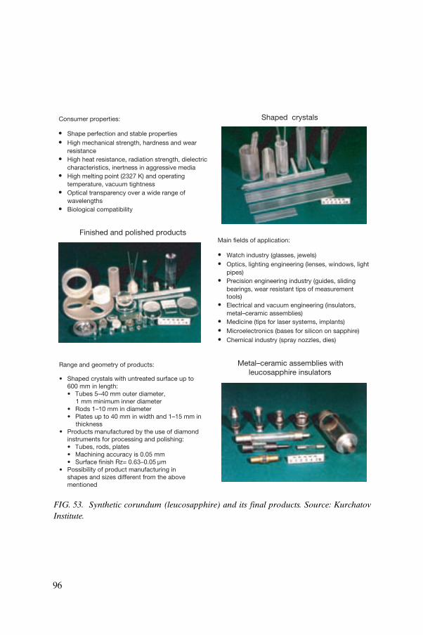
Consumer properties:
• Shape perfection and stable properties• High mechanical strength, hardness and wear
resistance• High heat resistance, radiation strength, dielectric
characteristics, inertness in aggressive media• High melting point (2327 K) and operating
temperature, vacuum tightness• Optical transparency over a wide range of
wavelengths• Biological compatibility
Main fields of application:
• Watch industry (glasses, jewels)• Optics, lighting engineering (lenses, windows, light
pipes)• Precision engineering industry (guides, sliding
bearings, wear resistant tips of measurementtools)
• Electrical and vacuum engineering (insulators,metal–ceramic assemblies)
• Medicine (tips for laser systems, implants)• Microelectronics (bases for silicon on sapphire)• Chemical industry (spray nozzles, dies)
Range and geometry of products:
Shaped crystals with untreated surface up to600 mm in length:• Tubes 5–40 mm outer diameter,
1 mm minimum inner diameter• Rods 1–10 mm in diameter• Plates up to 40 mm in width and 1–15 mm in
thicknessProducts manufactured by the use of diamondinstruments for processing and polishing:• Tubes, rods, plates• Machining accuracy is 0.05 mm• Surface finish Rz= 0.63–0.05 µmPossibility of product manufacturing inshapes and sizes different from the abovementioned
Finished and polished products
Metal–ceramic assemblies withleucosapphire insulators
Shaped crystals
•
•
•
FIG. 53. Synthetic corundum (leucosapphire) and its final products. Source: Kurchatov Institute.
96

• Emitter and collector materials for thermionic converters• Fuel element claddings for nuclear reactors• X ray tube anodes• High power laser reflection mirrors• Targets for sputtering• Electron tube components• Gas turbine components• Crucibles and boats for sintering and melting of materials• Heat pipes
FIG. 54. Single crystals — structural materials of the 21st century. Source: Kurchatov Institute.
97

The refrigerant C1 is a chemically inert, colourless gas which is non-toxic and ozone friendly. It features low global warming potential (0.015) and zero ozone depletion potential. The impact on the environment of the refrigerant C1 in comparison with other refrigerants is shown in Fig. 57.
8.8. PROBLEMS TO BE SOLVED IN SPACE BY THE USE OF NUCLEAR POWER
The cooperative research carried out by the Russian Aviation and Space Agency, MINATOM and others has defined a list of long term space problems, the solution of which will require higher power levels than those currently available.
The most important initiatives to be taken in space with respect to nuclear power in the 21st century are:
FIG. 55. Power cable duct: (1) current leads with expansion pieces, (2) pressure indicator. Source: Kurchatov Institute.
98

FIG. 56. Environmentally benign refrigerant C1. Source: Kurchatov Institute.
99

(a) Development of a new generation of international systems for communi-cation, television broadcasting, navigation, remote sensing, exploration for resources, ecological monitoring and the forecasting of natural geological events on earth;
(b) Production of special materials in space;(c) Establishment of a manned station on the moon, development of a lunar
NPS, commercial exploitation of lunar resources; (d) Launch of manned missions to Mars and to planetary satellites;(e) Transportation to the earth of thermonuclear fuel — the 3He isotope;(f) Removal of radioactive waste that is not in deep underground disposal to
burial places in space and clearing of refuse (space satellites and their fragments) from space;
R143aR125R134aR32R152aC1
R123 R124MP39
R22R141b
HP80
R502R115
R114
R12
R113
R11
0.01 0.1 1 10
0
0.001
0.01
0.1
1
Global warming potential (GWP)(relative to R11)
)P
DO( laitnetop noitelped enoz
O)11
R ot evitaler(
FIG. 57. Impact of refrigerant C1 on the environment in comparison with other refrigerants. Source: Kurchatov Institute.
100

(g) Protection of the earth from potentially dangerous asteroids and the restoration of the earth’s ozone layer, etc.
9. CONCLUSIONS
This publication has been prepared within the framework of the IAEA’s innovative reactor and fuel cycle technology development activities. It attempts to elucidate the role that peaceful, space related nuclear power research and development could play in innovative terrestrial reactor and fuel cycle technology development initiatives. In assessing the status and reviewing the role of nuclear power in the peaceful exploration of space, it also aims to initiate a discussion on the potential benefits of space related nuclear power technology research and development for the research and development of innovative terrestrial nuclear systems.
Active space exploration started at the beginning of the 20th century when amateur and semi-professionals engaged in rocket science, conducting trial and error experiments to leave the ground, if not earth. They made steady but not dramatic progress.
However, just as flight had received government support during World War I, so rocket development received the same support during World War II, and spacecraft development received government backing during the Cold War. The advances in each case were dramatic.
Fortunately, since the Cold War ended, space exploration has matured in a healthier environment. International cooperation is the order of the day, including the building and manning of the earth’s first space station.
On one hand, a large number of nations cooperate in the business of launching meteorological and telecommunications satellites and in putting basic scientific experiments into orbit in order to improve the quality of life and education of their own populations. Launching satellites into earth orbit is now an everyday business. On the other hand, a number of the larger nations, China, Japan, the Russian Federation and the USA are, or want to become, engaged in the exploration of the planets and space. This is an expensive business and one without an immediate financial return. However, the potential rewards in terms of new mineral resources and in an expansion of the human realm are large enough to make the investment worthwhile.
Both China and the Russian Federation have noted that the lunar regolith (soil) could be mined for 3He for use in nuclear fusion power plants on earth. This isotope is very rare on the earth but has been deposited in the lunar
101

soil by the action of the solar wind over billions of years. Use of 3He would perhaps make nuclear fusion conditions much easier to attain, removing one of the major obstacles to obtaining nuclear fusion conditions in plasma containment reactors for power production on earth. Rare earths that can contribute to the world’s technology can be expected to occur on other planets.
It is in regard to the possible mining of minerals on outlying planets and moons, in which manned spacecraft could be involved for long durations and in adverse conditions, that nuclear powered systems come into their own.
Therefore, when planners begin to examine return space travel goals beyond earth orbit, beyond 2005 when the ISS is scheduled to be complete, they are faced with making bigger, more powerful and incredibly more expensive versions of the chemical rockets currently in use. Either that, or they will need to consider a demonstrated technology that was abandoned almost 30 years ago: nuclear rocket propellant engines as well as nuclear powered generators for use on planets such as Mars. Designs already exist for all these enterprises.
Nuclear propulsion is again coming to the fore in space just as a new generation of terrestrial nuclear power plants started to be introduced in 2003.
One system that holds promise is a concept for a bimodal nuclear thermal rocket, a mission design that uses nuclear reactors to produce thrust as well as electricity for a manned mission to Mars. It was developed at the US Glenn Research Center. The detailed mission design would send two cargo vehicles to Mars in 2011, followed by a crew carrier that would leave earth in 2014. Each of the vehicles would be launched in two parts aboard chemical rockets made of modified space shuttle style rocket boosters. The two part vehicles would be assembled in earth orbit before the nuclear reactors are started up to propel the spacecraft to Mars. A block of three small nuclear rockets capable of producing 7000 kg of thrust each would drive each of the vehicles. The reactor cores would provide plenty of energy to get the cargo and crew to and from Mars quickly, to brake into planetary orbit, generate electrical power and even produce artificial gravity during transit.
It is a fact that serious manned missions in space, in particular the first one to Mars, will require nuclear power if humankind is to take the next step beyond the threshold of its own world.
However, the work on building specific space systems that use nuclear power has been halted since 1990. Space nuclear power activities were transferred backwards from the development level to the research level thus postponing, for the time being, further work on the building of space reactors.
Space technologies are not used merely because humankind is not ready to use them. In the future, space nuclear power will be needed in various high
102

power demand space missions. For example, the flow of data will grow enormously and spacecraft with sufficiently powerful nuclear systems placed in geostationary orbits will be needed to manage this flow of data; the previously used low power RTGs will not do the job.
High end technologies can also be developed in space. For a variety of reasons, certain processes cannot take place on earth. For example, superpure materials, single crystals and inorganic materials that are needed on earth can only be produced in space. In the long term, it may be possible to transmit power to the earth from space by microwave or laser energy to provide inacces-sible areas with electrical power.
Furthermore, the exploration of outer space will continue as humans venture to Mars and beyond. All this requires significant energy and, thus, necessitates the use of NTPs.
It is necessary to start preparing for these prospects now, for it will take several decades to master many of the necessary technologies and techniques on a wide scale. Reference points should be established correctly and the development of key technologies systematically pursued. These key technol-ogies include energy conversion systems for high power levels, heat rejection systems, fabrication of required materials, etc. Many of them can be used in other areas as well, for example, thermionic converters are applicable to solar energy conversion, including solar bimodal systems.
Development of space NPSs is a complex and expensive activity. To do it successfully, it is necessary to establish international cooperation and collabo-ration in this field. This cooperation can be built around the extensive nuclear technology base that has been created in the Russian Federation and the USA in past years.
The scale of growth of space activities, the complication of tasks to be fulfilled by space techniques, and the increasing requirements for power and propulsion lead to the use of nuclear power. Nuclear power will dominate in providing propulsion and power units for future near earth and interplanetary missions. There are no alternatives for missions to outer space or for landing on planetary surfaces.
An efficient way to facilitate space nuclear power development is to organize international programmes that use the best achievements of the participating countries. Possible international cooperative efforts include a nuclear powered probe for missions to the outer planets of the solar system and a manned mission to Mars.
However, beyond the purely scientific rationale for space exploration it is clear that exploration facilitated by nuclear power could pay great dividends in many areas of terrestrial development. These areas include civil nuclear power, direct conversion systems, medicine, laser equipment and electronic devices,
103

optics, time keeping processes, refrigeration equipment and materials technology. Many of these benefits to the quality of life on earth arise from our exploration in space no matter what energy option is selected. Many come from simply orbiting the earth on extended missions using chemical propulsion and solar power. However, some benefits only arise from space exploration beyond the capabilities of solar power, when power, heat and propulsion requirements mandate the nuclear option. As a result, research and development into nuclear power and generating systems in space is at the forefront of innovation.
The timing of the research and development work is also of importance. A mission to Mars that would require nuclear power is on the same timescale as the construction of a new innovative nuclear power plant. Both are targeted about 30 years hence. This conjunction provides for real cross-fertilization possibilities from the space related research and development work.
Space related nuclear power research and development can be of the greatest benefit to research and development efforts in the area of innovative reactors and fuel cycles, currently ongoing and being fostered internationally by various initiatives. Ideas that stimulate a new vision for terrestrial power systems, both large and small, include new ion plasma propulsion systems, new high efficiency gas cooled reactors, a re-examination of high efficiency generation cycles perhaps involving fluids other than steam and the use of heat pipes for compact reactors for very specialized and localized usage. Cross-fertilization between space nuclear power research and development on the one hand and innovative reactor and fuel cycle technology research and development for terrestrial applications on the other is possible and should be encouraged.
10. LOOKING AHEAD
It is well known that vast benefits could accrue to humankind once space stations, interplanetary transportation and planetary residence become commonplace. However, these potential benefits are as yet ill defined.
Much research is being pursued in both the Russian Federation and the USA towards the development of new nuclear powered propulsive units and nuclear powered electrical generators for onboard use and for planetary surface activities. China and Japan are also engaged in research with the same long term aims. However, all this research does not indicate much more than speculation about the material benefits of space exploration.
104

In Section 8.7, nine areas of technology are listed which could benefit from advances in the work of preparing for and undertaking space exploration. Some benefits will arise from the preparation through the innovations that are required in information transmission, the use of materials in extreme conditions, in precision and miniaturization technologies, and in human existence in space. Other benefits will only arise following the exploitation of the resources of the planets perhaps fifty years from now.
The benefits to earth can be divided into the following broad categories:
(a) The development of materials capable of withstanding very severe environments;
(b) The development of small nuclear power generators in remote locations (and perhaps in harsh environments) under remote control;
(c) The development of direct energy conversion systems;(d) Knowledge of the medical effects of zero gravity and long term
confinement on humans;(e) Precision technology (optics, lasers, time keeping, electronic devices,
etc.);(f) The use of rare earths and other materials known to exist elsewhere in the
solar system.
Given these potential benefits to earth, the international community is encouraged to pursue multidisciplinary research and development in areas such as space, nuclear engineering, energy cycles and material sciences. Within this context, the IAEA has a role to play in attaining a better understanding of the benefits to be gained, in promoting their use and in facilitating their incor-poration into planning for terrestrial applications.
105

.

App
endi
x I
EV
AL
UA
TIO
N O
F M
AR
S M
ISSI
ON
S
MA
RS
MIS
SIO
N C
OM
PAR
ISO
N
107

App
endi
x I
I
SPA
CE
CR
AF
T L
AU
NC
HE
S IN
VO
LVIN
G R
AD
IOIS
OT
OP
E S
YST
EM
S
Pow
erso
urce
Num
ber
of
RT
Gs
Spac
ecra
ftM
issi
onty
peL
aunc
hda
teSt
atus
SNA
P-3
(U
S)1
Tran
sit 4
AN
avig
atio
nal
29 J
un. 1
961
Cur
rent
ly in
orb
it.
SNA
P-3
(U
S)1
Tran
sit 4
BN
avig
atio
nal
15 N
ov. 1
961
Cur
rent
ly in
orb
it.
SNA
P-9
A (
US)
1Tr
ansi
t 5B
N-1
Nav
igat
iona
l28
Sep
. 196
3C
urre
ntly
in o
rbit
.
SNA
P-9
A (
US)
1Tr
ansi
t 5B
N-2
Nav
igat
iona
l5
Dec
. 196
3C
urre
ntly
in o
rbit
.
SNA
P-9
A (
US)
1Tr
ansi
t 5B
N-3
Nav
igat
iona
l12
Apr
. 196
4M
issi
on a
bort
ed. H
eat s
ourc
e bu
rned
up
on r
e-en
try
as
desi
gned
.
OR
ION
-1 (
S/R
)1
Cos
mos
84
Nav
igat
iona
l3
Sep.
196
5C
urre
ntly
in o
rbit
.
OR
ION
-2 (
S/R
)1
Cos
mos
90
Nav
igat
iona
l18
Sep
. 196
5C
urre
ntly
in o
rbit
.
SNA
P-1
9 (U
S)2
Nim
bus
B-1
Met
eoro
logi
cal
18 M
ay 1
968
Mis
sion
abo
rted
and
hea
t sou
rce
retr
ieve
d.
SNA
P-1
9 (U
S)2
Nim
bus
III
Met
eoro
logi
cal
14 A
pr. 1
969
Cur
rent
ly in
orb
it.
AL
RH
U (
US)
Hea
ter
Apo
llo 1
1L
unar
16 J
ul. 1
969
On
luna
r su
rfac
e.
SNA
P-2
7 (U
S)1
Apo
llo 1
2L
unar
/AL
SEP
14 N
ov. 1
969
On
luna
r su
rfac
e. S
tati
on s
hut
dow
n.
SNA
P-2
7 (U
S)1
Apo
llo 1
3L
unar
/AL
SEP
11 A
pr. 1
970
Mis
sion
abo
rted
. Hea
t sou
rce
jett
ison
ed in
to th
e P
acif
ic O
cean
.
(US
= U
SA, S
/R =
Sov
iet/
Rus
sian
)
108

RH
S fo
r L
unok
hod-
1 (S
/R
)
Hea
ter
Lun
a-17
Lun
ar18
Nov
. 197
0O
n lu
nar
surf
ace.
SNA
P-2
7 (U
S)1
Apo
llo 1
4L
unar
/AL
SEP
31 J
an. 1
971
On
luna
r su
rfac
e. S
tati
on s
hut
dow
n.
SNA
P-2
7 (U
S)1
Apo
llo 1
5L
unar
/AL
SEP
26 J
ul. 1
971
On
luna
r su
rfac
e. S
tati
on s
hut
dow
n.
SNA
P-1
9 (U
S)1
Pio
neer
10
Pla
neta
ry2
Mar
. 197
2Su
cces
sful
ly o
pera
ted
to J
upit
er
and
beyo
nd th
e so
lar
syst
em.
SNA
P-2
7 (U
S)1
Apo
llo 1
6L
unar
/AL
SEP
16 A
pr. 1
972
On
luna
r su
rfac
e. S
tati
on s
hut
dow
n.
Tran
sit-
RT
G U
S)1
Trai
d-01
-1X
Nav
igat
iona
l2
Sep.
197
2C
urre
ntly
in o
rbit
.
SNA
P-2
7 (U
S)1
Apo
llo 1
7L
unar
/AL
SEP
7 D
ec. 1
972
On
luna
r su
rfac
e. S
tati
on s
hut
dow
n.
RH
S fo
r L
unok
hod-
2 (S
/R
)
Hea
ter
Lun
a-21
Lun
ar8
Jan.
197
3O
n lu
nar
surf
ace.
SNA
P-1
9 (U
S)4
Pio
neer
11
Pla
neta
ry5
Apr
. 197
3Su
cces
sful
ly o
pera
ted
to J
upit
er,
Satu
rn a
nd b
eyon
d th
e so
lar
syst
em.
(US
= U
SA, S
/R =
Sov
iet/
Rus
sian
)
SPA
CE
CR
AF
T L
AU
NC
HE
S IN
VO
LVIN
G R
AD
IOIS
OT
OP
E S
YST
EM
S (c
ont.)
Pow
erso
urce
Num
ber
of
RT
Gs
Spac
ecra
ftM
issi
onty
peL
aunc
hda
teSt
atus
109

SNA
P-1
9 (U
S)2
Vik
ing
1M
ars
Lan
der
20 A
ug. 1
975
On
Mar
tian
sur
face
. Lan
der
shut
do
wn.
SNA
P-1
9 (U
S)2
Vik
ing
2M
ars
Lan
der
9 Se
p. 1
975
On
Mar
tian
sur
face
. Lan
der
shut
do
wn.
MH
W-R
TG
(U
S)2
LE
S 8,
LE
S 9
Com
mun
icat
ion
14 M
ar. 1
976
Cur
rent
ly in
orb
it.
MH
W-R
TG
(U
S)3
Voy
ager
2P
lane
tary
20 A
ug. 1
977
Succ
essf
ully
ope
rate
d to
Nep
tune
an
d be
yond
the
sola
r sy
stem
.
MH
W-R
TG
(U
S)3
Voy
ager
1P
lane
tary
5 Se
p. 1
977
Succ
essf
ully
ope
rate
d to
Nep
tune
an
d be
yond
the
sola
r sy
stem
.
GP
HS-
RT
G (
US)
2G
alile
oP
lane
tary
18 O
ct. 1
989
Succ
essf
ully
ope
rate
d, o
rbit
ing
Jupi
ter.
GP
HS-
RT
G (
US)
1U
lyss
esP
lane
tary
6 O
ct. 1
990
Succ
essf
ully
ope
rate
d to
the
sun’
s po
lar
regi
ons,
mis
sion
con
tinu
ing.
LWR
HU
(U
S)H
eate
rM
ars
Pat
hfin
der
Mar
s L
ande
r4
Dec
. 199
6Su
cces
sful
ly o
pera
ted
on M
ars.
GP
HS-
RT
G (
US)
3C
assi
niP
lane
tary
15 O
ct. 1
997
Succ
essf
ully
ope
rate
d, e
n ro
ute
to
Satu
rn.
(US
= U
SA, S
/R =
Sov
iet/
Rus
sian
)
SPA
CE
CR
AF
T L
AU
NC
HE
S IN
VO
LVIN
G R
AD
IOIS
OT
OP
E S
YST
EM
S (c
ont.)
Pow
erso
urce
Num
ber
of
RT
Gs
Spac
ecra
ftM
issi
onty
peL
aunc
hda
teSt
atus
110

App
endi
x II
I
SPA
CE
AC
HIE
VE
ME
NT
S
Pro
gram
me
Dat
eA
chie
vem
ent
Nuc
lear
pow
er r
equi
rem
ent
Sput
nik
4 O
ct. 1
957
Firs
t art
ific
ial s
atel
lite.
Vos
tok
12 A
pr. 1
961
Firs
t man
ned
flig
ht in
out
er s
pace
(Y
.A.
Gag
arin
).
Vos
tok
16–1
9 Ju
n. 1
963
Firs
t wom
an c
osm
onau
t (V
.V. T
eres
hkov
a).
Vos
khod
18 M
ar. 1
965
Firs
t wal
k in
spa
ce (
A.A
. Leo
nov)
.
Lun
a 16
, 20,
24
1958
–197
6L
ande
d an
d re
turn
ed fr
om lu
nar
surf
ace
wit
h sa
mpl
e m
ater
ials
.
Ven
era
and
Veg
a19
65–1
984
Ven
us e
xplo
rati
on: V
ener
a 3
(196
5) r
each
ed th
e su
rfac
e; V
ener
a 8
land
ed (
1972
); V
ener
a 15
/16
orbi
ted
(198
1–19
83)
and
Veg
a 1/
2 dr
oppe
d ca
psul
es.
Apo
llo 1
2, 1
4, 1
5,
16, 1
719
69–1
972
Firs
t lun
ar la
ndin
g (N
.E. A
rmst
rong
and
E.E
. Ald
rin)
and
furt
her
expl
orat
ion
land
ings
.Fi
ve lu
nar
surf
ace
expe
rim
ent
Pac
kage
s (a
ll SN
AP
-27)
des
igne
d fo
r a
year
of l
unar
day
s an
d ni
ghts
wer
e us
ed.
Mar
s 5
1973
Succ
essf
ul m
issi
on to
inve
stig
ate
Mar
s.
Cos
mos
(R
OR
SAT
)19
70–1
988
BU
K N
PS
oper
atio
nal o
n sp
ace
vehi
cles
of t
he
Cos
mos
ser
ies.
32 B
UK
NP
Ss w
ith
elec
tric
al p
ower
of
abou
t 3 k
W.
111

Pio
neer
10
and
1110
: 197
2–19
97
11: 1
973–
1995
10: S
urvi
val o
f the
ast
eroi
d be
lt e
n ro
ute
to
Jupi
ter
and
pass
age
outs
ide
the
sola
r sy
stem
.11
: Exp
lora
tion
of S
atur
n an
d it
s ri
ngs
befo
re le
avin
g th
e so
lar
syst
em.
The
se w
ere
mis
sion
s of
long
dur
atio
n an
d ow
ing
to d
ista
nce
from
the
sun
sola
r po
wer
was
not
feas
ible
for
runn
ing
expe
rim
ents
. E
ach
spac
ecra
ft
had
four
SN
AP
-19
RT
Gs
prov
idin
g
165
W a
t lau
nch.
Vik
ing
1 an
d 2
1975
Pla
ced
two
land
ers
on M
ars.
Eac
h la
nder
had
two
SNA
P-1
9 R
TG
s to
mai
ntai
n se
nsit
ive
equi
pmen
t.
Voy
ager
1 a
nd 2
1977
–198
2E
xplo
rati
on o
f Jup
iter
, Sat
urn,
Ura
nus
and
Nep
tune
.T
hese
spa
cecr
afts
eac
h ha
d a
new
m
ulti
hund
red
wat
t RT
G fo
r a
sign
ific
ant i
ncre
ase
in o
pera
tion
al li
fe
of fo
ur y
ears
.
Mir
1986
–200
1Fi
rst m
odul
ar o
rbit
al s
pace
sta
tion
.
Cos
mos
(P
LA
SMA
-A)
1987
–198
8T
OPA
Z N
PS
oper
atio
n on
boar
d sp
ace
vehi
cles
of
the
Cos
mos
ser
ies.
2 T
OPA
Z N
PSs
wit
h an
ele
ctri
cal
pow
er o
f abo
ut 6
kW
.
Gal
ileo
1989
New
gen
eral
pur
pose
hea
t sou
rce
for
muc
h la
rger
pow
er re
quir
emen
ts (3
00 W
fo
r si
x ye
ars)
.
Uly
sses
1990
Join
t pro
gram
me
wit
h E
SA. O
rbit
ing
the
sun
to
inve
stig
ate
suns
pots
, sol
ar fl
ares
, X r
ays
and
radi
o no
ise,
hel
iosp
here
and
sol
ar w
ind.
Rel
ied
on u
sing
Jup
iter
’s g
ravi
ty to
re
ach
sola
r or
bit a
nd th
eref
ore
sola
r pa
nels
wer
e no
t pos
sibl
e (J
ovia
n su
nlig
ht is
4%
of t
hat n
ear
eart
h).
SPA
CE
AC
HIE
VE
ME
NT
S (c
ont.)
Pro
gram
me
Dat
eA
chie
vem
ent
Nuc
lear
pow
er r
equi
rem
ent
112
Mar
s P
athf
inde
r19
97L
ande
d a
robo
tic
rove
r, S
ojou
rner
, on
Mar
s.T
he r
over
use
d lig
htw
eigh
t RH
Us
to
mai
ntai
n el
ectr
onic
com
pone
nts
at
oper
atin
g te
mpe
ratu
res
duri
ng th
e M
arti
an n
ight
.
Cas
sini
1997
to a
rriv
e at
Sa
turn
in 2
004
Inte
rnat
iona
l pro
ject
to s
tudy
Sat
urn
and
its
ring
sfo
r fo
ur y
ears
and
to p
lace
the
Huy
gens
pro
be o
n T
itan
.
Req
uire
s 3
GP
HSs
and
117
ligh
twei
ght
RH
Us.
Eur
opa
2003
to a
rriv
e at
E
urop
a in
200
7To
det
erm
ine
if th
ere
is li
quid
oce
an b
elow
the
ice
on J
upit
er’s
moo
n an
d to
det
erm
ine
its
char
acte
rist
ics.
An
adva
nced
rad
iois
otop
e po
wer
sy
stem
cou
ld p
rovi
de 2
10 W
six
yea
rs
afte
r la
unch
.
Plu
to/K
uipe
r E
xpre
ss20
04 to
arr
ive
at P
luto
in 2
012
To e
xplo
re P
luto
and
its
moo
n, C
haro
n.P
lann
ing
is fo
r ra
dioi
soto
pe p
ower
sy
stem
pro
vidi
ng 1
85 W
of e
lect
rici
ty
14 y
ears
aft
er la
unch
.
Sola
r pr
obe
2007
to a
rriv
e at
the
sun
in 2
010
To m
easu
re th
e so
lar
win
d, th
e he
atin
g of
the
sola
r co
rona
, to
dete
ct s
olar
wav
es a
nd
turb
ulen
ce, a
nd to
vie
w th
e po
les.
Not
yet
pla
nned
.
SPA
CE
AC
HIE
VE
ME
NT
S (c
ont.)
Pro
gram
me
Dat
eA
chie
vem
ent
Nuc
lear
pow
er r
equi
rem
ent
113

App
endi
x IV
CA
SSIN
I SP
AC
EC
RA
FT
niag-hgih m-4
annetna niag -wol
)2 fo 1( annetna
ya b r ada r
dna sd lei fel cit rap
tellap
na tit sne gyuh eborp
k nat tnal lepo rp
)4( r etsul c re tsurht
ne N 5 44g
en i(2
)
4-m
hig
h-ga
inan
tenn
alo
w-g
ain
ante
nna
(1 o
f 2)
rada
r ba
y
field
s an
dpa
rtic
le p
alle
t
Huy
gens
Tita
npr
obe
prop
ella
nt ta
nk
thru
ster
clu
ster
(4)
445
N e
ngin
e (2
)re
actio
nw
heel
(4)
radi
oiso
tope
ther
moe
lect
ricge
nera
tors
(3)
rem
ote
sens
ing
palle
t
11-m
mag
neto
met
erbo
om
114

Appendix V
AMTEC
Na liquid from
condenser becomes a
vapour at the evaporator
and flows into BASE tube
condenser end
evaporator
end
electron at
BASE = Beta Alumina Solid Electrolyte
Electron Flow
Na vapour travels
to cell condenser
sodium ion picks up
an electron at
electrode–BASE interface Emits electron at
electrode–BASE
interface and Na ion
enter BASE
115

App
endi
x V
I
PR
OP
UL
SIO
N P
ER
FO
RM
AN
CE
(S
ourc
e: L
os A
lam
os N
atio
nal L
abor
ator
y)
EN
ER
GY
SO
UR
CE
PH
YS
ICA
LS
YS
TEM
THE
OR
ETI
CA
LS
PE
CIF
ICIM
PU
LSE
MA
SS
RAT
IO*
EA
RTH
ES
CA
PE
CH
EM
ICA
LR
EA
CTI
ON
HY
DR
OG
EN
HE
ATE
D B
YFI
SS
ION
RE
AC
TOR
DIR
EC
TFI
SS
ION
THE
RM
ON
UC
LEA
RFU
SIO
N
AN
NIH
ILAT
ION
OF
MAT
TER
EN
ER
GY
EN
ER
GY
EN
ER
GY
*RAT
IO O
F TA
KE
-OFF
TO
FIN
AL
MA
SS
15 3.2
1.5
1.2
1.00
1
1.00
03
1.00
003
4300
9600
25 5
00
66 0
00
1.3
× 1
07
3.6
× 1
07
3 ×
108
LIQ
UID
HY
DR
OG
EN
LIQ
UID
OX
YG
EN
OR
FLU
OR
INE
LIQ
UID
HY
DR
OG
EN
U23
5
H+
+ e
– GA
SE
OU
S C
OR
E
H2
SO
LID
CO
RE
H M
OLT
EN
CO
RE
5000
K
2700
K
20 0
00 K
4H
MA
SS
FIS
SIO
N F
RA
GM
EN
TS +
HE
LIU
M +
E =
mc2
116

Appendix VII
THE ROVER PROGRAMME
1955 Following several years of nuclear rocket studies, nuclear rocket programme initiated as Project Rover at Los Alamos National Laboratory. Concept to be pursued was solid core. H2 cooled, reactor expanding gas through a rocket nozzle.
Jul. 1959 First reactor test, Kiwi-A, performed at 70 MW for 5 min.
Oct. 1960 Proof-of-principle tests (Kiwi-A series of three reactors completed).
Jul. 1961 Industrial contractors (Aerojet General for rocket engine and Westinghouse Electric Corporation for reactor) selected to perform rocket development phase. Reactor in-flight test programme initiated.
1963 Reactor in-flight test programme cancelled.
1961–1964 Kiwi-B series of 1000 MW reactor tests included five reactors plus several cold flow unfueled reactors to resolve vibration problems and demonstrate design power.
May–Sep. 1964
First full power test, Kiwi-B4D, at design power with no indications of core vibrations. Also demonstrated restart capability.
Sep. 1964 NRX-A2, first tests of the NERVA (NERVA = nuclear engine for rocket vehicle application) reactor, reached full power of 1100 MW for about 5 min.
Jan. 1965 Kiwi-B type reactor deliberately placed on fast transient to destroy itself as part of safety programme.
Jun. 1965 The prototype of a new class of reactors, Phoebus-1A, was run at full power for 10.5 min.
Mar. 1966 The NRX/EST, first rocket engine ‘bread board’ power plant, operated at full power (1100 MW) for 13.5 min.
Dec. 1967 The fifth fuelled NRX reactor in the NERVA series exceeded the design goal of 60 min at 1100 MW.
Jun. 1968 The Phoebus-2A — the most powerful nuclear rocket reactor ever built — ran for 12 min above 4000 MW.
Dec. 1968 Set records in power density and temperature, operating at 503 MW for 40 min at 2550 K and core power density of 2340 MW/m3.
Mar. 1969 The first down firing prototype nuclear rocket engine, XE-prime, was successfully operated at 1100 MW.
1969 Saturn V production suspended (prime launch vehicle for NERVA).
Jun. 1972 In the 44 MW Nuclear Furance (NF-1), fuel was demonstrated at peak power densities of approximately 4500 MW/m3 and temperatures up to 2500 K for 109 min.
Jan. 1973 Nuclear rocket programme terminated. Judged a technical success but changing national priorities resulted in cancellation decision.
117

Appendix VIII
COMPARISON OF REACTOR SIZESComparison of reactors tested in the Rover Programme
(Source: NASA)
118

Appendix IX
SOVIET NUCLEAR POWER SYSTEMS IN SPACE
No. Space vehicle (NPS) Launch date Time operated(d)
1. Cosmos-367 (BUK) 3 Oct. 1970 For one orbit
2. Cosmos-402 (BUK) 1 Apr. 1971 For two orbits
3. Cosmos-469 (BUK) 25 Dec. 1971 9
4. Cosmos-516 (BUK) 21 Aug. 1972 32
5. Cosmos-626 (BUK) 27 Dec. 1973 45
6. Cosmos-651 (BUK) 15 May 1974 71
7. Cosmos-654 (BUK) 17 May 1974 74
8. Cosmos-723 (BUK) 2 Apr. 1975 43
9. Cosmos-724 (BUK) 7 Apr. 1975 65
10. Cosmos-785 (BUK) 12 Dec. 1975 For three orbits
11. Cosmos-860 (BUK) 17 Oct. 1976 24
12. Cosmos-861 (BUK) 21 Oct. 1976 60
13. Cosmos-952 (BUK) 16 Sep. 1977 21
14. Cosmos-954 (BUK) 18 Sep. 1977 43
15. Cosmos-1176 (BUK) 29 Apr. 1980 134
16. Cosmos-1249 (BUK) 5 Mar. 1981 105
17. Cosmos-1266 (BUK) 21 Apr. 1981 8
18. Cosmos-1299 (BUK) 24 Aug 1981 12
19. Cosmos-1365 (BUK) 14 May 1982 135
20. Cosmos-1372 (BUK) 1 Jun. 1982 70
21. Cosmos-1402 (BUK) 30 Aug 1982 120
22. Cosmos-1412 (BUK) 2 Oct. 1982 39
23. Cosmos-1579 (BUK) 29 Jun. 1984 90
24. Cosmos-1607 (BUK) 31 Oct. 1984 93
25. Cosmos-1670 (BUK) 1 Aug. 1985 83
26. Cosmos-1677 (BUK) 23 Aug. 1985 60
27. Cosmos-1736 (BUK) 21 Mar. 1986 92
28. Cosmos-1771 (BUK) 20 Aug. 1986 56
29. Cosmos-1818 (TOPAZ) 2 Feb. 1987 142
30. Cosmos-1860 (BUK) 18 Jun. 1987 40
119

SOVIET NUCLEAR POWER SYSTEMS IN SPACE (cont.)
31. Cosmos-1867 (TOPAZ) 10 Jul. 1987 342
32. Cosmos-1900 (BUK) 12 Dec. 1987 124
33. Cosmos-1932 (BUK) 14 Mar. 1988 66
34. Cosmos-1933 (BUK) 15 Mar. 1988 60
No. Space vehicle (NPS) Launch date Time operated(d)
120

Appendix X
SPACE EXPLORATION AGENCIES AND CONTRACTORS
X.1. RUSSIAN FEDERATION
Russian space nuclear research and design organizations:
— Ministry for Atomic Energy (MINATOM) is the controlling Government agency.
— Federal State Unitary Enterprise Krasnaya Zvezda (Red Star) (Moscow). Leading organization for the design of BUK and TOPAZ NPSs and the design of advanced NPSs currently being developed.
— State Scientific Center of the Russian Federation — Institute for Physics and Power Engineering (Obninsk). Scientific project manager of BUK and TOPAZ NPSs and IRGIT NPU reactor.
— Russian Research Center — Kurchatov Institute (Moscow). Scientific project manager of Romashka and Yenisey NPSs, and the IGR and IVG-1 research reactors.
— Scientific and Industrial Association Lutch (Podolsk). Leading organi-zation for the production of reactor cores and their elements for the Romashka and Yenisey NPSs, the IRGIT NPU, the IVG-1 research reactor and a number of advanced NPSs and NPPS currently being developed .
— Research and Design Institute of Power Engineering (NIKIET) (Moscow). Leading organization for the design of the IGR and IVG-1 research reactors.
— Central Design Bureau of Machine Building (St. Petersburg). Leading organization for the design of the Yenisey NPS.
— Chemical Automation Design Bureau (Voronezh). Leading organization for the design of the IRGIT NPU.
— Keldysh Research Center (Moscow). Scientific supervisor of work on space power engineering in the Russian Aerospace Agency.
— Energia Rocket and Space Corporation (Korolev). Leading organization for the design of space vehicles for varied applications, including the advanced space vehicles using NPSs. Originator of the NPS based on niobium–lithium technology.
121

X.2. USA
Space exploration work is performed at numerous government agencies, national laboratories and commercial enterprises. The following represents a sample listing of agencies and contractors.
The US Department of Energy’s participation is managed through the Defense Programs Office, with support from the Nuclear Energy Office. Laboratories actively involved include:
— Argonne National Laboratory – West (Argonne, IL). Since 2002 has had custody of the US Department of Energy’s space radioistope power system programme.
— Brookhaven National Laboratory (Upton, NY). Involved in research of reactor materials and component testing, thermal–hydraulic and neutronic analyses, reactor design studies and fuel development activities.
— Idaho National Engineering Laboratory (Idaho Falls, ID). Involved in test facility and mission application conceptual design activities.
— Los Alamos National Laboratory (Los Alamos, NM). — Nevada Test Site (Las Vegas, NV). Involved in test facility conceptual
design activities. — Oak Ridge National Laboratory (Oak Ridge, TN). Involved in the
production of RTGs.— Sandia National Laboratory (Alberquerque, NM). Involved in nuclear
safety, nuclear instrumentation and operation, reactor control systems, nuclear testing, and test facility development and conceptual design activities.
— Savannah River National Laboratory (Aiken, SC). Assisted in the production of RTGs.
— NASA and its facilities are:Ames Research Center;Dryden Flight Research Center;Goddard Institute for Space Studies;Goddard Space Flight Center;Jet Propulsion Laboratory;Johnson Space Center;Kennedy Space Center;Langley Research Center;Lewis Research Center; Marshall Space Flight Center; Stennis Space Center;Wallops Flight Facility.
122

— Air Force Phillips Laboratory (Kirtland Air Force Base, NM). Primary responsibility for the Space Nuclear Thermal Propulsion Program.
— Boeing Corporation. Developing reactor based electrical power for deep space exploration along with its team partners:
Jet Propulsion Laboratory;Glenn Research Center;Honeywell;Swales Aerospace;Auburn University;Texas A&M University.
— Dames & Moore. Provides special services.— Fluor-Daniel Inc. (Irvine, CA). Conducted effluent treatment system
engineering analyses.— Raytheon Services Nevada (Las Vegas, NV). Provides facility and coolant
supply system engineering and facility construction management.— Reynolds Electrical and Engineering Company (Las Vegas, NV).
Supports facility construction activities.— Xerad (Santa Monica, CA). Provides programme support and
independent review services.— Air Force Western Space and Missile Center (Vandenberg Air Force
Base, CA). Provides flight test planning support.— Air Force Arnold Engineering Development Center (Tullahoma, TN).
May provide hydrogen flow engine test support.— Space & Electronics Division, Grumman Corporation (Bethpage, NY).
Operates as a system integrating contractor and provides vehicle design and fabrication and overall programme management services. Grumman’s Calverton Facility at Long Island may be used for hydrogen testing.
— Airesearch Los Angeles Division, Allied Signal Corporation (Torrance, CA). Has been responsible for turbine wheel testing.
— Garrett Fluid Systems Division, Allied Signal Corporation (Tempe and San Tan, AZ). Involved in design and fabrication of fluid management and energy conversion components, including engine turbopump and propellant flow control development, as well as attitude control systems.
— General Dynamics (San Diego, CA). Has conducted launch vehicle and other vehicle integration studies.
— Hercules (Magna, UT). Involved in advanced composite structures for engine lower structure, rocket nozzles and propellant tanks.
— L-Systems is involved in system engineering services.— United Nuclear Corporation (Norwich and Uncasville, CN). Has been
involved in nuclear element canister development, manufacturing and
123

test support. This company is phasing out this line of work, which is being consolidated at Babcock & Wilcox.
— Babcock & Wilcox Nuclear Power Division (Lynchburg, VA). Involved in detailed design of reactor subsystems and fabrication and assembly of reactor technology, including fuel particles.
— Aerojet Division of Gencorp (Sacramento, CA). Subcontractor providing engine technology support, as well as element component design and fabrication, alternate fuel element materials development and test facility design support.
124

Appendix XI
INTERNET REFERENCES
This is a partial listing of web sites which provide information on space exploration and the use of nuclear power in that endeavour. However, most of these URLs have links to other information pages (see Table 10).
For example, http://www.astronautix.com/chrono/index.htm provides a chronology of every significant event from 1910 to 2002 which affected space flight, including every international rocket and spacecraft launch, as well as political, social and technical events. A typical entry then leads to other information pages. A recent entry reads:
“2002 Mar 1 — 01:08 GMT. Launch Site: Kourou. Launch Complex: ELA3. Launch Vehicle: Ariane 5. LV Configuration: Flight V145 / Ariane 511.Envisat Nation: Europe. Mass: 7,991 kg. Class: Earth. Type: Radarsat. Spacecraft: Envisat. Perigee: 766 km. Apogee: 784 km. Inclination: 98.5 deg. COSPAR.”
This launch was the first Ariane 5 to use the 17 m Long Fairing and the first to launch north from Kourou. The booster placed ESA’s Envisat polar platform in orbit. The flight profile was quite different from earlier Ariane 5 GTO launches where the EPC core stage usually reached a marginal orbit. In this case EPC separation occurred at an altitude of 350 km 10 min after launch. The stage was on a –2610 × 651 km × 93.8o orbit, reaching apogee around 0125 UTC and re-entering north of Ellesmere Island at about 0136 UTC. The EPS final stage with Envisat only achieved a positive perigee at 22 min after launch, with a circular 790 km sun synchronous orbit reached 25 min after launch. ESA reported the booster put the satellite to within 20 m of the desired orbital position.
The words ‘Kourou’, ‘Ariane 5’, ‘earth’ and ‘Envisat’ are all hyperlinked to pages which provide further background information. The Kourou link provides the history of the Kourou site, with maps and details of every Ariane launch made from the site since 1970. The Ariane 5 link provides a history of the Ariane 5 rocket, its contractors and its technical specifications, etc. The Envisat link leads to information about European spacecraft, objectives and specifications and, finally, a link to its own home page at http://envisat.esa.int/.The earth link leads to an index.
125

TAB
LE
10.
PA
RT
IAL
LIS
TIN
G O
F W
EB
SIT
ES
WH
ICH
PR
OV
IDE
IN
FO
RM
AT
ION
ON
SPA
CE
EX
PL
OR
AT
ION
Org
aniz
atio
nU
RL
Info
rmat
ion
Enc
yclo
pedi
a A
stro
naut
ica
http
://w
ww
.ast
rona
utix
.com
/chr
ono/
inde
x.ht
mC
hron
olog
ical
inde
x of
eve
ry e
vent
of
inte
rest
in s
pace
from
pol
itics
to
ever
y la
unch
bet
wee
n 19
10 a
nd 2
002
Enc
yclo
pedi
a A
stro
naut
ica
http
://w
ww
.ast
rona
utix
.com
/cra
ft/u
sa.h
tmR
ussi
an–U
S sp
acec
raft
Sven
Gra
hn’s
Spa
ce P
lace
http
://w
ww
.sve
ngra
hn.p
p.se
/H
ome
site
for
Sven
Gra
hn’s
in
vent
ory
of s
pace
info
rmat
ion
Sven
Gra
hn’s
Spa
ce P
lace
http
://w
ww
.sve
ngra
hn.p
p.se
/link
page
.htm
#Spa
ceSp
ace
expl
orat
ion
links
Sven
Gra
hn’s
Spa
ce P
lace
http
://w
ww
.use
rs.w
inea
sy.s
e/sv
engr
ahn/
hist
ind/
hist
ind1
.htm
Spac
e hi
stor
y no
tes
Enc
yclo
pedi
a A
stro
naut
ica
http
://w
ww
.ast
rona
utix
.com
/art
icle
s/so
vsto
ry.h
tmSo
viet
spa
ce h
isto
ry
Enc
yclo
pedi
a A
stro
naut
ica
http
://w
ww
.ast
rona
utix
.com
/cra
ft/s
henz
hou.
htm
Shen
zhou
— th
e de
velo
pmen
t of
Chi
na’s
man
ned
spac
ecra
ft
NA
SAht
tp://
lifto
ff.m
sfc.
nasa
.gov
/Rea
lTim
e/JP
ass/
JPas
s.asp
Rus
sian
spa
cecr
aft
Fede
ratio
n of
Am
eric
an
Sc
ient
ists
http
://w
ww
.fas.o
rg/s
pp/c
ivil/
russ
ia/fe
i.htm
Rus
sian
spa
ce in
dust
ry
Fede
ratio
n of
Am
eric
an
Sc
ient
ists
http
://w
ww
.fas.o
rg/s
pp/c
ivil/
russ
ia/in
dex.
htm
lR
ussi
an s
pace
indu
stry
inde
x
NA
SAht
tp://
lifto
ff.m
sfc.
nasa
.gov
/rsa
/rsa
.htm
lR
ussi
an S
pace
Age
ncy
Indi
an S
pace
Res
earc
h
O
rgan
izat
ion
http
://w
ww
.isro
.org
/pro
gram
mes
.htm
Indi
an s
pace
pro
gram
mes
Spac
e D
aily
http
://w
ww
.spa
ceda
ily.c
om/n
ews/
rock
etsc
ienc
e-02
za.h
tml
“Pow
erin
g up
in d
eep
spac
e”
(art
icle
)
126

NA
SAht
tp://
pow
erw
eb.g
rc.n
asa.
gov/
Pow
er a
nd o
nboa
rd p
ropu
lsio
n te
chno
logy
Enc
yclo
pedi
a A
stro
naut
ica
http
://w
ww
.ast
rona
utix
.com
/cra
ft/p
lazm
aa.h
tmP
lasm
a-A
spa
cecr
aft
Fede
ratio
n of
Am
eric
an
Sc
ient
ists
http
://w
ww
.fas.o
rg/n
uke/
spac
e/in
dex.
htm
lN
ucle
ar th
erm
al p
ropu
lsio
n
Nat
iona
l Spa
ce D
evel
opm
ent
A
genc
y of
Japa
n (N
ASD
A)
http
://je
m.tk
sc.n
asda
.go.
jp/in
dex_
e.ht
ml
Japa
nese
spa
ce p
rogr
amm
e
Spac
eht
tp://
ww
w.s
pace
.com
/new
s/na
sa_n
ucle
ar_0
2020
5.ht
ml
“NA
SA to
go
nucl
ear”
(ar
ticle
)
NA
SAht
tp://
ww
w.h
q.na
sa.g
ov/o
ffic
e/pa
o/H
isto
ry/S
P-4
211/
cont
ents
.htm
NA
SA a
nd th
e hi
stor
y of
spa
ce
expl
orat
ion
and
the
futu
re v
isio
n
NA
SAht
tp://
msl
.jpl.n
asa.
gov/
hom
e.ht
ml
Mis
sion
and
spa
cecr
aft l
ibra
ry
Enc
yclo
pedi
a A
stro
naut
ica
http
://w
ww
.ast
rona
utix
.com
/pro
ject
/lonm
arch
.htm
The
Chi
nese
Lon
g M
arch
pro
ject
NA
SAht
tp://
lifto
ff.m
sfc.
nasa
.gov
/L
ift-o
ff to
spa
ce e
xplo
ratio
n
NA
SDA
ht
tp://
ww
w.n
asda
.go.
jp/p
roje
cts/
rock
ets/
inde
x_e.
htm
lJa
pane
se s
pace
pro
gram
me
USC
ht
tp://
ame-
ww
w.u
sc.e
du/b
io/m
ikeg
/ast
rom
ike/
astr
ospa
ce_0
9.ht
mIn
tern
atio
nal s
pace
link
s
Enc
yclo
pedi
a A
stro
naut
ica
http
://w
ww
.ast
rona
utix
.com
/pro
ject
/inte
lsat
.htm
Inte
lSat
Indi
an S
pace
Res
earc
h
O
rgan
izat
ion
http
://w
ww
.isro
.org
/In
dian
spa
ce o
rgan
izat
ion
Hob
bysp
ace
http
://w
ww
.hob
bysp
ace.
com
/Lin
ks/S
pace
Syst
ems.h
tml#
Nuc
lear
PS
Spac
eflig
ht s
yste
ms
Fran
ce -
Scie
nce
http
://w
ww
.fran
ce-s
cien
ce.o
rg/a
sp/le
ttre
.asp
?LN
G=u
s&P
UB
LID
=7Fr
ench
spa
ce p
rogr
amm
es
TAB
LE
10.
PA
RT
IAL
LIS
TIN
G O
F W
EB
SIT
ES
WH
ICH
PR
OV
IDE
INF
OR
MA
TIO
N O
N S
PAC
E E
XP
LO
RA
TIO
N (c
ont.)
Org
aniz
atio
nU
RL
Info
rmat
ion
127

Fede
ratio
n of
Am
eric
an
Sc
ient
ists
http
://w
ww
.fas.o
rg/
Fede
ratio
n of
Am
eric
an S
cien
tists
—
inde
x
NA
SDA
http
://je
m.tk
sc.n
asda
.go.
jp/is
s/do
c13_
01fp
ef_e
.htm
l#fp
ef1
Japa
n’s
Kib
o ex
peri
men
t the
mes
Enc
yclo
pedi
a A
stro
naut
ica
http
://w
ww
.ast
rona
utix
.com
/cra
ft/e
nerb
ase.
htm
Ene
rgia
luna
r ba
se
Sven
Gra
hn’s
Spa
ce P
lace
http
://w
ww
.use
rs.w
inea
sy.s
e/sv
engr
ahn/
hist
ind/
E3/
E3o
rig.
htm
E-3
Pro
ject
— a
n ea
rly
spac
e nu
clea
r cu
riou
sity
Fede
ratio
n of
Am
eric
an
Sc
ient
ists
http
://w
ww
.fas.o
rg/n
uke/
guid
e/ru
ssia
/doc
trin
e/97
0815
.htm
Rus
sian
dec
ree
on th
e la
unch
of a
sp
acec
raft
with
a n
ucle
ar d
evic
e
CN
ES
(Fra
nce)
http
://w
ww
.cne
s.fr/
enje
ux/2
inde
x.ht
mC
NE
S –
Cha
lleng
e of
Spa
ce
Enc
yclo
pedi
a A
stro
naut
ica
http
://w
ww
.ast
rona
utix
.com
/pro
ject
/chi
asta
r.htm
Chi
nast
ar
Enc
yclo
pedi
a A
stro
naut
ica
http
://w
ww
.ast
rona
utix
.com
/art
icle
s/ch
iitie
s.htm
Chi
nese
spa
ce a
ctiv
ities
Enc
yclo
pedi
a A
stro
naut
ica
http
://w
ww
.ast
rona
utix
.com
/cra
ft/c
hirb
ase.
htm
Chi
na’s
luna
r ba
se p
rogr
amm
e
Thi
s is
by
no m
eans
a c
ompr
ehen
sive
list
ing
of w
eb s
ites
for
spac
e ex
plor
atio
n bu
t the
ir u
se le
ads
to n
umer
ous
of o
ther
UR
Ls.
TAB
LE
10.
PA
RT
IAL
LIS
TIN
G O
F W
EB
SIT
ES
WH
ICH
PR
OV
IDE
INF
OR
MA
TIO
N O
N S
PAC
E E
XP
LO
RA
TIO
N (c
ont.)
Org
aniz
atio
nU
RL
Info
rmat
ion
128

ACKNOWLEDGEMENTS
Many of the figures of this publication are taken from Space Nuclear Power prepared by J.A. Angelo, Jr., and D. Buden and published by the Orbit Book Company, Inc., of Malabar, Florida, USA.
Credit for other figures must go to material from the Russian Research Centre, Kurchatov Institute; the State Scientific Center of the Russian Federation, Institute for Physics and Power Engineering; the National Aeronautics and Space Administration; the US Department of Energy; the Jet Propulsion Laboratory; the Marshall Space Flight Center; and to Mark Ward. Credit is also given to FGUP NII NPO Lutch, Russian Federation.
129

.

BIBLIOGRAPHY
Angelo, J.A., Jr., BUDEN, D., Space Nuclear Power, Orbit Book Company, Malabar, FL (1985).
GRAHAM, J., “A Vision for the Second Fifty Years of Nuclear Energy,” Visions and Strategies, International Nuclear Societies Council, 1966.
ZEYHER, A., Cassini launch delayed while protesters mobilize, Nuclear News, November (1997) 47–51.
POSTON, D.I., Nuclear design of the SAFE-400 space fission reactor, Nuclear News, December (2002) 28–35.
POSTON, D.I., Nuclear design of the Homer-15 Mars surface fission reactor, Nuclear News, December (2002) 36–48.
CHANG, D., FRANKLIN, E., The VASIMR, Scientific American, November (2000) 90–97.
WADE, M. (Ed.), Encyclopedia Astronautica, 2002, http://www.astronautix.com/
MILLIONSHIKOV, M.D., GVERDTSITELI, I.G., MERKIN, V.I., PONOMAREV-STEPNOI, N.N., KUKHARKIN, N.E., USOV, V.A., et al., “ROMASHKA high-temperature converter-reactor”, Peaceful Uses of Atomic Energy (Proc. 3rd Int. Conf. Geneva, 1964), United Nations, New York (1965) (in Russian).
GVERDTSITELI, I.G., KUKHARKIN, N.E., PONOMAREV-STEPNOI, N.N., USOV, V.A., “Main results of 15,000-hour tests of the ROMASHKA high-temperature converter-reactor”, paper presented in the 4th US Energy Conversion Conference, Washington, 1969.
NATIONAL AERONAUTICS AND SPACE ADMINISTRATION, Basics of Space Flight: Section II, 2002, http://www.jpl.nasa.gov/basics/bsf11-4.html#propulsion
NATIONAL AERONAUTICS AND SPACE ADMINISTRATION, Spinoff: Fortieth Anniversary Technology Utilization Program, Rep. NP-2002-09-290-HQ, NASA, Washington, DC (2002).
131

GRIAZNOV, G.M., et al., Space NPS thermionic converter-reactors, At. Ehnerg. 66 6 (1989).
BOGUSH, I.P., et al., Main goals and results of flight tests of the NPS under the TOPAZ Program, At. Ehnerg. 70 4 (1990).
NIKITIN, V.P., OGLOBLIN, B.G., LUPPOV, A.N., et al., “Prospects for development of thermionic space NPS on the basis of existing single-cell TFEs”, paper presented at Int. Conf. on Nuclear Power in Space, Obninsk, 1990.
PONOMAREV-STEPNOI, N.N., USOV, V.A., et al., “Space nuclear power system based on thermionic reactor with single-cell TFEs”, paper presented at 10th Symp. on Space Nuclear Power and Propulsion, Albuquerque, 1993.
GRIAZNOV, G.M., ZHABOTINSKY, E.E., ZRODNIKOV, A.V., et al., “Space Nuclear Power Systems with Direct Energy Conversion”, prepared by Red Star State Enterprise for the Encyclopedic Collection on Nuclear Engineering, 1999.
BOOZ, ALLEN, HAMILTON, TOPAZ International Program, Booz, Allen, Hamilton, McLean, VA (1995).
POUPKO, V.Y., History of Work on Nuclear Propulsion Modules for Space and Aircraft, SSC RF-IPPE, Obninsk (2002).
PONOMAREV-STEPNOI, N.N., USOV, V.A., “Conceptual design of the bimodal nuclear power system based on the Romashka type reactor with the thermionic energy conversion system”, Space Nuclear Power and Propulsion (Proc. 12th Int. Symp. Albuquerque, 1995), American Institute of Physics, New York (1995).
PONOMAREV-STEPNOI, N.N., USOV, V.A., et al., “Conceptual design of the bimodal nuclear power and propulsion system based on the TOPAZ-2 reactor with the modernized single-cell TFE”, Space Nuclear Power and Propulsion (Proc. 12th Int. Symp. Albuquerque, 1995), American Institute of Physics, New York (1995).
GOVERNMENT OF THE RUSSIAN FEDERATION, Decree of the Government of the Russian Federation of February 2, 1998, No. 144, On the Concept of Development of Space Power Engineering in Russia, Rossiyskaya Gazette 26 11 February (1998).
132

CONTRIBUTORS TO DRAFTING AND REVIEW
Andreyev, P.V. Federal State Unitary Enterprise Red Star, Russian Federation
Baranov, G.D. Federal State Unitary Enterprise Red Star, Russian Federation
Graham, J. ETCetera Assessments LLP, United States of America
Ionkin, V. Institute for Physics and Power Engineering, Russian Federation
Pavshook, V.A. Kurchatov Institute, Russian Federation
Ponomarev-Stepnoi, N.N. Kurchatov Institute, Russian Federation
Pushtovalov, A.A. Scientific Industrial Enterprise ANPP BIAPOS, Russian Federation
Sinyavskiy, V.V. Energia Rocket and Space Corporation, Russian Federation
Stanculescu, A. International Atomic Energy Agency
Yarugin, V.I. Institute for Physics and Power Engineering, Russian Federation
133

Nuclear power systems have been used to supplyheating and power to satellites and interplanetaryprobes for more than forty years. This book reviewstheir development and aims to emphasize thepotential benefits that research on space nuclearpower technology can have on the development ofinnovative terrestrial nuclear systems.
International Atomic Energy AgencyVienna
ISBN 92–0–107404–2