The rheology and processing of “edge sheared” … · The rheology and processing of “edge...
13
The rheology and processing of “edge sheared” colloidal polymer opals Hon Sum Wong, Malcolm Mackley, a) and Simon Butler Department of Chemical Engineering and Biotechnology, University of Cambridge, Cambridge CB2 3RA, United Kingdom Jeremy Baumberg, David Snoswell, b) Chris Finlayson, c) and Qibin Zhao Cavendish Laboratory, NanoPhotonics Centre, University of Cambridge, Cambridge CB3 OHE, United Kingdom (Received 23 October 2013; final revision received 2 January 2014; published 31 January 2014) Synopsis This paper is concerned with the rheology and processing of solvent-free core shell “polymer opals” that consist of a soft outer shell grafted to hard colloidal polymer core particles. Strong iridescent colors can be produced by shearing the material in a certain way that causes the initially disordered spheres to rearrange into ordered crystalline structures and produce colors by diffraction and interference of multiple light scattering, similar to gemstone opals. The basic linear viscoelastic rheology of a polymer opal sample was determined as a function of temperature, and the material was found to be highly viscoelastic at all tested temperatures. A Cambridge multipass rheometer was specifically modified in order to make controlled mechanical measurements of initially disordered polymer opal tapes that were sandwiched between protective polyethylene terephthalate sheets. Axial extension, simple shear, and a novel “edge shearing” geometry were all evaluated, and multiple successive experiments of the edge shearing test were carried out at different temperatures. The optical development of colloidal ordering, measured as optical opalescence, was quantified by spectroscopy using visible backscattered light. The development of opalescence was found to be sensitive to the geometry of deformation and a number of process variables suggesting a complex interaction of parameters that caused the opalescence. In order to identify aspects of the deformation mechanism of the edge shearing experiment, a separate series of in situ optical experiments were carried out and this helped indicate the extent of simple shear generated with each edge shear deformation. The results show that strong ordering can be induced by successive edge shearing deformation. The results are relevant to polymer opal rheology, processing, and mechanisms relating to ordering within complex viscoelastic fluids. V C 2014 The Society of Rheology.[http://dx.doi.org/10.1122/1.4862920] a) Author to whom correspondence should be addressed; electronic mail: [email protected] b) Current address: Sclumberger Gould Research, Cambridge CB3 0EL, United Kingdom. c) Current address: Institute of Mathematics, Physics and Computer Science (IMPACS), Prifysgol Aberystwyth University, SY23 3BZ Wales, United Kingdom. V C 2014 by The Society of Rheology, Inc. J. Rheol. 58(2), 397-409 March/April (2014) 0148-6055/2014/58(2)/397/13/$30.00 397
Transcript of The rheology and processing of “edge sheared” … · The rheology and processing of “edge...
The rheology and processing of “edge sheared” colloidalpolymer opals
Hon Sum Wong, Malcolm Mackley,a) and Simon Butler
Department of Chemical Engineering and Biotechnology,University of Cambridge, Cambridge CB2 3RA, United Kingdom
Jeremy Baumberg, David Snoswell,b) Chris Finlayson,c) and Qibin Zhao
Cavendish Laboratory, NanoPhotonics Centre,University of Cambridge, Cambridge CB3 OHE, United Kingdom
(Received 23 October 2013; final revision received 2 January 2014;published 31 January 2014)
Synopsis
This paper is concerned with the rheology and processing of solvent-free core shell “polymer
opals” that consist of a soft outer shell grafted to hard colloidal polymer core particles. Strong
iridescent colors can be produced by shearing the material in a certain way that causes the initially
disordered spheres to rearrange into ordered crystalline structures and produce colors by diffraction
and interference of multiple light scattering, similar to gemstone opals. The basic linear
viscoelastic rheology of a polymer opal sample was determined as a function of temperature, and
the material was found to be highly viscoelastic at all tested temperatures. A Cambridge multipass
rheometer was specifically modified in order to make controlled mechanical measurements of
initially disordered polymer opal tapes that were sandwiched between protective polyethylene
terephthalate sheets. Axial extension, simple shear, and a novel “edge shearing” geometry were all
evaluated, and multiple successive experiments of the edge shearing test were carried out at
different temperatures. The optical development of colloidal ordering, measured as optical
opalescence, was quantified by spectroscopy using visible backscattered light. The development of
opalescence was found to be sensitive to the geometry of deformation and a number of process
variables suggesting a complex interaction of parameters that caused the opalescence. In order to
identify aspects of the deformation mechanism of the edge shearing experiment, a separate series
of in situ optical experiments were carried out and this helped indicate the extent of simple shear
generated with each edge shear deformation. The results show that strong ordering can be induced
by successive edge shearing deformation. The results are relevant to polymer opal rheology,
processing, and mechanisms relating to ordering within complex viscoelastic fluids. VC 2014 TheSociety of Rheology. [http://dx.doi.org/10.1122/1.4862920]
a)Author to whom correspondence should be addressed; electronic mail: [email protected])Current address: Sclumberger Gould Research, Cambridge CB3 0EL, United Kingdom.c)Current address: Institute of Mathematics, Physics and Computer Science (IMPACS), Prifysgol Aberystwyth
University, SY23 3BZ Wales, United Kingdom.
VC 2014 by The Society of Rheology, Inc.J. Rheol. 58(2), 397-409 March/April (2014) 0148-6055/2014/58(2)/397/13/$30.00 397
I. INTRODUCTION
Polymer opals are a relatively new and exciting class of materials that have unusual
rheology, processing, and optical properties [see, for example, Pursiainen et al. (2005);
Snoswell et al. (2010); Finlayson and Baumberg (2013)]. Following the development of
monodisperse colloidal polymer particle suspensions in the 1950s [Alfrey et al. (1954)],
it became clear that they could have interesting optical properties if ordered [see, for
example, Hachisu et al. (1973)]. Subsequently, solvent-free polymer particle spheres
have been developed of the type shown schematically in Fig. 1, where polymer chains
are grafted to the outside of the particles in a manner that creates a solvent-free concen-
trated dispersion of monodisperse spheres within a highly viscoelastic matrix [see, for
example, Ruhl et al. (2003); Viel et al. (2007)]. Because the spheres were of a diameter
similar to the wavelength of light there is potential for these solvent-free materials to ex-
hibit interesting photonic optical effects, particularly if the colloidal particles become or-
dered [see, for example, Ruhl et al. (2004); Pursiainen et al. (2007)].
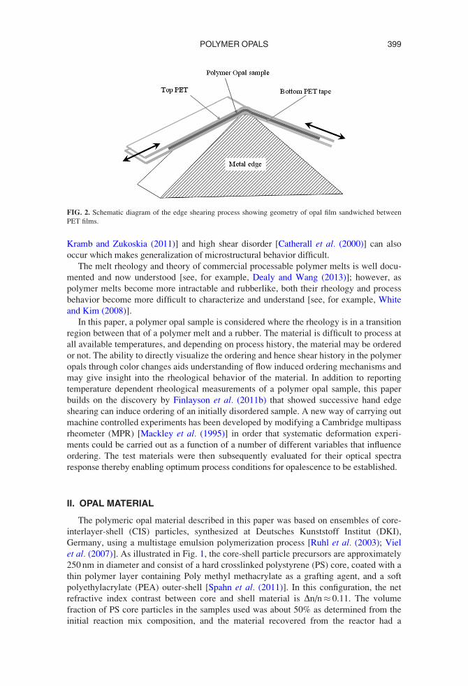
A breakthrough was achieved with the development of an edge-induced rotational
shearing (EIRS) process [Finlayson et al. (2011b)] shown schematically in Fig. 2.
Repeated shearing at elevated temperature around a sharp edge can produce samples with
improved reproducibly and uniformity of bulk-ordering, greatly enhancing both the in-
tensity and chromaticity of the observed structural color. The application of shear order-
ing techniques to these solvent-free systems allow formation of permanent, mechanically
robust composites in the solid-state. An attractive feature of elastomeric polymer opals is
the tunability of their perceived color by the bending or stretch modification of the (111)
plane spacing. As such, these “polymer opals” present opportunities for a step-change
away from the monolithic architectures which are currently relied upon in the field of
photonic structures and are a promising platform for next generation bulk-scale photonics
materials, coatings, fibers, and sensors [Sussman et al. (2009); Finlayson et al. (2011a);
Finlayson and Baumberg (2013)].
The effect of shear on the ordering and rheology of colloidal suspensions in a low vis-
cosity matrix has been reported before, and in general, it has been found that simple shear
is capable of creating order in concentrated colloidal systems [see, for example, Ackerson
and Pusey (1988); Chen et al. (1992); Liu et al. (1993)] with an associated rheological gen-
eral trend of shear thinning [Mewis et al. (1989)]. A number of authors [see, for example,
Ackerson (1990); Haw et al. (1998); Koumakis et al. (2008); McMullan and Wagner
(2009)] have reported the ordering of colloidal suspensions using oscillatory shear and a
review on low viscosity base fluid ordering in steady and oscillatory simple shear is given
by Vermant and Solomon (2005). As the concentration of suspension increases, complica-
tions such as jamming [see, for example, Trappe et al. (2001); Liu and Nagel (2010);
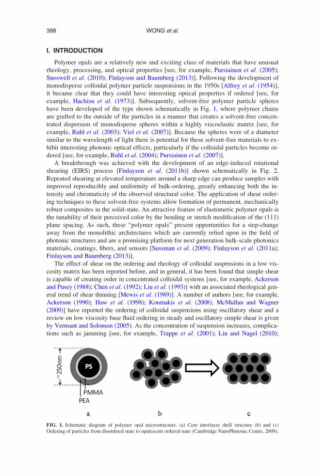
FIG. 1. Schematic diagram of polymer opal microstructure. (a) Core interlayer shell structure (b) and (c)
Ordering of particles from disordered state to opalescent ordered state (Cambridge NanoPhotonic Centre, 2009).
398 WONG et al.
Kramb and Zukoskia (2011)] and high shear disorder [Catherall et al. (2000)] can also
occur which makes generalization of microstructural behavior difficult.
The melt rheology and theory of commercial processable polymer melts is well docu-
mented and now understood [see, for example, Dealy and Wang (2013)]; however, as
polymer melts become more intractable and rubberlike, both their rheology and process
behavior become more difficult to characterize and understand [see, for example, White
and Kim (2008)].
In this paper, a polymer opal sample is considered where the rheology is in a transition
region between that of a polymer melt and a rubber. The material is difficult to process at
all available temperatures, and depending on process history, the material may be ordered
or not. The ability to directly visualize the ordering and hence shear history in the polymer
opals through color changes aids understanding of flow induced ordering mechanisms and
may give insight into the rheological behavior of the material. In addition to reporting
temperature dependent rheological measurements of a polymer opal sample, this paper
builds on the discovery by Finlayson et al. (2011b) that showed successive hand edge
shearing can induce ordering of an initially disordered sample. A new way of carrying out
machine controlled experiments has been developed by modifying a Cambridge multipass
rheometer (MPR) [Mackley et al. (1995)] in order that systematic deformation experi-
ments could be carried out as a function of a number of different variables that influence
ordering. The test materials were then subsequently evaluated for their optical spectra
response thereby enabling optimum process conditions for opalescence to be established.
II. OPAL MATERIAL
The polymeric opal material described in this paper was based on ensembles of core-
interlayer-shell (CIS) particles, synthesized at Deutsches Kunststoff Institut (DKI),
Germany, using a multistage emulsion polymerization process [Ruhl et al. (2003); Viel
et al. (2007)]. As illustrated in Fig. 1, the core-shell particle precursors are approximately
250 nm in diameter and consist of a hard crosslinked polystyrene (PS) core, coated with a
thin polymer layer containing Poly methyl methacrylate as a grafting agent, and a soft
polyethylacrylate (PEA) outer-shell [Spahn et al. (2011)]. In this configuration, the net
refractive index contrast between core and shell material is Dn/n� 0.11. The volume
fraction of PS core particles in the samples used was about 50% as determined from the
initial reaction mix composition, and the material recovered from the reactor had a
FIG. 2. Schematic diagram of the edge shearing process showing geometry of opal film sandwiched between
PET films.
399POLYMER OPALS
rubbery consistency. The material also contained the addition of 0.05 wt. % carbon black
which has been found to enhance optical contrast when opalescence occurs [Pursiainen
et al. (2007)]. A miniextruder (Thermo Scientific, MiniLab) consisting of two counter
rotating metallic screws with adjustable speed in the range 1–150 (rpm), and adjustable
temperature 25–250 �C was used to compound the material. Typical compounding tem-
peratures were �150 �C, and up to 6 g of the opal precursor material was manually fed
into the extruder, where a melt was formed and homogenized under the extreme shear
conditions provided by the screws. The generated overpressure then forced the material
through a narrow-bore stainless steel die, producing rectangular section extrudates of a
few mm thickness. At this stage of processing, the polymer sample had a dull green color
due to limited particle ordering but was not strongly opalescent.
III. VISCOELASTIC RESPONSE
The viscoelasticity of the polymer opal was studied using an Ares rheometer. This
involved applying an oscillatory deformation to the polymer opal sample and measuring
the torque response. Two oscillatory rheometric measurements were made, namely,
a strain sweep test and a frequency sweep test. The strain sweep test was performed at a
fixed angular frequency of 10 rad/s, while the frequency sweep test was performed at a
fixed strain amplitude of 0.01. Between 3 and 5 g of the polymer opal sample was heated
to 150 �C and pressed into a circular aluminum template to form a polymer opal disk
with a diameter of 25 mm and a uniform thickness of 3 mm. The polymer opal disk was
subsequently loaded into the test region of a parallel plate flat disc rheometer. Strain
sweep and frequency sweep tests were then carried out at 25, 100, and 150 �C to measure
the viscoelastic response at the different temperatures. At all the test temperatures, the
shell (PEA) material was above its glass transition temperature (�15 �C), and because
the PS core was crosslinked, the core structure remained intact. These tests captured the
viscoelastic properties of the polymer opal by providing information on the G0 (storage
modulus), G00 (loss modulus), and g* (complex viscosity). Additional steady shearing
experiments were attempted, but the material would not deform uniformly at any temper-
ature for large strains within the parallel plate geometry.
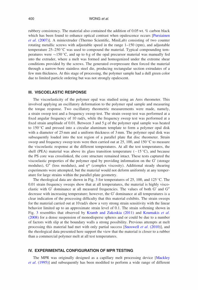
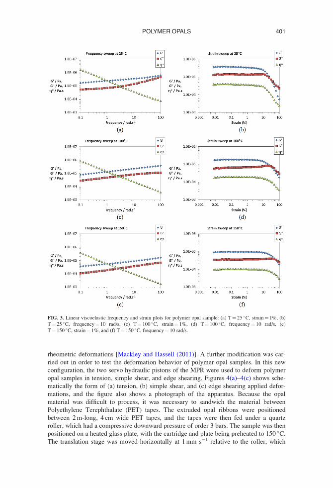
The rheological data are shown in Fig. 3 for temperatures of 25, 100, and 125 �C. The
0.01 strain frequency sweeps show that at all temperatures, the material is highly visco-
elastic with G0 dominance at all measured frequencies. The values of both G0 and G00
decrease with increasing temperature; however, the G0 dominance at all temperatures is a
clear indication of the processing difficulty that this material exhibits. The strain sweeps
for the material carried out at 10 rad/s show a very strong strain sensitivity with the linear
behavior limited up to an approximate strain level of 0.1. The strain softening shown in
Fig. 3 resembles that observed by Kramb and Zukoskia (2011) and Koumakis et al.(2008) for a dense suspension of monodisperse spheres and or could be due to a number
of factors with slip at the boundary walls a strong possibility. Previous attempts at melt
processing this material had met with only partial success [Snoswell et al. (2010)], and
the rheological data presented here support the view that the material is closer to a rubber
than a commercial polymer melt at all test temperatures.
IV. EXPERIMENTAL CONFIGURATION OF MPR TESTING
The MPR was originally designed as a capillary melt processing device [Mackley
et al. (1995)] and subsequently has been modified to perform a wide range of different
400 WONG et al.
rheometric deformations [Mackley and Hassell (2011)]. A further modification was car-
ried out in order to test the deformation behavior of polymer opal samples. In this new
configuration, the two servo hydraulic pistons of the MPR were used to deform polymer
opal samples in tension, simple shear, and edge shearing. Figures 4(a)–4(c) shows sche-
matically the form of (a) tension, (b) simple shear, and (c) edge shearing applied defor-
mations, and the figure also shows a photograph of the apparatus. Because the opal
material was difficult to process, it was necessary to sandwich the material between
Polyethylene Terephthalate (PET) tapes. The extruded opal ribbons were positioned
between 2 m-long, 4 cm wide PET tapes, and the tapes were then fed under a quartz
roller, which had a compressive downward pressure of order 3 bars. The sample was then
positioned on a heated glass plate, with the cartridge and plate being preheated to 150 �C.
The translation stage was moved horizontally at 1 mm s�1 relative to the roller, which
FIG. 3. Linear viscoelastic frequency and strain plots for polymer opal sample: (a) T¼ 25 �C, strain¼ 1%, (b)
T¼ 25 �C, frequency¼ 10 rad/s, (c) T¼ 100 �C, strain¼ 1%, (d) T¼ 100 �C, frequency¼ 10 rad/s, (e)
T¼ 150 �C, strain¼ 1%, and (f) T¼ 150 �C, frequency¼ 10 rad/s.
401POLYMER OPALS
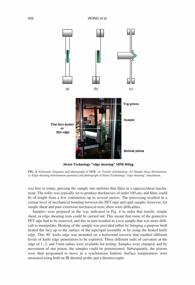
was free to rotate, pressing the sample into uniform thin films in a squeeze/shear mecha-
nism. The roller was typically set to produce thicknesses of order 100 lm, and films could
be of length from a few centimeters up to several meters. The processing resulted in a
certain level of mechanical bonding between the PET tape and opal sample; however, for
simple shear and pure extension mechanical tests, there were difficulties.
Samples were prepared in the way indicated in Fig. 4 in order that tensile, simple
shear, or edge shearing tests could be carried out. This meant that some of the protective
PET tape had to be removed, and this in turn resulted in a test sample that was more diffi-
cult to manipulate. Heating of the sample was provided either by bringing a purpose built
heated flat face up to the surface of the tape/opal assembly or by using the heated knife
edge. This 90� knife edge was mounted on a horizontal traverse that enabled different
levels of knife edge penetration to be explored. Three different radii of curvature at the
edge of 1, 2, and 5 mm radius were available for testing. Samples were clamped, and by
movement of one piston, the samples could be pretensioned. Subsequently, the pistons
were then programed to move in a synchronous fashion. Surface temperatures were
measured using both an IR thermal probe and a thermocouple.
FIG. 4. Schematic diagrams and photograph of MPR. (a) Tensile deformation. (b) Simple shear deformation.
(c) Edge shearing deformation geometry and photograph of Strata Technology “edge shearing” attachment.
402 WONG et al.
V. MPR RESULTS AND OPTICAL INTERROGATION
MPR experiments were carried out under different boundary conditions, and samples
were subsequently optically interrogated at room temperature in order to establish their
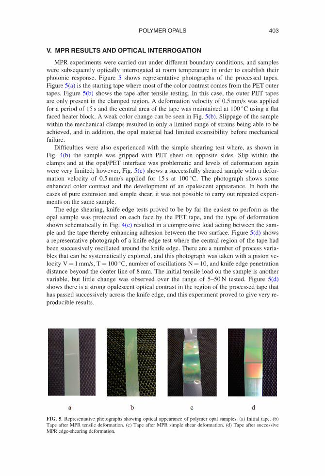
photonic response. Figure 5 shows representative photographs of the processed tapes.
Figure 5(a) is the starting tape where most of the color contrast comes from the PET outer
tapes. Figure 5(b) shows the tape after tensile testing. In this case, the outer PET tapes
are only present in the clamped region. A deformation velocity of 0.5 mm/s was applied
for a period of 15 s and the central area of the tape was maintained at 100 �C using a flat
faced heater block. A weak color change can be seen in Fig. 5(b). Slippage of the sample
within the mechanical clamps resulted in only a limited range of strains being able to be
achieved, and in addition, the opal material had limited extensibility before mechanical
failure.
Difficulties were also experienced with the simple shearing test where, as shown in
Fig. 4(b) the sample was gripped with PET sheet on opposite sides. Slip within the
clamps and at the opal/PET interface was problematic and levels of deformation again
were very limited; however, Fig. 5(c) shows a successfully sheared sample with a defor-
mation velocity of 0.5 mm/s applied for 15 s at 100 �C. The photograph shows some
enhanced color contrast and the development of an opalescent appearance. In both the
cases of pure extension and simple shear, it was not possible to carry out repeated experi-
ments on the same sample.
The edge shearing, knife edge tests proved to be by far the easiest to perform as the
opal sample was protected on each face by the PET tape, and the type of deformation
shown schematically in Fig. 4(c) resulted in a compressive load acting between the sam-
ple and the tape thereby enhancing adhesion between the two surface. Figure 5(d) shows
a representative photograph of a knife edge test where the central region of the tape had
been successively oscillated around the knife edge. There are a number of process varia-
bles that can be systematically explored, and this photograph was taken with a piston ve-
locity V¼ 1 mm/s, T¼ 100 �C, number of oscillations N¼ 10, and knife edge penetration
distance beyond the center line of 8 mm. The initial tensile load on the sample is another
variable, but little change was observed over the range of 5–50 N tested. Figure 5(d)
shows there is a strong opalescent optical contrast in the region of the processed tape that
has passed successively across the knife edge, and this experiment proved to give very re-
producible results.
FIG. 5. Representative photographs showing optical appearance of polymer opal samples. (a) Initial tape. (b)
Tape after MPR tensile deformation. (c) Tape after MPR simple shear deformation. (d) Tape after successive
MPR edge-shearing deformation.
403POLYMER OPALS
In order to make a more quantitative measure of the optical changes, optical reflectiv-
ity spectra was obtained for both faces of the processed opal sample. Measurements were
taken using an adapted Olympus BX51 microscope, using a focused spot diameter of
about 20 lm, with the light signal collected using suitable focusing optics and a fiber-
coupled CCD spectrometer [Finlayson et al. (2011b)]. The spectra were normalized using
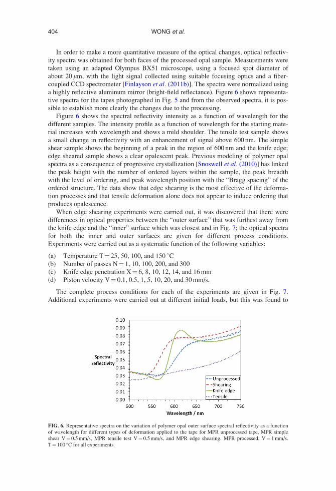
a highly reflective aluminum mirror (bright-field reflectance). Figure 6 shows representa-
tive spectra for the tapes photographed in Fig. 5 and from the observed spectra, it is pos-
sible to establish more clearly the changes due to the processing.
Figure 6 shows the spectral reflectivity intensity as a function of wavelength for the
different samples. The intensity profile as a function of wavelength for the starting mate-
rial increases with wavelength and shows a mild shoulder. The tensile test sample shows
a small change in reflectivity with an enhancement of signal above 600 nm. The simple
shear sample shows the beginning of a peak in the region of 600 nm and the knife edge;
edge sheared sample shows a clear opalescent peak. Previous modeling of polymer opal
spectra as a consequence of progressive crystallization [Snoswell et al. (2010)] has linked
the peak height with the number of ordered layers within the sample, the peak breadth
with the level of ordering, and peak wavelength position with the “Bragg spacing” of the
ordered structure. The data show that edge shearing is the most effective of the deforma-
tion processes and that tensile deformation alone does not appear to induce ordering that
produces opalescence.
When edge shearing experiments were carried out, it was discovered that there were
differences in optical properties between the “outer surface” that was furthest away from
the knife edge and the “inner” surface which was closest and in Fig. 7; the optical spectra
for both the inner and outer surfaces are given for different process conditions.
Experiments were carried out as a systematic function of the following variables:
(a) Temperature T¼ 25, 50, 100, and 150 �C(b) Number of passes N¼ 1, 10, 100, 200, and 300
(c) Knife edge penetration X¼ 6, 8, 10, 12, 14, and 16 mm
(d) Piston velocity V¼ 0.1, 0.5, 1, 5, 10, 20, and 30 mm/s.
The complete process conditions for each of the experiments are given in Fig. 7.
Additional experiments were carried out at different initial loads, but this was found to
FIG. 6. Representative spectra on the variation of polymer opal outer surface spectral reflectivity as a function
of wavelength for different types of deformation applied to the tape for MPR unprocessed tape, MPR simple
shear V¼ 0.5 mm/s, MPR tensile test V¼ 0.5 mm/s, and MPR edge shearing. MPR processed, V¼ 1 mm/s.
T¼ 100 �C for all experiments.
404 WONG et al.
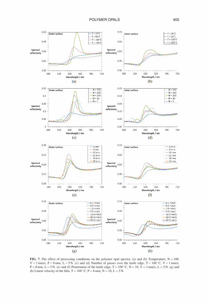
FIG. 7. The effect of processing conditions on the polymer opal spectra: (a) and (b) Temperature, N¼ 100,
V¼ 1 mm/s, P¼ 8 mm, L¼ 5 N. (c) and (d) Number of passes over the knife edge, T¼ 100 �C, V¼ 1 mm/s,
P¼ 8 mm, L¼ 5 N. (e) and (f) Penetration of the knife edge, T¼ 100 �C, N¼ 10, V¼ 1 mm/s, L¼ 5 N. (g) and
(h) Linear velocity of the film, T¼ 100 �C, P¼ 8 mm, N¼ 10, L¼ 5 N.
405POLYMER OPALS
have little effect on the results, and all those reported here were carried out at a 5 N initial
load. Knife edge curvature was also explored and this again was found to have little
effect.
Figures 7(a) and 7(b) show the strong effect that temperature has on the development of
opalescence. For all cases considered, the outer surface effects were stronger than the inner
surface, although the trends for both surfaces were similar. Both at 25 and 150 �C, there
was very little development of opalescence; however, between these two temperatures,
there was a strong effect, with 100 �C experiment showing the largest opalescent peak.
Whilst it was not necessarily surprising that an opalescent peak did not develop at 25 �C, it
was surprising that there was no opalescence at 150 �C. Higher temperatures do promote
thermal motion, and so it is possible that shear-ordered crystalline regions are dissolved at
the higher temperatures once shearing has ceased. The corresponding rheology changes as
a function of temperature that were shown in Fig. 3 did not indicate any significant change
in rheological profile other than a general reduction in modulus with temperature suggest-
ing that the change in opalescence could not be directly detected by a rheology change.
The number of passes also had a significant effect on the observed level of opalescence,
and this is shown in Figs. 7(c) and 7(d). One pass produces a small effect, and maximum
peak height is achieved at 100 passes. After that, the peak height signal decreases with a
further 200 and 300 passes. Again the results are surprising with a clear maximum devel-
oping followed by an unexpected decrease. Colloidal crystallization is known to be
strongly induced by wall effects [see, for example, van Blaaderen et al. (1997)], and in the
polymer opal case, surface growth is believed to develop from the surface into the interior
of the sample with each shear pass. A possible explanation of the decrease from the maxi-
mum may be that the crystallized phase of the opals is stationary with respect to the outer
foils, and it is only the disordered inner part of the phase that flows. As crystal planes de-
velop, growing in from the wall, the ratio of ordered stationary phase and disordered
“flowing” phase changes. This in effect increases the local shear at the boundary between
the disordered and ordered phases throughout crystal growth, despite the fact the bulk
shear conditions are constant. When the stationary crystal phase occupies a large propor-
tion of the sample thickness, local shear at the growing crystal boundary becomes very
large and starts to break up multiple crystal layers causing degradation of the color.
Figures 7(e) and 7(f) show the effect of knife edge penetration, and once again a maxi-
mum was detected within the experimental range. As knife edge penetration increased
from 6 to 12 mm, the opalescent peak height increased. Then for penetration of 14 and
16 mm, there was a progressive decrease. Conceptually, a disordered arrangement of
spheres requires individual sphere to move by up to 0.5 of its diameter relative to its
neighbor to find a location in an ordered lattice. Therefore, it might be expected for shear
strain magnitudes of 0.5 to be optimal for crystallization. Since shear magnitude is con-
trolled by knife edge penetration, this may account for the optimum positions observed.
Finally, the effect of piston velocity is shown in Figs. 7(g) and 7(h). These graphs too
show a peak effect at 1 mm/s with a progressive increase and then decrease in peak height
with increasing piston velocity. The effect of velocity can be interpreted as changing the
shear rate. This impacts on the ordering process by changing the proportion of viscous
and elastic deformation during shear, with only viscous shear producing sphere-sphere
movement and alignment into the ordered crystal state.
For any set of process conditions, the results were essentially reproducible; when
repeated and taken as a whole, the data show a complex, but reproducible sensitivity to
the process variables tested. This in turn suggests that the mechanisms controlling the de-
velopment of ordering is also complex and not directly related to the materials rheology,
which, for example, showed a weak but monotonic effect to temperature.
406 WONG et al.
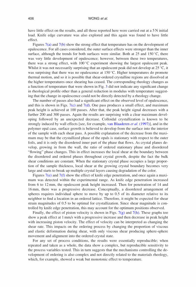
VI. DEFORMATION OF MODEL MATERIAL
The edge shearing, knife edge deformation of the polymer opal sample sandwiched
between plastic sheets is both an unusual and a complicated deformation and so in an
attempt to help understand the type of deformation that had occurred, a model deforma-
tion was carried out using a thicker foamed material.
An initial 3 mm thick polyethylene foam strip was fixed with double sided adhesive
tape to the PET tape. The assembly was then in turn fixed to the pistons of the MPR in
the edge shearing mode and then tensioned. It was possible to draw lines on the edge of
the compressed foamed material as shown in the photographs of Fig. 8 and from this
determine the strain deformation experienced during the edge shearing experiment. From
photographs of the type shown in Fig. 8, it can be seen that the deformation is dominantly
simple shear as initially conjectured by Finlayson et al. (2011b) and the maximum level
of shear strain achieved for the compressed foam sample was of order 0.5. The results
indicate that the model knife-edge shearing was predominantly simple shear, and it is
possible that this is also true for the opal sample which unfortunately could not be tested
in this way because the thickness of the sample was too thin and side view optical obser-
vation was not possible. Because the geometry of the model system is similar for the opal
samples, we believe the dominant type and level of shear strain is similar in both cases,
and this would correspond for the opal tests to an approximate applied shear rate of
0.05 s�1 at the lowest piston speed and 15 s�1 at the highest piston speed.
VII. DISCUSSION AND CONCLUSIONS
The linear viscoelastic rheology of the tested polymer opal samples had rubbery like
properties, and the material was on the edge of processability. Both aspects result in a
rheologically complex material with a high level of elasticity. Normally, the polystyrene
colloidal particles in the solvent-free core shell material would be expected to be disor-
dered; however, shear induced ordering occurs under certain processing conditions.
The ordering of colloidal suspensions in low viscosity matrix fluids has been reported
before [see, for example, Liu et al. (1993)]; however, the transition, even in this relatively
simple fluid, from low shear disorder to intermediate shear order and then potentially
high shear disorder has not been extensively studied, mapped, or modeled. In the case of
polymer opals the situation is even more complex. The high level of elasticity as reported
in this paper resulted in material that was both strain and strain rate dependent. The
FIG. 8. Side view photographic sequence of polymer opal sample being edge sheared from right to left. (a)–(c)
T¼ 25 �C. Piston tape translation velocity¼ 1 mm/s. Approximate thickness of sample¼ 0.5 mm. The photo-
graph shows the V metal edge and the foam, sandwiched between a top and bottom PET tape. The vertical
marker line shown in 7(a) is seen to shear as the sample progressively moves from right to left over the edge as
shown in Figs. 7(b) and 7(c).
407POLYMER OPALS
structure of the solvent-free rubbery material is also complex as the mobile shell phase of
the material is grafted to the core particle. The MPR experimental results indicate that
simple tension did not induce ordering within the material; however, the direct applica-
tion of a single pass simple shear did induce some ordering. Both these experiments suf-
fered from experiment difficulties, and so only very limited experiments were possible
Multiple edge shearing around a knife edge did induce significant ordering. As with low
viscosity matrix suspensions [see, for example, Vermant and Solomom (2005)], the appli-
cation of repeated simple shear oscillations enhances ordering kinetics.
Successive edge shearing proved to be the only effective experimental way of induc-
ing ordering, and this was investigated as a function of a number of process variables.
When each process variable was scanned, an optimum range for opal formation was dis-
covered, namely, a process temperature of 100 �C, 100 oscillations, a knife edge penetra-
tion of 12 mm, and a piston velocity of 1 mm/s. In addition, the outer surface of the opal
sample always showed a stronger opalescence to the inner surface. These results indicate
that ordering kinetics are influenced by a complex series of variables with nucleation and
growth of ordering being controlled by many different factors.
The MPR model edge shearing experiments demonstrated that the main deformation
for edge shearing was simple shear; however, the difference in opalescence for the poly-
mer opal sample between the outer and inner surfaces suggest that the opal deformation
is more complex than the model deformation. The polymer opal edge shear deformation
will have additional factors including compressive squeeze flow deformation and almost
certainly wall slip between the PET and Opal interfaces. The fact that the opalescence on
the top and bottom faces was different for any one set of experiments also highlights
potential differences between the apparently homogeneous simple shear deformation of
the model experiments and a more complex deformation for the opal sample.
Clearly many uncertainties remain in relation to both the Polymer Opal material and
the fact that the unusual edge shearing around a knife edge can be so effective at inducing
opalescent ordering of particles. There is therefore a need for further experiments, and in
particular, there is scope for a rich vein of modeling that can help to understand the defor-
mation, rheology, ordering, and resulting opalescence of this remarkable material.
ACKNOWLEDGMENTS
The authors would like to thank Strata Technology Ltd. and in particular Trevor
Hesketh for the manufacture of the MPR mechanical testing facility and they are also
grateful to DKI for supplying base material. They acknowledge EPSRC Grants
EP/G060649/1, EP/H027130/1, EP/E040241, and EU LINASS 320503.
References
Ackerson, B. J., “Shear induced order and shear processing of model hard sphere suspensions,” J. Rheol. 34(4)
553 (1990).
Ackerson, B. J., and P. N. Pusey, “Shear-induced order in suspensions of hard spheres,” Phys. Rev. Lett. 61(8),
1033–1036 (1988).
Alfrey, T., E. B. Bradford, J. W. Vanderhoff, and G. Oyster, “Optical properties of uniform particle-size
latexes,” J. Opt. Soc. Am. 44, 603–607 (1954).
Catherall, A. A., J. R. Melrose, and R. C. Ball, “Shear thickening and order–disorder effects in concentrated col-
loids at high shear rates,” J. Rheol. 44(1), 1–25 (2000).
Chen, L. B., C. F. Zukoski, B. J. Ackerson, H. J. M. Hanley, G. C. Straty, J. Barker, and C. J. Glinka,
“Structural changes and orientational order in a sheared colloidal suspension,” Phys. Rev. Lett. 69(4),
688–703 (1992).
408 WONG et al.
Dealy, J. M., and J. Wang, Melt Rheology and Its Applications in the Plastics Industry (Springer, Munich, 2013).
Finlayson, C. E., C. Goddard, E. Papachristodoulou, D. R. E. Snoswell, A. Kontogeorgos, P. Spahn, G. P.
Hellmann, O. Hess, and J. J. Baumberg, “Ordering in stretch tunable polymeric opal fibers,” Opt. Express
19, 3144–3154 (2011a).
Finlayson, C. E., and J. J. Baumberg, “Polymer opals as novel photonic materials,” Polym. Int. 62(10),
1403–1407 (2013).
Finlayson, C. E., P. Spahn, D. R. E. Snoswell, G. Yates, A. Kontogeorgos, A. I. Haines, G. P. Hellmann, and J.
J. Baumberg, “3D bulk ordering in macroscopic solid opaline films by edge-induced rotational shearing,”
Adv. Mater. 23, 1540–1544 (2011b).
Hachisu, S., Y. Kobayashi, and A. D. Kose, “Phase separation in monodisperse latexes,” J. Colloid Interface
Sci. 42(2), 342 (1973).
Haw, M. D., W. C. K. Poon, and P. N. Pusey, “Direct observation of oscillatory-shear-induced order in colloidal
suspensions,” Phys. Rev. E 57(6), 6859–6864 (1998).
Koumakis, N., A. B. Schofield, and G. Petekidis, “Effects of shear induced crystallization on the rheology and
ageing of hard sphere glasses,” Soft Matter 4, 2008–2018 (2008).
Kramb, R. C., and C. F. Zukoskia, “Nonlinear rheology and yielding in dense suspensions of hard anisotropic
colloids,” J. Rheol. 55(5), 1069–1084 (2011).
Liu, A. J., and S. R. Nagel, “Granular and jammed materials,” Soft Matter 6, 2869–2870 (2010).
Liu, J., D. A. Weitz, and B. J. Ackerson, “Coherent crystallography of shear-aligned crystals of hard-sphere
colloids,” Phys. Rev. E 48(2), 1106–1114 (1993).
Mackley, M. R., and D. G. Hassell, “The multipass rheometer: A review,” J. Non-Newtonian Fluid Mech.
166(9-10), 421–456 (2011).
Mackley, M. R., R. T. J. Marshall, and J. B. A. F. Smeulders, “The multipass rheometer,” J. Rheol. 39(6),
1293–1309 (1995).
McMullan, J. M., and N. J. Wagner, “Directed self-assembly of suspensions by large amplitude oscillatory shear
flow,” J. Rheol. 53(3), 575–588 (2009).
Mewis, J., W. J. Frith, T. A. Strivens, and W. B. Russel, “The rheology of suspensions containing polymerically
stabilized particles,” AIChE J. 35(3), 415–422 (1989).
Pursiainen, O. L. J., J. J. Baumberg, H. Winkler, B. Viel, P. Spahn, and T. Ruhl, “Nanoparticle-tuned structural
color from polymer opals,” Opt. Express 15(15), 9552–9561 (2007).
Pursiainen, O. L. J., J. J. Baumberg, H. Winkler, B. Viel, and T. Ruhl, “Compact strain-sensitive flexible pho-
tonic crystals for sensors,” Appl. Phys. Lett. 87(10), 1902–1905 (2005).
Ruhl, T., P. Spahn, and G. P. Hellmann, “Artificial opals prepared by melt compression,” Polymer 44,
7625–7634 (2003).
Ruhl, T., P. Spahn, H. Winkler, and G. P. Hellmann, “Large area monodomain order in colloidal crystals,”
Macromol. Chem. Phys. 205, 1385–1393 (2004).
Snoswell, D. R. E., A. Kontogeorgos, J. J. Baumberg, T. D. Lord M. R. Mackley, P. Spahn, and G. P. Hellmann,
“Shear ordering in polymer photonic crystals,” Phys. Rev. E 81, 020401 (2010).
Spahn, P., C. E. Finlayson, W. Mbi Etah, D. R. E. Snoswell, J. J. Baumberg, and G. P. Hellmann, “Modification
of the refractive-index contrast in polymer opal films,” J. Mater. Chem. 21, 8893–8897 (2011).
Sussman, J., D. R. E. Snoswell, A. Kontogeorgos, J. J. Baumberg, and P. Spahn, “Thermochromic polymer
opals,” Appl. Phys. Lett. 95(17), 173116 (2009).
Trappe, V., V. Prasad, L. Cipelletti, P. N. Segre, and D. A. Weitz, “Jamming phase diagram for attractive parti-
cles,” Nature 411(14), 772–775 (2001).
van Blaaderen, A., R. Ruel, and P. Wiltzius, “Template directed colloidal crystallisation,” Nature 385, 321–324
(1997).
Vermant, J., and M. J. Solomon, “Flow-induced structure in colloidal suspensions,” J. Phys.: Condens. Matter
17, 187–216 (2005).
Viel, B., T. Ruhl, and G. P. Hellmann, “Reversible deformation of opal elastomer,” Chem. Mater. 19,
5673–5679 (2007).
White, J. L., and K. J. Kim, Thermoplastic and Rubber Compounds: Technology and Physical Chemistry
(Hanser, Munich, 2007–2008).
409POLYMER OPALS