the resicon range - chemical and steel anchor systems for ... catalogue lo res.pdf · welcome to...
38
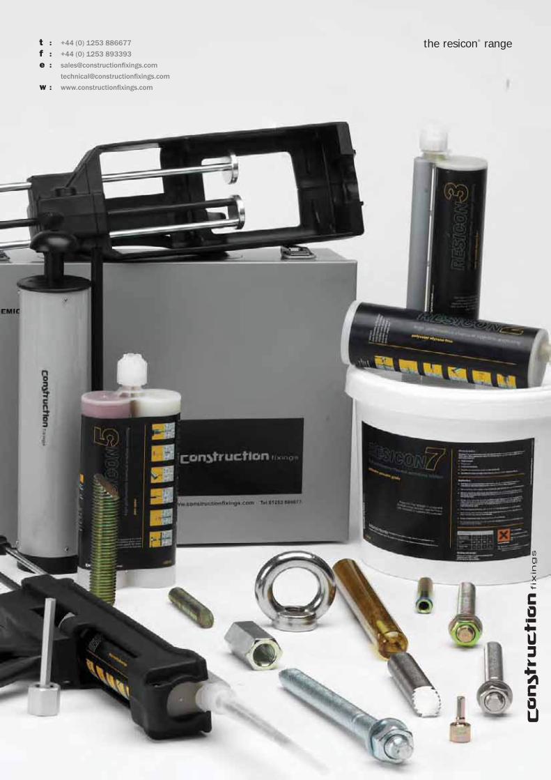
the resicon ® range chemical anchoring for industry
Transcript of the resicon range - chemical and steel anchor systems for ... catalogue lo res.pdf · welcome to...

the resicon® range
chemical anchoring for industry

welcome to the resicon range of chemical anchor systems for heavy duty anchoring in masonry and concrete.
our resins are manufactured in Europe to ISO 9001 standards using only the highest quality materials and using the latest blending, formulation and batch testing technology to ensure consistent high load performance.
resicon is sold worldwide throughout the construction and civil engineering industries andis regularly specifi ed by architects and structural engineers for load critical structural applications and high profi le domestic and international projects.
we hope you fi nd our chemical anchor catalogue informative, our sales and technical departments are always available for general advice and to answer any queries you may have about chemical anchoring and the resicon range.
for more information about our company and details of our complete fi xings range please visit our website.
t : +44 (0) 121 506 6300f : +44 (0) 121 506 6301 e : sales@constructionfi xings.com
technical@constructionfi xings.com
w : www.constructionfi xings.com
chem
ical
anc
horin
g
welcome to the resicon® range

contents
www: constructionf xings.com
chem
ical
anc
horin
g
1 - 4
9 - 12
13 - 16
17 - 18
19 - 22
23 - 30
31 - 32
5 - 8
technical information introduction to chemical anchoring
resicon3 epoxy acrylate injection resin styrene free
resicon5 pure epoxy injection resin
resicon7 polyester pourable resin
resicon si epoxy acrylate spin-in glass capsules
resicon2 polyester injection resin styrene free
resicon accessories installation accessories
resicon fi xings steel fi xings for use with resicon resins
t : +44 (0) 121 506 6300

technical information
1
www: constructionf xings.com
chem
ical
anc
horin
g
t : +44 (0) 121 506 6300
what are chemical anchors :
In simple terms, chemical or resin anchors are generic descriptions relating to steel studs, bolts or fi xings which are bonded into a substrate, usually masonry and concrete, using a resin based adhesive system. Ideally suited for high load applications, in virtually all cases the resulting bond is stronger than the base material itself and as the system is based on chemical adhesion, no load stress is imparted to the base material as with expansion type anchors. All systems operate using the same principle with the base resin requiring the introduction, by mixing, of a second component to begin the chemical curing process, hence the term chemical anchor.
Not all resins are the same and there are many different systems available in the market using a wide range of delivery systems and although all systems operate on the same basic principle, there are several differing blend formulations and chemical components usually designed by the manufacturer for specifi c performance criteria in differing applications and substrates e.g. high strength, low shrink, solvent free, high temperature, fast and slow cure etc.
resin formulations :
There are 2 basic resin families, catalytic and non-catalytic, the difference being catalytic resins use a 2 component resin and catalyst at ratios of approximately 10:1 and it is this catalyst that initiates the curing process. The chemical reaction of the 2 components when mixed propagates throughout the mix as long as the base resin is in contact with any amount of the catalyst, the advantages of these resins are that mix proportions are not critical and they are generally less expensive due to the lesser amounts of catalyst required per mix volume. Catalytic resins for chemical anchoring are again broken down into several types such as polyester, vinylester, epoxy acrylate and methacrylate etc. dependant on the manufacturers formulation, all offer differing advantages and performance, for the resicon range we use polyester and epoxy acrylate with epoxy acrylate being the highest performer of the two for strength, durability and load testing.
Non-catalytic resins, generally mixed in 1:1 ratios, cure only when equal amounts of the 2 components are in direct contact and the chemical reaction does not spread throughout the mix as with catalytic resins, they are generally therefore only supplied as an injection system as this automatically dispenses the correct amount of each component into the mixing nozzle ensuring a thorough controlled mix has occurred prior to injection.
Pure epoxy resin is the only non-catalytic resin currently in use for chemical anchoring. Epoxy resins cure slower than catalytic resins, however generally have superior mechanical and adhesive properties allowing higher loading and a stronger bond, epoxy is also virtually 100% non shrink and is therefore more suitable for larger holes and is generally (certainly for resicon5) suitable for underwater applications due to its water impervious nature.
Injection cartridge systems are the most widely used format and consist of 2 resin components in separate compartments of a cartridge which mix proportionally in the supplied nozzle when pumped using the specifi c applicator gun for each type, this is a very versatile delivery system as more or less resin may be applied per anchor dependant on the application and it can be used with variable types and sizes of anchor bolts and fi xings, the resulting non sag mix makes this system the preferred choice for horizontal and overhead installations and perforated and hollow masonry.
Glass capsule systems consist of a resin, a quartz sand aggregate and a catalyst (in a secondary vial) all metered and factory sealed in a glass capsule for mixing in the hole with a specifi c anchor stud, the stud is driven through the capsule using a drilling machine, smashing the glass which then also forms part of the aggregate. Glass capsule systems provide high bond strengths due in part to the larger aggregate size in comparison to the fi ner aggregates used for injection systems and they are a simple cost effective method of chemical anchoring. Glass capsule systems are generally viscous in nature, prior to mixing, and can be unsuitable for overhead installations and hollow masonry.
Free mix systems are usually of the pourable type and consist of 2 separately packaged components for mixing on site either by hand or by machine using a mixing paddle. These systems are generally used where large deep holes require volume fi lling and where injection systems would be uneconomical or diffi cult to use, the system is also useful for bonding ir-regular shapes to or in concrete and masonry such as columns, ballustrades, assemblies and baseplates. Specifi c care must be taken with this type of system to ensure the components are mixed in the correct volumes, due to the viscous nature they are generally only used for vertical downward holes.
chemical anchor formats :

installing chemical anchors :
All types of resin anchors rely on a structural surface contact bond between both the anchor rod and resin and the resin and the drill hole wall, resins will only bond to the dust particles on the side walls and base of a drillhole and not the main substrate in poorly prepared holes. It is therefore vital that holes are thoroughly cleaned by blowing out and brushing prior to anchor installation. Hole diameters and depths should also be clearly observed depending on the resin system used and installation guidelines should be strictly adhered to.
failures :
chemical anchoring is an extremely versatile and adaptive method of providing high load structural connections with very few failures. From historical testing and site inspection we have established without doubt that the single most common cause of anchor failures are poor hole preparation and cleaning. Other less common failures include incorrect hole diameters, use of out of date material and lack of observation of cure times. All resicon resins have detailed installation guidelines and should be followed to ensure trouble free installation and optimum anchor performance.
the resicon range :
the resicon range has been developed specifi cally for the construction and civil engineering industries where consistent high performance is a pre-requisite and we offer several resin types in differing delivery systems to suit variable site applications. Our formulations are designed specifi cally to provide high strength and a fast cure inconcrete, rock, stone and masonry and all test and load data is determined by ongoing detailed independent laboratory testing. We take our environmental responsibilities and operator safety seriously and therefore you will fi nd our range consists predominantly of higher quality than standard, styrene free (non toxic) low odour base materials and full material safety data sheets are available on request.
which one should I use :
The choice of chemical anchors can appear initially confusing and it is important to differentiate between the available types. We offer three types of delivery system, injection cartridges, a glass capsule system and a free mix pourable grade.
Resicon7 is a free mix pouring grade resin and is currently only available in a polyester format and therefore there are no further options for this system.Resicon SI is our glass capsule system and to suit our performance criteria is based on a higher performing epoxy acrylate rather than a polyester resin.
Resicon cartridge systems are also further broken down into 3 grades, due to each resin having differing characteristics, and load performance to suit the various applications and areas of industry in which they are used. Technical data for each system is available throughout this guide and you will see the performance values increase for each resin as you progress. As a general guideline :
resicon2 : polyester based, low cost resin suitable for brickwork and general purpose use in concrete.resicon3 : epoxy acrylate based resin for medium to heavy duty anchoring in concrete and the most specifi ed product in our range.resicon5 : pure epoxy premium grade resin and our highest performing system for heavy duty structural anchoring.
In brief, the choice of system is largely dependant on the application or design criteria and the nature of the item to be anchored, however as a general guide the following should be considered prior to selection: required delivery systemtype of anchor usednature of substrateload requirements
Should you require any assistance with specifi cation, or any further information about the resicon range, please contact our technical department.
www: constructionf xings.com
2
chem
ical
anc
horin
g
technical information
t : +44 (0) 121 506 6300
the advantages of chemical anchoring
In comparison with steel expansion anchors, chemical anchors provide a considerably stronger bond and therefore higher loadings per anchor can be achieved on a like for like size basis. This is largely due to the fact a single point expansion anchor relies on a friction hold to the drill hole wall from an expanding segment within the bolt. Generally this segment may only account for 1/4 to 1/3 of the bolt length in the drillhole whereas a chemical anchor forms a permanent bond with the between the fi xing element and base material for the full length of the installed anchor with the resin usually being stronger than the base material itself.
Chemical anchors do not impart any expansion stresses on the substrate and can therefore be placed closer together in groups and closer to substrate edges than is possible with other methods, they are very versatile in application and can be used in a variety of substrates including concrete, stone, rock, aerated concrete, solid and hollow brick and block and weak and friable materials. The resicon range is chemically and vibration resistant and all systems offer good corrosion and fi re protection as the anchor rod is fully encased in solid resin.
bond range
grip range

NR
D
V
N : tension V : shear D : compression R : oblique (combined)
The 4 main loads applicable to an anchor are tension, shear , compression and oblique or combined load, usually expressed as a fi gure in kilonewtons (Kn).
types of load :
our load data explained :
In recent years load data for anchoring in construction has been subject to substantial changes, whereas loads for a particular fi xing would be calculated using the Global Safety Factor Method with results expressed as ultimate load and recommended loads, in accordance with the latest Eurocode we now use the Partial Safety Factor Method and results are now expressed as ultimate resistance, design resistance and recommended load, for those unfamiliar with the concept these loads are explained as follows :
Characteristic resistance : this is the ultimate load the anchor can achieve before failure with a statistical probability factor applied (95% fractile).Design resistance : this is the characteristic resistance divided by partial safety factors for the materials used, determined from testing and in accordance with current EOTA guidelines Recommended load : this is the design action divided by a further partial safety factor to give a working design or recommended load.
Engineers who prefer the use of the Global Safety Factor Method may continue to do so using the recommended load values.
Whichever system is adopted for calculation purposes it is vital for those new to anchoring to understand the differences in data. Ultimate loads are the maximum values an anchor has reached under test conditions before total failure with no safety factor applied, recommended loads are the ultimate loads divided by a safety factor (average of 3) and represent the safe working load.
γ F
ultimate load χ ultimate resistance Frum
partial safety factor methodglobal safety factor method
Recommended load Frec
χ - KS v
design action Fsd
design resistance Frd
γ M
characteristic resistance95% fractile Frk
actual design load Sact
Sac
t <
F
rec
Fsd
<
F
rd
K : statistical confi dence factor S : standard deviationV : global safety factorγ M : partial resistance safety factor - materialsγ F : partial resistance safety factor - load
3
www: constructionf xings.com
chem
ical
anc
horin
g
t : +44 (0) 121 506 6300
technical information

anchor spacing and edge distances
the centre spacings and distances anchors are placed from a free edge have a dramatic effect on the load which can be safely applied to the fi xing. Once installed, anchors promote a radiating load stress effect on the base material which can be a considerable size on the surface and which diminish to the base of the bolt forming a cone shape. The performance of the anchor may be increased by using deeper embedment depths which create a larger stress cone, however placing anchors close together or close to the substrate edge will reduce the cone size and subsequently the performance of the fi xing.
Ideally anchors should be placed in accordance with the minimum characteristic edge and centre spacing given in our tables, where this is not feasible we have provided reduction tables for each product and this data should be applied to the recommended load or design resistance to give a reduced performance indicator.
example
Recommended tensile load for an M12 anchor stud using Resicon3 is 13.71KnCharacteristic spacing is 140mmActual spacing used is 100mmCentre spacing reduction factor in 30Nmm2 concrete is 0.88
Therefore new recommended load is 13.71 x 0.88 = 12.07Kn
reduced centre spacing reduced edge distance
Key
Glossary of terms used throughout our catalogue
bo standard embedment depthCcr,N characteristic edge distance in tensionCcr,V characteristic edge distance in sheard thread diameterdo hole diameter in concretedf hole diameter in fi xtureFrec recommended loadhef minimum effective anchorage depthhmin thickness of substratel standard lengthNrk characteristic resistance in tension Nrd design resistance in tension Nrec recommended load in tensionVrk characteristic resistance in shearVrd design resistance in shearVrec recommended load in shearScr characteristic centre spacingt inst recommended torque
our calculations explained
Our calculations are derived using the latest partial safety factor method and our load data is calculated in accordance with the following EOTA guidelines :
To use this method we must verify that the design value (action) of the required load is less than the design value of resistance Fsd < Frd
To calculate a safety factor inclusive recommended tensile load in concrete we take the characteristic resistance which is obtained from the ultimate resistance divided by a confi dence factor of 95% and divide this fi gure by a partial resistance safety factor of 2.5, this fi gure is obtained from the formula γ Mc = γc . γ1 . γ2
where γc equals partial safety factor for concrete under compression : 1.5 γ1 equals partial safety factor taking into account the scatter of the tensile strength of the concrete across the site : 1.2 for concrete produced and cured with normal care (eurocode 2) γ2 equals partial safety factor taking into account the installation safety of an anchor system : 1.4 for tensile load
The resulting fi gure then becomes the design resistance which is divided by a further safety factor for the load γ F : 1.4 to give the recommended load.
www: constructionf xings.com
4
chem
ical
anc
horin
g
t : +44 (0) 121 506 6300
technical information
All information detailed in our catalogue is based on technical approvals, formulas
and site and laboratory testing under optimum conditions and include a stated
safety factor. As we have no direct or indirect control over where or how our
products are applied or installed, we do not accept any liability either directly or
indirectly arising from the use of our products, whether or not in accordance with
any advice, specifi cation or recommendation given by us. If in any doubt we
recommend site testing of all products for suitability and consultation with a suitably
qualifi ed structural engineer for safety critical and structural applications.

resicon2
5
www: constructionf xings.com
chem
ical
anc
horin
g
t : +44 (0) 121 506 6300
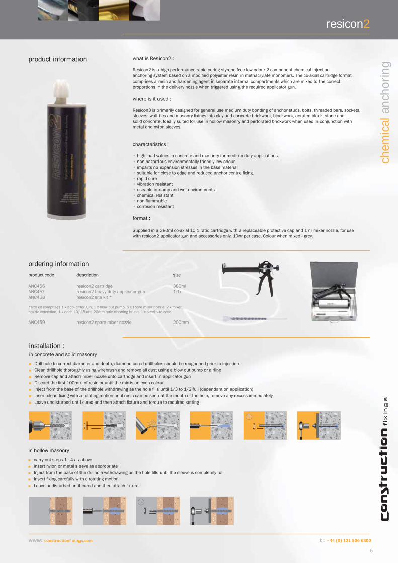
what is Resicon2 :
Resicon2 is a high performance rapid curing styrene free low odour 2 component chemical injection anchoring system based on a modifi ed polyester resin in methacrylate monomers. The co-axial cartridge formatcomprises a resin and hardening agent in separate internal compartments which are mixed to the correct proportions in the delivery nozzle when triggered using the required applicator gun.
where is it used :
Resicon3 is primarily designed for general use medium duty bonding of anchor studs, bolts, threaded bars, sockets, sleeves, wall ties and masonry fi xings into clay and concrete brickwork, blockwork, aerated block, stone and solid concrete. Ideally suited for use in hollow masonry and perforated brickwork when used in conjunction with metal and nylon sleeves.
characteristics :
• high load values in concrete and masonry for medium duty applications.• non hazardous environmentally friendly low odour• imparts no expansion stresses in the base material• suitable for close to edge and reduced anchor centre fi xing.• rapid cure• vibration resistant• useable in damp and wet environments• chemical resistant• non fl ammable• corrosion resistant
format :
Supplied in a 380ml co-axial 10:1 ratio cartridge with a replaceable protective cap and 1 nr mixer nozzle, for use with resicon2 applicator gun and accessories only. 10nr per case. Colour when mixed - grey.
product information
installation :in concrete and solid masonry
Drill hole to correct diameter and depth, diamond cored drillholes should be roughened prior to injection Clean drillhole thoroughly using wirebrush and remove all dust using a blow out pump or airline Remove cap and attach mixer nozzle onto cartridge and insert in applicator gun Discard the fi rst 100mm of resin or until the mix is an even colour Inject from the base of the drillhole withdrawing as the hole fi lls until 1/3 to 1/2 full (dependant on application) Insert clean fi xing with a rotating motion until resin can be seen at the mouth of the hole, remove any excess immediately Leave undisturbed until cured and then attach fi xture and torque to required setting
ordering information
product code description size
ANC456 resicon2 cartridge 380mlANC457 resicon2 heavy duty applicator gun 1:1rANC458 resicon2 site kit *
*site kit comprises 1 x applicator gun, 1 x blow out pump, 5 x spare mixer nozzle, 2 x mixernozzle extension, 1 x each 10, 15 and 20mm hole cleaning brush, 1 x steel site case.
ANC459 resicon2 spare mixer nozzle 200mm
resicon2
in hollow masonry
carry out steps 1 - 4 as above insert nylon or metal sleeve as appropriate Inject from the base of the drillhole withdrawing as the hole fi lls until the sleeve is completely full Insert fi xing carefully with a rotating motion Leave undisturbed until cured and then attach fi xture
www: constructionf xings.com
6
chem
ical
anc
horin
g
t : +44 (0) 121 506 6300

cartridge and stud data
technical information
Thread diameter : mm (d)
Standard stud length : mm (l)
Standard embedment : mm (bo)
Hole diameter concrete : mm (do)
Substratethickness min : mm (hmin)
Hole diameter in fi xture : mm (df)
Recommended torque : Nm (Tinst)
No of fi xings per cartridge :(approx)
M8 110 80 10 110 9 11 90
M10 130 90 12 120 11 22 58
M12 160 110 14 140 13 38 48
M16 190 125 18 165 17 95 20
M20 260 170 24 220 22 170 8
M24 300 210 28 270 26 260 5
M30 380 280 35 340 33 480 3
Size Characteristic resistance : kN Design resistance : kN Recommended load kN
Tension : (NRk) Shear : (VRk) Tension : (NRd) Shear : (VRd) Tension : (Nrec) Shear : (Vrec)
M8 15.15 10.10 6.06 8.08 4.33 5.77
M10 22.38 15.60 8.95 12.48 6.39 8.91
M12 30.38 23.10 12.15 18.48 8.68 13.20
M16 51.90 41.80 20.76 33.44 14.83 23.89
M20 76.35 66.80 31.34 53.44 22.39 38.17
M24 102.90 95.70 41.46 76.56 29.61 54.69
M30 160.43 153.00 72.17 122.40 51.55 87.43
Embedment depths are typical when using standard anchor studs and are for guidance only, deeper embedment depths may be adopted to suit the application and the length of anchor used.
performance data
All load data calculated using the Partial Safety Factor concept and to Eurocode 1 standard. For engineers preferring to use the Global Safety factor approach the characteristic resistance loads are 95% of the Ultimate load values and recommended loads remain constant for both methods.
resicon2
for concrete :C20/25 - 30Nmm2 using standard embedment depths and 5.8Gr steel anchor studs in clean blown and brushed drill holes.
Size Recommended load : kN
20.5 N/mm2 Brickwork 3.5 N/mm2 Brickwork 7 N/mm2 Blockwork 2.8 N/mm2 Blockwork
M8 1.50 0.50 0.80 0.55
M10 3.00 0.95 1.50 0.65
M12 4.20 1.20 2.40 0.95
M16 5.10 3.20
due to the drill sizes required and potential weakening of the base material we do not recommend installation of anchors above 16mm in 20.5 N/mm2 brickwork and 7 N/mm2 blockwork or above 12mm in 3.5 N/mm2 brickwork and 2.8 N/mm2 blockwork
for masonry :using standard embedment depths and 5.8Gr steel anchor studs in clean blown and brushed drill holes.
7
www: constructionf xings.com
chem
ical
anc
horin
g
t : +44 (0 ) 121 506 6300

Size Characteristic edge distance : mm (C) Characteristic spacing : mm (S)
Tension : (Ccr,N) Shear : (Ccr,V) Tension and shear : (Scr)
M8 80 100 100
M10 90 130 130
M12 110 150 140
M16 130 170 170
M20 150 190 210
M24 190 240 240
M30 300 350 350
edge distance and spacingsEdge and anchor centre spacings quoted are the minimum distances required either between anchors or an anchors distance from the substrates free edge to achieve the load values detailed (in concrete)
reduction factors
Where characteristic edge and spacing distances are not achievable and closer spacings are required, the appropriate reduction factor from the following tables must be applied to the Design Resistance or Recommended Load.
To use the tables select the required bolt diameter across the top of the table and the actual edge or spacing distance from the left column. The fi gure at the intersecting point is the Reduction Factor and should be multiplied by the Design Resistance or the Recommended Load to give the correct load data for the required spacing.
edge distance
Edge distance - remote from a free edge : mm
Tensile load : edge reduction factors Shear load : edge reduction factors
M8 M10 M12 M16 M20 M24 M8 M10 M12 M16 M20 M24
50 0.77 0.50
60 0.85 0.80 0.60 0.50
70 0.92 0.87 0.78 0.70 0.58 0.50
80 1.00 0.93 0.84 0.80 0.66 0.57
90 1.00 0.89 0.82 0.90 0.75 0.64 0.56
100 0.95 0.86 0.80 1.00 0.83 0.71 0.62 0.56
110 1.00 0.91 0.84 0.77 0.92 0.78 0.69 0.61 0.50
130 1.00 0.92 0.83 1.00 0.92 0.81 0.72 0.59
150 1.00 0.90 1.00 0.94 0.83 0.68
170 0.97 1.00 0.94 0.77
190 1.00 1.00 0.86
210 0.95
240 1.00
Spacing distances : mm
Tensile and Shear load reduction factors
M8 M10 M12 M16 M20 M24
50 0.80
60 0.84 0.80
70 0.88 0.83 0.80
80 0.92 0.87 0.83
90 0.96 0.90 0.86 0.81
100 1.00 0.93 0.88 0.84 0.80
110 0.97 0.91 0.86 0.82 0.79
130 1.00 0.97 0.91 0.86 0.82
150 1.00 0.95 0.90 0.85
170 1.00 0.94 0.88
190 0.98 0.92
210 1.00 0.95
240 1.00
Substratetemperature : 0C
Gel Time : mins Minimum load time : mins
25 3 30
15 6 35
5 12 50
-5 50 90
Full cure achieved after 6 - 24 hours dependant on site conditions, however fi xtures may be installed after the minimum load time has elapsed
curing timescentre spacing
compressive strength ASTM 695 - 48 N/mm2
tensile strength ASTM 638 - >10 N/mm2
fl exural strength ASTM 790 - 20 N/mm2
elastic modulus - 4206 N/mm2
fl exural modulus - 3238 N/mm2
mixed density - 1.65 g/cm3
ultimate physical properties
Store in dry conditions in original packaging in a well ventilated area +50C to +250C. Do not expose to direct sunlight, storage at higher temperatures may reduce the product shelf life.
In C20/25 - 30Nmm2 concrete
In C20/25 - 30Nmm2 concrete
www: constructionf xings.com
8
chem
ical
anc
horin
g
t : +44 (0) 121 506 6300
resicon2

resicon3
9
www: constructionf xings.com
chem
ical
anc
horin
g
t : +44 (0) 121 506 6300
resicon3
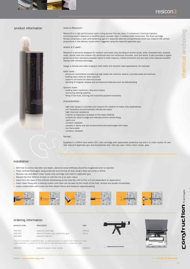
what is Resicon3 :
Resicon3 is a high performance rapid curing styrene free low odour 2 component chemical injection anchoring system based on a modifi ed epoxy acrylate resin in methacrylate monomers. The dual cartridge format comprises a resin and hardening agent in separate external compartments which are mixed to the correct proportions in the delivery nozzle when triggered using the required applicator gun.
where is it used :
Resicon3 is primarily designed for medium and heavy duty bonding of anchor studs, bolts, threaded bars, sockets, rebar, starter bars and dowels into reinforced and non-reinforced concrete, rock and stone. It also provides a higher grade bond than standard polyester resins in solid masonry, hollow brickwork and pre-cast units (requires suitable sleeve) with minimal shrinkage.
Usage is diverse and wide ranging in both static and dynamic load applications, for example
static loads : • structural connections transferring high loads into columns, beams, concrete pads and sections• holding down bolts for steel columns• masonry tie backs for steel structures• bonding of irregular shapes and architectural features such as ballustrading
dynamic loads : • holding down machinery, fans and motors• anchoring racking systems• fi xing of services, ducting and industrial pipework bracketry
characteristics :
• high load values in concrete and masonry for medium to heavy duty applications.• non hazardous environmentally friendly low odour• high chemical resistance• imparts no expansion stresses on the base material• suitable for close to edge and reduced anchor centre fi xing.• rapid cure• vibration resistant• useable in damp and wet environments and submerged drill holes • non fl ammable• corrosion resistant
format :
Supplied in a 345ml dual action 10:1 ratio cartridge with replaceable protective cap and 1 nr mixer nozzle, for use with resicon3 applicator gun and accessories only. 12nr per case. Colour when mixed - grey.
product information
installation :
Drill hole to correct diameter and depth, diamond cored drillholes should be roughened prior to injection Clean drillhole thoroughly using wirebrush and remove all dust using a blow out pump or airline Remove cap and attach mixer nozzle onto cartridge and insert in applicator gun Discard the fi rst 100mm of resin or until the mix is an even colour Inject from the base of the drillhole withdrawing as the hole fi lls until 1/3 to 1/2 full (dependant on application) Insert clean fi xing with a rotating motion until resin can be seen at the mouth of the hole, remove any excess immediately Leave undisturbed until cured and then attach fi xture and torque to required setting
ordering information
product code description size
ANC462 resicon3 cartridge 345mlANC463 resicon3 heavy duty applicator gun 10:1rANC464 resicon3 site kit *
*site kit comprises 1 x applicator gun, 1 x blow out pump, 5 x spare mixer nozzle, 2 x mixernozzle extension, 1 x each 10, 15 and 20mm hole cleaning brush, 1 x steel site case.
ANC459 resicon3 spare mixer nozzle 200mm
www: constructionf xings.com
10
chem
ical
anc
horin
g
t : +44 (0) 121 506 6300

resicon3
cartridge and stud data
technical information
Thread diameter : mm (d)
Standard stud length : mm (l)
Standard embedment : mm (bo)
Hole diameter concrete : mm (do)
Substratethickness min : mm (hmin)
Hole diameter in fi xture : mm (df)
Recommended torque : Nm (Tinst)
No of fi xings per cartridge :(approx)
M8 110 80 10 110 9 11 72
M10 130 90 12 120 11 22 54
M12 160 110 14 140 13 38 36
M16 190 125 18 165 17 95 20
M20 260 170 24 220 22 170 6
M24 300 210 28 270 26 260 5
M30 380 280 35 340 33 480 2
Size Characteristic resistance : kN Design resistance : kN Recommended load kN
Tension : (NRk) Shear : (VRk) Tension : (NRd) Shear : (VRd) Tension : (Nrec) Shear : (Vrec)
M8 19.98 10.10 7.99 8.08 5.71 5.77
M10 32.94 15.60 13.18 12.48 9.41 8.91
M12 47.98 23.10 19.19 18.48 13.71 13.20
M16 71.10 41.80 28.44 33.44 20.31 23.89
M20 101.30 66.80 40.52 53.44 28.94 38.17
M24 129.77 95.70 51.91 76.56 37.08 54.69
M30 201.60 153.00 80.64 122.40 57.60 87.43
Size Characteristic edge distance : mm (C) Characteristic spacing : mm (S)
Tension : (Ccr,N) Shear : (Ccr,V) Tension and shear : (Scr)
M8 80 100 100
M10 90 130 130
M12 110 150 140
M16 130 170 170
M20 150 190 210
M24 190 240 240
M30 300 350 350
Embedment depths are typical when using standard anchor studs and are for guidance only, deeper embedment depths may be adopted to suit the application and the length of anchor used.
performance data
All load data calculated using the Partial Safety Factor concept and to Eurocode 1 standard. For engineers preferring to use the Global Safety Factor approach the Characteristic Resistance loads are 95% of the Ultimate load values and Recommended Loads remain constant for both methods.
edge distance and spacings
Edge and anchor centre spacings quoted are the minimum distances required either between anchors or an anchors distance from the substrates free edge to achieve the load values detailed above in concrete
In C20/25 - 30Nmm2 concrete using standard embedment depths and 5.8Gr steel anchor studs in clean blown and brushed drill holes.
In C20/25 - 30Nmm2 concrete
11
www: constructionf xings.com
chem
ical
anc
horin
g
t : +44 (0) 121 506 6300
Edge distance - remote from a free edge : mm
Tensile load : edge reduction factors Shear load : edge reduction factors
M8 M10 M12 M16 M20 M24 M8 M10 M12 M16 M20 M24
50 0.77 0.50
60 0.85 0.80 0.60 0.50
70 0.92 0.87 0.78 0.70 0.58 0.50
80 1.00 0.93 0.84 0.80 0.66 0.57
90 1.00 0.89 0.82 0.90 0.75 0.64 0.56
100 0.95 0.86 0.80 1.00 0.83 0.71 0.62 0.56
110 1.00 0.91 0.84 0.77 0.92 0.78 0.69 0.61 0.50
130 1.00 0.92 0.83 1.00 0.92 0.81 0.72 0.59
150 1.00 0.90 1.00 0.94 0.83 0.68
170 0.97 1.00 0.94 0.77
190 1.00 1.00 0.86
210 0.95
240 1.00
Spacing distances : mm
Tensile and Shear load reduction factors
M8 M10 M12 M16 M20 M24
50 0.80
60 0.84 0.80
70 0.88 0.83 0.80
80 0.92 0.87 0.83
90 0.96 0.90 0.86 0.81
100 1.00 0.93 0.88 0.84 0.80
110 0.97 0.91 0.86 0.82 0.79
130 1.00 0.97 0.91 0.86 0.82
150 1.00 0.95 0.90 0.85
170 1.00 0.94 0.88
190 0.98 0.92
210 1.00 0.95
240 1.00
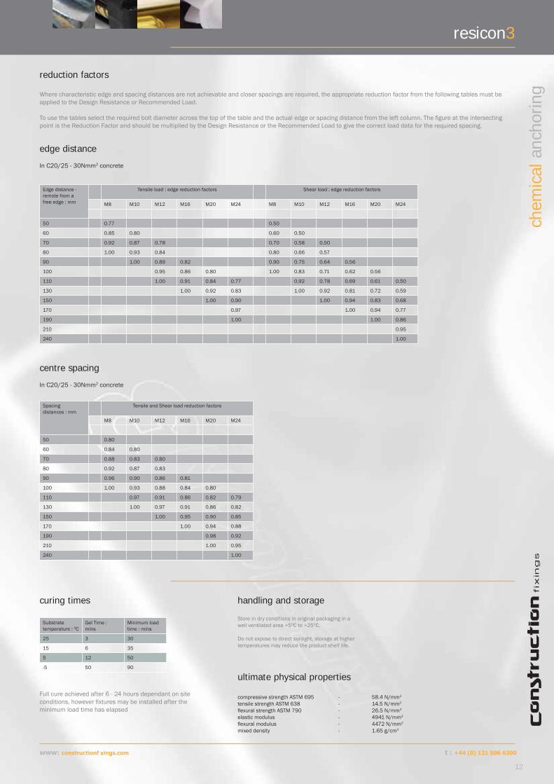
reduction factors
Substratetemperature : 0C
Gel Time : mins
Minimum load time : mins
25 3 30
15 6 35
5 12 50
-5 50 90
Full cure achieved after 6 - 24 hours dependant on site conditions, however fi xtures may be installed after the minimum load time has elapsed
curing times
Where characteristic edge and spacing distances are not achievable and closer spacings are required, the appropriate reduction factor from the following tables must be applied to the Design Resistance or Recommended Load.
To use the tables select the required bolt diameter across the top of the table and the actual edge or spacing distance from the left column. The fi gure at the intersecting point is the Reduction Factor and should be multiplied by the Design Resistance or the Recommended Load to give the correct load data for the required spacing.
edge distance
centre spacing
handling and storage
Store in dry conditions in original packaging in a well ventilated area +50C to +250C.
Do not expose to direct sunlight, storage at higher temperatures may reduce the product shelf life.
ultimate physical properties
compressive strength ASTM 695 - 58.4 N/mm2
tensile strength ASTM 638 - 14.5 N/mm2
fl exural strength ASTM 790 - 26.5 N/mm2
elastic modulus - 4941 N/mm2
fl exural modulus - 4472 N/mm2
mixed density - 1.65 g/cm3
In C20/25 - 30Nmm2 concrete
In C20/25 - 30Nmm2 concrete
www: constructionf xings.com
12
chem
ical
anc
horin
g
t : +44 (0) 121 506 6300
resicon3

resicon5
13
www: constructionf xings.com
chem
ical
anc
horin
g
t : +44 (0) 121 506 6300

resicon5
product information what is Resicon5 :
Resicon5 is a high performance high strength premium grade solvent free pure epoxy based chemical injection anchoring system for heavy duty structural applications. The dual cartridge format comprises a resin and hardening agent in separate external compartments which are mixed to the correct proportions in the delivery nozzle when triggered using the required applicator gun.
where is it used :
As a pure epoxy resin, Resicon5 offers excellent adhesion to both steel and concrete and has highest load values of all our systems, it is primarily designed for heavy duty bonding of rebar, starter bars and dowels, anchor studs, bolts, threaded bars and sockets into reinforced and non-reinforced concrete, rock and stone. Its non shrink, non sag and extended cure time formula make this resin the ideal choice for large diameter, deep and oversized drill holes with variable embedment depths and is also suitable for underwater use and in submerged drill holes.
Suitable for :
• static and dynamic loads• structural connections transferring high loads into columns, beams, concrete pads and sections• holding down bolts for steel columns and assemblies• mining and tunnelling substrate stabilisation and formwork support• grouting and bonding of rebar, starter bars and dowels.• holding down machinery, fans and motors• anchoring racking systems• safety barriers and moveable structural steel assemblies
characteristics :
• premium grade resin for applications requiring high load values• vibration resistant• suitable for underwater use• high chemical resistance• imparts no expansion stresses on the base material• suitable for close to edge and reduced anchor centre fi xing.• solvent free low odour• corrosion resistant
format :
Supplied in a 400ml dual action side by side 1:1 ratio cartridge with replaceable protective cap and 1 nr mixer nozzle, for use with resicon5 applicator gun and accessories only. 10nr per case. Colour when mixed - red.
installation :
Drill hole to correct diameter and depth, diamond cored drillholes should be roughened prior to injection Clean drillhole thoroughly using wirebrush and remove all dust using a blow out pump or airline Remove screw cap and sealing plug and attach mixer nozzle onto cartridge and insert in applicator gun Discard the fi rst 100mm of resin or until the mix is an even colour Inject from the base of the drillhole withdrawing as the hole fi lls until 1/3 to 1/2 full (dependant on application) Insert clean fi xing with a rotating motion until resin can be seen at the mouth of the hole, remove any excess
immediately Leave undisturbed until cured and then attach fi xture and torque to required setting
ordering information
product code description size
ANC465 resicon5 cartridge 400mlANC466 resicon5 heavy duty applicator gun 1:1rANC467 resicon5 site kit *
*site kit comprises 1 x applicator gun, 1 x blow out pump, 5 x spare mixer nozzle, 2 x mixernozzle extension, 1 x each 10, 15 and 20mm hole cleaning brush, 1 x steel site case.
ANC468 resicon5 spare mixer nozzle 200mm
information :Resicon5 is metered system and is designed
to pump at an optimal fl ow rate, therefore
once the material has started to extrude
from the nozzle, overtriggering the applicator
gun will not signifi cantly increase the fl ow
rate and may cause leakage from rear of the
cartridge.
www: constructionf xings.com
14
chem
ical
anc
horin
g
t : +44 (0) 121 506 6300

resicon5
cartridge and stud data
technical information
Thread diameter : mm (d)
Standard stud length : mm (l)
Standard embedment : mm (bo)
Hole diameter concrete : mm (do)
Substratethickness min : mm (hmin)
Hole diameter in fi xture : mm (df)
Recommended torque : Nm (Tinst)
No of fi xings per cartridge :(approx)
M8 110 80 10 110 9 11 83
M10 130 90 12 120 11 22 60
M12 160 110 14 140 13 38 41
M16 190 125 18 165 17 95 22
M20 260 170 24 220 22 170 7
M24 300 210 28 270 26 260 5
M30 380 280 35 340 33 480 2
Size Characteristic resistance : kN Design resistance : kN Recommended load kN
Tension : (NRk) Shear : (VRk) Tension : (NRd) Shear : (VRd) Tension : (Nrec) Shear : (Vrec)
M8 21.50 16.80 8.60 13.44 6.14 9.60
M10 33.80 20.20 13.52 16.16 9.66 11.54
M12 52.90 23.20 21.16 18.56 15.11 13.26
M16 73.40 52.40 29.36 41.92 20.97 29.94
M20 110.20 78.80 44.08 63.04 31.49 45.03
M24 136.10 106.50 54.44 85.20 38.89 60.85
M30 283.10 123.50 113.24 98.80 80.89 70.57
Embedment depths are typical when using standard anchor studs and are for guidance only, deeper embedment depths may be adopted to suit the application and the length of anchor or rebar used.
All load data calculated using the Partial Safety Factor concept and to Eurocode 1 standard.
For engineers preferring to use the Global Safety Factor approach the Characteristic Resistance loads are 95% of the Ultimate Load values and Recommended Loads remain constant for both methods.
In C20/25 - 30Nmm2 concrete using standard embedment depths and 5.8Gr steel anchor studs in clean blown and brushed drill holes.
Rebar dia : mm Hole dia : mm Min effective anchoring depth : mm (hef)
8 12 80
10 14 90
12 16 110
14 18 125
16 22 125
20 28 170
25 32 210
Rebardia : mm
Characteristic resistance Design resistance Recommended load
Tension : (NRk) Kn Tension : (NRd) Kn Tension : (Nrec) Kn
8 24.90 11.53 8.24
10 36.70 16.99 12.14
12 53.60 24.82 17.73
14 67.90 31.44 22.46
16 80.10 37.08 26.49
20 125.90 58.29 41.64
25 181.80 84.17 60.12
reinforcing bar data
performance data
performance data
In C20/25 - 30Nmm2 concrete using minimum effective anchoring depths and Bst 500 rebar min yield 460N/mm2 in clean blown and brushed drill holes.
Partial safety factor material (concrete) γ Mc : 2.16Partial safety factor load γ F : 1.4
15
www: constructionf xings.com
chem
ical
anc
horin
g
t : +44 (0) 121 506 6300
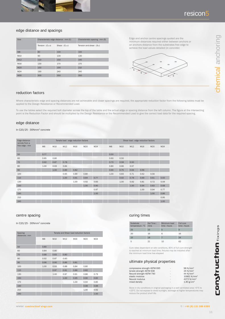
Size Characteristic edge distance : mm (C) Characteristic spacing : mm (S)
Tension : (Ccr,N) Shear : (Ccr,V) Tension and shear : (Scr)
M8 80 100 100
M10 90 130 130
M12 110 150 140
M16 130 170 170
M20 150 190 210
M24 190 240 240
M30 300 350 350
edge distance and spacings
Edge and anchor centre spacings quoted are the minimum distances required either between anchors or an anchors distance from the substrates free edge to achieve the load values detailed (in concrete)
reduction factors
Where characteristic edge and spacing distances are not achievable and closer spacings are required, the appropriate reduction factor from the following tables must be applied to the Design Resistance or Recommended Load.
To use the tables select the required bolt diameter across the top of the table and the actual edge or spacing distance from the left column. The fi gure at the intersecting point is the Reduction Factor and should be multiplied by the Design Resistance or the Recommended Load to give the correct load data for the required spacing.
edge distance
Edge distance - remote from a free edge : mm
Tensile load : edge reduction factors Shear load : edge reduction factors
M8 M10 M12 M16 M20 M24 M8 M10 M12 M16 M20 M24
50 0.77 0.50
60 0.85 0.80 0.60 0.50
70 0.92 0.87 0.78 0.70 0.58 0.50
80 1.00 0.93 0.84 0.80 0.66 0.57
90 1.00 0.89 0.82 0.90 0.75 0.64 0.56
100 0.95 0.86 0.80 1.00 0.83 0.71 0.62 0.56
110 1.00 0.91 0.84 0.77 0.92 0.78 0.69 0.61 0.50
130 1.00 0.92 0.83 1.00 0.92 0.81 0.72 0.59
150 1.00 0.90 1.00 0.94 0.83 0.68
170 0.97 1.00 0.94 0.77
190 1.00 1.00 0.86
210 0.95
240 1.00
Spacing distances : mm
Tensile and Shear load reduction factors
M8 M10 M12 M16 M20 M24
50 0.80
60 0.84 0.80
70 0.88 0.83 0.80
80 0.92 0.87 0.83
90 0.96 0.90 0.86 0.81
100 1.00 0.93 0.88 0.84 0.80
110 0.97 0.91 0.86 0.82
130 1.00 0.97 0.91 0.86 0.79
150 1.00 0.95 0.90 0.82
170 1.00 0.94 0.85
190 0.98 0.88
210 1.00 0.92
240 1.00
Substratetemperature : 0C
Gel Time : mins
Minimum load time : hours
Full cure time : hours
25 15 5 9
20 16 6 16
15 18 7 34
5 21 10 62
Cure rates dependant on site conditions, 80% of full cure strength is reached at minimum load time, fi xtures may be installed after the minimum load time has elapsed
curing timescentre spacing
compressive strength ASTM 695 - 98 N/mm2
tensile strength ASTM 638 - 26 N/mm2
fl exural strength ASTM 790 - 44 N/mm2
elastic modulus - 10961 N/mm2
fl exural modulus - 4272 N/mm2
mixed density - 1.40 g/cm3
ultimate physical properties
Store in dry conditions in original packaging in a well ventilated area +50C to +250C. Do not expose to direct sunlight, storeage at higher temperatures may reduce the product shelf life.
In C20/25 - 30Nmm2 concrete
In C20/25 - 30Nmm2 concrete
www: constructionf xings.com
16
chem
ical
anc
horin
g
t : +44 (0) 121 506 6300
resicon5
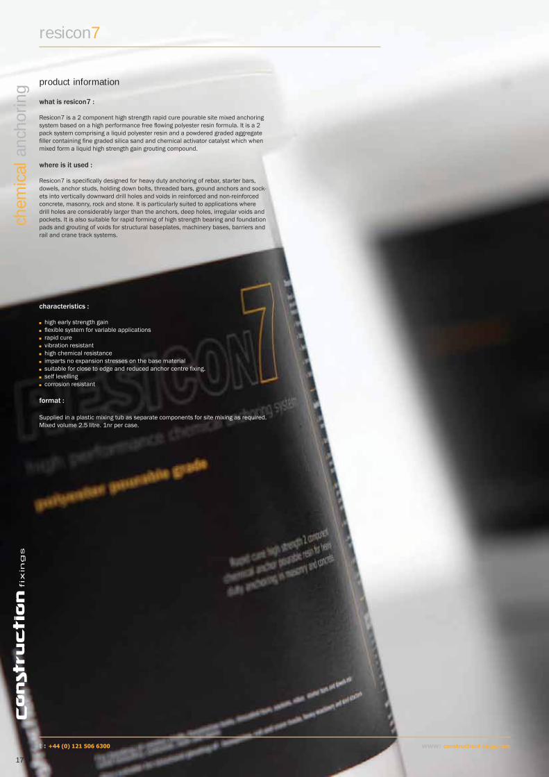
resicon7
characteristics :
high early strength gain fl exible system for variable applications rapid cure vibration resistant high chemical resistance imparts no expansion stresses on the base material suitable for close to edge and reduced anchor centre fi xing. self levelling corrosion resistant
format :
Supplied in a plastic mixing tub as separate components for site mixing as required.Mixed volume 2.5 litre. 1nr per case.
product information
17
www: constructionf xings.com
chem
ical
anc
horin
g
what is resicon7 :
Resicon7 is a 2 component high strength rapid cure pourable site mixed anchoring system based on a high performance free fl owing polyester resin formula. It is a 2 pack system comprising a liquid polyester resin and a powdered graded aggregate fi ller containing fi ne graded silica sand and chemical activator catalyst which when mixed form a liquid high strength gain grouting compound.
where is it used :
Resicon7 is specifi cally designed for heavy duty anchoring of rebar, starter bars, dowels, anchor studs, holding down bolts, threaded bars, ground anchors and sock-ets into vertically downward drill holes and voids in reinforced and non-reinforced concrete, masonry, rock and stone. It is particularly suited to applications where drill holes are considerably larger than the anchors, deep holes, irregular voids and pockets. It is also suitable for rapid forming of high strength bearing and foundation pads and grouting of voids for structural baseplates, machinery bases, barriers and rail and crane track systems.
t : +44 (0) 121 506 6300

installation :
Drill hole to correct diameter and depth, diamond cored drillholes should be roughened prior to injection Clean drillhole thoroughly using wirebrush and remove all dust using a blow out pump or airline Ideally for optimal performance, mix a full pack of resin and the fi ller component in one operation adding the fi ller slowly in the supplied tub either manually or
mechanically using a resicon mixer paddle and slow speed drill. On fi nal addition of the powder continue to mix for a further 2 minutes to a smooth even consistency. If mixing part volumes a 3 : 2 ratio of fi ller to resin should be used Pour in the prepared drillhole or void until 1/3 to 1/2 full (dependant on application) ensuring all air pockets are removed on fi lling Insert clean fi xing with a rotating motion until resin can be seen at the mouth of the hole, remove any excess immediately Leave undisturbed until cured and then attach fi xture and torque to required setting Clean all tooling using a suitable solvent cleaner before gel times have elapsed.
For baseplate grouting and void fi lling, mix as above and simply pour into the void until the required level is reached, all contact surfaces should be dry, dust free andany oil, grease or fl aking rust should be thoroughly removed.
ordering information
product code description size
ANC469 resicon7 polyester resin anchor tub 2.5lANC470 resicon7 mixer paddle
Substratetemperature : 0C
Gel Time : mins
Full cure time : hours
20 40 3
15 60 5
10 100 7
5 160 9
Cure rates for guidance only and are dependant on site conditions.
curing times
compressive strength ASTM 695 - >118 N/mm2
tensile strength ASTM 638 - 16 N/mm2
fl exural strength ASTM 790 - 39 N/mm2
elastic modulus - 8970 N/mm2
mixed density - 1.80 g/cm3
ultimate physical properties
Load data based on tested anchors in accordance with BS 5080 Part 1.
To calculate recommended loads an appropriate safety factor should be considered using either the global or partial safety factor methods.
In 63Nmm2 concrete test blocks using standard embedment depths and 5.8Gr steel anchor studs in clean blown and brushed drill holes.
performance data
Anchor dia : mm (d)
Standard embedment : mm (bo)
Hole diameter concrete : mm (do)
Substratethickness min : mm (hmin)
No of fi xings per tub :(approx)
Ultimate load (pullout) : Kn
tension (x)
Characteristic edge distance : mm (C)
Characteristic spacing : mm (S)
M8 80 10 110 528 22.30 100.00 200.00
M10 90 12 120 327 23.00 112.50 225.00
M12 110 14 140 196 40.00 137.50 275.00
M16 125 18 165 104 64.00 156.25 312.50
M20 170 24 220 34 65.00 212.50 425.00
M24 210 28 270 26 77.18 262.50 525.00
-
2
15
12
9
6
3
100 200 300 400
Load :tonnes
Embedment depth : mm
Typical attained pullout failure loads for deformed and threaded bars to 500N/mm2 in 30N/mm2 concrete
www: constructionf xings.com
18
chem
ical
anc
horin
g
t : +44 (0) 121 506 6300
resicon7

resicon si
19
www: constructionf xings.com
chem
ical
anc
horin
g
t : +44 (0) 121 506 6300

what is Resicon SI :
Resicon SI is a high performance rapid cure spin-in chemical anchor system based on optimum measured proportions of high strength epoxy acrylate resin, chemical activator and quartz aggregate sealed in a glass capsule. It is a fast install, simple to use system requiring no special tools and provides high strength stress free anchoring in concrete and solid masonry.
The system operates by spinning a chisel ended anchor stud using the required drive adaptor through the capsule using a rotary hammer drill which crushes and mixes the contents in the drillhole and initiates the curing process, the stud is left in position to fully cure and form a high strength bond which is stronger than the base material. Capsule sizes are drillhole specifi c from M8 to M30 diameters. The system can be used with longer than standard threaded bars combined with multiple down hole capsules, studs should be cut chisel ended and separate drive adapters are available for connection to a drilling machine.
where is it used :
The system is designed for static and dynamic heavy duty anchoring of anchor studs into vertical and horizontal drill holes in reinforced and non-reinforced concrete, solid masonry, rock and stone. Primarily used where anchor consistency is required and injection resin use would be prohibitive or inconvenient. Due to the viscous nature resicon si is not suitable for overhead installations or perforated and hollow substrates.
characteristics :
• high strength• suitable for low edge and centre spacing • consistent load behaviour• suitable for static and dynamic loading• fast and simple to install• rapid cure• vibration resistant• imparts no expansion stresses on the base material• useable in wet drillholes (requires longer cure time)• drillhole cleanliness not as critical as injection systems.
format :
Individually capsuled, due to the fragile nature of these products, for shipping purposes they are sold only in full box quantities.
ordering information
product code description size : mm box qty ANC449 resicon si capsule 8 x 80 10ANC450 resicon si capsule 10 x 80 10ANC451 resicon si capsule 12 x 95 10ANC452 resicon si capsule 16 x 95 10ANC453 resicon si capsule 20 x 175 6ANC454 resicon si capsule 24 x 210 6ANC455 resicon si capsule 30 x 265 6
product information
resicon si
installation :
1. Drill hole to correct diameter and depth, diamond cored drillholes should be roughened prior to installation2. Clean drillhole thoroughly using wirebrush and remove all dust using a blow out pump or airline3. Place the capsule in the drillhole ensuring fi tting is below the surface4. Attach the driver to the anchor stud, fi t to drill and drive through the capsule until the stud reaches the base of the hole or the depth marker on the stud is reached. 5. Detach the drive tool and leave stud undisturbed until cured and then attach fi xture and torque to required setting
M1
2
www: constructionf xings.com
20
chem
ical
anc
horin
g
drive setting tools
t : +44 (0) 1253 886677
RE
SIC
ON
si

capsule and stud data
technical information
Capsule diameter : mm (d)
Capsulelength : mm (l)
Hole diameter concrete : mm (do)
Rec min drill depth concrete :mm (bo)
Stud diameter : mm (d)
Standard stud length : mm (l)
Recommended torque : Nm (Tinst)
8 80 10 90 8 110 11
10 80 12 90 10 130 22
12 95 14 110 12 160 38
16 95 18 125 16 190 95
20 175 24 190 20 260 150
24 210 28 230 24 300 200
30 265 35 290 30 380 320
Size : mm Characteristic resistance : kN Design resistance : kN Recommended load kN
Tension : (NRk) Shear : (VRk) Tension : (NRd) Shear : (VRd) Tension : (Nrec) Shear : (Vrec)
8 15.40 9.90 8.30 7.90 5.90 5.70
10 23.80 15.70 11.30 12.60 8.10 9.00
12 35.10 22.90 15.90 18.30 11.40 13.10
16 64.40 42.50 28.00 34.00 20.00 24.30
20 103.90 66.80 43.30 53.40 30.90 38.20
24 138.30 95.70 55.30 76.60 39.50 54.70
30 213.90 152.50 85.50 122.00 61.10 87.10
performance data
All load data calculated using the Partial Safety Factor concept and to Eurocode 1 standard. For engineers preferring to use the Global Safety Factor approach the Characteristic Resistance loads are 95% of the Ultimate load values and Recommended loads remain constant for both methods.
Size Characteristic edge distance : mm (C) Characteristic spacing : mm (S)
Tension : (Ccr,N) Shear : (Ccr,V) Tension and shear : (Scr)
M8 100 130 130
M10 130 150 150
M12 150 170 170
M16 170 190 190
M20 220 220 220
M24 260 260 260
M30 340 340 340
edge distance and spacings
Edge and anchor centre spacings quoted are the minimum distances required either between anchors or an anchors distance from the substrates free edge to achieve the load values detailed (in concrete)
resicon si
In C20/25 - 30Nmm2 concrete using standard embedment depths and 5.8Gr steel anchor studs in clean blown and brushed drill holes.
In C20/25 - 30Nmm2 concrete
21
www: constructionf xings.com
chem
ical
anc
horin
g
t : +44 (0) 121 506 6300

Edge distance - remote from a free edge : mm
Tensile load : edge reduction factors Shear load : edge reduction factors
M8 M10 M12 M16 M20 M24 M30 M8 M10 M12 M16 M20 M24 M30
60 0.76 0.50
70 0.82 0.75 0.58 0.50
80 0.88 0.80 0.74 0.66 0.57 0.50
90 0.94 0.85 0.78 0.75 0.64 0.56
100 1.00 0.90 0.83 0.77 0.83 0.71 0.62 0.52
110 0.95 0.87 0.81 0.92 0.78 0.69 0.58 0.50
130 1.00 0.96 0.89 0.77 0.76 1.00 0.93 0.81 0.68 0.59 0.50
150 1.00 0.96 0.83 0.76 1.00 0.94 0.79 0.68 0.57
170 1.00 0.88 0.81 1.00 0.89 0.77 0.65 0.50
190 0.94 0.86 0.75 1.00 0.86 0.73 0.58
220 1.00 0.93 0.80 1.00 0.85 0.65
260 1.00 0.88 1.00 0.76
300 0.92 0.88
340 1.00 1.00
Spacing distances : mm
Tensile and Shear load reduction factors
M8 M10 M12 M16 M20 M24 M30
60 0.80
70 0.83 0.80
80 0.87 0.83 0.80
90 0.90 0.86 0.83
100 0.93 0.89 0.85 0.81
110 0.97 0.91 0.87 0.83 0.80
130 1.00 0.97 0.92 0.87 0.84 0.80
150 1.00 0.97 0.92 0.87 0.83
170 1.00 0.96 0.91 0.86 0.80
190 1.00 0.95 0.89 0.82
220 1.00 0.94 0.85
260 1.00 0.90
300 0.95
340 1.00
reduction factors
Where characteristic edge and spacing distances are not achievable and closer spacings are required, the appropriate reduction factor from the following tables must be applied to the Design Resistance or Recommended Load.
To use the tables select the required bolt diameter across the top of the table and the actual edge or spacing distance from the left column. The fi gure at the intersecting point is the Reduction Factor and should be multiplied by the Design Resistance or the Recommended Load to give the correct load data for the required spacing.
edge distance
centre spacing
In C20/25 - 30Nmm2 concrete
In C20/25 - 30Nmm2 concrete
Substratetemperature : 0C
Cure time dry : hours
Cure time wet : hours
20+ 0.5 1
11-20 1 2
6-10 3 6
1-5 6 12
-5-0 15 30
Cure rates for guidance only and are dependant on site conditions.
curing times
www: constructionf xings.com
22
chem
ical
anc
horin
g
t : +44 (0) 121 506 6300
resicon si

resicon fi xings
23
www: constructionf xings.com
chem
ical
anc
horin
g
t : +44 (0) 121 506 6300
resicon fi xings
Description :
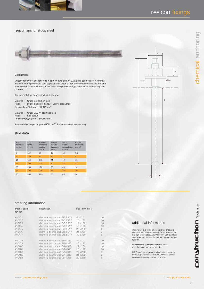
Chisel ended steel anchor studs in carbon steel and A4-316 grade stainless steel for maxi-mum corrosion protection, both supplied with external hex drive complete with hex nut and plain washer for use with any of our injection systems and glass capsules in masonry and concrete.
1nr external drive adapter included per box.
Material : Grade 5.8 carbon steelFinish : Bright zinc plated and/or yellow passivatedTensile strength (nom) : 500N/mm2
Material : Grade 316-A4 stainless steelFinish : Self colourTensile strength (nom) : 800N/mm2
Also available in special grade HCR 1.4529 stainless steel to order only.
resicon anchor studs steel
ordering information
product code description size : mm (d x l) box qty ANC471 chemical anchor stud Gr5.8 ZYP 8 x 110 10ANC472 chemical anchor stud Gr5.8 ZYP 10 x 130 10ANC473 chemical anchor stud Gr5.8 ZYP 12 x 160 10ANC474 chemical anchor stud Gr5.8 ZYP 16 x 190 10ANC475 chemical anchor stud Gr5.8 ZYP 20 x 260 6ANC476 chemical anchor stud Gr5.8 ZYP 24 x 300 6ANC477 chemical anchor stud Gr5.8 ZYP 30 x 360 6
ANC478 chemical anchor stud GrA4-316 8 x 110 10ANC479 chemical anchor stud GrA4-316 10 x 130 10ANC480 chemical anchor stud GrA4-316 12 x 160 10ANC481 chemical anchor stud GrA4-316 16 x 190 10ANC482 chemical anchor stud GrA4-316 20 x 260 6ANC483 chemical anchor stud GrA4-316 24 x 300 6ANC484 chemical anchor stud GrA4-316 30 x 360 6
d
b
c
f
e
l
stud data
Stud diameter : mm (d)
Stud length : mm (l)
Effective anchoring depth : mm (b)
Washer outside diameter : mm (c)
Hex nut width across fl ats : mm (e)
Hex nut thickness : mm (d)
8 110 80 16 13 6.5
10 130 90 20 17 8
12 160 110 24 19 10
16 190 125 30 24 13
20 260 170 37 30 16
24 300 210 44 36 19
30 380 280 56 46 24
Also available, a comprehensive range of square cut threaded bars from M4 to M64 in mild steel, Gr 8.8 high tensile steel, A2-304 and A4-316 stainless steel in various fi nishes for use with all our injection systems.
Non standard chisel ended anchor studs manufactured and plated to order.
NB. Square cut bars and studs require a screw on drive adaptor when used with resicon si capsules. Available separately in sizes up to M30.
additional information
www: constructionf xings.com
24
chem
ical
anc
horin
g
t : +44 (0) 121 506 6300

Description :
A comprehensive range of square cut threaded bars from M4 to M64 in mild steel, high tensile steel and stainless steel in various fi nishes for use with all our injection and pourable resin systems. Applications include general bonding in masonry and concrete where standard resicon stud lengths are unsuitable, bridging cavities and bonding into mortar joints for crack repair. Corresponding Gr 8 hex nuts and washers also available.
Threaded bars ideally should be cut chisel ended or slash cut to 450 to aid insertion without forming air pockets in the injected resin. To prevent potential unscrewing of bars once bonded we recommend threads also be deformed and disrupted prior to installation.
Materials : Grade 4.6 carbon steel : Grade 8.8 high tensile steel : Grade A4-316 stainless steel
Finishes : Gr 4.6 & 8.8 bright zinc plate : A4-316 self colour : hot dipped galvanised available to order.
Tensile strength (nom) : Gr 4.6 - 400N/mm2 : Gr 8.8 - 800N/mm2 : Gr 316 - 800N/mm2
resicon threaded bars
ordering information
product code description size : d x l
THB021 threaded bar Gr 4.6 BZP M5 x 1m THB022 threaded bar Gr 4.6 BZP M6 x 1m THB023 threaded bar Gr 4.6 BZP M8 x 1m THB024 threaded bar Gr 4.6 BZP M10 x 1m THB025 threaded bar Gr 4.6 BZP M12 x 1m THB027 threaded bar Gr 4.6 BZP M16 x 1m THB028 threaded bar Gr 4.6 BZP M20 x 1m THB029 threaded bar Gr 4.6 BZP M24 x 1m THB030 threaded bar Gr 4.6 BZP M27 x 1m THB031 threaded bar Gr 4.6 BZP M30 x 1m
THB099 threaded bar Gr 8.8 BZP M5 x 1m THB100 threaded bar Gr 8.8 BZP M6 x 1m THB101 threaded bar Gr 8.8 BZP M8 x 1m THB102 threaded bar Gr 8.8 BZP M10 x 1m THB103 threaded bar Gr 8.8 BZP M12 x 1m THB105 threaded bar Gr 8.8 BZP M16 x 1m THB107 threaded bar Gr 8.8 BZP M20 x 1m THB109 threaded bar Gr 8.8 BZP M24 x 1m THB110 threaded bar Gr 8.8 BZP M27 x 1m THB111 threaded bar Gr 8.8 BZP M30 x 1m THB112 threaded bar Gr 8.8 BZP M33 x 1m THB113 threaded bar Gr 8.8 BZP M36 x 1m THB114 threaded bar Gr 8.8 BZP M39 x 1m THB115 threaded bar Gr 8.8 BZP M42 x 1m THB116 threaded bar Gr 8.8 BZP M45 x 1m THB117 threaded bar Gr 8.8 BZP M48 x 1m THB118 threaded bar Gr 8.8 BZP M52 x 1m
SST488A4 threaded bar Gr 316-A4 M5 x 1m SST489A4 threaded bar Gr 316-A4 M6 x 1m SST490A4 threaded bar Gr 316-A4 M8 x 1m SST491A4 threaded bar Gr 316-A4 M10 x 1m SST492A4 threaded bar Gr 316-A4 M12 x 1m SST494A4 threaded bar Gr 316-A4 M16 x 1m SST496A4 threaded bar Gr 316-A4 M20 x 1m SST498A4 threaded bar Gr 316-A4 M24 x 1m SST499A4 threaded bar Gr 316-A4 M27 x 1m SST500A4 threaded bar Gr 316-A4 M30 x 1m SST501A4 threaded bar Gr 316-A4 M33 x 1m SST502A4 threaded bar Gr 316-A4 M36 x 1m SST1753A4 threaded bar Gr 316-A4 M39 x 1m SST1754A4 threaded bar Gr 316-A4 M42 x 1m SST1755A4 threaded bar Gr 316-A4 M45 x 1m SST1756A4 threaded bar Gr 316-A4 M48 x 1m SST1757A4 threaded bar Gr 316-A4 M52 x 1m
d
l
resicon fi xings
3m lengths and special sizes available on request
25
www: constructionf xings.com
chem
ical
anc
horin
g
t : +44 (0) 121 506 6300

resicon fi xings
Description :
Forged high strength ring nuts for use with resicon anchor studs and threaded bars to provide eye type anchorages for temporary or permanent works and applications requiring removable fi xing points. Not designed for use in lifting applications or with fall arrest systems, if in any doubt contact our technical department for guidance.
Material : Grade 5.8 carbon steel : Grade A4-316 stainless steelFinish : Gr 5.8 bright zinc plated and yellow passivated : A4-316 self colourTensile strength (nom) : Gr 5.8 - 500N/mm2 : Gr A4-316 - 800N/mm2
resicon ring nut
ordering information
product code description size : mm ANC433 resicon ring nut Gr 5.8 zyp M10 ANC434 resicon ring nut Gr 5.8 zyp M12ANC435 resicon ring nut Gr 5.8 zyp M16ANC436 resicon ring nut Gr 5.8 zyp M20
ANC437 resicon ring nut Gr A4-316 M10ANC438 resicon ring nut Gr A4-316 M12ANC439 resicon ring nut Gr A4-316 M16ANC440 resicon ring nut Gr A4-316 M20
d
b
c
e
a
Description :
Hexagon socket connectors for use with resicon anchor studs and threaded bars to convert male threaded studs to female connection points allowing provision of anchor extensions and stand off applications and assemblies.
Material : Grade 5.8 carbon steel : Grade A4-316 stainless steelFinish : Gr 5.8 bright zinc plated and yellow passivated : A4-316 self colourTensile strength (nom) : Gr 5.8 - 500N/mm2 : Gr A4-316 - 800N/mm2
resicon socket connector
ordering information
product code description size : mm ANC441 resicon hex socket connector Gr 4.6 bzp M10 ANC442 resicon hex socket connector Gr 4.6 bzp M12ANC443 resicon hex socket connector Gr 4.6 bzp M16ANC444 resicon hex socket connector Gr 4.6 bzp M20
ANC445 resicon hex socket connector Gr A4-316 M10ANC446 resicon hex socket connector Gr A4-316 M12ANC447 resicon hex socket connector Gr A4-316 M16ANC448 resicon hex socket connector Gr A4-316 M20
d
h
c
Thread diameter : mm (d)
Ringnut height : mm (c)
Internal diameter : mm (b)
Base height : mm (a)
Ring thickness : mm (e)
M10 44 25 10 10
M12 52 30 11 12
M16 60 35 13 14
M20 70 40 16 16
Thread diameter : mm (d)
Width across fl ats : mm (c)
Height : mm (h)
M10 17 30
M12 19 36
M16 24 48
M20 30 60
www: constructionf xings.com
26
chem
ical
anc
horin
g
Socket data
ring nut data
t : +44 (0) 121 506 6300
Description :
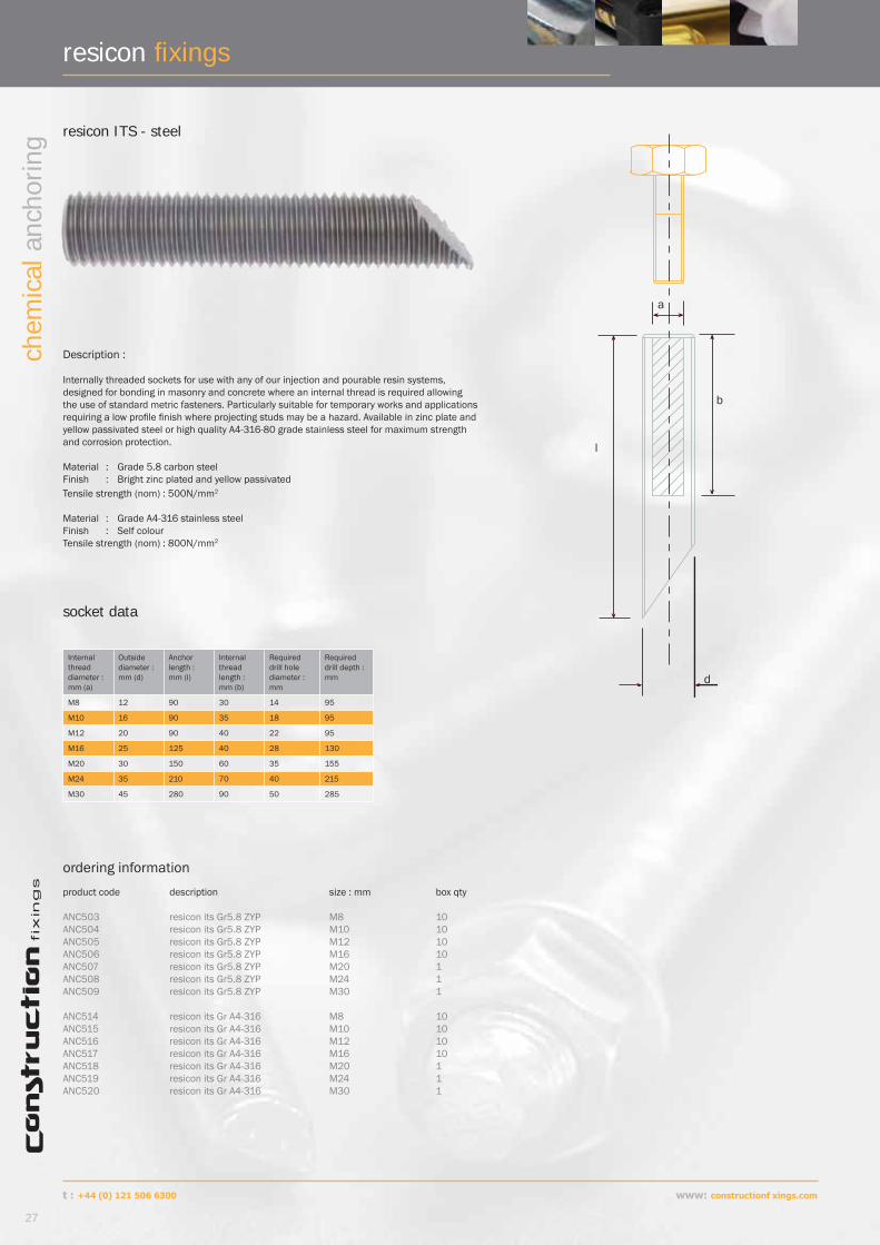
Internally threaded sockets for use with any of our injection and pourable resin systems, designed for bonding in masonry and concrete where an internal thread is required allowing the use of standard metric fasteners. Particularly suitable for temporary works and applications requiring a low profi le fi nish where projecting studs may be a hazard. Available in zinc plate and yellow passivated steel or high quality A4-316-80 grade stainless steel for maximum strength and corrosion protection.
Material : Grade 5.8 carbon steelFinish : Bright zinc plated and yellow passivatedTensile strength (nom) : 500N/mm2
Material : Grade A4-316 stainless steelFinish : Self colourTensile strength (nom) : 800N/mm2
resicon ITS - steel
ordering information
product code description size : mm box qty ANC503 resicon its Gr5.8 ZYP M8 10ANC504 resicon its Gr5.8 ZYP M10 10ANC505 resicon its Gr5.8 ZYP M12 10ANC506 resicon its Gr5.8 ZYP M16 10ANC507 resicon its Gr5.8 ZYP M20 1ANC508 resicon its Gr5.8 ZYP M24 1ANC509 resicon its Gr5.8 ZYP M30 1
ANC514 resicon its Gr A4-316 M8 10ANC515 resicon its Gr A4-316 M10 10ANC516 resicon its Gr A4-316 M12 10ANC517 resicon its Gr A4-316 M16 10ANC518 resicon its Gr A4-316 M20 1ANC519 resicon its Gr A4-316 M24 1ANC520 resicon its Gr A4-316 M30 1
b
a
l
d
socket data
Internal threaddiameter : mm (a)
Outside diameter : mm (d)
Anchor length :mm (l)
Internal thread length : mm (b)
Required drill hole diameter : mm
Required drill depth :mm
M8 12 90 30 14 95
M10 16 90 35 18 95
M12 20 90 40 22 95
M16 25 125 40 28 130
M20 30 150 60 35 155
M24 35 210 70 40 215
M30 45 280 90 50 285
resicon fi xings
27
www: constructionf xings.com
chem
ical
anc
horin
g
t : +44 (0) 121 506 6300

resicon fi xings
www: constructionf xings.com
28
chem
ical
anc
horin
g
Description :
Internally threaded sleeves for use either independently for bonding into solid masonry and concrete or in conjunction with nylon sleeves to provide an internal thread, allowing the use of standard metric fasteners, in perforated and hollow brickwork and blockwork using resicon2 injection resin.
resicon ITSL - steel
ordering information
product description size : mm box qtycode ANC525 resicon itsl Gr5.8 ZYP M6 10ANC526 resicon itsl Gr5.8 ZYP M8 10ANC527 resicon itsl Gr5.8 ZYP M10 10ANC528 resicon itsl Gr5.8 ZYP M12 10
a
l
d
Internal threaddiameter : mm (a)
Outside diameter : mm (d)
Anchor length :mm (l)
Required drill dia without sleeve : mm
Required drill depth without sleeve :mm
Suit sleeve
M6 8 50 10 60 ANC529
M8 12 80 14 90 ANC530
M10 14 80 16 90 ANC530
M12 16 80 18 90 ANC531
Material : Grade 5.8 carbon steelFinish : Bright zinc plated and yellow passivatedTensile strength (nom) : 500N/mm2
socket data
d
l
resicon reinforcement sleeves
Description :
Galvanised steel wire mesh injection sleeves for use with injection resins to provide support and reinforcement for hollow material applications, damaged drill holes, substrates of unknown quality and deep drill holes and cavities.
Supplied in 1 metre lengths for cutting and forming on site.
ordering information
product description size : d x l box qtycode ANC533 resicon reinforcement sleeve 11 x 1000mm 1ANC534 resicon reinforcement sleeve 15 x 1000mm 1ANC535 resicon reinforcement sleeve 20 x 1000mm 1
Size :mm
Drill diameter : mm (d)
Suit studdiameters : mm
11 12 up to M8
15 16 up to M12
20 22 up to M16
sleeve data
t : +44 (0) 121 506 6300

resicon fi xings
Description :
Nylon injection sleeves for use with resicon 2 and 3 injection systems to provide strong anchorages in perforated and hollow brickwork, masonry and concrete. Combine with resicon ITSL for internal threaded anchors in hollow materials, also suitable for use with nylon plugs where a screw type fi xing is required in masonry. Capped for stud centering and overhead applications.
resicon injection sleeves
ordering information
product description size : mm box qtycode ANC529 resicon injection sleeve 10 x 50mm 10ANC530 resicon injection sleeve 14 x 85mm 10ANC531 resicon injection sleeve 14 x 135mm 10ANC532 resicon injection sleeve 18 x 85mm 10
l
d
Code Drill diameter : mm (d)
Sleevelength :mm (l)
Suit studdiameters : mm
Suit ITSL : mm
Suit nylon plug :mm
Screw diameter for plug :mm
ANC529 12 50 up to M8 M6 8 x 40 4-5mm
ANC530 16 85 up to M12 M8 10 x 5012 x 60
5-6mm6-8mm
ANC531 16 135 up to M12 M8
ANC532 20 85 M16 up to M12 14 x 70 8-10mm
29
www: constructionf xings.com
chem
ical
anc
horin
g
sleeve data
resicon nylon plug
ordering information
product description size : mm box qtycode GNF09 resicon nylon plug 8 x 40mm 100GNF10 resicon nylon plug 10 x 50mm 50GNF11 resicon nylon plug 12 x 60mm 25GNF12 resicon nylon plug 14 x 70mm 15
t: +44 (0) 121 506 6300

resicon fi xings
Description :
Nylon retaining and centering cone for use in overhead applications to help retention of the injected resin and to aid stud centering in the drillhole ensuring maximum resin bond for vertical or horizontal fi xings.
resicon retaining cone
ordering information
product description stud size box qtycode ANC536 resicon retaining cone M8 10ANC537 resicon retaining cone M10 10ANC538 resicon retaining cone M12 10ANC539 resicon retaining cone M16 10ANC540 resicon retaining cone M20 10
d
h
c
www: constructionf xings.com
30
chem
ical
anc
horin
g
Studsize :mm
Diameter : mm (c)
Diameter ;mm (d)
Height : mm (h)
M8 9 13 10
M10 11 15 12
M12 13 17 15
M16 17 21 20
M20 21 25 25
cone data
t : +44 (0) 121 506 6300
resicon accessories
31
www: constructionf xings.com
chem
ical
anc
horin
g
t : +44 (0) 121 506 6300
resicon accessories
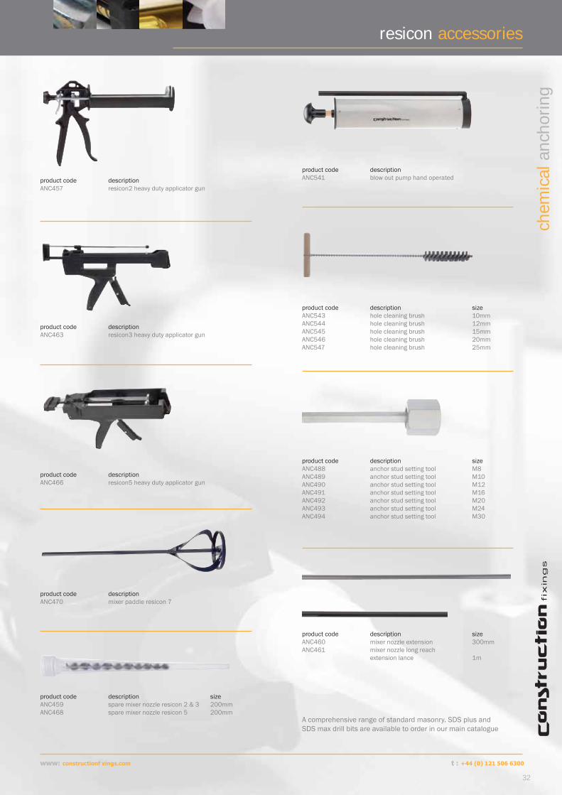
product code description size ANC543 hole cleaning brush 10mmANC544 hole cleaning brush 12mmANC545 hole cleaning brush 15mmANC546 hole cleaning brush 20mmANC547 hole cleaning brush 25mm
product code description size ANC459 spare mixer nozzle resicon 2 & 3 200mm ANC468 spare mixer nozzle resicon 5 200mm
product code description size ANC460 mixer nozzle extension 300mmANC461 mixer nozzle long reach extension lance 1m
product code description ANC470 mixer paddle resicon 7
product code description ANC541 blow out pump hand operated
product code description size ANC488 anchor stud setting tool M8ANC489 anchor stud setting tool M10ANC490 anchor stud setting tool M12ANC491 anchor stud setting tool M16ANC492 anchor stud setting tool M20ANC493 anchor stud setting tool M24ANC494 anchor stud setting tool M30
A comprehensive range of standard masonry. SDS plus and SDS max drill bits are available to order in our main catalogue
www: constructionf xings.com
32
chem
ical
anc
horin
g
product code description ANC457 resicon2 heavy duty applicator gun
product code description ANC463 resicon3 heavy duty applicator gun
product code description ANC466 resicon5 heavy duty applicator gun
t : +44 (0) 121 506 6300

for your notes
33
www: constructionf xings.comt : +44 (0) 121 506 6300 www: constructionf xings.com
chem
ical
anc
horin
g
the resicon® ranget : +44 (0) 1253 886677
f : +44 (0) 1253 893393 e : sales@constructionfi xings.com
technical@constructionfi xings.com
w : www.constructionfi xings.com
t : +44 (0) 121 506 6300f : +44 (0) 121 506 6301e : sales@constructionfi xings.com technical@constructionfi xings.com
w : www.constructionfi xings.com
head offi ce : bracewell avenuepoulton business park poulton le fyldelancashireunited kingdomFY6 8JF