The Renogy Firefly - Solar Power Kits & Equipment for Sale · 2017-02-06 · The Renogy Firefly is...
17
1 The Renogy Firefly 20W Portable Solar System 2775 E. Philadelphia St., Ontario CA 91761 1-800-330-8678
Transcript of The Renogy Firefly - Solar Power Kits & Equipment for Sale · 2017-02-06 · The Renogy Firefly is...
1
The Renogy Firefly
20W Portable Solar System
2775 E. Philadelphia St., Ontario CA 91761
1-800-330-8678
2
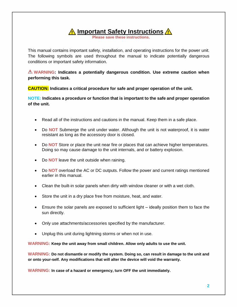
Important Safety Instructions Please save these instructions.
This manual contains important safety, installation, and operating instructions for the power unit.
The following symbols are used throughout the manual to indicate potentially dangerous
conditions or important safety information.
WARNING: Indicates a potentially dangerous condition. Use extreme caution when
performing this task.
CAUTION: Indicates a critical procedure for safe and proper operation of the unit. NOTE: Indicates a procedure or function that is important to the safe and proper operation
of the unit.
Read all of the instructions and cautions in the manual. Keep them in a safe place.
Do NOT Submerge the unit under water. Although the unit is not waterproof, it is water resistant as long as the accessory door is closed.
Do NOT Store or place the unit near fire or places that can achieve higher temperatures. Doing so may cause damage to the unit internals, and or battery explosion.
Do NOT leave the unit outside when raining.
Do NOT overload the AC or DC outputs. Follow the power and current ratings mentioned
earlier in this manual.
Clean the built-in solar panels when dirty with window cleaner or with a wet cloth.
Store the unit in a dry place free from moisture, heat, and water.
Ensure the solar panels are exposed to sufficient light – ideally position them to face the
sun directly.
Only use attachments/accessories specified by the manufacturer.
Unplug this unit during lightning storms or when not in use. WARNING: Keep the unit away from small children. Allow only adults to use the unit.
WARNING: Do not dismantle or modify the system. Doing so, can result in damage to the unit and
or onto your-self. Any modifications that will alter the device will void the warranty.
WARNING: In case of a hazard or emergency, turn OFF the unit immediately.

3
Table of Contents
General Information ...................................................................................................... 4
Identification of Parts .................................................................................................... 5
Installation ..................................................................................................................... 7
Operation ....................................................................................................................... 8
Charging ...................................................................................................................... 12
System Status Troubleshooting ................................................................................ 15
Technical Specifications ............................................................................................ 16
Solar Panels ..........................................................................................................................16
Built-in Electrical Components ...............................................................................................16
Accessories ...........................................................................................................................16
Physical Properties ...............................................................................................................16
Dimensions .................................................................................................................. 17
4
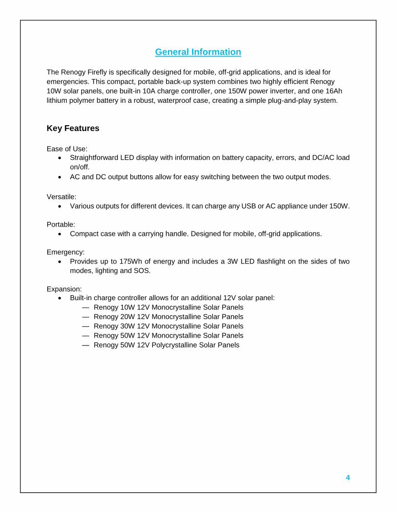
General Information
The Renogy Firefly is specifically designed for mobile, off-grid applications, and is ideal for
emergencies. This compact, portable back-up system combines two highly efficient Renogy
10W solar panels, one built-in 10A charge controller, one 150W power inverter, and one 16Ah
lithium polymer battery in a robust, waterproof case, creating a simple plug-and-play system.
Key Features
Ease of Use:
Straightforward LED display with information on battery capacity, errors, and DC/AC load
on/off.
AC and DC output buttons allow for easy switching between the two output modes.
Versatile:
Various outputs for different devices. It can charge any USB or AC appliance under 150W.
Portable:
Compact case with a carrying handle. Designed for mobile, off-grid applications.
Emergency:
Provides up to 175Wh of energy and includes a 3W LED flashlight on the sides of two
modes, lighting and SOS.
Expansion:
Built-in charge controller allows for an additional 12V solar panel:
— Renogy 10W 12V Monocrystalline Solar Panels
— Renogy 20W 12V Monocrystalline Solar Panels
— Renogy 30W 12V Monocrystalline Solar Panels
— Renogy 50W 12V Monocrystalline Solar Panels
— Renogy 50W 12V Polycrystalline Solar Panels
5
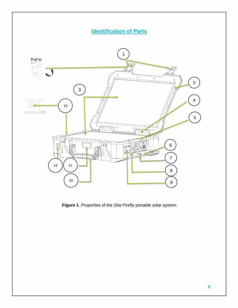
Identification of Parts
Figure 1. Properties of the 20w Firefly portable solar system
Pull to
1
2
3
4
5
6
7
8
9 10
11
13
12
6
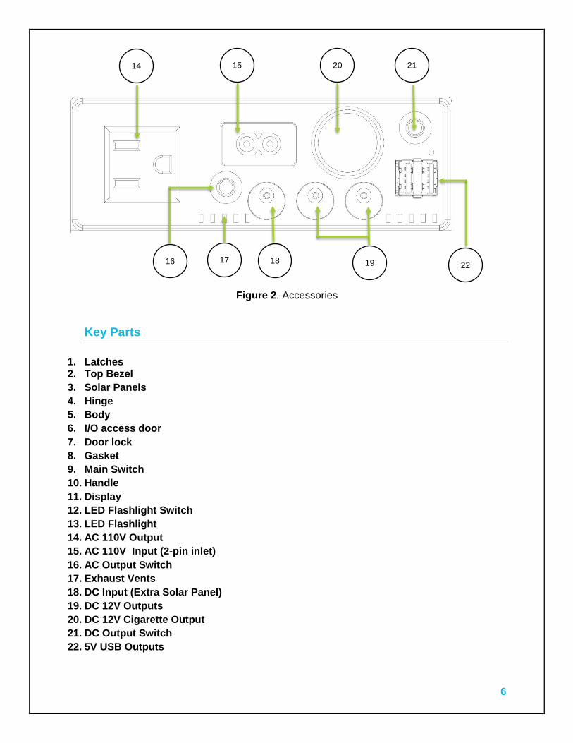
Figure 2. Accessories
Key Parts
1. Latches 2. Top Bezel
3. Solar Panels
4. Hinge
5. Body
6. I/O access door
7. Door lock
8. Gasket
9. Main Switch
10. Handle
11. Display
12. LED Flashlight Switch
13. LED Flashlight
14. AC 110V Output
15. AC 110V Input (2-pin inlet)
16. AC Output Switch
17. Exhaust Vents
18. DC Input (Extra Solar Panel)
19. DC 12V Outputs
20. DC 12V Cigarette Output
21. DC Output Switch
22. 5V USB Outputs
14 15
16 17 18 19
20 21
22
7
Installation
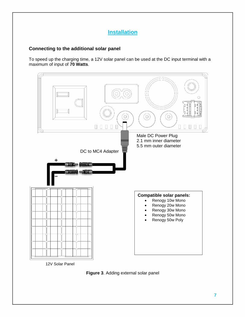
Connecting to the additional solar panel To speed up the charging time, a 12V solar panel can be used at the DC input terminal with a maximum of input of 70 Watts.
Figure 3. Adding external solar panel
Male DC Power Plug 2.1 mm inner diameter 5.5 mm outer diameter
12V Solar Panel
Compatible solar panels: Renogy 10w Mono
Renogy 20w Mono
Renogy 30w Mono
Renogy 50w Mono
Renogy 50w Poly
DC to MC4 Adapter
8
Operation
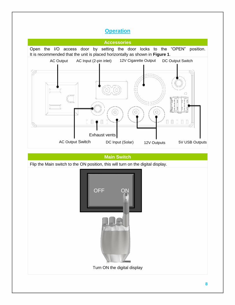
Accessories
Open the I/O access door by setting the door locks to the “OPEN” position.
It is recommended that the unit is placed horizontally as shown in Figure 1.
Main Switch
Flip the Main switch to the ON position, this will turn on the digital display.
Turn ON the digital display
AC Output AC Input (2-pin inlet) 12V Cigarette Output
AC Output Switch
DC Output Switch
5V USB Outputs 12V Outputs DC Input (Solar)
Exhaust vents
OFF ON
9
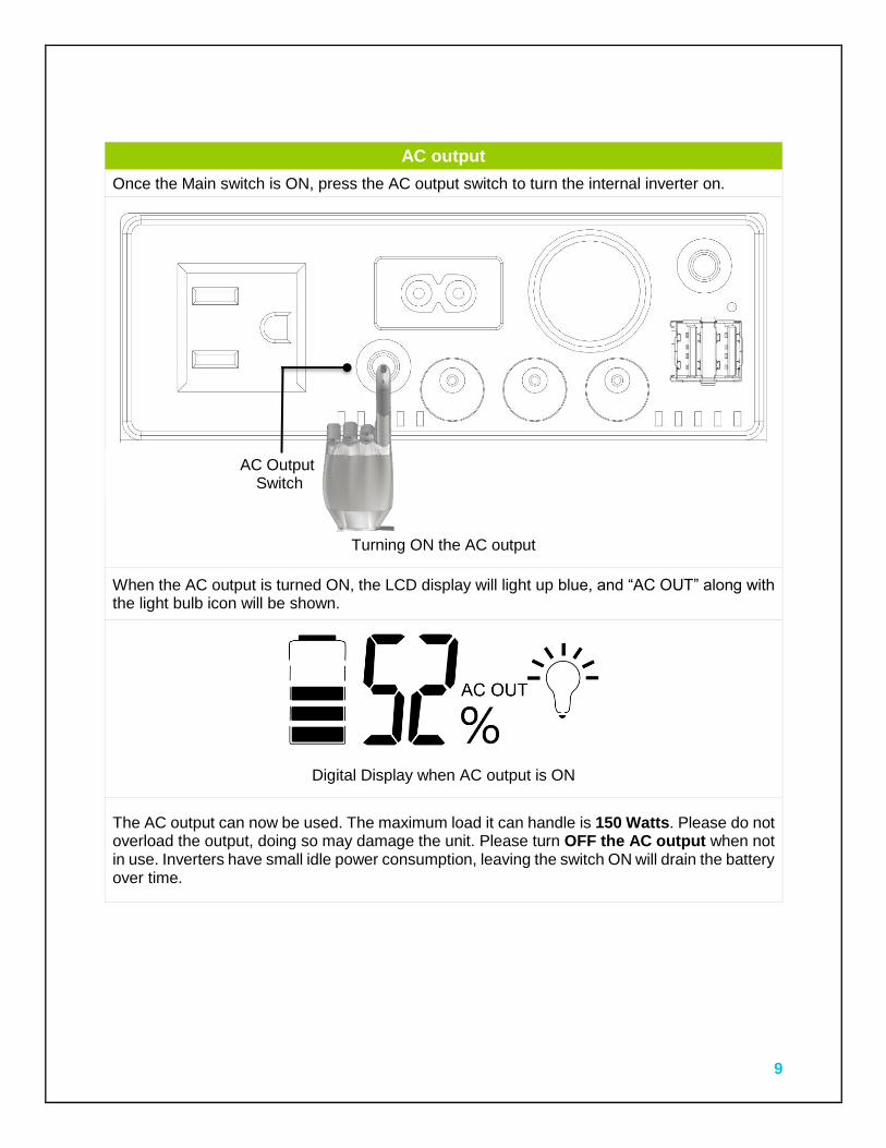
AC output
Once the Main switch is ON, press the AC output switch to turn the internal inverter on.
Turning ON the AC output
When the AC output is turned ON, the LCD display will light up blue, and “AC OUT” along with the light bulb icon will be shown.
Digital Display when AC output is ON
The AC output can now be used. The maximum load it can handle is 150 Watts. Please do not overload the output, doing so may damage the unit. Please turn OFF the AC output when not in use. Inverters have small idle power consumption, leaving the switch ON will drain the battery over time.
AC Output Switch
10
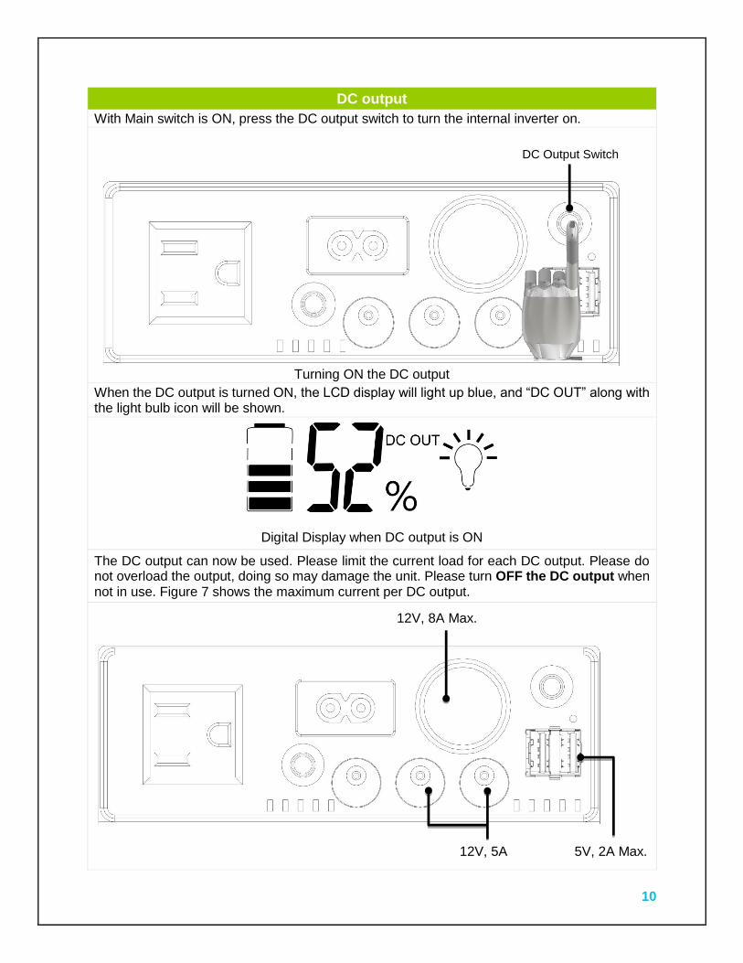
DC output
With Main switch is ON, press the DC output switch to turn the internal inverter on.
Turning ON the DC output
When the DC output is turned ON, the LCD display will light up blue, and “DC OUT” along with the light bulb icon will be shown.
Digital Display when DC output is ON
The DC output can now be used. Please limit the current load for each DC output. Please do not overload the output, doing so may damage the unit. Please turn OFF the DC output when not in use. Figure 7 shows the maximum current per DC output.
DC Output Switch
12V, 8A Max.
5V, 2A Max. 12V, 5A Max.
11
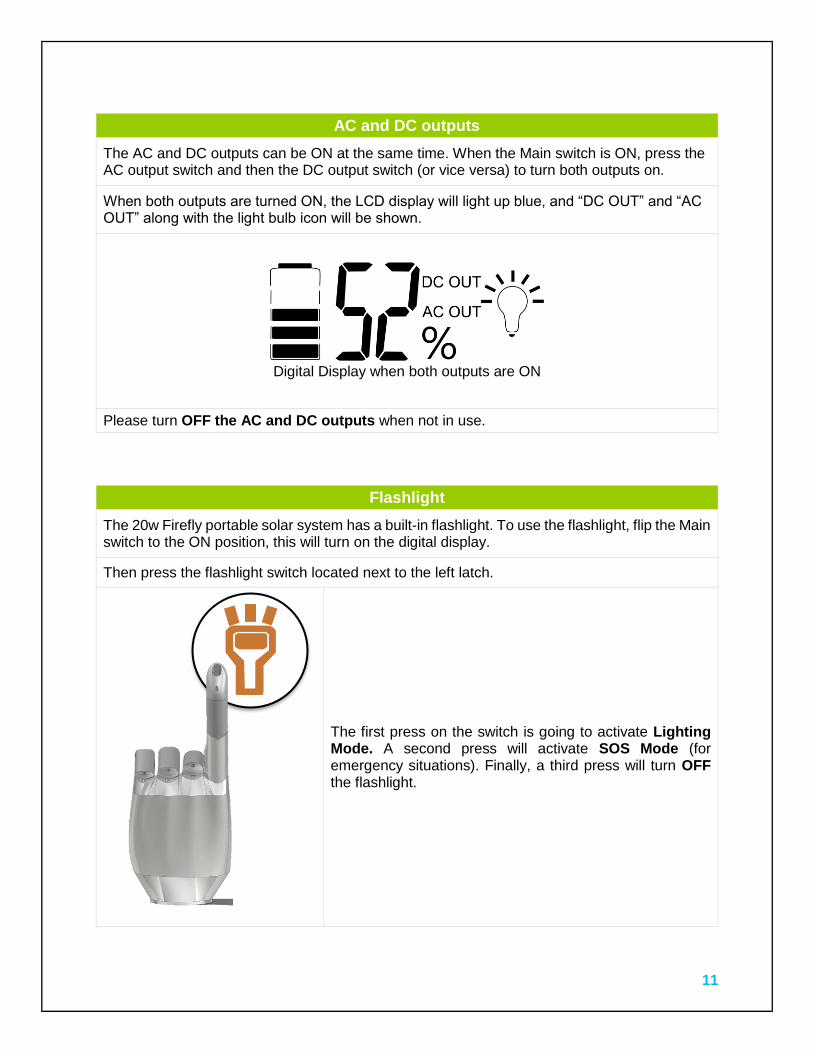
AC and DC outputs
The AC and DC outputs can be ON at the same time. When the Main switch is ON, press the AC output switch and then the DC output switch (or vice versa) to turn both outputs on.
When both outputs are turned ON, the LCD display will light up blue, and “DC OUT” and “AC OUT” along with the light bulb icon will be shown.
Digital Display when both outputs are ON
Please turn OFF the AC and DC outputs when not in use.
Flashlight
The 20w Firefly portable solar system has a built-in flashlight. To use the flashlight, flip the Main switch to the ON position, this will turn on the digital display.
Then press the flashlight switch located next to the left latch.
The first press on the switch is going to activate Lighting Mode. A second press will activate SOS Mode (for emergency situations). Finally, a third press will turn OFF the flashlight.
12
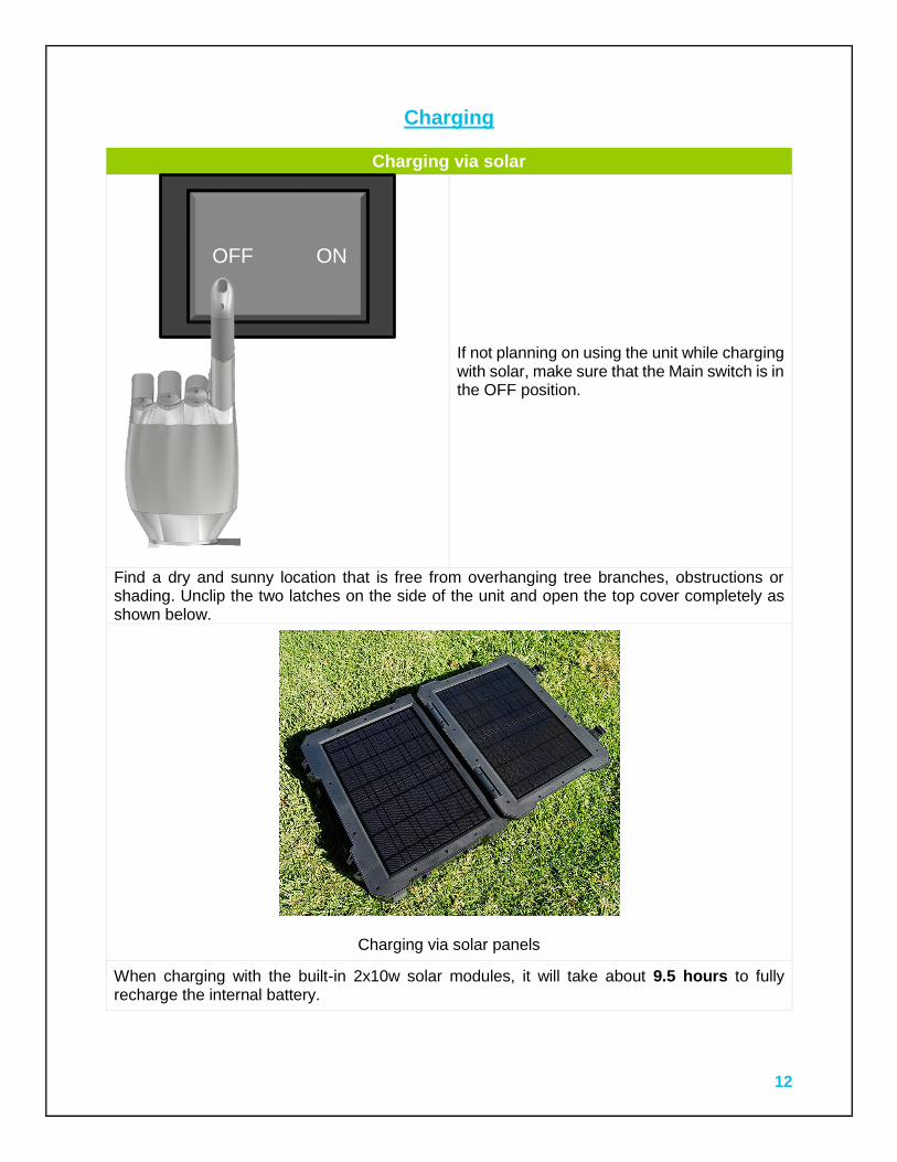
Charging
Charging via solar
If not planning on using the unit while charging with solar, make sure that the Main switch is in the OFF position.
Find a dry and sunny location that is free from overhanging tree branches, obstructions or shading. Unclip the two latches on the side of the unit and open the top cover completely as shown below.
Charging via solar panels
When charging with the built-in 2x10w solar modules, it will take about 9.5 hours to fully recharge the internal battery.
OFF ON
13
Charging with additional solar panels
As shown in Figure 4, an additional 12V solar panel can be used at the DC input terminal to speed up the charging time. The specific charging times with different additional panels are as follows.
Additional Solar Panel Charging Time
10W 6.5 hours
20W 5 hours 30W 4 hours
50W 3 hours
If planning on using the unit while charging with solar, make sure that the Main switch is in the ON position. Then turn ON the desired output. AC and DC outputs can also be used while the unit is being charged by solar however, limit the current output to the values mentioned earlier.
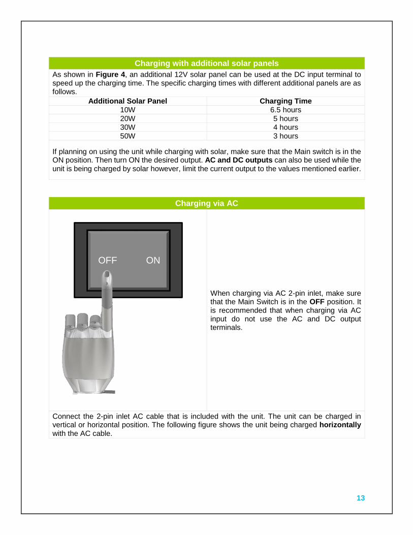
Charging via AC
When charging via AC 2-pin inlet, make sure that the Main Switch is in the OFF position. It is recommended that when charging via AC input do not use the AC and DC output terminals.
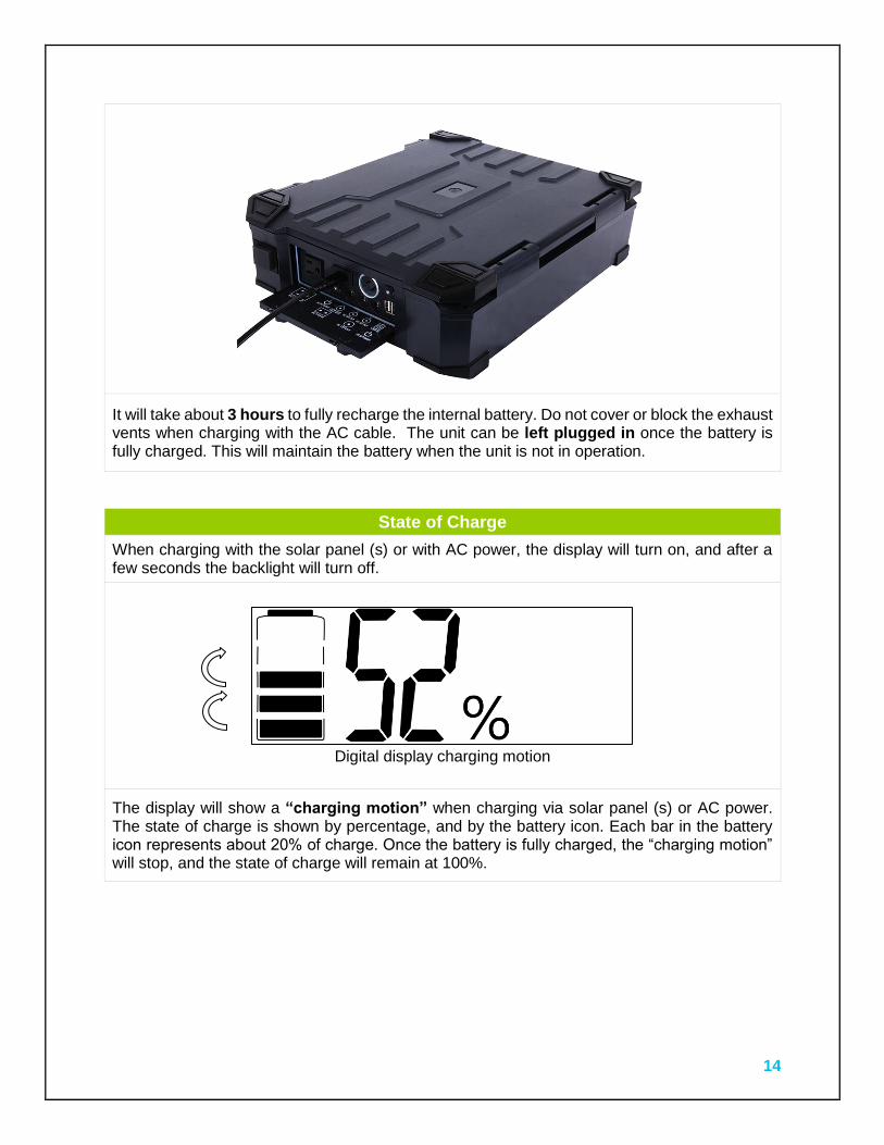
Connect the 2-pin inlet AC cable that is included with the unit. The unit can be charged in vertical or horizontal position. The following figure shows the unit being charged horizontally with the AC cable.
OFF ON
14
It will take about 3 hours to fully recharge the internal battery. Do not cover or block the exhaust vents when charging with the AC cable. The unit can be left plugged in once the battery is fully charged. This will maintain the battery when the unit is not in operation.
State of Charge
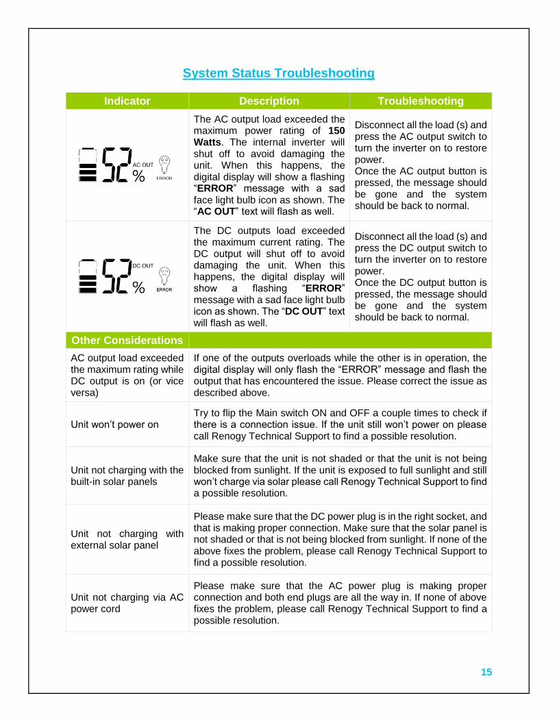
When charging with the solar panel (s) or with AC power, the display will turn on, and after a few seconds the backlight will turn off.
Digital display charging motion
The display will show a “charging motion” when charging via solar panel (s) or AC power. The state of charge is shown by percentage, and by the battery icon. Each bar in the battery icon represents about 20% of charge. Once the battery is fully charged, the “charging motion” will stop, and the state of charge will remain at 100%.
15
System Status Troubleshooting
Indicator Description Troubleshooting
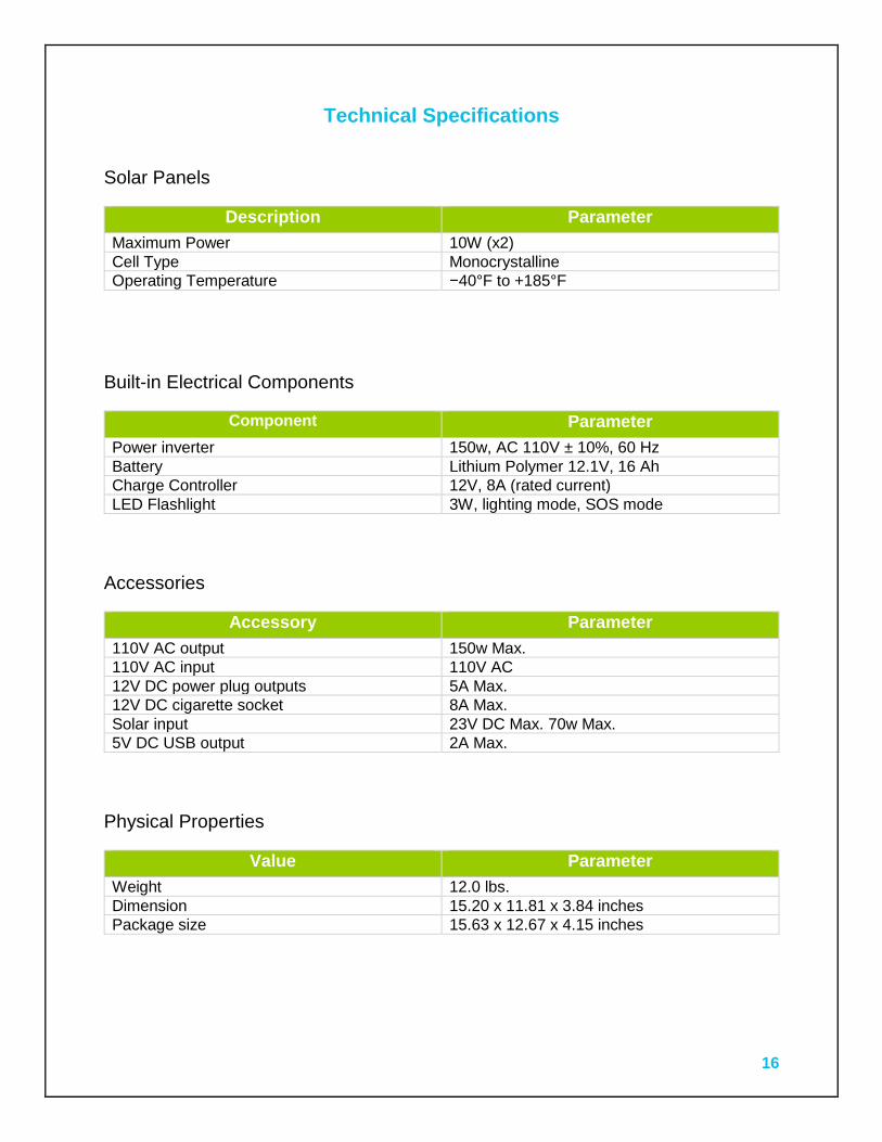
The AC output load exceeded the maximum power rating of 150 Watts. The internal inverter will shut off to avoid damaging the unit. When this happens, the digital display will show a flashing “ERROR” message with a sad face light bulb icon as shown. The “AC OUT” text will flash as well.
Disconnect all the load (s) and press the AC output switch to turn the inverter on to restore power. Once the AC output button is pressed, the message should be gone and the system should be back to normal.
The DC outputs load exceeded the maximum current rating. The DC output will shut off to avoid damaging the unit. When this happens, the digital display will show a flashing “ERROR” message with a sad face light bulb icon as shown. The “DC OUT” text will flash as well.
Disconnect all the load (s) and press the DC output switch to turn the inverter on to restore power. Once the DC output button is pressed, the message should be gone and the system should be back to normal.
Other Considerations
AC output load exceeded the maximum rating while DC output is on (or vice versa)
If one of the outputs overloads while the other is in operation, the digital display will only flash the “ERROR” message and flash the output that has encountered the issue. Please correct the issue as described above.
Unit won’t power on Try to flip the Main switch ON and OFF a couple times to check if there is a connection issue. If the unit still won’t power on please call Renogy Technical Support to find a possible resolution.
Unit not charging with the built-in solar panels
Make sure that the unit is not shaded or that the unit is not being blocked from sunlight. If the unit is exposed to full sunlight and still won’t charge via solar please call Renogy Technical Support to find a possible resolution.
Unit not charging with external solar panel
Please make sure that the DC power plug is in the right socket, and that is making proper connection. Make sure that the solar panel is not shaded or that is not being blocked from sunlight. If none of the above fixes the problem, please call Renogy Technical Support to find a possible resolution.
Unit not charging via AC power cord
Please make sure that the AC power plug is making proper connection and both end plugs are all the way in. If none of above fixes the problem, please call Renogy Technical Support to find a possible resolution.
16
Technical Specifications
Solar Panels
Description Parameter
Maximum Power 10W (x2)
Cell Type Monocrystalline
Operating Temperature −40°F to +185°F
Built-in Electrical Components
Component Parameter
Power inverter 150w, AC 110V ± 10%, 60 Hz
Battery Lithium Polymer 12.1V, 16 Ah
Charge Controller 12V, 8A (rated current)
LED Flashlight 3W, lighting mode, SOS mode
Accessories
Accessory Parameter
110V AC output 150w Max.
110V AC input 110V AC
12V DC power plug outputs 5A Max.
12V DC cigarette socket 8A Max.
Solar input 23V DC Max. 70w Max.
5V DC USB output 2A Max.
Physical Properties
Value Parameter
Weight 12.0 lbs.
Dimension 15.20 x 11.81 x 3.84 inches
Package size 15.63 x 12.67 x 4.15 inches
17
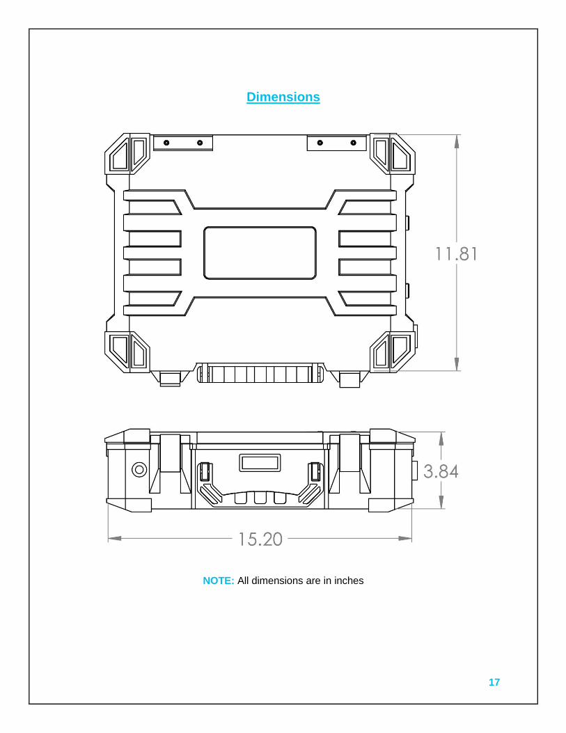
Dimensions
NOTE: All dimensions are in inches