The Relationship Between Geology and Landslide Hazards of ... · the vicinity of Atchison, Kansas,...
16
The Relationship Between Geology and Landslide Hazards of Atchison, Kansas, and Vicinity Gregory C. Ohlmacher Kansas Geological Survey, 1930 Constant Avenue, Lawrence, Kansas 66047 Abstract Landslides along the Missouri and Kansas rivers will affect existing structures and potential development in the Kansas City metropolitan area. A pilot landslide-mapping project was conducted in the vicinity of Atchison, Kansas, to inventory existing landslides and determine the factors that caused them. Landslides are generally controlled by the slope morphology, geology, soils, and moisture conditions. For this study, landslides were divided into recent and older landslides (including earth slides and earth flows) and rock-fall hazards (including rock falls and rock topples). Recent landslides are associated with shale members of the Pennsylvanian Lawrence Formation, Oread Limestone, Kanwaka Shale, and Tecumseh Shale. Limestone layers that occur between these shale members were incorporated into recent and older landslides. Recent landslides occurred on slopes with an average angle of 22 degrees. Recent landslides were also observed in glacial drift, loess, and alluvium. Rock- fall hazards occurred in areas of nearly vertical slopes along streams, river bluffs, highways, and quarries, where limestone members of the Pennsylvanian Oread, Lecompton, and Deer Creek Limestones are exposed. Troublesome rock-fall hazards occurred where weak shale layers are eroding underneath resistant limestone layers. Introduction In 1995, a landslide destroyed two $400,000 homes in Overland Park, Kansas, dramatically underscoring the need for landslide studies in the greater Kansas City metropolitan area. During reconnaissance mapping in 1997, landslides were located along the Missouri River from Kansas City to Wathena, along the Kansas River from Kansas City to Topeka, and along Stranger Creek from the Kansas River to Potter (fig. 1). Based on the reconnaissance and previous damaging landslides in Wyandotte and Johnson counties, a pilot project was initiated to study the landslide hazards of the Kansas City metropolitan area in Kansas. The objectives of the pilot project were to produce a landslide inventory map (Ohlmacher, 2000) and a landslide susceptibility map for a region near the Kansas City metropolitan area. An inventory map shows the locations of landslides and related features, whereas a susceptibility map ranks the degree to which parts of the study area are prone to future landslides, based on the factors that produced past landslides. (A landslide susceptibility map does not provide information on how often landslides occur, as in a landslide hazard map, or the extent of damages and injuries that might be anticipated from a future landslide event, as in a landslide risk map.) A landslide event is defined as one or more landslides occurring during a limited time frame—for example, during and following a severe rainstorm. A landslide susceptibility map requires detailed information on the FIGURE 1. Map of northeast Kansas, showing the location of the study area (green shaded area) and locations mentioned in the text. Stranger Creek Missouri River Atchison Wathena Potter Leavenworth Kansas City Lawrence Topeka BROWN DONIPHAN ATCHISON JACKSON SHAWNEE JEFFERSON JOHNSON DOUGLAS WYAN- DOTTE LEAVEN- WORTH 0 0 10 10 20 20 30 km mi 95 40 39 95 30' 39 30' 94 30' Study Area K a n s a s R i v e r
Transcript of The Relationship Between Geology and Landslide Hazards of ... · the vicinity of Atchison, Kansas,...

Relationship Between Geology and Landslide Hazards of Atchison, Kansas 1
The Relationship Between Geology and Landslide Hazards ofAtchison, Kansas, and Vicinity
Gregory C. OhlmacherKansas Geological Survey, 1930 Constant Avenue, Lawrence, Kansas 66047
AbstractLandslides along the Missouri and Kansas rivers will affect existing structures and potential
development in the Kansas City metropolitan area. A pilot landslide-mapping project was conducted inthe vicinity of Atchison, Kansas, to inventory existing landslides and determine the factors that causedthem. Landslides are generally controlled by the slope morphology, geology, soils, and moistureconditions. For this study, landslides were divided into recent and older landslides (including earthslides and earth flows) and rock-fall hazards (including rock falls and rock topples). Recent landslidesare associated with shale members of the Pennsylvanian Lawrence Formation, Oread Limestone,Kanwaka Shale, and Tecumseh Shale. Limestone layers that occur between these shale members wereincorporated into recent and older landslides. Recent landslides occurred on slopes with an averageangle of 22 degrees. Recent landslides were also observed in glacial drift, loess, and alluvium. Rock-fall hazards occurred in areas of nearly vertical slopes along streams, river bluffs, highways, andquarries, where limestone members of the Pennsylvanian Oread, Lecompton, and Deer CreekLimestones are exposed. Troublesome rock-fall hazards occurred where weak shale layers are erodingunderneath resistant limestone layers.
IntroductionIn 1995, a landslide destroyed two $400,000 homes in
Overland Park, Kansas, dramatically underscoring theneed for landslide studies in the greater Kansas Citymetropolitan area. During reconnaissance mapping in1997, landslides were located along the Missouri Riverfrom Kansas City to Wathena, along the Kansas Riverfrom Kansas City to Topeka, and along Stranger Creekfrom the Kansas River to Potter (fig. 1). Based on thereconnaissance and previous damaging landslides inWyandotte and Johnson counties, a pilot project wasinitiated to study the landslide hazards of the Kansas Citymetropolitan area in Kansas.
The objectives of the pilot project were to produce alandslide inventory map (Ohlmacher, 2000) and alandslide susceptibility map for a region near the KansasCity metropolitan area. An inventory map shows thelocations of landslides and related features, whereas asusceptibility map ranks the degree to which parts of thestudy area are prone to future landslides, based on thefactors that produced past landslides. (A landslidesusceptibility map does not provide information on howoften landslides occur, as in a landslide hazard map, or theextent of damages and injuries that might be anticipatedfrom a future landslide event, as in a landslide risk map.)A landslide event is defined as one or more landslides
occurring during a limited time frame—for example,during and following a severe rainstorm. A landslidesusceptibility map requires detailed information on the
FIGURE 1. Map of northeast Kansas, showing the location of thestudy area (green shaded area) and locations mentioned in thetext.
Stranger
Creek
Missouri
River
Atchison
Wathena
Potter
Leavenworth
Kansas City
Lawrence
Topeka
BROWN
DONIPHAN
ATCHISON
JACKSON
SHAWNEE
JEFFERSON
JOHNSONDOUGLAS
WYAN-DOTTE
LEAVEN-WORTH
0
0 10
10 20
20 30 km
mi
9540
39
95 30'
39 30'
94 30'
Study Area
Kansas River

2 Ohlmacher
factors causing landslides, including slope morphology,geology, and soils. This report presents information on thecausal factors collected as part of the pilot study.
Setting
The area around Atchison, Kansas, was chosen as thestudy area for the pilot project because of its proximity tothe Kansas City metropolitan area and the occurrence oflandslides (fig. 1). Landslides around Atchison wereobserved during the 1997 reconnaissance mapping andwere reported by a former Atchison city engineer (J.Hixon, personal communication, 1997). One of thereported landslides broke a sewer line south of downtown,and another landslide occurred behind a house nearJackson Park. A map showing the location of landslidesand breaks in the sewer line between downtown andJackson Park was produced by the City of Atchison(unpublished data, 1995). The map shows the locations offive sewer breaks that occurred during the last 10 years. Itis not known how many breaks resulted from landslides.
Atchison is presently unaffected, or only marginallyaffected, by the growth of the Kansas City metropolitanarea. Except for some growth in the 1920’s and in the late1990’s, both the city and county have seen a slow, steadydecline in population, and this decline is projected tocontinue in the near future (Helyar, 1999). However, newhomes being constructed in and to the south of Atchisonsuggest that growth may be on the rise.
The study area around Atchison lies within theGlaciated Region physiographic province, whereas Kansas
City straddles the boundary between the Glaciated Regionand the Osage Cuestas. Although this might implygeologic differences between the two areas, the surficialgeology around Atchison and Kansas City is fairly similar.The rocks at the surface in both areas consist of glacialdrift, loess, bedrock, and alluvium, although the KansasCity area has less glacial drift and more bedrock. Thetopography of both Atchison and Kansas City is controlledby the Missouri River and its tributaries. Geologicsimilarities, the potential for population growth, and theproximity to Kansas City made Atchison a suitablelocation for the pilot project.
Physiography
The study area, which includes the entire City ofAtchison and part of Atchison County, was defined as thearea covered by the U.S. Geological Survey Atchison Westand the Atchison East 7-1/2 minute topographic maps(excluding Missouri) (fig. 1). In general, the study areaconsists of an area of gently rolling hills to the west and amore rugged, hilly topography to the east, near theMissouri River. The total relief is about 112 m (370 ft),and the greatest local relief, 73.2 m (240 ft), occurs alongthe bluffs of the Missouri River. The Missouri River andits tributaries—the Independence, White Clay, Brewery,Whiskey, Walnut, and Camp creeks—drain the study area(fig. 2). Steep slopes occur in the bluffs along theMissouri River and its tributaries, where bedrock units ofPennsylvanian age are exposed. The glacial deposits in thewestern half of the study area have relatively gentle slopes.
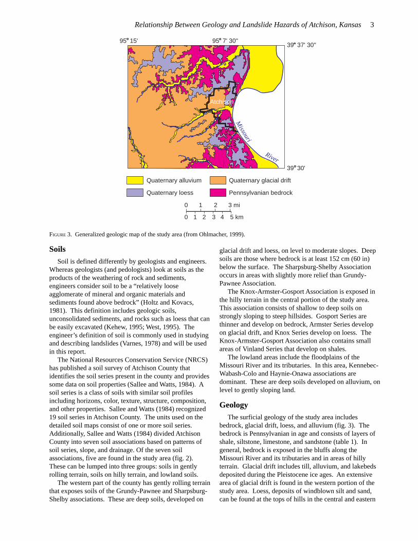
FIGURE 2. Map of the study area showing the soil associations as defined by the National Resources Conservation Service (Sallee andWatts, 1984). Soil associations are regions with similar soil series, slope morphology, and drainage characteristics.
95 15' 95 7' 30''39 37' 30''
39 30'
Atchison
0
0
1
1
2
2
3 mi
3 4 5 km
Grundy-Pawnee Kennebec-Wabash-Colo
Sharpsburg-Shelby Haynie-Onawa
Knox-Armster-Gosport
Independence Creek
White Clay Creek
Creek
Brewery
Whiskey Cre
ek
Walnut Creek
Cam
p Creek
Missour i
River
Relationship Between Geology and Landslide Hazards of Atchison, Kansas 3
SoilsSoil is defined differently by geologists and engineers.
Whereas geologists (and pedologists) look at soils as theproducts of the weathering of rock and sediments,engineers consider soil to be a “relatively looseagglomerate of mineral and organic materials andsediments found above bedrock” (Holtz and Kovacs,1981). This definition includes geologic soils,unconsolidated sediments, and rocks such as loess that canbe easily excavated (Kehew, 1995; West, 1995). Theengineer’s definition of soil is commonly used in studyingand describing landslides (Varnes, 1978) and will be usedin this report.
The National Resources Conservation Service (NRCS)has published a soil survey of Atchison County thatidentifies the soil series present in the county and providessome data on soil properties (Sallee and Watts, 1984). Asoil series is a class of soils with similar soil profilesincluding horizons, color, texture, structure, composition,and other properties. Sallee and Watts (1984) recognized19 soil series in Atchison County. The units used on thedetailed soil maps consist of one or more soil series.Additionally, Sallee and Watts (1984) divided AtchisonCounty into seven soil associations based on patterns ofsoil series, slope, and drainage. Of the seven soilassociations, five are found in the study area (fig. 2).These can be lumped into three groups: soils in gentlyrolling terrain, soils on hilly terrain, and lowland soils.
The western part of the county has gently rolling terrainthat exposes soils of the Grundy-Pawnee and Sharpsburg-Shelby associations. These are deep soils, developed on
glacial drift and loess, on level to moderate slopes. Deepsoils are those where bedrock is at least 152 cm (60 in)below the surface. The Sharpsburg-Shelby Associationoccurs in areas with slightly more relief than Grundy-Pawnee Association.
The Knox-Armster-Gosport Association is exposed inthe hilly terrain in the central portion of the study area.This association consists of shallow to deep soils onstrongly sloping to steep hillsides. Gosport Series arethinner and develop on bedrock, Armster Series developon glacial drift, and Knox Series develop on loess. TheKnox-Armster-Gosport Association also contains smallareas of Vinland Series that develop on shales.
The lowland areas include the floodplains of theMissouri River and its tributaries. In this area, Kennebec-Wabash-Colo and Haynie-Onawa associations aredominant. These are deep soils developed on alluvium, onlevel to gently sloping land.
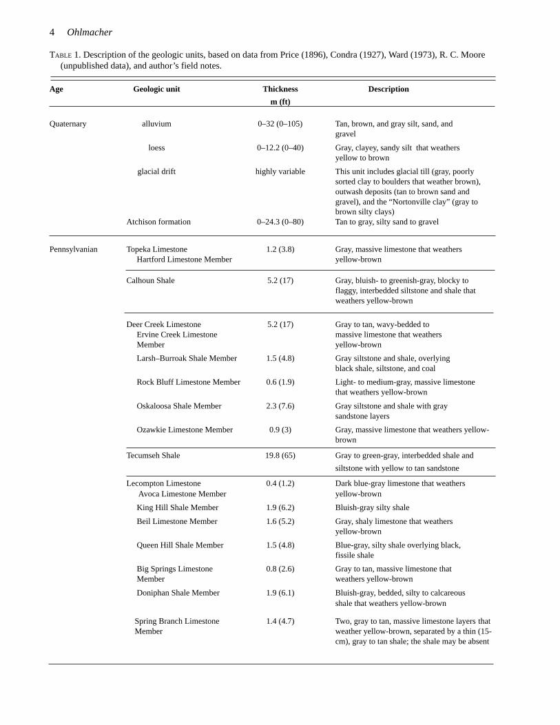
GeologyThe surficial geology of the study area includes
bedrock, glacial drift, loess, and alluvium (fig. 3). Thebedrock is Pennsylvanian in age and consists of layers ofshale, siltstone, limestone, and sandstone (table 1). Ingeneral, bedrock is exposed in the bluffs along theMissouri River and its tributaries and in areas of hillyterrain. Glacial drift includes till, alluvium, and lakebedsdeposited during the Pleistocene ice ages. An extensivearea of glacial drift is found in the western portion of thestudy area. Loess, deposits of windblown silt and sand,can be found at the tops of hills in the central and eastern
FIGURE 3. Generalized geologic map of the study area (from Ohlmacher, 1999).
Quaternary alluvium Quaternary glacial drift
Quaternary loess Pennsylvanian bedrock
Missouri
River
0
0
1
1
2
2
3 mi
3 4 5 km
95 15' 95 7' 30''39 37' 30''
39 30'
Atchison
4 Ohlmacher
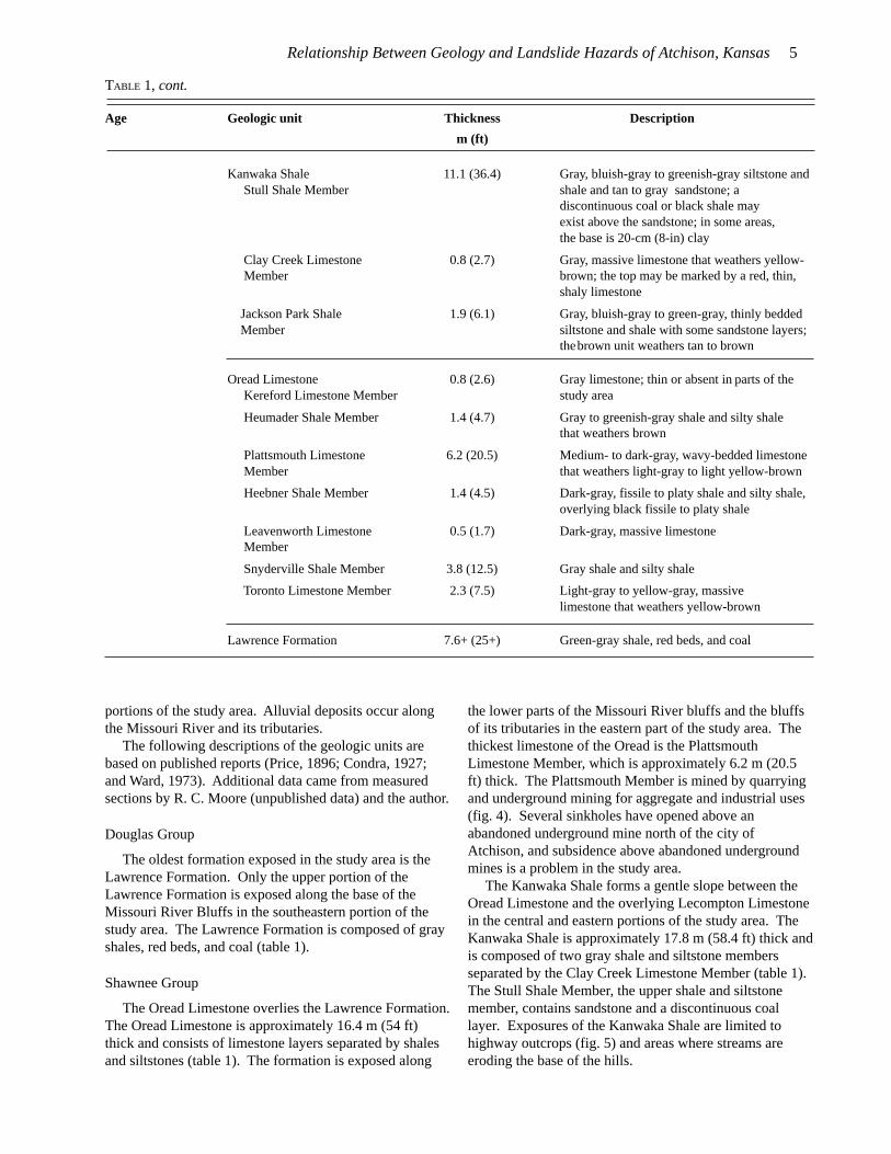
TABLE 1. Description of the geologic units, based on data from Price (1896), Condra (1927), Ward (1973), R. C. Moore(unpublished data), and author’s field notes.
Age Geologic unit Thickness Description
m (ft)
Quaternary alluvium 0–32 (0–105) Tan, brown, and gray silt, sand, andgravel
loess 0–12.2 (0–40) Gray, clayey, sandy silt that weathersyellow to brown
glacial drift highly variable This unit includes glacial till (gray, poorlysorted clay to boulders that weather brown),outwash deposits (tan to brown sand andgravel), and the “Nortonville clay” (gray tobrown silty clays)
Atchison formation 0–24.3 (0–80) Tan to gray, silty sand to gravel
Pennsylvanian Topeka Limestone 1.2 (3.8) Gray, massive limestone that weathers Hartford Limestone Member yellow-brown
Calhoun Shale 5.2 (17) Gray, bluish- to greenish-gray, blocky toflaggy, interbedded siltstone and shale thatweathers yellow-brown
Deer Creek Limestone 5.2 (17) Gray to tan, wavy-bedded to Ervine Creek Limestone massive limestone that weathers Member yellow-brown
Larsh–Burroak Shale Member 1.5 (4.8) Gray siltstone and shale, overlyingblack shale, siltstone, and coal
Rock Bluff Limestone Member 0.6 (1.9) Light- to medium-gray, massive limestonethat weathers yellow-brown
Oskaloosa Shale Member 2.3 (7.6) Gray siltstone and shale with graysandstone layers
Ozawkie Limestone Member 0.9 (3) Gray, massive limestone that weathers yellow-brown
Tecumseh Shale 19.8 (65) Gray to green-gray, interbedded shale and
siltstone with yellow to tan sandstone
Lecompton Limestone 0.4 (1.2) Dark blue-gray limestone that weathers Avoca Limestone Member yellow-brown
King Hill Shale Member 1.9 (6.2) Bluish-gray silty shale
Beil Limestone Member 1.6 (5.2) Gray, shaly limestone that weathersyellow-brown
Queen Hill Shale Member 1.5 (4.8) Blue-gray, silty shale overlying black,fissile shale
Big Springs Limestone 0.8 (2.6) Gray to tan, massive limestone that Member weathers yellow-brown
Doniphan Shale Member 1.9 (6.1) Bluish-gray, bedded, silty to calcareousshale that weathers yellow-brown
Spring Branch Limestone 1.4 (4.7) Two, gray to tan, massive limestone layers that Member weather yellow-brown, separated by a thin (15-
cm), gray to tan shale; the shale may be absent
Relationship Between Geology and Landslide Hazards of Atchison, Kansas 5
portions of the study area. Alluvial deposits occur alongthe Missouri River and its tributaries.
The following descriptions of the geologic units arebased on published reports (Price, 1896; Condra, 1927;and Ward, 1973). Additional data came from measuredsections by R. C. Moore (unpublished data) and the author.
Douglas Group
The oldest formation exposed in the study area is theLawrence Formation. Only the upper portion of theLawrence Formation is exposed along the base of theMissouri River Bluffs in the southeastern portion of thestudy area. The Lawrence Formation is composed of grayshales, red beds, and coal (table 1).
Shawnee Group
The Oread Limestone overlies the Lawrence Formation.The Oread Limestone is approximately 16.4 m (54 ft)thick and consists of limestone layers separated by shalesand siltstones (table 1). The formation is exposed along
Age Geologic unit Thickness Description
m (ft)
Kanwaka Shale 11.1 (36.4) Gray, bluish-gray to greenish-gray siltstone and Stull Shale Member shale and tan to gray sandstone; a
discontinuous coal or black shale mayexist above the sandstone; in some areas,the base is 20-cm (8-in) clay
Clay Creek Limestone 0.8 (2.7) Gray, massive limestone that weathers yellow- Member brown; the top may be marked by a red, thin,
shaly limestone
Jackson Park Shale 1.9 (6.1) Gray, bluish-gray to green-gray, thinly bedded Member siltstone and shale with some sandstone layers;
thebrown unit weathers tan to brown
Oread Limestone 0.8 (2.6) Gray limestone; thin or absent in parts of the Kereford Limestone Member study area
Heumader Shale Member 1.4 (4.7) Gray to greenish-gray shale and silty shalethat weathers brown
Plattsmouth Limestone 6.2 (20.5) Medium- to dark-gray, wavy-bedded limestone Member that weathers light-gray to light yellow-brown
Heebner Shale Member 1.4 (4.5) Dark-gray, fissile to platy shale and silty shale,overlying black fissile to platy shale
Leavenworth Limestone 0.5 (1.7) Dark-gray, massive limestone Member
Snyderville Shale Member 3.8 (12.5) Gray shale and silty shale
Toronto Limestone Member 2.3 (7.5) Light-gray to yellow-gray, massivelimestone that weathers yellow-brown
Lawrence Formation 7.6+ (25+) Green-gray shale, red beds, and coal
TABLE 1, cont.
the lower parts of the Missouri River bluffs and the bluffsof its tributaries in the eastern part of the study area. Thethickest limestone of the Oread is the PlattsmouthLimestone Member, which is approximately 6.2 m (20.5ft) thick. The Plattsmouth Member is mined by quarryingand underground mining for aggregate and industrial uses(fig. 4). Several sinkholes have opened above anabandoned underground mine north of the city ofAtchison, and subsidence above abandoned undergroundmines is a problem in the study area.
The Kanwaka Shale forms a gentle slope between theOread Limestone and the overlying Lecompton Limestonein the central and eastern portions of the study area. TheKanwaka Shale is approximately 17.8 m (58.4 ft) thick andis composed of two gray shale and siltstone membersseparated by the Clay Creek Limestone Member (table 1).The Stull Shale Member, the upper shale and siltstonemember, contains sandstone and a discontinuous coallayer. Exposures of the Kanwaka Shale are limited tohighway outcrops (fig. 5) and areas where streams areeroding the base of the hills.

6 Ohlmacher
The Lecompton Limestone is not well exposed in thestudy area. However, individual limestone layers areobserved in many locations. The Lecompton Limestoneforms a steep slope above the Kanwaka Shale. Ward(1973) stated that the Lecompton Limestone in AtchisonCounty is from 10.7 to 13.7 m (35 to 45 ft) thick. Theformation is composed of four limestone membersseparated by gray calcareous shales and siltstone (table 1).A black shale layer overlies the Big Springs LimestoneMember. The basal Spring Branch Limestone Membercan be seen below the trees in figure 5.
The Tecumseh Shale forms a gentle slope between theLecompton Limestone and the overlying Deer CreekLimestone in the central portion of the study area. TheTecumseh Shale is approximately 19.8 m (65 ft) thick andconsists of gray shale and siltstone and yellow to tansandstone layers (table 1). Several exposures of theTecumseh Shale can be found along US-73 in the southernportion of the study area.
The Deer Creek Limestone forms a steep slope on thehillsides between the Tecumseh and Calhoun shales in thecentral portion of the study area. The formation is 10.5 m(34.3 ft) thick and is composed of gray to bluish-graylimestone, gray shale and siltstone, black shale, sandstone,and minor amounts of coal (table 1). The thickestlimestone is the Ervine Creek Limestone Member, which
Clay Creek Limestone Member
Jackson park Shale Member
Kereford Limestone Member
Heumader Shale Member
Plattsmouth Limestone Member
KanwakaShale
OreadLimestone
Member
FIGURE 4. Upper part of the Oread Limestone and the lower part of the Kanwaka Shale, exposed in a quarry in the SW SW sec. 21, T.6 S., R. 21 E.
is 5.2 m (17.0 ft) thick. The Ervine Creek Member isquarried for aggregate and industrial uses.
The Calhoun Shale overlies the Deer Creek Limestoneand is below the Topeka Limestone. The Calhoun Shale isonly exposed in a few areas in the northwest portion of thestudy area. The Calhoun Shale is approximately 5.2 m(17.0 ft) thick and consists of alternating thin (centimeters-thick) layers of gray shale and gray to tan siltstone andsandstone (table 1).
The basal Hartford Limestone Member of the TopekaLimestone is the uppermost bedrock unit exposed in thestudy area. The Hartford is a gray, massive limestone thatis approximately 1.2 m (3.8 ft) thick (table 1). Othermembers of the Topeka Limestone exist below the glacialdrift in the western part of the study area.
Quaternary Sediments
The Quaternary geology of the study area includes theAtchison formation (Moore et al., 1951), glacial drift,loess, and alluvium (Ohlmacher, 1999). An older glacialtill (Frye, 1941) is exposed at stream level along WhiteClay Creek west of Atchison (fig. 6).
The Atchison formation is alluvium comprising tan togray sand and gravel (table 1, fig. 6); it ranges in thicknessfrom 0 to 24.3 m (0 to 80 ft). The unit is below the glacialdrift and rests unconformably on bedrock and the older

Relationship Between Geology and Landslide Hazards of Atchison, Kansas 7
Spring BranchLimestone Member
Stull ShaleMember
FIGURE 5. The Stull Shale Member of the Kanwaka Shale and the Spring Branch Limestone Member of the Lecompton Limestone,exposed in a roadcut along US-73 south of Atchison (SW SE sec. 1, T. 6 S., R. 20 E.)
glacial till. Exposures of the Atchison formation occurmainly along White Clay Creek.
The glacial drift rests unconformably on top ofPennsylvanian bedrock and the Atchison formationthroughout the study area. Glacial drift dominates thewestern portion of the study area and can be found on mosthilltops in the east (fig. 3). Drift includes glacial till,outwash, and lakebeds. The tills are gray to reddish-brown, poorly sorted, ice-transported sediments. Boulder-sized fragments were observed in fields in the drift area.The outwash deposits are tan to brown, sandy to gravellyalluvium. The “Nortonville clay” (Frye and Leonard,
1952) was mapped with the glacial drift. The “Nortonvilleclay” is gray clay with some silt that was deposited abovethe till. Frye and Leonard (1952) proposed that this unitwas deposited in ice-marginal lakes and lakes indepressions on the till surface.
Aber (1991) combined the older unmapped till, theAtchison formation, and the glacial drift into one unit.This unit, called the Independence formation, representstwo pre-Illionoian glacial advances.
Loess can be found along hilltops in various locationsthroughout the study area (fig. 3). The loess is gray,clayey silt, with a little sand; it weathers yellow brown to
FIGURE 6. Exposure of the Atchison formation along White Clay Creek west of Atchison (SE NW sec. 10, T. 6 S., R. 20 E.). The oldertill and Atchison formation were deformed by the later glacial event that deposited the glacial drift. At this location, the drift is ayounger till. For more information on this outcrop, see Aber (1991).
8 Ohlmacher
brown (table 1) and ranges in thickness from 0 to 12.2 m(0 to 40 ft).
Quaternary alluvium can be found along the MissouriRiver and its tributaries (fig. 3). It is composed of channelsand and gravel and floodplain silt (table 1). The thicknessof the Quaternary alluvium ranges from 0 to 32.0 m (0 to105 ft) (Ward, 1973).
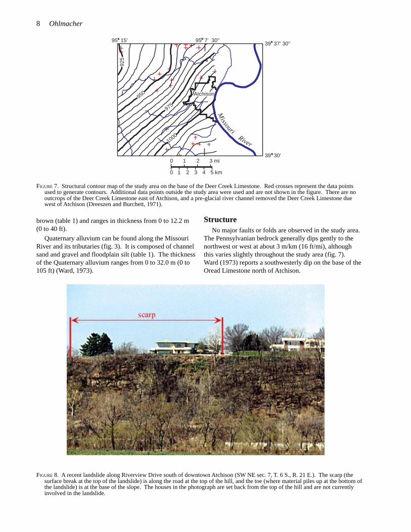
StructureNo major faults or folds are observed in the study area.
The Pennsylvanian bedrock generally dips gently to thenorthwest or west at about 3 m/km (16 ft/mi), althoughthis varies slightly throughout the study area (fig. 7).Ward (1973) reports a southwesterly dip on the base of theOread Limestone north of Atchison.
FIGURE 7. Structural contour map of the study area on the base of the Deer Creek Limestone. Red crosses represent the data pointsused to generate contours. Additional data points outside the study area were used and are not shown in the figure. There are nooutcrops of the Deer Creek Limestone east of Atchison, and a pre-glacial river channel removed the Deer Creek Limestone duewest of Atchison (Dreeszen and Burchett, 1971).
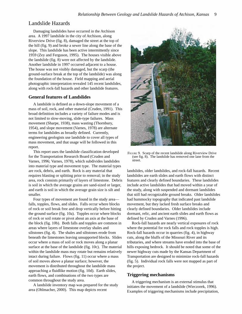
FIGURE 8. A recent landslide along Riverview Drive south of downtown Atchison (SW NE sec. 7, T. 6 S., R. 21 E.). The scarp (thesurface break at the top of the landslide) is along the road at the top of the hill, and the toe (where material piles up at the bottom ofthe landslide) is at the base of the slope. The houses in the photograph are set back from the top of the hill and are not currentlyinvolved in the landslide.
95 15' 95 7' 30'' 39 37' 30''
39 30'0
0
1
1
2
2
3 mi
3 4 5 km
1000
975
950
925
Missour i
River
Atchison
Relationship Between Geology and Landslide Hazards of Atchison, Kansas 9
Landslide HazardsDamaging landslides have occurred in the Atchison
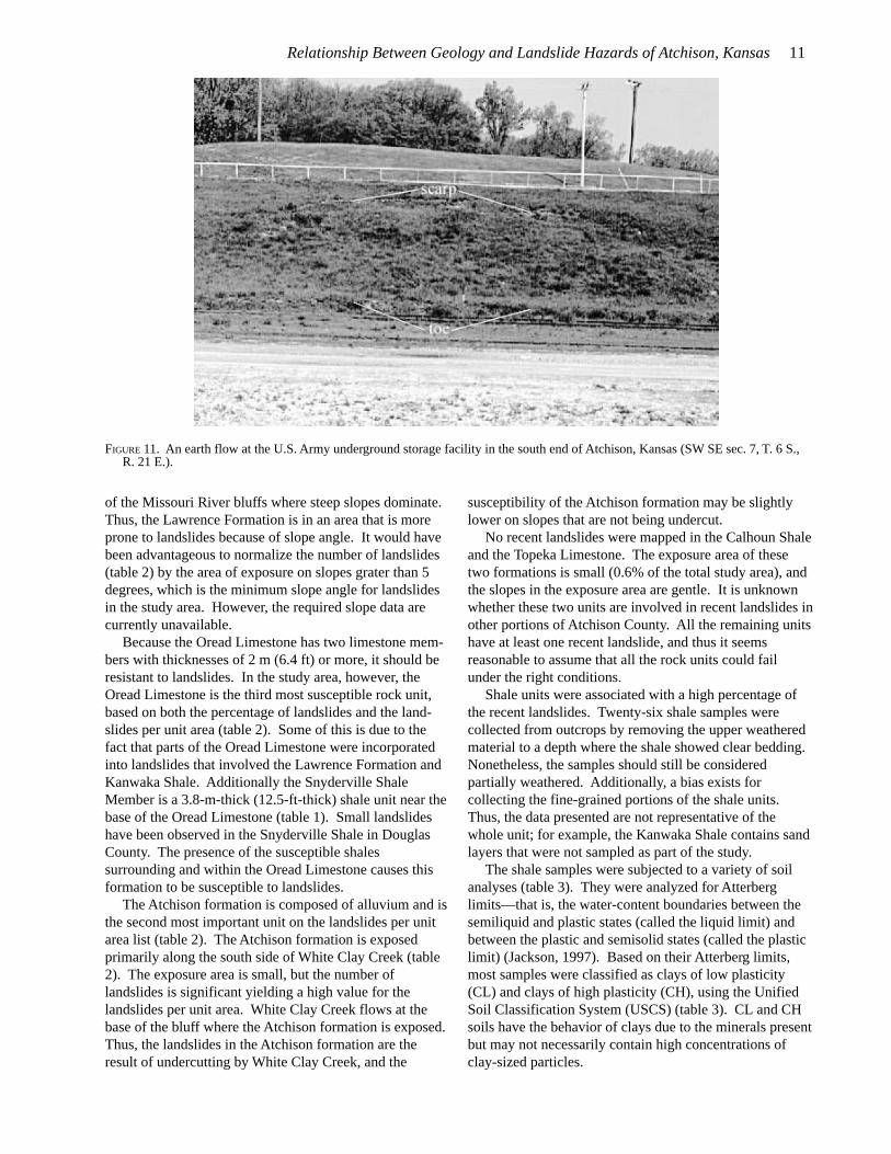
area. A 1997 landslide in the city of Atchison, alongRiverview Drive (fig. 8), damaged the street at the top ofthe hill (fig. 9) and broke a sewer line along the base of theslope. This landslide has been active intermittently since1959 (Zey and Ferguson, 1995). The houses visible abovethe landslide (fig. 8) were not affected by the landslide.Another landslide in 1997 occurred adjacent to a house.The house was not visibly damaged, but the scarp (theground-surface break at the top of the landslide) was alongthe foundation of the house. Field mapping and aerialphotographic interpretation revealed 145 recent landslides,along with rock-fall hazards and other landslide features.
General features of LandslidesA landslide is defined as a down-slope movement of a
mass of soil, rock, and other material (Cruden, 1991). Thisbroad definition includes a variety of failure modes and isnot limited to slow-moving, slide-type failures. Massmovement (Sharpe, 1938), mass wasting (Thornbury,1954), and slope movement (Varnes, 1978) are alternateterms for landslides as broadly defined. Currently,engineering geologists use landslide to cover all types ofmass movement, and that usage will be followed in thisreport.
This report uses the landslide classification developedfor the Transportation Research Board (Cruden andVarnes, 1996; Varnes, 1978), which subdivides landslidesinto material type and movement type. The material typesare rock, debris, and earth. Rock is any material thatrequires blasting or splitting prior to removal; in the studyarea, rock consists primarily of layers of limestone. Debrisis soil in which the average grains are sand-sized or larger,and earth is soil in which the average grain size is silt andsmaller.
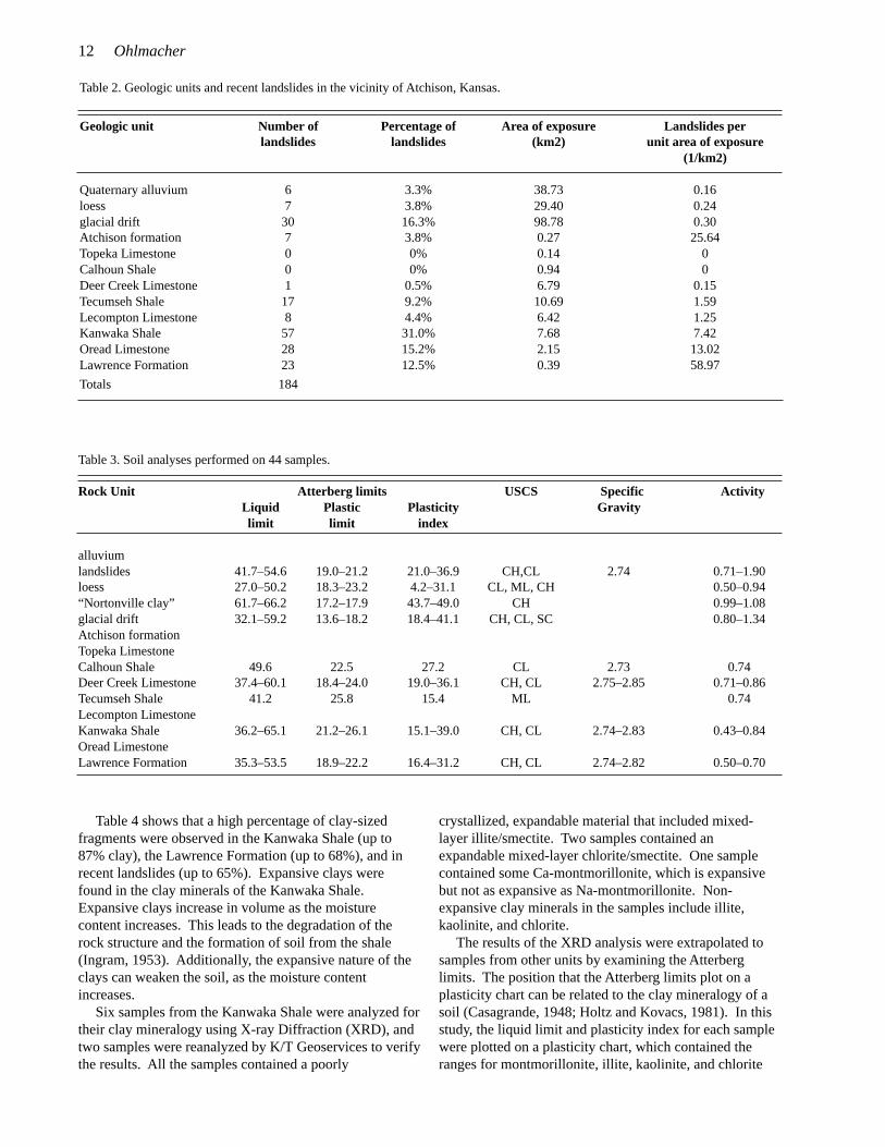
Four types of movement are found in the study area—falls, topples, flows, and slides. Falls occur where blocksof rock or soil break free and drop vertically before hittingthe ground surface (fig. 10a). Topples occur where blocksof rock or soil rotate or pivot about an axis at the base ofthe block (fig. 10b). Both falls and topples are common inareas where layers of limestone overlay shales andsiltstones (fig. 4). The shales and siltstones erode frombeneath the limestones leaving unsupported blocks. Slidesoccur where a mass of soil or rock moves along a planarsurface at the base of the landslide (fig. 10c). The materialwithin the landslide mass may rotate but remains relativelyintact during failure. Flows (fig. 11) occur where a massof soil moves above a planar surface; however, themovement is distributed throughout the landslide massapproaching a fluidlike motion (fig. 10d). Earth slides,earth flows, and combinations of the two types arecommon throughout the study area.
A landslide inventory map was prepared for the studyarea (Ohlmacher, 2000). This map depicts recent
landslides, older landslides, and rock-fall hazards. Recentlandslides are earth slides and earth flows with distinctfeatures and clearly defined boundaries. These landslidesinclude active landslides that had moved within a year ofthe study, along with suspended and dormant landslidesthat still had recognizable ground breaks. Older landslideshad hummocky topography that indicated past landslidemovement, but they lacked fresh surface breaks andclearly defined boundaries. Older landslides includedormant, relic, and ancient earth slides and earth flows asdefined by Cruden and Varnes (1996).
Rock-fall hazards are nearly vertical exposures of rockwhere the potential for rock falls and rock topples is high.Rock-fall hazards occur in quarries (fig. 4), in highwaycuts, along the bluffs of the Missouri River and itstributaries, and where streams have eroded into the base ofhills exposing bedrock. It should be noted that some of thenewer highway cuts made by the Kansas Department ofTransportation are designed to minimize rock-fall hazards(fig. 5). Individual rock falls were not mapped as part ofthe project.
Triggering mechanismsA triggering mechanism is an external stimulus that
initiates the movement of a landslide (Wieczorek, 1996).Examples of triggering mechanisms include precipitation,
FIGURE 9. Scarp of the recent landslide along Riverview Drive(see fig. 8). The landslide has removed one lane from thestreet.

10 Ohlmacher
changes in ground-water levels, snowmelt, stream erosion,and earthquake shaking. Carson (1976) referred to thesemechanisms as short-term triggers. Varnes (1978)observes that landslides can have only one trigger butnumerous causal factors. Causal factors are defined asconditions that contribute to instability but may not initiatefailure. Carson (1976) referred to causal factors as long-term triggers, and his list included slope angle, weak soiland rock units, weathering, mass-movement history, anddeconsolidation. Deconsolidation is the expansion of soilor rock due to unloading or stress relief. Human activitiessuch as excavations and loading of slopes can either betriggering mechanisms or causal factors depending onother slope conditions. For example, if a trench failsfollowing excavation with no other external stimulus, thenthe excavation was the triggering mechanism. However, ifthe trench is open for several days and fails during a
rainstorm, then the excavation contributed to the failureand was a causal factor.
The primary focus of this study was to determinelandslide susceptibility by examining the causal factors.The triggering mechanisms for landslides in the Atchisonstudy area were not determined as part of this study.Triggering mechanisms are very important in studies of theinitiation of individual landslides and in determining theprobability of future landslides.
Causal factors controlling slope stability
Data from recent landslides—combined with geologicmaps, NRCS soil maps, and topographic maps—were usedto identify the causal factors for earth slides and earthflows. Rock-fall hazards were not incorporated in thisstudy because they were previously mapped on thelandslide inventory map (Ohlmacher, 2000). Rock andsoil type, slope angle, and slope line—“an imaginary lineon the ground surface indicating the direction of steepestgradient at a given point, and therefore intersecting thecontour lines at right angles” (Jackson, 1997, p. 599)—were the causal factors examined in this study.
Geology and landslides
Earth slides and earth flows tend to occur in fine-grained materials such as shale and unconsolidatedalluvium. In the study area, the geologic units with themajority of the recent landslides were the Kanwaka Shale(57 landslides), glacial drift (30), the Oread Limestone(28), the Lawrence Formation (23), and the TecumsehShale (17) (table 2). However, these numbers aremisleading because they do not take into account theextent of each unit’s exposure in the study area. Forexample, glacial drift is exposed over 98.78 km2 (38.41mi2), whereas the Lawrence Formation only is exposedover 0.39 km2 (0.15 mi2). When the 23 landslides thatoccurred in the Lawrence Formation are divided by thearea of exposure, the number of landslides per unit area is59 (table 2). This number is a better indicator of ageologic formation’s susceptibility—Lawrence Formation(59) and glacial drift (0.3)—than the number of landslidestaken alone.
The geologic unit in the study area with the mostlandslides per unit area of exposure is the LawrenceFormation (table 2). This finding agrees with the generalperception of the Lawrence Formation as one of morelandslide-prone rock units in northeast Kansas (F. Wilson,personal communication, 1997; D. Thompson, personalcommunication, 1999). After the Lawrence Formation, themost susceptible units are the Atchison formation, theOread Limestone, and the Kanwaka Shale.
The distribution of slope angles within a geologic unit’soutcrop area also affects the susceptibility ranking of eachunit. Glacial drift is located at the tops of hills and in thewestern portion of the study area where gentle slopesdominate. The Lawrence Formation is located at the base
FIGURE 10. Different types of landslide movement. (A) Fallsoccur where a block of material free-falls from a slope. (B)Topples involve rotation of a block of material along an axisat the base of the block. (C) Slides occur where a relativelyintact mass of material moves along a basal failure plane. (D)Flows occur where motion is distributed throughout thelandslide mass approaching fluid-like behavior.
topplepivot
fall
flow
slide
(A)
(B)
(C)
(D)
Relationship Between Geology and Landslide Hazards of Atchison, Kansas 11
of the Missouri River bluffs where steep slopes dominate.Thus, the Lawrence Formation is in an area that is moreprone to landslides because of slope angle. It would havebeen advantageous to normalize the number of landslides(table 2) by the area of exposure on slopes grater than 5degrees, which is the minimum slope angle for landslidesin the study area. However, the required slope data arecurrently unavailable.
Because the Oread Limestone has two limestone mem-bers with thicknesses of 2 m (6.4 ft) or more, it should beresistant to landslides. In the study area, however, theOread Limestone is the third most susceptible rock unit,based on both the percentage of landslides and the land-slides per unit area (table 2). Some of this is due to thefact that parts of the Oread Limestone were incorporatedinto landslides that involved the Lawrence Formation andKanwaka Shale. Additionally the Snyderville ShaleMember is a 3.8-m-thick (12.5-ft-thick) shale unit near thebase of the Oread Limestone (table 1). Small landslideshave been observed in the Snyderville Shale in DouglasCounty. The presence of the susceptible shalessurrounding and within the Oread Limestone causes thisformation to be susceptible to landslides.
The Atchison formation is composed of alluvium and isthe second most important unit on the landslides per unitarea list (table 2). The Atchison formation is exposedprimarily along the south side of White Clay Creek (table2). The exposure area is small, but the number oflandslides is significant yielding a high value for thelandslides per unit area. White Clay Creek flows at thebase of the bluff where the Atchison formation is exposed.Thus, the landslides in the Atchison formation are theresult of undercutting by White Clay Creek, and the
susceptibility of the Atchison formation may be slightlylower on slopes that are not being undercut.
No recent landslides were mapped in the Calhoun Shaleand the Topeka Limestone. The exposure area of thesetwo formations is small (0.6% of the total study area), andthe slopes in the exposure area are gentle. It is unknownwhether these two units are involved in recent landslides inother portions of Atchison County. All the remaining unitshave at least one recent landslide, and thus it seemsreasonable to assume that all the rock units could failunder the right conditions.
Shale units were associated with a high percentage ofthe recent landslides. Twenty-six shale samples werecollected from outcrops by removing the upper weatheredmaterial to a depth where the shale showed clear bedding.Nonetheless, the samples should still be consideredpartially weathered. Additionally, a bias exists forcollecting the fine-grained portions of the shale units.Thus, the data presented are not representative of thewhole unit; for example, the Kanwaka Shale contains sandlayers that were not sampled as part of the study.
The shale samples were subjected to a variety of soilanalyses (table 3). They were analyzed for Atterberglimits—that is, the water-content boundaries between thesemiliquid and plastic states (called the liquid limit) andbetween the plastic and semisolid states (called the plasticlimit) (Jackson, 1997). Based on their Atterberg limits,most samples were classified as clays of low plasticity(CL) and clays of high plasticity (CH), using the UnifiedSoil Classification System (USCS) (table 3). CL and CHsoils have the behavior of clays due to the minerals presentbut may not necessarily contain high concentrations ofclay-sized particles.
FIGURE 11. An earth flow at the U.S. Army underground storage facility in the south end of Atchison, Kansas (SW SE sec. 7, T. 6 S.,R. 21 E.).
12 Ohlmacher
Table 2. Geologic units and recent landslides in the vicinity of Atchison, Kansas.
Geologic unit Number of Percentage of Area of exposure Landslides perlandslides landslides (km2) unit area of exposure
(1/km2)
Quaternary alluvium 6 3.3% 38.73 0.16loess 7 3.8% 29.40 0.24glacial drift 30 16.3% 98.78 0.30Atchison formation 7 3.8% 0.27 25.64Topeka Limestone 0 0% 0.14 0Calhoun Shale 0 0% 0.94 0Deer Creek Limestone 1 0.5% 6.79 0.15Tecumseh Shale 17 9.2% 10.69 1.59Lecompton Limestone 8 4.4% 6.42 1.25Kanwaka Shale 57 31.0% 7.68 7.42Oread Limestone 28 15.2% 2.15 13.02Lawrence Formation 23 12.5% 0.39 58.97
Totals 184
Table 3. Soil analyses performed on 44 samples.
Rock Unit Atterberg limits USCS Specific ActivityLiquid Plastic Plasticity Gravitylimit limit index
alluviumlandslides 41.7–54.6 19.0–21.2 21.0–36.9 CH,CL 2.74 0.71–1.90loess 27.0–50.2 18.3–23.2 4.2–31.1 CL, ML, CH 0.50–0.94“Nortonville clay” 61.7–66.2 17.2–17.9 43.7–49.0 CH 0.99–1.08glacial drift 32.1–59.2 13.6–18.2 18.4–41.1 CH, CL, SC 0.80–1.34Atchison formationTopeka LimestoneCalhoun Shale 49.6 22.5 27.2 CL 2.73 0.74Deer Creek Limestone 37.4–60.1 18.4–24.0 19.0–36.1 CH, CL 2.75–2.85 0.71–0.86Tecumseh Shale 41.2 25.8 15.4 ML 0.74Lecompton LimestoneKanwaka Shale 36.2–65.1 21.2–26.1 15.1–39.0 CH, CL 2.74–2.83 0.43–0.84Oread LimestoneLawrence Formation 35.3–53.5 18.9–22.2 16.4–31.2 CH, CL 2.74–2.82 0.50–0.70
Table 4 shows that a high percentage of clay-sizedfragments were observed in the Kanwaka Shale (up to87% clay), the Lawrence Formation (up to 68%), and inrecent landslides (up to 65%). Expansive clays werefound in the clay minerals of the Kanwaka Shale.Expansive clays increase in volume as the moisturecontent increases. This leads to the degradation of therock structure and the formation of soil from the shale(Ingram, 1953). Additionally, the expansive nature of theclays can weaken the soil, as the moisture contentincreases.
Six samples from the Kanwaka Shale were analyzed fortheir clay mineralogy using X-ray Diffraction (XRD), andtwo samples were reanalyzed by K/T Geoservices to verifythe results. All the samples contained a poorly
crystallized, expandable material that included mixed-layer illite/smectite. Two samples contained anexpandable mixed-layer chlorite/smectite. One samplecontained some Ca-montmorillonite, which is expansivebut not as expansive as Na-montmorillonite. Non-expansive clay minerals in the samples include illite,kaolinite, and chlorite.
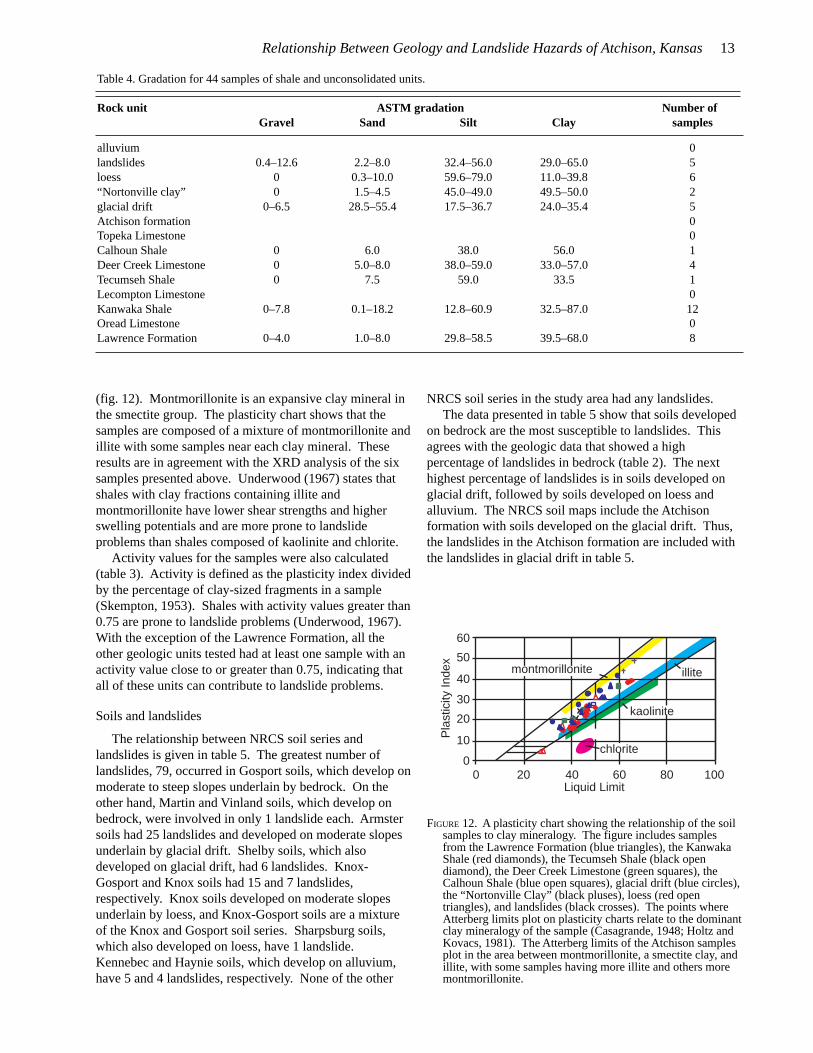
The results of the XRD analysis were extrapolated tosamples from other units by examining the Atterberglimits. The position that the Atterberg limits plot on aplasticity chart can be related to the clay mineralogy of asoil (Casagrande, 1948; Holtz and Kovacs, 1981). In thisstudy, the liquid limit and plasticity index for each samplewere plotted on a plasticity chart, which contained theranges for montmorillonite, illite, kaolinite, and chlorite
Relationship Between Geology and Landslide Hazards of Atchison, Kansas 13
Table 4. Gradation for 44 samples of shale and unconsolidated units.
Rock unit ASTM gradation Number ofGravel Sand Silt Clay samples
alluvium 0landslides 0.4–12.6 2.2–8.0 32.4–56.0 29.0–65.0 5loess 0 0.3–10.0 59.6–79.0 11.0–39.8 6“Nortonville clay” 0 1.5–4.5 45.0–49.0 49.5–50.0 2glacial drift 0–6.5 28.5–55.4 17.5–36.7 24.0–35.4 5Atchison formation 0Topeka Limestone 0Calhoun Shale 0 6.0 38.0 56.0 1Deer Creek Limestone 0 5.0–8.0 38.0–59.0 33.0–57.0 4Tecumseh Shale 0 7.5 59.0 33.5 1Lecompton Limestone 0Kanwaka Shale 0–7.8 0.1–18.2 12.8–60.9 32.5–87.0 12Oread Limestone 0Lawrence Formation 0–4.0 1.0–8.0 29.8–58.5 39.5–68.0 8
(fig. 12). Montmorillonite is an expansive clay mineral inthe smectite group. The plasticity chart shows that thesamples are composed of a mixture of montmorillonite andillite with some samples near each clay mineral. Theseresults are in agreement with the XRD analysis of the sixsamples presented above. Underwood (1967) states thatshales with clay fractions containing illite andmontmorillonite have lower shear strengths and higherswelling potentials and are more prone to landslideproblems than shales composed of kaolinite and chlorite.
Activity values for the samples were also calculated(table 3). Activity is defined as the plasticity index dividedby the percentage of clay-sized fragments in a sample(Skempton, 1953). Shales with activity values greater than0.75 are prone to landslide problems (Underwood, 1967).With the exception of the Lawrence Formation, all theother geologic units tested had at least one sample with anactivity value close to or greater than 0.75, indicating thatall of these units can contribute to landslide problems.
Soils and landslides
The relationship between NRCS soil series andlandslides is given in table 5. The greatest number oflandslides, 79, occurred in Gosport soils, which develop onmoderate to steep slopes underlain by bedrock. On theother hand, Martin and Vinland soils, which develop onbedrock, were involved in only 1 landslide each. Armstersoils had 25 landslides and developed on moderate slopesunderlain by glacial drift. Shelby soils, which alsodeveloped on glacial drift, had 6 landslides. Knox-Gosport and Knox soils had 15 and 7 landslides,respectively. Knox soils developed on moderate slopesunderlain by loess, and Knox-Gosport soils are a mixtureof the Knox and Gosport soil series. Sharpsburg soils,which also developed on loess, have 1 landslide.Kennebec and Haynie soils, which develop on alluvium,have 5 and 4 landslides, respectively. None of the other
NRCS soil series in the study area had any landslides.The data presented in table 5 show that soils developed
on bedrock are the most susceptible to landslides. Thisagrees with the geologic data that showed a highpercentage of landslides in bedrock (table 2). The nexthighest percentage of landslides is in soils developed onglacial drift, followed by soils developed on loess andalluvium. The NRCS soil maps include the Atchisonformation with soils developed on the glacial drift. Thus,the landslides in the Atchison formation are included withthe landslides in glacial drift in table 5.
100806040200
60
50
40
30
20
10
0
Liquid Limit
Pla
stic
ity In
dex
illite
kaolinite
chlorite
montmorillonite
FIGURE 12. A plasticity chart showing the relationship of the soilsamples to clay mineralogy. The figure includes samplesfrom the Lawrence Formation (blue triangles), the KanwakaShale (red diamonds), the Tecumseh Shale (black opendiamond), the Deer Creek Limestone (green squares), theCalhoun Shale (blue open squares), glacial drift (blue circles),the “Nortonville Clay” (black pluses), loess (red opentriangles), and landslides (black crosses). The points whereAtterberg limits plot on plasticity charts relate to the dominantclay mineralogy of the sample (Casagrande, 1948; Holtz andKovacs, 1981). The Atterberg limits of the Atchison samplesplot in the area between montmorillonite, a smectite clay, andillite, with some samples having more illite and others moremontmorillonite.
14 Ohlmacher
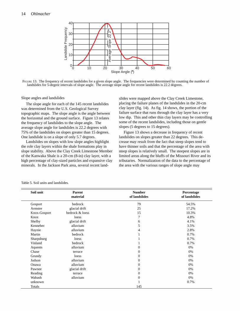
FIGURE 13. The frequency of recent landslides for a given slope angle. The frequencies were determined by counting the number oflandslides for 5-degree intervals of slope angle. The average slope angle for recent landslides is 22.2 degrees.
Slope angles and landslides
The slope angle for each of the 145 recent landslideswas determined from the U.S. Geological Surveytopographic maps. The slope angle is the angle betweenthe horizontal and the ground surface. Figure 13 relatesthe frequency of landslides to the slope angle. Theaverage slope angle for landslides is 22.2 degrees with75% of the landslides on slopes greater than 15 degrees.One landslide is on a slope of only 5.7 degrees.
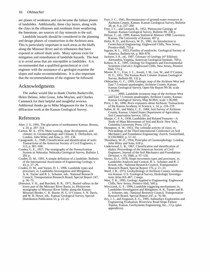
Landslides on slopes with low slope angles highlightthe role clay layers within the shale formations play inslope stability. Above the Clay Creek Limestone Memberof the Kanwaka Shale is a 20-cm (8-in) clay layer, with ahigh percentage of clay-sized particles and expansive clayminerals. In the Jackson Park area, several recent land-
slides were mapped above the Clay Creek Limestone,placing the failure planes of the landslides in the 20-cmclay layer (fig. 14). As fig. 14 shows, the portion of thefailure surface that runs through the clay layer has a verylow dip. This and other thin clay layers may be controllingsome of the recent landslides, including those on gentleslopes (5 degrees to 15 degrees).
Figure 13 shows a decrease in frequency of recentlandslides on slopes greater than 22 degrees. This de-crease may result from the fact that steep slopes tend tohave thinner soils and that the percentage of the area withsteep slopes is relatively small. The steepest slopes are inlimited areas along the bluffs of the Missouri River and itstributaries. Normalization of the data to the percentage ofthe area with the various ranges of slope angle may
Table 5. Soil units and landslides.
Soil unit Parent Number Percentagematerial of landslides of landslides
Gosport bedrock 79 54.5%Armster glacial drift 25 17.2%Knox-Gosport bedrock & loess 15 10.3%Knox loess 7 4.8%Shelby glacial drift 6 4.1%Kennebec alluvium 5 3.5%Haynie alluvium 4 2.8%Martin bedrock 1 0.7%Sharpsburg loess 1 0.7%Vinland bedrock 1 0.7%Aquents alluvium 0 0%Chase terrace 0 0%Grundy loess 0 0%Judson alluvium 0 0%Onawa alluvium 0 0%Pawnee glacial drift 0 0%Reading terrace 0 0%Wabash alluvium 0 0%unknown 1 0.7%Totals 145
Slope Angle ( )
Land
slid
e F
requ
ency
0 10 20 30 40 50 60
40
30
20
10
0
Ave
rage
Slo
pe 2
2.2

Relationship Between Geology and Landslide Hazards of Atchison, Kansas 15
N
15
10
5
FIGURE 14. Diagram of the failure plane of a landslide in the Kanwaka Shale. The clay layer above the Clay Creek LimestoneMember is weak, and the failure plane of the landslide would be located within this layer. Earth slides and earth flows on gentleslopes (5 degrees to 15 degrees) may be the result of thin, weak clay layers.
not to scale
Clay Creek Limestone
Stull Shale
Jackson Park Shale
clay layer {failure plane
landslide
silty &sandy shale
provide a more realistic assessment of the role of slopeangle in landsliding, but the slope data required for doingthe normalization were not available when this report waswritten.
Slope line and landslides
According to conventional wisdom, landslides are morelikely to occur on slopes with slope lines to the north(north-facing slopes). The hypothesis is that less directsunlight and slightly cooler temperatures lead to lessevaporation and more moisture in the soils on north-facingslopes. Slope lines for the recent landslides are plotted infig. 15. Two maxima are observed in figure 15. The firstranges from the northeast to southeast and coincides withthe slope lines for the Missouri River bluffs (the yellowarea in fig. 15). The second maximum is to the northwest.
FIGURE 15. Rose diagram showing the slope lines for the recentlandslides. Two maxima are observed in the data. The firstis from northeast to southeast and is related to the bluffs ofthe Missouri River (yellow area in figure). The second is tothe northwest and may be related to ground-water flow.
This is partially due to the fact that Deer, White Clay, andWalnut creeks tend to flow along the southern side of theirvalleys, eroding the toe of the northwest-facing slopes.Ground-water flow may also contribute to landslides onslopes with slope lines to the northwest. Precipitation thatinfiltrates at the top of a hill migrates down until it reachesan impermeable layer and then flows above theimpermeable layer to the face of the hill. An example ofan impermeable layer is the clay layer above the ClayCreek Limestone Member (fig. 14). Bedrock in the studyarea dips very gently to the northwest and west (fig. 7).When ground water reaches the impermeable layer, itwould flow to the northwest and exit on slopes with slopelines to the northwest, west, and north, increasing thesusceptibility of these slopes to landslides.
Conclusions
The key factors contributing to landslide problems inthe study area include slope angle, hydrology, geology,soils, and slope line. Rock-fall and rock-topple hazardsare associated with areas of exposed limestone—especiallyareas where exposed limestones overlie shales that arebeing eroded. Recent landslides, which are dominantlyearth slides and earth flows, generally occurred in bedrockand soil developed on bedrock, but almost every rock unitmapped in the area had at least one recent landslide. Shaleformations were more susceptible than limestoneformations to slope failures; however, weak shalemembers of limestone formations can also cause problems.Recent landslides occurred on moderate to steep slopes,but some are found on gentle slopes (5 degrees to 15degrees). Recent landslides were most likely to occur onslopes with either southeast to northeast or northwestorientations. The Lawrence Formation was the mostlandslide prone unit.
Thin (less than 0.3 m or 1.0 ft) clay layers within theshale formations and the shale members of limestoneformations play an important role in causing landslides.These layers have a high percentage of clay-sized par-ticles, which include expansive clays. Thus, these layers
16 Ohlmacher
are planes of weakness and can become the failure planesof landslides. Additionally, these clay layers, along withthe clays in the siltstones and residuum from weatheringthe limestone, are sources of clay minerals to the soil.
Landslide hazards should be considered in the planningand design phases of construction in the Atchison area.This is particularly important in such areas as the bluffsalong the Missouri River and its tributaries that haveexposed or subsoil shale units. Many options exist formitigation and remediation of landslide hazards. The bestis to avoid areas that are susceptible to landslides. It isrecommended that a qualified geotechnical or civilengineer with the assistance of a geologist examine theslopes and make recommendations. It is also importantthat the recommendations of the engineer be followed.
AcknowledgmentsThe author would like to thank Charles Baskerville,
Helen Delano, John Gosse, John Moylan, and CharlesCammack for their helpful and insightful reviews.Additional thanks go to Mike Magnuson for the X-raydiffraction work at the Kansas Geological Survey.
ReferencesAber, J. S., 1991, The glaciation of northeastern Kansas: Boreas,
v. 20, p. 297–314.Carson, M. A., 1976, Mass-wasting, slope development, and
climate; in, Geomorphology and Climate, E. Derbyshire, ed.:London, John Wiley and Sons, p. 101–136.
Casagrande, A., 1948, Classification and identification of soils:Transactions of the American Society of Civil Engineers, v.113, p. 901–930.
Condra, G. E., 1927, The stratigraphy of the PennsylvanianSystem in Nebraska: Nebraska Geological Survey, Bulletin 1,291 p.
Cruden, D. M., 1991, A simple definition of a landslide: Bulletinof the International Association of Engineering Geology, v.43, p. 27–29.
Cruden, D. M., and Varnes, D. J., 1996, Landslide types andprocesses; in, Landslides Investigation and Mitigation,A. K. Turner and R. L. Schuster, eds.: National ResearchCouncil, Transportation Research Board, Special Report 247,p. 36–75.
Dreeszen, V. H., and Burchett, R. R., 1971, Buried valleys in thelower part of the Missouri River Basin; in, Pleistocenestratigraphy of Missouri River Valley along the Kansas-Missouri Border, C. K. Bayne, H. G. O’Connor, S. N. Davis,and W. B. Howe, eds.: Kansas Geological Survey, SpecialDistribution Publication 53, p. 21–25.
Frye, J. C., 1941, Reconnaissance of ground-water resources inAtchison County, Kansas: Kansas Geological Survey, Bulletin38, pt. 9, p. 237–260.
Frye, J. C., and Leonard, B., 1952, Pleistocene Geology ofKansas: Kansas Geological Survey, Bulletin 99, 230 p.
Helyar, T., ed., 1999, Kansas Statistical Abstract 1998: Lawrence,Kansas, The University of Kansas, 467 p.
Holtz, R. D., and Kovacs, W. D., 1981, An Introduction toGeotechnical Engineering: Englewood Cliffs, New Jersey,Prentice-Hall, 733 p.
Ingram, R. L., 1953, Fissility of mudrocks: Geological Society ofAmerica, Bulletin 64, p. 869–878.
Jackson, J. A., ed., 1997, Glossary of Geology (4th Edition):Alexandria, Virginia, American Geological Institute, 769 p.
Kehew, A. E., 1995, Geology for Engineers and EnvironmentalScientists (2nd ed.): Englewood Cliffs, New Jersey, PrenticeHall, 574 p.
Moore, R. C., Frye, J. C., Jewett, J. M., Lee, W., and O’Connor,H. G., 1951, The Kansas Rock Column: Kansas GeologicalSurvey, Bulletin 89, 132 p.
Ohlmacher, G. C., 1999, Geologic map of the Atchison West andEast 7.5-minute quadrangles, Atchison County, Kansas:Kansas Geological Survey, Open-file Report 99-38, scale1:36,000.
________, 2000, Landslide inventory map of the Atchison Westand East 7.5-minute quadrangles, Atchison County, Kansas:Kansas Geological Survey, Map M-89A, scale 1:36,000.
Price, J. M., 1896, Rock exposures about Atchison: Transactionsof the Kansas Academy of Science, v. 14, p. 218–219.
Sallee, K. H., and Watts, C. E., 1984, Soil Survey of AtchisonCounty, Kansas: United States Department of Agriculture,Soil Conservation Service, 105 p.
Sharpe, C. F. S., 1938, Landslides and Related Features—AStudy of Mass Movements of Soil and Rock: New York,Columbia University Press, 137 p.
Skempton, A. W., 1953, The colloidal activity of clays; in,Proceedings of the Third International Conference on SoilMechanics and Foundation Engineering: Zurich, Switzerland,ICOSOMEF, p. 57–61.
Thornbury, W. D., 1954, Principles of Geomorphology: London,John Wiley and Sons, 618 p.
Underwood, L. B., 1967, Classification and identification ofshales: Proceedings of the American Society of CivilEngineers, Journal of the Soil Mechanics and FoundationsDivision, v. 93, SM6, p. 97–116.
Varnes, D. J., 1978, Slope movement types and processes; in,Landslides Analysis and Control, R. L. Schuster and R. J.Krizek, eds.: National Research Council, TransportationResearch Board, Special Report 176, p. 11–33.
Ward, J. R., 1973, Geohydrology of Atchison County, northeast-ern Kansas: U.S. Geological Survey, Hydrologic Investiga-tions Atlas HA-467, 2 maps.
West, T. R., 1995, Geology Applied to Engineering: EnglewoodCliffs, New Jersey, Prentice Hall, 560 p.
Wieczorek, G. F., 1996, Landslide triggering mechanisms; in,Landslides Investigation and Mitigation, A. K. Turner and R.L. Schuster, eds.: National Research Council, TransportationResearch Board, Special Report 247, p. 76–90.
Zey, J. J., and Ferguson, E. G., 1995, Subsurface Exploration andEngineering Evaluation, Riverview Road Slope Failure:Topeka, Kansas, GeoSystems Engineering, Inc., 13 p. (plusappendices).