The range of application of ORC power plant in power ...
5
* Corresponding author: [email protected] The range of application of ORC power plant in power stations fed with low and medium thermal sources Tomasz Kujawa 1,* , and Władysław Nowak 1 1 West-Pomeranian University of Technology, Szczecin, Department of Heat Engineering, al. Piastów 17, PL-70-310 Szczecin, Poland Abstract. The work presents the diagrams of the applied power plant solutions with a description of their operation and calculation algorithm. In the latter case, the cycle of thermodynamic transformations of the Rankine cycle presented in the T-s coordinate system was used, which reflects the subsequent transformations occurring in individual devices of the power plant, including the method of determining unit quantities characterizing their operation. The energy balance equations of the evaporator and the heater are presented, which among other things will be the basis for determining the coefficient that plays an important role in determining the range of applications of the single-circuit sub-critical power plant in the power plant/CHP plant. The coefficient φ was defined as the ratio of the mass stream of water flowing through the counter-current heat exchanger in which the liquid of the working medium is heated within the limits of condensation and evaporation temperatures, to the mass stream of water leaving the evaporator according to the dependence s s m m 1 = φ . It has been assumed that a given mass stream of water s m at a given temperature 1 s T is heated in a heat exchanger which is the upper heat source. The calculations of the power plant for selected working fluids (R227ea, RC318, R1234ze and R1234yf) were made for different evaporation temperatures taking into account near-subcritical temperatures for selected supply water temperatures. On this basis, the figures ( ) EVAP T f = φ illustrating the application ranges of a single-circuit power plant in a power plant/CHP plant were drawn up. The analysis of the above figures became the basis for formulating final conclusions. 1 Introduction The starting point of the considerations presented in the work is an organic power plant, in which a subcritical single-circuit power plant with a dry working medium was used. The power plant is supplied with geothermal water (Fig. 1) [1-6]. Fig. 1. Diagram of the plant installation working with dry medium. The principle of operation of the ORC power plant is the same as for a steam power plant. Figure 2 presents cycles of thermodynamic transformations of the power plant, also the temperatures of the energy carrier in the relevant characteristic points are marked. Fig. 2. Cycle of thermodynamic transformations of subcritical ORC cycle with dry factor [2]. ORC power plant with dry medium as a working medium consists of an evaporator, a heater, a turbine, a condenser and a circulation pump of an organic medium. ,0 0 (2018) https://doi.org/10.1051/e3sconf/2018 09 E3S Web of Conferences 70 10 70010 HTRSE-2018 9 © The Authors, published by EDP Sciences. This is an open access article distributed under the terms of the Creative Commons Attribution License 4.0 (http://creativecommons.org/licenses/by/4.0/).
Transcript of The range of application of ORC power plant in power ...

* Corresponding author: [email protected]
The range of application of ORC power plant in power stations fed with low and medium thermal sources
Tomasz Kujawa1,*, and Władysław Nowak1 1West-Pomeranian University of Technology, Szczecin, Department of Heat Engineering, al. Piastów 17, PL-70-310 Szczecin, Poland
Abstract. The work presents the diagrams of the applied power plant solutions with a description of their operation and calculation algorithm. In the latter case, the cycle of thermodynamic transformations of the Rankine cycle presented in the T-s coordinate system was used, which reflects the subsequent transformations occurring in individual devices of the power plant, including the method of determining unit quantities characterizing their operation. The energy balance equations of the evaporator and the heater are presented, which among other things will be the basis for determining the coefficient that plays an important role in determining the range of applications of the single-circuit sub-critical power plant in the power plant/CHP plant. The coefficient φ was defined as the ratio of the mass stream of water flowing
through the counter-current heat exchanger in which the liquid of the working medium is heated within the limits of condensation and evaporation temperatures, to the mass stream of water leaving the evaporator according to the dependence ss mm 1=φ . It has been assumed that a given mass stream of water sm at a
given temperature 1sT is heated in a heat exchanger which is the upper heat source. The calculations of the
power plant for selected working fluids (R227ea, RC318, R1234ze and R1234yf) were made for different evaporation temperatures taking into account near-subcritical temperatures for selected supply water temperatures. On this basis, the figures ( )EVAPTf=φ illustrating the application ranges of a single-circuit power plant in a power plant/CHP plant were drawn up. The analysis of the above figures became the basis for formulating final conclusions.
1 Introduction The starting point of the considerations presented in
the work is an organic power plant, in which a subcritical single-circuit power plant with a dry working medium was used. The power plant is supplied with geothermal water (Fig. 1) [1-6].
Fig. 1. Diagram of the plant installation working with dry medium.
The principle of operation of the ORC power plant is the same as for a steam power plant. Figure 2 presents cycles of thermodynamic transformations of the power plant, also the temperatures of the energy carrier in the relevant characteristic points are marked.
Fig. 2. Cycle of thermodynamic transformations of subcritical ORC cycle with dry factor [2].
ORC power plant with dry medium as a working medium consists of an evaporator, a heater, a turbine, a condenser and a circulation pump of an organic medium.
, 0 0 (2018) https://doi.org/10.1051/e3sconf/2018 09E3S Web of Conferences 70 10 70010HTRSE-2018
9
© The Authors, published by EDP Sciences. This is an open access article distributed under the terms of the Creative Commons Attribution License 4.0 (http://creativecommons.org/licenses/by/4.0/).

The curves shown in Fig. 2 reflect subsequent changes taking place in the individual devices of the system: • transformation 1-2s - isentropic vapour expansion of the organic agent in the turbine, • transformation 2s-3 –cooling and condensation of the medium vapour in the condenser, • transformation 3-4s – isentropic pumping of an organic agent in a circulating pump, • transformation 4s-5 – heating the organic medium in a heater-type exchanger from the condensation temperature to the evaporation temperature, • transformation 5-1 – evaporation of the organic agent in the evaporator.
It has been assumed that a given mass stream of water sm at a given temperature 1sT is heated in a heat exchanger which is the upper heat source.
2 Variants of the power plant operation and calculation algorithm For calculations the energy balance equations of the evaporator and the heater were used.
The equation for the energy balance of the evaporator can be written as follows:
( ) ( )[ ] EVAPnsssssEVAP hmThThmQ ∆⋅=′−′⋅= 2211 , (1)
while the equation of the energy balance of the heater in the form:
( ) ( )[ ] HEATnsssssHEAT hmThThmQ ∆⋅=′−′⋅= 3322 . (2)
The coefficient φ was defined as the ratio of the mass stream of water 1sm flowing through the counter-current heat exchanger in which the liquid of the working medium is heated within the condensing and evaporating temperatures to the mass stream of water sm leaving the evaporator according to the dependence:
ss mm 1=φ . (3)
The tests show that for the above-mentioned power plant the coefficient φ generally fulfills the condition 1≤φ . If 1=φ , the above single-circuit power plant is applicable only to the power plant.
In this case, the water jet leaving the evaporator sm is equal to the mass flow of water 1sm which feeds the heater, that means that 1ss mm = . The size of the coefficient φ (at the same stream of feed water sm and at the same temperature 1sT ) is influenced by: the type of dry working medium of the power plant and the type of operation of the evaporator in the power plant. The latter includes the following temperature differences: • drop in feed water temperature
21 sss TTT −=∆ (4)
equal to the difference in water temperature at the inlet 1sT and at the outlet 2sT of the evaporator,
• temperature difference
EVAPss TTT −=∆ 11 (5)
as the temperature difference between the water supplying the evaporator 1sT and the evaporating temperature of the working medium EVAPT , • temperature difference
EVAPss TTT −=∆ 22 (6)
as the temperature difference between the water leaving the evaporator 2sT and the evaporating temperature of the working medium EVAPT . It is easy to show that between the given temperature differences sT∆ , 1sT∆ , 2sT∆ there is a dependence:
21 sss TTT ∆−∆=∆ (7)
If it is not possible to utilize heat for technological and heating purposes, the power plant solution for 1<φ was also used in the power plant (Figure 3). It allowed to take into account the continuity of changes φ in the characteristics of the power plant operation and to develop a full range of the power plant operation characteristics in the power plant for 1≤φ which is the basic area for this work characteristic. If 1=φ then
1ss mm = , which means that 02 =sm . In this case, the cable connecting the node A to the
node B in Fig. 3 is not needed.
Fig. 3. Diagram of a single-circuit ORC plant used in a power plant for 1≤φ .
The work carried out at the Department of Heat Engineering [1, 2] showed that the coefficient φ may be equal to and less than one ( 1≤φ ), and also greater than one ( 1>φ ) and then covers the second area of the operating range of the power plant in a hybrid power plant. In this second area of the power plant performance at the power plant, just like in the case of a power plant for 1=φ , the mass flow of water sm at the temperature
, 0 0 (2018) https://doi.org/10.1051/e3sconf/2018 09E3S Web of Conferences 70 10 70010HTRSE-2018
9
2
2sT leaving the evaporator is directed to the fluid heater of the power plant working medium (Fig. 4). This stream of water sm after lowering its temperature to 3sT is directed to the first heat exchanger, which is the upper heat source of the installation. This stream, after reaching the temperature 1sT , is directed to the power plant evaporator again.
Fig. 4. Diagram of a single-circuit ORC plant used in a power plant for 1>φ .
The required stream of water 1sm , which should be fed to the fluid heater of the working medium, is determined from the definition of coefficient φ (3). The stream is:
φ⋅= ss mm 1 . (8)
Considering that the mass flow of water sm from the evaporator was directly supplied to the fluid heater of the working medium of the plant, after taking into account dependence (8), an additional mass stream of water
1sm∆ should be fed to the liquid heater of the working medium, whose size can be determined from the dependence below:
( )111 −=−=∆ φssss mmmm , (9)
for 1>φ . This stream ( 1sm∆ ) after increasing the temperature to the value 2sT is supplied to the fluid heater of the working medium of the power plant, in which after lowering the temperature to the value 3sT it is directed again to the second heat source. After taking into account the balance of the evaporator and the condenser, the value of the coefficient φ can be determined from the dependence:
( )( ) EVAP
HEAT
sPAR
s
EVAP
HEAT
s
sshh
TTT
hh
TTTT
∆∆⋅
−∆
=∆∆⋅
−∆−∆
=445
21φ .
(10)
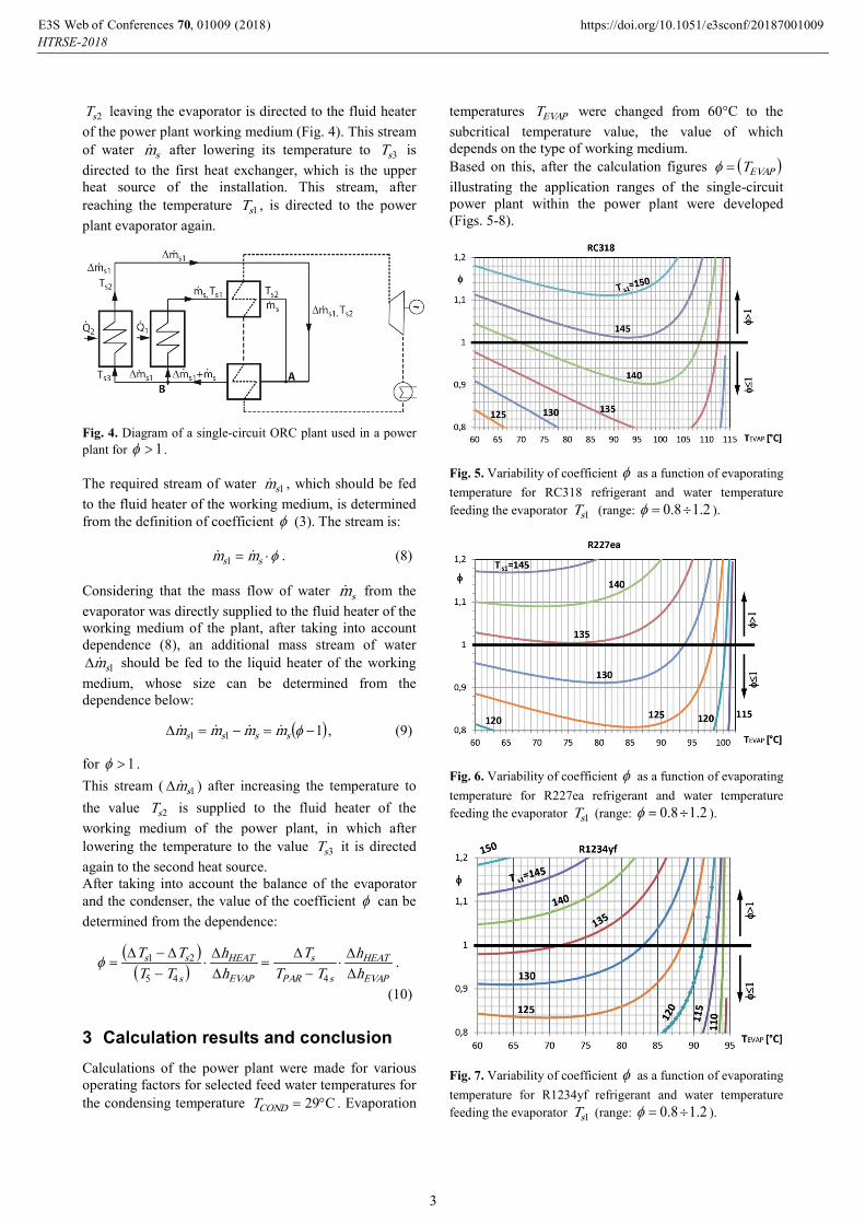
3 Calculation results and conclusion Calculations of the power plant were made for various operating factors for selected feed water temperatures for the condensing temperature C29°=CONDT . Evaporation
temperatures EVAPT were changed from 60°C to the subcritical temperature value, the value of which depends on the type of working medium. Based on this, after the calculation figures ( )EVAPT=φ illustrating the application ranges of the single-circuit power plant within the power plant were developed (Figs. 5-8).
Fig. 5. Variability of coefficient φ as a function of evaporating temperature for RC318 refrigerant and water temperature feeding the evaporator 1sT (range: 2.18.0 ÷=φ ).
Fig. 6. Variability of coefficient φ as a function of evaporating temperature for R227ea refrigerant and water temperature feeding the evaporator 1sT (range: 2.18.0 ÷=φ ).
Fig. 7. Variability of coefficient φ as a function of evaporating temperature for R1234yf refrigerant and water temperature feeding the evaporator 1sT (range: 2.18.0 ÷=φ ).
, 0 0 (2018) https://doi.org/10.1051/e3sconf/2018 09E3S Web of Conferences 70 10 70010HTRSE-2018
9
3

The figures clearly show that the scope of work of the power plant (case 1≤φ and 1>φ ) depends on the type of fluid in the ORC cycle of the power plant, the temperature feeding the evaporator 1sT , heater 2sT and evaporation temperature EVAPT . The variant of the hybrid
Fig. 8. Variability of coefficient φ as a function of evaporating temperature for R1234ze refrigerant and water temperature feeding the evaporator 1sT (range: 2.18.0 ÷=φ ).
power plant operation (case 1>φ ) in the entire evaporation temperature range can be obtained only and exclusively for certain temperatures of the water feeding the evaporator, the value of which depends on the type of ORC fluid in the power plant circuit. For example, for R227ea fluid, the minimum value of the water temperature in the evaporator, enabling this variant of the power plant operation is 135°C, for RC318 – 145°C, for R1234yf – about 137°C, and for R1234ze – about 156°C. Operation of the power plant in this range is also possible for lower evaporator temperatures 1sT , but may occur only and exclusively for evaporation temperatures close to the subcritical value, e.g. for R227ea fluid in the range EVAPT = 90 ÷ 103°C the operating range 1>φ for
<1sT 130°C will be achieved, while for R1234ze fluid in the range EVAPT =85 ÷ 108°C the operating range 1>φ for <1sT 155°C will be achieved. The calculations and analysis may be helpful to select the appropriate type of the ORC medium in the power plant, depending on what variant of power plant operation will be used (case 1≤φ and 1>φ ). In order to bring closer the possibilities of using the range of applications of the developed ORC plant operating characteristics in the power plant for 1>φ , presented in Figures 5-8, additional calculation variants have been made. The results of these calculations, presented in Table 1, relate to the variant 1=φ using the given working fluids (RC318, R227ea, R1234yf, R1234ze) for appropriately selected water temperatures
1sT supplying the evaporator and for properly selected evaporation temperatures EVAPT that will allow to determine the temperature of the water feeding the heater
22 sEVAPs TTT ∆+= of the additional mass stream 1sm∆
directed to the liquid heater of the working medium. It allows to determine the values characterizing the efficiency of the hybrid power plant, i.e. the size of power and efficiency, if 1>φ . The use of R1234ze is characterized by the highest efficiency and power of the ORC plant. The smallest values are achieved using R227ea (Table 1). Thermodynamic parameters of the considered working fluids at individual nodes of the C-R cycle were determined using the Refprop software [7].
Table 1. Obtained power and efficiency of the ORC power plant using selected fluids (variant 1=φ , amount of ORC
fluid 1=nm kg/s).
ORC circulating fluid
NC-R ηC-R kW %
RC318 51,26 11,00
R227ea 43,42 10,00
R1234yf 44,70 10,26
R1234ze 66,54 13,08
Nomenclature h specific enthalpy kJ/kg m mass flow rate kg/s
1sm∆ additional mass flow rate kg/s N power output ORC kW Q heat flow kW T temperature °C φ coefficient - η efficiency % ∆ refers to the working medium
Subscripts:
CR refers to the Clausius-Rankine cycle n refers to the working medium s refers to geothermal water (heating water) 1,2s, .. refers to the characteristic points of the CR cycle
Literature 1. R. Mazurek, W. Nowak, A. Borsukiewicz-Gozdur,
Ocena wpływu charakterystyki parowacza na efektywność pracy elektrowni z jednoobiegową klasyczną siłownią ORC zasilaną wodą geotermalną, Cieplne Maszyny Przepływowe, No. 143, pp.137-146, 2013.
2. W. Nowak, i inni, Analiza i ocena wpływu blisko-krytycznych warunków wrzenia czynników obiegowych na poprawę efektywnoi sci pracy elektrownii geotermalnej, sprawozdanie z projektu badawczego NN513393436, Szczecin 2012.
, 0 0 (2018) https://doi.org/10.1051/e3sconf/2018 09E3S Web of Conferences 70 10 70010HTRSE-2018
9
4

3. W. Nowak, R. Sobański, M. Kabat, T. Kujawa, Systems for acquiring and utilizing geothermal energy (Publishing House of Szczecin University of Technology, 2000, in Polish)
4. A.A. Stachel, S. Wiśniewski, Influence of the type of working fluid in the lower cycle and superheated steam parameters in the upper cycle on effectiveness of operation of binary power plant, Archives of Thermodynamics, Vol. 36, no. 1, pp 111-123, (2015)
5. A. Borsukiewicz-Gozdur, Dual-fluid-hybrid power plant co-powered by low-temperature geothermal water. Geothermics 39, 170-176, (2010)
6. S. Wiśniewski, W. Nowak, ORC power plant effectiveness as affected by the cycle working fluid evaporation at narrow subcritical conditions, 3rd International Conference on Contemporary Problems of Thermal Engineering, CD, CPOTE 2012, 18-20 September 2012, Gliwice, Poland
7. Refprop 9.1 Standard Reference Database 23, Version 9.1, Reference Fluid Thermodynamic and Transport Properties. National Institute of Standarts and Technology (Gaithersburg, USA, 2013).
, 0 0 (2018) https://doi.org/10.1051/e3sconf/2018 09E3S Web of Conferences 70 10 70010HTRSE-2018
9
5


![Charge-sensitive modelling of organic Rankine cycle power ......Rankine cycle (ORC) is used to name the system [3]. A common aspect of most ORC power systems is the versatile nature](https://static.fdocuments.in/doc/165x107/61273944f76916283757524d/charge-sensitive-modelling-of-organic-rankine-cycle-power-rankine-cycle.jpg)