The Radio Frequency Subsystem and Radio Science on the ...
15
Space Sci Rev DOI 10.1007/s11214-007-9270-7 The Radio Frequency Subsystem and Radio Science on the MESSENGER Mission Dipak K. Srinivasan · Mark E. Perry · Karl B. Fielhauer · David E. Smith · Maria T. Zuber Received: 22 May 2006 / Accepted: 15 August 2007 © Springer Science+Business Media B.V. 2007 Abstract The MErcury Surface, Space ENvironment, GEochemistry, and Ranging (MES- SENGER) Radio Frequency (RF) Telecommunications Subsystem is used to send com- mands to the spacecraft, transmit information on the state of the spacecraft and science- related observations, and assist in navigating the spacecraft to and in orbit about Mercury by providing precise observations of the spacecraft’s Doppler velocity and range in the line of sight to Earth. The RF signal is transmitted and received at X-band frequencies (7.2 GHz up- link, 8.4 GHz downlink) by the NASA Deep Space Network. The tracking data from MES- SENGER will contribute significantly to achieving the mission’s geophysics objectives. The RF subsystem, as the radio science instrument, will help determine Mercury’s gravitational field and, in conjunction with the Mercury Laser Altimeter instrument, help determine the topography of the planet. Further analysis of the data will improve the knowledge of the planet’s orbital ephemeris and rotation state. The rotational state determination includes re- fined measurements of the obliquity and forced physical libration, which are necessary to characterize Mercury’s core state. Keywords MESSENGER · Mercury · Telecommunications system · Radio science · Gravity science · Spacecraft tracking · Gravitational field 1 Introduction The MErcury Surface, Space ENvironment, GEochemistry, and Ranging (MESSENGER) spacecraft (Santo et al. 2001; Leary et al. 2007), which will be the first to orbit the planet D.K. Srinivasan ( ) · M.E. Perry · K.B. Fielhauer Space Department, The Johns Hopkins University Applied Physics Laboratory, Laurel, MD 20723-6099, USA e-mail: [email protected] D.E. Smith Solar System Exploration Division, NASA Goddard Space Flight Center, Greenbelt, MD 20771, USA M.T. Zuber Department of Earth, Atmospheric and Planetary Sciences, Massachusetts Institute of Technology, Cambridge, MA 02139-4307, USA
Transcript of The Radio Frequency Subsystem and Radio Science on the ...
Space Sci RevDOI 10.1007/s11214-007-9270-7
The Radio Frequency Subsystem and Radio Science onthe MESSENGER Mission
Dipak K. Srinivasan · Mark E. Perry ·Karl B. Fielhauer · David E. Smith · Maria T. Zuber
Received: 22 May 2006 / Accepted: 15 August 2007© Springer Science+Business Media B.V. 2007
Abstract The MErcury Surface, Space ENvironment, GEochemistry, and Ranging (MES-SENGER) Radio Frequency (RF) Telecommunications Subsystem is used to send com-mands to the spacecraft, transmit information on the state of the spacecraft and science-related observations, and assist in navigating the spacecraft to and in orbit about Mercury byproviding precise observations of the spacecraft’s Doppler velocity and range in the line ofsight to Earth. The RF signal is transmitted and received at X-band frequencies (7.2 GHz up-link, 8.4 GHz downlink) by the NASA Deep Space Network. The tracking data from MES-SENGER will contribute significantly to achieving the mission’s geophysics objectives. TheRF subsystem, as the radio science instrument, will help determine Mercury’s gravitationalfield and, in conjunction with the Mercury Laser Altimeter instrument, help determine thetopography of the planet. Further analysis of the data will improve the knowledge of theplanet’s orbital ephemeris and rotation state. The rotational state determination includes re-fined measurements of the obliquity and forced physical libration, which are necessary tocharacterize Mercury’s core state.
Keywords MESSENGER · Mercury · Telecommunications system · Radio science ·Gravity science · Spacecraft tracking · Gravitational field
1 Introduction
The MErcury Surface, Space ENvironment, GEochemistry, and Ranging (MESSENGER)spacecraft (Santo et al. 2001; Leary et al. 2007), which will be the first to orbit the planet
D.K. Srinivasan (�) · M.E. Perry · K.B. FielhauerSpace Department, The Johns Hopkins University Applied Physics Laboratory, Laurel,MD 20723-6099, USAe-mail: [email protected]
D.E. SmithSolar System Exploration Division, NASA Goddard Space Flight Center, Greenbelt, MD 20771, USA
M.T. ZuberDepartment of Earth, Atmospheric and Planetary Sciences, Massachusetts Institute of Technology,Cambridge, MA 02139-4307, USA
D.K. Srinivasan et al.
Mercury, was launched successfully on August 3, 2004, from Cape Canaveral Air ForceBase, FL. After a series of one Earth flyby, two Venus flybys, and three Mercury flybys,the spacecraft will complete its 6.6-year cruise and enter into a 12-hour, high-inclinationelliptical orbit around Mercury (McAdams et al. 2007). MESSENGER’s baseline missionplans are for the spacecraft to spend one Earth-year in orbit about Mercury (Solomon et al.2001) and to collect and transmit back to Earth scientific data acquired by the spacecraftinstrument suite (Gold et al. 2001).
The Radio Frequency (RF) Telecommunications Subsystem on the MESSENGER space-craft has three major functions: (1) spacecraft command capability, (2) the highest possiblequality and quantity of spacecraft telemetry and science data return, and (3) highly accurateDoppler and range tracking data to determine precisely the spacecraft velocity and posi-tion. The first two functions are essential to the operation of the spacecraft and the returnof scientific data during the cruise to Mercury and orbital mission phase. The third func-tion is integral to navigate the spacecraft and to accomplish the radio science objectives ofthe mission, which form a part of the MESSENGER geophysics investigation (Zuber et al.2007).
MESSENGER carries a suite of seven science instruments, plus the spacecraft RF sub-system for the radio science (RS) experiments. While providing the metrics needed for thereconstructed spacecraft positional information for these instruments, the RF Telecommu-nications Subsystem is integral to two of the mission science investigations. The first inves-tigation is the gravity mapping investigation on MESSENGER, which exclusively uses theRS instrument (the RF Telecommunications Subsystem). MESSENGER’s tracking data willbe used to determine the position of the spacecraft during both the cruise and orbital phasesof the mission. The navigational solution of the spacecraft orbit uses a downlink signalthat is Doppler shifted with respect to the signal frequency transmitted from the spacecrafttelecommunications system. This Doppler shift provides the Earth line-of-sight velocity ofthe spacecraft, which changes due to forces acting on the spacecraft that include gravita-tional perturbations due to Mercury’s mass distribution, spacecraft maneuvers, and radiationpressure. Gravitational perturbations signify spatial variations of density within the planet’sinterior, and a time-varying component in Mercury’s gravity—revealed as a variable rota-tion rate—can quantify the amplitude of Mercury’s libration. A second data type is the rangefrom the spacecraft to the ground tracking station, which is derived from the round-trip timeof propagation of a signal from the ground to the spacecraft and back.
The second science investigation that uses significantly the spacecraft telecommunica-tions system is the topographic mapping of the surface. This investigation is performed inconjunction with the Mercury Laser Altimeter (MLA) instrument (Cavanaugh et al. 2007),which consists of a solid-state laser transmitter and receiver. By measuring the round-triptravel time of transmitted pulses, the MLA will provide precise measurements of the rangeof the MESSENGER spacecraft to the surface of Mercury. To convert the MLA’s measuredranges to radii with respect to the planet’s center of mass, it is necessary to know the posi-tion of the MESSENGER spacecraft to within 10 m. The conversion of radius to the desiredmeasurement of topography requires subtracting the radius of the Mercury’s gravitationalpotential (“geoid”) at each point, which is also determined from the RS gravity field investi-gation. The RF and RS data that contribute to the topographic mapping investigation includethe navigation data that provide precise spacecraft position information and orbit solutions,and occultation information from which the planetary radius at different positions on theplanet can be derived by measuring the time that the RF signal is obscured by Mercury whenMESSENGER passes behind the planet. These combined data will map the topography ofthe planetary surface and enable measurements of the planet’s libration state. Although theMLA is designed to perform pulse timing measurements for ranges up to 1,800 km, sig-
Radio Frequency Subsystem and Radio Science
nal/noise considerations limit the reliably detectable range to be ∼1,000 km and less, thuseffectively restricting altimetric coverage to Mercury’s northern hemisphere for the plannedMESSENGER mission design (Cavanaugh et al. 2007). RS occultation information will beavailable in both hemispheres.
The following section describes the flight components of the radio system. Section 3 de-scribes the plan for using RF range and Doppler data to derive the detailed orbit parametersthat are used for both navigation and the gravity-mapping investigation. Finally, Sect. 4 sum-marizes how the RF data products are applied to the geophysics investigations at Mercury.
2 MESSENGER RF Telecommunication Subsystem
The MESSENGER RF Telecommunications Subsystem operates at X-Band: 7.2 GHz foruplink from ground stations and 8.4 GHz for downlink from the spacecraft. Communicationsare accomplished via the 34-m and 70-m antennas of NASA’s Deep Space Network (DSN)stations in Goldstone, CA; Madrid, Spain; and Canberra, Australia.
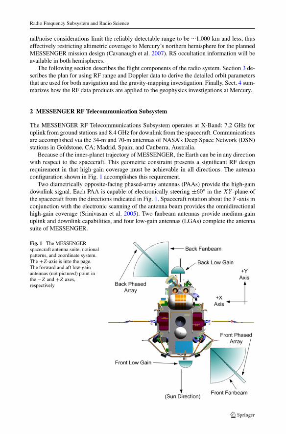
Because of the inner-planet trajectory of MESSENGER, the Earth can be in any directionwith respect to the spacecraft. This geometric constraint presents a significant RF designrequirement in that high-gain coverage must be achievable in all directions. The antennaconfiguration shown in Fig. 1 accomplishes this requirement.
Two diametrically opposite-facing phased-array antennas (PAAs) provide the high-gaindownlink signal. Each PAA is capable of electronically steering ±60° in the XY -plane ofthe spacecraft from the directions indicated in Fig. 1. Spacecraft rotation about the Y -axis inconjunction with the electronic scanning of the antenna beam provides the omnidirectionalhigh-gain coverage (Srinivasan et al. 2005). Two fanbeam antennas provide medium-gainuplink and downlink capabilities, and four low-gain antennas (LGAs) complete the antennasuite of MESSENGER.
Fig. 1 The MESSENGERspacecraft antenna suite, notionalpatterns, and coordinate system.The +Z-axis is into the page.The forward and aft low-gainantennas (not pictured) point inthe −Z and +Z axes,respectively
D.K. Srinivasan et al.
Fig
.2T
heM
ESS
EN
GE
RR
FTe
leco
mm
unic
atio
nsSu
bsys
tem
bloc
kdi
agra
m.T
wo
redu
ndan
ttra
nspo
nder
sre
lay
com
man
ds(C
MD
s)an
dac
cept
tele
met
ry(T
LM
)to
and
from
the
Com
man
dan
dD
ata
Han
dlin
gSu
bsys
tem
ofth
esp
acec
raft
.The
RF
sign
alis
rela
yed
toth
ean
tenn
asvi
aso
lid-s
tate
pow
eram
plifi
ers
(SSP
As)
and
RF
switc
has
sem
blie
s,ea
chco
nsis
ting
ofa
dipl
exer
,sin
gle-
pole
doub
leth
row
(SPD
T)
switc
hes,
and
atr
ansf
er(X
FER
)sw
itch
Radio Frequency Subsystem and Radio Science
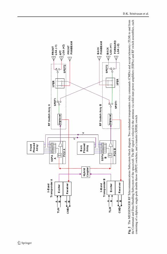
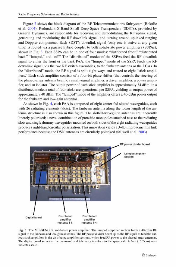
Figure 2 shows the block diagram of the RF Telecommunications Subsystem (Bokulicet al. 2004). Redundant X-Band Small Deep Space Transponders (SDSTs), provided byGeneral Dynamics, are responsible for receiving and demodulating the RF uplink signal,generating and modulating the RF downlink signal, and turning around uplinked rangingand Doppler components. Each SDST’s downlink signal (only one is active at any giventime) is routed via a passive hybrid coupler to both solid-state power amplifiers (SSPAs),shown in Fig. 3. Each SSPA can be in one of four modes: “distributed front,” “distributedback,” “lumped,” and “off.” The “distributed” modes of the SSPAs feed the RF downlinksignal to either the front or the back PAA; the “lumped” mode of the SSPA feeds the RFdownlink signal, via the two RF switch assemblies, to the fanbeam antenna or the LGAs. Inthe “distributed” mode, the RF signal is split eight ways and routed to eight “stick ampli-fiers.” Each stick amplifier consists of a four-bit phase shifter (that controls the steering ofthe phased-array antenna beam), a small-signal amplifier, a driver amplifier, a power ampli-fier, and an isolator. The output power of each stick amplifier is approximately 34 dBm; in adistributed mode, a total of four sticks are operational per SSPA, yielding an output power ofapproximately 40 dBm. The “lumped” mode of the amplifier offers a 40-dBm power outputfor the fanbeam and low-gain antennas.
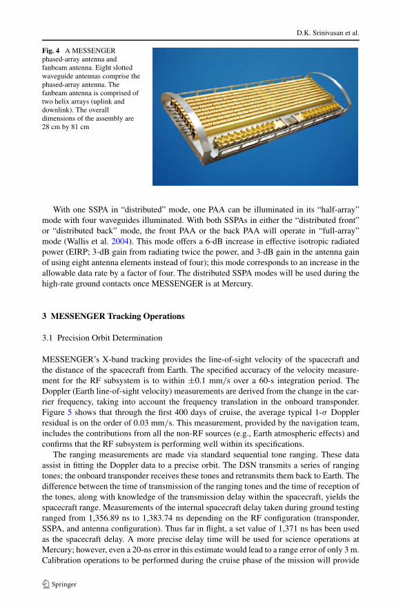
As shown in Fig. 4, each PAA is composed of eight center-fed slotted waveguides, eachwith 26 radiating elements (slots). The fanbeam antenna along the lower length of the an-tenna structure is also shown in this figure. The slotted-waveguide antennas are inherentlylinearly polarized; a novel combination of parasitic monopoles attached next to the radiatingslots and single dummy waveguides mounted on both sides of the eight radiating waveguidesproduces right-hand circular polarization. This innovation yields a 3-dB improvement in linkperformance because the DSN antennas are circularly polarized (Stilwell et al. 2003).
Fig. 3 The MESSENGER solid-state power amplifier. The lumped amplifier section feeds a 40-dBm RFsignal to the fanbeam and low-gain antennas. The RF power divider board splits the RF signal to feed the var-ious stick amplifiers in the distributed amplifier sections, which feed RF power to the phased-array antennas.The digital board serves as the command and telemetry interface to the spacecraft. A 6-in (15.2-cm) rulerindicates scale
D.K. Srinivasan et al.
Fig. 4 A MESSENGERphased-array antenna andfanbeam antenna. Eight slottedwaveguide antennas comprise thephased-array antenna. Thefanbeam antenna is comprised oftwo helix arrays (uplink anddownlink). The overalldimensions of the assembly are28 cm by 81 cm
With one SSPA in “distributed” mode, one PAA can be illuminated in its “half-array”mode with four waveguides illuminated. With both SSPAs in either the “distributed front”or “distributed back” mode, the front PAA or the back PAA will operate in “full-array”mode (Wallis et al. 2004). This mode offers a 6-dB increase in effective isotropic radiatedpower (EIRP; 3-dB gain from radiating twice the power, and 3-dB gain in the antenna gainof using eight antenna elements instead of four); this mode corresponds to an increase in theallowable data rate by a factor of four. The distributed SSPA modes will be used during thehigh-rate ground contacts once MESSENGER is at Mercury.
3 MESSENGER Tracking Operations
3.1 Precision Orbit Determination
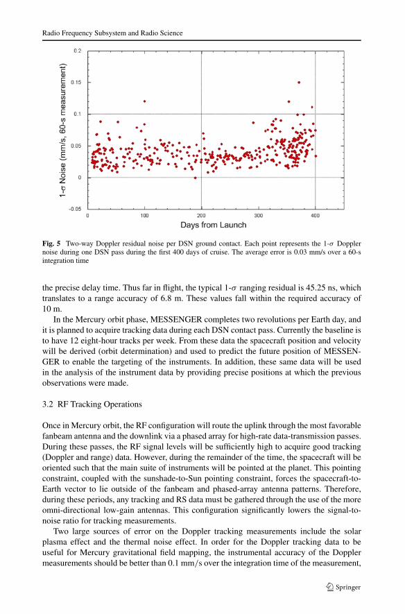
MESSENGER’s X-band tracking provides the line-of-sight velocity of the spacecraft andthe distance of the spacecraft from Earth. The specified accuracy of the velocity measure-ment for the RF subsystem is to within ±0.1 mm/s over a 60-s integration period. TheDoppler (Earth line-of-sight velocity) measurements are derived from the change in the car-rier frequency, taking into account the frequency translation in the onboard transponder.Figure 5 shows that through the first 400 days of cruise, the average typical 1-σ Dopplerresidual is on the order of 0.03 mm/s. This measurement, provided by the navigation team,includes the contributions from all the non-RF sources (e.g., Earth atmospheric effects) andconfirms that the RF subsystem is performing well within its specifications.
The ranging measurements are made via standard sequential tone ranging. These dataassist in fitting the Doppler data to a precise orbit. The DSN transmits a series of rangingtones; the onboard transponder receives these tones and retransmits them back to Earth. Thedifference between the time of transmission of the ranging tones and the time of reception ofthe tones, along with knowledge of the transmission delay within the spacecraft, yields thespacecraft range. Measurements of the internal spacecraft delay taken during ground testingranged from 1,356.89 ns to 1,383.74 ns depending on the RF configuration (transponder,SSPA, and antenna configuration). Thus far in flight, a set value of 1,371 ns has been usedas the spacecraft delay. A more precise delay time will be used for science operations atMercury; however, even a 20-ns error in this estimate would lead to a range error of only 3 m.Calibration operations to be performed during the cruise phase of the mission will provide
Radio Frequency Subsystem and Radio Science
Fig. 5 Two-way Doppler residual noise per DSN ground contact. Each point represents the 1-σ Dopplernoise during one DSN pass during the first 400 days of cruise. The average error is 0.03 mm/s over a 60-sintegration time
the precise delay time. Thus far in flight, the typical 1-σ ranging residual is 45.25 ns, whichtranslates to a range accuracy of 6.8 m. These values fall within the required accuracy of10 m.
In the Mercury orbit phase, MESSENGER completes two revolutions per Earth day, andit is planned to acquire tracking data during each DSN contact pass. Currently the baseline isto have 12 eight-hour tracks per week. From these data the spacecraft position and velocitywill be derived (orbit determination) and used to predict the future position of MESSEN-GER to enable the targeting of the instruments. In addition, these same data will be usedin the analysis of the instrument data by providing precise positions at which the previousobservations were made.
3.2 RF Tracking Operations
Once in Mercury orbit, the RF configuration will route the uplink through the most favorablefanbeam antenna and the downlink via a phased array for high-rate data-transmission passes.During these passes, the RF signal levels will be sufficiently high to acquire good tracking(Doppler and range) data. However, during the remainder of the time, the spacecraft will beoriented such that the main suite of instruments will be pointed at the planet. This pointingconstraint, coupled with the sunshade-to-Sun pointing constraint, forces the spacecraft-to-Earth vector to lie outside of the fanbeam and phased-array antenna patterns. Therefore,during these periods, any tracking and RS data must be gathered through the use of the moreomni-directional low-gain antennas. This configuration significantly lowers the signal-to-noise ratio for tracking measurements.
Two large sources of error on the Doppler tracking measurements include the solarplasma effect and the thermal noise effect. In order for the Doppler tracking data to beuseful for Mercury gravitational field mapping, the instrumental accuracy of the Dopplermeasurements should be better than 0.1 mm/s over the integration time of the measurement,

D.K. Srinivasan et al.
which will effectively vary from 10 s to several minutes. The raw Doppler measurementsare recorded at the DSN’s Central Data Recorder (CDR) at 10 samples per second. Duringpost-processing, the integration time is selected. The longer the integration time, the moreaccurate the measurement; however, with longer integration times, the measurement hasless spatial precision (e.g., during measurements taken at Mercury periapsis, the spacecraftcan move approximately 200 km during a 60-s integration). For operations at Mercury, it isdesirable to sustain integration times of no more than 10 s.
The solar plasma effect occurs when the RF signal originates in or passes through thesolar plasma with a Sun-Earth-probe (SEP) angle of less than 30° (Kinman 2002). Duringorbital operations, this condition occurs when Mercury is on the far side of the Sun. The so-lar plasma causes phase scintillations in the RF signal, thereby increasing the Doppler mea-surement error. At the X-band frequencies used on the MESSENGER mission, the Dopplermeasurement error can be approximated during the mission when MESSENGER is on thefar side of the Sun as
σV,Solar = 0.73c√
5.5 × 10⁻⁶ · [sin(θSEP)]−1.225
fcT 0.175, (1)
where σV,Solar is the Doppler measurement error (mm/s) due to the solar plasma, c is thespeed of light in a vacuum (mm/s), θSEP is the SEP angle, fc is the downlink carrier fre-quency (Hz), and T is the integration time (s). The actual error will also be a function of thecurrent solar activity level, which will be highly variable in the 2011 timeframe (the peak ofthe solar cycle).
As shown in Fig. 6, the error caused by the solar plasma is nearly always greater than0.1 mm/s for integration times of less than 60 s when MESSENGER is on the far side
Fig. 6 Doppler measurement error induced by the RF signal passing through the solar plasma at SEP anglesof less than 30° using integration times of 5, 10, and 60 s. At virtually all times during the orbital phase ofthe MESSENGER mission when Mercury is on the far side of the Sun from the Earth, this additional erroramounts to several tenths of a mm/s
Radio Frequency Subsystem and Radio Science
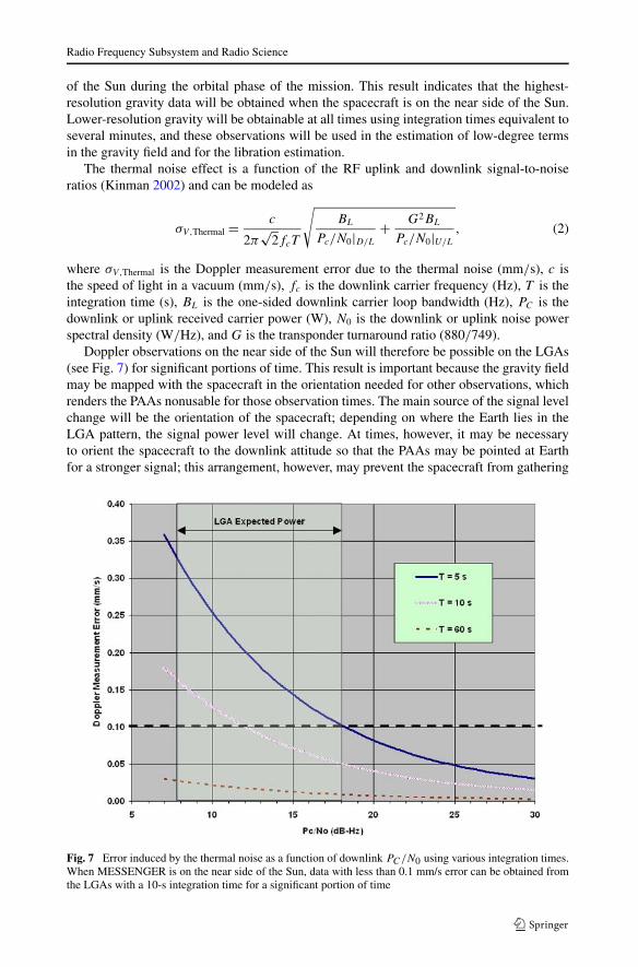
of the Sun during the orbital phase of the mission. This result indicates that the highest-resolution gravity data will be obtained when the spacecraft is on the near side of the Sun.Lower-resolution gravity will be obtainable at all times using integration times equivalent toseveral minutes, and these observations will be used in the estimation of low-degree termsin the gravity field and for the libration estimation.
The thermal noise effect is a function of the RF uplink and downlink signal-to-noiseratios (Kinman 2002) and can be modeled as
σV,Thermal = c
2π√
2fcT
√BL
Pc/N0|D/L
+ G2BL
Pc/N0|U/L
, (2)
where σV,Thermal is the Doppler measurement error due to the thermal noise (mm/s), c isthe speed of light in a vacuum (mm/s), fc is the downlink carrier frequency (Hz), T is theintegration time (s), BL is the one-sided downlink carrier loop bandwidth (Hz), PC is thedownlink or uplink received carrier power (W), N0 is the downlink or uplink noise powerspectral density (W/Hz), and G is the transponder turnaround ratio (880/749).
Doppler observations on the near side of the Sun will therefore be possible on the LGAs(see Fig. 7) for significant portions of time. This result is important because the gravity fieldmay be mapped with the spacecraft in the orientation needed for other observations, whichrenders the PAAs nonusable for those observation times. The main source of the signal levelchange will be the orientation of the spacecraft; depending on where the Earth lies in theLGA pattern, the signal power level will change. At times, however, it may be necessaryto orient the spacecraft to the downlink attitude so that the PAAs may be pointed at Earthfor a stronger signal; this arrangement, however, may prevent the spacecraft from gathering
Fig. 7 Error induced by the thermal noise as a function of downlink PC/N0 using various integration times.When MESSENGER is on the near side of the Sun, data with less than 0.1 mm/s error can be obtained fromthe LGAs with a 10-s integration time for a significant portion of time
D.K. Srinivasan et al.
science data for the remaining science instruments. The frequency at which this action willbe taken will be a balance between gathering the information for the orbit and gravity fieldinvestigations and gathering data for the other science investigations.
Because of these constraints, low-gain tracking data in the region of the periapsis may beavailable only when Mercury is on the near side of the Sun. Currently, the orbital operationsplan calls for DSN passes to be extended or added to include coverage of every periapsiswhile on the near side of the Sun, and one periapsis on the high-gain phased-array antennaevery four days (eight MESSENGER orbits about Mercury) while on the far side of theSun.
3.3 Cruise-Phase Calibration Operations
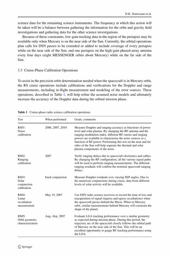
To assist in the precision orbit determination needed when the spacecraft is in Mercury orbit,the RS cruise operations include calibrations and verifications for the Doppler and rangemeasurements, including in-flight measurement and modeling of the error sources. Theseoperations, described in Table 1, will help refine the assumed noise models and ultimatelyincrease the accuracy of the Doppler data during the orbital mission phase.
Table 1 Cruise-phase radio science calibration operations
Test When performed Goals, comments
RS01:Noisecalibration
2006, 2007, 2010 Measure Doppler and ranging accuracy as functions of powerlevel and solar plasma. By changing the RF antenna and theranging modulation index, different RF carrier and rangingpowers are available to characterize the noise sources as afunction of RF power. Performing this test on the near and farsides of the Sun will help separate the thermal and solarplasma components of the noise.
RS02:Rangingcalibration
2007 Verify ranging delays due to spacecraft electronics and cables.By changing the RF configuration, all the various signal pathswill be used to perform ranging measurements. The differentranging residuals will confirm the nominal spacecraft rangingdelays.
RS03:Solarconjunctioncalibration
Each conjunction Measure Doppler residuals over varying SEP angles. Due tothe numerous conjunctions during cruise, data from differentlevels of solar activity will be available.
RS04:Lunaroccultationmeasurement
May 19, 2007 Use DSN radio science receivers to record the time of loss andreacquisition of signal (ingress and egress occultations) whenthe spacecraft passes behind the Moon. When in Mercuryorbit, similar measurements behind Mercury will constrain theshape of the planet.
RS05:Orbit geometrycharacterization
Aug.–Sep. 2007 Evaluate LGA tracking performance over a similar geometryas expected during mission phase. During this period, thetrajectory arc of the spacecraft closely follows the orbital pathof Mercury on the near side of the Sun. This will be anexcellent opportunity to gauge RF tracking performance usingthe LGA.
Radio Frequency Subsystem and Radio Science
4 Radio Science Investigations
4.1 Gravitational Field
The accuracy with which the past and future position of the spacecraft can be determined isa function of the tracking data and the orbital perturbations (which influence the motion ofthe spacecraft), of which the Mercury gravitational field is the largest source of error. Thus,in addition to solving for the position of the spacecraft around Mercury, the parameters thatdescribe the gravity field of Mercury will be estimated from the same tracking data.
The X-band transponder will provide the range-rate data between the spacecraft and aDSN ground station and will be used in a matrix of observation equations for the spacecraftstate that can be solved (Smith et al. 1993). The normal representation of the gravitationalpotential field derives from a solution to Laplace’s equation in spherical geometry, whichconsists of a finite series of spherical harmonics of the form
U(r,φ,λ) = GM
r+ GM
r
N∑l=2
l∑m=0
(a
r
)l
P lm(sinφ)(Clm cosmλ + Slm sinmλ), (3)
where U is the potential at the point (r,φ,λ), r is radial distance from the planetary centerof mass to the spacecraft, φ is latitude, λ is longitude, GM is the product of the gravita-tional constant G and the mass M of Mercury, a is the mean radius of Mercury, P lm(sinφ)
are normalized associated Legendre functions of degree l and azimuthal order m, N is thedegree and order of the solution, and Clm and Slm are the normalized spherical harmoniccoefficients that are estimated from the tracking observations. The perturbing accelerationis derived from the above equation, integrated as part of the equations of motion and nor-mal equations developed relating the observations to variables of the orbit and the gravitycoefficients Clm and Slm.
Many forces affect the motion of the spacecraft. To extract the accelerations due to Mer-cury’s gravity, these other forces must be modeled. The quality of the resulting higher-order gravity-field coefficients depends directly on the accuracy of the models of theseother forces. For Mercury, with little atmosphere and strong solar effects, the most impor-tant forces are the solar pressure, the planet reflectance pressure, and the planet’s thermalpressure. All these forces depend on the accuracy of the spacecraft surface model, and theplanet-based forces further depend on accurate knowledge of Mercury’s surface properties.The spacecraft is modeled as a series of panels, each with area, angle, emission, and ab-sorption properties that must be accurate to better than a few percent. The final spacecraftsurface model will be calibrated during the gravity-solution process by extensive iterationswith the gravity solution.
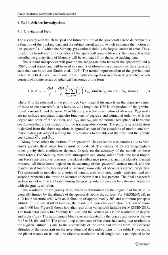
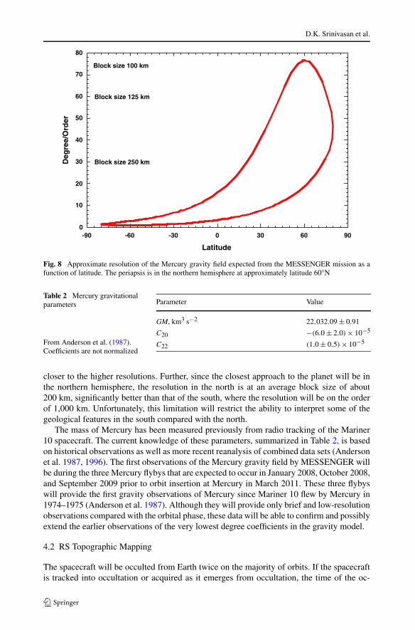
The resolution of the gravity field, which is determined by the degree l of the field, isgenerally limited by the altitude of the spacecraft above the surface. For MESSENGER, ina 12-hour eccentric orbit with an inclination of approximately 80° and minimum periapsisaltitude of 200 km at 60°N latitude, the resolution varies between about 100 km to morethan 1,000 km. Figure 8 shows how that resolution varies with latitude for MESSENGER.The horizontal axis is the Mercury latitude, and the vertical axis is the resolution in degreeand order (l,m). The approximate block size represented by the degree and order is shownfor l = 75, 60, and 30. The closed-loop appearance of the chart, indicating two resolutionsfor a given latitude, is due to the eccentricity of the orbit and results from the differentaltitudes of the spacecraft on the ascending and descending parts of the orbit. However, asthe planet rotates on its axis, the effective resolution at all longitudes is anticipated to be
D.K. Srinivasan et al.
Fig. 8 Approximate resolution of the Mercury gravity field expected from the MESSENGER mission as afunction of latitude. The periapsis is in the northern hemisphere at approximately latitude 60°N
Table 2 Mercury gravitationalparameters
From Anderson et al. (1987).Coefficients are not normalized
Parameter Value
GM, km3 s−2 22,032.09 ± 0.91
C20 −(6.0 ± 2.0) × 10−5
C22 (1.0 ± 0.5) × 10−5
closer to the higher resolutions. Further, since the closest approach to the planet will be inthe northern hemisphere, the resolution in the north is at an average block size of about200 km, significantly better than that of the south, where the resolution will be on the orderof 1,000 km. Unfortunately, this limitation will restrict the ability to interpret some of thegeological features in the south compared with the north.
The mass of Mercury has been measured previously from radio tracking of the Mariner10 spacecraft. The current knowledge of these parameters, summarized in Table 2, is basedon historical observations as well as more recent reanalysis of combined data sets (Andersonet al. 1987, 1996). The first observations of the Mercury gravity field by MESSENGER willbe during the three Mercury flybys that are expected to occur in January 2008, October 2008,and September 2009 prior to orbit insertion at Mercury in March 2011. These three flybyswill provide the first gravity observations of Mercury since Mariner 10 flew by Mercury in1974–1975 (Anderson et al. 1987). Although they will provide only brief and low-resolutionobservations compared with the orbital phase, these data will be able to confirm and possiblyextend the earlier observations of the very lowest degree coefficients in the gravity model.
4.2 RS Topographic Mapping
The spacecraft will be occulted from Earth twice on the majority of orbits. If the spacecraftis tracked into occultation or acquired as it emerges from occultation, the time of the oc-
Radio Frequency Subsystem and Radio Science
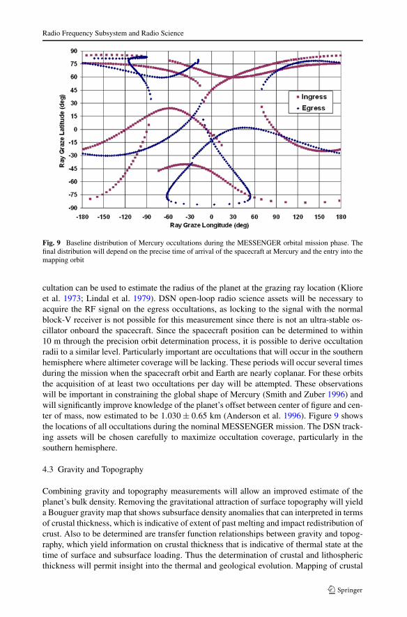
Fig. 9 Baseline distribution of Mercury occultations during the MESSENGER orbital mission phase. Thefinal distribution will depend on the precise time of arrival of the spacecraft at Mercury and the entry into themapping orbit
cultation can be used to estimate the radius of the planet at the grazing ray location (Klioreet al. 1973; Lindal et al. 1979). DSN open-loop radio science assets will be necessary toacquire the RF signal on the egress occultations, as locking to the signal with the normalblock-V receiver is not possible for this measurement since there is not an ultra-stable os-cillator onboard the spacecraft. Since the spacecraft position can be determined to within10 m through the precision orbit determination process, it is possible to derive occultationradii to a similar level. Particularly important are occultations that will occur in the southernhemisphere where altimeter coverage will be lacking. These periods will occur several timesduring the mission when the spacecraft orbit and Earth are nearly coplanar. For these orbitsthe acquisition of at least two occultations per day will be attempted. These observationswill be important in constraining the global shape of Mercury (Smith and Zuber 1996) andwill significantly improve knowledge of the planet’s offset between center of figure and cen-ter of mass, now estimated to be 1.030 ± 0.65 km (Anderson et al. 1996). Figure 9 showsthe locations of all occultations during the nominal MESSENGER mission. The DSN track-ing assets will be chosen carefully to maximize occultation coverage, particularly in thesouthern hemisphere.
4.3 Gravity and Topography
Combining gravity and topography measurements will allow an improved estimate of theplanet’s bulk density. Removing the gravitational attraction of surface topography will yielda Bouguer gravity map that shows subsurface density anomalies that can interpreted in termsof crustal thickness, which is indicative of extent of past melting and impact redistribution ofcrust. Also to be determined are transfer function relationships between gravity and topog-raphy, which yield information on crustal thickness that is indicative of thermal state at thetime of surface and subsurface loading. Thus the determination of crustal and lithosphericthickness will permit insight into the thermal and geological evolution. Mapping of crustal
D.K. Srinivasan et al.
and lithosphere thickness variations will be possible only in the northern hemisphere wherehigh-resolution gravity and topography will be obtained (see Zuber et al. 2007).
4.4 Rotational State
An orbiting spacecraft is sensitive to the long-wavelength power in the gravitational field, sothe low-degree terms in the spherical harmonic expansion of the gravitational potential arewell constrained (Kaula 1966). Of particular interest are degree-two terms, the gravitationalflattening C20 (unnormalized) and the equatorial ellipticity C22. The coefficient C22 definesthe long-wavelength gravitational shape of the equator and provides a strong constraint onthe planetary rotation rate and obliquity (Smith et al. 1993). The other phenomenon of in-terest is the libration, which is a variation in the planetary rotation rate and is manifest asan oscillation of the equatorial shape. The combination of the gravitational flattening, equa-torial ellipticity, obliquity, and libration magnitude provide a constraint on Mercury’s corestate (Peale, 1976, 1981, 1988) from the expression
(Cm
B − A
)(B − A
MR2
)(MR2
C
)= Cm
C≤ 1, (4)
where the parameters in (4) are determined from
φ0 = 3
2
B − A
Cm
(1 − 11e2 + 959
48e4 + · · ·
),
C
MR2 =[ J2
(1−e2)3/2 + 2C22(72e − 123
16 e3)] nμ
(sin I )/ic − cos I,
B − A
MR2 = 4C22,
(5)
where φ0 is the amplitude of the physical libration, i.e., the maximum deviation of the axis ofminimum moment of inertia from the position it would have had if the rotation were uniformat 1.5n where n is the orbital mean motion; ic is the obliquity of the Cassini state, the statethat Mercury’s spin axis is expected to occupy; e is the orbital eccentricity; J2 is −C20; andI is the inclination of the orbit plane to the Laplacian plane on which the orbit precessesat the uniform rate −μ. The conditions for which (4) is applicable for determination ofMercury’s core state were discussed by Peale et al. (2002).
A simulation of the MESSENGER mission scenario (Zuber et al. 2007) indicated that theconditions required for application of this method are achievable (Zuber and Smith 1997;Peale et al. 2002). The combination of the libration of the gravitational field obtained fromplanetary tracking with the libration of the topographic field obtained from the MESSEN-GER altimetry (Cavanaugh et al. 2007) may permit estimation of the viscous coupling ofMercury’s core and mantle (Zuber and Smith 1997).
5 Conclusions
While providing the mission-critical function of communication between the spacecraft andthe operations center on the Earth, the MESSENGER RF system provides for the collec-tion of Doppler and range data that are essential for precision navigation and the mission
Radio Frequency Subsystem and Radio Science
geophysics investigations. Reduction of cruise data and analyses of expected orbit opera-tions indicate that the Doppler accuracy should meet the specification of 0.1 mm/s. Thisaccuracy should resolve the spherical harmonics of Mercury’s gravitational field up to order70 in the vicinity of the periapsis and will reveal the libration of the gravity field. The RFsystem further supports the geophysics investigation by supplying planet-radii data acquiredthrough the timing of the RF occultations. These data will be used with the MLA data to mapthe topography of Mercury, data which are then combined with the gravity field to achievethe science goals related to the state and history of Mercury’s internal structure, includingthe presence and size of a liquid core, its coupling with the solid core, and the crustal andlithospheric thickness where data resolution permits.
References
J.D. Anderson, G. Colombo, P.B. Esposito, E.L. Lau, G.B. Trager, Icarus 71, 337–349 (1987)J.D. Anderson, R.F. Jurgens, E.L. Lau, M.A. Slade III, G. Schubert, Icarus 124, 690–697 (1996)R.S. Bokulic et al., IEEE Aerospace Conference, Big Sky, Mont., IEEAC paper 1370, 2004, 10 pp., CD-ROM
4-1503J.F. Cavanaugh et al., Space Sci. Rev. (2007, this issue). doi:10.1007/s11214-007-9273-4R.E. Gold et al., Planet. Space Sci. 49, 1467–1479 (2001)W.M. Kaula, Theory of Satellite Geodesy (Blaisdell, Waltham, 1966), 124 ppP.W. Kinman, JPL DSMS Document 810-005, Rev. E (2002), 124 ppA.J. Kliore, F.J. Fjeldbo, B.L. Seidel, M.J. Sykes, P.M. Woiceshyn, J. Geophys. Res. 78, 4331–4351 (1973)J. Leary et al., Space Sci. Rev. (2007, this issue). doi:10.1007/s11214-007-9269-0G.F. Lindal et al., J. Geophys. Res. 84, 8443–8456 (1979)J.V. McAdams, R.W. Farquhar, A.H. Taylor, B.G. Williams, Space Sci. Rev. (2007, this issue). doi:10.1007/
s11214-007-9162-xS.J. Peale, Nature 262, 765–766 (1976)S.J. Peale, Icarus 48, 143–145 (1981)S.J. Peale, in Mercury, ed. by F. Vilas, C.R. Chapman, M.S. Matthews (Univ. Arizona Press, Tucson, 1988),
pp. 461–493S.J. Peale, R.J. Phillips, S.C. Solomon, D.E. Smith, M.T. Zuber, Meteorit. Planet. Sci. 37, 1269–1283 (2002)A.G. Santo et al., Planet. Space Sci. 49, 1481–1500 (2001)D.E. Smith, M.T. Zuber, Science 271, 184–188 (1996)D.E. Smith et al., J. Geophys. Res. 98, 20,871–20,889 (1993)S.C. Solomon et al., Planet. Space Sci. 49, 1445–1465 (2001)D.K. Srinivasan et al., IEEE Aerospace Conference, Big Sky, Mont., IEEEAC paper 1067, 2005, 11 ppR.K. Stilwell, R.E. Wallis, M.L. Edwards, Proceedings of the IEEE International Symposium on Anten-
nas and Propagation and United States National Committee, Canadian National Committee, Interna-tional Union of Radio Science North American Radio Science Meeting, vol. 3, Columbus, OH, 2003,pp. 1030–1033
R.E. Wallis, J.R. Bruzzi, P.M. Malouf, in Antenna Measurements Techniques Association 26th Annual Meet-ing and Symposium, Stone Mountain, GA (2004), pp. 331–336
M.T. Zuber, D.E. Smith, Lunar Planet. Sci. 27, 1637–1638 (1997)M.T. Zuber et al., Space Sci. Rev. (2007, this issue). doi:10.1007/s11214-007-9265-4