

THE PUZZLER - Pump Ed 101pumped101.com/puzcomplete.pdf · The Leaking Pump Puzzler (Hydraulic Ram)...
118
THE PUZZLER © 2000 Joe Evans, Ph.D http://www.pumped101.com Pump ED 101
Transcript of THE PUZZLER - Pump Ed 101pumped101.com/puzcomplete.pdf · The Leaking Pump Puzzler (Hydraulic Ram)...

THE PUZZLER CONTENTS
Introduction 4
Basic Puzzlers
The Up And Down Puzzler (Initial & Final Velocity) 6The Restricted Pipe Puzzler (Bernoulli Principle) 9The Water Column Puzzler (Hydrostatic Paradox) 12The Sinking Float Puzzler (Buoyancy) 15The Barrel Burst Puzzler (Pascal’s Experiment) 17The False Force Puzzler (Centrifugal Force) 19The My Shaft’s Bigger Than Yours Puzzler (Torque) 22
The WK2 Puzzler (Inertia) 25The Belt Tightening Puzzler (Mechanical Friction) 28The Warranty Puzzler (Time Dilatation) 31The Water Supply Puzzler (Exponential Function) 35
Hydraulic Puzzlers
The Affinity Puzzler (The Affinity Laws) 38The Impeller Trim Puzzler (Peripheral Velocity) 40The Variable Speed Puzzler (Variable Frequency Control) 43The Crazy Impeller Puzzler (Runners) 46The Hot And Cold Puzzler (Liquid Friction & Viscosity) 49The Worn Pump Puzzler ( Axial & Radial Thrust) 52The Differing Pressure Puzzler (Eductors) 56The Corrupted Curve Puzzler (Positive Displacement Pumps Parts I & II) 60
Electrical Puzzlers
The Mumbo-Jumbo Puzzler (Motor Insulation) 68The Right Motor Puzzler (Service Factor) 72The Kill A Watt Puzzler (Reactance) 75The Starting Puzzler (Motor Starting Techniques) 78The Changing Voltage Puzzler (Three Phase Connections) 83The Distorted Wave Puzzler (Harmonics) 88The Syntax Puzzler (Boolean Logic) 92The Grounded Pump Puzzler (Corrosion Protection) 95

Application Puzzlers
The Country Boy Puzzler (Phase Generator) 99The Leaking Pump Puzzler (Hydraulic Ram) 103The Air Lock Puzzler (Siphon) 104The Drawdown Puzzler (Hydropneumatic Tanks) 106The Priming Puzzler (Centrifugal Pump Priming) 108The Suction Air Puzzler (Pipeline & System Air) 112The 4” Motor Puzzler (Tesla Meets Newton) 116
761 AHUA STREET HONOLULU, HAWAII 96819PHONE 808.536.7699 FAX 808.536.8761
www.pacificliquid.com
Introduction to the Puzzler
(Why versus What)
Memorization and learning are two very different things. As I look back on my own education, both formal and real life, most of the facts and figures that I memorized are long gone. Even today, routine details seem to slip in and out of memory based upon how often I use them. In contrast, the majority of the things that I truly learned are still with me. They may need a bit of jogging here and there but, for the most part, they can be resurrected in amazing detail. I am sure this is why I became interested in Science and, particularly, Physics. Physics is the basis for all the sciences and is at the core of Engineering. It is not merely a collection of facts, but rather a method of learning. To be sure, some degree of memorization is required but most of what we memorize is used over and over again as building blocks in the learning process. Like the random facts we deal with daily, important equations will sometimes slip away. But, their understanding remains vivid and they seem satisfied to hide quietly until they are needed again.
To me, the difference between memorization and learning is the difference between “what” and “why”. “What” tends to look for a quick and dirty fact to explain an event. “Why”, on the other hand, tends to delve deeper and attempts to explore the basics surrounding the event. Knowing that an event occurs is of limited value. Understanding why an event occurs not only explains it, but also provides us with a pathway towards the understanding of related events.
It is difficult, if not impossible, to force many adults to learn something from scratch. Regardless of how important we may think it to their long term success, it has to be a personal desire. After all, it takes far less
time and effort if we start at a higher level and memorize a group of facts that allows us to get by on a day to day basis. I know now that all we can do is to try to make it easier for those who do have the desire. And, that is the purpose of the Puzzler.
The idea for our Puzzler came from the popular Public Radio program Car Talk, hosted by originators Bob and Ray Magliozzi (the Tappet brothers). This hilariously funny, yet informative show utilizes a weekly Puzzler to provoke listeners into actually thinking about an automotive problem rather than blurting out the first thought that comes to mind. I decided that a similar format (Puzzler one week and discussion the next) would be an excellent way of getting our employees to do the same.
Although our Puzzler poses a specific question, that question is just the tip of the iceberg. Its greater purpose is to introduce a topic, theory, or principle that is basic to electromechanical machines (specifically pumps, electric motors, and their controls). Our discussion the following week not only answers the question but also explores the physics surrounding it. The whole idea is that if we gain a fundamental understanding of a topic, we will be able to apply it to a whole series of real life puzzles.
Two years and almost fifty Puzzlers later I am happy to report a modicum of success. The questions I get from several of our salespeople and engineers are broader and more open ended. Today they seem a bit more interested in why than what. And, probably most important, I hear them teaching others what they have learned.
Although there is no right or wrong way to use the Puzzler, it is organized into four groups:
Basic Puzzlers -- Those that introduce a basic physical principle or concept
Hydraulic Puzzlers -- Those specific to pumps and pumping

Electrical Puzzlers -- Those specific to electricity, motors and controls
Application Puzzlers -- General applications of pumps and motors
We hope that your organization finds these a useful educational tool. You may print them and distribute then as you wish. We ask only that you leave our logo and other identifying material in tact.
Be sure to check our page monthly for the new Puzzler. Your comments, suggestions, and ideas for future Puzzlers are welcome. Please drop me a note at [email protected].
Joe Evans, Ph.D
January, 2000
761 Ahua Honolulu, HI 96819
Phone 808.536.7699 Fax 808.536.8761www.pacificliquid.com

EL = 0 FEET
EL = 100 FEET
Arock dropped from 100 feet, water flowing from thebottom of a 100 foot tank, and a cannon ball rising to aheight of 100 feet. What do they have in common? Why?
a Solaray Company
The Up And Down Puzzler
PL&A CAD
761 AHUA HONOLULU, HI 96819

THE UP AND DOWN PUZZLER
INITIAL AND FINAL VELOCITY
Joe Evans, Ph.D
A rock dropped from 100 feet, water flowing from the bottom of a 100 foot tank, and a cannon ball rising to a height of 100 feet.
What do the above have in common? The answer is their velocities. The velocity of the rock as it strikes the ground is the same as the velocity of the water flowing from the tank. It is also the same as the velocity of the cannon ball as it exits the muzzle of the cannon. To explain this we must take a look at both the kinetic and potential energy of each and, of course, the conservation of the two energy forms. We will have to use a bit more math than usual to truly understand these relationships but, I assure you that the equations are quite simple and you will see them over and over again.
Before the rock is dropped, its kinetic energy is zero but its gravitational potential energy is mgh (where m is the mass of the rock, g is the force of gravity, and h is its height above the ground). As it strikes the ground its
kinetic energy is 1/2mv2 (where m is again the mass of the rock and v is the velocity at impact) while its gravitational potential energy drops to zero. Conservation of energy then yields:
1/2mv2 = mgh or v2 = 2gh
Solving for velocity we get:
v = √2gh = √2 x 32 ft/sec/sec x 100 ft
v = 80 ft/sec
When falling from 100 feet, the rock will be traveling at 80 ft/sec when it hits the ground (final velocity). We must, of course, assume that the rock will encounter air resistance and the friction it would cause.
Interestingly enough, the highest velocity reached by the cannon ball is also at ground level. When the powder charge is ignited, the expanding gases accelerate the ball down (or up depending upon one’s perspective) the barrel of the cannon. At the exact moment that it exits the muzzle, acceleration ceases and maximum velocity is attained. The ball will then begin the process of deceleration until it comes to a stop, reverses direction, and begins its return to the earth. If we assume, as the puzzler suggests, that the cannon ball’s initial velocity is the same as the rock’s final velocity, we can rearrange the conservation equation and solve it for height.
v2 = 2gh or h = v2/2g
h = (80 ft/sec)2 / (2 x 32 ft/sec2)
h = (6400 ft2/sec2) / 64 ft/sec2
h = 100 ft
How about that? An initial velocity of 80 ft/sec will, in fact, allow the cannon ball to attain a final height of 100 feet. Again we neglect friction.
So far we are two for two, but how about the velocity of the water exiting the bottom of the tank. The water flowing through the outlet at the bottom of the tank did not fall 100 feet. In fact, it flows from the area at the bottom of the tank! Well, according to Torricelli’s law, the water will emerge at a velocity equal to that it would have attained had it fallen through that distance.1 We can demonstrate this with the help of Bernoulli’s equation.
Assume that the water level at the top of the tank is (a) and the level of the outlet is (b). Also, since the diameter of the outlet is much smaller than that of the tank, we can neglect
1 Torricelli’s law is a form of vb2 = 2g(ya-yb). We will
derive it shortly
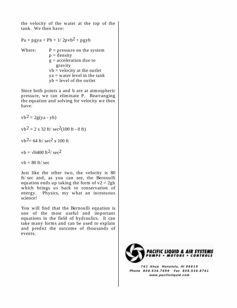
the velocity of the water at the top of the tank. We then have:
Pa + pgya = Pb + 1/2pvb2 + pgyb
Where: P = pressure on the systemp = densityg = acceleration due to gravityvb = velocity at the outletya = water level in the tankyb = level of the outlet
Since both points a and b are at atmospheric pressure, we can eliminate P. Rearranging the equation and solving for velocity we then have:
vb2 = 2g(ya - yb)
vb2 = 2 x 32 ft/sec2(100 ft - 0 ft)
vb2= 64 ft/sec2 x 100 ft
vb = √6400 ft2/sec2
vb = 80 ft/sec
Just like the other two, the velocity is 80 ft/sec and, as you can see, the Bernoulli equation ends up taking the form of v2 = 2gh which brings us back to conservation of energy. Physics, my what an incestuous science!
You will find that the Bernoulli equation is one of the most useful and important equations in the field of hydraulics. It can take many forms and can be used to explain and predict the outcome of thousands of events.
761 Ahua Honolulu, HI 96819
Phone 808.536.7699 Fax 808.536.8761www.pacificliquid.com
50 PSI40 PSI
49 PSI
50 GPM
a Solaray Company
The Restricted Pipe Puzzler
PL&A CAD
761 AHUA HONOLULU, HI 96819
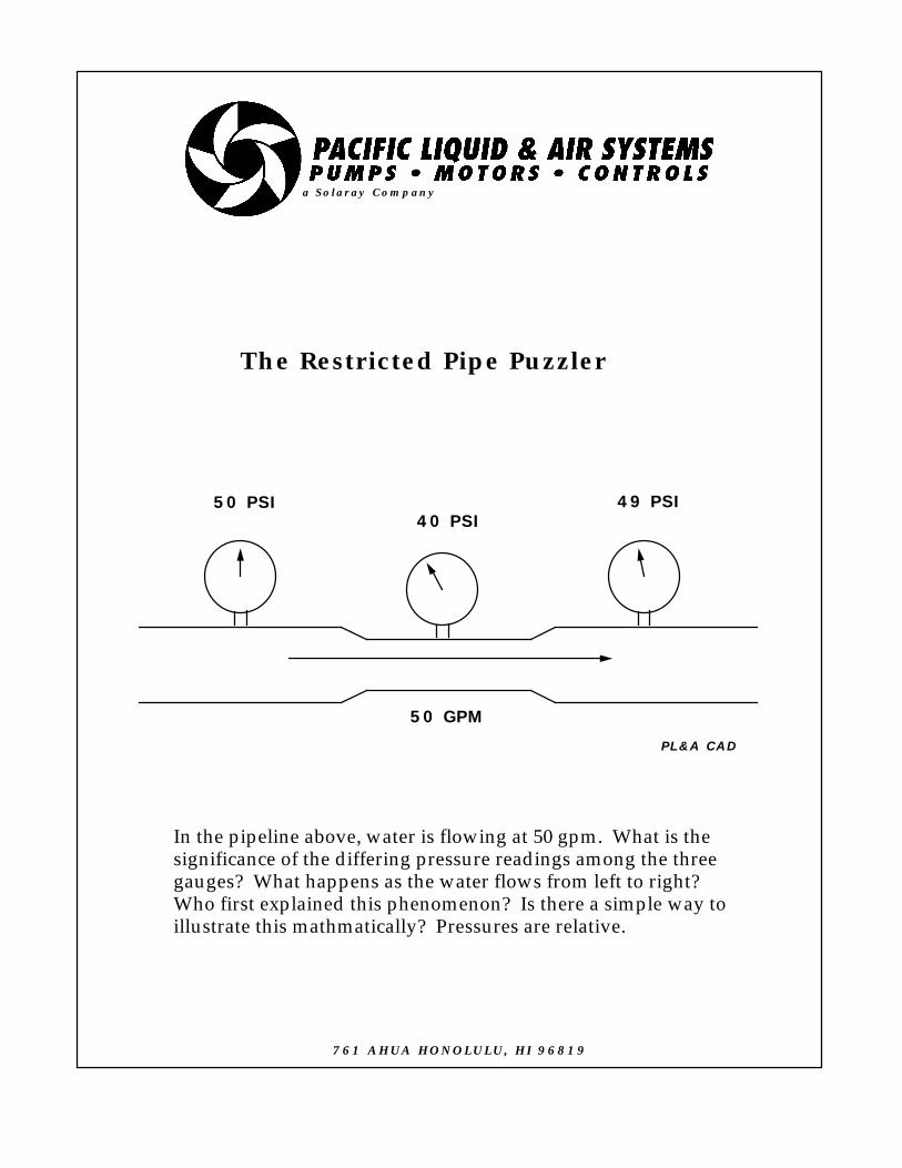
In the pipeline above, water is flowing at 50 gpm. What is thesignificance of the differing pressure readings among the threegauges? What happens as the water flows from left to right?Who first explained this phenomenon? Is there a simple way toillustrate this mathmatically? Pressures are relative.
THE RESTRICTED PIPE PUZZLER
THE BERNOULLI EFFECT
Joe Evans, Ph.D
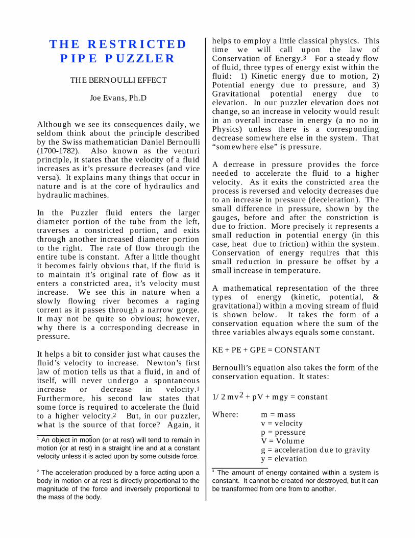
Although we see its consequences daily, we seldom think about the principle described by the Swiss mathematician Daniel Bernoulli (1700-1782). Also known as the venturi principle, it states that the velocity of a fluid increases as it’s pressure decreases (and vice versa). It explains many things that occur in nature and is at the core of hydraulics and hydraulic machines.
In the Puzzler fluid enters the larger diameter portion of the tube from the left, traverses a constricted portion, and exits through another increased diameter portion to the right. The rate of flow through the entire tube is constant. After a little thought it becomes fairly obvious that, if the fluid is to maintain it’s original rate of flow as it enters a constricted area, it’s velocity must increase. We see this in nature when a slowly flowing river becomes a raging torrent as it passes through a narrow gorge. It may not be quite so obvious; however, why there is a corresponding decrease in pressure.
It helps a bit to consider just what causes the fluid’s velocity to increase. Newton’s first law of motion tells us that a fluid, in and of itself, will never undergo a spontaneous increase or decrease in velocity.1 Furthermore, his second law states that some force is required to accelerate the fluid to a higher velocity.2 But, in our puzzler, what is the source of that force? Again, it
1 An object in motion (or at rest) will tend to remain in motion (or at rest) in a straight line and at a constant velocity unless it is acted upon by some outside force.
2 The acceleration produced by a force acting upon a body in motion or at rest is directly proportional to the magnitude of the force and inversely proportional to the mass of the body.
helps to employ a little classical physics. This time we will call upon the law of Conservation of Energy.3 For a steady flow of fluid, three types of energy exist within the fluid: 1) Kinetic energy due to motion, 2) Potential energy due to pressure, and 3) Gravitational potential energy due to elevation. In our puzzler elevation does not change, so an increase in velocity would result in an overall increase in energy (a no no in Physics) unless there is a corresponding decrease somewhere else in the system. That “somewhere else” is pressure.
A decrease in pressure provides the force needed to accelerate the fluid to a higher velocity. As it exits the constricted area the process is reversed and velocity decreases due to an increase in pressure (deceleration). The small difference in pressure, shown by the gauges, before and after the constriction is due to friction. More precisely it represents a small reduction in potential energy (in this case, heat due to friction) within the system. Conservation of energy requires that this small reduction in pressure be offset by a small increase in temperature.
A mathematical representation of the three types of energy (kinetic, potential, & gravitational) within a moving stream of fluid is shown below. It takes the form of a conservation equation where the sum of the three variables always equals some constant.
KE + PE + GPE = CONSTANT
Bernoulli’s equation also takes the form of the conservation equation. It states:
1/2 mv2 + pV + mgy = constant
Where: m = mass v = velocityp = pressureV = Volumeg = acceleration due to gravityy = elevation
3 The amount of energy contained within a system is constant. It cannot be created nor destroyed, but it can be transformed from one from to another.
If we express mass in terms of density (d) we will obtain:
d = m/V
If we substitute d for m and divide each term by v, Bernoulli’s equation takes the form of:
1/2dv2 + p + dgy = constant
Now all have units of pressure. If y does not change, an increase in velocity dictates a decrease in pressure (and vice versa) if the law of Conservation of Energy is to hold true. Bernoulli’s equation holds true for the steady, non viscous flow of all incompressible fluids.
The Bernoulli Principle is in action when an airplane flies or a baseball curves. The curved upper surface of an airplane’s wing forces the air moving over it to increase in velocity. As a result the pressure in the air near by is reduced thus allowing the higher atmospheric pressure on the bottom of the wing to push it upward. A spinning baseball thrown by a pitcher produces a similar effect. As it spins, friction causes it drag a thin film of air with it. The side of the ball spinning in the same direction as the air moving over it creates a lower pressure than the opposite side which is spinning against the flow. As a result, the ball curves toward the low pressure side.
His principle also holds true at sea. The reason that ships must not pass too closely is that the increased velocity of the water passing between them creates a low pressure area that can cause a sideways collision. For this very same reason, large docks have pilings rather than solid walls.
In the pumping arena, the Bernoulli Principle is the stuff of ejectors, eductors, impellers, and jet pumps. Over time we will cover these in some detail.
761 Ahua Honolulu, HI 96819Phone 808.536.7699 Fax 808.536.8761
www.pacificliquid.com
A B
C D
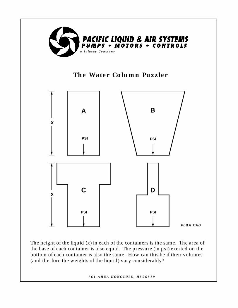
The height of the liquid (x) in each of the containers is the same. The area ofthe base of each container is also equal. The pressure (in psi) exerted on thebottom of each container is also the same. How can this be if their volumes(and therfore the weights of the liquid) vary considerably?.
X
X
PSI PSI
PSI PSI
a Solaray Company
The Water Column Puzzler
PL&A CAD
761 AHUA HONOLULU, HI 96819

THE WATER COLUMN PUZZLER
THE HYDROSTATIC PARADOX
Joe Evans, Ph.D
The pressure that a column of liquid exerts at its base depends solely upon its density and the height of the column. In some cases this is readily apparent; however, in others it can be anything but apparent.
For example, a volume of water in a column 1” X 1” X 2.31’ weighs 1 pound
(1lb=27.73in3). If this column of water were placed in the vertical position and its pressure measured at the base of the column using a gauge calibrated in pounds per square inch, we would obtain a reading of 1 PSI. If we were to increase the size of our water column to say 2” X 2” X 2.31’ we would now have a base of 4 square inches and a volume of water that weighs 4 pounds. A pressure reading at the base would still result in 1 PSI (4 lb / 4 sq in = 1 PSI). Regardless of how much we increase the cross sectional area of the column, our pressure reading will remain 1 PSI as long as the height of the water above the base remains constant.
Now suppose we were to replace the water in the above example with kerosene. Do the same rules apply? Yes they do except that the specific gravity of kerosene is only 0.8 that of water so the gauge would register only 0.8 PSI. The same holds true for liquids with specific gravities greater than that of water. In the case of a brine solution (specific gravity = 1.2) the gauge would read 1.2 PSI.
Based on this logic, it seems reasonable to expect that the pressure exerted by a volume of water measured at the base of container A of our Puzzler will depend solely upon its height above the base. We could even say the the pressure in container C is also dependent only upon the water’s height since the additional water in the expanded upper portion of the container might be supported
by its horizontal surfaces. And, in fact, these horizontal surfaces do support the additional volume of water in the container.
But what about container B? It has no horizontal surfaces to support the obviously greater volume. Will not this additional upper weight contribute to the pressure on the base? And, my God, how can that puny, contracted upper portion of container D dictate the pressure on the decidedly larger base? Lets explore.
A brick resting on the floor exerts pressure on the floor in a direction dictated by the earth’s gravitational field. It does not; however, deform due to its weight and the pressure it exerts. Liquids, unlike solids, do deform and therefore cannot exist as a geometric form without the assistance of a container. When contained, liquids exert pressure in all directions and especially in directions that are perpendicular to the walls that contain them. If we were to draw vertical lines from the outside edges of the base of container B extending vertically to the surface of the water we would create two right triangles. The weight of the additional water contained in these triangles is supported by the angled sides of the container due to the perpendicular force of the water upon them. Therefore the pressure exerted on the bottom of container B is due solely to the height of the water column.
Container D, however, is quite different than the others. Its upper portion is contracted and is missing 2/3 of the volume of the lower portion. How can it possibly exert the same pressure over the much larger area of the base?
Remember that water exerts its pressure in all directions and will therefore exert an upward pressure against the horizontal section of the container. The amount of upward pressure depends upon the height of the water above the horizontal section. By Newton’s third law of motion, the horizontal section will exert an equal pressure
downward.1 This downward pressure is equal to that which would be produced by the missing water, were it there! Yet again, the pressure exerted on the bottom is due solely to the height of the liquid above it.
Just as water is said to “seek its own level”, pressure at the base of a container of liquid will depend solely upon its density and height and is totally independent of the shape of the container. This, of course, assumes that no other outside force, other than gravity, is acting on the liquid and its container.
In conclusion lets review the term “pressure”. Normally, when our industry refers to pressure we imply “gauge” pressure or PSIG. Standard pressure gauges are calibrated to read zero at sea level. Their reading includes atmospheric pressure. “Absolute” pressure does not include atmospheric pressure and gauges calibrated in this manner will display 14.7 PSI at sea level.
1 Whenever a force is exerted on an object, the object exerts an equal force in the opposite direction.
761 Ahua Honolulu, HI 96819
Phone 808.536.7699 Fax 808.536.8761www.pacificliquid.com

The Sinking Float Puzzler
Upon cleaning the narrow sump shown above, the new maintenanceworker reported that the two floats must be waterlogged becausethey would no longer float. Another worker commented that he hadreported the same observation when he cleaned the sump severalyears earlier. Why do these defective floats continue to operate thesump pump?
a Solaray Company
PL&A CAD
761 AHUA HONOLULU, HI 96819

THE SINKING FLOAT PUZZLER
BUOYANCY
Joe Evans, Ph.D
If it looks like a float, smells like a float, and floats like a float then it probably is a float. But, if it doesn’t float it may well be something else. In the case of the sinking float Puzzler the defective floats, observed by the maintenance worker, were actually weights. How can weights determine water level and in turn start or stop a pump? Let’s see.
The switch shown in the Puzzler is known as a displacement or buoyancy switch. Its operation is based on Archimedes Principle which states that “an immersed body is buoyed up by a force equal to the weight of the fluid it displaces”. The fluid displaced is dependent only upon the volume of the body and has nothing to do with its shape or weight.
Imagine for a moment a cube, 1ft on a side and of sufficient density that it will sink when placed in water. Based upon its volume, it will displace 1 cubic foot of water. We can calculate the weight of the water displaced by the following:
1 ft3 = 7.48 gallons
= (7.48 gal / ft3) X (8.35 lb / gal)
= 62.46 lb / ft3
In other words the cube would be slightly more than 62 pounds heavier when weighed in air than it would when weighed in water. According to Archimedes then, the cube will be buoyed up by an upward force of approximately 62 pounds.
We can show that the weight of the water displaced is truly equal to the buoying force. Consider this, regardless of how deep our cube is submerged, the water pressure pressing on its bottom will always be one
foot greater than that pressing upon the top. The pressure on each of the four sides cancels itself. If this is the case, the buoyancy or net upward force exerted on the bottom of the cube is:
1 ft2 ( cube’s bottom area) = 144 in2
2.31 ft (water column) = 1 lb/in2
1 ft (water column) = 0.433 lb/in2
0.433 lb/in2 X 144 in2 = 62.35 lb
We see then that the buoyancy calculated by the pressure differential is the same as the water displaced.
Our displacement switch consists of a spring loaded switch connected to a drop wire. Attached to the wire are the two weights. When the bottom weight is only partially submerged, the combined weight of both weights pull the switch open (off). As water rises and covers the bottom weight, a portion of its weight is buoyed up. It is not enough; however, to allow the spring to pull the switch to the closed position. As water continues to rise and a portion of the upper weight is covered, the spring can overcome the force of the weights and close the switch. The pump is energized and the water level begins to fall. The reverse occurs on the way down.
By setting the elevations of the two weights, one can adjust the “pump on” and “pump off” points for the pump. A displacement switch of this type is especially useful in a narrow sump where a single, wide angle float switch may become entangled with piping or other obstructions. It is also less costly and more compact that rod type float switches designed for straight up and down travel.
761 Ahua Honolulu, HI 96819
Phone 808.536.7699 Fax 808.536.8761www.pacificliquid.com

The Barrel BurstPuzzler
The barrel shown above is four feet tall and has an average diameter oftwo and one-half feet. The pipe connected to its bunghole is thirty feettall and has an inner diameter of one inch. The barrel burst when thepipe was filled to a level of twenty-nine feet. What caused the barrel toburst? What was the weight of the water in the barrel? What was theweight of the water in the pipe? What was the pressure on the barrel'sbottom the second before it burst? Who performed this experiment?
a Solaray Company
PL&A CAD
761 AHUA HONOLULU, HI 96819

THE BARREL BURST PUZZLER
PASCAL’S EXPERIMENT
Joe Evans, Ph.D
This puzzler should have brought back memories of the “Hydrostatic Paradox” Puzzler. It is yet another reinforcement of the fact that the pressure at any point in a container of water is dependent only upon the height of the water above that point. Pressure is not at all influenced by the shape of the container.
The gentleman who performed the pipe and barrel experiment was Blaise Pascal, a seventeenth century French mathematician. With it he demonstrated that the pressure measured in the barrel did not depend upon the weight of the water in the pipe but, instead, its height above the barrel. Very simply stated:
P = hD
where:
P is pressure at a given pointh is the height above that pointD is the density of the liquid.
The barrel burst because the pressure generated by the height of the water in the pipe was greater than the barrel could withstand. Based upon the simple equation above the pressure on the barrel’s lid as it burst was 29 feet of water. Since one PSI is equal to 2.31 feet of water, the gauge pressure was 15.55 PSI (the absolute pressure was 30.25 PSI).
I asked you to calculate the weight of the water both in the barrel and in the pipe just so that you would see that the weight of the water in the pipe (even though it was 29 feet tall) was just a fraction of that in the barrel. Had the barrel been only slightly larger, it
could have accommodated the additional water, internally, without incidence. But the small diameter pipe caused the water’s height, and ultimately the additional pressure it created, to exceed the strength of the barrel.
Pascal’s studies eventually led to the important principle that bears his name. His principle states that when pressure is applied to a confined container of liquid, it is transmitted undiminished to every point in the liquid and is applied at an angle of 90 degrees to the its walls.
761 Ahua Honolulu, HI 96819
Phone 808.536.7699 Fax 808.536.8761
www.pacificliquid.com
The False Force Puzzler
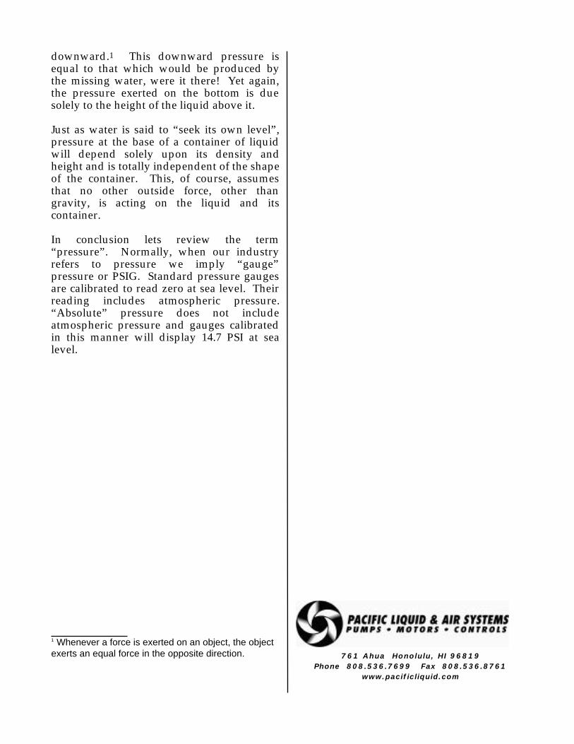
According to some folks, the can in the upper figure is drawnoutward by centrifugal force as it swings around on the string.If the string were to break, centrifugal force should propel thecan in a direction outward from the center of its circular path.But, as the lower figure illustrates, it does not! It moves in astraight line that is tangent to its original path. So what happened to that so called centrifugal force? Is this force afarce? Should we consider renaming those pumps that are soimportant to our livelihoods?
PL&A CAD
a Solaray Company
761 AHUA HONOLULU, HI 96819

THE FALSE FORCE PUZZLER
CENTRIFUGAL FORCE
Joe Evans, Ph.D
There are two schools of thought on the subject of centrifugal force. The one I tend to support views it as a false force. The other side believes that it is real. Of course they also believe that Elvis is alive and well, but don’t let that influence your own opinion.
Centrifugal force (from the Latin meaning “center-fleeing”) is an “apparent” force. In fact, its mere “existence” depends upon our own frame of reference. It is one of three important forces in physics that we refer to as “fictitious” forces. The major difference in the fictitious forces and a real force such as friction is that the real forces are based on the interactions of matter. The other fictitious forces are the Coriolis force and Newton’s simple force due to acceleration (F=ma).
The Coriolis force is a result of the earth’s rotation and is the reason projectiles fired in the northern hemisphere bend to the right and vice versa down south. During WWI the Bristish engaged the Germans in a naval battle in the Falkland islands. British gunners found that their rounds were falling well to the left of their German targets. Unfortunately their gun sights were calibrated for 50 degrees North lattitude instead of 50 degrees South lattitude. This caused their rounds to miss their targets by and amount equal to twice the Coriolis deflection. The Coriolis force also causes hurricanes in the two hemispheres to spin in opposite directions and other phenomena to numerous to mention here.
Newton’s simple acceleration is best described by Einstein’s equivalence principle. It states that we cannot distinguish between a real and a fictitious force when in the same frame of reference. Therefore a rocket ship accelerating at 32 ft/sec/sec in outer space
would create a force indistinguishable from that of gravity for an observer inside the ship.
In fact, Einstein went so far as to suggest that even gravity could be a false force. Maybe we are held to the earth because we are accelerating upward. But what about people on the other side of the earth? They cannot be accelerating upwards at the same time that we are. Einstein concluded that gravity (or any component of gravity) could be considered a false force at a single point only. This led him to suggest that the geometry of the earth and that of the universe can not be explained in Euclidean terms. Gravity in four dimensional space, where the sum of the angles of a triangle do not necessarily equal 180 degrees, can be very different indeed!
But I stray, lets get back to the Puzzler. It is a common misconception that a centrifugal force pulls outward on the can. In fact, if the string breaks, the can will move in a straight line tangent to its circular path. It does so simply because there is no centrifugal force acting on it! The only force acting on the can, prior to the string breaking, (neglecting gravity) is the centripetal force (from the Latin meaning “center-seeking”) supplied by the string. It is this centripetal force that holds the can in a circular path. Similarly, the earth’s gravity provides the centripetal force that holds the moon in a nearly circular orbit. And, it is the friction between a car’s tires and the road that provides the centripetal force necessary for it to round a curve.
Now, suppose for a moment, that someone is inside the whirling can. The can presses against his feet and provides the centripetal force that holds him in a circular path. From our frame of reference outside the can it is clear that this effect is due to inertia or the tendency of an object to follow a straight line path (as dictated by Newton’s first law).
If, however, we change our frame of reference from inertial (stationary) to that of the rotating can, we lose our original perspective and experience something quite different. We will “feel” a force that pulls our

bodies towards the bottom of the can. Although it feels very real, it is not a force at all but the effect of inertia on our bodies. Nevertheless, to observers in a rotating system, centrifugal force seems to be a very real force.
So, what about a centrifugal pump. Is its operation based on centrifugal force? Well, if so, it must operate under false pretenses!
Let us assume for a moment that a centrifugal force is a real force that it occurs only in a rotational frame of reference. Once again in our spinning can, we feel a centrifugal force pushing us against the bottom. This centrifugal force is perfectly balanced by the centripetal force offered by the can’s bottom. Therefore within the rotating system we experience no acceleration even though the rotating system, itself, is under continuous acceleration due to its circular path.. Without acceleration there can be no increase in velocity.
Now suppose that the can’s bottom opens suddenly. Will we be accelerated outward? No, we will move in the same direction the can did when the string broke and at the same velocity. So even if a centrifugal force were a real force it cannot exist without a counteracting centripetal force and thus no increase in velocity can occur. If a centrifugal force cannot increase velocity then it would not be of much use in a pump that transforms increased velocity into pressure.
Although mathematically complex, “centrifugal” pump operation is intuitively straight forward. The pump’s impeller utilizes its vanes to channel or guide a fluid through an ever increasing radius while containing it within a rotating system. This process causes the liquid to accelerate continuously as it navigates the radius and reach some maximum velocity just as it reaches the impeller periphery. It then flows into the pump’s volute where velocity is transformed into pressure.
What then should we call such a pump?
How about a radial accelerator pump or maybe a rotational inertia pump or just simply an impeller pump. Although there may be many descriptions that are more accurate, I’m afraid that we are stuck with centrifugal.
761 Ahua Honolulu, HI 96819
Phone 808.536.7699 Fax 808.536.8761www.pacificliquid.com
The My Shafts Bigger Than Yours Puzzler
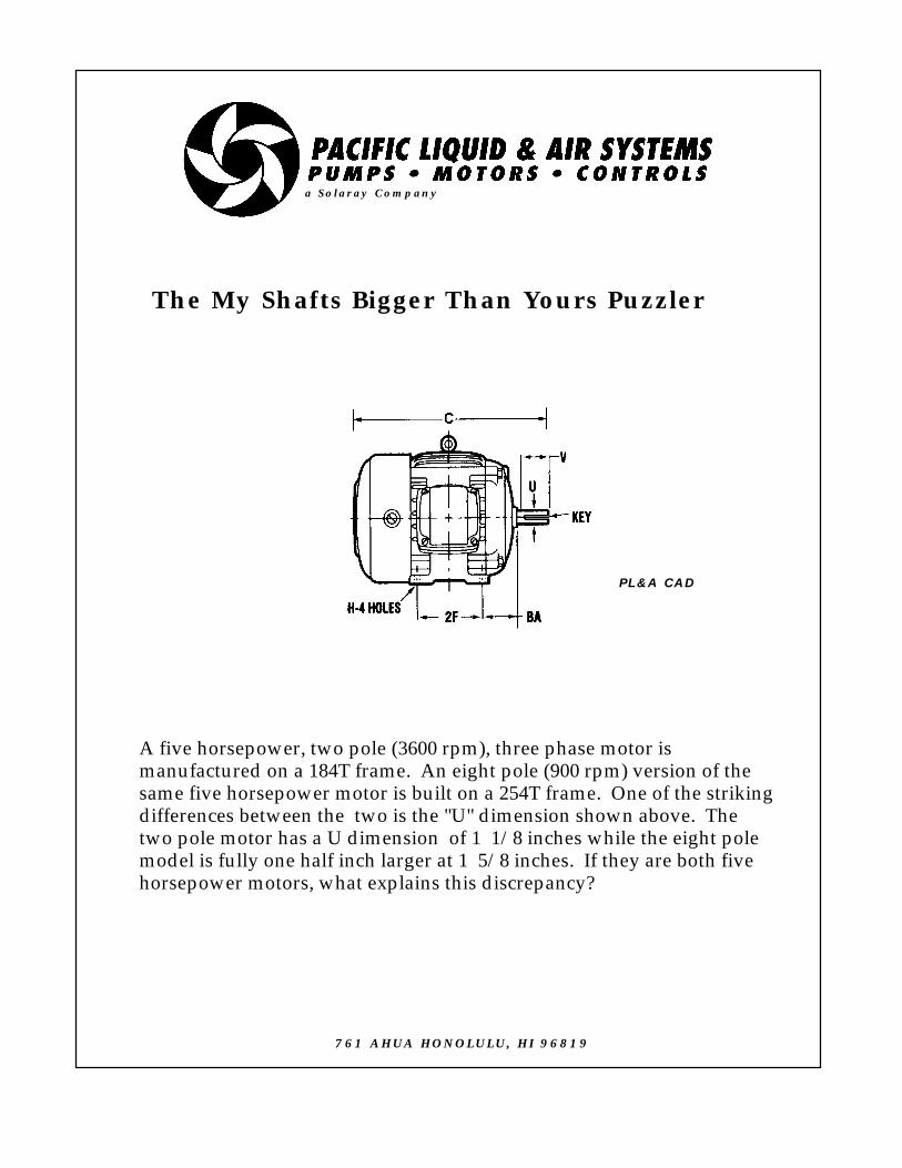
A five horsepower, two pole (3600 rpm), three phase motor ismanufactured on a 184T frame. An eight pole (900 rpm) version of thesame five horsepower motor is built on a 254T frame. One of the strikingdifferences between the two is the "U" dimension shown above. Thetwo pole motor has a U dimension of 1 1/8 inches while the eight polemodel is fully one half inch larger at 1 5/8 inches. If they are both fivehorsepower motors, what explains this discrepancy?
a Solaray Company
PL&A CAD
761 AHUA HONOLULU, HI 96819

THE MY SHAFT’S BIGGER THAN
YOURS PUZZLER
ROTATIONAL WORK
Joe Evans, Ph.D
We all know that an electric motor is a machine designed to transform electrical energy into mechanical energy so that work can be performed. Work, in a translational (linear) system, is defined as the force applied to some object multiplied by the distance it travels. In the English system force is measured in pounds and distance is measured in feet.
w = fd
If we were to lift 100 pounds to a height of 10 feet, we will perform 1000 lb-ft of work. We would perform the same amount of work if we lifted a 200 pound object to a height of 5 feet or, for that matter, a 50 pounder 20 feet. Just for the sake of comparison, work in the mks system (meter/kilogram/second) is the Joule or newton-meter and a newton is a kg-m/sec/sec. In the cgs system (centimeter/gram/second) it is the Erg or dyne-cm and a dyne is a g-cm/sec/sec. (A fig newton is not a unit of force.) Work is a somewhat unfortunate term because in order for work to be performed, we must actually move an object in a direction that is opposite of the force acting upon it. For example, if we lift a suitcase off the floor we have performed work because the force we applied overcame the force of gravity that was holding it to the floor. Carrying it across the room, however, is not work for we are not moving it in a direction that is opposite the force acting upon it. Try telling that to someone with a thirty pound suitcase in each hand. He or she may expend energy but they do no work.
The equation for work tells us how much work is done but it says nothing about how quickly it gets done. If we carry a 50 pound object up a flight of stairs 10 feet high we will perform 500 lb-ft of work. It makes no difference if we do it in five seconds or five days, the same amount of work is performed. The rate at which work is done is power. Power is equal to work divided by the time it takes to perform it.
p = w/t
In the late eighteenth century, James Watt made some major improvements to the steam engine -- improvements that made it a viable alternative to other sources of power. One of the power hungry applications in Scotland at the time was that of pumping water from coal mines. The pumps were powered by horses and Watt needed a way to relate the power of his engine to that of a team of horses. Through experimentation he determined that the average horse could lift 150 pounds to a height of 220 feet in one minute. The work performed then, is 33000 lb-ft (fd). Power or, in this case, horsepower (HP) is 33000 lb-ft/min. This rather cumbersome number is equal to 745.7 joules/sec in the mks system. One joule/sec was called a watt in his honor. One HP then is equal to approximately 746 watts. In the United States we rate a motor’s power in horsepower. In most other countries, it is the kilowatt (KW).
Torque is defined as the force that gives rise to rotational motion. It is also the result of rotational motion. Torque is equal to force times the radius through which it acts (The radius is sometimes referred to as the length of the lever arm.).
T= fr
Torque in a rotational system is analogous to force in a translational system. The straight line distance of the translational system; however, is replaced with an angular quantity.

Work then in a rotational system is:
W=Tø
where: ø is angle through which the rotating object turns
For any given HP, torque varies inversely with rotational speed. For example a 100 HP motor operating at 3600 RPM produces a torque of approximately 150 lb-ft. At 1800 RPM torque would be about 300 lb-ft and at 1200 RPM about 450 lb-ft. This is exactly what one would expect since HP (power) is the rate at which work is done. If an 1800 RPM motor is to accomplish the same amount of work in the same amount of time as one rotating at 3600 RPM, it must do twice the work per rotation. It is for this reason that the “U” dimension of the 900 RPM motor shown in the Puzzler is larger than that of the 3600 RPM model. Lower RPM motors utilize larger diameter shafts to accommodate the higher torque required to do the same amount of work in fewer rotations.
Earlier we defined horsepower as w/t and expressed it in lb-ft or watts. It can also be defined in terms of torque and speed.
HP = T x S(rpm) / 5250
We can also express torque in terms other than force and the radius through which it travels. Rearranging the previous equation we get:
T = HP x 5250 / S(rpm)
These last two equations are probably more useful in daily work than are the earlier ones.
761 Ahua Honolulu, HI 96819
Phone 808.536.7699 Fax 808.536.8761
www.pacificliquid.com

SCALE 1/4" = 3"
48"
3"
16"
3"
4"6"
6"
3"
One of our customers purchased a large, double acting air compressor at agovernment auction. Although quite old it is in excellent condition. Now hewants to make sure he purchases the proper electric motor. He has calculatedthe horsepower required by his application and added a generous percentageto cover the internal mechanical components of the pump. His remainingconcern is that of the flywheel shown above. It is quite heavy and willcertainly add significantly to the overall starting load. It is made of cast ironwhich has a density of approximately 0.26lb per cubic inch. Please calculate itsmoment of inertia (wk↑2). With this value in hand, we can be certain that themotor we supply will provide ample starting torque.
A
B
C
The WK 2 Puzzler
a Solaray Company
PL&A CAD
761 AHUA HONOLULU, HI 96819
THE WK2 PUZZLER
INERTIA
Joe Evans, Ph.D
Inertia, as defined by Sir Isaac’s first law, is the tendency of a body in motion (or at rest) to remain in motion (or at rest), in a straight line, and at a constant velocity unless acted upon by some outside force. The words “straight” and “line” limit this definition to translational (from Latin to carry across) motion.
It is possible, however, for a body to move yet not be displaced from one location to another. Thus the center of a wheel may be fixed in place so that it, as a whole, does not change position yet it may be spinning about its center. This type of motion is known as rotational motion.
Rotational motion is analogous to translational motion but it does require a slightly different perspective. In the case of translational motion we tend to think of speed or velocity in terms of miles per hour or feet per second. Furthermore we take it for granted that if one part of a body has a certain translational velocity, the rest of its parts will also. For example, if a ship’s bow is moving at ten knots its stern does also.
Things are quite different in the case of rotational motion. A point on the rim of a rotating wheel moves at a greater velocity than one closer to its center. And, at its exact center there is no motion at all. Therefore it is meaningless to talk of velocity in terms of miles per hour or kilometers per hour unless we specify some exact point. A more meaningful term is one that describes the number of complete rotations during a unit of time. Although the infinite number of points along the radius of a wheel move at various velocities, every point completes a rotation at precisely the same time. Therefore we tend to use units such as rotations per minute (rpm), degrees per
second, or radians per second to describe angular or rotational velocity.
There are, however, some instances when the velocities of the various points on a rotating wheel are important. One of those instances is when we need to know the inertia possessed by a stationary or rotating wheel.
A solid cylinder will always beat a hoop or ring down an inclined plane regardless of their respective weights or diameters. This occurs because the hoop has its weight concentrated away from its axis of rotation and thus possesses more inertia, relative to its weight, than does the cylinder. Although both objects will fall together when dropped and slide together on a frictionless inclined plane, their movement is vastly different when rotational motion is introduced.
Take, for instance, a bobsled moving across a frozen lake. Every bit of its mass, regardless of its distribution, is moving in the same direction and at the same velocity. Since its momentum is proportional to its inertia, we could say that its tendency to continue its motion is equal to its mass times its velocity (mv). Pretty straight forward but, in the case of the rotating wheel, different portions of its mass are moving at different velocities. Again momentum is proportional to inertia but, since rotation is involved, it is not as simple as the example above. Indeed, the momentum of each bit of mass in the wheel is equal to mvr where r is a particular bit’s distance from its axis of rotation. If this is the case then the wheel’s total momentum is equal to the sum of all its individual momentums. This could be quite a formidable mathematical task but fortunately, physics has derived several simple equations that allow calculation of an object’s rotational inertia. We shall use one of them shortly.
After that rather lengthy introduction lets take a look at our customer’s flywheel. The purpose of a flywheel is to even out the otherwise “jerky” operation of reciprocating machinery. It absorbs energy during one
part of a machine’s cycle while sustaining momentum during another. It accomplishes this by utilizing its inertia to maintain momentum.
If our customer’s flywheel were a solid cylinder, we could determine its weight and then compute its inertia with the following equation.
Inertia = 1/2MR2
where:
M is its mass (weight)R is its radius
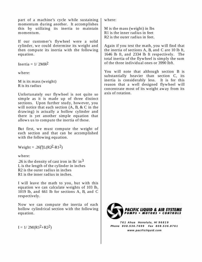
Unfortunately our flywheel is not quite so simple as it is made up of three distinct sections. Upon further study, however, you will notice that each section (A, B, & C in the drawing) is actually a hollow cylinder and there is yet another simple equation that allows us to compute the inertia of these.
But first, we must compute the weight of each section and that can be accomplished with the following equation.
Weight = .26∏L(R22-R12)
where:
.26 is the density of cast iron in lb/in3L is the length of the cylinder in inchesR2 is the outer radius in inchesR1 is the inner radius in inches.
I will leave the math to you, but with this equation we can calculate weights of 103 lb, 1019 lb, and 661 lb for sections A, B, and C respectively.
Now we can compute the inertia of each hollow cylindrical section with the following equation.
I = 1/2M(R12+R22)
where:
M is the mass (weight) in lbsR1 is the inner radius in feetR2 is the outer radius in feet.
Again if you test the math, you will find that the inertia of sections A, B, and C are 10 lb ft, 1646 lb ft, and 2334 lb ft respectively. The total inertia of the flywheel is simply the sum of the three individual ones or 3990 lbft.
You will note that although section B is substantially heavier than section C, its inertia is considerably less. It is for this reason that a well designed flywheel will concentrate most of its weight away from its axis of rotation.
761 Ahua Honolulu, HI 96819
Phone 808.536.7699 Fax 808.536.8761
www.pacificliquid.com
The Belt Tightening Puzzler
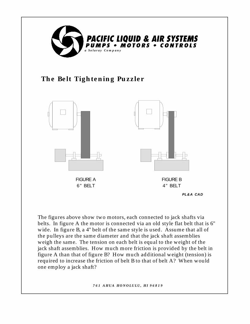
The figures above show two motors, each connected to jack shafts viabelts. In figure A the motor is connected via an old style flat belt that is 6"wide. In figure B, a 4" belt of the same style is used. Assume that all ofthe pulleys are the same diameter and that the jack shaft assembliesweigh the same. The tension on each belt is equal to the weight of thejack shaft assemblies. How much more friction is provided by the belt infigure A than that of figure B? How much additional weight (tension) isrequired to increase the friction of belt B to that of belt A? When wouldone employ a jack shaft?
FIGURE A6" BELT
FIGURE B4" BELT
a Solaray Company
PL&A CAD
761 AHUA HONOLULU, HI 96819
THE BELT TIGHTENING
PUZZLER
MECHANICAL FRICTION
Joe Evans, Ph.D
Take an orange, cut it in half, and rub the two halves together briskly. What do you get? Pulp friction. OK, OK you had to see the movie. This Puzzler should have been called a trickster rather than a puzzler because there is absolutely no difference in the friction created by either system. Why not? -- I hear you ask. Lets investigate.
Friction (from the Latin word meaning rub) is a true force. It is also the least understood of the classical forces and, unlike many concepts in physics, is an extremely complicated phenomenon. Most of our knowledge of it is empirical and our predictions about it are approximate. When a fluid flows through a pipe, the friction that arises depends upon its velocity and the surface area of the pipe. This is not the case when solids are in contact with one another. Neither the velocity of an object relative to another nor the area of contact between them influences the amount of friction produced.1
At first glance this may seem unreasonable, because surely those fat tires we see on race cars and dragsters must be there for a reason. And, isn’t that reason to increase the car’s ability to hold the road? And isn’t that ability due to friction? The answer is yes and no. Friction between the tires and the road allows a car to accelerate and corner, but that friction has nothing to do with the size of the tires.
Friction between solids occurs when their surfaces slide, or are on the verge of sliding, over one another. It depends only on the
1 Actually solid friction does vary to some degree at higher velocities.
composition of the materials in contact and the amount of force that presses them together. You will note that I said friction occurs when surfaces slide or begin to slide. A box at rest on the floor generates no friction between its bottom surface and that of the floor. If you push on it, even ever so slightly, friction arises and acts in a direction that directly opposes your push. If you increase the force behind your push, the friction acting against it increases also. Eventually, if you push hard enough, the box will begin to slide and you will probably notice that it is easier to keep it sliding than it was to get it started. Now surely Newton’s first law has something to do with this phenomenon, but if we were push the same box in a frictionless environment (zero gravity) we would find that it takes far less effort to get it started.2
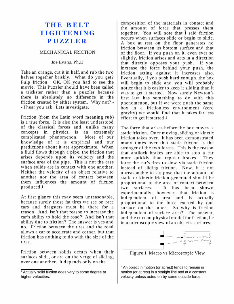
The force that arises before the box moves is static friction. Once moving, sliding or kinetic friction takes over. It has been demonstrated many times over that static friction is the stronger of the two forces. This is the reason that antilock brakes are able to stop a car more quickly than regular brakes. They force the car’s tires to slow via static friction instead of sliding friction. Now, it is not unreasonable to suppose that the amount of static or kinetic friction generated should be proportional to the area of contact between two surfaces. It has been shown experimentally; however, that friction is independent of area and is actually proportional to the force exerted by one surface on the other. So why is friction independent of surface area? The answer, and the current physical model for friction, lie in a microscopic view of an object’s surfaces.
Figure 1 Macro vs Microscopic View
2 An object in motion (or at rest) tends to remain in motion (or at rest) in a straight line and at a constant velocity unless acted on by some outside force.

When we take a microscopic look at a small portion of what appears to be a smooth macroscopic surface we see a surface that looks anything but smooth. When enlarged, the portion shown in black to the left of Figure 1 will look something like the drawing on the right. Even a polished surface is riddled with peaks and valleys throughout. Because of these irregularities, the area of microscopic contact between solids is only a small percentage of its total macroscopic surface. The maximum force of friction, then, is proportional to the microscopic area of contact, but the microscopic area is also proportional to the total macroscopic area (A) and the force per unit area (F/A) acting on its surface. Since the product of these two factors (A*(F/A)=F) is independent of the macroscopic area, we find that friction depends only on the force applied and the composition of the material itself.
Consider, for example, a ten pound rectangular box with an end area of 10 in2 and a side area of 30 in2. When it is resting on its side only a small percentage of its surface is in microscopic contact with the floor. When it is placed on its end the area of microscopic contact is increased by a factor of three because the force per unit area is three times greater. But, since the area of the end is only 1/3 that of a side, the actual microscopic contact remains the same and so does the friction.
It becomes apparent then, that the width of a tire or belt has no effect on friction as long as weight (or tension) and the material composition remain constant. The wider ones may carry a greater load, wear longer, or dissipate heat more quickly but they will slip under the very same conditions as the narrow ones.
In our Puzzler, the 4” and 6” belts are tensioned by the same amount. Even though the macroscopic surface contact is greater for the wider belt, the area of microscopic contact remains the same for both. As in the example above, the increased force per unit area acting on the narrower belt depresses its irregularities and creates an identical
microscopic area. Therefore the friction created by the two systems is equal.
Jackshafts can be employed in mechanical drive systems for several reasons. Those shown in our Puzzler are used to relieve motor bearings of large overhung loads. They can also be used to match the speed of the driver to that of the driven machine. Another application is the use of a single driver to supply power to several machines. Turn of the century manufacturing plants and machine shops used jackshafts, that often extended the entire length of the plant floor, to power dozens of rotating machines with a single steam engine.
761 Ahua Honolulu, HI 96819
Phone 808.536.7699 Fax 808.536.8761
www.pacificliquid.com

a Solaray Company
PL&A CAD4 LIGHT YEARS
SPLAT
0.97C
IPS
CHICAGO
The Warranty Puzzler
A distributor friend of ours has an interesting warranty problem. It seems that he won acontract to supply several large lineshafts, complete with fusion reactor drivers, to the planetSplat. The pumps were specially designed for remediation of dihydrogen monoxide, acorrosive chemical found to be leaching into many of the planet’s subterranean aquifers. Splat,formed several hundred million years ago when a asteroid collided with a swarm of matinginsects, is in the Alpha Centauri system about four light years, as the crow flies, east ofChicago. The distributor delivered the pumps personally via his carrier Intergalactic ParcelService (IPS), a company known for its speedy delivery vehicles and the habit of parking themwherever they can cause the most congestion. The vehicle he chartered is not the speediest inthe fleet but does maintain a respectable velocity of 0.97C. Upon installation, one of the pumpsproved defective and was returned to Chicago on the same vehicle when it left Splat severaldays later. The defect was traced to a Spam based lubricant made in the Nation Of Hawaii,once a part of the USA but currently aligned with Bosnia. Although this new alliance has beenof limited economic value, both have benefited from an exchange of excess of vowels andconsonants. But I stray. Upon his return to Chicago with the defective pump, the distributorfiled a warranty claim with its manufacturer, Worthlesston Pumps, a division of the Mafia runItalian consortium Upper Uranus Industries. Initially UUI took a defensive position andclaimed that an Indigenous Affirmative Action Program gave them little control over thequality of outsourced components. But, after researching the serial number, they reported thatit really didn't matter because the warranty had expired. Their records indicate that the pumpwas purchased over eight years ago. The distributor is relatively sure that it was purchasedabout two years ago but he is certain it was within the three year warranty period. Can youhelp solve this dispute?
761 AHUA HONOLULU, HI 96819

THE WARRANTY PUZZLER
TIME DILATATION
Joe Evans, Ph.D
This Puzzler is just for fun. One of the comforting things about our profession is that almost every thing we do is rooted in basic, common sense physics. Although it can get a bit complex sometimes, it seldom strays from classical mechanics and electricity. When we enter the realm of super velocity, however, the rules can be anything but common sense.
Einstein once said that common sense is composed of the prejudices we acquire prior to the age of eighteen. I believe that it can be quite a bit more than that, but he did have a point. Often, what we have learned through experience can and does prejudice our view when we are confronted with something that is outside our current area of understanding.
Take, for example, the measured velocity of light in a vacuum. Einstein postulated that it is always constant regardless of the motion of its source. Now this seems to conflict with the findings of Galileo and Newton, and it certainly goes against our common sense view of the situation. Surely the velocity of the beam of light emitted by an automobile’s headlight is greater when traveling at sixty miles per hour than when sitting at a stop sign. After all, if one throws a baseball while standing in a moving train car its velocity, as measured by an observer standing by the track, will appear to be the sum of the two velocities. In other words the observed velocity will be the velocity of the ball relative to the train plus the velocity of the train relative to the track. It would seem that the same should be true for a light beam. But, it turns out that it is not and, as difficult as it may be to accept, it is not true in the case of the baseball either.
In simple Newtonian terms the ball’s (or the light’s) velocity will be V = V1 + V2 where V is the total velocity relative to the observer, V1 is the velocity of the ball relative to the train, and V2 is the velocity of the train relative to the track.
The Einsteinian view, shown below, is mathematically quite different and takes into account the velocity of light (C) and its effect on our measurement of an event.
V = V1 + V2 / (1 + (V1V2/C2))
If you test the simple algebra of the two equations above, you will find that Newton views the total velocity simply as the sum of the individual velocities while Einstein would find it to be a wee bit less. For normal velocities Einstein’s V will always be an extremely small amount less than the sum. For higher velocities, the difference becomes much greater. In fact, if either or both of the velocities equals C, Einstein’s equation reduces to V = C. Therefore no two velocities, when added together can exceed the measured velocity of light.
I find this comparison of Newtonian and Einsteinian motion to be a classic example of the usefulness of the simpler Newtonian laws as they apply to everyday life. Although Einstein is absolutely right and Newton is absolutely wrong, his approximations are typically all we need. At the velocities we normally encounter the inaccuracies are minuscule. As far as we are concerned, the velocity of water exiting a pump’s impeller is the sum of the suction velocity and that imparted on the liquid by the impeller (even though we know that it is somewhat less). But, unfortunately, our Puzzler forces us to forsake Newton in this case. We will need Einstein’s help if we are going to solve our distributors dispute with that certain Italian consortium.
The Puzzler tells us that our distributor’s round trip from Chicago to Splat covers a distance of eight light years (the distance light travels at 186,000 mi/sec in a years time).
Since his transport travels at 0.97C (which is less than the speed of light) his travel time, neglecting a few days on Splat, should be 8.25 years. This period of time appears to support UUI’s claim that the three year warranty had, indeed, expired. But is this really an open and shut case? The distributor claims that the pumps are well within the warranty period and he has proof to back up his claim. The atomic clock (complete with optional calendar function) on board the IPS transport was used to log the departure and arrival dates for both legs of the trip. The log clearly states that the round trip took just over two years. But how can this be if light itself requires four years to complete just one leg?
It turns out that this discrepancy is due to something called time dilatation (slowing down) a phenomenon proposed by Einstein in his 1905 paper on special relativity. Now, it is not within the scope of the Puzzler to discuss this theory in detail, but I hope that our quick brush with it will tempt you toward further reading. Unfortunately, we have been conditioned to believe that his work is beyond the comprehension of most normal people but I can assure you that it is not. The special theory is about uniform motion. His general theory, which deals with non-uniform motion, was published about ten years later. Our Puzzler touches on part of it also.
Until the early twentieth century it was generally accepted that light was a pure wave form. If these waves traveled through space (a vacuum) there had to be something present in that vacuum that supported their propagation and transmission. That something, however, could not be detectable because, if it were, it would interfere with the movement of the planets and stars. This something was called ether, a frictionless “gas” that was considered to be at total rest with respect to the universe. Its sole purpose was to transmit light waves and gravitational forces.
Since the earth rotates at a constant velocity in this motionless ether, there should be a sort of ether “wind” (even though you could
not feel it) flowing across the earth’s surface. It seemed reasonable that light waves traveling with the ether wind would be measured as faster than those traveling against the wind. The velocity difference, of course, would be the rotational velocity of the earth. In 1886 Michelson and Morley designed an experiment that attempted to measure this difference in the velocity of light relative to the ether wind. Although their instrument was sensitive enough to measure the expected minute difference, they were unable to detect any at all.
In 1893 the Irish physicist, George Fitzgerald, proposed an explanation for the failure of their experiment. He suggested that all objects become shorter in the direction of their absolute motion and at a given velocity an object’s length (or the distance between two objects) will be some invariable ratio to its length (or distance between) when at rest. Fitzgerald expressed this ratio as:
L = L0 √ 1-(V2/C2)
where L is the moving length, L0 is the at rest length, V is the velocity of the object, and C is the velocity of light in a vacuum. This contraction in length explained precisely why Michelson and Morley could detect no difference in the velocity of light regardless if it was moving with or against the ether wind. Again if you test the algebra of the Fitzgerald equation, you will find that length contraction is extremely small at normal velocities. But at higher velocities it becomes significant and when V is equal to C, L becomes zero. In other words, at the velocity of light, an objects length and the distance between them (including the entire universe) becomes zero. A few years later the Dutch physicist, Lorentz, used Fitzgerald’s work to show that the mass of a body also increases with velocity and in the same proportion to its decrease in length.
It just so happens that Einstein concluded that the very same ratio applies to the passing of time. Since time is measured by some form of periodic motion (ie a pendulum, the vibration of an atom, rotation of the earth,

etc), these motions themselves must also be affected by increasing velocity. If we substitute time for length in Fitzgerald’s equation we can compare the time lapse of an object in motion, at some velocity, to that of one at rest.
At a velocity of 0.97C the Puzzler’s transport will require just over a year (as measured from our vantage point here on earth) to travel the same distance light travels in a single year. If, however, our vantage point changes to that of the transport, we will measure a very different time lapse. According to the Fitzgerald ratio, we will observe time passing at a rate that is only one quarter that observed on earth.
t = t0 √ 1 - (V2/C2)* = t0 √ 1 - (.97C2/C2)*
t = t0 √ 1 - 0.94* = t0 √ 0.06* = 0.25 t0
And this, of course, accounts for the fact that the transport’s log showed just over two years for the entire round trip.
But wait a minute. If our transport traveled, in just a little over two years, the same distance it takes light eight years, it must have been traveling at almost four times the speed of light! But it did not. From an earth frame of reference, Splat is four light years away, but in the transport’s frame of reference the Fitzgerald contraction comes into play. At a velocity of 0.97C the distance between Chicago and Splat (and that of the entire universe) is shortened substantially. So the transport can make the round trip in just over two years without exceeding the speed of light.
Light, from its own frame of reference, could have made the same trip (or for that matter any trip) in no time at all. Although light travels at a finite velocity, it is high enough to cause distance (and therefore time) to contract to zero. As far as light is concerned, the entire universe is infinitely thin!
The contraction of time due to an increase in velocity is a challenging one because, in our everyday lives, we deal in terms of absolute
time. I can assure you that it will take many readings and much thought to come to grips with these concepts. If you would like to do some additional reading on the theories of relativity and special relativity, a very good starting point is:
I saac Asimov, UNDERSTANDING PHYSICS (1966), BARNES & NOBLE BOOKS (1993)
* My square root sign is not adjustable. It should encompass the entire equation.
761 Ahua Honolulu, HI 96819Phone 808.536.7699 Fax 808.536.8761
www.pacificliquid.com

a Solaray Company
PL&A CAD
The Water Supply Puzzler
761 AHUA HONOLULU, HI 96819
Population: 10,000Well Capacity: 3.9 MGDElevated Storage: 900,000 GalPumping Capacity: 3.8 MGDCurrent Usage: 1.9 MGD
Town of Groin MO
The small town of Groin has an excellent source of water. The water board saysthat their treatment and delivery system is loafing along at about half of itsmaximum capacity. Since increased demand by the current population runs onlyabout 2% per year, they feel comfortable that the current system should be morethan adequate for many years to come.
The city council is still a bit concerned. Groin seems to be growing in popularitywith many families who are tiring of the crowding in St. Louis which is about thirtymiles away. Their survey data indicate that its population could grow by anaverage of 5% per year. If we assume that water usage in the future will be directlyproportional to the number of residents, how long will their existing system last?
What if our assumption of water usage is incorrect? After all, as a populationgrows more than just individual consumption must be satisfied. With a greaternumber of residents, more swimming pools will be required and more parks mustbe irrigated. Suppose, for a moment, that water usage increases at a rate that is10% greater than that of the population growth rate. How long will the currentsystem last under these conditions?

THE WATER SUPPLY PUZZLER
THE EXPONENTIAL FUNCTION
Joe Evans, Ph.D
The effect of change, whether it be in the growth of a population or the attraction due to some natural force, can sometimes be difficult to fully comprehend. On the other hand, changes that occur in some straight forward proportion are easy to grasp
Consider, for example, the following changes. We seem to work half again as many hours as we used to and it appears there are twice as many tasks to accomplish. Computers are ten times faster than they were just a few years ago yet only one third as likely to crash. The flow created by a centrifugal pump is directly proportional to its rotational speed.
These descriptions of change are readily comprehendible because we can easily visualize their effect. This is not necessarily the case when change is continuous and steady. When change occurs at a steady rate, we refer to it as exponential. The affinity laws, for instance, tell us that the head developed by a centrifugal pump varies as the square of a change in speed while horsepower varies as the cube. We think we understand the effect of these exponents, but do we really comprehend their magnitude?
The following exercise will introduce you to their instatable nature. Take a plain sheet of 8.5 X 11 inch copier paper and fold it in half. Continue folding it in this fashion until you have completed ten folds. Go ahead and do it now before reading any further.
Now, if you somehow knew that this exercise was an impossible task, you may already have a good understanding of the exponential function. If, however, you
forged ahead on faith alone, you should definitely continue reading.
What you probably noticed as you folded the paper was that it went pretty smoothly for the first four or five iterations. The sixth fold was more difficult and the seventh was virtually impossible. In attempting to fold the paper back upon itself you were witnessing the exponential function in action. Each time you folded, the number of layers and therefore its overall thickness doubled. After one fold there were two layers of paper
(21), after two folds there were four (22),
after three folds - eight layers (23), and so on.
Had you been able to fold it nine times (29) there would be 512 layers -- about the thickness of a standard ream of copier paper.
That tenth fold (210) would have produced the equivalent of two reams! All in all, your single sheet would result in a pile four inches thick!
If you could continue this process for another
15 folds (a total of 25 (225)) the result would be a stack a little over one mile high! And, if
you could complete 50 folds (250) a 71 million mile monster would appear before you!
Now, do not worry about your mental powers if you actually tried to fold the sheet of paper. When confronted with such an apparently simple task, most of us will do the same thing. Let it be a lesson though. Numbers can fool us, and especially when they are presented in a way that is not intuitively obvious.
An important component of exponential change is something called doubling (or halving) time. Doubling time is the time it takes something growing at a steady rate to double in size. The reason it is so important is because doubling (or halving) is an easy concept for us to comprehend where as the exponent itself may not be. The following simple equation allows us to calculate doubling time based upon some steady rate of growth

Doubling Time = 70 / %Growth Rate
Here is an example all of us can appreciate. The doubling time equation predicts that an investment returning 10% annually will double in value every seven years. This, of course, is known as compound interest and represents interest earned not only on the principle but on the interest also.
In our Puzzler, the town of Groin was thought to be growing at a rate of 5% each year. Upon first glance this doesn’t seem unusually large. After all at 5%, will it not take 20 years for the population to increase by 100%? Well, if a population grew in the same manner as does simple interest, it would take that long. But, exponentially speaking, this 20 year estimate is a bit off the mark.
Based upon the exponential function and the doubling time equation above, the population will double every 14 years. Think about it, every 14 years the requirement for most municipal services will double! Twice as many police & firemen, a doubling of sewage treatment capacity, twice as much garbage, and at least double the water currently consumed.
But wait a minute. In addition to the population growth, the water board estimates that the current population’s water needs will increase by 2% each year. This increase by itself suggests a 35 year life for the existing treatment and delivery system. But when combined with expected growth, demand will increase by 7% annually and reduce the remaining life of the existing system to only 10 years! And if our prediction, that water usage is actually 10% greater than the population growth rate, is correct the remaining life of the system will be reduced to just 9 years.
It becomes pretty easy to see the importance of doubling time. It takes some pretty “fuzzy” numbers and puts them in a perspective we can readily comprehend. Planning and building for growth is an
ongoing process. In the case of Groin, nine or ten years is not a long time especially when one considers the services that must be scaled up to meet the needs of a growing population. Doubling time is a tool that can help portray these exponential changes in a more understandable format.
761 Ahua Honolulu, HI 96819Phone 808.536.7699 Fax 808.536.8761
www.pacificliquid.com
The Affinity Puzzler
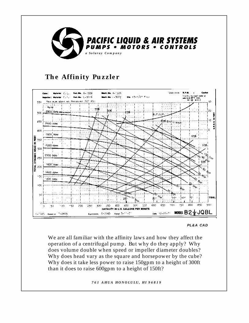
We are all familiar with the affinity laws and how they affect theoperation of a centrifugal pump. But why do they apply? Whydoes volume double when speed or impeller diameter doubles?Why does head vary as the square and horsepower by the cube?Why does it take less power to raise 150gpm to a height of 300ftthan it does to raise 600gpm to a height of 150ft?
a Solaray Company
PL&A CAD
761 AHUA HONOLULU, HI 96819

THE AFFINITY PUZZLER
THE AFFINITY LAWS
Joe Evans, Ph.D
The affinity laws allow us to predict a centrifugal pumps operational characteristics when its rotational speed or impeller diameter is modified. They are valid only under conditions of constant efficiency. For example when an full size impeller, designed for a particular volute, is trimmed pump efficiency is decreased. This decrease is caused by increased recirculation of the pumped fluid between the impeller and volute. Since the efficiency of the two impeller trims is not constant, the affinity laws become approximations and cannot be relied upon to predict, with complete accuracy, the outcome. The same holds true for a speed change. Although not nearly as severe as an impeller trim, a change in speed can alter both pump efficiency and the accuracy of the law’s predictions.
Be aware that most composite pump curves show efficiencies that are obtained with the maximum impeller diameter or rotational speed. Reducing either will reduce stated efficiency. None the less, the affinity laws are usually a reliable predictor when small impeller trims (15%) or moderate speed reductions (50%) occur within the same pump model.
FLOW VARIES DIRECTLY WITH A CHANGE IN SPEED OR DIAMETER
Flow changes in a centrifugal pump much as it does in a positive displacement pump. A piston pump whose cylinder contains one gallon of water at the bottom of its stroke and zero gallons at the top, will provide one gallon for each complete stroke or rotation. At 120 RPM its flow rate will be 120 GPM. If we reduce its speed to 60 RPM its output is also be reduced and the resulting flow will be 60 GPM.
A somewhat similar action occurs in a centrifugal pump. The flow capacity of an impeller depends upon its design (type, eye size, vane size, etc), its diameter, and its speed. If we hold all other factors constant and reduce the pump’s speed in RPM by one half we will, theoretically, halve the rate at which it discharges fluid from its impeller vanes. But why is flow rate reduced when an impeller is trimmed? After all speed remains the same.
This apparent discrepancy is rooted in our reference to speed. In the case of a positive displacement pump we speak of speed in terms of rotations per minute or strokes per minute. Although we can refer to centrifugal pump speed in rotations per minute, it is often more convenient to refer to the peripheral speed of the impeller. When we do so we combine the effects of RPM and diameter into a single unit. It is this unit (usually feet per second) that governs both rate of flow and head.
Peripheral speed (or more properly velocity) is the distance that a point on the outer most rim (periphery) travels in a unit of time. For example, an impeller with a diameter of 10” has a circumference of 31.42” (C=2πr). Therefore a point on the periphery will travel 31.42” or 2.62’ in one rotation. At 1800 RPM its velocity is 4716 ft/min or 78.6 ft/sec. A change in either diameter and/or RPM will affect the resulting velocity. And, it is this velocity (not speed) to which flow is directly proportional.
HEAD VARIES AS THE SQUARE OF A CHANGE IN SPEED OR DIAMETER
The affinity laws tell us that if we reduce the rotational speed of an 8” impeller from 1800 RPM to 900RPM the resulting head will be just one quarter that of the original head.
900 RPM / 1800 RPM = 0.5 (0.5)2 = 0.25
Lets take a look at why this is true. If we convert the two different rotational speeds of

our 8” impeller to peripheral speed we can easily compare their resulting heads.
Circumference = 2πrCircumference = 2 x 3.1416 x 4”Circumference = 25.13” or 2.09’
Velocity @ 1800 RPM = 2.09’ x 1800Velocity = 3762 ft/min or 62.7 ft/sec
Velocity @ 900 RPM = 2.09’ x 900Velocity = 1181 ft/min or 31.35 ft/sec
We can use the falling body equation to determine the theoretical heads that are produced by these two velocities.
v2 = 2gh h = v2/2g
h = (62.7 ft/sec)2 / 2 X 32 ft/sec2h = 61.4’ @ 1800 RPM
h = (31.35 ft/sec)2 / 2 X 32 ft/sec2h = 15.35’ @ 900 RPM
The results are just what the affinity law predicted. The head produced at 900 RPM is 15.35’ or just one quarter that produced at 1800 RPM. Since g does not change near the earth’s surface, h will vary as the square of velocity.
HORSEPOWER VARIES AS THE CUBE OF A CHANGE IN SPEED OR DIAMETER
In order to see why horsepower varies as the cube of a change in speed we have to convert flow and head into a more usable format. Horsepower is a rating we use to measure work done per unit time (See the Rotational Work Puzzler). In the English system it is equivalent to 33000 lbft/min.
The composite curves in the Affinity Puzzler indicate that the pump can deliver 600 GPM @ 150’ @ 2000 RPM and 600 GPM @ 400’ @ 2800 RPM. This represents an increase in speed of 1.4. If we convert these flows and heads into work (where w=fd) we have:
600 GPM x 8.35 lb/gal x 150’ = 751,500 lbft/min
600 GPM x 8.35 lb/gal x 400’ = 2,004,000 lbft/min
Converting these to horsepower we obtain:
(751500lbft/min)/(33000lbft/min/HP)= 22.77 HP @ 2000 RPM
(2004000lbft/min)/(33000lbft/min/HP)= 60.72 HP @ 2800 RPM
The affinity law predicts that horsepower will
increase by (1.4)3 or 2.74 when speed is increased from 2000 to 2800 RPM. When we multiply 22.77 HP by 2.74 we get 62.4 HP which is a good approximation of the actual horsepower.
You probably noticed that the horsepower requirements computed above are substantially less than those indicated on the composite curve. This is an important observation and points out the role pump and motor efficiency play in the overall application. Our computed numbers assume that both the pump and motor are 100% efficient. If you divide our computed numbers by the pump efficiency at each of the two operating points, our numbers will agree closely with the published ones for the pump. Of course motor efficiency is not 100% either, so the efficiency of the entire machine (pump & motor) will be even less.
761 Ahua Honolulu, HI 96819
Phone 808.536.7699 Fax 808.536.8761www.pacificliquid.com

100'
1800 RPMPUMP
KEROSENE
KEROSENE
An underground tank supplies kerosene to a centrifugal pump at groundlevel. The pump, in turn, supplies another tank that is 100 feet above itsdischarge. Ignoring friction within the system, what diameter must thepump's impeller be if it is rotating at1800 rpm? Also what pressure will beindicated by the two gauges?
The Impeller Trim Puzzler
10'
a Solaray Company
PL&A CAD
761 AHUA HONOLULU, HI 96819

THE IMPELLER TRIM PUZZLER
Joe Evans, Ph.D
This Puzzler encompasses several of the concepts that have been introduced by previous Puzzlers. The clues you were given were designed to make you think about things a little differently than you might normally.
In the Puzzler, the supply tank is below ground so we know that that a suction lift condition exists. But can the pump lift kerosene? A quick check of its vapor pressure indicates a 10 foot lift at sea level and ambient temperature will not impose a problem.
We also know that the discharge head required is 100 feet. By adding the suction head and the discharge head we find that the total head required is 110 feet. Now, all we need to do is to calculate the impeller diameter required to generate 110 feet of head.
The first step, in determining diameter, is to find the initial velocity necessary to propel an object to a height of 110 feet. Just like the cannon ball in an earlier puzzler, the velocity of water as it leaves the impeller’s vane determines the height to which it will rise.
Solving our well used conservation equation for velocity we have:
v2 = 2gh or v = √2gh*
v = √64 x 110 or v = 84 ft/sec
The periphery or outside edge of the pump’s impeller must have a rotational velocity of 84 ft/sec in order to provide the same velocity to the water that exits its vanes. Since our 1800 RPM motor rotates 30 times each second, a point on the impeller’s periphery must travel 2.8 feet (84/30) or 33.6 inches during each rotation. 33.6 inches, then, is the
circumference of the impeller. Simple geometry can now lead us to the answer we desire, its diameter.
c = πd or d = c/π
d = 33.6/3.14 = 10.7”
Therefore an impeller approximately 10.75 inches in diameter, rotating at 1800 RPM will generate 110 feet of head.
Had the fluid in our example been water, the pressure indicated by the gauge on the discharge side of the pump would be about 43 PSI (100/2.31). But the liquid is not water, it is kerosene which has a specific gravity of 0.8 that of water. Therefore the discharge gauge will indicate about 34 PSI even though the head in feet is 100.
The gauge on the suction side of the pump will not indicate a pressure, but rather a vacuum. Again, were we pumping water, a vacuum gauge calibrated in feet of water would indicate 10’ (the distance from the center line of the pump’s suction to the water level). One calibrated in inches of mercury would indicate about 9”. But, again, the liquid is kerosene with a specific gravity of 0.8, so the readings will be 8’ of water or about 7” of mercury even though the suction lift is 10 feet.
* My square root sign is not adjustable. It should encompass the entire equation.
761 Ahua Honolulu, HI 96819
Phone 808.536.7699 Fax 808.536.8761www.pacificliquid.com
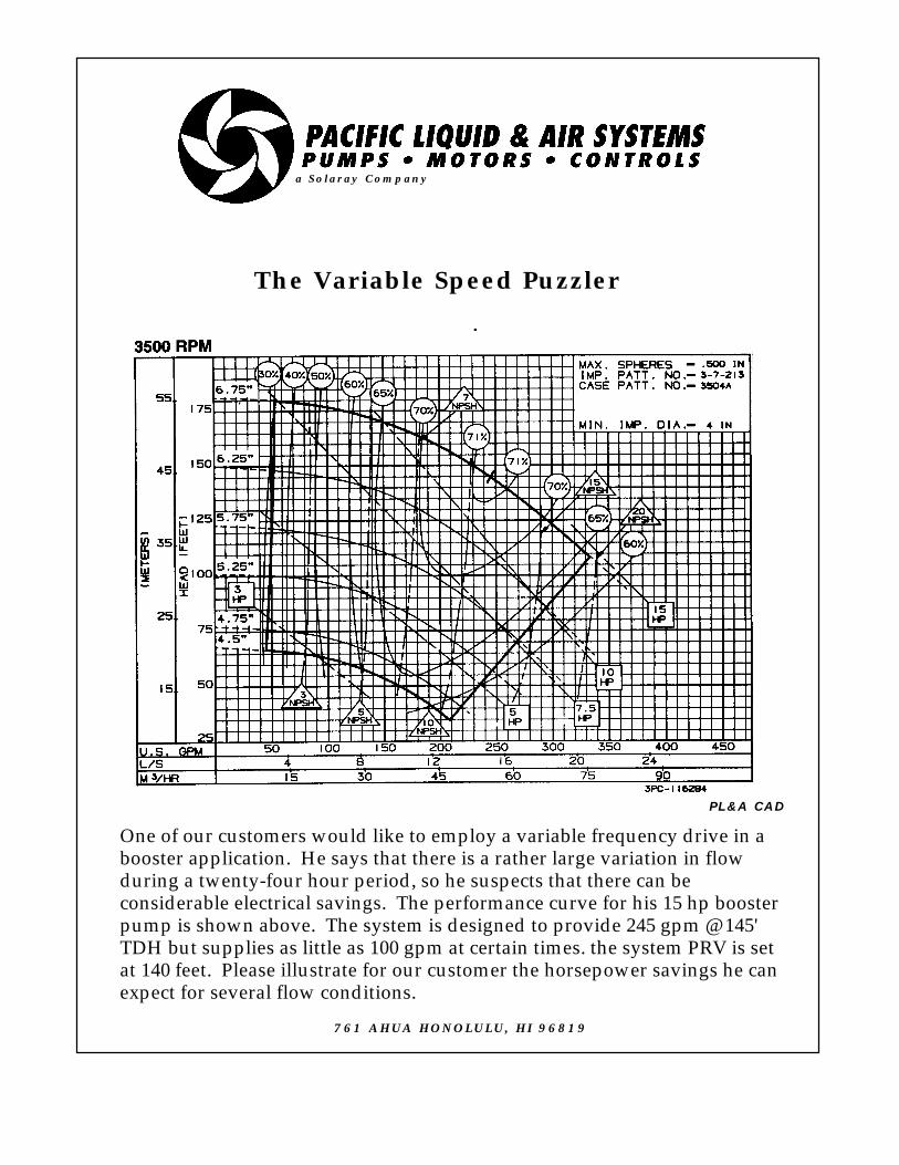
The Variable Speed Puzzler
One of our customers would like to employ a variable frequency drive in abooster application. He says that there is a rather large variation in flowduring a twenty-four hour period, so he suspects that there can beconsiderable electrical savings. The performance curve for his 15 hp boosterpump is shown above. The system is designed to provide 245 gpm @ 145'TDH but supplies as little as 100 gpm at certain times. the system PRV is setat 140 feet. Please illustrate for our customer the horsepower savings he canexpect for several flow conditions.
a Solaray Company
PL&A CAD
761 AHUA HONOLULU, HI 96819
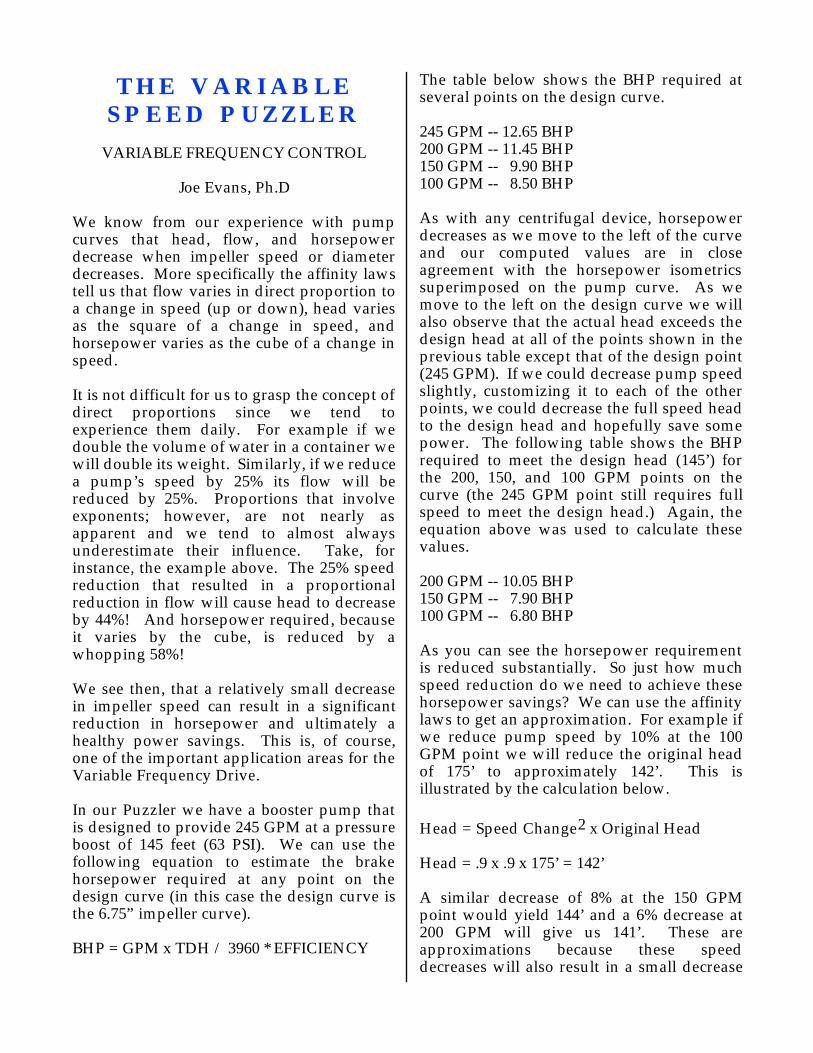
THE VARIABLE SPEED PUZZLER
VARIABLE FREQUENCY CONTROL
Joe Evans, Ph.D
We know from our experience with pump curves that head, flow, and horsepower decrease when impeller speed or diameter decreases. More specifically the affinity laws tell us that flow varies in direct proportion to a change in speed (up or down), head varies as the square of a change in speed, and horsepower varies as the cube of a change in speed.
It is not difficult for us to grasp the concept of direct proportions since we tend to experience them daily. For example if we double the volume of water in a container we will double its weight. Similarly, if we reduce a pump’s speed by 25% its flow will be reduced by 25%. Proportions that involve exponents; however, are not nearly as apparent and we tend to almost always underestimate their influence. Take, for instance, the example above. The 25% speed reduction that resulted in a proportional reduction in flow will cause head to decrease by 44%! And horsepower required, because it varies by the cube, is reduced by a whopping 58%!
We see then, that a relatively small decrease in impeller speed can result in a significant reduction in horsepower and ultimately a healthy power savings. This is, of course, one of the important application areas for the Variable Frequency Drive.
In our Puzzler we have a booster pump that is designed to provide 245 GPM at a pressure boost of 145 feet (63 PSI). We can use the following equation to estimate the brake horsepower required at any point on the design curve (in this case the design curve is the 6.75” impeller curve).
BHP = GPM x TDH / 3960 * EFFICIENCY
The table below shows the BHP required at several points on the design curve.
245 GPM -- 12.65 BHP200 GPM -- 11.45 BHP150 GPM -- 9.90 BHP100 GPM -- 8.50 BHP
As with any centrifugal device, horsepower decreases as we move to the left of the curve and our computed values are in close agreement with the horsepower isometrics superimposed on the pump curve. As we move to the left on the design curve we will also observe that the actual head exceeds the design head at all of the points shown in the previous table except that of the design point (245 GPM). If we could decrease pump speed slightly, customizing it to each of the other points, we could decrease the full speed head to the design head and hopefully save some power. The following table shows the BHP required to meet the design head (145’) for the 200, 150, and 100 GPM points on the curve (the 245 GPM point still requires full speed to meet the design head.) Again, the equation above was used to calculate these values.
200 GPM -- 10.05 BHP150 GPM -- 7.90 BHP100 GPM -- 6.80 BHP
As you can see the horsepower requirement is reduced substantially. So just how much speed reduction do we need to achieve these horsepower savings? We can use the affinity laws to get an approximation. For example if we reduce pump speed by 10% at the 100 GPM point we will reduce the original head of 175’ to approximately 142’. This is illustrated by the calculation below.
Head = Speed Change2 x Original Head
Head = .9 x .9 x 175’ = 142’
A similar decrease of 8% at the 150 GPM point would yield 144’ and a 6% decrease at 200 GPM will give us 141’. These are approximations because these speed decreases will also result in a small decrease

in flow. We could calculate these values precisely, but the necessary math complicates matters unjustifiably.
You may also use the affinity laws to calculate horsepower at each of these points. If you choose to do so, you will find that they agree closely with the values in the table above.
So how can a VFD control pump speed in such a way that it maintains design head across the entire pump curve? There are a number of ways but the simplest is to use a pressure transducer to monitor pressure in real time and feed that information to the VFD. The VFD, in turn, will slowly increase or decrease (ramp) the frequency of the power it delivers to the pump based upon the information it receives from the transducer. If flow changes are gradual (ie not 200 GPM one second and 100 GPM the next) a VFD can do a remarkable job of stabilizing pressure. If flow rates do vary substantially over shorter periods, the system can be adjusted to err on the high side although power savings will not be as pronounced.
Not all pressure boost applications are candidates for VFD control. Pumps that exhibit very flat curves are not good candidates (even though they may be suitable for VFD control in circulation applications). And, as mentioned above, those applications that exhibit radical excursions in flow may be better suited for staged, multi-pump systems.
761 Ahua Honolulu, HI 96819
Phone 808.536.7699 Fax 808.536.8761www.pacificliquid.com

a Solaray Company
The Crazy Impeller Puzzler
An electric motor can function as a generator.Can a pump function as another machine?When is an impeller not an impeller? That crazylooking thing in the upper right cannot be an impeller can it? Upon what principle does it
operate?
761 AHUA HONOLULU, HI 96819

THE CRAZY IMPELLER PUZZLER
RUNNERS
Joe Evans, Ph.D
When is an impeller not an impeller? Well, when it’s a runner. And, when is a pump a different machine? When it uses a runner instead of an impeller.
In many pumping applications, the liquid that is pumped remains at a high pressure or elevation even after the pumping cycle is complete. Instead of destroying this potential energy by dissipating it, a hydraulic turbine can recover it for productive work.
The hydraulic turbine is basically a pump (albeit a specially designed one) that utilizes flowing fluid to induce rotation. Its function is similar to the steam and gas turbine. In the hydraulic turbine, the impeller or propeller normally associated with a pump becomes a runner and, water flowing through or past it turns a shaft that can perform work.
Probably the most familiar application for hydraulic turbines today is hydroelectric power generation. These units convert the potential energy of water stored behind a dam into mechanical energy that drives generators. One of the oldest applications is that of fire fighting in mills that utilize a natural head of water in their normal operation. Still another application is that of fishways that enable migrating fish to travel upstream over a dam. Also, large scale reverse osmosis plants employ hydraulic turbines to recover energy from the high pressure side of their semipermeable membranes. In these applications, as much as 70% of the feedwater (at 300 to 500 PSI) is rejected.
The oldest and simplest hydraulic turbine is the waterwheel. It was first used by the Greeks and is still used today in many parts of the world. In the first century BC the
Roman engineer Marcus Pollio described the so called undershot waterwheel which was a vertical wheel with its underside placed in a stream. About a century later the more efficient overshot wheel (the one we recognize as a millwheel) became popular in hilly regions. The original design of the waterwheel did not change significantly until the eighteenth century when a French engineer devised an undershot wheel with curved blades that raised its efficiency by almost 70%.
The British born American engineer James Francis designed an impeller like turbine (upper left of the Puzzler) in which the flow was inward. In operation it is much like a centrifugal pump running backward. Liquid enters what would be the discharge of a tangential centrifugal pump, traverses the vanes, and exits what would be its suction. The Francis vane or reaction runner is used in applications involving heads of 100 to 1000 feet.
For lower heads, the propeller runner was developed. It operates much like an axial flow propeller pump and is designed for heads of 10 to 200 feet. Its more efficient cousin, the adjustable pitch runner, is shown at the upper left of the Puzzler.
That odd device at the upper right was devised during the gold rush days of California. Lester A. Pelton noticed that the flat paddle waterwheels employed in gold mining operations were very inefficient. They had to be huge in order to get a reasonable amount of work out of them. He designed a wheel with curved shaped paddles that cause water to make a u-turn upon impact and, in doing so, greatly increased the work it could do. So why does a u-turn increase the wheel’s capability? Lets investigate.
According to Newton’s first law1 , Pelton’s moving waterwheel possesses momentum
1 An object in motion (or at rest) will tend to remain in motion (or at rest) in a straight line and at a constant velocity unless it is acted upon by some outside force.

(inertia in motion) equal to its mass times its velocity (M=mv). The wheel can posses a large momentum if either its mass or velocity (or both) are large. For example, a ship moving at a low velocity can have a large momentum but so can a small projectile moving at a very high velocity.
A change in momentum occurs when either mass of velocity changes. If we have a change in momentum and mass remains the same, then velocity must change. What causes velocity to change? Acceleration. And what causes acceleration? A force and, in this case, it is the force of moving water. As water strikes the surface of the wheel’s paddles, it transfers energy to the wheel. The greater the mass and velocity of the water striking the paddles, the greater the change in velocity of the wheel and hence the greater the change in momentum. But, there is another important consideration here -- how long the force of the water is in contact with the paddle. The product of a force and the time it acts is called Impulse.
Impulse = Ft = F∆t = m∆v
If you want to increase the momentum of something as much as possible, you not only apply as much force as possible but also extend the application of the force for as long as possible.
The curved paddles of the Pelton wheel are designed to keep water in contact with their surfaces for a longer period than those of a flat blade wheel. But the Pelton design goes even further. It forces the water to make a u-turn and “bounce” away from the blade surface. In doing so, it greatly increases the impulse of the water on the blade. Remember that anytime something bounces, it imparts more energy to the bouncee than it would if it didn’t bounce.
The Pelton or impulse runner is used in high head applications. One of its great strengths is that its torque is highest at zero speed. Because of this, it is often used to start large pumps and other machinery which, once up
to speed, can be powered by an electric motor.
If you would like to see how big these three types of turbine runners can get, copy the following address and paste it in your browser.
http://mecheng1.uwaterloo.ca/~da3johns/handouts/turbo.html This address is the University of Warterloo’s Album of Turbomachinery web page.
761 Ahua Honolulu, HI 96819
Phone 808.536.7699 Fax 808.536.8761www.pacificliquid.com

The Hot & Cold Puzzler
P1 P2
r=50' r=50'
2" CU PIPE50 GPM WATER @ 180˚F
2" CU PIPE50 GPM WATER @ 70˚F
The two applications above show circulating pumps P1 & P2 circulating water in a clockwise direction through a vertical loopof copper pipe. If P1 is sized correctly, can it be substituted for P2in the right hand loop. What would be the effect if the pipe size isreduced to 1"? Is any work done by either of these systems? Howdo friction and flow vary across the diameter of the pipe?
a Solaray Company
PL&A CAD
761 AHUA HONOLULU, HI 96819

THE HOT & COLD PUZZLER
LIQUID FRICTION & VISCOSITY
Joe Evans, Ph.D
It probably didn’t take too long to recognize that friction is the underlying theme of this puzzler. There is quite a bit to be learned here and we can only scratch the surface (a little friction humor), so you may want to do some additional reading on your own.
Lets introduce friction by starting with the Puzzler’s question about work. Is there any work performed when one circulates water in a vertical or even a horizontal loop? Work is defined as the force applied to a body times the distance the body is moved in the direction of the force (w=fd). For example if you lift a 25 pound object to a height of one foot you will have performed 25 lbft of work. In this case you exerted a force of 25 pounds against the counteracting force, gravity, over a distance of one foot.
In either of the circulation loops the pumps move water from the bottom of the loop to the top, a vertical distance of 100 feet. Assume for a moment that 10 pounds of water is pumped from bottom to top. In doing so, it would appear that the pump performs 1000 lbft of work. But it doesn’t. For every pound of water pumped to the top, one pound falls down the other side due to gravity. When the system is static and no water is being circulated, the pump’s suction and discharge see the same pressure exerted by two separate 100 foot water columns that happen to be connected at the top. Put another way, the suction pressure available is equal to discharge pressure required to move water to the top of the loop. In fact regardless of where the pump is located in the loop, the pressure on its suction and discharge will always be the same. All it takes then, is just enough “umph” to overcome the static condition for circulation to begin.
According to Bernoulli’s equation water flowing steadily in a pipe remains at a constant pressure but, in practice, we know that this is not true. Pressure will decrease over distance unless some additional force is added. This decrease in pressure over distance is due to the force called friction. Unlike centrifugal and coriolis forces, friction is a true force and is due to the interaction of matter. In the case of our circulation loop it arises from the interaction of water with the pipe wall. Friction is one of the least understood forces in nature. In fact, most of our knowledge tends to be empirical and thus we find ourselves using friction tables instead of equations.
So the answer is yes, some work is performed by the pumps but not nearly as much as one might imagine. The only work performed is that required to overcome friction in the system. After all, Newton’s first law tells us that a body in motion tends to remain in motion unless it is acted upon by some outside force. In the case of circulation, gravity is canceled and the only outside force that remains is friction.
Water belongs to a category of fluids known as Newtonian fluids. These fluids are characterized by maintaining a constant viscosity regardless of their flow rate (velocity). Viscosity is a measure of a fluid’s tendency to resist a shearing force. Water has a very low viscosity and, when flowing through a pipe, is said to undergo viscous or laminar flow and is illustrated in the figure below..
Laminar Flow
Under laminar flow conditions, water flows through a pipe in concentric layers with its maximum velocity at the very center of the

pipe. Velocity at the pipe wall is essentially zero and there is very little mixing among the layers.
The following equation, known as Poiseuille’s Law, quantifies resistance to flow (R).
R = (8nL / πr4)Q
Where: n is viscosity, L is length of the conduit, r is its radius, and Q is flow
Since friction is proportional to R, his equation allows us to answer the other two questions posed by the Puzzler. Notice that the resistance to flow is inversely proportional to the fourth power of the radius of the pipe. If we reduce the conduit size by one half and flow remains the same, friction increases by a factor of sixteen!
We can also see that friction is directly proportional the the viscosity of the fluid (n). Water at 70 degrees F has a viscosity of 1.0 cp. At the elevated temperature of 180 degrees F its viscosity decreases to 0.35 cp. In a theoretical world, if we were to size the pump perfectly for the higher temperature application, the pump could not overcome the increased friction (2.85 times more) of the cooler water. In the real world there is no discernible difference.
Although the viscosity of a Newtonian fluid like water remains constant with increasing velocity, its flow characteristics do not. At some point laminar flow breaks down and turbulent flow occurs. As shown in the figure below, considerable mixing occurs and the velocity becomes nearly the same across the entire diameter of the pipe.
Turbulent Flow
As you can see below, this has a drastic effect upon our resistance to flow equation.
R = (8nL / πr5)Q2
The result is a dramatic increase in friction over that of laminar flow.
There is a range between laminar and turbulent flow referred to as mixed flow. This is a very unstable condition and flow tends to vary continuously between laminar and viscous.
The Reynolds Number (R) is a dimensionless number used to predict the type of flow a particular fluid will undergo. It is a ratio of flow rate to viscosity and takes the following form.
R = Q /(d * n/SG)
Where: Q is flowd is diameter of the conduitn is viscositySG is specific gravity
A Reynolds Number lower than 63 indicates laminar flow while those higher than 63 predict turbulent flow. Numbers in the vicinity of 63 can indicate mixed flow.
761 Ahua Honolulu, HI 96819
Phone 808.536.7699 Fax 808.536.8761
www.pacificliquid.com

The Worn Pump Puzzler
200'
a Solaray Company
PL&A CAD
CONTROLBOX
4", 1.5HP12 GPM
SUB
230V1 PH
One of our Maui customers is replacinghis well pump for the second time in fiveyears. Both of the failed pumps had wornimpellers and staging and, the mostrecent one had damaged splines on theupper portion of the motor shaft. Thepump is used to supply water to a tank atthe well head. His contractor says thatthe pump is too large. He has suggested a1 hp model that will produce 12 gpm atabout 230 feet. The customer wants thelarger model because he wants theflexibility of additional pressure shouldhis application change. The 1.5 hp pumpproduces 12 gpm at almost 400 feet. Whatis causing the pump to fail prematurelyand what can be done to prevent it?
761 AHUA HONOLULU, HI 96819
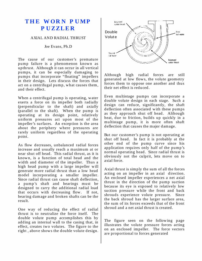
THE WORN PUMP PUZZLER
AXIAL AND RADIAL THRUST
Joe Evans, Ph.D
The cause of our customer’s premature pump failure is a phenomenon known as upthrust. Although it can occur in all vertical pumps, it can be especially damaging to pumps that incorporate “floating” impellers in their design. Lets discuss the forces that act on a centrifugal pump, what causes them, and their effect.
When a centrifugal pump is operating, water exerts a force on its impeller both radially (perpendicular to the shaft) and axially (parallel to the shaft). When the pump is operating at its design point, relatively uniform pressures act upon most of the impeller’s surfaces. An exception is the area about the periphery where pressures are rarely uniform regardless of the operating point.
As flow decreases, unbalanced radial forces increase and usually reach a maximum at or near shut off head. This radial thrust, as it is known, is a function of total head and the width and diameter of the impeller. Thus a high head pump with a large impeller will generate more radial thrust than a low head model incorporating a smaller impeller. Since radial thrust can cause shaft deflection, a pump’s shaft and bearings must be designed to carry the additional radial load that occurs with decreasing flow. If not, bearing damage and broken shafts can be the result.
One way of reducing the effect of radial thrust is to neutralize the force itself. The double volute pump accomplishes this by adding an internal wall to the casing that, in effect, creates two volutes. The figure to the right , above shows the double volute design.
DoubleVolute
Although high radial forces are still generated at low flows, the volute geometry forces them to oppose one another and thus their net effect is reduced.
Even multistage pumps can incorporate a double volute design in each stage. Such a design can reduce, significantly, the shaft deflection often associated with these pumps as they approach shut off head. Although heat, due to friction, builds up quickly in a multistage pump, it is more often shaft deflection that causes the major damage.
But our customer’s pump is not operating at shut off head. In fact it is probably at the other end of the pump curve since his application requires only half of the pump’s normal operating head. Since radial thrust is obviously not the culprit, lets move on to axial force.
Axial thrust is simply the sum of all the forces acting on an impeller in an axial direction. An enclosed impeller experiences a net axial thrust in the direction of the pump suction because its eye is exposed to relatively low suction pressure while the front and back shrouds experience volute pressure. Since the back shroud has the larger surface area, the sum of its forces exceeds that of the front shroud and a net axial thrust is created.
The figure seen on the following page illustrates the volute pressure forces acting on an enclosed impeller. The force vectors are proportional to forces generated

In the case of the overhung impeller (typical end suction pump) increased suction pressure decreases axial thrust while suction lift increases it. In small pumps this axial thrust can easily be accommodated by the pump or motor bearings assuming they are sized correctly. With very large pumps or those under extremely high suction pressure, this increased axial thrust can be significant and must be considered during design.
Just as the double volute can neutralize radial loads, a back wear ring design can neutralize axial imbalance. The figure below shows such a design.
By incorporating a wear ring and balancing holes in the back shroud, the surface area is reduced by an amount equal to the impeller eye. Since that portion is now under suction pressure, the volute axial forces are nearly equal and axial thrust is greatly reduced.
The semiopen impeller generates more axial thrust than does a closed impeller. Often these impellers will be fitted with “pump out” vanes on the back side of the rear (actually only) shroud. These vanes,
although not as effective as a back wear ring, act to reduce the unbalanced pressure. They also serve a secondary function in that they keep debris from accumulating in the seal area.
So far, our discussion has revolved about (a little radial humor) horizontally mounted pumps. Axial force takes on a new direction when a pump is installed in the vertical position.
The most obvious difference is that the weight of the pump’s rotating parts (shaft & impeller) and often those of the motor add to the axial thrust generated by the pump itself. This is especially significant in the case of a line shaft turbine where the shaft and impeller assembly can add thousands of pounds to the axial loading. It is apparent that thrust bearing design is critical for these pumps.
This is all quite interesting but, so far, nothing we have covered explains our customer’s problem. Well, it just so happens that an interesting phenomenon occurs when water flows through a pump that is mounted vertically with its impeller eye facing down. When water, moving vertically, exits the impeller eye it changes direction and flows horizontally through the vanes. In doing so it gains momentum and generates a force that acts upward. (Now we seem to be getting somewhere!) But alias, if we calculate this force we will find that it is negligible when compared to the downward force due to the pressure differential on the back of the impeller.
But wait a minute, isn’t the unbalanced axial thrust greater when the discharge head is high? What happens during startup when flow is at some maximum and head is at some minimum?
During startup, a vertical pump may reach operating speed in less than a second but it it may take several seconds for it to reach operating head. During this period it can operate at maximum capacity. Since the upward force generated by the change in
momentum varies as the square of flow, a momentary net upward force can occur during this period of low differential pressure. If the pump continues to run well beyond normal capacity, a permanent upward force can exist.
This momentary “upthrust”, as it is known, can be accommodated by vertical pumps such as the lineshaft turbine because the pump shaft is rigidly connected to the motor. Therefore the motor bearings can be sized to handle both the normal “downthrust” due to pressure differential and the momentary upthrust due to the momentum change. Continuous upthrust should be avoided because compression of the line shaft can cause it to buckle which can produce vibration and wear. A good “rule of thumb” is that capacity should never exceed 125% of BEP (best efficiency point). When submersible pumps are involved the problem of upthrust changes substantially.
Submersible motors, such as those manufactured by Franklin Electric, are specifically designed to accommodate the downthrust generated by multistage submersible pumps. Depending upon the motor model the thrust bearing, located beneath the rotor shaft, can handle as much as ten thousand pounds of downthrust. They are also designed to deal with the problem of upthrust. The manner in which they do this is quite elegant. They simply ignore it. The splined shaft of the submersible motor allows the pump shaft a certain amount of axial movement. This puts the problem of upthrust squarely in the court of the pump manufacturer.
Most submersible pumps, with impellers fixed to the shaft, incorporate a upthrust bearing of some type. This device limits the the upward travel of the pump shaft and impellers and thus keeps the impellers from coming into contact with the pump bowls during startup. The device is intended to protect against momentary upthrust conditions and is not designed to accommodate continuous upward force. If a submersible is operated at over capacity for
long periods, the bearing will wear and allow contact between the impellers and bowls.
Many smaller submersibles utilize a floating impeller design. In this type of pump the impellers are not colleted to the shaft but are allowed to move axially within their bowl or diffuser assemblies. Their contact areas are protected against downthrust, but during upthrust there is less protection. Fortunately their composition, usually polycarbonate or some other forgiving material, allows for momentary upthrust. They cannot, however, survive continuous upthrust so it is particularly important that this type of pump be operated within the specific range indicated by the manufacturer.
For our customer, two remedies exist. Either he can install the pump suggested by the contractor or he can restrict the flow of the larger model. Although inefficient, the larger pump will operate correctly if it is loaded to its proper operating head.
761 Ahua Honolulu, HI 96819Phone 808.536.7699 Fax 808.536.8761
www.pacificliquid.com

a Solaray Company
PL&A CAD
4.5" 4.5"
The Differing Pressure Puzzler
A customer has two 3/4 hp, 3450 rpm, self priming pumps. Both have a1.25" suction and a 1" discharge. The two also have identical impellerdiameters of 4.5". He reports that the pump with the impeller shown onthe right produces about 30 psi at shut off. The one on the left; however,produces almost 65 psi at shut off. If head depends upon an impeller'speripheral velocity and if the peripheral velocities of both impellers arethe same, why do they generate different pressures? Both pumps arepumping water so there is no difference in density.
761 AHUA HONOLULU, HI 96819
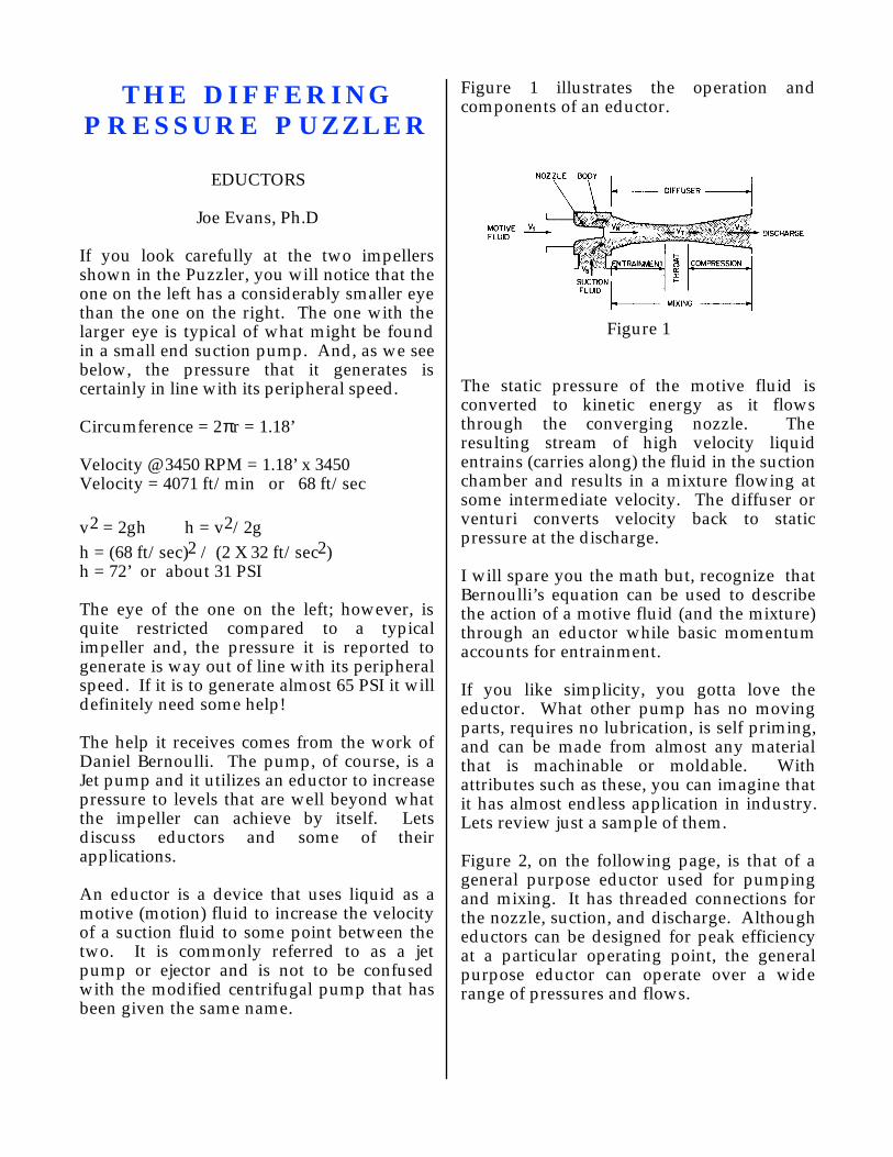
THE DIFFERING PRESSURE PUZZLER
EDUCTORS
Joe Evans, Ph.D
If you look carefully at the two impellers shown in the Puzzler, you will notice that the one on the left has a considerably smaller eye than the one on the right. The one with the larger eye is typical of what might be found in a small end suction pump. And, as we see below, the pressure that it generates is certainly in line with its peripheral speed.
Circumference = 2πr = 1.18’
Velocity @ 3450 RPM = 1.18’ x 3450Velocity = 4071 ft/min or 68 ft/sec
v2 = 2gh h = v2/2g
h = (68 ft/sec)2 / (2 X 32 ft/sec2)h = 72’ or about 31 PSI
The eye of the one on the left; however, is quite restricted compared to a typical impeller and, the pressure it is reported to generate is way out of line with its peripheral speed. If it is to generate almost 65 PSI it will definitely need some help!
The help it receives comes from the work of Daniel Bernoulli. The pump, of course, is a Jet pump and it utilizes an eductor to increase pressure to levels that are well beyond what the impeller can achieve by itself. Lets discuss eductors and some of their applications.
An eductor is a device that uses liquid as a motive (motion) fluid to increase the velocity of a suction fluid to some point between the two. It is commonly referred to as a jet pump or ejector and is not to be confused with the modified centrifugal pump that has been given the same name.
Figure 1 illustrates the operation and components of an eductor.
Figure 1
The static pressure of the motive fluid is converted to kinetic energy as it flows through the converging nozzle. The resulting stream of high velocity liquid entrains (carries along) the fluid in the suction chamber and results in a mixture flowing at some intermediate velocity. The diffuser or venturi converts velocity back to static pressure at the discharge.
I will spare you the math but, recognize that Bernoulli’s equation can be used to describe the action of a motive fluid (and the mixture) through an eductor while basic momentum accounts for entrainment.
If you like simplicity, you gotta love the eductor. What other pump has no moving parts, requires no lubrication, is self priming, and can be made from almost any material that is machinable or moldable. With attributes such as these, you can imagine that it has almost endless application in industry. Lets review just a sample of them.
Figure 2, on the following page, is that of a general purpose eductor used for pumping and mixing. It has threaded connections for the nozzle, suction, and discharge. Although eductors can be designed for peak efficiency at a particular operating point, the general purpose eductor can operate over a wide range of pressures and flows.

Figure 2
Two widespread uses of eductors are those of mixing and blending. Their many attributes make them excellent alternatives to mechanical agitators. In addition to an eductor’s inherent mixing capability, its high velocity output also provides agitation. One of the simplest eductors used in mixing is one known as the Sparger nozzle. Its single connection makes installation no more difficult than that of a sprinkler head. Mixing eductors are also available with a proportioning valve at the nozzle entry. This gives them the capability to blend fluids and produce emulsions.
Eductors are also used in the pumping of solids and slurries. Sand and mud eductors are fitted with agitating nozzles that keep the solid material in suspension so that it will be entrained with the the suction fluid. So called “hopper” eductors entrain granular solids and convey them from point to point in a process line.
Earlier we defined an eductor as a jet pump that uses a liquid as its motive fluid. Its close relative, the siphon, is also a jet pump but, unlike the eductor, it uses a condensable vapor as its motive force. Steam is the most common motive fluid used by siphons. Although we will not go into them here, the siphon looks very much like a eductor except
that it uses a converging / diverging nozzle that allows the motive fluid to reach supersonic velocities. Its application is similar to that of the eductor except that the suction fluid must be capable of condensing the motive fluid.
Figure 3 below shows a cross section of what the water systems industry refers to as a jet pump. Actually it is a two stage pump consisting of a jet pump (eductor or ejector) first stage and a centrifugal second stage. The centrifugal stage serves two functions in that it provides both motive force and discharge pressure.
VENTURI
NOZZLE
IMPELLER
Figure 3
Lets take a look at this multistage pump’s operation. When the pump is started water exits the impeller and flows into the diffuser where velocity is converted to static pressure. Some of the water exiting the diffuser flows out the pump’s discharge, but a significasnt portion is diverted to the eductor’s nozzle. The diverted portion becomes the motive fluid and entrains water from the suction area of the pump as it exits the nozzle. The velocity of the mixture is at some intermediate velocity that lies between those of the motive and suction water. The mixture then enters the eductor’s diffuser or venturi where its velocity is converted back to static pressure. The pressure of the mixture as it exits the first stage of the pump is now at some intermediate pressure that lies between those of the two water sources.

After gaining pressure in the first stage, the water enters the eye of the centrifugal pump’s impeller. In the impeller pressure is once again converted to velocity and accelerated to a greater velocity as it exits the impeller’s vanes. The diffuser yet again converts velocity to pressure and the water exits the second stage. After exiting the second stage, the cycle begins again.
The ultimate pressure generated by this type of arrangement depends upon the static pressure supplied by the centrifugal pump at a given flow rate and the design of the ejector. It is essentially the sum of the pressures developed by the two stages.
Figure 4 compares the actual performance curves of three 3/4 HP pumps. The solid line curve is that of our jet pump while the closely spaced dashed line is that of a typical end suction centrifugal. The other dashed line plots the curve of a two stage centrifugal.
10 20 30 40
160'
80'
40'
120'
Figure 4
One of the first comparisons to catch our eye is that the jet and two stage pumps exhibit rather steep curves while the end suction pump displays one with a gentle slope. A second is that, to a point, the performance of the jet pump and two stage pump closely parallel one another.
The gentle sloping curve of the end suction pump is typical of an impeller with a relatively high eye/vane size to diameter ratio. The one shown provides moderate pressure over a broad range of flow. Conservation of energy requires that the two stage pump’s flow rate be lower than that of the end suction. It cannot achieve increased head and still offer a broad range of flow unless additional power is applied.
The jet pump shown is designed to operate over a limited range of flow. Throughout this range; however, it equals or betters the performance of the two stage pump and does so at a much lower production cost. At the point where its curve drops sharply, insufficient flow is diverted to the eductor and the pressure of the motive fluid decreases. Thus the majority of the water entering the ejector’s diffuser does so via the reduced pressure created by the impeller rather than entrainment. The result is a drastic drop in discharge pressure.
761 Ahua Honolulu, HI 96819
Phone 808.536.7699 Fax 808.536.8761
www.pacificliquid.com
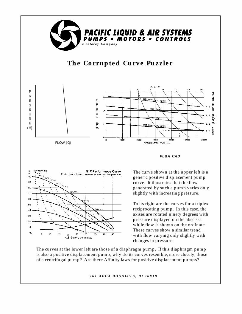
a Solaray Company
PL&A CAD
761 AHUA HONOLULU, HI 96819
FLOW (Q)
PRESSURE
(H)
The Corrupted Curve Puzzler
The curve shown at the upper left is ageneric positive displacement pumpcurve. It illustrates that the flowgenerated by such a pump varies onlyslightly with increasing pressure.
To its right are the curves for a triplexreciprocating pump. In this case, theaxises are rotated ninety degrees withpressure displayed on the abscissawhile flow is shown on the ordinate. These curves show a similar trend with flow varying only slightly withchanges in pressure.
The curves at the lower left are those of a diaphragm pump. If this diaphragm pumpis also a positive displacement pump, why do its curves resemble, more closely, thoseof a centrifugal pump? Are there Affinity laws for positive displacement pumps?

THE CORRUPTED CURVE PUZZLER
POSITIVE DISPLACEMENT PUMPS
Joe Evans, Ph.D
PART I RECIPROCATING PUMPS
There are many pump designs that fall into the positive displacement category but, for the most part, they can be nicely divided into two basic groups. The reciprocating group operates via pistons, plungers, or diaphragms while rotary pumps use gears, lobes, screws, vanes, and peristaltic action. Their common design thread is that energy is added to the pumped fluid only periodically where, in dynamic pumps, it is added continuously.
Since most of our work tends to involve the first group we will focus our immediate attention in their direction.
PISTON & PLUNGER PUMPS
The piston pump is one of the most common reciprocating pumps and, prior to the development of high speed drivers which enhanced the popularity of centrifugals, it was the pump of choice for a broad range of applications. Today , they are most often seen in lower flow, moderate (to 2000 PSI) pressure applications. Its close cousin, the plunger pump, is designed for higher pressures up to 30,000 PSI. The major difference between the two is the method of sealing the cylinders. In a piston pump the sealing system (rings, packing etc) is attached to the piston and moves with it during its stroke. The sealing system for the plunger pump is stationary and the plunger moves through it during its stroke.
Reciprocating pumps operate on the principle that a solid will displace a volume of liquid equal to its own volume. Figure 1 is a schematic of a generic double acting piston pump.
Figure 1
If we were to remove the two valves at the left hand side of the figure and replace them with an extension of the cylinder, we would have a single acting pump. The single acting pump discharges water only on its forward stroke while the double acting pump discharges on its return stroke as well. During the suction stroke (right to left) the single acting pump’s discharge valve closes and allows fluid to enter the cylinder via the suction valve. When the piston changes direction (reciprocates) the suction valve closes and water is discharged through the discharge valve. In the double acting pump, the same sequence occurs during both strokes and almost twice as much fluid is discharged per unit time.
PRESSURE
The head created by a centrifugal pump depends upon the velocity it imparts to the fluid via its impeller. Therefore, for any given impeller diameter and rotational speed, head will be some maximum, unvarying amount. Not so for reciprocating pumps. Although they will have a maximum operating pressure rating, the maximum pressure (P) attained depends upon the application. Against a closed discharge valve, pressure is limited only by the capability of the driver and the strength of the materials employed. Only the “breaking point” of some component will limit discharge pressure. Therefore some form of pressure relief must be supplied if an application is capable of exceeding the pressure rating of the pump.

CAPACITY
The capacity (Q) of a single acting piston or plunger pump is proportional to its displacement (D) per unit time. The displacement is the calculated capacity of the pump, assuming 100% hydraulic efficiency, and is proportional to the cross sectional area of the piston (A), the length of its stroke (s), the number of cylinders (n), and the pump’s speed in rpm. In gallons per minute it is:
D = (A x s x n x rpm) / 231
In the case of double acting pumps the cross sectional area of the piston or plunger is doubled and the cross sectional area of the piston rod (a) is subtracted. Again, in gallons per minute D is:
D = ((2A - a) x s x n x rpm) / 231
In real life the theoretical capacity of a piston or plunger pump is tempered by several factors. One is known as slip (S). The major component of slip is the leakage of fluid back through the discharge or suction valve as it is closing (or seated). It can reduce calculated displacement from 2 to 10% depending upon valve design and condition. Increased viscosity will also adversely affect slip.
Another important factor that affects a reciprocating pump’s capacity is something called volumetric efficiency (VE). VE is expressed as a percentage and is proportional to the ratio of the total discharge volume to the piston or plunger displacement. Figure 2 illustrates how we arrive at this ratio.
Figure 2
The ratio (r) is shown to be (c+d)/d where d is the volume displaced by the piston or plunger and c is the additional volume between the discharge and suction valves. The smaller this ratio the better the volumetric efficiency. Expressed mathematically it looks like this:
VE = 1 - (P x b x r) - S
where P is pressure, b is the liquid’s compressibility factor, r is the volume ratio, and S is slip. The compressibility factor for
water is quite small (3 X 10⁻⁶ inches per pound of pressure at ambient temperature) but at pressures greater than 10,000 PSI it does become a factor.
Figure 2 also clearly illustrates the volumetric displacement operating principle of these pumps. Although there is no cylinder wall around the plunger at the bottom of its stroke, it still displaces fluid equal to its own volume.
Now, we can finally state the actual capacity of a reciprocating pump. It is quite simply:
Q = D x VE
POWER
The power required to drive a reciprocating pump is quite straight forward. It is simply proportional to pressure and capacity. In brake horsepower it is:
bhp = (Q X P) / (1714 X ME)
where 1714 is the bhp conversion factor and ME is mechanical efficiency. Mechanical efficiency is the percentage of the driver power that is not lost in the pump’s power frame and other reciprocating parts. The mechanical efficiency of a piston or plunger pump ranges between 80 and 95% depending upon speed, size, and construction.
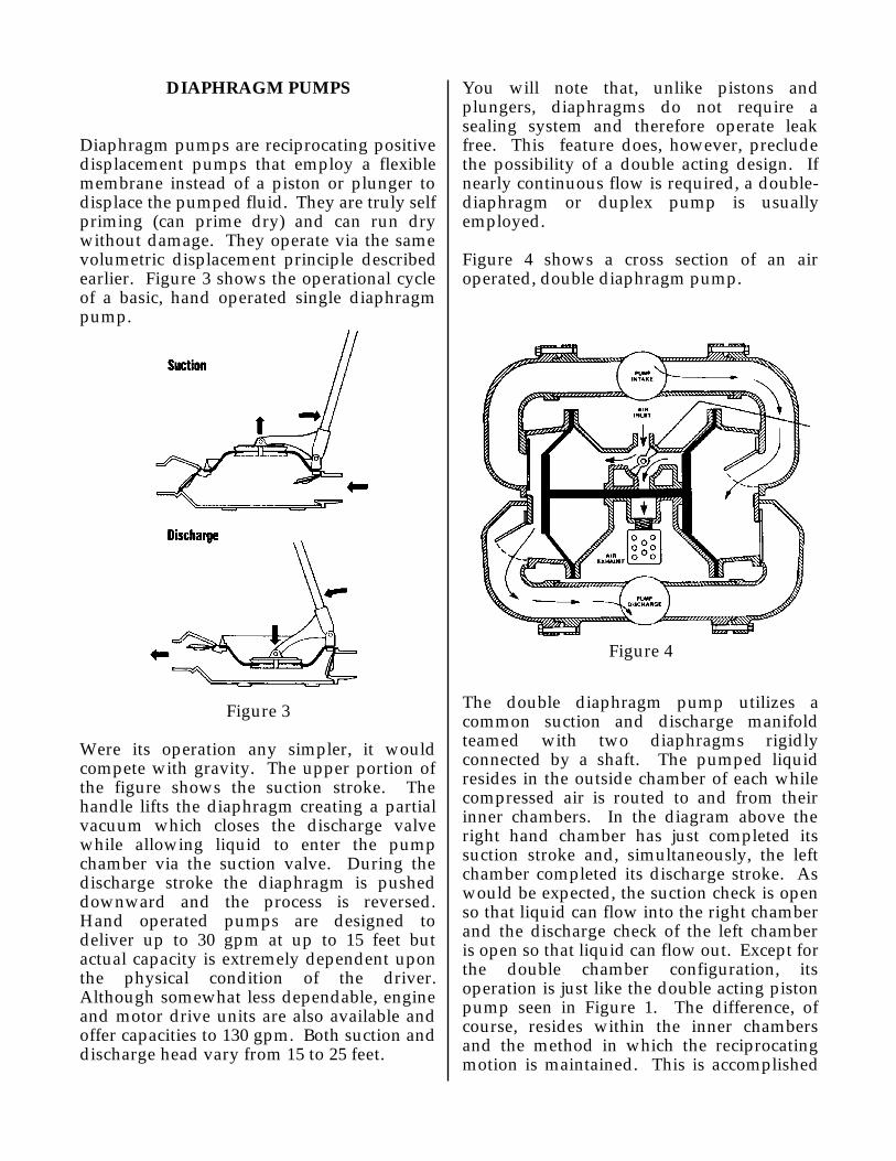
DIAPHRAGM PUMPS
Diaphragm pumps are reciprocating positive displacement pumps that employ a flexible membrane instead of a piston or plunger to displace the pumped fluid. They are truly self priming (can prime dry) and can run dry without damage. They operate via the same volumetric displacement principle described earlier. Figure 3 shows the operational cycle of a basic, hand operated single diaphragm pump.
Figure 3
Were its operation any simpler, it would compete with gravity. The upper portion of the figure shows the suction stroke. The handle lifts the diaphragm creating a partial vacuum which closes the discharge valve while allowing liquid to enter the pump chamber via the suction valve. During the discharge stroke the diaphragm is pushed downward and the process is reversed. Hand operated pumps are designed to deliver up to 30 gpm at up to 15 feet but actual capacity is extremely dependent upon the physical condition of the driver. Although somewhat less dependable, engine and motor drive units are also available and offer capacities to 130 gpm. Both suction and discharge head vary from 15 to 25 feet.
You will note that, unlike pistons and plungers, diaphragms do not require a sealing system and therefore operate leak free. This feature does, however, preclude the possibility of a double acting design. If nearly continuous flow is required, a double-diaphragm or duplex pump is usually employed.
Figure 4 shows a cross section of an air operated, double diaphragm pump.
Figure 4
The double diaphragm pump utilizes a common suction and discharge manifold teamed with two diaphragms rigidly connected by a shaft. The pumped liquid resides in the outside chamber of each while compressed air is routed to and from their inner chambers. In the diagram above the right hand chamber has just completed its suction stroke and, simultaneously, the left chamber completed its discharge stroke. As would be expected, the suction check is open so that liquid can flow into the right chamber and the discharge check of the left chamber is open so that liquid can flow out. Except for the double chamber configuration, its operation is just like the double acting piston pump seen in Figure 1. The difference, of course, resides within the inner chambers and the method in which the reciprocating motion is maintained. This is accomplished

by an air distribution valve that introduces compressed air to one diaphragm chamber while exhausting it from the other. Upon completion of the stroke the valve rotates 90 degrees and reciprocation occurs.
I introduced this section with the statement that diaphragm pumps are positive displacement in nature. Generally this is an accurate statement but not so in the case of air operated units. They are, of course, displacement pumps but their discharge pressure is limited to the air pressure supplied to power them.
So why do the diaphragm pump curves in our Puzzler look more like those of centrifugal pumps? Well, there are two reasons. First, the geometry of the diaphragm and pumping chamber lends itself to a relatively large volumetric ratio (r). When this is combined with a fairly significant check valve slip (S), the volumetric efficiency (VE) can be quite a bit lower than that of a piston or plunger pump. This in itself will contribute to a reduction in the slope of the pump curve. But the larger factor, and the reason for the “centrifugal” shape is the compressibility of the driving air.
AFFINITY
Although we tend to associate affinity laws with centrifugal pumps, other mechanical devices also exhibit these “natural” relationships. In the case of positive displacement pumps the affinity laws are very straight forward.
FLOW - Flow varies directly with a change in speed. If the rotational speed is doubled, flow is also doubled.
PRESSURE - Pressure is independent of a change in speed. If we ignore efficiency losses, the pressure generated at any given rotational speed will be that required to support flow.
HORSEPOWER - Horsepower varies directly with a change in speed. If we double the
rotational speed, twice as much power will be required.
NPSHR - Net Positive Suction Head required varies as the square of a change in speed. If we double the rotational speed NPSHR increases by four.
761 Ahua Honolulu, HI 96819Phone 808.536.7699 Fax 808.536.8761
www.pacificliquid.com
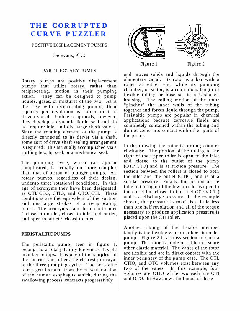
THE CORRUPTED CURVE PUZZLER
POSITIVE DISPLACEMENT PUMPS
Joe Evans, Ph.D
PART II ROTARY PUMPS
Rotary pumps are positive displacement pumps that utilize rotary, rather than reciprocating, motion in their pumping action. They can be designed to pump liquids, gases, or mixtures of the two. As is the case with reciprocating pumps, their capacity per revolution is independent of driven speed. Unlike reciprocals, however, they develop a dynamic liquid seal and do not require inlet and discharge check valves. Since the rotating element of the pump is directly connected to its driver via a shaft, some sort of drive shaft sealing arrangement is required. This is usually accomplished via a stuffing box, lip seal, or a mechanical seal.
The pumping cycle, which can appear complicated, is actually no more complex than that of piston or plunger pumps. All rotary pumps, regardless of their design, undergo three rotational conditions. In this age of acronyms they have been designated as OTI/CTO, CTIO, and OTO/CTI. These conditions are the equivalent of the suction and discharge strokes of a reciprocating pump. The acronyms stand for open to inlet / closed to outlet, closed to inlet and outlet, and open to outlet / closed to inlet.
PERISTALTIC PUMPS
The peristaltic pump, seen in figure 1, belongs to a rotary family known as flexible member pumps. It is one of the simplest of the rotaries, and offers the clearest portrayal of the three pumping cycles. The peristaltic pump gets its name from the muscular action of the human esophagus which, during the swallowing process, contracts progressively
Figure 1 Figure 2
and moves solids and liquids through the alimentary canal. Its rotor is a bar with a roller at either end while its pumping chamber, or stator, is a continuous length of flexible tubing or hose set in a U-shaped housing. The rolling motion of the rotor “pinches” the inner walls of the tubing together and forces liquid through the pump. Peristaltic pumps are popular in chemical applications because corrosive fluids are completely contained within the tubing and do not come into contact with other parts of the pump.
In the drawing the rotor is turning counter clockwise. The portion of the tubing to the right of the upper roller is open to the inlet and closed to the outlet of the pump (OTI/CTO) and is at suction pressure. The section between the rollers is closed to both the inlet and the outlet (CTIO) and is at a similar pressure. Finally, the portion of the tube to the right of the lower roller is open to the outlet but closed to the inlet (OTO/CTI) and is at discharge pressure. In the example shown, the pressure “stroke” is a little less than one half revolution and all of the torque necessary to produce application pressure is placed upon the CTI roller.
Another sibling of the flexible member family is the flexible vane or rubber impeller pump. Figure 2 is a cross section of such a pump. The rotor is made of rubber or some other elastic material. The vanes of the rotor are flexible and are in direct contact with the inner periphery of the pump case. The OTI, CTIO, and OTO volumes exist between any two of the vanes. In this example, four volumes are CTIO while two each are OTI and OTO. In Hawaii we find most of these
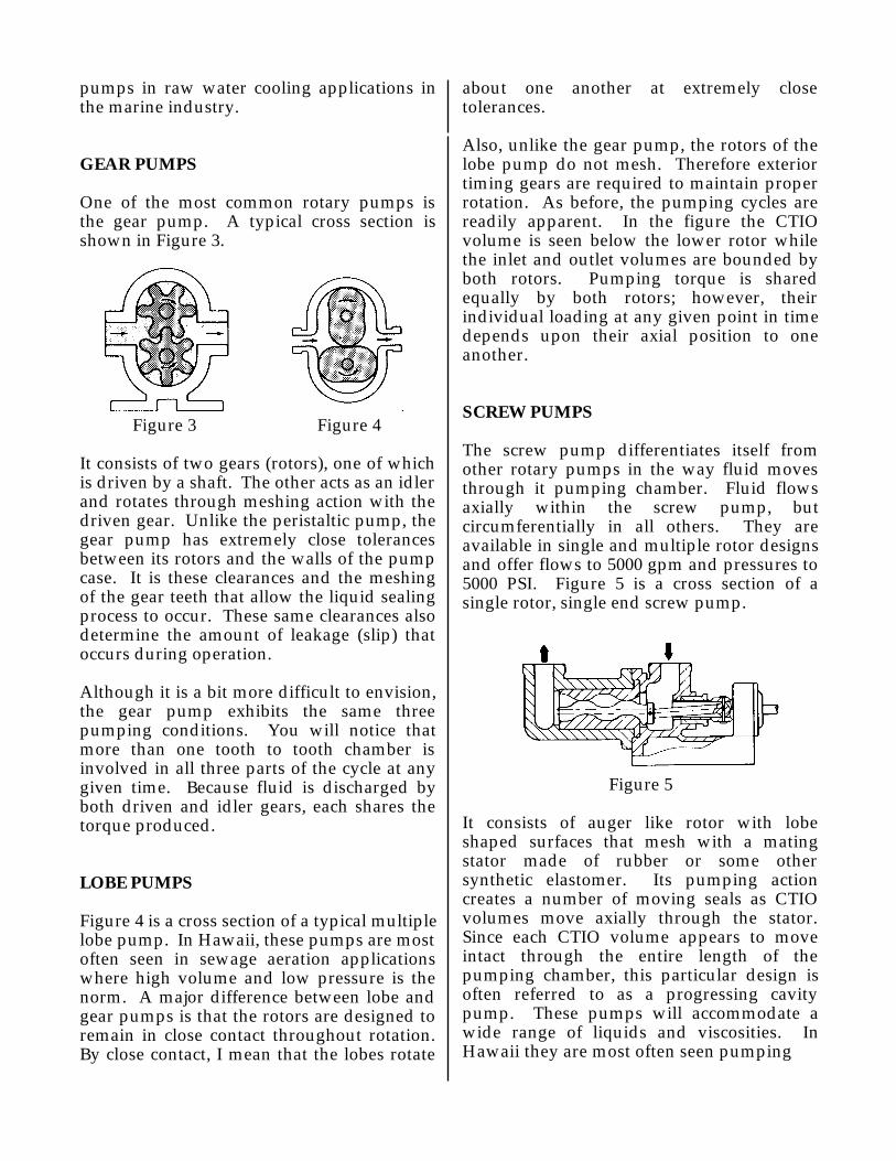
pumps in raw water cooling applications in the marine industry.
GEAR PUMPS
One of the most common rotary pumps is the gear pump. A typical cross section is shown in Figure 3.
Figure 3 Figure 4
It consists of two gears (rotors), one of which is driven by a shaft. The other acts as an idler and rotates through meshing action with the driven gear. Unlike the peristaltic pump, the gear pump has extremely close tolerances between its rotors and the walls of the pump case. It is these clearances and the meshing of the gear teeth that allow the liquid sealing process to occur. These same clearances also determine the amount of leakage (slip) that occurs during operation.
Although it is a bit more difficult to envision, the gear pump exhibits the same three pumping conditions. You will notice that more than one tooth to tooth chamber is involved in all three parts of the cycle at any given time. Because fluid is discharged by both driven and idler gears, each shares the torque produced.
LOBE PUMPS
Figure 4 is a cross section of a typical multiple lobe pump. In Hawaii, these pumps are most often seen in sewage aeration applications where high volume and low pressure is the norm. A major difference between lobe and gear pumps is that the rotors are designed to remain in close contact throughout rotation. By close contact, I mean that the lobes rotate
about one another at extremely close tolerances.
Also, unlike the gear pump, the rotors of the lobe pump do not mesh. Therefore exterior timing gears are required to maintain proper rotation. As before, the pumping cycles are readily apparent. In the figure the CTIO volume is seen below the lower rotor while the inlet and outlet volumes are bounded by both rotors. Pumping torque is shared equally by both rotors; however, their individual loading at any given point in time depends upon their axial position to one another.
SCREW PUMPS
The screw pump differentiates itself from other rotary pumps in the way fluid moves through it pumping chamber. Fluid flows axially within the screw pump, but circumferentially in all others. They are available in single and multiple rotor designs and offer flows to 5000 gpm and pressures to 5000 PSI. Figure 5 is a cross section of a single rotor, single end screw pump.
Figure 5
It consists of auger like rotor with lobe shaped surfaces that mesh with a mating stator made of rubber or some other synthetic elastomer. Its pumping action creates a number of moving seals as CTIO volumes move axially through the stator. Since each CTIO volume appears to move intact through the entire length of the pumping chamber, this particular design is often referred to as a progressing cavity pump. These pumps will accommodate a wide range of liquids and viscosities. In Hawaii they are most often seen pumping

sewage sludge and other solutions with suspended solids.
OPERATING CHARACTERISTICS
Pressure
As with reciprocating pumps the maximum pressure (P) generated by a rotary pump is determined by the application and the pump and driver components. Maximum working pressure is specified by the manufacturer while maximum differential pressure depends upon the pump’s fluid sealing capability.
Capacity
The capacity (Q) of a rotary pump is proportional to its displacement (D) times it driven speed (rpm) less slip (S).
Q = (D x rpm) - S
The displacement of a rotary pump is defined as the net volume of fluid transferred from OTI to OTO during one revolution. And, believe me when I say that this is all you will ever want to know! Because of the complex geometry that exists between the rotor and pump case, calculus is required to compute actual displacement. In fact it is often so complex that displacement is often approximated.
Slip is similar to that in a reciprocating pump and is defined as the quantity of fluid that leaks from OTO to OTI per unit time. It depends upon the clearances between the rotors and case and the operating pressure. Generally, slip increases in direct proportion to pressure and is most marked in designs like the flexible member pump. Flexible vane pumps (Figure 2) are especially subject to slip at higher pressures and, in fact, tend to be inherently protected against over pressure
Power
The power required for rotary pumps is calculated in the same manner as it is for
reciprocals.
bhp = (Q x P) / (1714 x ME)
where 1714 is the bhp conversion factor and ME is mechanical efficiency. Again, mechanical efficiency is the ratio of pump power output to pump power input.
Obviously, we do not have room here to cover all of the rotary pump designs. The five we discussed, however, are common ones and illustrate both differences in design and the pumping cycle shared by all. Neither have we the time to discuss some of the more important operational considerations. Such things as pulsation, accumulation, and pressure relief will have to wait for another Puzzler.
761 Ahua Honolulu, HI 96819Phone 808.536.7699 Fax 808.536.8761
www.pacificliquid.com

The Mumbo-Jumbo Puzzler
CLASS FINVERTER DUTYSEVERE DUTY
HOSTILE DUTY
PREMIUM EFFICIENCY
EPAC EFFICIENCYVECTOR DUTY
SPIKE RESISTANTPWM DUTYCLASS H
NEMA MG-1, SECTION IV, PART 31
MAGNET WIRE
THERMALEZE QS
One of our industrial customers is planning on replacing several of hisDC and constant speed AC motors with VFD compatible AC units. Heknows, from articles he has read, that the high switching speeds ofIGBT technology can potentially damage a motor’s windings. Hewants to purchase the right motor for each of his applications but isconfused by the unusually large selection of motor types and insulationgrades. Can you help him sort through NEMA MG - 1 Part 31 and givehim some guide lines for selecting the proper motor for a particularVFD application?
a Solaray Company
PL&A CAD
761 AHUA HONOLULU, HI 96819

THE MUMBO-JUMBO PUZZLER
MOTOR INSULATION
Joe Evans, Ph.D
This Puzzler displays a myriad of trade marks, motor types, and insulation classes which seem to be designed to confuse any potential VFD applications designer. And of course, there is that NEMA specification. Just what is an inverter or vector duty motor? Does insulation class play a role? How about the motor type -- EPAC, Premium, Hostile, etc?
As you will learn in a few minutes, the current generation of Variable Frequency Drives can place quite a bit of stress on a motor. The additional heat and voltage can potentially damage winding insulation. Motors that are designed specifically for VFD operation are usually referred to as “Inverter Duty” or by some trademark that sets them apart from a generic industrial motor. “Vector Duty” is usually reserved for VFD duty motors that are employed in high torque applications. In some applications these motors must develop full torque at zero RPM! Insulation class also plays an important role. Class F is the default insulation grade used in high quality industrial motors today; however, some manufacturers (USEM included) use a higher grade referred to as class H. Often the motor nameplate will still reflect class F because the motor leads do not meet the class H requirement. And finally motor type does make a difference because some types are built to a higher manufacturing standard than others.
NEMA MG-1 PART 31 establishes application limits for motors designed specifically for VFD operation. Among other things, it sets standards for voltage spike endurance and discusses the importance of bearing insulation under certain circumstances. It
also reinforces the importance of correctly defining applications from a standpoint of speed and torque.
Variable Frequency Drives use a technique known as Pulse Width Modulation (PWM) as an output algorithm. Today’s drives use Insulated Gate Bipolar Junction Transistors (IGBT) to control their switching speed. The switching rate of these devices (8 to 20 kHz) is four to ten times faster than the previous technology. Although this makes for a more stable carrier frequency, it exacerbates several conditions that were not a major concern when slower switching speeds were employed.
Although bearing damage due to induced shaft voltage can occur in some large, VFD controlled motors the more common problem is insulation damage. Normally, we might expect these failures to surface in large motors under heavy load; however, just the opposite occurs. Lets take a look at why failures occur and why they tend to be more prevalent in smaller motors.
In our daily workings with AC voltage and current, we tend to forget that both are a continuously varying quantity. During the AC cycle both begin at zero, then reach some positive maximum, return to zero, go south and attain a negative maximum, and finally return to zero yet again. So when we speak of a motor voltage as 480 volts we cannot be referring to a specific number but rather some arbitrary value. In this case that arbitrary value is the root mean square or rms voltage. It can be approximated as follows.
Vrms = Vmax / √2
As the equation predicts, the maximum voltage generated by 480 volt power is somewhat higher and actually peaks at 680 volts. This higher peak voltage does not present a problem and is easily tolerated by almost any grade of winding insulation. It does, however, contribute to potential winding failure when operating with a VFD.

The figure below shows an oscilloscope trace of a PWM output.1 The upper tracing reflects the wave form as measured at the VFD while the lower tracing was taken at the motor terminals. The upper curve peaks at 680 volts and remains flat throughout its cycle. The lower curve, although flat throughout most of the cycle, exhibits pronounced spikes at its beginning and end. As you can see the initial spike reaches a potential of over 1500 volts.
So, what causes these spikes to occur at the motor when they did not exist at the output of the VFD? The answer is -- the very same thing that causes a voltage spike when a DC circuit is completed and broken -- induction. More precisely it is the impedance of the circuit (see the reactance Puzzler). When the impedance of the connecting cable is similar to that of the motor windings the induced pulse will be distributed evenly. If, however, the impedance of the motor is greater than that of the cable the induced pulse will be reflected back toward the drive where it can mingle with other pulses and become a high voltage spike.
The figure in the next column compares cable impedance with that of motors of various horsepower.2 As you can see, the larger the motor the more closely its impedance matches that of the connecting cable.
1 Lowery, Thomas F. Design Considerations for Motors and VFD’s, ASHRAE Journal 2/992 Lowery, Thomas F. Design Considerations for Motors and VFD’s, ASHRAE Journal 2/99
NEMA MG-1 PART 31 establishes a peak voltage of 1600 V for motors that are rated at fewer than 600 V. VFD duty motors are manufactured to meet this specification, but what about standard motors?
Part 30 of the same NEMA specification establishes application limits for “standard” motors in VFD applications. In this case “standard” refers to any motor that is not totally compliant with Part 31. It allows peak voltages of 1000V and describes torque and speed limitations -- limitations that are well below those of its Part 31 brethren. But, depending upon the manufacturer, some standard motors can also meet Part 31 as long as certain restrictions are observed. One restriction is strict observance of cable length between the VFD and the motor. These distances will vary even among motors from the same manufacturer. For example, USEM’s Premium Efficiency motors allow almost twice the cable length as do their EPAC models. Other restrictions include a maximum service factor of 1.0 and restrictions on speed ranges for variable and constant torque loads. Contact your motor manufacturer for VFD limitations when using their standard motors. US Motors users should ask for a copy of USEM Product Communication #30 6/25/98.

Our discussion has centered around 480 volt systems because it tends to be the prevalent low voltage used in industrial applications. There are, however, many 240 volt VFD’s in service in commercial and light industrial applications. What are the concerns for these systems? In a word, insulation damage is not usually a problem in 240 volt applications since the motor insulation is rated higher than the spikes the drives can produce.
761 Ahua Honolulu, HI 96819
Phone 808.536.7699 Fax 808.536.8761www.pacificliquid.com

The Right Motor Puzzler
One of our food processing customers wants to purchase a washdownpump that will deliver between 25 and 30 gpm. He has dediced upon the CR4-160/14U which is a 5hp, 14 stage unit (upper curve above). Hisplant power is 208V, 3 phase. We have the pump and a tri-voltage, 5hpmotor in stock. Should we sell him this combination or should we ordera 5hp motor designed specifically for 208V? Are there any other optionsavailable?
a Solaray Company
PL&A CAD
761 AHUA HONOLULU, HI 96819
THE RIGHT MOTOR PUZZLER
SERVICE FACTOR
Joe Evans, Ph.D
Tri-voltage, dual voltage, and single voltage describe three different types of three phase motors. Single voltage motors are designed to operate on a discrete voltage such as 208, 240, or 480V. A tri-voltage motor is designed to operate, with certain limitations, on all three. Dual voltage motors are usually rated 230 or 460V but most can run on 208V with the same limitations. Premium efficiency motors, for example, are often nameplated as 230 / 460 but can operate on 208V. The reason 208V is not mentioned on the nameplate is that these motors cannot meet their stated efficiency at the lower voltage. So, which is better and what are the limitations of each?
Before we answer these questions lets take a look at our pump application. We can see from the Puzzler’s composite curve that the CR4 requires approximately 0.37HP per stage when delivering 25 to 30 GPM. Since the pump our customer selected is a 14 stage unit, it will draw approximately 5.2 HP under full load. Can a five horsepower motor safely deliver more power than its nameplate rating? The answer is -- maybe. And, maybe depends upon the motor’s voltage, its service factor, and the power available at the motor.
Service factor is defined as -- a multiplier which, when applied to the rated horsepower, indicates a permissible horsepower loading at rated voltage and frequency. The defacto standard for service factor in the US is 1.15 although certain motors may employ a smaller or larger value. Based upon this definition a 5 HP motor with a service factor of 1.15 can deliver 5.75 HP as long as rated voltage and frequency are constant. Utilities do an extremely good job of maintaining frequency but voltage can and does vary.
A motor’s service factor is intended to accommodate voltage variances, higher than normal ambient temperatures, and the possibility of small overloads due to the driven machine. Motors with a 1.15 service factor are designed to tolerate a 10% voltage variation. In the case of 230V the upper and lower extremes are 253V and 207V. A 230V motor that is operating on 208V power, however, cannot tolerate a voltage drop because it is already at its minimum operating voltage. If a voltage drop were to occur there would be no service factor remaining to accommodate it and an overload condition would occur. Unlike a resistive circuit, an inductive device will continue to try to provide normal output power and, in the process, generate excessive heat that can destroy the windings. Usually a tri-voltage motor’s nameplate will state “usable on 208V at a 1.0 service factor”.
So, how about our customer’s pump application that requires 5.2HP? Since the power available is 208V and the horsepower required is over the motor’s rating, we should not use a standard tri-voltage motor. Even if the voltage available is stable we will still be on the edge of the motor’s capability. Therefore, an appropriate alternative would be to use a motor wound specifically for 208V so that the full 1.15 service factor is retained. There are, however, several other options that are available.
Some motor manufacturers produce a line of motors with service factors greater than 1.15. For example USEM’s Unimount line of totally enclosed motors has a service factor of 1.25 at 230/460 volts. At 230 or 460V these motors can be loaded to about 1.1 times nameplate horsepower and still retain a 1.15 service factor. Conversely, they can maintain a 1.1 service factor at 208V when loaded to their nameplate rating.
Another option is renameplating. If a standard tri-voltage unit cannot do the job and a 208V motor is unavailable, the next higher horsepower model can be substituted. Many 208V motors are simply renameplated 230V models. These allow a full service

factor but will be slightly less efficient since the motor will not be loaded at its maximum efficiency point. Renameplating is common in Hawaii since we are over 2400 miles from the nearest non stock motor.
Yet another option is to install a buck - boost transformer to bring the shop voltage to 230V. This is done in some instances but can become quite expensive, especially as horsepower increases. As with renameplating, wire to water efficiency will decrease somewhat due to the additional inductive device in the circuit.
Motor service factor is usually quite straight forward. Most have the standard of 1.15 while some, such as the Unimount, are higher. Others, including explosion proof and some totally enclosed models, will often have a unity service factor. Motors with a service factor of 1.0 should not be loaded to their full nameplate rating.
There are times, however, when service factor becomes a game. Take, for instance, the residential single phase water pump market. It is not unusual to find 1/2 horsepower motors with service factors of 1.6! Of this fully 1.4 is required to operate the pump! With such a motor, the manufacturer can then advertise that his 1/2HP pump has the same performance as the competitors 3/4HP unit. Of course it is a 3/4HP pump but the consumer doesn’t often know that. The competitors retaliate by upping their service factors and now we have a whole industry with 3/4HP pumps masquerading as “highly efficient” 1/2HP models. Although it is to always advisable to check the service factor before replacing an existing motor, it is imperative that we do so on small residential motors.
761 Ahua Honolulu, HI 96819
Phone 808.536.7699 Fax 808.536.8761www.pacificliquid.com

POWER
CURRENT
VOLTAGE
POWER
CURRENT
VOLTAGE
240 VAC
240 V
10 A2400 W
WATERHEATER
240 VAC
240 V
10 A
INDUCTIONMOTOR
1440 W
2400
W
2400
W
Both of the circuits above are powering 2400 watt loads. The volt andamp meters in both read 240 volts and 10 amps respectively. Althoughthe motor is at nearly full load, its watt meter is indicating far less powerconsumption than the watt meter in the water heater circuit. Do both ofthese circuits obey Ohm's law? Is not a watt a volt amp? Explain what isgoing on here and suggest a method of fixing this obvious discrepancy.
a Solaray Company
The Kill A Watt Puzzler
PL&A CAD
761 AHUA HONOLULU, HI 96819

THE KILL A WATT PUZZLER
REACTANCE
Joe Evans, Ph.D
It’s not surprising that direct current and its avid supporter, Thomas Edison, almost won the battle over which power form, AC or DC, should become the standard in the U.S. After all AC, when compared to DC, is quite a bit more complicated. The fact that current intensity and voltage are changing constantly raises reasonable questions. For example, how does one make the simplest calculations involving alternating current? What value does one insert in an equation when AC has no set value for I or E? After all, they vary from zero to some positive maximum and then zero to some negative maximum. And those maximums can be almost any number!
In the case of resistive loads AC loses some of its mystery and behaves much like DC. There is still a difference; however, in that the values for I and E are effective or RMS values. These effective (or root-mean-square) values relate to the maximum values as follows:
I = Imax / √2 V = Vmax / √2Example V = 340 / 1.414 = 240
Unfortunately this is not the case when inductive loads are involved. Induction occurs when a current is started or stopped or when it changes direction. In the case of DC, induction occurs only during that brief period when a circuit is energized or deenergized. In an AC circuit it occurs each time the current changes direction which, in the U.S, is sixty times each second.
When AC current passes through the copper coils (inductors) of a motor stator, magnetic fields are produced. These fields induce currents in the rotor which, in turn, produce their own magnetic fields. The fields of the
rotor and stator interact and produce rotation.
This is exactly the desired effect but, unfortunately, it doesn’t stop there. The same magnetic field in the stator that induces a current in the rotor also induces a current in the surrounding stator coils. This phenomenon is called self inductance and was reported by Henry in 1832. Soon afterward the Russian physicist, Emil Lenz, discovered that an induced current always opposes the field (change) that created it.
Although one would normally expect primary current to rise with voltage during the AC cycle, it does not in the case of inductive loads. It lags behind because as it rises, self induction creates an induced current in the opposite direction. This so called inductive reactance or reactive power causes the current sine wave to peak somewhere along the back side of the voltage sine wave. In other words, the voltage and current curves are out of phase. In the lower circuit of the Puzzler, current peaked at the 144 volt point on the voltage curve which is well past its RMS peak of 240 volts. The watt meter read volts times amps and came up with 1440 watts instead of the actual power of nearly 2400 watts. A worse case example would occur if current were to lag by one quarter cycle. Then regardless of the current maximum, voltage will be zero and therefore wattage will be zero.
The figure below illustrates the current sine wave lagging the voltage sine wave as a result of self induction.
ImaxVmax
Obviously then, inductive loads require an expanded version of Ohm’s law. This expansion must include inductive reactance

and thus a new term, impedance, is introduced and combines the effects of resistance and inductive reactance.
Impedance (Z) = √R2+XL2 *
Where R is resistance and XL is inductive reactance
For inductive loads, Ohm’s law reads:
E=IZ
As with an inductor, when a capacitor is placed in an AC circuit, the voltage and current curves will, once again, be out of phase. This time; however, peak current precedes peak voltage. This type of reactive power is called capacitive reactance and can help neutralize the effects of inductive reactance. A small change in the impedance equation will explain why.
Z = √R2+(XL-XC)2 *
Where XC is capacitive reactance
If we place the proper capacitor across a motor’s power leads we can either eliminate or substantially reduce inductive reactance. In other words, XL and XC cancel and Z becomes the square root of R square which is once again R. This returns us to the normal version of Ohm’ law.
This relationship of real power, measured in kilowatts (KW), and reactive power, measured in kilovolt amps reactive (KVAR), is known as Power Factor (PF). Real power and reactive power make up apparent power which is measured in kilovolt amps (KVA).
The power triangle, seen at the top of the next column, is used to illustrate the relationship among KW, KVAR, and KVA. Since PF is the ratio of real power (KW) to apparent power (KVA), it is a measure of how efficiently power is used. A high PF indicates efficient use while a low one indicates poor use.
KW
KVAR
KVA
Ø
COS Ø = KW/KVA = PF
Power Factor becomes very important when large inductive loads or a large number of smaller inductive loads are installed. Low PF means that one is not fully utilizing the power that is being purchased. At an 80% PF, an electric motor will use only 80% of the incoming current to produce useful work. Additionally, the current carrying capacity of power transmission cable diminishes significantly with a decrease in Power Factor. For example, an electrical system providing 100KW at 480V can do so with #0 cable if PF is 100%. If PF drops to 60%, #0000 cable is required.
A utility measures and bills for every amp of current, including reactive current. Usually this takes the form of KW demand and a surcharge for PF. In some cases a rebate is offered for high PF. Reducing Power Factor is a win-win situation. Both customers and the utility benefit. By reducing PF, the user can add additional KW to his load without altering the KVA. Concurrently (a little reactive humor) the utility can better forecast its real load requirements.
For a practical review of Power Factor, its consequences, and its correction see Energy Management for Motor Driven Systems available through the U.S. DOE’s Motor Challenge Program. It is usually available through your local electric utility.
* My square root sign is not adjustable. It should encompass the entire equation.
761 Ahua Honolulu, HI 96819
Phone 808.536.7699 Fax 808.536.8761www.pacificliquid.com

The Starting Puzzler
ONE OF OUR BIG ISLAND CUSTOMERS PLANS TOINSTALL A 75HP, 460V SUBMERSIBLE AT A SETDEPTH OF 1350'. THE LOCAL UTILITY SAYS THATTHEY REQUIRE REDUCED VOLTAGE STARTING ONMOTORS OF THIS SIZE DUE TO THE EXISTINGELECTRICAL LOAD IN HIS RUAL AREA. THEIRREQUIREMENT CALLS FOR A 30 - 35% REDUCTIONIN THE NORMAL STARTING CURRENT. OURCUSTOMER CLAIMS THAT HIS PUMP WILL MEETTHEIR REQUIREMENTS WITHOUT ANY ADDITIONALSTARTING HARDWARE. THE UTILITY OFFICALSDISAGREE. WHO IS RIGHT AND WHY?
1350'
1490'000
CABLE
75HP460V SUB
ACROSS THE LINESTARTER
a Solaray Company
PL&A CAD
761 AHUA HONOLULU, HI 96819

THE STARTING PUZZLER
MOTOR STARTING TECHNIQUES
Joe Evans, Ph.D
So, who is correct. Can our customer’s deep set submersible pump meet the utility companies starting requirements? Unfortunately it cannot, but he is certainly on the right track. His installation is a naturally occurring example of a reduced voltage starting method know as “Series resistance reduced voltage starting”. Lets take a look at this and several other methods of reducing motor starting current.
Before we get started, lets review how a typical six lead, three phase motor’s windings are connected to incoming power. The six lead stator is easiest to grasp and understanding how it is wired is important to our discussion of several starting techniques. Single voltage motors can be designed for either Wye (Y) or Delta connection. Dual (and tri) voltage motors can be designed to utilize a Wye connection for high voltage and a Delta connection for low voltage. Figure 1 below illustrates these two connection schemes.
1
23
45
6
1
4
25
3
6
Figure 1
In the Wye connection (left hand figure), winding leads 4, 5, & 6 are joined together. Incoming power is connected to leads 1, 2, & 3 (the other end of the windings). In order for any two phases to connect electrically,
they must traverse two sets of windings thus increasing the impedance of the circuit. In the Delta-connection (right hand figure) winding leads 1 & 6, 2 & 4, and 3 & 5 are joined together. Incoming power is applied to each of these three pairs. Now any two phases may connect through a single winding. It is also common to find dual voltage motors wound for Y or Delta connection only. In this case nine leads are required to establish the proper winding/voltage relationship.
ACROSS THE LINE STARTING
The most common method of starting a motor is “across the line”. Here, a three pole switch or magnetic contactor connects line voltage directly to each of the motor leads. With this method, motor terminal voltage and current equals line voltage and current and starting torque equals the motor’s rated starting torque. Figure 2 is a typical across the line starting schematic.
Figure 2
There are times; however, when it is desirable to reduce the current load required to start a motor, especially a large one. The following common, reduced current starting methods will accomplish this to varying degrees.
SERIES RESISTANCE REDUCED VOLTAGE STARTING
When series resistance starting is employed, a voltage-dropping resistance is placed in series with the motor during starting. This
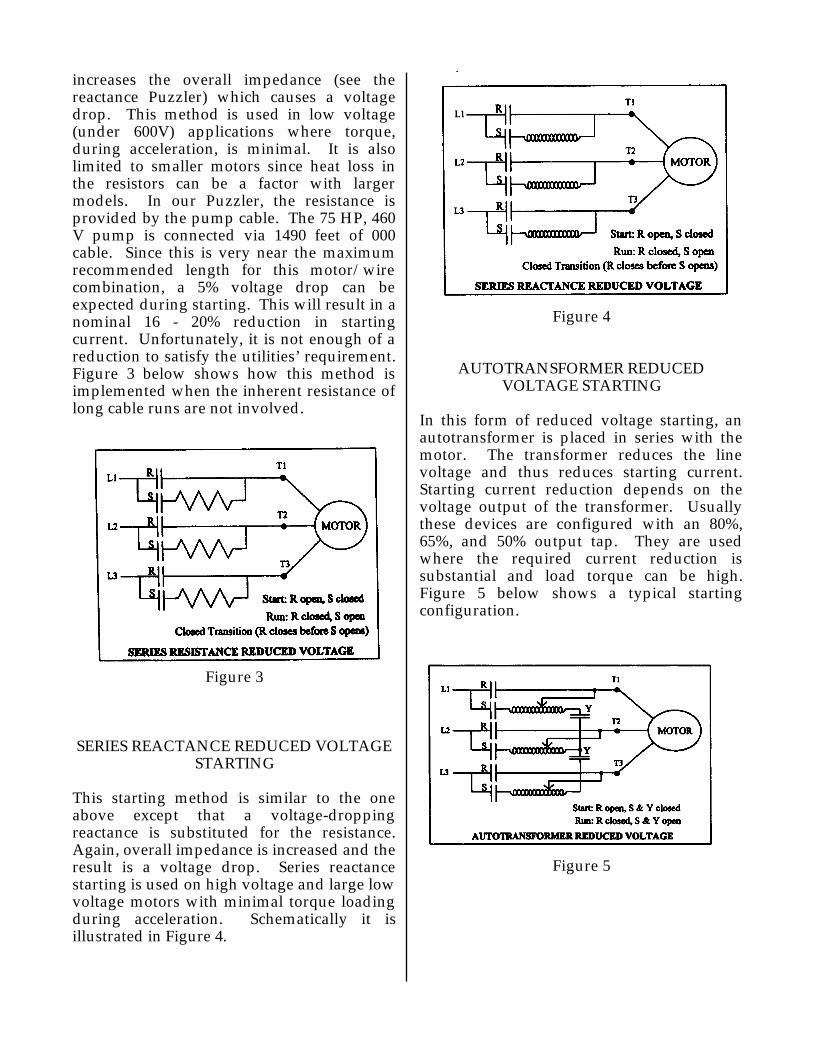
increases the overall impedance (see the reactance Puzzler) which causes a voltage drop. This method is used in low voltage (under 600V) applications where torque, during acceleration, is minimal. It is also limited to smaller motors since heat loss in the resistors can be a factor with larger models. In our Puzzler, the resistance is provided by the pump cable. The 75 HP, 460 V pump is connected via 1490 feet of 000 cable. Since this is very near the maximum recommended length for this motor/wire combination, a 5% voltage drop can be expected during starting. This will result in a nominal 16 - 20% reduction in starting current. Unfortunately, it is not enough of a reduction to satisfy the utilities’ requirement. Figure 3 below shows how this method is implemented when the inherent resistance of long cable runs are not involved.
Figure 3
SERIES REACTANCE REDUCED VOLTAGE STARTING
This starting method is similar to the one above except that a voltage-dropping reactance is substituted for the resistance. Again, overall impedance is increased and the result is a voltage drop. Series reactance starting is used on high voltage and large low voltage motors with minimal torque loading during acceleration. Schematically it is illustrated in Figure 4.
Figure 4
AUTOTRANSFORMER REDUCED VOLTAGE STARTING
In this form of reduced voltage starting, an autotransformer is placed in series with the motor. The transformer reduces the line voltage and thus reduces starting current. Starting current reduction depends on the voltage output of the transformer. Usually these devices are configured with an 80%, 65%, and 50% output tap. They are used where the required current reduction is substantial and load torque can be high. Figure 5 below shows a typical starting configuration.
Figure 5

SOLID STATE REDUCED VOLTAGE STARTING
This form of reduced voltage starting uses a solid state starter, consisting of SCR’s (silicon controlled rectifiers) to reduce the AC sine wave amplitude so that only a portion of the wave is seen by the motor. They are controlled by logic circuits that can respond to several different feedback sensors. Solid state starters are used when the rate of acceleration must be controlled or when a “soft” start (reduced current) is desired. They are available for both low and medium (4160V) voltage motors. Figure 6 illustrates a typical soft start device.
Figure 6
SOLID STATE VARIABLE FREQUENCY STARTING
Although sometimes confused with the method described above, variable frequency starting applies full voltage to the motor terminals but, at a reduced frequency via a variable frequency inverter. The initial frequency can very low and increased gradually. It is often used when full load torque is required during acceleration. They are usually too expensive to be used just as a starter, but can be justified at times because they offer the very best starting characteristics relative to the burden placed on the power supply.
So far, we have discussed starting techniques that utilize devices that are totally separate from the motor. There are, however, several
methods that can reduce starting current by changing the motor’s winding configuration.
WYE START / DELTA RUN REDUCED VOLTAGE STARTING
Technically this is not a reduced voltage technique in that the motor terminals see full voltage. The wye/delta starter connects the motor’s leads in a wye configuration during starting thus increasing the circuit’s normal reactance. The result is a decrease in voltage reflected to the stator equal to √3. Thus the current draw is reduced to about 30% of the normal starting current. Once the motor is running the starter switches the leads to a normal delta connection and full voltage is restored. This technique is used when very low starting torque is required and is seen more often in systems manufactured in Europe. Figure 7 below is that of a wye/delta starter.
Figure 7
PART WINDING STARTING
This starting method requires a motor wound specifically for this application. It is not a reduced voltage technique. These special nine lead motors use only a portion (1/2 to 2/3) of their windings during starting. Starting torque is extremely low and the motor is not expected to accelerate. Under some conditions the shaft may not even turn. In any case the starter should not remain in

the start position for more that one to two seconds because of potential heat damage to the windings. Figure 8 below shows the schematic for a part winding starter.
Figure 8
Table 1 summarizes the electrical characteristics of the various starting techniques we have discussed.
Table 1
Type Voltage% Line Amp% Torque%
Across The Line100 100 100
Series Resistance (Typ) 80 80 64
Series Reactance (80%) 80 80 64
Autotransformer80% Tap80 64 6465% Tap65 42 4250% Tap50 25 25
Solid State (Soft Start)Variable Variable Variable
Solid State VFD100 Variable TO 100
Wye / DeltaLine / √3 30 30
Part WindingLow Speed100 50 50High Speed100 70 50
761 Ahua Honolulu, HI 96819
Phone 808.536.7699 Fax 808.536.8761www.pacificliquid.com

The Changing Voltage Puzzler
a Solaray Company
240V
240V240V 208V 208V
208V
THREE PHASEDISCONNECT
THREE PHASEDISCONNECT
120V 120V 120V 120V 120V120V
A mechanical contractor ran into the situation shown above while hewas replacing some booster pumps in a large Waikiki hotel. In one ofthe older buildings the three phase supply voltage was 240V. In anewer section, however, he found the supply voltage to be 208V. Inboth areas all legs read 120V when measured to ground. Why doesthe supply on the right read 208V leg to leg? Are not the legsadditive? How can 120 + 120 = 208?
PL&A CAD
761 AHUA HONOLULU, HI 96819

THE CHANGING VOLTAGE PUZZLER
THREE PHASE CONNECTIONS
Joe Evans, Ph.D
Before we discuss the differing voltages observed in our Puzzler, lets take a look at another apparent voltage discrepancy. You have probably noticed that motor nameplate voltage and the service voltage provided by a utility are not always in agreement. Although the numbers can be quite different, they are legitimate and arise from differing rating methods.
Two common low voltage services available today are 240V and 480V. In most instances a utility is required to deliver power to a user within in a range of plus or minus 5% of the stated service voltage. For 480 volt service the acceptable range is 456V - 504V and for 240 volts it is 228V - 252V. In practice, however, this range is usually much narrower and is typically 1 to 2%.
NEMA motor manufacturers, on the other hand, follow an unwritten standard and rate their products at 95.8% of the stated service voltage. Therefore a motor rated for 480V service will show a nameplate voltage of 460V and those designed for 240V display 230V. Motors wound specifically for 208V service are usually nameplated at 200V. Unless otherwise indicated on the nameplate, a motor can operate at 95.6% of its nameplate voltage without reducing its service factor. Acceptable low voltages for 460V and 230V motors are 440V and 220V respectively. When a tri-voltage or 230V motor is operated at 208V, its service factor is reduced to unity. Hopefully this explains why 200/208, 220/230/240, and 440/460/480 volt ratings are used interchangeably throughout our industry.
Now, on to our puzzler. “A chicken in every pot and an eagle in every pocket” or so went one slogan during the Great Depression. Had Thomas Edison won the battle over
power distribution, we could have added “and a power plant on every corner”. Edison was a dedicated proponent of DC power and fought the use of AC bitterly. He invented the incandescent lamp in 1879 and began immediately to develop a power generating and distribution system to promote it. His first power plant opened in New York City in 1882 and several others were built over the next few years. Most of the power generated by Edison’s plants went to lighting customers; however, DC motors were in use in industry by the 1880’s. Although Edison’s efforts were a limited financial success, it was soon recognized that DC systems suffered heavy power losses in transmissions over any distance.
The great advantage of AC power is that voltage can be easily stepped up or down by use of a transformer. This advantage is due to the relationship of the volt and amp. Power in watts is equal to volts times amps. If we want to transmit 1,000,000 watts (one megawatt) from one point to another, we can use any number of volt - amp combinations. For example a current intensity of 1000 amps at 1000 volts equals one megawatt. 100 amps at 10,000 volts is also a megawatt. Why not 10 amps at 100,000 volts? When transmitting power over long distances utilities use the highest voltage practical because the energy expended (heat) in maintaining current flow increases as the square of the current intensity. In order to keep such an energy loss to a minimum, a much larger conductor is required to transmit the same amount of power when the current component is high. This, of course, leads to higher cost and weight. Once AC power reaches its point of use it is then stepped down to a more usable voltage.
Like the ac motor, a transformer is an inductive device. It uses power flowing through a coil of wire to “induce” a voltage in a nearby coil. The voltage that exits the secondary is proportional to the number of turns (coils) on the primary (incoming) and secondary (outgoing) side of the transformer. For example, consider a simple

single phase transformer with 10 turns of wire on its primary and 100 turns about its secondary. If we apply 10 volts to the primary, the secondary will produce 100 volts (a factor of 10X). Reverse the number of primary and secondary turns and the 10 volts applied to the primary becomes 1 volt at the secondary (a factor or 0.1X). Since power in watts remains constant (ignoring losses) current varies inversely with voltage. In the first example, if the primary current intensity is 1 amp @ 10V then the secondary current intensity will be 0.1 amp at 100V. The power in watts (volts x amps) is the same on both sides of the transformer. The same holds true for the second example.
A three phase transformer is simply three, single phase transformers wound about a common metal core. In fact it often consists of three individual single phase units. The figure below illustrates a simple three phase transformer. The primary and secondary windings for each phase are wound about separate legs of the core. The start of each of the windings is identified by the • and is required to insure proper phasing when the three phases are connected.
PH A PH B PH C
PRIMARY
SECONDARY
Again, like the ac motor stator, the primary and secondary windings of a transformer may be either delta and wye connected.
The three most common winding configurations and their typical uses are listed below.
DELTA Primary to DELTA SecondaryIndustrial installations
DELTA Primary to WYE SecondaryCommercial and light industrial installations
WYE Primary to DELTA SecondaryHigh voltage transmission
The figures below show the secondary of a three phase transformer (or output of a generator) connected in three wire Wye and Delta configurations. As you can see line to line voltages among the three phases are 208V for the Wye connection and 240V for the Delta connection. If, however, a neutral wire were added to both connecting schemes, the line to neutral (phase voltage) measurement will be 120V for all phases regardless of whether they are Wye or Delta connected. If this is the case, why isn’t the sum of the Wye’s line to line voltages 240V, as it appears to be in the Delta connection?
WYESECONDARY
208V
208V
208V
A
C B
a
bc
N
DELTASECONDARY 240V
240V
240V
A
C
B
c
a
b
Actually, in the traditional sense, neither “adds” up to 240V but we will get to that a little later.
The three phase curve seen on the next page shows the output of the simple transformer seen in adjacent column. If you look carefully you will detect two important points. First, since the three wave forms are 120˚ out of phase with one another, the algebraic sum of the instantaneous voltages (or current for that matter) is always zero.

Second, at no time are the three phases all negative or all positive.
PH A PH B PH C
+170 V
-170 V
0
120˚ 120˚
The phase or phasor diagram below depicts the three voltages in a vector format. It shows phase voltages of 120V (RMS) 120˚ apart. The length of each vector is proportional to the voltage.
VC = 120 (120˚)
VB = 120 (-120˚)
VA = 120 (0̊ )
Although the Wye and Delta connection schematics on the previous page show how the phases are connected, they don’t explain the variation between the line to line voltages. If the phase voltages are not additive their variation must have something to do with their vectors since vector length is proportional to voltage.
The figures at the top of the right hand column are phase diagrams of the two connection schemes. Since the top one appears a bit more complex, lets start with simpler Delta configuration.
VCB
VBAVAC = 208 (-30˚)
30̊
30̊60̊
VAa = 120 (0˚)
-VCcVBb
-VAa
VCc -VBb
WYE PHASOR
VC = 120 (120˚)
VB = 120 (-120˚)
VA = 120 (0̊ )
120˚
60˚
60˚120˚
DELTA PHASOR
The three solid arrows spaced 120˚apart represent the Delta connection phase voltages and the angle at which they occur. The circle plots the phase voltage through a full 360 electrical degrees. In order to compute the the voltage (vector) that is generated at any point between the phases, a parallelogram must be constructed. In this example the outside corner of the parallelogram falls on the circle mid way between phases A and B. The dashed arrow is the vector for this point and its length indicates a voltage of 120V. In fact if we construct a parallelogram for any point between any of the phases, its corner will always fall on the circle. Therefore the voltage that arises due to the combined influence of any two of the phase angles (ie transformer or generator coils) will always equal the phase voltage of 120V. Thus the voltage produced by any two Delta connected leads will be the sum of the vectors or 240V.
The simplicity of the Delta phasor is due to its closed loop geometry and the fact that the instantaneous and phasor voltage sums are zero. Not so with the Wye connection. You can see from its rather complex phase diagram that much more is happening.
The Wye connection gets its name from the junction of the three coils which forms a “Y” (often called a star) shape. This geometry causes the line voltages to lag (or lead depending upon the reference point) the phase voltages by 30˚. This shift results in the line vector labeled VAC in the Wye phasor shown on the previous page. The construction of a parallelogram extending from vectors VAa and -VCc (which is VCc flipped 180˚) will determine the length of the line voltage vector. As you can see, this parallelogram and resulting vector VAC forms two isosceles triangles. If we project a line perpendicular from the base of vector VAC to the end of vector VAa the upper isosceles triangle is divided into two identical right triangles. It also divides VAC exactly in half. We can now use a simple trigonometric relationship to calculate the length of the line vector.
Adjacent side = cos ø x hypotenuse0.5VAC = cos 30˚ x VAa = 0.866 x VAaVAC = 0.866VAa / 0.5 = 1.732VAa
Thus the line voltage of a Wye connected system is 1.73 times larger than the phase voltage. For example the phase voltage of a 230V Wye system is 133V, while that of a 480V Wye is 277V.
Four wire Wye systems are popular in light industrial applications because they can provide three different voltages that can be used for a variety of devices. 120V, single phase current is available between any line and neutral; 208V, single phase is available between any two of the lines; and 208V, three phase current is available across all three lines. The line current of a Wye system is equal the phase current. If a 10A load were connected to lines B and C of the Wye diagram on page two, 10A will flow through line B, Line C, Phase Bb, and Phase Cc.
But wait a minute here. Is the Wye system less efficient than the Delta. It would certainly appear so because its power output appears lower than that of the Delta system. For example, if a 10A current was induced in the secondary coils of a Wye and Delta transformer or generator, the power (in watts) produced will be equal to Volts x Amps. For the Wye this equals 2080W but the same computation for the Delta equals 2400W.
Well, the conservation laws are at work yet again. Inspection of the Delta diagram on page two reveals that line current is greater than phase current because each line carries the current from two coils. It turns out that line current for a Delta system is 1.732 times that of the phase current. This geometry gives rise to a Delta current phasor that is strikingly similar to that of the Wye voltage phasor. And, it is probably no surprise that the Wye current phasor looks much like the Delta voltage phasor.
These line voltages and currents give rise to the following relationships which hold true (ignoring power factor) for both Wye and Delta three phase circuits.
Amps = Watts / (Volts x 1.732)
Volts = Watts / (Amps x 1.732)
Watts = Volts x Amps x 1.732
761 Ahua Honolulu, HI 96819Phone 808.536.7699 Fax 808.536.8761
www.pacificliquid.com
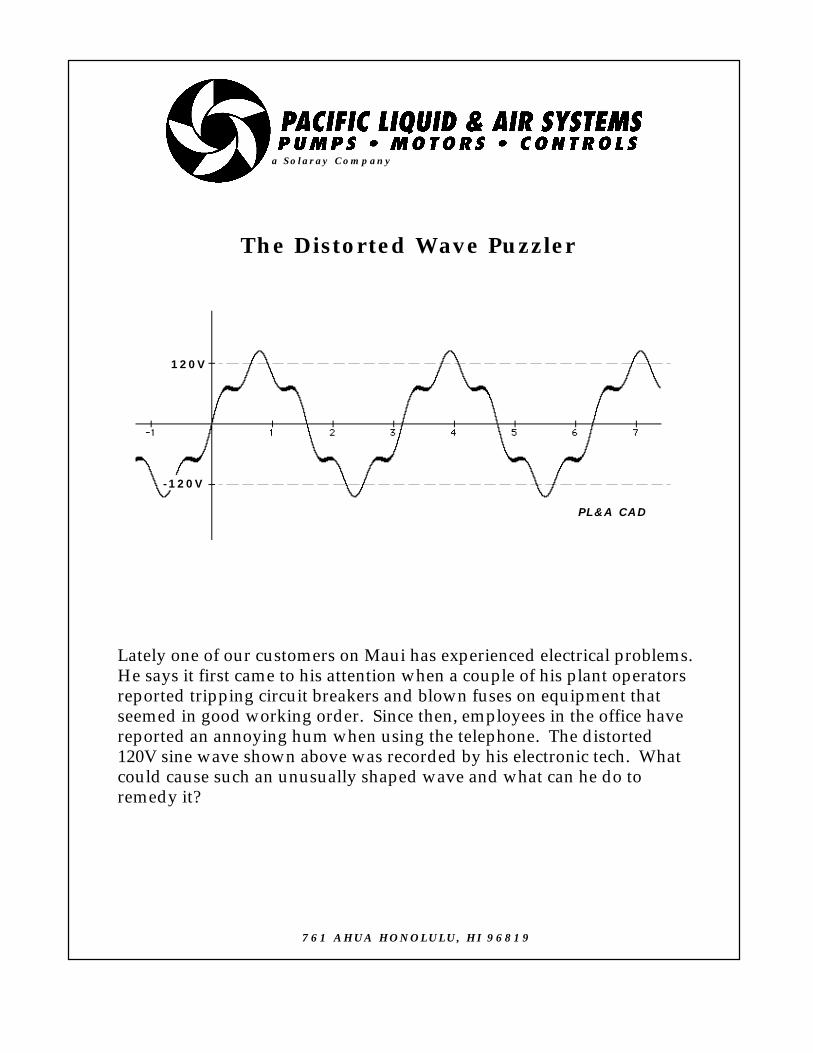
The Distorted Wave Puzzler
a Solaray Company
PL&A CAD
Lately one of our customers on Maui has experienced electrical problems.He says it first came to his attention when a couple of his plant operatorsreported tripping circuit breakers and blown fuses on equipment thatseemed in good working order. Since then, employees in the office havereported an annoying hum when using the telephone. The distorted120V sine wave shown above was recorded by his electronic tech. Whatcould cause such an unusually shaped wave and what can he do toremedy it?
120V
-120V
761 AHUA HONOLULU, HI 96819

THE DISTORTED WAVE PUZZLER
HARMONICS
Joe Evans, Ph.D
There was a time when a customer could count on receiving electrical power from the utility in the form of a pure sinusoidal wave. In recent years that wave has lost some of its purity.
“Dirty” power is an expression used to describe any number of voltage and current contaminations of the pure 60hz sine wave. They can be anything form short term transients to continuous distortions and can arise from within a customer’s location or from some source outside. Usually the outside source is another location that is contaminating the utility’s distribution system.
From the perspective of current usage there are two types of electrical loads - linear and nonlinear. Linear loads use pure sine wave current and include incandescent lighting, heating, and most inductive devices. Nonlinear loads “chop” up the sine wave and utilize only portions of it. Solid state switching devices such as variable frequency drives (VFD) and power supplies are major components of nonlinear loading.
The type of contamination our Puzzler customer is experiencing is known as harmonic distortion. Harmonics are a steady state phenomenon and should not be confused with short term transients such as voltage spikes and sags. They are generated by nonlinear loads which draw power in a non-sinusoidal manner. Although some linear loads, including motors and transformers, can also contribute slightly to overall harmonic distortion the vast majority can be attributed to nonlinear devices and their recent proliferation in industry. Since harmonic distortion can cause serious operating problems it is important that we
understand its causes, consequences, and remedies.
What is a harmonic? Think about music for a moment. Our ear has no trouble distinguishing between the very same tone played on a piano or guitar because each has a characteristic sound that differs in something we call quality or timbre. Musical sounds are often composed of many frequencies as opposed to a single one. For example, when a guitar or piano string vibrates it does so not only from end to end but also between nodes which are points located along its length. The figure below shows a string vibrating in such a manner.
Figure 1
These intermediate vibrations (frequencies) are known as partial tones. The lowest frequency (fundamental or end to end vibration) determines the pitch. Partial tones (node to node vibrations) are whole multiples of the fundamental frequency and are called harmonics. A tone that has three times the frequency of the fundamental is called a third harmonic. Figure 1 is an example of a third harmonic. It is the combination of these partial tones and the fundamental tone that gives a musical note its characteristic quality.
In the case of electric power, a harmonic is a wave that possesses a frequency that is a multiple of the power frequency. But, unlike music quality, harmonics detract rather than add to the quality of electrical power.
Figure 2, seen on the next page is a graph showing both a fundamental 60hz power sine wave and its 300hz, fifth order harmonic. As you can see there are five harmonic cycles for each 60hz cycle. The distorted wave form shown in the Puzzler is the result one sees when the two wave forms in Figure 2 are combined.

Figure 2
If you want to see this in real time, use your PC’s graphing calculator to plot:
Sin X = 0.2 Sin 5X.
This will plot the curves shown above. Then plot:
Y = Sin X + (0.2 Sin 5X)
and you will see the distorted curve shown in the Puzzler. (If you don’t have a Mac you can use a hand held graphics calculator or you can wait for Windows 2002.)
The dominant harmonics created by nonlinear three phase loads include the 5th, 7th, 11th, and 13th while single phase loads consist primarily of the 3rd and higher multiples of three.
As described in the Puzzler harmonic distortion can cause blown fuses and tripped circuit breakers. It can also reduce motor and transformer life. It increases RMS (root mean square) voltage peaks which can place extra stress on insulation. Harmonics also increase the RMS current which usually results in higher operating temperatures for many devices.
One way to reduce or even eliminate the harmonic distortion caused by solid state switching devices is to install an isolation transformer before the causative device. Unfortunately their expense makes this
impractical. A economical alternative is the line reactor, illustrated in figure 3 below.
PHASE
ABC
Figure 3
The line reactor is usually a simple inductor that acts as a current limiting device. When the power wave is chopped, voltage and current spikes can be produced. Inductive reactance within the reactor resists the flow of high frequency harmonics thus reducing these spikes. Basically, as frequency increases so does the resistance.
A line reactor can eliminate or reduce the aforementioned operating problems associated with nonlinear loads. They can also reduce VFD “tripping” which can occur when the utility switches Power Factor correction capacitors onto the power grid.
Harmonically compensated reactors, those with capacitors in the circuit, can be specifically tuned to handle a waveform’s harmonic content. These “harmonic filters” can be used on either the line or load side of a VFD. On the line side they serve a bidirectional function. They not only filter power to the VFD but also filter out any distortion produced by the drive that may find its way back into the users electrical distribution system. On the load side they act as a current limiting device and protect the VFD in case of short circuit conditions. They slow the rate of current rise during a short

circuit which allows the VFD time to react safely. They also absorb motor surges, due to high torque loads, that can cause nuisance tripping of the drive.
Some vendors, such as Commonwealth Sprague, offer harmonic filters that not only reduce harmonics, but also provide power factor correction as well. An example, known as a shunt harmonic filter is shown in figure 4.
PHASE
ABC
Figure 4
This type of filter combines power factor correction capacitors with a line reactor. It provides power factor correction at the fundamental frequency and becomes an inductor at higher (harmonic) frequencies. Since it is not capacitive at these higher frequencies, an electrical distribution system cannot resonate the higher frequencies and thus magnify their voltages and currents.
For more information on this topic, set your web browser to power and harmonics.
761 Ahua Honolulu, HI 96819Phone 808.536.7699 Fax 808.536.8761
www.pacificliquid.com

The Syntax Puzzler
115VAC
The schematic diagram shown above is that of an alarm circuit. Itwas designed by a somewhat overly cautious engineer. (Is there ahyphen in anal retentive?) Please list the conditions that will causean alarm.
B C
D
E
F
GH
IR1
R2
J
K
R3 L
M
R4 R5
NO
LEGEND:A - O -- N/O SPST SWITCHES R1 - R3 -- N/C SPST RELAYS R4 - R5 -- N/C DPDT RELAYS
A
ALARM N
N
N
N
N
NN
a Solaray Company
PL&A CAD
761 AHUA HONOLULU, HI 96819
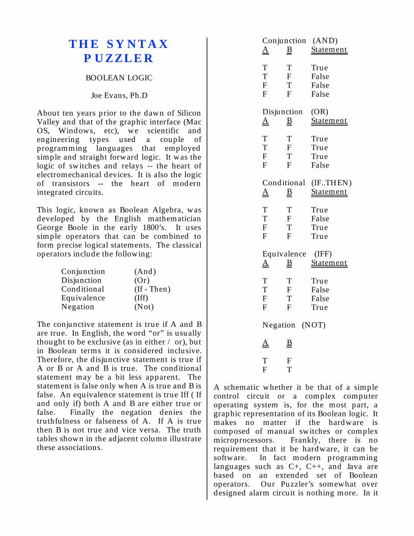
THE SYNTAX PUZZLER
BOOLEAN LOGIC
Joe Evans, Ph.D
About ten years prior to the dawn of Silicon Valley and that of the graphic interface (Mac OS, Windows, etc), we scientific and engineering types used a couple of programming languages that employed simple and straight forward logic. It was the logic of switches and relays -- the heart of electromechanical devices. It is also the logic of transistors -- the heart of modern integrated circuits.
This logic, known as Boolean Algebra, was developed by the English mathematician George Boole in the early 1800’s. It uses simple operators that can be combined to form precise logical statements. The classical operators include the following:
Conjunction (And)Disjunction (Or)Conditional (If - Then)Equivalence (Iff)Negation (Not)
The conjunctive statement is true if A and B are true. In English, the word “or” is usually thought to be exclusive (as in either / or), but in Boolean terms it is considered inclusive. Therefore, the disjunctive statement is true if A or B or A and B is true. The conditional statement may be a bit less apparent. The statement is false only when A is true and B is false. An equivalence statement is true Iff ( If and only if) both A and B are either true or false. Finally the negation denies the truthfulness or falseness of A. If A is true then B is not true and vice versa. The truth tables shown in the adjacent column illustrate these associations.
Conjunction (AND)A B Statement
T T TrueT F FalseF T FalseF F False
Disjunction (OR)A B Statement
T T TrueT F TrueF T TrueF F False
Conditional (IF..THEN)A B Statement
T T TrueT F FalseF T TrueF F True
Equivalence (IFF)A B Statement
T T TrueT F FalseF T FalseF F True
Negation (NOT)
A B
T FF T
A schematic whether it be that of a simple control circuit or a complex computer operating system is, for the most part, a graphic representation of its Boolean logic. It makes no matter if the hardware is composed of manual switches or complex microprocessors. Frankly, there is no requirement that it be hardware, it can be software. In fact modern programming languages such as C+, C++, and Java are based on an extended set of Boolean operators. Our Puzzler’s somewhat over designed alarm circuit is nothing more. In it

the operators And, Or, Iff, and Not are employed singularly and in combinations to energize the alarm. If we replace the word “true” with “on”, the logic of the circuit will become apparent.
Lets begin at top of the circuit and see what conditions will cause an alarm. The alarm will sound if:
If A is onIf B and C are onIf D or E (or D & E) is onIf F or G (or F & G) and H are onIf I is not onIf J is on but K is not onIf L and M are not onIff N & O are on or N & O are offAny combination above
In the case of transistor and integrated circuit logic we tend to speak of “gates” rather than switches or relays. The conjunctive becomes an AND gate while the disjunctive is an OR gate. When these are combined with the negation they become NAND and NOR gates.
Transistors are composed of a thin layer of silicon dioxide (or other derivatives) fused to an insulating substrate. These silicon compounds are members of a family of substances know as semiconductors. Normally, they are non conducting but, when a current is applied, their structure is altered and they become conductive. If, for example, a continuous current were applied a transistor will allow a signal to pass through. When the current is removed, the signal stops. In other words, it can be a simple on / off switch. If, on the other hand, a current of varying amplitude were applied the resulting signal would also vary in amplitude. In this case it acts as an amplifier. Both of these functions are found in control logic. The on / off function is apparent in our puzzler. Examples of amplification include pressure transducers and flow meters.
An integrated circuit (IC) concentrates thousands of transistors on a single chip. When these chips are incorporated into a
Programmable Logic Controller (PLC) we gain the flexibility of combining dozens of control functions in a space not much larger than a single electromechanical relay.
761 Ahua Honolulu, HI 96819Phone 808.536.7699 Fax 808.536.8761
www.pacificliquid.com

The Grounded Pump Puzzler
One of our pump manufacturers was vacationing on maui recently andhad an opportunity to visit the new Ocean Center. While there, he noticedone of his cast iron pumps pumping water from a tidal pond anddischarging into the main aquarium. He also noticed that there was alarge copper cable running from the case bracket to a rod in the sandseveral yards away. A maintenance worker told him that, because thepump was pumping salt water, it had to be grounded. Why would oneground a salt water pump?
SEAWATER
SAND
CONCRETESLAB
a Solaray Company
PL&A CAD
761 AHUA HONOLULU, HI 96819
THE GROUNDED PUMP PUZZLER
CORROSION
Joe Evans, Ph.D
About 900 years before Newton formulated his universal gravitational theory the Greek philosopher, Aristotle, espoused something very different. He believed that all things had a natural place in the universe and therefore, any object that fell to the earth did so because it had a “need” to return to its natural place. He further theorized that heavier objects would fall faster than lighter ones because they had an even greater need to return. We know now that his theory was a bit off the mark but, had he adapted it to corrosion it could have described the process quite well.
Corrosion, like biological and organic decomposition, is a naturally occurring process. The question is not if it will occur, it is how quickly. Steel, for example, is a man made material that is manufactured from iron ore. Because energy is added during the manufacturing process the end product is unstable and, given the opportunity, it will return to its natural state. Now, whether it truly “needs” to resume its original identity is a question I shall leave to the psychologists.
Corrosion is an electrochemical process that requires that five conditions be present if it is to occur. There must be:
1) A supply of oxygen
2) An anode (where corrosion occurs)
3) A cathode
4) An electrolyte that permits the flow of ions and electric current
5) A conductive path for the return flow of current
The anode and cathode are electrically distinct areas that exhibit properties similar to the poles of a battery. They may be different structures (i.e. two different pieces of metal) or they may be two different locations within the same structure. The anode is the location or structure that suffers metal loss during corrosion. An electrolyte can be almost any material that contains moisture. Air, water, soil, and concrete are but a few common examples. Its purpose is to provide a path for the flow of metal ions between the anode and cathode. It also provides a conduit for the electrical current that is generated by ion flow. The greater its conductivity, the better its electrolytic capability. Salt water, for example, provides a much better path for ion and current flow than does fresh water and therefore hastens the corrosion process. In a similar fashion, the metal itself provides a return path for the flow of current from the cathode back to the anode.
Corrosion chemists refer to the different environments where these conditions can occur as “corrosion cells”. Three types of corrosion cells are common in pumping applications.
1) Dissimilar metal cells - Commonly referred to as galvanic corrosion, these cells occur when two different metals contact one another in a common electrolyte.
2) Dissimilar electrolyte cells - This type of corrosion occurs when a single structure passes through an electrolyte of varying properties.
3) Differential aeration cells - These cells occur commonly in soils where a single structure passes through areas of differing oxygen concentration.
Corrosion, if left unchecked, can be an extremely efficient and swift process. For example, a current of a single ampere flowing from a steel pipeline into the soil can consume twenty pounds of pipe in just a year’s time. Fortunately, it can be prevented if any one of the required conditions can be eliminated.

Probably the most common method of eliminating one of the required conditions is to coat the surface of a metal. A good coat of paint or epoxy can electrically isolate the surface of a metal structure from a potential electrolyte and therefore prevent it from corroding. Some of the two part epoxies available today can make cast and ductile iron pumps quite corrosion resistant, even in salt water applications. In fact the product of corrosion itself can, in some cases, provide a protective coating. The iron oxide (rust) formed as iron or steel corrodes is not a very good conductor. But, unfortunately, it does not adhere very well and tends to flake away thus exposing the surface to additional degradation. Aluminum oxide, on the other hand, is an extremely hard and durable substance that does a good job of protecting aluminum surfaces from further corrosion.
Another method of corrosion prevention that has been used for well over one hundred years is passive cathodic protection. I said earlier that it is the anode that suffers metal loss during corrosion. If we transform a structure that is normally an anode into a cathode and let some other structure become the anode, we can protect the original structure. Cathodic protection does this by adding a sacrificial metal that gives up electrons more easily than the metal to be protected and thus becomes the anode. This allows the original structure to undergo a major life change (to that of a cathode). The process is termed passive because current flow between the anode and cathode occurs naturally and is due to “galvanic” action. It is an example of a dissimilar metal corrosion cell and illustrates how we can use a normal corrosion process to selectively protect a structure that would otherwise undergo corrosion.
The most common form of passive cathodic protection is the galvanized coating of zinc we find on sheet metal. Since zinc is the less “noble” (looser electrons) metal, it becomes the anode and is sacrificed in order to preserve the primary metal. The “grounded” pump in our Puzzler is also an example of this process. The ground wire
referred to by the maintenance worker actually serves to connect the pump case to a zinc anode buried, at or below the water level, near the shore. Since both metals are in contact with a common electrolyte, the zinc becomes the anode and protects the surfaces of the cast iron pump from sea water corrosion. In submersible pump installations we can attach a sacrificial anode directly to the pump body and achieve the same results in a less complicated manner. In either case the anode, depending upon its rate of decomposition, must be renewed periodically. The figure below illustrates the chemical and electrical aspects of the passive cathodic protection process.
ZINCANODE
CAST IRONCATHODE
CURRENT
ELECTRONS
OH
CURRENT
ELECTROLYTE
Zn+
Another common type of cathodic protection is “impressed current” cathodic protection. Instead of relying on a natural flow of current between the sacrificial anode and cathode, an external direct current is applied to both. The impressed current makes the anode, regardless of its nobility, more positive than the structure that is to be protected. An advantage of this method is that almost any conductive material may used as an impressed current anode. In fact, materials with very low consumption rates are the most desirable since they require less frequent replacement.
A relatively recent twist on impressed current cathodic protection is known as “capacitive discharge oxidation interference” (CDOI). This system uses a capacitor bank to effect a bulk transfer of electrons through an
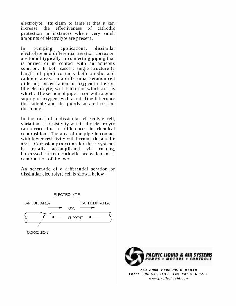
electrolyte. Its claim to fame is that it can increase the effectiveness of cathodic protection in instances where very small amounts of electrolyte are present.
In pumping applications, dissimilar electrolyte and differential aeration corrosion are found typically in connecting piping that is buried or in contact with an aqueous solution. In both cases a single structure (a length of pipe) contains both anodic and cathodic areas. In a differential aeration cell differing concentrations of oxygen in the soil (the electrolyte) will determine which area is which. The section of pipe in soil with a good supply of oxygen (well aerated) will become the cathode and the poorly aerated section the anode.
In the case of a dissimilar electrolyte cell, variations in resistivity within the electrolyte can occur due to differences in chemical composition. The area of the pipe in contact with lower resistivity will become the anodic area. Corrosion protection for these systems is usually accomplished via coating, impressed current cathodic protection, or a combination of the two.
An schematic of a differential aeration or dissimilar electrolyte cell is shown below.
ELECTROLYTE
CATHODIC AREAANODIC AREA
CORROSION
IONS
CURRENT
761 Ahua Honolulu, HI 96819Phone 808.536.7699 Fax 808.536.8761
www.pacificliquid.com
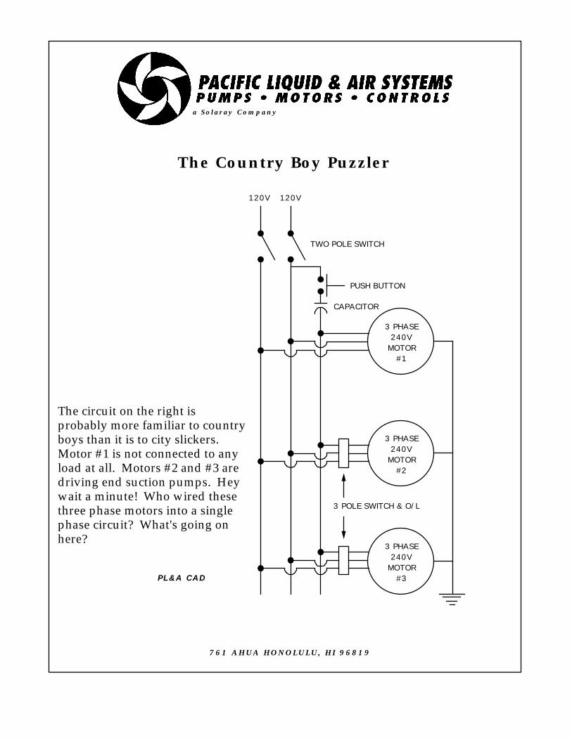
The Country Boy Puzzler
3 PHASE240V
MOTOR#1
3 PHASE240V
MOTOR#2
3 PHASE240V
MOTOR#3
120V 120V
PUSH BUTTON
CAPACITOR
TWO POLE SWITCH
3 POLE SWITCH & O/L
The circuit on the right isprobably more familiar to countryboys than it is to city slickers.Motor #1 is not connected to anyload at all. Motors #2 and #3 aredriving end suction pumps. Heywait a minute! Who wired thesethree phase motors into a singlephase circuit? What's going onhere?
a Solaray Company
PL&A CAD
761 AHUA HONOLULU, HI 96819

THE COUNTRY BOY PUZZLER
PHASE GENERATOR
Joe Evans, Ph.D
The reason country boys may recognize this circuit and city slickers may not is due to the fact that three phase power is (or was) not always readily available outside of industrial or metropolitan areas. This was especially true back in the fifties and sixties when this type of circuit flourished.
The circuit, of course, is that of a home made phase generator. These units and their commercial cousins add a third phase to 240V single phase current. They were and still are used in circumstances where three phase equipment is required but three phase power is not available. Often, due to horsepower and speed limitations, mechanical equipment is provided with three phase motors only. Today, we can generate a third phase (leg) electronically but these old “rotary” converters have survived the test of time. Lets take a look at how they work.
Interestingly enough, any 240V three phase motor will run on 240V single phase power as long as two important conditions are followed. First the motor cannot be loaded beyond 2/3 of its three phase rating. Second, since single phase current cannot start a three phase motor, some other method of starting must be provided. On low RPM motors (1200 RPM and fewer) you can actually “kick” start them by spinning the shaft with the sole of your shoe. Our circuit illustrates a starting method that is still simple, but a bit more sophisticated. A momentary contact switch and a capacitor provide a temporary surge of power to the third leg which is enough to get the motor rotating. Now the interesting stuff begins to happen.
Once motor #1 is started and the push button is released, the motor will continue to run on two legs of 120V power. Although single
phase power is actually running the motor, a voltage is induced in the unpowered coils of the stator’s third leg. In other words, the motor is acting as a generator and is, in fact, generating the third leg needed for three phase power. Since the motor is completely unloaded, little of the single phase power is required to keep it turning. Since motors #2 and #3 are connected to the circuit in the same manner as motor #1, they can run on the three phase power provided by the two 120V single phase legs and the third 120V leg generated by motor #1.
Motor #1 is called an “idler” and its purpose is to generate the third leg necessary for three phase power. However, once running in an unloaded condition, any of the motors in the Puzzler circuit could provide the third leg. In fact if a loaded motor begins to bog down the idler’s capability to generate the third leg (ie overload its generating capacity), another motor on the circuit can be “idled” and provide additional power to the third leg of the circuit. Taking it one step further, when any two or more of the motors shown in the Puzzler circuit are idling, they are all running on three phase current!
Obviously the efficiency of the system described above is quite a bit lower than one utilizing commercial three phase current. There are times; however, when the cost or the availability of the motorized equipment outweighs the cost of power.
761 Ahua Honolulu, HI 96819
Phone 808.536.7699 Fax 808.536.8761
www.pacificliquid.com
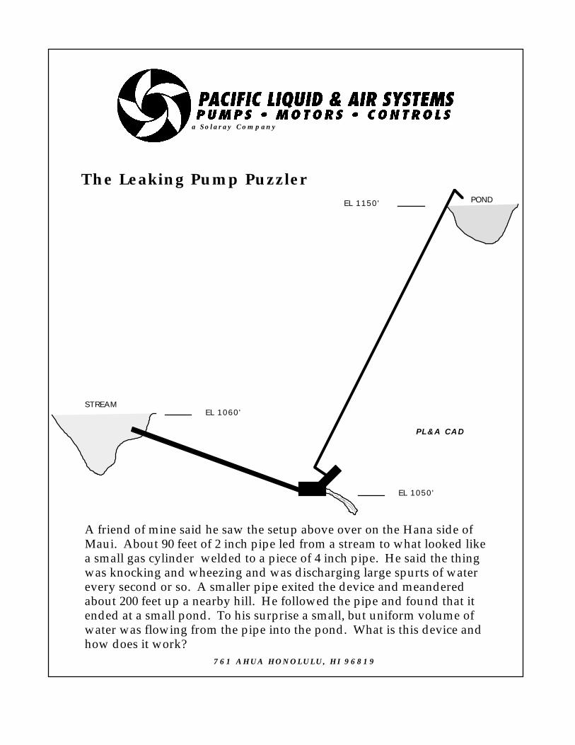
The Leaking Pump Puzzler
EL 1050'
EL 1060'
EL 1150'
STREAM
POND
A friend of mine said he saw the setup above over on the Hana side ofMaui. About 90 feet of 2 inch pipe led from a stream to what looked likea small gas cylinder welded to a piece of 4 inch pipe. He said the thingwas knocking and wheezing and was discharging large spurts of waterevery second or so. A smaller pipe exited the device and meanderedabout 200 feet up a nearby hill. He followed the pipe and found that itended at a small pond. To his surprise a small, but uniform volume ofwater was flowing from the pipe into the pond. What is this device andhow does it work?
a Solaray Company
PL&A CAD
761 AHUA HONOLULU, HI 96819

THE LEAKING PUMP PUZZLER
HYDRAULIC RAM
Joe Evans, Ph.D
The device moving water up hill in the Puzzler is a Hydraulic Ram. Like the Pelton Wheel it is an impulse device. The Ram “pump” uses the energy of a large volume of water falling a small height to lift a smaller amount of that water to a much greater height. Where ever a fall of water can be obtained, the Ram can can provide a cheap, simple, and reliable means of raising water to considerable heights.
The Ram was invented in the late seventeen hundreds in England. It was greatly improved by the Montgolfier brothers (of hot-air balloon fame) and was in widespread use, both in Europe and the USA, by the early eighteen hundreds. Rams have been designed to pump up the 50,000 gallons per day and produce discharge heads of over 300 feet. Typical Rams available today range from 700 - 1800 gpd for a one inch model to 1000 - 10,000 gpd for a three inch model. For those of us who appreciate simplicity, the Hydraulic Ram is an eloquent machine.
The design of the Ram has changed very little since its invention. Below is a drawing of the original machine. Its operation is elegantly simple.
Water enters the Ram from the supply or “drive” pipe, flows through it, and discharges through the upturned end on the left. Inside
the horizontal body of the ram is an iron ball (possibly a cannon ball). The flowing water accelerates the iron ball which, in turn, moves with increasing velocity towards the discharge. Since the ball is too large to exit the discharge, it seats itself and acts as a quick closing valve. This produces a water hammer effect that sends a high pressure shock wave back towards the inlet. A portion of this high pressure water enters the air chamber through a one way valve and then makes it way into the discharge pipe. When the pressure surge in the Ram subsides the one way valve closes, the ball rolls back to the right side of the Ram, and and the cycle starts again. This cyclic pumping action produces the characteristic beating sound heard during operation. The pumping phases are often referred to as acceleration, delivery, and recoil.
The modern Ram works on the very same principles as the original. As seen below, the only difference is that the iron ball and curved discharge have been replaced with a waste or impulse valve. In the modern Ram, water accelerating past the waste valve drags it until it slams shut. Again a high pressure shock wave is created that delivers high pressure water into the air chamber. When the air chamber delivery valve closes, the remaining water in the drive pipe recoils against it creating a low pressure area that allows the waste valve to reopen. And, as before, the cycle begins again.
For more than one hundred twenty-five years, the Ram was a major player in the water pumping arena. They were seen

providing water for industry, farms, and towns. The advent of the electric pump caused a decline in the use of Rams, but they are on the come back. And well they should be. They are the simple, low cost, and environmentally friendly way to move water up hill when a source of falling water is available. The so called “waste” water is not really wasted. It simply returns to the steam or river from which it came.
If you are interested in information about rams that are commercially available, several web sites exist. Just search using the key words hydraulic and ram.
761 Ahua Honolulu, HI 96819
Phone 808.536.7699 Fax 808.536.8761www.pacificliquid.com

The Air Lock Puzzler
The sump pump shown above is pumping up a short rise to a 4" gravity mainthat services several homes. On occasion, the pump will air lock and has to bemanually primed before it will pump again. A single, wide angle float switchcontrols the pump. In the off (down) position the float, and therefore thewater level, is well above the pump's discharge. If the float is shutting thepump off at the proper level, what could be causing it to air lock?
a Solaray Company
PL&A CAD
761 AHUA HONOLULU, HI 96819

THE AIR LOCK PUZZLER
SIPHONS
Joe Evans, Ph.D
A common problem with submersible sump and sewage pumps is air locking. It occurs most often when the control floats are set improperly and allow over pumping of the basin. This allows air to enter the pump’s volute, become entrapped, and then prohibit the pump from priming during the next pump down cycle. Many pumps are designed with a small hole in the back of the volute that allows trapped air to escape; however, these holes tend to plug rather quickly.
Air locking can also occur upon installation or reinstallation of pumps with integral spring loaded check valves. These valves do not allow the normal release of air as the pump is installed in an existing wet sump or when liquid is introduced to a dry sump. These valves usually have a lever, to which a cable may be attached, so that the valve can be manually opened during the initial start.
In the case of our Puzzler, neither of the above situations occurred. Another, though less frequent, cause of air locking can be a siphon. If the end of the discharge pipe is below the pump suction there is a chance that a siphon can occur. If the pump can provide enough volume to completely fill the discharge pipe, it is almost certain that it will. But, in our Puzzler, the pump air locks only occasionally and, if the condition above existed, the pump would air lock each time it starts.
There is, however, a situation in which a siphon can occur intermittently. You will recall that the Puzzlers pump is pumping up to a 4” gravity main that services several other houses. If all of the houses connected to the gravity line were discharging water while the pump is operating, it is quite
possible that the gravity line could be filled. If it were, it would act as an extension of the pump’s discharge pipe and a siphon could be formed. When pumping into a narrow diameter gravity line, caution is always advised. Any time the possibility of a siphon exists, a vacuum breaker should be installed on the pumps discharge line.
A siphon can also serve a very useful function. A future Puzzler will investigate the intentional siphon.
761 Ahua Honolulu, HI 96819
Phone 808.536.7699 Fax 808.536.8761
www.pacificliquid.com
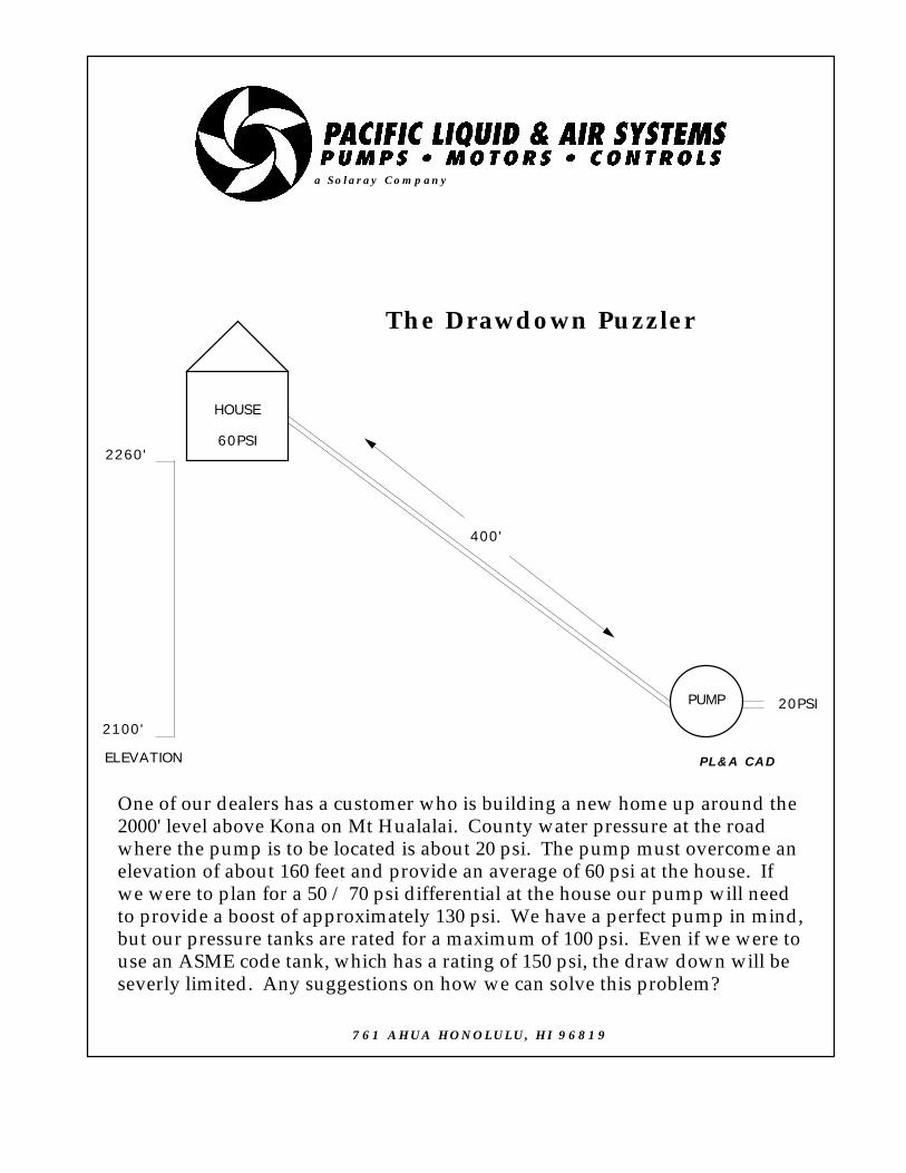
The Drawdown Puzzler
HOUSE
PUMP
2100'
2260'
ELEVATION
60PSI
20PSI
400'
One of our dealers has a customer who is building a new home up around the2000' level above Kona on Mt Hualalai. County water pressure at the roadwhere the pump is to be located is about 20 psi. The pump must overcome anelevation of about 160 feet and provide an average of 60 psi at the house. Ifwe were to plan for a 50 / 70 psi differential at the house our pump will needto provide a boost of approximately 130 psi. We have a perfect pump in mind,but our pressure tanks are rated for a maximum of 100 psi. Even if we were touse an ASME code tank, which has a rating of 150 psi, the draw down will beseverly limited. Any suggestions on how we can solve this problem?
a Solaray Company
PL&A CAD
761 AHUA HONOLULU, HI 96819
THE DRAWDOWN PUZZLER
HYDROPNEUMATIC TANKS
Joe Evans, Ph.D
It is interesting that, regardless of our intellectual ability, we are often incapable of thinking outside of the box. Because of this we sometimes miss the bigger picture. Our hydropneumatic Puzzler is an example of how this kind of thinking (or lack thereof) can cause us to miss the obvious.
In Hawaii, most of our residential water systems applications are either rainwater catchment or domestic pressure boosters. In both cases the pump and hydropneumatic tank are usually located in the same immediate area. Because of this we tend to think that a pump and tank “must” be near one another. Were we on the mainland where 4” submersibles proliferate, we would have surely noticed that there very few 50 gallon tanks located at the bottom of a 200’ well!
When pumping pressurized domestic water up hill or over long distances we should view the application as if it were that of a deep well. The pump is located at the source of the water and the hydropneumatic tank is located near its point of use. That is not to say that the tank cannot be located with the pump and, in certain instances, it can be. Generally speaking, however, the system will be more efficient and reliable if they are separated.
As in the case of the tank, one will find few pressure switches at the bottom of a deep well. It is always best to locate the switch as near the point of use as possible. In the case of a Jet Pump, its pressure switch should be removed and relocated at the tank site. Tank “Tees” are available to accommodate mounting of a switch and gauge at the tank fitting. This location will provide for a more stable on/off pressure and will eliminate the need to account for the elevation and friction
head between the pump and tank. Prior to operation, the tank should be pressurized to two pounds below the cut in pressure of the pressure switch.
Spring loaded, non-slam check valves must be located at the pump discharge and just upstream of the pressure switch and tank. Depending upon the elevation rise and/or lateral run, additional checks may be needed in between. Follow the check valve distance recommendations for submersible installations. Air release valves should also be installed at all high points in the lateral.
As with a submersible installation, wire size must be selected to accommodate the full service factor load of the pump. In the case of very long runs, where wire cost becomes a factor, power can be supplied at the pump location. The pressure switch will then function as a pilot device and supply a 115V control voltage to a magnetic starter at the pump.
In Hawaii, many applications require water to be pumped over substantial distances. and often the pump must be controlled by a sensor at the other end of the line. For these conditions, low power (3 -10ma) solid state relays will allow a 115V signal to travel several thousand feet, over small gauge wire, without a substantial loss. These are also useful when working with 24V control systems that must traverse distances that are greater than normal.
761 Ahua Honolulu, HI 96819
Phone 808.536.7699 Fax 808.536.8761www.pacificliquid.com

a Solaray Company
PL&A CAD
The Priming Puzzler
761 AHUA HONOLULU, HI 96819
20'
2'
In the sketch above, a self priming pump is lifting water about two feet and then pumpingit into a holding tank about twenty feet above. Occasionally, the foot valve will not seatproperly and pump will lose its prime. We have suggested that the customer eitherremove the check valve in the discharge line or install an air release valve on the top of thepump case. Then, even if the foot valve does fail, the pump can reprime itself withoutsomeone having to refill the suction line. Our customer, who considers herself a pumpexpert, says the 4" check valve is too difficult to remove and that an air release valveshould not be required. "After all", says she, "a centrifugal pump will develop its ratedhead while pumping any fluid, including air." Is her assumption correct? If the selfpriming pump is capable of generating fifty feet of head, should it not be able to overcomethe twenty foot water column in the discharge pipe?

THE PRIMING PUZZLER
CENTRIFUGAL PUMP PRIMING
Joe Evans, Ph.D
So, does our pump expert know what she is talking about? Can a centrifugal pump develop its rated head regardless of the fluid it is pumping? If it can generate fifty feet of head, when pumping air, can it overcome a twenty foot column of water and still prime? The answers are yes and no.
A centrifugal pump will pump air (or almost any fluid) at its rated capacity and head. When that fluid is a gas; however, its head as measured in PSI will be substantially different. Since the weight of air is only about 1/800 that of water, a fifty foot head of air will display a gauge pressure just 0.027 PSI. A column of water of the same height will indicate 21.65 PSI. Even if the pump were lifting water only one foot and discharging the air from the suction pipe to atmosphere, a discharge head of about 800 feet would be required for it to prime. In order to prime and exhaust air through a check valve supporting a 20 foot column of water, the pump shown in our puzzler would have to produce an air head of more than 16,000 feet! Now, I have known some pretty big air heads in my time but never one quite that large. It is no wonder then, that a number of other methods have been developed to facilitate the priming process.
Although I will tend to refer to water, as the pumping and priming fluid in the following examples, remember that many different fluids may be substituted.
Foot Valves
The foot valve is probably the simplest and most common method of maintaining a
centrifugal pump’s prime. Once the pump and suction piping are filled a foot valve, located at the very end (foot) of the suction pipe, maintains prime by prohibiting water from draining back to its source. Foot valves are also used on self priming pumps to eliminate priming time (or the air associated with priming) each time the pump starts.
A problem often associated with foot valves is their tendency to leak and allow air to reenter the pump and suction piping. This is especially true when particulate matter is present. Often “proof of prime” systems are employed when fail safe operation with a foot valve is required. Another factor that must be considered is NPSH. Foot valves can introduce substantial friction to the suction system. Oversizing by one or two pipe sizes is quite common.
Vacuum Priming
The figure below shows a simple vacuum priming system.
The hand operated diaphragm pump (B) removes air from the pump case and suction piping while atmospheric pressure forces water into the evacuated space. A check

valve isolates the discharge line from the pump and suction piping during priming. A foot valve can be installed to maintain prime after the initial evacuation.
Large engine driven pumps often utilize intake manifold vacuum as a priming source. Such systems may be used with or without a foot valve. Obviously care must be taken to ensure that water does not enter the engine’s intake.
Over the years, industry has relied heavily on vacuum systems to prime large centrifugal pumps. In the past steam, air, and water powered ejectors were employed as priming devices. Today electrically driven dry and wet vacuum pumps are the primers of choice. Many manufacturing and processing plants employ vacuum pumps in their central priming systems. These systems can prime a number centrifugal pumps automatically, and on an as required basis.
As in the case of foot valves, vacuum priming systems require certain considerations. A check or shut off valve must be installed on the discharge so that the pump and suction piping can be isolated during priming. Also, potential air leaks must be identified and remedied. Of particular importance is the pump’s stuffing box. Even small air leaks will prohibit a low capacity vacuum system from achieving prime. For trouble free vacuum priming either mechanical seals or a flushed packing should be installed.
Priming Tanks
Another priming method that has been around since the centrifugal pump appeared on the scene is the priming tank. A typical configuration is shown in Fig 2.
When the pump starts, water is removed from the tank and a partial vacuum is created within. Atmospheric pressure on the surface of the supply forces water up the suction pipe and into the tank. As long as the pump is operating, water is replaced at the same rate it is removed. Since the level of the water in
Figure 2
the tank during operation is lower than its initial static level, the tank must be refilled when the pump is stopped. If is not refilled, there may be an inadequate supply to insure priming the next time the pump starts. Refilling can be accomplished automatically if backflow from the discharge piping is sufficient and a discharge check valve is not used. Otherwise the tank must be refilled manually. If manual refilling is not desirable, double chamber tanks (upper & lower) are available and allow automatic refill of the lower (suction) chamber regardless of discharge conditions.
Self Primers
Relatively small centrifugal pumps (under 1000 GPM) can be designed to entrain air within the pumped liquid, separate it from the liquid, and exhaust it through a venting valve or the pump’s discharge. Early self primers used an internal valve that directed the liquid back to the eye of the
impeller after air separation. After all air was removed from the suction line, a balancing of the internal pressures caused the valve to close and liquid was directed to the discharge.
Modern self primers no longer recirculate the priming liquid back to the suction. Instead, the priming water is recirculated back to the

impeller periphery where it enters the impeller vanes and mixes with air from the suction piping. Although priming time is increased slightly with this design, the requirement for a mechanical flow director is eliminated.
Figure 3 illustrates the movement of water in a typical self priming pump both during and after the priming cycle.
Figure 3
The left side of the figure above shows air being removed from the suction piping. The initial priming water is isolated from the impeller suction by internal casting barriers. Water exits the impeller in the upper portion of the case where the entrained air is separated and exhausted through the pump discharge. The priming water circulates back to the impeller rim via a port in the lower portion of the pump case and the entrainment cycle is repeated.
The right side of the figure shows the same pump after it is primed and all suction air is removed. Here pumped water flows out of the impeller and towards the discharge via both its normal route (upper case) and the recirculation port in the lower area of the case.
Although a number of other methods are used to prime centrifugal pumps, the ones described above have proven the most popular.
761 Ahua Honolulu, HI 96819Phone 808.536.7699 Fax 808.536.8761
www.pacificliquid.com

a Solaray Company
PL&A CAD
The Suction Air Puzzler
POND
SELF PRIMING PUMP
AIR ACCUMULATION
A pineapple plantation here on Oahu has an ongoing problem withone of their irrigation pumps. As you can see from the sketch above,their installation is less than ideal. The pump lifts water from aholding pond about ten feet below the pump. Because the areabetween the pump and the pond is solid rock, the suction piping mustfollow the topography. Unfortunately this creates an elevated sectionthat is prone to air accumulation. The irrigation foreman has installeda tee at the high point of the elevated section and a foot valve at thepond. This allows him to purge the air on a weekly basis by addingwater manually. He wants to automate this purging process and hasdecided to install an air release valve on the tee. A company engineertold him that air release valves are designed for lines under positivepressure and will not work on a suction line. The foreman says thathe has seen a number of such installations at a local refinery. Is hecorrect? Can an air release valve operate on a suction line?
761 AHUA HONOLULU, HI 96819

THE SUCTION AIR PUZZLER
PIPELINE & SYSTEM AIR
Joe Evans, Ph.D
We appear to have a bit of a dilemma here. Can an air release valve be used on the suction side of a pump that is lifting water? The supervisor seems to think so but his engineer tells him it cannot. Well, strictly speaking, the word release implies that there be some action on the part of the air. But if the suction line is under a negative pressure, as it should be in a suction lift situation, accumulated air can not exit even if it were given the opportunity. Without positive pressure and compression, no energy is available to exhaust it. It would appear then, that he cannot use such a valve in this instance. But if he simply renames it an Air Separation Chamber and installs it with one additional connection, it will do the job just fine.
“Birds gotta fly and fish gotta swim”. Obviously if were not for air birds could not fly and, technically, if fish are to swim for very long they will need some too. Depending upon one’s perspective, the fact that water contains a certain amount of air may be a good or not so good thing. Fish, were they philosophical creatures, would almost certainly find it a plus while those involved water distribution may view it as just another inconvenience.
The aeration process occurs both naturally and inadvertently. In nature air enters water in many ways. The agitation of a flowing stream or river, decomposing organic matter, and the normal biological activity of marine animals and plants all contribute to the aeration process. In the pumping arena it is the stuff of leaky suction lines, surface vortexing, self priming pumps, and
inadequate shaft sealing. Air may be entrained in the form of tiny bubbles or completely dissolved within the water. How long it will remain there depends upon a number of factors but two of the more important are temperature and pressure. As temperature rises and/or pressure decreases, air has less of a tendency to remain in water. Since it is less dense than water it rises and, if it cannot escape, it will accumulate at any high point in the system.
If no provision is made to remove air from these high points, a small pocket will grow in size until it finally affects the flow of the water being pumped. Air reduces the flow of water in a system simply by reducing the area (diameter) available to flow. Figure 1 illustrates such a reduction. Here, an air pocket is shown occupying almost half the diameter of the pipe. If it continues to accumulate, flow could come to a virtual halt.
Figure 1
How much these air pockets affect flow depends upon the flow velocity and the geometry of the system. Higher velocities will often break up large air pockets into smaller ones while lower velocities have little or no effect. Also, acute angles tend to entrap more air than and do obtuse ones. In extreme cases, flow can be reduced to a fraction of normal. But regardless of the size of the pocket, air accumulation will result in some reduction in flow or an increase in power consumption if normal flow is maintained at the expense of flow area.
The Air Release Valve, shown in Figure 2, is designed to limit the formation and size of these area robbing air pockets.

Figure 2
Its purpose is to vent, continuously, small amounts of air as it separates from a pumped liquid. Air Release Valves are installed vertically at all high points of a pressurized system. During normal flow conditions, the float ball is buoyed upward by water within the valve body. In this position the valve’s plug or orifice button is held tightly against the valve seat by the float linkage. As air accumulates in the upper portion of the housing, it forces the water level down, the float descends, and the valve opens. As the entrapped air vents to atmosphere, the float again rises and closes the valve discharge orifice before water can exit.
Air Release Valves can be installed almost anywhere air can accumulate in a pressurized system. They are found on pipelines, pressure vessels, and self priming pumps. They are also available for wastewater pipelines. The solids present in municipal sewage would cause problems for the valve shown in Figure 2. Special sewage valves incorporate longer bodies and float rods so that the float and the water level are well removed from the discharge orifice. This reduces the chance that solids will interfere with the valve closing mechanism and valve seat.
There are times; however, when we may want air to enter a system and still other times when we need to exhaust large amounts of air very quickly. For example,
when a tank or pipeline is drained air must replace the liquid that is removed or a vacuum will be created. Such a condition, if allowed to continue, could cause the container to collapse due to atmospheric pressure on its exterior. Similarly, when a pipeline or container are refilled the air must be exhausted to make room for the liquid. The Air / Vacuum valve was designed for this very purpose and is shown in Figure 3.
Figure 3
The Air / Vacuum Valve is designed to pass large volumes of air in either direction. The major difference between it and the Air Release Valve is the size of the discharge (also inlet) orifice. Also, the float serves the dual function of float and valve plug. It is not, however, designed to operate as an Air Release Valve. The outlet orifice is sized to accommodate anywhere from 30 to 700 cubic feet per second as opposed to the release valve’s 3 - 150 cubic feet per minute.
If an application requires both air release and air / vacuum protection, a Combination Air Valve can be installed. As its name implies, this valve combines both functions into a single unit. Usually the valve is designed with a double housing that incorporates the individual mechanical components of both valve types.
OK, enough about discharge air. Lets get back to our Puzzler and the problem of air accumulation in the suction piping. It is pretty obvious that a standard air release

valve will fail to release air if there is no pressure to force the air out. In fact, it will introduce even more air into the system because, when open, it is nothing more than a big air leak!
Figure 4 shows the answer to the irrigation foreman’s prayers. It is an adaptation of the air release valve known as an Air Separation Chamber. The one shown is a flow through device designed for installation at a pump’s suction, although it can be installed anywhere in the pipeline. More compact units, similar in size to sewage Air Release Valves, are available for mounting on a tee.
TO PUMPSUCTION
FROMSUPPLY
TO VACUUMSYSTEM
Figure 4
Like the air release valve it has a float mechanism that opens as air accumulates in the upper portion of the chamber. The chamber is somewhat larger though, and allows accumulation of a larger volume of air before the valve opens.
The major difference is that its discharge is connected to a vacuum source rather than venting to atmosphere. Since a partial vacuum exists in the suction line during suction lift conditions, some exterior vacuum source must be applied to overcome it. The only requirement is that the source must produce a higher vacuum than that of the suction line.
In the process or manufacturing environment, the chamber is usually connected to the plant’s central vacuum system. In the field it will often have its own dedicated vacuum pump/tank. In some applications, an ejector on the discharge side
of the pump is all that is required to support an air removal chamber. And, for relatively small accumulations in remote locations, a vacuum tank and check valve may be adequate. The tank must be reevacuated from time to time with a portable vacuum pump.
The best way to eliminate air accumulation in a pumping system, be it suction or discharge, is to prevent its entry. In the real world, however, there will be many times when we must design or build a system that is less than perfect. It is during these times that we can make good use of air release and removal valves.
761 Ahua Honolulu, HI 96819Phone 808.536.7699 Fax 808.536.8761
www.pacificliquid.com

a Solaray Company
761 Ahua StreetHonolulu, Hawaii 96819Phone 808.536.7699Fax [email protected]
The 4" Motor Puzzler
Towards the end of the 20th century, pump installers began to report unusual failures in some of their 4” submersible well pump installations. By unusual, I mean destruction! They found twisted or broken pump shafts, stripped splines, and even broken motor shafts. The common thread was that most involved pumps installed on 5 HP, single phase, 4” Franklin motors. Few, if any, three phase installations experienced any of these problems and smaller single phase installations seemed equally immune as well.
What is the source of these problems? Are pump manufacturers or that venerable motor manufacturer lowering the quality of their materials? Is mass production the culprit or could it be sloppy assembly in the field? Fortunately our faith in these products can remain in tact as none of the aforementioned reasons were the cause. It is just another example of physics biting us on the butt when we don’t pay attention to its laws
THE 4” MOTOR PUZZLER
Nikola Tesla Meets Isaac Newton
Joe Evans, Ph.D
This Puzzler is not intended to cast dispersions on Franklin Electric or any of the pump companies that use its product. Its just a good example of what can happen when progress ignores basic physics.
In our competitive, free market society, pump manufacturers strive to take advantage of every ounce of horsepower a motor can provide. After all who would want to market a pump that delivers only 90% of that of his competitor? But when we push a product to its limits unexpected results can occur.
Shaft damage is not all that uncommon in constant torque applications (ie positive displacement pumps). Variable torque applications (ie centrifugal pumps), on the other hand, usually do not share this problem. What happened in this instance is that two branches of physics (electricity and mechanics) worked together to produce these undesired results. That these failures were limited to a single model is, at first, a bit puzzling but a brief look at the simple physics involved will make it quite clear.
The Tesla Side of the Coin
The modern electric motor, invented by Nikola Tesla, operates via the principle of induction.1 A current in the motor’s stator creates a magnetic field which in turn “induces” a current in the rotor. The magnetic field produced by the induced current opposes (like NN or SS magnets) the field in the stator and the force produced causes the rotor to rotate. The speed (RPM) 1 For a basic introduction to electric motors and induction see “The Three Phase Induction Motor” located on the Education page of our web site.www.pacificliquid.com/motorintro.pdf
at which the rotor rotates depends upon the frequency of the current and the number of fields (poles) produced in the stator.
If one were to wind a single phase stator in a manner that creates two winding groups 180º apart, the result is referred to as a two pole motor. Since AC current in the USA alternates sixty times each second (60hz), the two poles are energized a total of sixty times during one second’s time. If the rotor could respond effortlessly to these opposing fields, it would rotate at 3600 RPM (60 X 60). But in the real world, outside forces reduce this theoretical (synchronous) speed to a lower value. Actual speed, often called slip speed, hovers between 3450 and 3550 RPM.
Now, if we were to increase the number of poles to four (90º apart), it would take twice as many cycles for the current to circle the stator’s windings. The result is a motor that rotates at 1800 RPM. Increase the number of poles to six (60º apart) and rotational speed drops to 1200 RPM. Theoretically this could go on forever but, at some point, one runs out of room or the stator becomes impracticably large.
When AC current in the stator induces a current in the rotor, the rotor undergoes acceleration and continues to accelerate as long as the magnetic fields oppose one another. When the fields subside, the rotor ceases to accelerate and, immediately, begins to slow. How much it slows depends upon the distance (in degrees) to the next magnetic interaction. With a six pole motor the distance is only 60º but in a two pole motor the rotor must travel three times that distance before it is reaccelerated. Because this distance is so great two pole, single phase motors incorporate a set of “start” windings that serve to reduce this distance during starting. Three phase motors do not encounter this distance problem because each phase has its own set of poles. A three phase, two pole motor actually has six distinct poles 60º apart. By timing the phases properly, it can still operate at 3600 RPM but does so with the help of three times as many induced accelerations per unit of time.

The Newtonian Side of the Coin
You have probably already deduced (a little reverse induction humor) that the time between reaccelerations in the two pole, single phase motor is the cause of the failures described in the puzzler. But why does it occur in just the 5 HP model? After all the 1/2 - 3 HP models operate in exactly the same manner. And, why not the 5 HP, 6” model? Should it not experience similar problems?
1) In part, Newton’s First Law (inertia) states that an object in motion will remain in motion at a constant velocity unless it is acted upon by some outside force. In the case of a submersible electric motor, these outside forces are friction (radial and thrust bearings) and the load produced by the pump.
2) In part, his Second Law says that the acceleration that an object undergoes when acted upon by a force will be directly proportional the size of the force and inversely proportional to the mass of the object. Therefore a more massive motor rotor will accelerate more slowly than a smaller one when acted upon by the same force. But, the reverse is also true! The more massive rotor will also decelerate more slowly than a smaller one.
It is this combination of deceleration, acceleration, and the time lapse between the two that is the real culprit. The torque required to reaccelerate the 5 HP rotor, under these conditions, can be considerably more than normal.2
As I mentioned earlier, shaft and coupling problems are common with reciprocating machines. Although they are called “constant torque” machines, the torque required at different points of a single operating cycle is anything but constant. Take the single acting piston pump for example. Much more torque is required during the discharge portion of the pumping
2 For a review of torque see the “My Shafts Bigger Than Yours” Puzzler on the Education page of our web Site. www.pacificliquid.com/puzcomplete.pdf
cycle than is required during the suction portion. Therefore during each pumping cycle torque will peak and then subside. Even the double acting pump undergoes torque peaks during its pumping cycle. The common method of evening out these torque demands on a motor is the incorporation of a flywheel.3 The flywheel adds additional inertia to the process and helps to unload the motor during times of peak torque.
The more massive rotor of the 6” Franklin motor acts like a flywheel and adds additional inertia to the process. The lower horsepower 4” motors also tend to be immune because their rotors are also quite massive relative to their power output. It is only the 5 HP model, whose rotor is not that much larger than the 3 HP unit but produces over 60% more HP, that is subject to the failures described in the puzzler. Because of its relatively low inertia and higher loading, it decelerates more quickly between induction cycles. The torque required to get it back to speed becomes higher than normal and creates a “torque pulse” that can potentially damage the rotating components.
So what can be done to alleviate this problem? Probably the easiest fix is not to load the motor to the max but, that will be difficult as long as competition exists. Another, more probable, outcome is to beef up the motor and pump shaft components. Regardless of what is done, the problem will never go away, but it probably can be made tolerable.
761 Ahua Honolulu, HI 96819Phone 808.536.7699 Fax 808.536.8761
www.pacificliquid.com
3 For a review of flywheels and rotational inertia see the
“WK2” Puzzler located on the Education page of our web site. www.pacificliquid.com/puzcomplete.pdf


![PHYS-1600/2000PHYS-1600/2000 II5 Internal ForcesNEBRASKA WESLEYAN UNIVERSITYFALL 2014-2015 DEAN SIEGLAFF NATHANIEL CUNNINGHAM of 11 1 [Insert Puzzler Here]](https://static.fdocuments.in/doc/165x107/56649e2e5503460f94b1e70c/phys-16002000phys-16002000-ii5-internal-forcesnebraska-wesleyan-universityfall.jpg)