The Pre–Charge - Iowa State...
12
The Pre–Charge System Troubleshooting Guide Joshua Straquadine
Transcript of The Pre–Charge - Iowa State...

The
Pre–Charge System
Troubleshooting Guide
Joshua Straquadine

Table of Contents
1
Introduction
Quick Guide, Warning
Equipment Needed
System Overview
High Voltage Map
Isolating the Problem
Step 1: General Inspection
Step 2: The Relay
Step 3: The Logic Gate
Step 4: The Comparator
Still Having Problems?
Glossary of Terms
2
3
4
5
6
7
9
11
13
15
17
18
18
Pin—Name for any conductive metal protrusion designed for
connecting electrical components together.
Printed Circuit Board (PCB)—A flat panel with copper
“wires” etched into its surface. PCBs allow for easy intercon-nection and sturdy mounting for electrical systems.
Trace—Name for the conductive “wires” which are printed
onto a printed circuit board, which create electrical connec-tions between components.
MOSFET—Metal-Oxide-Semiconductor Field Effect Transistor.
A three-pin semiconductor device which acts like an electrically controlled switch. Changing the voltage one of the pins can connect or disconnect the other two pins from each other.
Relay—Electromagnetic device which acts like an electrically
controlled switch. Passing electrical current through the elec-tromagnetic coil creates a magnetic field which closes a switch.
Heat Sink—device for dissipating heat from electrical compo-
nents. Passing current through any electrical component will cause it to heat up, and the heat sink prevents the heat from damaging it.
Logic gate—electrical component which performs operations
or makes decisions based on its input signals.
Comparator—component which takes in two analog signals,
and puts out a digital signal depending on which input is at a higher voltage.
Glossary of Terms
The Pre-Charge System
Troubleshooting Guide
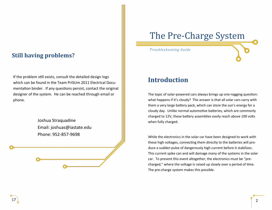
The topic of solar-powered cars always brings up one nagging question:
what happens if it’s cloudy? The answer is that all solar cars carry with
them a very large battery pack, which can store the sun’s energy for a
cloudy day. Unlike normal automotive batteries, which are commonly
charged to 12V, these battery assemblies easily reach above 100 volts
when fully charged.
While the electronics in the solar car have been designed to work with
these high voltages, connecting them directly to the batteries will pro-
duce a sudden pulse of dangerously high current before it stabilizes.
This current spike can and will damage many of the systems in the solar
car. To prevent this event altogether, the electronics must be “pre-
charged,” where the voltage is raised up slowly over a period of time.
The pre-charge system makes this possible.
Introduction
2
If the problem still exists, consult the detailed design logs
which can be found in the Team PrISUm 2011 Electrical Docu-
mentation binder. If any questions persist, contact the original
designer of the system. He can be reached through email or
phone.
17
Joshua Straquadine
Email: [email protected]
Phone: 952-857-9698
Still having problems?
16
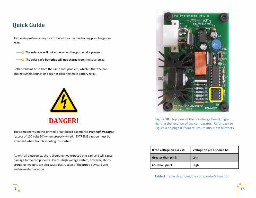
Figure 10: Top view of the pre-charge board, high-lighting the location of the comparator. Refer back to Figure 4 on page 8 if you’re unsure about pin numbers.
Table 1: Table describing the comparator’s function
If the voltage on pin 2 is: Voltage on pin 6 should be:
Greater than pin 3 Low
Less than pin 3 High
3
Two main problems may be attributed to a malfunctioning pre-charge sys-
tem:
The solar car will not move when the gas pedal is pressed.
The solar car’s batteries will not charge from the solar array.
Both problems arise from the same root problem, which is that the pre-
charge system cannot or does not close the main battery relay.
Quick Guide
DANGER!
The components on this printed circuit board experience very high voltages
(excess of 100 volts DC) when properly wired. EXTREME caution must be
exercised when troubleshooting this system.
As with all electronics, short-circuiting two exposed pins can and will cause
damage to the components. On this high voltage system, however, short-
circuiting two pins can also cause destruction of the probe device, burns,
and even electrocution.

Tip:
Whenever possible, use a testing
probe with a spring loaded clip like
in Figure 9. They allow you to set it
once and then free up your hands,
letting you accomplish more.
As mentioned earlier, the pre-charge system slowly increases
the voltage for the electronics in the car. In order to decide
when to stop the pre-charge process, the system requires some
sort of sensor. A comparator module simply compares two ana-
log voltages and outputs a digital signal (high or low) depending
on which of those signals is larger. In the context of the pre-
charge system, the comparator makes the decision on whether
or not the high-voltage electronics are at a high enough voltage
to close the relay.
The comparator device on this board is an 8-pin DIP package, as
seen in Figure 10. Pins 2 and 3 are the inputs, and pin 6 is the
output. Carefully probe the voltages on these three pins. Com-
pare these voltages to the cases in Table 2. If reality doesn’t
match one of these cases, replace the chip.
Step 4: The Comparator
15
Figure 9: Spring loaded testing probes can be clipped directly to the pins under test.
Equipment Needed
4
One Malfunctioning Solar Car
One Handheld Voltmeter
Two Voltmeter Probes
One Soldering Iron One Spool of Solder

Overview: What’s what on this board?
5
Figure 1: Elevated view of the board, labeling important components
Figure 2: The connector, shown looking edge-on with the board, labeling the functions of each pin. 14
If pin 5 is: And pin 6 is: Then pin 4 should be:
Low Low High
Low High Low
High Low Low
High High Low
Figure 8: Top view of the pre-charge board, high-lighting the location of the logic chip. Refer back to Figure 4 on page 8 if you’re unsure about pin numbers
Table 1: Logic function of the chip
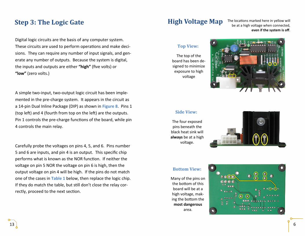
Top View:
High Voltage Map The locations marked here in yellow will be at a high voltage when connected,
even if the system is off.
The top of the board has been de-signed to minimize exposure to high
voltage
Side View:
The four exposed pins beneath the
black heat sink will always be at a high
voltage.
Bottom View:
Many of the pins on the bottom of this board will be at a high voltage, mak-ing the bottom the
most dangerous area.
6
Digital logic circuits are the basis of any computer system.
These circuits are used to perform operations and make deci-
sions. They can require any number of input signals, and gen-
erate any number of outputs. Because the system is digital,
the inputs and outputs are either “high” (five volts) or
“low” (zero volts.)
A simple two-input, two-output logic circuit has been imple-
mented in the pre-charge system. It appears in the circuit as
a 14-pin Dual Inline Package (DIP) as shown in Figure 8. Pins 1
(top left) and 4 (fourth from top on the left) are the outputs.
Pin 1 controls the pre-charge functions of the board, while pin
4 controls the main relay.
Carefully probe the voltages on pins 4, 5, and 6. Pins number
5 and 6 are inputs, and pin 4 is an output. This specific chip
performs what is known as the NOR function. If neither the
voltage on pin 5 NOR the voltage on pin 6 is high, then the
output voltage on pin 4 will be high. If the pins do not match
one of the cases in Table 1 below, then replace the logic chip.
If they do match the table, but still don’t close the relay cor-
rectly, proceed to the next section.
Step 3: The Logic Gate
13

Isolating the Problem
Before spending much time probing the pre-charge system, test
around to make sure that pre-charge is actually the culprit.
Check to see if the connector has been plugged into the
pre-charge board. The single, eight-wire connector
must make good contact to properly transmit signals to
and from the board.
Using a voltmeter, test the voltage from the power supply
(the two light blue pins in Figure 3). These two wires
attach directly to the power regulation system, and
should be at a voltage at 12 volts (V). If the voltage be-
tween these wires is substantially different from 12 V,
troubleshoot the Power Regulation System.
Check the input “enable” signal from the battery protec-
tion system (BPS). This signal will appear on the pin la-
beled in green in Figure 3. The voltage on this pin
should be 5 V when the system is disabled, and 0 V
when enabled. If the voltage on this line doesn’t match
up to the proper case, then troubleshoot the Battery
Protection System.
7 12
Figure 7: The connector, seen looking edge-on with the board. Marked in yellow are the two pins connected to the main relay’s electromag-net. The voltage between these two pins direct-ly controls when the relay switch should close.
Figure 6: Image of the main re-lay. The two thin protruding wires connect internally to the electromagnet, while the bolts on top connect to the switch.
Figure 5: Schematic symbol of a relay. The magnetic field creat-ed by the electromagnet pulls the switch closed.
Note: Never use the continuity setting on a multimeter to check if a relay is
closed. Instead, measure the voltage between the terminals. Zero
volts means the relay is closed.

Step 2: The Relay
11
A relay is basically a switch controlled by an electromagnet
(Figure 5). When the magnet is energized, the switch will
close, completing the electrical circuit. A very large, robust re-
lay is used to connect or disconnect the battery pack in the so-
lar car, and it is directly controlled by the pre-charge system.
Whenever the relay opens or closes, it is accompanied by a
loud click.
In the solar car, this component IS NOT found on the pre-
charge board, simply because of its size. It is located nearby,
hooked up to the pre-charge board through the connector.
The relay used in the solar car can be seen in Figure 6.
Begin by probing the voltage between the C+ and C- pins on
the connector (Figure 7). The voltmeter will read 12 volts if
pre-charge is trying to close the relay and zero volts if it is not.
If the difference between these two pins is 12 V but the relay
hasn’t closed, the relay must have failed. Replace the relay
with a new one.
If the relay responds correctly, then the voltage on the pins
must be incorrect. For instance, if the battery protection sys-
tem is sending the enable signal but the relay pins are at zero
volts, some portion of the control system on the board has
failed. If this is the case, proceed to the next section. If the problem still exists after checking the above points, the
problem must be somewhere within the pre-charge system.
Figure 3: The pre-charge connector, as seen looking edge-on with the board, showing power connections (cyan) and enable signal connection (green)
Tip:
Disconnect the pre-charge system entirely
for this step. You can insert your voltmeter
probes directly into the plug to measure
what the other systems are sending to the
pre-charge board.
8

Tip:
If you find yourself repeatedly
testing the same hard-to-reach
pin, solder an extension wire to it.
You can easily remove it when
you’re done.
If the board still doesn’t work after running though these
questions, proceed to the next section.
Figure 4: Dual Inline Package (DIP) components and sockets. The sockets make it easy to replace a damaged component, but also make it easy to insert components backwards.
10 9
Step 1: General Inspection
With many electronic systems, problems can be found quickly
and easily just by looking at it. Give the board a quick once-over
and ask yourself these simple questions:
Is the power on? Has the connector been plugged in? Are all of the components installed? Are they all installed correctly? Especially with com-
ponents in a Dual Inline Package (DIP), it’s easy to install a component backwards. Also, this board contains two 8-pin DIP packages with different part numbers. Refer to Figure 4 to check the orien-tation of the components.
Do any of the components show signs of physical
damage? Some devices can burn, melt, smoke, or even explode.
Are the solder joints complete? Smooth and shiny
joints are best; jagged surfaces indicate weak con-nections.
Joshua Straquadine English 314
Pre-Charge System Troubleshooting Guide Usability Test Plan The purpose of this troubleshooting guide is to assist a member of the solar car team with finding the problem with, and repairing, a malfunctioning pre-charge system. This document assumes that the reader can read and understand English at an eighth grade level or above, already understands the most basic electrical concepts, and is proficient in the use of a voltmeter. Beyond that, however, nothing else is assumed. The board is presented as if the reader has never seen it before. In order to verify the document’s usability, the following test procedure will be followed:
The pre-charge board will be “broken,” simulating a fault which is addressed in the document.
For safety, the device will be removed from the high-voltage components of the solar car and instead hooked up to an alternate test rig which can simulate the same conditions, simply at a safer voltage.
The reader will be provided all of the necessary equipment: o The “malfunctioning” circuit board and testing rig o Voltmeter and probes o Soldering iron and solder o The troubleshooting guide
The reader will be asked to identify and remedy the simulated problem.
The entire test will be repeated, this time simulating a different fault. During this procedure, the author will observe the reader’s reactions. Ultimately, the reader’s ability to find and fix the problem will determine the success or failure of the document.
Date: March 21, 2011 To: Prof. M. Satterwhite, Engl 314 From: Joshua Straquadine Subject: Results of usability test for Pre-Charge Troubleshooting Guide The usability test outlined in the usability test plan was carried out on Saturday, March 19th. All of the specified conditions were met, with one exception. The reader did not, as specified, have any prior experience with any electrical systems, and did not have a basic understanding of electrical concepts or the use of electrical test equipment. To even the playing field for this test, I instructed her very briefly on a few topics, such as how to use a voltmeter, but nothing specific to the pre-charge system. This test was conducted twice, with two different simulated “fault” conditions. The first was that the logic chip was inserted backwards into the system, and the second was that the comparator chip was replaced with a faulty one. In both cases, the subject was able to find and fix the problems. The reader was able to find all of the necessary information and hints to complete the task, but she did not always have an easy time navigating the text. She frequently had to flip between pages (which were at that time full 8½ by 11 sheets) to reference the different tables and figures. Usually this problem was exacerbated by the fact that she held the voltmeter probes in one hand and flipped the page with the other. Clearly, that format simply wasn’t ideal for the context of use, and has since been reduced to an 8½ by 5½ booklet. I considered rearranging or repeating the important tables and figures, but decided against it. In order to speed along the process of finding the desired graphic or chart, I included a table of contents inside the front cover. Also, the reader had to ask me a few times regarding terminology. All of the concepts were those which I had thought to be very basic, and those which would have been understood by a beginner electrical or computer engineering student. To expand my audience, however, I decided to include a brief glossary of terms inside the back cover of the document. Other than the above points, minimal changes have been made to the document. The test subject did not have any problems reading and understanding the visuals or orienting herself on the circuit board. She was able to follow the logical progression from step to step, and could easily avoid the hazardous “high voltage.” As was specified in the test plan, the high voltage was actually removed from the circuit, but the test subject was able to avoid it anyway. Finally, as an added bonus, she was able to glean an understanding of several basic electrical ideas from it, even though that was not the original goal. Overall, the document was a success, and it has been improved even further since the test.